
Rockwell Automation Publication LGEM5K-GR016M-EN-E - November 2022
Supersedes Publication LGEM5K-GR016L-EN-E
Original Instructions
Studio 5000 Logix Emulate
Getting Results Guide
Studio 5000 Logix Emulate Getting Results Guide
2 Rockwell Automation Publication LGEM5K-GR016M-EN-E - November 2022
Important User Information
Read this document and the documents listed in the additional resources section about installation, configuration, and
operation of this equipment before you install, configure, operate, or maintain this product. Users are required to familiarize
themselves with installation and wiring instructions in addition to requirements of all applicable codes, laws, and standards.
Activities including installation, adjustments, putting into service, use, assembly, disassembly, and maintenance are required to
be carried out by suitably trained personnel in accordance with applicable code of practice.
If this equipment is used in a manner not specified by the manufacturer, the protection provided by the equipment may be
impaired.
In no event will Rockwell Automation, Inc. be responsible or liable for indirect or consequential damages resulting from the use
or application of this equipment.
The examples and diagrams in this manual are included solely for illustrative purposes. Because of the many variables and
requirements associated with any particular installation, Rockwell Automation, Inc. cannot assume responsibility or liability for
actual use based on the examples and diagrams.
No patent liability is assumed by Rockwell Automation, Inc. with respect to use of information, circuits, equipment, or software
described in this manual.
Reproduction of the contents of this manual, in whole or in part, without written permission of Rockwell Automation, Inc., is
prohibited.
Throughout this manual, when necessary, we use notes to make you aware of safety considerations.
WARNING: Identifies information about practices or circumstances that can cause an explosion in a hazardous environment, which may lead to
personal injury or death, property damage, or economic loss.
ATTENTION: Identifies information about practices or circumstances that can lead to personal injury or death, property damage, or economic loss.
Attentions help you identify a hazard, avoid a hazard, and recognize the consequence.
IMPORTANT
Identifies information that is critical for successful application and understanding of the product.
Labels may also be on or inside the equipment to provide specific precautions.
SHOCK HAZARD: Labels may be on or inside the equipment, for example, a drive or motor, to alert people that dangerous voltage may be present.
BURN HAZARD: Labels may be on or inside the equipment, for example, a drive or motor, to alert people that surfaces may reach dangerous
temperatures.
ARC FLASH HAZARD: Labels may be on or inside the equipment, for example, a motor control center, to alert people to potential Arc Flash. Arc Flash
will cause severe injury or death. Wear proper Personal Protective Equipment (PPE). Follow ALL Regulatory requirements for safe work practices and
for Personal Protective Equipment (PPE).
Rockwell Automation recognizes that some of the terms that are currently used in our industry and in this publication are not in
alignment with the movement toward inclusive language in technology. We are proactively collaborating with industry peers to
find alternatives to such terms and making changes to our products and content. Please excuse the use of such terms in our
content while we implement these changes.

Rockwell Automation Publication LGEM5K-GR016M-EN-E - November 2022 3
Table of Contents
Summary of changes ................................................................................... 7
Additional resources .................................................................................... 7
Legal Notices ................................................................................................ 7
Chapter 1
Install Studio 5000 Logix Emulate ............................................................ 11
Uninstall Studio 5000 Logix Emulate ...................................................... 12
Chapter 2
Overview of Studio 5000 Logix Emulate .................................................. 15
Differences between Logix5000 controllers and Studio 5000 Logix
Emulate controllers .................................................................................... 15
Special instructions for Studio 5000 Logix Emulate ............................... 16
Use Studio 5000 Logix Emulate in project development ........................ 17
Floating point calculations ........................................................................ 17
Get assistance when using Studio 5000 Logix Emulate .......................... 18
Chapter 3
Start Studio 5000 Logix Emulate .............................................................. 21
Studio 5000 Logix Emulate ....................................................................... 21
Hide slots in the virtual chassis ................................................................ 22
Hide the computer name in the virtual chassis ...................................... 22
Change the update rate ............................................................................. 22
Keep Studio 5000 Logix Emulate on top ..................................................23
Chapter 4
Configure Studio 5000 Logix Emulate ..................................................... 25
Create a Studio 5000 Logix Emulate controller ...................................... 25
Set the speed of time for a Studio 5000 Logix Emulate controller ........ 27
Create simulated I/O ................................................................................. 28
Create a 1789-SIM module in the virtual chassis .................................... 28
Create a 1756-Module in a Studio 5000 Logix Designer project ............ 29
Remove a module ...................................................................................... 30
Clear the configuration of the virtual chassis ......................................... 30
Configure trace windows........................................................................... 31
Chapter 5
Change the mode of a Studio 5000 Logix Emulate controller ............... 33
Change a Studio 5000 Logix Emulate controller to Program mode ...... 33
Change all Studio 5000 Logix Emulate controllers to Program mode .. 34
Change a Studio 5000 Logix Emulate controller to Run mode .............. 34
Preface
Installation
Overview
Start the Studio 5000 Logix
Emulate application
Configure the Studio 5000 Logix
Emulate application
Change the mode of an
emulated controller

Table of Contents
4 Rockwell Automation Publication LGEM5K-GR016M-EN-E - November 2022
Change all Studio 5000 Logix Emulate controllers to Run mode ........... 35
Change a Studio 5000 Logix Emulate controller to Remote mode ........ 35
Set the mode of a Studio 5000 Logix Emulate controller to Single Scan
...................................................................................................................... 35
Emulator Controller Status Indicators ..................................................... 36
Simulator Module Status Indicators ........................................................ 37
Chapter 6
Connect a Studio 5000 Logix Emulate controller to Studio 5000 Logix
Designer ..................................................................................................... 39
Create a communications driver for a Studio 5000 Logix Emulate
controller ..................................................................................................... 39
Configure a Studio 5000 Logix Designer project to use the Studio 5000
Logix Emulate controller .......................................................................... 40
Configure communications in a Studio 5000 Logix Designer project .. 41
Connect a Studio 5000 Logix Emulate controller from a remote
computer ..................................................................................................... 41
Chapter 7
Connect a Studio 5000 Logix Emulate controller to a FactoryTalk View
project through FactoryTalk Linx ............................................................. 43
Prerequisites .............................................................................................. 43
FactoryTalk Linx module in the virtual chassis ....................................... 44
Configure a FactoryTalk Linx server for Studio 5000 Logix Emulate ... 44
Tag Browser in FactoryTalk View ME or FactoryTalk View SE .............. 45
Chapter 8
Connect a Studio 5000 Logix Emulate controller to a FactoryTalk View
project through OPC .................................................................................. 47
Create an OPC topic for a Studio 5000 Logix Emulate controller ......... 47
Create a communications node in a FactoryTalk View project .............. 48
Configure a tag in a FactoryTalk View project ........................................ 49
Chapter 9
Program breakpoints and tracepoints ..................................................... 51
Breakpoints ................................................................................................ 51
Example BPT instruction .................................................................... 52
Program a BPT instruction................................................................. 52
Breakpoint trace window .................................................................... 53
Tracepoints ................................................................................................. 53
Example TPT instruction ..................................................................... 54
Program a TPT instruction .................................................................. 54
Connect an emulated controller
to Studio 5000 Logix Designer
Connect an emulated controller
to a FactoryTalk View project
through RSLinx Enterprise
Connect an emulated controller
to a FactoryTalk View project
through OPC
Breakpoint and tracepoint
instructions

Table of Contents
Rockwell Automation Publication LGEM5K-GR016M-EN-E - November 2022 5
Tracepoint trace window ..................................................................... 55
String formats for a tracepoint or breakpoint instruction ..................... 55
Types for formatting tag values .......................................................... 56
Chapter 10
Simulate I/O ............................................................................................... 59
Configure a produced tag ......................................................................... 59
Make the producer an I/O module of the consumer .............................. 60
Create a consumed tag ............................................................................... 61
Chapter 11
Work with trace windows ......................................................................... 63
Open a trace window ................................................................................. 63
Open trace windows for new traces automatically .................................. 63
Close all trace windows ............................................................................. 64
Remove all traces ....................................................................................... 64
Log new traces to disk ............................................................................... 64
Log traces to a new log file ......................................................................... 65
Stop logging traces to a log file ................................................................ 66
Chapter 12
Work with snapshots of Studio 5000 Logix Emulate controller states . 67
Save a snapshot of the state of multiple Studio 5000 Logix Emulate
controllers ................................................................................................... 67
Restore the state of multiple Studio 5000 Logix Emulate controllers .. 68
I/O simulation
Trace windows
Snapshots of Studio 5000 Logix
Emulate controller states
Index
Rockwell Automation Publication LGEM5K-GR016M-EN-E - November 2022 7
Preface
The Studio 5000 Automation Engineering & Design Environment® combines
engineering and design elements into a common environment. The first
element is the Studio 5000 Logix Designer® application. The Logix Designer
application is the rebranding of RSLogix 5000® software and will continue to
be the product to program Logix 5000™ controllers for discrete, process,
batch, motion, safety, and drive-based solutions.
The Studio 5000® environment is the foundation for the future of
Rockwell Automation® engineering design tools and capabilities. The Studio
5000 environment is the one place for design engineers to develop all
elements of their control system.
This manual includes new and updated information. Use these reference
tables to locate changed information.
Global changes
None for this release.
New or enhanced features
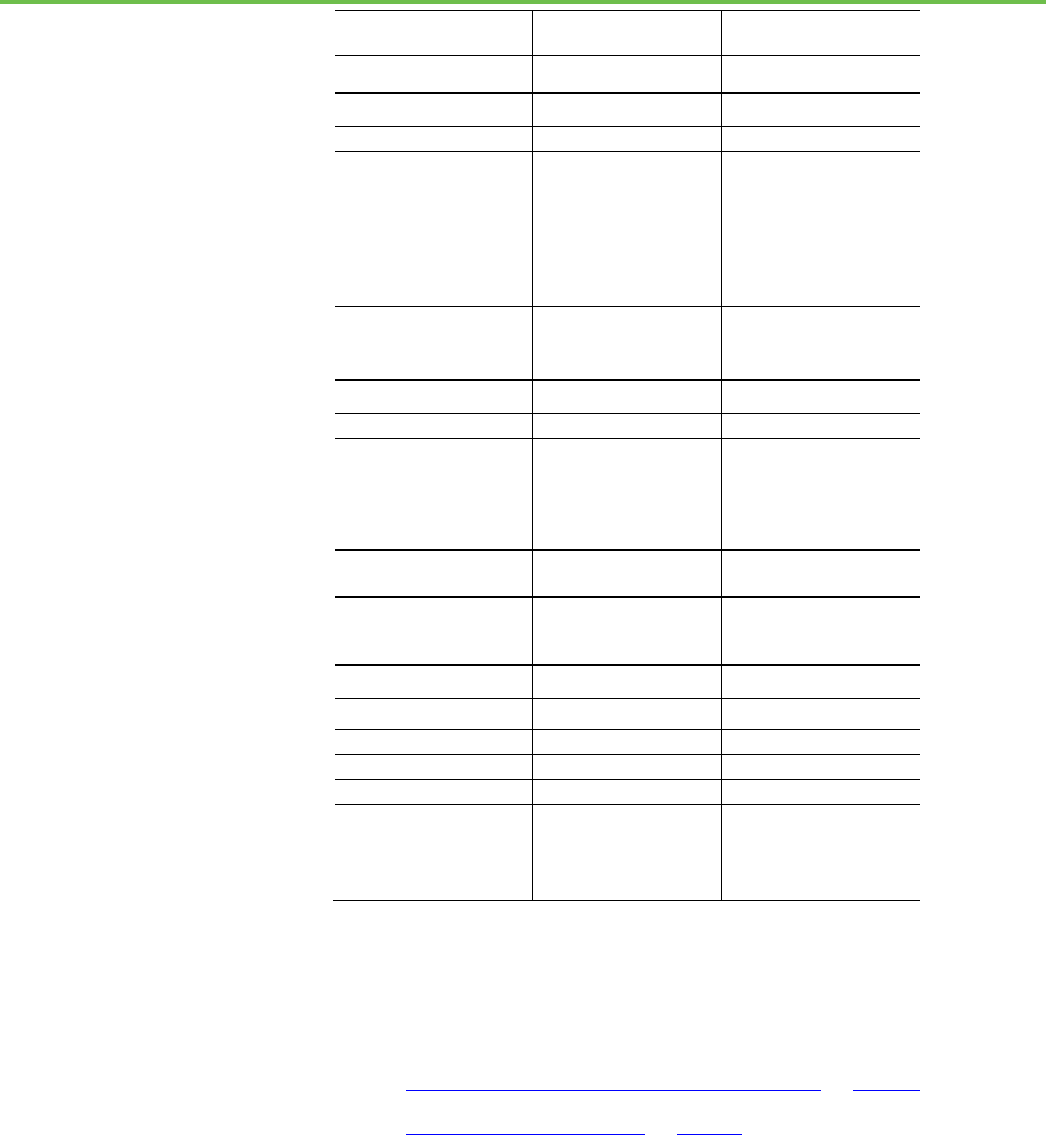
This table contains a list of topics changed in this version, the reason for the
change, and a link to the topic that contains the changed information.
Topic Name
Reason
Differences between Logix5000 controllers
and Studio 5000 Logix Emulate controllers on
page 15
Removed the JXR instruction, which is no longer supported.
Create a Studio 5000 Logix Emulate controller
on page 25
Added a description for the new Use RSLinx Classic check
box.
This document contains additional information concerning related Rockwell
Automation products.
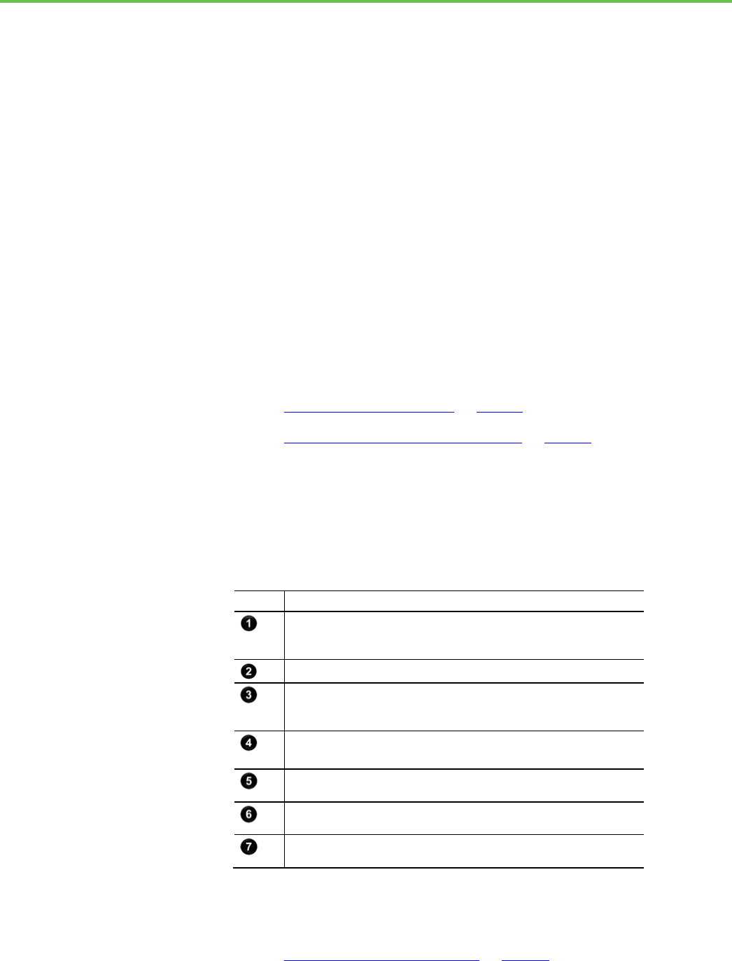
Resource
Description
Product Certifications webpage, available at
http://ab.rockwellautomation.com
Provides declarations of conformity, certificates,
and other certification details.
You can view or download publications at
http://www.rockwellautomation.com/literature. To order paper copies of
technical documentation, contact your local Rockwell Automation distributor
or sales representative.
Summary of changes
Additional resources
Legal Notices

Preface
8 Rockwell Automation Publication LGEM5K-GR016M-EN-E - November 2022
Copyright notice
Copyright © 2022 Rockwell Automation Technologies, Inc. All Rights
Reserved. Printed in USA.
This document and any accompanying Rockwell Software products are
copyrighted by Rockwell Automation Technologies, Inc. Any reproduction
and/or distribution without prior written consent from Rockwell Automation
Technologies, Inc. is strictly prohibited. Please refer to the license agreement
for details.
End User License Agreement (EULA)
You can view the Rockwell Automation End User License Agreement (EULA)
by opening the license.rtf file located in your product's install folder on your
hard drive.
The default location of this file is:
C:\Program Files (x86)\Common Files\Rockwell\license.rtf
Open Source Licenses
The software included in this product contains copyrighted software that is
licensed under one or more open source licenses. Copies of those licenses are
included with the software. Corresponding Source code for open source
packages included in this product are located at their respective web site(s).
Alternately, obtain complete Corresponding Source code by contacting
Rockwell Automation via the Contact form on the Rockwell Automation
website:
http://www.rockwellautomation.com/global/about-us/contact/contact.page
Please include "Open Source" as part of the request text.
A full list of all open source software used in this product and their
corresponding licenses can be found in the OPENSOURCE folder. The default
installed location of these licenses is
C:\Program Files (x86)\Common
Files\Rockwell\Help\<Product Name>\Release
Notes\OPENSOURCE\index.htm
.
Trademark Notices
Allen-Bradley, Rockwell Automation, and Studio 5000 Logix Emulate are
trademarks of Rockwell Automation, Inc.
Any Rockwell Automation software or hardware not mentioned here is also a
trademark, registered or otherwise, of Rockwell Automation, Inc.

Preface
Rockwell Automation Publication LGEM5K-GR016M-EN-E - November 2022 9
Other Trademarks
All other trademarks are the property of their respective holders and are
hereby acknowledged.
Trademarks not belonging to Rockwell Automation are property of their
respective companies.
Warranty
This product is warranted in accordance with the product license. The
product’s performance may be affected by system configuration, the
application being performed, operator control, maintenance, and other
related factors. Rockwell Automation is not responsible for these intervening
factors. The instructions in this document do not cover all the details or
variations in the equipment, procedure, or process described, nor do they
provide directions for meeting every possible contingency during installation,
operation, or maintenance. This product’s implementation may vary among
users.
This document is current as of the time of release of the product; however, the
accompanying software may have changed since the release. Rockwell
Automation, Inc. reserves the right to change any information contained in
this document or the software at any time without prior notice. It is your
responsibility to obtain the most current information available from Rockwell
when installing or using this product.
Contact Rockwell Automation
Customer Support Telephone — 1.888.382.1583
Online Support — http://www.rockwellautomation.com/support/

Rockwell Automation Publication LGEM5K-GR016M-EN-E - November 2022 11
Chapter 1
Installation
Installing Studio 5000® Logix Emulate™ installs FactoryTalk® Services
Platform, FactoryTalk Activation, and RSLinx® Classic, if those applications
are not yet installed. Any previous installation of RSLogix™ Emulate 5000 or
Studio 5000 Logix Emulate upgrades when you install Studio 5000 Logix
Emulate. Installing Studio 5000 Logix Emulate on a computer that has a
SoftLogix™ 5800 controller installed is not allowed.
Before you begin
• Uninstall any SoftLogix 5800 controller.
To install Studio 5000 Logix Emulate:
1. Log onto the computer as an administrator or a user with
administrative privileges.
2. Insert the Studio 5000 Logix Emulate CD-ROM into the CD-ROM
drive of the computer. The setup program starts automatically. If it
does not, use Windows Explorer to navigate to the CD-ROM drive and
double-click the Setup.exe file. The Welcome to the Studio 5000
installation screen of the installation wizard opens.
3. Complete the following:
• Select Language. Select the language that the Studio 5000 Logix
Emulate application is to display.
• Name. Type your name.
• Company. Type the name of your company.
• Installation location. Type or browse to the location to install Studio
5000 Logix Emulate. The default location is C:\Program Fifes
(x86)\Rockwell Software.
4. Click Next. The System Requirements screen displays the progress of
the required configuration, and then the Options screen opens.
Tip:
By default, both RSLinx Classic and Studio 5000 Logix Emulate are
selected for installation. To view the items installed with each application,
such as Online Help, and their required disk space, select the application
name on the left. The items installed with the application appear on the
right. You cannot change the applications or items to install.
5. Click Install. The Software License Agreements screen opens.
6. To accept the license agreements for the applications you are
installing, click Accept all. To not accept the license agreements, click
Install Studio 5000 Logix
Emulate

Chapter 1 Installation
12 Rockwell Automation Publication LGEM5K-GR016M-EN-E - November 2022
Decline or click Back to open the Options screen. The Installation
Progress screen opens.
Prerequisites are installed and the progress for the installation of each
application appears. When the installation of the applications is
complete, the Summary screen opens.
7. Activate Studio 5000 Logix Emulate by completing the following:
• Serial number. The serial number of the Studio 5000 Logix Emulate
application.
• Product key. The product key for the Studio 5000 Logix Emulate
application.
8. (optional) To use FactoryTalk Activation Manager to activate the
installed applications:
a. Click Explore more options.
b. Click Open FactoryTalk Activation Manager.
c. From the Manage Activations tab, click Get New Activations.
d. Select the activation method to use, and then follow the on-screen
instructions to obtain the activations.
e. After activating the software, click Restart now to restart the
computer to complete the installation.
9. Click Finish.
Tip:
On computers running Studio 5000 Logix Emulate, do not use Sleep mode
or Hibernate mode to avoid possible emulated controller watchdog faults
and project loss.
See also
Uninstall Studio 5000 Logix Emulate on page 12
Start Studio 5000 Logix Emulate on page 21
Rockwell Automation recommends removing all modules from the virtual
chassis before uninstalling Studio 5000 Logix Emulate. Do not remove the
RSLinx Classic or RSLinx Classic Lite modules.
To uninstall Studio 5000 Logix Emulate:
1. Log on to the computer as an administrator or as a user with
administrative privileges.
2. From the Studio 5000 Logix Emulate window, right-click each module
and then click Remove.
Uninstall Studio 5000 Logix
Emulate

Chapter 1 Installation
Rockwell Automation Publication LGEM5K-GR016M-EN-E - November 2022 13
3. From the Windows Control Panel, go to Programs and Uninstall a
program, right-click Studio 5000 Logix Emulate, and then click
Uninstall.
4. Click Yes.
5. If prompted to close applications before uninstalling, select one of the
following and then click OK:
• Automatically close Applications and attempt to restart them after
setup is complete.
• Do not close the applications. A reboot may be required.
6. If you select Automatically close Applications and attempt to restart
them after set up is complete, restart the applications that were listed.
If you choose Do not close the applications, reboot your computer.
The uninstall is complete.
See also
Install Studio 5000 Logix Emulate on page 11

Rockwell Automation Publication LGEM5K-GR016M-EN-E - November 2022 15
Chapter 2
Overview
Studio 5000 Logix Emulate is a software application that emulates the
behavior of Logix5000™ controllers. Studio 5000 Logix Emulate allows
experimentation with and the debugging of application code in a controlled
environment without investing in Logix5000 controllers and I/O modules.
Studio 5000 Logix Emulate allows for the testing of HMI applications without
using a physical controller.
Program and access the emulated controller from the computer where Studio
5000 Logix Emulate is installed, or remotely through FactoryTalk Linx
Gateway.
Studio 5000 Logix Emulate for Operator Training (OTS) activates with a
unique license managed by FactoryTalk Activation. Software activation is a
process that identifies that a legitimate copy of Studio 5000 Logix Emulate is
installed on the computer.
Studio 5000 Logix Emulate for Operator Training (OTS) is licensed on a per
controller basis. Order the appropriate catalog number for the number of
controllers (represented by xx) needed to connect to external applications. For
example:
• 9310-WEDOTSxx
Studio 5000 Logix Emulate contains a virtual chassis that allows configuring
emulation modules. Emulation modules run as Windows services that
simulate the behavior of Logix5000 controllers and certain I/O modules.
Windows services are applications that run without interfaces of their own.
See also
Studio 5000 Logix Emulate on page 21
A Studio 5000 Logix Emulate controller simulates most of the behaviors of
Logix5000 controllers.
Do not depend on the Studio 5000 Logix Emulate controller to match the
performance and operation of a Logix5000 controller. Some instructions are
interpreted differently in an emulated controller than in a physical controller.
Execution times for instructions and program files are significantly different in
an emulated controller than in a physical controller.
The differences between Logix5000 controllers and Studio 5000 Logix
Emulate controllers includes:
Overview of Studio 5000
Logix Emulate
Differences between
Logix5000 controllers and
Studio 5000 Logix Emulate
controllers
Chapter 2 Overview
16 Rockwell Automation Publication LGEM5K-GR016M-EN-E - November 2022
Feature
Logix5000 controller
Studio 5000 Logix Emulate
controller
Breakpoints and tracepoints
Not supported
Supported
1
Control real I/O
Supported
Not supported
Forcing
Supported
Supported
Interface to non-Rockwell
Software HMI software
DDE/OPC (requires RSLinx
Classic Professional, RSLinx
Classic Single Node, RSLinx
Classic OEM, or FactoryTalk
Linx Gateway; RSLinx Classic
Lite does not support DDE or
OPC)
DDE/OPC (requires RSLinx
Classic Professional, RSLinx
Classic Single Node, RSLinx
Classic OEM, or FactoryTalk
Linx Gateway; RSLinx Classic
Lite does not support DDE or
OPC)
Programming languages
Ladder diagram, function
block, sequential function
chart, and structured text
Ladder diagram, function
block, sequential function
chart, and structured text
Messaging
Supported
Supported (local only)
Motion instructions
Supported
Supported (virtual axes only)
Jump to subroutines (JSR
instructions)
Supported Supported – however,
parameters are passed to the
subroutine in reverse order
(the last parameter is passed
first)
Communications through
RS232 ports
Supported
Supported
Communications with
FactoryTalk View ME and
FactoryTalk View SE
Supported Supported
Time scaling Not supported Supported
Single Scan mode
Not supported
Supported
Network cards
Yes
Not supported
Task priority levels
16
3
Trending
Yes
Yes
Online editing of ladder,
function block, sequential
function chart and structured
text programs
3
Yes Yes
1. Supported only in ladder diagram programming.
2. Supported only in SoftLogix5800TM controllers.
3. Supported only in version 13 and higher.
See also
Create a Studio 5000 Logix Emulate controller on page 25
Floating point calculations on page 17
Studio 5000 Logix Emulate uses tracepoint (TPT) and breakpoint (BPT)
instructions that do not appear in the normal Logix5000 instruction set.
These instructions are available on the Debug tab of the Studio 5000 Logix
Designer® instruction palette.
Tracepoint instructions can record data values to monitor how those values
change. Display these values in a window or log the values to disk.
Special instructions for
Studio 5000 Logix Emulate

Chapter 2 Overview
Rockwell Automation Publication LGEM5K-GR016M-EN-E - November 2022 17
Breakpoint instructions can stop ladder logic execution when a given set of
conditions are true. Trace back through the logic to determine why the
conditions became true.
See also
Example BPT instruction on page 52
Example TPT instruction on page 54
Studio 5000 Logix Emulate is used to validate logic, such as the logic behind
HMI systems, before it is put into Logix5000 controllers. This is a brief
outline of how to implement Studio 5000 Logix Emulate in the development
of a project for increased productivity.
To use Studio 5000 Logix Emulate in project development
1. In Studio 5000 Logix Designer®, create a new project using the Studio
5000 Logix Emulate controller type.
2. Configure the Studio 5000 Logix Designer project to match the
configuration of the virtual chassis. Create a Studio 5000 Logix
Emulate controller and simulated I/O to emulate the application.
3. Develop the logic for an application and configure it to run on the
emulated controller. Use symbolic tags for I/O points and alias them to
simulated I/O modules or other emulated controllers using produced
and consumed tags. Using tags in FactoryTalk View ME and
FactoryTalk View SE to simulate I/O is supported.
4. Download the program to the emulated controller and debug it using
the tools in Studio 5000 Logix Designer.
5. After verifying the program operation with the emulated controller,
save a copy of the project for reference.
6. In Studio 5000 Logix Designer, change the controller type of a project
to use the physical controller that runs the application. Reconfigure the
I/O for the project to use the modules for the application.
7. Re-alias the I/O points in the project to use the I/O modules for the
application.
8. Remove any tracepoint and breakpoint instructions used in the
project. These do not work in a physical controller.
9. Verify the project and correct any errors.
10. Download the project to the physical controller.
There are instruction differences across programming languages, and across
Logix platforms. These examples use the operation i = n / m where all the
operands are integers:
Use Studio 5000 Logix
Emulate in project
development
Floating point calculations

Chapter 2 Overview
18 Rockwell Automation Publication LGEM5K-GR016M-EN-E - November 2022
• Ladder DIV instructions perform an integer divide operation and store
the immediate result in the destination. For n = 800 and m = 1000, i is
equal to 0.
• The DIV function block instruction only does floating point operation.
If necessary, the function block instruction converts the inputs to reals
and then, if necessary, converts the result from a real to the
destination type. In this example, n is converted to 800 and m is
converted to 1000. The result of the operation is 0.8. That result then
gets converted to an integer where rounding rules apply and the final
destination value is 1. This difference between ladder and function
block instructions applies to all Logix platforms. Function block
instructions only perform floating point operations.
Get assistance when using Studio 5000 Logix Emulate using these methods:
Online Help
Access Help for Studio 5000 Logix Emulate from the Studio 5000 Logix
Emulate window. Click Help > Help Topics.
Rockwell Automation Technical Support
For information about all of the products available from Rockwell Automation
or for technical support, go to the Web site:
http://www.rockwellautomation.com/rockwellsoftware/
If you cannot connect to the Internet or cannot find answers to your
questions in this Help file or on the Technical Support Web site, call Technical
Support.
Phone: 440-646-3434 in North America
When you call, be at your computer and be prepared to give this information:
• The product version number
• The type of hardware in use
• The exact wording of any messages that appeared on the screen
• A description of what happened and the task being performed when
the problem occurred
• A description of attempts to solve the problem
Support information on the World Wide Web
To obtain support information from the Rockwell Automation visit:
http://www.rockwellautomation.com/support/
Get assistance when using
Studio 5000 Logix Emulate

Chapter 2 Overview
Rockwell Automation Publication LGEM5K-GR016M-EN-E - November 2022 19
Rockwell Automation Publication LGEM5K-GR016M-EN-E - November 2022 21
Chapter 3
Start the Studio 5000 Logix Emulate application
Start Studio 5000 Logix Emulate to create and configure emulated controllers
and simulated I/O modules. Emulated controllers and other modules reside
in the slots of the virtual chassis just as they would in a physical chassis.
To start Studio 5000 Logix Emulate
• Click Start > All Programs > Rockwell Software > Studio 5000 Logix
Emulate. The Studio 5000 Logix Emulate window opens.
See also
Studio 5000 Logix Emulate on page 21
Configure Studio 5000 Logix Emulate on page 25
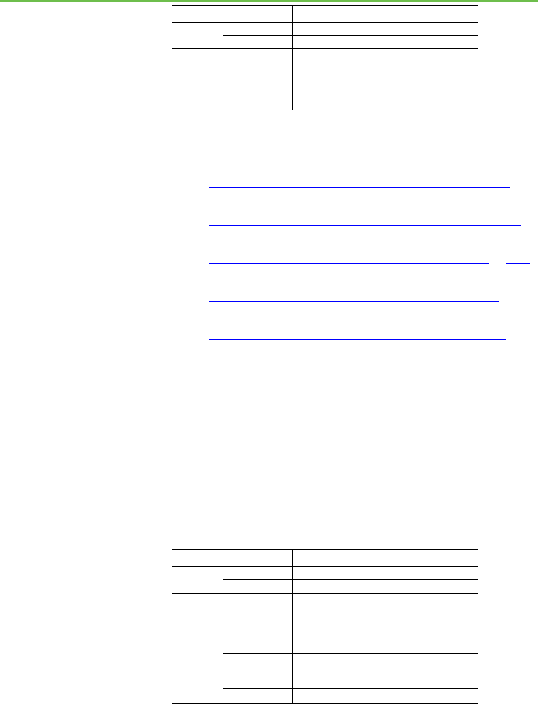
This is an example of Studio 5000 Logix Emulate with a standard emulated
controller, an Operator Training System enabled controller, and two 1789-SIM
I/O modules.
Item
Description
The RSLinx Classic module represents a communication module for the chassis.
By default, the RSLinx Classic module resides in slot 0. Specify a different slot
position when configuring the Virtual Backplane driver in RSLinx Classic.
A Studio 5000 Logix Emulate controller.
An Emulate 5570 OTS controller. This OTS controller is activated in Studio 5000
Logix Emulate for Operator Training and enables a high speed interface for
connectivity to third party Operator Training Systems.
A 1789 simulated I/O module. Clicking the terminal cover of the module opens the
module.
A red box around a module indicates that the module is selected. Right-clicking a
module displays configuration options.
Slots that hold emulated controllers or 1789-SIM I/O modules. Clicking Slot >
Create Module creates a module.
Button that hides slots 9 through 16 to make the display of the virtual chassis
smaller.
See also
Hide slots in the virtual chassis on page 22
Start Studio 5000 Logix
Emulate
Studio 5000 Logix Emulate

Chapter 3 Start the Studio 5000 Logix Emulate application
22 Rockwell Automation Publication LGEM5K-GR016M-EN-E - November 2022
Hide the computer name in the virtual chassis on page 22
Change the update rate on page 22
Keep Studio 5000 Logix Emulate on top on page 23
Hide slots 9-16 if those slots are not in use, or to make the virtual chassis take
up less screen space.
To hide slots in the virtual chassis:
• Click View > Hide Slots 9-16. The slots are hidden in the virtual chassis.
See also
Hide the computer name in the virtual chassis on page 22
Hide the computer name to not display the name at the top of the Studio 5000
Logix Emulate window.
To hide the computer name in the virtual chassis
• Click View > Compact. The Computer box at the top of Studio 5000
Logix Emulate is hidden.
See also
Hide slots in the virtual chassis on page 22
Change the rate at which displayed modules update. The changed rate takes
effect immediately and affects all modules in the virtual chassis.
To change the update rate
• Click Options > Auto Refresh Rate.
• Select the update rate:
• Normal. Update the module display once every second.
• High. Update the module display twice every second.
• Low. Update the module display once every two seconds.
Hide slots in the virtual
chassis
Hide the computer name in
the virtual chassis
Change the update rate

Chapter 3 Start the Studio 5000 Logix Emulate application
Rockwell Automation Publication LGEM5K-GR016M-EN-E - November 2022 23
See also
Configure Studio 5000 Logix Emulate on page 25
Configure the Studio 5000 Logix Emulate window to have it appear on top of
any other windows that may be open on the computer.
To keep Studio 5000 Logix Emulate on top
• Click Options > Always On Top.
See also
Hide slots in the virtual chassis on page 22
Hide the computer name in the virtual chassis on page 22
Keep Studio 5000 Logix
Emulate on top

Rockwell Automation Publication LGEM5K-GR016M-EN-E - November 2022 25
Chapter 4
Configure the Studio 5000 Logix Emulate
application
To configure Studio 5000 Logix Emulate, in the virtual chassis, create a
Studio 5000 Logix Emulate controller, set the speed of the Studio 5000 Logix
Emulate controller, create simulated I/O, and configure trace windows. You
can then change the mode of the Studio 5000 Logix Emulate controller.
See also
Create a Studio 5000 Logix Emulate controller on page 25
Set the speed of time for a Studio 5000 Logix Emulate controller on
page 27
Create a 1789-SIM module in the virtual chassis on page 28
Create a 1756-Module in a Studio 5000 Logix Designer project on page
29
A virtual chassis can have up to 16 emulated controllers at one time. The
performance of the computer may be affected if it runs multiple emulated
controllers simultaneously.
To create a Studio 5000 Logix Emulate controller
1. From the Studio 5000 Logix Emulate window, click Slot > Create
Module.
2. From the Module Type box, select Emulate 55x0 Controller. For
example, select Emulate 5570 Controller.
Tip:
Other controller types such as Emulate 55x0 OTS and Emulate 55x0 SIM
may be available, depending on your license.
3. In the Slot box, select or type the slot where the emulated controller is
to reside. This can be in any slot except the slot occupied by the RSLinx
Classic module.
Tip:
The RSLinx Classic module appears in Slot 0 by default. To place the Studio
5000 Logix Emulate controller in Slot 0, move the RSLinx Classic module to a
slot other than Slot 0.
When changing the project to use a physical Logix5000 controller, make sure
the rack and slot configurations in the project match those in the control
system. Otherwise, proper communication with the physical controller cannot
occur.
Configure Studio 5000 Logix
Emulate
Create a Studio 5000 Logix
Emulate controller
Chapter 4 Configure the Studio 5000 Logix Emulate application
26 Rockwell Automation Publication LGEM5K-GR016M-EN-E - November 2022
4. Click OK to accept the changes and add the emulated controller to the
virtual chassis. Click Cancel to not create the emulated controller.
Tip:
The only modules that function with the emulated controller are the Emulate
55x0 Controller, 1789-SIM 32 Point Input/Output Simulator, Emulate 55x0
OTS, and Emulate 55x0 SIM.
5. If an emulated controller is created in the same slot, and the
configuration for the module is not deleted when the controller is
removed, a prompt appears to use the previous configuration or reset
the configuration to default values:
• To use the previous configuration, click Use the Configuration from
the Previous Controller.
• To reset the configuration, click Reset the Configuration to Default
Values. If the configuration is reset to its default values, the name of
the emulated controller remains the same.
If there was a program in the deleted emulated controller, the
controller name and the date the program was last downloaded into
the controller appear. To load this program into the emulated
controller, select the Load Saved Controller Image from Previous
Instance check box.
Using a previously loaded controller image may result in unexpected operation.
Make sure the program is correct before running emulations.
6. On the General screen, complete:
• Version. Select the version of Studio 5000 Logix Emulate used to
create the project to emulate.
• Startup Mode. Select the startup mode for the controller. Select
either Remote Program or Last Controller State.
• Memory Size. Specify the memory size for the emulated controller.
Make this property equal to the memory size of the controller you
are emulating.
• Periodic Save Interval. Save the current controller information,
including program, data, and configuration information,
periodically. Type the frequency, in minutes. The default is 10
minutes.
• Use RSLinx Classic. Use RSLinx Classic for internal
communications. Clear this check box to use FTLinx for internal
communications. You should clear the check box if you do not
intend to create Emulate controllers with versions 31 and earlier of
the Studio 5000 Logix Emulate application and you want to use
FactoryTalk Linx exclusively. When you create an Emulate controller
using version 31 or earlier, the check box is selected and disabled.
• Enable Periodic Save. Select this option to save the controller
information using the time range entered in the Periodic Save
Interval box.
7. Click Next. The System screen opens.
8. On the System screen, complete:

Chapter 4 Configure the Studio 5000 Logix Emulate application
Rockwell Automation Publication LGEM5K-GR016M-EN-E - November 2022 27
• Continuous Task Dwell Time. Specify the time, in milliseconds,
between the end of the continuous task and the start of the next
execution of the continuous task. This is the time available for all
other Windows applications. The range is 0-100 milliseconds. The
default is 10 milliseconds.
• CPU Affinity. If the emulated controller is running on a computer
that has more than one CPU, set the CPU to run the emulated
controller. The emulated controller can run on one CPU only.
• Channel 0 Serial Port. To emulate serial communications with a
Logix5000 controller, set the computer serial port to emulate
Channel 0 of the Logix5000 controller.
9. Click Finish. The emulated controller appears in the indicated slot of
the virtual chassis.
Tip:
Right-clicking a slot on in the virtual chassis and then clicking Create creates
an emulated controller or module in the slot. The slot number is entered
automatically.
See also
Set the speed of time for a Studio 5000 Logix Emulate controller on
page 27
Set the speed of time to slow down program execution in the emulated
controller. Slowing the speed of time slows down timers and adds additional
time to the program scan time. This allows for more time to observe program
execution as it occurs.
The speed of time is set as a percentage of real time. When the speed of time is
set to 100%, program execution occurs in real time. Setting the speed of time
to another value slows program execution by an amount proportional to the
selected percentage. For example, setting the speed of time to 60 percent
makes actions that normally take one second take approximately 1.67 seconds.
Changes to the speed of time take effect immediately.
To set the speed of time for a Studio 5000 Logix Emulate controller
1. Right-click the emulated controller and then click Configure
Emulation. The Configure Emulation window opens.
Tip:
The Configuration Emulation window cannot open for Operator Training
controllers.
2. Under the Speed of Time area at the top of the window, drag the slider
to adjust the speed of time in one percent increments or enter the
percentage manually in the available % box in the lower right corner of
the Speed of Time area.
Set the speed of time for a
Studio 5000 Logix Emulate
controller

Chapter 4 Configure the Studio 5000 Logix Emulate application
28 Rockwell Automation Publication LGEM5K-GR016M-EN-E - November 2022
3. Click Confirm Time % Change. The % box in the lower left corner of
the Speed of Time area indicates the last value set for the speed of
time.
Tips:
• To set the speed of time to 100% without dragging the slider or entering
a value, click 100% NOW.
• To set the speed of time to 0% without dragging the slider or entering a
value, click 0% NOW. Setting the speed of time to 0% stops program
execution.
See also
Create a Studio 5000 Logix Emulate controller on page 25
Create simulated I/O on page 28
To create simulated I/O, create a 1789-SIM module in the virtual chassis, and a
1756-Module in the Studio 5000 Logix Designer project.
See also
Create a 1789-SIM module in the virtual chassis on page 28
Create a 1756-Module in a Studio 5000 Logix Designer project on page
29
Use a simulated I/O module (1789-SIM) to simulate discrete I/O with Studio
5000 Logix Emulate. This is the only form of I/O that Studio 5000 Logix
Emulate simulates. This module resides in the virtual chassis and provides
inputs and outputs to use in logic programs.
• In Studio 5000 Logix Designer, the simulated I/O module is called
1756-Module.
• In Studio 5000 Logix Emulate, the simulated I/O module is called
1789-SIM.
To create a 1789-SIM module in the virtual chassis
1. In the virtual chassis, click Slot > Create Module.
2. In the Select Module window, from the Module Type list, select
1789-SIM 32 Point Input/Output Simulator.
3. In the Slot box, select or type the slot number for the SIM module, and
then click OK. The Select Device window opens and displays the slot
number for the module.
4. If a 1789-SIM module is deleted from this slot without clearing its
configuration, a message appears stating that previous configuration
information exists for the module. To retain the previous
Create simulated I/O
Create a 1789-SIM module in
the virtual chassis

Chapter 4 Configure the Studio 5000 Logix Emulate application
Rockwell Automation Publication LGEM5K-GR016M-EN-E - November 2022 29
configuration, click Use the Previous Configuration. To reset the
module to its default values, click Reset the Configuration to Default
Values.
5. Click Next. The General window opens.
6. In the Label for 1789-SIM Module Marquee box, type the name of the
SIM module so that the name scrolls across the face of the module.
This helps identify the module while it is in the virtual chassis. When
not entering a name, Studio 5000 Logix Emulate uses Simulator Module
by default.
Tip:
Another method for simulating I/O is to use another emulated controller to
produce and consume tags.
See also
Create a 1756-Module in a Studio 5000 Logix Designer project on page
29
Create a simulated module in the Studio 5000 Logix Designer project. The
simulated I/O module in Studio 5000 Logix Designer is called 1756-Module.
This module is called 1789-SIM in the virtual chassis.
To create a 1756-Module in a Studio 5000 Logix Designer project
1. In the Studio 5000 Logix Designer Controller Organizer, right-click
the I/O Configuration folder, and then click New Module.
2. In the Select Module Type dialog box, type 1756-Module in the Search
box.
3. From the Modules list, select 1756-Module, and then click Create.
4. In the New Module window, enter these parameters for the module:
• Name. The name of the module.
• Description (optional). The function of the module in the system.
• Comm Format. The type of I/O in simulation.
• Slot. The slot in the virtual chassis of the module.
5. In the New Module dialog box, specify the connection parameters for
the module:
Read/write connections:
Listen only connections:
Input Assembly Instance
1
Input Assembly Instance
1
Input Size
2
Input Size
2
Output Assembly Instance
2
Output Assembly Instance
3
Output Size
1
Output Size
1
Configuration Assembly Instance
16
Configuration Assembly Instance
16
Configuration Size
0
Configuration Size
0
6. Click OK. Another Module Properties window opens.
7. Specify the Requested Packet Interval (RPI).
Create a 1756-Module in a
Studio 5000 Logix Designer
project

Chapter 4 Configure the Studio 5000 Logix Emulate application
30 Rockwell Automation Publication LGEM5K-GR016M-EN-E - November 2022
Tip:
Enter at least 50.0 ms for the RPI. The connection fails if the RPI is less
than 50 ms. This 1756-Module uses the generic module profile with a
default RPI of 5.0 milliseconds. This value must change.
8. Click OK.
See also
Create a 1789-SIM module in the virtual chassis on page 28
Remove either an emulated controller or a 1789-SIM module from the virtual
chassis. Removal of a module cannot be undone. Recreate the module.
To remove a module
1. Open the virtual chassis.
2. Click Slot > Remove Module.
3. In the Remove Module dialog box, in the Slot field, select or type the
slot location for the module to remove and then click OK. A prompt
appears to confirm the removal of the module.
4. Click OK to remove the module from the virtual chassis.
Tips:
• Right-clicking the module and clicking Remove also removes the module.
• When removing an emulated controller, remove the emulated controller and
leave its configuration in place, or remove both the emulated controller and
its configuration. To remove the emulated controller and its configuration,
right-click the emulated controller, select Remove, select the Clear module
configuration check box, and then click OK.
See also
Hide slots in the virtual chassis on page 22
Clear the configuration of the virtual chassis on page 30
Automatically clear the configuration of the virtual chassis upon deleting a
module. This resets the configuration of the virtual chassis to the default
settings. It also deletes the Saved Controller Image file and External Routine
DLLs.
To clear the configuration of the virtual chassis
• From the virtual chassis, click Options > Clear Configuration on
Remove. The Clear module configuration check box is now
automatically selected when deleting a module.
Remove a module
Clear the configuration of
the virtual chassis

Chapter 4 Configure the Studio 5000 Logix Emulate application
Rockwell Automation Publication LGEM5K-GR016M-EN-E - November 2022 31
See also
Studio 5000 Logix Emulate on page 21
When tracepoint and breakpoint instructions execute, a trace window opens.
Tracepoint and breakpoint instructions are programmed in the Studio 5000
Logix Designer project. Configure how the traces are handled. The
Configuration Emulation window cannot open for Operator Training
controllers.
To configure trace windows
1. In the virtual chassis, right-click the emulated controller with the
configuration to display, and then click Configure Emulation. The
Configuration Emulation window opens.
2. Configure these settings:
Setting:
Description:
Ignore If No Value Changed Toggle between recording every trace and only
recording traces where there are changes to the values.
If traces where no value is changed are ignored, the
trace windows do not show traces where the value is not
changed.
TimeStamp
Determine how time is recorded in traces:
• None. Record no time information in the trace
windows.
• Delta. Record the difference between the current
trace and the last trace for that particular trace
window. The first trace for the window always shows
0 milliseconds.
• Absolute. Records the time that the trace triggered.
The time is in the number of milliseconds since the
emulated controller was last changed to the Run
mode.
Selecting a time stamp mode and changing the mode
while a trace window is open results in subsequent
traces using the new time stamp mode.
Display all new traces
Display all new traces in a trace window automatically.
Log new traces to disk
Automatically log new traces to disk.
Display All Traces
Used to display all of the current traces in their trace
windows. The current traces are listed by name in the
Configure Emulation window.
Close All Traces
Close all of the open trace windows.
Remove All Traces
Remove all of the current traces from the trace list.
Close Log File
Stop logging traces to a file.
Trace Log File
The currently set log file. Browse to set a different log
file.
See also
Work with trace windows on page 63
Configure trace windows

Chapter 4 Configure the Studio 5000 Logix Emulate application
32 Rockwell Automation Publication LGEM5K-GR016M-EN-E - November 2022

Rockwell Automation Publication LGEM5K-GR016M-EN-E - November 2022 33
Chapter 5
Change the mode of an emulated controller
The Studio 5000 Logix Emulate controllers support the modes of Logix5000
controllers. If you have multiple Studio 5000 Logix Emulate controllers within
the virtual chassis, you can change the mode of all of the controllers in the
chassis simultaneously. Changing the mode of multiple controllers at one
time may be beneficial in depicting your application.
Tip:
With the exception of Single Scan mode, you can set the mode of the
emulated controller through either Studio 5000 Logix Emulate or Studio 5000
Logix Designer. To set the mode in Studio 5000 Logix Designer, click
Communications and select the mode.
See also
Change a Logix Emulate controller to Program mode on page 33
Change a Logix Emulate controller to Run mode on page 34
Change a Logix Emulate controller to Remote mode on page 35
Emulator Controller Status Indicators on page 36
Change a single Studio 5000 Logix Emulate controller in the virtual chassis to
Program mode. This mode allows the programing of the emulated controller.
To change a Studio 5000 Logix Emulate controller to Program mode
• In the virtual chassis, right-click the emulated controller and select
Program. The controller transitions to Program mode.
See also
Change all Studio 5000 Logix Emulate controllers to Program mode on
page 34
Change a Studio 5000 Logix Emulate controller to Run mode on page
34
Set the mode of a Studio 5000 Logix Emulate controller to Single Scan
on page 35
Emulator Controller Status Indicators on page 36
Change the mode of a
Studio 5000 Logix Emulate
controller
Change a Studio 5000 Logix
Emulate controller to
Program mode

Chapter 5 Change the mode of an emulated controller
34 Rockwell Automation Publication LGEM5K-GR016M-EN-E - November 2022
Change all of the Studio 5000 Logix Emulate controllers in the virtual chassis
to Program mode. This mode allows programming of the emulated
controllers.
To change all Studio 5000 Logix Emulate to Program mode
1. Click All Modules > Program. The Program Mode dialog box opens.
Tip:
By default, all slots that contain emulated controllers in the virtual chassis
appear selected. To not change all of the emulated controllers to Program
mode, clear the slots of the emulated controllers to not place in Program
mode.
2. Click OK. The specified emulated controllers transition to Program
mode.
See also
Change all Studio 5000 Logix Emulate controllers to Run mode on
page 35
Emulator Controller Status Indicators on page 36
Change an individual Studio 5000 Logix Emulate controller or all emulated
controllers in the virtual chassis to Run mode in order to run the logic
program.
To change a Studio 5000 Logix Emulate controller to Run mode
• In the virtual chassis, right-click the emulated controller and select
Run. The controller transitions to Run mode.
See also
Change all Studio 5000 Logix Emulate controllers to Run mode on
page 35
Change a Studio 5000 Logix Emulate controller to Program mode on
page 33
Set the mode of a Studio 5000 Logix Emulate controller to Single Scan
on page 35
Emulator Controller Status Indicators on page 36
Change all Studio 5000
Logix Emulate controllers to
Program mode
Change a Studio 5000 Logix
Emulate controller to Run
mode

Chapter 5 Change the mode of an emulated controller
Rockwell Automation Publication LGEM5K-GR016M-EN-E - November 2022 35
Change all Studio 5000 Logix Emulate controllers in the virtual chassis to Run
mode in order to run the logic programs.
To change all Studio 5000 Logix Emulate controllers to Run mode
1. Click All Modules > Run. The Run Mode dialog box opens.
Tip:
By default, all slots that contain emulated controllers in the virtual chassis
appear selected. To not change all of the emulated controllers to Run mode,
clear the slots of the emulated controllers to not place in Run mode.
2. Click OK. The specified emulated controllers transition to Run mode.
See also
Change a Studio 5000 Logix Emulate controller to Run mode on page
34
Change all controllers to Program mode on page 34
Emulator Controller Status Indicators on page 36
Change a Studio 5000 Logix Emulate controller to Remote mode so that a
software application, such as Studio 5000 Logix Designer, can change the
mode of the emulated controller.
To change a Studio 5000 Logix Emulate controller to Remote mode
• In the virtual chassis, right-click the emulated controller and select
Remote. The controller transitions to Remote mode.
See also
Change a Studio 5000 Logix Emulate controller to Program mode on
page 33
Change a Studio 5000 Logix Emulate controller to Run mode on page
34
Connect to a Studio 5000 Logix Emulate controller from a remote
computer on page 41
Emulator Controller Status Indicators on page 36
Set the mode of the Studio 5000 Logix Emulate controller to Single Scan
mode to run through the logic programs once to view the results. Single Scan
mode is not available in physical controllers. Set each emulated controller to
Single Scan mode individually.
Change all Studio 5000
Logix Emulate controllers to
Run mode
Change a Studio 5000 Logix
Emulate controller to
Remote mode
Set the mode of a Studio
5000 Logix Emulate
controller to Single Scan

Chapter 5 Change the mode of an emulated controller
36 Rockwell Automation Publication LGEM5K-GR016M-EN-E - November 2022
To set the mode of a Studio 5000 Logix Emulate controller to Single
Scan
• Right-click the emulated controller in the virtual chassis and select
Single Scan.
Tip:
When the mode of the emulated controller is set to Single Scan and is
placed in Run mode and the single scan completes, a prompt appears to
either run the emulated controller continuously or perform a single scan
again.
See also
Change a Studio 5000 Logix Emulate controller to Program mode on
page 33
Change a Studio 5000 Logix Emulate controller to Run mode on page
34
The controller has these indicators.
• Module display status
• Mode display
• Key switch
Controller Status Indicators and Display
Indicator
Status
Description
RUN
Off
The controller is in any mode but Run mode.
Solid green
The controller is in Run mode.
I/O
Off
Either:
• There are no devices in the I/O configuration of the
controller.
• The controller does not contain a project. The
controller memory is empty.
Solid green The controller is communicating with all the devices in
its I/O configuration.
Flashing green
One or more devices in the I/O configuration of the
controller are not responding.
Flashing red
A virtual chassis error was detected. Contact your
Rockwell Automation representative or local distributor
FRC
Off No tags contain I/O force values.
I/O forces are inactive (disabled).
Flashing amber
At least one tag contains an I/O force value.
I/O force values are inactive (disabled).
Solid amber
I/O forces are active (enabled).
I/O force values may or may not exist.
RS232
(1)
Off
No COM port was selected.
Solid green
The selected COM port was successfully assigned to
channel 0 of the controller.
Solid red There is a COM port conflict or you selected an invalid
COM port number.
BAT
(1)
Off
Normal operation.
Emulator Controller Status
Indicators
Chapter 5 Change the mode of an emulated controller
Rockwell Automation Publication LGEM5K-GR016M-EN-E - November 2022 37
Indicator
Status
Description
Flashing amber
The controller is in Power-up mode.
Solid red
Persistent storage for the controller has failed.
OK
Solid red
The controller detected a major fault.
Go online, and clear the fault.
If the OK status indicator remains solid red, contact your
Rockwell Automation representative or local distributor.
Solid green
The controller is OK.
1. Note that the behavior of these status indicators are unique to Emulate controllers.
See also
Change a Studio 5000 Logix Emulate controller to Program mode on
page 33
Change all Studio 5000 Logix Emulate controllers to Program mode on
page 34
Change a Studio 5000 Logix Emulate controller to Run mode on page
34
Change all Studio 5000 Logix Emulate controllers to Run mode on
page 35
Change a Studio 5000 Logix Emulate controller to Remote mode on
page 35
The 1789-SIM module has these indicators.
• Module display
• Module status indicators
Simulator Module Status Indicators and Display
Customize the scrolling display when creating the module or by editing the
properties of the module. The display functions as a label and does not provide
status information.
Indicator
Status
Description
OK
Off
The module is not operating normally.
Green
The module is operating normally.
I/O
Off Either:
• There are no devices in the I/O configuration of an
operating controller.
• The controller does not contain a project. The
controller memory is empty.
Blinking green
The SIM module exists in the I/O configuration of an
operating controller. The SIM module is communicating,
but the controller is not in Run mode.
Solid green The SIM module exists in the I/O configuration of an
Simulator Module Status
Indicators
Chapter 5 Change the mode of an emulated controller
38 Rockwell Automation Publication LGEM5K-GR016M-EN-E - November 2022
Indicator
Status
Description
operating controller. The SIM module is communicating
and the controller is in Run mode.
See also
Change a Studio 5000 Logix Emulate controller to Program mode on
page 33
Change all Studio 5000 Logix Emulate controllers to Program mode on
page 34
Change a Studio 5000 Logix Emulate controller to Run mode on page
34
Change all Studio 5000 Logix Emulate controllers to Run mode on
page 35
Change a Studio 5000 Logix Emulate controller to Remote mode on
page 35

Rockwell Automation Publication LGEM5K-GR016M-EN-E - November 2022 39
Chapter 6
Connect an emulated controller to Studio 5000
Logix Designer
To connect the Studio 5000 Logix Emulate controller to Studio 5000 Logix
Designer, requires:
• Creating a communications driver in either RSLinx Classic or RSLinx
Classic Lite and specifying a slot number for the emulated controller.
• Setting the Studio 5000 Logix Designer project to use the emulated
controller.
• Configuring communications in the Studio 5000 Logix Designer to use
the communications driver.
• Adding the simulated I/O to the Studio 5000 Logix Designer project.
• Programing breakpoint and tracepoint instructions.
Tip:
Connect to a Studio 5000 Logix Emulate controller from a remote
computer.
See also
Create a communications driver for a Studio 5000 Logix Emulate
controller on page 39
Configure a Studio 5000 Logix Designer project to use the Studio 5000
Logix Emulate controller on page 40
Configure communications in the Studio 5000 Logix Designer project
on page 41
Create simulated I/O on page 28
Program breakpoints and tracepoints on page 51
Before communicating with a Studio 5000 Logix Emulate controller using
Studio 5000 Logix Designer, create a communication driver for the emulated
controller using RSLinx Classic. Other applications can then communicate
with the emulated controller.
Connect a Studio 5000
Logix Emulate controller to
Studio 5000 Logix Designer
Create a communications
driver for a Studio 5000
Logix Emulate controller

Chapter 6 Connect an emulated controller to Studio 5000 Logix Designer
40 Rockwell Automation Publication LGEM5K-GR016M-EN-E - November 2022
To create a communications driver for a Studio 5000 Logix Emulate
controller
1. In RSLinx Classic, click Communications > Configure Drivers. The
Configure Drivers window appears.
2. From the Available Driver Types list, select the Virtual Backplane
(SoftLogix 58xx, USB) driver.
3. Click Add New. The Add New RSLinx Driver dialog box opens.
4. Accept the default name of the driver, or type a name up to 15
characters, and then click OK. The Configure Virtual Backplane
window opens.
5. In the Slot Number box, specify the slot number where the emulated
controller is to reside and click OK. The default slot number is slot 0.
6. When the new driver appears in the Configured Drivers list, click
Close.
See also
Configure communications in the Studio 5000 Logix Designer project
on page 41
Connect a Studio 5000 Logix Emulate controller from a remote
computer on page 41
Before emulating a project, configure the Studio 5000 Logix Designer project
to use the emulated controller.
To configure a Studio 5000 Logix Designer project to use the Studio
5000 Logix Emulate controller
1. In Studio 5000 Logix Designer, open the project to emulate.
2. Click Edit > Controller Properties. The Controller Properties window
opens.
3. On the General tab, set the Slot box to correspond with the slot in the
virtual chassis that contains the emulated controller.
4. Click Change Controller. The Change Controller Type dialog box
opens.
5. From the Type list, select Emulate 55x0 Controller.
6. In the Revision box, click the revision number for the emulated
controller, and then click OK.
Configure a Studio 5000
Logix Designer project to
use the Studio 5000 Logix
Emulate controller

Chapter 6 Connect an emulated controller to Studio 5000 Logix Designer
Rockwell Automation Publication LGEM5K-GR016M-EN-E - November 2022 41
See also
Create a communications driver for a Studio 5000 Logix Emulate
controller on page 39
Configure communications in the Studio 5000 Logix Designer project
on page 41
Before downloading to or going online with the Studio 5000 Logix Emulate
controller, configure communications in the Studio 5000 Logix Designer
project to set the communication path to use the emulated controller.
To configure communications in the Studio 5000 Logix Designer
project
1. In Studio 5000 Logix Designer, open the project to emulate.
2. Click Communications > Who Active. The Who Active window
displays the available network nodes that use the communication
drivers configured in RSLinx Classic.
3. In the tree, click the emulated controller to use for this project.
4. Click Set Project Path.
See also
Create a communications driver for a Studio 5000 Logix Emulate
controller on page 39
Connect a Studio 5000 Logix Emulate controller from a remote
computer on page 41
Remote computers can connect to a computer running Studio 5000 Logix
Emulate. This allows use of programs such as Studio 5000 Logix Designer and
FactoryTalk Batch from a computer other than the one running the Studio
5000 Logix Emulate controller. This allows uploading, downloading, and
editing online as if Studio 5000 Logix Designer is running locally.
To make this type of connection, use RSLinx Classic on the remote computers
to connect to the computer running Studio 5000 Logix Emulate.
To connect a Studio 5000 Logix Emulate controller from a remote
computer
• Use RSLinx Classic on the remote computer to connect to the
computer running Studio 5000 Logix Emulate.
Configure communications
in a Studio 5000 Logix
Designer project
Connect a Studio 5000
Logix Emulate controller
from a remote computer

Chapter 6 Connect an emulated controller to Studio 5000 Logix Designer
42 Rockwell Automation Publication LGEM5K-GR016M-EN-E - November 2022
See also
Connect a Studio 5000 Logix Emulate controller to a FactoryTalk View
project through FactoryTalk Linx on page 43
Connect a Studio 5000 Logix Emulate controller to a FactoryTalk View
project through OPC on page 47

Rockwell Automation Publication LGEM5K-GR016M-EN-E - November 2022 43
Chapter 7
Connect an emulated controller to a FactoryTalk
View project through RSLinx Enterprise
Use either FactoryTalk® Linx or RSLinx Classic to connect the Studio 5000
Logix Emulate controller to FactoryTalk View ME or FactoryTalk View SE
projects. Both methods use OLE for Process Control (OPC) to communicate.
However, it is easier to use FactoryTalk Linx to create the necessary
connections.
Using FactoryTalk Linx to connect the Studio 5000 Logix Emulate controller
to a FactoryTalk View ME or FactoryTalk View SE project requires installing
FactoryTalk Linx on both the computer running the Studio 5000 Logix
Emulate controller and on the computer running FactoryTalk View ME or
FactoryTalk View SE.
FactoryTalk Linx uses FactoryTalk to automatically connect tags for Rockwell
Automation applications. Once FactoryTalk Linx is installed and configured, it
is not necessary to configure anything else to use tags from the Studio 5000
Logix Emulate controller in FactoryTalk View ME and FactoryTalk View SE
projects. Once a tag is used in Logix Emulate, the tag becomes available to
FactoryTalk View ME or FactoryTalk View SE.
For information about using RSLinx Classic to create those connections, see
the FactoryTalk View ME or FactoryTalk View SE documentation.
After configuring the FactoryTalk Linx server for a FactoryTalk View ME or
FactoryTalk View SE project, browse for tags from the Studio 5000 Logix
Emulate controller.
See also
Connect a Studio 5000 Logix Emulate controller to a FactoryTalk View
ME or FactoryTalk View SE project through OPC on page 47
For FactoryTalk View SE projects, FactoryTalk Linx must be installed on both
the computer running FactoryTalk View SE and the computer running Studio
5000 Logix Emulate. Both computers must use the same FactoryTalk
Directory. If Studio 5000 Logix Emulate and FactoryTalk View SE are installed
on different computers, both computers must use the same network
Directory.
Connect a Studio 5000
Logix Emulate controller to
a FactoryTalk View project
through FactoryTalk Linx
Prerequisites
Chapter 7 Connect an emulated controller to a FactoryTalk View project through RSLinx Enterprise
44 Rockwell Automation Publication LGEM5K-GR016M-EN-E - November 2022
Tip:
Install FactoryTalk Linx and the FactoryTalk® Services Platform from the
FactoryTalk View ME or FactoryTalk View SE installation disks.
For FactoryTalk View ME projects, FactoryTalk Linx, Studio 5000 Logix
Emulate, and FactoryTalk View ME must be installed on the same computer.
In this case, the FactoryTalk Directory used must be the local Directory.
FactoryTalk View ME does not support using a network Directory.
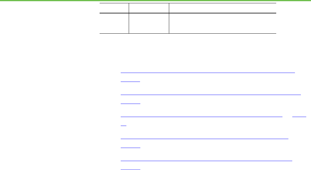
This example depicts a FactoryTalk Linx module in the virtual chassis.
Item
Description
The RSLinx Classic module represents a communication module for the chassis.
By default, the RSLinx Classic module resides in slot 0. Specify a different slot
position when configuring the Virtual Backplane driver in RSLinx Classic.
When Studio 5000 Logix Emulate runs on a computer that is also running
FactoryTalk Linx, a FactoryTalk Linx module occupies the first unoccupied slot in
the chassis. This module cannot be removed unless FactoryTalk Linx is
uninstalled. Specify a different slot position by editing the Virtual Backplane
properties in FactoryTalk Administration Console.
See also
Configure a FactoryTalk Linx server for Studio 5000 Logix Emulate on
page 44
Create a FactoryTalk Linx server for Studio 5000 Logix Emulate to connect
the emulated controller to a FactoryTalk View ME or FactoryTalk View SE
project through FactoryTalk Linx.
To configure a FactoryTalk Linx server for Studio 5000 Logix
Emulate
1. Make sure the Studio 5000 Logix Emulate controller is in Run mode.
2. Open the FactoryTalk View SE or FactoryTalk View ME project.
3. In the FactoryTalk View Explorer tree, right-click the area to create
the FactoryTalk Linx data server in the project, and then click Add New
Server > Rockwell Automation Device Server (FactoryTalk Linx).
Tip:
The server can exist in the root of the FactoryTalk View ME or FactoryTalk
View SE project.
4. Type a name for the FactoryTalk Linx server in the Name box, or type a
description for the server in the Description box.
5. In the Computer hosting the FactoryTalk Linx server box, type the
name of the computer running Studio 5000 Logix Emulate. If this
computer is the same as the computer that is running FactoryTalk
View ME and FactoryTalk View SE, type the name of that computer or
type localhost.
FactoryTalk Linx module in
the virtual chassis
Configure a FactoryTalk
Linx server for Studio 5000
Logix Emulate

Chapter 7 Connect an emulated controller to a FactoryTalk View project through RSLinx Enterprise
Rockwell Automation Publication LGEM5K-GR016M-EN-E - November 2022 45
Tip:
For FactoryTalk View ME systems, localhost is the only possible name for
the computer that is hosting the FactoryTalk Linx server.
6. In the Explorer tree of the FactoryTalk View ME or FactoryTalk View
SE project, select the FactoryTalk Linx server and click
Communication Setup. The Communication Setup window opens.
7. Create a device shortcut to the emulated controller to identify which
tags are coming from the emulator in the FactoryTalk View ME and
FactoryTalk View SE Tag Browser.
8. Click Add, and then type a name for the shortcut to appear in the
FactoryTalk View ME or FactoryTalk View SE Tag Browser.
9. Click Apply.
10. When prompted to apply changes, click Yes. The shortcut is associated
with the emulator.
11. Click OK to close the Communication Setup window.
See also
FactoryTalk Linx module in the virtual chassis on page 44
Tag Browser in FactoryTalk View ME or FactoryTalk View SE on page
45
This is an example of the Tag Browser in FactoryTalk View ME or FactoryTalk
View SE from which to browse for tags from the FactoryTalk Linx server. For
more information about browsing for tags in a FactoryTalk View project, see
the documentation for FactoryTalk View ME or FactoryTalk View SE.
• The shortcut in the FactoryTalk Linx server Communication Setup
window has a corresponding folder at the root level of the FactoryTalk
View ME or FactoryTalk View SE Tag Browser.
• The Online folder contains controller tags.
• Folders for each program file contain program tags.
See also
Configure a tag in a FactoryTalk View project on page 49
Tag Browser in FactoryTalk
View ME or FactoryTalk
View SE

Rockwell Automation Publication LGEM5K-GR016M-EN-E - November 2022 47
Chapter 8
Connect an emulated controller to a FactoryTalk
View project through OPC
Studio 5000 Logix Emulate uses OLE for Process Control (OPC) to
communicate with FactoryTalk View ME and FactoryTalk View SE.
Connecting the Studio 5000 Logix Emulate controller to a FactoryTalk View
project requires creating an OPC topic in RSLinx Classic and creating a
communications node and tags in the FactoryTalk View ME or FactoryTalk
View ME project that uses the OPC topic.
See the FactoryTalk View ME and FactoryTalk View SE documentation for
more information.
See also
Connect a Studio 5000 Logix Emulate controller to a FactoryTalk View
project through FactoryTalk Linx on page 43
Use RSLinx Classic Single Node, RSLinx Classic OEM, or FactoryTalk Linx
Gateway to create the OPC topic. RSLinx Classic Lite does not support OPC
communication. For more information about using RSLinx Classic, see the
RSLinx Classic documentation.
To create an OPC topic for a Studio 5000 Logix Emulate controller
1. Open Studio 5000 Logix Emulate and verify that the emulated
controller is running.
2. In RSLinx Classic, click Communications > RSWho to open the
RSWho window.
Tip:
The Studio 5000 Logix Emulate controller should be visible in the RSWho
window. If it is not, make sure there is a communication driver for the
emulated controller.
3. In the RSWho window, right-click the Studio 5000 Logix Emulate
controller and select Configure New DDE/OPC Topic. The DDE/OPC
Topic Configuration window opens with the new topic.
4. Click Done to close the DDE/OPC Topic Configuration window and
save the topic.
Connect a Studio 5000
Logix Emulate controller to
a FactoryTalk View project
through OPC
Create an OPC topic for a
Studio 5000 Logix Emulate
controller

Chapter 8 Connect an emulated controller to a FactoryTalk View project through OPC
48 Rockwell Automation Publication LGEM5K-GR016M-EN-E - November 2022
See also
Create a communications driver for a Studio 5000 Logix Emulate
controller on page 39
Create a communications node in a FactoryTalk View ME or FactoryTalk View
SE that uses the OPC topic for the Studio 5000 Logix Emulate controller. The
OPC topic is required to communicate between RSLinx Classic and
FactoryTalk View ME or FactoryTalk View SE.
Create a communications node in a FactoryTalk View project
1. Open the FactoryTalk View ME or FactoryTalk View SE project.
2. In the System folder of the project, open the Node editor.
Tip:
In FactoryTalk View ME or FactoryTalk View SE, a node represents a
communications device. This device is usually a programmable controller
or another Windows application.
3. In the Data Source section, select OPC Server.
4. In the Name box, type a name for the node that represents the Studio
5000 Logix Emulate controller.
5. Select the Enabled check box.
6. In Name box of the Server section, browse to select one:
• RSLinx OPC Server. Select if the Studio 5000 Logix Emulate
controller is running on the same computer as FactoryTalk View SE.
• RSLinx Remote OPC Server. Select if the Studio 5000 Logix
Emulate controller is not running on the same computer as
FactoryTalk View SE.
7. After Type, select an option:
• In-Process. Select if the Studio 5000 Logix Emulate controller is
running on the same computer as FactoryTalk View ME or
FactoryTalk View SE.
• Remote. Select if the Studio 5000 Logix Emulate controller is not
running on the same computer as FactoryTalk View ME or
FactoryTalk View SE, and then enter the name of the computer that
is running the emulated controller in the Server Computer Name or
Address box.
8. Leave the Access Path box blank.
9. To change to a faster or slower update rate, enter the frequency in the
Update Rate box. The default is 1 second.
10. Click Accept to save the node configuration.
Create a communications
node in a FactoryTalk View
project

Chapter 8 Connect an emulated controller to a FactoryTalk View project through OPC
Rockwell Automation Publication LGEM5K-GR016M-EN-E - November 2022 49
See also
Create an OPC topic for a Studio 5000 Logix Emulate controller on
page 47
Configure a tag in a FactoryTalk View project on page 49
After creating an OPC node for the Studio 5000 Logix Emulate controller, add
tags from the Studio 5000 Logix Designer project to the FactoryTalk View ME
or FactoryTalk View SE tag database.
To configure a tag in a FactoryTalk View project
1. Open the FactoryTalk View ME or FactoryTalk View SE project.
2. In the System folder of the project, open the Tag Database editor.
3. In the Tag section, click the Type list to select the type of tag to create.
4. In the Data Source section, select Device.
5. In the Node Name box, browse to open the Node Browser dialog box,
select the OPC node created for the emulated controller, and then click
OK.
6. In the Address box, browse to open the OPC Address Browser dialog
box, select the address to use with the tag, and then click OK.
7. Finish adding the tag by completing:
• Name. The name of the tag.
• Security. If security for the FactoryTalk View ME or FactoryTalk
View SE project is set up, select the security class associated with the
tag.
• Description (optional). A description of the tag.
• Minimum. The minimum value for the tag used in FactoryTalk View
ME or FactoryTalk View SE.
• Maximum. The maximum value for the tag used in FactoryTalk
View ME or FactoryTalk View SE.
• Scale. The scaling value for the tag.
• Offset. The value to add to the tag.
• Units. Type the units for the tag.
• Data Type. The data type for the tag.
8. Click Accept to store the tag in database. The tag is now ready for use
in the FactoryTalk View ME or FactoryTalk View SE project.
See also
Tag Browser in FactoryTalk View ME or FactoryTalk View SE on page
45
Create a communications node in a FactoryTalk View project on page
48
Configure a tag in a
FactoryTalk View project

Rockwell Automation Publication LGEM5K-GR016M-EN-E - November 2022 51
Chapter 9
Breakpoint and tracepoint instructions
Breakpoint and tracepoint instructions monitor the state of the logic when
the logic is in specified conditions. When a rung is true, breakpoints stop
program emulation, and tracepoints log specified data.
Tip:
Breakpoint and tracepoint instructions are supported only in ladder
diagram programs running in Studio 5000 Logix Emulate. These
instructions are not supported by physical Logix5000 controllers.
See also
Program a BPT instruction on page 52
Example BPT instruction on page 52
Program a TPT instruction on page 54
Example TPT instruction on page 54
Breakpoints are programmed with the breakpoint (BPT) instruction. When
the inputs on a rung containing a BPT instruction are true, the BPT
instruction stops executing the program. A prompt appears when the
breakpoint triggers. The values that triggered the breakpoint are indicated.
The title bar of the dialog box shows the slot that contains the Studio 5000
Logix Emulate controller that encountered the breakpoint.
Acknowledging the prompt makes the Studio 5000 Logix Emulate controller
resume program execution. If the conditions that triggered the breakpoint are
not changed, the breakpoint triggers again. A trace window opens for the
breakpoint to show information about the breakpoint and the values it traced.
Tip:
When a breakpoint triggers, the project is not editable until the execution is
permitted to continue. The Studio 5000 Logix Emulate controller can go online
so you can observe the state of the project, but the project is not editable.
Trying to accept a rung edit while a breakpoint is triggered prompts that the
controller is not in the correct mode.
See also
Breakpoint trace window on page 53
Example BPT instruction on page 52
Program breakpoints and
tracepoints
Breakpoints
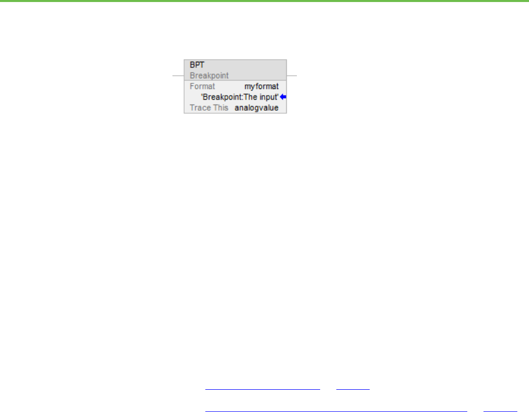
Chapter 9 Breakpoint and tracepoint instructions
52 Rockwell Automation Publication LGEM5K-GR016M-EN-E - November 2022
This is an example rung that contains a BPT instruction that stops program
execution when an analog value is greater than 3.02 or less than 2.01 as
specified in the GEQ and LEQ instructions.
The BPT instruction contains:
• The Breakpoint (BPT) instruction identifier
• The Format parameter. The value in this parameter specifies the
format of the breakpoint information to be displayed. In this example,
the format is myformat.
• The full string of the format is: Breakpoint:The input value is %f.
• The characters before the colon (Breakpoint) appear in the title
bar of the trace window. The characters that appear after the
colon (%f) represent the value of the tag to be traced.
• The Trace This parameter. The value in this parameter is the tag to be
traced. In this example, there is only one tag to be traced and that tag
is analogvalue.
See also
Breakpoint trace window on page 53
String formats for tracepoint and breakpoint instructions on page 55
To program the BPT instruction, set the format of text to display in the trace
window for the breakpoint, as well as the tag value display in the trace
window.
To program a BPT instruction
• In the BPT instruction, these two parameters:
• Format. Enter a string to format the text to appear in the trace
window for the breakpoint. A string tag is required. For example:
Breakpoint:The input value is %f
• Trace This. Enter the tag that has the value to display in the trace
window. An INT, BOOL, SINT, DINT, or REAL tag is required. For
example:
analogvalue
Example BPT instruction
Program a BPT instruction

Chapter 9 Breakpoint and tracepoint instructions
Rockwell Automation Publication LGEM5K-GR016M-EN-E - November 2022 53
Tips:
• Tag structures are not traceable. For example, tracing entire timers or
counters is not supported. Trace individual structure members.
• Display a large number of tag values with the BPT instruction. The
formatting string can contain only 82 characters. Two characters are
required in the formatting string for each tag to be in the breakpoint. The
maximum number of tags traceable with a single BPT instruction is 41.
Including spaces and other formatting to separate tag data in traces can
significantly reduce the number of tag values that the BPT instruction can
display effectively.
See also
String formats for tracepoint and breakpoint instructions on page 55
Example BPT instruction on page 52
The trace window that opens for the example BPT instruction includes:
• The title bar includes the Slot number that contains the Studio 5000
Logix Emulate controller that has the breakpoint being traced in this
window. The title bar also includes the value in the Format parameter
that appears before the colon. In this example, the full string of the
Format parameter is Breakpoint:The input value is %f so Breakpoint
appears in the title bar.
• The tags specified in the Trace This parameter of the BPT instruction.
• Freeze Display stops the trace window from updating for reading
values from a rapidly updating trace.
• Clear Display Clears traces from the trace window.
• Freeze Log stops and starts logging when logging a trace to a disk.
When a trace is not logging to disk, this button is unavailable.
See also
Program a BPT instruction on page 52
Work with trace windows on page 63
Tracepoints are programmed with the tracepoint (TPT) instruction. When the
inputs on a rung containing a TPT instruction are true, the TPT instruction
writes a trace entry to a trace window or log file.
See also
Tracepoint trace window on page 55
Example TPT instruction on page 54
Breakpoint trace window
Tracepoints
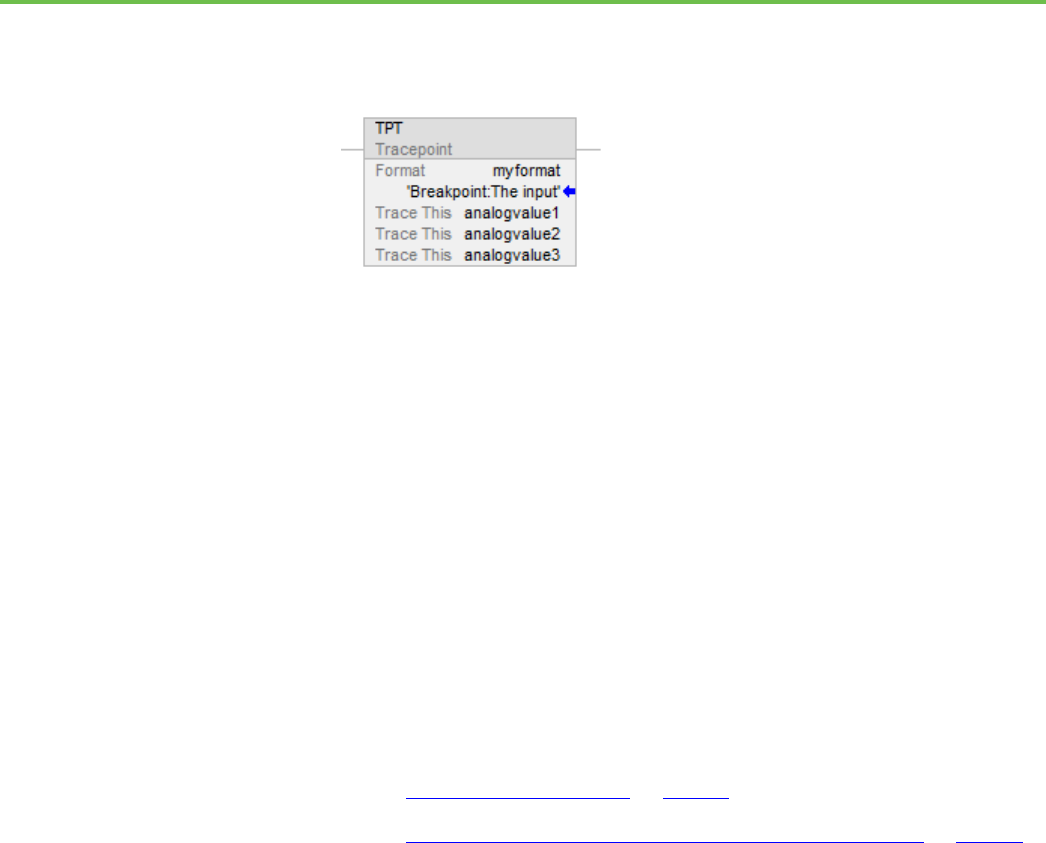
Chapter 9 Breakpoint and tracepoint instructions
54 Rockwell Automation Publication LGEM5K-GR016M-EN-E - November 2022
This is an example TPT instruction in a rung that triggers a trace with three
analog values when any one of the traces exceeds a given value. In this
example, the value indicated in the GRT instructions is 30.01.
• The Tracepoint (TPT) instrution
• The Format parameter. The value in this parameter specifies the
format of the breakpoint information to be displayed. In this example,
the format is myformat.
• The full string of the format is: Analog inputs trace:Analog inputs =
%f, %f, and %f
• The characters before the colon (Analog inputs trace) appear in
the title bar of the trace window. The %f characters that appear
after the colon represent the tags to be traced.
• The Trace This parameter. The value in this parameter is the tag to be
traced. In this example, there are three tags to be traced: analogvalue1,
analogvalue2, and analogvalue3.
See also
Tracepoint trace window on page 55
String formats for tracepoint and breakpoint instructions on page 55
To program the TPT instruction, set the format of trace reports as well as the
tag to trace.
To program a TPT instruction
• In the TPT instruction, change these two parameters:
• Format. Enter a string to set the formatting for both on-screen
reports and reports that are logged to disk. A string tag is required.
For example:
Analog inputs trace:
• Trace This. Enter the tag to trace. The tag must be an INT, BOOL,
SINT, DINT, or REAL tag. For example:
analogvalue1
Example TPT instruction
Program a TPT instruction

Chapter 9 Breakpoint and tracepoint instructions
Rockwell Automation Publication LGEM5K-GR016M-EN-E - November 2022 55
Tips:
• Tracing tag structures is not supported. For example, you cannot trace
entire timers or counters. Trace individual structure members.
• Tracing a large number of tags with the TPT instruction is supported.
The formatting string can contain only 82 characters. Two characters
must exist in the formatting string for each tag to trace. The maximum
number of tags to trace with a single TPT instruction is 41. Including
spaces and other formatting to separate tag data in traces significantly
reduces the resulting number of tags that the TPT instruction can trace
effectively.
See also
String formats for tracepoint and breakpoint instructions on page 55
Example TPT instruction on page 54
These are the items of a trace window for the example TPT instruction:
• The title bar includes the Slot number that contains the Studio 5000
Logix Emulate controller that has the tracepoint that is being traced in
this window. The title bar contains the portion of the value in the
Format parameter that appears before the colon. In this example, the
full string of the Format parameter is Analog inputs trace:Analog
inputs = %f, %f, and %f so Analog inputs appears in the title bar.
• The tags specified in the Trace This parameter of the TPT instruction.
• Freeze Display stops the trace window from updating so values from a
rapidly updating trace are readable.
• Clear Display Clears traces from the trace window.
• Freeze Log stops and starts logging when a trace is logging to disk.
This button is unavailable when a trace is not logging to disk.
See also
Program a TPT instruction on page 54
String formats for a tracepoint or breakpoint instruction on page 55
The Format string in the tracepoint and breakpoint instructions determines
how traced tags appear in a trace or breakpoint window. The format of the
string as:
heading:(text)%(type)
In the string, heading is a text string identifying the tracepoint or breakpoint,
text is a string describing the tag, or any other specified text, and %(type)
indicates the format of the tag. One type indicator is required for each tag
being traced with the tracepoint or breakpoint instruction.
For example, format a tracepoint string as:
Tracepoint trace window
String formats for a
tracepoint or breakpoint
instruction

Chapter 9 Breakpoint and tracepoint instructions
56 Rockwell Automation Publication LGEM5K-GR016M-EN-E - November 2022
My tracepoint:Tag 1 = %e and Tag 2 = %d
The %e formats the first traced tag as double-precision float with an exponent,
and %d formats the second traced tag as a signed decimal integer.
The value of any tag can be formatted with any flag. In this example, the
tracepoint instruction has two Trace This parameters -- one for a REAL and
one for an INT. The traces displayed in the resulting trace window might then
be as:
Tag 1 = 6.488484e+002 and Tag 2 = 443
Tag 1 = 6.617994e+002 and Tag 2 = 447
In these traces, the values for Tag 1 are REAL values (represented by %e in the
format string) and the values for Tag 2 are INT values (represented by %d in
the format string).
See also
Types for formatting tag values on page 56
Example TPT instruction on page 54
Example BPT instruction on page 52
Any type can be used for formatting any tag. The types are similar to those
used by the C++ print function. Available types for formatting tag values
include:
This type:
Formats the tag value as:
Example:
%d
Signed decimal integer. REAL values
are truncated.
45.3202 is rendered as 45.
%o
Unsigned octal integer. Non-octal
values are converted to octal. REAL
values are truncated.
45.3202 is rendered as 55.
%x
Unsigned hexadecimal integer with
letters rendered in lowercase.
Non-hex values are converted to
hex. REAL values are truncated.
45.3202 is rendered as 2d.
%X
Unsigned hexadecimal integer with
letters rendered in uppercase.
Non-hex values are converted to
hex. REAL values are truncated.
45.3202 is rendered as 2D.
%e
Signed floating point value with
exponent. The exponent delimiter
(e) is rendered in lowercase.
45.320200 is rendered as 4.532020e+001.
%E
Signed floating point value with
exponent. The exponent delimiter
(E) is rendered in uppercase.
45.320200 is rendered as 4.532020E+001.
%f
Signed floating point value without
exponent.
45.320200 is rendered as 45.320200.
Types for formatting tag
values
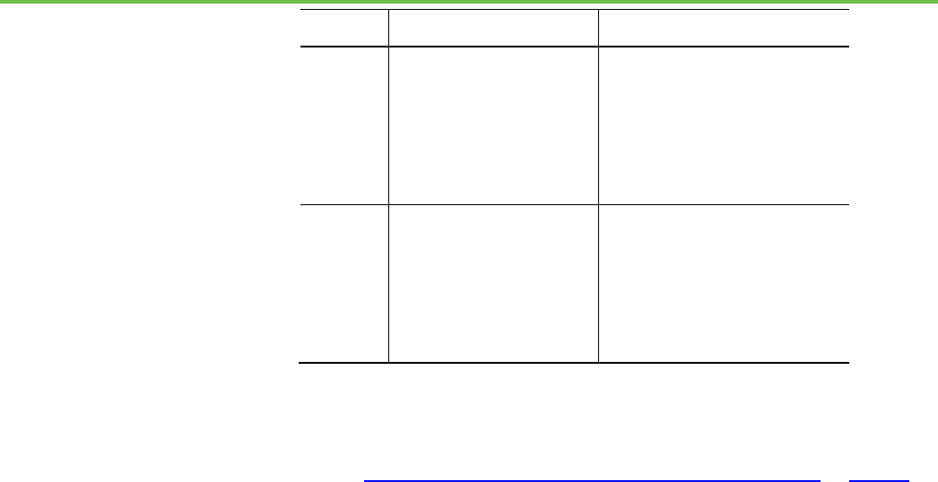
Chapter 9 Breakpoint and tracepoint instructions
Rockwell Automation Publication LGEM5K-GR016M-EN-E - November 2022 57
This type:
Formats the tag value as:
Example:
%g
Signed floating point value in %e or
%f format, whichever results in a
more compact display. Trailing
zeros are truncated, and the
decimal point appears only if one or
more digits follow it. The exponent
delimiter (e) is rendered in
lowercase (when it is appropriate).
45.320200 is rendered as 45.3202.
433222556.34322 is rendered as
4.3323e+008.
%G
Signed floating point value in %e or
%f format, whichever results in a
more compact display. Trailing
zeros are truncated, and the
decimal point appears only if one or
more digits follow it. The exponent
delimiter (E) is rendered in
uppercase (when it is appropriate).
45.320200 is rendered as 45.3202.
433222556.34322 is rendered as
4.3323E+008.
See also
String formats for a tracepoint or breakpoint instruction on page 55

Rockwell Automation Publication LGEM5K-GR016M-EN-E - November 2022 59
Chapter 10
I/O simulation
There are two methods for simulating I/O with Studio 5000 Logix Emulate.
Both methods can be used simultaneously:
• Create a simulated I/O module that simulates discrete I/O.
• Create another Studio 5000 Logix Emulate controller that produces
and consumes tags of any type.
Other applications, such as FactoryTalk View SE and FactoryTalk View ME,
can simulate I/O. FactoryTalk View ME and FactoryTalk View SE are HMI
design and runtime environments.
See also
Configure a produced tag on page 59
Make the producer an I/O module of the consumer on page 60
Create a consumed tag on page 61
A produced tag must be less than 500 bytes and must be a DINT, REAL, array
of DINTs or REALS, or user-defined data type.
Before you begin
• Take the Studio 5000 Logix Emulate controller offline.
To configure a produced tag
1. Open the Studio 5000 Logix Designer project for the Studio 5000 Logix
Emulate controller.
2. Open the Controller Tags folder. Produced tags must be scoped to the
controller.
3. Right-click the tag that the Studio 5000 Logix Emulate controller is to
produce, and then click Edit Tag Properties. The Tag Properties dialog
box opens.
4. In the Tag Properties window, select the Produce tag type.
5. Click Connection. The Produced Tag Connection dialog box opens.
Simulate I/O
Configure a produced tag

Chapter 10 I/O simulation
60 Rockwell Automation Publication LGEM5K-GR016M-EN-E - November 2022
6. In the Max Consumers box, select the number of consumers equal to
the number of emulated controllers that are to consume the tag, and
then click OK. The Produced Tag Connection dialog box closes.
7. Click OK. The Tag Properties dialog box closes.
See also
Create a consumed tag on page 61
Make the producer an I/O module of the consumer on page 60
Create a consumed tag on page 61
To configure a consumer tag, make the Studio 5000 Logix Emulate controller
that is producing the tag an I/O module of the emulated controller that is to
consume the tag.
Before you begin
• Take the Studio 5000 Logix Emulate controller offline.
To make the producer an I/O module of the consumer
1. Open the Studio 5000 Logix Designer project for the consuming
Studio 5000 Logix Emulate.
2. Right-click the I/O Configuration folder, and then click New Module.
The Select Module dialog box opens.
3. Open the Controllers folder, select Emulate 55x0 Controller, and then
click OK.
4. In the Select Major Revision dialog box, select the slot revision of the
producing Studio 5000 Logix Emulate controller and then click OK.
5. In the New Module dialog box, in the Name box, type the name of the
producing Studio 5000 Logix Emulate controller.
6. In the Slot box, select the slot number for the producing emulator and
then click OK.
7. Configure the producing Studio 5000 Logix Emulate controller in the
Module Properties dialog box as necessary and then click OK. The
producing Studio 5000 Logix Emulate is an I/O module of the
consuming emulated controller.
See also
Configure a produced tag on page 59
Create a consumed tag on page 61
Make the producer an I/O
module of the consumer

Chapter 10 I/O simulation
Rockwell Automation Publication LGEM5K-GR016M-EN-E - November 2022 61
Create a tag that consumes data from the producing Studio 5000 Logix
Emulate controller.
Before you begin
• Take the Studio 5000 Logix Emulate controller offline.
To create a consumed tag
1. In the Studio 5000 Logix Designer project for the consuming Studio
5000 Logix Emulate controller, create a tag that is scoped to the
controller or to a program.
2. Right-click the tag that the Studio 5000 Logix Emulate controller is to
consume, and then click Edit Tag Properties.
Tip:
A consumed tag must have the same data type and array size as the
produced tag that the consumed tag uses. If it does not, an I/O fault
occurs for the emulated controller that consumes the tag.
3. In the Tag Properties dialog box, select the Consumed tag type.
4. Click Connection. The Consumed Tag Connection dialog box opens.
5. From the Producer list, select the producing emulator.
6. In the Remote Data box, type the name of the tag that the producer is
producing.
7. In the RPI field, type the Requested Packet Interval (RPI) interval, in
milliseconds, that the consuming emulator pauses between data
requests for this tag. RPI is the minimum rate at which the emulator
consumes data.
8. Click OK.
9. In the Tag Properties dialog box, in the Data Type box, type the data
type for the consuming tag. The data type and the consuming tag must
be the same data type.
10. Click OK.
See also
Configure a produced tag on page 59
Make the producer an I/O module of the consumer on page 60
Create a consumed tag

Rockwell Automation Publication LGEM5K-GR016M-EN-E - November 2022 63
Chapter 11
Trace windows
A tracepoint or breakpoint window opens automatically when a tracepoint or
breakpoint instruction first executes. All current traces appear in the
Configure Emulation window. Use the Configure Emulation window to open
trace windows manually, specify the traces to show, and log traces.
Trace windows open automatically when a breakpoint or tracepoint executes.
If a trace window is no longer open, it is still available through the Configure
Emulation window. Open a trace window manually from the Configure
Emulation window.
To open a trace window
1. Right-click the Studio 5000 Logix Emulate controller and then select
Configure Emulation. The Configure Emulation window opens.
2. In the list of trace windows, double-click a trace to open the trace
window.
See also
Breakpoint trace window on page 53
Tracepoint trace window on page 55
Open trace windows automatically for all new tracepoints and breakpoints as
they execute. If a trace window is no longer open, the trace is still active. Open
the trace manually from the Configure Emulation window.
To open trace windows for new traces automatically
1. Right-click the Studio 5000 Logix Emulate controller and then select
Configure Emulation. The Configure Emulation window opens.
2. Select Display all new traces.
See also
Remove all traces on page 64
Log new traces to disk on page 64
Work with trace windows
Open a trace window
Open trace windows for
new traces automatically

Chapter 11 Trace windows
64 Rockwell Automation Publication LGEM5K-GR016M-EN-E - November 2022
Close all trace windows on page 64
Close all open trace windows simultaneously. If a trace window is not open, it
is still active. Reopen a trace window using the Configure Emulation window.
To close all trace windows
1. Right-click the emulated controller in the virtual chassis and then
select Configure Emulation. The Configure Emulation window
opens.
2. Click Close All Traces. All open trace windows close.
See also
Open a trace window on page 63
Remove all traces from the Configure Emulation window. This clears the list
of traces so that only new traces are listed when breakpoints or tracepoints
execute. When a trace is not listed in the Configure Emulation window,
manually opening the trace is not available.
To remove all traces
1. Right-click the emulated controller in the virtual chassis and then
select Configure Emulation. The Configure Emulation window
opens.
2. Click Remove All Traces. The list of traces on the right side of the
Configure Emulation window clears.
See also
Work with trace windows on page 63
Close all trace windows on page 64
To review traces from a file, log new traces to disk automatically. Traces are
logged to the file indicated on the Configure Emulation window. Open the
indicated log file to review the traces.
Close all trace windows
Remove all traces
Log new traces to disk

Chapter 11 Trace windows
Rockwell Automation Publication LGEM5K-GR016M-EN-E - November 2022 65
To log new traces to disk
1. Right-click the emulated controller in the virtual chassis and then
select Configure Emulation. The Configure Emulation window
opens.
2. Select the Log new traces to disk checkbox.
3. In the Trace Log File box, browse to select the text file to contain the
trace information. To create a new log file, in the File name box, type
the name of the new file.
Tip:
Log data to a file with any extension, including no extension. To be able to
view traces with a text editor, use a .txt extension.
4. Click Open. If the selected file contains data, a prompt appears to
append traces to the end of the file, or overwrite the data in the file
with the traces.
5. Execute the logic. When a TPT instruction executes, the trace
information logs to the selected file.
Tip:
To view the traces stored in the log file, from the Configure Emulation
window, click Close Log File. Open the log file in a text editor. Opening the
log file without closing it in the Configure Emulation window displays an
error message regarding not being able to access the file. Close the log
file before viewing it with another application.
See also
Open trace windows for new traces automatically on page 63
Log traces to a new log file on page 65
The Configure Emulation window displays the current file where traces are
logged. Change the file to log traces in a different file. To open the log file,
navigate to the indicated file on the computer.
To log traces to a new log file
1. Right-click the emulated controller in the virtual chassis and then
select Configure Emulation. The Configure Emulation window
opens.
2. After the Trace Log File box, click Browse, navigate to the file to log the
traces, and then click OK.
See also
Stop logging traces to a log file on page 66
Log new traces to disk on page 64
Log traces to a new log file

Chapter 11 Trace windows
66 Rockwell Automation Publication LGEM5K-GR016M-EN-E - November 2022
To review only the already logged traces, stop logging traces to a log file. The
log file to which traces are logged is listed in the Configure Emulation
window. Open this log file to review the breakpoints and tracepoints that
have executed.
To stop logging traces to a log file
1. Right-click the emulated controller in the virtual chassis and then
select Configure Emulation. The Configure Emulation window
opens.
2. Click Close Log File. Traces stop logging to the indicated log file.
See also
Log new traces to disk on page 64
Log traces to a new log file on page 65
Stop logging traces to a log
file

Rockwell Automation Publication LGEM5K-GR016M-EN-E - November 2022 67
Chapter 12
Snapshots of Studio 5000 Logix Emulate
controller states
Save a snapshot of the current state of emulated controllers in the virtual
chassis, or return controllers to a previous state through a saved snapshot.
See also
Save a snapshot of the state of multiple Studio 5000 Logix Emulate
controllers on page 67
Restore the state of multiple Studio 5000 Logix Emulate controllers on
page 68
When there are multiple emulated controllers within a single virtual chassis,
creating a snapshot saves the current state, including program and data
information, for one or more controllers.
To save a snapshot of the state of multiple Studio 5000 Logix
Emulate controllers
1. Click All Modules > Save Snapshot. The Save Snapshot dialog box
opens.
Tip:
All slots that contain emulated controllers in the virtual chassis appear
selected.
2. Clear the slots containing controllers to not include in the snapshot.
Tip:
Any controllers that are configured with the Periodic Save feature enabled
are unavailable.
3. In the Directory box, type or browse to the directory path to save the
snapshot.
4. In the Root name for files box, type the filename to contain the
snapshot information using the format name_Slotx.acd.
Tips:
• The name is a specified filename followed by x representing the numeric
slot number. For example, Sim1_Slot 3.acd.
• The characters V?:*\"<>| are not supported.
5. Click OK. All controllers in the specified slots transition to Run mode.
Tip:
If any of the selected controllers are in Program mode, a prompt appears.
Set the speed of time to 0% prior to the save. After the save operation is
complete, the controller returns to Run mode.
Work with snapshots of
Studio 5000 Logix Emulate
controller states
Save a snapshot of the
state of multiple Studio
5000 Logix Emulate
controllers

Chapter 12 Snapshots of Studio 5000 Logix Emulate controller states
68 Rockwell Automation Publication LGEM5K-GR016M-EN-E - November 2022
See also
Restore the state of multiple Studio 5000 Logix Emulate controllers on
page 68
If there is a previously saved snapshot of the state of multiple Studio 5000
Logix Emulate controllers in the virtual chassis, returning those controllers to
that previously saved state is supported.
To restore the state of multiple Studio 5000 Logix Emulate
controllers
1. Click All Modules > Restore. The Restore from Snapshot dialog box
opens.
Tip:
Slots, represented by all of the files in the Available File Groups box, appear
selected. If a file for a particular slot exists, but that slot no longer contains a
controller, the selection is unavailable.
2. In the Directory box, browse to or type the directory path where the
snapshot files are saved.
3. In the Available File Groups box, select a single snapshot file.
Tip:
The slots represented by the selected snapshot file appear selected.
4. Clear the slots that contain controllers to not restore toa previous state.
5. Click OK. All controllers in the specified slots transition to Run mode.
Studio 5000 Logix Emulate shuts down and then restarts. All of the
selected files are automatically loaded into the appropriate controllers
in the virtual chassis.
See also
Save the current state of multiple Studio 5000 Logix Emulate
controllers on page 67
Restore the state of
multiple Studio 5000 Logix
Emulate controllers

Index
Rockwell Automation Publication LGEM5K-GR016M-EN-E - November 2022 69
Index
1
1756-Module 26, 57
1789-SIM module 57
B
BPT 49
breakpoint instruction 49
example 50
program 50
string format 53
trace window 51
C
channel 0 serial port 23
communication
driver 37
emulated controller vs. Logix5000
controller 15
FactoryTalk View ME or FactoryTalk View
SE 41
with remote computer 39
configuration size 27
configure
emulator 23
trace display 49
consumed tags 58
continuous task dwell time 23
cpu affinity 23
current state 65
F
FactoryTalk Batch
remote communication to 39
FactoryTalk Directory
FactoryTalk ViewME or FactoryTalk
ViewSE 41
FactoryTalk ViewME
connect Studio 5000 Logix Emulate 41
tag browser 43
FactoryTalk ViewSE
browse 43
connect emulator 41
floating point 17
freeze display 51, 53
freeze log 51, 53
I
I/O
configuration assembly instance 27
input assembly instance 27
input size 27
output assembly instance 27
output size 27
simulate 26, 57
J
JSR instruction 15
JXR instruction 15
L
legal notice 7
license agreement 7
limitation 15
log
freeze 51, 53
log to disk 62
stop 63
unfreeze 51, 53
M
memory size 23
mode
program 31
run 32
single scan 33
using 31, 32
module
1756-MODULE 27, 57
1789-SIM 27, 57
RSLinx Enterprise 42
Studio 5000 Logix Emulate controller
23
multiple controller
current state 65
mode 31, 32
previous state 66
N
node 46
configure 46
O
OPC 45
topic 45
Operator Training 15
OTS 15

Index
70 Rockwell Automation Publication LGEM5K-GR016M-EN-E - November 2022
P
previous state 66
produced tag 57
program mode 31, 32
project 17
R
RSLinx Classic
communication driver 37
RSLinx Classic Gateway 39
RSLinx Classic Gateway 39
RSLinx Enterprise 45
module 19
server 42
run mode 32
S
simulated I/O
configure 27
create 57
single scan mode 33
slot 19
hide 20
speed of time 25
Studio 5000 Logix Designer
communcation with Studio 5000 Logix
Emulate 39
connection with Studio 5000 Logix
Emulate 37
project to use Studio 5000 Logix
Emulate 38
remote communications to 39
Studio 5000 Logix Designer controller
vs. emulated controller 15
T
tag
browse 43
configure 43
consumed 58
technical support 18
time
dwell 23
speed of 25
timeslice 23
timestamp 61, 62
TPT 51, 52
trace
log to disk 62, 63
log to log file 63
remove 62
trace log file 62, 63
trace window 51, 53
open 49, 51
tracepoint instruction 52
example 51
program 52, 53
string format 53
U
uninstall 12
update rate 20
V
virtual chassis 19
clear configuration 28
computer name 20
configure 23
keep on top 21
start 19
W
web site 18
technical support 18

Allen-Bradley, expanding human possibility, Logix, Rockwell Automation, and Rockwell Software are trademarks of Rockwell Automation, Inc.
EtherNet/IP is a trademark of ODVA, Inc.
Trademarks not belonging to Rockwell Automation are property of their respective companies.
Rockwell Otomayson Ticaret A.Ş. Kar Plaza İş Merkezi E Blok Kat:6 34752, İçerenkÖy, İstanbul, Tel: +90 (216) 5698400 EEE YÖnetmeliğine Uygundur
Rockwell Automation Publication LGEM5K-GR016M-EN-E - November 2022
Supersedes Publication LGEM5K-GR016L-EN-E Copyright © 2022 Rockwell Automation Technologies, Inc. All Rights Reserved. Printed in the U.S.A.
Rockwell Automation support
Use these resources to access support information.
Technical Support Center
Find help with how-to videos, FAQs, chat, user forums, and product notification
updates.
rok.auto/support
Knowledgebase
Access Knowledgebase articles.
rok.auto/knowledgebase
Local Technical Support Phone Numbers
Locate the telephone number for your country.
rok.auto/phonesupport
Literature Library
Find installation instructions, manuals, brochures, and technical data publications.
rok.auto/literature
Product Compatibility and Download Center
(PCDC)
Get help determining how products interact, check features and capabilities, and
find associated firmware.
rok.auto/pcdc
Documentation feedback
Your comments help us serve your documentation needs better. If you have any suggestions on how to improve our content, complete the form at
rok.auto/docfeedback.
Waste Electrical and Electronic Equipment (WEEE)
At the end of life, this equipment should be collected separately from any unsorted municipal waste.
Rockwell Automation maintains current product environmental information on its website at rok.auto/pec.
