Digital Scanner
Product Reference Guide
DS2278
MN-002915-13EN
ds2278-prg-en.book Page 1

ds2278-prg-en.book Page 2

DS2278 DIGITAL SCANNER
PRODUCT REFERENCE GUIDE
MN-002915-13EN
Revision A
January 2023
ds2278-prg-en.book Page i

ii DS2278 Digital Scanner Product Reference Guide
No part of this publication may be reproduced or used in any form, or by any electrical or mechanical means,
without permission in writing from Zebra. This includes electronic or mechanical means, such as photocopying,
recording, or information storage and retrieval systems. The material in this manual is subject to change
without notice.
The software is provided strictly on an “as is” basis. All software, including firmware, furnished to the user is on
a licensed basis. Zebra grants to the user a non-transferable and non-exclusive license to use each software
or firmware program delivered hereunder (licensed program). Except as noted below, such license may not be
assigned, sub-licensed, or otherwise transferred by the user without prior written consent of Zebra. No right to
copy a licensed program in whole or in part is granted, except as permitted under copyright law. The user shall
not modify, merge, or incorporate any form or portion of a licensed program with other program material, create
a derivative work from a licensed program, or use a licensed program in a network without written permission
from Zebra. The user agrees to maintain Zebra’s copyright notice on the licensed programs delivered
hereunder, and to include the same on any authorized copies it makes, in whole or in part. The user agrees not
to decompile, disassemble, decode, or reverse engineer any licensed program delivered to the user or any
portion thereof.
Zebra reserves the right to make changes to any software or product to improve reliability, function, or design.
Zebra does not assume any product liability arising out of, or in connection with, the application or use of any
product, circuit, or application described herein.
No license is granted, either expressly or by implication, estoppel, or otherwise under any Zebra Technologies
Corporation, intellectual property rights. An implied license only exists for equipment, circuits, and subsystems
contained in Zebra products.
Warranty
For the complete Zebra hardware product warranty statement, go to: www.zebra.com/warranty.
Patents
ip.zebra.com
ds2278-prg-en.book Page ii

iii
Revision History
Changes to the original guide are listed below:
Change Date Description
MN-002915-01 Rev. A 7/2017 Initial Release.
MN-002915-02 Rev. A 8/2017 Removed "Microsoft UWP Bluetooth" information.
MN-002915-03 Rev. A 04/2018 Rev. B software and miscellaneous updates.
Added:
- Battery Preservation Timeout Value.
- Re-pair on Double Trigger Press.
- Note to Out of Range Batch Mode about Auto-Reconnect.
- Added note below Bluetooth Security.
Updated:
- Pairing bar code format with STC info.
- Values under bar codes for SSI baud rates: 230,400, 460,800,
921,600.
- Pairing Using the Scan-To-Connect (STC) Utility.
- Max time value in Hands-Free Decode Session Timeout.
- Deleted Bluetooth HID - Wait for Connection (not supported).
- Added note to MSI Reduced Quiet Zone (Level 3 not supported by
MSI).
- Changed Microsoft UWP USB to USB HID POS.
- Second paragraph under "Connection Maintenance Interval".
- 123Scan chapter
- Picklist Mode description.
- Trigger Mode, Presentation (Blink) description.
MN-002915-04 Rev. A 7/2018 Added:
- LED on Good Decode.
- Pairing Bar Code Format for Serial Port Connections.
- USB certification.
- Setting Up a Windows Product To Work With The Digital Scanner.
- New Appendix N - U
pgrading Over Bluetooth Without a Cradle.
Updated:
- One instance of Class 1 to Class 2.
- Firmware download option (not supported with Micro USB cable).
- Configurations.
- "Connecting the Cradle" and "Changing the Host Interface".
MN-002915-05 Rev. A 10/2018 - Added Grid Matrix sample bar code.
- Moved 123Scan chapter.
MN-002915-06 Rev. A 01/2020 - Added ARINC param.
- Updated URLs.
- Updated Zebra copyright statement.
MN-002915-07EN Rev. A 04/2020 - Split 123Scan chapter to Chapter 2 123Scan and Software Tools and
Chapter 14 Data Formatting: ADF.
- Updated Chapter 2 123Scan Requirements.
- Updated Chapter 3 introduction section.
- Updated Environmental Sealing in Table 4-2.
- Added the USB Cert information in Table 4-2.
MN-002915-08EN Rev. A 12/2020
Replaced offending terms.
ds2278-prg-en.book Page iii

iv DS2278 Digital Scanner Product Reference Guide
MN-002915-09EN Rev. A 02/2021
Updated LED on Good Decode.
MN-002915-10EN Rev. A 04/2021
Removed Bluetooth Classic Bluetooth and/or Low Energy (Cradle
Parameter Only/ Cradle Host Only).
MN-002915-11EN Rev. A 07/2021
Added Standard Bluetooth Version 4.0 with BLE.
MN-002915-12EN Rev. A 09/2021
Added DotCode, DotCode Inverse, DotCode Mirrored, DotCode
Prioritize, DotCode Erasure Limit, Codabar Mod 16 Check Digit,
Transmit Codabar Check Digit, Transmit Ean-8 Check Digit, Transmit
Ean-13 Check Digit, Weblink QR, and Linked QR Mode.
MN-002915-13EN Rev. A
01/2023
Add Virtual Tether parameters. Update Bluetooth State Note.
Change Date Description
ds2278-prg-en.book Page iv

TABLE OF CONTENTS
Warranty ............................................................................................................................................ ii
Patents............................................................................................................................................... ii
Revision History ................................................................................................................................. iii
About This Guide
Introduction ...................................................................................................................................... xix
Configurations.................................................................................................................................. xix
Related Product Line Configurations ............................................................................................... xx
Cables........................................................................................................................................ xx
Chapter Descriptions ....................................................................................................................... xx
Notational Conventions.................................................................................................................... xxi
Related Documents ........................................................................................................................ xxii
Service Information ......................................................................................................................... xxii
Provide Documentation Feedback.................................................................................................. xxii
Chapter 1: Getting Started
Introduction .................................................................................................................................... 1-1
Interfaces ....................................................................................................................................... 1-2
Unpacking ...................................................................................................................................... 1-2
DS2278 Features ........................................................................................................................... 1-3
Cradle Features ............................................................................................................................. 1-3
Presentation Cradle ................................................................................................................. 1-4
Connecting the Cradle ............................................................................................................. 1-4
Changing the Host Interface .................................................................................................... 1-4
Using a DC Power Supply ........................................................................................................ 1-5
Charging the DS2278 Battery ........................................................................................................ 1-5
Charging Using the Cradle ....................................................................................................... 1-5
Charging Using the Micro USB Cable ...................................................................................... 1-6
Shutting Off the Digital Scanner Battery ........................................................................................ 1-7
Inserting the Battery ....................................................................................................................... 1-7
Removing the Battery .................................................................................................................... 1-8
Inserting the Digital Scanner in the Cradle .................................................................................... 1-9
Sending Data to the Host Computer .............................................................................................. 1-9
ds2278-prg-en.book Page v

vi DS2278 Digital Scanner Product Reference Guide
Pairing ...................................................................................................................................... 1-9
Lost Connection to Host ......................................................................................................... 1-10
Configuring the Digital Scanner ................................................................................................... 1-10
Radio Communications ................................................................................................................ 1-10
Accessories .................................................................................................................................. 1-10
Chapter 2: 123Scan and Software Tools
Introduction .................................................................................................................................... 2-1
123Scan ......................................................................................................................................... 2-1
Communication with 123Scan .................................................................................................. 2-2
123Scan Requirements ............................................................................................................ 2-2
123Scan Information ................................................................................................................ 2-2
Scanner SDK, Other Software Tools, and Videos ......................................................................... 2-3
Scanner Control App ...................................................................................................................... 2-4
Scan-To-Connect (STC) Utility ...................................................................................................... 2-4
Chapter 3: Data Capture
Introduction .................................................................................................................................... 3-1
Beeper and LED Indications .......................................................................................................... 3-1
Digital Scanner Indications ....................................................................................................... 3-1
Cradle LED Indications ............................................................................................................ 3-5
Scanning ........................................................................................................................................ 3-6
Hand-Held Scanning ................................................................................................................ 3-6
Hands-Free Scanning .............................................................................................................. 3-7
Aiming with Digital Scanner ..................................................................................................... 3-8
Aiming ...................................................................................................................................... 3-8
Decode Ranges ............................................................................................................................. 3-8
Chapter 4: Maintenance, Troubleshooting, & Technical Specifications
Introduction .................................................................................................................................... 4-1
Maintenance .................................................................................................................................. 4-1
Known Harmful Ingredients ...................................................................................................... 4-1
Approved Cleaners for the Digital Scanner and Cradle ........................................................... 4-2
Cleaning the Digital Scanner .................................................................................................... 4-2
Troubleshooting ............................................................................................................................. 4-3
Report Software Version Bar Code .......................................................................................... 4-7
Technical Specifications ................................................................................................................ 4-8
Cradle Signal Descriptions ........................................................................................................... 4-11
Chapter 5: User Preferences & Miscellaneous Options
Introduction .................................................................................................................................... 5-1
Setting Parameters ....................................................................................................................... 5-1
Scanning Sequence Examples ................................................................................................ 5-2
Errors While Scanning ............................................................................................................. 5-2
User Preferences/Miscellaneous Options Parameter Defaults ...................................................... 5-2
User Preferences ........................................................................................................................... 5-5
Default Parameters .................................................................................................................. 5-5
Parameter Bar Code Scanning ................................................................................................ 5-6
ds2278-prg-en.book Page vi

Table of Contents vii
Beep After Good Decode ......................................................................................................... 5-6
Beeper Volume ........................................................................................................................ 5-7
Beeper Tone ............................................................................................................................ 5-8
Beeper Duration ....................................................................................................................... 5-9
Suppress Power Up Beeps ...................................................................................................... 5-9
LED on Good Decode ............................................................................................................ 5-10
Direct Decode Indicator .......................................................................................................... 5-10
Low Power Mode ................................................................................................................... 5-11
Time Delay to Low Power Mode ............................................................................................ 5-12
Timeout to Low Power Mode from Auto Aim .......................................................................... 5-14
Battery Preservation Mode ..................................................................................................... 5-15
Trigger Mode .......................................................................................................................... 5-16
Hands-Free Mode .................................................................................................................. 5-17
Hand-Held Decode Aiming Pattern ........................................................................................ 5-18
Hands-Free (Presentation) Decode Aiming Pattern ............................................................... 5-19
Picklist Mode .......................................................................................................................... 5-20
Continuous Bar Code Read ................................................................................................... 5-21
Unique Bar Code Reporting ................................................................................................... 5-21
Decode Session Timeout ....................................................................................................... 5-22
Hands-Free Decode Session Timeout ................................................................................... 5-22
Timeout Between Decodes, Same Symbol ............................................................................ 5-23
Timeout Between Decodes, Different Symbols ...................................................................... 5-23
Decode Mirror Images (Data Matrix Only) ............................................................................. 5-24
Mobile Phone/Display Mode .................................................................................................. 5-24
PDF Prioritization ................................................................................................................... 5-25
PDF Prioritization Timeout ..................................................................................................... 5-25
Decoding Illumination ............................................................................................................. 5-26
Illumination Brightness ........................................................................................................... 5-26
Low Light Scene Detection .................................................................................................... 5-27
Motion Tolerance (Hand-Held Trigger Modes Only) .............................................................. 5-28
Product ID (PID) Type ............................................................................................................ 5-29
Product ID (PID) Value ........................................................................................................... 5-29
ECLevel .................................................................................................................................. 5-30
Miscellaneous Scanner Parameters ............................................................................................ 5-31
Enter Key ............................................................................................................................... 5-31
Tab Key .................................................................................................................................. 5-31
Transmit Code ID Character .................................................................................................. 5-32
Prefix/Suffix Values ................................................................................................................ 5-33
Scan Data Transmission Format ............................................................................................ 5-34
FN1 Substitution Values ......................................................................................................... 5-36
Transmit “No Read” Message ................................................................................................ 5-37
Unsolicited Heartbeat Interval ................................................................................................ 5-38
Send Versions .............................................................................................................................. 5-39
Software Version .................................................................................................................... 5-39
Serial Number ........................................................................................................................ 5-39
Manufacturing Information ..................................................................................................... 5-39
Chapter 6: Radio Communications
Introduction .................................................................................................................................... 6-1
Setting Parameters ....................................................................................................................... 6-1
ds2278-prg-en.book Page vii

viii DS2278 Digital Scanner Product Reference Guide
Scanning Sequence Examples ................................................................................................ 6-2
Errors While Scanning ............................................................................................................. 6-2
Radio Communications Parameter Defaults .................................................................................. 6-2
Wireless Beeper Definitions ........................................................................................................... 6-5
Radio Communication Host Types ................................................................................................ 6-5
Bluetooth Classic vs. Low Energy Bluetooth ............................................................................ 6-5
Cradle ....................................................................................................................................... 6-5
Human Interface Device (HID) Keyboard Emulation ................................................................ 6-6
Simple Serial Interface (SSI) .................................................................................................... 6-7
Serial Port Profile (SPP) ........................................................................................................... 6-9
Bluetooth Technology Profile Support ...................................................................................... 6-9
Central/Peripheral Set Up ...................................................................................................... 6-10
Bluetooth Friendly Name ............................................................................................................. 6-10
Discoverable Mode ................................................................................................................ 6-11
Wi-Fi Friendly Mode ..................................................................................................................... 6-12
Notes ...................................................................................................................................... 6-12
Wi-Fi Friendly Channel Exclusion .......................................................................................... 6-12
Radio Output Power ..................................................................................................................... 6-14
Link Supervision Timeout ....................................................................................................... 6-15
Bluetooth Radio State .................................................................................................................. 6-16
HID Host Parameters ................................................................................................................... 6-16
Apple iOS Virtual Keyboard Toggle ....................................................................................... 6-16
HID Keyboard Keystroke Delay ............................................................................................. 6-18
HID CAPS Lock Override ....................................................................................................... 6-18
HID Ignore Unknown Characters ........................................................................................... 6-19
Emulate Keypad ..................................................................................................................... 6-19
Fast HID Keyboard ................................................................................................................. 6-20
Quick Keypad Emulation ........................................................................................................ 6-20
HID Keyboard FN1 Substitution ............................................................................................. 6-21
HID Function Key Mapping .................................................................................................... 6-21
Simulated Caps Lock ............................................................................................................. 6-22
Convert Case ......................................................................................................................... 6-22
Auto-Reconnect Feature .............................................................................................................. 6-23
Reconnect Attempt Beep Feedback ...................................................................................... 6-23
Reconnect Attempt Interval .................................................................................................... 6-24
Auto-Reconnect ..................................................................................................................... 6-25
Out of Range Indicator ................................................................................................................. 6-25
Beep on Insertion ......................................................................................................................... 6-26
Beep on <BEL> ............................................................................................................................ 6-26
Digital Scanner To Cradle Support .............................................................................................. 6-27
Pairing .................................................................................................................................... 6-27
Pairing Methods ..................................................................................................................... 6-28
Connection Maintenance Interval ........................................................................................... 6-29
Pairing Using the Scan-To-Connect (STC) Utility ........................................................................ 6-31
Pairing Bar Code Format for Serial Port Connections ................................................................. 6-31
Pairing Bar Code Example ..................................................................................................... 6-31
Batch Mode .................................................................................................................................. 6-32
Modes of Operation ................................................................................................................ 6-32
Persistent Batch Storage ............................................................................................................. 6-34
Bluetooth Security ........................................................................................................................ 6-35
ds2278-prg-en.book Page viii

Table of Contents ix
PIN Code ................................................................................................................................ 6-35
Bluetooth Security Levels ....................................................................................................... 6-37
Bluetooth Radio, Linking, and Batch Operation ........................................................................... 6-38
Setting Up an iOS or Android Product To Work With The Digital Scanner ............................ 6-38
Setting Up a Windows Product To Work With The Digital Scanner ....................................... 6-39
Save Bluetooth Connection Information ...................................................................................... 6-40
Virtual Tether ............................................................................................................................... 6-41
Virtual Tether Alarm on the Scanner ...................................................................................... 6-41
Virtual Tether Alarm on the Cradle ......................................................................................... 6-44
Delay Before Virtual Alarm Activates ..................................................................................... 6-44
Virtual Tether Alarm Duration ................................................................................................. 6-45
Defeat Virtual Tether Alarm .................................................................................................... 6-46
Pause Virtual Tether Alarm Duration ..................................................................................... 6-46
Chapter 7: Signature Capture Preferences
Introduction .................................................................................................................................... 7-1
Setting Parameters ........................................................................................................................ 7-1
Scanning Sequence Examples ................................................................................................ 7-2
Errors While Scanning ............................................................................................................. 7-2
Signature Capture Preferences Parameter Defaults ..................................................................... 7-2
Signature Capture Preferences ..................................................................................................... 7-3
Signature Capture .................................................................................................................... 7-3
Signature Capture File Format Selector ................................................................................... 7-4
Signature Capture Bits Per Pixel .............................................................................................. 7-5
Signature Capture Width .......................................................................................................... 7-6
Signature Capture Height ......................................................................................................... 7-6
Signature Capture JPEG Quality ............................................................................................. 7-6
Chapter 8: USB Interface
Introduction .................................................................................................................................... 8-1
Setting Parameters ....................................................................................................................... 8-1
Scanning Sequence Examples ................................................................................................ 8-1
Errors While Scanning ............................................................................................................. 8-1
Connecting a USB Interface .......................................................................................................... 8-2
USB Parameter Defaults ................................................................................................................ 8-3
USB Host Parameters .................................................................................................................... 8-5
USB Device Type ..................................................................................................................... 8-5
Symbol Native API (SNAPI) Status Handshaking .................................................................... 8-7
Native Firmware Update .......................................................................................................... 8-7
USB Keystroke Delay ............................................................................................................... 8-8
USB CAPS Lock Override ........................................................................................................ 8-8
Bar Codes with Unknown Characters ...................................................................................... 8-9
USB Convert Unknown to Code 39 .......................................................................................... 8-9
USB Fast HID ......................................................................................................................... 8-10
USB Polling Interval ............................................................................................................... 8-11
Keypad Emulation .................................................................................................................. 8-13
Quick Keypad Emulation ........................................................................................................ 8-13
Keypad Emulation with Leading Zero .................................................................................... 8-14
USB Keyboard FN1 Substitution ............................................................................................ 8-14
ds2278-prg-en.book Page ix

x DS2278 Digital Scanner Product Reference Guide
Function Key Mapping ........................................................................................................... 8-15
Simulated Caps Lock ............................................................................................................. 8-15
Convert Case ......................................................................................................................... 8-16
USB Static CDC ..................................................................................................................... 8-16
CDC Beep on <BEL> ............................................................................................................. 8-17
USB CDC Host Variant .......................................................................................................... 8-17
TGCS (IBM) USB Direct I/O Beep ......................................................................................... 8-19
TGCS (IBM) USB Beep Directive ........................................................................................... 8-20
TGCS (IBM) USB Bar Code Configuration Directive ............................................................. 8-20
TGCS (IBM) USB Specification Version ................................................................................ 8-21
ASCII Character Sets for USB ..................................................................................................... 8-21
Chapter 9: SSI Interface
Introduction .................................................................................................................................... 9-1
Communication .............................................................................................................................. 9-1
SSI Transactions ............................................................................................................................ 9-3
General Data Transactions ...................................................................................................... 9-3
Decoded Data Transmission .................................................................................................... 9-4
Communication Summary .............................................................................................................. 9-6
RTS/CTS Lines ........................................................................................................................ 9-6
ACK/NAK Option ...................................................................................................................... 9-6
Number of Data Bits ................................................................................................................. 9-6
Serial Response Timeout ......................................................................................................... 9-6
Retries ...................................................................................................................................... 9-6
Baud Rate, Stop Bits, Parity, Response Timeout, ACK/NAK Handshaking ............................. 9-6
Errors ....................................................................................................................................... 9-6
SSI Communication Notes ....................................................................................................... 9-7
Using Time Delay to Low Power Mode with SSI ............................................................................ 9-7
Encapsulation of RSM Commands/Responses over SSI .............................................................. 9-8
Command Structure ................................................................................................................. 9-8
Response Structure ................................................................................................................. 9-8
Example Transaction ............................................................................................................... 9-9
Setting Parameters ..................................................................................................................... 9-10
Scanning Sequence Examples .............................................................................................. 9-10
Errors While Scanning ........................................................................................................... 9-10
Simple Serial Interface Parameter Defaults ................................................................................. 9-11
SSI Host Parameters ................................................................................................................... 9-12
Select SSI Host ...................................................................................................................... 9-12
Baud Rate .............................................................................................................................. 9-12
Parity ...................................................................................................................................... 9-14
Check Parity ........................................................................................................................... 9-15
Stop Bits ................................................................................................................................. 9-15
Software Handshaking ........................................................................................................... 9-16
Host RTS Line State .............................................................................................................. 9-17
Decode Data Packet Format .................................................................................................. 9-17
Host Serial Response Timeout .............................................................................................. 9-18
Host Character Timeout ......................................................................................................... 9-19
Multipacket Option ................................................................................................................. 9-20
Interpacket Delay ................................................................................................................... 9-21
Event Reporting ........................................................................................................................... 9-22
ds2278-prg-en.book Page x

Table of Contents xi
Decode Event ......................................................................................................................... 9-22
Boot Up Event ........................................................................................................................ 9-23
Parameter Event .................................................................................................................... 9-23
Chapter 10: RS-232 Interface
Introduction .................................................................................................................................. 10-1
Setting Parameters ..................................................................................................................... 10-1
Scanning Sequence Examples .............................................................................................. 10-2
Errors While Scanning ........................................................................................................... 10-2
Connecting an RS-232 Interface .................................................................................................. 10-2
RS-232 Parameter Defaults ......................................................................................................... 10-3
RS-232 Host Parameters ............................................................................................................. 10-4
RS-232 Host Types ................................................................................................................ 10-6
Baud Rate .............................................................................................................................. 10-8
Parity ...................................................................................................................................... 10-9
Stop Bits ................................................................................................................................. 10-9
Data Bits ............................................................................................................................... 10-10
Check Receive Errors .......................................................................................................... 10-10
Hardware Handshaking ........................................................................................................ 10-11
Software Handshaking ......................................................................................................... 10-13
Host Serial Response Timeout ............................................................................................ 10-15
RTS Line State ..................................................................................................................... 10-16
Beep on <BEL> .................................................................................................................... 10-16
Intercharacter Delay ............................................................................................................. 10-17
Nixdorf Beep/LED Options ................................................................................................... 10-18
Bar Codes with Unknown Characters .................................................................................. 10-18
ASCII Character Set for RS-232 ................................................................................................ 10-18
Chapter 11: IBM 468X / 469X Interface
Introduction .................................................................................................................................. 11-1
Setting Parameters ..................................................................................................................... 11-1
Scanning Sequence Examples .............................................................................................. 11-1
Errors While Scanning ........................................................................................................... 11-2
Connecting an IBM 468X/469X Host ........................................................................................... 11-2
IBM Parameter Defaults ............................................................................................................... 11-3
IBM Host Parameters ................................................................................................................... 11-4
Port Address .......................................................................................................................... 11-4
Convert Unknown to Code 39 ................................................................................................ 11-5
RS-485 Beep Directive ........................................................................................................... 11-5
RS-485 Bar Code Configuration Directive ............................................................................. 11-6
IBM-485 Specification Version ............................................................................................... 11-6
Chapter 12: Keyboard Wedge Interface
Introduction .................................................................................................................................. 12-1
Setting Parameters ..................................................................................................................... 12-1
Scanning Sequence Examples .............................................................................................. 12-1
Errors While Scanning ........................................................................................................... 12-1
Connecting a Keyboard Wedge Interface .................................................................................... 12-2
Keyboard Wedge Parameter Defaults ......................................................................................... 12-3
ds2278-prg-en.book Page xi

xii DS2278 Digital Scanner Product Reference Guide
Keyboard Wedge Host Parameters ............................................................................................. 12-4
Keyboard Wedge Host Types ................................................................................................ 12-4
Bar Codes with Unknown Characters .................................................................................... 12-4
Keystroke Delay ..................................................................................................................... 12-5
Intra-keystroke Delay ............................................................................................................. 12-5
Alternate Numeric Keypad Emulation .................................................................................... 12-6
Quick Keypad Emulation ........................................................................................................ 12-6
Simulated Caps Lock ............................................................................................................. 12-7
Caps Lock Override ............................................................................................................... 12-7
Convert Case ......................................................................................................................... 12-8
Function Key Mapping ........................................................................................................... 12-8
FN1 Substitution ..................................................................................................................... 12-9
Send Make and Break ............................................................................................................ 12-9
Keyboard Map ............................................................................................................................ 12-10
ASCII Character Set for Keyboard Wedge ................................................................................ 12-10
Chapter 13: Symbologies
Introduction .................................................................................................................................. 13-1
Setting Parameters ..................................................................................................................... 13-1
Scanning Sequence Examples .............................................................................................. 13-2
Errors While Scanning ........................................................................................................... 13-2
Symbology Parameter Defaults ................................................................................................... 13-2
Enable/Disable All Code Types ................................................................................................... 13-8
UPC/EAN/JAN ............................................................................................................................. 13-9
UPC-A .................................................................................................................................... 13-9
UPC-E .................................................................................................................................... 13-9
UPC-E1 ................................................................................................................................ 13-10
EAN-8/JAN-8 ........................................................................................................................ 13-10
EAN-13/JAN-13 .................................................................................................................... 13-11
Bookland EAN ...................................................................................................................... 13-11
Bookland ISBN Format ........................................................................................................ 13-12
ISSN EAN ............................................................................................................................ 13-12
Decode UPC/EAN/JAN Supplementals ............................................................................... 13-13
User-Programmable Supplementals .................................................................................... 13-16
UPC/EAN/JAN Supplemental Redundancy ......................................................................... 13-16
UPC/EAN/JAN Supplemental AIM ID Format ...................................................................... 13-17
Transmit UPC-A Check Digit ................................................................................................ 13-18
Transmit UPC-E Check Digit ................................................................................................ 13-18
Transmit UPC-E1 Check Digit .............................................................................................. 13-19
Transmit EAN-8 Check Digit ................................................................................................ 13-19
Transmit EAN-13 Check Digit .............................................................................................. 13-20
UPC-A Preamble .................................................................................................................. 13-21
UPC-E Preamble .................................................................................................................. 13-22
UPC-E1 Preamble ................................................................................................................ 13-23
Convert UPC-E to UPC-A .................................................................................................... 13-24
Convert UPC-E1 to UPC-A .................................................................................................. 13-24
EAN/JAN Zero Extend ......................................................................................................... 13-25
UCC Coupon Extended Code .............................................................................................. 13-25
Coupon Report ..................................................................................................................... 13-26
UPC Reduced Quiet Zone ................................................................................................... 13-26
ds2278-prg-en.book Page xii

Table of Contents xiii
Code 128 ................................................................................................................................... 13-27
Set Lengths for Code 128 .................................................................................................... 13-27
GS1-128 (formerly UCC/EAN-128) ...................................................................................... 13-28
ISBT 128 .............................................................................................................................. 13-29
ISBT Concatenation ............................................................................................................. 13-30
Check ISBT Table ................................................................................................................ 13-31
ISBT Concatenation Redundancy ........................................................................................ 13-31
Code 128 <FNC4> ............................................................................................................... 13-32
Code 128 Security Level ...................................................................................................... 13-32
Code 128 Reduced Quiet Zone ........................................................................................... 13-33
Code 39 ..................................................................................................................................... 13-34
Trioptic Code 39 ................................................................................................................... 13-34
Convert Code 39 to Code 32 ............................................................................................... 13-35
Code 32 Prefix ..................................................................................................................... 13-35
Set Lengths for Code 39 ...................................................................................................... 13-36
Code 39 Check Digit Verification ......................................................................................... 13-37
Transmit Code 39 Check Digit ............................................................................................. 13-38
Code 39 Full ASCII Conversion ........................................................................................... 13-38
Code 39 Security Level ........................................................................................................ 13-39
Code 39 Reduced Quiet Zone ............................................................................................. 13-41
Code 93 ..................................................................................................................................... 13-41
Set Lengths for Code 93 ...................................................................................................... 13-42
Code 11 ..................................................................................................................................... 13-44
Set Lengths for Code 11 ...................................................................................................... 13-44
Code 11 Check Digit Verification ......................................................................................... 13-46
Transmit Code 11 Check Digits ........................................................................................... 13-47
Interleaved 2 of 5 (ITF/I 2 of 5) .................................................................................................. 13-47
Set Lengths for Interleaved 2 of 5 ........................................................................................ 13-48
I 2 of 5 Check Digit Verification ............................................................................................ 13-50
Transmit I 2 of 5 Check Digit ................................................................................................ 13-51
Convert I 2 of 5 to EAN-13 ................................................................................................... 13-51
Febraban .............................................................................................................................. 13-52
I 2 of 5 Security Level ........................................................................................................... 13-53
I 2 of 5 Reduced Quiet Zone ................................................................................................ 13-54
Discrete 2 of 5 (DTF/D 2 of 5) .................................................................................................... 13-54
Set Lengths for Discrete 2 of 5 ............................................................................................. 13-55
Codabar (NW - 7) ....................................................................................................................... 13-57
Set Lengths for Codabar ...................................................................................................... 13-57
CLSI Editing ......................................................................................................................... 13-59
NOTIS Editing ...................................................................................................................... 13-59
Codabar Upper or Lower Case Start/Stop Characters ......................................................... 13-60
Codabar Mod 16 Check Digit Verification ............................................................................ 13-60
Transmit Codabar Check Digit ............................................................................................. 13-61
MSI ............................................................................................................................................. 13-61
Set Lengths for MSI ............................................................................................................. 13-62
MSI Check Digits .................................................................................................................. 13-64
Transmit MSI Check Digit(s) ................................................................................................ 13-64
MSI Check Digit Algorithm ................................................................................................... 13-65
MSI Reduced Quiet Zone ..................................................................................................... 13-65
Chinese 2 of 5 ............................................................................................................................ 13-66
ds2278-prg-en.book Page xiii

xiv DS2278 Digital Scanner Product Reference Guide
Matrix 2 of 5 ............................................................................................................................... 13-66
Set Lengths for Matrix 2 of 5 ................................................................................................ 13-67
Matrix 2 of 5 Check Digit ...................................................................................................... 13-68
Transmit Matrix 2 of 5 Check Digit ....................................................................................... 13-69
Korean 3 of 5 ............................................................................................................................. 13-69
Inverse 1D .................................................................................................................................. 13-70
GS1 DataBar .............................................................................................................................. 13-71
GS1 DataBar Omnidirectional (formerly GS1 DataBar-14), GS1 DataBar Truncated, GS1 DataBar
Stacked, GS1 DataBar Stacked Omnidirectional ............................................................................. 13-71
GS1 DataBar Limited ........................................................................................................... 13-71
GS1 DataBar Expanded, GS1 DataBar Expanded Stacked ................................................ 13-72
Convert GS1 DataBar to UPC/EAN/JAN ............................................................................. 13-72
GS1 DataBar Limited Margin Check .................................................................................... 13-73
GS1 DataBar Security Level ................................................................................................ 13-74
Symbology-Specific Security Features ...................................................................................... 13-75
Redundancy Level ............................................................................................................... 13-75
Security Level ....................................................................................................................... 13-77
1D Quiet Zone Level ............................................................................................................ 13-78
Intercharacter Gap Size ....................................................................................................... 13-79
Composite .................................................................................................................................. 13-79
Composite CC-C .................................................................................................................. 13-79
Composite CC-A/B ............................................................................................................... 13-80
Composite TLC-39 ............................................................................................................... 13-80
Composite Inverse ............................................................................................................... 13-81
UPC Composite Mode ......................................................................................................... 13-82
Composite Beep Mode ......................................................................................................... 13-83
GS1-128 Emulation Mode for UCC/EAN Composite Codes ................................................ 13-83
2D Symbologies ......................................................................................................................... 13-84
PDF417 ................................................................................................................................ 13-84
MicroPDF417 ....................................................................................................................... 13-84
Code 128 Emulation ............................................................................................................. 13-85
Data Matrix ........................................................................................................................... 13-86
GS1 Data Matrix ................................................................................................................... 13-86
Data Matrix Inverse .............................................................................................................. 13-87
Decode Data Matrix Mirror Images ...................................................................................... 13-88
Maxicode .............................................................................................................................. 13-89
QR Code .............................................................................................................................. 13-89
GS1 QR ............................................................................................................................... 13-90
MicroQR ............................................................................................................................... 13-90
Weblink QR .......................................................................................................................... 13-91
Linked QR ............................................................................................................................ 13-92
Aztec .................................................................................................................................... 13-93
Aztec Inverse ....................................................................................................................... 13-93
Han Xin ................................................................................................................................ 13-94
Han Xin Inverse .................................................................................................................... 13-94
Grid Matrix ............................................................................................................................ 13-95
Grid Matrix Inverse ............................................................................................................... 13-95
Grid Matrix Mirror ................................................................................................................. 13-96
DotCode ............................................................................................................................... 13-97
DotCode Inverse .................................................................................................................. 13-98
ds2278-prg-en.book Page xiv

Table of Contents xv
DotCode Mirrored ................................................................................................................. 13-99
DotCode Prioritize .............................................................................................................. 13-100
DotCode Erasure Limit ....................................................................................................... 13-100
Escape Characters ............................................................................................................. 13-101
Flush Macro PDF Buffer ..................................................................................................... 13-101
Abort Macro PDF Entry ...................................................................................................... 13-101
Postal Codes ............................................................................................................................ 13-102
US Postnet ......................................................................................................................... 13-102
US Planet ........................................................................................................................... 13-102
Transmit US Postal Check Digit ......................................................................................... 13-103
UK Postal ........................................................................................................................... 13-103
Transmit UK Postal Check Digit ......................................................................................... 13-104
Japan Postal ...................................................................................................................... 13-104
Australia Post ..................................................................................................................... 13-105
Australia Post Format ......................................................................................................... 13-106
Netherlands KIX Code ...................................................................................................... 13-107
USPS 4CB/One Code/Intelligent Mail ................................................................................ 13-107
UPU FICS Postal ............................................................................................................... 13-108
Mailmark ............................................................................................................................. 13-108
Chapter 14: Data Formatting: ADF
Introduction .................................................................................................................................. 14-1
Advanced Data Formatting (ADF) ................................................................................................ 14-1
Appendix A: Standard Default Parameters
Appendix B: Country Codes
Introduction ................................................................................................................................... B-1
USB and Keyboard Wedge Country Keyboard Types (Country Codes) ....................................... B-2
Appendix C: Country Code Pages
Introduction ................................................................................................................................... C-1
Country Code Page Defaults ........................................................................................................ C-1
Country Code Page Bar Codes .................................................................................................... C-5
Appendix D: CJK Decode Control
Introduction ................................................................................................................................... D-1
CJK Control Parameters ............................................................................................................... D-1
Unicode Output Control ........................................................................................................... D-1
CJK Output Method to Windows Host ..................................................................................... D-2
Non-CJK UTF Bar Code Output .............................................................................................. D-4
Unicode/CJK Decode Setup with Windows Host .......................................................................... D-5
Setting Up the Windows Registry Table for Unicode Universal Output .................................. D-5
Adding CJK IME on Windows ................................................................................................. D-5
Selecting the Simplified Chinese Input Method on the Host ................................................... D-6
Selecting the Traditional Chinese Input Method on the Host .................................................. D-7
ds2278-prg-en.book Page xv

xvi DS2278 Digital Scanner Product Reference Guide
Appendix E: Programming Reference
Symbol Code Identifiers ................................................................................................................ E-1
AIM Code Identifiers ..................................................................................................................... E-3
Appendix F: Sample Bar Codes
UPC/EAN ...................................................................................................................................... F-1
UPC-A, 100% ........................................................................................................................... F-1
UPC-A with 2-digit Add-on ....................................................................................................... F-1
UPC-A with 5-digit Add-on ....................................................................................................... F-2
UPC-E ...................................................................................................................................... F-2
UPC-E with 2-digit Add-on ....................................................................................................... F-2
UPC-E with 5-digit Add-on ....................................................................................................... F-3
EAN-8 ....................................................................................................................................... F-3
EAN-13, 100% ......................................................................................................................... F-3
EAN-13 with 2-digit Add-on ...................................................................................................... F-4
EAN-13 with 5-digit Add-on ...................................................................................................... F-4
Code 128 ....................................................................................................................................... F-5
GS1-128 ................................................................................................................................... F-5
Code 39 ......................................................................................................................................... F-5
Code 93 ......................................................................................................................................... F-6
Code 11 with 2 Check Digits .......................................................................................................... F-6
Interleaved 2 of 5 ........................................................................................................................... F-6
MSI with 2 Check Digits ................................................................................................................. F-7
Chinese 2 of 5 ................................................................................................................................ F-7
Matrix 2 of 5 ................................................................................................................................... F-7
Korean 3 of 5 ................................................................................................................................. F-8
GS1 DataBar .................................................................................................................................. F-8
GS1 DataBar Omnidirectional (formerly GS1 DataBar-14) ...................................................... F-8
GS1 DataBar Truncated ........................................................................................................... F-8
GS1 DataBar Stacked .............................................................................................................. F-9
GS1 DataBar Stacked Omnidirectional .................................................................................... F-9
GS1 DataBar Limited ............................................................................................................... F-9
GS1 DataBar Expanded ......................................................................................................... F-10
GS1 DataBar Expanded Stacked ........................................................................................... F-10
2D Symbologies ........................................................................................................................... F-11
PDF417 .................................................................................................................................. F-11
Data Matrix ............................................................................................................................. F-11
GS1 Data Matrix ..................................................................................................................... F-11
Maxicode ................................................................................................................................ F-12
QR Code ................................................................................................................................ F-12
GS1 QR .................................................................................................................................. F-12
MicroQR ................................................................................................................................. F-13
Aztec ...................................................................................................................................... F-13
Grid Matrix .............................................................................................................................. F-13
Han Xin .................................................................................................................................. F-14
Postal Codes ................................................................................................................................ F-14
US Postnet ............................................................................................................................. F-14
UK Postal ............................................................................................................................... F-14
Japan Post ............................................................................................................................. F-15
Australian Post ....................................................................................................................... F-15
ds2278-prg-en.book Page xvi

Table of Contents xvii
Appendix G: Numeric Bar Codes
Numeric Bar Codes ....................................................................................................................... G-1
Cancel ........................................................................................................................................... G-3
Appendix H: Alphaumeric Bar Codes
Cancel ........................................................................................................................................... H-1
Alphanumeric Bar Codes .............................................................................................................. H-2
Appendix I: ASCII Character Sets
Appendix J: Communication Protocol Functionality
Functionality Supported via Communication (Cable) Interface ...................................................... J-1
Appendix K: Signature Capture Code
Introduction ................................................................................................................................... K-1
Code Structure .............................................................................................................................. K-1
Signature Capture Area .......................................................................................................... K-1
CapCode Pattern Structure ..................................................................................................... K-2
Start / Stop Patterns ...................................................................................................................... K-2
Dimensions ................................................................................................................................... K-3
Data Format .................................................................................................................................. K-3
Additional Capabilities ................................................................................................................... K-4
Signature Boxes ............................................................................................................................ K-4
Appendix L: Non-Parameter Attributes
Introduction .................................................................................................................................... L-1
Attributes ........................................................................................................................................ L-1
Model Number .......................................................................................................................... L-1
Serial Number .......................................................................................................................... L-1
Date of Manufacture ................................................................................................................. L-2
Date of First Programming ....................................................................................................... L-2
Configuration Filename ............................................................................................................ L-2
Beeper/LED .............................................................................................................................. L-3
Parameter Defaults .................................................................................................................. L-4
Beep on Next Bootup ............................................................................................................... L-4
Reboot ...................................................................................................................................... L-4
Host Trigger Session ................................................................................................................ L-4
Firmware Version ..................................................................................................................... L-5
ImageKit Version ...................................................................................................................... L-5
In Cradle Detect ....................................................................................................................... L-5
Charging ................................................................................................................................... L-5
Battery Charge State ................................................................................................................ L-6
Appendix M: FIRMWARE UPGRADES USING iOS
Introduction ................................................................................................................................... M-1
Downloading Firmware Using the Zebra Scanner Control Application ......................................... M-1
ds2278-prg-en.book Page xvii

xviii DS2278 Digital Scanner Product Reference Guide
Appendix N: UPGRADING OVER BLUETOOTH WITHOUT A CRADLE
Introduction ................................................................................................................................... N-1
Upgrading Without a Cradle .......................................................................................................... N-1
Troubleshooting ............................................................................................................................ N-2
Index
ds2278-prg-en.book Page xviii

ABOUT THIS GUIDE
Introduction
The DS2278 Product Reference Guide provides general instructions for setting up, operating, maintaining, and
troubleshooting the DS2278 series digital scanner.
Configurations
This guide includes the DS2278 series digital scanner configurations listed in Table A.
Table A:
Digital Scanner and Cradle Configurations
Model Configuration Description
DS2278-SR00006ZZWW DS2278: Area Imager, Standard Range, Cordless, Nova White
DS2278-SR00007ZZWW DS2278: Area Imager, Standard Range, Cordless, Twilight Black
DS2278-SR00007ZZY DS2278: Area Imager, Standard Range, Cordless, Twilight Black - India only
CR2278-PC10004WW DS2278: Presentation Cradle, Bluetooth, Midnight Black
ds2278-prg-en.book Page xix

xx DS2278 Digital Scanner Product Reference Guide
Related Product Line Configurations
The product configurations related to the DS2278 digital scanner are as follows.
Cables
The full list of supported cables can be found at:
partnerportal.zebra.com/PartnerPortal/product_services/downloads_z/barcode_scanners/Universal-Cable-Guide-
Bar-Code-Scanners.xlsx.
Chapter Descriptions
Topics covered in this guide are as follows:
•
Chapter 1, Getting Started provides a product overview, unpacking instructions, and cable connection
information.
•
Chapter 2, 123Scan and Software Tools provides a brief description of the Zebra software tools available for
customizing digital scanner operation.
•
Chapter 3, Data Capture provides beeper and LED definitions, techniques involved in scanning bar codes,
general instructions and tips about scanning, and decode ranges.
•
Chapter 4, Maintenance, Troubleshooting, & Technical Specifications provides suggested digital scanner
maintenance, troubleshooting, technical specifications, and signal descriptions (pin outs).
•
Chapter 6, Radio Communications provides information about the modes of operation and features available
for wireless communication. This chapter also includes programming bar codes to configure the digital
scanner.
•
Chapter 5, User Preferences & Miscellaneous Options describes each user preference feature and provides
programming bar codes for selecting these features.
•
Chapter 8, USB Interface describes how to set up the digital scanner with a USB host.
•
Chapter 9, SSI Interface describes the system requirements of the Simple Serial Interface (SSI), which
provides a communications link between Zebra decoders and a serial host.
•
Chapter 10, RS-232 Interface describes how to set up the digital scanner with an RS-232 host.
•
Chapter 11, IBM 468X / 469X Interface describes how to set up the digital scanner with an IBM 468X/469X
host.
•
Chapter 12, Keyboard Wedge Interface describes how to set up a keyboard wedge interface with the digital
scanner.
NOTES Check Solution Builder for additional information regarding all available accessories, and the latest
available configurations.
Table B:
Accessories for the Digital Scanner
Product ID Description
BTRY-DS22EAB0E-00 Spare Battery, DS2278 Family
BTRY-DS22EAB0E-00Y Spare Battery, DS2278 Family, India only
25-MCXUSB-01R Micro USB Charge Only Cable
ds2278-prg-en.book Page xx

About This Guide xxi
•
Chapter 13, Symbologies describes all symbology features and provides programming bar codes for
selecting these features for the digital scanner.
•
Chapter 14, Data Formatting: ADF briefly describes the Zebra features available for customizing scanner
operation.
•
Appendix A, Standard Default Parameters provides a table of all host devices and miscellaneous digital
scanner defaults.
•
Appendix B, Country Codes provides bar codes for programming the country keyboard type for the USB
keyboard (HID) device and the keyboard wedge host.
•
Appendix C, Country Code Pages provides bar codes for selecting code pages for the country keyboard
type.
•
Appendix D, CJK Decode Control describes control parameters for Unicode/CJK (Chinese, Japanese,
Korean) bar code decode through USB HID Keyboard Emulation mode.
•
Appendix E, Programming Reference provides a table of AIM code identifiers, ASCII character conversions,
and keyboard maps.
•
Appendix F, Sample Bar Codes includes sample bar codes of various code types.
•
Appendix G, Numeric Bar Codes includes the numeric bar codes to scan for parameters requiring specific
numeric values.
•
Appendix H, Alphaumeric Bar Codes includes the alphanumeric bar codes to scan for parameters requiring
specific alphanumeric values.
•
Appendix I, ASCII Character Sets provides ASCII character value tables.
•
Appendix J, Communication Protocol Functionality lists supported digital scanner functionality by
communication protocol.
•
Appendix K, Signature Capture Code describes CapCode, a special pattern that encloses a signature area
on a document and allows the digital scanner to capture a signature.
•
Appendix L, Non-Parameter Attributes defines non-parameter attributes.
Notational Conventions
The following conventions are used in this document:
•
Unless stated otherwise, DS2278 refers to all configurations.
•
Italics are used to highlight the following:
• Chapters and sections in this and related documents
• Dialog box, window and screen names
• Drop-down list and list box names
• Check box and radio button names
•
Bold text is used to highlight the following:
• Key names on a keypad
• Button names on a screen.
ds2278-prg-en.book Page xxi

xxii DS2278 Digital Scanner Product Reference Guide
•
bullets (•) indicate:
• Action items
• Lists of alternatives
• Lists of required steps that are not necessarily sequential
•
Sequential lists (e.g., those that describe step-by-step procedures) appear as numbered lists.
•
Throughout the programming bar code menus, asterisks (*) are used to denote default parameter settings.
Related Documents
•
DS2278 Series Quick Start Guide, p/n MN-002916-xx - provides general information for getting started with
the DS2278 digital scanner, and includes basic set up and operation instructions.
•
Advanced Data Formatting Programmer Guide, p/n 72E-69680-xx - provides information on ADF, a means of
customizing data before transmission to a host.
•
Attribute Data Dictionary, p/n 72E-149786-xx defines attribute numbers (device configuration parameters,
monitored data, and born-on information) and describes management of various attribute domains for bar
code scanners and OEM engines.
For the latest version of this guide and all guides, go to: www.zebra.com/support
.
Service Information
If you have a problem using the equipment, contact your facility's technical or systems support. If there is a
problem with the equipment, they will contact the Zebra Support & Downloads website at: www.zebra.com/support.
When contacting support, please have the following information available:
•
Serial number of the unit
•
Model number or product name
•
Software type and version number
Zebra responds to calls by e-mail, telephone or fax within the time limits set forth in service agreements.
If your problem cannot be solved by support, you may need to return your equipment for servicing and will be given
specific directions. Zebra is not responsible for any damages incurred during shipment if the approved shipping
container is not used. Shipping the units improperly can possibly void the warranty.
If you purchased your business product from a Zebra business partner, please contact that business partner for
support.
Provide Documentation Feedback
If you have comments, questions, or suggestions about this guide, send an email to EVM-T[email protected].
*Baud Rate 9600
Feature/Option
* Indicates Default
ds2278-prg-en.book Page xxii

CHAPTER 1 GETTING STARTED
Introduction
2D bar codes have made their way to the Point of Sale (POS), appearing on everything from customer purchased
items to printed and electronic coupons and loyalty cards. 1D scanners cannot capture the new 2D codes, leading
to exceptions that slow down the check-out process. The DS2278 digital imager scanner scans both 1D and 2D
bar codes and does not compromise performance or features.
The DS2278 is easy to deploy, easy to use, and easy to manage - delivering affordable simplicity with its
hands-free/hand-held design.
Figure 1-1 DS2278 Digital Scanner
ds2278-prg-en.book Page 1

1 - 2 DS2278 Digital Scanner Product Reference Guide
Interfaces
The DS2278 digital scanner cradle supports:
• USB connection to a host. The digital scanner automatically detects the USB host interface type and uses
the default setting (USB Keyboard HID). If the default (*) does not meet your requirements, select another
USB interface type by scanning programming bar code menus. See Appendix B, Country Codes for the
interface supported international keyboards (for Windows® environment).
• Standard RS-232 connection to a host. The digital scanner automatically detects the RS-232 host interface
type and uses the default setting (Standard RS-232). If the default (*) does not meet your requirements,
select another RS-232 interface type by scanning programming bar code menus.
• Connection to IBM 468X/469X hosts. The digital scanner automatically detects the IBM host interface type
but does not select a default setting. Scan bar code menus to set up communication of the digital scanner
with the IBM terminal.
• Keyboard Wedge connection to a host. The host interprets scanned data as keystrokes. The digital scanner
automatically detects the Keyboard Wedge host interface type and uses the default setting (IBM AT
Notebook). If the default (*) does not meet your requirements, scan IBM PC/AT & IBM PC Compatibles on
page 12-4. See Appendix B, Country Codes for the interface supported international keyboards (for
Windows® environment).
• Configuration via 123Scan.
Unpacking
Remove the digital scanner from its packing and inspect it for damage. If the digital scanner was damaged in
transit, contact support. See page xxii for information. KEEP THE PACKING. It is the approved shipping container;
use this to return the equipment for servicing.
NOTE For a list of supported digital scanner functionality by communication protocol, see Appendix J,
Communication Protocol Functionality.
ds2278-prg-en.book Page 2
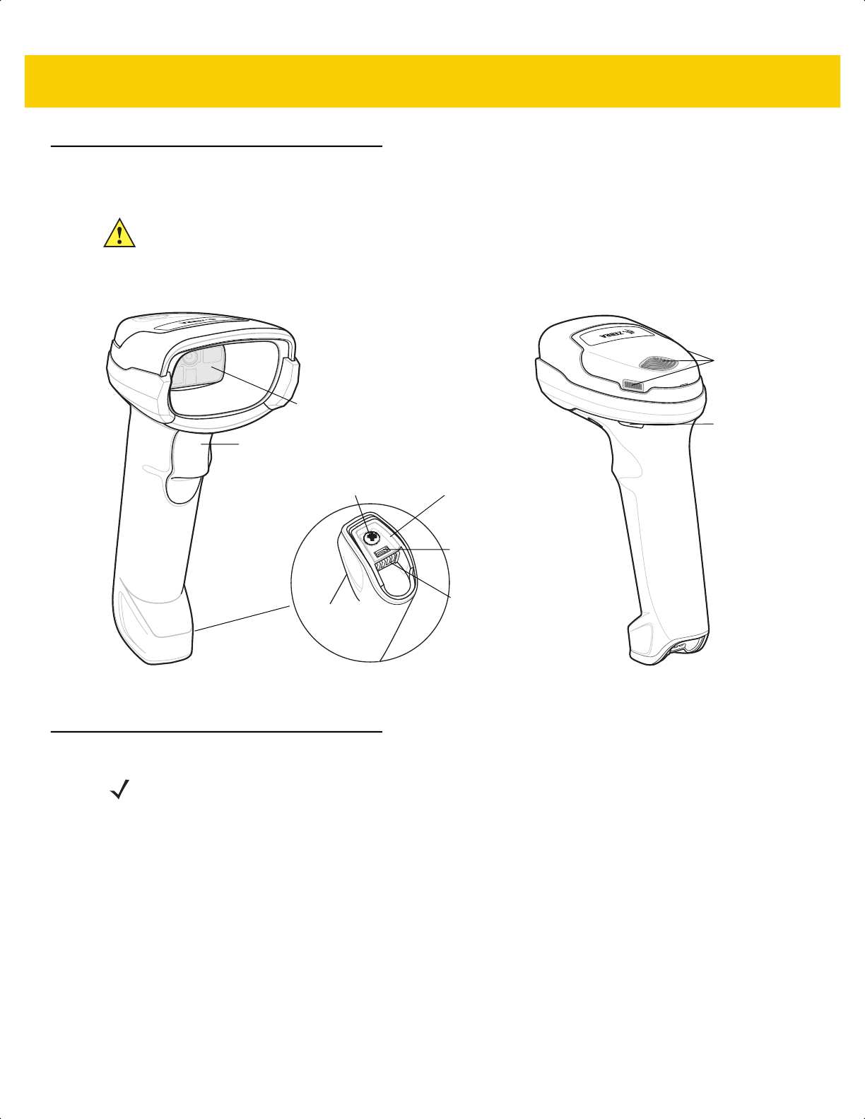
Getting Started 1 - 3
DS2278 Features
Figure 1-2 Digital Scanner Features
For detailed LED indicator information see Beeper and LED Indications on page 3-1.
Cradle Features
The CR2278-PC cordless presentation cradle serves as a charger, radio communication interface, and host
communication interface for the DS2278 cordless digital scanner.
The presentation cradle sits on a desktop and charges the DS2278 cordless digital scanner while allowing bar
code scanning in presentation mode. This cradle also provides host communication by receiving digital scanner
data via a Bluetooth radio, and sending that data to the host through an attached cable. The cable provides power
to the cradle from the host or optional power supply if supported.
For more information about communication between the digital scanner, cradle, and host, see Chapter 6, Radio
Communications.
IMPORTANT DO NOT use the CR2278-PC cradle with any scanners other than the DS2278 digital scanner.
No other cradles are compatible with the DS2278.
DO NOT use the DS2278 digital scanner with any cradles other than the CR2278-PC cradle. No
other scanners are compatible with the CR2278-PC cradle.
Beeper
Scan LEDs
Trigger
Scan Window
Battery
Compartment
Screw
Charging
Contacts
Battery
Compartment
Cover
Micro USB
Port
NOTE For detailed information about connecting, using, and mounting the CR2278-PC cradle refer to the
documentation included with the cradle (CR2278-PC Presentation Cradle Quick Reference
Guide, p/n MN-002917xx).
ds2278-prg-en.book Page 3
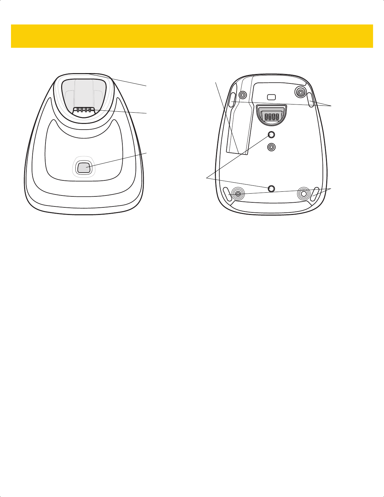
1 - 4 DS2278 Digital Scanner Product Reference Guide
Presentation Cradle
Figure 1-3 CR2278-PC (Presentation Cradle) -Top and Bottom Views
Connecting the Cradle
Via Host Connection (for Charging and Communication)
1. Connect the appropriate cable to the power supply and an AC power source, if necessary. This ensures
detection of the host and prevents inadvertently back powering the cradle from improper detection of the host.
2. Insert the interface cable into the host port.
3. Insert the interface cable into the cradle's host port.
4. Pair the digital scanner to the cradle either by inserting it in the cradle (if Pair on Contacts is enabled) or by
scanning the pairing bar code.
5. If necessary, scan the appropriate host bar code (for non-autodetected interfaces).
Via Wall Outlet Using a Power Adapter (for Charging Only)
1. Connect the appropriate cable to the power supply and an AC power source.
2. Insert the interface cable into the cradle's host port.
3. Pair the digital scanner directly to the host device (PC, Smartphone, or Tablet).
Changing the Host Interface
To connect to a different host, or to the same host through a different cable:
1. Unplug the interface cable from the host.
2. Unplug the power supply from the host cable, if required.
3. Connect the interface cable to the new host, or the new interface cable to the existing host.
4. Reconnect the power supply, if required.
5. If necessary, scan the appropriate host bar code (for non-autodetected interfaces).
Charging /
Communications
Contacts
Pairing Bar
Code (in back)
Rubber
Feet
Rubber
Feet
Interface Port
Station Mount
Threaded Brass
Screw Holes
(2 - M4 x 5 mm)
LED Indicator
ds2278-prg-en.book Page 4

Getting Started 1 - 5
Using a DC Power Supply
There is no separate power jack on the cradle. The cradle can operate from host supplied power, if available. If
host power is limited or not available, an external DC power supply can be used with certain host interface cables
that support a power jack. An external power supply is recommended if fastest charging is required. See host
interface chapters for connections.
Charging the DS2278 Battery
When using a new battery in the DS2278, the battery may require a charge to be enabled. See Charging the
DS2278 Battery on page 1-5.
Charging Using the Cradle
Insert the battery in the DS2278 and place the DS2278 in the CR2278-PC cradle (see Inserting the Digital Scanner
in the Cradle on page 1-9). The digital scanner boots and the cradle LED begins flashing green to indicate the start
of normal charging.
See Beeper and LED Indications on page 3-1 for detailed LED indicator information.
CAUTION Always disconnect the DC power supply BEFORE disconnecting the cable to the host end or the
cradle may not recognize the new host.
NOTES 1. It is recommended to fully charge the battery before first use.
2. Charge time depends on the host type and power source.
3. The CR2278-PC passes 5V to the digital scanner which charges the battery. The charging system on
the DS2278 charges the battery with as much current as possible based on the power source of the
CR2278-PC. This way the input power source is never overloaded and the charge time is made as
short as possible. Charge times lengthen as scanning activity increases when a DS2278 operates in
presentation mode on a CR2278-PC cradle. To optimize charge performance, ensure the digital
scanner is oriented to minimize accidental scan activation.
CAUTION The battery does not charge when the temperature is above 40°C (104°F). When scanning in
presentation mode at temperatures above 40°C (104°F), the battery drains until the temperature drops.
When the battery charge is consumed the digital scanner stops scanning until the temperature drops
and the battery has sufficient time to charge.
To avoid temperature related faults, charge the battery and operate the DS2278 in presentation mode
on a CR2278-PC only within the recommended 0°C to 40°C (32°F to 104°F) range, and ideally within
5°C to 35°C (41°F to 95°F).
ds2278-prg-en.book Page 5
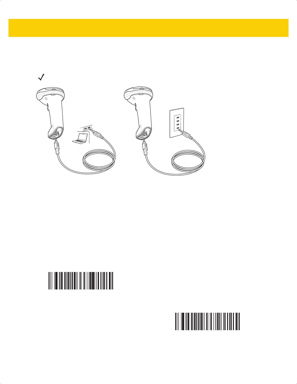
1 - 6 DS2278 Digital Scanner Product Reference Guide
Charging Using the Micro USB Cable
The Micro USB cable is a charge only cable.
Figure 1-4 Micro USB Connections
Connect the Micro USB connector to the DS2278. Connect the standard USB connector to a PC or a USB wall
outlet. The digital scanner enumerates as a CDC device when the USB connector is plugged into a PC host. When
charging begins, the digital scanner LED begins flashing green to indicate the start of normal charging.
Converting a CDC Device to HID
The digital scanner enumerates over USB as a CDC device, by default. If your host does not have a CDC driver, a
delay occurs between connecting the digital scanner to the host and the start of charging. To eliminate the delay
scan HID Device Conversion below to enumerate as an HID device. This allows the scanner to begin charging
sooner.
To switch the digital scanner back to a CDC device, scan Scanner as CDC Device below.
For instructions on downloading CDC drivers see page 8-6.
NOTE For best performance, we recommend using Zebra accessories.
HID Device Conversion
*Scanner as CDC Device
ds2278-prg-en.book Page 6
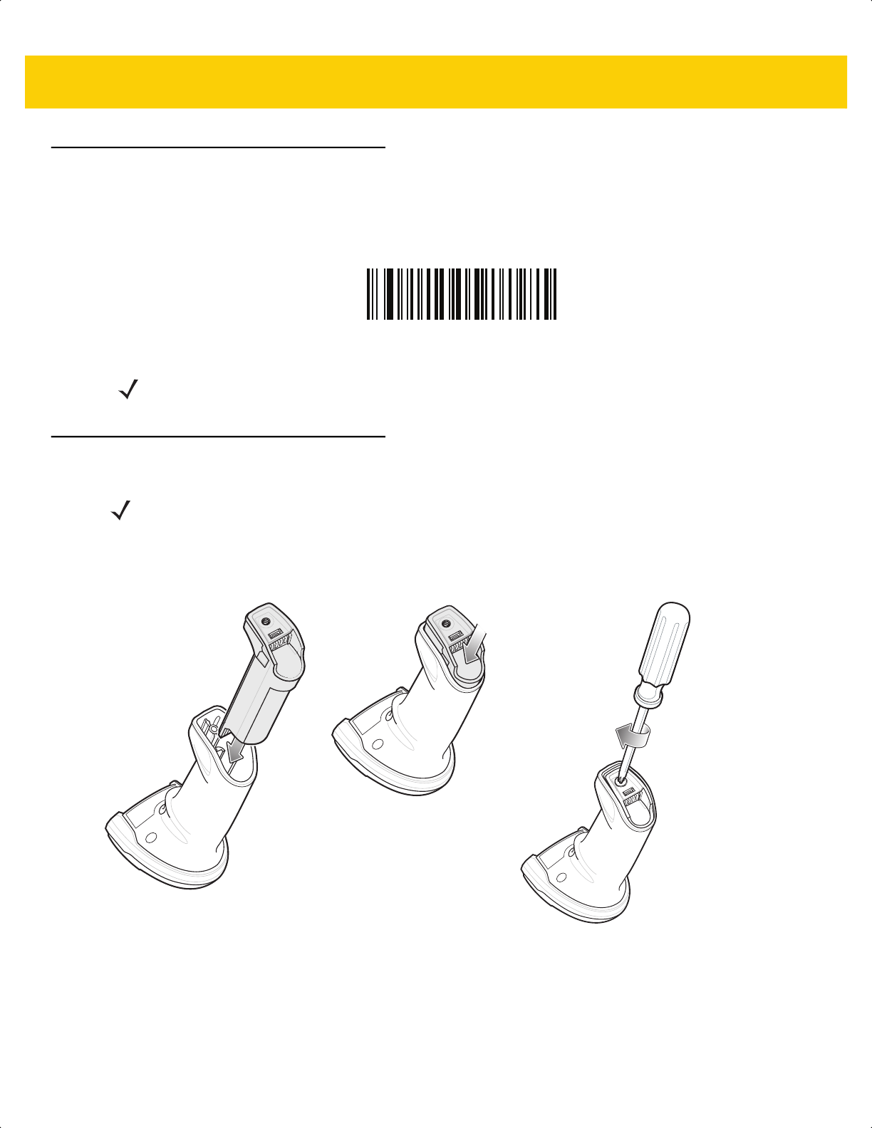
Getting Started 1 - 7
Shutting Off the Digital Scanner Battery
Scan the Battery Off bar code below to shut off the battery for long term storage or shipping. Pull the digital
scanner trigger to turn on the battery.
Battery Off
Inserting the Battery
Figure 1-5 Inserting the Battery
To insert the battery into the digital scanner:
1. Insert the battery into the battery compartment and push down.
2. Turn the screw on the battery compartment clockwise to tighten. Do not over torque the screw.
NOTE Always scan the Battery Off bar code in hand-held mode. Also see Battery Preservation Mode on page
5-15 for additional battery features.
NOTES
1.
It is recommended to fully charge the battery before first use.
2. The battery is initially shipped inside the digital scanner. Inserting a battery would only be
applicable for a replacement battery.
ds2278-prg-en.book Page 7
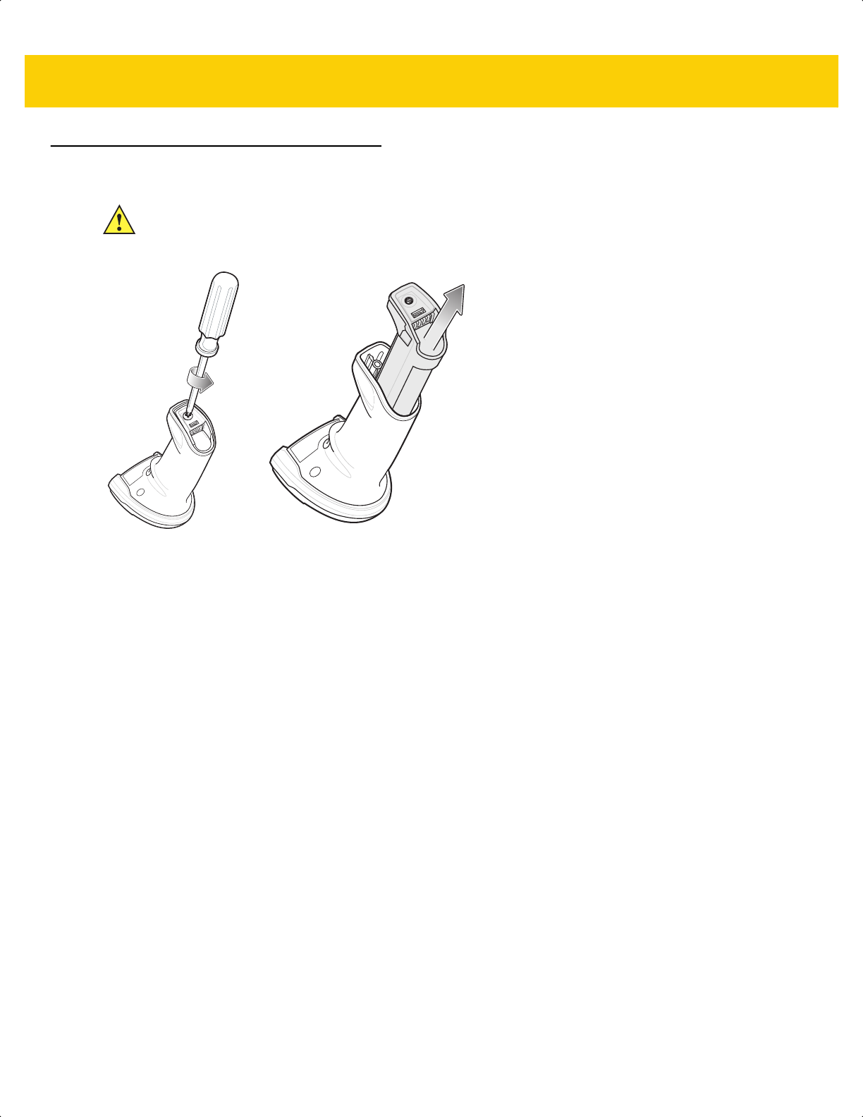
1 - 8 DS2278 Digital Scanner Product Reference Guide
Removing the Battery
Figure 1-6 Removing the Battery from the Digital Scanner
To remove the battery from the digital scanner:
1. Turn the screw on the battery compartment counterclockwise to remove the screw.
2. Remove the battery from the battery compartment.
3. To replace the battery, see Inserting the Battery on page 1-7.
IMPORTANT When replacing the battery, wait at least 5 seconds after removing the old battery before
inserting the new battery.
ds2278-prg-en.book Page 8

Getting Started 1 - 9
Inserting the Digital Scanner in the Cradle
To insert the digital scanner in the CR2278-PC cradle:
1. Insert the digital scanner straight down into the cradle top.
2. The digital scanner naturally rotates forward to engage the digital scanner contacts with the cradle contacts
Figure 1-7 Inserting the Digital Scanner in the CR2278-PC Cradle
Sending Data to the Host Computer
The cradle receives data from the digital scanner via a wireless radio connection and transmits it to the host
computer via the host cable. The digital scanner and cradle must be paired for successful wireless communication.
Pairing
Pairing registers a digital scanner to the cradle such that the digital scanner and cradle can exchange information.
Pair the digital scanner to the cradle either by inserting it in the cradle (if pair on contacts is enabled), or by
scanning the pairing bar code.
To pair the digital scanner with the cradle, insert the digital scanner in the cradle or scan the pairing bar code.
(Pairing on insertion into the cradle is enabled by default. See Pairing Methods on page 6-28.)
NOTE The pairing bar code that connects the digital scanner to a cradle is unique to each cradle.
Do not scan data or parameters until pairing completes.
ds2278-prg-en.book Page 9

1 - 10 DS2278 Digital Scanner Product Reference Guide
Lost Connection to Host
If scanned data does not transmit to the cradle's host, ensure that all cables are firmly inserted and the power
supply is connected to an appropriate AC outlet, if applicable. If scanned data still does not transmit to the host,
reestablish a connection with the host:
1. Disconnect the power supply from the cradle.
2. Disconnect the host interface cable from the cradle.
3. Wait three seconds.
4. Reconnect the host interface cable to the cradle.
5. Reconnect the power supply to the cradle, if the host requires.
6. Reestablish pairing with the cradle by inserting the digital scanner in the cradle or scan the pairing bar code.
(Pairing on insertion into the cradle is enabled by default. See Pairing Methods on page 6-28.)
Configuring the Digital Scanner
Use the bar codes in this manual or the 123Scan
configuration program to configure the digital scanner. See
Chapter 5, User Preferences & Miscellaneous Options and each host chapter for information about programming
the digital scanner using bar code menus. See Chapter 2, 123Scan and Software Tools to configure the digital
scanner using this configuration program. 123Scan includes a help file.
Radio Communications
The digital scanner can communicate with remote devices via Bluetooth, or by pairing with a cradle. For radio
communication parameters, detailed information about operational modes, Bluetooth and pairing, see Chapter 6,
Radio Communications.
Accessories
The digital scanner ships with the battery installed and the DS2278 Quick Start Guide. The following accessories
must be ordered separately:
• Cradle: Can be used for charging the digital scanner battery and host communication (see Presentation
Cradle on page 1-4).
• Micro USB cable: Can be used for charging the battery in the digital scanner, without a cradle.
• Replacement battery for the DS2278 digital scanner, if needed.
• Interface cable for the appropriate interface.
• Power supply, if the interface requires one.
See Related Product Line Configurations on page xx for the full list of accessories. Also see Configurations on
page xix for product and cradle configurations. For additional items, contact a local Zebra representative or
business partner.
ds2278-prg-en.book Page 10

CHAPTER 2 123SCAN AND
SOFTWARE TOOLS
Introduction
This chapter briefly describes the Zebra software tools available for customizing scanner operation.
123Scan
123Scan is a software tool that simplifies scanner setup and more.
Intuitive enough for first time users, the 123Scan wizard guides users through a streamlined setup process.
Settings are saved in a configuration file that can be printed as a single programming bar code for scanning,
emailed to a smart phone for scanning from its screen, or downloaded to the scanner using a USB cable.
Through 123Scan a user can accomplish the following.
• Configure a scanner using a wizard.
• Program the following scanner settings:
• Beeper tone / volume settings.
• Enable / disable symbologies.
• Communication settings.
• Modify data before transmission to a host using:
• Advanced Data Formatting (ADF) - Scan one bar code per trigger pull.
• Load parameter settings to a scanner via:
• Bar code scanning.
• Scan a paper bar code.
• Scan a bar code from a PC screen.
• Scan a bar code from a smart phone screen.
• Download over a USB cable:
• Load settings to one scanner.
• Stage up to 10 scanners simultaneously (Powered USB Hub recommended with 0.5 amp / port).
ds2278-prg-en.book Page 1

2 - 2 DS2278 Digital Scanner Product Reference Guide
• Validate scanner setup:
• View scanned data within the utility's Data View screen.
• Review settings using the Parameter Report.
• Clone settings from an already deployed scanner from the start screen.
• Upgrade scanner firmware:
• Stage up to 10 scanners simultaneously (Powered USB Hub recommended with 0.5 amp / port).
• Upgrade firmware
• Over a USB cable
• Over a Bluetooth connection (no cradle required)
• View statistics such as:
• Asset tracking information.
• Time and usage information.
• Bar codes scanned by symbology.
• Generate the following reports:
• Bar Code Report - Programming bar code, included parameter settings, and supported scanner models.
• Parameter Report - Lists parameters programmed within a configuration file.
• Inventory Report - Lists scanner asset tracking information.
• Validation Report - Printout of scanned data from the Data view.
• Statistics Report - Lists all statistics retrieved from the scanner.
For more information go to: www.zebra.com/123Scan
.
Communication with 123Scan
Use a USB cable to connect the scanner to a Windows host computer running 123Scan.
123Scan Requirements
• Host computer with Windows 7, 8, or 10
• Scanner
123Scan Information
For more information on123Scan, go to: www.zebra.com/123Scan.
For a 1 minute tour of 123Scan, go to: www.zebra.com/ScannerHowToVideos
.
To see a list of all of our free software tools, go to: www.zebra.com/scannersoftware
.
ds2278-prg-en.book Page 2

123Scan and Software Tools 2 - 3
Scanner SDK, Other Software Tools, and Videos
To tackle all scanner programming needs, use Zebra’s diversified set of software tools. Whether staging a device
or developing a fully featured application with image and data capture, as well as asset management, these tools
help you every step of the way. To download any of the following free tools, go to:
www.zebra.com/scannersoftware.
• 123Scan configuration utility
• SDKs
• Scanner SDK for Windows
• Scanner SDK for Linux
• Scanner SDK for Android
• Scanner SDK for iOS
• Drivers
• OPOS driver
• JPOS driver
• USB CDC driver
• TWAIN driver
• Scanner Management Service (SMS) for Remote Management
• Windows
• Linux
• Mobile Apps
• Scanner Control App
• Android
• iOS
• Zebra AppGallery
• Scan-To-Connect Utility
• Android
• Windows
• How-To-Videos
NOTE For a list of SDK supported scanner functionality by communication protocol, see
Appendix J, Communication Protocol Functionality.
ds2278-prg-en.book Page 3

2 - 4 DS2278 Digital Scanner Product Reference Guide
Scanner Control App
The Scanner Control App (SCA) allows you to control a Bluetooth scanner from a phone or tablet without a cradle.
Use this app to showcase Zebra Bluetooth scanner capabilities and ease of control right from your phone.
The Scanner Control App supports Scan-To-Connect technology for one-step Bluetooth pairing and allows you to
control the following scanner functions:
• Program the beeper and LEDs
• Enable and disable symbologies
• Remotely trigger a scan
The app displays scanned bar code data, and can query scanner asset information and battery health statistics.
The Scanner Control App also works with USB connected scanners like the MP7000, assuming your Android tablet
has a powered USB host port.
The Scanner Control app is available on the Android Play, iOS App, and Zebra AppGallery stores. Source code is
available within the Zebra Scanner SDK for Android and iOS.
To watch a 1 minute tour of the Scanner Control App, go to: www.zebra.com/scannercontrolapp
.
Scan-To-Connect (STC) Utility
In one step, connect a Zebra Bluetooth scanner to a phone, tablet or PC by simply scanning an STC bar code.
Available as a standalone utility for Windows and Android operating systems from www.zebra.com/scantoconnect.
Source code is also available for easy app integration.
NOTE The STC utility allows you to pair a Bluetooth scanner to a phone, tablet or PC without using a cradle.
ds2278-prg-en.book Page 4

CHAPTER 3 DATA CAPTURE
Introduction
This chapter provides beeper and LED definitions, techniques involved in scanning bar codes, general instructions
and tips about scanning, and decode ranges.
Beeper and LED Indications
The digital scanner issues different beep sequences/patterns and an LED display to indicate status. Table 3-1
defines beep sequences/patterns and LED displays which occur during both normal scanning and while
programming the digital scanner.
Digital Scanner Indications
Table 3-1 Digital Scanner Beeper and LED Indications
Beeper Sequence LED Indication
Standard Use
Low/medium/high beeps Green Power up.
Scanning
None Green solid Presentation Mode on.
None No LED; green LED is
turned off
Presentation Mode off.
Medium beep
(or as configured)
Green flash A bar code was successfully decoded. (See
User
Preferences/Miscellaneous Options Parameter
Defaults on page 5-2
for programming beeper sounds.)
Low/low/low/extra low
beeps
Red Parity error.
ds2278-prg-en.book Page 1

3 - 2 DS2278 Digital Scanner Product Reference Guide
Four long low beeps Red A transmission error was detected in a scanned symbol.
The data is ignored. This occurs if a unit is not properly
configured. Check option setting.
Five long low beeps Red Conversion or format error.
None Red (fast blink)) on
trigger pull
Digital scanner is disabled by a host command to the
digital scanner.
High None A <BEL> character is received over RS-232.
None Single green flash Scanner dock in the cradle.
Wireless Operation
Low, high, low, high Red Out of batch storage memory, unable to store new bar
code.
Radio Indications
Low None Digital scanner inserted into a cradle (may be disabled).
Low, high Green Bluetooth connection established.
High, low Red Bluetooth disconnection event.
Long low, long high Red Bluetooth page timeout; remote device is out of
range/not powered.
Long low, long high, long
low, long high
None Bluetooth connection attempt was rejected by remote
device.
None Green (fast blink) Bluetooth attempting reconnection.
Five high Green (fast blink) Bluetooth attempting reconnection (default is disable).
None Green (fast blink) Digital scanner placed into limited discoverable mode.
High, Low, High, Low Green Pairing bar code scanned.
Battery Indications
Four short high beeps Red (stays on for 4
seconds)
Low battery indication (on trigger release).
None Solid green Digital scanner is charging.
None Red (solid) Digital scanner charging error occurred.
Battery Indications - Micro USB Only
None Green (fast continuous
blink)
Digital scanner is charging.
None Green (solid) Digital scanner is fully charged.
None Single green flash Initial connection.
None Red (solid) Charge error.
Table 3-1 Digital Scanner Beeper and LED Indications (Continued)
Beeper Sequence LED Indication
ds2278-prg-en.book Page 2

Data Capture 3 - 3
Parameter Programming
Long low/long high beeps Red Input error, incorrect bar code or Cancel scanned,
wrong entry, incorrect bar code programming
sequence; remain in program mode.
High/low beeps Green Keyboard parameter selected. Enter value using bar
code keypad.
High/low/high/low beeps Green Successful program exit with change in the parameter
setting.
ADF Programming
Low/high/low beeps None ADF transmit error.
High/low beeps Green Number expected. Enter another digit. Add leading
zeros to the front if necessary.
Low/low beeps Green Alpha expected. Enter another alphabetic character or
scan the End of Message bar code.
High/high beeps Green blinking ADF criteria or action is expected. Enter another criteria
or action or scan the Save Rule bar code.
High/low/low beeps Green All criteria or actions cleared for current rule, continue
entering rule.
High/low/high/low beeps Green
(turns off blinking)
Rule saved. Rule entry mode exited.
Long low/long high beeps Red Rule error. Entry error, wrong bar code scanned, or
criteria/action list is too long for a rule. Re-enter criteria
or action.
Low beep Green Deleted last saved rule. The current rule is left intact.
Low/high/high beeps Green All rules deleted.
Long low/long high/long
low/long high beeps
Red Out of rule memory. Erase some existing rules, then try
to save rule again.
Long low/long high/long low
beeps
Green
(turns off blinking)
Cancel rule entry. Rule entry mode exited because of
an error or the user asked to exit rule entry.
Macro PDF
Two low beeps None File ID error. A bar code not in the current MPDF
sequence was scanned.
Two long low beeps None File ID error. A bar code not in the current MPDF
sequence was scanned.
Three long low beeps None Out of memory. There is not enough buffer space to
store the current MPDF symbol.
Table 3-1 Digital Scanner Beeper and LED Indications (Continued)
Beeper Sequence LED Indication
ds2278-prg-en.book Page 3

3 - 4 DS2278 Digital Scanner Product Reference Guide
Four long low beeps None Bad symbology. Scanned a 1D or 2D bar code in a
MPDF sequence, a duplicate MPDF label, a label in
an incorrect order, or trying to transmit an empty or
illegal MPDF field.
Five long low beeps None Flushing MPDF buffer.
Fast warble beep None Aborting MPDF sequence.
Low/high beeps None Flushing an already empty MPDF buffer.
Host Specific
USB only
Four high beeps None
Digital
scanner has not completed initialization. Wait
several seconds and scan again.
RS-232 only
High/high/high/low beeps Red RS-232 receive error.
High beep None A <BEL> character is received when Beep on <BEL> is
enabled.
Host Controlled Digital Scanner LEDs
None Green (slow blink) Digital scanner connected to 123Scan.
None Red (fast blink) File being transferred to the digital scanner (parameters
and firmware).
None Red (slow blink) Firmware being activated on the digital scanner, loaded
into memory.
None Green (solid) Programming completed successfully (parameters and
firmware).
None Red (blink) Loading the SMS package to the digital scanner.
None Red (solid) Error state.
Table 3-1 Digital Scanner Beeper and LED Indications (Continued)
Beeper Sequence LED Indication
ds2278-prg-en.book Page 4

Data Capture 3 - 5
Cradle LED Indications
Table 3-3 lists the conditions in which the specified host controls the System Indicator LED.
Table 3-2 Cradle LED Indications
LED Indication
Standard Use
Green (solid) Power up.
Green (off, then on) Bluetooth connection established.
Red (blink) Transmission error.
Charging
Amber (blink) Charging.
Green (solid) Fully charged.
Amber (fast blink) Charging error.
Maintenance
Red (solid) Enter boot loader.
Red (blink) Firmware installation.
Table 3-3 Host Controlled Cradle LED Indications
LED Indication
123Scan
Slow Blinking Green Digital scanner connected to 123Scan.
Fast Blinking Red File being transferred to the digital scanner (parameters and firmware).
Slow Blinking Red Firmware activated on the digital scanner, loaded into memory.
Solid Green Programming completed successfully (parameters and firmware).
Solid Red Error state.
SMS
Blinking Red
(Both digital scanner and cradle)
Loading the SMS package to digital scanner.
ds2278-prg-en.book Page 5
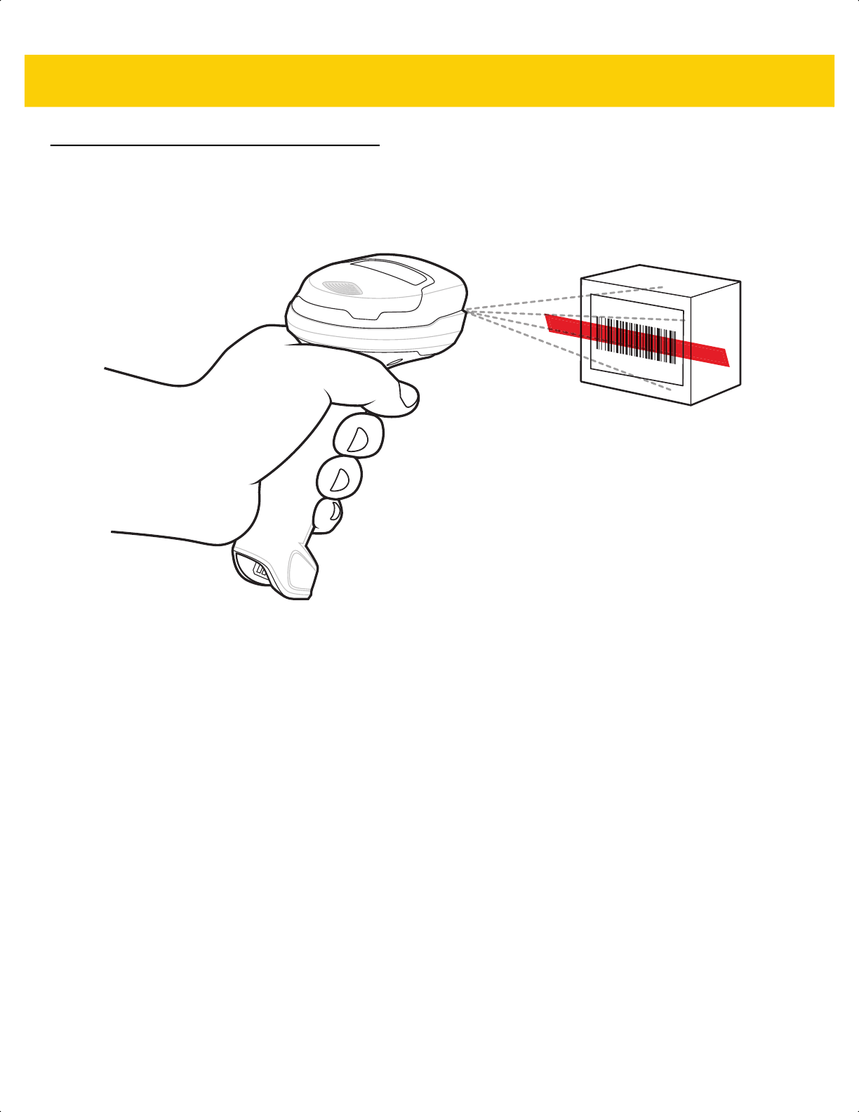
3 - 6 DS2278 Digital Scanner Product Reference Guide
Scanning
Hand-Held Scanning
1. Place the aiming pattern over the bar code.
Figure 3-1 Aiming Pattern on Bar Code - Hand-Held Mode
2. Press and hold the trigger until either:
a. The digital scanner reads the bar code. The digital scanner beeps, the LED flashes, and the scan line turns
off.
Or
b. The digital scanner does not read the bar code and the scan line turns off.
3. Release the trigger.
ds2278-prg-en.book Page 6
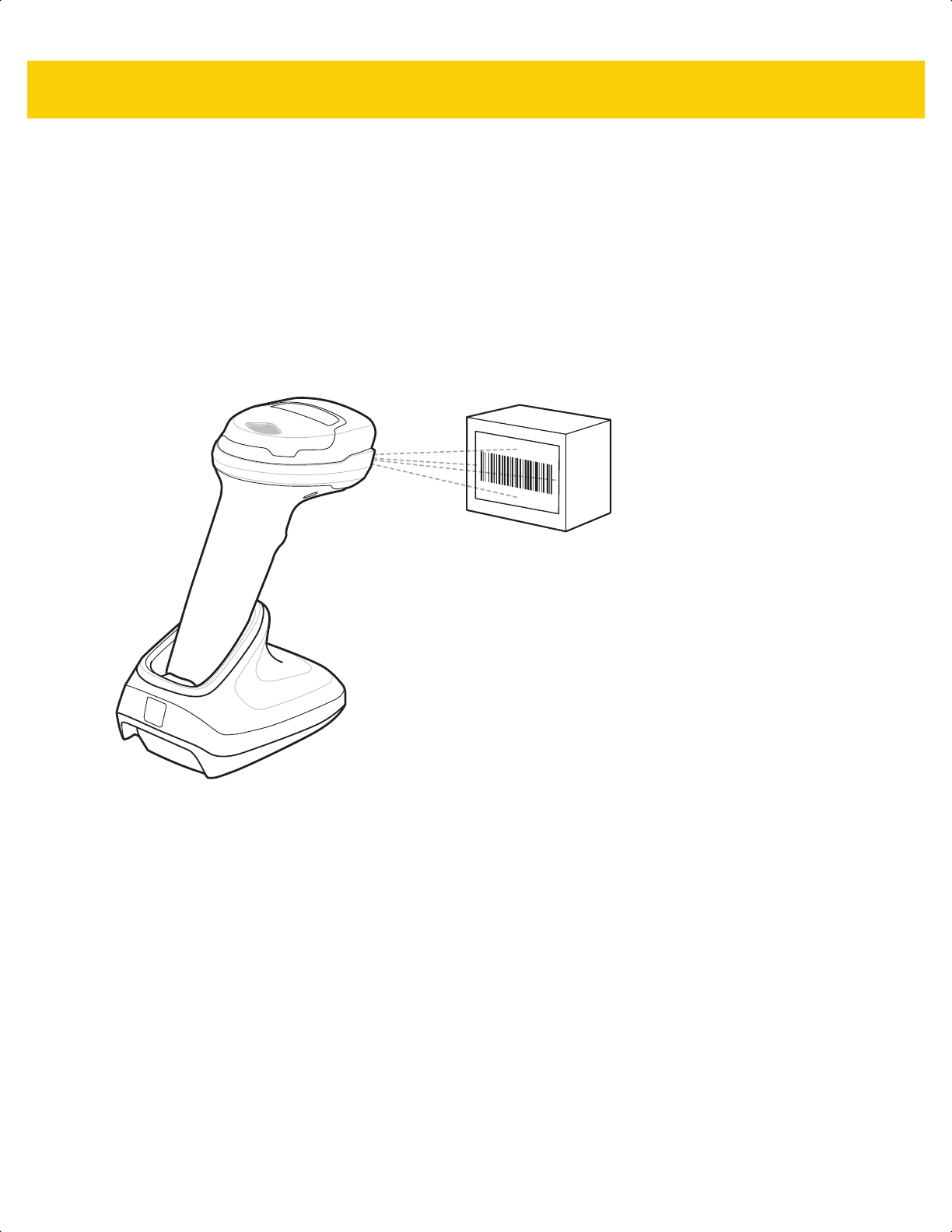
Data Capture 3 - 7
Hands-Free Scanning
The digital scanner is in hands-free (presentation) mode when it sits in the CR2278-PC cradle. During idle
conditions the digital scanner operates in object detection mode, where it automatically wakes up to decode a bar
code presented in the field of view. In object detection mode it is normal for the illumination LEDs to be dimly lit.
To scan:
1. Ensure all connections are secure (see appropriate host chapter).
2. Present the bar code in the digital scanner field of view.
3. Upon successful decode, the digital scanner beeps and the LED flashes green. (For more information about
beeper and LED definitions, Beeper and LED Indications on page 3-1).
Figure 3-2 Aiming Pattern on Bar Code - Hands-Free Mode
ds2278-prg-en.book Page 7
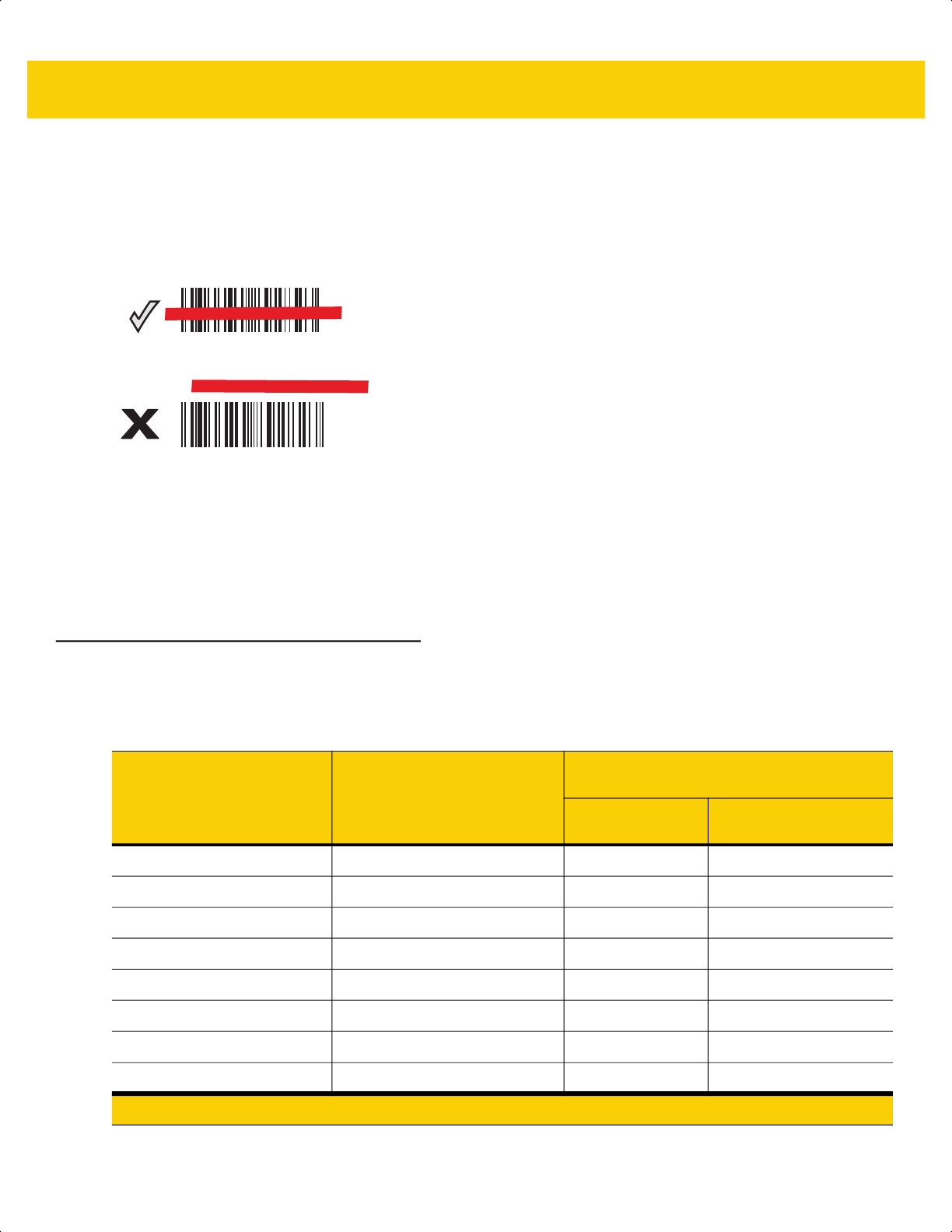
3 - 8 DS2278 Digital Scanner Product Reference Guide
Aiming with Digital Scanner
Aiming
When scanning, the digital scanner projects a red scan line which allows positioning the bar code within its field of
view, omnidirectionally. See Decode Ranges on page 3-8 for the proper distance to achieve between the digital
scanner and a bar code.
Figure 3-3 Scanning Orientation with Aiming Line
The aiming line is smaller when the digital scanner is closer to the symbol and larger when it is farther from the
symbol. Scan symbols with smaller bars or elements (mil size) closer to the digital scanner, and those with larger
bars or elements (mil size) farther from the digital scanner.
The digital scanner beeps to indicate that it successfully decoded the bar code. For more information see Table 3-1
on page 3-1.
Decode Ranges
012345
012345
Table 3-4 DS2278 Typical Decode Ranges
Bar Code Type Symbol Density
DS2278
Typical Working Ranges
Near
(in/cm)
Far
(in/cm)
Code 39 5 mil .2 in/.5 cm 6.0 in/15.2 cm
Code 39 10 mil .0 in/.0 cm 13.0 in/33.0 cm
Code 128 5 mil .6 in/1.5 cm 4.0 in/10.1 cm
Code 128 7.5 mil .0 in/.0 cm 7.0 in/17.8 cm
PDF417 6.7 mil .8 in/2.0 cm 5.7 in/14.5 cm
UPC 13 mil (100%) .5 in/1.3 cm 14.5 in/36.8 cm
Data Matrix 10 mil .3 in/.8 cm 6.2 in/15.7 cm
QR 20 mil .0 in/.0 cm 11.0 in/27.9 cm
* Printing resolution, contrast, and ambient light dependent.
ds2278-prg-en.book Page 8

CHAPTER 4 MAINTENANCE,
TROUBLESHOOTING, &
TECHNICAL
SPECIFICATIONS
Introduction
This chapter provides suggested digital scanner maintenance, troubleshooting, technical specifications, and signal
descriptions (pinouts).
Maintenance
Known Harmful Ingredients
The following chemicals are known to damage the plastics on Zebra scanners and should not come in contact with
the device:
• Acetone
• Ammonia solutions
• Aqueous or alcoholic alkaline solutions
• Aromatic and chlorinated hydrocarbons
• Benzene
• Carbolic acid
• Compounds of amines or ammonia
• Ethanolamine
• Ethers
• Isopropyl alcohol 70% (including wipes)
• Ketones
• TB-lysoform
• Toluene
• Trichloroethylene.
IMPORTANT Use pre-moistened wipes and do not allow liquid cleaner to pool.
ds2278-prg-en.book Page 1

4 - 2 DS2278 Digital Scanner Product Reference Guide
Approved Cleaners for the Digital Scanner and Cradle
• Hydrogen peroxide
• Mild dish soap.
Cleaning the Digital Scanner
Routinely cleaning the exit window is required. A dirty window may affect scanning accuracy. Do not allow any
abrasive material to touch the window.
To clean the digital scanner:
1. Dampen a soft cloth with one of the approved cleaning agents listed above or use pre-moistened wipes.
2. Gently wipe all surfaces, including the front, back, sides, top and bottom. Never apply liquid directly to the
digital scanner. Be careful not to let liquid pool around the digital scanner window, trigger, cable connector or
any other area on the device.
3. Be sure to clean the trigger and in between the trigger and the housing (use a cotton-tipped applicator to reach
tight or inaccessible areas).
4. Do not spray water or other cleaning liquids directly into the exit window.
5. Wipe the digital scanner exit window with a lens tissue or other material suitable for cleaning optical material
such as eyeglasses.
6. Immediately dry the digital scanner window after cleaning with a soft non-abrasive cloth to prevent streaking.
7. Allow the unit to air dry before use.
8.
Digital s
canner connectors:
a. Dip the cotton portion of a cotton-tipped applicator in an approved cleaner.
b. Rub the cotton portion of the cotton-tipped applicator back-and-forth across the connector on the Zebra
digital scanner at least 3 times. Do not leave any cotton residue on the connector.
c. Use the cotton-tipped applicator dipped in alcohol to remove any grease and dirt near the connector area.
d. Use a dry cotton tipped applicator and rub the cotton portion of the cotton-tipped applicator back-and-forth
across the connectors at least 3 times. Do not leave any cotton residue on the connectors.
ds2278-prg-en.book Page 2

Maintenance, Troubleshooting, & Technical Specifications 4 - 3
Troubleshooting
Table 4-1 Troubleshooting
Problem Possible Causes Possible Solutions
The aiming pattern does not
appear when pressing the
trigger.
No power to the digital scanner. If the configuration requires a power
supply, re-connect the power supply.
Incorrect host interface cable is
used.
Connect the correct host interface cable.
Interface/power cables are loose. Re-connect cables.
Digital scanner is disabled. For IBM 468x and USB IBM Hand-held,
IBM Table-Top, and OPOS modes, enable
the digital scanner via the host interface.
Otherwise, see the technical person in
charge of scanning.
If using RS-232 Nixdorf B mode,
CTS is not asserted.
Assert CTS line.
Aiming pattern is disabled. Enable the aiming pattern. See Hand-Held
Decode Aiming Pattern on page 5-18.
Digital scanner emits aiming
pattern, but does not decode
the bar code.
Digital scanner is not programmed
for the correct bar code type.
Program the digital scanner to read that
type of bar code. See Chapter 13,
Symbologies.
Bar code symbol is unreadable. Scan test symbols of the same bar code
type to determine if the bar code is
defaced.
The symbol is not completely inside
aiming pattern.
Move the symbol completely within the
aiming pattern.
Move the symbol completely within the
field of view (AIM pattern does NOT define
FOV)
Distance between digital scanner
and bar code is incorrect.
Move the digital scanner closer to or
further from the bar code. See Decode
Ranges on page 3-8.
ds2278-prg-en.book Page 3

4 - 4 DS2278 Digital Scanner Product Reference Guide
Digital scanner decodes bar
code, but does not transmit
the data to the host.
Digital scanner is not programmed
for the correct host type.
Scan the appropriate host type
programming bar code. See the chapter
corresponding to the host type.
Interface cable is loose. Re-connect the cable.
Cradle is not programmed for the
correct host type.
Check digital scanner host parameters or
edit options.
Digital scanner is not paired to host
connected interface.
Pair digital scanner to the cradle by
scanning the PAIR bar code on the cradle.
Cradle has lost connection to the
host.
In this exact order: disconnect power
supply; disconnect host cable; wait three
seconds; reconnect host cable; reconnect
power supply; reestablish pairing.
If the digital scanner emits four long
low beeps, a transmission error
occurred.
This occurs if a unit is not properly
configured or connected to the
wrong host type.
Set the digital scanner's communication
parameters to match the host's setting.
If the digital scanner emits five low
beeps, a conversion or format error
occurred.
Configure the digital scanner's conversion
parameters properly.
If the digital scanner emits
low/high/low beeps, it detected an
invalid ADF rule.
Program the correct ADF rules. Refer to
the Advanced Data Formatting
Programmer Guide.
Host displays scanned data
incorrectly.
Digital scanner is not programmed
to work with the host.
Scan the appropriate host type
programming bar code.
For RS-232, set the digital scanner's
communication parameters to match the
host's settings.
For a Keyboard Wedge configuration,
program the system for the correct
keyboard type, and turn off the CAPS
LOCK key.
Program the proper editing options (e.g.,
UPC-E to UPC-A Conversion).
Digital scanner emits short
low/short medium/short high
beep sequence (power-up
beep sequence) more than
once.
The USB bus may put the digital
scanner in a state where power to
the digital scanner is cycled on and
off more than once.
Normal during host reset.
Table 4-1 Troubleshooting (Continued)
Problem Possible Causes Possible Solutions
ds2278-prg-en.book Page 4

Maintenance, Troubleshooting, & Technical Specifications 4 - 5
Digital scanner emits four
short high beeps during
decode attempt.
Digital scanner has not completed
USB initialization.
Wait several seconds and scan again.
Digital scanner emits
Low/low/low/extra low beeps
when not in use.
RS-232 receive error. Normal during host reset. Otherwise, set
the digital scanner's RS-232 parity to
match the host setting.
Digital scanner emits
low/high beeps during
programming.
Input error, incorrect bar code or
Cancel bar code was scanned.
Scan the correct numeric bar codes within
range for the parameter programmed.
Digital scanner emits
low/high/low/high beeps
during programming.
Out of host parameter storage
space.
Scan Default Parameters on page 5-5.
Out of memory for ADF rules. Reduce the number of ADF rules or the
number of steps in the ADF rules.
During programming, indicates out
of ADF parameter storage space.
Erase all rules and re-program with shorter
rules.
Digital scanner emits
low/high/low beeps.
ADF transmit error. Refer to the Advanced Data Formatting
Guide for information.
Invalid ADF rule is detected. Refer to the Advanced Data Formatting
Guide for information.
Digital scanner emits a
power-up beep after
changing USB host type.
The USB bus re-established power
to the digital scanner.
Normal when changing USB host type.
Digital scanner emits one
high beep when not in use.
In RS-232 mode, a <BEL>
character was received and Beep
on <BEL> option is enabled.
Normal when Beep on <BEL> is enabled
and the digital scanner is in RS-232 mode.
Digital scanner emits
frequent beeps.
No power to the digital scanner. Check the system power. If the
configuration requires a power supply,
re-connect the power supply.
Incorrect host interface cable is
used.
Verify that the correct host interface cable
is used. If not, connect the correct host
interface cable.
Interface/power cables are loose. Check for loose cable connections and
re-connect cables.
Table 4-1 Troubleshooting (Continued)
Problem Possible Causes Possible Solutions
ds2278-prg-en.book Page 5

4 - 6 DS2278 Digital Scanner Product Reference Guide
Digital scanner emits five
long low beeps after a bar
code is decoded.
Conversion or format error was
detected.
The digital scanner’s conversion
parameters are not properly
configured.
Ensure the digital scanner’s conversion
parameters are properly configured.
Conversion or format error was
detected.
An ADF rule was set up with
characters that can't be sent for the
host selected.
Change the ADF rule, or change to a host
that can support the ADF rule.
Conversion or format error was
detected.
A bar code was scanned with
characters that can't be sent for that
host.
Change the bar code, or change to a host
that can support the bar code.
The digital scanner does not
connect to the
tablet/PC/phone using a
Bluetooth Serial connection
(SPP) or while emulating a
Bluetooth keyboard (HID).
N/A 1.Turn off and then turn back on the
Bluetooth radio on the tablet/PC/phone.
A reboot of the tablet/PC/phone may be
required.
or
2. Remove the device from the PC. Scan
Set Factory Defaults on page 5-5 and
reconfigure the digital scanner from
scratch.
When trying to pair the
digital scanner and cradle by
scanning the pairing bar
code on the CR2278, the
digital scanner emits a
rejection beep.
Pairing attempt occurs after
scanning Set Factory Defaults.
After scanning Set Factory Defaults
either insert the digital scanner in the
cradle to pair or wait five seconds before
scanning the pairing bar code on the
cradle.
Digital s
canner LED blinks
even if the pairing request
was canceled from remote
iOS/Android device.
If pass key entry is canceled from
the tablet/phone, the digital scanner
remains in the pass key entry mode
for 30 seconds before timing out.
To exit pass key entry mode scan Cancel
on page H-1 or scan any other bar code.
There is a delay before
illumination and aim turn on
after a trigger pull.
N/A Increase Time Delay to Low Power Mode
on page 5-12 to help with radio wake up.
Note: This could impact overall battery
life.
There are firmware update
failures (the firmware
download does not go
through).
N/A Increase Time Delay to Low Power Mode
on page 5-12 to help with radio wake up.
Table 4-1 Troubleshooting (Continued)
Problem Possible Causes Possible Solutions
ds2278-prg-en.book Page 6

Maintenance, Troubleshooting, & Technical Specifications 4 - 7
Report Software Version Bar Code
When contacting support, a support representative may ask you to scan the bar code below to determine the
version of software installed in the digital scanner.
NOTE If after performing these checks the digital scanner still experiences problems, contact the distributor or
call support.
Report Software Version
ds2278-prg-en.book Page 7

4 - 8 DS2278 Digital Scanner Product Reference Guide
Technical Specifications
Table 4-2 Technical Specifications
Item Description
Physical Characteristics
Dimensions
Digital s
canner
Presentation Cradle
6.9 in. H x 2.6 in. W x 3.5 in. D
17.5 cm. H x 6.6 cm. W x 9.0 cm. D
2.8 in. H x 3.7 in. W x 4.8 in. D
7.2 cm. H x 9.4 cm. W x 12.2 cm. D
Weight
Digital s
canner
Presentation Cradle
7.5 oz. / 214 g
5.2 oz. / 151 g
Input Voltage Range (DS2278 and Cradle) 4.5 to 5.5 VDC Host Powered; 4.5 to 5.5 VDC External Power Supply
Current (Presentation Cradle and Micro USB
Cable)
500 mA (typical) Standard USB; 1100 mA (typical) BC 1.2 USB
Color Nova White, Twilight Black
Supported Host Interfaces USB, RS-232, Keyboard Wedge, TGCS (IBM) 46XX over RS-485
USB Certification DS2278 is USB2.0 Full Speed Compliant, visit USB.org
for more
details.
Keyboard Support Supports over 90 international keyboards
User Indicators Direct Decode Indicator, Good Decode LEDs, Rear View LEDs,
Beeper (adjustable tone and volume)
Performance Characteristics
Motion Tolerance (Hand-Held) Up to 5 in./13 cm. per second for 13 mil UPC
Swipe Speed (Hands-Free) Up to 30.0 in./76.2 cm. per second for 13 mil UPC
Aiming Pattern Linear 624nm Amber LED
Illumination Two 645nm Super-Red LEDs
Imager Field of View 32.8° H x 24.8° V Nominal
Image Sensor 640 x 480 pixels
Minimum Print Contrast 25% minimum reflective difference
Skew Tolerance +/- 65°
Pitch Tolerance +/- 65°
Roll Tolerance 0° - 360°
ds2278-prg-en.book Page 8

Maintenance, Troubleshooting, & Technical Specifications 4 - 9
User Environment
Operating Temperature
Digital s
canner
Presentation Cradle
32.0° to 122.0° F/0.0° to 50.0° C
32.0° to 104.0° F/0.0° to 40.0° C
Storage Temperature -40.0° to 158.0° F/-40.0° to 70.0° C
Humidity 5% to 95% RH, non-condensing
Drop Specification Designed to withstand multiple drops at 5.0 ft./1.5 m to concrete
Tumble Specification Designed to withstand 250 tumbles in 1.5 ft./.5 m tumbler
Note: 1 tumble = 0.5 cycle
Environmental Sealing IP52
Electrostatic Discharge (ESD) DS2278 and Presentation Cradle: ESD per EN61000-4-2, +/-15 KV
Air, +/-8 KV Direct, +/-8 KV Indirect
Ambient Light Immunity 0 to 10,000 Foot Candles / 0 to 107,600 Lux
Radio Specifications
Bluetooth Radio Standard Bluetooth Version 4.0 with BLE:
Direct line of sight in open air: Class 2: Minimum 30 ft. (10.0 m) and
up to 300 ft. (100.0 m) when paired with CR2278 cradle.
Environmental factors may impact results. Serial Port and HID
Profiles; output power adjustable down from 2.0 dBm in 8 steps.
Battery
Battery Capacity/Battery Type 2,400 mAh Li-Ion Battery
Scans Per Battery Charge 110,000 scans at 60 scans per minute or 50,000 scans at 10 scans
per minute
Note: Simulated Checkout profile of 10 scans in 10 seconds with a 50
second rest.
Operating Time Per Full Charge 84.0 hours
Note: Simulated Checkout profile of 10 scans in 10 seconds with a 50
second rest.
Charge Time (from Empty)
Standard USB
BC1.2 USB
External 5V Source
Micro USB
BC1.2 Micro USB
14 Hour Shift Hours Full Charge Hours
4 17
1 5
1 5
1.5 7
1 4
Table 4-2 Technical Specifications (Continued)
Item Description
ds2278-prg-en.book Page 9

4 - 10 DS2278 Digital Scanner Product Reference Guide
Symbol Decode Capability
1D Code 39, Code 128, Code 93, Codabar/NW7, Code 11, MSI Plessey,
UPC/EAN, Interleaved 2 of 5, Korean 3 of 5, GS1 DataBar, Base 32
(Italian Pharma)
2D PDF417, Composite Codes, TLC-39, Aztec, DataMatrix, MaxiCode,
QR Code, Micro QR, Han Xin (Chinese Sensible), Postal Codes
Minimum Element Resolution
Code 39 4.0 mil
Code 128 4.0 mil
Data Matrix 6.0 mil
QR Code 6.7 mil
Utilities and Management
123Scan Programs digital scanner parameters, upgrades firmware, provides
scanned bar code data and prints reports (see Chapter 2, 123Scan
and Software Tools).
Symbol Scanner SDK Generates a fully-featured scanner application, including
documentation, drivers, test utilities and sample source code
(www.zebra.com/ScannerSDKforWindows
)
Scanner Management Service (SMS) Remotely manages your Zebra scanner and queries its asset
information (www.zebra.com/sms
).
Table 4-2 Technical Specifications (Continued)
Item Description
ds2278-prg-en.book Page 10
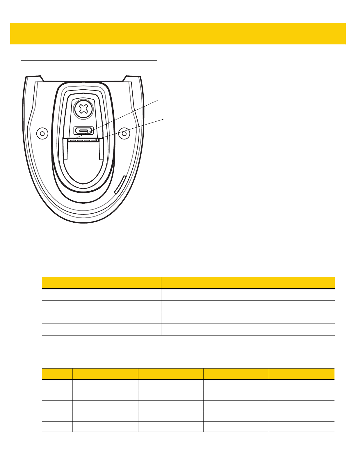
Maintenance, Troubleshooting, & Technical Specifications 4 - 11
Cradle Signal Descriptions
Figure 4-1 Cradle Pinouts
The signal descriptions in Table 4-3 apply to the contacts on the digital scanner and are for reference only.
The signal descriptions in Table 4-4 apply to the connectors on the DS2278 digital scanner and are for reference
only.
PIN 1
PIN 4
Table 4-3 Signal Pinouts
Pin Function
1 5VDC
2 USB_D-
3 USB_D+
4 Ground
Table 4-4 DS2278 Digital Scanner Signal Pin-outs
Pin USB RS-232 Keyboard Wedge IBM
1 Short to Pin 6 Reserved 1M Resistor to Pin 8 2M Resistor to Pin 8
2 Power Power Power Power
3 Ground Ground Ground Ground
4 Reserved TXD KBD_CLK IBM_TXD
5 D + RXD TERM_DATA IBM_RXD
ds2278-prg-en.book Page 11

4 - 12 DS2278 Digital Scanner Product Reference Guide
6 Short to Pin 1 RTS KBD_DATA IBM_DIR
7 D - CTS TERM_CLK Reserved
8 Reserved Reserved 1M Resistor to Pin 1 2M Resistor to Pin 1
9 Reserved Reserved Reserved Reserved
10 Reserved Reserved Reserved Reserved
SHELL Shield Shield Shield Shield
Table 4-4 DS2278 Digital Scanner Signal Pin-outs (Continued)
Pin USB RS-232 Keyboard Wedge IBM
ds2278-prg-en.book Page 12

CHAPTER 5 USER PREFERENCES &
MISCELLANEOUS
OPTIONS
Introduction
You can program the scanner to perform various functions, or activate different features. This chapter describes
user preference features and provides programming bar codes for selecting these features.
The scanner ships with the settings shown in Table 5-1 on page 5-2 (also see Appendix A, Standard Default
Parameters for all defaults). If the default values suit requirements, programming is not necessary.
Setting Parameters
To set feature values, scan a single bar code or a short bar code sequence. The settings are stored in non-volatile
memory and are preserved even when the scanner powers down.
If not using the default host, select the host type (see each host chapter for specific host information) after the
power-up beeps sound. This is only necessary upon the first power-up when connected to a new host.
To return all features to default values, see Default Parameters on page 5-5. Throughout the programming bar
code menus, asterisks indicate (
*) default values.
NOTE Most computer monitors allow scanning bar codes directly on the screen. When scanning from the screen,
be sure to set the document magnification to a level where you can see the bar code clearly, and bars
and/or spaces do not merge.
*Enable Parameter
(1)
Feature/option
* Indicates default
Option value
ds2278-prg-en.book Page 1

5 - 2 DS2278 Digital Scanner Product Reference Guide
Scanning Sequence Examples
In most cases, scanning one bar code sets the parameter value. For example, to set the beeper tone to high, scan
the High Frequency (beeper tone) bar code listed under Beeper Tone on page 5-8. The scanner issues a fast
warble beep and the LED turns green, signifying a successful parameter entry.
Other parameters, such as Serial Response Timeout or Data Transmission Formats, require scanning several
bar codes. See the parameter descriptions for this procedure.
Errors While Scanning
Unless otherwise specified, to correct an error during a scanning sequence, just re-scan the correct parameter.
User Preferences/Miscellaneous Options Parameter Defaults
Table 5-1 lists defaults for user preferences parameters. Change these values in one of two ways:
• Scan the appropriate bar codes in this chapter. The new value replaces the standard default value in
memory. To recall default parameter values, see Default Parameters on page 5-5.
• Configure the scanner using the 123Scan
configuration program. See Chapter 2, 123Scan and Software
Tools.
NOTE See Appendix A, Standard Default Parameters for all user preference, host, symbology, and
miscellaneous default parameters.
Table 5-1 User Preferences Parameter Defaults
Parameter
Parameter
Number
1
SSI
Number
2
Default
Page
Number
User Preferences
Set Default Parameter N/A N/A N/A
5-5
Parameter Bar Code Scanning 236 ECh Enable
5-6
Beep After Good Decode 56 38h Enable
5-6
Beeper Volume 140 8Ch High
5-7
Beeper Tone 145 91h Medium
5-8
Beeper Duration 628 F1h 74h Medium
5-9
Suppress Power Up Beeps 721 F1h D1h Do Not Suppress
5-9
LED on Good Decode 744 F1h E8h Enable
5-10
Direct Decode Indicator 859 F2h 5Bh Disable
5-10
Low Power Mode 128 80h Enable
5-11
Time Delay to Low Power Mode 146 92h 100 msec
5-12
1. Parameter number decimal values are used for programming via RSM commands.
2. SSI number hex values are used for programming via SSI commands.
ds2278-prg-en.book Page 2

User Preferences & Miscellaneous Options 5 - 3
Timeout to Low Power Mode from Auto Aim 729 F1h D9h 15 sec
5-14
Battery Preservation Mode 1765 F8h 06h E5h Enable
5-15
Trigger Mode (or Hand-Held Trigger Mode) 138 8Ah Standard (Level)
5-16
Hands-Free Mode 630 F1h 76h Enable
5-17
Hand-Held Decode Aiming Pattern 306 F0h 32h Enable
5-18
Hands-Free (Presentation) Decode Aiming
Pattern
590 F1h 4Eh Enable Hands-Free
(Presentation) Decode
Aiming Pattern on PDF
5-19
Picklist Mode 402 F0h 92h Disable Picklist Mode
Always
5-20
Continuous Bar Code Read 649 F1h 89h Disable
5-21
Unique Bar Code Reporting 723 F1h D3h Enable
5-21
Decode Session Timeout 136 88h 9.9 Seconds
5-22
Hands-Free Decode Session Timeout 400 F0 90 15
5-22
Timeout Between Decodes, Same Symbol 137 89h 0.5 Seconds
5-23
Timeout Between Decodes, Different
Symbols
144 90h 0.1 Seconds
5-23
Decode Mirror Images (Data Matrix Only) 537 F1h 19h Auto 5-24
Mobile Phone/Display Mode N/A N/A N/A
5-24
PDF Prioritization 719 F1h CFh Disable
5-25
PDF Prioritization Timeout 720 F1h D0h 200 ms
5-25
Decoding Illumination 298 F0h 2Ah Enable
5-26
Illumination Brightness 669 F1h 9Dh High
5-26
Low Light Scene Detection 810 F2h 2Ah Dim Illumination Low
Light Assist Scene
Detection
5-27
Motion Tolerance (Hand-Held Trigger Mode
Only)
858 F2h 5Ah Less
5-28
Product ID (PID) Type 1281 F8h 05h 01h Host Type Unique
5-29
Product ID (PID) Value 1725 F8h 06h BDh 0
5-29
ECLevel 1710 F8h 06h AEh 0
5-30
Table 5-1 User Preferences Parameter Defaults (Continued)
Parameter
Parameter
Number
1
SSI
Number
2
Default
Page
Number
1. Parameter number decimal values are used for programming via RSM commands.
2. SSI number hex values are used for programming via SSI commands.
ds2278-prg-en.book Page 3

5 - 4 DS2278 Digital Scanner Product Reference Guide
Miscellaneous Options
Enter Key N/A N/A N/A
5-31
Tab Key N/A N/A N/A
5-31
Transmit Code ID Character 45 2Dh None
5-32
Prefix Value 99, 105 63h, 69h 7013 <CR><LF>
5-33
Suffix 1 Value
Suffix 2 Value
98, 104
100, 106
62h, 68h
64h, 6Ah
7013 <CR><LF>
5-33
Scan Data Transmission Format 235 EBh Data As Is
5-34
FN1 Substitution Values 103, 109 67h, 6Dh 7013 <CR><LF>
5-36
Transmit “No Read” Message 94 5E Disable
5-37
Unsolicited Heartbeat Interval 1118 F8h 04h 5Eh Disable
5-38
Send Versions
Software Version N/A N/A N/A
5-39
Serial Number N/A N/A N/A
5-39
Manufacturing Information N/A N/A N/A
5-39
Table 5-1 User Preferences Parameter Defaults (Continued)
Parameter
Parameter
Number
1
SSI
Number
2
Default
Page
Number
1. Parameter number decimal values are used for programming via RSM commands.
2. SSI number hex values are used for programming via SSI commands.
ds2278-prg-en.book Page 4

User Preferences & Miscellaneous Options 5 - 5
User Preferences
Default Parameters
Scan one of the following bar codes to reset the scanner to its default settings as follows:
• Restore Defaults resets all default parameters as follows:
• If you configured custom default parameter values via the Write to Custom Defaults bar code, scanning
the Restore Defaults bar code restores these custom values.
• If you did not configure custom default parameter values, scanning the Restore Defaults bar code
restores the factory default values. See Appendix A, Standard Default Parameters for these values.
• Set Factory Defaults clears all custom default values and sets the factory default values. See Appendix A,
Standard Default Parameters for these values.
Write to Custom Defaults
To create a set of custom defaults, select the desired parameter values in this guide, and then scan Write to
Custom Defaults.
NOTE To pair the scanner and cradle after scanning Set Factory Defaults either insert the scanner in the cradle
to pair or wait five seconds before scanning the pairing bar code on the cradle.
Restore Defaults
Set Factory Defaults
Write to Custom Defaults
ds2278-prg-en.book Page 5

5 - 6 DS2278 Digital Scanner Product Reference Guide
Parameter Bar Code Scanning
Parameter # 236
SSI # ECh
Scan one of the following bar codes to select whether to enable or disable the decoding of parameter bar codes,
including the Set Defaults bar codes.
Beep After Good Decode
Parameter # 56
SSI # 38h
Scan one of the following bar codes to select whether or not the scanner beeps after a good decode.
If you select Disable Beep After Good Decode, the beeper still operates during parameter menu scanning and to
indicate error conditions.
*Enable Parameter Bar Code Scanning
(1)
Disable Parameter Bar Code Scanning
(0)
*Enable Beep After Good Decode
(1)
Disable Beep After Good Decode
(0)
ds2278-prg-en.book Page 6

User Preferences & Miscellaneous Options 5 - 7
Beeper Volume
Parameter # 140
SSI # 8Ch
Scan one of the following bar codes to select a beeper volume.
Low Volume
(2)
Medium Volume
(1)
*High Volume
(0)
ds2278-prg-en.book Page 7
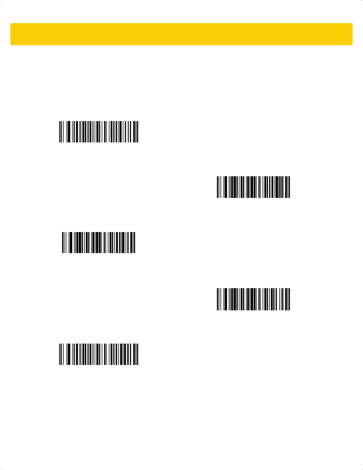
5 - 8 DS2278 Digital Scanner Product Reference Guide
Beeper Tone
Parameter # 145
SSI # 91h
Scan one of the following bar codes to select a beeper tone for the good decode beep.
Disable Tone
(3)
Low Tone
(2)
*Medium Tone
(1)
High Tone
(0)
Medium to High Tone (2-tone)
(4)
ds2278-prg-en.book Page 8

User Preferences & Miscellaneous Options 5 - 9
Beeper Duration
Parameter # 628
SSI # F1h 74h
Scan one of the following bar codes to select the duration for the good decode beep.
Suppress Power Up Beeps
Parameter # 721
SSI # F1h D1h
Scan one of the following bar codes to select whether or not to suppress the scanner’s power-up beeps.
Short Duration
(0)
*Medium Duration
(1)
Long Duration
(2)
*Do Not Suppress Power Up Beeps
(0)
Suppress Power Up Beeps
(1)
ds2278-prg-en.book Page 9

5 - 10 DS2278 Digital Scanner Product Reference Guide
LED on Good Decode
Parameter # 744
SSI # F1h E8h
Scan one of the following bar codes to select whether or not the LED blinks on a good decode.
Direct Decode Indicator
Parameter # 859
SSI # F2h 5Bh
This parameter is only supported in Auto Aim and Standard (Level) Trigger Mode. Scan one of the following bar
codes to select optional blinking of the illumination on a successful decode. You must continue to hold the trigger
upon decode to see the illumination blink. If you release the trigger upon decode, the blinking does not occur. If you
release the trigger upon decode, the blinking does not occur. This allows you to choose additional feedback for a
successful decode by holding the trigger, or to continue to scan as normal.
• *Disable Direct Decode Indicator - Illumination does not blink on a successful decode.
• 1 Blink - Illumination blinks once upon a successful decode.
• 2 Blinks - Illumination blinks twice upon a successful decode.
*Enable LED on Good Decode
(2)
Disable LED on Good Decode
(0)
*Disable Direct Decode Indicator
(0)
1 Blink
(1)
2 Blinks
(2)
ds2278-prg-en.book Page 10

User Preferences & Miscellaneous Options 5 - 11
Low Power Mode
Parameter # 128
SSI # 80h
Scan one of the following bar codes to select whether or not the scanner enters low power mode after a decode
attempt or host communication. This applies to serial and keyboard wedge connections. If disabled, power
remains on after each decode attempt.
If you enable this, see Time Delay to Low Power Mode to set the inactivity time period.
NOTE The Low Power Mode parameter only applies for non-USB and non-RS485 host interfaces, and when
Trigger Mode on page 5-16 is set to Level (Standard).
*Enable Low Power Mode
(1)
Disable Low Power Mode
(0)
ds2278-prg-en.book Page 11

5 - 12 DS2278 Digital Scanner Product Reference Guide
Time Delay to Low Power Mode
Parameter # 146
SSI # 92h
This parameter sets the time the digital scanner remains active before entering low power mode. The digital
scanner wakes upon trigger pull or when the host attempts to communicate with the digital scanner.
NOTE This parameter only applies when Low Power Mode is enabled.
*100 msec
(65)
500 msec
(69)
1 Second
(17)
2 sec
(18)
3 sec
(19)
4 sec
(20)
ds2278-prg-en.book Page 12

User Preferences & Miscellaneous Options 5 - 13
Time Delay to Low Power Mode (continued)
5 sec
(21)
10 sec
(26)
15 sec
(27)
ds2278-prg-en.book Page 13
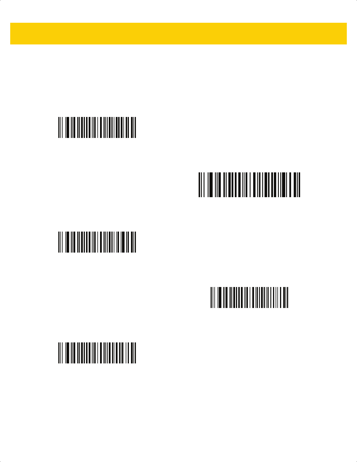
5 - 14 DS2278 Digital Scanner Product Reference Guide
Timeout to Low Power Mode from Auto Aim
Parameter # 729
SSI # F1 D9
This parameter sets the time the scanner remains in auto aim before entering Low Power Mode.
Disabled
(0)
5 sec
(5)
* 15 sec
(11)
30 sec
(13)
1 minute
(17)
ds2278-prg-en.book Page 14

User Preferences & Miscellaneous Options 5 - 15
Battery Preservation Mode
Parameter # 1765
SSI # F8h 06h E5h
Battery Preservation Mode preserves the battery charge when the digital scanner is not being used for an
extended period of time.
• Scan Enable Battery Preservation Mode to internally disconnect the battery from the digital scanner when
the digital scanner is unused and not being charged for nine hours
1
. In this mode the scanner completely
turns off. This preserves the battery charge as there is no current drain on the battery and significantly
extends battery shelf life. To exit Battery Preservation Mode
2
and return to normal operation either press the
digital scanner trigger or return to charging. The digital scanner cannot scan until the wake up process is
complete
3
. This takes a few seconds. The amount of time before the battery disconnects from the scanner
can be set via Battery Preservation Timeout Value below.
• Scan Disable Battery Preservation Mode to keep the battery connected to the digital scanner at all times.
This prevents the battery from being disconnected from the scanner after hours of sitting idle (no scanning)
and not charging. When Battery Preservation Mode is disabled, substantial battery shelf life improvements
are not gained as compared to when Battery Preservation Mode is enabled.
• Scan Battery Preservation Timeout followed by 3 digits in Appendix G, Numeric Bar Codes to select a
different battery preservation timeout value (the default for battery preservation timeout is nine hours). For
example, if the preservation timeout value should be 12 hours, scan Battery Preservation Timeout below,
then scan 0, 1, and 2 in Appendix G, Numeric Bar Codes. To correct an error or change the selection,
scan Cancel on page G-3.
NOTES
1
Nine hours is the default timeout value but can be changed via Battery Preservation Timeout Value.
2
Low Power Mode (5-11) must be enabled for Battery Preservation Mode to take effect.
3
When asleep in Battery Preservation Mode, the digital scanner cannot be accessed for remote
management.
*Enable Battery Preservation Mode
(9)
Disable Battery Preservation Mode
(0)
Battery Preservation Timeout Value
ds2278-prg-en.book Page 15

5 - 16 DS2278 Digital Scanner Product Reference Guide
Trigger Mode
Parameter # 138
SSI # 8Ah
Scan one of the following bar codes to select a trigger mode for the scanner:
• Standard (Level) - A trigger press activates decode processing. Decode processing continues until the bar
code decodes, you release the trigger, or the Decode Session Timeout on page 5-22 occurs.
• Presentation (Blink) - The scanner activates decode processing when it detects a bar code in its field of
view. After a period of non-use, the scanner illumination and aimer settings change due to the default Low
Light Scene Detection setting. The scanner re-activates decode processing when the scanner senses
motion.
• Auto Aim - The scanner projects the aiming pattern when lifted. A trigger press activates decode processing.
After two seconds of inactivity the aiming pattern shuts off.
*Standard (Level)
(0)
Presentation (Blink)
(7)
Auto Aim
(9)
ds2278-prg-en.book Page 16

User Preferences & Miscellaneous Options 5 - 17
Hands-Free Mode
Parameter # 630
SSI # F1h 76h
Scan one of the following bar codes to enable or disable
hands-free
mode:
• Enable Hands-Free Mode - When you place the scanner in a stand, it automatically triggers when
presented with a bar code. Lifting the scanner or pulling the trigger causes it to behave according to the
setting of the Trigger Mode on page 5-16.
• Disable Hands-Free Mode - The scanner behaves according to the setting of the Trigger Mode on page
5-16 regardless of whether it is hand-held or in stand.
*Enable Hands-Free Mode
(1)
Disable Hands-Free Mode
(0)
ds2278-prg-en.book Page 17

5 - 18 DS2278 Digital Scanner Product Reference Guide
Hand-Held Decode Aiming Pattern
Parameter # 306
SSI # F0h 32h
Scan one of the following bar codes to select when to project the aiming pattern in hand-held mode:
• Enable
Hand-Held Decode Aiming Pattern - This projects the aiming pattern during bar code capture.
• Disable Hand-Held Decode Aiming Pattern - This turns the aiming pattern off.
• Enable Hand-Held Decode Aiming Pattern on PDF - This projects the aiming pattern when the scanner
detects a PDF bar code.
NOTE With Picklist Mode on page 5-20 enabled, the decode aiming pattern flashes even if you disable the
Hand-Held Decode Aiming Pattern.
*Enable Hand-Held Decode Aiming Pattern
(2)
Disable Hand-Held Decode Aiming Pattern
(0)
Enable Hand-Held Decode Aiming Pattern on PDF
(3)
ds2278-prg-en.book Page 18

User Preferences & Miscellaneous Options 5 - 19
Hands-Free (Presentation) Decode Aiming Pattern
Parameter # 590
SSI # F1h 4Eh
Scan one of the following bar codes to select when to project the aiming pattern in hands-free mode:
• Enable Hands-Free
(Presentation) Decode Aiming Pattern - This projects the aiming pattern during bar
code capture.
• Disable Hands-Free (Presentation) Decode Aiming Pattern - This turns the aiming pattern off.
• Enable Hands-Free (Presentation) Decode Aiming Pattern on PDF - This projects the aiming pattern when
the scanner detects a PDF bar code.
NOTE With Picklist Mode on page 5-20 enabled, the decode aiming pattern flashes even when you disable the
Hands-Free Decode Aiming Pattern.
Enable Hands-Free (Presentation)
Decode Aiming Pattern
(1)
Disable Hands-Free (Presentation)
Decode Aiming Pattern
(0)
*Enable Hands-Free (Presentation)
Decode Aiming Pattern on PDF
(2)
ds2278-prg-en.book Page 19

5 - 20 DS2278 Digital Scanner Product Reference Guide
Picklist Mode
Parameter # 402
SSI # F0h 92h
Scan one of the following bar codes to select a Picklist Mode. In this mode, you can pick out and decode a bar
code from a group of bar codes that are printed close together by placing the aiming pattern on the bar code you
want to decode.
• Enable Picklist Mode Always - Picklist Mode is always enabled.
• Enable Picklist Mode in Hand-Held Mode - Picklist Mode is enabled when the scanner is out of hands-free
mode and disabled when the scanner is in presentation mode.
• Enable Picklist Mode in Hands-Free Mode - Picklist Mode is enabled when the scanner is in hands-free
mode only.
• Disable Picklist Mode Always - Picklist Mode is always disabled.
NOTE Enabling Picklist Mode overrides the Disable Decode Aiming Pattern options. You can not disable the
decode aiming pattern when Picklist Mode is enabled.
Enabling Picklist Mode can slow decode speed and hinder the ability to decode longer bar codes.
Enable Picklist Mode Always
(2)
Enable Picklist Mode in Hand-Held Mode
(1)
Enable Picklist Mode in Hands-Free Mode
(3)
*Disable Picklist Mode Always
(0)
ds2278-prg-en.book Page 20

User Preferences & Miscellaneous Options 5 - 21
Continuous Bar Code Read
Parameter # 649
SSI # F1h 89h
Scan Enable Continuous Bar Code Read to report every bar code while the trigger is pressed.
Unique Bar Code Reporting
Parameter # 723
SSI # F1h D3h
Scan Enable Continuous Bar Code Read Uniqueness to report only unique bar codes while the trigger is
pressed. This option only applies when Continuous Bar Code Read is enabled.
NOTE We strongly recommend enabling Picklist Mode on page 5-20 with this parameter. Disabling Picklist Mode
can cause accidental decodes when more than one bar code is in the scanner's field of view.
Enable Continuous Bar Code Read
(1)
*Disable Continuous Bar Code Read
(0)
*Enable Unique Bar Code Reporting
(1)
Disable Unique Bar Code Reporting
(0)
ds2278-prg-en.book Page 21
5 - 22 DS2278 Digital Scanner Product Reference Guide
Decode Session Timeout
Parameter # 136
SSI # 88h
This parameter sets the maximum time decode processing continues during a scan attempt. It is programmable in
0.1 second increments from 0.5 to 9.9 seconds. The default timeout is 9.9 seconds.
To set a Decode Session Timeout, scan the following bar code, and then scan two bar codes from Appendix G,
Numeric Bar Codes that correspond to the desired on time. Enter a leading zero for single digit numbers. For
example, to set a Decode Session Timeout of 0.5 seconds, scan this bar code, and then scan the 0 and 5 bar
codes. To correct an error or change the selection, scan Cancel on page G-3
.
Hands-Free Decode Session Timeout
Parameter # 400
SSI # F0 90
This parameter is the hands-free compliment to the Decode Session Timeout. It configures the minimum and
maximum decode processing time during a hands-free scan attempt. It only applies to the hands-free trigger mode
or when a scanner is place in the gooseneck stand. The default is 15; range = 2 - 255.
The minimum decode processing time is defined as the time in which the scanner stops decoding when an object
is removed or left stationary in the imaging field of view.
The maximum decode processing time is defined as the time in which the scanner stops decoding when an object
is left in or is moving in the field of view.
Both the maximum and minimum times are configured using a single setting. The relationship of this setting is as
follows:
For example, a setting value of 100 results in the scanner turning off approximately 1 second after an object is
removed from the field of view or 10 seconds while an object is in the field of view moving.
The default value of the setting is 15 which results in a minimum time of 250 ms and maximum time of 2.5 seconds.
Adjust this setting based on your requirements. For example, when doing PDF prioritization, this parameter should
be set to a value where the maximum time is above the PDF prioritization timeout.
To set a three digit value scan the following bar code, and then scan three bar codes from Appendix G, Numeric
Bar Codes. Enter a leading zero for single digit numbers. To correct an error or change a selection, scan Cancel
on page G-3.
Decode Session Timeout
Setting Value
1
Minimum Time Maximum Time
X < 25 250 ms 2.5 Seconds
X >= 25 X * 10 ms X * 100 ms
1
Setting value must be three digits.
Hands-Free Decode Session Timeout
ds2278-prg-en.book Page 22

User Preferences & Miscellaneous Options 5 - 23
Timeout Between Decodes, Same Symbol
Parameter # 137
SSI # 89h
Use this option in presentation mode or Continuous Bar Code Read mode to prevent the scanner from
continuously decoding the same bar code when it is left in the scanner’s field of view. The bar code must be out of
the field of view for the timeout period before the scanner reads the same consecutive symbol. It is programmable
in 0.1 second increments from 0.0 to 9.9 seconds. The default interval is 0.5 seconds.
To select the timeout between decodes for the same symbol, scan the following bar code, and then scan two bar
codes from Appendix G, Numeric Bar Codes that correspond to the desired interval, in 0.1 second increments.
Timeout Between Decodes, Different Symbols
Parameter # 144
SSI # 90h
Use this option in presentation mode or Continuous Bar Code Read to control the time the scanner waits before
decoding a different symbol. It is programmable in 0.1 second increments from 0.1 to 9.9 seconds. The default is
0.1 seconds.
To select the timeout between decodes for different symbols, scan the following bar code, and then scan two bar
codes from Appendix G, Numeric Bar Codes that correspond to the desired interval, in 0.1 second increments..
Timeout Between Decodes, Same Symbol
NOTE Timeout Between Decodes, Different Symbols cannot be greater than or equal to the Decode Session
Timeout.
Timeout Between Decodes, Different Symbols
ds2278-prg-en.book Page 23

5 - 24 DS2278 Digital Scanner Product Reference Guide
Decode Mirror Images (Data Matrix Only)
Parameter # 537
SSI # F1h 19h
Select an option for decoding mirror image Data Matrix bar codes:
• Always - decode only Data Matrix bar codes that are mirror images
• Never - do not decode Data Matrix bar codes that are mirror images
• Auto - decode both mirrored and unmirrored Data Matrix bar codes.
Mobile Phone/Display Mode
Never
(0)
Always
(1)
*Auto
(2)
NOTE Reading bar codes on mobile phones does not require a special mode of operation.
ds2278-prg-en.book Page 24

User Preferences & Miscellaneous Options 5 - 25
PDF Prioritization
Parameter # 719
SSI # F1h CFh
Scan Enable PDF Prioritization to delay decoding certain 1D bar codes (see Note below) by the value specified in
PDF Prioritization Timeout. During that time the scanner attempts to decode a PDF417 symbol (e.g., on a US
driver's license), and if successful, reports this only. If it does not decode (can not find) a PDF417 symbol, it reports
the 1D symbol after the timeout. The 1D symbol must be in the device’s field of view for the scanner to report it.
This parameter does not affect decoding other symbologies.
PDF Prioritization Timeout
Parameter # 720
SSI # F1h D0h
If you enabled PDF Prioritization, set this timeout to indicate how long the scanner attempts to decode a PDF417
symbol before reporting the 1D bar code in the field of view.
Scan the following bar code, and then scan four bar codes from Appendix G, Numeric Bar Codes that specify the
timeout in milliseconds. For example, to enter 400 ms, scan the following bar code, and then scan 0400. The range
is 0 to 5000 ms, and the default is 200 ms.
NOTE
The 1D Code 128 bar code lengths include the following:
• 7 to 10 characters
• 14 to 22 characters
• 27 to 28 characters
In addition, a Code 39 bar code with the following lengths are considered to potentially be part of a US
driver’s license:
• 8 characters
• 12 characters
Enable PDF Prioritization
(1)
*Disable PDF Prioritization
(0)
PDF Prioritization Timeout
ds2278-prg-en.book Page 25
5 - 26 DS2278 Digital Scanner Product Reference Guide
Decoding Illumination
Parameter # 298
SSI # F0h 2Ah
Scan one of the following bar codes to determine whether the scanner turns on illumination to aid decoding.
Enabling illumination usually results in superior images and better decode performance. The effectiveness of the
illumination decreases as the distance to the target increases.
Illumination Brightness
Parameter # 669
SSI # F1h 9Dh
Scan one of the following bar codes to set the illumination brightness used during an active decode session. This
only applies in hand-held mode (not in presentation mode).
*Enable Decoding Illumination
(1)
Disable Decoding Illumination
(0)
NOTE Selecting a lower brightness level can affect decode performance.
Low Illumination Brightness
(2)
Medium Illumination Brightness
(4)
*High Illumination Brightness
(8)
ds2278-prg-en.book Page 26

User Preferences & Miscellaneous Options 5 - 27
Low Light Scene Detection
Parameter # 810
SSI # F2h 2Ah
Scan one of the following bar codes to allow the scanner to detect motion in dim to dark illumination environments
when in presentation mode:
• No Low Light Scene Detection - The scanner attempts to detect motion as best it can with the aim pattern
and illumination turned off when the scanner is idle.
• Aiming Pattern Low Light Assist Scene Detection - Illumination is off, but the aim pattern is on when the
scanner is idle to assist in scene detection.
• Dim Illumination Low Light Assist Scene Detection - The aim pattern is off, but illumination is on at a dim
level to assist in scene detection.
No Low Light Assist Scene Detection
(0)
Aiming Pattern Low Light Assist Scene Detection
(1)
*Dim Illumination Low Light Assist Scene Detection
(2)
ds2278-prg-en.book Page 27

5 - 28 DS2278 Digital Scanner Product Reference Guide
Motion Tolerance (Hand-Held Trigger Modes Only)
Parameter # 858
SSI # F2h 5Ah
Scan one of the following bar codes to select a motion tolerance option:
• Less Motion Tolerance - This provides optimal decoding performance on 1D bar codes.
• More Motion Tolerance - This increases motion tolerance and speeds decoding when scanning a series of
1D bar codes in rapid progression.
*Less Motion Tolerance
(0)
More Motion Tolerance
(1)
ds2278-prg-en.book Page 28

User Preferences & Miscellaneous Options 5 - 29
Product ID (PID) Type
Parameter # 1281
SSI # F8h 05h 01h
Scan one of the following bar codes to define the PID value reported in USB enumeration.
Product ID (PID) Value
Parameter # 1725
SSI # F8h 06h BDh
To set a Product ID value, scan Set PID Value, and then scan four numeric bar codes in Appendix G, Numeric Bar
Codes that correspond to the value. Enter a leading zero for single digit numbers. To correct an error, or change a
selection, scan Cancel on page G-3. The range is (0,1600-1649).
*Host Type Unique
(0)
Product Unique
(1)
IBM Unique
(2)
NOTE This parameter is applicable to customers using a Firmware Flash Update per the Toshiba Global
Commerce Solutions (TGCS) Universal Serial Bus OEM Point-of-Sale Device Interface.
Set PID Value
ds2278-prg-en.book Page 29

5 - 30 DS2278 Digital Scanner Product Reference Guide
ECLevel
Parameter # 1710
SSI # F8h 06h AEh
To set an ECLevel value, scan Set ECLevel, and then scan five numeric bar codes in Appendix G, Numeric Bar
Codes that correspond to the desired level. Enter a leading zero for single digit numbers. To correct an error, or
change a selection, scan Cancel on page G-3.
Contact the Zebra Customer Support Center online at: www.zebra.com/support
for more information.
NOTE This parameter is applicable to customers using a Firmware Flash Update per the Toshiba Global
Commerce Solutions (TGCS) Universal Serial Bus OEM Point-of-Sale Device Interface. It allows a
customer to define an ECLevel value in order to manage and control Flash Update operations on the 4690
operating system.
Set ECLevel
ds2278-prg-en.book Page 30

User Preferences & Miscellaneous Options 5 - 31
Miscellaneous Scanner Parameters
Enter Key
Scan the following bar code to add an Enter key (carriage return/line feed) after scanned data.
To program other prefixes and/or suffixes, see Prefix/Suffix Values on page 5-33.
Tab Key
Scan the following bar code to add a Tab key after scanned data.
Add Enter Key (Carriage Return/Line Feed)
Tab Key
ds2278-prg-en.book Page 31

5 - 32 DS2278 Digital Scanner Product Reference Guide
Transmit Code ID Character
Parameter # 45
SSI # 2Dh
A Code ID character identifies the code type of a scanned bar code. This is useful when decoding more than one
code type. In addition to any single character prefix selected, the Code ID character is inserted between the prefix
and the decoded symbol.
Select no Code ID character, a Symbol Code ID character, or an AIM Code ID character. For Code ID characters,
see Symbol Code Identifiers on page E-1 and AIM Code Identifiers on page E-3.
NOTE If you enable Symbol Code ID Character or AIM Code ID Character, and enable Transmit “No Read”
Message on page 5-37, the scanner appends the code ID for Code 39 to the NR message.
Symbol Code ID Character
(2)
AIM Code ID Character
(1)
*None
(0)
ds2278-prg-en.book Page 32

User Preferences & Miscellaneous Options 5 - 33
Prefix/Suffix Values
Key Category Parameter # P = 99, S1 = 98, S2 = 100
SSI # P = 63h, S1 = 62h, S2 = 64h
Decimal Value Parameter # P = 105, S1 = 104, S2 = 106
SSI # P = 69h, S1 = 68h, S2 = 6Ah
You can append a prefix and/or one or two suffixes to scan data for use in data editing. To set a value for a prefix or
suffix, scan one of the following bar codes, and then scan four bar codes from Appendix G, Numeric Bar Codes that
correspond to that value. See Appendix I, ASCII Character Sets for the four-digit codes.
When using host commands to set the prefix or suffix, set the key category parameter to 1, and then set the 3-digit
decimal value. See Appendix I, ASCII Character Sets for the four-digit codes.
The default prefix and suffix value is 7013 <CR><LF> (Enter key). To correct an error or change a selection,
scan Cancel on page G-3
.
NOTE To use Prefix/Suffix values, first set the Scan Data Transmission Format on page 5-34.
Scan Prefix
(7)
Scan Suffix 1
(6)
Scan Suffix 2
(8)
Data Format Cancel
ds2278-prg-en.book Page 33
5 - 34 DS2278 Digital Scanner Product Reference Guide
Scan Data Transmission Format
Parameter # 235
SSI # EBh
To change the scan data format, scan one of the following bar codes corresponding to the desired format.
To set values for the prefix and/or suffix, see Prefix/Suffix Values on page 5-33.
NOTE If using this parameter do not use ADF rules to set the prefix/suffix.
*Data As Is
(0)
<DATA> <SUFFIX 1>
(1)
<DATA> <SUFFIX 2>
(2)
<DATA> <SUFFIX 1> <SUFFIX 2>
(3)
ds2278-prg-en.book Page 34

User Preferences & Miscellaneous Options 5 - 35
Scan Data Transmission Format (continued)
<PREFIX> <DATA >
(4)
<PREFIX> <DATA> <SUFFIX 1>
(5)
<PREFIX> <DATA> <SUFFIX 2>
(6)
<PREFIX> <DATA> <SUFFIX 1> <SUFFIX 2>
(7)
ds2278-prg-en.book Page 35

5 - 36 DS2278 Digital Scanner Product Reference Guide
FN1 Substitution Values
Key Category Parameter # 103
Key Category SSI # 67h
Decimal Value Parameter # 109
Decimal Value SSI # 6Dh
Keyboard wedge and USB HID keyboard hosts support a FN1 substitution feature. Enabling this substitutes any
FN1 character (0x1b) in an EAN128 bar code with a value. This value defaults to 7013 <CR><LF> (Enter key).
When using host commands to set the FN1 substitution value, set the key category parameter to 1, and then set
the 3-digit keystroke value. See the ASCII Character Set table for the current host interface for the desired value.
To select a FN1 substitution value via bar code menus:
1. Scan the following bar code.
2. Locate the keystroke desired for FN1 Substitution in the ASCII Character Set table for the current host
interface, and enter the 4-digit ASCII value by scanning four bar codes from Appendix G, Numeric Bar Codes.
To correct an error or change the selection, scan Cancel.
To enable FN1 substitution for USB HID keyboard, scan the Enable FN1 Substitution bar code on page 5-36.
Set FN1 Substitution Value
ds2278-prg-en.book Page 36

User Preferences & Miscellaneous Options 5 - 37
Transmit “No Read” Message
Parameter # 94
SSI # 5Eh
Scan one of the following bar codes to set an option for transmitting the No Read (NR) characters:
• Enable No Read - This transmits the characters NR when a successful decode does not occur before trigger
release or the
Decode Session Timeout expires. See Decode Session Timeout on page 5-22.
• Disable No Read - This sends nothing to the host if a symbol does not decode.
NOTE If you enable Transmit No Read, and also enable Symbol Code ID Character or AIM Code ID Character
for Transmit Code ID Character on page 5-32, the scanner appends the code ID for Code 39 to the NR
message.
NOTE This does not apply in presentation mode.
Enable No Read
(1)
*Disable No Read
(0)
ds2278-prg-en.book Page 37

5 - 38 DS2278 Digital Scanner Product Reference Guide
Unsolicited Heartbeat Interval
Parameter # 1118
SSI # F8h 04h 5Eh
The scanner can send unsolicited heartbeat messages to assist in diagnostics. To enable this parameter and set
the desired unsolicited heartbeat interval, scan one of the following time interval bar codes, or scan Set Another
Interval followed by four bar codes from Appendix G, Numeric Bar Codes that correspond to the desired number of
seconds. The range is 0 - 9999.
Scan Disable Unsolicited Heartbeat Interval to turn off the feature.
The heartbeat event is sent as decode data (with no decode beep) in the form of:
MOTEVTHB:nnn
where nnn is a three-digit sequence number starting at 001 and wrapping after 100.
10 Seconds
(10)
1 Minute
(60)
Set Another Interval
*Disable Unsolicited Heartbeat Interval
(0)
ds2278-prg-en.book Page 38

User Preferences & Miscellaneous Options 5 - 39
Send Versions
Software Version
Scan the following bar code to send the version of software installed in the scanner.
Serial Number
Scan the following bar code to send the scanner serial number to the host.
Manufacturing Information
Scan the following bar code to send the scanner manufacturing information to the host.
Software Version
Serial Number
Manufacturing Information
ds2278-prg-en.book Page 39

5 - 40 DS2278 Digital Scanner Product Reference Guide
ds2278-prg-en.book Page 40

CHAPTER 6 RADIO
COMMUNICATIONS
Introduction
This chapter provides information about the modes of operation and features available for wireless communication
between the DS2278 cordless digital scanners, cradles and hosts. The chapter also includes the parameters
necessary to configure the digital scanner.
The digital scanner ships with the settings shown in the Radio Communication Default Table on page 6-2 (also see
Appendix A, Standard Default Parameters for all defaults). If the default values suit requirements, programming is
not necessary.
Setting Parameters
To set feature values, scan a single bar code or a short bar code sequence. The settings are stored in non-volatile
memory and are preserved even when the digital scanner powers down.
If not using the default host, select the host type (see each host chapter for specific host information) after the
power-up beeps sound. This is only necessary upon the first power-up when connected to a new host.
To return all features to default values, scan a bar code in Default Parameters on page 5-5. Throughout the
programming bar code menus, asterisks (
*) indicate default values.
NOTE Most computer monitors allow scanning bar codes directly on the screen. When scanning from the screen,
be sure to set the document magnification to a level where you can see the bar code clearly, and bars
and/or spaces do not merge.
*Enable Parameter
(1)
Feature/option
* Indicates default
Option value
ds2278-prg-en.book Page 1

6 - 2 DS2278 Digital Scanner Product Reference Guide
Scanning Sequence Examples
In most cases, scanning one bar code sets the parameter value. For example, to enable HID Function Key
Mapping, scan the Enable HID Function Key Mapping bar code listed under HID Function Key Mapping on page
6-21. The digital scanner issues a fast warble beep and the LED turns green, signifying a successful parameter
entry.
Other parameters, such as Bluetooth Friendly Name, require scanning several bar codes. See the parameter
descriptions for this procedure.
Errors While Scanning
Unless otherwise specified, to correct an error during a scanning sequence, just re-scan the correct parameter.
Radio Communications Parameter Defaults
Table 6-1 lists the defaults for radio communication parameters. Change these values in one of two ways:
•
Scan the appropriate bar codes in this chapter. The new value replaces the standard default value in
memory. To recall default parameter values, see Default Parameters on page 5-5.
•
Configure the digital scanner using the 123Scan
configuration program. See Chapter 2, 123Scan and
Software Tools.
NOTE See Appendix A, Standard Default Parameters for all user preference, host, symbology, and
miscellaneous default parameters.
Table 6-1 Radio Communication Default Table
Parameter
Parameter
Number
SSI Number Default
Page
Number
Radio Communications Host Types N/A N/A Cradle Bluetooth
Classic (Cradle Host)
6-5
Bluetooth Friendly Name 607 F1h 5Fh N/A
6-10
Discoverable Mode 610 F1h 62h General
6-11
Wi-Fi Friendly Mode 1299 F8h 05h 77h Disable
6-12
Wi-Fi Friendly Channel Exclusion N/A N/A Use All Channels
6-13
Radio Output Power 1324 F8h 05h 2Ch Medium Power Setting
6-14
Link Supervision Timeout 1698 F8h 06h A2h 5 sec
6-15
Bluetooth Radio State 1354 F8h 05h 4Ah On
6-16
Apple iOS Virtual Keyboard Toggle 1114 F8h 04h 5Ah Disable
6-17
HID Keyboard Keystroke Delay N/A N/A No Delay (0 msec)
6-18
HID CAPS Lock Override N/A N/A Disable
6-18
HID Ignore Unknown Characters N/A N/A Enable
6-19
ds2278-prg-en.book Page 2

Radio Communications 6 - 3
Emulate Keypad N/A N/A Enable
6-19
Fast HID Keyboard 1361 F8h 05h 51h Enable
6-20
Quick Keypad Emulation 1362 F8h 05h 52h Enable
6-20
HID Keyboard FN1 Substitution N/A N/A Disable
6-21
HID Function Key Mapping N/A N/A Disable
6-21
Simulated Caps Lock N/A N/A Disable
6-22
Convert Case N/A N/A No Case Conversion
6-22
Reconnect Attempt Beep Feedback 559 F1h 2Fh Disable
6-23
Reconnect Attempt Interval 558 F1h 2Eh 30 sec
6-24
Auto-Reconnect 604 F1h 5Ch Auto-Reconnect
Immediately
6-25
Beep on Insertion 288 20h Enable
6-26
Beep on <BEL> 150 96 Enable
6-26
Pairing Modes 542 F1h 1Eh Unlocked
6-27
Pairing on Contacts 545 F1h 21h Enable
6-28
Toggle Pairing 1322 F8h 05h 2Ah Disable
6-29
Connection Maintenance Interval N/A N/A 15 Minutes
6-30
Batch Mode 544 F1h 20h Normal (Do Not Batch
Data)
6-33
Persistent Batch Storage 1399 F8h 05h 77h Disable
6-34
PIN Code (Set and Store) 552 F1h 28h 12345
6-35
Variable Pin Code 608 F1h 60h Static
(Default PIN code is
12345)
6-36
Bluetooth Security Levels 1393 F8h 05h 71h Low
6-37
Save Bluetooth Connection Information 1743 F8h 06h CFh Enable
6-40
Virtual Tether Alarm on the Scanner
2053
F8h 08h 05h Disable
6-41
Audio Virtual Tether Alarm on Scanner 2246 F8h 08h C6h Enable Audio Virtual
Tether Alarm Except in
Night Mode
6-42
LED Virtual Tether Alarm on Scanner 2247 F8h 08h C7h Enable
6-42
Illumination Virtual Tether Alarm on
Scanner
2248 8h 08h C8h Enable
6-42
Table 6-1 Radio Communication Default Table (Continued)
Parameter
Parameter
Number
SSI Number Default
Page
Number
ds2278-prg-en.book Page 3

6 - 4 DS2278 Digital Scanner Product Reference Guide
Virtual Tether Alarm Configuration on the
Cradle
2124 F8h 08h 4Ch Disable
6-44
Delay Before Virtual Tether Alarm
Activates
2054 F8h 08h 06h 30 Seconds
6-44
Virtual Tether Alarm Duration 2055 F8h 08h 07h 5 Minutes
6-45
Defeat Virtual Tether Alarm 2119 F8h 08h 47h Pause Alarm on trigger
on the scanner
6-46
Pause Virtual Tether Alarm Duration 2120 F8h 08h 48h 30 Seconds
6-46
Table 6-1 Radio Communication Default Table (Continued)
Parameter
Parameter
Number
SSI Number Default
Page
Number
ds2278-prg-en.book Page 4

Radio Communications 6 - 5
Wireless Beeper Definitions
When the digital scanner scans the pairing bar code it issues various beep sequences indicating successful or
unsuccessful operations. See Beeper and LED Indications on page 3-1 for all beep sequences and LED displays
including those which occur during pairing operations.
Radio Communication Host Types
To set up the digital scanner for communication with a cradle, or to use standard Bluetooth profiles, scan the
appropriate host type bar code below.
Bluetooth Classic vs. Low Energy Bluetooth
Low Energy (LE) Bluetooth has a smaller RF footprint which significantly improves Wi-Fi co-existence. However,
LE Bluetooth is up to 7 times slower than Classic Bluetooth (0.27 Mbps versus 0.7-2.1 Mbps), so data intensive
activities such as firmware update can take significantly longer.
Cradle
Select this host type when connecting the digital scanner to the CR2278-PC communication cradle.
To establish a connection (for initial setup only):
1. Scan the Cradle-Bluetooth Classic or Cradle-Low Energy bar code.
2. Scan the pairing bar code on the cradle or place the digital scanner in the cradle.
NOTE The cradle pairs point-to-point (one digital scanner only).
The digital scanner automatically tries to reconnect to a remote device when a disconnection occurs that
is due to the radio losing communication. See Auto-Reconnect Feature on page 6-23 for more
information.
*Cradle Bluetooth Classic
Cradle Bluetooth Low Energy
ds2278-prg-en.book Page 5

6 - 6 DS2278 Digital Scanner Product Reference Guide
Human Interface Device (HID) Keyboard Emulation
Select this host type when connecting to a PC/tablet/phone emulating a Bluetooth keyboard.
•
HID Bluetooth Classic - Enables the host and digital scanner to communicate using the HID Keyboard
Profile over Bluetooth Classic radio. The digital scanner(s) is discoverable (Peripheral Mode) and also
supports Central Mode.
To establish a connection (initial setup only):
1. Scan the HID Bluetooth Classic bar code.
2. Connect to Central Mode or Peripheral Mode.
• Central Mode - Scan a pairing bar code with the host device's MAC address.
• Peripheral Mode - From the host, discover Bluetooth devices and select your digital scanner from the
discovered device list.
•
HID Bluetooth Low Energy (Discoverable) - Enables the host to establish a HID Keyboard Profile
connection with the digital scanner over Bluetooth Low Energy radio. The digital scanner(s) is discoverable
(Peripheral Mode).
To establish a connection (initial setup only):
1. Scan the HID Bluetooth Low Energy (Discoverable) bar code.
2. From the host discover Bluetooth devices and select your digital scanner from the discovered device list.
HID Bluetooth Classic
HID Bluetooth Low Energy (Discoverable)
ds2278-prg-en.book Page 6

Radio Communications 6 - 7
Simple Serial Interface (SSI)
Select this host type when connecting to a Zebra mobile device or PC/tablet/phone running a Zebra scanner SDK
app.
•
SSI Bluetooth Classic (Non-discoverable) - Enables communication with Zebra mobile computers. It
enables the digital scanner(s) to establish a connection with the host over Bluetooth Classic radio. The digital
scanner is in non-discoverable mode.
To establish a connection (initial setup only):
1. Scan the SSI Bluetooth Classic (Non-discoverable) bar code.
2. Scan a pairing bar code with the host device's MAC address.
•
SSI Bluetooth Classic (Discoverable) - Enables communication with Scanner SDK for Android generated
apps. It enables the host to establish a connection with the digital scanner over Bluetooth Classic radio. The
digital scanner is in discoverable.
To establish a connection (initial setup only):
1. Scan the SSI Bluetooth Classic (Discoverable) bar code.
2. From the host, discover Bluetooth devices and select your digital scanner from your discovered device
list.
•
SSI Bluetooth LE - Enables communication and firmware downloads with apps generated using Zebra
Scanner SDKs for iOS and Android. It enables the host to establish a connection with the digital scanner over
a Bluetooth Low Energy radio. The digital scanner is in discoverable (Peripheral Mode) and also supports
Central Mode.
• Free Demonstration App - Download Scanner Control App for iOS from the App Store.
• Free Demonstration App - Download Scanner Control App for Android from the Google Play Store.
NOTE See Chapter 2, 123Scan and Software Tools for information about the Scanner Control
App to download firmware.
NOTE Additional steps may be necessary depending on host's Bluetooth stack.
NOTE Go to: www.zebra.com/scannersdk for additional options to develop applications that
can be used for communication and firmware downloads.
ds2278-prg-en.book Page 7

6 - 8 DS2278 Digital Scanner Product Reference Guide
Simple Serial Interface (continued)
SSI Bluetooth Classic (Non-Discoverable)
SSI Bluetooth Classic (Discoverable)
SSI Bluetooth LE
ds2278-prg-en.book Page 8

Radio Communications 6 - 9
Serial Port Profile (SPP)
Select this host type when connecting to a PC/tablet/phone using a Bluetooth serial connection.
•
SPP Bluetooth Classic (Non-Discoverable) - Enables the digital scanner to establish a Serial Port Profile
(SPP) connection with the host over Bluetooth Classic radio. The digital scanner is NOT discoverable
(Central Mode).
To establish a connection (initial setup only):
1. Scan the SPP Bluetooth Classic (Non-discoverable) bar code.
2. Scan a pairing bar code with the MAC address of the host device.
•
SPP Bluetooth Classic (Discoverable) - Enables the host to establish a Serial Port Profile (SPP)
connection with the digital scanner over Bluetooth Classic radio. The digital scanner is discoverable
(Peripheral Mode).
To establish a connection (initial setup only):
1. Scan the SPP Bluetooth Classic (Discoverable) bar code.
2. From the host, discover Bluetooth devices and select your digital scanner from the discovered device
list.
Bluetooth Technology Profile Support
With Bluetooth Technology Profile Support, the cradle is not required for wireless communication. The digital
scanner communicates directly to the host using Bluetooth technology. The digital scanner supports the standard
Bluetooth Serial Port Profile (SPP) and HID Profiles which enable the digital scanner to communicate with other
Bluetooth devices that support these profiles.
•
SPP - the digital scanner connects to the PC/host via Bluetooth and performs like there is a serial connection.
•
HID - the digital scanner connects to the PC/host via Bluetooth and performs like a keyboard.
SPP Bluetooth Classic (Non-Discoverable)
SPP Bluetooth Classic (Discoverable)
ds2278-prg-en.book Page 9

6 - 10 DS2278 Digital Scanner Product Reference Guide
Central/Peripheral Set Up
The digital scanner can be set up as a Central or Peripheral. When the digital scanner is set up as a Peripheral, it
is discoverable and connectible to other devices. When the digital scanner is set up as a Central, the Bluetooth
address of the remote device to which a connection is requested is required. A pairing bar code with the remote
device address must be created and scanned to attempt a connection to the remote device. See the Pairing Using
the Scan-To-Connect (STC) Utility on page 6-31 for information about creating a pairing bar code.
Central
When the digital scanner is set up as a Central (SPP), it initiates the radio connection to a Peripheral device.
Initiating the connection is done by scanning a pairing bar code for the remote device (see Pairing Using the
Scan-To-Connect (STC) Utility on page 6-31).
Peripheral
When the digital scanner is set up as a Peripheral device (SPP), the digital scanner accepts an incoming
connection request from a remote device.
Bluetooth Friendly Name
Parameter # 607
SSI # F1h 5Fh
You can set a meaningful name for the digital scanner that appears in the application during device discovery. The
default name is the digital scanner name followed by its serial number, e.g., DS2278 123456789ABCDEF.
Scanning Set Defaults reverts the digital scanner to this name; use custom defaults to maintain the
user-programmed name through a Set Defaults operation.
To set a new Bluetooth Friendly Name, scan the following bar code, then scan up to 23 characters from Appendix
H, Alphaumeric Bar Codes. If the name contains less than 23 characters, Then scan End of Message in the
Advanced Data Formatting Guide.
NOTE The number of digital scanners is dependent on the host capability.
NOTE If your application allows you to set a device name, this takes precedence over the Bluetooth Friendly
Name.
NOTE If the scanner was discovered previously by a PC, tablet, or phone, it may take a while for the new name
to show up as the PC/tablet/phone needs to update its list. Try turning the radio off and then on, or reboot
the PC/tablet/phone.
Bluetooth Friendly Name
ds2278-prg-en.book Page 10

Radio Communications 6 - 11
Discoverable Mode
Parameter # 610
SSI # F1h 62h
Select a discoverable mode based on the device initiating discovery:
•
Select General Discoverable Mode when initiating connection from a PC.
•
Select Limited Discoverable Mode when initiating connection from a mobile device (e.g., Q), and the device
does not appear in General Discoverable Mode. Note that it can take longer to discover the device in this
mode.
The device remains in Limited Discoverable Mode for 30 seconds, and green LEDs flash while in this mode.
It is then non-discoverable. To re-active Limited Discoverable Mode, press the trigger.
*General Discoverable Mode
(0)
Limited Discoverable Mode
(1)
ds2278-prg-en.book Page 11

6 - 12 DS2278 Digital Scanner Product Reference Guide
Wi-Fi Friendly Mode
Digital s
canners configured for Wi-Fi friendly mode behave as follows:
•
The digital scanner remains in sniff mode, and exits sniff mode only during firmware update.
•
If any Wi-Fi channel is excluded from the hopping sequence, Adaptive Frequency Hopping (AFH) turns off.
•
Digital s
canner (and cradle) avoid the selected Wi-Fi channels after establishing connection.
Notes
•
If using this feature, configure all digital scanners in the area for Wi-Fi friendly mode.
•
By default, no Wi-Fi channels are excluded.
•
Since Bluetooth requires a minimum of 20 channels when Wi-Fi channels 1, 6, and 11 are excluded,
a smaller number of channels are cut from the hopping sequence.
•
Updating Wi-Fi friendly settings before Bluetooth connection is recommended.
Scan a bar code below to enable or disable Wi-Fi Friendly Mode, then see Wi-Fi Friendly Channel Exclusion to
select any channels to exclude.
Wi-Fi Friendly Channel Exclusion
Wi-Fi Channel Exclusion
Select the channels to exclude:
•
Exclude Wi-Fi channel 1: Bluetooth channels 0-21 are excluded from hopping sequence
(2402-2423 MHz).
•
Exclude Wi-Fi channel 6: Bluetooth channels 25-46 are excluded from hopping sequence
(2427 - 2448 MHz).
•
Exclude Wi-Fi channel 11: Bluetooth channels 50-71 are excluded from hopping sequence
(2452 - 2473 MHz).
•
Exclude Wi-Fi channel 1, 6 and 11: Bluetooth channels 2-19 (2404-2421 MHz),
26-45 (2428 - 2447 MHz) and 51-69 (2453 - 2471 MHz) are excluded from hopping sequence.
•
Exclude Wi-Fi channels 1 and 6: Bluetooth channels 0-21 (2402-2423 MHz) and 25-46
(2427 - 2448 MHz) are excluded from hopping sequence.
•
Exclude Wi-Fi channels 1 and 11: Bluetooth channels 0-21 (2402-2423 MHz) and 50-71
(2452 - 2473 MHz) are excluded from hopping sequence.
•
Exclude Wi-Fi channel 6 and 11: Bluetooth channels 25-46 (2427 - 2448 MHz) and 50-71
(2452 - 2473 MHz) are excluded from hopping sequence.
*Disable Wi-Fi Friendly Mode
Enable Wi-Fi Friendly Mode
ds2278-prg-en.book Page 12
Radio Communications 6 - 13
Wi-Fi Friendly Channel Exclusion (continued)
*Use All Channels (Standard AFH)
Exclude Wi-Fi Channel 1
Exclude Wi-Fi Channel 6
Exclude Wi-Fi Channel 11
Exclude Wi-Fi Channels 1, 6, and 11
Exclude Wi-Fi Channels 1 and 6
Exclude Wi-Fi Channels 1 and 11
Exclude Wi-Fi Channels 6 and 11
ds2278-prg-en.book Page 13

6 - 14 DS2278 Digital Scanner Product Reference Guide
Radio Output Power
Parameter # 1324
SSI # F8h 05h 2Ch
The DS2278 uses a Class 2 Bluetooth radio (see Technical Specifications on page 4-8 for detailed radio
information). The radio power can be reduced to restrict the transmission range and reduce the effect of the radio
on neighboring wireless systems.
Scan a bar code to select the desired power mode.
NOTE Bluetooth stack resets on power change and the device loses connection.
* Medium Power Setting
(0)
Low Power Setting
(1)
Very Low Power Setting
(2)
Ultra Low Power Setting
(3)
ds2278-prg-en.book Page 14
Radio Communications 6 - 15
Link Supervision Timeout
Parameter # 1698
SSI # F8h 06h A2h
Link supervision timeout controls how quickly the digital scanner senses that the Bluetooth radio lost connection to
the remote device. A lower value helps prevent data loss at the edge of the operating range while a larger value
helps prevent disconnects due to the remote device not responding in time. If you are experiencing occasional
disconnects and the digital scanner is able to reconnect, increase the link supervision timeout value.
NOTE The digital scanner only controls Link Supervision Timeout in Central Mode.
.5 Seconds
2 Seconds
* 5 Seconds
10 Seconds
20 Seconds
ds2278-prg-en.book Page 15
6 - 16 DS2278 Digital Scanner Product Reference Guide
Bluetooth Radio State
Parameter # 1354
SSI # F8h 05h 4Ah
HID Host Parameters
The digital scanner supports virtual keyboard emulation for the Apple iOS, and keyboard emulation over the
Bluetooth HID profile. In this mode the digital scanner can interact with Bluetooth enabled hosts supporting the HID
profile as a Bluetooth keyboard. Scanned data is transmitted to the host as keystrokes.
Apple iOS Virtual Keyboard Toggle
Parameter # 1114
SSI # F8h 04h 5Ah
This option works with Apple iOS devices to enable the opening and closing of the iOS virtual keyboard by
double-pressing the trigger.
NOTE The radio on/off parameters are for both the scanner and cradle. If the scanner is NOT connected to the
cradle, the scanner’s radio will turn off. If the scanner is connected to the cradle, both the scanner and
cradle radios will be turned off.
If the cradle radio is turned off, the only options to turn the cradle radio back on is via host command or
using Parameter Batch Mode.
Bluetooth Radio Off
*Bluetooth Radio On
NOTE When this feature is enabled, the digital scanner may be incompatible with non-Apple iOS devices.
ds2278-prg-en.book Page 16

Radio Communications 6 - 17
*Disable
(0)
Enable
(1)
ds2278-prg-en.book Page 17
6 - 18 DS2278 Digital Scanner Product Reference Guide
HID Keyboard Keystroke Delay
This parameter sets the delay, in milliseconds, between emulated keystrokes. Scan a bar code below to increase
the delay when the HID host requires a slower transmission of data.
HID CAPS Lock Override
When enabled, the case of the data is preserved regardless of the state of the caps lock key. This setting is always
enabled for the “Japanese, Windows (ASCII)” keyboard type and can not be disabled.
*No Delay (0 msec)
Medium Delay (20 msec)
Long Delay (40 msec)
*Do Not Override Caps Lock Key
(Disable)
Override Caps Lock Key
(Enable)
ds2278-prg-en.book Page 18

Radio Communications 6 - 19
HID Ignore Unknown Characters
This option applies only to the HID Keyboard Emulation device and IBM device. Unknown characters are
characters the host does not recognize. When Send Bar Codes With Unknown Characters is selected, all bar
code data is sent except for unknown characters, and no error beeps sound. When Do Not Send Bar Codes With
Unknown Characters is selected, bar code data is sent up to the first unknown character, then the digital scanner
issues an error beep.
Emulate Keypad
When enabled, all characters are sent as ASCII sequences over the numeric keypad. For example, ASCII A is sent
as "ALT Make" 0 6 5 "ALT Break."
*Send Bar Codes With Unknown Characters
(Enable)
Do Not Send Bar Codes With Unknown Characters
(Disable)
Disable Keypad Emulation
* Enable Keypad Emulation
ds2278-prg-en.book Page 19
6 - 20 DS2278 Digital Scanner Product Reference Guide
Fast HID Keyboard
Parameter # 1361
SSI # F8h 05h 51h
This option transmits Bluetooth HID keyboard data at a faster rate.
Quick Keypad Emulation
Parameter # 1362
SSI # F8h 05h 52h
This parameter enables a quicker method of keypad emulation where ASCII sequences are only sent for ASCII
characters not found on the keyboard.
Fast HID Disable
*Fast HID Enable
NOTE This option applies only to a HID Keyboard Emulation Device which has Emulate Keypad
enabled (see Emulate Keypad on page 6-19).
Quick Keypad Emulation Disable
*Quick Keypad Emulation Enable
ds2278-prg-en.book Page 20

Radio Communications 6 - 21
HID Keyboard FN1 Substitution
When enabled, this parameter allows replacement of any FN1 character in an EAN128 bar code with a Key
Category and value chosen by the user. See FN1 Substitution Values on page 5-36 to set the Key Category and
Key Value.
HID Function Key Mapping
ASCII values under 32 are normally sent as control-key sequences. When this parameter is enabled, the keys in
bold are sent in place of the standard key mapping (see Table I-1 on page I-1).
Table entries that do not have a bold entry remain the same whether or not this parameter is enabled.
*Disable Keyboard FN1 Substitution
Enable Keyboard FN1 Substitution
*Disable Function Key Mapping
Enable Function Key Mapping
ds2278-prg-en.book Page 21
6 - 22 DS2278 Digital Scanner Product Reference Guide
Simulated Caps Lock
When enabled, the digital scanner inverts upper and lower case characters on the digital scanner bar code as if the
Caps Lock state is enabled on the keyboard. This inversion is done regardless of the current state of the keyboard
Caps Lock state.
Convert Case
When enabled, the digital scanner converts all bar code data to the selected case.
*Disable Simulated Caps Lock
Enable Simulated Caps Lock
*No Case Conversion
Convert All to Upper Case
Convert All to LowerCase
ds2278-prg-en.book Page 22

Radio Communications 6 - 23
Auto-Reconnect Feature
When in SPP Central, Bluetooth Keyboard Emulation or when connected to the cradle (Cradle Host Mode), the
digital scanner automatically tries to reconnect to a remote device when a disconnection occurs that is due to the
radio losing communication. This can happen if the digital scanner goes out of range with the remote device, or if
the remote device powers down. The digital scanner tries to reconnect for the period of time specified by the
Reconnect Attempt Interval setting. During that time the green LED continues to blink.
If the auto-reconnect process fails due to page timeouts, the digital scanner sounds a page timeout beep (long
low/long high) and enters low power mode. The auto-reconnect process can be re-started by pulling the digital
scanner trigger.
If the auto-reconnect process fails because the remote device rejects the connection attempt, the digital scanner
sounds a connection reject beep sequence (see Wireless Beeper Definitions on page 6-5) and deletes the remote
pairing address. If this happens, a pairing bar code must be scanned to attempt a new connection to the remote
device.
The digital scanner has memory available for storing a remote Bluetooth address for each Central Mode (SPP,
Cradle). When switching between these modes, the digital scanner automatically tries to reconnect to the last
device it was connected to in that mode.
Reconnect Attempt Beep Feedback
Parameter # 559
SSI # F1h 2Fh
When a digital scanner disconnects as it goes out of range, it immediately attempts to reconnect. While the digital
scanner attempts to reconnect, the green LED continues to blink. If the auto-reconnect process fails, the digital
scanner emits a page timeout beep (long low/long high) and stops blinking the LED. The process can be restarted
by pulling the trigger.
The Beep on Reconnect Attempt feature is disabled by default. When enabled, the digital scanner emits 5 short
high beeps every 5 seconds while the re-connection attempt is in progress. Scan a bar code below to enable or
disable Beep on Reconnect Attempt.
NOTE If a bar code is scanned while the auto-reconnect sequence is in process, a transmission error beep sequence
sounds and the data is not transmitted to the host. After a connection is reestablished, normal scanning
operation returns. For error beep sequence definitions, see Beeper and LED Indications on page 3-1.
NOTE Switching between Bluetooth host types by scanning a host type bar code (page 6-5) causes the radio to be
reset. Scanning is disabled during this time. It takes several seconds for the digital scanner to re-initialize the
radio at which time scanning is enabled.
*Disable Beep on Reconnect Attempt
(0)
Enable Beep on Reconnect Attempt
(1)
ds2278-prg-en.book Page 23

6 - 24 DS2278 Digital Scanner Product Reference Guide
Reconnect Attempt Interval
Parameter # 558
SSI # F1h 2Eh
When a digital scanner disconnects as it goes out of range, it immediately attempts to reconnect for the default
time interval of 30 seconds. This time interval can be changed to one of the options below.
To set the Reconnect Attempt Interval, scan one of the bar codes below.
*Attempt to Reconnect for 30 Seconds
(6)
Attempt to Reconnect for 1 Minute
(12)
Attempt to Reconnect for 5 Minutes
(60)
Attempt to Reconnect for 30 Minutes
(360)
Attempt to Reconnect for 1 Hour
(720)
Attempt to Reconnect Indefinitely
(0)
ds2278-prg-en.book Page 24

Radio Communications 6 - 25
Auto-Reconnect
Parameter # 604
SSI # F1h 5Ch
In Bluetooth Keyboard Emulation (HID) mode, SPP Central, and when connected to the cradle (Cradle Host
Mode), select a re-connect option for when the digital scanner loses its connection with a remote device:
•
Auto-Reconnect on Bar Code Data: The digital scanner auto-reconnects when you scan a bar code. With
this option, a delay can occur when transmitting the first characters. The digital scanner sounds a decode
beep upon bar code scan, followed by a connection, a page timeout, a rejection beep, or a transmission error
beep. Select this option to optimize battery life on the digital scanner and mobile device. Note that
auto-reconnect does not occur on rejection and cable unplug commands.
•
Auto-Reconnect Immediately: When the digital scanner loses connection, it attempts to reconnect. If a
page timeout occurs, the digital scanner attempts reconnect on a trigger pull. Select this option if the digital
scanner battery life is not an issue and you do not want a delay to occur when the first bar code is
transmitted. Note that auto-reconnect does not occur on rejection and cable unplug commands.
•
Disable Auto-Reconnect: When the digital scanner loses connection, you must re-establish it manually.
Out of Range Indicator
An out of range indicator can be set by scanning Enable Beep on Reconnect Attempt (1) on page 6-23 and
extending the time using the Reconnect Attempt Interval on page 6-24.
For example, with Beep on Reconnect Attempt disabled while the digital scanner loses radio connection when it is
taken out of range, the digital scanner attempts to reconnect silently during the time interval set by scanning a
Reconnect Attempt Interval.
When Beep on Reconnect Attempt is enabled, the digital scanner emits 5 high beeps every 5 seconds while the
re-connection attempt is in progress. If the Reconnect Attempt Interval is adjusted to a longer period of time, such
as 30 minutes, the digital scanner emits 5 high beeps every 5 seconds for 30 minutes providing an out of range
indicator.
Auto-Reconnect on Bar Code Data
(1)
*Auto-Reconnect Immediately
(2)
Disable Auto-Reconnect
(0)
ds2278-prg-en.book Page 25
6 - 26 DS2278 Digital Scanner Product Reference Guide
Beep on Insertion
Parameter # 288
SSI # 20h
When a digital scanner is inserted into a cradle and detects power, it emits a short low beep. This feature is
enabled by default.
To enable or disable beeping on insertion, scan the appropriate bar code below.
Beep on <BEL>
Parameter # 150
SSI # 96h
When this parameter is enabled, the digital scanner issues a beep when a <BEL> character is detected on the
serial line. <BEL> is issued to gain a user's attention to an illegal entry or other important events.
*Enable Beep on Insertion
(1)
Disable Beep on Insertion
(0)
NOTE This parameter only applies to SPP (Serial Port Profile). The RS-232 interface on the cradle has this
feature when Beep on <BEL> is enabled.
*Beep on <BEL> Enable
Beep on <BEL> Disable
ds2278-prg-en.book Page 26

Radio Communications 6 - 27
Digital Scanner To Cradle Support
Pairing
Pairing is the process by which a digital scanner initiates communication with a cradle.
To pair the digital scanner with the cradle, scan the pairing bar code. A high/low/high/low beep sequence indicates
that the pairing bar code was decoded. When a connection between the cradle and digital scanner is established,
a low/high beep sounds.
Pairing Modes
Parameter # 542
SSI # F1h 1Eh
When operating with the cradle, two modes of pairing are supported:
•
Locked Point-to-Point Pairing Mode - When a cradle is paired (connected) to the digital scanner, any
attempt to connect a different digital scanner, by either scanning the PAIR bar code on the cradle or by
inserting it into the cradle with the pairing on contacts feature enabled (page 6-28), is rejected. The currently
connected digital scanner maintains connection. In this mode, you must set a Connection Maintenance
Interval on page 6-29.
•
Unlocked Point-to-Point Pairing Mode - Pair (connect) a new digital scanner to a cradle at any time by
either scanning the PAIR bar code on the cradle or by inserting it into the cradle with the pairing on contacts
feature enabled. This unpairs the previous digital scanner from the cradle.
To set the cradle pairing mode, scan the appropriate bar code below.
Lock Override
Lock Override overrides a locked digital scanner base pairing and connects a new digital scanner. To use Lock
Override, scan the bar code below, followed by the pairing bar code on the cradle.
NOTE 1. The pairing bar code that connects the digital scanner to a cradle is unique to each cradle.
2. Do not scan data or parameters until pairing completes.
3. Only when the digital scanner is paired to the cradle, it automatically tries to reconnect to a remote device
when a disconnection occurs that is due to the radio losing communication. For more information see
Auto-Reconnect Feature on page 6-23.
*Unlocked Pairing Mode
(0)
Locked Pairing Mode
(1)
Lock Override
ds2278-prg-en.book Page 27
6 - 28 DS2278 Digital Scanner Product Reference Guide
Pairing Methods
Parameter # 545
SSI # F1h 21h
There are two methods available to pair (connect) the scanner to the cradle:
•
Scan the pairing bar code on the cradle
or
•
Pair on contacts by inserting the scanner into the cradle.
When the Bluetooth connection beeps sound, the scanner and cradle connect. See Wireless Beeper Definitions on
page 6-5 for other beep sequences.
Enable or disable Pair on Contacts by scanning the appropriate bar code below.
Pull Trigger Twice to Re-connect
Upon a double trigger press, the scanner attempts to connect to the last known address. This feature differs from
auto-reconnect (see Auto-Reconnect Feature on page 6-23) in that the scanner attempts connection only once and
keeps the address even on commanded disconnect. The last known address is only cleared upon a reject or with a
new successful connection. The address persists over scanner reboot.
NOTE When Pair on Contacts is enabled you may still scan the pairing bar code on the cradle.
*Enable Pair On Contacts
(1)
Disable Pair on Contacts
(0)
IMPORTANT This feature only applies to hosts capable of a commanded connection; SPP peripheral and HID
BLE hosts do not support this feature.
NOTE This feature does not interfere with a double trigger press to open/close an iOS keypad in HID mode.
ds2278-prg-en.book Page 28
Radio Communications 6 - 29
Unpairing
Unpair the digital scanner from the cradle or PC/host to make the cradle available for pairing with another digital
scanner. Scan the bar code below to disconnect the digital scanner from its cradle/PC host.
Toggle Pairing
Parameter # 1322
SSI # F8h 05h 2Ah
If the digital scanner is configured for Toggle Pairing, scanning the Pairing bar code a second time unpairs the
scanner.
Connection Maintenance Interval
When a digital scanner disconnects from a cradle due to a Link Supervision Timeout, the digital scanner
immediately attempts to reconnect to the cradle for 30 seconds. If the auto-reconnect process fails, it can be
restarted by pulling the digital scanner trigger.
To guarantee that a disconnected digital scanner can reconnect when it comes back in range, the cradle reserves
the connection for that digital scanner for a period of time defined by the Connection Maintenance Interval. To
connect another digital scanner: either wait until the connection maintenance interval expires then scan the PAIR
bar code on the cradle with the new digital scanner; or, scan Lock Override (page 6-27) with the new digital
scanner then scan the PAIR bar code on the cradle.
NOTE When unpairing the digital scanner In Bluetooth Low Energy mode the host may issue a connection back
to the digital scanner after digital scanner disconnects.
Unpairing
*Toggle Pairing Disable
Toggle Pairing Enable
NOTE The Connection Maintenance Interval only applies in locked pairing mode (see page 6-27).
NOTE The cradle stores the remote pairing address of each digital scanner in memory regardless of the digital
scanner condition (e.g., discharged battery). When you want to change the digital scanners paired to the
cradle, unpair each digital scanner currently connected to the cradle by scanning the Unpairing bar code
prior and reconnect each appropriate digital scanner by scanning the PAIR bar code on the cradle.
ds2278-prg-en.book Page 29
6 - 30 DS2278 Digital Scanner Product Reference Guide
Considerations
The system administrator determines the Connection Maintenance Interval. A shorter interval allows new users to
gain access to abandoned connections more quickly, but causes problems if users leave the work area for
extended periods. A longer interval allows existing users to leave the work area for longer periods of time, but ties
up the system for new users.
To avoid this conflict, users who are going off-shift can scan the unpair bar code on page 6-29 to ignore the
Connection Maintenance Interval and make the connection immediately available.
To set the Connection Maintenance Interval, scan one of the bar codes below
.
*Set Interval to 15 Minutes
(0)
Set Interval to 30 Minutes
(1)
Set Interval to 60 Minutes
(2)
Set Interval to 2 Hours
(3)
Set Interval to 4 Hours
(4)
Set Interval to 8 Hours
(5)
ds2278-prg-en.book Page 30

Radio Communications 6 - 31
Pairing Using the Scan-To-Connect (STC) Utility
Use the STC utility to pair in one step by connecting the Zebra Bluetooth scanner to a phone, tablet, or PC by
scanning an STC bar code.
•
Windows: Go to www.zebra.com/support; search for Scan-To-Connect; select the Scan-To-Connect link;
select the Scan-To-Connect for Windows Download and Support link.
•
Android: Go to the Google Play Store at play.google.com/store and download the Zebra Scan-To-Connect
(STC) utility.
The STC utility is available as a standalone utility. Supported operating systems include Windows and Android.
For more information, go to www.zebra.com/scantoconnect
. Source code is also available for easy app integration.
Pairing Bar Code Format for Serial Port Connections
When using a serial port connection and the digital scanner is configured as an SPP Central, you must create a
pairing bar code for the remote Bluetooth device to which the digital scanner can connect. The Bluetooth address
of the remote device must be known. Pairing bar codes are Code 128 bar codes and are formatted as follows:
<Fnc 3>Bxxxxxxxxxxxx
where:
•
B (or LNKB) is the prefix
•
xxxxxxxxxxxx represents the 12-character Bluetooth address.
Pairing Bar Code Example
If the remote device to which the digital scanner can connect has a Bluetooth address of 11:22:33:44:55:66, then
the pairing bar code is:
Connection Maintenance Interval (continued)
Set Interval to 24 Hours
(6)
Set Interval to Forever
(7)
NOTE Pairing using the STC utility is not supported when using a serial port interface connection. When
using a serial port connection, pair with Pairing Bar Code Format for Serial Port Connections.
Paring Bar Code Content:
‘B’ + Bluetooth Address
B112233445566
ds2278-prg-en.book Page 31

6 - 32 DS2278 Digital Scanner Product Reference Guide
Batch Mode
Parameter # 544
SSI # F1h 20h
The digital scanner supports five versions of batch mode. When the digital scanner is configured for any of the
batch modes, it attempts to store bar code data (not parameter bar codes) until transmission is initialized, or the
maximum number of bar codes are stored. When a bar code is saved successfully, a good decode beep sounds
and the LED flashes green. If the digital scanner is unable to store a new bar code, a low/high/low/high out of
memory beep sounds. (See page 3-1 for all beeper and LED definitions.)
In all modes, calculate the amount of data (number of bar codes) the digital scanner can store as follows:
Number of storable bar codes = 30,720 bytes of memory / (number of characters in the bar code + 3).
Modes of Operation
•
Normal (default) - Do not batch data. The digital scanner attempts to transmit every scanned bar code.
•
Out of Range Batch Mode - The digital scanner starts storing bar code data when it loses its connection to
a remote device (for example, when a user holding the digital scanner walks out of range). Data transmission
is triggered by reestablishing the connection with the remote device (for example, when a user holding the
digital scanner walks back into range).
•
Standard Batch Mode - The digital scanner starts storing bar code data after Enter Batch Mode is scanned.
Data transmission is triggered by scanning Send Batch Data.
•
Cradle Contact Batch Mode - The digital scanner starts storing bar code data when Enter Batch Mode is
scanned. Data transmission is triggered by insertion of the digital scanner into the cradle.
•
Batch Only Mode - The digital scanner radio is turned off and the digital scanner stores all bar code data.
Data transmission is triggered by insertion of the digital scanner into the cradle.
IMPORTANT Batch mode does not apply to SPP Peripheral Mode.
NOTE If the batch mode selection is changed while there is batched data, the new batch mode takes
effect only after all the previously batched data is sent
.
NOTE Do not use Out of Range Batch Mode together with the Auto-Reconnect on Bar Code Data (see
Auto-Reconnect on page 6-25). If used together, the decoded scanned data is batched and does
not allow the scanner to reconnect.
NOTE Transmission is halted if the connection to the remote device is lost.
NOTE If the digital scanner is removed from the cradle during batch data transfer, transmission halts
until the digital scanner is re-inserted in the cradle.
NOTE If the digital scanner is removed from the cradle during batch data transfer, transmission halts until the
digital scanner is re-inserted in the cradle.
The radio may be turned off as batch data is transmitted over the cradle contacts.
This mode can only be exited by scanning Normal (default) mode.
ds2278-prg-en.book Page 32

Radio Communications 6 - 33
Modes of Operation (continued)
•
Parameter Batch Mode - When Parameter Batch Mode is enabled, the digital scanner stores parameter bar
code data intended for the cradle. When the digital scanner is inserted into a cradle, the batched parameter
data is sent over the cradle contacts, and the mode is disabled. This may be needed when the cradle and/or
digital scanner is configured with its radio turned off.
If a bar code is scanned while batch data is transmitted it is appended to the end of the batched data; parameter
bar codes are not stored.
*Normal
(00h)
Out of Range Batch Mode
(01h)
Standard Batch Mode
(02h)
Cradle Contact Batch Mode
(03h)
Enter Batch Mode
ds2278-prg-en.book Page 33
6 - 34 DS2278 Digital Scanner Product Reference Guide
Modes of Operation (continued)
Persistent Batch Storage
Parameter #1399
SSI # F8h 05h 77h
When the digital scanner is configured for Persistent Batch Storage, batch data is stored in non-volatile memory
and preserved even when the digital scanner is powered down. This parameter is Disabled by default.
Send Batch Data
Batch Only Mode
Enter Parameter Batch Mode
Exit Parameter Batch Mode
NOTE Frequently storing batch data with this setting Enabled will shorten the life of the non-volatile
memory.
* Persistent Batch Disable
(0)
Persistent Batch Enable
(1)
ds2278-prg-en.book Page 34

Radio Communications 6 - 35
Bluetooth Security
The digital scanner supports Bluetooth Authentication. Authentication can be requested by either the remote
device or the digital scanner.
PIN Code
Parameter # 552
SSI # F1h 28h
To set and store a PIN code (e.g., password) on the digital scanner to connect to the host:
1. Scan the Set & Store PIN Code bar code below.
2. Scan five alphanumeric programming bar codes using the alphanumeric bar codes beginning on page H-1.
3. Scan End of Message in the Advanced Data Formatting Guide.
The default PIN code is 12345.
If the digital scanner communicates with a host with enabled authentication/encryption, the PIN codes on the digital
scanner and host must match, otherwise pairing fails. To do this, connect the digital scanner to the host when
setting the PIN code, otherwise the new PIN code only takes effect on the digital scanner.
NOTE It is recommended that security settings are configured before connection is established. When changing
security settings ensure to delete the scanner from the remote host.
NOTE A remote device can still request Authentication.
NOTE If a PIN code entry is canceled by the host, it should be canceled on the digital scanner as well. To cancel
a PIN code entry on the digital scanner, scan Cancel on page H-1.
NOTE An extended 16 character PIN code is available for additional security with Open Bluetooth
(SPP and HID).
Set and Store PIN Code
ds2278-prg-en.book Page 35

6 - 36 DS2278 Digital Scanner Product Reference Guide
Variable PIN Code
Parameter # 608
SSI # F1h 60h
When not using Bluetooth HID Keyboard Emulation, scan Static PIN Code below to avoid entering the PIN code
manually. The PIN stored in memory is used. Scan the Variable PIN Code below to manually enter a PIN code
with each connection.
The default PIN code is the user-programmed PIN set and stored above. Typically, however, HID connections
require entering a Variable PIN Code. If, when attempting connection, the application presents a text box that
includes a PIN, scan the Variable PIN Code bar code, then re-attempt connection. When you hear a beep
indicating the digital scanner is waiting for an alphanumeric entry, enter the provided variable PIN using the
Alphaumeric Bar Codes on page H-1, then scan End of Message in the Advanced Data Formatting Guide. if the
code is less than 16 characters. The digital scanner discards the variable PIN code after connection.
NOTE Variable PIN Code only applies when connecting to devices that are Bluetooth 2.0 or older. Do not use
Variable PIN Code parameters when connecting to the CR2278 cradle or devices with Bluetooth 2.1 or
above.
*Static PIN Code
(0)
Variable PIN Code
(1)
ds2278-prg-en.book Page 36

Radio Communications 6 - 37
Bluetooth Security Levels
Parameter # 1393
SSI # F8h 05h 71h
•
Low Bluetooth Security - The low security setting is designed for ease of connection with most devices.
This setting may be unacceptable to some devices. If connection fails, try re-connecting after increasing
security setting on the digital scanner.
If connecting to Bluetooth 2.1 device and above, Just Works method for secure and simple pairing is used
.
•
Medium Bluetooth Security - The medium security setting may require a passkey for the initial connection
to pair digital scanner and device.
If connecting to Bluetooth 2.1 device and above, Passkey Entry method for secure and simple pairing is
used.
•
High Bluetooth Security - The high security setting enables Man in the Middle protection for Bluetooth 2.1
and above. Not all devices are able to support this mode.
•
Legacy Bluetooth Security (Bluetooth 2.0 and below) - The legacy security setting enables authentication
and encryption for legacy pairing.
NOTE Data is encrypted using the Low Bluetooth security setting if connected to a Bluetooth 2.1 and
above device.
*Low Bluetooth Security
Medium Bluetooth Security
High Bluetooth Security
Legacy Bluetooth Security
ds2278-prg-en.book Page 37

6 - 38 DS2278 Digital Scanner Product Reference Guide
Bluetooth Radio, Linking, and Batch Operation
The DS2278 digital scanner has a Bluetooth Class 2 radio which achieves a range of at least 10.0 m/33 ft (open air,
line of sight). The actual range you achieve is influenced by the presence of other radios, shelving and wall
materials as well as which cradle is tested. The environments vary widely and often influence radio ranges.
When the digital scanner goes out of communications range to the base, it can be configured for Batch Mode (see
Batch Mode on page 6-32). The digital scanner has sufficient onboard memory to store 500 bar codes of typical
size (UPC/EAN).
Setting Up an iOS or Android Product To Work With The Digital Scanner
Perform the following steps on each device to establish a link.
HID Keyboard Emulation
1. On the DS2278, scan Human Interface Device (HID) Keyboard Emulation on page 6-6.
2. On an iOS/iPad/iPhone, select Settings > General > Bluetooth and turn Bluetooth On. Choose the DS2278
digital scanner from the list of discovered devices. A link should be established allowing scanning into any
application with keyboard entry.
3. On an Android/ET1/Droid, select Settings > Wireless & networks > Bluetooth (to turn Bluetooth on, if not
already on). Select Bluetooth Settings and choose the DS2278 digital scanner from the list of discovered
devices. (The DS2278 digital scanner normally displays as DS2278 - xxxxxx, where xxxxxx is the serial
number.)
IMPORTANT Android devices, specifically the ET1, may require you to scan a PIN to connect. If so, a PIN
displays on the device. To enter the required PIN, scan the bar code, Variable PIN Code (1) on
page 6-36 then re-attempt connection. When a beep sounds, indicating the digital scanner is
waiting for PIN entry, scan the PIN using the Numeric Bar Codes on page G-1. Incorrect scanned
entries can be deleted by scanning
Cancel on page H-1.
For more information, read the section Variable PIN Code on page 6-36.
ds2278-prg-en.book Page 38

Radio Communications 6 - 39
Setting Up a Windows Product To Work With The Digital Scanner
Perform the following steps on each device to establish a link.
Serial Port Bluetooth Classic (Non-discoverable)
1. Select the Bluetooth icon in the PC task tray to open the Bluetooth Settings window.
2. Make sure Bluetooth settings are discoverable and connectible on the PC.
3. If settings were changed, reboot the PC.
4. Set up an incoming COM port. You can use an existing incoming port if one is already setup.
5. Open the incoming COM port with a serial application, such as Hyperterm.
6. Scan SPP Bluetooth Classic (Non-Discoverable) on page 6-9.
7. Make sure CoreScanner is not running.
To stop CoreScanner service:
a. Select the Windows Start icon in the bottom left corner of the screen and type Services in the Search text
box.
b. Press Enter.
c. Select CoreScanner in the list and select Stop the service.
8. Scan the pairing bar code (see Pairing Bar Code Format for Serial Port Connections on page 6-31).
9. Accept the connection request which displays in the bottom right corner of the window.
10. Wait for the connection beep to sound from the scanner.
ds2278-prg-en.book Page 39

6 - 40 DS2278 Digital Scanner Product Reference Guide
Save Bluetooth Connection Information
Parameter # 1743
SSI # F8h 06h CFh
Scan a bar code below to enable or disable the digital scanner’s ability to save Bluetooth connection information.
•
Enable Bluetooth Connection Information: The digital scanner saves the last connection and attempts to
reconnect after a battery swap (power cycle) if it is set to auto-reconnect. See the Auto-Reconnect Feature
on page 6-23 for more information.
•
Disable Bluetooth Connection Information: The digital scanner does not save the last connection to
permanent memory and does NOT reconnect after a battery swap (power cycle). Note that depending on
auto-reconnect settings the digital scanner still reconnect son going out of range and other conditions where
connection is lost but auto-reconnect is desired.
*Enable Bluetooth Connection Information
Disable Bluetooth Connection Information
ds2278-prg-en.book Page 40

Radio Communications 6 - 41
Virtual Tether
Virtual Tether feature allows the scanner, cradle or host application to alert users when Bluetooth connection is lost.
It works by independently controlling the scanner's illumination, audio, and LEDs.
To adjust the range of the scanner and cradle connection, change the radio power. See Radio Output Power on
page 6-14 for more information.
Virtual Tether Alarm on the Scanner
Parameter # 2053 (SSI # F8h 08h 05h)
The Virtual Tether alarm on the scanner:
•
The alarm includes audio, LED, and illumination.
•
Each Alarm Type (Audio, LED, Illumination) can be enabled or disabled using the bar codes in this section.
This allows for creation of custom alarms.
•
This feature is disabled by default.
*Disable Virtual Tether Alarm on the Scanner
(0)
Enable Virtual Tether Alarm on the Scanner
(1)
ds2278-prg-en.book Page 41

6 - 42 DS2278 Digital Scanner Product Reference Guide
Audio Virtual Tether Alarm on Scanner
Parameter #2246 (SSI # F8h 08h C6h)
Scan the bar codes below to disable or enable the Audio Virtual Tether Alarm on the scanner. When the Virtual
Tether is enabled, the audio beeper sounds at high volume.
LED Virtual Tether Alarm on Scanner
Parameter #2247 (SSI # F8h 08h C7h)
Scan the bar codes below to disable or enable the LED Virtual Tether Alarm on the scanner. When enabled, the
scanner LEDs blink green and red.
Illumination Virtual Tether Alarm on Scanner
Parameter #2248 (SSI # F8h 08h C8h)
Scan the bar codes below to disable or enable the Illumination Virtual Tether Alarm on the scanner.
Disable Audio Virtual Tether Alarm
(0)
*Enable Audio Virtual Tether Alarm
(1)
Disable LED Virtual Tether Alarm
(0)
*Enable LED Virtual Tether Alarm
(1)
ds2278-prg-en.book Page 42

Radio Communications 6 - 43
Disable Illumination Virtual Tether Alarm
(0)
*Enable Illumination Virtual Tether Alarm
(1)
ds2278-prg-en.book Page 43

6 - 44 DS2278 Digital Scanner Product Reference Guide
Virtual Tether Alarm on the Cradle
Parameter #2124 (SSI # F8h 08h 4Ch)
Scan the bar codes below to disable or enable the Virtual Tether Alarm on the cradle. When enabled, the cradle
LEDs blink green and red.
Delay Before Virtual Alarm Activates
Parameter #2054 (SSI # F8h 08h 06h)
When the device is out of range, it holds off on sounding the Virtual Tether alarm to provide an opportunity to
re-establish a connection (5 - 99 seconds). The default is 30 seconds.
To set a timeout:
1. Scan the Delay Before Alarm Activates bar code.
2. Scan two bar codes from Appendix G, Numeric Bar Codes that correspond to the desired timeout duration.
Enter a leading zero for single digit numbers (for example, for an alarm to start after 5 seconds, scan the 0 bar
code and then the 5 bar code).
To correct an error or change the selection, scan Cancel on page H-1.
*Disable Virtual Tether Alarm on the Cradle
(0)
Enable Visual Virtual Tether Alarm on the Cradle
(2)
NOTE Ensure that this setting is not too short in order to avoid the following:
• If the cradle resets, it causes the scanner to activate the Virtual Tether alarm.
• Noisy RF environments can lead to frequent, momentary disconnect/reconnect sequences.
Delay Before Alarm Activates
ds2278-prg-en.book Page 44

Radio Communications 6 - 45
Virtual Tether Alarm Duration
Parameter #2055 (SSI # F8h 08h 07h)
Set up the amount of time for the Alarm to play in minutes (1 - 99 minutes). The default is 5 minutes.
To set a timeout:
1. Scan the Alarm Duration bar code.
2. Scan two bar codes from Appendix G, Numeric Bar Codes that correspond to the desired alarm duration. Enter
a leading zero for single digit numbers (for example, for an alarm to start after 5 minutes, scan the 0 bar code
and then the 5 bar code). The value of zero sets the duration to Infinite.
To correct an error or change the selection, scan Cancel on page H-1.
Stopping the alarm
The alarm stops once the connection is established, the timeout period expires, or the scanner’s battery is drained.
Alarm Duration
NOTE Any connection stops the alarm. The scanner does not need to connect to the same cradle.
ds2278-prg-en.book Page 45

6 - 46 DS2278 Digital Scanner Product Reference Guide
Defeat Virtual Tether Alarm
Parameter #2119 (SSI # F8h 08h 47h)
Pressing the trigger on the scanner can be configured to defeat or pause the alarm.
Pause Virtual Tether Alarm Duration
Parameter #2120 (SSI # F8h 08h 48h)
Pressing the trigger on the scanner pauses the alarm for a programmable number of seconds (1 - 99 seconds).
The default is 30 seconds.
To set a timeout:
1. Scan the Pause Virtual Tether Alarm Duration bar code.
2. Scan two bar codes from Appendix G, Numeric Bar Codes that correspond to the desired alarm duration. Enter
a leading zero for single digit numbers (for example, for an alarm to start after 5 seconds, scan the 0 bar code
and then the 5 bar code).
To correct an error or change the selection, scan Cancel on page H-1.
Do Not Defeat Alarm
(0)
*Pause Alarm on Trigger Pull
(1)
Stop Alarm on Trigger Pull
(2)
Pause Virtual Tether Alarm Duration
ds2278-prg-en.book Page 46

Radio Communications 6 - 47
Virtual Tether Alarm Considerations
•
Causes for the alarm to activate include:
• Device going out of range. Depending on configuration, both scanner and cradle can alarm if connection
between them is broken due to one of the devices going out of range.
• If cradle is unpowered, the scanner sounds the alarm. Includes USB suspend of the cradle.
• Removing battery from the scanner will cause the cradle to sound the alarm.
•
Causes for the alarm to not activate:
• Scanner and cradle need to have an existing connection before alarm activates. No alarm on power up.
• If the scanner is charging in or paired to another cradle/host by insertion or by scanning the pairing bar
code, since it presumed that in this case the scanner is not lost.
• If another scanner connects to the cradle and causes the original scanner to disconnect.
• If any of the batch modes are enabled or if auto-reconnect is NOT set to reconnect immediately.
• Virtual Tether does not apply to the hosts that do not support auto-reconnect feature such as HID
Bluetooth Low Energy (Discoverable) and SPP BT Classic (Discoverable).
• Alarm is not activated if the disconnection occurs due to firmware update or configuration via 123Scan or
SMS.
• If scanner is connected to another cradle/host by insertion or by scanning the pairing barcode.
•
Battery Preservation Mode:
• If the scanner disconnects from the cradle due to the activation of the Battery Preservation Mode and the
Virtual Tether Alarm on the cradle is enabled, only the LEDs on the cradle blink green and red.
ds2278-prg-en.book Page 47

6 - 48 DS2278 Digital Scanner Product Reference Guide
ds2278-prg-en.book Page 48

CHAPTER 7 SIGNATURE CAPTURE
PREFERENCES
Introduction
You can program the digital scanner to perform various functions, or activate different features. This chapter
describes signature capture preference features and provides programming bar codes for selecting these features.
The digital scanner ships with the settings shown in Table 7-1 on page 7-2 (also see Appendix A, Standard Default
Parameters for all defaults). If the default values suit requirements, programming is not necessary.
Setting Parameters
To set feature values, scan a single bar code or a short bar code sequence. The settings are stored in non-volatile
memory and are preserved even when the imager powers down.
To return all features to default values, scan the Set Factory Defaults on page 5-5. Throughout the programming
bar code menus, asterisks (*) indicate default values.
NOTE Although the DS2278 digital scanner supports signature capture, the quality of the image is not
guaranteed. If the image does not meet your needs it is recommended that you upgrade to a DS8178
scanner.
NOTE Most computer monitors allow scanning bar codes directly on the screen. When scanning from the screen,
be sure to set the document magnification to a level where you can see the bar code clearly, and bars
and/or spaces do not merge.
*Enable Parameter
(1)
Feature/option
* Indicates default
Option value
ds2278-prg-en.book Page 1
7 - 2 DS2278 Digital Scanner Product Reference Guide
Scanning Sequence Examples
In most cases scanning one bar code sets the parameter value. For example, to enable signature capture, scan
the Enable Signature Capture bar code under Signature Capture on page 7-3. The digital scanner issues a fast
warble beep and the LED turns green, signifying a successful parameter entry.
Other parameters require scanning several bar codes. See the parameter descriptions for this procedure.
Errors While Scanning
Unless otherwise specified, to correct an error during a scanning sequence, just re-scan the correct parameter.
Signature Capture Preferences Parameter Defaults
Table 7-1 lists defaults for image capture preference parameters. Change these values in one of two ways:
•
Scan the appropriate bar codes in this chapter. The new value replaces the standard default value in
memory. To recall default parameter values, see Default Parameters on page 5-5.
•
Configure the scanner using the 123Scan
configuration program. See Chapter 2, 123Scan and Software
Tools.
NOTE See Appendix A, Standard Default Parameters for all user preference, host, symbology, and
miscellaneous default parameters.
See Appendix K, Signature Capture Code for signature capture code information.
Table 7-1 Signature Capture Preferences Parameter Defaults
Parameter
Parameter
Number
1
SSI
Number
2
Default
Page
Number
Signature Capture Preferences
Signature Capture 93 5Dh Disable
7-3
Signature Capture File Format Selector 313 F0h 39h JPEG
7-4
Signature Capture Bits per Pixel (BPP) 314 F0h 3Ah 8 BPP
7-5
Signature Capture Width 366 F4h F0h 6Eh 400
7-6
Signature Capture Height 367 F4h F0h 6Fh 100
7-6
Signature Capture JPEG Quality 421 F0h A5h 65
7-6
1. Parameter number decimal values are used for programming via RSM commands.
2. SSI number hex values are used for programming via SSI commands.
ds2278-prg-en.book Page 2

Signature Capture Preferences 7 - 3
Signature Capture Preferences
The parameters in this chapter control signature capture characteristics.
Signature Capture
Parameter # 93
SSI # 5Dh
A signature capture bar code is a special-purpose symbology which delineates a signature capture area in a
document with a machine-readable format. The recognition pattern is variable so it can optionally provide an index
to various signatures. The region inside the bar code pattern is considered the signature capture area. See
Appendix K, Signature Capture Code for more information.
Scan one of the following bar codes to enable or disable Signature Capture.
Enable Signature Capture
(1)
*Disable Signature Capture
(0)
ds2278-prg-en.book Page 3
7 - 4 DS2278 Digital Scanner Product Reference Guide
Signature Capture File Format Selector
Parameter # 313
SSI # F0h 39h
Scan one of the following bar codes to select a signature file format appropriate for the system (BMP, TIFF, or
JPEG). The imager stores captured signatures in the selected format.
Output File Format
Decoding a signature capture bar code de-skews the signature image and converts the image to a BMP, JPEG, or
TIFF file format. The output data includes the file descriptor followed by the formatted signature image.
Table 7-2 Output File Format
File Descriptor
Signature Image
Output Format
(1 byte)
Signature Type (1 byte)
Signature Image Size
(4 bytes)
(BIG Endian)
JPEG - 1
BMP - 3
TIFF - 4
1-8 0x00000400 0x00010203….
BMP Signature Format
(3)
*JPEG Signature Format
(1)
TIFF Signature Format
(4)
ds2278-prg-en.book Page 4

Signature Capture Preferences 7 - 5
Signature Capture Bits Per Pixel
Parameter # 314
SSI # F0h 3Ah
Scan one of the following bar codes to select the number of significant bits per pixel (BPP) to use when capturing a
signature:
•
1 BPP - For a black and white image.
•
4 BPP - Assigns 1 of 16 levels of grey to each pixel.
•
8 BPP - Assigns 1 of 256 levels of grey to each pixel.
NOTE The imager ignores these settings for JPEG file formats, which only support 8 BPP.
1 BPP
(0)
4 BPP
(1)
*8 BPP
(2)
ds2278-prg-en.book Page 5

7 - 6 DS2278 Digital Scanner Product Reference Guide
Signature Capture Width
Parameter # 366
SSI # F4h F0h 6Eh
The aspect ratio of the Signature Capture Width and Signature Capture Height parameters must match that of the
signature capture area. For example, a 4 x 1 inch signature capture area requires a 4 to 1 aspect ratio of width to
height.
To set the width of the signature capture box, scan the Signature Capture Width bar code, and then scan four bar
codes from Appendix G, Numeric Bar Codes corresponding to a value in the range of 001 to 640 decimal.
Signature Capture Height
Parameter # 367
SSI # F4h F0h 6Fh
To set the height of the signature capture box, scan the Signature Capture Height bar code, and then scan three
bar codes from Appendix G, Numeric Bar Codes corresponding to a value in the range of 001 to 480 decimal.
Signature Capture JPEG Quality
Parameter # 421
SSI # F0h A5h
Scan the JPEG Quality Value bar code, and then scan three bar codes from Appendix G, Numeric Bar Codes
corresponding to a value from 005 to 100, where 100 represents the highest quality image.
Signature Capture Width (Default: 400)
(001 - 640 Decimal)
Signature Capture Height (Default: 100)
(001 - 480 Decimal)
JPEG Quality Value (Default: 065)
(5 - 100 Decimal)
ds2278-prg-en.book Page 6

CHAPTER 8 USB INTERFACE
Introduction
This chapter describes how to set up the cradle with a USB host. The cradle connects directly to a USB host, or a
powered USB hub, which powers it. No additional power supply is required.
The scanner ships with the settings shown in Table 8-1 on page 8-3 (also see Appendix A, Standard Default
Parameters for all defaults). If the default values suit requirements, programming is not necessary.
Setting Parameters
To set feature values, scan a single bar code or a short bar code sequence. The settings are stored in non-volatile
memory and are preserved even when the scanner powers down.
To return all features to default values, scan Set Factory Defaults on page 5-5. Throughout the programming bar
code menus, asterisks (
*) indicate default values.
Scanning Sequence Examples
In most cases scanning one bar code sets the parameter value. For example, to set the USB keystroke delay to
medium, scan the Medium Delay (20 msec) bar code under USB Keystroke Delay on page 8-8. The scanner
issues a fast warble beep and the LED turns green, signifying a successful parameter entry.
Other parameters require scanning several bar codes. See the parameter descriptions for this procedure.
Errors While Scanning
Unless otherwise specified, to correct an error during a scanning sequence, just re-scan the correct parameter.
NOTE Most computer monitors allow scanning bar codes directly on the screen. When scanning from the screen,
be sure to set the document magnification to a level where you can see the bar code clearly, and bars
and/or spaces do not merge.
*Enable Parameter
Feature/option* Indicates default
ds2278-prg-en.book Page 1

8 - 2 DS2278 Digital Scanner Product Reference Guide
Connecting a USB Interface
Figure 8-1 USB Connection.
The scanner connects to USB-capable hosts including:
• TGCS (IBM) terminals
• Apple™ desktop and notebooks
• Other network computers that support more than one keyboard.
The following operating systems support the scanner through USB:
• Windows
®
XP, 7, 8, 10
• MacOS 8.5 - MacOS 10.6
• IBM 4690 OS.
The scanner also interfaces with other USB hosts that support USB Human Interface Devices (HID).
Interface cable
USB series A
shielded connector
NOTE If you already have existing non shielded cables from legacy products (such as the LS2208) they can be
reused. However, be aware that the shielded cables provide improved ESD performance. For information
about cables and cable compatibility, go to the Zebra Partner Portal at:
partnerportal.zebra.com/PartnerPortal/product_services/downloads_z/barcode_scanners/Universal-Cabl
e-Guide-Bar-Code-Scanners.xlsx.
ds2278-prg-en.book Page 2

USB Interface 8 - 3
To set up the digital scanner:
1. Connect the modular connector of the USB interface cable to the cable interface port on the cradle.
2. Plug the series A connector in the USB host or hub, or plug the Plus Power connector in an available port of
the IBM SurePOS terminal.
3. The digital scanner automatically detects the host interface type and uses the default setting. If the default (*)
does not meet your requirements, select another USB device type by scanning the appropriate bar code from
USB Device Type on page 8-5.
4. On first installation when using Windows, the software prompts to select or install the Human Interface Device
driver. To install this driver, provided by Windows, click Next through all the choices and click Finished on the
last choice. The digital scanner powers up during this installation.
5. To modify any other parameter options, scan the appropriate bar codes in this chapter.
If problems occur with the system, see Troubleshooting on page 4-3.
USB Parameter Defaults
Table 8-1 lists the defaults for USB host parameters. Change these values in one of two ways:
• Scan the appropriate bar codes in this chapter. The new value replaces the standard default value in
memory. To recall default parameter values, see Default Parameters on page 5-5.
• Configure the scanner using the 123Scan
configuration program. See Chapter 2, 123Scan and Software
Tools.
NOTE Interface cables vary depending on configuration. The connectors illustrated in Figure 8-1 are examples
only. The connectors may be different than those illustrated, but the steps to connect the digital scanner
are the same.
NOTE See Appendix A, Standard Default Parameters for all user preferences, symbologies, and
miscellaneous default parameters.
Table 8-1 USB Interface Parameter Defaults
Parameter Default
Page
Number
USB Host Parameters
USB Device Type USB Keyboard HID 8-5
Symbol Native API (SNAPI) Status Handshaking Enable 8-7
Native Firmware Update Disable 8-7
USB Keystroke Delay No Delay 8-8
USB CAPS Lock Override Disable 8-8
Bar Codes With Unknown Characters Enable 8-9
USB Convert Unknown to Code 39 Disable 8-9
USB Fast HID Enable 8-10
ds2278-prg-en.book Page 3

8 - 4 DS2278 Digital Scanner Product Reference Guide
USB Polling Interval 3 msec 8-11
Keypad Emulation Enable 8-13
Quick Keypad Emulation Enable 8-13
Keypad Emulation with Leading Zero Enable 8-14
USB Keyboard FN1 Substitution Disable 8-14
Function Key Mapping Disable 8-15
Simulated Caps Lock Disable 8-15
Convert Case None 8-16
USB Static CDC Enable 8-16
CDC Beep on <BEL> Enable 8-17
USB CDC Host Variant CDC Standard 8-17
TGCS (IBM) USB Direct I/O Beep Honor 8-19
TGCS (IBM) USB Beep Directive Ignore 8-20
TGCS (IBM) USB Bar Code Configuration Directive Ignore 8-20
TGCS (IBM) USB Specification Version Version 2.2 8-21
Table 8-1 USB Interface Parameter Defaults (Continued)
Parameter Default
Page
Number
ds2278-prg-en.book Page 4

USB Interface 8 - 5
USB Host Parameters
USB Device Type
Scan one of the following bar codes to select the USB device type. To select a country keyboard type for the USB
Keyboard HID host, see Appendix B, Country Codes.
NOTES
1. When changing USB Device Types, the scanner resets and issues the standard startup beep sequences.
2. When connecting two scanners to a host, IBM does not allow selecting two of the same device type. If you
require two connections, select IBM Table-Top USB for one scanner and IBM Hand-Held USB for the second
scanner.
3. Select IBM Hand-Held USB to disable data transmission when an IBM register issues a Scan Disable
command. Aim, illumination, and decoding is still permitted. Select OPOS (IBM Hand-Held with Full
Disable) to completely shut off the scanner when an IBM register issues a Scan Disable command, including
aim, illumination, decoding, and data transmission.
*
USB Keyboard HID
IBM Table-Top USB
IBM Hand-Held USB
OPOS
(IBM Hand-Held with Full Disable)
ds2278-prg-en.book Page 5

8 - 6 DS2278 Digital Scanner Product Reference Guide
USB Device Type (continued)
NOTES
1. Before scanning USB CDC Host on page 8-6, install the appropriate USB CDC Driver on the host to ensure
the scanner does not stall during power up (due to a failure to enumerate USB). Go to
www.zebra.com/support
, Support & Downloads > Barcode Scanners > USB CDC Driver, select the
appropriate Windows platform, and download either Zebra_CDC_ACM_Driver_(x64)v2.15.0004.exe (64 bit)
or Zebra_CDC_ACM_Driver(x86)_v2.15.0004.exe (32 bit).
To recover a stalled scanner:
Install the USB CDC Driver
or
Unplug the USB cable and then reconnect it to add power back to the scanner. Scan HID Keyboard or
another host.
After power-up, hold the trigger for 10 seconds, which allows the digital scanner to power up using an
alternate USB configuration. Upon power-up, scan another USB Device Type.
2. To select the Toshiba TEC device type, refer to the Toshiba TEC Programmer’s Guide.
3. Select USB HID POS to communicate over a USB cable with Universal Windows Platform (UWP)
applications running on Windows 10 devices.
USB CDC Host
SSI over USB CDC
Symbol Native API (SNAPI) with Imaging Interface
Symbol Native API (SNAPI) without Imaging Interface
USB HID POS
(for Windows 10 devices only)
ds2278-prg-en.book Page 6

USB Interface 8 - 7
Symbol Native API (SNAPI) Status Handshaking
After selecting a SNAPI interface as the USB device type, scan one of the following bar codes to select whether to
enable or disable status handshaking.
Native Firmware Update
Parameter # 1727
SSI # F8h 06h BFh
Some scanners that support an auxiliary scanner reboot after setting the secondary USB interface for a native
firmware update in the auxiliary scanner. To support previous firmware versions residing in flatbed scanners, this
parameter disables the native firmware interface. Changing this parameter requires modifying the USB descriptor,
and therefore reboots the device.
Scan Enable Native Firmware Update to enable the IBM flash interface.
*Enable SNAPI Status Handshaking
Disable SNAPI Status Handshaking
Enable Native Firmware Update
*Disable Native Firmware Update
ds2278-prg-en.book Page 7

8 - 8 DS2278 Digital Scanner Product Reference Guide
USB Keystroke Delay
Scan one of the following bar codes to set the delay, in milliseconds, between emulated keystrokes. Select a longer
delay for hosts that require slower data transmission.
USB CAPS Lock Override
This option applies only to the
USB Keyboard HID
device. Scan Override Caps Lock Key to preserve the case of
the data regardless of the state of the Caps Lock key. This setting is always enabled for the Japanese Windows
(ASCII) keyboard type and can not be disabled.
*No Delay
Medium Delay (20 msec)
Long Delay (40 msec)
Override Caps Lock Key
(Enable)
*Do Not Override Caps Lock Key
(Disable)
ds2278-prg-en.book Page 8

USB Interface 8 - 9
Bar Codes with Unknown Characters
This option applies only to the
USB Keyboard HID
and IBM devices. Unknown characters are characters the host
does not recognize. Scan Send Bar Codes With Unknown Characters to send all bar code data except for
unknown characters. The scanner issues no error beeps.
Scan Do Not Send Bar Codes With Unknown Characters for IBM devices to prevent sending bar codes
containing at least one unknown character to the host, or for
USB Keyboard HID
devices to send the bar code
characters up to the unknown character. The scanner issues an error beep.
USB Convert Unknown to Code 39
This option applies only to the IBM Hand-Held, IBM Table-Top, and OPOS devices. Scan one of the following bar
codes to enable or disable converting unknown bar code type data to Code 39.
*Send Bar Codes with Unknown Characters
Do Not Send Bar Codes with Unknown Characters
Enable Convert Unknown to Code 39
*Disable Convert Unknown to Code 39
ds2278-prg-en.book Page 9

8 - 10 DS2278 Digital Scanner Product Reference Guide
USB Fast HID
Scan Enable USB Fast HID to transmit
USB HID
data at a faster rate.
NOTE Disable this if there are problems with transmission.
*Enable USB Fast HID
Disable USB Fast HID
ds2278-prg-en.book Page 10
USB Interface 8 - 11
USB Polling Interval
Scan one of the following bar codes to set the polling interval, which is the rate at which data transmits between the
scanner and host computer. A lower number indicates a faster data rate.
NOTE When changing the USB polling interval, the scanner restarts and issues a power-up beep sequence.
IMPORTANT Ensure the host supports the selected data rate.
1 msec
2 msec
*3 msec
4 msec
5 msec
ds2278-prg-en.book Page 11
8 - 12 DS2278 Digital Scanner Product Reference Guide
USB Polling Interval (continued)
6 msec
7 msec
8 msec
9 msec
10 msec
ds2278-prg-en.book Page 12

USB Interface 8 - 13
Keypad Emulation
Scan Enable Keypad Emulation to send all characters as ASCII sequences over the numeric keypad.
For example, ASCII A transmits as “ALT Make” 0 6 5 “ALT Break”.
Quick Keypad Emulation
This option applies only to the
USB Keyboard HID
device when Keypad Emulation is enabled. Scan Enable Quick
Keypad Emulation for a quicker method of emulation using the numeric keypad where ASCII sequences are only
sent for ASCII characters not found on the keyboard.
NOTE If your keyboard type is not listed in the country code list (see Country Codes on page B-1),
disable Quick Keypad Emulation on page 8-13 and enable Keypad Emulation.
*Enable Keypad Emulation
Disable Keypad Emulation
*Enable Quick Keypad Emulation
Disable Quick Keypad Emulation
ds2278-prg-en.book Page 13
8 - 14 DS2278 Digital Scanner Product Reference Guide
Keypad Emulation with Leading Zero
Scan Enable Keypad Emulation with Leading Zero to send character sequences sent over the numeric keypad
as ISO characters which have a leading zero. For example, ASCII A transmits as “ALT Make” 0 0 6 5 “ALT Break”.
USB Keyboard FN1 Substitution
This option applies only to the
USB Keyboard HID
device. Scan Enable USB Keyboard FN1 Substitution to
replace any FN1 character in a GS1 128 bar code with a user-selected Key Category and value.
See FN1 Substitution Values on page 5-36 to set the Key Category and Key Value.
*Enable Keypad Emulation with Leading Zero
Disable Keypad Emulation with Leading Zero
Enable USB Keyboard FN1 Substitution
*Disable USB Keyboard FN1 Substitution
ds2278-prg-en.book Page 14

USB Interface 8 - 15
Function Key Mapping
ASCII values under 32 are normally sent as a control-key sequence (see Table I-1 on page I-1). Scan Enable
Function Key Mapping to send the keys in bold in place of the standard key mapping. Table entries that do not
have a bold equivalent remain the same regardless of whether you enable this parameter.
Simulated Caps Lock
Scan Enable Simulated Caps Lock to invert upper and lower case characters on the bar code as if the Caps Lock
state is enabled on the keyboard. This inversion occurs regardless of the keyboard’s Caps Lock state.
Enable Function Key Mapping
*Disable Function Key Mapping
NOTE Simulated Caps Lock applies to ASCII characters only.
NOTE Do not enable this if USB CAPS Lock Override on page 8-8 is enabled.
Enable Simulated Caps Lock
*Disable Simulated Caps Lock
ds2278-prg-en.book Page 15

8 - 16 DS2278 Digital Scanner Product Reference Guide
Convert Case
Scan one of the following bar codes to convert all bar code data to the selected case.
USB Static CDC
When disabled, each device connected consumes another COM port (first device = COM1,
second device = COM2, third device = COM3, etc.)
When enabled, each device connects to the same COM port.
NOTE Convert Case applies to ASCII characters only.
*No Case Conversion
Convert All to Upper Case
Convert All to Lower Case
*Enable USB Static CDC
Disable USB Static CDC
ds2278-prg-en.book Page 16

USB Interface 8 - 17
CDC Beep on <BEL>
If you enable this parameter, the scanner issues a beep when it detects a <BEL> character in USB CDC
communications. <BEL> indicates an illegal entry or other important event.
USB CDC Host Variant
Parameter # 1713
The USB Airline/Airport (CUTE/CUSS/CUPS) CDC host variant feature mimics the RS-232 host variant (CUTE)
feature and is supported over USB CDC host mode. The scanner transmits data in Airline/Airport
(CUTE/CUSS/CUPS) data format <Prefix><Data><Suffix>.
The USB Airline/Airport (CUTE/CUSS/CUPS) feature supports two CDC host variants; one for each Independent
Software Vendor (ISV) specification (namely, ARINC). The default USB CDC host variant is Standard CDC Host
Mode.
Lockout of Parameter Bar Code Scanning
If the scanner is configured as USB CDC Host Variant (other than CDC Standard), it disables all parameter bar
code scanning. The user can unlock it by scanning Enable Parameter Bar Code Scanning on page 5-6.
Parameter Default
Enabling of any of the USB CDC Host Variants (other than CDC Standard) requires coercion of other parameters.
The scanner updates the parameters in Table 8-2 to the specified default values based on the USB CDC Host
Variant selected.
*Enable CDC Beep on <BEL>
Disable CDC Beep on <BEL>
*CDC Standard
CDC ARINC
ds2278-prg-en.book Page 17
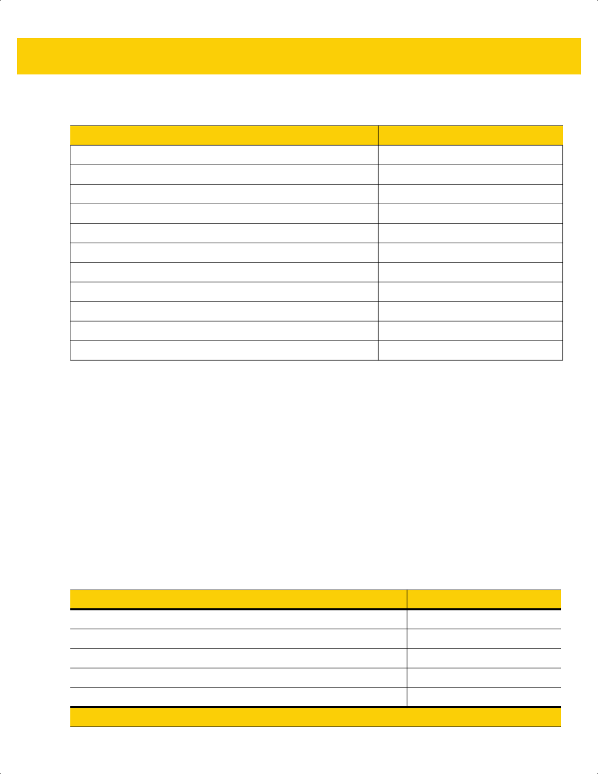
8 - 18 DS2278 Digital Scanner Product Reference Guide
Transmit Data Formatting
ARINC Format
Data is transmitted in the following format: <STX><DID><DOC><BID><DATA><ETX><CRC>
Where:
<STX> - 0x02
<DID> - 0xB1 (DTYP and DNUM)
<DOC> - 0x30 (Document Identifier)
<BID> - Bar code Identifier (Table 8-3)
<DATA> - Bar code decode data
<ETX> - 0x03
<CRC> - CRC-16
Table 8-2 Parameter Default for Airport Device Types
Parameter ARINC Defaults
IATA 2 of 5 (D 2 of 5) Enabled
Parameter Scanning Disabled
IATA 2 of 5 (D 2 of 5) lengths 6 to 55
I 2 of 5 Enabled
I 2 of 5 lengths 4 to 56
Micro PDF N/R
PDF417 Enabled
Code39 Enabled
Code128 Enabled
Triggered Same Symbol Timeout Enabled
Transmit Code ID Disabled
Table 8-3 ARINC Bar Code Identifier
Bar Code Type ASCII Value
Interleaved 2 of 5 1
Industrial 2 of 5 (D 2 of 5) 2
Code 39 3
Code 128 5
Code 39 with check digit
*
8
* Note: Bar code types with check digits are currently not supported on the scanner for ARINC.
ds2278-prg-en.book Page 18
USB Interface 8 - 19
TGCS (IBM) USB Direct I/O Beep
The host can send a direct I/O beep request to the scanner. If you select Ignore Direct I/O Beep, the scanner does
not sound beeps on this command. All directives are still acknowledged to the USB host as if they were processed.
Industrial 2 of 5 with check digit
*
9
Interleaved 2 of 5 with check digit
*
0
2D Data Matrix 4
2D QR 7
2D PDF 6
EAN 13 with check digit
*
A
2D Aztec 8
All others None
Table 8-3 ARINC Bar Code Identifier (Continued)
Bar Code Type ASCII Value
* Note: Bar code types with check digits are currently not supported on the scanner for ARINC.
*Honor Direct IO Beep
Ignore Direct IO Beep
ds2278-prg-en.book Page 19

8 - 20 DS2278 Digital Scanner Product Reference Guide
TGCS (IBM) USB Beep Directive
The host can send a beeper configuration request to the scanner. Scan Ignore Beep Directive to prevent the
scanner from processing the host request. All directives are still acknowledged to the USB host as if they were
processed.
TGCS (IBM) USB Bar Code Configuration Directive
The host can enable and disable code types. Scan Ignore Bar Code Configuration Directive to prevent the
scanner from processing the host request. All directives are still acknowledged to the USB host as if they were
processed.
Honor Beep Directive
*Ignore Beep Directive
Honor Bar Code Configuration Directive
*Ignore Bar Code Configuration Directive
ds2278-prg-en.book Page 20

USB Interface 8 - 21
TGCS (IBM) USB Specification Version
Select IBM Specification Level Version 0 (Original) to send the following code types as Unknown:
• Data Matrix
• GS1 Data Matrix
• QR Code
• GS1 QR
• MicroQR Code
• Aztec
Select IBM Specification Level Version 2.2 to send the code types with the appropriate IBM identifiers.
ASCII Character Sets for USB
See Appendix I, ASCII Character Sets for the following:
• ASCII Character Set (Table I-1 on page I-1)
• ALT Key Character Set (Table I-2 on page I-6)
• GUI Key Character Set (Table I-3 on page I-7)
• F Key Character Set (Table I-5 on page I-10).
IBM Specification Level Version 0 (Original)
*IBM Specification Level Version 2.2
ds2278-prg-en.book Page 21

8 - 22 DS2278 Digital Scanner Product Reference Guide
ds2278-prg-en.book Page 22

CHAPTER 9 SSI INTERFACE
Introduction
This chapter describes the system requirements of the Simple Serial Interface (SSI), which provides a
communications link between Zebra decoders (e.g., scan engines, slot scanners, hand-held scanners,
two-dimensional scanners, hands-free scanners, and RF base stations) and a serial host. It provides the means for
the host to control the decoder or scanner.
Communication
All communication between the scanner and host occurs over the hardware interface lines using the SSI protocol.
Refer to the Simple Serial Interface Programmer’s Guide, p/n 72E-40451-xx, for more information on SSI.
The host and the scanner exchange messages in packets. A packet is a collection of bytes framed by the proper
SSI protocol formatting bytes. The maximum number of bytes per packet that the SSI protocol allows for any
transaction is 257 (255 bytes + 2 byte checksum).
Depending on the configuration, the scanner can send decode data as ASCII data (unpacketed), or as part of a
larger message (packeted).
SSI performs the following functions for the host device:
• Maintains a bi-directional interface with the scanner
• Allows the host to send commands that control the scanner
• Passes data from the scanner to a host device in SSI packet format or straight decode message.
The SSI environment consists of a scanner, a serial cable which attaches to the host device, and if required, a
power supply.
SSI transmits all decode data including special formatting (e.g., AIM ID). Parameter settings can control the format
of the transmitted data.
The scanner can also send parameter information, product identification information, or event codes to the host.
All commands sent between the scanner and host must use the format described in the SSI Message Formats
section. SSI Transactions on page 9-3 describes the required sequence of messages in specific cases.
ds2278-prg-en.book Page 1

9 - 2 DS2278 Digital Scanner Product Reference Guide
Table 9-1 lists all the SSI opcodes the scanner supports. The host transmits opcodes designated type H. The
scanner (decoder) transmits type D opcodes, and either can transmit Host/Decoder (H/D) types.
For details of the SSI protocol, refer to the Simple Serial Interface Programmer's Guide.
Table 9-1 SSI Commands
Name Type Opcode Description
AIM_OFF H 0xC4 Deactivate aim pattern.
AIM_ON H 0xC5 Activate aim pattern.
BEEP H 0xE6 Sound the beeper.
CAPABILITIES_REPLY D 0xD4 Reply to CAPABILITIES_REQUEST; contains a list of the
capabilities and commands the decoder supports.
CAPABILITIES_REQUEST H 0xD3 Request capabilities report from the decoder.
CMD_ACK H/D 0xD0 Positive acknowledgment of received packet.
CMD_NAK H/D 0xD1 Negative acknowledgment of received packet.
DECODE_DATA D 0xF3 Decode data in SSI packet format.
EVENT D 0xF6 Event indicated by associated event code.
LED_OFF H 0xE8 De-activate LED output.
LED_ON H 0xE7 Activate LED output.
PARAM_DEFAULTS H 0xC8 Set parameter default values.
PARAM_REQUEST H 0xC7 Request values of certain parameters.
PARAM_SEND H/D 0xC6 Send parameter values.
REPLY_REVISION D 0xA4 Reply to REQUEST_REVISION, contains the decoder's
software/hardware configuration.
REQUEST_REVISION H 0xA3 Request the decoder's configuration.
SCAN_DISABLE H 0xEA Prevent the operator from scanning bar codes.
SCAN_ENABLE H 0xE9 Permit bar code scanning.
SLEEP H 0xEB Request to place the decoder into low power.
START_DECODE H 0xE4 Tell the decoder to attempt to decode a bar code.
STOP_DECODE H 0xE5 Tell the decoder to abort a decode attempt.
WAKEUP H N/A Wake the decoder from low power mode.
ds2278-prg-en.book Page 2

SSI Interface 9 - 3
SSI Transactions
General Data Transactions
ACK/NAK Handshaking
If you enable ACK/NAK handshaking (the default), all packeted messages must have a CMD_ACK or CMD_NAK
response, unless the command description states otherwise. Zebra recommends leaving this handshaking
enabled to provide feedback to the host. Raw decode data and WAKEUP do not use ACK/NAK handshaking since
they are not packeted data.
Following is an example of a problem which can occur if you disable ACK/NAK handshaking:
• The host sends a PARAM_SEND message to the scanner to change the baud rate from 9600 to 19200.
• The scanner cannot interpret the message.
• The scanner does not implement the change the host requested.
• The host assumes that the parameter change occurred and acts accordingly.
• Communication is lost because the change did not occur on both sides.
If you enable ACK/NAK handshaking, the following occurs:
• The host sends a PARAM_SEND message.
• The scanner cannot interpret the message.
• The scanner CMD_NAKs the message.
• The host resends the message.
• The scanner receives the message successfully, responds with CMD_ACK, and implements parameter
changes.
ds2278-prg-en.book Page 3
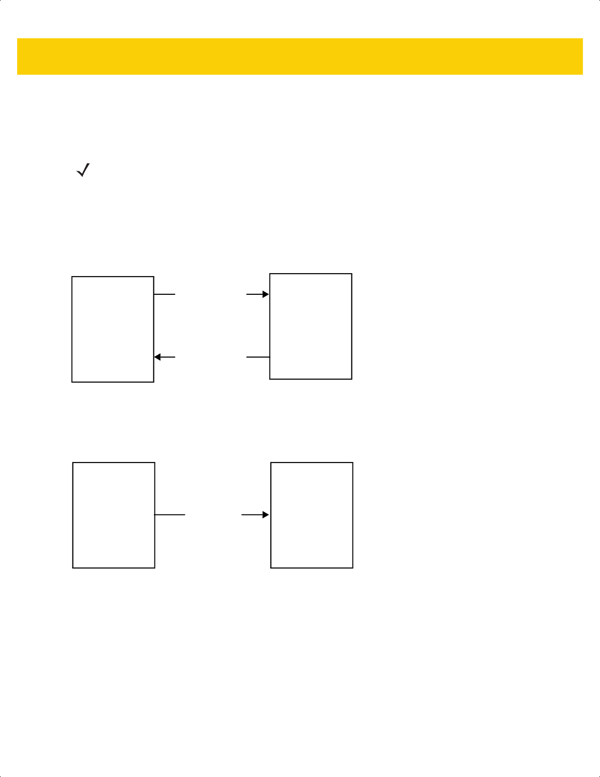
9 - 4 DS2278 Digital Scanner Product Reference Guide
Decoded Data Transmission
The Decode Data Packet Format parameter controls how decode data is sent to the host. Set this parameter to
send the data in a DECODE_DATA packet. Clear this parameter to transmit the data as raw ASCII data.
ACK/NAK Enabled and Packeted Data
The scanner sends a DECODE_DATA message after a successful decode. The scanner waits for a programmable
timeout for a CMD_ACK response. If it does not receive the response, the scanner tries to send two more times
before issuing a host transmission error. If the scanner receives a CMD_NAK from the host, it may attempt a retry
depending on the cause field of the CMD_NAK message.
ACK/NAK Enabled and Unpacketed ASCII Data
Even if ACK/NAK handshaking is enabled, no handshaking occurs because handshaking applies only to packeted
data. In this example the packeted_decode parameter is disabled.
NOTE When transmitting decode data as raw ASCII data, ACK/NAK handshaking does not apply regardless of
the state of the ACK/NAK handshaking parameter.
Decoder
Data is captured
by decoder
Host
(1)
DECODE_DATA
(2)
CMD_ACK
message sent
Decoder
Data is captured
by decoder
Host
ASCII data
ds2278-prg-en.book Page 4
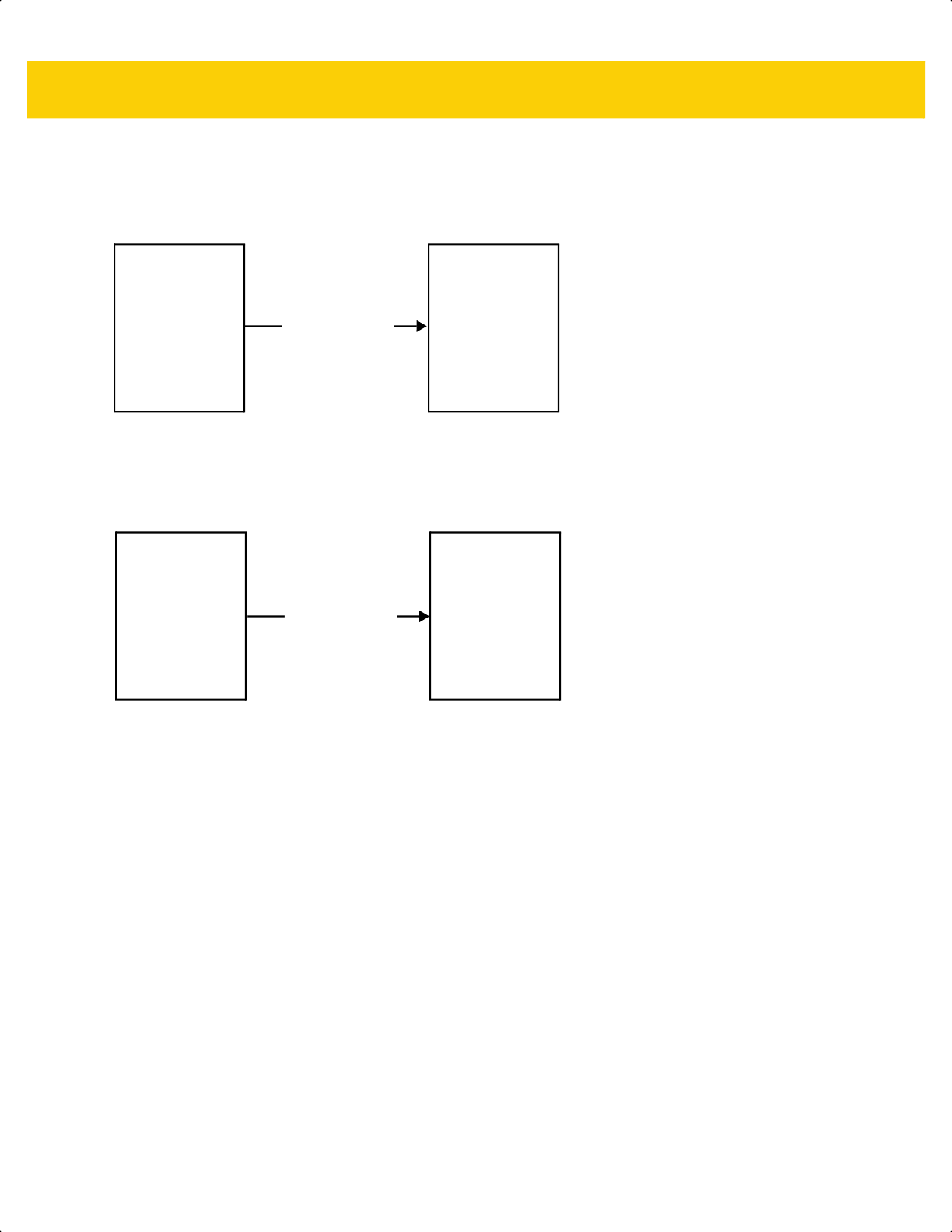
SSI Interface 9 - 5
ACK/NAK Disabled and Packeted DECODE_DATA
In this example ACK/NAK does not occur even though packeted_decode is enabled because the ACK/NAK
handshaking parameter is disabled.
ACK/NAK Disabled and Unpacketed ASCII Data
The decoder sends captured data to the host.
Decoder
Data is captured
by decoder
Host
(1)
DECODE_DATA
message sent
Decoder
Data is captured
by decoder
Host
(1)
ASCII data sent
ds2278-prg-en.book Page 5

9 - 6 DS2278 Digital Scanner Product Reference Guide
Communication Summary
RTS/CTS Lines
All communication must use RTS/CTS handshaking as described in the Simple Serial Interface Programmer’s
Guide, p/n 72E-40451-xx. If bypassing hardware handshaking, the host must send the WAKEUP command before
all other communication or the first byte of a message can be lost during the scanner wakeup sequence. Zebra
recommends not bypassing RTS/CTS hardware handshaking.
ACK/NAK Option
ACK/NAK handshaking is enabled by default and Zebra recommends leaving it enabled. Disabling this can cause
communication problems, as handshaking is the only acknowledgment that a message was received correctly.
ACK/NAK is not used with unpacketed decode data regardless of whether it is enabled.
Number of Data Bits
All communication with the scanner must use 8-bit data.
Serial Response Timeout
The Host Serial Response Timeout parameter determines how long to wait for a handshaking response before
trying again or aborting further attempts. Set the same value for both the host and scanner.
Retries
The host resends data twice after the initial send if the scanner does not respond with an ACK or NAK (if ACK/NAK
handshaking is enabled), or response data (e.g., PARAM_SEND, REPLY_REVISION). If the scanner replies with a
NAK RESEND, the host resends the data. All resent messages must have the resend bit set in the Status byte.
The scanner resends data two times after the initial send if the host fails to reply with an ACK or NAK (if ACK/NAK
handshaking is enabled).
Baud Rate, Stop Bits, Parity, Response Timeout, ACK/NAK Handshaking
If you use PARAM_SEND to change these serial parameters, the ACK response to the PARAM_SEND uses the
previous values for these parameters. The new values then take effect for the next transaction.
Errors
The scanner issues a communication error when:
• The CTS line is asserted when the scanner tries to transmit, and is still asserted on each of two successive
retries
• The scanner does not receive an ACK or NAK after initial transmit and two resends.
NOTE You can temporarily change the Host Serial Response Timeout when the host takes longer to process an
ACK or longer data string. Zebra does not recommend frequent permanent changes due to limited write
cycles of non-volatile memory.
ds2278-prg-en.book Page 6
SSI Interface 9 - 7
SSI Communication Notes
• When not using hardware handshaking, space messages sufficiently apart. The host must not communicate
with the scanner if the scanner is transmitting.
• When using hardware handshaking, frame each message properly with handshaking signals. Do not try to
send two commands within the same handshaking frame.
• There is a permanent/temporary bit in the PARAM_SEND message. Removing power from the scanner
discards temporary changes. Permanent changes are written to non-volatile memory. Frequent changes
shorten the life of the non-volatile memory.
Using Time Delay to Low Power Mode with SSI
Time Delay to Low Power Mode on page 5-12 provides options to select a general time delay. To program a more
specific delay value, use an SSI command according to Table 9-2.
Table 9-2 Values for Selecting Time Delay to Low Power
Value Timeout Value Timeout Value Timeout Value Timeout
0x00 15 Min 0x10 1 Sec 0x20 1 Min 0x30 1 Hour
0x01 30 Min 0x11 1 Sec 0x21 1 Min 0x31 1 Hour
0x02 60 Min 0x12 2 Sec 0x22 2 Min 0x32 2 Hours
0x03 90 Min 0x13 3 Sec 0x23 3 Min 0x33 3 Hours
N/A N/A 0x14 4 Sec 0x24 4 Min 0x34 4 Hours
N/A N/A 0x15 5 Sec 0x25 5 Min 0x35 5 Hours
N/A N/A 0x16 6 Sec 0x26 6 Min 0x36 6 Hours
N/A N/A 0x17 7 Sec 0x27 7 Min 0x37 7 Hours
N/A N/A 0x18 8 Sec 0x28 8 Min 0x38 8 Hours
N/A N/A 0x19 9 Sec 0x29 9 Min 0x39 9 Hours
N/A N/A 0x1A 10 Sec 0x2A 10 Min 0x3A 10 Hours
N/A N/A 0x1B 15 Sec 0x2B 15 Min 0x3B 15 Hours
N/A N/A 0x1C 20 Sec 0x2C 20 Min 0x3C 20 Hours
N/A N/A 0x1D 30 Sec 0x2D 30 Min 0x3D 30 Hours
N/A N/A 0x1E 45 Sec 0x2E 45 Min 0x3E 45 Hours
N/A N/A 0x1F 60 Sec 0x2F 60 Min 0x3F 60 Hours
CAUTION With hardware handshaking disabled, the scanner wakes from low power mode upon receiving a
character. However, the scanner does not process this character or any others it receives during the
7 ms period following wakeup. Wait at least 7 ms after wakeup to send valid characters.
ds2278-prg-en.book Page 7
9 - 8 DS2278 Digital Scanner Product Reference Guide
Encapsulation of RSM Commands/Responses over SSI
The SSI protocol allows the host to send a command that is variable in length up to 255 bytes. Although there is a
provision in the protocol to multi-packet commands from the host, the scanner does not support this. The host must
fragment packets using the provisions in the RSM protocol.
Command Structure
The expected positive response is SSI_MGMT_COMMAND which can be a multi-packet response. Devices that
do not support this command respond with the standard SSI_NAK.
Response Structure
Byte 7 6 5 4 3 2 1 0
0 Length (not including the checksum)
1 SSI_MGMT_COMMAND (0x80)
2 Message Source (4 - Host)
3 Reserved (0) Reserved (0) Reserved (0) Cont'd packet Retransmit
4 Payload data (see the following example)
...
Length -1
Length 2's complement checksum (MSB)
Length +1 2's complement checksum (LSB)
Byte 7 6 5 4 3 2 1 0
0 Length (not including the checksum)
1 SSI_MGMT_COMMAND (0x80)
2 Message Source (0 - Decoder)
3 Reserved (0) Reserved (0) Reserved (0) Cont'd packet Retransmit
4 Payload data (see the following example)
...
Length -1
Length 2's complement checksum (MSB)
Length +1 2's complement checksum (LSB)
ds2278-prg-en.book Page 8

SSI Interface 9 - 9
Example Transaction
The following example illustrates how to retrieve diagnostic information (Diagnostic Testing and Reporting
(Attribute #10061) decimal) from the scanner using encapsulation of RSM commands over SSI. Before sending an
RSM command, the host must send the RSM Get Packet Size command to query the packet size supported by the
device.
Command from Host to Query Packet Size Supported by Device
0A 80 04 00 00 06 20 00 FF FF FD 4E
Where:
• 0A 80 04 00 is encapsulation of RSM commands over SSI command header
• 00 06 20 00 FF FF is RSM Get Packet Size command
• FD 4E is SSI command checksum
Response from Device with Packet Size Information
0C 80 00 00 00 08 20 00 00 F0 00 F0 FD 6C
Where:
• 0C 80 00 00 is encapsulation of RSM command over SSI command header
• 00 08 20 00 00 F0 00 F0 is RSM Get Packet Size response
• FD 6C is SSI response checksum
Command from Host to Retrieve Diagnostic Information
0C 80 04 00 00 08 02 00 27 4D 42 00 FE B0
Where:
• 0C 80 04 00 is encapsulation of RSM commands over SSI command header
• 00 08 02 00 27 4D 42 00 is attribute Get command requesting attribute 10061 decimal
• FE B0 is SSI command checksum
Response from Device with Diagnostic Information
21 80 00 00 00 1D 02 00 27 4D 41 01 42 00 0E 00 00 00 00 01 03 02 03 03 03 04 03 05 03 06 03 FF FF FC 15
Where:
• 21 80 00 00 00 1D 02 00 27 4D 41 01 42 00 0E 00 00 is encapsulation of RSM responses over SSI
command header
• 00 00 01 03 02 03 03 03 04 03 05 03 06 03 is attribute Get response which includes diagnostic report value
• FF FF is attribute Get response, packet termination
• FC 15 is SSI response checksum
ds2278-prg-en.book Page 9

9 - 10 DS2278 Digital Scanner Product Reference Guide
Setting Parameters
This section describes how to set up the scanner with an SSI host. When using SSI, program the scanner via bar
code menu or SSI hosts commands.
The scanner ships with the settings shown in Table 9-3 on page 9-11 (also see Appendix A, Standard Default
Parameters for all defaults). If the default values suit requirements, programming is not necessary.
To set feature values, scan a single bar code or a short bar code sequence. The settings are stored in non-volatile
memory and are preserved even when the scanner powers down.
To return all features to default values, scan Set Factory Defaults on page 5-5. Throughout the programming bar
code menus, asterisks (
*) indicate default values.
Scanning Sequence Examples
In most cases scanning one bar code sets the parameter value. For example, to set the baud rate to 19,200, scan
the Baud Rate 19,200 bar code under Baud Rate on page 9-12. The scanner issues a fast warble beep and the
LED turns green, signifying a successful parameter entry.
Other parameters require scanning several bar codes. See the parameter descriptions for this procedure.
Errors While Scanning
Unless otherwise specified, to correct an error during a scanning sequence, just re-scan the correct parameter.
NOTE Most computer monitors allow scanning bar codes directly on the screen. When scanning from the screen,
be sure to set the document magnification to a level where you can see the bar code clearly, and bars
and/or spaces do not merge.
*Enable Parameter
(1)
Feature/option
* Indicates default
Option value
ds2278-prg-en.book Page 10
SSI Interface 9 - 11
Simple Serial Interface Parameter Defaults
Table 9-1 lists defaults for SSI host parameters. Change these values in one of two ways:
• Scan the appropriate bar codes in this chapter. The new value replaces the standard default value in
memory. To recall default parameter values, see Default Parameters on page 5-5.
• Download data through the device’s serial port using SSI. Hexadecimal parameter numbers appear in this
chapter below the parameter title, and option values appear in parenthesis beneath the accompanying bar
codes. Refer to the Simple Serial Interface (SSI) Programmer’s Guide for detailed instructions for changing
parameters using this method.
NOTE See Appendix A, Standard Default Parameters for all user preference, host, symbology, and
miscellaneous default parameters.
Table 9-3 SSI Interface Default Table
Parameter
Parameter
Number
SSI Number Default
Page
Number
SSI Host Parameters
Select SSI Host N/A N/A N/A
9-12
Baud Rate 156 9Ch 9600
9-12
Parity 158 9Eh None
9-14
Check Parity 151 97h Disable
9-15
Stop Bits 157 9Dh 1
9-15
Software Handshaking 159 9Fh ACK/NAK
9-16
Host RTS Line State 154 9Ah Low
9-17
Decode Data Packet Format 238 EEh Send Raw Decode Data
9-17
Host Serial Response Timeout 155 9Bh 2 Seconds
9-18
Host Character Timeout 239 EFh 200 msec
9-19
Multipacket Option 334 F0h 4Eh Option 1
9-20
Interpacket Delay 335 F0h 4Fh 0 msec
9-21
Event Reporting
Decode Event 256 F0h 00h Disable
9-22
Boot Up Event 258 F0h 02h Disable
9-23
Parameter Event 259 F0h 03h Disable
9-23
NOTE SSI interprets Prefix, Suffix1, and Suffix2 values listed in Table I-1 on page I-1 differently than other
interfaces. SSI does not recognize key categories, only the 3-digit decimal value. The default value of
7013 is interpreted as CR only.
ds2278-prg-en.book Page 11

9 - 12 DS2278 Digital Scanner Product Reference Guide
SSI Host Parameters
Select SSI Host
To select SSI as the host interface, scan the following bar code.
Baud Rate
Parameter # 156
SSI # 9Ch
Baud rate is the number of bits of data transmitted per second. Scan one of the following bar codes to set the
scanner's baud rate to match the baud rate setting of the host device. Otherwise, data may not reach the host
device or may reach it in distorted form.
SSI Host
*Baud Rate 9600
(6)
Baud Rate 19,200
(7)
Baud Rate 38,400
(8)
Baud Rate 57,600
(10)
ds2278-prg-en.book Page 12

SSI Interface 9 - 13
Baud Rate (continued)
Baud Rate 115,200
(11)
Baud Rate 230,400
(13)
Baud Rate 460,800
(14)
Baud Rate 921,600
(15)
ds2278-prg-en.book Page 13

9 - 14 DS2278 Digital Scanner Product Reference Guide
Parity
Parameter # 158
SSI # 9Eh
A parity check bit is the most significant bit of each ASCII coded character. Scan one of the following bar codes to
select the parity type according to host device requirements:
• Odd - This sets the parity bit value to 0 or 1, based on data, to ensure that the coded character contains an
odd number of 1 bits.
• Even - This sets the parity bit value to 0 or 1, based on data, to ensure that the coded character contains an
even number of 1 bits.
• None - No parity bit is required.
Odd
(2)
Even
(1)
*None
(0)
ds2278-prg-en.book Page 14

SSI Interface 9 - 15
Check Parity
Parameter # 151
SSI # 97h
Scan one of the following bar codes to select whether to check the parity of received characters. See Parity to
select the type of parity.
Stop Bits
Parameter # 157
SSI # 9Dh
The stop bit(s) at the end of each transmitted character marks the end of transmission of one character and
prepares the receiving device for the next character in the serial data stream. Scan one of the following bar codes
to set the number of stop bits (one or two) based on the number the receiving host can accommodate.
*Do Not Check Parity
(0)
Check Parity
(1)
*1 Stop Bit
(1)
2 Stop Bits
(2)
ds2278-prg-en.book Page 15

9 - 16 DS2278 Digital Scanner Product Reference Guide
Software Handshaking
Parameter # 159
SSI # 9Fh
This parameter offers control of data transmission in addition to the control hardware handshaking offers.
Hardware handshaking is always enabled; you cannot disable it.
Options:
• Disable ACK/NAK Handshaking - The scanner neither generates nor expects ACK/NAK handshaking
packets.
• Enable ACK/NAK Handshaking - After transmitting data, the scanner expects either an ACK or NAK
response from the host. The scanner also ACKs or NAKs messages from the host.
The scanner waits up to the programmable Host Serial Response Timeout to receive an ACK or NAK. If the
scanner does not get a response in this time, it resends its data up to two times before discarding the data
and declaring a transmission error.
Disable ACK/NAK
(0)
*Enable ACK/NAK
(1)
ds2278-prg-en.book Page 16

SSI Interface 9 - 17
Host RTS Line State
Parameter # 154
SSI # 9Ah
Scan one of the following bar codes to set the expected idle state of the Serial Host RTS line.
The SSI interface is used with host applications which also implement the SSI protocol. However, you can use the
scanner in a "scan-and-transmit" mode to communicate with any standard serial communication software on a host
PC (see Decode Data Packet Format on page 9-17). If transmission errors occur in this mode, the host PC may be
asserting hardware handshaking lines which interfere with the SSI protocol. Scan the High bar code to address
this problem.
Decode Data Packet Format
Parameter # 238
SSI # EEh
Scan one of the following bar codes to select whether to transmit decoded data in raw format (unpacketed), or with
the packet format defined by the serial protocol.
Selecting the raw format disables ACK/NAK handshaking for decode data.
*Low
(0)
High
(1)
*Send Raw Decode Data
(0)
Send Packeted Decode Data
(1)
ds2278-prg-en.book Page 17
9 - 18 DS2278 Digital Scanner Product Reference Guide
Host Serial Response Timeout
Parameter # 155
SSI # 9Bh
Scan one of the following bar codes to specify how long the scanner waits for an ACK or NAK before resending.
Also, if the scanner wants to send, and the host has already been granted permission to send, the scanner waits
for the designated timeout before declaring an error.
NOTE Other values are available via SSI command.
*Low - 2 Seconds
(20)
Medium - 5 Seconds
(50)
High - 7.5 Seconds
(75)
Maximum - 9.9 Seconds
(99)
ds2278-prg-en.book Page 18
SSI Interface 9 - 19
Host Character Timeout
Parameter # 239
SSI # EFh
Scan one of the following bar codes to specify the maximum time the scanner waits between characters
transmitted by the host before discarding the received data and declaring an error.
NOTE Other values are available via SSI command.
*Low - 200 msec
(20)
Medium - 500 msec
(50)
High - 750 msec
(75)
Maximum - 990 msec
(99)
ds2278-prg-en.book Page 19

9 - 20 DS2278 Digital Scanner Product Reference Guide
Multipacket Option
Parameter # 334
SSI # F0h 4Eh
Scan one of the following bar codes to control ACK/NAK handshaking for multi-packet transmissions:
• Multi-Packet Option 1 - The host sends an ACK/NAK for each data packet during a multi-packet
transmission.
• Multi-Packet Option 2 - The scanner sends data packets continuously, with no ACK/NAK handshaking to
pace the transmission. The host, if overrun, can use hardware handshaking to temporarily delay scanner
transmissions. At the end of transmission, the scanner waits for a CMD_ACK or CMD_NAK.
• Multi-Packet Option 3 - This is the same as option 2 with the addition of a programmable interpacket delay.
See Interpacket Delay on page 9-21 to set this delay.
*Multipacket Option 1
(0)
Multipacket Option 2
(1)
Multipacket Option 3
(2)
ds2278-prg-en.book Page 20
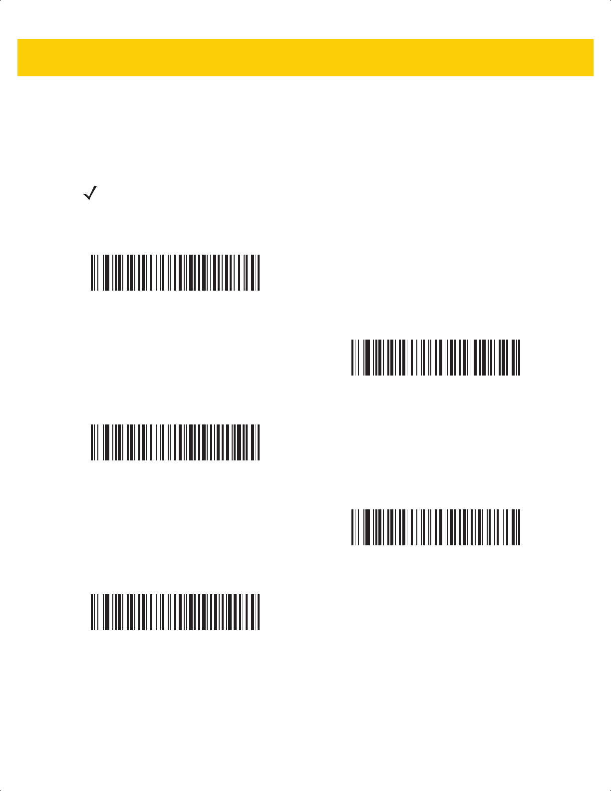
SSI Interface 9 - 21
Interpacket Delay
Parameter # 335
SSI # F0h 4Fh
Scan one of the following bar codes to specify the interpacket delay if you selected Multipacket Option 3.
NOTE Other values are available via SSI command.
*Minimum - 0 msec
(0)
Low - 25 msec
(25)
Medium - 50 msec
(50)
High - 75 msec
(75)
Maximum - 99 msec
(99)
ds2278-prg-en.book Page 21
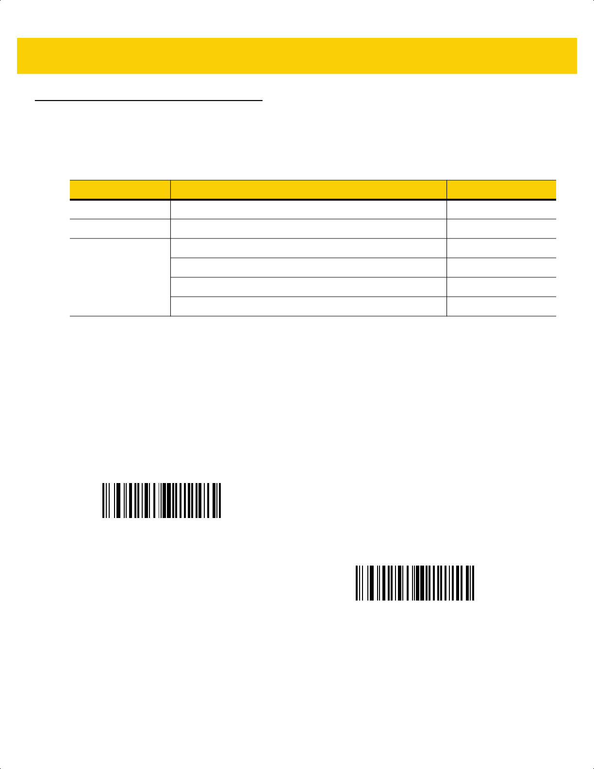
9 - 22 DS2278 Digital Scanner Product Reference Guide
Event Reporting
The host can request the scanner to provide certain information (events) relative to scanner behavior. Scan the
following bar codes to enable or disable the events listed in Table 9-4 and on the following pages.
Decode Event
Parameter # 256
SSI # F0h 00h
Scan one of the following bar codes to enable or disable Decode Event.
• Enable Decode Event - The scanner generates a message to the host upon a successful bar code decode.
• Disable Decode Event - No notification is sent.
Table 9-4 Event Codes
Event Class Event Code Reported
Decode Event Non-parameter decode 0x01
Boot Up Event System power-up 0x03
Parameter Event Parameter entry error 0x07
Parameter stored 0x08
Defaults set (and parameter event is enabled by default) 0x0A
Number expected 0x0F
Enable Decode Event
(1)
*Disable Decode Event
(0)
ds2278-prg-en.book Page 22

SSI Interface 9 - 23
Boot Up Event
Parameter # 258
SSI # F0h 02h
Scan one of the following bar codes to enable or disable Boot Up Event:
• Enable Boot Up Event - The scanner generates a message to the host whenever power is applied.
• Disable Boot Up Event - No notification is sent.
Parameter Event
Parameter # 259
SSI # F0h 03h
Scan one of the following bar codes to enable or disable Parameter Event:
• Enable Parameter Event - The scanner generates a message to the host when one of the events specified
in Table 9-4 on page 9-22 occurs.
• Disable Parameter Event - No notification is sent.
Enable Boot Up Event
(1)
*Disable Boot Up Event
(0)
Enable Parameter Event
(1)
*Disable Parameter Event
(0)
ds2278-prg-en.book Page 23

9 - 24 DS2278 Digital Scanner Product Reference Guide
ds2278-prg-en.book Page 24

CHAPTER 10 RS-232 INTERFACE
Introduction
This chapter describes how to set up the cradle with an RS-232 host. The cradle can use the RS-232 interface to
connect to point-of-sale devices, host computers, or other devices with an available RS-232 port (e.g., com port).
The scanner ships with the settings shown in Table 10-1 on page 10-3 (also see Appendix A, Standard Default
Parameters for all defaults). If the default values suit requirements, programming is not necessary.
If your host does not appear in Table 10-2, refer to the documentation for the host device to set communication
parameters to match the host.
Setting Parameters
To set feature values, scan a single bar code or a short bar code sequence. The settings are stored in non-volatile
memory and are preserved even when the scanner powers down.
To return all features to default values, scan Set Factory Defaults on page 5-5. Throughout the programming bar
code menus, asterisks (
*) indicate default values.
NOTE The scanner uses TTL RS-232 signal levels, which interface with most system architectures. For system
architectures requiring RS-232C signal levels, Zebra offers different cables providing TTL-to-RS-232C
conversion. Contact the Zebra Support & Downloads website for more information.
NOTE Most computer monitors allow scanning bar codes directly on the screen. When scanning from the screen,
be sure to set the document magnification to a level where you can see the bar code clearly, and bars
and/or spaces do not merge.
*Enable Parameter
Feature/option
* Indicates default
ds2278-prg-en.book Page 1
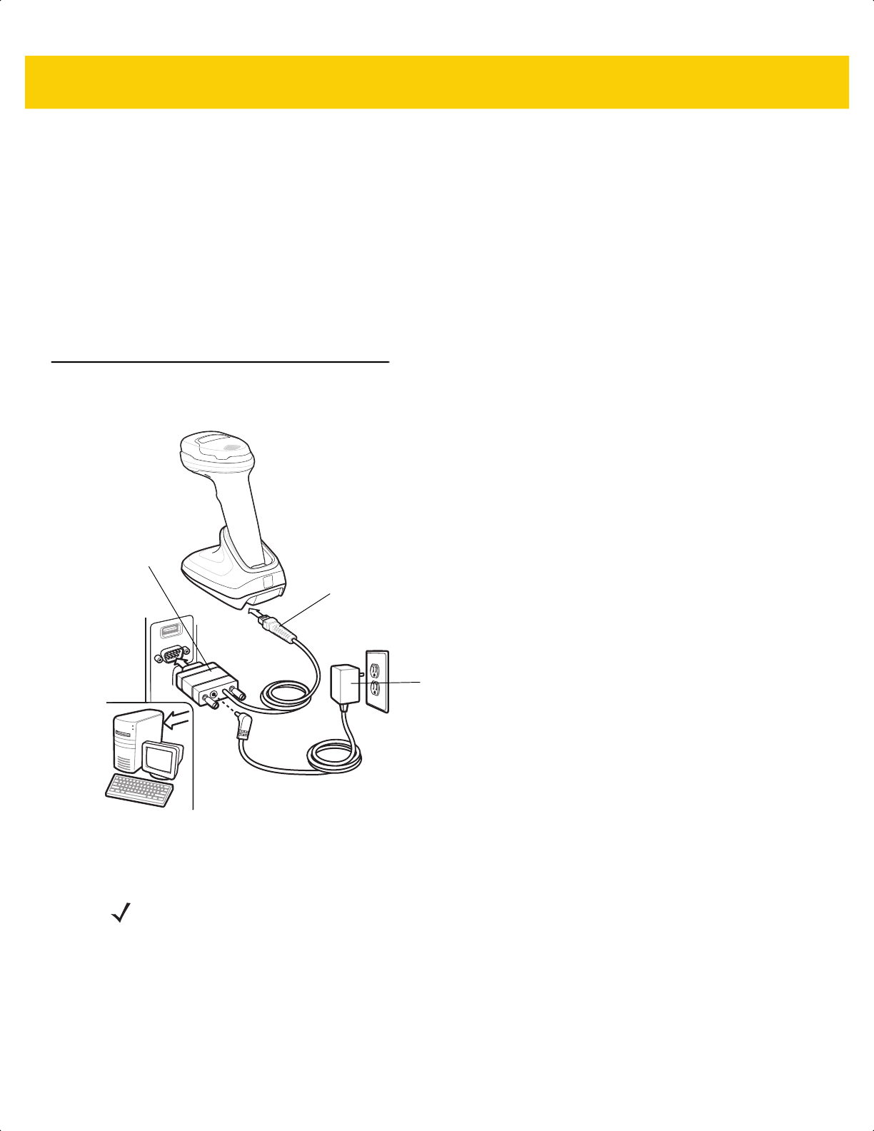
10 - 2 DS2278 Digital Scanner Product Reference Guide
Scanning Sequence Examples
In most cases scanning one bar code sets the parameter value. For example, to set the baud rate to 19,200, scan
the Baud Rate 19,200 bar code under Baud Rate on page 10-8. The scanner issues a fast warble beep and the
LED turns green, signifying a successful parameter entry.
Other parameters require scanning several bar codes. See the parameter descriptions for this procedure.
Errors While Scanning
Unless otherwise specified, to correct an error during a scanning sequence, just re-scan the correct parameter.
Connecting an RS-232 Interface
Connect the scanner directly to the host computer.
Figure 10-1 RS-232 Connection
1. Attach the modular connector of the RS-232 interface cable to the cable interface port on the cradle.
2. Connect the other end of the RS-232 interface cable to the serial port on the host.
3. If required, connect the power supply to the serial connector end of the RS-232 interface cable. Plug the power
supply into an appropriate outlet.
Serial port
connector
to host
Interface cable
Power supply
NOTE Interface cables vary depending on configuration. The connectors can be different than those illustrated in
Figure 10-1, but the steps to connect the scanner are the same.
ds2278-prg-en.book Page 2

RS-232 Interface 10 - 3
4. The scanner automatically detects the host interface type and uses the default setting. If the default (*) does
not meet your requirements, select another RS-232 host type by scanning the appropriate bar code from
RS-232 Host Types on page 10-6.
5. To modify any other parameter options, scan the appropriate bar codes in this chapter.
If problems occur with the system, see Troubleshooting on page 4-3.
RS-232 Parameter Defaults
Table 10-1 lists defaults for RS-232 host parameters. Change these values in one of two ways:
•
Scan the appropriate bar codes in this chapter. The new value replaces the standard default value in
memory. To recall default parameter values, see Default Parameters on page 5-5.
•
Configure the scanner using the 123Scan
configuration program. See Chapter 2, 123Scan and Software
Tools.
NOTE See Appendix A, Standard Default Parameters for all user preference, host, symbology, and
miscellaneous default parameters.
Table 10-1 RS-232 Interface Parameter Defaults
Parameter Default
Page
Number
RS-232 Host Parameters
RS-232 Host Types Standard
10-6
Baud Rate 9600
10-8
Parity None
10-9
Stop Bits 1 Stop Bit
10-9
Data Bits 8-bit
10-10
Check Receive Errors Enable
10-10
Hardware Handshaking None
10-11
Software Handshaking None
10-13
Host Serial Response Timeout 2 Sec
10-15
RTS Line State Low RTS
10-16
Beep on <BEL> Disable
10-16
Intercharacter Delay 0 msec
10-17
Nixdorf Beep/LED Options Normal Operation
10-18
Bar Codes with Unknown Characters Send Bar Code With Unknown
Characters
10-18
ds2278-prg-en.book Page 3

10 - 4 DS2278 Digital Scanner Product Reference Guide
RS-232 Host Parameters
Various RS-232 hosts use their own parameter default settings. Selecting standard, ICL, Fujitsu, Wincor-Nixdorf
Mode A, Wincor-Nixdorf Mode B, OPOS/JPOS, Olivetti, Omron, or Common Use Terminal Equipment
(CUTE-LP/LG bar code readers) sets the defaults listed in Table 10-2.
Table 10-2 Terminal Specific RS-232
Parameter ICL Fujitsu
Wincor-
Nixdorf
Mode A
Wincor-
Nixdorf Mode
B/OPOS/JPOS
Olivetti Omron CUTE
Transmit Code ID Yes Yes Yes Yes Yes Yes Yes
Data Transmission
Format
Data/Suffix Data/Suffix Data/Suffix Data/Suffix Prefix/Data/
Suffix
Data/Suffix Prefix/Data/
Suffix
Suffix CR (1013) CR (1013) CR (1013) CR (1013) ETX (1002) CR (1013) CR (1013)
ETX (1003)
Baud Rate 9600 9600 9600 9600 9600 9600 9600
Parity Even None Odd Odd Even None Even
Hardware
Handshaking
RTS/CTS
Option 3
None RTS/CTS
Option 3
RTS/CTS
Option 3
None None None
Software
Handshaking
None None None None ACK/NAK None None
Serial Response
Timeout
9.9 Sec. 2 Sec. None None 9.9 Sec. 9.9 Sec. 9.9 Sec.
Stop Bit Select One One One One One One One
ASCII Format 8-Bit 8-Bit 8-Bit 8-Bit 7-Bit 8-Bit 7-Bit
Beep On <BEL> Disable Disable Disable Disable Disable Disable Disable
RTS Line State High Low Low Low = No data to
send
Low High High
Prefix None None None None STX (1003) None STX (1002)
In the Wincor-Nixdorf Mode A/B, if CTS is low, scanning is disabled. When CTS is high, scanning is enabled.
If you scan Wincor-Nixdorf RS-232 Mode A/B without connecting the scanner to the proper host, it may appear
unable to scan. If this happens, scan a different RS-232 host type within 5 seconds of cycling power to the
scanner.
The CUTE host disables all parameter scanning, including Set Defaults. If you inadvertently select CUTE, scan
*Enable Parameter Bar Code Scanning (1) on page 5-6, then change the host selection.
ds2278-prg-en.book Page 4

RS-232 Interface 10 - 5
RS-232 Host Parameters (continued)
Selecting ICL, Fujitsu, Wincor-Nixdorf Mode A, Wincor-Nixdorf Mode B, OPOS/JPOS, Olivetti, Omron, or
CUTE-LP/LG bar code readers transmits the code ID characters listed in Table 10-3. These code ID characters are
not programmable and are separate from the Transmit Code ID feature. Do not enable the Transmit Code ID
feature for these terminals.
Table 10-3 Terminal Specific Code ID Characters
Code Type ICL Fujitsu
Wincor-
Nixdorf
Mode A
Wincor-Nixdorf
Mode B/
OPOS/JPOS
Olivetti Omron CUTE
UPC-A A A A A A A A
UPC-E E E C C C E None
EAN-8/JAN-8 FF FF B B B FF None
EAN-13/JAN-13 F F A A A F A
Code 39 C <len> None M M M <len> C <len> 3
Code 39 Full ASCII None None M M None None 3
Codabar N <len> None N N N <len> N <len> None
Code 128 L <len> None K K K <len> L <len> 5
I 2 of 5 I <len> None I I I <len> I <len> 1
Code 93 None None L L L <len> None None
D 2 of 5 H <len> None H H H <len> H <len> 2
GS1-128 L <len> None P P P <len> L <len> 5
MSI None None O O O <len> None None
Bookland EAN F F A A A F None
Trioptic None None None None None None None
Code 11 None None None None None None None
IATA H<len> None H H H<len> H<len> 2
Code 32 None None None None None None None
GS1 DataBar
Variants
None None E E None None None
PDF417 None None Q Q None None 6
Data Matrix None None R R None None 4
GS1 Data Matrix None None W W None None None
QR Codes None None U U None None 7
GS1 QR None None X X None None None
ds2278-prg-en.book Page 5
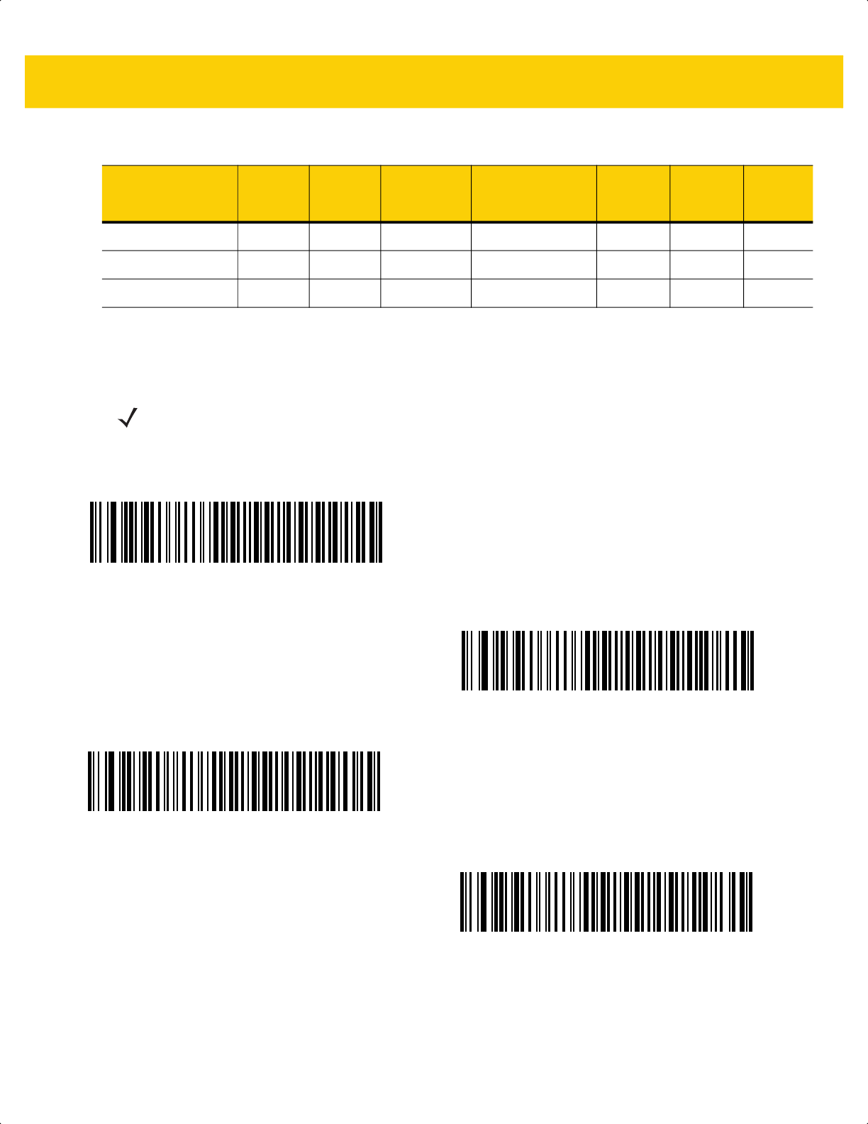
10 - 6 DS2278 Digital Scanner Product Reference Guide
RS-232 Host Types
To select an RS-232 host interface, scan one of the following bar codes.
1
Scanning Standard RS-232 activates the RS-232 driver, but does not change port settings (e.g., parity, data bits,
handshaking). Selecting another RS-232 host type bar code changes these settings.
Aztec/Aztec Rune None None V V None None 8
Maxicode None None T T None None None
MicroPDF None None S S None None 6
Table 10-3 Terminal Specific Code ID Characters (Continued)
Code Type ICL Fujitsu
Wincor-
Nixdorf
Mode A
Wincor-Nixdorf
Mode B/
OPOS/JPOS
Olivetti Omron CUTE
NOTE For a list of supported scanner functionality by communication protocol, see
Appendix J, Communication Protocol Functionality.
*Standard RS-232
1
ICL RS-232
Wincor-Nixdorf RS-232 Mode A
Wincor-Nixdorf RS-232 Mode B
ds2278-prg-en.book Page 6
RS-232 Interface 10 - 7
RS-232 Host Types (continued)
2
The CUTE host disables all parameter scanning, including Set Defaults. If you inadvertently select CUTE, scan
*Enable Parameter Bar Code Scanning (1) on page 5-6, and then change the host selection.
Olivetti ORS4500
Omron
OPOS/JPOS
Fujitsu RS-232
CUTE
2
ds2278-prg-en.book Page 7
10 - 8 DS2278 Digital Scanner Product Reference Guide
Baud Rate
Baud rate is the number of bits of data transmitted per second. Scan one of the following bar codes to set the
scanner's baud rate to match the baud rate setting of the host device. Otherwise, data may not reach the host
device or may reach it in distorted form.
NOTE The scanner does not support baud rates below 9600.
*Baud Rate 9600
Baud Rate 19,200
Baud Rate 38,400
Baud Rate 57,600
Baud Rate 115,200
ds2278-prg-en.book Page 8

RS-232 Interface 10 - 9
Parity
A parity check bit is the most significant bit of each ASCII coded character. Scan one of the following bar codes to
select the parity type according to host device requirements:
•
Odd - This sets the parity bit value to 0 or 1, based on data, to ensure that the coded character contains an
odd number of 1 bits.
•
Even - This sets the parity bit value to 0 or 1, based on data, to ensure that the coded character contains an
even number of 1 bits.
•
None - No parity bit is required.
Stop Bits
The stop bit(s) at the end of each transmitted character marks the end of transmission of one character and
prepares the receiving device for the next character in the serial data stream. Scan one of the following bar codes
to set the number of stop bits (one or two) based on the number the receiving host can accommodate.
Odd
Even
*None
*1 Stop Bit
2 Stop Bits
ds2278-prg-en.book Page 9

10 - 10DS2278 Digital Scanner Product Reference Guide
Data Bits
This parameter allows the scanner to interface with devices requiring a 7-bit or 8-bit ASCII protocol.
Check Receive Errors
Scan one of the following bar codes to set whether to check the parity, framing, and overrun of received characters.
The parity value of received characters is verified against the value set for Parity on page 10-9.
7-bit
*8-bit
*Check For Received Errors
Do Not Check For Received Errors
ds2278-prg-en.book Page 10

RS-232 Interface10 - 11
Hardware Handshaking
The data interface consists of an RS-232 port designed to operate either with or without the hardware handshaking
lines Request to Send (RTS) and Clear to Send (CTS).
If hardware handshaking and software handshaking are both enabled, hardware handshaking takes precedence.
Options:
•
None - This disables hardware handshaking and transmits scan data as it becomes available.
•
Standard RTS/CTS - This sets standard RTS/CTS hardware handshaking and transmits scanned data
according to the following sequence:
a. The scanner reads the CTS line for activity:
• If the CTS line is de-asserted, the scanner asserts the RTS line and waits up to Host Serial Response
Timeout on page 10-15 for the host to assert CTS, and then transmits data when asserted. If, after the
timeout, the CTS line is not asserted, the scanner sounds a transmit error and discards the data.
• If CTS is asserted, the scanner waits up to Host Serial Response Timeout for the host to de-assert
CTS. If after this timeout the CTS line is still asserted, the scanner sounds a transmit error and discards
the scanned data.
b. The scanner de-asserts RTS after sending the last character of data.
c. The host negates CTS. The scanner checks for a de-asserted CTS upon the next data transmission.
During data transmission, if CTS is deasserted for more than 50 ms between characters, the scanner sounds
a transmit error and discards the data. The data must be re-scanned.
•
RTS/CTS Option 1 - The scanner asserts RTS before transmitting and ignores the state of CTS. The
scanner de-asserts RTS when transmission completes.
•
RTS/CTS Option 2 - RTS is always high or low (user-programmed logic level). However, the scanner waits
for the host to assert CTS before transmitting data. If CTS is not asserted within the Host Serial Response
Timeout, the scanner sounds a transmit error and discards the data. During data transmission, if CTS is
de-asserted for more than 50 ms between characters, the scanner sounds a transmit error and discards the
data.
•
RTS/CTS Option 3 - This transmits scanned data according to the following sequence:
a. The scanner asserts RTS before data transmission, regardless of the state of CTS.
b. The scanner waits up to the Host Serial Response Timeout for the host to assert CTS, and then transmits
data when asserted. If, after the timeout, the CTS line is not asserted, the scanner sounds a transmit error
and discards the data.
c. The scanner de-asserts RTS after sending the last character of data.
d. The host negates CTS. The scanner checks for a de-asserted CTS upon the next data transmission.
During data transmission, if CTS is deasserted for more than 50 ms between characters, the scanner sounds
a transmit error and discards the data. The data must be re-scanned.
NOTE The DTR signal is jumpered to the active state.
ds2278-prg-en.book Page 11

10 - 12DS2278 Digital Scanner Product Reference Guide
Hardware Handshaking (continued)
*None
Standard RTS/CTS
RTS/CTS Option 1
RTS/CTS Option 2
RTS/CTS Option 3
ds2278-prg-en.book Page 12

RS-232 Interface10 - 13
Software Handshaking
This parameter offers control of data transmission in addition to, or instead of, that offered by hardware
handshaking. If software handshaking and hardware handshaking are both enabled, hardware handshaking takes
precedence.
Options:
•
None - This transmits data immediately. The scanner expects no response from the host.
•
ACK/NAK - After transmitting data, the scanner waits for an ACK or NAK response from the host. If it
receives a NAK, the scanner transmits the data again and waits for an ACK or NAK. After three unsuccessful
attempts to send data after receiving NAKs, the scanner sounds a transmit error and discards the data.
The scanner waits up to the programmable Host Serial Response Timeout to receive an ACK or NAK. If the
scanner does not get a response in this time, it sounds a transmit error and discards the data. There are no
reattempts.
•
ENQ - The scanner waits for an ENQ character from the host before transmitting data. If it does not receive
an ENQ within the Host Serial Response Timeout, the scanner sounds a transmit error and discards the
data. The host must transmit an ENQ character at least every Host Serial Response Timeout to prevent
transmission errors.
•
ACK/NAK with ENQ - This combines the two previous options. An additional ENQ is not required to
re-transmit data due to a NAK from the host.
•
XON/XOFF - An XOFF character stops data transmission until the scanner receives an XON character.
There are two situations for XON/XOFF:
• The scanner receives an XOFF before it has data to send. When the scanner has data, it waits up to the
Host Serial Response Timeout for an XON character before transmitting. If it does not receive the XON
within this time, the scanner sounds a transmit error and discards the data.
• The scanner receives an XOFF during data transmission and stops transmission after sending the current
byte. When the scanner receives an XON character, it sends the rest of the data. The scanner waits
indefinitely for the XON.
ds2278-prg-en.book Page 13

10 - 14DS2278 Digital Scanner Product Reference Guide
Software Handshaking (continued)
*None
ACK/NAK
ENQ
ACK/NAK with ENQ
XON/XOFF
ds2278-prg-en.book Page 14
RS-232 Interface10 - 15
Host Serial Response Timeout
Scan one of the following bar codes to specify how long the scanner waits for an ACK, NAK, or CTS before
determining that a transmission error occurred. This only applies when in one of the ACK/NAK software
handshaking modes, or RTS/CTS hardware handshaking mode.
*Minimum: 2 Seconds
Low: 2.5 Seconds
Medium: 5 Seconds
High: 7.5 Seconds
Maximum: 9.9 Seconds
ds2278-prg-en.book Page 15

10 - 16DS2278 Digital Scanner Product Reference Guide
RTS Line State
Scan one of the following bar codes to set the idle state of the serial host RTS line to Low RTS or High RTS.
Beep on <BEL>
Scan one of the following bar codes to set whether the scanner issues a beep when it detects a <BEL> character
on the RS-232 serial line. <BEL> indicates an illegal entry or other important event.
*Host: Low RTS
Host: High RTS
Beep On <BEL> Character
(Enable)
*Do Not Beep On <BEL> Character
(Disable)
ds2278-prg-en.book Page 16

RS-232 Interface10 - 17
Intercharacter Delay
Scan one of the following bar codes to specify the intercharacter delay inserted between character transmissions.
*Minimum: 0 msec
Low: 25 msec
Medium: 50 msec
High: 75 msec
Maximum: 99 msec
ds2278-prg-en.book Page 17
10 - 18DS2278 Digital Scanner Product Reference Guide
Nixdorf Beep/LED Options
If you selected Nixdorf Mode B, scan one of the following bar codes to indicate when the scanner beeps and turns
on its LED after a decode.
Bar Codes with Unknown Characters
Unknown characters are characters the host does not recognize. Scan Send Bar Codes With Unknown
Characters to send all bar code data except for unknown characters. The scanner issues no error beeps.
Scan Do Not Send Bar Codes With Unknown Characters to send bar code data up to the first unknown
character. The scanner issues an error beep.
ASCII Character Set for RS-232
See Appendix I, ASCII Character Sets for Prefix/Suffix values. The values in Table I-1 can be assigned as prefixes
or suffixes for ASCII character data transmission.
*Normal Operation
(Beep/LED Immediately After Decode)
Beep/LED After Transmission
Beep/LED After CTS Pulse
*Send Bar Codes With Unknown Characters
Do Not Send Bar Codes With Unknown Characters
ds2278-prg-en.book Page 18

CHAPTER 11 IBM 468X / 469X
INTERFACE
Introduction
This chapter describes how to set up the cradle with an IBM 468X/469X host.
The scanner ships with the settings shown in Table 11-1 on page 11-3 (also see Appendix A, Standard Default
Parameters for all defaults). If the default values suit requirements, programming is not necessary.
Setting Parameters
To set feature values, scan a single bar code or a short bar code sequence. The settings are stored in non-volatile
memory and are preserved even when the scanner powers down.
To return all features to default values, scan Set Factory Defaults on page 5-5. Throughout the programming bar
code menus, asterisks (*) indicate default values.
Scanning Sequence Examples
In most cases scanning one bar code sets the parameter value. For example, to select the Port 9B address, scan
the Hand-Held Scanner Emulation (Port 9B) bar code under Port Address on page 11-4. The scanner issues a
fast warble beep and the LED turns green, signifying a successful parameter entry.
Other parameters require scanning several bar codes. See the parameter descriptions for this procedure.
NOTE Most computer monitors allow scanning bar codes directly on the screen. When scanning from the screen,
be sure to set the document magnification to a level where you can see the bar code clearly, and bars
and/or spaces do not merge.
*Enable Parameter
Feature/option* Indicates default
ds2278-prg-en.book Page 1
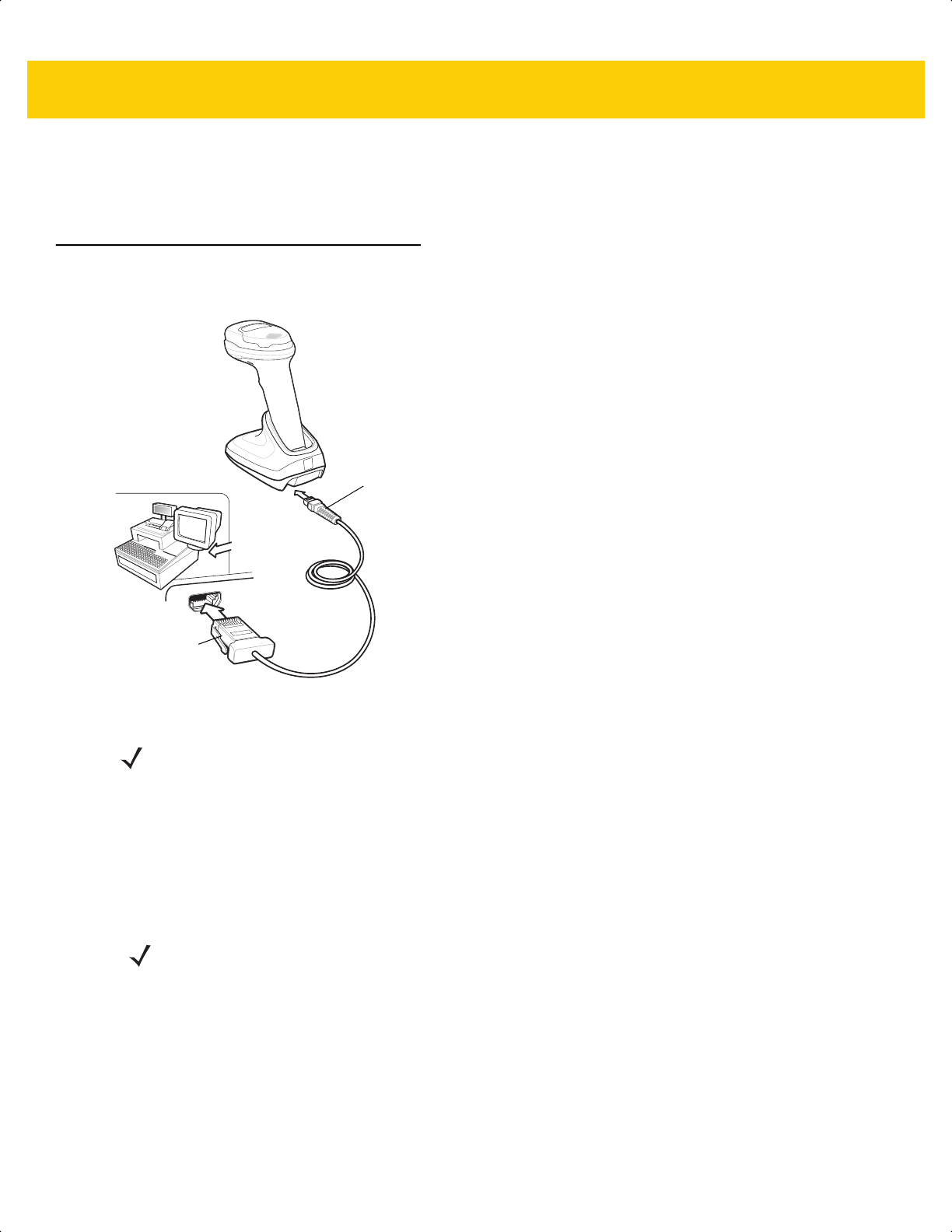
11 - 2 DS2278 Digital Scanner Product Reference Guide
Errors While Scanning
Unless otherwise specified, to correct an error during a scanning sequence, just re-scan the correct parameter.
Connecting an IBM 468X/469X Host
Connect the scanner directly to the host computer.
Figure 11-1 IBM Connection
1. Attach the modular connector of the IBM 46XX interface cable to the cable interface port on the cradle.
2. Connect the other end of the IBM 46XX interface cable to the appropriate port on the host (typically Port 9).
3. The scanner automatically detects the host interface type, but there is no default setting. Scan the appropriate
bar code from Port Address on page 11-4 to select the port address.
4. To modify any other parameter options, scan the appropriate bar codes in this chapter.
If problems occur with the system, see Troubleshooting on page 4-3.
Host port
connector
Interface cable
NOTE Interface cables vary depending on configuration. The connectors can be different than those illustrated in
Figure 11-1, but the steps to connect the scanner are the same.
NOTE The only required configuration is the port address. The IBM system typically controls other scanner
parameters.
ds2278-prg-en.book Page 2

IBM 468X / 469X Interface 11 - 3
IBM Parameter Defaults
Table 11-1 lists defaults for IBM host parameters. Change these values in one of two ways:
• Scan the appropriate bar codes in this chapter. The new value replaces the standard default value in
memory. To recall default parameter values, see Default Parameters on page 5-5.
• Configure the scanner using the 123Scan
configuration program. See Chapter 2, 123Scan and Software
Tools.
NOTE See Appendix A, Standard Default Parameters for all user preference, host, symbology, and
miscellaneous default parameters.
Table 11-1 IBM Parameter Defaults
Parameter Default
Page
Number
IBM 468X/469X Host Parameters
Port Address None
11-4
Convert Unknown to Code 39
Disable 11-5
RS-485 Beep Directive Ignore
11-5
RS-485 Bar Code Configuration Directive Ignore
11-6
IBM-485 Specification Version Original Specification
11-6
ds2278-prg-en.book Page 3
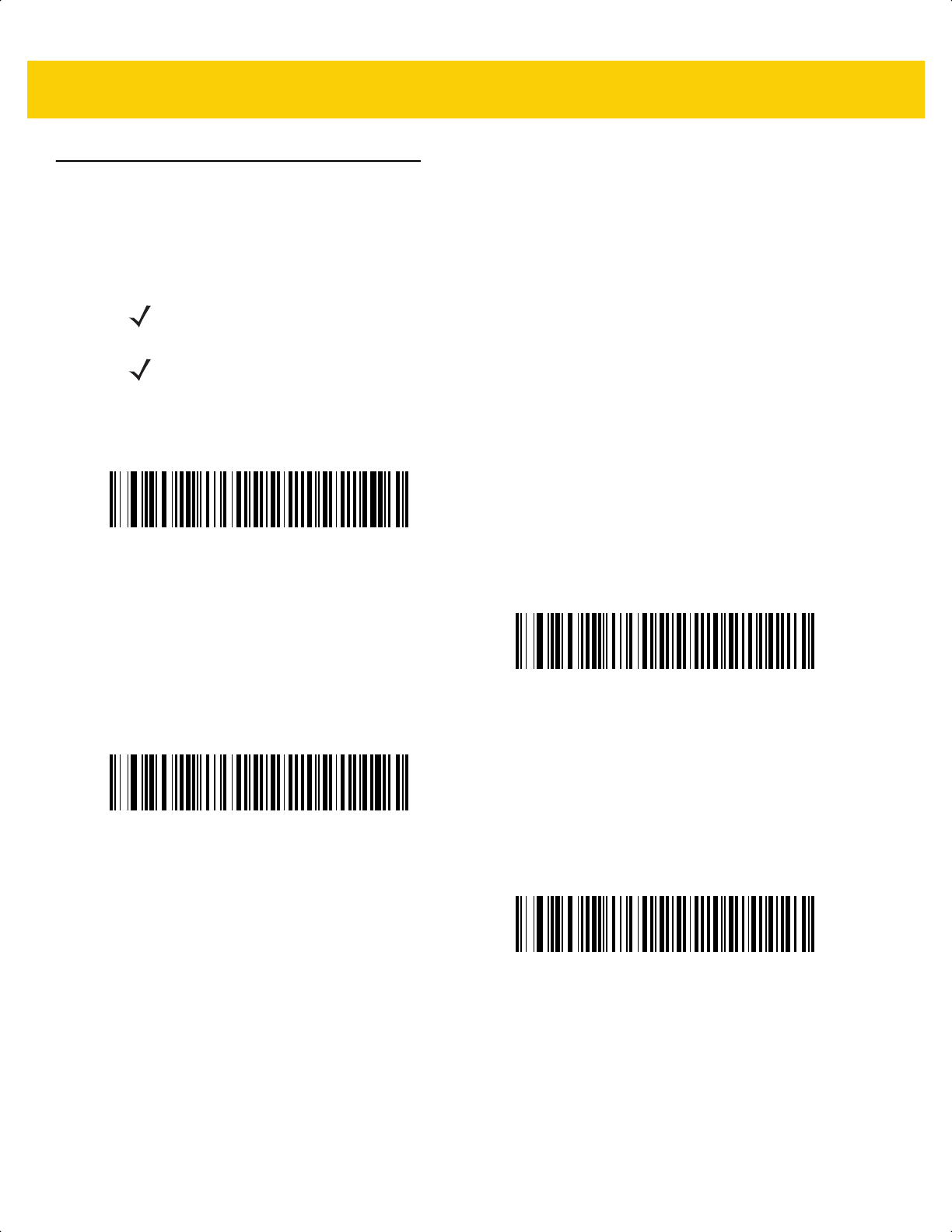
11 - 4 DS2278 Digital Scanner Product Reference Guide
IBM Host Parameters
Port Address
Scan one of the following bar codes to select the IBM 468X/469X port.
NOTE Scanning a Port Address bar code enables the RS-485 interface on the scanner.
NOTE For a list of supported scanner functionality by communication protocol, see
Appendix J, Communication Protocol Functionality.
*None
Hand-Held Scanner Emulation (Port 9B)
Non-IBM Scanner Emulation (Port 5B)
Table-Top Scanner Emulation (Port 17)
ds2278-prg-en.book Page 4

IBM 468X / 469X Interface 11 - 5
Convert Unknown to Code 39
Scan one of the following bar codes to enable or disable converting unknown bar code type data to Code 39.
RS-485 Beep Directive
The IBM RS-485 host can send a beeper configuration request to the scanner. Scan Ignore Beep Directive to
prevent the scanner from processing the host request. All directives are still acknowledged to the host as if they
were processed.
Enable Convert Unknown to Code 39
*Disable Convert Unknown to Code 39
Honor Beep Directive
*Ignore Beep Directive
ds2278-prg-en.book Page 5

11 - 6 DS2278 Digital Scanner Product Reference Guide
RS-485 Bar Code Configuration Directive
The IBM RS-485 host can enable and disable code types. Scan Ignore Bar Code Configuration Directive to
prevent the scanner from processing the host request. All directives are still acknowledged to the IBM RS-485 host
as if they were processed.
IBM-485 Specification Version
Parameter # 1729 (SSI # F8h 06h C1h)
The IBM interface specification version selected defines how code types are reported over the IBM interface.
When you scan Original Specification, only Symbologies that were historically supported on each individual port
are reported as known. When you scan Version 2.2, all Symbologies covered in the newer IBM specification are
reported as known with their respective code types.
Honor Bar Code Configuration Directive
*Ignore Bar Code Configuration Directive
*Original Specification
(0)
Version 2.2
(1)
ds2278-prg-en.book Page 6

CHAPTER 12 KEYBOARD WEDGE
INTERFACE
Introduction
This chapter describes how to set up a keyboard wedge interface with the cradle. The cradle connects between the
keyboard and host computer and translates bar code data into keystrokes, which the host accepts as if they
originated from the keyboard. This mode adds bar code reading functionality to a system designed for manual
keyboard input. Keyboard keystrokes are simply passed through.
The scanner ships with the settings shown in Table 12-1 on page 12-3 (also see Appendix A, Standard Default
Parameters
for all defaults). If the default values suit requirements, programming is not necessary.
Setting Parameters
To set feature values, scan a single bar code or a short bar code sequence. The settings are stored in non-volatile
memory and are preserved even when the scanner powers down.
To return all features to default values, scan a bar code in Default Parameters on page 5-5. Throughout the
programming bar code menus, asterisks (
*) indicate default values.
Scanning Sequence Examples
In most cases, scanning one bar code sets the parameter value. For example, to select a medium keystroke delay,
scan the Medium Delay (20 msec) bar code under Keystroke Delay on page 12-5. The scanner issues a fast
warble beep and the LED turns green, signifying a successful parameter entry.
Other parameters require scanning several bar codes. See the parameter descriptions for this procedure.
Errors While Scanning
Unless otherwise specified, to correct an error during a scanning sequence, just re-scan the correct parameter.
NOTE Most computer monitors allow scanning bar codes directly on the screen. When scanning from the screen,
be sure to set the document magnification to a level where you can see the bar code clearly, and bars
and/or spaces do not merge.
*Enable Parameter
Feature/option* Indicates default
ds2278-prg-en.book Page 1
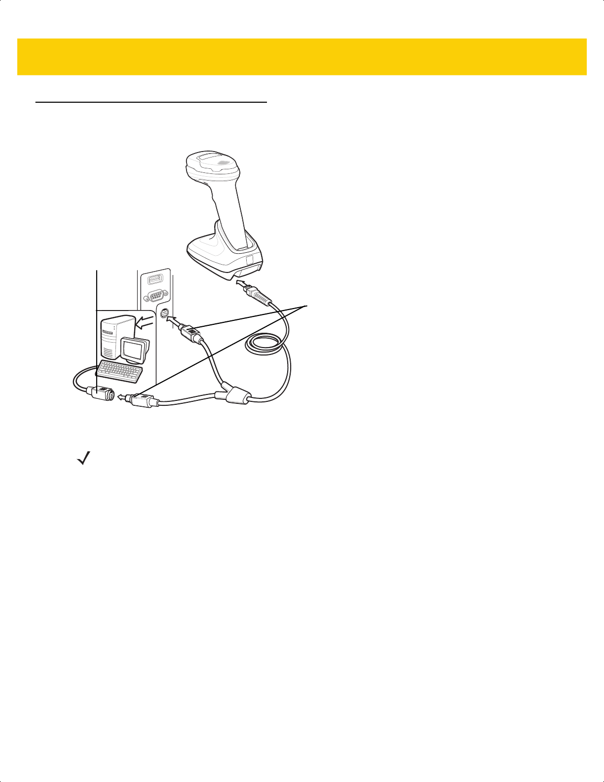
12 - 2 DS2278 Digital Scanner Product Reference Guide
Connecting a Keyboard Wedge Interface
Figure 12-1 Keyboard Wedge Connection
1. Turn off the host and unplug the keyboard connector.
2. Attach the modular connector of the Y-cable to the cable interface port on the cradle.
3. Connect the round male DIN host connector of the Y-cable to the keyboard port on the host device.
4. Connect the round female DIN keyboard connector of the Y-cable to the keyboard connector.
5. If required, attach the optional power supply to the connector in the middle of the Y-cable.
6. Ensure that all connections are secure.
7. Turn on the host system.
8. The digital scanner automatically detects the host interface type and uses the default setting. If the default (*)
does not meet your requirements, scan IBM PC/AT & IBM PC Compatibles on page 12-4.
9. To modify any other parameter options, scan the appropriate bar codes in this guide.
If problems occur with the system, see Troubleshooting on page 4-3.
Male DIN connectors
Keyboard
connector
NOTE Interface cables vary depending on configuration. The connectors can be different than those illustrated in
Figure 12-1, but the steps to connect the scanner are the same.
ds2278-prg-en.book Page 2

Keyboard Wedge Interface 12 - 3
Keyboard Wedge Parameter Defaults
Table 12-1 lists the defaults for Keyboard Wedge host parameters. To change any option, scan the appropriate bar
code(s) in Keyboard Wedge Host Parameters on page 12-4.
NOTE See Appendix B, Country Codes for Keyboard Wedge Country Keyboard Types (Country Codes).
See
Appendix A, Standard Default Parameters for all user preferences, hosts, symbologies, and
miscellaneous default parameters.
Table 12-1 Keyboard Wedge Host Default Table
Parameter Default Page Number
Keyboard Wedge Host Parameters
Keyboard Wedge Host Type IBM AT Notebook
12-4
Bar Codes with Unknown Characters Send Bar Codes with Unknown Characters
12-4
Keystroke Delay No Delay
12-5
Intra-keystroke Delay Disable
12-5
Alternate Numeric Keypad Emulation Enable
12-6
Quick Keypad Emulation Enable
12-6
Simulated Caps Lock Disable
12-7
Caps Lock Override Disable
12-7
Convert Case Do Not Convert
12-8
Function Key Mapping Disable
12-8
FN1 Substitution Disable
12-9
Send Make and Break Send
12-9
ds2278-prg-en.book Page 3
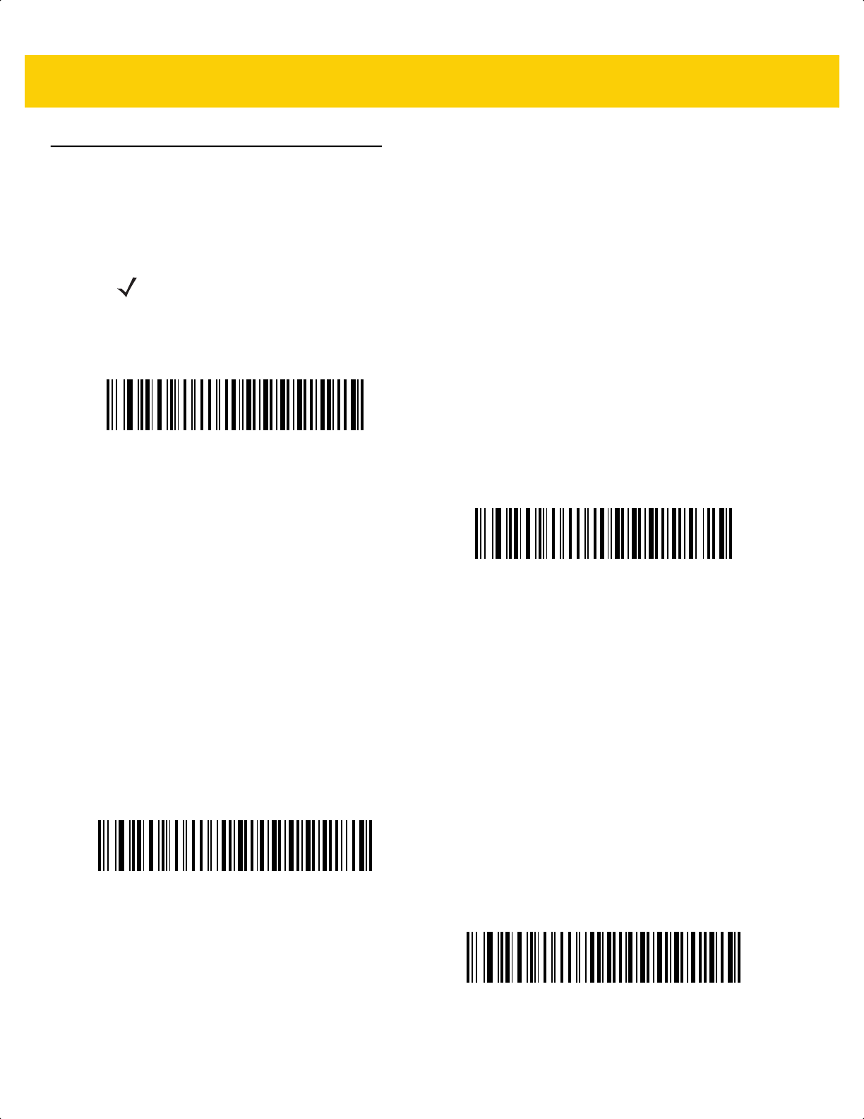
12 - 4 DS2278 Digital Scanner Product Reference Guide
Keyboard Wedge Host Parameters
Keyboard Wedge Host Types
Select the Keyboard Wedge host by scanning one of the bar codes below.
Bar Codes with Unknown Characters
Unknown characters are characters the host does not recognize. Scan Send Bar Codes With Unknown
Characters to send all bar code data except for unknown characters. The scanner issues no error beeps.
Scan Do Not Send Bar Codes With Unknown Characters to send bar code data up to the first unknown
character. The scanner issues an error beep.
NOTE For a list of supported scanner functionality by communication protocol, see
Appendix J, Communication Protocol Functionality.
IBM PC/AT & IBM PC Compatibles
*IBM AT Notebook
*Send Bar Codes with Unknown Characters
Do Not Send Bar Codes with Unknown Characters
ds2278-prg-en.book Page 4

Keyboard Wedge Interface 12 - 5
Keystroke Delay
This is the delay in milliseconds between emulated keystrokes. Scan one of the following bar codes to increase the
delay when hosts require a slower data transmission.
Intra-keystroke Delay
Scan Enable Intra-keystroke Delay to insert an additional delay between each emulated key press and release.
This also sets Keystroke Delay to a minimum of 5 msec.
*No Delay
Medium Delay (20 msec)
Long Delay (40 msec)
Enable Intra-keystroke Delay
*Disable Intra-keystroke Delay
ds2278-prg-en.book Page 5

12 - 6 DS2278 Digital Scanner Product Reference Guide
Alternate Numeric Keypad Emulation
This allows emulation of most other country keyboard types not listed in Appendix B, Country Codes in a
Microsoft
®
operating system environment.
Quick Keypad Emulation
This enables faster keypad emulation where character value sequences are only sent for characters not found on
the keyboard.
NOTE If your keyboard type is not listed in the country code list (see USB and Keyboard Wedge Country
Keyboard Types (Country Codes) on page B-2), disable Quick Keypad Emulation on page 12-6 and
ensure Alternate Numeric Keypad Emulation on page 12-6 is enabled.
*Enable Alternate Numeric Keypad
Disable Alternate Numeric Keypad
NOTE This option applies only when Alternate Numeric Keypad Emulation is enabled.
*Enable Quick Keypad Emulation
Disable Quick Keypad Emulation
ds2278-prg-en.book Page 6
Keyboard Wedge Interface 12 - 7
Simulated Caps Lock
Scan Enable Caps Lock to invert upper and lower case characters on the bar code as if the Caps Lock state is
enabled on the keyboard. This inversion occurs regardless of the keyboard’s Caps Lock state. Note that Simulated
Caps Lock applies to ASCII alpha characters only.
Caps Lock Override
Scan Enable Caps Lock Override for AT or AT Notebook hosts to preserve the case of the data regardless of the
state of the Caps Lock key. Therefore, an ‘A’ in the bar code transmits as an ‘A’ regardless of the setting of the
keyboard’s Caps Lock key.
Enable Caps Lock
*Disable Caps Lock
Enable Caps Lock Override
*Disable Caps Lock Override
NOTE If both Simulated Caps Lock and Caps Lock Override are enabled, Caps Lock Override takes precedence.
ds2278-prg-en.book Page 7
12 - 8 DS2278 Digital Scanner Product Reference Guide
Convert Case
Scan one of the following bar codes to convert all bar code data to the selected case.
Function Key Mapping
ASCII values under 32 are normally sent as control key sequences (see Table I-1 on page I-1). Scan Enable
Function Key Mapping to send the keys in bold in place of the standard key mapping. Table entries that do not
have a bold entry remain the same whether or not you enable this parameter.
NOTE Convert Case applies to ASCII characters only.
Convert to Upper Case
Convert to Lower Case
*Do Not Convert
Enable Function Key Mapping
*Disable Function Key Mapping
ds2278-prg-en.book Page 8
Keyboard Wedge Interface 12 - 9
FN1 Substitution
Scan Enable FN1 Substitution to replace FN1 characters in an EAN128 bar code with a user-selected keystroke
(see FN1 Substitution Values on page 5-36).
Send Make and Break
Scan Send Make and Break Scan Codes to prevent sending the scan codes for releasing a key.
Enable FN1 Substitution
*Disable FN1 Substitution
*Send Make and Break Scan Codes
Send Make Scan Code Only
NOTE Windows-based systems must use Send Make and Break Scan Codes.
ds2278-prg-en.book Page 9
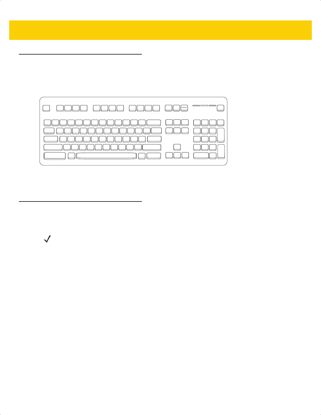
12 - 10DS2278 Digital Scanner Product Reference Guide
Keyboard Map
The following keyboard map is a reference for prefix/suffix keystroke parameters. To program the prefix/suffix
values, see the bar codes on page 5-33.
Figure 12-2 IBM PS2 Type Keyboard
ASCII Character Set for Keyboard Wedge
See Appendix I, ASCII Character Sets for the following:
• ASCII Character Set (Table I-1 on page I-1)
• ALT Key Character Set (Table I-2 on page I-6)
• GUI Key Character Set (Table I-3 on page I-7)
• F Key Character Set (Table I-5 on page I-10)
• Numeric Key Character Set (Table I-6 on page I-11)
• Extended Key Character Set (Table I-7 on page I-12).
7013
7014 5001 5002 5003 5004 5005 5006 5007 5008 5009 5010
7013
5011
7010 7007
7006
7001
5012
7008
7009
7011
7012
7003
7002 7004 7005
7017 7016
7015
7018
NOTE Code 39 Full ASCII interprets the bar code special character ($ + % /) preceding a Code 39 character and
assigns an ASCII character value to the pair. For example, if you enable Code 39 Full ASCII and scan +B,
it transmits as b, %J as ?, and %V as @. Scanning ABC%I outputs the keystroke equivalent of ABC >.
ds2278-prg-en.book Page 10

CHAPTER 13 SYMBOLOGIES
Introduction
You can program the scanner to perform various functions, or activate different features. This chapter describes
symbology features and provides programming bar codes for selecting these features.
The scanner ships with the settings shown in Table 13-1 on page 13-2 (also see Appendix A, Standard Default
Parameters for all defaults). If the default values suit requirements, programming is not necessary.
Setting Parameters
To set feature values, scan a single bar code or a short bar code sequence. The settings are stored in non-volatile
memory and are preserved even when the scanner powers down.
If not using a USB cable, select a host type (see each host chapter for specific host information) after the power-up
beeps sound. This is only necessary upon the first power-up when connected to a new host.
To return all features to default values, see Default Parameters on page 5-5. Throughout the programming bar
code menus, asterisks (*) indicate default values.
NOTE Most computer monitors allow scanning bar codes directly on the screen. When scanning from the screen,
be sure to set the document magnification to a level where you can see the bar code clearly, and bars
and/or spaces do not merge.
*Enable Parameter
Feature/option* Indicates default
ds2278-prg-en.book Page 1

13 - 2 DS2278 Digital Scanner Product Reference Guide
Scanning Sequence Examples
In most cases, scanning one bar code sets the parameter value. For example, to transmit bar code data without the
UPC-A check digit, scan the Do Not Transmit UPC-A Check Digit bar code under Transmit UPC-A Check Digit
on page 13-18. The scanner issues a fast warble beep and the LED turns green, signifying a successful parameter
entry.
Other parameters, such as Set Lengths for D 2 of 5, require scanning several bar codes. See the parameter
descriptions for this procedure.
Errors While Scanning
Unless otherwise specified, to correct an error during a scanning sequence, just re-scan the correct parameter.
Symbology Parameter Defaults
Table 13-1 lists defaults for all symbology parameters. Change these values in one of two ways:
• Scan the appropriate bar codes in this chapter. The new value replaces the standard default value in
memory. To recall the default parameter values, see Default Parameters on page 5-5.
• Configure the scanner using the 123Scan
configuration program. See Chapter 13, Symbologies.
NOTE See Appendix A, Standard Default Parameters for all user preference, host, symbology, and
miscellaneous default parameters.
Table 13-1 Symbology Parameter Defaults
Parameter
Parameter
Number
1
SSI Number
2
Default
Page
Number
Enable/Disable All Code Types
13-8
1D Symbologies
UPC/EAN/JAN
UPC-A 1 01h Enable 13-9
UPC-E 2 02h Enable 13-9
UPC-E1 12 0Ch Disable 13-10
EAN-8/JAN 8 4 04h Enable 13-10
EAN-13/JAN 13 3 03h Enable 13-11
Bookland EAN 83 53h Disable 13-11
Bookland ISBN Format 576 F1h 40h ISBN-10 13-12
ISSN EAN 617 F1h 69h Disable 13-12
1. Parameter number decimal values are used for programming via RSM commands.
2. SSI number hex values are used for programming via SSI commands.
ds2278-prg-en.book Page 2

Symbologies 13 - 3
Decode UPC/EAN/JAN Supplementals
(2 and 5 digits)
16 10h Ignore 13-13
User-Programmable Supplementals
Supplemental 1:
Supplemental 2:
579
580
F1h 43h
F1h 44h
000 13-16
UPC/EAN/JAN Supplemental Redundancy 80 50h 10 13-16
Decode UPC/EAN/JAN Supplemental AIM
ID Format
672 F1h A0h Combined 13-17
Transmit UPC-A Check Digit 40 28h Enable 13-18
Transmit UPC-E Check Digit 41 29h Enable 13-18
Transmit UPC-E1 Check Digit 42 2Ah Enable 13-19
Transmit Ean-8 Check Digit 1881 F8 07 59h Enable 13-19
Transmit Ean-13 Check Digit 1882 F8 07 5Ah Enable 13-20
UPC-A Preamble 34 22h System Character 13-21
UPC-E Preamble 35 23h System Character 13-22
UPC-E1 Preamble 36 24h System Character 13-23
Convert UPC-E to UPC-A 37 25h Disable 13-24
Convert UPC-E1 to UPC-A 38 26h Disable 13-24
EAN/JAN Zero Extend 39 27h Disable 13-25
UCC Coupon Extended Code 85 55h Disable 13-25
Coupon Report 730 F1h DAh New Coupon
Format
13-26
UPC Reduced Quiet Zone 1289 F8h 05h 09h Disable 13-26
Code 128
Code 128 8 08h Enable 13-27
Set Lengths for Code 128 209, 210 D1h, D2h 1 - 55 13-27
GS1-128 (formerly UCC/EAN-128) 14 0Eh Enable 13-28
ISBT 128 84 54h Disable 13-29
ISBT Concatenation 577 F1h 41h Disable 13-30
Check ISBT Table 578 F1h 42h Enable 13-31
Table 13-1 Symbology Parameter Defaults (Continued)
Parameter
Parameter
Number
1
SSI Number
2
Default
Page
Number
1. Parameter number decimal values are used for programming via RSM commands.
2. SSI number hex values are used for programming via SSI commands.
ds2278-prg-en.book Page 3

13 - 4 DS2278 Digital Scanner Product Reference Guide
ISBT Concatenation Redundancy 223 DFh 10 13-31
Code 128 <FNC4> 1254 F8h 04h E6h Honor 13-32
Code 128 Security Level 751 F1h EFh Security Level 1 13-32
Code 128 Reduced Quiet Zone 1208 F8h 04h B8h Disable 13-33
Code 39
Code 39 0 00h Enable 13-34
Trioptic Code 39 13 0Dh Disable 13-34
Convert Code 39 to Code 32
(Italian Pharmacy Code)
86 56h Disable 13-35
Code 32 Prefix 231 E7h Disable 13-35
Set Lengths for Code 39 18, 19 12h, 13h 1 - 55 13-36
Code 39 Check Digit Verification 48 30h Disable 13-37
Transmit Code 39 Check Digit 43 2Bh Disable 13-38
Code 39 Full ASCII Conversion 17 11h Disable 13-38
Code 39 Security Level 750 F1h EEh Security Level 1 13-39
Code 39 Reduced Quiet Zone 1209 F8h 04h B9h Disable 13-41
Code 93
Code 93 9 09h Enable 13-41
Set Lengths for Code 93 26, 27 1Ah, 1Bh 1 - 55 13-42
Code 11
Code 11 10 0Ah Disable 13-44
Set Lengths for Code 11 28, 29 1Ch, 1Dh 4 to 55 13-44
Code 11 Check Digit Verification 52 34h Disable 13-46
Transmit Code 11 Check Digit(s) 47 2Fh Disable 13-47
Interleaved 2 of 5 (ITF/I 2 of 5)
Interleaved 2 of 5 6 06h Enable 13-47
Set Lengths for Interleaved 2 of 5 22, 23 16h, 17h 6 to 55 13-48
Interleaved 2 of 5 Check Digit Verification 49 31h Disable 13-50
Transmit Interleaved 2 of 5 Check Digit 44 2Ch Disable 13-51
Table 13-1 Symbology Parameter Defaults (Continued)
Parameter
Parameter
Number
1
SSI Number
2
Default
Page
Number
1. Parameter number decimal values are used for programming via RSM commands.
2. SSI number hex values are used for programming via SSI commands.
ds2278-prg-en.book Page 4

Symbologies 13 - 5
Convert Interleaved 2 of 5 to EAN-13 82 52h Disable 13-51
Febraban 1750 F8h 06h D6h Disable 13-52
Interleaved 2 of 5 Security Level 1121 F8h 04h 61h Security Level 1 13-53
Interleaved 2 of 5 Reduced Quiet Zone 1210 F8h 04h BAh Disable 13-54
Discrete 2 of 5 (DTF/D 2 of 5)
Discrete 2 of 5 5 05h Disable 13-54
Set Lengths for Discrete 2 of 5 20, 21 14h 15h 1 to 55 13-55
Codabar (NW - 7)
Codabar 7 07h Enable 13-57
Set Lengths for Codabar 24, 25 18h, 19h 4 to 55 13-57
CLSI Editing 54 36h Disable 13-59
NOTIS Editing 55 37h Disable 13-59
Codabar Upper or Lower Case Start/
Stop Characters Detection
855 F2h 57h Upper Case 13-60
Codabar Mod 16 Check Digit 1784 F8h 06h F8h Disable 13-60
Transmit Codabar Check Digit 704 F1h C0h Disable 13-61
MSI
MSI 11 0Bh Disable 13-61
Set Lengths for MSI 30, 31 1Eh, 1Fh 4 to 55 13-62
MSI Check Digits 50 32h One 13-64
Transmit MSI Check Digit 46 2Eh Disable 13-64
MSI Check Digit Algorithm 51 33h Mod 10/Mod 10 13-65
MSI Reduced Quiet Zone 1392 F8h 05h 70h Disable
13-65
Chinese 2 of 5
Chinese 2 of 5 408 F0h 98h Disable 13-66
Matrix 2 of 5
Matrix 2 of 5 618 F1h 6Ah Disable 13-66
Matrix 2 of 5 Lengths 619
620
F1h 6Bh
F1h 6Ch
4 to 55 13-67
Table 13-1 Symbology Parameter Defaults (Continued)
Parameter
Parameter
Number
1
SSI Number
2
Default
Page
Number
1. Parameter number decimal values are used for programming via RSM commands.
2. SSI number hex values are used for programming via SSI commands.
ds2278-prg-en.book Page 5

13 - 6 DS2278 Digital Scanner Product Reference Guide
Matrix 2 of 5 Check Digit 622 F1h 6Eh Disable 13-68
Transmit Matrix 2 of 5 Check Digit 623 F1h 6Fh Disable 13-69
Korean 3 of 5
Korean 3 of 5 581 F1h 45h Disable 13-69
Inverse 1D
586 F1h 4Ah Regular 13-70
GS1 DataBar
GS1 DataBar Omnidirectional (formerly
GS1 DataBar-14), GS1 DataBar Truncated,
GS1 DataBar Stacked, GS1 DataBar
Stacked Omnidirectional
338 F0h 52h Enable 13-71
GS1 DataBar Limited 339 F0h 53h Enable 13-71
GS1 DataBar Expanded, GS1 DataBar
Expanded Stacked
340 F0h 54h Enable 13-72
Convert GS1 DataBar to UPC/EAN/JAN 397 F0h 8Dh Disable 13-72
GS1 DataBar Limited Margin Check 728 F1h D8h
Level 3 13-73
GS1 DataBar Security Level 1706 F8h 06h AAh
Level 1 13-74
Symbology-Specific Security Features
Redundancy Level 78 4Eh 1 13-75
Security Level 77 4Dh 1 13-77
1D Quiet Zone Level 1288 F8h 05h 08h 1 13-78
Intercharacter Gap Size 381 F0h 7Dh Normal 13-79
Composite Codes
Composite CC-C 341 F0h 55h Disable 13-79
Composite CC-A/B 342 F0h 56h Disable 13-80
Composite TLC-39 371 F0h 73h Disable 13-80
Composite Inverse 1113 F8h 04h 59h Regular Only
13-81
UPC Composite Mode 344 F0h 58h UPC Never Linked 13-82
Composite Beep Mode 398 F0h 8Eh Beep As Each
Code Type is
Decoded
13-83
Table 13-1 Symbology Parameter Defaults (Continued)
Parameter
Parameter
Number
1
SSI Number
2
Default
Page
Number
1. Parameter number decimal values are used for programming via RSM commands.
2. SSI number hex values are used for programming via SSI commands.
ds2278-prg-en.book Page 6

Symbologies 13 - 7
GS1-128 Emulation Mode for UCC/EAN
Composite Codes
427 F0h ABh Disable 13-83
2D Symbologies
PDF417 15 0Fh Enable 13-84
MicroPDF417 227 E3h Disable 13-84
Code 128 Emulation 123 7Bh Disable 13-85
Data Matrix 292 F0h 24h Enable 13-86
GS1 Data Matrix 1336 F8h 05h 38h Disable 13-86
Data Matrix Inverse 588 F1h 4Ch Inverse Autodetect 13-87
Decode Data Matrix Mirror Images 537 F1h 19h Auto 13-88
Maxicode 294 F0h 26h Disable 13-89
QR Code 293 F0h 25h Enable 13-89
GS1 QR 1343 F8h 05h 3Fh Disable 13-90
MicroQR 573 F1h 3Dh Enable 13-90
Weblink QR 1947 F8 07 9Bh Enable 13-91
Linked QR 1847 737h Linked QR Only 13-92
Aztec 574 F1h 3Eh Enable 13-93
Aztec Inverse 589 F1h 4Dh Inverse Autodetect 13-93
Han Xin 1167 F8h 04h 8Fh Disable 13-94
Han Xin Inverse 1168 F8h 04h 90h Regular 13-94
Grid Matrix 1718 F8 06 B6 Disable 13-95
Grid Matrix Inverse 1719 F8 06 B7 Regular Only 13-95
Grid Matrix Mirror 1736 F8 06 C8 Regular Only 13-96
DotCode 1906 F8 07 72h Disable 13-97
DotCode Inverse 1907 F8 07 73h Autodetect 13-98
DotCode Mirrored 1908 F8 07 74h Autodetect 13-99
DotCode Prioritize 1937 F8 07 91h Enable 13-100
DotCode Erasure Limit 2063 F8 08 0F 10 13-100
Table 13-1 Symbology Parameter Defaults (Continued)
Parameter
Parameter
Number
1
SSI Number
2
Default
Page
Number
1. Parameter number decimal values are used for programming via RSM commands.
2. SSI number hex values are used for programming via SSI commands.
ds2278-prg-en.book Page 7
13 - 8 DS2278 Digital Scanner Product Reference Guide
Enable/Disable All Code Types
Scan the Disable All Code Types bar code to disable all symbologies. This is useful when enabling only a few
code types.
Scan Enable All Code Types to enable all symbologies. This is useful if you need to disable only a few code
types.
Postal Codes
US Postnet 89 59h Disable 13-102
US Planet 90 5Ah Disable 13-102
Transmit US Postal Check Digit 95 5Fh Enable 13-103
UK Postal 91 5Bh Disable 13-103
Transmit UK Postal Check Digit 96 60h Enable 13-104
Japan Postal 290 F0h 22h Disable 13-104
Australia Post 291 F0h 23h Disable 13-105
Australia Post Format 718 F1h CEh Autodiscriminate 13-106
Netherlands KIX Code 326 F0h 46h Disable 13-107
USPS 4CB/One Code/Intelligent Mail 592 F1h 50h Disable 13-107
UPU FICS Postal 611 F1h 63h Disable 13-108
Mailmark 1337 F8h 05h 39h Disable 13-108
Table 13-1 Symbology Parameter Defaults (Continued)
Parameter
Parameter
Number
1
SSI Number
2
Default
Page
Number
1. Parameter number decimal values are used for programming via RSM commands.
2. SSI number hex values are used for programming via SSI commands.
Disable All Code Types
Enable All Code Types
ds2278-prg-en.book Page 8

Symbologies 13 - 9
UPC/EAN/JAN
UPC-A
Parameter # 1
SSI # 01h
Scan one of the following bar codes to enable or disable UPC-A.
UPC-E
Parameter # 2
SSI # 02h
Scan one of the following bar codes to enable or disable UPC-E.
*Enable UPC-A
(1)
Disable UPC-A
(0)
*Enable UPC-E
(1)
Disable UPC-E
(0)
ds2278-prg-en.book Page 9
13 - 10 DS2278 Digital Scanner Product Reference Guide
UPC-E1
Parameter # 12
SSI # 0Ch
Scan one of the following bar codes to enable or disable UPC-E1.
EAN-8/JAN-8
Parameter # 4
SSI # 04h
Scan one of the following bar codes to enable or disable EAN-8/JAN-8.
NOTE UPC-E1 is not a UCC (Uniform Code Council) approved symbology.
Enable UPC-E1
(1)
*Disable UPC-E1
(0)
*Enable EAN-8/JAN-8
(1)
Disable EAN-8/JAN-8
(0)
ds2278-prg-en.book Page 10

Symbologies 13 - 11
EAN-13/JAN-13
Parameter # 3
SSI # 03h
Scan one of the following bar codes to enable or disable EAN-13/JAN-13.
Bookland EAN
Parameter # 83
SSI # 53h
Scan one of the following bar codes to enable or disable Bookland EAN.
*Enable EAN-13/JAN-13
(1)
Disable EAN-13/JAN-13
(0)
Enable Bookland EAN
(1)
*Disable Bookland EAN
(0)
NOTE If you enable Bookland EAN, select a Bookland ISBN Format. Also set Decode UPC/EAN/JAN Supplementals
on page 13-13 to either Decode UPC/EAN/JAN with Supplementals Only, Autodiscriminate UPC/EAN/JAN
With Supplementals, or Enable 978/979 Supplemental Mode.
ds2278-prg-en.book Page 11
13 - 12 DS2278 Digital Scanner Product Reference Guide
Bookland ISBN Format
Parameter # 576
SSI # F1h 40h
If you enabled Bookland EAN using Bookland EAN on page 13-11, select one of the following formats for Bookland
data:
• Bookland ISBN-10 - The scanner reports Bookland data starting with 978 in traditional 10-digit format with
the special Bookland check digit for backward-compatibility. Data starting with 979 is not considered
Bookland in this mode.
• Bookland ISBN-13 - The scanner reports Bookland data (starting with either 978 or 979) as EAN-13 in
13-digit format to meet the 2007 ISBN-13 protocol.
ISSN EAN
Parameter # 617
SSI # F1h 69h
Scan one of the following bar codes to enable or disable ISSN EAN.
*Bookland ISBN-10
(0)
Bookland ISBN-13
(1)
NOTE For Bookland EAN to function properly, first enable Bookland EAN using Bookland EAN on page 13-11,
and then set Decode UPC/EAN/JAN Supplementals on page 13-13 to either Decode UPC/EAN/JAN with
Supplementals Only, Autodiscriminate UPC/EAN/JAN With Supplementals, or Enable 978/979
Supplemental Mode.
Enable ISSN EAN
(1)
*Disable ISSN EAN
(0)
ds2278-prg-en.book Page 12

Symbologies 13 - 13
Decode UPC/EAN/JAN Supplementals
Parameter # 16
SSI # 10h
Supplementals are bar codes appended according to specific format conventions (e.g., UPC A+2, UPC E+2,
EAN-13+2). The following options are available:
• Decode UPC/EAN/JAN with Supplementals Only - The scanner only decodes UPC/EAN/JAN symbols
with supplemental characters, and ignores symbols without supplementals.
• Ignore UPC/EAN/JAN Supplementals - When presented with a UPC/EAN/JAN plus supplemental
symbol, the scanner decodes UPC/EAN/JAN and ignores the supplemental characters.
• Autodiscriminate UPC/EAN/JAN with Supplementals - The scanner decodes UPC/EAN/JAN symbols
with supplemental characters immediately. If the symbol does not have a supplemental, the scanner must
decode the bar code the number of times set via UPC/EAN/JAN Supplemental Redundancy on page 13-16
before transmitting its data to confirm that there is no supplemental.
Select one of the following Supplemental Mode options to immediately transmit EAN-13 bar codes starting
with that prefix that have supplemental characters. If the symbol does not have a supplemental, the scanner
must decode the bar code the number of times set via UPC/EAN/JAN Supplemental Redundancy on page
13-16 before transmitting the data to confirm that there is no supplemental. The scanner transmits
UPC/EAN/JAN bar codes that do not have that prefix immediately.
• Enable 378/379 Supplemental Mode
• Enable 978/979 Supplemental Mode
• Enable 977 Supplemental Mode
• Enable 414/419/434/439 Supplemental Mode
• Enable 491 Supplemental Mode
• Enable Smart Supplemental Mode - This applies to EAN-13 bar codes starting with any prefix listed
previously.
• Supplemental User-Programmable Type 1 - This applies to EAN-13 bar codes starting with a 3-digit
user-defined prefix. Set this using User-Programmable Supplementals on page 13-16.
• Supplemental User-Programmable Type 1 and 2 - This applies to EAN-13 bar codes starting with either of
two 3-digit user-defined prefixes. Set the prefixes using User-Programmable Supplementals on page 13-16.
• Smart Supplemental Plus User-Programmable 1 - This applies to EAN-13 bar codes starting with any
prefix listed previously or the prefix set using User-Programmable Supplementals on page 13-16.
• Smart Supplemental Plus User-Programmable 1 and 2 - This applies to EAN-13 bar codes starting with
any prefix listed previously or one of the two user-defined prefixes set using User-Programmable
Supplementals on page 13-16.
NOTE If you select 978/979 Supplemental Mode and are scanning Bookland EAN bar codes, see Bookland EAN
on page 13-11 to enable Bookland EAN, and select a format using Bookland ISBN Format on page 13-12.
NOTE To minimize the risk of invalid data transmission, select either to decode or ignore supplemental
characters.
ds2278-prg-en.book Page 13
13 - 14 DS2278 Digital Scanner Product Reference Guide
Decode UPC/EAN/JAN Supplementals (continued)
Decode UPC/EAN/JAN With Supplementals Only
(1)
*Ignore UPC/EAN/JAN Supplementals
(0)
Autodiscriminate UPC/EAN/JAN with Supplementals
(2)
Enable 378/379 Supplemental Mode
(4)
Enable 978/979 Supplemental Mode
(5)
Enable 977 Supplemental Mode
(7)
ds2278-prg-en.book Page 14
Symbologies 13 - 15
Decode UPC/EAN/JAN Supplementals (continued)
Enable 414/419/434/439 Supplemental Mode
(6)
Enable 491 Supplemental Mode
(8)
Enable Smart Supplemental Mode
(3)
Supplemental User-Programmable Type 1
(9)
Supplemental User-Programmable Type 1 and 2
(10)
Smart Supplemental Plus User-Programmable 1
(11)
Smart Supplemental Plus User-Programmable 1 and 2
(12)
ds2278-prg-en.book Page 15

13 - 16 DS2278 Digital Scanner Product Reference Guide
User-Programmable Supplementals
Supplemental 1: Parameter # 579
SSI # F1h 43h
Supplemental 2: Parameter # 580
SSI # F1h 44h
If you selected a Supplemental User-Programmable option from Decode UPC/EAN/JAN Supplementals on page
13-13, scan User-Programmable Supplemental 1, and then scan three bar codes from Appendix G, Numeric
Bar Codes to set the 3-digit prefix. To set a second 3-digit prefix, scan User-Programmable Supplemental 2, and
then scan three bar codes from Appendix G, Numeric Bar Codes. The default is 000 (zeroes).
UPC/EAN/JAN Supplemental Redundancy
Parameter # 80
SSI # 50h
If you selected Autodiscriminate UPC/EAN/JAN with Supplementals, this option sets the number of times to
decode a symbol without supplementals before transmission. The range is from two to 30. Five or above is
recommended when decoding a mix of UPC/EAN/JAN symbols with and without supplementals.
The default is 10.
To set a redundancy value, scan the following bar code, and then scan two bar codes from Appendix G, Numeric
Bar Codes. Enter a leading zero for single digit numbers. To correct an error or change a selection, scan Cancel
on page G-3.
User-Programmable Supplemental 1
User-Programmable Supplemental 2
UPC/EAN/JAN Supplemental Redundancy
ds2278-prg-en.book Page 16

Symbologies 13 - 17
UPC/EAN/JAN Supplemental AIM ID Format
Parameter # 672
SSI # F1h A0h
If Transmit Code ID Character on page 5-32 is set to AIM Code ID Character, scan one of the following bar codes to
select an output format when reporting UPC/EAN/JAN bar codes with supplementals:
•
Separate - Transmit UPC/EAN/JAN with supplementals with separate AIM IDs but one transmission, i.e.,
]E<0 or 4><data>]E<1 or 2>[supplemental data]
• Combined – Transmit UPC/EAN/JAN with supplementals with one AIM ID and one transmission, i.e.,
]E3<data+supplemental data>
• Separate Transmissions - Transmit UPC/EAN/JAN with supplementals with separate AIM IDs and separate
transmissions, i.e.,
]E<0 or 4><data>
]E<1 or 2>[supplemental data]
Separate
(0)
*Combined
(1)
Separate Transmissions
(2)
ds2278-prg-en.book Page 17

13 - 18 DS2278 Digital Scanner Product Reference Guide
Transmit UPC-A Check Digit
Parameter # 40
SSI # 28h
The check digit is the last character of the symbol used to verify the integrity of the data. Scan one of the following
bar codes to transmit the bar code data with or without the UPC-A check digit. It is always verified to guarantee the
integrity of the data.
Transmit UPC-E Check Digit
Parameter # 41
SSI # 29h
The check digit is the last character of the symbol used to verify the integrity of the data. Scan one of the following
bar codes to transmit the bar code data with or without the UPC-E check digit. It is always verified to guarantee the
integrity of the data.
*Transmit UPC-A Check Digit
(1)
Do Not Transmit UPC-A Check Digit
(0)
*Transmit UPC-E Check Digit
(1)
Do Not Transmit UPC-E Check Digit
(0)
ds2278-prg-en.book Page 18

Symbologies 13 - 19
Transmit UPC-E1 Check Digit
Parameter # 42
SSI # 2Ah
The check digit is the last character of the symbol used to verify the integrity of the data. Scan one of the following
bar codes to transmit the bar code data with or without the UPC-E1 check digit. It is always verified to guarantee
the integrity of the data.
Transmit EAN-8 Check Digit
Parameter # 1881
SSI # F8 07 59h
The check digit is the last character of the symbol used to verify the integrity of the data. Scan one of the following
barcodes to transmit the barcode data with or without the EAN-8 check digit. It is always verified to guarantee the
integrity of the data.
*Transmit UPC-E1 Check Digit
(1)
Do Not Transmit UPC-E1 Check Digit
(0)
*Transmit EAN-8 Check Digit
(1)
Do Not Transmit EAN-8 Check Digit
(0)
ds2278-prg-en.book Page 19

13 - 20 DS2278 Digital Scanner Product Reference Guide
Transmit EAN-13 Check Digit
Parameter # 1882
SSI # F8 07 5Ah
The check digit is the last character of the symbol used to verify the integrity of the data. Scan one of the following
barcodes to transmit the barcode data with or without the EAN-13 check digit. It is always verified to guarantee the
integrity of the data.
*Transmit EAN-13 Check Digit
(1)
Do Not Transmit EAN-13 Check Digit
(0)
ds2278-prg-en.book Page 20

Symbologies 13 - 21
UPC-A Preamble
Parameter # 34
SSI # 22h
Preamble characters are part of the UPC symbol, and include Country Code and System Character. Select the
appropriate option for transmitting a UPC-A preamble to match the host system:
• Transmit System Character only
• Transmit System Character and Country Code (“0” for USA)
• Transmit no preamble.
No Preamble (<DATA>)
(0)
*System Character
(<SYSTEM CHARACTER> <DATA>)
(1)
System Character & Country Code
(< COUNTRY CODE> <SYSTEM CHARACTER> <DATA>)
(2)
ds2278-prg-en.book Page 21

13 - 22 DS2278 Digital Scanner Product Reference Guide
UPC-E Preamble
Parameter # 35
SSI # 23h
Preamble characters are part of the UPC symbol, and include Country Code and System Character. Select the
appropriate option for transmitting a UPC-E preamble to match the host system:
• Transmit System Character only
• Transmit System Character and Country Code (“0” for USA)
• Transmit no preamble.
No Preamble (<DATA>)
(0)
*System Character
(<SYSTEM CHARACTER> <DATA>)
(1)
System Character & Country Code
(< COUNTRY CODE> <SYSTEM CHARACTER> <DATA>)
(2)
ds2278-prg-en.book Page 22

Symbologies 13 - 23
UPC-E1 Preamble
Parameter # 36
SSI # 24h
Preamble characters are part of the UPC symbol, and include Country Code and System Character. Select the
appropriate option for transmitting a UPC-E1 preamble to match the host system:
• Transmit System Character only
• Transmit System Character and Country Code (“0” for USA)
• Transmit no preamble.
No Preamble (<DATA>)
(0)
*System Character
(<SYSTEM CHARACTER> <DATA>)
(1)
System Character & Country Code
(< COUNTRY CODE> <SYSTEM CHARACTER> <DATA>)
(2)
ds2278-prg-en.book Page 23

13 - 24 DS2278 Digital Scanner Product Reference Guide
Convert UPC-E to UPC-A
Parameter # 37
SSI # 25h
Enable this to convert UPC-E (zero suppressed) decoded data to UPC-A format before transmission. After
conversion, the data follows UPC-A format and is affected by UPC-A programming selections (e.g., Preamble,
Check Digit).
Disable this to transmit UPC-E decoded data as UPC-E data, without conversion.
Convert UPC-E1 to UPC-A
Parameter # 38
SSI # 26h
Scan Convert UPC-E1 to UPC-A (Enable) to convert UPC-E1 decoded data to UPC-A format before
transmission. After conversion, the data follows UPC-A format and is affected by UPC-A programming selections
(e.g., Preamble, Check Digit).
Scan Do Not Convert UPC-E1 to UPC-A (Disable) to transmit UPC-E1 decoded data as UPC-E1 data, without
conversion.
Convert UPC-E to UPC-A (Enable)
(1)
*Do Not Convert UPC-E to UPC-A (Disable)
(0)
Convert UPC-E1 to UPC-A (Enable)
(1)
*Do Not Convert UPC-E1 to UPC-A (Disable)
(0)
ds2278-prg-en.book Page 24

Symbologies 13 - 25
EAN/JAN Zero Extend
Parameter # 39
SSI # 27h
Scan Enable EAN/JAN Zero Extend to add five leading zeros to decoded EAN-8 symbols to make them
compatible in length to EAN-13 symbols. Scan Disable EAN/JAN Zero Extend to transmit EAN-8 symbols as is.
UCC Coupon Extended Code
Parameter # 85
SSI # 55h
Scan Enable UCC Coupon Extended Code to decode UPC-A bar codes starting with digit ‘5’, EAN-13 bar codes
starting with digit ‘99’, and UPC-A/GS1-128 coupon codes. UPC-A, EAN-13, and GS1-128 must be enabled to
use this feature.
Enable EAN/JAN Zero Extend
(1)
*Disable EAN/JAN Zero Extend
(0)
Enable UCC Coupon Extended Code
(1)
*Disable UCC Coupon Extended Code
(0)
NOTE See UPC/EAN/JAN Supplemental Redundancy on page 13-16 to control autodiscrimination of the
GS1-128 portion (right half) of a coupon code.
ds2278-prg-en.book Page 25

13 - 26 DS2278 Digital Scanner Product Reference Guide
Coupon Report
Parameter # 730
SSI # F1h DAh
Scan one of the following bar codes to select the type of coupon format to support.
• Old Coupon Format - Support UPC-A/GS1-128 and EAN-13/GS1-128.
• New Coupon Format - An interim format to support UPC-A/GS1-DataBar and EAN-13/GS1-DataBar.
• Autodiscriminate Format - Support both Old Coupon Format and New Coupon Format.
UPC Reduced Quiet Zone
Parameter # 1289
SSI # F8h 05h 09h
Scan one of the following bar codes to enable or disable decoding UPC bar codes with reduced quiet zones (the
margins on either side of the bar code). If you select Enable, select a 1D Quiet Zone Level on page 13-78.
Old Coupon Format
(0)
*New Coupon Format
(1)
Autodiscriminate Coupon Format
(2)
Enable UPC Reduced Quiet Zone
(1)
*Disable UPC Reduced Quiet Zone
(0)
ds2278-prg-en.book Page 26

Symbologies 13 - 27
Code 128
Parameter # 8
SSI # 08h
Scan one of the following bar codes to enable or disable Code 128.
Set Lengths for Code 128
L1 = Parameter # 209
SSI # D1h
L2 = Parameter # 210
SSI # D2h
The length of a code refers to the number of characters (i.e., human readable characters), including check digit(s)
the code contains. Set lengths for Code 128 to any length, one or two discrete lengths, or lengths within a specific
range. Minimum and maximum length range is from 0 - 80. The default minimum and maximum length range is
from 1 - 55.
Scan one of the following bar codes to select a length option:
• One Discrete Length - Decode only Code 128 symbols containing a selected length. Select the length using
the bar codes in Appendix G, Numeric Bar Codes. For example, to decode only Code 128 symbols with 14
characters, scan Code 128 - One Discrete Length, and then scan 1, 4. To correct an error or change the
selection, scan Cancel on page G-3.
• Two Discrete Lengths - Decode only Code 128 symbols containing either of two lengths. Select lengths
using the bar codes in Appendix G, Numeric Bar Codes. For example, to decode only Code 128 symbols
containing either 2 or 14 characters, scan Code 128 - Two Discrete Lengths, and then scan 0, 2, 1, 4.
To correct an error or change the selection, scan Cancel on page G-3.
• Length Within Range - Decode Code 128 symbols with a specific length range. Select lengths using
the bar codes in Appendix G, Numeric Bar Codes. For example, to decode Code 128 symbols containing
between 4 and 12 characters, scan Code 128 - Length Within Range, and then scan 0, 4, 1, 2. To correct
an error or change the selection, scan Cancel on page G-3.
*Enable Code 128
(1)
Disable Code 128
(0)
NOTE The maximum number of 1D bar code characters readable with scanner depends on the type of
symbology, type of characters (i.e., digits or letters), printing density, and quality. For reference, the
DS2278 reads 3.1 in wide, 10mil 1D bar codes printed with 1200dpi resolution and 80% contrast.
NOTE When setting lengths, enter a leading zero for single digit numbers.
ds2278-prg-en.book Page 27

13 - 28 DS2278 Digital Scanner Product Reference Guide
Set Lengths for Code 128 (continued)
• Any Length - Decode Code 128 symbols containing any number of characters within the scanner’s
capability.
GS1-128 (formerly UCC/EAN-128)
Parameter # 14
SSI # 0Eh
Scan one of the following bar codes to enable or disable GS1-128.
Code 128 - One Discrete Length
Code 128 - Two Discrete Lengths
*Code 128 - Length Within Range
(Default: 1 - 55)
Code 128 - Any Length
*Enable GS1-128
(1)
Disable GS1-128
(0)
ds2278-prg-en.book Page 28

Symbologies 13 - 29
ISBT 128
Parameter # 84
SSI # 54h
ISBT 128 is a variant of Code 128 used in the blood bank industry. Scan one of the following bar codes to enable or
disable ISBT 128.
Enable ISBT 128
(1)
*Disable ISBT 128
(0)
ds2278-prg-en.book Page 29

13 - 30 DS2278 Digital Scanner Product Reference Guide
ISBT Concatenation
Parameter # 577
SSI # F1h 41h
Select an option for concatenating pairs of ISBT code types:
• Enable ISBT Concatenation - There must be two ISBT codes in order for the scanner to decode and
perform concatenation. The scanner does not decode single ISBT symbols.
• Disable ISBT Concatenation - The scanner does not concatenate pairs of ISBT codes it encounters.
• Autodiscriminate ISBT Concatenation - The scanner decodes and concatenates pairs of ISBT codes
immediately. If only a single ISBT symbol is present, the scanner must decode the symbol the number of
times set via ISBT Concatenation Redundancy on page 13-31 before transmitting its data to confirm that
there is no additional ISBT symbol.
Enable ISBT Concatenation
(1)
*Disable ISBT Concatenation
(0)
Autodiscriminate ISBT Concatenation
(2)
ds2278-prg-en.book Page 30

Symbologies 13 - 31
Check ISBT Table
Parameter # 578
SSI # F1h 42h
The ISBT specification includes a table that lists several types of ISBT bar codes that are commonly used in pairs.
If you set ISBT Concatenation to Enable, enable Check ISBT Table to concatenate only those pairs found in this
table. Other types of ISBT codes are not concatenated.
ISBT Concatenation Redundancy
Parameter # 223
SSI # DFh
If ISBT Concatenation on page 13-30 is set to Autodiscriminate ISBT Concatenation, you can set the number of
times the scanner must decode an ISBT symbol before determining that there is no additional symbol. To do so,
scan ISBT Concatenation Redundancy below and then scan bar codes in Appendix G, Numeric Bar Codes to set
a value between 2 and 20. Enter a leading zero for single digit numbers. To correct an error or change a selection,
scan Cancel on page G-3. The default is 10.
*Enable Check ISBT Table
(1)
Disable Check ISBT Table
(0)
ISBT Concatenation Redundancy
ds2278-prg-en.book Page 31

13 - 32 DS2278 Digital Scanner Product Reference Guide
Code 128 <FNC4>
Parameter # 1254
SSI # F8h 04h E6h
This feature applies to Code 128 bar codes with an embedded <FNC4> character. Select Ignore Code 128
<FNC4> to strip the <FNC4> character from the decode data. The remaining characters are sent to the host
unchanged. When disabled, the <FNC4> character is processed normally as per Code 128 standard.
Code 128 Security Level
Parameter # 751
SSI # F1h EFh
Code 128 bar codes are vulnerable to misdecodes, particularly when Code 128 Lengths is set to Any Length. The
scanner offers four levels of decode security for Code 128 bar codes. There is an inverse relationship between
security and scanner aggressiveness. Increasing the level of security can reduce scanning aggressiveness, so
select only the level of security necessary.
• Code 128 Security Level 0 - The scanner operates in its most aggressive state, while providing sufficient
security in decoding most in-spec bar codes.
• Code 128 Security Level 1 - This option eliminates most misdecodes while maintaining reasonable
aggressiveness.
• Code 128 Security Level 2 - This option applies greater bar code security requirements if Security Level 1
fails to eliminate misdecodes.
• Code 128 Security Level 3 - If you selected Security Level 2, and misdecodes still occur, select this
security level to apply the highest safety requirements.
*Honor Code 128 <FNC4>
(0)
Ignore Code 128 <FNC4>
(1)
NOTE Selecting this option is an extreme measure against mis-decoding severely out-of-spec bar codes, and
significantly impairs the decoding ability of the scanner. If this level of security is required, try to improve
the quality of the bar codes.
ds2278-prg-en.book Page 32

Symbologies 13 - 33
Code 128 Security Level (continued)
Code 128 Reduced Quiet Zone
Parameter # 1208
SSI # F8h 04h B8h
Scan one of the following bar codes to enable or disable decoding Code 128 bar codes with reduced quiet zones
(the margins on either side of the bar code). If you select Enable, select a 1D Quiet Zone Level on page 13-78.
Code 128Security Level 0
(0)
*Code 128 Security Level 1
(1)
Code 128 Security Level 2
(2)
Code 128 Security Level 3
(3)
Enable Code 128 Reduced Quiet Zone
(1)
*Disable Code 128 Reduced Quiet Zone
(0)
ds2278-prg-en.book Page 33

13 - 34 DS2278 Digital Scanner Product Reference Guide
Code 39
Parameter # 0
SSI # 00h
Scan one of the following bar codes to enable or disable Code 39.
Trioptic Code 39
Parameter # 13
SSI # 0Dh
Trioptic Code 39 is a variant of Code 39 used in the marking of computer tape cartridges. Trioptic Code 39 symbols
always contain six characters. Scan one of the following bar codes to enable or disable
Trioptic Code 39.
*Enable Code 39
(1)
Disable Code 39
(0)
Enable Trioptic Code 39
(1)
*Disable Trioptic Code 39
(0)
NOTE You cannot enable Trioptic Code 39 and Code 39 Full ASCII simultaneously.
ds2278-prg-en.book Page 34
Symbologies 13 - 35
Convert Code 39 to Code 32
Parameter # 86
SSI # 56h
Code 32 is a variant of Code 39 used by the Italian pharmaceutical industry. Scan one of the following bar codes to
enable or disable converting Code 39 to Code 32.
Code 32 Prefix
Parameter # 231
SSI # E7h
Scan one of the following bar codes to enable or disable adding the prefix character “A” to all Code 32 bar codes.
NOTE Code 39 must be enabled for this parameter to function.
Enable Convert Code 39 to Code 32
(1)
*Disable Convert Code 39 to Code 32
(0)
NOTE Convert Code 39 to Code 32 must be enabled for this parameter to function.
Enable Code 32 Prefix
(1)
*Disable Code 32 Prefix
(0)
ds2278-prg-en.book Page 35

13 - 36 DS2278 Digital Scanner Product Reference Guide
Set Lengths for Code 39
L1 = Parameter # 18
SSI # 12h
L2 = Parameter # 19
SSI # 13h
The length of a code refers to the number of characters (i.e., human readable characters), including check digit(s)
the code contains. Set lengths for Code 39 to any length, one or two discrete lengths, or lengths within a specific
range. If Code 39 Full ASCII is enabled, Length Within Range or Any Length are the preferred options. Minimum
and maximum length range is from 0 - 80. The default minimum and maximum length range is from 1 - 55.
Scan one of the following bar codes to select a length option:
• One Discrete Length - Decode only Code 39 symbols containing a selected length. Select the length using
the bar codes in Appendix G, Numeric Bar Codes. For example, to decode only Code 39 symbols with 14
characters, scan Code 39 - One Discrete Length, and then scan 1, 4. To correct an error or change the
selection, scan Cancel on page G-3.
• Two Discrete Lengths - Decode only Code 39 symbols containing either of two lengths. Select lengths
using the bar codes in Appendix G, Numeric Bar Codes. For example, to decode only Code 39 symbols
containing either 2 or 14 characters, scan Code 39 - Two Discrete Lengths, and then scan 0, 2, 1, 4. To
correct an error or change the selection, scan Cancel on page G-3.
• Length Within Range - Decode Code 39 symbols with a specific length range. Select lengths using the
bar codes in Appendix G, Numeric Bar Codes. For example, to decode Code 39 symbols containing
between 4 and 12 characters, scan Code 39 - Length Within Range, and then scan 0, 4, 1, 2. To correct an
error or change the selection, scan Cancel on page G-3.
• Any Length - Decode Code 39 symbols containing any number of characters within the scanner’s capability.
NOTE The maximum number of 1D bar code characters readable with scanner depends on the type of
symbology, type of characters (i.e., digits or letters), printing density, and quality. For reference, the
DS2278 reads 3.1 in wide, 10mil 1D bar codes printed with 1200dpi resolution and 80% contrast.
NOTE When setting lengths, enter a leading zero for single digit numbers.
ds2278-prg-en.book Page 36

Symbologies 13 - 37
Set Lengths for Code 39 (continued)
Code 39 Check Digit Verification
Parameter # 48
SSI # 30h
Scan Enable Code 39 Check Digit to check the integrity of all Code 39 symbols to verify that the data complies
with specified check digit algorithm. Only Code 39 symbols which include a modulo 43 check digit are decoded.
Enable this feature if the Code 39 symbols contain a Modulo 43 check digit.
Code 39 - One Discrete Length
Code 39 - Two Discrete Lengths
*Code 39 - Length Within Range
(Default: 1 - 55)
Code 39 - Any Length
Enable Code 39 Check Digit
(1)
*Disable Code 39 Check Digit
(0)
ds2278-prg-en.book Page 37

13 - 38 DS2278 Digital Scanner Product Reference Guide
Transmit Code 39 Check Digit
Parameter # 43
SSI # 2Bh
Scan one of the following bar codes to transmit Code 39 data with or without the check digit.
Code 39 Full ASCII Conversion
Parameter # 17
SSI # 11h
Code 39 Full ASCII is a variant of Code 39 which pairs characters to encode the full ASCII character set. Scan one
of the following bar codes to enable or disable Code 39 Full ASCII.
Transmit Code 39 Check Digit (Enable)
(1)
*Do Not Transmit Code 39 Check Digit (Disable)
(0)
NOTE Code 39 Check Digit Verification must be enabled for this parameter to function.
Enable Code 39 Full ASCII
(1)
*Disable Code 39 Full ASCII
(0)
NOTE You cannot enable Trioptic Code 39 and Code 39 Full ASCII simultaneously.
Code 39 Full ASCII to Full ASCII Correlation is host-dependent, and is therefore described in the ASCII
character set table for the appropriate interface. See Table I-1 on page I-1.
ds2278-prg-en.book Page 38

Symbologies 13 - 39
Code 39 Security Level
Parameter # 750
SSI # F1h EEh
The scanner offers four levels of decode security for Code 39 bar codes. There is an inverse relationship between
security and scanner aggressiveness. Increasing the level of security can reduce scanning aggressiveness, so
select only the level of security necessary.
• Code 39 Security Level 0: The scanner operates in its most aggressive state, while providing sufficient
security in decoding most in-spec bar codes.
• Code 39 Security Level 1: This default setting eliminates most misdecodes.
• Code 39 Security Level 2: This option applies greater bar code security requirements if Security Level 1
fails to eliminate misdecodes.
• Code 39 Level 3: If you selected Security Level 2, and misdecodes still occur, select this security level to
apply the highest safety requirements.
NOTE Selecting this option is an extreme measure against mis-decoding severely out-of-spec bar codes, and
significantly impairs the decoding ability of the scanner. If this level of security is required, try to improve
the quality of the bar codes.
ds2278-prg-en.book Page 39
13 - 40 DS2278 Digital Scanner Product Reference Guide
Code 39 Security Level (continued)
Code 39 Security Level 0
(0)
*Code 39 Security Level 1
(1)
Code 39 Security Level 2
(2)
Code 39 Security Level 3
(3)
ds2278-prg-en.book Page 40

Symbologies 13 - 41
Code 39 Reduced Quiet Zone
Parameter # 1209
SSI # F8h 04h B9h
Scan one of the following bar codes to enable or disable decoding Code 39 bar codes with reduced quiet zones
(the margins on either side of the bar code). If you select Enable, select a 1D Quiet Zone Level on page 13-78.
Code 93
Parameter # 9
SSI # 09h
Scan one of the following bar codes to enable or disable Code 93.
Enable Code 39 Reduced Quiet Zone
(1)
*Disable Code 39 Reduced Quiet Zone
(0)
*Enable Code 93
(1)
Disable Code 93
(0)
ds2278-prg-en.book Page 41

13 - 42 DS2278 Digital Scanner Product Reference Guide
Code 93 (continued)
Set Lengths for Code 93
L1 = Parameter # 26
SSI # 1Ah
L2 = Parameter # 27
SSI # 1Bh
The length of a code refers to the number of characters (i.e., human readable characters), including check digit(s)
the code contains. Set lengths for Code 93 to any length, one or two discrete lengths, or lengths within a specific
range. Minimum and maximum length range is from 0 - 55. The default minimum and maximum length range is
from 1 - 55.
Scan one of the following bar codes to select a length option:
• One Discrete Length - Decode only Code 93 symbols containing a selected length. Select the length using
the bar codes in Appendix G, Numeric Bar Codes. For example, to decode only Code 93 symbols with 14
characters, scan Code 93 - One Discrete Length, and then scan 1, 4. To correct an error or change the
selection, scan Cancel on page G-3.
• Two Discrete Lengths - Decode only Code 93 symbols containing either of two lengths. Select lengths
using the bar codes in Appendix G, Numeric Bar Codes. For example, to decode only Code 93 symbols
containing either 2 or 14 characters, scan Code 93 - Two Discrete Lengths, and then scan 0, 2, 1, 4. To
correct an error or change the selection, scan Cancel on page G-3.
• Length Within Range - Decode Code 93 symbols with a specific length range. Select lengths using the
bar codes in Appendix G, Numeric Bar Codes. For example, to decode Code 93 symbols containing
between 4 and 12 characters, scan Code 93 - Length Within Range, and then scan 0, 4, 1, 2. To correct an
error or change the selection, scan Cancel on page G-3.
• Any Length - Decode Code 93 symbols containing any number of characters within the scanner’s capability.
NOTE The maximum number of 1D bar code characters readable with scanner depends on the type of
symbology, type of characters (i.e., digits or letters), printing density, and quality. For reference, the
DS2278 reads 3.1 in wide, 10mil 1D bar codes printed with 1200dpi resolution and 80% contrast.
NOTE When setting lengths, enter a leading zero for single digit numbers.
ds2278-prg-en.book Page 42

Symbologies 13 - 43
Set Lengths for Code 93 (continued)
Code 93 - One Discrete Length
Code 93 - Two Discrete Lengths
*Code 93 - Length Within Range
(Default: 1 - 55)
Code 93 - Any Length
ds2278-prg-en.book Page 43

13 - 44 DS2278 Digital Scanner Product Reference Guide
Code 11
Parameter # 10
SSI # 0Ah
Scan one of the following bar codes to enable or disable Code 11
Set Lengths for Code 11
L1 = Parameter # 28
SSI # 1Ch
L2 = Parameter # 29
SSI # 1Dh
The length of a code refers to the number of characters (i.e., human readable characters), including check digit(s)
the code contains. Set lengths for Code 11 to any length, one or two discrete lengths, or lengths within a specific
range. Minimum and maximum length range is from 0 - 55. The default minimum and maximum length range is
from 4 - 55.
Scan one of the following bar codes to select a length option:
• One Discrete Length - Decode only Code 11 symbols containing a selected length. Select the length using
the bar codes in Appendix G, Numeric Bar Codes. For example, to decode only Code 11 symbols with 14
characters, scan Code 11 - One Discrete Length, and then scan 1, 4. To correct an error or change the
selection, scan Cancel on page G-3.
Enable Code 11
(1)
*Disable Code 11
(0)
NOTE The maximum number of 1D bar code characters readable with scanner depends on the type of
symbology, type of characters (i.e., digits or letters), printing density, and quality. For reference, the
DS2278 reads 3.1 in wide, 10mil 1D bar codes printed with 1200dpi resolution and 80% contrast.
NOTE When setting lengths, enter a leading zero for single digit numbers.
ds2278-prg-en.book Page 44

Symbologies 13 - 45
Set Lengths for Code 11 (continued)
• Two Discrete Lengths - Decode only Code 11 symbols containing either of two lengths. Select lengths
using the bar codes in Appendix G, Numeric Bar Codes. For example, to decode only Code 11 symbols
containing either 2 or 14 characters, scan Code 11 - Two Discrete Lengths, and then scan 0, 2, 1, 4. To
correct an error or change the selection, scan Cancel on page G-3.
• Length Within Range - Decode Code 11 symbols with a specific length range. Select lengths using the
bar codes in Appendix G, Numeric Bar Codes. For example, to decode Code 11 symbols containing
between 4 and 12 characters, scan Code 11 - Length Within Range, and then scan 0, 4, 1, 2. To correct an
error or change the selection, scan Cancel on page G-3.
• Any Length - Decode Code 11 symbols containing any number of characters within the scanner’s capability.
Code 11 - One Discrete Length
Code 11 - Two Discrete Lengths
*Code 11 - Length Within Range
(Default: 4 - 55)
Code 11 - Any Length
ds2278-prg-en.book Page 45

13 - 46 DS2278 Digital Scanner Product Reference Guide
Code 11 Check Digit Verification
Parameter # 52
SSI # 34h
This feature allows the scanner to check the integrity of all Code 11 symbols to verify that the data complies with
the specified check digit algorithm.
Scan one of the following bar codes to specify the number of check digits encoded in the Code 11 symbols, or to
disable this feature.
*Disable
(0)
One Check Digit
(1)
Two Check Digits
(2)
ds2278-prg-en.book Page 46
Symbologies 13 - 47
Transmit Code 11 Check Digits
Parameter # 47
SSI # 2Fh
Scan one of the following bar codes to select whether or not to transmit the Code 11 check digit(s).
Interleaved 2 of 5 (ITF/I 2 of 5)
Parameter # 6
SSI # 06h
Scan one of the following bar codes to enable or disable I 2 of 5.
Transmit Code 11 Check Digit(s) (Enable)
(1)
*Do Not Transmit Code 11 Check Digit(s) (Disable)
(0)
NOTE Code 11 Check Digit Verification must be enabled for this parameter to function.
*Enable I 2 of 5
(1)
Disable I 2 of 5
(0)
ds2278-prg-en.book Page 47

13 - 48 DS2278 Digital Scanner Product Reference Guide
Set Lengths for Interleaved 2 of 5
L1 = Parameter # 22
SSI # 16h
L2 = Parameter # 23
SSI # 17h
The length of a code refers to the number of characters (i.e., human readable characters), including check digit(s)
the code contains. Set lengths for I 2 of 5 to any length, one or two discrete lengths, or lengths within a specific
range. Minimum and maximum length range is from 0 - 55. The default minimum and maximum length range is
from 6 - 55.
Scan one of the following bar codes to select a length option:
• One Discrete Length - Decode only I 2 of 5 symbols containing a selected length. Select the length using
the bar codes in Appendix G, Numeric Bar Codes. For example, to decode only I 2 of 5 symbols with 14
characters, scan I 2 of 5 - One Discrete Length, and then scan 1, 4. To correct an error or change the
selection, scan Cancel on page G-3.
• Two Discrete Lengths - Decode only I 2 of 5 symbols containing either of two lengths. Select lengths
using the bar codes in Appendix G, Numeric Bar Codes. For example, to decode only I 2 of 5 symbols
containing either 2 or 14 characters, scan I 2 of 5 - Two Discrete Lengths, and then scan 0, 2, 1, 4. To
correct an error or change the selection, scan Cancel on page G-3.
• Length Within Range - Decode I 2 of 5 symbols with a specific length range. Select lengths using the
bar codes in Appendix G, Numeric Bar Codes. For example, to decode I 2 of 5 symbols containing
between 4 and 12 characters, scan I 2 of 5 - Length Within Range, and then scan 0, 4, 1, 2. To correct an
error or change the selection, scan Cancel on page G-3.
• Any Length - Decode I 2 of 5 symbols containing any number of characters within the scanner’s capability.
NOTE The maximum number of 1D bar code characters readable with scanner depends on the type of
symbology, type of characters (i.e., digits or letters), printing density, and quality. For reference, the
DS2278 reads 3.1 in wide, 10mil 1D bar codes printed with 1200dpi resolution and 80% contrast.
NOTE When setting lengths, enter a leading zero for single digit numbers.
NOTE Due to the construction of the I 2 of 5 symbology, it is possible for a scan line covering only a portion of the
code to transmit as a complete scan, yielding less data than is encoded in the bar code. To prevent this,
select specific lengths (I 2 of 5 - One Discrete Length, Two Discrete Lengths) for I 2 of 5 applications, or
increase the I 2 of 5 Security Level on page 13-53.
ds2278-prg-en.book Page 48

Symbologies 13 - 49
Set Lengths for Interleaved 2 of 5 (continued)
I 2 of 5 - One Discrete Length
I 2 of 5 - Two Discrete Lengths
*I 2 of 5 - Length Within Range
(Default: 6 - 55)
I 2 of 5 - Any Length
ds2278-prg-en.book Page 49

13 - 50 DS2278 Digital Scanner Product Reference Guide
I 2 of 5 Check Digit Verification
Parameter # 49
SSI # 31h
Scan one of the following bar codes to check the integrity of all I 2 of 5 symbols to verify the data complies with
either the specified Uniform Symbology Specification (USS), or the Optical Product Code Council (OPCC) check
digit algorithm.
*Disable
(0)
USS Check Digit
(1)
OPCC Check Digit
(2)
ds2278-prg-en.book Page 50

Symbologies 13 - 51
Transmit I 2 of 5 Check Digit
Parameter # 44
SSI # 2Ch
Scan one of the following bar codes to transmit I 2 of 5 data with or without the check digit.
Convert I 2 of 5 to EAN-13
Parameter # 82
SSI # 52h
Scan Convert I 2 of 5 to EAN-13 (Enable) to convert 14-character I 2 of 5 codes to EAN-13, and transmit to the
host as EAN-13. To accomplish this, the I 2 of 5 code must be enabled, and the code must have a leading zero and
a valid EAN-13 check digit.
Transmit I 2 of 5 Check Digit (Enable)
(1)
*Do Not Transmit I 2 of 5 Check Digit (Disable)
(0)
Convert I 2 of 5 to EAN-13 (Enable)
(1)
*Do Not Convert I 2 of 5 to EAN-13 (Disable)
(0)
ds2278-prg-en.book Page 51

13 - 52 DS2278 Digital Scanner Product Reference Guide
Febraban
Parameter # 1750
SSI # F8h 06h D6h
Febraban is an I 2 of 5 bar code of length 44 that requires special check characters to be inserted in the transmitted
data stream. When enabled, the I 2 of 5 internal check digit calculation and transmission is disabled. When
disabled, all I 2 of 5 functionality works as usual.
Recommendations for Length Setting
I 2 of 5 Length 1: Larger of the fixed length and the FEBRABAN length (==44).
I 2 of 5 Length 2: Smaller of the fixed length and the FEBRABAN length (==44).
Enable Febraban
(1)
*Disable Febraban
(0)
ds2278-prg-en.book Page 52

Symbologies 13 - 53
I 2 of 5 Security Level
Parameter # 1121
SSI # F8h 04h 61h
I 2 of 5 bar codes are vulnerable to misdecodes, particularly when I 2 of 5 Lengths is set to Any Length. The
scanner offers four levels of decode security for I 2 of 5 bar codes. There is an inverse relationship between
security and scanner aggressiveness. Increasing the level of security can reduce scanning aggressiveness, so
select only the level of security necessary.
• I 2 of 5 Security Level 0: The scanner operates in its most aggressive state, while providing sufficient
security in decoding most in-spec bar codes.
• I 2 of 5 Security Level 1: A bar code must be successfully read twice, and satisfy certain safety
requirements before being decoded. This default setting eliminates most misdecodes.
• I 2 of 5 Security Level 2: This option applies greater bar code security requirements if Security Level 1 fails
to eliminate misdecodes.
• I 2 of 5 Security Level 3: If you selected Security Level 2, and misdecodes still occur, select this security
level. The highest safety requirements are applied. A bar code must be successfully read three times before
being decoded.
NOTE Selecting this option is an extreme measure against mis-decoding severely out-of-spec bar codes,
and significantly impairs the decoding ability of the scanner. If this level of security is required, try to
improve the quality of the bar codes.
I 2 of 5 Security Level 0
(0)
*I 2 of 5 Security Level 1
(1)
I 2 of 5 Security Level 2
(2)
I 2 of 5 Security Level 3
(3)
ds2278-prg-en.book Page 53

13 - 54 DS2278 Digital Scanner Product Reference Guide
I 2 of 5 Reduced Quiet Zone
Parameter # 1210
SSI # F8h 04h BAh
Scan one of the following bar codes to enable or disable decoding I 2 of 5 bar codes with reduced quiet zones (the
margins on either side of the bar code). If you select Enable, select a 1D Quiet Zone Level on page 13-78.
Discrete 2 of 5 (DTF/D 2 of 5)
Parameter # 5
SSI # 05h
Scan one of the following bar codes to enable or disable D 2 of 5.
Enable I 2 of 5 Reduced Quiet Zone
(1)
*Disable I 2 of 5 Reduced Quiet Zone
(0)
Enable D 2 of 5
(1)
*Disable D 2 of 5
(0)
ds2278-prg-en.book Page 54

Symbologies 13 - 55
Set Lengths for Discrete 2 of 5
L1 = Parameter # 20
SSI # 14h
L2 = Parameter # 21
SSI # 15h
The length of a code refers to the number of characters (i.e., human readable characters), including check digit(s)
the code contains. Set lengths for D 2 of 5 to any length, one or two discrete lengths, or lengths within a specific
range. Minimum and maximum length range is from 0 - 55. The default minimum and maximum length range is
from 1 - 55.
Scan one of the following bar codes to select a length option:
• One Discrete Length - Decode only D 2 of 5 symbols containing a selected length. Select the length using
the bar codes in Appendix G, Numeric Bar Codes. For example, to decode only D 2 of 5 symbols with 14
characters, scan D 2 of 5 - One Discrete Length, and then scan 1, 4. To correct an error or change the
selection, scan Cancel on page G-3.
• Two Discrete Lengths - Decode only D 2 of 5 symbols containing either of two lengths. Select lengths
using the bar codes in Appendix G, Numeric Bar Codes. For example, to decode only D 2 of 5 symbols
containing either 2 or 14 characters, scan D 2 of 5 - Two Discrete Lengths, and then scan 0, 2, 1, 4. To
correct an error or change the selection, scan Cancel on page G-3.
• Length Within Range - Decode D 2 of 5 symbols with a specific length range. Select lengths using the
bar codes in Appendix G, Numeric Bar Codes. For example, to decode D 2 of 5 symbols containing
between 4 and 12 characters, scan D 2 of 5 - Length Within Range, and then scan 0, 4, 1, 2. To correct an
error or change the selection, scan Cancel on page G-3.
• Any Length - Decode D 2 of 5 symbols containing any number of characters within the scanner’s capability.
NOTE The maximum number of 1D bar code characters readable with scanner depends on the type of
symbology, type of characters (i.e., digits or letters), printing density, and quality. For reference, the
DS2278 reads 3.1 in wide, 10mil 1D bar codes printed with 1200dpi resolution and 80% contrast.
NOTE When setting lengths, enter a leading zero for single digit numbers.
NOTE Due to the construction of the D 2 of 5 symbology, it is possible for a scan line covering only a portion of
the code to transmit as a complete scan, yielding less data than is encoded in the bar code. To prevent
this, select specific lengths (D 2 of 5 - One Discrete Length, Two Discrete Lengths) for D 2 of 5
applications.
ds2278-prg-en.book Page 55

13 - 56 DS2278 Digital Scanner Product Reference Guide
Set Lengths for Discrete 2 of 5 (continued)
D 2 of 5 - One Discrete Length
D 2 of 5 - Two Discrete Lengths
*D 2 of 5 - Length Within Range
(Default: 1 - 55)
D 2 of 5 - Any Length
ds2278-prg-en.book Page 56

Symbologies 13 - 57
Codabar (NW - 7)
Parameter # 7
SSI # 07h
Scan one of the following bar codes to enable or disable Codabar.
Set Lengths for Codabar
L1 = Parameter # 24
SSI # 18h
L2 = Parameter # 25
SSI # 19h
The length of a code refers to the number of characters (i.e., human readable characters), including check digit(s)
the code contains. Set lengths for Codabar to any length, one or two discrete lengths, or lengths within a specific
range. Minimum and maximum length range is from 0 - 55. The default minimum and maximum length range is
from 4 - 55.
*Enable Codabar
(1)
Disable Codabar
(0)
NOTE The maximum number of 1D bar code characters readable with scanner depends on the type of
symbology, type of characters (i.e., digits or letters), printing density, and quality. For reference, the
DS2278 reads 3.1 in wide, 10mil 1D bar codes printed with 1200dpi resolution and 80% contrast.
NOTE When setting lengths, enter a leading zero for single digit numbers.
ds2278-prg-en.book Page 57

13 - 58 DS2278 Digital Scanner Product Reference Guide
Set Lengths for Codabar (continued)
Scan one of the following bar codes to select a length option:
• One Discrete Length - Decode only Codabar symbols containing a selected length. Select the length using
the bar codes in Appendix G, Numeric Bar Codes. For example, to decode only Codabar symbols with 14
characters, scan Codabar - One Discrete Length, and then scan 1, 4. To correct an error or change the
selection, scan Cancel on page G-3.
• Two Discrete Lengths - Decode only Codabar symbols containing either of two lengths. Select lengths
using the bar codes in Appendix G, Numeric Bar Codes. For example, to decode only Codabar symbols
containing either 2 or 14 characters, scan Codabar - Two Discrete Lengths, and then scan 0, 2, 1, 4. To
correct an error or change the selection, scan Cancel on page G-3.
• Length Within Range - Decode Codabar symbols with a specific length range. Select lengths using the
bar codes in Appendix G, Numeric Bar Codes. For example, to decode Codabar symbols containing
between 4 and 12 characters, scan Codabar - Length Within Range, and then scan 0, 4, 1, 2. To correct
an error or change the selection, scan Cancel on page G-3.
• Any Length - Decode Codabar symbols containing any number of characters within the scanner’s capability.
Codabar - One Discrete Length
Codabar - Two Discrete Lengths
*Codabar - Length Within Range
(Default: 4 - 55)
Codabar - Any Length
ds2278-prg-en.book Page 58

Symbologies 13 - 59
CLSI Editing
Parameter # 54
SSI # 36h
Scan Enable CLSI Editing to strip the start and stop characters and insert a space after the first, fifth, and tenth
characters of a 14-character Codabar symbol if the host system requires this data format.
NOTIS Editing
Parameter # 55
SSI # 37h
Scan Enable NOTIS Editing to strip the start and stop characters from a decoded Codabar symbol if the host
system requires this data format.
NOTE Symbol length does not include start and stop characters.
Enable CLSI Editing
(1)
*Disable CLSI Editing
(0)
Enable NOTIS Editing
(1)
*Disable NOTIS Editing
(0)
ds2278-prg-en.book Page 59

13 - 60 DS2278 Digital Scanner Product Reference Guide
Codabar Upper or Lower Case Start/Stop Characters
Parameter # 855
SSI # F2h 57h
Scan one of the following bar codes to select whether to transmit upper case or lower case Codabar start/stop
characters.
Codabar Mod 16 Check Digit Verification
Parameter # 1784
SSI # F8h 06h F8h
Enable this feature to check the Codabar Mod 16 Check Digit to verify that the data complies with the specified
check digit algorithm.
Lower Case
(1)
*Upper Case
(0)
Enable Codabar Mod 16 Check Digit
(1)
*Disable Codabar Mod 16 Check Digit
(0)
ds2278-prg-en.book Page 60
Symbologies 13 - 61
Transmit Codabar Check Digit
Parameter # 704
SSI # F1h C0h
Scan one of the following barcodes to select whether or not to transmit the Codabar check digit(s).
MSI
Parameter # 11
SSI # 0Bh
Scan one of the following bar codes to enable or disable MSI.
NOTE Codabar Mod 16 Check Digit Verification must be enabled for this parameter to function.
Enable Codabar Check Digit Transmission
(1)
*Disable Codabar Check Digit Transmission
(0)
Enable MSI
(1)
*Disable MSI
(0)
ds2278-prg-en.book Page 61

13 - 62 DS2278 Digital Scanner Product Reference Guide
Set Lengths for MSI
L1 = Parameter # 30
SSI # 1Eh
L2 = Parameter # 31
SSI # 1Fh
The length of a code refers to the number of characters (i.e., human readable characters), including check digit(s)
the code contains. Set lengths for MSI to any length, one or two discrete lengths, or lengths within a specific range.
Minimum and maximum length range is from 0 - 55. The default minimum and maximum length range is from 4 -
55.
Scan one of the following bar codes to select a length option:
• One Discrete Length - Decode only MSI symbols containing a selected length. Select the length using the
bar codes in Appendix G, Numeric Bar Codes. For example, to decode only MSI symbols with 14 characters,
scan MSI - One Discrete Length, and then scan 1, 4. To correct an error or change the selection, scan
Cancel on page G-3.
• Two Discrete Lengths - Decode only MSI symbols containing either of two lengths. Select lengths using
the bar codes in Appendix G, Numeric Bar Codes. For example, to decode only MSI symbols containing
either 2 or 14 characters, scan MSI - Two Discrete Lengths, and then scan 0, 2, 1, 4. To correct an
error or change the selection, scan Cancel on page G-3.
• Length Within Range - Decode MSI symbols with a specific length range. Select lengths using the bar
codes in Appendix G, Numeric Bar Codes. For example, to decode MSI symbols containing between 4
and 12 characters, scan MSI - Length Within Range, and then scan 0, 4, 1, 2. To correct an error or
change the selection, scan Cancel on page G-3.
• Any Length - Decode MSI symbols containing any number of characters within the scanner’s capability.
NOTE The maximum number of 1D bar code characters readable with scanner depends on the type of
symbology, type of characters (i.e., digits or letters), printing density, and quality. For reference, the
DS2278 reads 3.1 in wide, 10mil 1D bar codes printed with 1200dpi resolution and 80% contrast.
NOTE When setting lengths, enter a leading zero for single digit numbers.
NOTE Due to the construction of the MSI symbology, it is possible for a scan line covering only a portion of the
code to transmit as a complete scan, yielding less data than is encoded in the bar code. To prevent this,
select specific lengths (MSI - One Discrete Length, Two Discrete Lengths) for MSI applications.
ds2278-prg-en.book Page 62

Symbologies 13 - 63
Set Lengths for MSI (continued)
MSI - One Discrete Length
MSI - Two Discrete Lengths
*MSI - Length Within Range
(Default: 4 - 55)
MSI - Any Length
ds2278-prg-en.book Page 63

13 - 64 DS2278 Digital Scanner Product Reference Guide
MSI Check Digits
Parameter # 50
SSI # 32h
With MSI symbols, one check digit is mandatory and always verified by the reader. The second check digit is
optional. If the MSI codes include two check digits, scan the Two MSI Check Digits bar code to enable verification
of the second check digit.
See MSI Check Digit Algorithm on page 13-65 to select second digit algorithms.
Transmit MSI Check Digit(s)
Parameter # 46
SSI # 2Eh
Scan one of the following bar codes to transmit MSI data with or without the check digit.
*One MSI Check Digit
(0)
Two MSI Check Digits
(1)
Transmit MSI Check Digit(s) (Enable)
(1)
*Do Not Transmit MSI Check Digit(s) (Disable)
(0)
ds2278-prg-en.book Page 64

Symbologies 13 - 65
MSI Check Digit Algorithm
Parameter # 51
SSI # 33h
Two algorithms are available for verifying the second MSI check digit. Scan one of the following bar codes to select
the algorithm used to encode the check digit.
MSI Reduced Quiet Zone
Parameter # 1392
SSI # F8h 05h 70h
Scan one of the following bar codes to enable or disable decoding MSI bar codes with reduced quiet zones. If you
select Enable MSI Reduced Quiet Zone, select a 1D Quiet Zone Level on page 13-78.
MOD 11/MOD 10
(0)
*MOD 10/MOD 10
(1)
NOTE MSI does not support 1D Quiet Zone Level 3.
*Disable MSI Reduced Quiet Zone
(0)
Enable MSI Reduced Quiet Zone
(1)
ds2278-prg-en.book Page 65

13 - 66 DS2278 Digital Scanner Product Reference Guide
Chinese 2 of 5
Parameter # 408
SSI # F0h 98h
Scan one of the following bar codes to enable or disable Chinese 2 of 5.
Matrix 2 of 5
Parameter # 618
SSI # F1h 6Ah
Scan one of the following bar codes to enable or disable Matrix 2 of 5.
Enable Chinese 2 of 5
(1)
*Disable Chinese 2 of 5
(0)
Enable Matrix 2 of 5
(1)
*Disable Matrix 2 of 5
(0)
ds2278-prg-en.book Page 66

Symbologies 13 - 67
Set Lengths for Matrix 2 of 5
L1 = Parameter # 619
SSI # F1h 6Bh
L2 = Parameter # 620
SSI # F1h 6Ch
The length of a code refers to the number of characters (i.e., human readable characters), including check digit(s)
the code contains. Set lengths for Matrix 2 of 5 to any length, one or two discrete lengths, or lengths within a
specific range. Minimum and maximum length range is from 0 - 55. The default minimum and maximum length
range is from 4 - 55.
Scan one of the following bar codes to select a length option:
• One Discrete Length - Decode only Matrix 2 of 5 symbols containing a selected length. Select the length
using the bar codes in Appendix G, Numeric Bar Codes. For example, to decode only Matrix 2 of 5 symbols
with 14 characters, scan Matrix 2 of 5 - One Discrete Length, and then scan 1, 4. To correct an error or
change the selection, scan Cancel on page G-3.
• Two Discrete Lengths - Decode only Matrix 2 of 5 symbols containing either of two lengths. Select
lengths using the bar codes in Appendix G, Numeric Bar Codes. For example, to decode only Matrix 2 of 5
symbols containing either 2 or 14 characters, scan Matrix 2 of 5 - Two Discrete Lengths, and then scan
0, 2, 1, 4. To correct an error or change the selection, scan Cancel on page G-3.
• Length Within Range - Decode Matrix 2 of 5 symbols with a specific length range. Select lengths using
the bar codes in Appendix G, Numeric Bar Codes. For example, to decode Matrix 2 of 5 symbols
containing between 4 and 12 characters, scan Matrix 2 of 5 - Length Within Range, and then scan 0, 4, 1,
2. To correct an error or change the selection, scan Cancel on page G-3.
• Any Length - Decode Matrix 2 of 5 symbols containing any number of characters within the scanner’s
capability.
NOTE The maximum number of 1D bar code characters readable with scanner depends on the type of
symbology, type of characters (i.e., digits or letters), printing density, and quality. For reference, the
DS2278 reads 3.1 in wide, 10mil 1D bar codes printed with 1200dpi resolution and 80% contrast.
NOTE When setting lengths, enter a leading zero for single digit numbers.
ds2278-prg-en.book Page 67
13 - 68 DS2278 Digital Scanner Product Reference Guide
Set Lengths for Matrix 2 of 5 (continued)
Matrix 2 of 5 Check Digit
Parameter # 622
SSI # F1h 6Eh
The check digit is the last character of the symbol used to verify the integrity of the data. Scan one of the following
bar codes to determine whether to include the Matrix 2 of 5 check digit with the bar code data.
Matrix 2 of 5 - One Discrete Length
Matrix 2 of 5 - Two Discrete Lengths
*Matrix 2 of 5 - Length Within Range
(Default 4 - 55)
Matrix 2 of 5 - Any Length
Enable Matrix 2 of 5 Check Digit
(1)
*Disable Matrix 2 of 5 Check Digit
(0)
ds2278-prg-en.book Page 68
Symbologies 13 - 69
Transmit Matrix 2 of 5 Check Digit
Parameter # 623
SSI # F1h 6Fh
Scan one of the following bar codes to transmit Matrix 2 of 5 data with or without the check digit.
Korean 3 of 5
Parameter # 581
SSI # F1h 45h
Scan one of the following bar codes to enable or disable Korean 3 of 5.
Transmit Matrix 2 of 5 Check Digit
(1)
*Do Not Transmit Matrix 2 of 5 Check Digit
(0)
NOTE The length for Korean 3 of 5 is fixed at 6.
Enable Korean 3 of 5
(1)
*Disable Korean 3 of 5
(0)
ds2278-prg-en.book Page 69

13 - 70 DS2278 Digital Scanner Product Reference Guide
Inverse 1D
Parameter # 586
SSI # F1h 4Ah
Scan one of the following bar codes to set the 1D inverse decoder setting:
• Regular Only - The scanner decodes regular 1D bar codes only.
• Inverse Only - The scanner decodes inverse 1D bar codes only.
• Inverse Autodetect - The scanner decodes both regular and inverse 1D bar codes.
NOTE This parameter does not apply to GS1 DataBar code types.
*Regular
(0)
Inverse Only
(1)
Inverse Autodetect
(2)
ds2278-prg-en.book Page 70

Symbologies 13 - 71
GS1 DataBar
The variants of GS1 DataBar are DataBar-14, DataBar Expanded, and DataBar Limited. The limited and expanded
versions have stacked variants. Scan the appropriate bar codes to enable or disable each variant of GS1 DataBar.
GS1 DataBar Omnidirectional (formerly GS1 DataBar-14), GS1 DataBar Truncated,
GS1 DataBar Stacked, GS1 DataBar Stacked Omnidirectional
Parameter # 338
SSI # F0h 52h
GS1 DataBar Limited
Parameter # 339
SSI # F0h 53h
*Enable GS1 DataBar Omnidirectional
(1)
Disable GS1 DataBar Omnidirectional
(0)
*Enable GS1 DataBar Limited
(1)
Disable GS1 DataBar Limited
(0)
ds2278-prg-en.book Page 71

13 - 72 DS2278 Digital Scanner Product Reference Guide
GS1 DataBar Expanded, GS1 DataBar Expanded Stacked
Parameter # 340
SSI # F0h 54h
Convert GS1 DataBar to UPC/EAN/JAN
Parameter # 397
SSI # F0h, 8Dh
This parameter only applies to GS1 DataBar Omnidirectional and GS1 DataBar Limited symbols not decoded as
part of a Composite symbol. Scan Enable Convert GS1 DataBar to UPC/EAN/JAN to strip the leading '010' from
DataBar-14 and DataBar Limited symbols encoding a single zero as the first digit, and report the bar code as
EAN-13.
For bar codes beginning with between two and five zeros, this strips the leading '0100' and reports the bar code as
UPC-A. The UPC-A Preamble option that transmits the system character and country code applies to converted
bar codes. Note that neither the system character nor the check digit can be stripped.
*Enable GS1 DataBar Expanded
(1)
Disable GS1 DataBar Expanded
(0)
Enable Convert GS1 DataBar to UPC/EAN/JAN
(1)
*Disable Convert GS1 DataBar to UPC/EAN/JAN
(0)
ds2278-prg-en.book Page 72

Symbologies 13 - 73
GS1 DataBar Limited Margin Check
Parameter #
728
SSI #
F1h D8h
The decoder offers four levels of margin check for GS1 DataBar Limited bar codes. There is an inverse relationship
between level of margin check and decoder aggressiveness. Increasing the level of margin check may result in
reduced aggressiveness in scanning, so only choose the level of margin check necessary.
• Level 1: No clear margin required. This complies with the original GS1 standard, yet might result in erroneous
decoding of the DataBar Limited bar code when scanning some UPC symbols that start with the digits 9 and
7.
• Level 2: Automatic risk detection. This level of security may result in erroneous decoding of DataBar Limited
bar codes when scanning some UPC symbols. If a misdecode is detected, the decoder operates in Level 3 or
Level 1.
• Level 3: Margin check level reflects newly proposed GS1 standard that requires a 5x trailing clear margin.
• Level 4: Margin check level extends beyond the standard required by GS1. This level of security requires a
5x leading and trailing clear margin.
GS1 DataBar Limited Margin Check Level 1
(1)
GS1 DataBar Limited Margin Check Level 2
(2)
*GS1 DataBar Limited Margin Check Level 3
(3)
GS1 DataBar Limited Margin Check Level 4
(4)
ds2278-prg-en.book Page 73

13 - 74 DS2278 Digital Scanner Product Reference Guide
GS1 DataBar Security Level
Parameter # 1706
SSI # F8h 06h AAh
The decoder offers four levels of decode security for GS1 DataBar (GS1 DataBar Omnidirectional, GS1 DataBar
Limited, GS1 DataBar Expanded) bar codes.
• Security Level 0: This setting allows the digital scanner to operate in its most aggressive state, while
providing sufficient security in decoding most in-spec bar codes.
• Security Level 1: This setting eliminates most misdecodes while maintaining reasonable aggressiveness
(default).
• Security Level 2: This setting allows greater bar code security requirements if Security Level 1 fails to
eliminate misdecodes.
• Security Level 3: This setting applies the highest safety requirements. Select if Security Level 2 was applied
and misdecodes still occur.
Security Level 0
(0)
* Security Level 1
(1)
Security Level 2
(2)
Security Level 3
(3)
ds2278-prg-en.book Page 74

Symbologies 13 - 75
Symbology-Specific Security Features
Redundancy Level
Parameter # 78
SSI # 4Eh
The scanner offers four levels of decode redundancy. Select higher redundancy levels for decreasing levels of bar
code quality. As redundancy levels increase, the scanner’s aggressiveness decreases.
Scan one of the following bar codes to select the redundancy level appropriate for the bar code quality:
• Redundancy Level 1 - The scanner must read the following code types twice before decoding:
• Codabar (8 characters or less)
• MSI (4 characters or less)
• D 2 of 5 (8 characters or less)
• I 2 of 5 (8 characters or less)
•
Redundancy Level 2 - The scanner must read all code types twice before decoding.
•
Redundancy Level 3 - The scanner must read code types other than the following twice before decoding, but
must read the following codes three times:
• Codabar (8 characters or less)
• MSI (4 characters or less)
• D 2 of 5 (8 characters or less)
• I 2 of 5 (8 characters or less)
•
Redundancy Level 4 - The scanner must read all code types three times before decoding.
ds2278-prg-en.book Page 75

13 - 76 DS2278 Digital Scanner Product Reference Guide
Redundancy Level (continued)
*Redundancy Level 1
(1)
Redundancy Level 2
(2)
Redundancy Level 3
(3)
Redundancy Level 4
(4)
ds2278-prg-en.book Page 76

Symbologies 13 - 77
Security Level
Parameter # 77
SSI # 4Dh
The scanner offers four levels of decode security for delta bar codes, which include the Code 128 family,
UPC/EAN/JAN, and Code 93. Select increasing levels of security for decreasing levels of bar code quality. There is
an inverse relationship between security and scanner aggressiveness, so choose only that level of security
necessary for the application.
• Security Level 0 - The scanner operates in its most aggressive state, while providing sufficient security
decoding most “in-spec” bar codes.
• Security Level 1 - This default setting eliminates most misdecodes.
• Security Level 2 - Select this option if Security Level 1 fails to eliminate misdecodes.
• Security Level 3 - If you selected Security Level 2 and misdecodes still occur, select this security level.
NOTE Selecting this option is an extreme measure against mis-decoding severely out-of-spec bar codes,
and significantly impairs the decoding ability of the scanner. If this level of security is required, try to
improve the quality of the bar codes.
Security Level 0
(0)
*Security Level 1
(1)
Security Level 2
(2)
Security Level 3
(3)
ds2278-prg-en.book Page 77

13 - 78 DS2278 Digital Scanner Product Reference Guide
1D Quiet Zone Level
Parameter # 1288
SSI # F8h 05h 08h
This feature sets the level of aggressiveness when decoding bar codes with a reduced quiet zone (the margin on
either side of a bar code), and applies to symbologies enabled by a Reduced Quiet Zone parameter. Because
higher levels increase the decoding time and risk of misdecodes, Zebra strongly recommends enabling only the
symbologies which require higher quiet zone levels, and leaving Reduced Quiet Zone disabled for all other
symbologies. Options are:
• 1D Quiet Zone Level 0 - The scanner performs normally in terms of quiet zone.
• 1D Quiet Zone Level 1 - The scanner performs more aggressively in terms of quiet zone.
• 1D Quiet Zone Level 2 - The scanner only requires a quiet zone at the end of bar code for decoding.
• 1D Quiet Zone Level 3 - The scanner decodes anything in terms of quiet zone or end of bar code.
1D Quiet Zone Level 0
(0)
*1D Quiet Zone Level 1
(1)
1D Quiet Zone Level 2
(2)
1D Quiet Zone Level 3
(3)
ds2278-prg-en.book Page 78

Symbologies 13 - 79
Intercharacter Gap Size
Parameter # 381
SSI # F0h, 7Dh
The Code 39 and Codabar symbologies have an intercharacter gap that is typically quite small. Due to various bar
code printing technologies, this gap can grow larger than the maximum size allowed, preventing the scanner from
decoding the symbol. If this problem occurs, scan the Large Intercharacter Gaps parameter to tolerate these
out-of-specification bar codes.
Composite
Composite CC-C
Parameter # 341
SSI # F0h 55h
Scan one of the following bar codes to enable or disable Composite bar codes of type CC-C.
*Normal Intercharacter Gaps
(6)
Large Intercharacter Gaps
(10)
Enable CC-C
(1)
*Disable CC-C
(0)
ds2278-prg-en.book Page 79

13 - 80 DS2278 Digital Scanner Product Reference Guide
Composite CC-A/B
Parameter # 342
SSI # F0h 56h
Scan one of the following bar codes to enable or disable Composite bar codes of type CC-A/B.
Composite TLC-39
Parameter # 371
SSI # F0h 73h
Scan one of the following bar codes to enable or disable Composite bar codes of type TLC-39.
Enable CC-A/B
(1)
*Disable CC-A/B
(0)
Enable TLC39
(1)
*Disable TLC39
(0)
ds2278-prg-en.book Page 80

Symbologies 13 - 81
Composite Inverse
Parameter # 1113
SSI # F8h 04h 59h
This parameter sets Composite for either regular decode or inverse decode. This mode only supports Inverse
Composite that has DataBar combined with CCAB. No other 1D/2D combinations.
• Regular Only: The digital scanner decodes regular Composite bar codes only. (default).
• Inverse Only: The digital scanner decodes inverse Composite bar codes only. For this parameter to work as
expected, Composite CC-A/B on page 13-80 and corresponding 1D Inverse or 1D Inverse Autodetect (page
13-70) must be enabled.
NOTE To decode regular Composite, Composite Inverse must be set to Regular Only and Inverse 1D must be
set to Regular Only or Autodetect.
To decode inverse Composite, Composite Inverse must be set to Inverse Only and Inverse 1D must be
set to Inverse Only or Autodetect.
* Regular Only
(0)
Inverse Only
(1)
ds2278-prg-en.book Page 81

13 - 82 DS2278 Digital Scanner Product Reference Guide
UPC Composite Mode
Parameter # 344
SSI # F0h 58h
Select an option for linking UPC symbols with a 2D symbol during transmission as if they were one symbol:
• UPC Never Linked - Transmit UPC bar codes regardless of whether a 2D symbol is detected.
• UPC Always Linked - Transmit UPC bar codes and the 2D portion. If 2D is not present, do not transmit the
bar code.
• Autodiscriminate UPC Composites - The scanner determines if there is a 2D portion, then transmits the
UPC, as well as the 2D portion if present.
*UPC Never Linked
(0)
UPC Always Linked
(1)
Autodiscriminate UPC Composites
(2)
ds2278-prg-en.book Page 82

Symbologies 13 - 83
Composite Beep Mode
Parameter # 398
SSI # F0h, 8Eh
Scan one of the following bar codes to select the number of decode beeps that sound upon decoding a Composite
bar code.
GS1-128 Emulation Mode for UCC/EAN Composite Codes
Parameter # 427
SSI # F0h, ABh
Scan one of the following bar codes to enable or disable this mode.
Single Beep After Both are Decoded
(0)
*Beep as Each Code Type is Decoded
(1)
Double Beep After Both are Decoded
(2)
Enable GS1-128 Emulation Mode for
UCC/EAN Composite Codes
(1)
*Disable GS1-128 Emulation Mode for
UCC/EAN Composite Codes
(0)
ds2278-prg-en.book Page 83

13 - 84 DS2278 Digital Scanner Product Reference Guide
2D Symbologies
PDF417
Parameter # 15
SSI # 0Fh
Scan one of the following bar codes to enable or disable PDF417.
MicroPDF417
Parameter # 227
SSI # E3h
Scan one of the following bar codes to enable or disable MicroPDF417.
*Enable PDF417
(1)
Disable PDF417
(0)
Enable MicroPDF417
(1)
*Disable MicroPDF417
(0)
ds2278-prg-en.book Page 84

Symbologies 13 - 85
Code 128 Emulation
Parameter # 123
SSI # 7Bh
Enable this parameter to transmit data from certain MicroPDF417 symbols as Code 128. You must enable AIM
Code Identifiers on page E-3 for this parameter to work.
Enable Code 128 Emulation to transmit these MicroPDF417 symbols with one of the following prefixes:
]C1 if the first codeword is 903-905
]C2 if the first codeword is 908 or 909
]C0 if the first codeword is 910 or 911
Disable Code 128 Emulation to transmit these MicroPDF417 symbols with one of the following prefixes:
]L3 if the first codeword is 903-905
]L4 if the first codeword is 908 or 909
]L5 if the first codeword is 910 or 911
Scan one of the following bar codes to enable or disable Code 128 Emulation.
NOTE Linked MicroPDF codewords 906, 907, 912, 914, and 915 are not supported. Use GS1 Composites
instead.
Enable Code 128 Emulation
(1)
*Disable Code 128 Emulation
(0)
ds2278-prg-en.book Page 85

13 - 86 DS2278 Digital Scanner Product Reference Guide
Data Matrix
Parameter # 292
SSI # F0h, 24h
Scan one of the following bar codes to enable or disable Data Matrix.
GS1 Data Matrix
Parameter # 1336
SSI # F8h 05h 38h
Scan one of the following bar codes to enable or disable GS1 Data Matrix.
*Enable Data Matrix
(1)
Disable Data Matrix
(0)
Enable GS1 Data Matrix
(1)
*Disable GS1 Data Matrix
(0)
ds2278-prg-en.book Page 86

Symbologies 13 - 87
Data Matrix Inverse
Parameter # 588
SSI # F1h 4Ch
Scan one of the following bar codes to select the Data Matrix inverse decoder setting:
•
Regular Only - The scanner decodes regular Data Matrix bar codes only.
• Inverse Only - The scanner decodes inverse Data Matrix bar codes only.
• Inverse Autodetect - The scanner decodes both regular and inverse Data Matrix bar codes.
Regular Only
(0)
Inverse Only
(1)
*Inverse Autodetect
(2)
ds2278-prg-en.book Page 87

13 - 88 DS2278 Digital Scanner Product Reference Guide
Decode Data Matrix Mirror Images
Parameter # 537
SSI # F1h 19h
Scan one of the following bar codes to select an option for decoding mirror image Data Matrix bar codes:
• Never - Do not decode Data Matrix bar codes that are mirror images.
• Always - Decode only Data Matrix bar codes that are mirror images.
• Auto - Decode both mirrored and unmirrored Data Matrix bar codes.
Never
(0)
Always
(1)
*Auto
(2)
ds2278-prg-en.book Page 88

Symbologies 13 - 89
Maxicode
Parameter # 294
SSI # F0h, 26h
Scan one of the following bar codes to enable or disable Maxicode.
QR Code
Parameter # 293
SSI # F0h, 25h
Scan one of the following bar codes to enable or disable QR Code.
Enable Maxicode
(1)
*Disable Maxicode
(0)
*Enable QR Code
(1)
Disable QR Code
(0)
ds2278-prg-en.book Page 89

13 - 90 DS2278 Digital Scanner Product Reference Guide
GS1 QR
Parameter # 1343
SSI # F8h 05h 3Fh
Scan one of the following bar codes to enable or disable GS1 QR.
MicroQR
Parameter # 573
SSI # F1h 3Dh
Scan one of the following bar codes to enable or disable MicroQR.
Enable GS1 QR
(1)
*Disable GS1 QR
(0)
*Enable MicroQR
(1)
Disable MicroQR
(0)
ds2278-prg-en.book Page 90

Symbologies 13 - 91
Weblink QR
Parameter #1947
SSI # F8 07 9Bh
Scan Decode Weblink QR Codes to decode Weblink QR bar codes.
Do Not Decode Weblink QR Codes
(0)
*Decode Weblink QR Codes
(1)
ds2278-prg-en.book Page 91

13 - 92 DS2278 Digital Scanner Product Reference Guide
Linked QR
Parameter #
1847
SSI # 737h
Scan one of the following barcodes to select a linked QR mode:
• Linked QR Only - The scanner does not decode individual QR symbols from a set of Linked QR codes.
• Individual QR With Headers - The scanner decodes individual QR symbols from a set of Linked QR codes
and retains the header information and data.
• Individual QR No Headers - The scanner decodes individual QR symbols from a set of Linked QR codes
and transmits the data without header information.
*Linked QR Only
(0)
Individual QR With Headers
(1)
Individual QR No Headers
(2)
ds2278-prg-en.book Page 92
Symbologies 13 - 93
Aztec
Parameter # 574
SSI # F1h 3Eh
Scan one of the following bar codes to enable or disable Aztec.
Aztec Inverse
Parameter # 589
SSI # F1h 4Dh
Scan one of the following bar codes to select the Aztec inverse decoder setting:
• Regular Only - The scanner decodes regular Aztec bar codes only.
• Inverse Only - The scanner decodes inverse Aztec bar codes only.
• Inverse Autodetect - The scanner decodes both regular and inverse Aztec bar codes.
NOTE Enabling this also enables Linked Aztec.
*Enable Aztec
(1)
Disable Aztec
(0)
Regular Only
(0)
Inverse Only
(1)
*Inverse Autodetect
(2)
ds2278-prg-en.book Page 93

13 - 94 DS2278 Digital Scanner Product Reference Guide
Han Xin
Parameter # 1167
SSI # F8h 04h 8Fh
Scan one of the following bar codes to enable or disable Han Xin.
Han Xin Inverse
Parameter # 1168
SSI # F8h 04h 90h
Scan one of the following bar codes to select a Han Xin inverse decoder setting:
• Regular Only - The scanner decodes Han Xin bar codes with normal reflectance only.
• Inverse Only - The scanner decodes Han Xin bar codes with inverse reflectance only.
• Inverse Autodetect - The scanner decodes both regular and inverse Han Xin bar codes.
Enable Han Xin
(1)
*Disable Han Xin
(0)
*Regular Only
(0)
Inverse Only
(1)
Inverse Autodetect
(2)
ds2278-prg-en.book Page 94

Symbologies 13 - 95
Grid Matrix
Parameter # 1718
SSI # F8h 06h B6h
Scan one of the following bar codes to enable or disable Grid Matrix.
Grid Matrix Inverse
Parameter # 1719
SSI # F8h 06h B7h
Scan one of the following bar codes to select a Grid Matrix inverse decoder setting:
• Regular Only - The scanner decodes regular Grid Matrix bar codes only.
• Inverse Only - The scanner decodes inverse Grid Matrix bar codes only.
• Autodiscriminate - The scanner decodes both regular and inverse Grid Matrix bar codes.
Enable
(1)
*Disable
(0)
*Regular Only
(0)
Inverse Only
(1)
Autodiscriminate
(2)
ds2278-prg-en.book Page 95

13 - 96 DS2278 Digital Scanner Product Reference Guide
Grid Matrix Mirror
Parameter # 1736
SSI # F8h 06h C8h
Scan one of the following bar codes to select a Grid Matrix mirror decoder setting:
• Regular Only - The scanner decodes regular Grid Matrix bar codes only.
• Mirrored Only - The scanner decodes mirrored Grid Matrix bar codes only.
• Auto-discriminate - The scanner decodes both regular and mirrored Grid Matrix bar codes.
*Regular Only
(0)
Mirrored Only
(1)
Autodiscriminate
(2)
ds2278-prg-en.book Page 96

Symbologies 13 - 97
DotCode
Parameter # 1906
SSI # F8 07 72h
Scan one of the following barcodes to enable or disable DotCode.
*Disable DotCode
(0)
Enable DotCode
(1)
ds2278-prg-en.book Page 97

13 - 98 DS2278 Digital Scanner Product Reference Guide
DotCode Inverse
Parameter # 1907
SSI # F8 07 73h
Scan one of the following barcodes to select a DotCode Inverse decoder setting. Setting options are:
• Regular Only - Decoder decodes DotCode barcodes with normal reflectance only.
• Inverse Only - Decoder decodes DotCode barcodes with inverse reflectance only.
• Inverse Autodetect - Decoder decodes both regular and inverse DotCode barcodes.
Regular
(0)
Inverse Only
(1)
*Autodetect
(2)
ds2278-prg-en.book Page 98

Symbologies 13 - 99
DotCode Mirrored
Parameter # 1908
SSI # F8 07 74h
Scan one of the following barcodes to select a DotCode Mirror decoder setting:
• Non-Mirrored Only - Digital scanner decodes non-mirrored DotCode barcodes only.
• Mirrored Only - Digital scanner decodes mirrored DotCode barcodes only.
• Autodetect - Digital scanner decodes both mirrored and non-mirrored DotCode barcodes.
Never
(0)
Always
(1)
*Autodetect
(2)
ds2278-prg-en.book Page 99

13 - 100 DS2278 Digital Scanner Product Reference Guide
DotCode Prioritize
Parameter # 1937
SSI # F8 07 91h
Enable DotCode Prioritize to give priority to DotCode decoding as compared to other symbologies.
DotCode Erasure Limit
Parameter # 2063
SSI # F8 08 0F
This parameter sets the maximum number of erasures in DotCode codewords before passing the codewords for
error correction. The value range is from 4 to 20. The default value is 10.
A bigger value means that DotCode barcodes are easier to decode, but the chance of getting a misdecode is
higher.
To set a DotCode Erasure Limit value, scan the following barcode, and then scan two barcodes from Numeric Bar
Codes on page G-1 that correspond to the desired value. Enter a leading zero for single digit numbers. For
example, to set an erasure value of 4, scan this barcode, and then scan the 0 and 4 barcodes. To correct an error
or change the selection, scan Cancel on page G-3
.
Disable
(0)
*Enable
(1)
DotCode Erasure Limit
ds2278-prg-en.book Page 100

Symbologies 13 - 101
Escape Characters
Parameter # 233
SSI # E9h
This enables the backslash (\) character as an Escape character for systems that can process transmissions
containing special data sequences. Scan one of the following bar codes to either format special data according to
the GLI (Global Label Identifier) protocol, or to disable this parameter. This parameter only affects the data portion
of a Macro PDF symbol transmission; the Macro PDF Control Header (if enabled) is always sent with GLI
formatting.
Flush Macro PDF Buffer
Scan the following bar code to flush the buffer of all decoded Macro PDF data stored to that point, transmit it to the
host device, and abort from Macro PDF mode.
Abort Macro PDF Entry
Scan the following bar code to clear all currently-stored Macro PDF data in the buffer without transmission and
abort from Macro PDF mode.
GLI Protocol
(2)
*None
(0)
Flush Macro PDF Buffer
Abort Macro PDF Entry
ds2278-prg-en.book Page 101

13 - 102 DS2278 Digital Scanner Product Reference Guide
Postal Codes
US Postnet
Parameter # 89
SSI # 59h
Scan one of the following bar codes to enable or disable US Postnet.
US Planet
Parameter # 90
SSI # 5Ah
Scan one of the following bar codes to enable or disable US Planet.
Enable US Postnet
(1)
*Disable US Postnet
(0)
Enable US Planet
(1)
*Disable US Planet
(0)
ds2278-prg-en.book Page 102

Symbologies 13 - 103
Transmit US Postal Check Digit
Parameter # 95
SSI # 5Fh
Scan one of the following bar codes to select whether to transmit US Postal data, which includes both US Postnet
and US Planet, with or without the check digit.
UK Postal
Parameter # 91
SSI # 5Bh
Scan one of the following bar codes to enable or disable UK Postal.
*Transmit US Postal Check Digit
(1)
Do Not Transmit US Postal Check Digit
(0)
Enable UK Postal
(1)
*Disable UK Postal
(0)
ds2278-prg-en.book Page 103

13 - 104 DS2278 Digital Scanner Product Reference Guide
Transmit UK Postal Check Digit
Parameter # 96
SSI # 60h
Scan one of the following bar codes to select whether to transmit UK Postal data with or without the check digit.
Japan Postal
Parameter # 290
SSI # F0h, 22h
Scan one of the following bar codes to enable or disable Japan Postal.
*Transmit UK Postal
Check Digit
(1)
Do Not Transmit UK Postal Check Digit
(0)
Enable Japan Postal
(1)
*Disable Japan Postal
(0)
ds2278-prg-en.book Page 104

Symbologies 13 - 105
Australia Post
Parameter # 291
SSI # F0h, 23h
Scan one of the following bar codes to enable or disable Australia Post.
Enable Australia Post
(1)
*Disable Australia Post
(0)
ds2278-prg-en.book Page 105
13 - 106 DS2278 Digital Scanner Product Reference Guide
Australia Post Format
Parameter # 718
SSI # F1h, CEh
Scan one of the following bar codes to select a format for Australia Post:
•
Autodiscriminate (or Smart mode) - Decode the Customer Information Field using the N and C Encoding
Tables.
• Raw Format - Output raw bar patterns as a series of numbers 0 through 3.
•
Alphanumeric Encoding - Decode the Customer Information Field using the C Encoding Table.
• Numeric Encoding - Decode the Customer Information Field using the N Encoding Table.
For more information on Australia Post Encoding Tables, refer to the Australia Post Customer Barcoding Technical
Specifications available at www.auspost.com.au.
NOTE This option increases the risk of misdecodes because the encoded data format does not specify the
Encoding Table used for encoding.
*Autodiscriminate
(0)
Raw Format
(1)
Alphanumeric Encoding
(2)
Numeric Encoding
(3)
ds2278-prg-en.book Page 106

Symbologies 13 - 107
Netherlands KIX Code
Parameter # 326
SSI # F0h, 46h
Scan one of the following bar codes to enable or disable Netherlands KIX Code.
USPS 4CB/One Code/Intelligent Mail
Parameter # 592
SSI # F1h 50h
Scan one of the following bar codes to enable or disable USPS 4CB/One Code/Intelligent Mail.
Enable Netherlands KIX Code
(1)
*Disable Netherlands KIX Code
(0)
Enable USPS 4CB/One Code/Intelligent Mail
(1)
*Disable USPS 4CB/One Code/Intelligent Mail
(0)
ds2278-prg-en.book Page 107

13 - 108 DS2278 Digital Scanner Product Reference Guide
UPU FICS Postal
Parameter # 611
SSI # F1h 63h
Scan one of the following bar codes to enable or disable UPU FICS Postal.
Mailmark
Parameter # 1337
SSI # F8h 05h 39h
Scan one of the following bar codes to enable or disable Mailmark.
Enable UPU FICS Postal
(1)
*Disable UPU FICS Postal
(0)
*Disable Mailmark
(0)
Enable Mailmark
(1)
ds2278-prg-en.book Page 108

CHAPTER 14 DATA FORMATTING:
ADF
Introduction
This chapter briefly describes the Zebra features available for customizing scanner operation.
Advanced Data Formatting (ADF)
Advanced Data Formatting (ADF) is a means of customizing data from before transmission to the host device. Use
ADF to edit scan data to suit your host's requirements. With ADF you scan one barcode per trigger pull. ADF is
programmed using 123Scan.
To watch a video on Creating an Advanced Data Formatting (ADF) Rule using 123Scan, go to:
http://www.zebra.com/ScannerHowToVideos
For additional information, refer to the Advanced Data Formatting Programmer Guide.
ds2278-prg-en.book Page 1

14 - 2 DS2278 Digital Scanner Product Reference Guide
ds2278-prg-en.book Page 2

APPENDIX A STANDARD DEFAULT
PARAMETERS
Table A-1 Parameter Defaults
Parameter
Parameter
Number
SSI Number Default
Page
Number
HID Device Conversion N/A N/A Scanner as CDC Device
1-6
Shutting Off the Digital Scanner
Battery
N/A N/A N/A
1-7
Report Software Version Bar Code N/A N/A N/A
4-7
User Preferences
Set Default Parameter N/A N/A N/A
5-5
Parameter Bar Code Scanning 236 ECh Enable
5-6
Beep After Good Decode 56 38h Enable
5-6
Beeper Volume 140 8Ch High
5-7
Beeper Tone 145 91h Medium
5-8
Beeper Duration 628 F1h 74h Medium
5-9
Suppress Power Up Beeps 721 F1h D1h Do Not Suppress
5-9
LED on Good Decode 744 F1h E8h Enable
5-10
Direct Decode Indicator 859 F2h 5Bh Disable
5-10
Low Power Mode 128 80h Enable
5-11
Time Delay to Low Power Mode 146 92h 100 msec
5-12
Timeout to Low Power Mode from
Auto Aim
729 F1h D9h 15 sec
5-14
Battery Preservation Mode 1765 F8h 06h E5h Enable
5-15
ds2278-prg-en.book Page 1

A - 2 DS2278 Digital Scanner Product Reference Guide
Trigger Mode (or Hand-Held Trigger
Mode)
138 8Ah Standard (Level)
5-16
Hands-Free Mode 630 F1h 76h Enable
5-17
Hand-Held Decode Aiming Pattern 306 F0h 32h Enable
5-18
Hands-Free (Presentation) Decode
Aiming Pattern
590 F1h 4Eh Enable Hands-Free
(Presentation) Decode Aiming
Pattern on PDF
5-19
Picklist Mode 402 F0h 92h Disable Picklist Mode Always
5-20
Continuous Bar Code Read 649 F1h 89h Disable
5-21
Unique Bar Code Reporting 723 F1h D3h Enable
5-21
Decode Session Timeout 136 88h 9.9 Seconds
5-22
Hands-Free Decode Session Timeout 400 F0 90 15
5-22
Timeout Between Decodes, Same
Symbol
137 89h 0.5 Seconds
5-23
Timeout Between Decodes, Different
Symbols
144 90h 0.1 Seconds
5-23
Decode Mirror Images (Data Matrix
Only)
537 F1h 19h Auto 5-24
Mobile Phone/Display Mode N/A N/A N/A
5-24
PDF Prioritization 719 F1h CFh Disable
5-25
PDF Prioritization Timeout 720 F1h D0h 200 ms
5-25
Decoding Illumination 298 F0h 2Ah Enable
5-26
Illumination Brightness 669 F1h 9Dh High
5-26
Low Light Scene Detection 810 F2h 2Ah Dim Illumination Low Light
Assist Scene Detection
5-27
Motion Tolerance (Hand-Held Trigger
Mode Only)
858 F2h 5Ah Less
5-28
Product ID (PID) Type 1281 F8h 05h 01h Host Type Unique
5-29
Product ID (PID) Value 1725 F8h 06h BDh 0
5-29
ECLevel 1710 F8h 06h AEh 0
5-30
Table A-1 Parameter Defaults (Continued)
Parameter
Parameter
Number
SSI Number Default
Page
Number
ds2278-prg-en.book Page 2

Standard Default Parameters A - 3
Miscellaneous Options
Enter Key N/A N/A N/A
5-31
Tab Key N/A N/A N/A
5-31
Transmit Code ID Character 45 2Dh None
5-32
Prefix Value 99, 105 63h, 69h 7013 <CR><LF>
5-33
Suffix 1 Value
Suffix 2 Value
98, 104
100, 106
62h, 68h
64h, 6Ah
7013 <CR><LF>
5-33
Scan Data Transmission Format 235 EBh Data As Is
5-34
FN1 Substitution Values 103, 109 67h, 6Dh 7013 <CR><LF>
5-36
Transmit “No Read” Message 94 5E Disable
5-37
Unsolicited Heartbeat Interval 1118 F8h 04h 5Eh Disable
5-38
Send Versions
Software Version N/A N/A N/A
5-39
Serial Number N/A N/A N/A
5-39
Manufacturing Information N/A N/A N/A
5-39
Radio Communications
Radio Communications Host Types N/A N/A Cradle Bluetooth Classic
(Cradle Host)
6-5
Bluetooth Friendly Name 607 F1h 5Fh N/A
6-10
Discoverable Mode 610 F1h 62h General
6-11
Wi-Fi Friendly Mode 1299 F8h 05h 77h Disable
6-12
Wi-Fi Friendly Channel Exclusion N/A N/A Use All Channels
6-12
Radio Output Power 1324 F8h 05h 2Ch Medium Power Setting
6-14
Link Supervision Timeout 1698 F8h 06h A2h 5 sec
6-15
Bluetooth Radio State 1354 F8h 05h 4Ah On
6-16
Apple iOS Virtual Keyboard Toggle 1114 F8h 04h 5Ah Disable
6-16
HID Keyboard Keystroke Delay N/A N/A No Delay (0 msec)
6-18
HID CAPS Lock Override N/A N/A Disable
6-18
HID Ignore Unknown Characters N/A N/A Enable
6-19
Emulate Keypad N/A N/A Enable
6-19
Table A-1 Parameter Defaults (Continued)
Parameter
Parameter
Number
SSI Number Default
Page
Number
ds2278-prg-en.book Page 3

A - 4 DS2278 Digital Scanner Product Reference Guide
Fast HID Keyboard 1361 F8h 05h 51h Enable
6-20
Quick Keypad Emulation 1362 F8h 05h 52h Enable
6-20
HID Keyboard FN1 Substitution N/A N/A Disable
6-21
HID Function Key Mapping N/A N/A Disable
6-21
Simulated Caps Lock N/A N/A Disable
6-22
Convert Case N/A N/A No Case Conversion
6-22
Reconnect Attempt Beep Feedback 559 F1h 2Fh Disable
6-23
Reconnect Attempt Interval 558 F1h 2Eh 30 sec
6-24
Auto-Reconnect 604 F1h 5Ch Auto-Reconnect Immediately
6-25
Beep on Insertion 288 20h Enable
6-26
Beep on <BEL> 150 96 Enable
6-26
Pairing Modes 542 F1h 1Eh Unlocked
6-27
Pairing on Contacts 545 F1h 21h Enable
6-28
Toggle Pairing 1322 F8h 05h 2Ah Disable
6-29
Connection Maintenance Interval N/A N/A 15 Minutes
6-29
Batch Mode 544 F1h 20h Normal (Do Not Batch Data)
6-32
Persistent Batch Storage 1399 F8h 05h 77h Disable
6-34
PIN Code (Set and Store) 552 F1h 28h 12345
6-35
Variable Pin Code 608 F1h 60h Static
(Default PIN code is 12345)
6-36
Bluetooth Security Levels 1393 F8h 05h 71h Low
6-37
Save Bluetooth Connection
Information
1743 F8h 06h CFh Enable
6-40
Signature Capture Preferences
Signature Capture 93 5Dh Disable
7-3
Signature Capture File Format
Selector
313 F0h 39h JPEG
7-4
Signature Capture Bits per Pixel
(BPP)
314 F0h 3Ah 8 BPP
7-5
Signature Capture Width 366 F4h F0h 6Eh 400
7-6
Signature Capture Height 367 F4h F0h 6Fh 100
7-6
Table A-1 Parameter Defaults (Continued)
Parameter
Parameter
Number
SSI Number Default
Page
Number
ds2278-prg-en.book Page 4

Standard Default Parameters A - 5
Signature Capture JPEG Quality 421 F0h A5h 65
7-6
USB Host Parameters
USB Device Type N/A N/A USB Keyboard HID 8-5
Symbol Native API (SNAPI) Status
Handshaking
N/A N/A Enable 8-7
Native Firmware Update N/A N/A Disable 8-7
USB Keystroke Delay N/A N/A No Delay 8-8
USB CAPS Lock Override N/A N/A Disable 8-8
Bar Codes With Unknown
Characters
N/A N/A Enable 8-9
USB Convert Unknown to Code 39 N/A N/A Disable 8-9
USB Fast HID N/A N/A Enable 8-10
USB Polling Interval N/A N/A 3 msec 8-11
Keypad Emulation N/A N/A Enable 8-13
Quick Keypad Emulation N/A N/A Enable 8-13
Keypad Emulation with Leading
Zero
N/A N/A Enable 8-14
USB Keyboard FN1 Substitution N/A N/A Disable 8-14
Function Key Mapping N/A N/A Disable 8-15
Simulated Caps Lock N/A N/A Disable 8-15
Convert Case N/A N/A None 8-16
USB Static CDC N/A N/A Enable 8-16
CDC Beep on <BEL> N/A N/A Enable 8-17
USB CDC Host Variant 1713 N/A CDC Standard 8-17
TGCS (IBM) USB Direct I/O Beep N/A N/A Honor 8-19
TGCS (IBM) USB Beep Directive N/A N/A Ignore 8-20
TGCS (IBM) USB Bar Code
Configuration Directive
N/A N/A Ignore 8-20
TGCS (IBM) USB Specification
Version
N/A N/A Version 2.2 8-21
Table A-1 Parameter Defaults (Continued)
Parameter
Parameter
Number
SSI Number Default
Page
Number
ds2278-prg-en.book Page 5

A - 6 DS2278 Digital Scanner Product Reference Guide
SSI Host Parameters
Select SSI Host N/A N/A N/A
9-12
Baud Rate 156 9Ch 9600
9-12
Parity 158 9Eh None
9-14
Check Parity 151 97h Disable
9-15
Stop Bits 157 9Dh 1
9-15
Software Handshaking 159 9Fh ACK/NAK
9-16
Host RTS Line State 154 9Ah Low
9-17
Decode Data Packet Format 238 EEh Send Raw Decode Data
9-17
Host Serial Response Timeout 155 9Bh 2 Seconds
9-18
Host Character Timeout 239 EFh 200 msec
9-19
Multipacket Option 334 F0h 4Eh Option 1
9-20
Interpacket Delay 335 F0h 4Fh 0 msec
9-21
Event Reporting
Decode Event 256 F0h 00h Disable
9-22
Boot Up Event 258 F0h 02h Disable
9-23
Parameter Event 259 F0h 03h Disable
9-23
RS-232 Host Parameters
RS-232 Host Types
N/A N/A
Standard
10-6
Baud Rate
N/A N/A
9600
10-8
Parity
N/A N/A
None
10-9
Stop Bits
N/A N/A
1 Stop Bit
10-9
Data Bits
N/A N/A
8-bit
10-10
Check Receive Errors
N/A N/A
Enable
10-10
Hardware Handshaking
N/A N/A
None
10-11
Software Handshaking
N/A N/A
None
10-13
Host Serial Response Timeout
N/A N/A
2 Sec
10-15
RTS Line State
N/A N/A
Low RTS
10-16
Beep on <BEL>
N/A N/A
Disable
10-16
Table A-1 Parameter Defaults (Continued)
Parameter
Parameter
Number
SSI Number Default
Page
Number
ds2278-prg-en.book Page 6

Standard Default Parameters A - 7
Intercharacter Delay
N/A N/A
0 msec
10-17
Nixdorf Beep/LED Options
N/A N/A
Normal Operation
10-18
Bar Codes with Unknown Characters
N/A N/A
Send Bar Code With
Unknown Characters
10-18
IBM 468X/469X Host Parameters
Port Address
N/A N/A
None
11-4
Convert Unknown to Code 39
N/A N/A Disable 11-5
RS-485 Beep Directive
N/A N/A
Ignore
11-5
RS-485 Bar Code Configuration
Directive
N/A N/A
Ignore
11-6
IBM-485 Specification Version
N/A N/A
Original Specification
11-6
Keyboard Wedge Host Parameters
Keyboard Wedge Host Type
N/A N/A
IBM AT Notebook
12-4
Bar Codes with Unknown Characters
N/A N/A
Send Bar Codes with
Unknown Characters
12-4
Keystroke Delay
N/A N/A
No Delay
12-5
Intra-keystroke Delay
N/A N/A
Disable
12-5
Alternate Numeric Keypad Emulation
N/A N/A
Enable
12-6
Quick Keypad Emulation
N/A N/A
Enable
12-6
Simulated Caps Lock
N/A N/A
Disable
12-7
Caps Lock Override
N/A N/A
Disable
12-7
Convert Case
N/A N/A
Do Not Convert
12-8
Function Key Mapping
N/A N/A
Disable
12-8
FN1 Substitution
N/A N/A
Disable
12-9
Send Make and Break
N/A N/A
Send
12-9
Symbologies
Enable/Disable All Code Types
13-8
1D Symbologies
UPC/EAN/JAN
UPC-A 1 01h Enable 13-9
Table A-1 Parameter Defaults (Continued)
Parameter
Parameter
Number
SSI Number Default
Page
Number
ds2278-prg-en.book Page 7

A - 8 DS2278 Digital Scanner Product Reference Guide
UPC-E 2 02h Enable 13-9
UPC-E1 12 0Ch Disable 13-10
EAN-8/JAN 8 4 04h Enable 13-10
EAN-13/JAN 13 3 03h Enable 13-11
Bookland EAN 83 53h Disable 13-11
Bookland ISBN Format 576 F1h 40h ISBN-10 13-12
ISSN EAN 617 F1h 69h Disable 13-12
Decode UPC/EAN/JAN
Supplementals
(2 and 5 digits)
16 10h Ignore 13-13
User-Programmable Supplementals
Supplemental 1:
Supplemental 2:
579
580
F1h 43h
F1h 44h
000 13-16
UPC/EAN/JAN Supplemental
Redundancy
80 50h 10 13-16
Decode UPC/EAN/JAN
Supplemental AIM ID Format
672 F1h A0h Combined 13-17
Transmit UPC-A Check Digit 40 28h Enable 13-18
Transmit UPC-E Check Digit 41 29h Enable 13-18
Transmit UPC-E1 Check Digit 42 2Ah Enable 13-19
Transmit Ean-8 Check Digit 1881 F8 07 59h Enable 13-19
Transmit Ean-13 Check Digit 1882 F8 07 5Ah Enable 13-20
UPC-A Preamble 34 22h System Character 13-21
UPC-E Preamble 35 23h System Character 13-22
UPC-E1 Preamble 36 24h System Character 13-23
Convert UPC-E to UPC-A 37 25h Disable 13-24
Convert UPC-E1 to UPC-A 38 26h Disable 13-24
EAN/JAN Zero Extend 39 27h Disable 13-25
UCC Coupon Extended Code 85 55h Disable 13-25
Coupon Report 730 F1h DAh New Coupon Format 13-26
UPC Reduced Quiet Zone 1289 F8h 05h 09h Disable 13-26
Table A-1 Parameter Defaults (Continued)
Parameter
Parameter
Number
SSI Number Default
Page
Number
ds2278-prg-en.book Page 8

Standard Default Parameters A - 9
Code 128
Code 128 8 08h Enable 13-27
Set Lengths for Code 128 209, 210 D1h, D2h 1 - 55 13-27
GS1-128 (formerly UCC/EAN-128) 14 0Eh Enable 13-28
ISBT 128 84 54h Disable 13-29
ISBT Concatenation 577 F1h 41h Disable 13-30
Check ISBT Table 578 F1h 42h Enable 13-31
ISBT Concatenation Redundancy 223 DFh 10 13-31
Code 128 <FNC4> 1254 F8h 04h E6h Honor 13-32
Code 128 Security Level 751 F1h EFh Security Level 1 13-32
Code 128 Reduced Quiet Zone 1208 F8h 04h B8h Disable 13-33
Code 39
Code 39 0 00h Enable 13-34
Trioptic Code 39 13 0Dh Disable 13-34
Convert Code 39 to Code 32
(Italian Pharmacy Code)
86 56h Disable 13-35
Code 32 Prefix 231 E7h Disable 13-35
Set Lengths for Code 39 18, 19 12h, 13h 1 - 55 13-36
Code 39 Check Digit Verification 48 30h Disable 13-37
Transmit Code 39 Check Digit 43 2Bh Disable 13-38
Code 39 Full ASCII Conversion 17 11h Disable 13-38
Code 39 Security Level 750 F1h EEh Security Level 1 13-39
Code 39 Reduced Quiet Zone 1209 F8h 04h B9h Disable 13-41
Code 93
Code 93 9 09h Enable 13-41
Set Lengths for Code 93 26, 27 1Ah, 1Bh 1 - 55 13-42
Table A-1 Parameter Defaults (Continued)
Parameter
Parameter
Number
SSI Number Default
Page
Number
ds2278-prg-en.book Page 9

A - 10 DS2278 Digital Scanner Product Reference Guide
Code 11
Code 11 10 0Ah Disable 13-44
Set Lengths for Code 11 28, 29 1Ch, 1Dh 4 to 55 13-44
Code 11 Check Digit Verification 52 34h Disable 13-46
Transmit Code 11 Check Digit(s) 47 2Fh Disable 13-47
Interleaved 2 of 5 (ITF)
Interleaved 2 of 5 (ITF) 6 06h Enable 13-47
Set Lengths for I 2 of 5 22, 23 16h, 17h 6 to 55 13-48
I 2 of 5 Check Digit Verification 49 31h Disable 13-50
Transmit I 2 of 5 Check Digit 44 2Ch Disable 13-51
Convert I 2 of 5 to EAN-13 82 52h Disable 13-51
Febraban 1750 F8h 06h D6h Disable 13-52
I 2 of 5 Security Level 1121 F8h 04h 61h Security Level 1 13-53
I 2 of 5 Reduced Quiet Zone 1210 F8h 04h
BAh
Disable 13-54
Discrete 2 of 5 (DTF)
Discrete 2 of 5 5 05h Disable 13-54
Set Lengths for Discrete 2 of 5 20, 21 14h 15h 1 to 55 13-55
Codabar (NW - 7)
Codabar 7 07h Enable 13-57
Set Lengths for Codabar 24, 25 18h, 19h 4 to 55 13-57
CLSI Editing 54 36h Disable 13-59
NOTIS Editing 55 37h Disable 13-59
Codabar Upper or Lower Case Start/
Stop Characters Detection
855 F2h 57h Upper Case 13-60
Codabar Mod 16 Check Digit 1784 F8h 06h F8h Disable 13-60
Transmit Codabar Check Digit 704 F1h C0h Disable 13-61
MSI
MSI 11 0Bh Disable 13-61
Set Lengths for MSI 30, 31 1Eh, 1Fh 4 to 55 13-62
Table A-1 Parameter Defaults (Continued)
Parameter
Parameter
Number
SSI Number Default
Page
Number
ds2278-prg-en.book Page 10

Standard Default Parameters A - 11
MSI Check Digits 50 32h One 13-64
Transmit MSI Check Digit 46 2Eh Disable 13-64
MSI Check Digit Algorithm 51 33h Mod 10/Mod 10 13-65
MSI Reduced Quiet Zone 1392 F8h 05h 70h Disable
13-65
Chinese 2 of 5
Chinese 2 of 5 408 F0h 98h Disable 13-66
Matrix 2 of 5
Matrix 2 of 5 618 F1h 6Ah Disable 13-66
Set Lengths for Matrix 2 of 5
Lengths
619
620
F1h 6Bh
F1h 6Ch
4 to 55 13-67
Matrix 2 of 5 Check Digit 622 F1h 6Eh Disable 13-68
Transmit Matrix 2 of 5 Check Digit 623 F1h 6Fh Disable 13-69
Korean 3 of 5
Korean 3 of 5 581 F1h 45h Disable 13-69
Inverse 1D
586 F1h 4Ah Regular 13-70
GS1 DataBar
GS1 DataBar Omnidirectional
(formerly GS1 DataBar-14), GS1
DataBar Truncated, GS1 DataBar
Stacked, GS1 DataBar Stacked
Omnidirectional
338 F0h 52h Enable 13-71
GS1 DataBar Limited 339 F0h 53h Enable 13-71
GS1 DataBar Expanded, GS1
DataBar Expanded Stacked
340 F0h 54h Enable 13-72
Convert GS1 DataBar to
UPC/EAN/JAN
397 F0h 8Dh Disable 13-72
GS1 DataBar Limited Margin Check 728 F1h D8h
Level 3 13-73
GS1 DataBar Security Level 1706 F8h 06h AAh
Level 1 13-74
Symbology-Specific Security Features
Redundancy Level 78 4Eh 1 13-75
Security Level 77 4Dh 1 13-77
1D Quiet Zone Level 1288 F8h 05h 08h 1 13-78
Table A-1 Parameter Defaults (Continued)
Parameter
Parameter
Number
SSI Number Default
Page
Number
ds2278-prg-en.book Page 11

A - 12 DS2278 Digital Scanner Product Reference Guide
Intercharacter Gap Size 381 F0h 7Dh Normal 13-79
Composite Codes
Composite CC-C 341 F0h 55h Disable 13-79
Composite CC-A/B 342 F0h 56h Disable 13-80
Composite TLC-39 371 F0h 73h Disable 13-80
Composite Inverse 1113 F8h 04h 59h Regular Only
13-81
UPC Composite Mode 344 F0h 58h UPC Never Linked 13-82
Composite Beep Mode 398 F0h 8Eh Beep As Each Code Type is
Decoded
13-83
GS1-128 Emulation Mode for
UCC/EAN Composite Codes
427 F0h ABh Disable 13-83
2D Symbologies
PDF417 15 0Fh Enable 13-84
MicroPDF417 227 E3h Disable 13-84
Code 128 Emulation 123 7Bh Disable 13-85
Data Matrix 292 F0h 24h Enable 13-86
GS1 Data Matrix 1336 F8h 05h 38h Disable 13-86
Data Matrix Inverse 588 F1h 4Ch Inverse Autodetect 13-87
Decode Data Matrix Mirror Images 537 F1h 19h Auto 13-88
Maxicode 294 F0h 26h Disable 13-89
QR Code 293 F0h 25h Enable 13-89
GS1 QR 1343 F8h 05h 3Fh Disable 13-90
MicroQR 573 F1h 3Dh Enable 13-90
Weblink QR 1947 F8 07 9Bh Enable 13-91
Linked QR 1847 737h Linked QR Only 13-92
Aztec 574 F1h 3Eh Enable 13-93
Aztec Inverse 589 F1h 4Dh Inverse Autodetect 13-93
Han Xin 1167 F8h 04h 8Fh Disable 13-94
Han Xin Inverse 1168 F8h 04h 90h Regular 13-94
Grid Matrix 1718 F8 06 B6 Disable 13-95
Table A-1 Parameter Defaults (Continued)
Parameter
Parameter
Number
SSI Number Default
Page
Number
ds2278-prg-en.book Page 12

Standard Default Parameters A - 13
Grid Matrix Inverse 1719 F8 06 B7 Regular Only 13-95
Grid Matrix Mirror 1736 F8 06 C8 Regular Only 13-96
DotCode 1906 F8 07 72h Disable 13-97
DotCode Inverse 1907 F8 07 73h Autodetect 13-98
DotCode Mirrored 1908 F8 07 74h Autodetect 13-99
DotCode Prioritize 1937 F8 07 91h Enable 13-100
DotCode Erasure Limit 2063 F8 08 0F 10 13-100
Postal Codes
US Postnet 89 59h Disable 13-102
US Planet 90 5Ah Disable 13-102
Transmit US Postal Check Digit 95 5Fh Enable 13-103
UK Postal 91 5Bh Disable 13-103
Transmit UK Postal Check Digit 96 60h Enable 13-104
Japan Postal 290 F0h 22h Disable 13-104
Australia Post 291 F0h 23h Disable 13-105
Australia Post Format 718 F1h CEh Autodiscriminate 13-106
Netherlands KIX Code 326 F0h 46h Disable 13-107
USPS 4CB/One Code/Intelligent
Mail
592 F1h 50h Disable 13-107
UPU FICS Postal 611 F1h 63h Disable 13-108
Mailmark 1337 F8h 05h 39h Disable 13-108
Country Codes
USB and Keyboard Wedge Country
Keyboard Types
N/A N/A US English (North American)
B-2
CJK Decode Control
CJK Control Parameters N/A N/A Universal Output
D-1
Table A-1 Parameter Defaults (Continued)
Parameter
Parameter
Number
SSI Number Default
Page
Number
ds2278-prg-en.book Page 13

A - 14 DS2278 Digital Scanner Product Reference Guide
ds2278-prg-en.book Page 14

APPENDIX B COUNTRY CODES
Introduction
This chapter provides instructions for programming the keyboard to interface with a USB or keyboard wedge host.
The host powers the scanner. For host setup information, see Chapter 8, USB Interface and Chapter 12, Keyboard
Wedge Interface.
To select a code page for the country keyboard type, see Appendix B, Country Codes.
Throughout the programming bar code menus, default values are indicated with asterisks (
*).
*US English (North American)
Feature/Option
*Indicates Default
ds2278-prg-en.book Page 1
B - 2 DS2278 Digital Scanner Product Reference Guide
USB and Keyboard Wedge Country Keyboard Types (Country Codes)
Scan the bar code corresponding to the keyboard type. For a USB host, this setting applies only to the USB
Keyboard (HID) device. If the keyboard type is not listed, see Keypad Emulation on page 8-13 for the USB HID
host. For a keyboard wedge host, see Alternate Numeric Keypad Emulation on page 12-6.
NOTE When changing USB country keyboard types the digital scanner automatically resets and issues the
standard startup beep sequences.
NOTE For best results when using international keyboards, enable Quick Keypad Emulation on page 8-13.
IMPORTANT 1. Some country keyboard bar code types are specific to certain Windows Operating Systems
(i.e., XP, and Win 7 or higher). Bar codes requiring a specific Windows OS are noted so in
their bar code captions.
2. Use the French International bar code for Belgian French keyboards.
*US English (North American)
US English (Mac)
Albanian
Arabic (101)
ds2278-prg-en.book Page 2
Country Codes B - 3
Country Codes (Continued)
Arabic (102)
Arabic (102) AZERTY
Azeri (Latin)
Azeri (Cyrillic)
Belarusian
Bosnian (Latin)
Bosnian (Cyrillic)
ds2278-prg-en.book Page 3
B - 4 DS2278 Digital Scanner Product Reference Guide
Country Codes (Continued)
Bulgarian (Latin)
Bulgarian Cyrillic (Typewriter)
(Bulgarian -Windows XP
Typewriter - Win 7 or higher)
Canadian French Win7
Canadian French (Legacy)
Canadian Multilingual Standard
Chinese (ASCII)
ds2278-prg-en.book Page 4
B - 6 DS2278 Digital Scanner Product Reference Guide
Country Codes (Continued)
Dutch (Netherlands)
Estonian
Faeroese
Finnish
French (France)
French International
(Belgian French)
French (Canada) 95/98
ds2278-prg-en.book Page 6
Country Codes B - 7
Country Codes (Continued)
French (Canada) 2000/XP*
*Note that there is also a country code bar code for
Canadian Multilingual Standard on page B-4. Be sure to
select the appropriate bar code for your host system.
Galician
German
Greek Latin
Greek (220) Latin
Greek (319) Latin
Greek
ds2278-prg-en.book Page 7
B - 8 DS2278 Digital Scanner Product Reference Guide
Country Codes (Continued)
Greek (220)
Greek (319)
Greek Polytonic
Hebrew Israel
Hungarian
Hungarian_101KEY
Icelandic
ds2278-prg-en.book Page 8
Country Codes B - 11
Country Codes (Continued)
Macedonian (FYROM)
Maltese_47KEY
Mongolian
Norwegian
Polish (214)
Polish (Programmer)
Portuguese (Brazil)
(Windows XP)
ds2278-prg-en.book Page 11
B - 12 DS2278 Digital Scanner Product Reference Guide
Country Codes (Continued)
Portuguese (Brazilian ABNT)
Portuguese (Brazilian ABNT2)
Portuguese (Portugal)
Romanian
(Windows XP)
Romanian (Legacy)
(Win 7 or higher)
Romanian (Standard)
(Win 7 or higher)
ds2278-prg-en.book Page 12
Country Codes B - 13
Country Codes (Continued)
Romanian (Programmer)
(Win 7 or higher)
Russian
Russian (Typewriter)
Serbian (Latin)
Serbian (Cyrillic)
Slovak
ds2278-prg-en.book Page 13
B - 14 DS2278 Digital Scanner Product Reference Guide
Country Codes (Continued)
Slovak (QWERTY)
Slovenian
Spanish
Spanish (Variation)
Swedish
Swiss French
Swiss German
ds2278-prg-en.book Page 14
Country Codes B - 15
Country Codes (Continued)
Tatar
Thai (Kedmanee)
Turkish F
Turkish Q
UK English
Ukrainian
US Dvorak
ds2278-prg-en.book Page 15
B - 16 DS2278 Digital Scanner Product Reference Guide
Country Codes (Continued)
US Dvorak Left
US Dvorak Right
US International
Uzbek
Vietnamese
ds2278-prg-en.book Page 16

APPENDIX C COUNTRY CODE
PAGES
Introduction
This chapter provides bar codes for selecting code pages for the country keyboard type selected in Appendix C,
Country Code Pages. If the default code page in Table C-1 is appropriate for your selected country keyboard type,
you do not need to scan a country code page bar code.
Country Code Page Defaults
Table C-1 lists the code page default for each country keyboard.
NOTE ADF rules can also specify a code page based on the symbology and other ADF criteria. Refer to the
Advanced Data Formatting Programmer Guide.
Table C-1 Country Code Page Defaults
Country Keyboard Code Page Default
US English (North American) Windows 1252
US English (Mac) Mac CP10000
Albanian Windows 1250
Arabic 101 Windows 1256
Arabic 102 Windows 1256
Arabic 102 AZERTY Windows 1256
Azeri Latin Windows 1254
Azeri Cyrillic Windows 1251
Belarusian Windows 1251
Bosnian Latin Windows 1250
ds2278-prg-en.book Page 1

C - 2 DS2278 Digital Scanner Product Reference Guide
Bosnian Cyrillic Windows 1251
Bulgarian Latin Windows 1250
Bulgarian Cyrillic Windows 1251
Canadian French Win7 Windows 1252
Canadian French (Legacy) Windows 1252
Canadian Multilingual Windows 1252
Croatian Windows 1250
Chinese ASCII Windows 1252
Chinese (Simplified) Windows 936, GBK
Chinese (Traditional) Windows 950, Big5
Czech Windows 1250
Czech Programmers Windows 1250
Czech QWERTY Windows 1250
Danish Windows 1252
Dutch Netherland Windows 1252
Estonian Windows 1257
Faeroese Windows 1252
Finnish Windows 1252
French (France) Windows 1252
French (Canada) 95/98 Windows 1252
French (Canada) 2000/XP Windows 1252
French International (Belgian French) Windows 1252
Galician Windows 1252
German Windows 1252
Greek Latin Windows 1252
Greek220 Latin Windows 1253
Greek319 Latin Windows 1252
Greek Windows 1253
Greek220 Windows 1253
Greek319 Windows 1253
Table C-1 Country Code Page Defaults (Continued)
Country Keyboard Code Page Default
ds2278-prg-en.book Page 2

Country Code Pages C - 3
Greek Polytonic Windows 1253
Hebrew Israel Windows 1255
Hungarian Windows 1250
Hungarian_101KEY Windows 1250
Icelandic Windows 1252
Irish Windows 1252
Italian Windows 1252
Italian_142 Windows 1252
Japanese ASCII Windows 1252
Japanese (Shift-JIS) Windows 932, Shift-JIS
Kazakh Windows 1251
Korean ASCII Windows 1252
Korean (Hangul) Windows 949, Hangul
Kyrgyz Cyrillic Windows 1251
Latin America Windows 1252
Latvian Windows 1257
Latvian QWERTY Windows 1257
Lithuanian Windows 1257
Lithuanian_IBM Windows 1257
Macedonian -FYROM Windows 1251
Maltese_47KEY Windows 1252
Mongolian-Cyrillic Windows 1251
Norwegian Windows 1252
Polish_214 Windows 1250
Polish Programmer Windows 1250
Portuguese Brazil Windows 1252
Portuguese Brazilian ABNT Windows 1252
Portuguese Brazilian ABNT2 Windows 1252
Portuguese Portugal Windows 1252
Romanian Windows 1250
Table C-1 Country Code Page Defaults (Continued)
Country Keyboard Code Page Default
ds2278-prg-en.book Page 3

C - 4 DS2278 Digital Scanner Product Reference Guide
Romanian Legacy Windows 1250
Romanian Standard Windows 1250
Romanian Programmer Windows 1250
Russian Windows 1251
Russian Typewriter Windows 1251
Serbian Latin Windows 1250
Serbian Cyrillic Windows 1251
Slovak Windows 1250
Slovak QWERTY Windows 1250
Slovenian Windows 1250
Spanish Windows 1252
Spanish Variation Windows 1252
Swedish Windows 1252
Swiss French Windows 1252
Swiss German Windows 1252
Tatar Windows 1251
Thai-Kedmanee Windows 874
Turkish F Windows 1254
Turkish Q Windows 1254
Ukrainian Windows 1251
United Kingdom Windows 1252
United States Windows 1252
US Dvorak Windows 1252
US Dvorak Left Hand Windows 1252
US Dvorak Right Hand Windows 1252
US International Windows 1252
Uzbek Cyrillic Windows 1251
Vietnamese Windows 1258
Table C-1 Country Code Page Defaults (Continued)
Country Keyboard Code Page Default
ds2278-prg-en.book Page 4
Country Code Pages C - 5
Country Code Page Bar Codes
Scan the bar code corresponding to the country keyboard code page.
Windows 1250
Latin 2, Central European
Windows 1251
Cyrillic, Slavic
Windows 1252
Latin 1, Western European
Windows 1253
Greek
Windows 1254
Latin 5, Turkish
ds2278-prg-en.book Page 5

C - 6 DS2278 Digital Scanner Product Reference Guide
Country Code Pages (Continued)
Windows 1255
Hebrew
Windows 1256
Arabic
Windows 1257
Baltic
Windows 1258
Vietnamese
Windows 874
Thai
ds2278-prg-en.book Page 6
Country Code Pages C - 7
Country Code Pages (Continued)
Windows 20866
Cyrillic KOI8-R
Windows 932
Japanese Shift-JIS
Windows 936
Simplified Chinese GBK
Windows 54936
Simplified Chinese GB18030
Windows 949
Korean Hangul
Windows 950
Traditional Chinese Big5
ds2278-prg-en.book Page 7

C - 8 DS2278 Digital Scanner Product Reference Guide
Country Code Pages (Continued)
MS-DOS 437
Latin US
MS-DOS 737
Greek
MS-DOS 775
Baltic
MS-DOS 850
Latin 1
MS-DOS 852
Latin 2
ds2278-prg-en.book Page 8

Country Code Pages C - 9
Country Code Pages (Continued)
MS-DOS 855
Cyrillic
MS-DOS 857
Turkish
MS-DOS 860
Portuguese
MS-DOS 861
Icelandic
MS-DOS 862
Hebrew
ds2278-prg-en.book Page 9

C - 10 DS2278 Digital Scanner Product Reference Guide
Country Code Pages (Continued)
MS-DOS 863
French Canada
MS-DOS 865
Nordic
MS-DOS 866
Cyrillic
MS-DOS 869
Greek 2
ds2278-prg-en.book Page 10

Country Code Pages C - 11
Country Code Pages (Continued)
ISO 8859-1
Latin 1, Western European
ISO 8859-2
Latin 2, Central European
ISO 8859-3
Latin 3, South European
ISO 8859-4
Latin 4, North European
ISO 8859-5
Cyrillic
ds2278-prg-en.book Page 11
C - 12 DS2278 Digital Scanner Product Reference Guide
Country Code Pages (Continued)
ISO 8859-6
Arabic
ISO 8859-7
Greek
ISO 8859-8
Hebrew
ISO 8859-9
Latin 5, Turkish
ISO 8859-10
Latin 6, Nordic
ds2278-prg-en.book Page 12

Country Code Pages C - 13
Country Code Pages (Continued)
ISO 8859-11
Thai
ISO 8859-13
Latin 7, Baltic
ISO 8859-14
Latin 8, Celtic
ISO 8859-15
Latin 9
ISO 8859-16
Latin 10, South-Eastern European
ds2278-prg-en.book Page 13

C - 14 DS2278 Digital Scanner Product Reference Guide
Country Code Pages (Continued)
UTF-8
UTF-16LE
UTF-16 Little Endian
UTF-16BE
UTF-16 Big Endian
Mac CP10000
Roman
ds2278-prg-en.book Page 14

APPENDIX D CJK DECODE
CONTROL
Introduction
This appendix describes control parameters for CJK (Chinese, Japanese, Korean) bar code decode through USB
HID Keyboard Emulation mode.
CJK Control Parameters
Unicode Output Control
Parameter # 973
For a Unicode encoded CJK bar code, select one of the following options for unicode output:
•
Universal Output to Unicode and MBCS Application - This default method applies to Unicode and MBCS
expected applications, such as MS Word and Notepad on a Windows host.
•
Output to Unicode Application Only - This method applies only to Unicode expected applications, such as
MS Word and WordPad, but not Notepad.
NOTE Because ADF does not support CJK character processing, there is no format manipulation for CJK output.
NOTE To support Unicode universal output, set up the registry table for the Windows host. See Unicode/CJK
Decode Setup with Windows Host on page D-5.
*Universal Output
(0)
Unicode Application Only
(1)
ds2278-prg-en.book Page 1

D - 2 DS2278 Digital Scanner Product Reference Guide
CJK Output Method to Windows Host
Parameter # 972
For a national standard encoded CJK bar code, select one of the following options for CJK output to a Windows
host:
•
Universal CJK Output - This is the default universal CJK output method for US English IME or
Chinese/Japanese/Korean ASCII IME on a Windows host. This method converts CJK characters to Unicode
and emulates the characters when transmitting to the host. Use the Unicode Output Control parameter to
control Unicode output.
•
Other options for CJK output - With the following methods, the scanner sends the CJK character
hexadecimal internal code (Nei Ma) value to host, or converts the CJK character to Unicode and sends the
hexadecimal Unicode value to host. When using these methods, the Windows host must select the
corresponding IME to accept the CJK character. See Unicode/CJK Decode Setup with Windows Host on
page D-5.
• Japanese Unicode Output
• Simplified Chinese GBK Code Output
• Simplified Chinese Unicode Output
• Korean Unicode Code Output
• Traditional Chinese Big5 Code Output (Windows XP)
• Traditional Chinese Big5 Code Output (Windows 7)
• Traditional Chinese Unicode Code Output (Windows XP)
• Traditional Chinese Unicode Code Output (Windows 7)
NOTE To support universal CJK output, set up the registry table for the Windows host. See Unicode/CJK Decode
Setup with Windows Host on page D-5.
NOTE The Unicode emulate output method depends on the host system (Windows XP or Windows 7).
*Universal CJK Output
(0)
Japanese Unicode Output
(34)
(for Japanese Unicode Output, select Simplified Chinese
Unicode IME on the Windows host)
ds2278-prg-en.book Page 2
CJK Decode Control D - 3
CJK Output Method to Windows Host (continued
Chinese (Simplified) GBK Output
(1)
Chinese (Simplified) Unicode Output
(2)
Korean Unicode Output
(50)
(for Korean Unicode Output, select Simplified Chinese
Unicode IME on the Windows host)
Chinese (Traditional) Big5 Output (Windows XP)
(17)
Chinese (Traditional) Big5 Output (Windows 7)
(19)
Chinese (Traditional) Unicode Output (Windows XP)
(18)
Chinese (Traditional) Unicode Output (Windows 7)
(20)
ds2278-prg-en.book Page 3

D - 4 DS2278 Digital Scanner Product Reference Guide
Non-CJK UTF Bar Code Output
Parameter # 960
Some country keyboard type layouts contain characters that do not exist in the default code page (see Country
Keyboard Type Missing Characters on page D-4). Although the default code page can not encode these characters
in a bar code, they can be encoded in the UTF-8 bar code. Scan this parameter bar code to output the Unicode
values by emulation mode.
Use US English IME on Windows. See Unicode Output Control on page D-1.
Country Keyboard Type Missing Characters
Country keyboard type: Tatar, Uzbek, Mongolian, Kyrgyz, Kazakh and Azeri
Default code page: CP1251
Missing characters:
NOTE Use this special country keyboard type to decode the non-CJK UTF-8 bar code. After decoding,
re-configure the scanner to use the original country keyboard type.
Non-CJK UTF-8 Emulation Output
ғ Ғ
ҳ Ҳ
қ Қ
һ Һ
ө Ө
ә Ә
ү Ү
ң Ң
җ Җ
₮
ң Ң
ұ Ұ
қ Қ
ҹ Ҹ
ҝ Ҝ
ds2278-prg-en.book Page 4

CJK Decode Control D - 5
Country keyboard type: Romanian (Standard)
Default code page: CP1250
Missing characters:
Country keyboard type: Portuguese-Brazilian (ABNT), Portuguese-Brazilian (ABNT2)
Default code page: CP1252
Missing character:
₢
Country keyboard type: Azeri-Latin
Default code page: CP1254
Missing characters: ә, Ә
Unicode/CJK Decode Setup with Windows Host
This section describes how to set up CJK decode with a Windows host.
Setting Up the Windows Registry Table for Unicode Universal Output
To support the Unicode universal output method, set up the Windows host registry table as follows:
1. Select Start > Run > regedt32 to start the registry editor.
2. Under HKEY_Current_User\Control Panel\Input Method, set EnableHexNumpad to 1 as follows:
[HKEY_CURRENT_USER\Control Panel\Input Method]
"EnableHexNumpad"="1"
If this key does not exist, add it as type REG_SZ (string value).
3. Reboot the computer to implement the registry change.
Adding CJK IME on Windows
To add the desired CJK input language:
1. Click Start > Control Panel.
2. If the Control Panel opens in category view, select Switch to Classic View in the top left corner.
3. Select Regional and Language Options.
4. Click the Language tab.
ș Ș
ț Ț
ds2278-prg-en.book Page 5
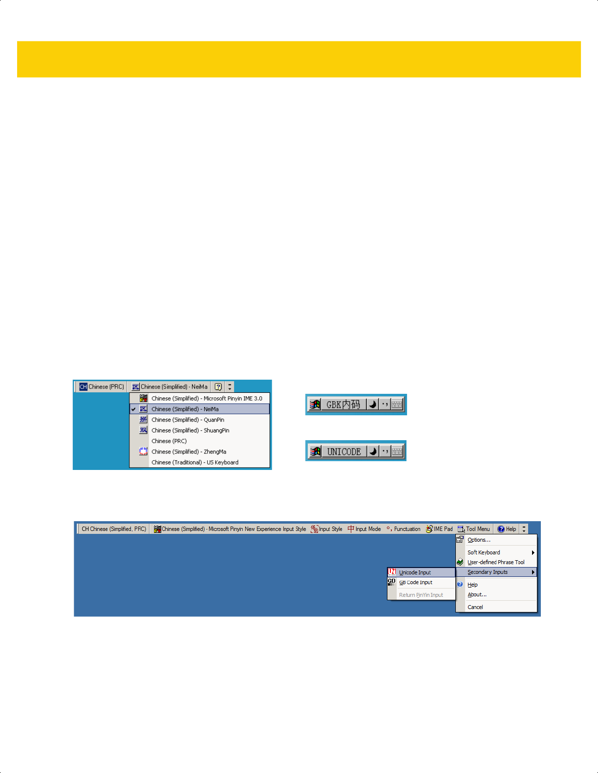
D - 6 DS2278 Digital Scanner Product Reference Guide
5. Under Supplemental Language Support, select the Install Files for East Asian Languages check box if not
already selected, and click Apply. This may require a Windows installation CD to install the required files. This
step ensures that the East Asian Languages (CJK) are available.
6. Under Text Services and Input Language, click Details.
7. Under Installed Services, click Add.
8. In the Add Input Language dialog box, choose the CJK input language and keyboard layout or Input Method
Editor (IME) to add.
9. Click OK twice. The language indicator appears in the system tray (at bottom right corner of the desktop by
default). To switch between input languages (keyboard languages) select the language indicator in the system
tray.
10. Select the language indicator in the system tray to select the desired country keyboard type.
11. Verify that the characters displayed on each country's keyboard appear.
Selecting the Simplified Chinese Input Method on the Host
To select the Simplified Chinese input method:
•
Select Unicode/GBK input on Windows XP: Chinese (Simplified) - NeiMa, then click the input bar to select
Unicode or GBK NeiMa input.
•
Select Unicode/GBK input on Windows7: Chinese (Simplified) - Microsoft Pinyin New Experience Input
Style, then select Tool Menu > Secondary Inputs > Unicode Input or GB Code Input.
Or
ds2278-prg-en.book Page 6
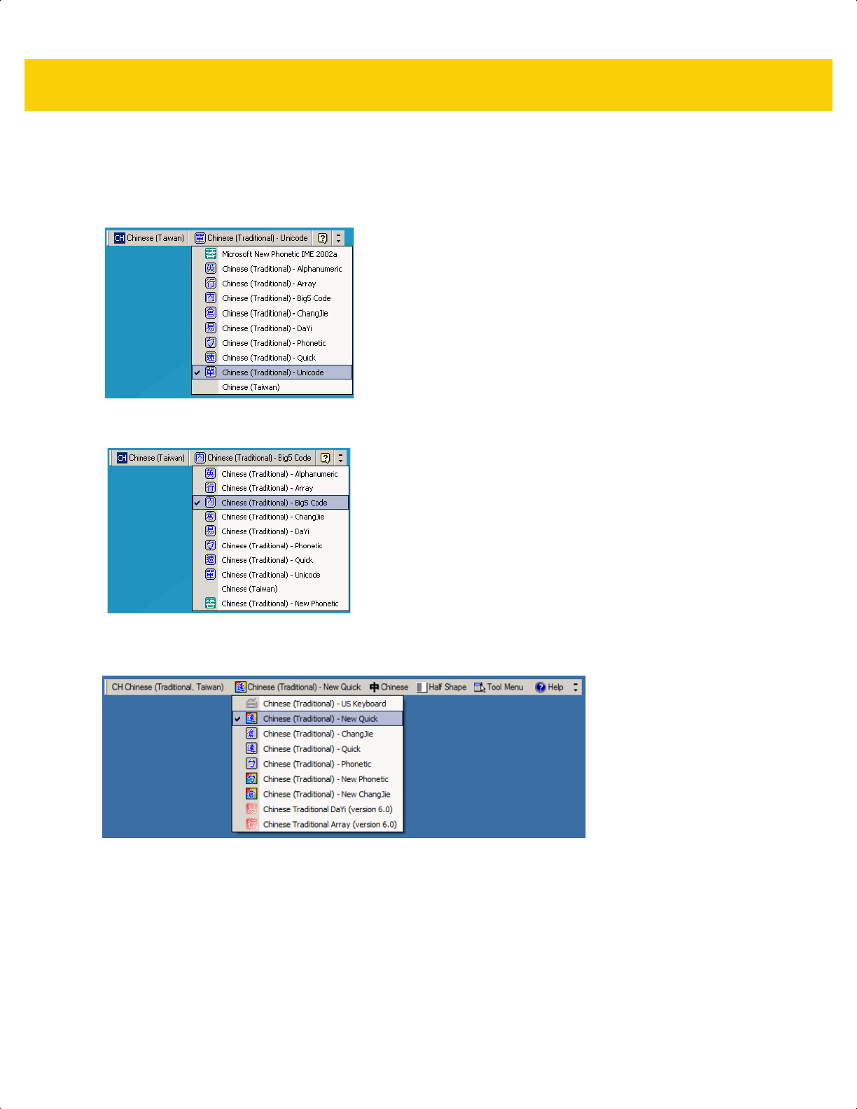
CJK Decode Control D - 7
Selecting the Traditional Chinese Input Method on the Host
To select the Traditional Chinese input method:
•
Select Unicode input on Windows XP: Chinese (Traditional) - Unicode
•
Select Big5 input on Windows XP: Chinese (Traditional) - Big5 Code
•
Select Unicode/Big5 input on Windows 7: Chinese (Traditional) - New Quick. This option support both
Unicode and Big5 input.
ds2278-prg-en.book Page 7

D - 8 DS2278 Digital Scanner Product Reference Guide
ds2278-prg-en.book Page 8

APPENDIX E PROGRAMMING
REFERENCE
Symbol Code Identifiers
Table E-1 Symbol Code Characters
Code Character Code Type
A UPC-A, UPC-E, UPC-E1, EAN-8, EAN-13
B Code 39, Code 32
C Codabar
D
Code 128, ISBT 128, ISBT 128 Concatenated
E Code 93
F Interleaved 2 of 5
G Discrete 2 of 5, or Discrete 2 of 5 IATA
H Code 11
J MSI
K GS1-128
L Bookland EAN
M Trioptic Code 39
N Coupon Code
R GS1 DataBar Family
S Matrix 2 of 5
T UCC Composite, TLC 39
U Chinese 2 of 5
ds2278-prg-en.book Page 1

E - 2 DS2278 Digital Scanner Product Reference Guide
V Korean 3 of 5
X
ISSN EAN
, PDF417, Macro PDF417, Micro PDF417
z Aztec, Aztec Rune
P00 Data Matrix
P01
QR Code, MicroQR
P02 Maxicode
P03 US Postnet
P04 US Planet
P05 Japan Postal
P06 UK Postal
P08 Netherlands KIX Code
P09 Australia Post
P0A USPS 4CB/One Code/Intelligent Mail
P0B UPU FICS Postal
P0C Mailmark
P0D Grid Matrix, Grid Matrix Inverse, Grid Matrix Mirror
P0G GS1 Data Matrix
P0H Han Xin
P0Q GS1 QR
P0X Signature Capture
Table E-1 Symbol Code Characters (Continued)
Code Character Code Type
ds2278-prg-en.book Page 2

Programming Reference E - 3
AIM Code Identifiers
Each AIM Code Identifier contains the three-character string ]cm where:
] = Flag Character (ASCII 93)
c = Code Character (see Table E-2)
m = Modifier Character (see Table E-3)
Table E-2 Aim Code Characters
Code Character Code Type
A Code 39, Code 39 Full ASCII, Code 32
C Code 128,
ISBT 128, ISBT 128 Concatenated, GS1-128,
Coupon (Code 128 portion)
d Data Matrix, GS1 Data Matrix
E UPC/EAN, Coupon (UPC portion)
e GS1 DataBar Family
F Codabar
G Code 93
H Code 11
h Han Xin
I Interleaved 2 of 5
L PDF417, Macro PDF417, Micro PDF417
L2 TLC 39
M MSI
Q
QR Code, MicroQR, GS1 QR
S Discrete 2 of 5, IATA 2 of 5
U Maxicode
z Aztec, Aztec Rune
X Bookland EAN,
ISSN EAN
, Trioptic Code 39,
Chinese 2 of 5,
Matrix 2 of 5, Korean 3 of 5,
US Postnet, US Planet, UK Postal, Japan
Postal, Australia Post, Netherlands KIX Code,
USPS 4CB/One Code/
Intelligent Mail, UPU FICS Postal, Mailmark, Signature Capture
]g Grid Matrix, Grid Matrix Inverse, Grid Matrix Mirror
ds2278-prg-en.book Page 3

E - 4 DS2278 Digital Scanner Product Reference Guide
The modifier character is the sum of the applicable option values based on Table E-3.
Table E-3 Modifier Characters
Code Type Option Value Option
Code 39 0 No check character or Full ASCII processing.
1 Reader has checked one check character.
3 Reader has checked and stripped check character.
4 Reader has performed Full ASCII character conversion.
5 Reader has performed Full ASCII character conversion and
checked one check character.
7 Reader has performed Full ASCII character conversion and
checked and stripped check character.
Example: A Full ASCII bar code with check character W, A+I+MI+DW, is transmitted as
]A7AIMID where 7 = (3+4).
Trioptic Code 39 0 No option specified at this time. Always transmit 0.
Example: A Trioptic bar code 412356 is transmitted as ]X0412356
Code 128 0 Standard data packet, no Function code 1 in first symbol position.
1 Function code 1 in first symbol character position.
2 Function code 1 in second symbol character position.
Example: A Code (EAN) 128 bar code with Function 1 character
FNC1
in the first
position, AIMID is transmitted as ]C1AIMID
I 2 of 5 0 No check digit processing.
1 Reader has validated check digit.
3 Reader has validated and stripped check digit.
Example: An I 2 of 5 bar code without check digit, 4123, is transmitted as ]I04123
Codabar 0 No check digit processing.
1 Reader has checked check digit.
3 Reader has stripped check digit before transmission.
Example: A Codabar bar code without check digit, 4123, is transmitted as ]F04123
Code 93 0 No options specified at this time. Always transmit 0.
Example: A Code 93 bar code 012345678905 is transmitted as ]G0012345678905
MSI 0 Check digits are sent.
1 No check digit is sent.
Example: An MSI bar code 4123, with a single check digit checked, is transmitted as
]M14123
ds2278-prg-en.book Page 4

Programming Reference E - 5
D 2 of 5 0 No options specified at this time. Always transmit 0.
Example: A D 2 of 5 bar code 4123, is transmitted as ]S04123
UPC/EAN 0 Standard data packet in full EAN format, i.e. 13 digits for UPC-A,
UPC-E, and EAN-13 (not including supplemental data).
1 Two digit supplemental data only.
2 Five digit supplemental data only.
3 Combined data packet comprising 13 digits from EAN-13, UPC-A
or UPC-E symbol and 2 or 5 digits from supplemental symbol.
4 EAN-8 data packet.
Example: A UPC-A bar code 012345678905 is transmitted as ]E00012345678905
Bookland EAN 0 No options specified at this time. Always transmit 0.
Example: A Bookland EAN bar code 123456789X is transmitted as ]X0123456789X
ISSN EAN 0 No options specified at this time. Always transmit 0.
Example: An ISSN EAN bar code 123456789X is transmitted as ]X0123456789X
Code 11 0 Single check digit
1 Two check digits
3 Check characters validated but not transmitted.
GS1 DataBar
Family
No option specified at this time. Always transmit 0. GS1 DataBar
Omnidirectional and GS1 DataBar Limited transmit with an
Application Identifier “01”.
Note: In GS1-128 emulation mode, GS1 DataBar is transmitted
using Code 128 rules (i.e., ]C1).
Example: A
GS1 DataBar Omnidirectional bar code 0110012345678902 is transmitted
as ]e00110012345678902.
Table E-3 Modifier Characters (Continued)
Code Type Option Value Option
ds2278-prg-en.book Page 5

E - 6 DS2278 Digital Scanner Product Reference Guide
EAN.UCC
Composites
(GS1 DataBar,
GS1-128,
2D portion of
UPC composite)
Native mode transmission.
Note: UPC portion of composite is transmitted using UPC rules.
0 Standard data packet.
1 Data packet containing the data following an encoded symbol
separator character.
2 Data packet containing the data following an escape mechanism
character. The data packet does not support the ECI protocol.
3 Data packet containing the data following an escape mechanism
character. The data packet supports the ECI protocol.
GS1-128 emulation
Note: UPC portion of composite is transmitted using UPC rules.
1 Data packet is a GS1-128 symbol (i.e., data is preceded with ]JC1).
PDF417,
Micro PDF417
0 Reader set to conform to protocol defined in 1994 PDF417
symbology specifications. Note: When this option is transmitted,
the receiver cannot reliably determine whether ECIs have been
invoked or whether data byte 92
DEC
has been doubled in
transmission.
1 Reader set to follow the ECI protocol (Extended Channel
Interpretation). All data characters 92
DEC
are doubled.
2 Reader set for Basic Channel operation (no escape character
transmission protocol). Data characters 92
DEC
are not doubled.
Note: When decoders are set to this mode, unbuffered Macro
symbols and symbols requiring the decoder to convey ECI escape
sequences cannot be transmitted.
3 The bar code contains a GS1-128 symbol, and the first codeword
is 903-907, 912, 914, 915.
4 The bar code contains a GS1-128 symbol, and the first codeword
is in the range 908-909.
5 The bar code contains a GS1-128 symbol, and the first codeword
is in the range 910-911.
Example: A PDF417 bar code ABCD, with no transmission protocol enabled, is
transmitted as ]L2ABCD.
Table E-3 Modifier Characters (Continued)
Code Type Option Value Option
ds2278-prg-en.book Page 6

Programming Reference E - 7
Data Matrix 0 ECC 000-140, not supported.
1 ECC 200.
2 ECC 200, FNC1 in first or fifth position.
3 ECC 200, FNC1 in second or sixth position.
4 ECC 200, ECI protocol implemented.
5 ECC 200, FNC1 in first or fifth position, ECI protocol implemented.
6 ECC 200, FNC1 in second or sixth position, ECI protocol
implemented.
MaxiCode 0 Symbol in Mode 4 or 5.
1 Symbol in Mode 2 or 3.
2 Symbol in Mode 4 or 5, ECI protocol implemented.
3 Symbol in Mode 2 or 3, ECI protocol implemented in secondary
message.
QR Code 0 Model 1 symbol.
1
Model 2 / MicroQR symbol
, ECI protocol not implemented.
2 Model 2 symbol, ECI protocol implemented.
3 Model 2 symbol, ECI protocol not implemented, FNC1 implied in
first position.
4 Model 2 symbol, ECI protocol implemented, FNC1 implied in first
position.
5 Model 2 symbol, ECI protocol not implemented, FNC1 implied in
second position.
6 Model 2 symbol, ECI protocol implemented, FNC1 implied in
second position.
Aztec
0 Aztec symbol.
C Aztec Rune symbol.
Han Xin
0 Generic data, no special features are set. The transmitted data does
not follow the AIM ECI protocol.
1 ECI protocol enabled. There is at least one ECI mode encoded.
Transmitted data must follow the AIM ECI protocol.
Grid Matrix, Grid
Matrix Inverse,
Grid Matrix Mirror
0 No options specified at this time. Always transmit 0.
Table E-3 Modifier Characters (Continued)
Code Type Option Value Option
ds2278-prg-en.book Page 7

E - 8 DS2278 Digital Scanner Product Reference Guide
ds2278-prg-en.book Page 8


F - 2 DS2278 Digital Scanner Product Reference Guide
UPC/EAN (continued)
UPC-A with 5-digit Add-on
UPC-E
UPC-E with 2-digit Add-on
0 12345 67890
98765
0 425261 4
0 425261
98
ds2278-prg-en.book Page 2

Sample Bar Codes F - 3
UPC/EAN (continued)
UPC-E with 5-digit Add-on
EAN-8
EAN-13, 100%
0 425261
87654
3 4 5 6 7 8 9 0 1 2 3 4 0
ds2278-prg-en.book Page 3

F - 4 DS2278 Digital Scanner Product Reference Guide
UPC/EAN (continued)
EAN-13 with 2-digit Add-on
EAN-13 with 5-digit Add-on
3 456789 012340
12
3 456789 012340
54321
ds2278-prg-en.book Page 4

Sample Bar Codes F - 5
Code 128
GS1-128
Code 39
1 2 3 4 5 6 7 8 9 0
(01)94019097685457(13)170119(30)17
123ABC
ds2278-prg-en.book Page 5
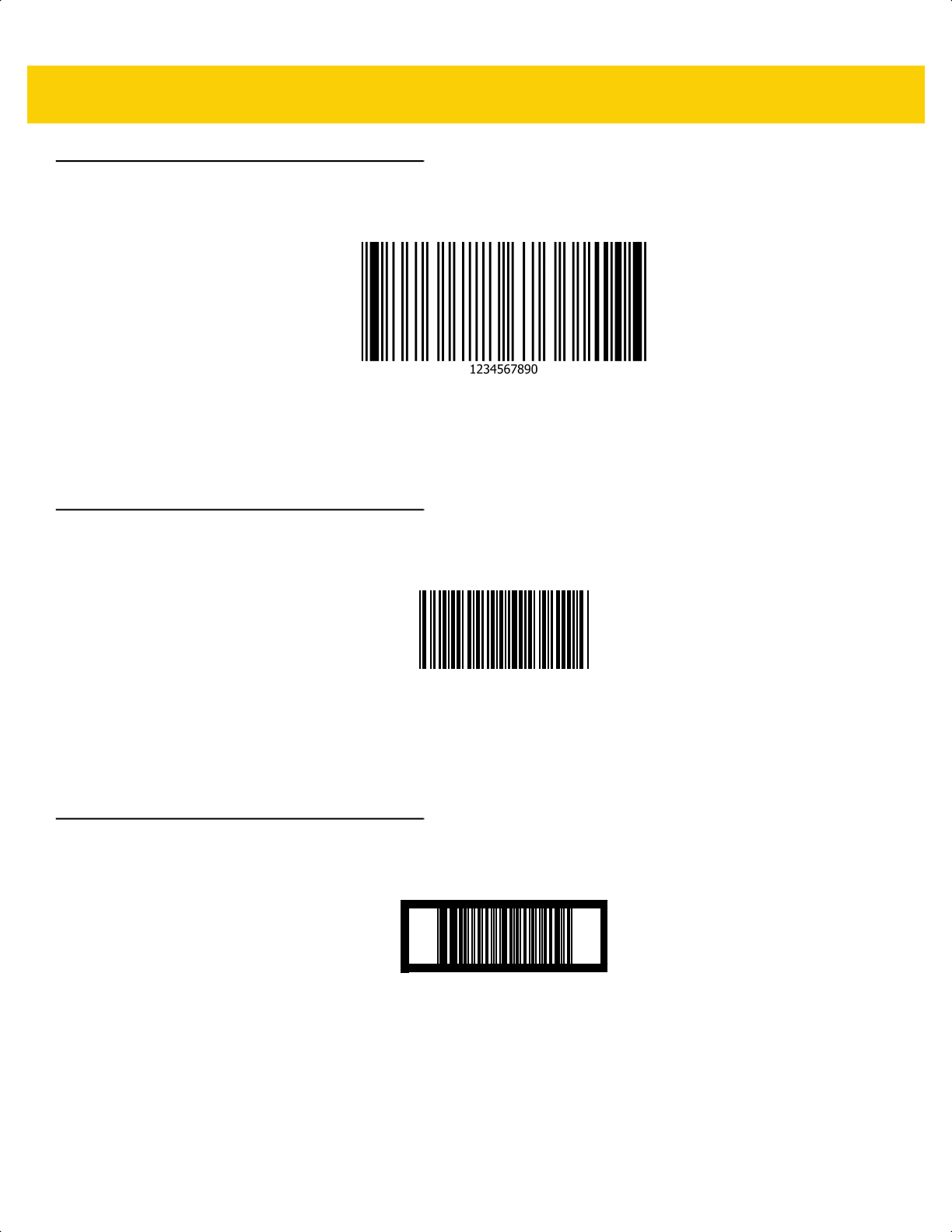
F - 6 DS2278 Digital Scanner Product Reference Guide
Code 93
Code 11 with 2 Check Digits
Interleaved 2 of 5
2468101275
12345678901231
ds2278-prg-en.book Page 6
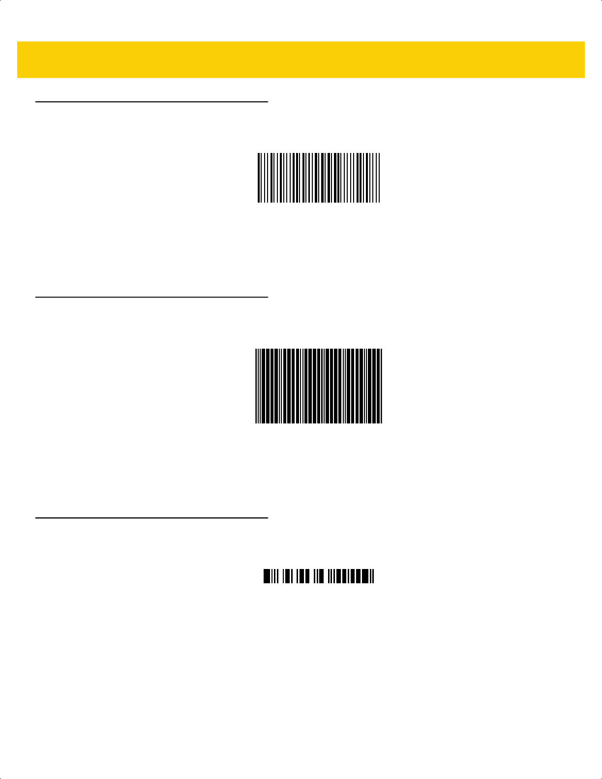
Sample Bar Codes F - 7
MSI with 2 Check Digits
Chinese 2 of 5
Matrix 2 of 5
123455834
45454545454
223344
ds2278-prg-en.book Page 7

F - 8 DS2278 Digital Scanner Product Reference Guide
Korean 3 of 5
GS1 DataBar
GS1 DataBar Omnidirectional (formerly GS1 DataBar-14)
7612341562341
GS1 DataBar Truncated
1400230
(01)00614141999996
ds2278-prg-en.book Page 8

Sample Bar Codes F - 9
GS1 DataBar (continued)
GS1 DataBar Stacked
GS1 DataBar Stacked Omnidirectional
GS1 DataBar Limited
ds2278-prg-en.book Page 9

F - 10 DS2278 Digital Scanner Product Reference Guide
GS1 DataBar (continued)
GS1 DataBar Expanded
GS1 DataBar Expanded Stacked
ds2278-prg-en.book Page 10
Sample Bar Codes F - 11
2D Symbologies
PDF417
Data Matrix
GS1 Data Matrix
ds2278-prg-en.book Page 11
F - 12 DS2278 Digital Scanner Product Reference Guide
2D Symbologies (continued)
Maxicode
QR Code
GS1 QR
ds2278-prg-en.book Page 12
Sample Bar Codes F - 13
2D Symbologies (continued)
MicroQR
Aztec
0123456789ABCDEFGHIJKLMNOPQRSTUVWXYZ0123456789ABCDEFGHIJKLMNOPQRSTUVWXYZ0123456789012345
6789ABCDEFGHIJKLMNOPQRSTUVWXYZ0123456789ABCDEFGHIJKLMNOPQRSTUVWXYZ0123456789
Grid Matrix
ds2278-prg-en.book Page 13

F - 14 DS2278 Digital Scanner Product Reference Guide
2D Symbologies (continued)
Han Xin
Postal Codes
US Postnet
UK Postal
ds2278-prg-en.book Page 14

Sample Bar Codes F - 15
Postal Codes (continued)
Japan Post
Australian Post
5008861
39549554
ds2278-prg-en.book Page 15

F - 16 DS2278 Digital Scanner Product Reference Guide
ds2278-prg-en.book Page 16

APPENDIX G NUMERIC BAR CODES
Numeric Bar Codes
For parameters requiring specific numeric values, scan the appropriately numbered bar code(s).
0
1
2
3
ds2278-prg-en.book Page 1

G - 2 DS2278 Digital Scanner Product Reference Guide
Numeric Bar Codes (continued)
4
5
6
7
8
9
ds2278-prg-en.book Page 2

Numeric Bar Codes G - 3
Cancel
To correct an error or change a selection, scan the bar code below.
Cancel
ds2278-prg-en.book Page 3

G - 4 DS2278 Digital Scanner Product Reference Guide
ds2278-prg-en.book Page 4

APPENDIX H ALPHAUMERIC BAR
CODES
Cancel
To correct an error or change a selection, scan the following bar code.
Cancel
ds2278-prg-en.book Page 1
H - 2 DS2278 Digital Scanner Product Reference Guide
Alphanumeric Bar Codes
Space
#
$
%
*
+
ds2278-prg-en.book Page 2

Alphaumeric Bar Codes H - 3
Alphanumeric Bar Codes (continued)
-
.
/
!
“
&
ds2278-prg-en.book Page 3

H - 4 DS2278 Digital Scanner Product Reference Guide
Alphanumeric Bar Codes (continued)
‘
(
)
:
;
<
ds2278-prg-en.book Page 4

Alphaumeric Bar Codes H - 5
Alphanumeric Bar Codes (continued)
=
>
?
@
[
\
ds2278-prg-en.book Page 5

H - 6 DS2278 Digital Scanner Product Reference Guide
Alphanumeric Bar Codes (continued)
]
^
_
`
ds2278-prg-en.book Page 6

Alphaumeric Bar Codes H - 7
Alphanumeric Bar Codes (continued
NOTE Do not confuse the following bar codes with those on the numeric keypad.
0
1
2
3
4
5
ds2278-prg-en.book Page 7

H - 8 DS2278 Digital Scanner Product Reference Guide
Alphanumeric Bar Codes (continued)
6
7
8
9
End of Message
Cancel
ds2278-prg-en.book Page 8

Alphaumeric Bar Codes H - 9
Alphanumeric Bar Codes (continued)
A
B
C
D
E
F
ds2278-prg-en.book Page 9

H - 10 DS2278 Digital Scanner Product Reference Guide
Alphanumeric Bar Codes (continued)
G
H
I
J
K
L
ds2278-prg-en.book Page 10
Alphaumeric Bar Codes H - 11
Alphanumeric Bar Codes (continued)
M
N
O
P
Q
R
ds2278-prg-en.book Page 11

H - 12 DS2278 Digital Scanner Product Reference Guide
Alphanumeric Bar Codes (continued)
S
T
U
V
W
X
ds2278-prg-en.book Page 12

Alphaumeric Bar Codes H - 13
Alphanumeric Bar Codes (continued)
Y
Z
a
b
c
d
ds2278-prg-en.book Page 13

H - 14 DS2278 Digital Scanner Product Reference Guide
Alphanumeric Bar Codes (continued)
e
f
g
h
i
j
ds2278-prg-en.book Page 14

Alphaumeric Bar Codes H - 15
Alphanumeric Bar Codes (continued)
k
l
m
n
o
p
ds2278-prg-en.book Page 15

H - 16 DS2278 Digital Scanner Product Reference Guide
Alphanumeric Bar Codes (continued)
q
r
s
t
u
v
ds2278-prg-en.book Page 16

Alphaumeric Bar Codes H - 17
Alphanumeric Bar Codes (continued)
w
x
y
z
{
|
ds2278-prg-en.book Page 17

H - 18 DS2278 Digital Scanner Product Reference Guide
Alphanumeric Bar Codes (continued)
}
~
ds2278-prg-en.book Page 18
APPENDIX I ASCII CHARACTER
SETS
NOTE For the Keyboard Wedge Interface, Code 39 Full ASCII interprets the bar code special character ($ + % /)
preceding a Code 39 character and assigns an ASCII character value to the pair. For example, if you
enable Code 39 Full ASCII and scan +B, it transmits as b, %J as ?, and %V as @.
Scanning ABC%I outputs the keystroke equivalent of ABC >.
Table I-1 ASCII Character Set
ASCII Value
(Prefix/Suffix
Value for RS-232)
Full ASCII Code 39
Encode Char
Keystroke
ASCII Character
(Applies to RS-232 Only)
1000 %U CTRL 2
NUL
1001 $A CTRL A
SOH
1002 $B CTRL B
STX
1003 $C CTRL C
ETX
1004 $D CTRL D
EOT
1005 $E CTRL E
ENQ
1006 $F CTRL F
ACK
1007 $G CTRL G
BELL
1008 $H CTRL H/BACKSPACE
1
BCKSPC
1009 $I CTRL I/HORIZONTAL TAB
1
HORIZ TAB
1010 $J CTRL J
LF/NW LN
1011 $K CTRL K
VT
1012 $L CTRL L
FF
1
The keystroke in bold transmits only if you enabled Function Key Mapping on page 8-15 or page
12-8.
Otherwise, the unbold keystroke transmits.
ds2278-prg-en.book Page 1

I - 2 DS2278 Digital Scanner Product Reference Guide
1013 $M CTRL M/ENTER
1
CR/ENTER
1014 $N CTRL N
SO
1015 $O CTRL O
SI
1016 $P CTRL P
DLE
1017 $Q CTRL Q
DC1/XON
1018 $R CTRL R
DC2
1019 $S CTRL S
DC3/XOFF
1020 $T CTRL T
DC4
1021 $U CTRL U
NAK
1022 $V CTRL V
SYN
1023 $W CTRL W
ETB
1024 $X CTRL X
CAN
1025 $Y CTRL Y
EM
1026 $Z CTRL Z
SUB
1027 %A CTRL [
ESC
1028 %B CTRL \
FS
1029 %C CTRL ]
GS
1030 %D CTRL 6
RS
1031 %E CTRL -
US
1032 Space Space
Space
1033 /A !
!
1034 /B “
"
1035 /C #
#
1036 /D $
$
1037 /E %
%
1038 /F &
&
1039 /G ‘
‘
Table I-1 ASCII Character Set (Continued)
ASCII Value
(Prefix/Suffix
Value for RS-232)
Full ASCII Code 39
Encode Char
Keystroke
ASCII Character
(Applies to RS-232 Only)
1
The keystroke in bold transmits only if you enabled Function Key Mapping on page 8-15 or page
12-8.
Otherwise, the unbold keystroke transmits.
ds2278-prg-en.book Page 2

ASCII Character Sets I - 3
1040 /H (
(
1041 /I )
)
1042 /J *
*
1043 /K +
+
1044 /L ,
,
1045 - -
-
1046 . .
.
1047 /o /
/
1048 0 0
0
1049 1 1
1
1050 2 2
2
1051 3 3
3
1052 4 4
4
1053 5 5
5
1054 6 6
6
1055 7 7
7
1056 8 8
8
1057 9 9
9
1058 /Z :
:
1059 %F ;
;
1060 %G <
<
1061 %H =
=
1062 %I >
>
1063 %J ?
?
1064 %V @
@
1065 A A
A
1066 B B
B
Table I-1 ASCII Character Set (Continued)
ASCII Value
(Prefix/Suffix
Value for RS-232)
Full ASCII Code 39
Encode Char
Keystroke
ASCII Character
(Applies to RS-232 Only)
1
The keystroke in bold transmits only if you enabled Function Key Mapping on page 8-15 or page
12-8.
Otherwise, the unbold keystroke transmits.
ds2278-prg-en.book Page 3

I - 4 DS2278 Digital Scanner Product Reference Guide
1067 C C
C
1068 D D
D
1069 E E
E
1070 F F
F
1071 G G
G
1072 H H
H
1073 I I
I
1074 J J
J
1075 K K
K
1076 L L
L
1077 M M
M
1078 N N
N
1079 O O
O
1080 P P
P
1081 Q Q
Q
1082 R R
R
1083 S S
S
1084 T T
T
1085 U U
U
1086 V V
V
1087 W W
W
1088 X X
X
1089 Y Y
Y
1090 Z Z
Z
1091 %K [
[
1092 %L \
\
1093 %M ]
]
Table I-1 ASCII Character Set (Continued)
ASCII Value
(Prefix/Suffix
Value for RS-232)
Full ASCII Code 39
Encode Char
Keystroke
ASCII Character
(Applies to RS-232 Only)
1
The keystroke in bold transmits only if you enabled Function Key Mapping on page 8-15 or page
12-8.
Otherwise, the unbold keystroke transmits.
ds2278-prg-en.book Page 4

ASCII Character Sets I - 5
1094 %N ^
^
1095 %O _
_
1096 %W ‘
`
1097 +A a
a
1098 +B b
b
1099 +C c
c
1100 +D d
d
1101 +E e
e
1102 +F f
f
1103 +G g
g
1104 +H h
h
1105 +I i
i
1106 +J j
j
1107 +K k
k
1108 +L l
l
1109 +M m
m
1110 +N n
n
1111 +O o
o
1112 +P p
p
1113 +Q q
q
1114 +R r
r
1115 +S s
s
1116 +T t
t
1117 +U u
u
1118 +V v
v
1119 +W w
w
1120 +X x
x
Table I-1 ASCII Character Set (Continued)
ASCII Value
(Prefix/Suffix
Value for RS-232)
Full ASCII Code 39
Encode Char
Keystroke
ASCII Character
(Applies to RS-232 Only)
1
The keystroke in bold transmits only if you enabled Function Key Mapping on page 8-15 or page
12-8.
Otherwise, the unbold keystroke transmits.
ds2278-prg-en.book Page 5
I - 6 DS2278 Digital Scanner Product Reference Guide
1121 +Y y
y
1122 +Z z
z
1123 %P {
{
1124 %Q I
|
1125 %R }
}
1126 %S ~
~
1127
Undefined
7013
ENTER
Table I-2 ALT Key Character Set
ALT Keys Keystroke
2064 ALT 2
2065 ALT A
2066 ALT B
2067 ALT C
2068 ALT D
2069 ALT E
2070 ALT F
2071 ALT G
2072 ALT H
2073 ALT I
2074 ALT J
2075 ALT K
2076 ALT L
2077 ALT M
Table I-1 ASCII Character Set (Continued)
ASCII Value
(Prefix/Suffix
Value for RS-232)
Full ASCII Code 39
Encode Char
Keystroke
ASCII Character
(Applies to RS-232 Only)
1
The keystroke in bold transmits only if you enabled Function Key Mapping on page 8-15 or page
12-8.
Otherwise, the unbold keystroke transmits.
ds2278-prg-en.book Page 6

ASCII Character Sets I - 7
2078 ALT N
2079 ALT O
2080 ALT P
2081 ALT Q
2082 ALT R
2083 ALT S
2084 ALT T
2085 ALT U
2086 ALT V
2087 ALT W
2088 ALT X
2089 ALT Y
2090 ALT Z
Table I-3 GUI Key Character Set
GUI Key Keystroke
3000 Right Control Key
3048 GUI 0
3049 GUI 1
3050 GUI 2
3051 GUI 3
3052 GUI 4
3053 GUI 5
3054 GUI 6
3055 GUI 7
3056 GUI 8
3057 GUI 9
Note: GUI Shift Keys - The Apple™ iMac keyboard has an apple key on
either side of the space bar. Windows-based systems have a GUI key to
the left of the left ALT key, and to the right of the right ALT key.
Table I-2 ALT Key Character Set (Continued)
ALT Keys Keystroke
ds2278-prg-en.book Page 7

I - 8 DS2278 Digital Scanner Product Reference Guide
3065 GUI A
3066 GUI B
3067 GUI C
3068 GUI D
3069 GUI E
3070 GUI F
3071 GUI G
3072 GUI H
3073 GUI I
3074 GUI J
3075 GUI K
3076 GUI L
3077 GUI M
3078 GUI N
3079 GUI O
3080 GUI P
3081 GUI Q
3082 GUI R
3083 GUI S
3084 GUI T
3085 GUI U
3086 GUI V
3087 GUI W
3088 GUI X
3089 GUI Y
3090 GUI Z
Table I-3 GUI Key Character Set (Continued)
GUI Key Keystroke
Note: GUI Shift Keys - The Apple™ iMac keyboard has an apple key on
either side of the space bar. Windows-based systems have a GUI key to
the left of the left ALT key, and to the right of the right ALT key.
ds2278-prg-en.book Page 8

ASCII Character Sets I - 9
Table I-4 PF Key Character Set
PF Keys Keystroke
4001 PF 1
4002 PF 2
4003 PF 3
4004 PF 4
4005 PF 5
4006 PF 6
4007 PF 7
4008 PF 8
4009 PF 9
4010 PF 10
4011 PF 11
4012 PF 12
4013 PF 13
4014 PF 14
4015 PF 15
4016 PF 16
ds2278-prg-en.book Page 9

I - 10 DS2278 Digital Scanner Product Reference Guide
Table I-5 F key Character Set
F Keys Keystroke
5001 F 1
5002 F 2
5003 F 3
5004 F 4
5005 F 5
5006 F 6
5007 F 7
5008 F 8
5009 F 9
5010 F 10
5011 F 11
5012 F 12
5013 F 13
5014 F 14
5015 F 15
5016 F 16
5017 F 17
5018 F 18
5019 F 19
5020 F 20
5021 F 21
5022 F 22
5023 F 23
5024 F 24
ds2278-prg-en.book Page 10

ASCII Character Sets I - 11
Table I-6 Numeric Key Character Set
Numeric Keypad Keystroke
6042 *
6043 +
6044 Undefined
6045 -
6046 .
6047 /
6048 0
6049 1
6050 2
6051 3
6052 4
6053 5
6054 6
6055 7
6056 8
6057 9
6058 Enter
6059 Num Lock
ds2278-prg-en.book Page 11

I - 12 DS2278 Digital Scanner Product Reference Guide
Table I-7 Extended Key Character Set
Extended Keypad Keystroke
7001 Break
7002 Delete
7003 Pg Up
7004 End
7005 Pg Dn
7006 Pause
7007 Scroll Lock
7008 Backspace
7009 Tab
7010 Print Screen
7011 Insert
7012 Home
7013 Enter
7014 Escape
7015 Up Arrow
7016 Dn Arrow
7017 Left Arrow
7018 Right Arrow
ds2278-prg-en.book Page 12

APPENDIX J COMMUNICATION
PROTOCOL
FUNCTIONALITY
Functionality Supported via Communication (Cable) Interface
Table J-1 lists supported scanner functionality by communication protocol.
Table J-1 Communication Interface Functionality
Communication Interfaces
Functionality
Data
Transmission
Remote
Management
Image and Video
Transmission
USB
HID Keyboard Emulation Supported Not Available Not Available
Simple COM Port Emulation Not Available Not Available Not Available
SSI over CDC COM Port Emulation Supported Supported Not Available
IBM Table-Top USB Supported Supported Not Available
IBM Hand-Held USB Supported Supported Not Available
USB OPOS Hand-Held Supported Supported Not Available
Symbol Native API (SNAPI) without
Imaging Interface
Supported Supported Not Available
Symbol Native API (SNAPI) with Imaging
Interface
Supported Supported Not Available
RS-232
Standard RS-232 Supported Not Available Not Available
ICL RS-232 Supported Not Available Not Available
Fujitsu RS-232 Supported Not Available Not Available
Wincor-Nixdorf RS-232 Mode A Supported Not Available Not Available
Wincor-Nixdorf RS-232 Mode B Supported Not Available Not Available
ds2278-prg-en.book Page 1

J - 2 DS2278 Digital Scanner Product Reference Guide
Olivetti ORS4500 Supported Not Available Not Available
Omron Supported Not Available Not Available
CUTE Supported Not Available Not Available
OPOS/JPOS Supported Not Available Not Available
SSI Supported Supported Not Available
IBM 4690
Hand-Held Scanner Emulation (Port 9B) Supported Not Available Not Available
Table-Top Scanner Emulation (Port 17) Supported Supported Not Available
Non-IBM Scanner Emulation (Port 5B) Supported Supported Not Available
Keyboard Wedge
IBM PC/AT & IBM PC Compatibles Supported Not Available Not Available
IBM AT Notebook Supported Not Available Not Available
Table J-1 Communication Interface Functionality (Continued)
Communication Interfaces
Functionality
Data
Transmission
Remote
Management
Image and Video
Transmission
ds2278-prg-en.book Page 2

APPENDIX K SIGNATURE CAPTURE
CODE
Introduction
CapCode, a signature capture code, is a special pattern that encloses a signature area on a document and allows
a scanner to capture a signature.
There are several accepted patterns that allow automatic identification of different signatures on the same form.
For example, on the federal tax return 1040 form there are three signature areas, one each for two joint filers, and
one for a professional preparer. By using different patterns, a program can correctly identify all three, so they can
be captured in any sequence and still be identified correctly.
Code Structure
Signature Capture Area
A CapCode is printed as two identical patterns on either side of a signature capture box, as shown in Figure K-1.
Each pattern extends the full height of the signature capture box.
The box is optional, so you can omit it, replace it with a single baseline, or print a baseline with an "X" on top of it
towards the left, as is customarily done in the US to indicate a request for signature. However, if an "X" or other
markings are added in the signature box area, these are captured with the signature.
Figure K-1 CapCode
NOTE Although the DS2278 digital scanner supports signature capture, the quality of the image is not
guaranteed. If the image does not meet your needs it is recommended that you upgrade to a DS8178
scanner.
]
tÇx WÉ
x
ds2278-prg-en.book Page 1
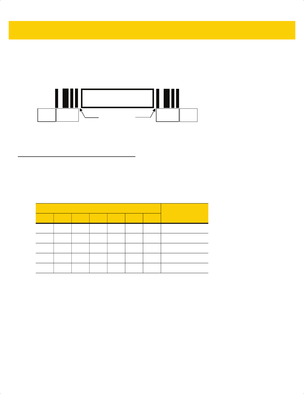
K - 2 DS2278 Digital Scanner Product Reference Guide
CapCode Pattern Structure
A CapCode pattern structure consists of a start pattern followed by a separator space, a signature capture box, a
second separator space, and then a stop pattern. Assuming that X is the dimension of the thinnest element, the
start and stop patterns each contains 9X total width in 4 bars and 3 spaces. A 7X quiet zone is required to the left
and to the right of the CapCode pattern.
Figure K-2 CapCode Structure
The separator spaces on either side of the signature capture box can be between 1X and 3X wide.
Start / Stop Patterns
Table K-1 lists the accepted start / stop patterns. The bar and space widths are expressed as multiples of X. You
must use the same pattern on either side of a signature capture box. The type value is reported with the captured
signature to indicate the purpose of the signature captured.
Capture Box
Separator Spaces
Start
Stop
Quiet
Zone
Quiet
Zone
Table K-1 Start / Stop Pattern Definitions
Bar/Space Patterns
Type
B S B S B S B
1 1 2 2 1 1 1 2
1 2 2 1 1 1 1 5
2 1 1 2 1 1 1 7
2 2 1 1 1 1 1 8
3 1 1 1 1 1 1 9
ds2278-prg-en.book Page 2
Signature Capture Code K - 3
Table K-2 lists selectable parameters used to generate the image of the captured signature.
BMP format does not use compression, JPEG and TIFF formats do.
Dimensions
The size of the signature capture box is determined by the height and separation of the start and stop patterns. The
line width of the signature capture box is insignificant.
The thinnest element width, referred to here as X, is nominally 10 mils (1 mil = 0.0254 mm). Select this as an exact
multiple of the pixel pitch of the printer used. For example, when using a 203 DPI (dots-per-inch) printer and
printing 2 dots per module, the resulting X dimension is 9.85 mils.
Data Format
The decoder output is formatted according to Table K-3. Zebra decoders allow different user options to output or
inhibit bar code type. Selecting "Symbol ID" as the bar code type for output identifies the CapCode with letter "i".
Table K-2 User Defined CapCode Parameters
Parameter Defined
Width Number of pixels
Height Number of pixels
Format JPEG, BMP, TIFF
JPEG quality 1 (most compression) to 100 (best quality)
Bits Per Pixel
(not applicable to JPEG format)
1 (2 levels)
4 (16 levels)
8 (256 levels)
Table K-3 Data Format
File Format
(1 byte)
Type (1 byte)
Image Size
(4 bytes, BIG Endian)
Image Data
JPEG - 1
BMP - 3
TIFF - 4
See
Table K-1
, last
column
(Same bytes as in a
data file)
ds2278-prg-en.book Page 3

K - 4 DS2278 Digital Scanner Product Reference Guide
Additional Capabilities
Regardless of how the signature is captured, the output signature image is de-skewed and right-side up.
A scanner that captures signatures automatically determines whether it is scanning a signature or a bar code. You
can disable the signature capturing capability in a decoder.
Signature Boxes
Figure K-3 illustrates the five acceptable signature boxes:
Figure K-3 Acceptable Signature Boxes
Type 2:
Type 5:
Type 7:
Type 8:
Type 9:
ds2278-prg-en.book Page 4

APPENDIX L NON-PARAMETER
ATTRIBUTES
Introduction
This appendix defines non-parameter attributes.
Attributes
Model Number
Attribute #533
Model number of the scanner. This electronic output matches the printout on the physical device label, for example
DS2278-SR00007ZZWW.
Type S
Size (Bytes) 18
User Mode Access R
Values Variable
Serial Number
Attribute #534
Unique serial number assigned in the manufacturing facility. This electronic output matches the printout on the
physical device label, for example M1J26F45V.
Type S
Size (Bytes) 16
User Mode Access R
Values Variable
ds2278-prg-en.book Page 1

L - 2 DS2278 Digital Scanner Product Reference Guide
Date of Manufacture
Attribute #535
Date of device manufacture assigned in the manufacturing facility. This electronic output matches the printout on
the physical device label, for example 30DEC16 (which reads the 30th of April 2014).
Type S
Size (Bytes) 7
User Mode Access R
Values Variable
Date of First Programming
Attribute #614
Date of first electronic programming represents the first time settings where electronically loaded to the scanner
either by 123Scan or via SMS, for example 30DEC16 (which reads the 30th of December 2016).
Type S
Size (Bytes) 7
User Mode Access R
Values Variable
Configuration Filename
Attribute #616
The name assigned to the configuration settings loaded electronically to the device either by 123Scan or via SMS.
To indicate the configuration settings loaded to the device were changed, the configuration filename changes to
Modified upon scanning any parameter bar code.
Type S
Size (Bytes) 17
User Mode Access RW
Values Variable
NOTE Scanning the Set Defaults bar code automatically changes the configuration filename to factory defaults.
ds2278-prg-en.book Page 2

Non-Parameter Attributes L - 3
Beeper/LED
Attribute #6000
Activates the beeper and/or LED.
Type X
Size (Bytes) N/A
User Mode Access W
Values:
Beep / LED Action Value
1 high short beep 0
2 high short beeps 1
3 high short beeps 2
4 high short beeps 3
5 high short beeps 4
1 low short beep 5
2 low short beeps 6
3 low short beeps 7
4 low short beeps 8
5 low short beeps 9
1 high long beep 10
2 high long beeps 11
3 high long beeps 12
4 high long beeps 13
5 high long beeps 14
1 low long beep 15
2 low long beeps 16
3 low long beeps 17
4 low long beeps 18
5 low long beeps 19
Fast warble beep 20
Slow warble beep 21
High-low beep 22
Low-high beep 23
High-low-high beep 24
Low-high-low beep 25
High-high-low-low beep 26
Green LED off 42
Green LED on 43
Red LED on 47
Red LED off 48
ds2278-prg-en.book Page 3

L - 4 DS2278 Digital Scanner Product Reference Guide
Parameter Defaults
Attribute #6001
This attribute restores all parameters to their factory defaults.
Type X
Size (Bytes) N/A
User Mode Access W
Values 0 = Restore Defaults
1 = Restore Factory Defaults
2 = Write Custom Defaults
Beep on Next Bootup
Attribute #6003
This attribute configures (enables or disables) beep on next boot up of scanner.
Type X
Size (Bytes) N/A
User Mode Access W
Values 0 = Disable beep on next bootup
1 = Enable beep on next bootup
Reboot
Attribute #6004
This attribute initiates a device reboot.
Type X
Size (Bytes) N/A
User Mode Access W
Values N/A
Host Trigger Session
Attribute #6005
This attribute triggers a decode session similar to manually depressing the scanner trigger button.
Type X
Size (Bytes) N/A
User Mode Access W
Values 1 = Start Host Trigger Session
0 = Stop Host Trigger Session
ds2278-prg-en.book Page 4

Non-Parameter Attributes L - 5
Firmware Version
Attribute #20004
The scanner's operating system version. For example, PAADES00-001-R00D0.
Type S
Size (Bytes) Variable
User Mode Access R
Values Variable
ImageKit Version
Attribute #20008
Identifies the 1D decode algorithms resident on the device, for example IMGKIT_7.03T01.
Type S
Size (Bytes) Variable
User Mode Access R
Values Variable
In Cradle Detect
Attribute #25000
Type Byte
Size (Bytes) 1
User Mode Access R
Values 0 - Out of cradle
1 - In cradle
Charging
Attribute #25002
Type Byte
Size (Bytes) 1
User Mode Access R
Values 0 - Not charging
1 - Charging
ds2278-prg-en.book Page 5

L - 6 DS2278 Digital Scanner Product Reference Guide
Battery Charge State
Attribute # 30042
Type Flag
Size (Bytes) 1
User Mode Access R
Values 0 - Not full
1 - Full
ds2278-prg-en.book Page 6

Appendix M FIRMWARE UPGRADES
USING iOS
Introduction
This appendix provides information about performing firmware upgrades using iOS. The Zebra Scanner Control
App for iOS provides an option to update firmware on your Bluetooth connected scanner. This application is
available in iOS App stores and the Zebra AppGallery.
Downloading Firmware Using the Zebra Scanner Control Application
To download firmware:
1. Install the Zebra Scanner Control application on your iOS device.
2. Create a folder on your Windows Desktop named Download.
3. Copy the scanner only plug-in (DS2278SR-SXXX-YY) into the Download folder as follows.
a. Load the 123Scan plug-in onto a Windows computer from: www.Zebra.com/123Scan.
b. From your Windows PC with 123Scan, access the scanner's (scanner only) plug-in (.scnplg file) from
C:\ProgramData\123Scan2\Plug-ins.
c. Copy the plug-in into the Download folder (created in Step 2).
4. Open iTunes and connect your iOS device to your computer via USB.
5. In iTunes, click the iOS device icon shown in Figure M-1.
NOTE In the plug-in name DS2278SR-SXXX-YY, XXX refers to the plug-in revision and YY refers to the build
number. The latest scanner only plug-in can be downloaded from 123Scan.
ds2278-prg-en.book Page 1
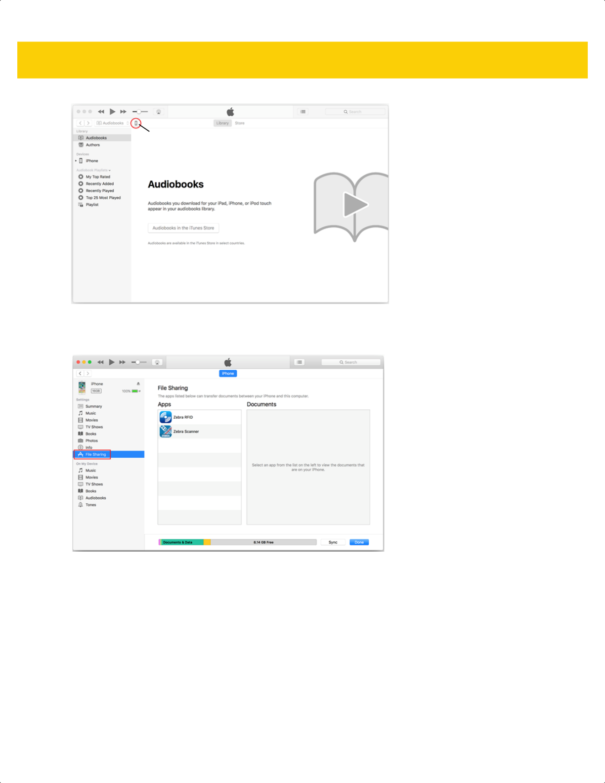
M - 2 DS2278 Digital Scanner Product Reference Guide
Figure M-1 iTunes - iOS Device Icon
6. Select File Sharing from the device menu (for your attached device).
Figure M-2 iTunes File Sharing Option
7. From the Apps list, click Zebra Scanner. Click the Download folder on the right and press Delete on the
keyboard.
iOS Device Icon
ds2278-prg-en.book Page 2
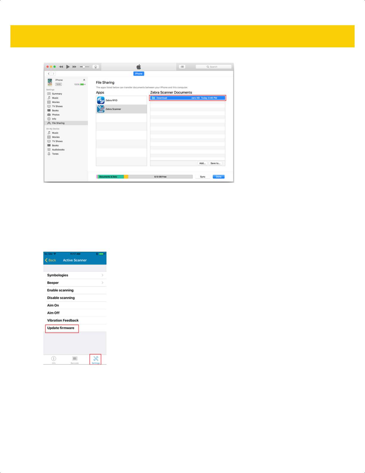
FIRMWARE UPGRADES USING iOS M - 3
Figure M-3 iTunes - Zebra Scanner Application/Zebra Scanner Documents
8. From the Windows Desktop, drag the Download folder into Zebra Scanner Documents.
9. Click Sync.
10. Open the Zebra Scanner Control application on the iOS device.
11. Connect the scanner to the iOS device and Zebra Scanner Control application.
12. Navigate to the Settings tab in the Zebra Scanner Control application, and tap Update Firmware.
Figure M-4 Settings - Update Firmware
13. Tap UPDATE FIRMWARE to start the process.
ds2278-prg-en.book Page 3

M - 4 DS2278 Digital Scanner Product Reference Guide
Figure M-5 Update Firmware
14. When the firmware update completes, the scanner automatically resets and installs the firmware.
15. The scanner sounds a beep and the LED illuminates green after the installation is complete.
ds2278-prg-en.book Page 4
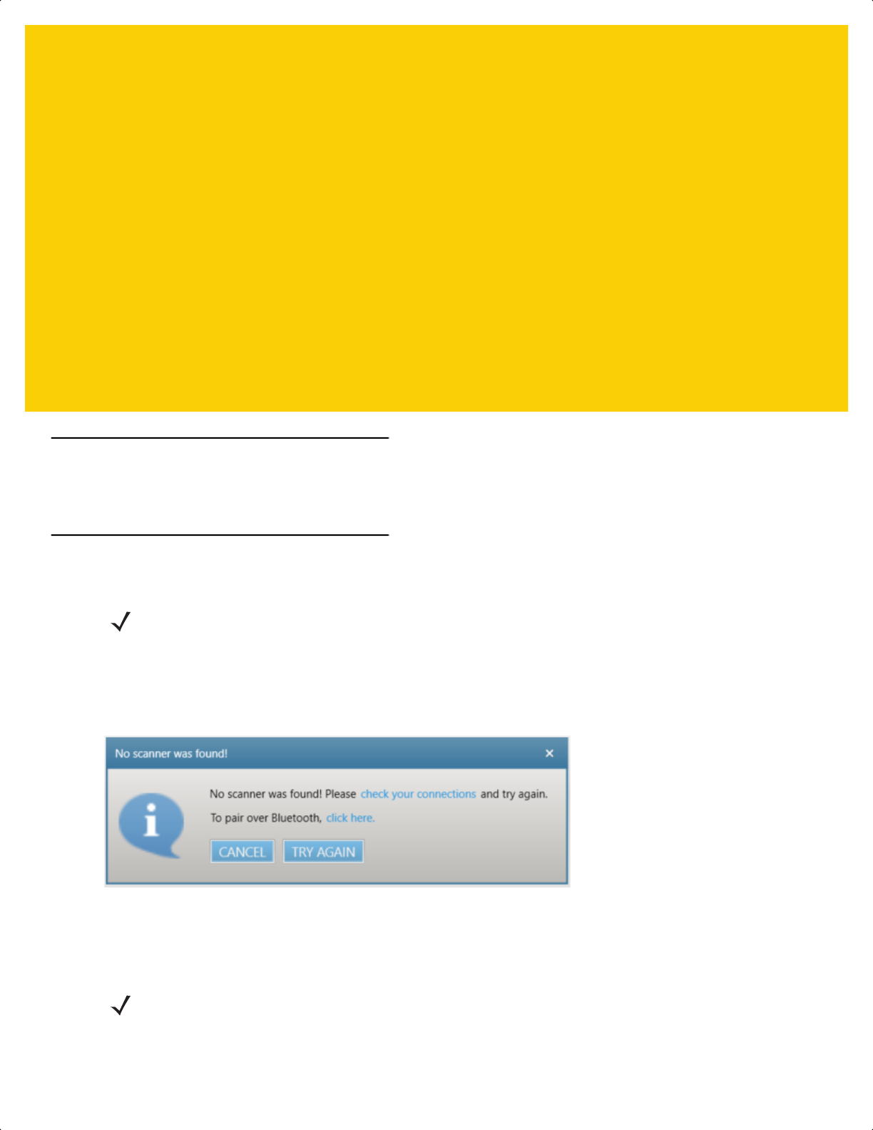
Appendix N UPGRADING OVER
BLUETOOTH WITHOUT
A CRADLE
Introduction
This appendix provides information about performing upgrades on the scanner without a cradle, using 123Scan.
Upgrading Without a Cradle
To upgrade a DS2278 scanner using 123Scan without a cradle:
1. From the 123Scan Start screen, select Update Scanner Firmware.
2. From the No scanner was found! dialog box, select click here to pair over Bluetooth.
Figure N-1 Pair Over Bluetooth Dialog
3. Scan the pairing bar code that displays to enable Bluetooth communication between the scanner and the host
PC. Once paired (can take 15 seconds), 123Scan guides the user through the remaining steps.
NOTE To accomplish this your PC must support Bluetooth communication.
NOTE The pairing bar code in Figure N-2 is a sample and not for scanning. Scan the actual pairing bar code that
displays in 123Scan.
ds2278-prg-en.book Page 1
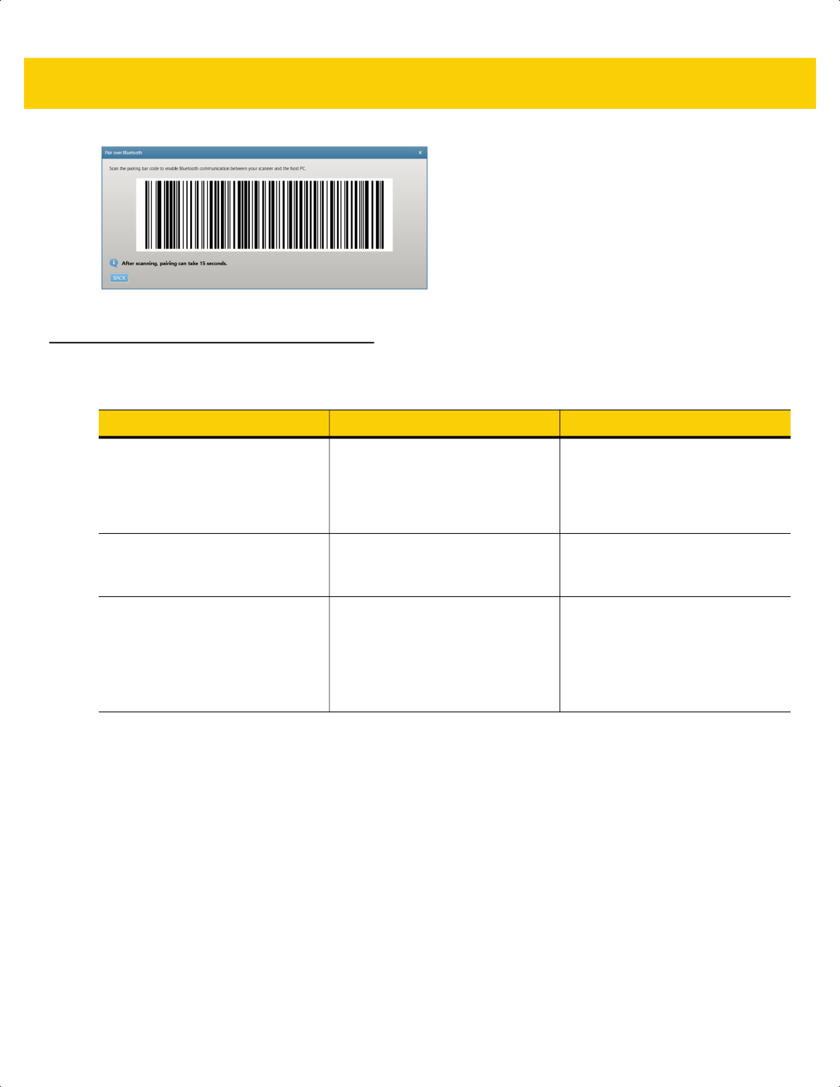
N - 2 DS2278 Digital Scanner Product Reference Guide
Figure N-2 Pairing Bar Code
Troubleshooting
Problem Possible Causes Possible Solutions
The Pair over Bluetooth dialog
box (Figure N-1 on page N-1) does
not display.
Scanner and/or cradle with a USB
cable is connected to the PC.
Remove the USB cable connected
to the PC from the scanner and/or
cradle. Re-select Update Scanner
Firmware from the 123Scan Start
screen.
Pairing bar code does not work
correctly.
Scanner was already paired directly
to the PC using the Windows
pairing process.
Select the Bluetooth icon in the PC
tray and remove the scanner from
the Bluetooth connection.
Windows displays the Add a
device pop up window (see Figure
N-3).
N/A This is a Windows display message
that cannot be suppressed.
Do not tap the Add a device
window and continue to follow the
123Scan prompts to complete the
process.
ds2278-prg-en.book Page 2
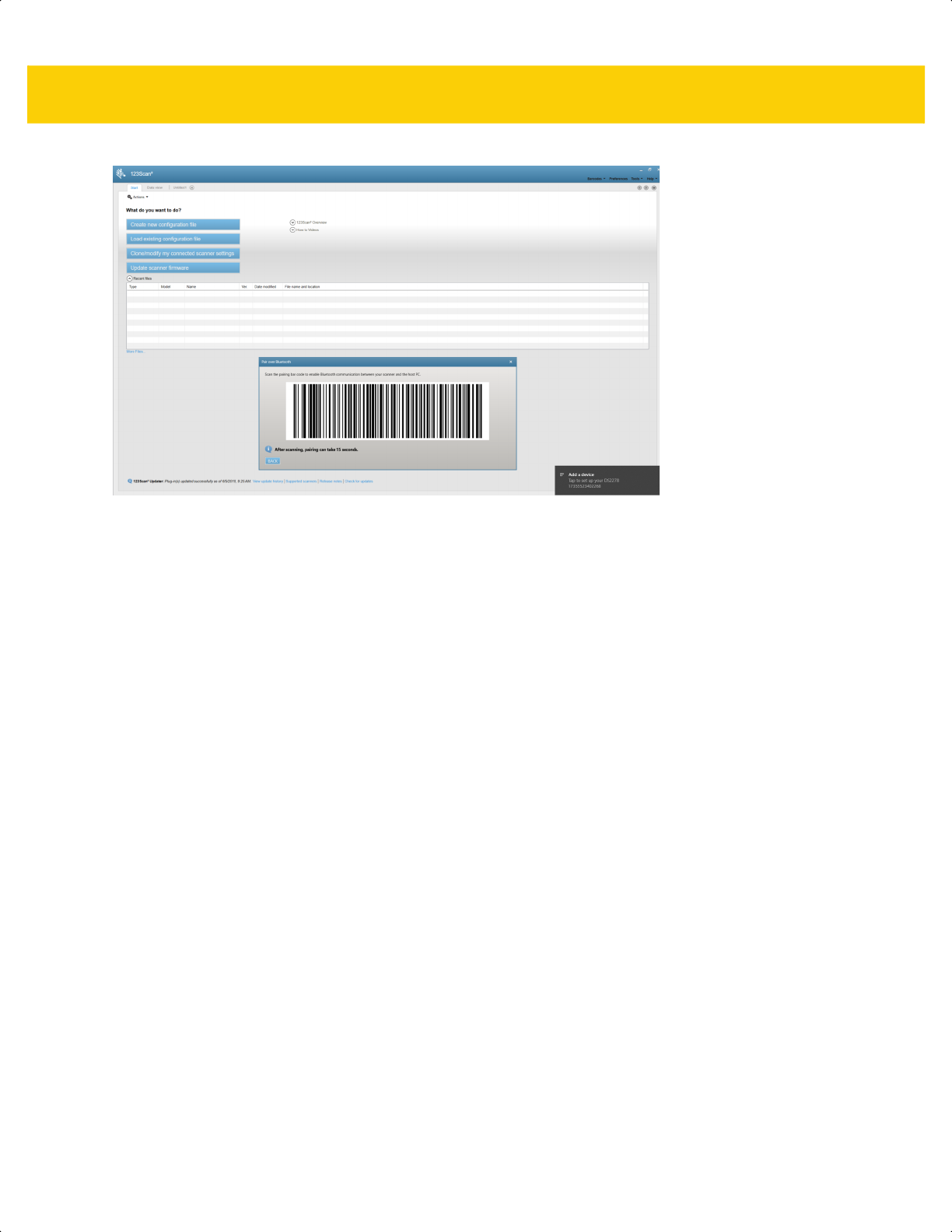
UPGRADING OVER BLUETOOTH WITHOUT A CRADLE N - 3
Figure N-3 Add a device Window
ds2278-prg-en.book Page 3

N - 4 DS2278 Digital Scanner Product Reference Guide
ds2278-prg-en.book Page 4

INDEX
Numerics
123Scan
communication . . . . . . . . . . . . . . . . . . . . . . . . . . 2-2
LED indications . . . . . . . . . . . . . . . . . . . . . . . . . . 3-5
options . . . . . . . . . . . . . . . . . . . . . . . . . . . . . . . . 2-1
requirements . . . . . . . . . . . . . . . . . . . . . . . . . . . . 2-2
software tools . . . . . . . . . . . . . . . . . . . . . . . . . . . 2-3
videos . . . . . . . . . . . . . . . . . . . . . . . . . . . . . . . . . 2-2
2D bar codes
aztec . . . . . . . . . . . . . . . . . . . . . . . . . . . . . . . . 13-93
aztec inverse . . . . . . . . . . . . . . . . . . . . . . . . . . 13-93
code 128 emulation . . . . . . . . . . . . . . . . . . . . . 13-85
data matrix . . . . . . . . . . . . . . . . . . . . . . . . . . . 13-86
data matrix inverse . . . . . . . . . . . . . . . . . . . . . 13-87
data matrix mirror images . . . . . . . . . . . . . . . . 13-88
dotcode erasure limit . . . . . . . . . . . . . . . . . . . 13-100
grid matrix . . . . . . . . . . . . . . . . . . . . . . . . . . . . 13-95
grid matrix inverse . . . . . . . . . . . . . . . . . . . . . . 13-95
grid matrix mirror . . . . . . . . . . . . . . . . . . . . . . . 13-96
GS1 data matrix . . . . . . . . . . . . . . . . . . . . . . . 13-86
GS1 QR . . . . . . . . . . . . . . . . . . . . . . . . . . . . . 13-90
han xin . . . . . . . . . . . . . . . . . . . . . . . . . . . . . . 13-94
han xin inverse . . . . . . . . . . . . . . . . . . . . . . . . 13-94
linked QR . . . . . . . . . . . . . . . . . . . . . . . . . . . . 13-92
maxicode . . . . . . . . . . . . . . . . . . . . . . . . . . . . . 13-89
microPDF417 . . . . . . . . . . . . . . . . . . . . . . . . . 13-84
microQR . . . . . . . . . . . . . . . . . . . . . . . . . . . . . 13-90
PDF417 . . . . . . . . . . . . . . . . . . . . . . . . . . . . . . 13-84
QR code . . . . . . . . . . . . . . . . . . . . . . . . . . . . . 13-89
A
accessories . . . . . . . . . . . . . . . . . . . . . . . . . . . . . . . 1-10
interface cable . . . . . . . . . . . . . . . . . . . . . . . . . . 1-10
power supply . . . . . . . . . . . . . . . . . . . . . . . . . . . 1-10
shielded cables . . . . . . . . . . . . . . . . . . . . . . . . . . 8-2
ADF
invalid rule . . . . . . . . . . . . . . . . . . . . . . . . . . . . . 4-5
transmit error . . . . . . . . . . . . . . . . . . . . . . . . . . . 4-5
ADF programming indicators . . . . . . . . . . . . . . . . . . 3-3
advanced data formatting . . . . . . . . . . . . . . . . . . . . . 4-5
aiming
orientation . . . . . . . . . . . . . . . . . . . . . . . . . . . . . . 3-8
aiming options
hand-held decode aiming pattern . . . . . . . . . . . 5-19
aiming pattern
enabling . . . . . . . . . . . . . . . . . . . . . . . . . . . . . . 5-19
ASCII values
keyboard wedge . . . . . . . . . . . . . . . . . . . . . . . 12-10
RS-232 . . . . . . . . . . . . . . . . . . . . . . . . . . . . . . 10-18
attributes, non-parameter
battery charge state . . . . . . . . . . . . . . . . . . . . . . L-6
beep on next bootup . . . . . . . . . . . . . . . . . . . . . . L-4
charging . . . . . . . . . . . . . . . . . . . . . . . . . . . . . . . L-5
configuration filename . . . . . . . . . . . . . . . . . . . . L-2
date of first programming . . . . . . . . . . . . . . . . . . L-2
date of manufacture . . . . . . . . . . . . . . . . . . . . . . L-2
firmware version . . . . . . . . . . . . . . . . . . . . . . . . . L-5
host trigger session . . . . . . . . . . . . . . . . . . . . . . L-4
imagekit version . . . . . . . . . . . . . . . . . . . . . . . . . L-5
in cradle detect . . . . . . . . . . . . . . . . . . . . . . . . . . L-5
model number . . . . . . . . . . . . . . . . . . . . . . . . . . . L-1
parameter defaults . . . . . . . . . . . . . . . . . . . . . . . L-4
reboot . . . . . . . . . . . . . . . . . . . . . . . . . . . . . . . . . L-4
serial number . . . . . . . . . . . . . . . . . . . . . . . . . . . L-1
auto-reconnect . . . . . . . . . . . . . . . . . . . 6-23, 6-27, 6-29
aztec bar codes
sample . . . . . . . . . . . . . . . . . . . . . . . . . . . . . . . F-13
B
bar code defaults
radio communications . . . . . . . . . . . . . . . . . . . . . 6-2
ds2278-prg-en.book Page 1

Index - 2 DS2278 Digital Scanner Product Reference Guide
bar codes
Australia post . . . . . . . . . . . . . . . . . . . . . . . . 13-105
Australia post format . . . . . . . . . . . . . . . . . . . 13-106
auto-reconnect in Bluetooth keyboard emulation (HID
peripheral) mode . . . . . . . . . . . . . . . . . 6-25
auto-reconnect interval . . . . . . . . . . . . . . . . . . . 6-23
aztec . . . . . . . . . . . . . . . . . . . . . . . . . . . . . . . . 13-93
aztec inverse . . . . . . . . . . . . . . . . . . . . . . . . . . 13-93
batch mode . . . . . . . . . . . . . . . . . . . . . . . .6-32, 6-34
battery preservation mode . . . . . . . . . . . . . . . . 5-15
battery shut off . . . . . . . . . . . . . . . . . . . . . . . . . . 1-7
beep after good decode . . . . . . . . . . . . . . . . . . . 5-6
beep on insertion . . . . . . . . . . . . . . . . . . . . . . . 6-26
beeper duration . . . . . . . . . . . . . . . . . . . . . . . . . . 5-9
beeper tone . . . . . . . . . . . . . . . . . . . . . . . . . . . . . 5-8
beeper volume . . . . . . . . . . . . . . . . . . . . . . . . . . 5-7
Bluetooth friendly name . . . . . . . . . . . . . . . . . . 6-10
Bluetooth technology support . . . . . . . . . . . . . . 6-16
bookland EAN . . . . . . . . . . . . . . . . . . . . . . . . . 13-11
bookland ISBN . . . . . . . . . . . . . . . . . . . . . . . . 13-12
cancel . . . . . . . . . . . . . . . . . . . . . . . . . . . . . G-3, H-1
Chinese 2 of 5 . . . . . . . . . . . . . . . . . . . . . . . . . 13-66
codabar . . . . . . . . . . . . . . . . . . . . . . . . . . . . . . 13-57
codabar CLSI editing . . . . . . . . . . . . . . . . . . . 13-59
codabar lengths . . . . . . . . . . . . . . . . . .13-57, 13-58
codabar NOTIS editing . . . . . . . . . . . . . . . . . . 13-59
codabar start and stop characters . . . . . . . . . 13-60
code 11 . . . . . . . . . . . . . . . . . . . . . . . . . . . . . . 13-44
code 11 check digit verification . . . . . . . . . . . . 13-46
code 11 lengths . . . . . . . . . . . . . . . . . . . . . . . . 13-44
code 128 . . . . . . . . . . . . . . . . . . . . . . . . . . . . . 13-27
code 128 emulation . . . . . . . . . . . . . . . . . . . . . 13-85
code 128 fnc4 . . . . . . . . . . . . . . . . . . . . . . . . . 13-32
code 128 lengths . . . . . . . . . . . . . . . . . . . . . . . 13-27
code 128 reduced quiet zone . . . . . . . . . . . . . 13-33
code 128 security level . . . . . . . . . . . . .13-32, 13-33
code 32 prefix . . . . . . . . . . . . . . . . . . . . . . . . . 13-35
code 39 . . . . . . . . . . . . . . . . . . . . . . . . . . . . . . 13-34
code 39 check digit verification . . . . . . . . . . . . 13-37
code 39 full ASCII . . . . . . . . . . . . . . . . . . . . . . 13-38
code 39 lengths . . . . . . . . . . . . . . . . . . .13-36, 13-37
code 39 reduced quiet zone . . . . . . . . . . . . . . 13-41
code 39 security level . . . . . . . . . . . . . .13-39, 13-40
code 39 transmit check digit . . . . . . . . . . . . . . 13-38
code 93 . . . . . . . . . . . . . . . . . . . . . . . . . . . . . . 13-41
code 93 lengths . . . . . . . . . . . . . . . . . . . . . . . . 13-42
composite beep mode . . . . . . . . . . . . . . . . . . . 13-83
composite CC-A/B . . . . . . . . . . . . . . . . . . . . . 13-80
composite CC-C . . . . . . . . . . . . . . . . . . . . . . . 13-79
composite inverse . . . . . . . . . . . . . . . . . . . . . . 13-81
composite TLC-39 . . . . . . . . . . . . . . . . . . . . . . 13-80
continuous bar code read . . . . . . . . . . . . . . . . . 5-21
convert code 39 to code 32 . . . . . . . . . . . . . . . 13-35
convert GS1 databar to UPC/EAN/JAN . . . . . 13-72
convert UPC-E to UPC-A . . . . . . . . . . . . . . . . 13-24
convert UPC-E1 to UPC-A . . . . . . . . . . . . . . . 13-24
country code page defaults . . . . . . . . . . . . . . . . . C-1
country code pages . . . . . . . . . . . . . . . . . . . . . . . C-5
country codes . . . . . . . . . . . . . . . . . . . . . . . . . . . B-2
data matrix . . . . . . . . . . . . . . . . . . . . . . . . . . . . 13-86
data matrix inverse . . . . . . . . . . . . . . . . . . . . . 13-87
data matrix mirror images . . . . . . . . . . . . . . . . 13-88
decode mirror images . . . . . . . . . . . . . . . . . . . . 5-24
decode session timeout . . . . . . . . . . . . . . . . . . . 5-22
direct decode indicator . . . . . . . . . . . . . . . . . . . 5-10
disable all code types . . . . . . . . . . . . . . . . . . . . 13-8
discrete 2 of 5 . . . . . . . . . . . . . . . . . . . . . . . . . 13-54
discrete 2 of 5 lengths . . . . . . . . . . . . . 13-55, 13-56
dotcode erasure limit . . . . . . . . . . . . . . . . . . . 13-100
EAN/JAN zero extend . . . . . . . . . . . . . . . . . . . 13-25
EAN-13 check digit . . . . . . . . . . . . . . . . . . . . . 13-20
EAN-13/JAN-13 . . . . . . . . . . . . . . . . . . . . . . . . 13-11
EAN-8 check digit . . . . . . . . . . . . . . . . . . . . . . 13-19
EAN-8/JAN-8 . . . . . . . . . . . . . . . . . . . . . . . . . . 13-10
eclevel . . . . . . . . . . . . . . . . . . . . . . . . . . . . . . . . 5-30
enable all code types . . . . . . . . . . . . . . . . . . . . . 13-8
enter . . . . . . . . . . . . . . . . . . . . . . . . . . . . . . . . . 5-31
escape characters . . . . . . . . . . . . . . . . . . . . . 13-101
event reporting
boot up event . . . . . . . . . . . . . . . . . . . . . . . 9-23
decode event . . . . . . . . . . . . . . . . . . . . . . . 9-22
parameter event . . . . . . . . . . . . . . . . . . . . . 9-23
febraban . . . . . . . . . . . . . . . . . . . . . . . . . . . . . 13-52
flush macro buffer/abort macro PDF entry . . 13-101
FN1 substitution values . . . . . . . . . . . . . . . . . . . 5-36
grid matrix . . . . . . . . . . . . . . . . . . . . . . . . . . . . 13-95
grid matrix inverse . . . . . . . . . . . . . . . . . . . . . . 13-95
grid matrix mirror . . . . . . . . . . . . . . . . . . . . . . . 13-96
GS1 data matrix . . . . . . . . . . . . . . . . . . . . . . . 13-86
GS1 databar bar codes . . . . . . . . . . . . . . . . . . 13-71
GS1 databar expanded . . . . . . . . . . . . . . . . . . 13-72
GS1 databar limited . . . . . . . . . . . . . . . . . . . . . 13-71
GS1 databar limited margin check . . . . . . . . . 13-73
GS1 databar omnidirectional . . . . . . . . . . . . . . 13-71
GS1 databar security level . . . . . . . . . . . . . . . 13-74
GS1 QR . . . . . . . . . . . . . . . . . . . . . . . . . . . . . . 13-90
GS1-128 . . . . . . . . . . . . . . . . . . . . . . . . . . . . . 13-28
GS1-128 emulation mode . . . . . . . . . . . . . . . . 13-83
han xin . . . . . . . . . . . . . . . . . . . . . . . . . . . . . . . 13-94
han xin inverse . . . . . . . . . . . . . . . . . . . . . . . . 13-94
hand-held decode aiming pattern . . . . . . 5-18, 5-19
hands-free mode . . . . . . . . . . . . . . . . . . . . . . . . 5-17
HID device conversion . . . . . . . . . . . . . . . . . . . . 1-6
I 2 of 5 check digit verification . . . . . . . . . . . . . 13-50
I 2 of 5 convert to EAN-13 . . . . . . . . . . . . . . . . 13-51
I 2 of 5 reduced quiet zone . . . . . . . . . . . . . . . 13-54
I 2 of 5 security level . . . . . . . . . . . . . . . . . . . . 13-53
I 2 of 5 transmit check digit . . . . . . . . . . . . . . . 13-51
ds2278-prg-en.book Page 2

Index - 3
IBM
bar code configuration directive . . . . . . . . . 11-6
beep directive . . . . . . . . . . . . . . . . . . . . . . . 11-5
convert unknown to code 39 . . . . . . . . . . . . 11-5
default table . . . . . . . . . . . . . . . . . . . . . . . . 11-3
IBM specification version . . . . . . . . . . . . . . 11-6
port address . . . . . . . . . . . . . . . . . . . . . . . . 11-4
illumination . . . . . . . . . . . . . . . . . . . . . . . . . . . . 5-26
illumination brightness . . . . . . . . . . . . . . . . . . . 5-26
intercharacter gap size . . . . . . . . . . . . . . . . . . 13-79
interleaved 2 of 5 . . . . . . . . . . . . . . . . . . . . . . 13-47
convert to EAN-13 . . . . . . . 13-51, 13-52, 13-53
interleaved 2 of 5 lengths . . . . . . . . . . .13-48, 13-49
inverse 1D . . . . . . . . . . . . . . . . . . . . . . . . . . . . 13-70
ISBT 128 . . . . . . . . . . . . . . . . . . . . . . . . . . . . . 13-29
ISBT concatenation . . . . . . . . . . . . . . . .13-30, 13-31
ISBT concatenation redundancy . . . . . . . . . . . 13-31
ISSN EAN . . . . . . . . . . . . . . . . . . . . . . . . . . . . 13-12
Japan postal . . . . . . . . . . . . . . . . . . . . . . . . . 13-104
keyboard wedge
alternate numeric keypad emulation . . . . . . 12-6
caps lock override . . . . . . . . . . . . . . . . . . . . 12-7
convert case . . . . . . . . . . . . . . . . . . . . . . . . 12-8
default table . . . . . . . . . . . . . . . . . . . . . . . . 12-3
host types . . . . . . . . . . . . . . . . . . . . . . . . . . 12-4
intra-keystroke delay . . . . . . . . . . . . . . . . . 12-5
keystroke delay . . . . . . . . . . . . . . . . . . . . . . 12-5
quick keypad emulation . . . . . . . . . . . . . . . 12-6
simulated caps lock . . . . . . . . . . . . . . . . . . 12-7
unknown characters . . . . . . . . . . . . . . . . . . 12-4
Korean 3 of 5 . . . . . . . . . . . . . . . . . . . . . . . . . 13-69
LED on good decode . . . . . . . . . . . . . . . . . . . . 5-10
linked QR . . . . . . . . . . . . . . . . . . . . . . . . . . . . 13-92
lock override . . . . . . . . . . . . . . . . . . . . . . . . . . . 6-27
low light enhancement . . . . . . . . . . . . . . . . . . . 5-28
low light scene detection . . . . . . . . . . . . . . . . . . 5-27
low power mode . . . . . . . . . . . . . . . . . . . . . . . . 5-11
mailmark . . . . . . . . . . . . . . . . . . . . . . . . . . . . 13-108
manufacturing information . . . . . . . . . . . . . . . . 5-39
matrix 2 of 5 . . . . . . . . . . . . . . . . . . . . . . . . . . 13-66
matrix 2 of 5 check digit . . . . . . . . . . . . . . . . . 13-68
matrix 2 of 5 lengths . . . . . . . . . . . . . . .13-67, 13-68
maxicode . . . . . . . . . . . . . . . . . . . . . . . . . . . . . 13-89
microPDF417 . . . . . . . . . . . . . . . . . . . . . . . . . 13-84
microQR . . . . . . . . . . . . . . . . . . . . . . . . . . . . . 13-90
mobile phone/display mode . . . . . . . . . . . . . . . 5-24
motion tolerance . . . . . . . . . . . . . . . . . . . . . . . . 5-28
MSI . . . . . . . . . . . . . . . . . . . . . . . . . . . . . . . . . 13-61
MSI check digit algorithm . . . . . . . . . . . . . . . . 13-65
MSI check digits . . . . . . . . . . . . . . . . . . . . . . . 13-64
MSI lengths . . . . . . . . . . . . . . . . . . . . . . . . . . . 13-62
MSI reduced quiet zone . . . . . . . . . . . . . . . . . 13-65
MSI transmit check digit . . . . . . . . . . . . . . . . . 13-64
Netherlands KIX code . . . . . . . . . . . . . . . . . . 13-107
numeric bar codes . . . . . . . . . . . . . . . . . . . . G-3, H-1
parameter scanning . . . . . . . . . . . . . . . . . . . . . . . 5-6
PDF prioritization . . . . . . . . . . . . . . . . . . . . . . . . 5-25
PDF prioritization timeout . . . . . . . . . . . . . . . . . 5-25
PDF417 . . . . . . . . . . . . . . . . . . . . . . . . . . . . . . 13-84
picklist mode . . . . . . . . . . . . . . . . . . . . . . . . . . . 5-20
pid type . . . . . . . . . . . . . . . . . . . . . . . . . . . . . . . 5-29
pid value . . . . . . . . . . . . . . . . . . . . . . . . . . . . . . 5-29
postal . . . . . . . . . . . . . . . . . . . . . . . . . . . . . . . 13-102
prefix/suffix values . . . . . . . . . . . . . . . . . . . . . . . 5-33
QR code . . . . . . . . . . . . . . . . . . . . . . . . . . . . . 13-89
quiet zone level . . . . . . . . . . . . . . . . . . . . . . . . 13-78
radio
Apple iOS virtual keyboard toggle . . . . . . . . 6-16
auto-reconnect . . . . . . . . . . . . . . . . . . . . . . 6-23
batch mode . . . . . . . . . . . . . . . . . . . . . . . . . 6-32
beep on . . . . . . . . . . . . . . . . . . . . . . . . . . . . 6-26
beep on insertion . . . . . . . . . . . . . . . . . . . . 6-26
bluetooth friendly name . . . . . . . . . . . . . . . . 6-10
bluetooth radio state . . . . . . . . . . . . . . . . . . 6-16
bluetooth security . . . . . . . . . . . . . . . . . . . . 6-35
connection maintenance interval . . . . . . . . 6-29
convert case . . . . . . . . . . . . . . . . . . . . . . . . 6-22
cradle bluetooth . . . . . . . . . . . . . . . . . . . . . . 6-5
discoverable mode . . . . . . . . . . . . . . . . . . . 6-11
emulate keypad . . . . . . . . . . . . . . . . . . . . . . 6-19
fast HID keyboard . . . . . . . . . . . . . . . . . . . . 6-20
HID bluetooth . . . . . . . . . . . . . . . . . . . . . . . . 6-6
HID caps lock override . . . . . . . . . . . . . . . . 6-18
HID function key mapping . . . . . . . . . . . . . . 6-21
HID ignore unknown characters . . . . . . . . . 6-19
HID keyboard FN1 sub . . . . . . . . . . . . . . . . 6-21
HID keyboard keystroke delay . . . . . . . . . . 6-18
link supervision timeout . . . . . . . . . . . . . . . . 6-15
lock override . . . . . . . . . . . . . . . . . . . . . . . . 6-27
output power . . . . . . . . . . . . . . . . . . . . . . . . 6-14
pairing methods . . . . . . . . . . . . . . . . . . . . . 6-28
persistent batch storage . . . . . . . . . . . . . . . 6-34
quick keypad emulation . . . . . . . . . . . . . . . 6-20
SSI . . . . . . . . . . . . . . . . . . . . . . . . . . . . . . . . 6-7
SSP . . . . . . . . . . . . . . . . . . . . . . . . . . . . . . . . 6-9
toggle pairing . . . . . . . . . . . . . . . . . . . . . . . 6-29
unpairing . . . . . . . . . . . . . . . . . . . . . . . . . . . 6-29
wi-fi friendly channel exclusion . . . . . . . . . . 6-12
wi-fi friendly mode . . . . . . . . . . . . . . . . . . . . 6-12
reconnect attempt beep . . . . . . . . . . . . . . . . . . . 6-23
reconnect attempt interval . . . . . . . . . . . . . . . . . 6-24
redundancy level . . . . . . . . . . . . . . . . . . . . . . . 13-75
RS-232
baud rate . . . . . . . . . . . . . . . . . . . . . . . . . . . 10-8
beep on bel . . . . . . . . . . . . . . . . . . . . . . . . 10-16
check receive errors . . . . . . . . . . . . . . . . . 10-10
data bits . . . . . . . . . . . . . . . . . . . . . . . . . . 10-10
default table . . . . . . . . . . . . . . . . . . . . . . . . 10-3
ds2278-prg-en.book Page 3

Index - 4 DS2278 Digital Scanner Product Reference Guide
hardware handshaking . . . . . . . . . .10-11, 10-12
host serial response timeout . . . . . . . . . . . 10-15
host types . . . . . . . . . . . . . . . . . . . . . . . . . . 10-6
intercharacter delay . . . . . . . . . . . . . . . . . 10-17
nixdorf beep LED options . . . . . . . . . . . . . 10-18
parity . . . . . . . . . . . . . . . . . . . . . . . . . . . . . . 10-9
RTS line state . . . . . . . . . . . . . . . . . . . . . . 10-16
software handshaking . . . . . . . . . . .10-13, 10-14
stop bits . . . . . . . . . . . . . . . . . . . . . . . . . . . 10-9
unknown characters . . . . . . . . . . . . . . . . . 10-18
samples . . . . . . . . . . . . . . . . . . . . . . . . . . . . . . . . F-1
scan data options . . . . . . . . . . . . . . . . . . . . . . . 5-34
security level . . . . . . . . . . . . . . . . . . . . . . . . . . 13-77
send versions . . . . . . . . . . . . . . . . . . . . . . . . . . 5-39
serial number . . . . . . . . . . . . . . . . . . . . . . . . . . 5-39
set defaults . . . . . . . . . . . . . . . . . . . . . . . . . . . . . 5-5
signature capture . . . . . . . . . . . . . . . . . . . . . . . . 7-3
default table . . . . . . . . . . . . . . . . . . . . . . . . . 7-2
signature capture bits per pixel . . . . . . . . . . . . . . 7-5
signature capture file format . . . . . . . . . . . . . . . . 7-4
signature capture height . . . . . . . . . . . . . . . . . . . 7-6
signature capture JPEG quality . . . . . . . . . . . . . 7-6
signature capture width . . . . . . . . . . . . . . . . . . . . 7-6
software version . . . . . . . . . . . . . . . . . . . . . . . . 5-39
SSI
baud rate . . . . . . . . . . . . . . . . . . . . . . . . . . 9-12
check parity . . . . . . . . . . . . . . . . . . . . . . . . 9-15
data packet format . . . . . . . . . . . . . . . . . . . 9-17
host character time-out . . . . . . . . . . . . . . . . 9-19
host RTS line state . . . . . . . . . . . . . . . . . . . 9-17
host serial response timeout . . . . . . . . . . . . 9-18
interpacket delay . . . . . . . . . . . . . . . . . . . . 9-21
multipacket option . . . . . . . . . . . . . . . . . . . . 9-20
parity . . . . . . . . . . . . . . . . . . . . . . . . . . . . . . 9-14
selecting . . . . . . . . . . . . . . . . . . . . . . . . . . . 9-12
software handshaking . . . . . . . . . . . . . . . . . 9-16
stop bit select . . . . . . . . . . . . . . . . . . . . . . . 9-15
suppress power up beeps . . . . . . . . . . . . . . . . . . 5-9
symbologies
default table . . . . . . . . . . . . . . . . . . . . . . . . 13-2
tab key . . . . . . . . . . . . . . . . . . . . . . . . . . . . . . . 5-31
time delay to low power mode . . . . . . . . . . . . . 5-12
timeout between decodes, different symbols . . 5-23
timeout between decodes, same symbol . . . . . 5-23
transmit code 11 check digits . . . . . . . . . . . . . 13-47
transmit code ID character . . . . . . . . . . . . . . . . 5-32
transmit matrix 2 of 5 check digit . . . . . . . . . . 13-69
transmit no read message . . . . . . . . . . . . . . . . 5-37
transmit UK postal check digit . . . . . . . . . . . . 13-104
transmit US postal check digit . . . . . . . . . . . . 13-103
trigger mode . . . . . . . . . . . . . . . . . . . . . . . . . . . 5-16
trigger modes . . . . . . . . . . . . . . . . . . . . . . . . . . 5-14
trioptic code 39 . . . . . . . . . . . . . . . . . . . . . . . . 13-34
UCC coupon extended code . . . . . . . . . . . . . . 13-25
UK postal . . . . . . . . . . . . . . . . . . . . . . . . . . . . 13-103
unicode output control . . . . . . . . . . . . . . . . . . . . . D-1
unique bar code reporting . . . . . . . . . . . . . . . . . 5-21
unpair . . . . . . . . . . . . . . . . . . . . . . . . . . . 6-28, 6-29
unsolicited heartbeat interval . . . . . . . . . . . . . . . 5-38
UPC composite mode . . . . . . . . . . . . . . . . . . . 13-82
UPC reduced quiet zone . . . . . . . . . . . . . . . . . 13-26
UPC/EAN/JAN supplemental AIM ID format . . 13-17
UPC/EAN/JAN supplemental redundancy . . . 13-16
UPC/EAN/JAN supplementals . . . . . . . . . . . . 13-13
UPC-A . . . . . . . . . . . . . . . . . . . . . . . . . . . . . . . . 13-9
UPC-A check digit . . . . . . . . . . . . . . . . . . . . . . 13-18
UPC-A preamble . . . . . . . . . . . . . . . . . . . . . . . 13-21
UPC-E . . . . . . . . . . . . . . . . . . . . . . . . . . . . . . . . 13-9
UPC-E check digit . . . . . . . . . . . . . . . . . . . . . . 13-18
UPC-E preamble . . . . . . . . . . . . . . . . . . . . . . . 13-22
UPC-E1 . . . . . . . . . . . . . . . . . . . . . . . . . . . . . . 13-10
UPC-E1 check digit . . . . . . . . . . . . . . . . . . . . . 13-19
UPC-E1 preamble . . . . . . . . . . . . . . . . . . . . . . 13-23
UPU FICS postal . . . . . . . . . . . . . . . . . . . . . . 13-108
US planet . . . . . . . . . . . . . . . . . . . . . . . . . . . . 13-102
US postnet . . . . . . . . . . . . . . . . . . . . . . . . . . . 13-102
USB
bar code configuration directive . . . . . . . . . 8-20
beep directive . . . . . . . . . . . . . . . . . . . . . . . 8-20
caps lock override . . . . . . . . . . . . . . . . . . . . . 8-8
CDC beep on bel . . . . . . . . . . . . . . . . . . . . 8-17
CDC host variant . . . . . . . . . . . . . . . . . . . . . 8-17
convert case . . . . . . . . . . . . . . . . . . . . . . . . 8-16
convert unknown to code 39 . . . . . . . . . . . . . 8-9
country keyboard types (country codes) . . . . B-2
default table . . . . . . . . . . . . . . . . . . . . . . . . . 8-3
device type . . . . . . . . . . . . . . . . . . . . . . . . . . 8-5
direct I/O beep . . . . . . . . . . . . . . . . . . . . . . 8-19
fast HID . . . . . . . . . . . . . . . . . . . . . . . . . . . . 8-10
function key mapping . . . . . . . . . . . . . . . . . 8-15
IBM specification version . . . . . . . . . . . . . . 8-21
keyboard FN1 substitution . . . . . . . . . . . . . 8-14
keypad emulation . . . . . . . . . . . . . . . . . . . . 8-13
keypad emulation with leading zero . . . . . . 8-14
keystroke delay . . . . . . . . . . . . . . . . . . . . . . . 8-8
native firmware update . . . . . . . . . . . . . . . . . 8-7
polling interval . . . . . . . . . . . . . . . . . . . . . . . 8-11
quick emulation . . . . . . . . . . . . . . . . . . . . . . 8-13
simulated caps lock . . . . . . . . . . . . . . . . . . . 8-15
SNAPI handshaking . . . . . . . . . . . . . . . . . . . 8-7
static CDC . . . . . . . . . . . . . . . . . . . . . . . . . . 8-16
unknown characters . . . . . . . . . . . . . . . . . . . 8-9
user preferences
default table . . . . . . . . . . . . . . . . . . . . . . . . . 5-2
USPS 4CB/One Code/Intelligent Mail . . . . . . 13-107
variable PIN code . . . . . . . . . . . . . . . . . . . . . . . 6-36
virtual tether . . . . . . . . . . . . . . . . . . . . . . . . . . . . 6-41
weblink QR . . . . . . . . . . . . . . . . . . . . . . . . . . . 13-91
ds2278-prg-en.book Page 4

Index - 5
wi-fi friendly channel exclusion . . . . . . . . . . . . . 6-12
wi-fi friendly mode . . . . . . . . . . . . . . . . . . . . . . . 6-12
batch mode stored data . . . . . . . . . . . . . . . . . . . . . . 6-32
battery
charging notes . . . . . . . . . . . . . . . . . . . . . . . . . . 1-5
charging with cradle . . . . . . . . . . . . . . . . . . . . . . 1-5
charging with micro USB . . . . . . . . . . . . . . . . . . . 1-6
indicators . . . . . . . . . . . . . . . . . . . . . . . . . . . . . . . 3-2
preservation mode . . . . . . . . . . . . . . . . . . . . . . 5-15
shut off . . . . . . . . . . . . . . . . . . . . . . . . . . . . . . . . 1-7
beeper definitions
pairing . . . . . . . . . . . . . . . . . . . . . . . . . . . . . . . . . 6-5
wireless . . . . . . . . . . . . . . . . . . . . . . . . . . . . . . . . 6-5
beeper indicators
ADF programming . . . . . . . . . . . . . . . . . . . . . . . . 3-3
battery . . . . . . . . . . . . . . . . . . . . . . . . . . . . . . . . . 3-2
host specific . . . . . . . . . . . . . . . . . . . . . . . . . . . . 3-4
macro pdf . . . . . . . . . . . . . . . . . . . . . . . . . . . . . . 3-3
parameter programming . . . . . . . . . . . . . . . . . . . 3-3
radio . . . . . . . . . . . . . . . . . . . . . . . . . . . . . . . . . . 3-2
scanning . . . . . . . . . . . . . . . . . . . . . . . . . . . . . . . 3-1
standard . . . . . . . . . . . . . . . . . . . . . . . . . . . . . . . 3-1
wireless . . . . . . . . . . . . . . . . . . . . . . . . . . . . . . . . 3-2
Bluetooth
encryption . . . . . . . . . . . . . . . . . . . . . . . . . . . . . 6-37
HID . . . . . . . . . . . . . . . . . . . . . . . . . . 6-9, 6-16, 6-25
pairing . . . . . . . . . . . . . . . . . . . . . . . . . . . . . . . . 6-31
pin code . . . . . . . . . . . . . . . . . . . . . . . . . . . . . . 6-35
profiles . . . . . . . . . . . . . . . . . . . . . . . . . . . . . . . . 6-5
secure simple pairing IO capability . . . . . . . . . . 6-37
serial port profile . . . . . . . . . . . . . . . . . . . . . . . . . 6-9
set friendly name . . . . . . . . . . . . . . . . . . . . . . . . 6-10
SPP . . . . . . . . . . . . . . . . . . . . . . . . . . . . . . . . . . 6-31
bluetooth . . . . . . . . . . . . . . . . . . . . . . . . . . . . . .1-3, 1-10
bullets . . . . . . . . . . . . . . . . . . . . . . . . . . . . . . . . . . . . xxii
C
cable configurations . . . . . . . . . . . . . . . . . . . . . . . . . . . xx
cables . . . . . . . . . . . . . . . . . . . . . . . . . . . . . . . . . . . . . xx
installing . . . . . . . . . . . . . . . . . . . . . . . . . . . . . . . 1-4
interface . . . . . . . . . . . . . . . . . . . . . . . . . . . . . . 1-10
shielded . . . . . . . . . . . . . . . . . . . . . . . . . . . . . . . . 8-2
signal descriptions . . . . . . . . . . . . . . . . . . . . . . 4-11
CDC host variant . . . . . . . . . . . . . . . . . . . . . . . . . . . 8-17
central . . . . . . . . . . . . . . . . . . . . . . . . . . . . . . . . . . . 6-10
central serial port profile . . . . . . . . . . . . . . . . . . . . . 6-27
character sets
keyboard wedge . . . . . . . . . . . . . . . . . . . . . . . 12-10
RS-232 . . . . . . . . . . . . . . . . . . . . . . . . . . . . . . 10-18
charging battery
cradle . . . . . . . . . . . . . . . . . . . . . . . . . . . . . . . . . 1-5
micro USB . . . . . . . . . . . . . . . . . . . . . . . . . . . . . . 1-6
notes . . . . . . . . . . . . . . . . . . . . . . . . . . . . . . . . . . 1-5
Chinese 2 of 5 bar codes . . . . . . . . . . . . . . . . . . . . 13-66
sample . . . . . . . . . . . . . . . . . . . . . . . . . . . . . . . . . F-7
CJK . . . . . . . . . . . . . . . . . . . . . . . . . . . . . . . . . . . . . . D-1
cleaning the device
approved for standard devices . . . . . . . . . . . . . . 4-2
cleaning the devices
how to . . . . . . . . . . . . . . . . . . . . . . . . . . . . . . . . . 4-2
known harmful ingredients . . . . . . . . . . . . . . . . . 4-1
codabar bar codes . . . . . . . . . . . . . . . . . . . . . . . . . 13-57
CLSI editing . . . . . . . . . . . . . . . . . . . . . . . . . . . 13-59
lengths . . . . . . . . . . . . . . . . . . . . . . . . . 13-57, 13-58
NOTIS editing . . . . . . . . . . . . . . . . . . . . . . . . . 13-59
start and stop characters . . . . . . . . . . . . . . . . . 13-60
code 11 bar codes . . . . . . . . . . . . . . . . . . . . . . . . . 13-44
check digit verification . . . . . . . . . . . . . . . . . . . 13-46
lengths . . . . . . . . . . . . . . . . . . . . . . . . . . . . . . . 13-44
sample . . . . . . . . . . . . . . . . . . . . . . . . . . . . . . . . . F-6
transmit check digit . . . . . . . . . . . . . . . . . . . . . 13-47
code 128 bar codes . . . . . . . . . . . . . . . . . . . . . . . . 13-27
fnc4 . . . . . . . . . . . . . . . . . . . . . . . . . . . . . . . . . 13-32
GS1-128 . . . . . . . . . . . . . . . . . . . . . . . . . . . . . 13-28
ISBT 128 . . . . . . . . . . . . . . . . . . . . . . . . . . . . . 13-29
ISBT concatenation . . . . . . . . . . . . . . . 13-30, 13-31
ISBT concatenation redundancy . . . . . . . . . . . 13-31
lengths . . . . . . . . . . . . . . . . . . . . . . . . . . . . . . . 13-27
reduced quiet zone . . . . . . . . . . . . . . . . . . . . . 13-33
sample . . . . . . . . . . . . . . . . . . . . . . . . . . . . . . . . . F-5
security level . . . . . . . . . . . . . . . . . . . . 13-32, 13-33
code 128 emulation bar codes . . . . . . . . . . . . . . . . 13-85
code 39 bar codes . . . . . . . . . . . . . . . . . . . . . . . . . 13-34
check digit verification . . . . . . . . . . . . . . . . . . . 13-37
code 32 prefix . . . . . . . . . . . . . . . . . . . . . . . . . 13-35
code 39 . . . . . . . . . . . . . . . . . . . . . . . . . . . . . . 13-34
code 39 security Level . . . . . . . . . . . . . 13-39, 13-40
convert code 39 to code 32 . . . . . . . . . . . . . . . 13-35
full ASCII . . . . . . . . . . . . . . . . . . . . . . . . . . . . . 13-38
lengths . . . . . . . . . . . . . . . . . . . . . . . . . 13-36, 13-37
reduced quiet zone . . . . . . . . . . . . . . . . . . . . . 13-41
sample . . . . . . . . . . . . . . . . . . . . . . . . . . . . . F-1, F-5
transmit check digit . . . . . . . . . . . . . . . . . . . . . 13-38
trioptic . . . . . . . . . . . . . . . . . . . . . . . . . . . . . . . 13-34
code 93 bar codes . . . . . . . . . . . . . . . . . . . . . . . . . 13-41
lengths . . . . . . . . . . . . . . . . . . . . . . . . . . . . . . . 13-42
sample . . . . . . . . . . . . . . . . . . . . . . . . . . . . . . . . . F-6
code ID character . . . . . . . . . . . . . . . . . . . . . . . . . . . 5-32
code identifiers
AIM code IDs . . . . . . . . . . . . . . . . . . . . . . . . . . . . E-3
modifier characters . . . . . . . . . . . . . . . . . . . . . . . E-4
Symbol . . . . . . . . . . . . . . . . . . . . . . . . . . . . . . . . E-1
communication protocol
cable interface . . . . . . . . . . . . . . . . . . . . . . . . . . . J-1
composite bar codes
beep mode . . . . . . . . . . . . . . . . . . . . . . . . . . . 13-83
composite CC-A/B . . . . . . . . . . . . . . . . . . . . . . 13-80
ds2278-prg-en.book Page 5

Index - 6 DS2278 Digital Scanner Product Reference Guide
composite CC-C . . . . . . . . . . . . . . . . . . . . . . . 13-79
composite inverse . . . . . . . . . . . . . . . . . . . . . . 13-81
composite TLC-39 . . . . . . . . . . . . . . . . . . . . . . 13-80
GS1-128 emulation mode . . . . . . . . . . . . . . . . 13-83
UPC composite mode . . . . . . . . . . . . . . . . . . . 13-82
configurations . . . . . . . . . . . . . . . . . . . . . . . . . . . . . . .xix
cables . . . . . . . . . . . . . . . . . . . . . . . . . . . . . . . . . . xx
product line . . . . . . . . . . . . . . . . . . . . . . . . . . . . . . xx
configuring scanner . . . . . . . . . . . . . . . . . . . . . . . . . 1-10
connecting
IBM host . . . . . . . . . . . . . . . . . . . . . . . . . . . . . . 11-2
keyboard wedge interface . . . . . . . . . . . . . . . . . 12-2
lost connection . . . . . . . . . . . . . . . . . . . . . . . . . 1-10
RS-232 interface . . . . . . . . . . . . . . . . . . . . . . . . 10-2
USB interface . . . . . . . . . . . . . . . . . . . . . . . . . . . 8-2
conventions
notational . . . . . . . . . . . . . . . . . . . . . . . . . . . . . . .xxi
country code page defaults . . . . . . . . . . . . . . . . . . . . C-1
country code pages . . . . . . . . . . . . . . . . . . . . . . . . . . C-5
country codes . . . . . . . . . . . . . . . . . . . . . . . . . . . . . . B-2
cradle
connecting . . . . . . . . . . . . . . . . . . . . . . . . . . . . . . 1-4
inserting scanner . . . . . . . . . . . . . . . . . . . . . . . . . 1-9
presentation
features . . . . . . . . . . . . . . . . . . . . . . . . . . . . . 1-4
supply power . . . . . . . . . . . . . . . . . . . . . . . . . . . . 1-5
cradle indicators
charging . . . . . . . . . . . . . . . . . . . . . . . . . . . . . . . 3-5
maintenance . . . . . . . . . . . . . . . . . . . . . . . . . . . . 3-5
standard use . . . . . . . . . . . . . . . . . . . . . . . . . . . . 3-5
cradle indicators (host controlled) . . . . . . . . . . . . . . . 3-5
D
data matrix bar codes . . . . . . . . . . . . . . . . . . . . . . 13-86
sample . . . . . . . . . . . . . . . . . . . . . . . . . . F-11, F-13
decode zones
ranges . . . . . . . . . . . . . . . . . . . . . . . . . . . . . . . . . 3-8
default parameters . . . . . . . . . . . . . . . . . . . . . . . . . . . 5-2
IBM . . . . . . . . . . . . . . . . . . . . . . . . . . . . . . . . . . 11-3
keyboard wedge . . . . . . . . . . . . . . . . . . . . . . . . 12-3
radio communications . . . . . . . . . . . . . . . . . . . . . 6-2
RS-232 . . . . . . . . . . . . . . . . . . . . . . . . . . . . . . . 10-3
setting . . . . . . . . . . . . . . . . . . . . . . . . . . . . . . . . . 5-5
signature capture . . . . . . . . . . . . . . . . . . . . . . . . 7-2
SSI . . . . . . . . . . . . . . . . . . . . . . . . . . . . . . . . . . 9-11
symbologies . . . . . . . . . . . . . . . . . . . . . . . . . . . 13-2
USB . . . . . . . . . . . . . . . . . . . . . . . . . . . . . . . . . . . 8-3
user preferences . . . . . . . . . . . . . . . . . . . . . . . . . 5-2
digital scanner
features . . . . . . . . . . . . . . . . . . . . . . . . . . . . . . . . 1-3
discrete 2 of 5 bar codes . . . . . . . . . . . . . . . . . . . . 13-54
lengths . . . . . . . . . . . . . . . . . . . . . . . . .13-55, 13-56
E
eclevel . . . . . . . . . . . . . . . . . . . . . . . . . . . . . . . . . . . 5-30
encryption . . . . . . . . . . . . . . . . . . . . . . . . . . . . . . . . 6-37
error indications
ADF . . . . . . . . . . . . . . . . . . . . . . . . . . . . . . . . . . . 4-5
format . . . . . . . . . . . . . . . . . . . . . . . . . . . . . . . . . 4-6
input . . . . . . . . . . . . . . . . . . . . . . . . . . . . . . . . . . . 4-5
miscellaneous scanner options . . . . . . . . . . . . . . 6-2
exposure options
illumination . . . . . . . . . . . . . . . . . . . . . . . . . . . . 5-26
low light enhancement . . . . . . . . . . . . . . . . . . . . 5-28
F
features . . . . . . . . . . . . . . . . . . . . . . . . . . . . . . . . . . . 1-3
firmware
flash update . . . . . . . . . . . . . . . . . . . . . . . 5-29, 5-30
LED indications . . . . . . . . . . . . . . . . . . . . . . . . . . 3-4
updates
LED indications . . . . . . . . . . . . . . . . . . . . . . . 3-5
scanner control app . . . . . . . . . . . . . . . . . . .M-1
version . . . . . . . . . . . . . . . . . . . . . . . . . . . . . . . . . L-5
G
grid matrix bar codes
sample . . . . . . . . . . . . . . . . . . . . . . . . . . . . . . . . F-13
gs1 data matrix bar codes
sample . . . . . . . . . . . . . . . . . . . . . . . . . . . . . . . . F-11
GS1 databar . . . . . . . . . . . . . . . . . . . . . . . . . . . . . 13-71
GS1 databar bar codes
convert GS1 databar to UPC/EAN/JAN . . . . . 13-72
GS1 databar expanded . . . . . . . . . . . . . . . . . . 13-72
GS1 databar limited . . . . . . . . . . . . . . . . . . . . . 13-71
GS1 databar limited margin check . . . . . . . . . 13-73
GS1 databar omnidirectional . . . . . . . . . . . . . . 13-71
GS1 databar security level . . . . . . . . . . . . . . . 13-74
sample . . . . . . . . . . . . . . . . . . . . . . . . . . . . . . . . . F-8
GS1 QR bar codes
sample . . . . . . . . . . . . . . . . . . . . . . . . . . . . . . . . F-12
H
han xin bar codes
sample . . . . . . . . . . . . . . . . . . . . . . . . . . . . . . . . F-14
HID Profile . . . . . . . . . . . . . . . . . . . . . . . . . . . . . . . . . 6-9
host specific indicators . . . . . . . . . . . . . . . . . . . . . . . . 3-4
host types
keyboard wedge . . . . . . . . . . . . . . . . . . . . . . . . 12-4
RS-232 . . . . . . . . . . . . . . . . . . . . . . . . . . . . . . . 10-6
ds2278-prg-en.book Page 6

Index - 7
I
IBM
connection . . . . . . . . . . . . . . . . . . . . . . . . . . . . . 11-2
default parameters . . . . . . . . . . . . . . . . . . . . . . 11-3
parameters . . . . . . . . . . . . . . . . . . . . . . . . . . . . 11-4
illumination . . . . . . . . . . . . . . . . . . . . . . . . . . . . . . . . 5-26
brightness . . . . . . . . . . . . . . . . . . . . . . . . . . . . . 5-26
low light scene detection . . . . . . . . . . . . . . . . . . 5-27
image options
signature capture . . . . . . . . . . . . . . . . . . . . . . . . 7-3
interleaved 2 of 5 bar codes . . . . . . . . . . . . . . . . . 13-47
check digit verification . . . . . . . . . . . . . . . . . . . 13-50
convert to EAN-13 . . . . . . . . . . . . . . . . . . . . . . 13-51
febraban . . . . . . . . . . . . . . . . . . . . . . . . . . . . . 13-52
lengths . . . . . . . . . . . . . . . . . . . . . . . . .13-48, 13-49
reduced quiet zone . . . . . . . . . . . . . . . . . . . . . 13-54
sample . . . . . . . . . . . . . . . . . . . . . . . . . . . . . . . . F-6
security level . . . . . . . . . . . . . . . . . . . . . . . . . . 13-53
transmit check digit . . . . . . . . . . . . . . . . . . . . . 13-51
K
keyboard types (country codes)
Albanian . . . . . . . . . . . . . . . . . . . . . . . . . . . . . . . B-2
Arabic (101) . . . . . . . . . . . . . . . . . . . . . . . . . . . . B-2
Arabic (102) . . . . . . . . . . . . . . . . . . . . . . . . . . . . B-3
Arabic (102) Azerty . . . . . . . . . . . . . . . . . . . . . . . B-3
Azeri (Cyrillic) . . . . . . . . . . . . . . . . . . . . . . . . . . . B-3
Azeri (Latin) . . . . . . . . . . . . . . . . . . . . . . . . . . . . . B-3
Belarusian . . . . . . . . . . . . . . . . . . . . . . . . . . . . . . B-3
Bosnian (Cyrillic) . . . . . . . . . . . . . . . . . . . . . . . . . B-3
Bosnian (Latin) . . . . . . . . . . . . . . . . . . . . . . B-3, B-4
Bulgarian (Latin) . . . . . . . . . . . . . . . . . . . . . . . . . B-4
Bulgarian Cyrillic (Typewriter) . . . . . . . . . . . . . . . B-4
Canadian French (Legacy) . . . . . . . . . . . . . . . . . B-4
Canadian French Win7 . . . . . . . . . . . . . . . . . . . . B-4
Canadian Multilingual Standard . . . . . . . . . . . . . B-4
Chinese (ASCII) . . . . . . . . . . . . . . . . . . . . . . . . . B-4
Croatian . . . . . . . . . . . . . . . . . . . . . . . . . . . . . . . B-5
Czech . . . . . . . . . . . . . . . . . . . . . . . . . . . . . . . . . B-5
Czech (Programmer) . . . . . . . . . . . . . . . . . . . . . B-5
Czech (QWERTY) . . . . . . . . . . . . . . . . . . . . . . . . B-5
Danish . . . . . . . . . . . . . . . . . . . . . . . . . . . . . . . . . B-5
Dutch (Netherlands) . . . . . . . . . . . . . . . . . . . . . . B-6
Estonian . . . . . . . . . . . . . . . . . . . . . . . . . . . . . . . B-6
Faeroese . . . . . . . . . . . . . . . . . . . . . . . . . . . . . . . B-6
Finnish . . . . . . . . . . . . . . . . . . . . . . . . . . . . . . . . B-6
French (Canada) 2000/XP . . . . . . . . . . . . . . . . . B-7
French (Canada) 95/98 . . . . . . . . . . . . . . . . . . . . B-6
French (France) . . . . . . . . . . . . . . . . . . . . . . . . . B-6
French International . . . . . . . . . . . . . . . . . . . . . . B-6
Galician . . . . . . . . . . . . . . . . . . . . . . . . . . . . . . . . B-7
German . . . . . . . . . . . . . . . . . . . . . . . . . . . . . . . . B-7
Greek . . . . . . . . . . . . . . . . . . . . . . . . . . . . . . . . . . B-7
Greek (220) Latin . . . . . . . . . . . . . . . . . . . . . . . . B-7
Greek (319) Latin . . . . . . . . . . . . . . . . . . . . . . . . B-7
Greek 220 . . . . . . . . . . . . . . . . . . . . . . . . . . . . . . B-8
Greek 319 . . . . . . . . . . . . . . . . . . . . . . . . . . . . . . B-8
Greek Latin . . . . . . . . . . . . . . . . . . . . . . . . . . . . . B-7
Greek Polytonic . . . . . . . . . . . . . . . . . . . . . . . . . . B-8
Hebrew Israel . . . . . . . . . . . . . . . . . . . . . . . . . . . B-8
Hungarian . . . . . . . . . . . . . . . . . . . . . . . . . . . . . . B-8
Hungarian_101KEY . . . . . . . . . . . . . . . . . . . . . . . B-8
Irish . . . . . . . . . . . . . . . . . . . . . . . . . . . . . . . . . . . B-9
Islandic . . . . . . . . . . . . . . . . . . . . . . . . . . . . . . . . B-8
Italian . . . . . . . . . . . . . . . . . . . . . . . . . . . . . . . . . . B-9
Italian (142) . . . . . . . . . . . . . . . . . . . . . . . . . . . . . B-9
Japanese (ASCII) . . . . . . . . . . . . . . . . . . . . . . . . B-9
Kazakh . . . . . . . . . . . . . . . . . . . . . . . . . . . . . . . . B-9
Korean (ASCII) . . . . . . . . . . . . . . . . . . . . . B-9, B-10
Kyrgyz . . . . . . . . . . . . . . . . . . . . . . . . . . . . . . . . B-10
Latin American . . . . . . . . . . . . . . . . . . . . . . . . . B-10
Latvian . . . . . . . . . . . . . . . . . . . . . . . . . . . . . . . . B-10
Latvian (QWERTY) . . . . . . . . . . . . . . . . . . . . . . B-10
Lithuanian . . . . . . . . . . . . . . . . . . . . . . . . . . . . . B-10
Lithuanian (IBM) . . . . . . . . . . . . . . . . . . . . . . . . B-10
Macedonian (FYROM) . . . . . . . . . . . . . . . . . . . B-11
Maltese_47KEY . . . . . . . . . . . . . . . . . . . . . . . . . B-11
Mongolian . . . . . . . . . . . . . . . . . . . . . . . . . . . . . B-11
Norwegian . . . . . . . . . . . . . . . . . . . . . . . . . . . . . B-11
Polish (214) . . . . . . . . . . . . . . . . . . . . . . . . . . . . B-11
Polish (Programmer) . . . . . . . . . . . . . . . . . . . . . B-11
Portuguese (Brazil) . . . . . . . . . . . . . . . . . . . . . . B-11
Portuguese (Brazilian ABNT) . . . . . . . . . . . . . . B-12
Portuguese (Brazilian ABNT2) . . . . . . . . . . . . . B-12
Portuguese (Portugal) . . . . . . . . . . . . . . . . . . . . B-12
Romanian . . . . . . . . . . . . . . . . . . . . . . . . . . . . . B-12
Romanian (Legacy) . . . . . . . . . . . . . . . . . . . . . . B-12
Romanian (Programmer) . . . . . . . . . . . . . . . . . . B-13
Romanian (Standard) . . . . . . . . . . . . . . . . . . . . B-12
Russian . . . . . . . . . . . . . . . . . . . . . . . . . . . . . . . B-13
Russian (Typewriter) . . . . . . . . . . . . . . . . . . . . . B-13
Serbian (Cyrillic) . . . . . . . . . . . . . . . . . . . . . . . . B-13
Serbian (Latin) . . . . . . . . . . . . . . . . . . . . . . . . . . B-13
Slovak . . . . . . . . . . . . . . . . . . . . . . . . . . . . . . . . B-13
Slovak (QWERTY) . . . . . . . . . . . . . . . . . . . . . . B-14
Slovenian . . . . . . . . . . . . . . . . . . . . . . . . . . . . . . B-14
Spanish . . . . . . . . . . . . . . . . . . . . . . . . . . . . . . . B-14
Spanish (Variation) . . . . . . . . . . . . . . . . . . . . . . B-14
Swedish . . . . . . . . . . . . . . . . . . . . . . . . . . . . . . . B-14
Swiss French . . . . . . . . . . . . . . . . . . . . . . . . . . . B-14
Swiss German . . . . . . . . . . . . . . . . . . . . . . . . . . B-14
Tatar . . . . . . . . . . . . . . . . . . . . . . . . . . . . . . . . . B-15
Thai (Kedmanee) . . . . . . . . . . . . . . . . . . . . . . . . B-15
Turkish F . . . . . . . . . . . . . . . . . . . . . . . . . . . . . . B-15
Turkish Q . . . . . . . . . . . . . . . . . . . . . . . . . . . . . . B-15
UK English . . . . . . . . . . . . . . . . . . . . . . . . . . . . . B-15
ds2278-prg-en.book Page 7

Index - 8 DS2278 Digital Scanner Product Reference Guide
Ukranian . . . . . . . . . . . . . . . . . . . . . . . . . . . . . . B-15
US Dvorak . . . . . . . . . . . . . . . . . . . . . . . . . . . . . B-15
US Dvorak Left . . . . . . . . . . . . . . . . . . . . . . . . . B-16
US Dvorak Right . . . . . . . . . . . . . . . . . . . . . . . . B-16
US English . . . . . . . . . . . . . . . . . . . . . . . . . . . . . B-2
US International . . . . . . . . . . . . . . . . . . . . . . . . B-16
Uzbek . . . . . . . . . . . . . . . . . . . . . . . . . . . . . . . . B-16
Vietnamese . . . . . . . . . . . . . . . . . . . . . . . . . . . . B-16
keyboard wedge
connection . . . . . . . . . . . . . . . . . . . . . . . . . . . . . 12-2
default parameters . . . . . . . . . . . . . . . . . . . . . . 12-3
parameters . . . . . . . . . . . . . . . . . . . . . . . . . . . . 12-4
Korean 2 of 5 bar codes
sample . . . . . . . . . . . . . . . . . . . . . . . . . . . . . . . . F-8
Korean 3 of 5 bar codes . . . . . . . . . . . . . . . . . . . . 13-69
L
LED indicators
ADF programming . . . . . . . . . . . . . . . . . . . . . . . . 3-3
battery . . . . . . . . . . . . . . . . . . . . . . . . . . . . . . . . . 3-2
cradle . . . . . . . . . . . . . . . . . . . . . . . . . . . . . . . . . 3-5
cradle, host controlled . . . . . . . . . . . . . . . . . . . . . 3-5
host specific . . . . . . . . . . . . . . . . . . . . . . . . . . . . 3-4
macro pdf . . . . . . . . . . . . . . . . . . . . . . . . . . . . . . 3-3
parameter programming . . . . . . . . . . . . . . . . . . . 3-3
radio . . . . . . . . . . . . . . . . . . . . . . . . . . . . . . . . . . 3-2
scanning . . . . . . . . . . . . . . . . . . . . . . . . . . . . . . . 3-1
standard . . . . . . . . . . . . . . . . . . . . . . . . . . . . . . . 3-1
wireless . . . . . . . . . . . . . . . . . . . . . . . . . . . . . . . . 3-2
lock override . . . . . . . . . . . . . . . . . . . . . . . . . . . . . . 6-27
locked pairing mode . . . . . . . . . . . . . . . . . . . . . . . . 6-29
locked pairing mode bar codes
radio pairing modes . . . . . . . . . . . . . . . . . . . . . 6-27
low light enhancement . . . . . . . . . . . . . . . . . . . . . . . 5-28
low power mode . . . . . . . . . . . . . . . . . . . . . . . . . . . 6-23
M
macro PDF
escape characters . . . . . . . . . . . . . . . . . . . . . 13-101
flush buffer/abort PDF entry . . . . . . . . . . . . . 13-101
macro pdf indicators . . . . . . . . . . . . . . . . . . . . . . . . . 3-3
maintenance . . . . . . . . . . . . . . . . . . . . . . . . . . . . . . . 4-1
approved cleaners . . . . . . . . . . . . . . . . . . . . . . . 4-2
how to clean the devices . . . . . . . . . . . . . . . . . . . 4-2
known harmful ingredients . . . . . . . . . . . . . . . . . 4-1
matrix 2 of 5 bar codes . . . . . . . . . . . . . . . . . . . . . 13-66
check digit . . . . . . . . . . . . . . . . . . . . . . . . . . . . 13-68
lengths . . . . . . . . . . . . . . . . . . . . . . . . .13-67, 13-68
sample . . . . . . . . . . . . . . . . . . . . . . . . . . . . . . . . F-7
transmit check digit . . . . . . . . . . . . . . . . . . . . . 13-69
maxicode bar codes . . . . . . . . . . . . . . . . . . . . . . . 13-89
sample . . . . . . . . . . . . . . . . . . . . . . . . . . . . . . . F-12
micro USB cable
charging battery . . . . . . . . . . . . . . . . . . . . . . . . . . 1-6
convert CDC device to HID . . . . . . . . . . . . . . . . . 1-6
HID device conversion . . . . . . . . . . . . . . . . . . . . 1-6
microPDF417 bar codes . . . . . . . . . . . . . . . . . . . . 13-84
microQR code bar codes
sample . . . . . . . . . . . . . . . . . . . . . . . . . . . . . . . . F-13
MSI bar codes . . . . . . . . . . . . . . . . . . . . . . . . . . . . 13-61
check digit algorithm . . . . . . . . . . . . . . . . . . . . 13-65
check digits . . . . . . . . . . . . . . . . . . . . . . . . . . . 13-64
lengths . . . . . . . . . . . . . . . . . . . . . . . . . . . . . . . 13-62
reduced quiet zone . . . . . . . . . . . . . . . . . . . . . 13-65
transmit check digit . . . . . . . . . . . . . . . . . . . . . 13-64
msi bar codes
sample . . . . . . . . . . . . . . . . . . . . . . . . . . . . . . . . . F-7
N
non-parameter attributes
battery charge state . . . . . . . . . . . . . . . . . . . . . . . L-6
beep on next bootup . . . . . . . . . . . . . . . . . . . . . . L-4
charging . . . . . . . . . . . . . . . . . . . . . . . . . . . . . . . . L-5
configuration filename . . . . . . . . . . . . . . . . . . . . . L-2
date of first programming . . . . . . . . . . . . . . . . . . L-2
date of manufacture . . . . . . . . . . . . . . . . . . . . . . L-2
firmware version . . . . . . . . . . . . . . . . . . . . . . . . . L-5
host trigger session . . . . . . . . . . . . . . . . . . . . . . . L-4
imagekit version . . . . . . . . . . . . . . . . . . . . . . . . . L-5
in cradle detect . . . . . . . . . . . . . . . . . . . . . . . . . . L-5
model number . . . . . . . . . . . . . . . . . . . . . . . . . . . L-1
parameter defaults . . . . . . . . . . . . . . . . . . . . . . . L-4
reboot . . . . . . . . . . . . . . . . . . . . . . . . . . . . . . . . . L-4
serial number . . . . . . . . . . . . . . . . . . . . . . . . . . . . L-1
notational conventions . . . . . . . . . . . . . . . . . . . . . . . . xxi
O
out of range indicator . . . . . . . . . . . . . . . . . . . . . . . . 6-25
P
pairing . . . . . . . . . . . . . . . . . . . . . . . . . . . . . . . . . . . . 1-9
address . . . . . . . . . . . . . . . . . . . . . . . . . . . . . . . 6-23
bar code . . . . . . . . . . . . . . . . . . . . . . . . . . . . . . . 6-5
bar code format . . . . . . . . . . . . . . . . . . . . . . . . . 6-31
central/peripheral setup . . . . . . . . . . . . . . . . . . . 6-10
lock override . . . . . . . . . . . . . . . . . . . . . . . . . . . 6-27
methods . . . . . . . . . . . . . . . . . . . . . . . . . . . . . . . 6-28
modes . . . . . . . . . . . . . . . . . . . . . . . . .6-3, 6-27, A-4
on contacts . . . . . . . . . . . . . . . . . . . . . . . . . 6-3, A-4
pin codes . . . . . . . . . . . . . . . . . . . . . . . . . . . . . . 6-35
radio communication . . . . . . . . . . . . . . . . . . . . . 1-10
reconnecting . . . . . . . . . . . . . . . . . . . . . . . . . . . 6-28
unpair . . . . . . . . . . . . . . . . . . . . . . . . . . . 6-28, 6-29
ds2278-prg-en.book Page 8

Index - 9
using scan-to-connect . . . . . . . . . . . . . . . . .2-4, 6-31
pairing beeper definitions . . . . . . . . . . . . . . . . . . . . . 6-5
parameter defaults
radio communications . . . . . . . . . . . . . . . . . . . . . 6-2
parameter programming indicators . . . . . . . . . . . . . . 3-3
parameters
batch mode . . . . . . . . . . . . . . . . . . . . . . . .6-32, 6-34
beep on insertion . . . . . . . . . . . . . . . . . . . . . . . 6-26
Bluetooth technology support . . . . . . . . . . . . . . 6-16
persistent batch storage . . . . . . . . . . . . . . . . . . 6-34
radio communication . . . . . . . . . . . . . . . . . . . . . . 6-5
auto-reconnect interval . . . . . . . . . . . . . . . . 6-23
batch mode . . . . . . . . . . . . . . . . . . . . .6-32, 6-34
connection maintenance interval . . . . . . . . 6-29
host types . . . . . . . . . . . . . . . . . . . . . . . . . . . 6-5
pairing . . . . . . . . . . . . . . . . . . . . . . . . . . . . . 6-27
persistent batch storage . . . . . . . . . . . . . . . 6-34
reconnect attempt beep . . . . . . . . . . . . . . . . . . 6-23
reconnect attempt interval . . . . . . . . . . . . . . . . . 6-24
unpair . . . . . . . . . . . . . . . . . . . . . . . . . . . .6-28, 6-29
parts
scanner . . . . . . . . . . . . . . . . . . . . . . . . . . . . . . . . 1-4
PDF417 bar codes . . . . . . . . . . . . . . . . . . . . . . . . . 13-84
PDF prioritization . . . . . . . . . . . . . . . . . . . . . . . 5-25
sample . . . . . . . . . . . . . . . . . . . . . . . . . . . . . . . F-11
peripheral . . . . . . . . . . . . . . . . . . . . . . . . . . . . . . . . . 6-10
PIN code
static . . . . . . . . . . . . . . . . . . . . . . . . . . . . . . . . . 6-36
variable . . . . . . . . . . . . . . . . . . . . . . . . . . . . . . . 6-36
pinouts
cradle signal descriptions . . . . . . . . . . . . . . . . . 4-11
postal code bar codes
sample . . . . . . . . . . . . . . . . . . . . . . . . . . . . . . . F-14
postal codes . . . . . . . . . . . . . . . . . . . . . . . . . . . . 13-102
Australia post . . . . . . . . . . . . . . . . . . . . . . . . 13-105
Australia post format . . . . . . . . . . . . . . . . . . . 13-106
Japan postal . . . . . . . . . . . . . . . . . . . . . . . . . 13-104
mailmark . . . . . . . . . . . . . . . . . . . . . . . . . . . . 13-108
Netherlands KIX code . . . . . . . . . . . . . . . . . . 13-107
transmit UK postal check digit . . . . . . . . . . . . 13-104
transmit US postal check digit . . . . . . . . . . . . 13-103
UK postal . . . . . . . . . . . . . . . . . . . . . . . . . . . 13-103
UPU FICS postal . . . . . . . . . . . . . . . . . . . . . . 13-108
US planet . . . . . . . . . . . . . . . . . . . . . . . . . . . 13-102
US postnet . . . . . . . . . . . . . . . . . . . . . . . . . . 13-102
USPS 4CB/One Code/Intelligent Mail . . . . . . 13-107
power . . . . . . . . . . . . . . . . . . . . . . . . . . . . . . . . . . . . . 1-5
power supply . . . . . . . . . . . . . . . . . . . . . . . . . . . . . . 1-10
product id (pid) value . . . . . . . . . . . . . . . . . . . . . . . . 5-29
product id type . . . . . . . . . . . . . . . . . . . . . . . . . . . . . 5-29
product line configurations . . . . . . . . . . . . . . . . . . . . . . xx
Q
QR code bar codes . . . . . . . . . . . . . 13-89, 13-90, 13-91
sample . . . . . . . . . . . . . . . . . . . . . . . . . . . F-12, F-13
quick start guide . . . . . . . . . . . . . . . . . . . . . . . . . . . . 1-10
R
radio communication
bluetooth . . . . . . . . . . . . . . . . . . . . . . . . . . . . . . . 1-3
bluetooth technology profile support . . . . . . . . . 1-10
pairing . . . . . . . . . . . . . . . . . . . . . . . . . . . . . . . . 1-10
parameters . . . . . . . . . . . . . . . . . . . . . . . . . . . . . 6-5
reconnect attempt . . . . . . . . . . . . . . . . . . . . . . . 6-24
reconnect attempt beep . . . . . . . . . . . . . . . . . . . 6-23
radio communications
defaults . . . . . . . . . . . . . . . . . . . . . . . . . . . . . . . . 6-2
radio indicators . . . . . . . . . . . . . . . . . . . . . . . . . . . . . . 3-2
range indicator . . . . . . . . . . . . . . . . . . . . . . . . . . . . . 6-25
reconnect attempt . . . . . . . . . . . . . . . . . . . . . . . . . . 6-24
reconnect attempt beep . . . . . . . . . . . . . . . . . . . . . . 6-23
reconnect pairing . . . . . . . . . . . . . . . . . . . . . . . . . . . 6-28
RS-232
connection . . . . . . . . . . . . . . . . . . . . . . . . . . . . . 10-2
default parameters . . . . . . . . . . . . . . . . . . . . . . 10-3
parameters . . . . . . . . . . . . . . . . . . . . . . . 10-4, 10-6
RSM
commands and responses over SSI . . . . . . . . . . 9-8
S
sample bar codes
aztec . . . . . . . . . . . . . . . . . . . . . . . . . . . . . . . . . F-13
Chinese 2 of 5 . . . . . . . . . . . . . . . . . . . . . . . . . . . F-7
code 11 . . . . . . . . . . . . . . . . . . . . . . . . . . . . . . . . F-6
code 128 . . . . . . . . . . . . . . . . . . . . . . . . . . . . . . . F-5
code 39 . . . . . . . . . . . . . . . . . . . . . . . . . . . . F-1, F-5
code 93 . . . . . . . . . . . . . . . . . . . . . . . . . . . . . . . . F-6
data matrix . . . . . . . . . . . . . . . . . . . . . . . . F-11, F-13
grid matrix . . . . . . . . . . . . . . . . . . . . . . . . . . . . . F-13
gs1 data matrix . . . . . . . . . . . . . . . . . . . . . . . . . F-11
GS1 databar . . . . . . . . . . . . . . . . . . . . . . . . . . . . F-8
GS1 QR . . . . . . . . . . . . . . . . . . . . . . . . . . . . . . . F-12
han xin . . . . . . . . . . . . . . . . . . . . . . . . . . . . . . . . F-14
interleaved 2 of 5 . . . . . . . . . . . . . . . . . . . . . . . . . F-6
Korean 2 of 5 . . . . . . . . . . . . . . . . . . . . . . . . . . . . F-8
matrix 2 of 5 . . . . . . . . . . . . . . . . . . . . . . . . . . . . . F-7
maxicode . . . . . . . . . . . . . . . . . . . . . . . . . . . . . . F-12
microQR code . . . . . . . . . . . . . . . . . . . . . . . . . . F-13
msi . . . . . . . . . . . . . . . . . . . . . . . . . . . . . . . . . . . . F-7
PDF417 . . . . . . . . . . . . . . . . . . . . . . . . . . . . . . . F-11
QR code . . . . . . . . . . . . . . . . . . . . . . . . . F-12, F-13
UK postal . . . . . . . . . . . . . . . . . . . . . . . . . . . . . . F-14
UPC/EAN . . . . . . . . . . . . . . . . . . . . . . . . . . . . . . F-1
ds2278-prg-en.book Page 9

Index - 10DS2278 Digital Scanner Product Reference Guide
US postnet . . . . . . . . . . . . . . . . . . . . . . . . . . . . F-14
scanner control app . . . . . . . . . . . . . . . . . . .2-3, 2-4, M-1
scanner parts . . . . . . . . . . . . . . . . . . . . . . . . . . . . . . . 1-4
scanner to cradle support . . . . . . . . . . . . . . . . . . . . 6-27
scanner(s) to cradle support . . . . . . . . . . . . . . . . . . 6-27
scanning
aiming . . . . . . . . . . . . . . . . . . . . . . . . . . . . . . . . . 3-8
errors . . . . . . . .5-2, 8-1, 9-10, 10-2, 11-2, 12-1, 13-2
hand-held mode . . . . . . . . . . . . . . . . . . . . . . . . . 3-6
presentation mode . . . . . . . . . . . . . . . . . . . . . . . 3-6
radio communications sequence example . . . . . 6-2
sequence example . 5-2, 8-1, 9-10, 10-2, 11-1, 12-1,
13-2
setting parameters . .5-1, 6-1, 8-1, 9-10, 10-1, 11-1,
12-1, . . . . . . . . . . . . . . . . . . . . . . . . . . . 13-1
scanning indicators . . . . . . . . . . . . . . . . . . . . . . . . . . 3-1
scan-to-connect utility . . . . . . . . . . . . . . . . . . . .2-4, 6-31
secure simple pairing IO capability . . . . . . . . . . . . . 6-37
security
intercharacter gap size . . . . . . . . . . . . . . . . . . 13-79
quiet zone level . . . . . . . . . . . . . . . . . . . . . . . . 13-78
redundancy level . . . . . . . . . . . . . . . . . . . . . . . 13-75
security level . . . . . . . . . . . . . . . . . . . . . . . . . . 13-77
Serial Port Profile
central . . . . . . . . . . . . . . . . . . . . . . . . . . . . . . . . 6-27
support . . . . . . . . . . . . . . . . . . . . . . . . . . . . . . . . 6-9
service information . . . . . . . . . . . . . . . . . . . . . . . . . . xxii
setting defaults . . . . . . . . . . . . . . . . . . . . . . . . . . . . . 5-5
setup
connecting a USB interface . . . . . . . . . . . . . . . . 8-2
connecting an IBM most . . . . . . . . . . . . . . . . . . 11-2
connecting an RS-232 interface . . . . . . . . . . . . 10-2
connecting keyboard wedge interface . . . . . . . 12-2
inserting scanner in cradle . . . . . . . . . . . . . . . . . 1-9
lost host connection . . . . . . . . . . . . . . . . . . . . . 1-10
supplying power . . . . . . . . . . . . . . . . . . . . . . . . . 1-5
unpacking . . . . . . . . . . . . . . . . . . . . . . . . . . . . . . 1-2
shut off battery . . . . . . . . . . . . . . . . . . . . . . . . . . . . . . 1-7
signal descriptions . . . . . . . . . . . . . . . . . . . . . . . . . . 4-11
signature capture . . . . . . . . . . . . . . . . . . . . . . . . . . . . 7-3
bits per pixel . . . . . . . . . . . . . . . . . . . . . . . . . . . . 7-5
default parameters . . . . . . . . . . . . . . . . . . . . . . . 7-2
file format selector . . . . . . . . . . . . . . . . . . . . . . . . 7-4
height . . . . . . . . . . . . . . . . . . . . . . . . . . . . . . . . . 7-6
JPEG quality . . . . . . . . . . . . . . . . . . . . . . . . . . . . 7-6
width . . . . . . . . . . . . . . . . . . . . . . . . . . . . . . . . . . 7-6
signature capture options
signature capture file format . . . . . . . . . . . . . . . . 7-4
simple serial interface
baud rate . . . . . . . . . . . . . . . . . . . . . . . . . . . . . . 9-12
commands . . . . . . . . . . . . . . . . . . . . . . . . . . . . . 9-2
communications . . . . . . . . . . . . . . . . . . . . . .9-1, 9-6
default parameters . . . . . . . . . . . . . . . . . . . . . . 9-11
handshaking . . . . . . . . . . . . . . . . . . . . . . . . .9-3, 9-6
RSM commands and responses . . . . . . . . . . . . . 9-8
RTS CTS . . . . . . . . . . . . . . . . . . . . . . . . . . . . . . . 9-6
selecting . . . . . . . . . . . . . . . . . . . . . . . . . . . . . . 9-12
transactions . . . . . . . . . . . . . . . . . . . . . . . . . . . . . 9-3
software tools . . . . . . . . . . . . . . . . . . . . . . . . . . . . . . . 2-3
scanner control app . . . . . . . . . . . . . . . . . . . . . . . 2-4
scan-to-connect utility . . . . . . . . . . . . . . . . 2-4, 6-31
specifications . . . . . . . . . . . . . . . . . . . . . . . . . . . . . . . 4-8
SPP
central . . . . . . . . . . . . . . . . . . . . . . . . . . . . . . . . 6-27
support . . . . . . . . . . . . . . . . . . . . . . . . . . . . . . . . 6-9
SSI
baud rate . . . . . . . . . . . . . . . . . . . . . . . . . . . . . . 9-12
commands . . . . . . . . . . . . . . . . . . . . . . . . . . . . . . 9-2
communications . . . . . . . . . . . . . . . . . . . . . 9-1, 9-6
default parameters . . . . . . . . . . . . . . . . . . . . . . 9-11
handshaking . . . . . . . . . . . . . . . . . . . . . . . . 9-3, 9-6
RSM commands and responses . . . . . . . . . . . . . 9-8
RTS CTS . . . . . . . . . . . . . . . . . . . . . . . . . . . . . . . 9-6
selecting . . . . . . . . . . . . . . . . . . . . . . . . . . . . . . 9-12
transactions . . . . . . . . . . . . . . . . . . . . . . . . . . . . . 9-3
STC . . . . . . . . . . . . . . . . . . . . . . . . . . . . . . . . . 2-4, 6-31
stored data
batch mode . . . . . . . . . . . . . . . . . . . . . . . . . . . . 6-32
support . . . . . . . . . . . . . . . . . . . . . . . . . . . . . . . . . . . . xxii
symbology default parameters . . . . . . . . . . . . . . . . . 13-2
T
technical specifications . . . . . . . . . . . . . . . . . . . . . . . 4-8
trigger mode . . . . . . . . . . . . . . . . . . . . . . . . . . . . . . . 5-16
troubleshooting . . . . . . . . . . . . . . . . . . . . . . . . . . . . . 4-3
U
unicode
output control . . . . . . . . . . . . . . . . . . . . . . . . . . . . D-1
unlocked pairing mode . . . . . . . . . . . . . . . . . . . . . . . 6-27
unpacking . . . . . . . . . . . . . . . . . . . . . . . . . . . . . . . . . 1-2
unpairing
bar code . . . . . . . . . . . . . . . . . . . . . . . . . 6-28, 6-29
UPC/EAN/JAN bar codes
bookland EAN . . . . . . . . . . . . . . . . . . . . . . . . . 13-11
bookland ISBN . . . . . . . . . . . . . . . . . . . . . . . . 13-12
check digit . . . . . . . . . . . . . . . . . 13-18, 13-19, 13-20
convert UPC-E to UPC-A . . . . . . . . . . . . . . . . 13-24
convert UPC-E1 to UPC-A . . . . . . . . . . . . . . . 13-24
EAN/JAN zero extend . . . . . . . . . . . . . . . . . . . 13-25
EAN-13/JAN-13 . . . . . . . . . . . . . . . . . . . . . . . . 13-11
EAN-8/JAN-8 . . . . . . . . . . . . . . . . . . . . . . . . . . 13-10
ISSN EAN . . . . . . . . . . . . . . . . . . . . . . . . . . . . 13-12
reduced quiet zone . . . . . . . . . . . . . . . . . . . . . 13-26
samples . . . . . . . . . . . . . . . . . . . . . . . . . . . . . . . . F-1
supplemental AIM ID format . . . . . . . . . . . . . . 13-17
ds2278-prg-en.book Page 10

Index - 11
supplemental redundancy . . . . . . . . . . . . . . . . 13-16
supplementals . . . . . . . . . . . . . . . . . . . . . . . . . 13-13
UCC coupon extended code . . . . . . . . . . . . . . 13-25
UPC-A . . . . . . . . . . . . . . . . . . . . . . . . . . . . . . . . 13-9
UPC-A preamble . . . . . . . . . . . . . . . . . . . . . . . 13-21
UPC-E . . . . . . . . . . . . . . . . . . . . . . . . . . . . . . . . 13-9
UPC-E preamble . . . . . . . . . . . . . . . . . . . . . . . 13-22
UPC-E1 . . . . . . . . . . . . . . . . . . . . . . . . . . . . . . 13-10
UPC-E1 preamble . . . . . . . . . . . . . . . . . . . . . . 13-23
USB
connection . . . . . . . . . . . . . . . . . . . . . . . . . . . . . . 8-2
default parameters . . . . . . . . . . . . . . . . . . . . . . . 8-3
parameters . . . . . . . . . . . . . . . . . . . . . . . . . . . . . 8-5
user preferences bar codes
batch mode . . . . . . . . . . . . . . . . . . . . . . . .6-32, 6-34
beep on insertion . . . . . . . . . . . . . . . . . . . . . . . 6-26
persistent batch storage . . . . . . . . . . . . . . . . . . 6-34
V
version
bar codes . . . . . . . . . . . . . . . . . . . . . . . . . . . . . 5-39
virtual tether . . . . . . . . . . . . . . . . . . . . . . . . . . . . . . . 6-41
W
wi-fi friendly mode
channel exclusion . . . . . . . . . . . . . . . . . . . . . . . 6-12
notes . . . . . . . . . . . . . . . . . . . . . . . . . . . . . . . . . 6-12
wireless indicators . . . . . . . . . . . . . . . . . . . . . . . . . . . 3-2
Z
Zebra support . . . . . . . . . . . . . . . . . . . . . . . . . . . . . . xxii
ds2278-prg-en.book Page 11

Index - 12DS2278 Digital Scanner Product Reference Guide
ds2278-prg-en.book Page 12

ds2278-prg-en.book Page 1

MN-002915-13EN Revision A - January 2023
Zebra Technologies Corporation, Inc.
3 Overlook Point
Lincolnshire, IL 60069, U.S.A.
www.zebra.com
ZEBRA and the stylized Zebra head are trademarks of Zebra Technologies Corporation,
registered in many jurisdictions worldwide. All other trademarks are the property of their
respective owners. ©2023 Zebra Technologies Corporation and/or its affiliates. All rights
reserved.
ds2278-prg-en.book Page 2
