
Title: RLC Circuits
I. Summary
In this lab, students will learn about RLC circuits. These circuits consist of a resistor(R),
ADALM1000 hardware module, inductor (L) and capacitor (C) wired in series, parallel, or any
combination of the two. RLC circuits are oscillators, meaning that they produce a periodic,
oscillating electronic signal. Each RLC circuit has its own resonant frequency. This is an input
frequency at which the circuit exhibits distinctive behavior.
For this lab you will build the circuit using ADALM1000 and reading the frequency of
the circuit.
II. Objectives
1. Discuss the purpose and behavior of RLC circuits.
2. Calculate the resonant frequency of an RLC circuit.
3. Measure and confirm the resonant frequency using instrumentation.
III. Industry-Based Applications
Filters are a key set of applications of RLC circuits. One relevant example is the audio
systems. Consider a speaker system consisting of a midrange speaker, a woofer for bass (low-
frequency) sounds, and a tweeter for treble (high-frequency) sounds. An RLC high-pass filter
transmits the treble sounds to the tweeter while attenuating lower-frequency sounds that could
damage the sensitive speaker. Meanwhile, a low-pass filter passes low-frequency sounds to the
woofer to be amplified. Although simple high- and low-pass filters can be made with just a
capacitor and resistor, RLC circuits make for much more refined solutions.
RLC circuits can also make band-pass filters, which transmit certain ranges of
frequencies, and band-stop filters, which block out certain ranges. Band-pass filters are used for
transmitting and receiving signals. Band-stop filters are used in applications such as reducing
audio feedback in instrument amplifiers.
RLC circuits have countless applications outside of being filters. For example, RLC
circuits are used for voltage magnification and parallel RLC circuits can be used for current
magnification. Another use for RLC circuits is in induction heating.
IV. Project Methodology
Equipment:
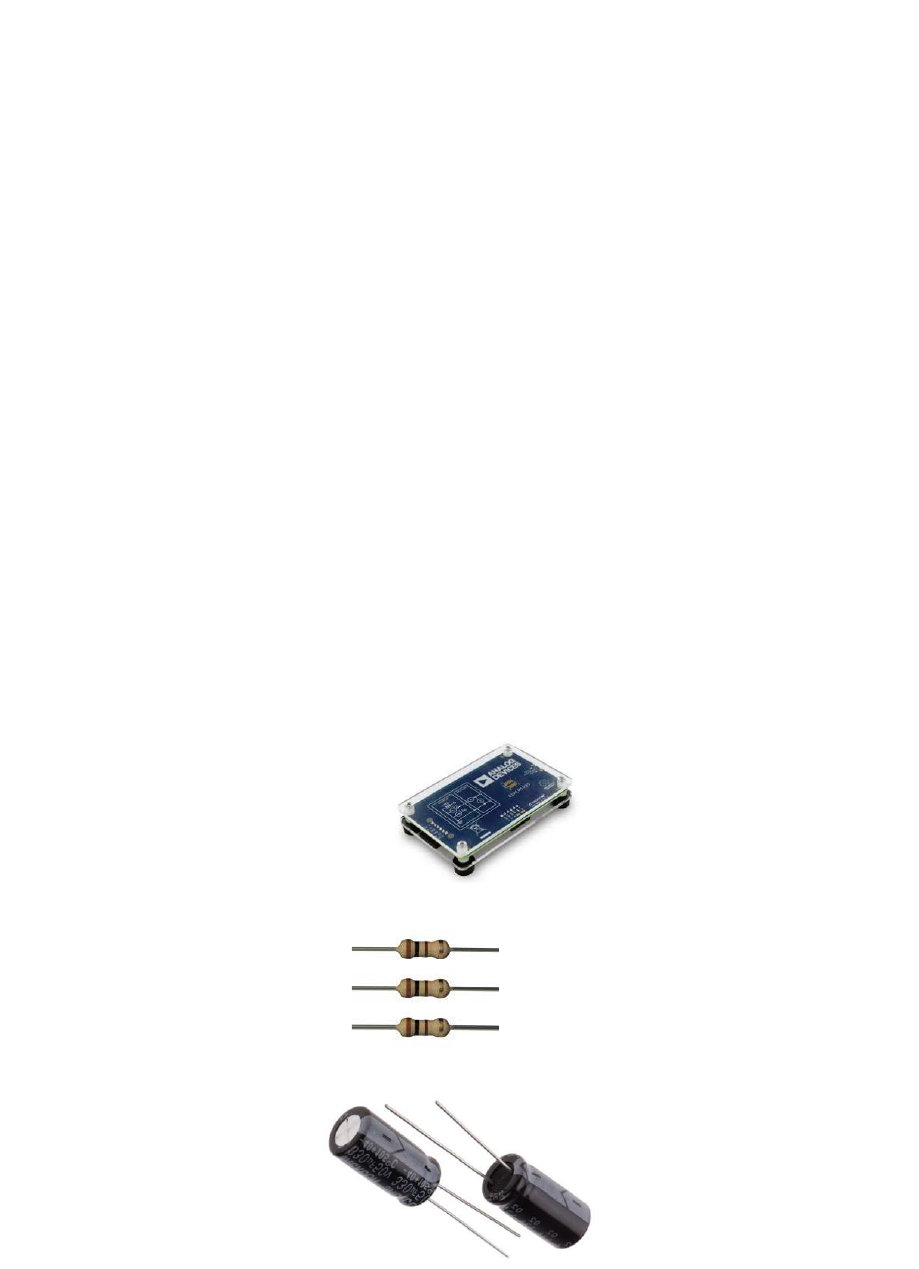
● ADALM1000 hardware module
● Resistors: 100 Ω, 1 kΩ
● Capacitors: 1 μF, 0.01 μF
● Inductors: 20 mH
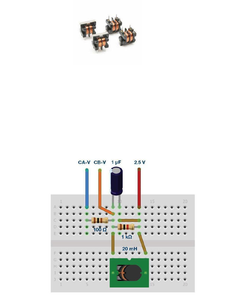
1.Set up the RLC circuit as shown in Figure 5 on your solderless breadboard, with the
component values RS = 100 Ω, R1 = 1 kΩ, C1 = 1 μF, and L1 = 20 mH.
Figure 5. Parallel resonance circuit with a series resistance connected to a source.
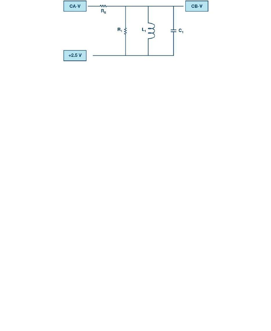
Figure 6. Parallel resonance circuit breadboard circuit.
2. Set the Channel AWG Min value to 0.5 and AWG Max value to 4.5 V to apply a 4 V p-p sine
wave centered on 2.5 V as the input voltage to the circuit. From the AWG A Mode drop-down
menu, select SVMI mode. From the AWG A Shape drop-down menu, select Sine. From the
AWG B Mode drop-down menu, select Hi-Z mode.
3. From the ALICE Curves drop-down menu, select CA-V and CB-V for display. From the
Trigger drop-down menu, select CA-V and Auto Level. Set the Hold Off to 2 ms. Adjust the
time base until you have approximately two cycles of the sine wave on the display grid. From the
Meas CA drop-down menu, select P-P under CA-V and do the same for CB. Also from the Meas
CA menu, select A-B Phase.
4. Vary the frequency of the sine wave on the AWG A menu from 500 Hz to 2.5 kHz in 100 Hz
steps. For each frequency, write down the p-p voltage for Channel A and Channel B and the A-B
phase. Note the frequency where the voltage is maximum at the output of the circuit for Channel
B. This will be near the resonant frequency of the circuit. Note that the phase should be nearly
0° at this frequency. Adjust the frequency in 10 Hz increments around where you see a
maximum for CB p-p voltage until the A-B phase is exactly zero.
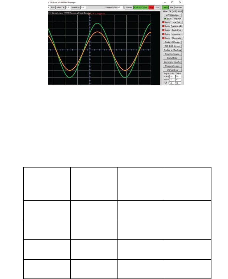
Figure 7. Input and output waveforms near resonant frequency.
5. Repeat the experiment using for the series resonant circuit in Figure 4, and use L1 = 20 mH
and C1 = 0.01 μF, and R1 = 1 kΩ. The voltage on the resistor is proportional to the series RLC
circuit current
Measurement
Voltage (v)
Resistance (R)
(Ohms=V/A)
Inductance (L)
(Henry's H = V)
1
2
3
4

V. References
1. Mercer, Doug, et al. “ADALM1000 SMU Training Topic 7: Resonance in RLC Circuit.” ADALM1000 SMU
Training Topic 7: REsonance in RLC Circuit | Analog Devices, https://www.analog.com/en/analog-
dialogue/studentzone/studentzone-july-2018.html.
VI. Appendix
Suggested Reading:
Circuit Globe. (2019). What is RLC Series Circuit? - Phasor Diagram & Impedance Triangle - Circuit Globe.
[online] Available at: https://circuitglobe.com/what-is-rlc-series-circuit.html [Accessed 9 Dec. 2019].
