
1
Al-Mustaqbal University College http://www.mustaqbal-college.edu.iq/
Experiment No.4
R-L-C Series Circuit
1. Introduction
An R-L-C series circuit is an electrical circuit containing a resistor R, an inductor L, and a
capacitor C, connected in series. The name of the circuit is derived from the letters that are
used to denote the constituent components of this circuit, where the sequence of the
components may vary from RLC.
The circuit forms a harmonic oscillator for current and resonates like an LC circuit.
Introducing the resistor increases the decay of these oscillations, which is also known as
damping. The resistor also reduces the peak resonant frequency. Some resistance is
unavoidable even if a resistor is not specifically included as a component.
2. Objectives
The experiment aims to study the electrical characteristics of an RLC circuit in series. Also,
to study the relation between the input frequency f and the circuit impedance Z.
3. Components
▪ Function generator
▪ Oscilloscope
▪ Resistor
▪ Inductor
▪ Capacitor
▪ Connection wires
4. Theory:
RLC circuits have many applications as oscillator circuits. Radio receivers and television
sets use them for tuning to select a narrow frequency range from ambient radio waves. In
this role, the circuit is often referred to as a tuned circuit. An RLC circuit can be used as a
Electrical Circuit Laboratory
Lecturer: Dr. Basim Al-Qargholi
Email: basim.alqargholi@mustaqbal-college.edu.iq
2
Al-Mustaqbal University College http://www.mustaqbal-college.edu.iq/
band-pass filter, band-stop filter, low-pass filter or high-pass filter. The tuning application,
for instance, is an example of band-pass filtering. The RLC filter is described as a second-
order circuit, meaning that any voltage or current in the circuit can be described by a
second-order differential equation in circuit analysis.
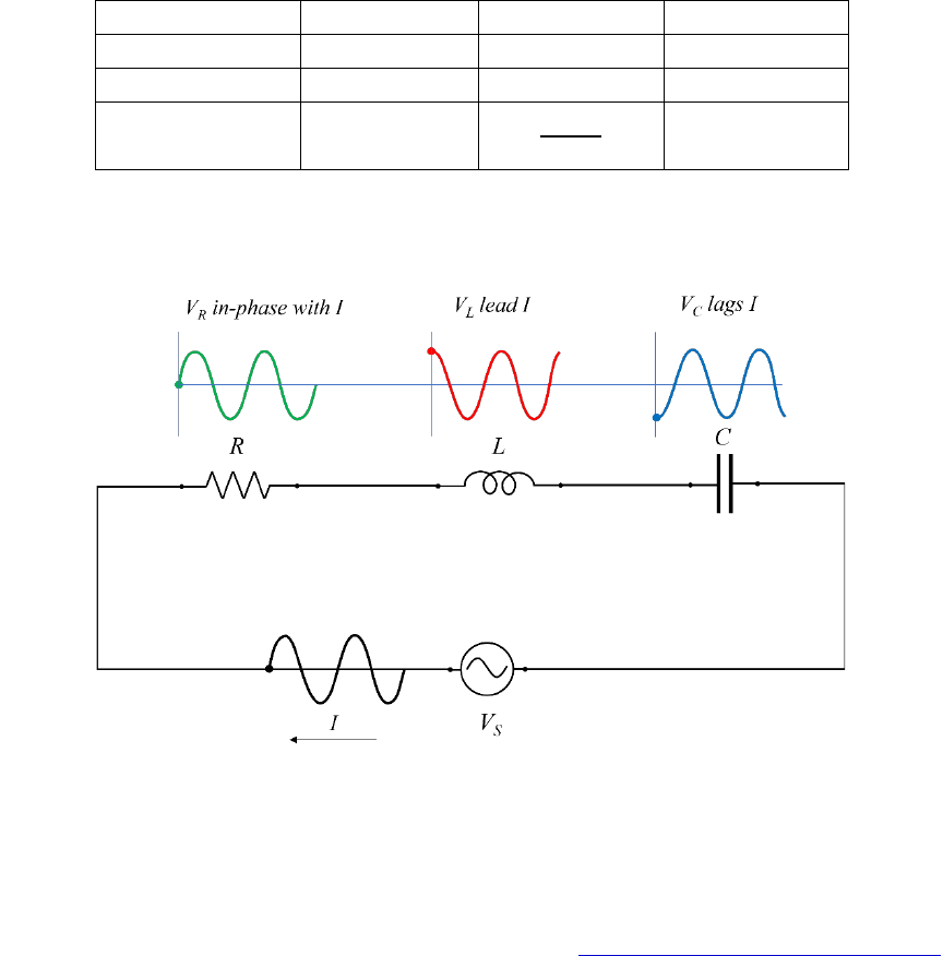
In a pure ohmic resistor the voltage waveforms are “in-phase” with the current. In a pure
inductance the voltage waveform “leads” the current by 90°. In a pure capacitance the
voltage waveform “lags” the current by 90°.
This phase difference, depends upon the reactive value of the components being used
and hopefully by now:
“We know that reactance, X is zero if the circuit element is resistive, positive if the
circuit element is inductive and negative if it is capacitive”
thus, giving their resulting impedances as:
Table 1: Shows the resistivity, reactence, and Theta of each element in the circuit.
Circuit element
Resistance, R
Reactance, X
Theta
Resistor
R
0
0
Inductor
0
+ 90°
Capacitor
0
- 90°
Instead of analysing each element individually, we can combine the three together elements
into a series RLC circuit.
Figure 1: illustrate the equivelant circuit or RLC in series and the voltages across each
element.
3
Al-Mustaqbal University College http://www.mustaqbal-college.edu.iq/
The analysis of a series RLC circuit is the same as that for the series RL and RC circuits we
looked at previously, except this time we need to consider the magnitudes of both X
L
and
X
C
to find the overall circuit reactance. Series RLC circuits are classed as second-order
circuits because they contain two energy storage elements, an inductance L and a
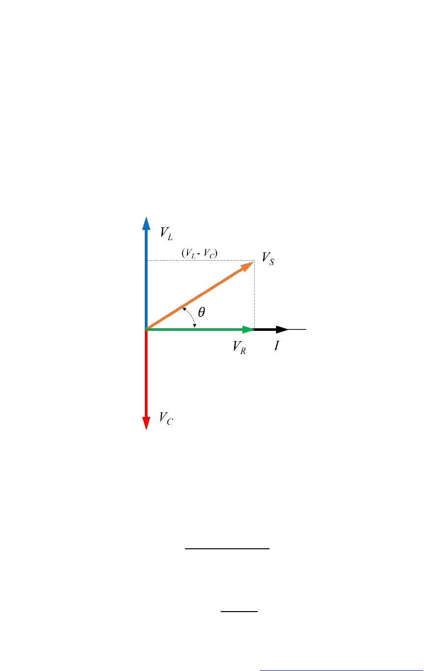
capacitance C. Consider the RLC circuit below. The phasor diagram for a series RLC circuit
is produced by combining the three individual phasors above and adding these voltages
vectorially. Since the current flowing through the circuit is common to all three circuit
elements, we can use this as the reference vector with the three voltage vectors drawn
relative to this at their corresponding angles.
The resulting vector V
S
is obtained by adding together two of the vectors, V
L
and V
C
and
then adding this sum to the remaining vector V
R
. The resulting angle obtained between V
S
and I will be the circuits phase angle as shown below.
We can see from the phasor diagram in Fig. 2 above that the voltage vectors produce a
rectangular triangle, comprising of hypotenuse V
S
, horizontal axis V
R
and vertical axis V
L
– V
C
. We notice that this forms our old favourite the Voltage Triangle and we can therefore
use Pythagoras’s theorem on this voltage triangle to mathematically obtain the value of V
S
as shown. The voltage triangle for a series RLC Circuit:
(1)
From Fig. 3, to calculate the phase diffrence of the RLC circuit:
(2)
Figure 2: Phasor Diagram for a Series RLC Circuit

4
Al-Mustaqbal University College http://www.mustaqbal-college.edu.iq/
Or
(3)
5. Experiment procedure
1- Build, connect the circuit shown in Fig. 1 using a 1kΩ resistor, a 100 mH inductor and
0.1µF capacitor.
2- Set the input voltage at 5V and frequency at 500 Hz.
3- Using the Oscilloscope, read the voltage across the 1kΩ resistor 100 mH inductor and
0.1µF capacitor.
4- Change the input frequency from 500 to 1 kHz, 1.5 kHz 2 kHz 2.5 kHz and 3 kHz.
5- Repeat step 3, measuring the voltage across the 1kΩ resistor 100 mH inductor and
0.1µF capacitor.
6- Based on the experimental measurement, Calculate the phase shift difference ()
theoretically using equation 2.
7- Write down all the measured and calculated values.
6. Discussion
1. What are the applications of the RLC circuit?
2. Why the phase shift () changed from negative to positive when we changed the
frequencies?
3. Based on the phase diagram in Fig. 3, if we remove the resistor, what will be at the
frequency 1.5 KHz
