Application Description
Application Description: Breakthrough in Test Procedures for Islanding Detection Page 1 of 9
Breakthrough in Test Procedures for Islanding Detection
New methods for Anti-Islanding Tests for Grid-tied Power Generator Equipment
according to IEEE 1547 or DIN V VDE V 0126-1-1 or VDE-AR-N 4105 by Means of
Simulated Impedance with REGATRON TC.ACS
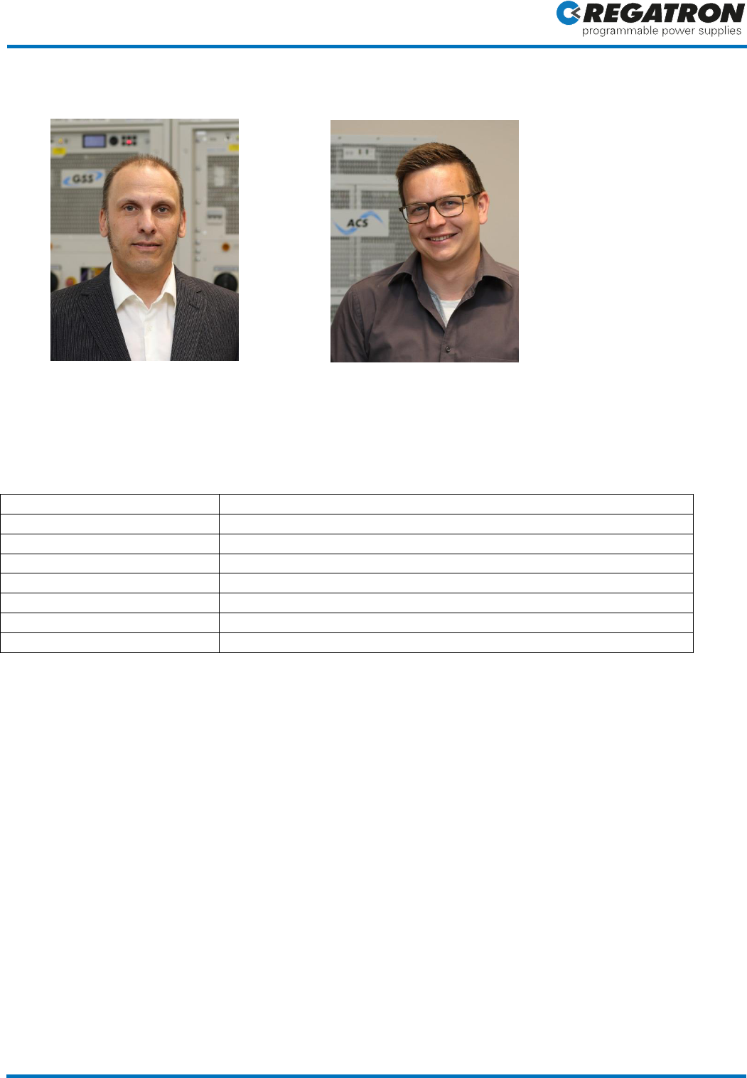
Authors: Bruno Ammann, B.Sc., Senior Field Application Engineer, REGATRON AG
Gabriel Schlaepfer, B.Sc., Development Engineer Hardware, REGATRON AG
Keywords: IEEE 1547, VDE V 0126-1-1:2013-08, VDE-AR-N 4105:2011-08, grid-tied power generating equipment, public
low-voltage grid, RLC tuned circuit, islanding condition, anti-islanding test, regenerative 4-quadrant grid simulator,
REGATRON TC.ACS, regenerative four quadrant operation, substitution of bulky and expensive RLC-components, RLCSim
mode, GRIDSim mode, ACSControl software, simulated complex impedance, Standard for Interconnecting Distributed
Resources with Electric Power Systems
Overview
The standards DIN V VDE V 0126-1-1 [1] or VDE-AR-N 4105 [2] or IEEE 1547 provide strict regulations for power
generating equipment feeding the public grid. The main aim is to harmonize all important technical specifications
and to prevent safety risks at “islanding” conditions.
Up to now test methods using passive tuned circuits require a considerable effort both in terms of expensive
components as also of work time. Power circuit simulation by REGATRON TC.ACS series allows for replacing lumped
component R-L-C-circuits simply by “Simulated Impedance”. Furthermore the same TC.ACS device can be used to
perform all necessary voltage and frequency tests based on the same test circuit, therefore the complete range of
test requirements according to standard DIN V VDE V 0126-1-1 [1] or IEEE 1547 is being met with a fraction of
expenditures both in time as in material.
Up-to-now Standard Test in Detail
With respect to frequency and voltage the standard DIN V VDE V 0126-1-1 [1] or VDE-AR-N 4105 [2] respectively
defines limits, the violation of which power equipment need to detect and then disconnect from the grid. The
device under test (DUT) has to disconnect from the grid autonomously within 0.1 second when voltages either fall
below 80% or exceed 115% of the nominal voltage (UN). Also frequencies (f) below 47.5 Hz and above 51.5 Hz must
result in disconnection within 0.1 second. Already today in many cases a grid simulator is used to confirm the
fulfillment of these requirements.
Moreover the DIN/VDE standard states that an islanding condition must be reliably detected and a disconnection
from the public low voltage system has to be executed within 5 seconds.
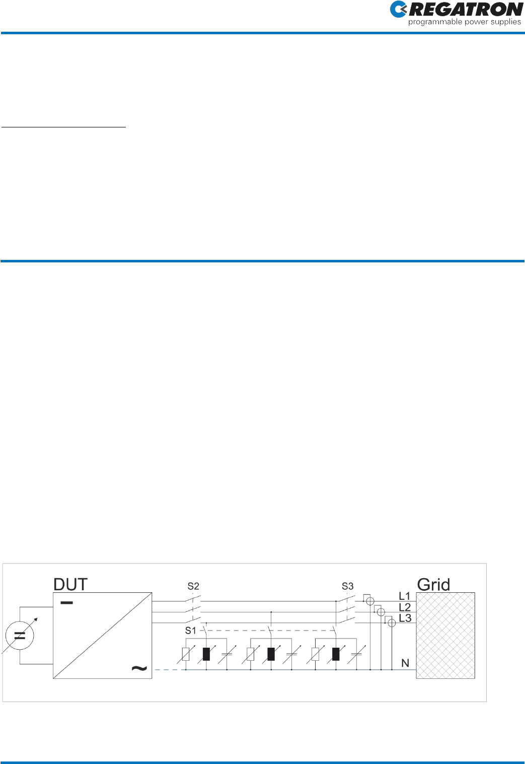
Figure 1: Test set-up for the detection of islanding operation according to VDE-AR-N 4105 [2]
Application Description
Application Description: Breakthrough in Test Procedures for Islanding Detection Page 2 of 9
In order to check the detection of islanding operation, R-L-C-circuits (see Figure 1) are connected in parallel to the
DUT/grid. Each R-L-C-circuit is dimensioned to absorb the complete active and reactive power of the respective
phase of the DUT. When the connection to the public system is being cut (S3), the DUT (a solar power inverter for
example) has to separate from the public grid within 5 seconds. This test has to be run with P = 25%, 50% and 100%
of the nominal power at the nominal frequency of ±0.1Hz and the nominal system voltage of ±3%. After each
successful test run one parameter (L or C) is altered by approx. 1% within a range of approx. ±5% and the test run is
repeated. Quite obviously, such a test is rather extensive with regards to material (different values of R, L and C
with the corresponding ratings of voltage and current) and time. Although automated solutions are available, these
are also material-consuming and expensive.
The quality factor Q of the R-L-C-circuit must be 2 at least. The active power being absorbed by the circuit must not
deviate from the active power fed by the power device for more than 3%. The following relationships apply:
The test is set up as follows:
- Setting the inductivity, such that Q >/= 2
- Setting the capacity, such that the reactive power (P
Q
) equals that of the DUT
- Setting the resistance, such that the active power equals that of the DUT
(in the case of lumped components this active power is transformed into heat!)
- Closing S1, S2, S3 and starting the DUT, the corresponding active/reactive power builds up
- Opening S3 ( islanding starts) and measuring the time until the DUT is turned off
State-of-the-art Solution Using Simulated R-L-C-Circuit
REGATRON offers unidirectional as well as bidirectional high-performance AC/DC power supplies in different ranges
of power and voltage. Beside these DC series, the TC.ACS Grid Simulator series represents a full 4-quadrant AC/AC
converter with excellent dynamics and power ranges of 0 to 30 kVA or 0 to 50 kVA respectively. By ingenious
paralleling techniques, a system power up to 1 MVA is achievable. TC.ACS grid simulators may be run either in Grid
Simulation mode, in R-L-C-Simulation mode or in a 3-phase Linear Amplifier mode specially designed for high speed
HIL applications. In the current control mode, TC.ACS is able to generate a current, which dynamically changes
according to the actual terminal voltage. By fast on-board computing techniques it is therefore possible to model
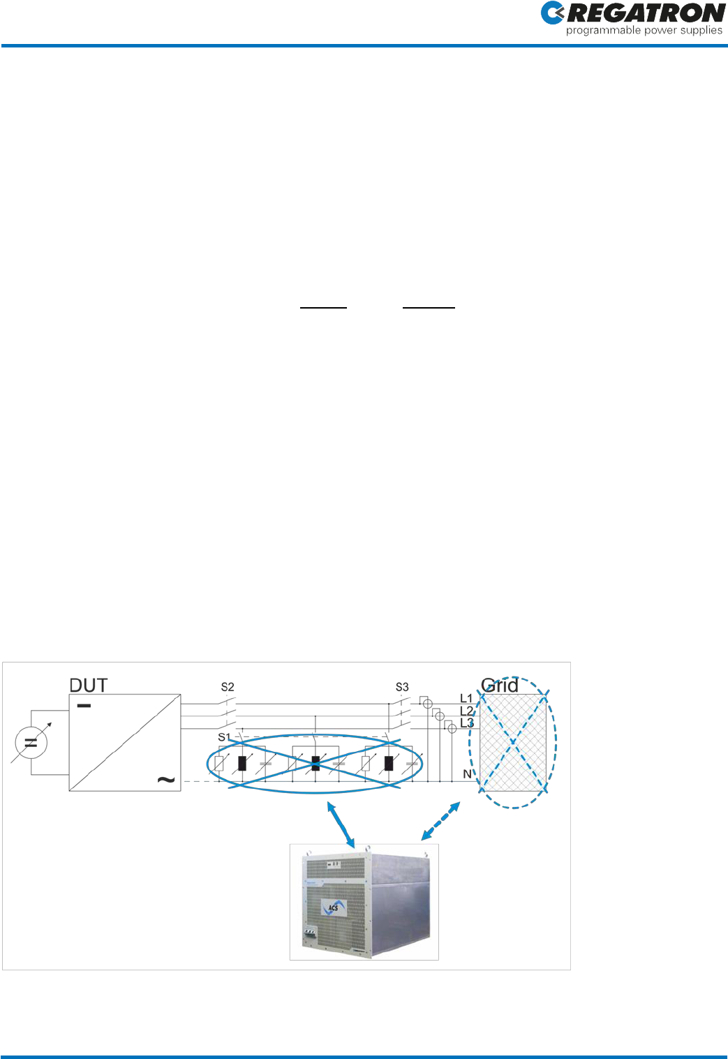
complex impedance and simulate even R-L-C-circuits in real-time (see Figures 2 and 3).
Figure 2: TC.ACS can be used to selectively simulate either the R-L-C-circuit or the public grid. This way both tests (detection of
islanding and monitoring of voltage/frequency) can be carried out using the same circuitry.
Application Description
Application Description: Breakthrough in Test Procedures for Islanding Detection Page 3 of 9
In R-L-C-simulation mode the TC.ACS simulates the R-L-C tuned circuits based on pre-calculated values, while in grid
simulation mode all voltage and frequency related tests easily may be performed. All relevant “component values”
can be adapted in full operation. A special API programming interface allows even for automatic stepwise variation
of parameters according to the standard VDE-AR-N 4105 [2]. It is obvious that the “Simulated Impedance Method”
simplifies the detection of islanding conditions strongly.
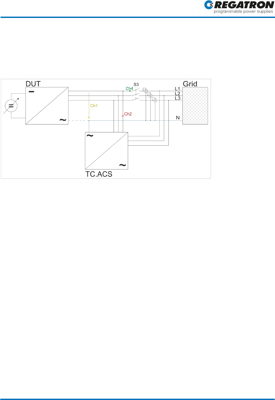
Figure 3: Test set-up using TC.ACS Impedance Simulation. For voltage and frequency related tests switch S3 stays
open and the grid is being simulated by TC.ACS operated in Grid Simulator mode. For the detection of islanding
switch S3 is closed, TC.ACS is operated in R-L-C-Simulation mode and the simulated R-L-C-circuits are adjusted in
full operation. S3 is reopened again to test the DUT’s behavior while in islanding condition.
The use of TC.ACS in Grid Simulation mode and R-L-C-Simulation mode offers the following benefits:
- No need for a respectable component warehouse of high power R/L/C-components
- No need for a time consuming handling and recalibration of bulky and partly heavy circuit components
- Drastically simplified test circuitry
- No need for any tuning of real components and reconnecting at each test step
- Simple “component value entry” by enclosed software ACSControl
- Drastically reduced time requirements
- Simplification of tuned circuit alignment and variations in full operation
Application Description
Application Description: Breakthrough in Test Procedures for Islanding Detection Page 4 of 9
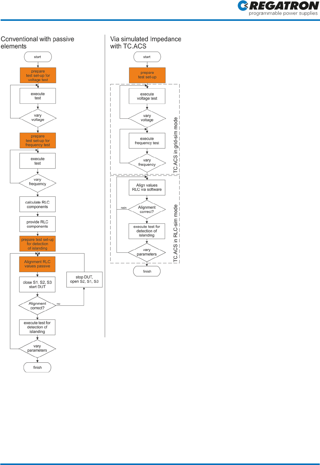
Figure 4: Flowcharts of the test sequences according to DIN/VDE regulations. On the left the conventional approach
is shown with passive elements and on the right the same test using the integrated solution. The steps highlighted
orange are those which require the most effort in work and material.
With the described test set-up it is possible to apply both single-phase as well as multi-phase blackouts to the DUT,
as required by the standard. In the single-phase case an R-L-C-system is simulated only on one phase, while on the
others an off-load operation is programmed.
Application Description
Application Description: Breakthrough in Test Procedures for Islanding Detection Page 5 of 9
Use Case: Testing a DC/AC Converter for the Detection of Islanding
In order to demonstrate the capability of the R-L-C-circuit simulation, a REGATRON TC.GSS is operated in
regenerative mode with a nominal power of 5 kW per phase (this is the DUT working as “Solar-inverter”). The
tuned circuits are simulated by TC.ACS with the values given in Table 1. As a driving DC power source (e.g. a “Solar
Array Simulation”) a further TC.GSS is being used.
Topology
Topology no. 12 (see figure 7)
R
12.6 Ω
C
900 μF
L
11.22 mH
R2
0.1 Ω
R3
0.4 Ω
Q
3
Cut-off frequency of voltage measurement
500 Hz
Table 1: Values for testing the detection of islanding condition
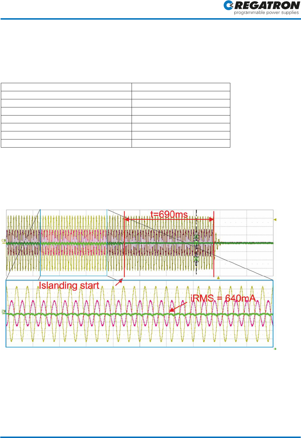
Cutting the grid by S3, the circuit shows a flawless perpetuation of the islanding operation by the TC.ACS in the RLC-
circuit-simulation mode. The DUT detects the islanding in turn and breaks off well within the defined period of time
(see Figure 5). The values of the R-L-C-circuit can be varied during operation in order to meet the required
tolerances.
Figure 5: Behavior of the R-L-C-Simulation during an islanding detection test. 690ms after the start of the islanding
the DUT shuts off.
Ch1 (yellow): Voltage L1-N at the input of the DUT
Ch2 (red): Current L1 at the output of the RLC-simulator TC.ACS
Ch4 (green): Current through S3 (current into the grid). In operating state the RMS-current into the grid is approx.
640mA and hence <3% of the nominal power.
Application Description
Application Description: Breakthrough in Test Procedures for Islanding Detection Page 6 of 9
Simple Use of the Enclosed Software
Both RLCSim and GridSim modes are operated by the software ACSControl, which is included in the scope of
delivery. In the GridSim mode a large variety of voltage patterns can be generated by the resident function
generator.
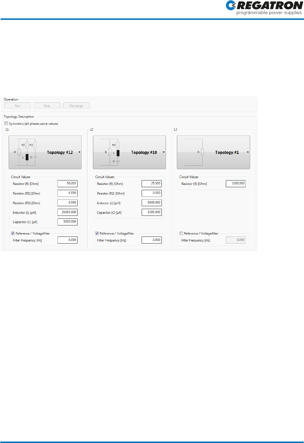
In RLCSim mode the parameter values are set by a user interface (see Figure 6). Subsequently, a circuit analysis is
performed creating a set of differential equations running in real-time onboard of TC.ACS. By this, phase currents
are dynamically computed as a function of the relative phase voltage.
Figure 6: Graphical interface of ACSControl software: The R-L-C-topology can be set per phase.
An adjustable low pass filter restricts the bandwidth of the voltage measurement, this helps to suppress unwanted
resonances within the simulation chain. At the same time voltage pulses are attenuated, preventing undesirably
high currents. Moreover, an application programming interface (API) provides the possibility to access the
individual parameters. Thus for instance the simulated load can variably be set via step functions, an important
feature when configuring automated test sequences.
Additional Areas of Application for the RLC-Simulation
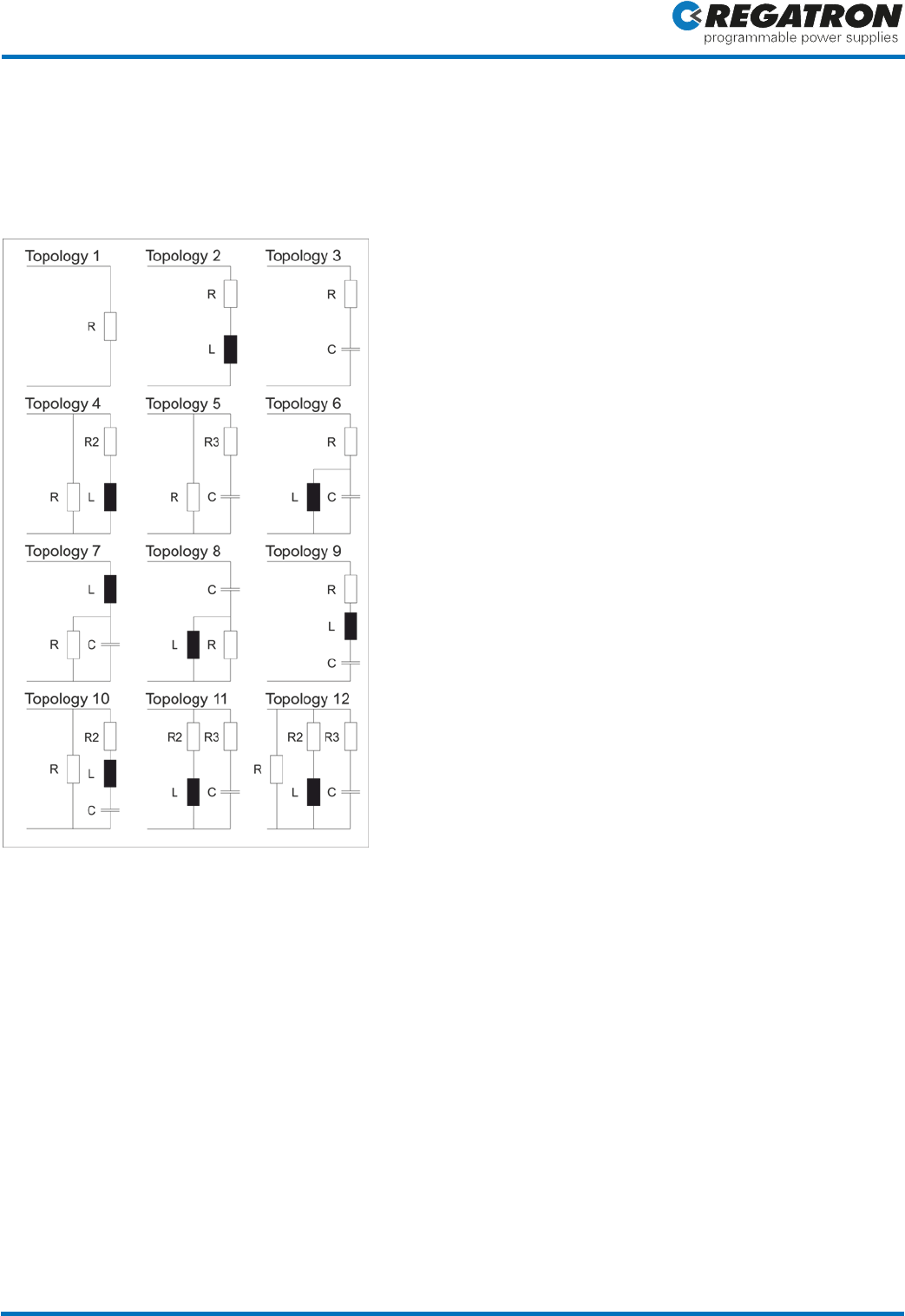
In addition to the described parallel resonant circuit above, currently further topologies are available for the
simulation of complex impedance, see figure 7 below.
The RLC simulation allows for definition of a wide variety of complex AC loads ranging from purely inductive to
purely capacitive in a high kVA area. Also cos- steps are possible in order to test phase shifters. Such tests are
feasible not only in the 3-phase-grid, but also for each individual phase.
One-phase to three-phase loads can easily be simulated observing the TC.ACS device specifications. AC load
simulation is very helpful for R+D work, AC network/grid definition and device testing as well as for educational
purposes. Moreover, the API allows for dynamic parameter variation, opening up the way to programmable load
variation, an indispensable topic for network analysis and dynamic AC device testing.
Application Description
Application Description: Breakthrough in Test Procedures for Islanding Detection Page 7 of 9
Testing devices with switch-mode output together with TC.ACS RLC-Simulation needs sometimes a special care.
Due to the complex impedance of TC.ACS output structure, unwanted AC noise may cause interference. In such
cases additional filtering (i.e. notch filters) will suppress the unwanted modulation frequency. By this technique,
even switch mode equipment can be tested easily in a RLC-Simulation environment.
Figure 7: Overview of the RLC-topologies currently available. These can be simulated according to the system limits
of the TC.ACS.
Application Description
Application Description: Breakthrough in Test Procedures for Islanding Detection Page 8 of 9
Constraints of the Simulation
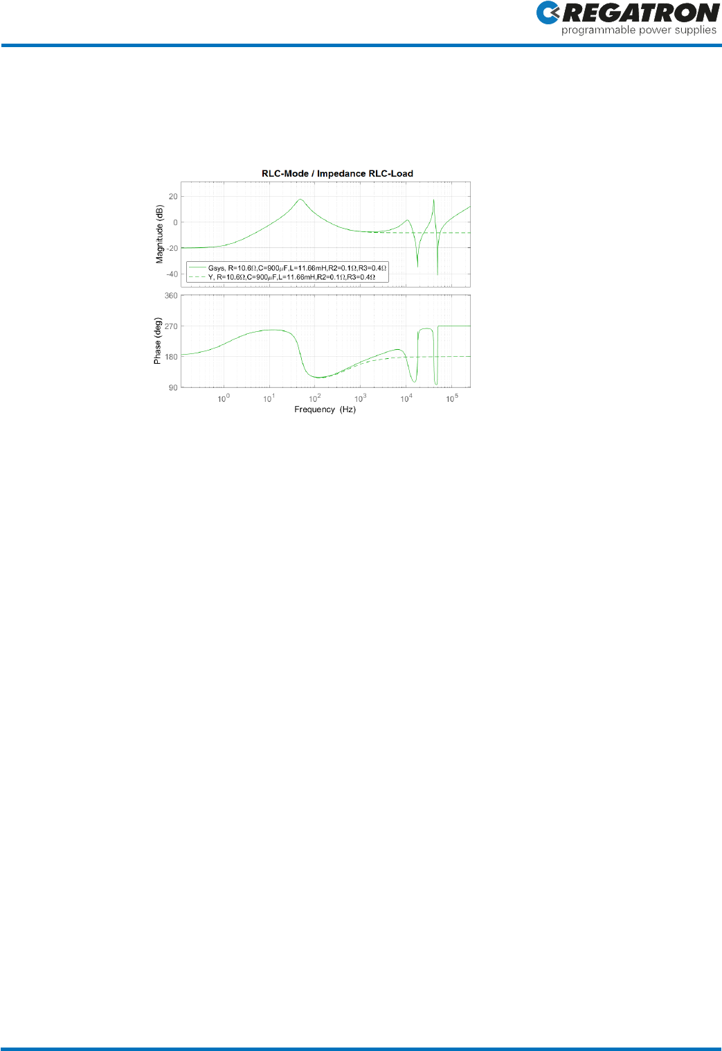
Figure 8: Comparison of the simulated (continuous) and the real (dotted) impedance according to the topology 12
of the RLC-operation with the following values: R=10.6Ω, C=900μF, L=11.66mH, R2=0.1Ω, R3=0.4Ω.
The influence of the TC.ACS output filter is clearly visible in the frequency range > 1kHz.
In the frequency range below 1 kHz there are only small local deviances between the real and the computed
impedance due to measuring tolerances and nonlinearities in the control circuit. However, these are comparable to
tolerances of real components. By adjustment of the component values it is possible at any time to tune the values
such that the test requirements are met.
Sources
[1]
DKE Deutsche Kommission Elektrotechnik Elektronik Informationstechnik im DIN und VDE. DIN V VDE V 0126-1-1:2013-08 Selbsttätige
Schaltstelle zwischen einer netzparallelen und Eigenerzeugungsanlage und dem öffentlichen Netzspannungsnetz.
[2]
DKE Deutsche Kommission Elektrotechnik Elektronik Informationstechnik im DIN und VDE. VDE-VR-N 4105:2011-08 Erzeugungsanlagen
am Niederspannungsnetz - Technische Mindestanforderungen für Anschluss und Parallelbetrieb von Erzeugungsanlagen am
Niederspannungsnetz.
Application Description
Application Description: Breakthrough in Test Procedures for Islanding Detection Page 9 of 9
Authors
Manufacturer
REGATRON AG, Feldmuehlestrasse 50, CH-9400 Rorschach
Contact Person
Bruno Ammann, B.Sc., Senior Field Application Engineer
Phone
+41 71 846 67 01
E-Mail
tc.engineering@regatron.ch
Additional Information
www.regatron.com/applications/
Author and Copyright
REGATRON AG
Published on
July 6
th
, 2018
Document ID
18070602
This information is subject to change without notice.
*****
Bruno Ammann, B.Sc.
Senior Field Application Engineer
REGATRON AG
Gabriel Schläpfer, B.Sc.
Development Engineer Hardware
REGATRON AG
