User manual
COM OPEN PROTOCOL MDCv2/MDTC series
EN
60428-05/23
www.dogassembly.com

Manual COM OPEN PROTOCOL MDCv2/MDTC series 3 DOC.60428-05/23
INDEX
1. Controller firmware version ............................................................ Erreur ! Signet non défini.
2. COMMUNICATION TYPE ........................................................................................................ 5
2.1 Serial Protocol ................................................................................................................. 5
2.2 Ethernet Protocol ............................................................................................................. 5
3. MESSAGE STRUCTURE ........................................................................................................ 6
3.1 Header ............................................................................................................................ 6
3.2 Serial message example ................................................................................................. 7
3.3 Ethernet message example ............................................................................................. 7
4. COMMUNICATION FLOW ....................................................................................................... 8
4.1 Serial Connection flow ..................................................................................................... 8
4.2 Ethernet Connection flow ................................................................................................. 8
4.3 Communication flow chart example ................................................................................. 9
5. Communication messages ..................................................................................................... 10
5.1 MID control type ............................................................................................................ 10
5.1.1 MID 0001 Communication start ................................................................................ 11
5.1.2 MID 0002 Communication start acknowledge .......................................................... 11
5.1.3 MID 0003 Communication stop ................................................................................ 12
5.1.4 MID 0004 Command error ....................................................................................... 12
5.1.5 MID 0005 Command accepted ................................................................................ 14
5.1.6 MID 0010 Parameter set ID (Preset number) upload request................................... 14
5.1.7 MID 0011 Parameter set ID (Preset number) upload reply ....................................... 15
5.1.8 MID 0012 Parameter set (Preset) data upload request ............................................ 15
5.1.9 MID 0013 Parameter set (Preset) data upload reply ................................................ 16
5.1.10 MID 0018 Select Parameter set (Preset).................................................................. 17
5.1.11 MID 0040 Tool data upload request ......................................................................... 18
5.1.12 MID 0041 Tool data upload reply ............................................................................. 18
5.1.13 MID 0042 Disable tool.............................................................................................. 21
5.1.14 MID 0043 Enable tool .............................................................................................. 21
5.1.15 M
ID 0060 Last tightening result data subscribe........................................................ 22
5.1.16 MID 0061 Last tightening result data ........................................................................ 23
5.1.17 MID 0062 Last tightening result data acknowledge .................................................. 28
5.1.18 MID 0063 Last tightening result data unsubscribe .................................................... 29
5.1.19 MID 0070 Alarm subscribe ....................................................................................... 29
5.1.20 MID 0071 Alarm ....................................................................................................... 30
5.1.21 MID 0072 Alarm acknowledge ................................................................................. 31

Manual COM OPEN PROTOCOL MDCv2/MDTC series 4 DOC.60428-05/23
5.1.22 MID 0073 Alarm unsubscribe ................................................................................... 31
5.1.23 MID 1000 Read parameter value ............................................................................. 32
5.1.24 MID 1001 Read parameter value acknowledge ....................................................... 32
5.1.25 MID 1002 Write parameter value ............................................................................. 33
5.1.26 MID 1003 Write parameter value acknowledge ........................................................ 33
5.1.27 MID 9999 Keep alive message ................................................................................ 34
5.2 Event message .............................................................................................................. 34
5.2.1 Event subscribe – unsubscribe messages ............................................................... 34
5.2.2 Event message acknowledge .................................................................................. 34
Manual COM OPEN PROTOCOL MDCv2/MDTC series 5 DOC.60428-05/23
1. CONTROLLER FIRMWARE VERSION
Newer update MID40/41 applied since following firmware versions :
MDCv2 26 & 32 : MDC_v2.31.7_20230321.bin and newer
MDTC38 : MDTC_Normal_v1.31.5_230321.bin and newer
MDTC38 + : MDTC_Plus_v3.31.5_230321.bin and newer
2. COMMUNICATION TYPE
2.1 Serial Protocol
• Serial ASCII protocol
• Request message from Integrator to controller :
Add BEL(0x07), HT(0x09), BEL(0x07), HT(0x09)
as prefix.
• Respose message from controller to Integrator :
Add STX (0x02) as prefix, ETX(0x03) as sufix.
2.2 Ethernet Protocol
• TCP/IP Protocol
• After TCP/IP connection confirmation,
Message can be delivered.
• There is no Prefix and sufix as like BEL, HT
in serial communication.

Manual COM OPEN PROTOCOL MDCv2/MDTC series 6 DOC.60428-05/23
3. MESSAGE STRUCTURE
Header
Data Field Message End
Length
MID
Revision
No
ack
flag
Station
ID
Spindle
ID
Spare
---
NUL
(Hex 0x00)
20Byte
Max 1004Byte
3.1 Header
Part Bytes
Comment
Length
4
Total length of message except prefix and sufix (BEL, HT, STX, ETX)
Range: 0000 ~ 9999
MID
4
Command message (Ex: Parameter save, Disable tool)
Range: 0001 ~ 9999
Revision
3
Message version
According to the MID, Data type and lenght is different.
No ack
flag
1
Require Ack message as a response ?
0: YES 1: NO
Station
ID
2
No use. Replace with 0x20(space)
Spindle
ID
2
Spare
4
Spare. No use. Replace with 0x20(space)
Note.
- The empty space Byte in Length and MID should be replaced with 0x30(0)
Manual COM OPEN PROTOCOL MDCv2/MDTC series 7 DOC.60428-05/23
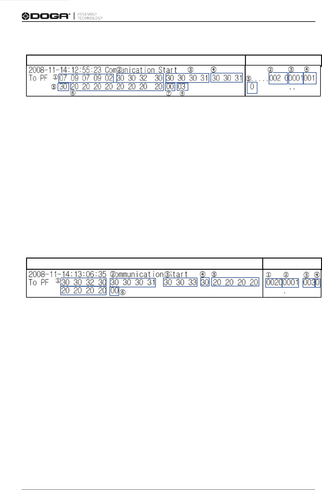
3.2 Serial message example
1. BEL, HT, BEL, HT, STX : Prefix of the message from Integrator to controller.
2. 0020(Decimal): Total message length is 20byte.
3. 0001(Decimal): MID (command) 1 is for communication start.
4. 001(Decimal): The current message version is 1
st
.
5. 0(Decimal): “0” requires ACK response.
6. 20 20…(hex): No use with Space(0x20).
7. 00(hex): NULL.
8. 03(hex): ETX. The end of Message.
3.3 Ethernet message example
1. 0020: Total message length is 20byte.
2. 0001: MID (command) 1 is for communication start.
3. 003: Revision. The current message version is 3
th
.
4. 0: No ack flag. “0” requires ACK response.
5. 20 20…(hex): No use with Space(0x20).
6. 00(hex): NULL
A
)
SCII (Hex
D
ecimal
A
SCII (Hex)
D
ecimal
Manual COM OPEN PROTOCOL MDCv2/MDTC series 8 DOC.60428-05/23
4. COMMUNICATION FLOW
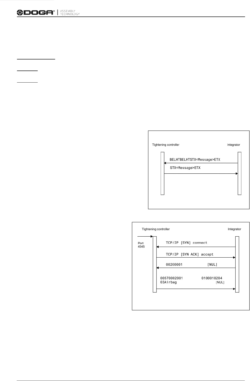
4.1 Serial Connection flow
1. Integrator send MID 0001 message to
controller for communication start.
2. Controller response with MID 0002 ACK
message which means communication
start.
4.2 Ethernet Connection flow
1. Integrator request TCP connection to
Controller.
2. Controller response TCP accept
message.
3. Integrator send MID 0001 message to
controller for communication start.
4. Controller response with MID 0002 ACK
message which means communication
start.
Manual COM OPEN PROTOCOL MDCv2/MDTC series 9 DOC.60428-05/23
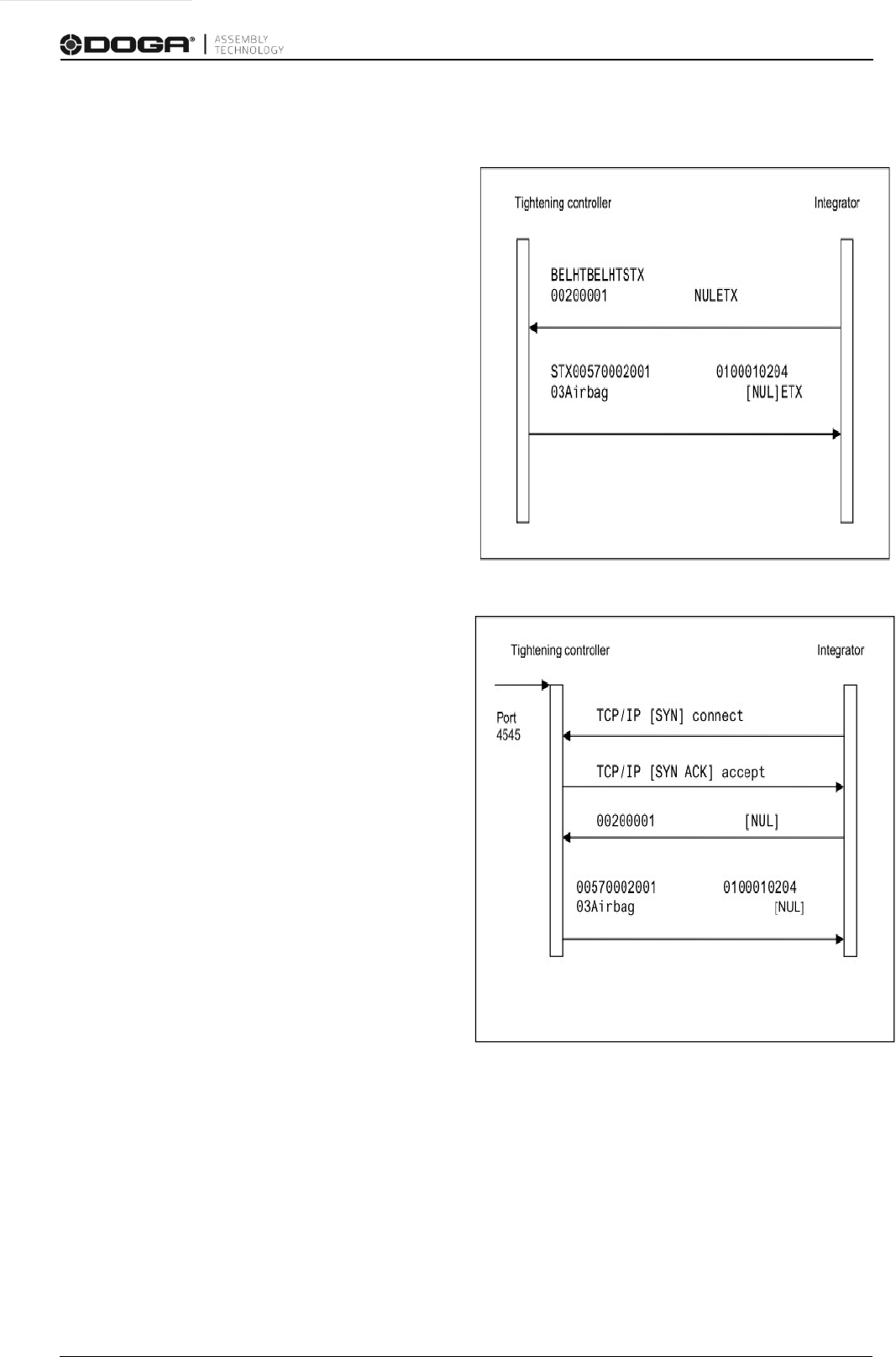
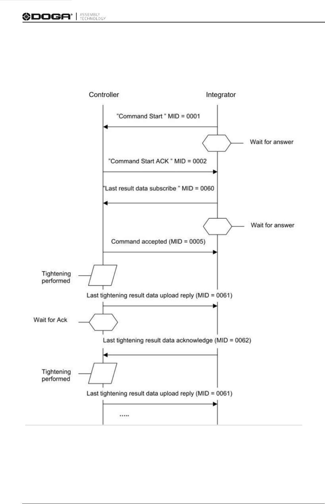
4.3 Communication flow chart example
Ex) Establish a connection and set result subscription

Manual COM OPEN PROTOCOL MDCv2/MDTC series 10 DOC.60428-05/23
5. Communication messages
5.1 MID control type
ID
Description
Sent by
0001
Communication start
Integrator
0002
Communication start acknowledge
Controller
0003
Communication stop
Integrator
0004
Command error
Controller
0005
Command accepted
Controller
0010
Parameter set ID(Preset number) upload request
Integrator
0011
Parameter set ID(Preset number) upload reply
Controller
0012
Parameter set(Preset) data upload request
Integrator
0013
Parameter set(Preset) data upload reply
Controller
0018
Select Parameter set(Preset)
Integrator
0040
Tool data upload request
Integrator
0041
Tool data upload reply
Controller
0042
Disable Tool
Integrator
0043
Enable Tool
Integrator
0060
Last tightening result data subscribe
Integrator
0061
Last tightening result data
Controller
0062
Last tightening result data acknowledge
Integrator
0063 Last tightening result data unsubscribe Integrator
0070
Alarm subscribe
Integrator
0071
Alarm
Controller
0072
Alarm acknowledge
Integrator
0073
Alarm unsubscribe
Integrator
1000
Read Parameter value
Integrator
1001
Read Parameter value acknowledge
Controller
1002
Write parameter value
Integrator
1003
Write parameter value acknowledge
Controller
9999
Keep alive open protocol communication
Integrator

Manual COM OPEN PROTOCOL MDCv2/MDTC series 11 DOC.60428-05/23
5.1.1 MID 0001 Communication start
This message enables the communication. The controller does not respond to any other
command before this
� Message sent by: Integrator
� Answers: MID 0002 Communication start acknowledge or
MID 0004 Command error, Client already connected or MID revision unsupported
Example: Communication start with call for
MID 0002 Communication start acknowledge
revision 3.
00200001003
NUL
Message part
Parameter
Byte
Value
Header
Length
1-4
0020
MID
5-8
0001
Revision of MID 0002
9-11
Range: 001
No Ack flag
12
N/A
Station ID
13-14
N/A
Spindle ID
15-16
N/A
Spare
17-20
N/A
Data field
N/A
0
N/A
Message end
21
NUL
5.1.2 MID 0002 Communication start acknowledge
When accepting the communication start the controller sends as reply, a
Communication start acknowledge. This message contains some basic information
about the controller, such as cell ID, channel ID, and name.
� Message sent by: Controller
� Answer: None
Example, revision 1: The connected controller belongs to cell 1, the channel ID is
1 and the name is Airbag1
00570002
010001020103Airbag1
NUL
Message part
Parameter
Byte
Value
Header
Length
1-4
Rev 1: 0057
MID
5-8
0002
Revision
9-11
Range: 001
No Ack flag
12
N/A
Station ID
13-14
N/A
Spindle ID
15-16
N/A
Spare
17-20
N/A
Data field
Controller information
21-length
See Table 1
Message end
Rev 1: 58
NUL

Manual COM OPEN PROTOCOL MDCv2/MDTC series 12 DOC.60428-05/23
Table 1 MID 0002 Revision 1
Parameter
Byte
Value
Cell ID
21-22
01
23-26
The cell ID don’t use. (Fill with 0x30)
Channel ID
27-28
02
29-30
The channel ID don’t use. (Fill with 0x30)
Controller Name
31-32
03
33-57
The controller name is 25 bytes long and specified by 25 ASCII
characters
5.1.3 MID 0003 Communication stop
This message disables the communication. The controller will stop to respond to any commands
except for
MID 0001 Communication start after receiving this command.
� Message sent by: Controller:
� Answer: MID 0005 Command accepted
Message part
Parameter
Byte
Value
Header
Length
1-4
0020
MID
5-8
0003
Revision
9-11
00-01
No Ack flag
12
N/A
Station ID
13-14
N/A
Spindle ID
15-16
N/A
Spare
17-20
N/A
Data field
N/A
N/A
Message end
21
NUL
5.1.4 MID 0004 Command error
This message is used by the controller when a request for any reason has not been
performed. The data field contains the message ID of the message request that failed
as well as an error code.
� Message sent by: Controller:
� Answer: None
Example: The request
MID 0018 Select parameter set failed, the parameter set number was not
present in the controller.
00260004
001802NUL

Manual COM OPEN PROTOCOL MDCv2/MDTC series 13 DOC.60428-05/23
Message part
Parameter
Byte
Value
Header
Length
1-4
0026
MID
5-8
0004
Revision
9-11
Range: 000-001
No Ack flag
12
N/A
Station ID
13-14
N/A
Spindle ID
15-16
N/A
Spare
17-20
N/A
Data field
MID and error code
21-26
see Table 2.
Message end
27
NUL
Table 2 MID 0004 Data field (Error code description)
ID
Description
00
No Error
01
Invalid data
02
Parameter set : ID not present
03
Parameter set : can not be set.
04
Parameter set : not running
09
Last tightening result subscription already exists
10
Last tightening result subscription does not exist
11
Alarm subscription already exists
12
Alarm subscription does not exist
13
Parameter set selection subscription already exists
14
Parameter set selection subscription does not exist
16
Connection rejected protocol busy
58
No alarm present
79
Command failed
96
Client already connected
97
MID revision unsupported
98
Controller internal request timeout
99
Unknown MID

Manual COM OPEN PROTOCOL MDCv2/MDTC series 14 DOC.60428-05/23
5.1.5 MID 0005 Command accepted
This message is used by the controller to confirm that the latest request sent by the
integrator was accepted. The data field contains the MID of the request accepted.
� Message sent by: Controller.
� Answer: None.
Example: The request
MID 0018 Select parameter set is accepted.
00240005
0018NUL
Message part
Parameter
Byte
Value
Header
Length
1-4
0024
MID
5-8
0005
Revision
9-11
Range: 000-001
No Ack flag
12
N/A
Station ID
13-14
N/A
Spindle ID
15-16
N/A
Spare
17-20
N/A
Data field
MID accepted
21-24
Four ASCII digits
Message end
25
NUL
5.1.6 MID 0010 Parameter set ID (Preset number) upload request
A request to get the valid parameter set IDs from the controller.
� Message sent by: Integrator
� Answer: MID 0011 Parameter set ID upload reply
Message part
Parameter
Byte
Value
Header
Length
1-4
0020
MID
5-8
0010
Revision, MID 0011
9-11
Range: 000-001
No Ack flag
12
N/A
Station ID
13-14
N/A
Spindle ID
15-16
N/A
Spare
17-20
N/A
Data field
N/A
N/A
Message end
21
NUL

Manual COM OPEN PROTOCOL MDCv2/MDTC series 15 DOC.60428-05/23
5.1.7 MID 0011 Parameter set ID (Preset number) upload reply
The transmission of all the valid parameter set IDs of the controller. The data field
contains the number of valid parameter sets currently present in the controller, and the
ID of each parameter set present.
� Message sent by: Controller
� Answer: None
Example: parameter set 1 and 2 are present in the controller.
00290011
002001002NUL
Message part
Parameter
Byte
Value
Header
Length 1-4
Length depends on the number of parameter sets. 23
+ number of parameter sets x3
MID
5-8
0011
Revision
9-11
Range: 000-001
No Ack flag
12
N/A
Station ID
13-14
N/A
Spindle ID
15-16
N/A
Spare
17-20
N/A
Data field, part 1
The number of
parameter sets in the
controller
21-23
Three ASCII digits. Range: 001-015
Data field, part 2
The ID of each
parameter set present
24 -
Three ASCII digits for each parameter set
Message end
Length +1
NUL
5.1.8 MID 0012 Parameter set (Preset) data upload request
Request to upload parameter set data from the controller.
� Message sent by: Integrator
� Answer: MID 0013 Parameter set data upload reply, or
MID 0004 Command error, Parameter set not present
Example: Request to upload parameter set data for parameter set 1.
00230012
001NUL
Message part
Parameter
Byte
Value
Header
Length
1-4
0023
MID
5-8
0012
Revision, MID 0013
9-11
Range: 001
No Ack flag
12
N/A
Station ID
13-14
N/A
Spindle ID
15-16
N/A
Spare
17-20
N/A
Data field
Parameter set ID
21-23
Three ASCII digits. Range: 001-015
Message end
24
NUL

Manual COM OPEN PROTOCOL MDCv2/MDTC series 16 DOC.60428-05/23
5.1.9 MID 0013 Parameter set (Preset) data upload reply
Upload of parameter set data reply. The following tables show the revisions available:
� Message sent by: Controller
� Answer: None
Example: Upload parameter set data for parameter set 1 called Airbag 1.
01040013 0100102Airbag1 031040305001200
0600150007001400080036009007201000480NUL
Message part
Parameter
Byte
Value
Header
Length
1-4
0104
MID
5-8
0013
Revision
9-11
Range: 001
No Ack flag
12
N/A
Station ID
13-14
N/A
Spindle ID
15-16
N/A
Spare
17-20
N/A
Data field
Parameter set data
21-104
See Table 3
Message end
105
NUL
Table 3 MID 0013 Revision 1
Parameter
Byte
Value
Parameter set ID
21-22
01
23-25
Three ASCII digits, range 001-015
Parameter set name
26-27
02
28-52
Parameter set name don’t use.
Rotation direction
53-54
03
55
1=CW, 2=CCW
Batch size
56-57
04
58-59
The batch size doesn’t use. (Fill with 0x30)
Torque min
60-61
05
62-67
The torque min limit is multiplied by 100 and sent as an integer
(2 decimals truncated). It is six bytes long and is specified by six
ASCII digits.
Torque max
68-69
06
70-75
The torque max limit is multiplied by 100 and sent as an integer
(2 decimals truncated. It is six bytes long and is specified by six
ASCII digits.
Torque final target
76-77
07

Manual COM OPEN PROTOCOL MDCv2/MDTC series 17 DOC.60428-05/23
Parameter
Byte
Value
Torque final target
78-83
The torque final target is multiplied by 100 and sent as an integer
(2 decimals truncated). It is six bytes long and is specified by six
ASCII digits.
Angle min
84-85
08
86-90
The angle min value is five bytes long and is specified by five ASCII
digits. Range: 00000-99999.
Angle max
91-92
09
93-97
The angle max value is five bytes long and is specified by five
ASCII digits. Range: 00000-99999.
Final Angle Target
98-99
10
100-104
The target angle is specified in degrees. 5 ASCII digits. Range:
00000-99999.
5.1.10 MID 0018 Select Parameter set (Preset)
Select a parameter set.
� Message sent by: Integrator
� Answer: MID 0005 Command accepted or
MID 0004 Command error, Parameter set can not be set
The Pset will then be automatically selected when the operator chooses the correct socket
from the selector.
Subscription of the currently selected Pset via MID 0014 will show when the operator has
selected the correct Pset.
Message part
Parameter
Byte
Value
Header
Length
1-4
0023
MID
5-8
0018
Revision
9-11
Range : 000-001
No Ack flag
12
N/A
Station ID
13-14
N/A
Spindle ID
15-16
N/A
Spare
17-20
N/A
Data field
Parameter set ID
21-23
Three ASCII digits, range 001-015
Message end
24
NUL

Manual COM OPEN PROTOCOL MDCv2/MDTC series 18 DOC.60428-05/23
5.1.11 MID 0040 Tool data upload request
A request for some of the data stored in the tool. The result of this command is the transmission of the tool
data.
Message sent by: Integrator
Answer:
MID 0041 Tool data upload reply
Message part
Parameter
Byte
Value
Header
Length
1-4
0020
MID
5-8
0040
Revision, MID 0041
9-11
Range: 000-004
No Ack flag
12
N/A
Station ID
13-14
N/A
Spindle ID
15-16
N/A
Spare
17-20
N/A
Data field
N/A
N/A
Message end
21
NUL
5.1.12 MID 0041 Tool data upload reply
Upload of tool data from the controller.
Message sent by: Controller
Answer: None
Example: Tool data
00810041 01C341212 02548796 032001-05-07:13:24:5404670919 NUL
Message part
Parameter
Byte
Value
Header
Length
1-4
Revision 1: 0081
Revision 2: 0156
MID
5-8
0041
Revision
9-11
Range: 000-004
No Ack flag
12
N/A
Station ID
13-14
N/A
Spindle ID
15-16
N/A
Spare
17-20
N/A
Data field
Tool data
21-length
See Table 31,Table 32, Table 33
Message end
N/A
Rev 1: 82
Rev 2: 157
NUL

Manual COM OPEN PROTOCOL MDCv2/MDTC series 19 DOC.60428-05/23
Table 31 MID 0041 Tool data, revision 1
Parameter
Byte
Value
Tool serial number
21-22
01
23-36
14 ASCII characters
Tool number of tightening
37-38
02
39-48
10 ASCII digits. Max 4294967295 - N.A. on MD tools
Last calibration date
49-50
03
51-69
19 ASCII characters. YYYY-MM-DD:HH:MM:SS
N.A. on MD/MDT tools
Controller serial number =
Ford. RBU Serial = Normal
70-71
04
72-81
10 ASCII characters
N.A. on MD/MDT tools
Table 32 MID 0041 Tool data, additions for revision 2
Parameter
Byte
Value
Calibration value
82-83
05
84-89
The tool calibration value is multiplied by 100 and sent as an
integer (2 decimals truncated). Six ASCII digits.
Last service date
90-91
06
92-110
YYYY-MM-DD:HH:MM:SS - N.A. on MD/MDT tools
Tightenings since service
111-112
07
113-122
The number of tightenings since last service is specified by 10
ASCII digits. Max 4294967295. - N.A. on MD tools
Tool type
123-124
08
125-126
The tool type is specified by 2 ASCII digits:
00=No Tool, 01=S-tool, 02=DS-tool, 03=Ref. transducer,
04=STtool, 05=EP-tool, 06=ETX-tool, 07=SL-tool, 08=DL-tool,
09=IRC Offline, 10=STB-tool, 11=QST-tool, 12=STT-tool,
13=STwrench,
14 = ES-tool
30 = MD (Doga)
31= MDT (Doga)
Motor size
127-128
09
129-130
The motor size is specified by 2 ASCII digits,
range 00-99.
00 = no motor, 01-99 = motor size xx in Atlas Copco
nomenclature, or motor size = 10xx in Atlas Copco nomenclature
(certain numbers correspond to 2 different motor sizes, for
example 62 for both motor size 62 and motor size 1062)
Open end data
131-132
10
133-135
The open end data is specified by 3 ASCII digits.
The first digit represents the “use open end”: 1=true, 0=false.
The second digit indicates the tightening direction: 0=CW,
1=CCW.
The third digit indicates motor rotation: 0=normal, 1=inverted.
N.A. on MD/MDT tools
Controller software version
136-137
11
138-156
The software version is specified by 19 ASCII characters.

Manual COM OPEN PROTOCOL MDCv2/MDTC series 20 DOC.60428-05/23
Table 33 MID 0041 Tool data, additions for revision 3
Parameter
Byte
Value
Tool max torque
157-158
12
159-164
The tool max toque value is multiplied by 100 and sent as an
integer (2 decimals truncated). Six ASCII digits.
Gear ratio
165-166
13
167-172
The gear ratio value is multiplied by 100 and sent as an integer (2
decimals truncated). Six ASCII digits.
Tool full speed
173-174
14
175-180
The tool full speed value is multiplied by 100 and sent as an
integer (2 decimals truncated). Six ASCII digits.

Manual COM OPEN PROTOCOL MDCv2/MDTC series 21 DOC.60428-05/23
5.1.13 MID 0042 Disable tool
Disable tool .
� Message sent by: Integrator
� Answer: MID 0005 Command accepted
Message part
Parameter
Byte
Value
Header
Length
1-4
0020
MID
5-8
0042
Revision
9-11
Range: 000-001
No Ack flag
12
N/A
Station ID
13-14
N/A
Spindle ID
15-16
N/A
Spare
17-20
N/A
Data field
N/A
N/A
Message end
21
NUL
5.1.14 MID 0043 Enable tool
Enable Tool.
� Message sent by: Integrator
� Answer: MID 0005 Command accepted
Message part
Parameter
Byte
Value
Header
Length
1-4
0020
MID
5-8
0043
Revision
9-11
Range: 000-001
No Ack flag
12
N/A
Station ID
13-14
N/A
Spindle ID
15-16
N/A
Spare
17-20
N/A
Data field
N/A
N/A
Message end
21
NUL

Manual COM OPEN PROTOCOL MDCv2/MDTC series 22 DOC.60428-05/23
5.1.15 MID 0060 Last tightening result data subscribe
Set the subscription for the result tightenings. The result of this command will be the
transmission of the tightening result after the tightening is performed (push
function). The MID revision in the header is used to subscribe to different revisions
of
MID 0061 Last tightening result data upload reply.
� Message sent by: Integrator
� Answer: MID 0005 Command accepted or
MID 0004 Command error, Last tightening subscription already exists or
MID revision not supported
Message part
Parameter
Byte
Value
Header
Length
1-4
0020
MID
5-8
0060
Revision of MID 0061
9-11
Range: 001
No Ack flag
12
0=Ack needed, 1=No ack needed
Station ID
13-14
N/A
Spindle ID
15-16
N/A
Spare
17-20
N/A
Data field
N/A
N/A
Message end
N/A
21
NUL

Manual COM OPEN PROTOCOL MDCv2/MDTC series 23 DOC.60428-05/23
5.1.16 MID 0061 Last tightening result data
Upload the last tightening result. The following tables show the revisions available:
� Message sent by: Controller
� Answer: MID 0062 Last tightening result data acknowledge
Example:
MID 0061 Last tightening result data upload reply, revision 1
Message part
Parameter
Byte
Value
Header
Length
1-4
Revision 001(0231), 002(0385)
MID
5-8
0061
Revision
9-11
Range: 001
No Ack flag
12
0=Ack needed, 1=No ack needed
Station ID
13-14
N/A
Spindle ID
15-16
N/A
Spare
17-20
N/A
Data field
Tightening data
21-length
Se
e Table 4
Message end
Rev 1: 232
NUL
Table 4 MID 0061 Revision 1
Parameter
Byte
Value
Cell ID
21-22
01
23-26
The cell ID don’t use. (Fill with 0x30)
Channel ID
27-28
02
29-30
The channel ID don’t use. (Fill with 0x30)
Torque controller Name
31-32
03
33-57
The controller name is 25 bytes long and is specified by 25 ASCII
characters. (ex: 0000…003201)
VIN Number
58-59
04
60-84
The VIN number don’t use. (Fill with 0x30)
Job ID
85-86
05
87-88
The Job ID don’t use. (Fill with 0x30)
Parameter set ID
89-90
06
91-93
The parameter set ID is three bytes long and specified by three
ASCII digits. Range: 000-999.
Batch size
94-95
07
04
KPOL3456JKLO
897
05000600307000008000009010011112000840
130014001400120015000739160000017099991800000
010001020103
airbag
7
023100610010

Manual COM OPEN PROTOCOL MDCv2/MDTC series 24 DOC.60428-05/23
Parameter
Byte
Value
Batch size
96-99
The batch size doesn’t use. (Fill with 0x30)
Batch counter
100-101
08
102-105
The batch counter information doesn’t use. (Fill with 0x30)
Tightening Status
106-107
09
108
The tightening status is one byte long and specified by one ASCII
digit. 0=tightening NOK, 1=tightening OK.
Torque status
109-110
10
111
0=Low, 1=OK, 2=High
Angle status
112-113
11
114
0=Low, 1=OK, 2=High
Torque Min limit
115-116
12
117-122
The torque min limit is multiplied by 100 and sent as an integer (2
decimals truncated). It is six bytes long and is specified by six
ASCII digits.
Torque Max limit
123-124
13
125-130
The torque max limit is multiplied by 100 and sent as an integer (2
decimals truncated). It is six bytes long and is specified by six
ASCII digits.
Torque final target
131-132
14
133-138
The torque final target is multiplied by 100 and sent as an integer
(2 decimals truncated). It is six bytes long and is specified by six
ASCII digits.
Torque
139-140
15
141-146
The torque value is multiplied by 100 and sent as an integer (2
decimals truncated). It is six bytes long and is specified by six
ASCII digits.
Angle Min
147-148
16
149-153
The angle min value in degrees. Each turn represents 360
degrees. It is five bytes long and specified by five ASCII digits.
Range: 00000-99999.
Angle Max
154-155
17
156-160
The angle max value in degrees. Each turn represents 360
degrees. It is five bytes long and specified by five ASCII digits.
Range: 00000-99999.
Final Angle
161-162
18
target
163-167
The target angle value in degrees. Each turn represents 360
degrees. It is five bytes long and specified by five ASCII digits.
Range: 00000-99999.
Angle
168-169
19
170-174
The turning angle value in degrees. Each turn represents 360
degrees. It is five bytes long and specified by five ASCII digits.
Range: 00000-99999.
Time stamp
175-176
20
177-195
Time stamp don’t use. (Fill with 0x30)

Manual COM OPEN PROTOCOL MDCv2/MDTC series 25 DOC.60428-05/23
Parameter
Byte
Value
Date/time of last change in
parameter set settings
196-197
21
198-216
Time stamp for the last change in the current parameter set
settings don’t use.
Batch status
217-218
22
219
The batch status doesn’t use. (Fill with 0x30)
Tightening ID
220-221
23
222-231
The tightening ID don’t use. (Fill with 0x30)
MID 0061 Revision 2
Parameter
Byte
Value
Cell ID
21-22
01
23-26
The cell ID don’t use. (Fill with 0x30)
Channel ID
27-28
02
29-30
The channel ID don’t use. (Fill with 0x30)
Torque controller Name
31-32
03
33-57
The controller name is 25 bytes long and is specified by 25 ASCII
characters. (ex: 0000…003201)
VIN Number
58-59
04
60-84
The VIN number don’t use. (Fill with 0x30)
Job ID
85-86
05
87-88
The Job ID don’t use. (Fill with 0x30)
Parameter set ID
89-90
06
91-93
The parameter set ID is three bytes long and specified by three
ASCII digits. Range: 000-999.
Strategy
96-97
07
98-99
The strategy currently run by the controller. It is two bytes long and
specified by two ASCII digits. Range: 00-99.
The corresponding strategies are :
02=Torque control / angle monitoring,
04=Angle control / torque monitoring

Manual COM OPEN PROTOCOL MDCv2/MDTC series 26 DOC.60428-05/23
Parameter
Byte
Value
Strategy options
100-101
08
102-106
Five bytes long bit field.
Bit 0 Torque
Bit 1 Angle
Batch size
107-108
09
109-112
The batch size doesn’t use. (Fill with 0x30)
Batch counter
113-114
10
115-118
The batch counter information doesn’t use. (Fill with 0x30)
Tightening Status
119-120
11
121
The tightening status is one byte long and specified by one ASCII
digit.
0 = tightening NOK, 1 = tightening OK.
Batch status
122-123
12
124
The batch status doesn’t use. (Fill with 0x30)
Torque status
125-126
13
127
0=Low, 1=OK, 2=High
Angle status
128-129
14
130
0=Low, 1=OK, 2=High
Rundown angle status
131-132
15
133
Not use
Current Monitoring Status
134-135
16
136
Not use
Selftap status
137-138
17
139
Not use
Prevail Torque monitoring
status
140-141
18
142
Not use
Prevail Torque
compensat
e status
143-144
19
145
Not use
Tightening error status
146-147
20
148-157
Not use
Torque Min limit
158-159
21
160-165
The torque min limit is multiplied by 100 and sent as an integer (2
decimals truncated). It is six bytes long and is specified by six
ASCII digits.
Torque Max limit
166-167
22
168-173
The torque max limit is multiplied by 100 and sent as an integer (2
decimals truncated). It is six bytes long and is specified by six
ASCII digits.

Manual COM OPEN PROTOCOL MDCv2/MDTC series 27 DOC.60428-05/23
Parameter
Byte
Value
Torque final target
174-175
23
176-181
The torque final target is multiplied by 100 and sent as an integer
(2 decimals truncated). It is six bytes long and is specified by six
ASCII digits.
Torque
182-183
24
184-189
The torque value is multiplied by 100 and sent as an integer (2
decimals truncated). It is six bytes long and is specified by six
ASCII digits.
Angle Min
190-191
25
192-196
The angle min value in degrees. Each turn represents 360
degrees. It is five bytes long and specified by five ASCII digits.
Range: 00000-99999.
Angle Max
197-198
26
199-203
The angle max value in degrees. Each turn represents 360
degrees. It is five bytes long and specified by five ASCII digits.
Range: 00000-99999.
Final Angle Target
204-205
27
206-210
The target angle value in degrees. Each turn represents 360
degrees. It is five bytes long and specified by five ASCII digits.
Range: 00000-99999.
Angle
211-212
28
213-217
The turning angle value in degrees. Each turn represents 360
degrees. It is five bytes long and specified by five ASCII digits.
Range: 00000-99999.
Rundown angle Min
218-219
29
220-224
Not use
Rundown angle Max
225-226
30
227-231
Not use
Rundown angle
232-233
31
234-238
Not use
Current Monitoring Min
239-240
32
241-243
Not use
Current Monitoring Max
244-245
33
246-248
Not use
Current
Monitoring
Value
249-250
34
251-253
Not use
Selftap min
254-255
35
256-261
Not use
Selftap max
262-263
36
264-269
Not use
Selftap torque
270-271
37
272-277
Not use

Manual COM OPEN PROTOCOL MDCv2/MDTC series 28 DOC.60428-05/23
Parameter
Byte
Value
Prevail torque monitoring
min
278-279
38
280-285
Not use
Prevail torque monitoring
max
286-287
39
288-293
Not use
Prevail torque
294-295
40
296-301
Not use
Tightening ID
302-303
41
304-313
Not use
Job sequence number
314-315
42
316-320
Not use
Sync tightening ID
321-322
43
323-327
Not use
Tool serial number
328-329
44
330-343
Not use
Time stamp
344-345
45
346-364
Not use
Date/time of last change in
parameter set settings
365-366
46
367-385
Not use
5.1.17 MID 0062 Last tightening result data acknowledge
Acknowledgement of last tightening result data.
� Message sent by: Integrator
� Answer: None
Message part
Parameter
Byte
Value
Header
Length
1-4
0020
MID
5-8
0062
Revision
9-11
Range: 001-006, 998-999
No Ack flag
12
N/A
Station ID
13-14
N/A
Spindle ID
15-16
N/A
Spare
17-20
N/A
Data field
N/A
N/A
Message end
N/A
21
NUL

Manual COM OPEN PROTOCOL MDCv2/MDTC series 29 DOC.60428-05/23
5.1.18 MID 0063 Last tightening result data unsubscribe
Reset the last tightening result subscription.
� Message sent by: Integrator
� Answer: MID 0005 Command accepted or
MID 0004 Command error, Last tightening result subscription does not exist
Message part
Parameter
Byte
Value
Header
Length
1-4
0020
MID
5-8
0063
Revision
9-11
Range: 001-006, 998-999
No Ack flag
12
N/A
Station ID
13-14
N/A
Spindle ID
15-16
N/A
Spare
17-20
N/A
Data field
N/A
N/A
Message end
N/A
21
NUL
5.1.19 MID 0070 Alarm subscribe
A subscription for the alarms that can appear in the controller.
� Message sent by: Integrator
� Answer: MID 0005 Command accepted or
MID 0004 Command error, Alarm subscription already exists
Message part
Parameter
Byte
Value
Header
Length
1-4
0020
MID
5-8
0070
Revision
9-11
Range: 000-001
No Ack flag
12
0=Ack needed, 1=No ack needed
Station ID
13-14
N/A
Spindle ID
15-16
N/A
Spare
17-20
N/A
Data field
N/A
N/A
Message end
N/A
21
NUL
Manual COM OPEN PROTOCOL MDCv2/MDTC series 30 DOC.60428-05/23
5.1.20 MID 0071 Alarm
An alarm has appeared in the controller. The current alarm is uploaded from the
controller to the integrator.
� Message sent by: Controller
� Answer: MID 0072 Alarm acknowledge
Example: MID 0071. Alarm E404 appeared on June 12, 2008. The controller and
the tool have ready status.
00530071
01E404021031042008-06-
02:10:14:26NUL
Message part
Parameter
Byte
Value
Header
Length
1-4
0053
MID
5-8
0071
Revision
9-11
Range: 000-001
No Ack flag
12
0=Ack needed, 1=No ack needed
Station ID
13-14
N/A
Spindle ID
15-16
N/A
Spare
17-20
N/A
Data field
Alarm data
21-53
See Table 5
Message end
N/A
54
NUL
Table 5 MID 0070 Alarm data
Parameter
Byte
Value
Error code
21-22
01
23-26
The error code is specified by 4 ASCII characters. The error code
begins with E and is followed by three digits. Example E851.
Controller ready status
27-28
02
29
Controller ready status 1=OK, 0=NOK
Tool ready status
30-31
03
32
Tool ready status 1=OK, 0=NOK
Time
33-34
04
35-53
Time stamp don’t use. (Fill with 0x30)

Manual COM OPEN PROTOCOL MDCv2/MDTC series 31 DOC.60428-05/23
5.1.21 MID 0072 Alarm acknowledge
Acknowledgement for
MID 0071 Alarm.
� Message sent by: Integrator
� Answer: None
Message part
Parameter
Byte
Value
Header
Length
1-4
0020
MID
5-8
0072
Revision
9-11
Range: 000-001
No Ack flag
12
N/A
Station ID
13-14
N/A
Spindle ID
15-16
N/A
Spare
17-20
N/A
Data field
N/A
N/A
Message end
N/A
21
NUL
5.1.22 MID 0073 Alarm unsubscribe
Reset the subscription for the controller alarms.
� Message sent by: Integrator
� Answer: MID 0005 Command accepted or
MID 0004 Command error, Alarm subscription does not exist
Message part
Parameter
Byte
Value
Header
Length
1-4
0020
MID
5-8
0073
Revision
9-11
Range: 000-001
No Ack flag
12
N/A
Station ID
13-14
N/A
Spindle ID
15-16
N/A
Spare
17-20
N/A
Data field
N/A
N/A
Message end
N/A
21
NUL

Manual COM OPEN PROTOCOL MDCv2/MDTC series 32 DOC.60428-05/23
5.1.23 MID 1000 Read parameter value
Read parameter value of parameter address.
� Message sent by: Integrator
� Answer: MID 1001 Read parameter value ack or MID 4 Error, Data invalid
Message part
Parameter
Byte
Value
Header
Length
1-4
0024
MID
5-8
1000
Revision
9-11
Range 000-001
No Ack flag
12
N/A
Station ID
13-14
N/A
Spindle ID
15-16
N/A
Spare
17-20
N/A
Data field
Parameter address
21-24
Range 0000 - parameter size (0874)
Message end
N/A
25
NUL
5.1.24 MID 1001 Read parameter value acknowledge
Acknowledgement of Read parameter value.
� Message sent by: Controller
� Answer: None
Message part
Parameter
Byte
Value
Header
Length
1-4
0029
MID
5-8
1001
Revision
9-11
Range 000-001
No Ack flag
12
N/A
Station ID
13-14
N/A
Spindle ID
15-16
N/A
Spare
17-20
N/A
Data field
Parameter address
21-24
Range 0000 - parameter size (0874)
Parameter value
25-29
Range 00000 - 99999
Message end
N/A
30
NUL

Manual COM OPEN PROTOCOL MDCv2/MDTC series 33 DOC.60428-05/23
5.1.25 MID 1002 Write parameter value
Write parameter value to controller.
� Message sent by: Integrator
� Answer: MID 1003 Write parameter value ack or MID 4 Error, Data invalid
Message part
Parameter
Byte
Value
Header
Length
1-4
0029
MID
5-8
1002
Revision
9-11
Range 000-001
No Ack flag
12
N/A
Station ID
13-14
N/A
Spindle ID
15-16
N/A
Spare
17-20
N/A
Data field
Parameter address
21-24
Range 0000 - parameter size (0874)
Parameter value
25-29
Range 00000 - 99999
Message end
N/A
30
NUL
5.1.26
MID 1003 Write parameter value acknowledge
Acknowledgement of Write parameter value.
� Message sent by: Controller
� Answer: None
Message part
Parameter
Byte
Value
Header
Length
1-4
0029
MID
5-8
1003
Revision
9-11
Range 000-001
No Ack flag
12
N/A
Station ID
13-14
N/A
Spindle ID
15-16
N/A
Spare
17-20
N/A
Data field
Parameter address
21-24
Range 0000 - parameter size (0874)
Parameter value
25-29
Range 00000 - 99999
Message end
N/A
30
NUL

Manual COM OPEN PROTOCOL MDCv2/MDTC series 34 DOC.60428-05/23
5.1.27 MID 9999 Keep alive message
The integrator sends a keep alive to the controller. The controller should only mirror
and return the received keep alive to the integrator.
The controller has a communication timeout equal to 15s. This means that if no
message has been exchanged between the integrator and the controller for the last
15s, then the controller considers the connection lost and closes it.
In order to keep the communication alive the integrator must send a keep alive to the
controller with a time interval lower than 15s.
Note: An inactivity timeout is suggested to integrator i.e. if no message has been
exchanged (sent or received) during the last 10s, send a keep alive.
� Message sent by: Integrator
� Answer: The same message mirrored by the controller.
Message part
Parameter
Byte
Value
Header
Length
1-4
0020
MID
5-8
9999
Revision
9-11
Range 000-001
No Ack flag
12
N/A
Station ID
13-14
N/A
Spindle ID
15-16
N/A
Spare
17-20
N/A
Data field
N/A
N/A
Message end
N/A
21
NUL
5.2 Event message
The controller can spontaneously send messages to the integrator after an event such as a
tightening or an alarm. This service is only enabled after a subscription event message.
5.2.1 Event subscribe – unsubscribe messages
The subscription is made with the subscribe - unsubscribe message. The subscription can be
cancelled at any time by the integrator by sending an unsubscribe message.
5.2.2 Event message acknowledge
The integrator should acknowledge the event messages by sending the corresponding acknowledge
MID. If no acknowledge is received before the response timeout the controller will re-send the
message up to three times. After three attempts the controller will consider the connection as lost.

Manual COM OPEN PROTOCOL MDCv2/MDTC series 35 DOC.60428-05/23

Manual COM OPEN PROTOCOL MDCv2/MDTC series 36 DOC.60428-05/23
© DOGA | DOC.60428-05/23
