
POWER FOCUS 6000
POCKET GUIDE
Release 2.3
Overview of the Power Focus 6000
and Tensor STR System
POCKET GUIDE TO POWER FOCUS 6000 SYSTEM
SYSTEM OVERVIEW ............................................................................................. 6
Power Focus 6000 Controller ......................................................................... 6
Intelligent Application Module (IAM) ............................................................. 7
Tensor STR Cable ............................................................................................ 7
Accessories And Communication Interfaces ................................................ 8
POWER FOCUS 6000 HARDWARE ...................................................................... 9
Power ............................................................................................................... 9
Line voltage ..................................................................................................... 9
Normal Environmental Conditions ................................................................ 9
Size and Weight .............................................................................................. 9
Display .............................................................................................................. 9
Communication ............................................................................................. 10
Audio .............................................................................................................. 10
Connections ................................................................................................... 10
IAM ..................................................................................................................11
POWER FOCUS 6000 SOFTWARE ..................................................................... 12
Menu Overview ............................................................................................. 12
Tightening Menu ........................................................................................... 12
Batch Sequence Menu .................................................................................. 12
Sources Menu ................................................................................................ 12
Tool Menu ...................................................................................................... 12
Virtual Station Menu ..................................................................................... 13
Controller Menu ............................................................................................ 13
Accessories Menu ......................................................................................... 13
Reports Menu ................................................................................................ 13
Settings Menu................................................................................................ 13
Basic Programming ....................................................................................... 14
Open Protocol ................................................................................................ 15
CONTENTS
POCKET GUIDE TO POWER FOCUS 6000 SYSTEM
FUNCTIONALITY MANAGEMENT SYSTEM ..................................................... 16
Introduction .............................................................................................. 16
Main benefits ............................................................................................ 16
Order and distribute licenses to customer portal ..................................... 17
Distribution from customer portal ............................................................ 17
FMS Server based .................................................................................... 18
FMS USB device/non network based ....................................................... 19
TIGHTENING STRATEGIES ................................................................................ 20
Turbo Tight
®
Tightening Strategy ................................................................. 20
Fine-tuning the Turbo Tight
®
Tightening strategy ....................................... 20
Reduced cycle times ................................................................................ 20
Reduced reaction force ........................................................................... 21
Easy set-up .............................................................................................. 21
Sustainability ................................................................................................ 22
How are cycle times reduced? ................................................................ 22
How is reaction force reduced? ............................................................... 22
How come set-up is so easy? .................................................................. 22
How does Turbo Tight
®
provide energy savings? ..................................... 22
Two Step Tightening Strategy ...................................................................... 23
Fine-tuning the Two Step Tightening strategy ........................................... 23
Quick Step Tightening Strategy .................................................................... 24
Three Step Tightening Strategy ................................................................... 25
Rotate Strategy .............................................................................................. 26
Target Torque Limits ...................................................................................... 26
Target Angle Limits ....................................................................................... 27
Stop Stage ..................................................................................................... 28
Soft Stop ........................................................................................................ 29
POCKET GUIDE TO POWER FOCUS 6000 SYSTEM
VIRTUAL STATIONS ............................................................................................ 30
Introduction ............................................................................................. 30
Setting up a Virtual Station ........................................................................ 31
Key Benefits .............................................................................................. 31
STR TOOL............................................................................................................. 32
Overview ........................................................................................................ 32
Models ............................................................................................................ 33
Tool Modules ................................................................................................. 33
Handle module ......................................................................................... 33
HMI ........................................................................................................... 33
Motor ........................................................................................................ 34
Torque transducer ..................................................................................... 34
Gears and Angle head ............................................................................... 34
ETT front part ............................................................................................ 34
Accessories (attached to the tool (ETV/ETD)) .............................................. 35
Certifications .................................................................................................. 36
EC declaration ................................................................................................ 36
Harmonized standards ............................................................................. 36
Other directives ........................................................................................ 36
IP 54 protection ........................................................................................ 37
Service/Maintenance Intervals ................................................................. 37
STR TOOL ACCESSORIES ................................................................................... 38
Local customization .................................................................................. 39
CONTENTS
POCKET GUIDE TO POWER FOCUS 6000 SYSTEM
CABLE MANAGEMENT ...................................................................................... 40
Use of a cable clamp bracket .................................................................... 41
Smaller bending radius for greater accessibility. ...................................... 43
Innovative ‘Cable Twist’ design ................................................................. 43
Centralized strain relief to prevent lead damage....................................... 44
FIELDBUS ............................................................................................................ 45
TOOL TALK 2 ........................................................................................................ 46
User Authentication .................................................................................. 46
Plant Structure .......................................................................................... 46
Multiple Controller Upgrade ..................................................................... 47
Controller Programming ............................................................................ 47
TOOLSNET 8 ....................................................................................................... 48
Simple setup in combination with Atlas Copco controllers ...................... 48
Simple Data Analysis ................................................................................ 48
Production Alarms .................................................................................... 49
Dashboard ................................................................................................ 49
Traceability ................................................................................................ 49
Tool Service Information ........................................................................... 50
POCKET GUIDE TO POWER FOCUS 6000 SYSTEM
6
SYSTEM OVERVIEW
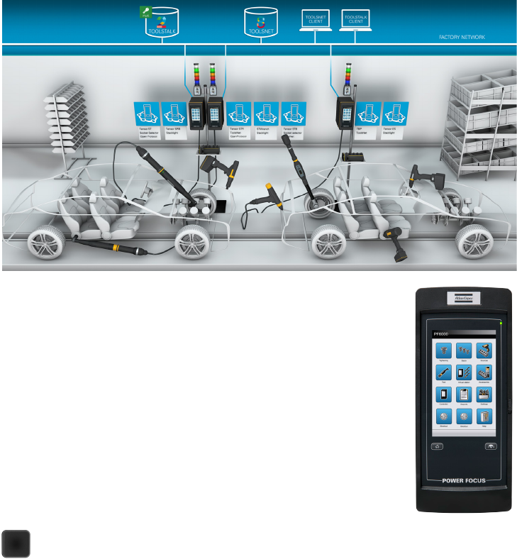
The core Power Focus 6000 systems consist of the following parts:
• Power Focus 6000 controller
• Intelligent Application Module (IAM)
• Tensor STR tool
• Tensor STR cable
• Accessories and communication interfaces
In the image below you can see how these different parts fit together as a
system in a typical customer environment.
Power Focus 6000 Controller
Power Focus controllers are recognized around the
globe for their outstanding tightening capabilities. The
platform meets the need to enhance error-proofing,
connectivity and flexibility, and is the first to introduce
software ergonomics to the industry. This won the
Power Focus 6000 the prestigious Red Dot design
award in 2012. Learn more about the functionality
of the software or the hardware connections in the
respective chapter.

POCKET GUIDE TO POWER FOCUS 6000 SYSTEM
7
Intelligent Application Module (IAM)
The intelligent Application Module (IAM) stores all the
• Tightening results
• Events
• Configuration
• Logs
• Software
Carry all information in the palm of your hand and transfer it easy from one
controller to another. The module is located on the inside of the door to the
controller and is available in three different versions:
• IAM Critical control
• IAM Process control
• IAM Process+ control
For a complete overview of the included functionality please see respective
chapter.
The Atlas Copco Tensor STR tool is a complete tool designed to work with
optimal performance together with the Power Focus 6000 controller.
Tensor STR
This Tensor power tool is a result of years of research and development to
improve productivity and quality without compromising ergonomics. Major
ergonomics improvements have been made possible by using the latest and
greatest technology available.
Tensor STR Cable
Atlas Copco has been producing assembly tool cables
since 1987 and has unrivaled experience in the
field. Flexibility and durability have steadily
improved since the introduction of the
company’s first generation cables,
resulting in today’s optimum
cable performance.
Atlas Copco’s flat-cable
design combines
maximum flexibility
(for access to difficult
applications) with

POCKET GUIDE TO POWER FOCUS 6000 SYSTEM
8
maximum durability.
Accessories And Communication Interfaces
The system connects perfectly to accessories and communication interfaces.
Most handheld tools are supported and the Power Focus 6000 system
has full connectivity with our QIF offerings and software products such as
ToolsNet 8 or ToolsNet 4000 and ToolsTalk 2.
The system also communicates with interfaces such as Fieldbus, Open
Protocol or customer specific protocols, creating a seamless integrated
solution in the customer environment.
POCKET GUIDE TO POWER FOCUS 6000 SYSTEM
9
POWER FOCUS 6000 HARDWARE
Power
Power Focus operates on a single-phase 115 or 230 VAC line voltage.
Power rating 1500 W
Line voltage
100-120 / 200-240 VAC (50-60 Hz) Power Focus has a function for sensing the
line voltage automatically. This means that the Power Focus automatically
switches to the voltage you connect to it.
Normal Environmental Conditions
The equipment is designed to be safe under the following conditions:
• Indoor use
• Altitude up to 2 000 m
• Maximum relative humidity 80% for temperatures
up to 31 °C decreasing linearly to 50% relative
humidity at 50 °C
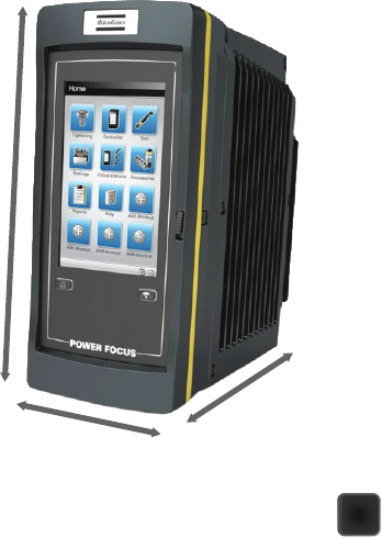
Size and Weight
Height: 316 mm (14.44 inches)
Width: 146 mm (5.75 inches)
Depth: 293 mm (11.54 inches)
Weight: 10.8 kg (23.81 pounds)
Display
7” resistive touch screen display
480 x 800 pixels
LED back light
Back light lifetime 70 000 hours
316 mm
146 mm
293 mm

POCKET GUIDE TO POWER FOCUS 6000 SYSTEM
10
Communication
• W-LAN wireless networking; IEEE 802.11a/b/g/n
compatible
• Bluetooth 2.1 (3.0 ready) + EDR (Enhanced Data
Rate) wireless technology
• 10/100 Mb/s Ethernet (RJ-45 connector)
Audio
Mono speaker
Ambient Temperature
5...+50 °C (41...122 °F)
Transient over voltages typically present on the mains
supply.
Connections
• 2 x 2.0 High Speed USB ports
• 2 x 10/100 Ethernet ports
• 4 x digital inputs (24V -15% +20%)
• 4 x digital outputs (24V ±20%, 1A)
• 1 x I/O bus
• 1 x aux. input (24V ±10%, 0.5A min)
• 1 x aux. output (24V, 1.5A max)
• 1 x emergency stop circuit class 3
• 2 x comm. ports (daisy chain)
• 1 x fan power output connector
• 1 x remote start switch
• 1 x Anybus CC connector
• 1 x IAM connector
• 1 x tool cable connector

POCKET GUIDE TO POWER FOCUS 6000 SYSTEM
11
IAM
With a memory capacity of 8 GB the IAM (Intelligent Application Module)
stores all the data for the Power Focus 6000: Licenses, results, events,
configurations, controller Firmware and service logs.
If needed, this data is easily transferred to other Power Focus 6000 by simply
removing and inserting the IAM.
Firmware updates are secure, as old firmware is kept available. This allows
you to quickly switch back to old firmware if needed.

POCKET GUIDE TO POWER FOCUS 6000 SYSTEM
12
POWER FOCUS 6000 SOFTWARE
Menu Overview
The menus is intuitive and easy to use. Navigate in the controller interface
by either tapping on a menu item or swiping across the display to scroll
through items. The web interface is identical to the controller display,
enabling configuration and programming via a web-browser on a connected
computer.
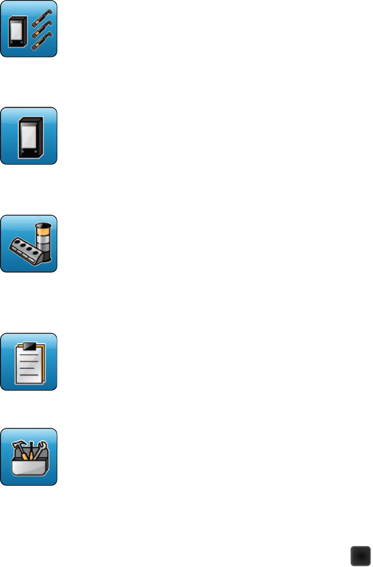
Tightening Menu
The Tightening menu lists the tightening program(Pset)
available for configuration, stored on the controller.
Batch Sequence Menu
The Batch menu lists the batch programs (Batch sequences)
stored in the controller.
Sources Menu
The Sources menu lists hardware accessories or functions
controlling the selection of a tightening program, for example
a Pset or a batch sequence. This is also where you configure
scanners you may be using with your tools.
Tool Menu
The Tool menu gives you access to information about the
connected tool, perform tool calibration, motor tuning, and set
up tool maintenance.
POCKET GUIDE TO POWER FOCUS 6000 SYSTEM
13
Virtual Station Menu
Tools and accessories are connected to the controller but
assigned to a virtual station. The task selection is also done in
the virtual station.
Controller Menu
The Controller menu makes sure you can administer and install
new controller software, view information about the hardware
devices installed on the controller, and export or import
configurations and reports.
Accessories Menu
The Accessories menu enables you to configure the internal
I/Os and the hardware accessories that can be used with
the controller such as I/O Expander, Stacklight, Operator
Panel, Socket selector and Scanner. The Scanner can also be
configured via other menus, such as the Sources menu.
Reports Menu
The Reports menu gives you access to historical tightening
results, events, and NOK ratio.
Settings Menu
The Settings menu is where you can set up the
controller on a LAN, configure PIN, language date and
time. This is also where you set torque unit to be used,
set tool alarms, configure Wi-Fi channels for wireless
tools, as well as configure how to display events.

POCKET GUIDE TO POWER FOCUS 6000 SYSTEM
14
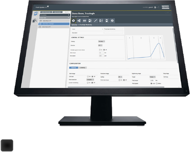
Basic Programming
The power focus 6000 tightening programs
need parameters such as target torque or
target angle to be set in order to perform a
tightening. Other settings – soft start, self
tap, and torque compensation – are optional,
just as setting which tightening strategy
to use. Monitor the tightening progress
by adding limits for torque, or specified
tightening angle.
In the general Pset settings you can set up
and manage the Psets by naming them and
making general tightening settings. Choose
tightening strategy, manual or quick prog
mode, and set the Pset target value.
To the right you can see a configured Pset
named Two step tight that uses a two step
tightening strategy set to the Target torque of
15 Nm
By clicking on “two step” in the strategy
box you can change strategy from two step
to TurboTight etc. Find more configuration
options by clicking on edit under tightening
parameters or loosing parameters.
For more information regarding
programming please use the power focus
6000 configuration guide with detailed
information on each menu item and the
configuration.

POCKET GUIDE TO POWER FOCUS 6000 SYSTEM
15
Open Protocol
The Power Focus 6000 enables communication
trough open protocol. The Atlas Copco Open
Protocol is a standard communication protocol
developed to facilitate communication
between our controllers and external parties in
the customer’s production processes.
Open Protocol is an interface for building
applications for remote control or data
subscription of controllers. It is platform
independent and can be implemented
on Linux, PLC, printers, and all Windows
platforms. The Open Protocol supports
Ethernet connection with the Power Focus
6000.
An Open Protocol message consists of
three parts; header, data field and message
end. Depending on type of communication,
a package includes the message and an
encapsulation before and after.
The MID, or message ID, is represented by a
four digit number (for example MID 0062 for
Vehicle ID Number upload). Each MID can have several revisions. Usually
a new revision is created when more data is included and the length of
the message needs to be increased. MID revisions are added to ensure
backwards compatibility.
For a full overview of what information, or MIDs (Message IDs) and
revisions, are supported with the Power Focus 6000 please see the Open
Protocol Appendix (picture above) provided in the Marketing and Support
Web Portal. The main value with Open Protocol is to provide a standard
and easy-to-use communication protocol. It can be set up in minutes and
integrated with your production processes in your plant. Through the years
“Open Protocol” has become an industry standard to communicate with
tightening equipment on assembly lines.

POCKET GUIDE TO POWER FOCUS 6000 SYSTEM
16
FUNCTIONALITY MANAGEMENT SYSTEM
Introduction
Atlas Copco Functionality Management System (FMS) is our new licensing
platform and it is a completely new way of delivering and administering
functionality available on Power Focus 6000 controllers. FMS is meant as
a way to simplify the way that functionality is added and removed from a
controller based on the actual needs on a station.
The customer portal is used for activating controller functionality, for getting
an overview of previous purchase orders and to map available features
to a USB license device or a functionality management system server. All
features that has been purchased is easily available from the customer
portal. This gives traceability of the functionality that has been bought and
also easy access in case a license has been lost.
Main benefits
• Flexible rebalancing
• Customizable and upgradable
• Instant delivery
• Trial licences
POCKET GUIDE TO POWER FOCUS 6000 SYSTEM
17
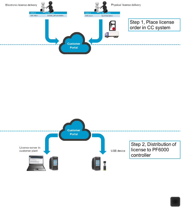
Order and distribute licenses to customer portal
There are two ways to distribute features and licenses to the customer
portal, electronic or physical delivery. The electronic delivery is made
automatically once the order is put in the local CC system and the features
is automatically linked to the customer account in the customer portal. The
physical delivery is carried out from PTD as a physical license paper from
PTD and a manual registration is required to link the features to the account
in the customer portal.
Distribution from customer portal
Once the licenses and features are delivered and linked to the customer
portal there are two ways to distribute the features to the controllers; a
server based solution (electronic way) and a non-network required solution
(physical way). The network based solution is meant for production facilities
where it is needed to re-balance and move functionality quickly and
efficiently between virtual stations. The physical way is the FMS USB license
device solution and is perfect for customers where an IP-based network is
not available and the need for rebalancing is not as big.
POCKET GUIDE TO POWER FOCUS 6000 SYSTEM
18
FMS Server based
The Atlas Copco FMS functionality is built into ToolsTalk from start making
it the best way to distribute virtual stations and features to the individual
controllers. ToolsTalk is also the best way of managing and programming
multiple controllers.
Start by uploading the capability request, received from Customer Portal, to
ToolsTalk in order to make the licenses available for distribution. After this is
done it is a very straight forward process to and features to the Power Focus
6000.
POCKET GUIDE TO POWER FOCUS 6000 SYSTEM
19
FMS USB device/non network based
The FMS USB license device is a great option for customers that do not
have the controllers networked and do not have any need for ToolsTalk
and plant level management of their controllers. With the Atlas Copco
USB license device it is possible to load and distribute virtual stations and
features to individual controllers.
After the USB device has been registered on the Atlas Copco customer
portal and the capability file has been downloaded, move the license file
to the USB device. The USB device will be used for transporting the virtual
stations and features to the controller. Plug in the USB to the controller that
needs to have additional virtual stations and features. After the device has
been inserted an icon will appear on the top right of the controller screen
or in the webHMI and by pressing this icon it is possible to add more virtual
stations and/or features to the controller.
When adding a virtual station and/or feature to the controller this means
that the amount of available functionality on the USB device will go down
based on what is added to the controller.
If a virtual station or a feature needs to be moved from a controller to
another one just plug in the same USB stick as the one that was used to add
it originally and move it back to the USB device. Now the device contains
this functionality and it can be moved to a different virtual station.

POCKET GUIDE TO POWER FOCUS 6000 SYSTEM
20
TIGHTENING STRATEGIES
Select tightening strategy by choosing the method for applying clamping
force (or preload) to the joint. Different joints require different strategies for
applying the desired clamping force and to minimize unwanted in-service
effects.
The Turbo Tight
®
strategy enables the option to use Manual programming or
Quick prog, see section Strategy. The Quick step, Two step, and Three step
strategies enable the choice of tightening towards a Target torque or a Target
angle value, see section Target.
All tightening strategies require that you set either Target torque or Target
angle value.
Turbo Tight
®
Tightening Strategy
Turbo Tight
®
is the default tightening strategy, designed to perform a very
fast and ergonomic tightening based on the tool’s maximum speed (Tool
max speed). This strategy only requires Target torque to be set in order to
perform the tightening. Depending on the joint properties, for example if the
joint is very stiff or very soft, a different tightening strategy might be needed.
Note! The Turbo Tight
®
strategy is only available when using the Tensor STR
tools.
Fine-tuning the Turbo Tight
®
Tightening strategy
If the Turbo Tight
®
strategy gives unwanted results, we recommend you to
take look at how the Rundown complete is set.
A Rundown complete set too high could give the Turbo Tight
®
strategy too
little time to work on the needed calculations in the Tightening step, and
result in an overshoot. The ambition should be to set the Rundown complete
as close to snug as possible. A Rundown speed set too high could also cause
the Turbo Tight
®
not to have enough time to work on the needed calculations
in the Tightening step resulting in an overshoot. This is even more important
if the joint is very stiff.
Reduced cycle times
Turbo Tight
®
optimizes the tightening speed to achieve the fastest possible
tightening maintaining reliable accuracy. The results are:
• Possibility to remove bottlenecks,
• Possibility to rebalance assembly lines due to increased
cycle rate,
• Less heat development, a cooler tool during operation.
POCKET GUIDE TO POWER FOCUS 6000 SYSTEM
21
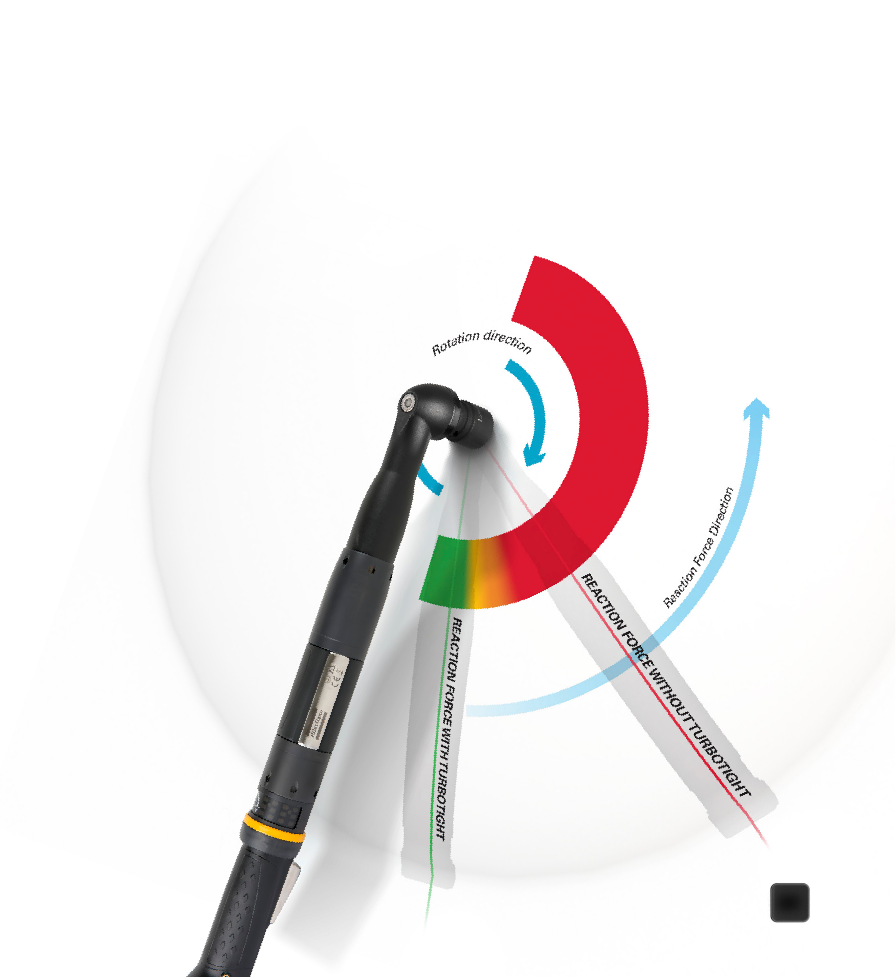
Reduced reaction force
With optimized tightening speed, the torque builds up faster,
reducing the amount of force transmitted to the operator’s hand.
The results are:
• Reduced operator fatigue and risk of injury,
• Improved operator comfort during tightening,
Reduced need for reaction absorbing devices in certain situations, giving
less cost and reduced tool weight.
Easy set-up
Turbo Tight
®
is designed to be extremely easy to set up. In most cases, you
just need to set the target torque and you’re ready to go. Exceptions are
discussed in the following chapters. In such cases please contact your local
Atlas Copco Tools representative for support. The results are:
• Time savings during set-up,
• Less time and money spent on training,
Work rotation enabled.
POCKET GUIDE TO POWER FOCUS 6000 SYSTEM
21

POCKET GUIDE TO POWER FOCUS 6000 SYSTEM
22
Sustainability
Using Turbo Tight
®
results in shorter tightening cycles. This in turn
means less heat development and a cooler tool. It also helps to reduce
energy consumption with 10 % and prolong tool lifetime in high-cycle
environments. In general the losses during a tightening can be reduced by
speeding up the tightening phase, but remember: the big savings come
from standby.
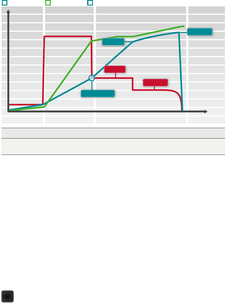
How are cycle times reduced?
Turbo Tight
®
controls the motor speed to achieve the fastest possible
tightening without excessive overshoot. Comparing it to a traditional Two
Step strategy, Turbo Tight
®
runs faster for a longer period.
How is reaction force reduced?
Turbo Tight
®
uses the tool’s mass moment of inertia to reduce the reaction
force transmitted to the operator. The increased control of the motor in
combination with the fast dynamic regulation enables the tool to minimize
the reaction force from the tightening.
How come set-up is so easy?
Turbo Tight
®
is a strategy that controls the motor speed based on the actual
torque rate and the remaining torque of the joint. Since all these parameters
are dynamically calculated during the tightening, the only user input
required is the target torque.
How does Turbo Tight
®
provide energy savings?
Atlas Copco has been ISO 14001 certified since 2010, ensuring the planning,
execution, control and optimization of continuous improvement processes
for all Atlas Copco Industrial Technique products. If we compare the energy
consumption of a Power Focus 4000 running a Tensor ST tool with a Two
Step set-up, with the energy consumption of a Power Focus 600/6000
running a Tensor ES/STR tool with Turbo Tight
®
, we get the following result.

POCKET GUIDE TO POWER FOCUS 6000 SYSTEM
23
Target Speed
Pause Time
Target Torque
First Torque
Rundown Complete
First Speed
Start Stop
TIME
TORQUE/TIME ANGLE/TIME SPEED/TIME
Rundown Tightening
Two Step Tightening Strategy
The two step tightening strategy is very similar to the Quick step strategy
with the exception that it adds a small time delay between the first step and
the final step, to further counteract short-term relaxation effects in the joint.
Fine-tuning the Two Step Tightening strategy
When the First target is reached the tool will make an immediate stop for a
specified time before it continues with the final step. The First torque value
and the Pause time should be chosen to improve ergonomics for hand-held
tools.
Parameter Description Default Value
First torque Target torque for the first step
First speed Target speed for the first step
Pause time Time between first and second step 50ms
POCKET GUIDE TO POWER FOCUS 6000 SYSTEM
24
Quick Step Tightening Strategy
Quick step tightening strategy is used to reduce the joint’s preload scatter by
adding an initial step with a given torque and speed, and then reducing the
target speed in the final step.
Start Stop
TIME
TORQUE/TIME ANGLE/TIME SPEED/TIME
Rundown Tightening
Rundown Complete
Target Speed
First Speed
First Torque
Target Torque
Parameter Description Default Value
First torque Target torque for the first step
First speed Target speed for the first step
POCKET GUIDE TO POWER FOCUS 6000 SYSTEM
25
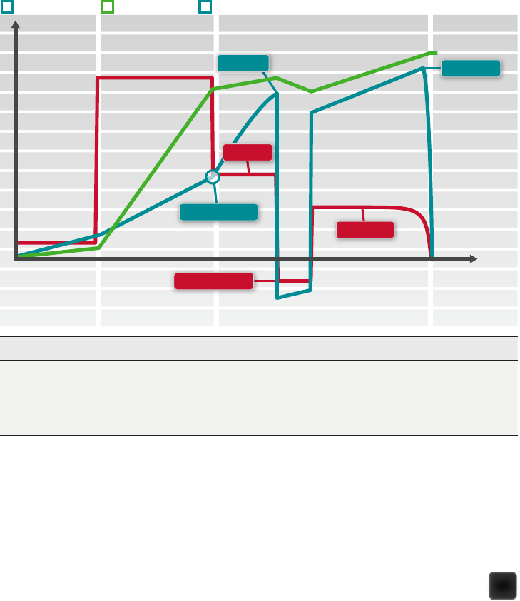
Three Step Tightening Strategy
The three step tightening strategy adds a loosening step between the
first step and the final step to overcome short-term relaxation effects due
to embedment, and reduce preload scatter. This is sometimes called to
condition the joint. This can be useful in, for example, joints with many
adjoining surfaces and will have greater effect on new parts than on reused
ones due to the smoothening of surfaces which will reduce embedment.
Conditioning the joint is done by tightening the first step to a given torque,
First torque, and then releasing the load by turning the nut a specified
Conditioning angle and then retightening the nut to its Target torque.
Target Speed
Conditioning Speed
Target Torque
First Torque
Rundown Complete
Start Stop
TIME
TORQUE/TIME ANGLE/TIME SPEED/TIME
Rundown Tightening
First Speed
Parameter Description Default Value
First torque Target torque for the first step
First speed Target speed for the first step
Conditioning speed Target speed during the conditioning step
Conditioning angle Angle to turn the socket during the conditioning step 180°
POCKET GUIDE TO POWER FOCUS 6000 SYSTEM
26
Rotate Strategy
The rotate strategy is primarily a strategy for testing and demo purposes.
When letting the tool rotate in free air, it will turn the socket to the specified
angle using the lowest torque possible.
Target Torque Limits
By setting the Target torque limits is it possible to discard a tightening,
should the torque result not fall within the specified torque limits. A Torque
set too high can cause the bolt to deform or break as a result of passing the
yield point. Not enough torque can end up with the clamping force not being
enough to withstand the forces for which the joint is designed.
Parameter Description Default Value
Target speed Target speed for the Rotate Strategy
Target angle Angle to turn the spindle 360°
Start Stop
TIME
TORQUE/TIME ANGLE/TIME SPEED/TIME
Rundown Tightening
Target Torque
Max Torque
Rundown Complete
Min Torque
POCKET GUIDE TO POWER FOCUS 6000 SYSTEM
27
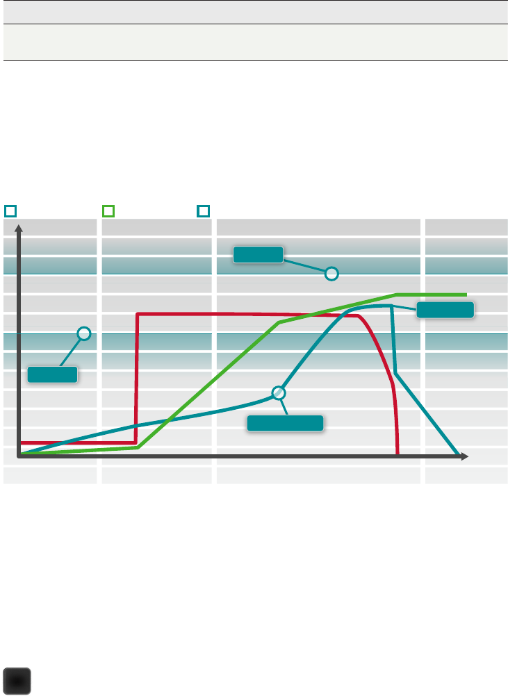
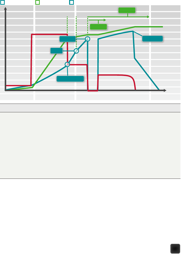
Target Angle Limits
With Target angle limits set, it is possible to monitor if the nut is turned to
the desired angle during the tightening.
Start Stop
TIME
TORQUE/TIME ANGLE/TIME SPEED/TIME
Rundown Tightening
Target Torque
Angle max
Angle min
Torque
First target
Rundown Complete
Parameter Description Default Value
Angle limits Choose the section of the tightening in degrees, where to
monitor the angle.
Off: No limits are checked.
From Rundown complete: The monitoring window is set from
when the Rundown complete torque is reached.
From Torque: The monitoring window is set from when the
specified torque value is reached. Torque must be greater than
First torque.
From First target: The monitoring is set from when First target
is reached. This option is not available if TurboTight is chosen.
Target speed
<From torque> Torque value from where angle limits are set Target speed
Angle min Angle value for lower angle limit 90°
Angle max Angle value for upper angle limit 720°

POCKET GUIDE TO POWER FOCUS 6000 SYSTEM
28
Torque Compensation
By using torque compensation, the actual clamping force applied to the joint
can be better determined and the scatter in the applied clamping force can
be reduced.
The torque compensation point is set by using a previously specified angle
from Rundown complete and then calculating a value for the torque used
during rundown. When creating the preload in the bolt, this is compensated
for by adding the torque value calculated in the torque compensation point,
to the Target torque.
Stop Stage
The Stop stage terminates the tightening so that the socket can be released.
Parameter Description Default Value
Torque compensation Enables adjusting Target torque for torque used in the
rundown stage.
Off: No compensation made.
On: Manually sets the Torque compensation point.
Off

POCKET GUIDE TO POWER FOCUS 6000 SYSTEM
29
Soft Stop
Soft stop makes the tightening stop in a more ergonomic fashion. Avoiding
the tool to stop within the time interval of 50-300 ms, since it is known to
create an uncomfortable stop.
Parameter Description Default Value
Soft stop Turns the soft stop on or off.
Off: No soft stop is used.
On: Soft stop is activated. When target torque is reached the
tool speed is immediately decreased to 75%. Then the speed
is decreased to zero in at most 40 ms.
Off
POCKET GUIDE TO POWER FOCUS 6000 SYSTEM
30
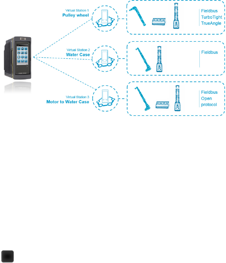
VIRTUAL STATIONS
Introduction
The Virtual Station is the enabler of your assembly. It controls the tool,
the communication and the accessories in your assembly station.
Controlling multiple tools, working with virtual station gives you less cable
management, less network connections and less hardware components.
You will gain increased flexibility with increased rebalancing speed in your
production.
The Virtual Station keeps all information about your assembly process,
giving you an instant overview of what is going on in the production.
Tool Control:
Making sure your tool
is performing correct
tightenings for your
assembly.
• Pset selection
• VIN handling
• Batch sequence
control
Communication
Control:
Communicating for
easy and seamless
integration with your
production systems.
• Open Protocol
• Fieldbus
• Customer Protocols
Accessory Control:
Taking care of multiple
accessories per virtual
station.
• Stacklight
• Socket selector
• Digital I/O
POCKET GUIDE TO POWER FOCUS 6000 SYSTEM
31
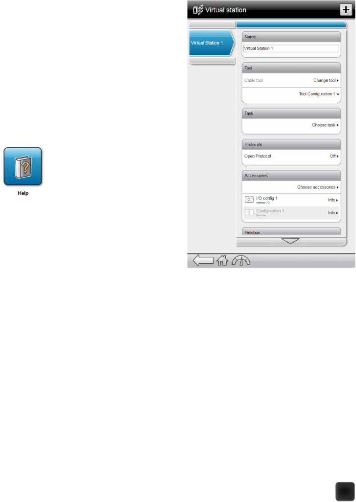
Setting up a Virtual Station
In every IAM there is at least one
Virtual Station included. More virtual
stations can be added using the
FMS function in ToolsTalk2 or by pre-
configured IAMs.
When an additional virtual station has
been added a plus sign will appear
in the in right corner in the Virtual
Station menu. When all Virtual Stations
available has been added the plus sign
will disappear.
In the help menu there is information
on how to configure and setup the
Virtual Station. All the help material
can be downloaded in PDF from the
controller using the WebHMI.
Key Benefits
• Easy to set up
• QIF accessories connected in total
• The same accessory can’t be repeated in the same Virtual Station
(i.e. 2 stacklights on the same Virtual Station)
• Works with existing accessories (socket selectors, stacklight, operator
panel, etc.)
• Copy-Paste psets, Virtual Station configurations (ToolsTalk 2)
• 1 job in different Virtual Stations
• Excellent user interface
• Excellent graphical concept and very easy to configure
• Less wiring complexity

POCKET GUIDE TO POWER FOCUS 6000 SYSTEM
32
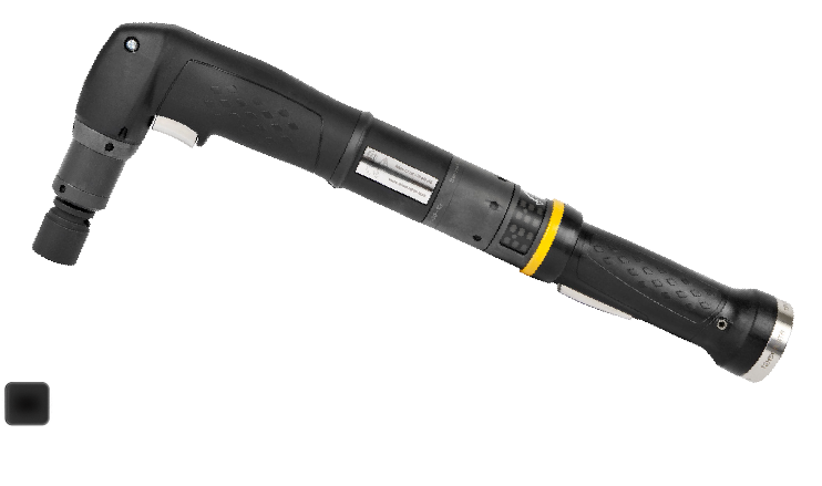
STR TOOL
Overview
Tensor STR tools can be powered by the Power Focus 4000 and the Power
Focus 6000 controllers. The full capacity of the tool is available when
controlled by the Power Focus 6000.
When running on a Power Focus 4000:
• Tools are generally running on a slightly lower max
speed around 90% of maximum.
• Turbo Tight
®
is not available when running on a
Power Focus 4000.
• When connecting the ETT tool to a Power Focus
4000 the front trigger can only be programmed to
act as a safety trigger.
• When connecting STR tools to Power Focus 4000
the ST tool cable should be used.
The tool has been designed for a very high level of reliability and durability.
Heat transfer has been improved a lot compared to previous generations.
The heat is more efficiently transferred over the tool, keeping the hot areas
cooler. This increases the life length of grease and in the long run the
internal mechanical parts. IP54 classification (ETV and ETD) is another factor
that highly contributes to the increased durability, since the tool is better
sealed and protected for intrusion of dust and fluids.
ETV and ETD are the full featured STR tools. ETT is missing the IP
classification and gyroscope. ETP is of an older base design but offers the
same level of connectivity and accuracy as the most recent tools.

POCKET GUIDE TO POWER FOCUS 6000 SYSTEM
33
Models
Tool Modules
The STR concept uses modules to increase quality and flexibility. Different
modules are combined with new models and all the motors have the same
diameter so modules can be interchangeable between different sizes.
Due to matching electronics and hardware tested as a separate unit, the
module concept also makes it easier to replace parts. All electronic modules
use connectors to make assembly and service fast and simple, no soldering
required.
Handle module
The handle module is common for all STR ETV and ETD models. It includes
the main electronic board, the board and its components are molded into
plastics for extra protection. The module also carries the vibrator, which can
be programmed to give feed back to the operator.
The gyroscope is another key component in the handle as it can sense
movements of the tool down to 1 degree.
The cable connection has a new generation of pins and sleeves that
increases the wear resistance considerably compared to previous
generations.
The trigger is easily removed for better accessibility during cleaning.
HMI
The HMI module is where the tool and operator interact with each other. The
module has LED lights – yellow, green or red. There is also a blue LED and
a tightening direction indicator. The reverse ring is lockable and the module
also includes a speaker that can send sound signals to the operator.
The standard HMI and EHMI is available with or without a button on the
reverse ring.
ETD ETV
ETPETT
POCKET GUIDE TO POWER FOCUS 6000 SYSTEM
34
Motor
In the STR ETV/ETD range all motors have the same diameter. More
powerful motors are made longer.
Focus has been to increase the robustness of the motor. For example the
bearing houses are made stronger and in Aluminum. A new insulation
system has made it possible for the intermediate shaft to be made with
fewer parts and without plastic material.
Motor rotation speed is higher than on ST tools when running with a Power
Focus 6000.
RFID tag is included in the motor module. It will be determined at a later
point what will be included in the chip.
Torque transducer
The torque transducer is a delicate part that should not be replaced if faulty.
The transducer shows a very accurate reading from 100% down to 20% of
the nominal torque. STR range is improved so that disturbance from the
motor has less effect on the signal, making the reading more exact resulting
in an improved tool accuracy.
Gears and Angle head
Planet gears and angle gears are all made of a special steel that is specially
developed for Atlas Copco.
The angle head gears are spiral cut for maximum accuracy and durability,
larger angle heads are prepared for attaching a reaction plate.
ETT front part
The ETT front part differs from other tools in how the transducer is placed
after the angle gear and attached to the output shaft. This gives the ETT tools
an accuracy of 2,5% over 3s.

POCKET GUIDE TO POWER FOCUS 6000 SYSTEM
35
Accessories (attached to the tool (ETV/ETD))
The tool has two connections for accessories, making it possible to combine
a number of different combinations of helpful accessories.
Accessory Function
Lever trigger 135deg
Trigger that is offset for alternative grip, acting as
“button”.
Lever trigger?
Same as lever trigger 135 deg but straight, acting as
“button”
Button Button for sending impulse on st bus.
Headlight Lamp to illuminate tolls work area.
2D scanner Scanning 2d codes (3d > qr)
Selector ring (button) Button on ring, acting as “button”
Tool leds Led card with leds to send operator feedback.
Ehmi Display with 3 buttons
Tls tag

POCKET GUIDE TO POWER FOCUS 6000 SYSTEM
36
Certifications
EC declaration
EC declaration can be found in the
Safety information appended to
the product. The declaration states
responsible manufacturer and shows
European product directives and
harmonized standards.
European product directives – This
is the European Union product
legislation. The directives contain high
(and low) level requirements on the
product and procedures that relate to
the product during its life-cycle. The
requirements mainly concerns safety.
The directives applicable to STR are:
2006/42/EC – The machinery directive
2004/108/EC – The EMC directive
(ElectroMagnetic Compatibility)
1994/9/EC- The ATEX directive (Explosive Atmosphere)
Harmonized standards
The directives set out high level product requirements. These may be
difficult to interpret. A harmonized standard is generally a safety standard
that has been approved by the European Union authorities as compliant
with a product directive. In practice, the standards are used as the means for
complying with the law. E.g.
EN 61010-1:2010 Safety requirements for electrical equipment for
measurement, control and laboratory use - Part 1: General requirements.
EN 61000-6-2:2005 Electromagnetic compatibility (EMC) - Part 6-2: Generic
standards - Immunity for industrial environments.
En 61326-1:2006 Electrical equipment for measurement, control and
laboratory use- EMC requirements Part 1: General requirements.
Other directives
The EC declaration concerns directives required for CE marking. However,
there is more legislation that needs to be considered. E.g.
Information concerning Restriction of Hazardous Substances (RoHS) - This
product and its information, meets the requirements of the RoHS Directive
(2011/65/EU).

POCKET GUIDE TO POWER FOCUS 6000 SYSTEM
37
Information concerning Waste of Electrical and Electronic Equipment (WEEE)
- This product and its information, meets the requirements of the WEEE
Directive (2012/19/EU), and must be handled according to the directive.
IP 54 protection
The STR tools are certified for IP protection level 54. The level of protection
will prevent foreign particles and fluids from entering the tool. This will make
the tool more durable than previous generations, due to less contamination
of internal parts.
IP54 – The first number marks the protection level for dust. Level 5 = “Ingress
of dust is not entirely prevented, but it must not enter in sufficient quantity
to interfere with the satisfactory operation of the equipment; complete
protection against contact (dust proof)”. The second number states the
protection level for water intrusion. Level 4 = “Water splashing against the
enclosure from any direction shall have no harmful effect”.
Note! ETT and ETP STR tools are not IP tested and do not meet IP54
requirement.
Service/Maintenance Intervals
Overhaul and preventive maintenance is recommended at regular intervals
once per year or after maximum 250.000 tightening depending on which
comes first. More frequent overhaul may be needed if the machine is used
in heavy-duty operations.

POCKET GUIDE TO POWER FOCUS 6000 SYSTEM
38
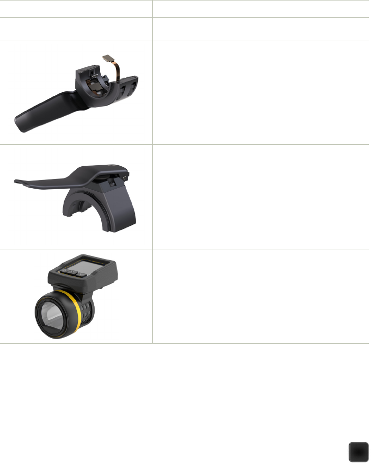
STR TOOL ACCESSORIES
The STR tool can utilize two different accessories at a time.
The accessories consist of two halves, upper and lower and can be
combined in different ways, for example a scanner and headlight can
be put together on the front bus.
Used for reading bar codes or QR codes, connects to one of
the tool bus slots.
Button for sending instructions from the operator connects to
one of the tool bus slots.
Used to illuminate the work piece, connects to one of the tool
bus slots.
Suspension that allows the tool to rotate, used when attach-
ing the tool to a balancer.
POCKET GUIDE TO POWER FOCUS 6000 SYSTEM
39
Mounting Bracket Used for fixturing the tool
Protection Cover
Protection to avoid scratches caused by the tool in sensitive
applications.
Trigger that is offset for alternative grip connects to one of
the tool bus slots.
Shorter lever that can be used as a safety trigger connects to
one of the tool bus slots.
EHMI, small display that can show information about the
tightening and also acts as a Pset selector connects to one of
the tool bus slots.
Local customization
The tools can easily be fine-tuned to fit the operator preferences or the
application by adding tools accessories. The standardized sizes, fits a wide
range of Atlas Copco tools.
POCKET GUIDE TO POWER FOCUS 6000 SYSTEM
40
CABLE MANAGEMENT
Cables are used in conjunction with all Atlas Copco tools and assembly
equipment, including: hand held tools, fixtured hand tools or when spindle
”motors only” are provided for incorporation into various types of machine
automation.
As with many industrial systems, cables are a main failure point – especially
in applications where the cables are subject to repetitive motion. Atlas
Copco has the knowledge to help the customer find effective solutions to
their facilities unique cable needs.
In the case of fastening equipment, cables connect the following functions:
• Power supply
• Controller
• Nutrunner
• Accessory
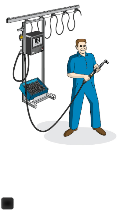
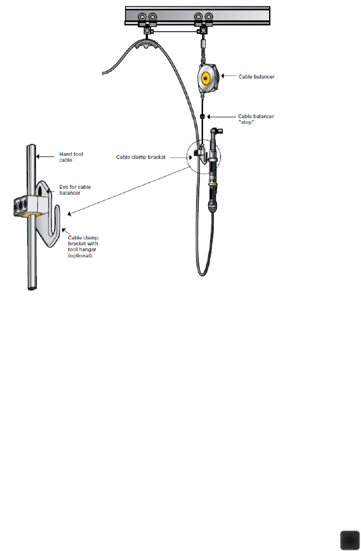
With a proper cable management
you will increase the life of
the cable and reduce the risk
operators falling over them. In
example, using a cable balancer
helps to manage the excess cable
when the tool and cable are not
extended.
POCKET GUIDE TO POWER FOCUS 6000 SYSTEM
41
Use of a cable clamp bracket
This clamp bracket can be attached to a hand tool cable and then be attached
to a cable balancer. When located properly on the tool cable, the cable
balancer will keep the cable off the floor. A hook is provided as a place to
“rest” the tool and may be used with or without a cable balancer to “rest”
the tool when the cable is spread over the cable shoe.
POCKET GUIDE TO POWER FOCUS 6000 SYSTEM
42
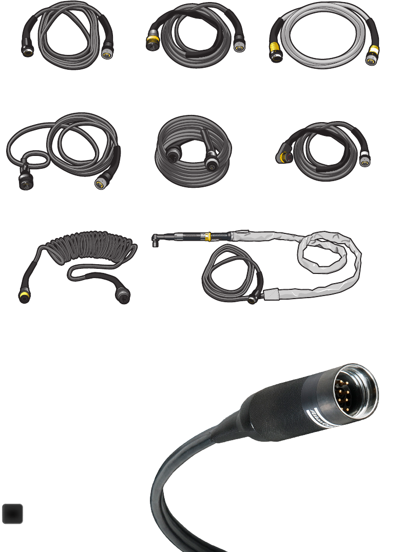
Types of cables available
Various types of cables are available from Atlas Copco to suit all kinds of
applications, as illustrated below.
Tensor STR cable
Tensor STR cable has the same functionality but
different interfaces towards the controller.
However, they have the same interface
towards the tool.
Tensor S Extension Cable.
Tensor S Extension Cable with loop. The
cable loop makes cable even more flexible
if the tool is used in small circles.
Tensor ST Spiral Cable.
Tensor S Extension Cable for
fixtured applications.
Tensor S Cable with 90°connector.
Angle connection cables for
applications where space does not
allow the use of normal cables.
Cable cover for workpiece surface protection.
Tensor S Tool Cable.
Tensor ST Tool Cable

POCKET GUIDE TO POWER FOCUS 6000 SYSTEM
43
Flat cable for greater durability
Atlas Copco has been producing assembly
tool cables since 1987 and has unrivaled
experience in the field. Flexibility and
durability have steadily improved since the
introduction of the company’s first-generation
cables, resulting in today’s optimum cable
performance. Atlas Copco’s flat-cable design
combines maximum flexibility (for access
to difficult applications) with maximum
durability. No other manufacturer can offer
such a powerful combination of flexibility and
performance.
Smaller bending radius for greater accessibility.
Atlas Copco engineers its tool cables to withstand consistent and long-
term flexing. Cable size (diameter) is the most
critical factor in terms of flex life. The best
way to reduce fatigue affecting the internal
cable conductors is to keep cable thickness to
a minimum. Atlas Copco’s flat-cable design is
just under half the thickness of a comparable
“round” cable, offering an exponential gain
in flex life. When it comes to durability and
flexibility, the Atlas Copco cable is unique.
Innovative ‘Cable Twist’ design
The most critical area for an assembly tool cable is at the point of maximum
flex – generally close to the tool connection point. Atlas Copco’s “Cable
Twist” design spreads the flex load over a greater distance, to minimize flex
in the critical area. This patented flat-cable “twist” design is unique to Atlas
Copco.
Round
Flat
Tensor Round

POCKET GUIDE TO POWER FOCUS 6000 SYSTEM
44
Centralized strain relief to prevent lead damage
The flat-cable design features a Kevlar-reinforced core, to absorb the
tensile loads to which cables can be subjected in tough applications. When
subjected to high tensile loads, this centralized load-relief Kevlar core also
prevents cable leads being damaged or compressed. For maximum signal
integrity, the flat cable design also ensures optimum separation of high and
low voltage conductors.
For more information regarding cable management please look in the cable management
pocket guide (9833 1640 01). In this pocket guide you will find more information regarding cable
management for fixtured and hand held tools and check points before, during an
Low
Kevlar
High

POCKET GUIDE TO POWER FOCUS 6000 SYSTEM
45
FIELDBUS
Fieldbus is an industrial network system
for real-time distributed control. It is a way
to connect instruments in a manufacturing
plant, for example Power Focus controllers.
Fieldbus works on a network structure which
typically allows daisy-chain, star, ring, branch,
and tree network topologies. The fieldbus
requires only one communication point at
the controller level, and allows hundreds of
analog and digital points to be connected at
the same time. This reduces both the length
of the cable required and the number of
cables required. Furthermore, since devices
that communicate through fieldbus require a
microprocessor, multiple points are typically
provided by the same device. Some fieldbus
devices now support control schemes such
as PID control on the device side instead of
forcing the controller to do the processing.
The Power Focus 6000 currently (release 2.1)
supports three different fieldbus types:
• DeviceNet
• EtherNet/IP
• ProfiNetIO
You can set up the fieldbus parameters using Tool Talk 2. For a full overview
of how this is done, please see the user guide for Tool Talk 2.
In short, the value of using a fieldbus communication is to have a real-time
control over multiple controllers in a standardized way in your production
plant.
Please note that there are a couple of fieldbus types available in the Power
Focus 4000 that are not yet implemented on the Power Focus 6000 platform.

POCKET GUIDE TO POWER FOCUS 6000 SYSTEM
46
TOOL TALK 2
Tool Talk 2 is developed from the ground up, to support the new multi-
controller concept delivered in the Power Focus 6000. When the old version
of ToolsTalk was a software tool to configure a single controller
– Tool Talk 2 takes controller programming to a whole new level by making it
easy to manage and program multiple controllers.
User Authentication
Tool Talk 2 supports user authentication in the application from the start.
This functionality makes sure that no one, except approved users, can make
changes to controllers and tightening programs. The second benefit of this
is that customers have full traceability of changes to tightening programs
in the application. Every change to a tightening program is logged in the
application, making it possible to see all the changes that have been made
to a program during its life cycle and also exactly which user that made the
change. If a problem occurs in production it is easy to identify the person
that made the change and by this it is possible to find the reason for the
change.
• Full change traceability of tightening programs
• Ensure that only approved users can make changes
to tightening programs
• Know which user is making changes on a controller
Plant Structure
The plant structure in ToolsTalk 2 makes it possible to organize all Power
Focus 6000 controllers into a structure that resembles the structure in the
plant. This makes it quicker and easier to administer controllers throughout
production.
• Organize controllers according to the layout in the
plant
• Quickly find controllers and tightening programs
that needs to updated
• Get an overview that everything is running as it
should

POCKET GUIDE TO POWER FOCUS 6000 SYSTEM
47
Multiple Controller Upgrade
ToolsTalk 2 leverages on the dual memory area functionality of the Power
Focus 6000, by making it possible to upgrade multiple controllers at
once just by one click. When doing an upgrade ToolsTalk 2 loads the new
controller firmware into the Power Focus 6000 controller but it does not
activate the new software until you are ready. When then time has come to
use the new software, it is possible to make the switch from ToolsTalk 2. It
also increases safety since you can switch back to the previous version of
the software just as easily if needed.
• Upgrade multiple controllers directly from the
application
• See exactly which software that is running on all
controllers in production
• Switch between software versions running on
the controller by selecting the desired preloaded
software versions.
Controller Programming
ToolsTalk 2 makes controller programming easier than ever before. All the
tightening parameters are available from a single view, creating a great
overview of the complete setup. When setting up or updating a tightening
program in ToolsTalk 2 all the changes are saved locally in the database of
the application, meaning no changes are stored on the controller initially.
This makes it possible to make all the needed changes before saving
anything to the controller. Thanks to this all the parameters can be adjusted
and verified before actually saved on the controller.
ToolsTalk 2 also saves all version of the tightening programs in its database,
making it possible to go back to a previous version of a program in case
there are any problems or concerns with an update that has been made.
• Great overview of all tightening parameters
• Possibility to setup all parameters before saving on
the controller
• Easily go back to a previous version of a program

POCKET GUIDE TO POWER FOCUS 6000 SYSTEM
48
TOOLSNET 8
ToolsNet 8 is the next generation data collection and production analysis
software from Atlas Copco. In order to achieve the highest value in the
application the whole web application was rebuilt from scratch, making it
possible to leverage on new modern technologies. In the base ToolsNet 8
still has the reliable data collection that has been developed by Atlas Copco
for almost 15 years.
With the new additions of the dashboard, statistical center and the tool
center we make sure the value of the product is increased to an even higher
level.
Reliable Data Collection
Collecting data is easy when using an Atlas Copco controller in combination
with ToolsNet 8. After ToolsNet 8 is installed just set the IP-address of the
ToolsNet 8 server in the controller and it immediately starts sending over
tightening results. ToolsNet 8 also supports competitor tools through
ToolsNet 8 Open Protocol. With Open Protocol it is important to check with the
competitor regarding what functionality they have implemented on their side.
Simple setup in combination with Atlas Copco controllers
Data buffers both on the controller itself but also on the ToolsNet 8
application server in case the database goes down which ensure high
security.
Simple Data Analysis
In ToolsNet 8 the reports have been further enhanced, meaning more of the
daily work and analysis can be done directly in ToolsNet 8.
• Possibility to filter directly in the reports
• All users can choose what fields they want to see in
their reports
• Possibility to group data directly from the reports
• Save favorite reports which increases the efficiency
when working with the application
• Export reports to Excel for further analysis
• Get detailed information about tightening results
• Simple access to all traces

POCKET GUIDE TO POWER FOCUS 6000 SYSTEM
49
Production Alarms
ToolsNet 8 makes it simple to setup alarms based on specific controller
events in production. All the events that are available in the Power Focus
and the PowerMACS controller can be setup as events in the notification
center of ToolsNet 8. After it has been setup, an email will go out to the
configured receiver as soon as there is an event, making it possible to
cut down response times and thereby reducing the time it will take to fix
production problems.
• Reducing down-time thanks to direct notification
about production problems
• Simple setup of notification means customers will
use it
Alarms based on statistical trends. Find material problems or process
problems automatically.
Dashboard
The dashboard gives a direct overview of the production in the plant. Every
user can configure the dashboard in a way that best suits their needs. For
example, if a user wants to focus on statistics it is possible to setup multiple
widgets showing SPC data in real-time for specific applications making it
easier to catch problems related to material or process problems.
Available dashboard widgets are:
• Top NOK applications: Shows the applications with
the highest failure rate for a configured part of the
tool structure.
• Running SPC: Shows the real-time X-bar and range
charts for a configured application.
• Tool maintenance: Shows the tools that need service
or calibration, from all the Power Focus tools in
production (currently only support Power Focus
W10.6+ and W14 controllers).
• Latest results: Shows an overview of the latest results
from the chosen part of the of the tool structure.
Traceability
ToolsNet 8 greatly increases the traceability in our customer’s production.
With the application it is possible to find a specific product and ensure that
all tightening have been done correctly by for example analysis the traces.
• Get all results based on a time interval
• Get all results based on a specific VIN number
• Find statistical deviations based on all tightening results.

POCKET GUIDE TO POWER FOCUS 6000 SYSTEM
50
Tool Service Information
ToolsNet 8 automatically collects information about all the tools in
production making it possible to find tools that have not been serviced in a
long time or tools in need of calibration. You can also find information about
software version of connected tools and the number of rundowns that have
been performed since the last service.
• Keep service log of all tools in production
• Get statistics on how a tool is performing on a
specific application
• Find information about tool software versions
• Get information about last service and calibration
of a specific tool
• Locate to which controller a tool is currently
connected by serial number
• Manage custom tool serial numbers in the plant

POCKET GUIDE TO POWER FOCUS 6000 SYSTEM
51

COMMITTED TO SUSTAINABLE PRODUCTIVITY
www.atlascopco.com
9833 2074 01 2016:1
