
Specification
Open Protocol
Atlas Copco Industrial Technique AB
9836 4415 01
Specification Release 2.8.0
Copyright Atlas Copco Industrial Technique AB
Note! This manual can be altered without further notice.
For further information log in to Atlas Copco www.atlascopco.com

Contents
1 (285)
1 Introduction ............................................................................................................ 11
1.1 Revision history ................................................................................................. 11
1.2 Referenced documents ..................................................................................... 16
1.3 Protocol and Specification Versioning ............................................................... 16
1.4 Terminology ....................................................................................................... 18
2 Using Open Protocol ............................................................................................. 21
2.1 Communication ................................................................................................. 21
2.1.1 Ethernet protocol ................................................................................................................................... 21
2.1.2 Serial protocol ........................................................................................................................................ 22
2.2 Message structure ............................................................................................. 25
2.2.2 Header ................................................................................................................................................... 26
2.2.3 New MID numbers use from OP 2.0 ...................................................................................................... 27
2.2.4 MID with both ASCII and binary data from OP 2.0 ................................................................................. 28
2.2.5 Sequence number functionality from OP spec. 2.0 ................................................................................ 28
2.2.6 Message linking functionality from OP spec 2.0 .................................................................................... 30
2.3 Static Data Field use ......................................................................................... 30
2.3.1 Static Data field implementation rules .................................................................................................... 31
2.4 Variable data field use from OP spec 2.0 .......................................................... 32
2.4.1 Message End ......................................................................................................................................... 33
3 Implementation guidelines and Communication ................................................ 34
3.1 Application Startup messages exchange ........................................................... 34
3.2 Message acknowledging methods .................................................................... 34
3.2.1 Application Level acknowledging method .............................................................................................. 34
3.2.2 Link Level acknowledging method from OP spec. 2.0 ........................................................................... 36
3.3 Establishing contact ........................................................................................... 41
3.3.1 Ethernet connection ............................................................................................................................... 41
3.3.2 Serial connection ................................................................................................................................... 42
3.3.3 Serial connection with 3964R ................................................................................................................ 43
3.3.4 Session control connections .................................................................................................................. 44
3.4 Starting a subscription ....................................................................................... 45
3.5 Sending a request ............................................................................................. 47
3.6 Sending a command .......................................................................................... 48
3.7 CCS ruled production message sequences ...................................................... 49
3.7.1 General Job/Work order selection rules ................................................................................................. 49
3.7.2 Production Control by Pset selection and tightening .............................................................................. 51
3.7.3 Production control by Job selection and tightening ................................................................................ 55
3.8 Message End determination methods ............................................................... 58
3.9 Version 2.0 implementation description ............................................................. 58
3.9.1 Startup ................................................................................................................................................... 58
3.9.2 Link level acknowledging ....................................................................................................................... 58
3.9.3 Generic Application data request ........................................................................................................... 58
3.9.4 Generic Application data subscription .................................................................................................... 59
3.9.5 Data field variable parameter pattern ..................................................................................................... 59
4 Message categories ............................................................................................... 61
4.1 Application Request and Request reply messages ........................................... 61
4.1.1 Generic Request message .................................................................................................................... 61
4.2 Application Command and Command reply messages ..................................... 61
4.3 Application Subscription Messages ................................................................... 62
4.3.1 Event data Subscribe/ Unsubscribe messages...................................................................................... 62
4.3.2 Subscribed data messages ................................................................................................................... 62
4.3.3 Subscribed data message acknowledge ............................................................................................... 62
4.3.4 Generic Subscription/Unsubscription messages.................................................................................... 62
4.3.5 Subscription/Unsubscription messages handling when sequence numbering and Link level
acknowledging is used. ....................................................................................................................................... 62

Contents
2 (285)
4.4 Programming control ......................................................................................... 63
4.5 Message list ...................................................................................................... 63
4.6 Implemented Messages from the list ................................................................. 68
5 All messages .......................................................................................................... 69
5.1 Application Link Communication messages ...................................................... 69
5.1.1 MID 9998 Communication acknowledge error ....................................................................................... 69
5.1.2 MID 9997 Communication acknowledge ............................................................................................... 69
5.2 Application Communication messages .............................................................. 70
5.2.1 MID 0001 Application Communication start ........................................................................................... 70
5.2.2 MID 0002 Application Communication start acknowledge ..................................................................... 70
5.2.3 MID 0003 Application Communication stop ........................................................................................... 73
5.2.4 MID 0004 Application Communication negative acknowledge .............................................................. 74
5.2.5 MID 0005 Application Communication positive acknowledge ................................................................ 77
5.2.6 MID 0006 Application data message request ........................................................................................ 77
5.2.7 MID 0008 Application data message subscription ................................................................................. 79
5.2.8 MID 0009 Application Data Message unsubscribe ................................................................................ 80
5.3 Application Parameter Set Messages................................................................ 81
5.3.1 MID 0010 Parameter set ID upload request .......................................................................................... 81
5.3.2 MID 0011 Parameter set ID upload reply ............................................................................................... 82
5.3.3 MID 0012 Parameter set data upload request ....................................................................................... 82
5.3.4 MID 0013 Parameter set data upload reply ........................................................................................... 83
5.3.5 MID 0014 Parameter set selected subscribe ......................................................................................... 85
5.3.6 MID 0015 Parameter set selected ......................................................................................................... 86
5.3.7 MID 0016 Parameter set selected acknowledge.................................................................................... 88
5.3.8 MID 0017 Parameter set selected unsubscribe ..................................................................................... 88
5.3.9 MID 0018 Select Parameter set ............................................................................................................. 88
5.3.10 MID 2504 Select Parameter set, Dynamic Job Included ................................................................... 88
5.3.11 MID 2505 Select Parameter set dynamically. .................................................................................... 89
5.3.12 MID 0019 Set Parameter set batch size ............................................................................................ 90
5.3.13 MID 0020 Reset Parameter set batch counter .................................................................................. 91
5.3.14 MID 0021 Lock at batch done subscribe ........................................................................................... 91
5.3.15 MID 0023 Lock at batch done upload Acknowledge .......................................................................... 92
5.3.16 MID 0024 Lock at batch done unsubscribe ....................................................................................... 93
5.3.17 MID 0025 Parameter user set download request .............................................................................. 93
5.3.18 MID 2500 Tightening Program Message download ........................................................................... 94
5.3.19 MID 2501 Tightening Program Message Upload............................................................................. 102
5.4 Application Mode MIDs .................................................................................... 104
5.4.1 Functionality......................................................................................................................................... 104
5.4.2 MID 2600 Mode ID upload request ...................................................................................................... 106
5.4.3 MID 2601 Mode ID upload reply .......................................................................................................... 106
5.4.4 MID 2602 Mode data upload request ................................................................................................... 106
5.4.5 MID 2603 Mode data upload reply ....................................................................................................... 106
5.4.6 MID 2604 Mode selected ..................................................................................................................... 107
5.4.7 MID 2605 Mode selected acknowledge ............................................................................................... 108
5.4.8 MID 2606 Select Mode ........................................................................................................................ 108
5.5 Application Job messages ............................................................................... 109
5.5.1 MID 0030 Job ID upload request ......................................................................................................... 109
5.5.2 MID 0031 Job ID upload reply ............................................................................................................. 109
5.5.3 MID 0032 Job data upload request ...................................................................................................... 111
5.5.4 MID 0033 Job data upload reply .......................................................................................................... 112
5.5.5 MID 0034 Job info subscribe ............................................................................................................... 115
5.5.6 MID 0035 Job info ................................................................................................................................ 115
5.5.7 MID 0036 Job info acknowledge .......................................................................................................... 120
5.5.8 MID 0037 Job info unsubscribe ........................................................................................................... 120
5.5.9 MID 0038 Select Job ........................................................................................................................... 120
5.5.10 MID 0039 Job restart ....................................................................................................................... 120
5.6 Application Tool messages .............................................................................. 122
5.6.1 MID 0040 Tool data upload request ..................................................................................................... 122
5.6.2 MID 0041 Tool data upload reply ......................................................................................................... 122

Contents
3 (285)
5.6.3 MID 0042 Disable tool ......................................................................................................................... 125
5.6.4 MID 0043 Enable tool .......................................................................................................................... 125
5.6.5 MID 0044 Disconnect tool request ....................................................................................................... 126
5.6.6 MID 0045 Set calibration value request ............................................................................................... 126
5.6.7 MID 0046 Set primary tool request ...................................................................................................... 126
5.6.8 MID 0047 Tool Pairing handling........................................................................................................... 127
5.6.9 MID 0048 Tool Pairing status............................................................................................................... 128
5.6.10 MID 0700 Tightening data download status .................................................................................... 129
5.7 Application VIN Messages ............................................................................... 130
5.7.1 MID 0050 Vehicle ID Number download request ................................................................................. 130
5.7.2 MID 0051 Vehicle ID Number subscribe .............................................................................................. 130
5.7.3 MID 0052 Vehicle ID Number .............................................................................................................. 131
5.7.4 MID 0053 Vehicle ID Number acknowledge ........................................................................................ 132
5.7.5 MID 0054 Vehicle ID Number unsubscribe .......................................................................................... 132
5.8 Application Tightening result messages .......................................................... 133
5.8.1 MID 0060 Last tightening result data subscribe ................................................................................... 133
5.8.2 MID 0061 Last tightening result data ................................................................................................... 133
5.8.3 MID 0062 Last tightening result data acknowledge ............................................................................. 145
5.8.4 MID 0063 Last tightening result data unsubscribe ............................................................................... 145
5.8.5 MID 0064 Old tightening result upload request .................................................................................... 146
5.8.6 MID 0065 Old tightening result upload reply ........................................................................................ 146
5.9 Application result messages with variables ..................................................... 153
5.9.1 MID 1201 Operation result Overall data .............................................................................................. 154
5.9.2 MID 1202 Operation result object data ................................................................................................ 157
5.9.3 MID 1203 Operation result data acknowledge ..................................................................................... 158
5.9.4 Examples ............................................................................................................................................. 159
5.10 Application Alarm messages ........................................................................ 163
5.10.1 MID 0070 Alarm subscribe .............................................................................................................. 163
5.10.2 MID 0071 Alarm .............................................................................................................................. 163
5.10.3 MID 0072 Alarm acknowledge......................................................................................................... 165
5.10.4 MID 0073 Alarm unsubscribe .......................................................................................................... 165
5.10.5 MID 0074 Alarm acknowledged on controller .................................................................................. 166
5.10.6 MID 0075 Alarm acknowledged on controller acknowledge ............................................................ 166
5.10.7 MID 0076 Alarm status .................................................................................................................... 166
5.10.8 MID 0077 Alarm status acknowledge .............................................................................................. 167
5.10.9 MID 0078 Acknowledge alarm remotely on controller ..................................................................... 168
5.11 Application Time messages ......................................................................... 169
5.11.1 MID 0080 Read time upload request ............................................................................................... 169
5.11.2 MID 0081 Read time upload reply ................................................................................................... 169
5.11.3 MID 0082 Set Time ......................................................................................................................... 169
5.12 Application Multi-spindle status messages ................................................... 170
5.12.1 MID 0090 Multi-spindle status subscribe ......................................................................................... 170
5.12.2 MID 0091 Multi-spindle status ......................................................................................................... 170
5.12.3 MID 0092 Multi-spindle status acknowledge ................................................................................... 172
5.12.4 MID 0093 Multi-spindle status unsubscribe ..................................................................................... 172
5.12.5 Application Multi-spindle result messages ....................................................................................... 172
5.12.6 MID 0100 Multi-spindle result subscribe .......................................................................................... 172
5.12.7 MID 0101 Multi-spindle result .......................................................................................................... 173
5.12.8 MID 0102 Multi-spindle result acknowledge .................................................................................... 179
5.12.9 MID 0103 Multi spindle result unsubscribe ...................................................................................... 179
5.13 Application PowerMACS result data ............................................................ 180
5.13.1 MID 0105 Last PowerMACS tightening result data subscribe ......................................................... 180
5.13.2 MID 0106 Last PowerMACS tightening result Station data ............................................................. 181
5.13.3 MID 0107 Last Power MACS tightening result Bolt data ................................................................. 187
5.13.4 MID 0108 Last Power MACS tightening result data acknowledge ................................................... 195
5.13.5 MID 0109 Last Power MACS tightening result data unsubscribe .................................................... 195
5.14 Application User interface messages ........................................................... 196
5.14.1 MID 0110 Display user text on compact .......................................................................................... 196
5.14.2 MID 0111 Display user text on graph .............................................................................................. 196
5.14.3 MID 0113 Flash green light on tool .................................................................................................. 197

Contents
4 (285)
5.15 Application Job messages, advanced .......................................................... 198
5.15.1 MID 0120 Job line control info subscribe ......................................................................................... 198
5.15.2 MID 0121 Job line control started .................................................................................................... 198
5.15.3 MID 0122 Job line control alert 1 ..................................................................................................... 198
5.15.4 MID 0123 Job line control alert 2 ..................................................................................................... 198
5.15.5 MID 0124 Job line control done ....................................................................................................... 199
5.15.6 MID 0125 Job line control info acknowledge ................................................................................... 200
5.15.7 MID 0126 Job line control info unsubscribe ..................................................................................... 200
5.15.8 MID 0127 Abort Job ........................................................................................................................ 200
5.15.9 MID 0128 Job batch increment ........................................................................................................ 200
5.15.10 MID 0129 Job batch decrement ...................................................................................................... 201
5.15.11 MID 0130 Job off ............................................................................................................................. 202
5.15.12 MID 0131 Set Job line control start ................................................................................................. 202
5.15.13 MID 0132 Set Job line alert 1 .......................................................................................................... 203
5.15.14 MID 0133 Set Job line alert 2 .......................................................................................................... 203
5.15.15 MID 0140 Execute dynamic Job request ......................................................................................... 203
5.16 Application Multiple identifiers messages ..................................................... 207
5.16.1 MID 0150 Identifier download request ............................................................................................. 207
5.16.2 MID 0151 Multiple identifier and result parts subscribe ................................................................... 207
5.16.3 MID 0152 Multiple identifier and result parts ................................................................................... 207
5.16.4 MID 0153 Multiple identifiers and result parts acknowledge ............................................................ 208
5.16.5 MID 0154 Multiple identifier and result parts unsubscribe ............................................................... 208
5.16.6 MID 0155 Bypass Identifier ............................................................................................................. 209
5.16.7 MID 0156 reset latest Identifier ........................................................................................................ 209
5.16.8 MID 0157 reset all Identifiers ........................................................................................................... 209
5.17 Application I/O Interface ............................................................................... 210
5.17.1 MID 0200 Set externally controlled relays ....................................................................................... 210
5.17.2 MID 0210 Status externally monitored inputs subscribe .................................................................. 211
5.17.3 MID 0211 Status externally monitored inputs .................................................................................. 212
5.17.4 MID 0212 Status externally monitored inputs acknowledge ............................................................ 212
5.17.5 MID 0213 Status externally monitored inputs unsubscribe .............................................................. 212
5.17.6 MID 0214 IO device status request ................................................................................................. 213
5.17.7 MID 0215 IO device status reply ..................................................................................................... 213
5.17.8 MID 0216 Relay function subscribe ................................................................................................. 224
5.17.9 MID 0217 Relay function ................................................................................................................. 224
5.17.10 MID 0218 Relay function acknowledge ........................................................................................... 225
5.17.11 MID 0219 Relay function unsubscribe ............................................................................................. 226
5.17.12 MID 0220 Digital input function subscribe ....................................................................................... 226
5.17.13 MID 0221 Digital input function ........................................................................................................ 226
5.17.14 MID 0222 Digital input function acknowledge .................................................................................. 228
5.17.15 MID 0223 Digital input function unsubscribe ................................................................................... 228
5.17.16 MID 0224 Set digital input function .................................................................................................. 229
5.17.17 MID 0225 Reset digital input function .............................................................................................. 229
5.18 Application PLC user data messages .......................................................... 230
5.18.1 MID 0240 User data download ........................................................................................................ 231
5.18.2 MID 0241 User data subscribe ........................................................................................................ 232
5.18.3 MID 0242 User data ........................................................................................................................ 232
5.18.4 MID 0243 User data acknowledge .................................................................................................. 233
5.18.5 MID 0244 User data unsubscribe .................................................................................................... 233
5.18.6 MID 0245 User data download with offset ....................................................................................... 233
5.19 Application Selector messages .................................................................... 235
5.19.1 MID 0250 Selector socket info subscribe ........................................................................................ 235
5.19.2 MID 0251 Selector socket info......................................................................................................... 235
5.19.3 MID 0252 Selector socket info acknowledge ................................................................................... 235
5.19.4 MID 0253 Selector socket info unsubscribe .................................................................................... 236
5.19.5 MID 0254 Selector control green lights ........................................................................................... 236
5.19.6 MID 0255 Selector control red lights ............................................................................................... 237
5.19.7 MID 1900 Selector socket info......................................................................................................... 238
5.19.8 MID 1901 Selector socket control .................................................................................................... 240
5.20 Application Tool Location System messages ............................................... 242

Contents
5 (285)
5.20.1 MID 0260 Tool tag ID request ......................................................................................................... 242
5.20.2 MID 0261 Tool tag ID subscribe ...................................................................................................... 242
5.20.3 MID 0262 Tool tag ID ...................................................................................................................... 242
5.20.4 MID 0263 Tool tag ID acknowledge ................................................................................................ 243
5.20.5 MID 0264 Tool tag ID unsubscribe .................................................................................................. 243
5.20.6 MID 0265 External Tool tag ID and status ....................................................................................... 244
5.21 Application Controller messages .................................................................. 245
5.21.1 MID 0270 Controller reboot request ................................................................................................ 245
5.21.2 MID 2100 Device command. ........................................................................................................... 245
5.22 Statistic messages ....................................................................................... 247
5.22.1 MID 0300 Histogram upload request ............................................................................................... 247
5.22.2 MID 0301 Histogram upload reply ................................................................................................... 247
5.23 Application Automatic/Manual mode messages ........................................... 250
5.23.1 MID 0400 Automatic/Manual mode subscribe ................................................................................. 250
5.23.2 MID 0401 Automatic/Manual mode ................................................................................................. 250
5.23.3 MID 0402 Automatic/Manual mode acknowledge ........................................................................... 250
5.23.4 MID 0403 Automatic/Manual mode unsubscribe ............................................................................. 251
5.23.5 MID 0410 AutoDisable settings request .......................................................................................... 251
5.23.6 MID 0411 AutoDisable settings reply .............................................................................................. 251
5.24 Application Open Protocol Commands Disabled .......................................... 253
5.24.1 MID 0420 Open Protocol commands disabled subscribe ................................................................ 253
5.24.2 MID 0421 Open Protocol commands disabled ................................................................................ 253
5.24.3 MID 0422 Open Protocol commands disabled acknowledge .......................................................... 254
5.24.4 MID 0423 Open Protocol commands disabled unsubscribe ............................................................ 254
5.25 Application MID 8000, MID 8001 .................................................................. 255
5.26 Application Motor tuning ............................................................................... 255
5.26.1 MID 0500 Motor tuning result data subscribe .................................................................................. 255
5.26.2 MID 0501 Motor tuning result data .................................................................................................. 255
5.26.3 MID 0502 Motor tuning result data acknowledge ............................................................................ 255
5.26.4 MID 0503 Motor tuning result data unsubscribe .............................................................................. 256
5.26.5 MID 0504 Motor tuning request ....................................................................................................... 256
5.27 Application Tightening result messages ....................................................... 257
5.27.1 MID 0900 Trace curve data message ............................................................................................. 257
5.27.2 MID 0901 Traces Plot Parameters Message ................................................................................... 263
5.28 Application Keep alive message .................................................................. 265
5.28.1 MID 9999 Keep alive message ........................................................................................................ 265
6 Unit /Parameter ID/Data Type definitions ........................................................... 266
6.1 Data Type definitions ....................................................................................... 266
6.2 Trace Plotting type figures definitions .............................................................. 267
6.3 Unit types definitions ....................................................................................... 267
6.4 Parameter ID numbers .................................................................................... 270
6.5 Systems Unique Parameter ID number series ................................................ 283

Contents
6 (285)
Figure 1 Open Protocol in the network, example .......................................................................................................... 11
Figure 2 Communication structure ................................................................................................................................ 21
Figure 3 Serial communication protocol ....................................................................................................................... 22
Figure 4 Integrator sending serial communication protocol with 3964R handshake ..................................................... 23
Figure 5 Controller sending serial communication protocol with 3964R handshake ..................................................... 23
Figure 6 Message example with byte number .............................................................................................................. 25
Figure 7 Message example without byte number ......................................................................................................... 25
Figure 8 Normal communication ................................................................................................................................... 37
Figure 9 No Acknowledge received ............................................................................................................................. 38
Figure 10 Wrong sequence numbering ....................................................................................................................... 39
Figure 11 Transmission broken .................................................................................................................................... 40
Figure 12 Ethernet connection example ....................................................................................................................... 41
Figure 13 Serial connection example ........................................................................................................................... 42
Figure 14 Serial connection with 3964R, example........................................................................................................ 43
Figure 15 Starting a subscription ................................................................................................................................. 46
Figure 16 Sending a request ........................................................................................................................................ 47
Figure 17 Send a command ......................................................................................................................................... 48
Figure 18 Production startup Pset selection ................................................................................................................ 53
Figure 19 Running production at Pset selection .......................................................................................................... 54
Figure 20 Production startup at Job selection............................................................................................................... 56
Figure 21 Running production at Job selection............................................................................................................. 57
Figure 22 Histogram example..................................................................................................................................... 248

Contents
7 (285)
Table 1 Header content ................................................................................................................................................ 26
Table 2 Message with binary data contents ................................................................................................................. 28
Table 3 Data field content ............................................................................................................................................. 30
Table 4 Variable Data field content ............................................................................................................................... 32
Table 5 Message end content ...................................................................................................................................... 33
Table 6 Messages using the variable parameter pattern .............................................................................................. 59
Table 7 Available messages ......................................................................................................................................... 63
Table 8, MID 9998 Rev 1 .............................................................................................................................................. 69
Table 9 Error code description...................................................................................................................................... 69
Table 10, MID 9997 Rev 1 ............................................................................................................................................ 70
Table 11 MID 0002 Revision 1 ..................................................................................................................................... 71
Table 12 MID 0002 Additions for revision 2 .................................................................................................................. 71
Table 13 MID 0002 Additions for revision 3 .................................................................................................................. 71
Table 14 MID 0002 Additions for revision 4 .................................................................................................................. 71
Table 15 MID 0002 Additions for revision 5 .................................................................................................................. 72
Table 16 MID 0002 Additions for revision 6 .................................................................................................................. 72
Table 17 MID 0004 Rev 1 ............................................................................................................................................. 74
Table 18 Error code description.................................................................................................................................... 74
Table 19 MID 0005 Rev 1 ............................................................................................................................................. 77
Table 20 MID 0006, revision 1 ...................................................................................................................................... 78
Table 21 MID 0008, revision 1 ...................................................................................................................................... 79
Table 22 MID 0009, revision 1 ...................................................................................................................................... 80
Table 23 MID 0011 Rev 1 ............................................................................................................................................. 82
Table 24 MID 0012 Rev 1 and Rev 2 ........................................................................................................................... 83
Table 25 MID 0012 Rev 3 and Rev 4 ........................................................................................................................... 83
Table 26 MID 0013 Revision 1 ..................................................................................................................................... 83
Table 27 MID 0013 additions for revision 2 .................................................................................................................. 84
Table 28 MID 0013 Revision 3 and 4 ........................................................................................................................... 84
Table 29 MID 0015 Revision 1 ..................................................................................................................................... 86
Table 30 MID 0015 Revision 2 ..................................................................................................................................... 86
Table 31 MID 0018 Revision 1 ..................................................................................................................................... 88
Table 32 MID 2504 Revision 1 ..................................................................................................................................... 89
Table 33 MID 0019 Revision 1 ..................................................................................................................................... 90
Table 34 MID 0020 Revision 1 ..................................................................................................................................... 91
Table 35 MID 0022 Revision 1 ..................................................................................................................................... 92
Table 36 Node specification ......................................................................................................................................... 96
Table 37 Available node types...................................................................................................................................... 97
Table 38 Example parameters for PF4000 ................................................................................................................... 97
Table 39 Example parameters for PM4000 ................................................................................................................ 100
Table 40 MID 2501 Request extra data ...................................................................................................................... 102
Table 41 MID 2501 Subscription extra data ............................................................................................................... 102
Table 42 MID 2601 data, revision 1 ............................................................................................................................ 106
Table 43 MID 2602 data, revision 1 ............................................................................................................................ 106
Table 44 MID 2603 data, revision 1 ............................................................................................................................ 107
Table 45 MID 2604, revision 1 .................................................................................................................................... 107
Table 46 MID 2606 data, revision 1 ............................................................................................................................ 108
Table 47 MID 0031 Revision 1 ................................................................................................................................... 109
Table 48 MID 0031 Revision 2 ................................................................................................................................... 109
Table 49 MID 0032 Revision 1 ................................................................................................................................... 111
Table 50 MID 0032 Revision 2 and 3 ......................................................................................................................... 111
Table 51 MID 0033 Job data Revision 1 ..................................................................................................................... 112
Table 52 MID 0033 Job data Revision 2 ..................................................................................................................... 113
Table 53 MID 0033 Job data Revision 3 ..................................................................................................................... 115
Table 54 MID 0035 Job info Revision 1 ...................................................................................................................... 116
Table 55 MID 0035 Job info Revision 2 ...................................................................................................................... 116
Table 56 MID 0035 Job info Revision 3 ...................................................................................................................... 118
Table 57 MID 0035 Job info Revision 4 ...................................................................................................................... 118
Table 58 MID 0035 Job info Revision 5 ...................................................................................................................... 119
Table 59 MID 0038 Job ID, revision 1 ........................................................................................................................ 120
Table 60 MID 0038 Job ID, revision 2 ........................................................................................................................ 120
Table 61 MID 0039 Revision 1 ................................................................................................................................... 121

Contents
8 (285)
Table 62 MID 0039 Revision 2 ................................................................................................................................... 121
Table 63 MID 0041 Tool data, revision 1 .................................................................................................................... 122
Table 64 MID 0041 Tool data, additions for revision 2 ............................................................................................... 122
Table 65 MID 0041 Tool data, additions for revision 3 ............................................................................................... 123
Table 66 MID 0041 Tool data, additions for revision 4 ............................................................................................... 123
Table 67 MID 0041 Tool data, additions for revision 5 ............................................................................................... 124
Table 68 MID 0045 Calibration data ........................................................................................................................... 126
Table 69 MID 0046 Primary tool, revision 000-001 ..................................................................................................... 127
Table 70 MID 0047 Tool Pairing handling, revision 000-001 ...................................................................................... 127
Table 71 MID 0048 Tool Pairing status Revision 000-001 .......................................................................................... 128
Table 72MID 0700 Data ............................................................................................................................................. 129
Table 73 MID 0050 Revision 1 ................................................................................................................................... 130
Table 74 MID 0052 Identifier data, revision 1 ............................................................................................................. 131
Table 75 MID 0052 Identifier data, additions for revision 2 ......................................................................................... 131
Table 76 MID 0061 Revision 1 ................................................................................................................................... 134
Table 77 MID 0061 Revision 3 ................................................................................................................................... 141
Table 78 MID 0061 Revision 4 ................................................................................................................................... 141
Table 79 MID 0061 Revision 5 ................................................................................................................................... 141
Table 80 MID 0061 Revision 6 ................................................................................................................................... 142
Table 81 MID 0061 Revision 7 ................................................................................................................................... 142
Table 82 MID 0061 Revision 998 ............................................................................................................................... 142
Table 83 MID 0061 Light, revision 999 ....................................................................................................................... 144
Table 84 MID 0064 Revision 1 ................................................................................................................................... 146
Table 85 MID 0065 Revision 1 ................................................................................................................................... 147
Table 86 MID 0065 Revision 2 ................................................................................................................................... 147
Table 87 MID 0065 Revision 3 ................................................................................................................................... 151
Table 88 MID 0065 Revision 4 ................................................................................................................................... 151
Table 89 MID 0065 Revision 5 ................................................................................................................................... 152
Table 90 MID 0065 Revision 6 ................................................................................................................................... 152
Table 91 MID 0065 Revision 7 ................................................................................................................................... 152
Table 92 MID 1201, Subscription “Extra data” field included in MID 0008, rev 001. ................................................... 154
Table 93 MID 1201 Data, revision 1 ........................................................................................................................... 156
Table 94 MID 1202, revision 1 .................................................................................................................................... 157
Table 95 MID 0071 Alarm data revision 0-1 ............................................................................................................... 163
Table 96 MID 0071 Alarm data revision 2 .................................................................................................................. 163
Table 97 MID 0074 Revision 1 ................................................................................................................................... 166
Table 98 MID 0076 Alarm status data Rev 1 .............................................................................................................. 166
Table 99 MID 0076 Alarm status data Rev 2 .............................................................................................................. 167
Table 100 MID 0081 Revision 1 ................................................................................................................................. 169
Table 101 MID 0082 Revision 1 ................................................................................................................................. 169
Table 102 MID 0091 Multi-spindle status data............................................................................................................ 170
Table 103 MID 0100 Revision 2 ................................................................................................................................. 172
Table 104 MID 0100 Revision 3, 4 and 5 ................................................................................................................... 173
Table 105 MID 0101 Multi-spindle result data, Revision 1, 2 and 3 ............................................................................ 173
Table 106 MID 0101 Multi-spindle result data, Revision 4 .......................................................................................... 176
Table 107 MID 0101 Multi-spindle result data, Revision 5 .......................................................................................... 178
Table 108 MID 0105 Revision 2, 3 and 4 ................................................................................................................... 181
Table 109 MID 0106 Last tightening result Station data, revision 1,2 and 3 ............................................................... 181
Table 110 MID 0106 Last tightening result Station data, revision 4 ............................................................................ 184
Table 111 MID 0107 Last tightening result Bolt data, revision 1,2 and 3 .................................................................... 188
Table 112 MID 0107 Last tightening result Bolt data, revision 4 ................................................................................. 191
Table 113 MID 0108 Revision 1-4 .............................................................................................................................. 195
Table 114 MID 0110 Revision 1 ................................................................................................................................. 196
Table 115 MID 0110 Graphic text display ................................................................................................................... 197
Table 116 MID 0129 Revision 2 ................................................................................................................................. 201
Table 117 MID 0130 Revision 1 ................................................................................................................................. 202
Table 118 MID 0140 Dynamic Job data revision 1 ..................................................................................................... 204
Table 119 MID 0140 Dynamic Job data revision 999 ................................................................................................. 206
Table 120 MID 0150 Revision 1 ................................................................................................................................. 207
Table 121 MID 0152 Multiple identifier and result parts data, Revision 1 ................................................................... 208
Table 122 MID 0200 Relay status revision 1 .............................................................................................................. 210
Table 123 MID 0211 Digital input status revision 1 ..................................................................................................... 212

Contents
9 (285)
Table 124 MID 0214 Revision 1 and 2 ....................................................................................................................... 213
Table 125 MID 0215 Revision 1 ................................................................................................................................. 214
Table 126 MID 0215 Revision 2 ................................................................................................................................. 214
Table 127 MID 0215 Relay number ............................................................................................................................ 215
Table 128 MID 0215 DigIn number ............................................................................................................................. 220
Table 129 MID 0216 Revision 1 ................................................................................................................................. 224
Table 130 MID 0217 Relay no and status Revision 1 ................................................................................................. 225
Table 131 MID 0219 Revision 1 ................................................................................................................................. 226
Table 132 MID 0220 Revision 1 ................................................................................................................................. 226
Table 133 MID 0221 Digital input no and status Revision 1 ....................................................................................... 227
Table 134 MID 0223 Revision 1 ................................................................................................................................. 228
Table 135 MID 0224 Revision 1 ................................................................................................................................. 229
Table 136 MID 0225 Revision 1 ................................................................................................................................. 229
Table 137 Example 1 input ......................................................................................................................................... 230
Table 138 Example 1 output ....................................................................................................................................... 230
Table 139 MID 0240 Revision 1 ................................................................................................................................. 231
Table 140 MID 0242 Revision 1 ................................................................................................................................. 232
Table 141 MID 0245 User data download with offset, revision 1 ................................................................................ 233
Table 142 MID 0251 Selector socket data Revision 1 ................................................................................................ 235
Table 143 MID 0254 Selector green lights revision 0, 1 ............................................................................................. 236
Table 144 MID 0254 Selector green lights revision 2 ................................................................................................. 236
Table 145 MID 0255 Selector red lights revision 0, 1 ................................................................................................. 237
Table 146 MID 0255 Selector red lights revision 2 ..................................................................................................... 237
Table 147 MID 0262 TLS ST Tool Tag Identity Revision 1 ......................................................................................... 242
Table 148 MID 0265 External TLS Tool Tag Identity and status Revision 1 ............................................................... 244
Table 149 Definition of required and optional parameters of MID 2100 ...................................................................... 246
Table 150 Available Generic Commands ................................................................................................................... 246
Table 151 MID 0300 Parameter set and histogram type Revision 1 ........................................................................... 247
Table 152 MID 0301 Histogram data Revision 1 ........................................................................................................ 248
Table 153 MID 0401 Revision 1 ................................................................................................................................. 250
Table 154 MID 0411 Revision 1 ................................................................................................................................. 252
Table 155 MID 0421 Revision 1 ................................................................................................................................. 253
Table 156 MID 501Motor tuning result data Revision 1 .............................................................................................. 255
Table 157 MID 900 Data field, revision 1 .................................................................................................................... 257
Table 158 Extra data field for subscription MID 900, revision 1 .................................................................................. 260
Table 159 Extra data field for unsubscription MID 900, revision 1 .............................................................................. 262
Table 160 MID 901 data field, revision 1 .................................................................................................................... 263
Table 161 Data type definitions .................................................................................................................................. 266
Table 162 Unit type definitions ................................................................................................................................... 267
Table 163 Parameter IDs definitions common ............................................................................................................ 270
Table 164 Parameter IDs definitions system unique .................................................................................................. 283

Introduction
7 (285) 2.1
1 Introduction
Open Protocol is an interface for building applications for remote control or data subscription of
controllers. It is platform independent and can be implemented on Linux, PLC, printers, and all Windows
platforms for example.
The Open Protocol supports both serial and Ethernet connection.
Figure 1 Open Protocol in the network, example
1.1 Revision history
The changes since release 1.2 revision 14 are:
Version
Date
Author
Change
1.3.0
2011-06-15
Björn Johansson
Initial.
Added revision 1, 2 and 3 for MID 0100.
Added revision 3 MID 0105.
Corrected the header contains Table 1 Station is
two digits, corresponding to the rest of the
document, the Spindle ID starts at byte 15 and
spare at 17.
Added revision 4 for MID 0035. Corrected the
revision range in MID 0035 and MID 0034
Correction of Identifier length in MID 151 to 100
More thoroughly description of MID 0022
concerning the messages exchanges

Introduction
12 (285)
Version
Date
Author
Change
Added Revision 3 documentation for MID 32.
Corrected the description of MID 411.
Created a Ford special appendix due to DR 2104.
Ford special rev 2 of MID11 and MID 61 now
documented 2011-06-09 BJ
Corrections done to all headers Revision fields
from N/A to the real value.
Added rules for Revision Handling 2011-06-14 /BJ.
Updated the revision to 1.3.0 due to new MID
revisions created. 2011-06-15
1.3.2
2011-09-07
Björn Johansson
Clarification of MID 122-123 due to DR2789.
1.3.3
2011-09-15
Björn Johansson
Corrected the MID 33 description due to DR 2917,
DR2918.
1.3.4
2011-10-03
Björn Johansson
Corrected the MID129 description due to DR2965.
1.3.5
2011-10-11
Björn Johansson
Corrected the Ackflag doc. in the headers for all
MID subscription messages. DR3009
1.3.6
2011-10-
20
Björn Johansson
Added changes for the new product PowerMACS
Press RM
1.4.2
2011-11-14
Björn Johansson
Corrections done for MID 0033. Aligned with DIM
revision
1.4.3
2011-11-14
Björn Johansson
Corrections done for MID 65 DR 2941
1.4.4
Björn Johansson
Explanation for MID 33 Rev 3 added DR 3057
1.4.5
Björn Johansson
Updating table 73 due to DR 3114
1.4.6
Björn Johansson
Updated rev number to DIM rev number
1.5.0
2012-01-26
Björn Johansson
New revision 002 for MID 0010/0011 for
transmission of number of stages for each
Pset/Mset and a new revision 005 for MID
0040/0041 for transmission of tool model according
to W 10.8 DR 3281.
1.5.1
2012-01-27
Björn Johansson
New revision for the document 1.5.1 Padding for
Tool Model in Rev. 5 of MID 41 changed to spaces
BJ W10.8 DR 3281.

Using Open Protocol
13 (285)
Version
Date
Author
Change
1.5.2
2012-01-27
Björn Johansson
New rev. for document 1.5.2. MID 41 length
corrected.
1.5.3
2012-09-19
Björn Johansson
New rev. 1.5.3 According to DR 3457 in PF project
W10.9
1.6.0
2012-09-21
Björn Johansson
New release 1.6.0 due to introducing PF6000
product. New chapter added for data field
implementation
The appendix 6.3 Product MID and revision
support table changed to include PF6000 product.
In the appendix a table is added for PF6000
parameter support
In each MID description tables a column is added
for marking of product parameters support or not
The following MID/Revisions has been
changed/added:
MID 0060/0061 new revision 7
MID 0012/0013 new revision 4. See Toyota
appendix
MID 0025 new revision 2. See Toyota appendix
MID 0070/0071 new revision 2
New MIDs 0500-0504 for tool motor tuning
1.6.1
2012-10-11
Björn Johansson
New Revision 1.6.1.
Introducing wireless tool pairing
New MID 0047 added for Start, Abort and get
Pairing Status
New MID 0048 added for Pairing status reporting
New error codes for MID 0004, 61-68
Adding a new unit, Ncm, in parameter 48 in MID
61/Revision 3 and upwards, MID 45 and MID 65.
Ncm = a symbol for the newton centimeter, a
metric unit of torque equal to 0.01 newton meter or
about 1.416 12 inch ounces (in·oz) in traditional
English units.

Introduction
14 (285)
Version
Date
Author
Change
1.6.2
2012-12-20
Björn Johansson
Some corrections of 1.6.1 BJ
1.6.3
2012-12-20
Björn Johansson
Added relays for the PLUS protocol, the
“PLUS Protocol not active” and ”PLUS No
tightening”.
The “Not supported by” column removed. It is
up to each project to provide documentation of
which MIDs, Revisions and parameters that are
supported according to decision in the Open
Protocol committee
Hence a new document shall be created to
handle the support issue and the specialties
described today in the Appendix chapter 6.
This will be done to the next release of OP and
OPIT.
1.6.4
Björn Johansson
Revision 4 of MID 0010/0011 added Appendix
removed. Moved to product specific documents
1.6.5
2014-01-20
Björn Johansson
Document rewritten and added with an
“Implementation Guideline” chapter.
New MID 0245 add, PLC download data for
PowerMACS.
Message Linking functionality description added.
Sequence number use and functionality description
added inclusive the MID 9997 and MID 9998
description.
Common generic subscription/unsubscription MIDs
0008 and 0009 description added.
Common generic application data request MID
0006 added.
MID number allocation rules chapter added. To be
used for new MIDs in the future.
New pattern for variable data parameter use added.
New MIDs 1201, 1202, and 1203 added that uses
the new pattern for variable parameter.
New group of MIDs for so called Mode selection
handling added MIDs, MIDs 2600-2606.
New MIDs 0900 for Traces and MID 0901 for Plot
parameters on Traces added.
2.0
2014-03-20
Björn Johansson
New MIDs 02500 and 02501 added Program
upload and download. Revision upgraded due to all

Using Open Protocol
15 (285)
Version
Date
Author
Change
the new protocol basic functionality added also in
1.6.5
2.1
2014-05-20
Björn Johansson
Corrections done of PID numbers 01001-01033
2.2
2014-06-22
Björn Johansson
Added MID 2505 for Pset dynamic selection.
Added PIDs 00030-00031.
Added new PIDs 02215, 02216, 02217 and 02218
for 4 stage tightening, used in MID 900.
2.3
2015-03-30
Björn Johansson
Added MID 700 for Tightening data download
status for radio connected Tools. Added new PIDs
04000-04002 for that purpose.
Also more specification text for clarifying of the
Tool pairing functionality with MID 0047, 0048
2.4
2015-05-19
Björn Johansson
Added Digin functions 136 and 137
2.5
2015-06-16
Björn Johansson
Change the subscription extra data for results
supporting historical data
2.6
2015-09-21
Björn Johansson
1. Clarification of generic subscription
answers/acknowledging
2. Correction of MID 61 Rev. 7 length. Jira issue
OPC 38
3. Subscriptions on Results Mid 1201 and 1202
and Traces MID 900 and 901 possible to get as
snap time, snap Id, latest and from Id or Time to
latest. Added PIDs 00050-00053 for that purpose.
MID 0071 added with Error text in revision 2
Added PIDS for tuning.
Added subscription for Pset upload at change.
2.7
2016-02-02
Björn Johansson
Added controller information in Revision 6 of
MID 0002 about Station Id and Station Name for
PF 6000. Used by PF 4000 for Cell Id and Cell
Name.
Also added a Client Id.
Added new revision 2 for MIDs 0254, 0255
Selector Control.
Added spec., for MID 1900 and MID 1901 which
use the variable pattern and shall substitute the
use of MID 0254, 0255 and belonging
subscription and stop subscription and
acknowledging by using the generic MID 0008,
MID 0009 subscription, stop subscription.
Added PIDs 01508, 01509 for Job reference Mac
and Job start time.
Corrected MID 900 description by adding PID

Introduction
16 (285)
Version
Date
Author
Change
02214 coefficient for multiplication of the 16 bit
trace values as alternative to PID 02213
Added a chapter for Session control functionality
2.7.1
20160601
Björn Johansson
Corrections made after review
2.8.0
20170201
John-Eric Ericsson
Added revision 5 of MID 0035
Removed all header definitions for all MIDs and
refer to the specification in its own section
Added revision 5 of MID 0101
Added MID 2100, Device command
Added information that Relay function and
DigIN function lists can be overridden by device
specific appendix
Removed the need of E before alarm codes in
MID 0071 and 0076
1.2 Referenced documents
The following references are each products implementation specification of the Open Protocol.
Document name
OpenProtocol_PF4000_Specification
OpenProtocol_PF6000_Specification
OpenProtocol_Power MACS_Specification
1.3 Protocol and Specification Versioning
Following rules for Protocol and Specification Version, Release and Revision rules handling are stated.
Example: 1.2.3.
The 1 is the Version of the protocol. No compatibility exists between Versions and that means that major
changes has been done in the common communication procedures such as acknowledging, startup,
patterns, headings etc.
Example was when the protocol went from 1.x.x to 2.0.0. See chapter 3.9.
The 2 is the Release of the protocol. On release level the protocol must be backward compatible according
to the rules of 1.x type of Versions new MID Revisions built on earlier MID Revisions.
A new Release must hence be backward compatible on the 1.x type Versions using the static variable
pattern MID Revision and MID level. A new MID or a new MID Revision created, due to new
functionality being introduced, increase the figure of the Release of the protocol.

Using Open Protocol
17 (285)
Also when adding’s of new MIDs using the variable pattern PIDs or adding new PIDs to an existing 2.x
MID it will be a new Release. At using the variable 2.x patterns for data fields we have an built in
backward compatibility due to the nature of PIDs.
The 3 is the Revision of the protocol. The Revision is increased due to corrections done in existing 1.x
types of MIDs and MIDs revisions or 2.x types MIDs and PIDs. These corrections must NOT have
influences on the backward compatibility.

Introduction
18 (285)
1.4 Terminology
The following terminology is used in this manual.
Term
Definition
Controller
Open Protocol supports Power Focus, Power MACS, PF6000 and CVI3
controllers. Power MACS Classic supports FFCCP. See the Power MACS
user guide for information.
Integrator
Integrator hardware can for example be a PC, PLC, or printer. Integrator
applications use the Open Protocol in the integrator HW.
Message
A message consists of three parts; header, data field and message end, as
described in section Message structure. Depending on type of communication,
a package sent or received includes the message and an encapsulation before
and after the message, as described in section Communication.
MID
Message ID of the message represented by four digits, for example 0052.
MID 0052 refers to Vehicle ID Number upload. The ID is always included in
the message.
MID revision
A MID can have several revisions. If no revision is set, revision 1 is applied. A
MID is usually revised to include more data, thus increasing the length of the
message. MID revisions are added to ensure backwards compatibility.
See for example MID 0052 where revision 2 includes identifier result parts 2,
3 and 4 to the data. If revision 1 is used, this data is not sent. If revision 2 is
used and the controller does not support more than one identifier = revision 1,
then only the VIN-number is sent in revision 1.
Implementation rule for revisions is that there should not allowed to have
revision gaps. In other words, the supported revisions SHOULD NOT look
like this:
MIDxx/rev1, rev2, rev5 or MIDxx/rev5 only.
If supporting MIDxx/rev5 the implementation should for instance support an
request or subscription on MIDxx/rev 2 and reply with that revision as well.
Especially important to remember at new implementation of the Open
Protocol in new products.
Subscribe
Subscribe is the term used when the controller sends specific data to the
subscriber or subscribers each time it is generated.
Unsubscribe
Unsubscribe is the term used when a subscription is cancelled by the
subscriber. The data will no longer be sent from the controller.

Using Open Protocol
19 (285)
PSET A set of parameters for the tool tightening.
CCS Customer Control System. A customer system on the integrator side that
use and rules the controller for the production.
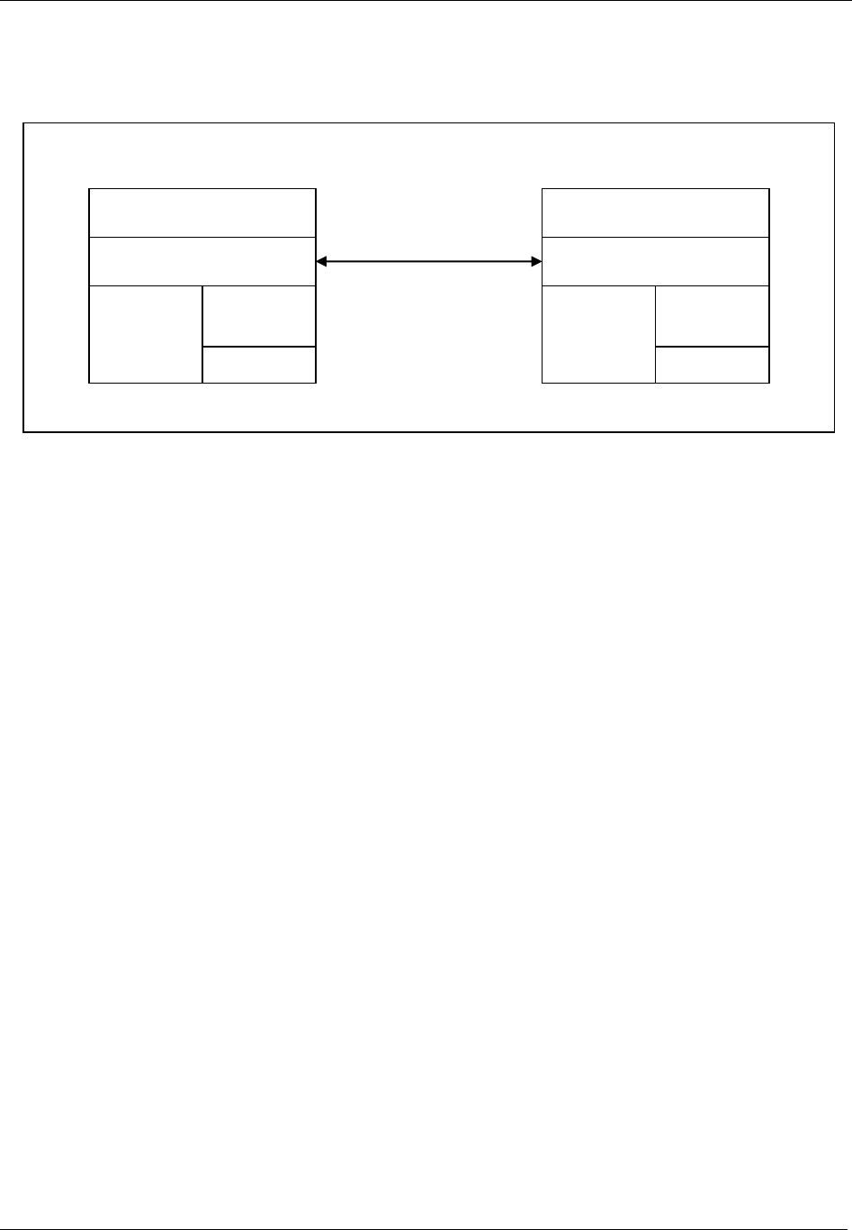
Message categories
21 (285)
2 Using Open Protocol
This section describes the communication structure between the integrator HW and the controller.
Figure 2 Communication structure
2.1 Communication
The Open Protocol can be run using Ethernet or serial communication. The Open Protocol is a full duplex
protocol, which means that data can be sent and received at the same time. Every communication partner
must be able to operate a send and receive facility simultaneously.
How support of Ethernet or/and serial communication is available or not is described in the controller
specific implementation document.
2.1.1 Ethernet protocol
The integrator connects to the controller, and the controller accepts the connection. The controller is the
server, and the integrator application is the client. The protocol used is TCP/IP. The default port used for
the communication is 4545.
Note! Ensure that the port is correctly configured in the controller!
TCP/IP
Open Protocol
Integrator Application
Integrator HW
Siemens
3964R
RS232
TCP/IP
Open Protocol
Controller
Siemens
3964R
RS232
Communication
Control data collection

Message categories
22 (285)
2.1.2 Serial protocol
There are two kinds of serial protocol.
Serial ASCII protocol
Serial ASCII protocol with 3964R handshake
Note! Ensure that the serial port is correctly configured according to the corresponding serial
protocol used!
When running serial communication, the messages are encapsulated according to the protocol used. The
messages within the encapsulation are the same regardless of type of communication.
Figure 3 Serial communication protocol, and Figure 5 Controller sending serial communication protocol
with 3964R handshake, show the encapsulation requirements that must be fulfilled when using serial
communication.
2.1.2.1 Serial ASCII protocol
All messages sent from the integrator to
the controller must be stamped with a 4
ASCII character tag before the STX
character: BEL (ASCII 0x07 bell) HT
(ASCII 0x09 horizontal tab) BEL (ASCII
0x07) HT (ASCII 0x09).
All messages must be encapsulated
between STX (ASCII 0x02 Start of Text)
and ETX (ASCII 0x03 End of Text).
Figure 3 Serial communication protocol
2.1.2.2 Serial ASCII protocol with 3964 R handshake
All messages exchanged between the controller and the integrator are transferred within the message
frame in accordance with Siemens Procedure 3964R.
The Procedure 3964R is a transfer protocol between two systems A and B. Every time one of the systems
wants to send, the following procedure is initiated.
request from A to B for data interchange
data interchange
end of data interchange
The protocol 3964R allows reliable data as the receiver must first signal to the transmitter that it is ready
to receive (communication setup) and then after data interchange must acknowledge correct reception.
Data integrity is ensured by an additional block check character (BCC).
Tightening controller
Integrator
STX<Message>ETX
BELHTBELHTSTX<Message>ETX
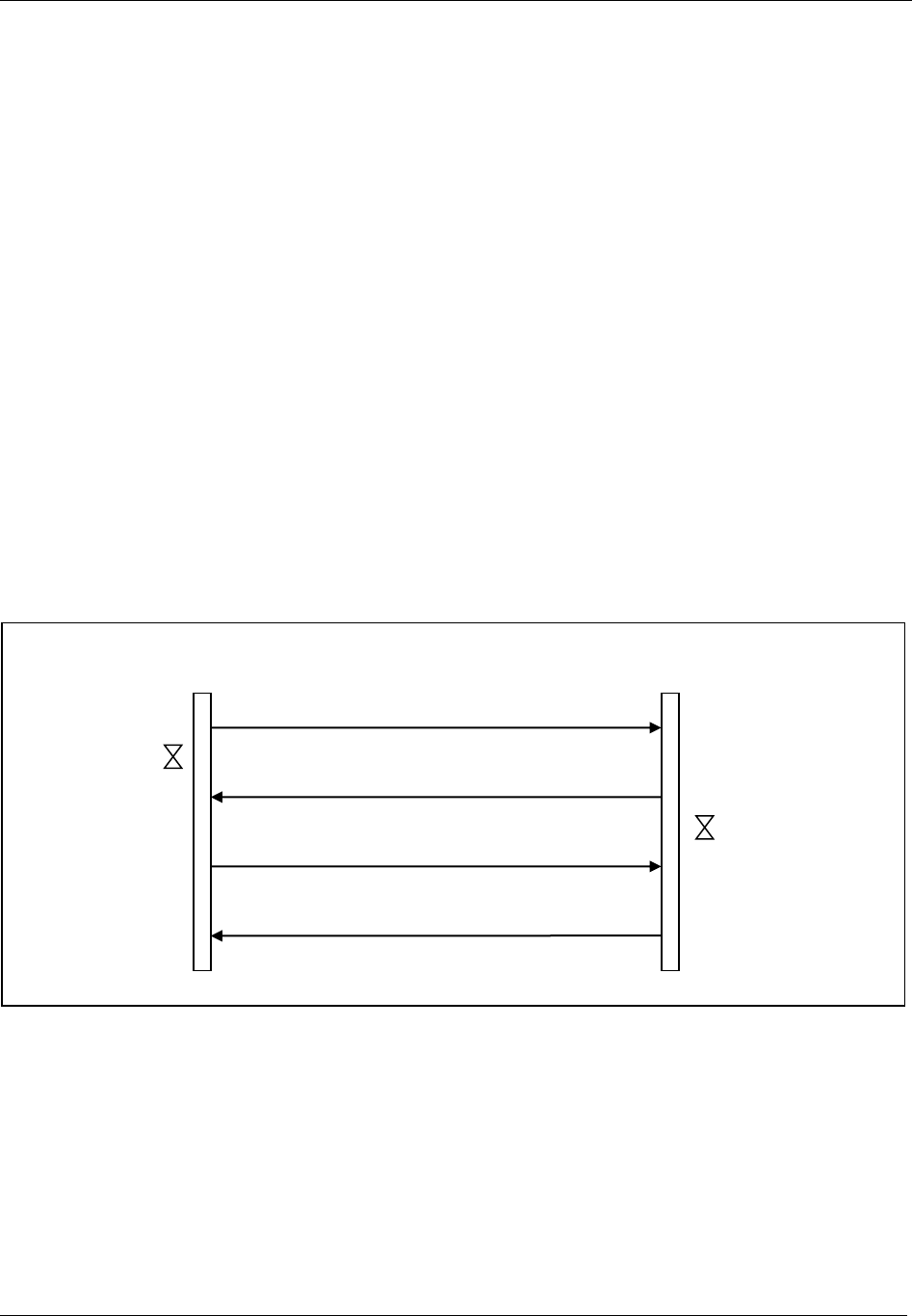
Message categories
23 (285)
The block check control is the XOR sum of all the transmitted data bytes. The generation begins with the
first byte of the message and ends after characters DLE (ASCII 0x10 Data Link Escape) and ETX (ASCII
0x03 End of Text).
The description is valid for both cases, when the integrator is the sender and the controller the receiver,
and the opposite. See Figure 4 and Figure 5 Controller sending serial communication protocol with 3964R
handshake.
Figure 4 Integrator sending serial communication protocol with 3964R handshake
Figure 5 Controller sending serial communication protocol with 3964R handshake
The following steps are included when the controller is sending to the integrator.
The controller sends the control character STX (ASCII 0x02 start of text) and waits for an
acknowledgment for 2s (acknowledgment timeout = 2s).
The integrator responds with the acknowledge character DLE (ASCII 0x10 data link escape) and the
Controller reverts to transmit mode.
If the integrator responds with control character NAK (ASCII 0x15 Negative acknowledgment) or any
other control character (apart from DLE) or if the acknowledgment delay time elapses, the connection
STX
Tightening controller
Integrator
Acknowledge-
ment timeout
2s
DLE
DLE
STX<Message>ETXDLEETXBCC
Character delay
timeout 100 ms

Message categories
24 (285)
setup procedure has failed. The connection setup procedure is aborted after a total of 6 unsuccessful
attempts.
The Controller sends an Open Protocol serial message followed by the characters ETX, DLE, ETX and
BCC as end identifier. The controller then waits for an acknowledgement character from the integrator.
The integrator monitors the incoming time between two characters. The interval between two characters
may not exceed the character delay timeout =100 ms.
The integrator sends the control character DLE and the Open Protocol message has been accepted error
free.
If the integrator responds with control character NAK (ASCII 0x15 Negative acknowledgment) or any
other character (apart from DLE) or if the acknowledgment delay time elapses with no answer, then the
transmission is aborted and the controller starts a new connection setup with character STX. The
procedure is aborted and the controller sends a NAK to the integrator after a total of six unsuccessful
attempts.
The following is also applicable:
If the integrator sends a NAK during transmission, then the controller aborts the transmission and repeats
it in the manner described above. In the case of any other character the integrator waits for the character
delay time to elapse and then sends a NAK.
If the integrator receives an STX from the controller in idle state, it answers with DLE. If it receives any
other character than STX in idle state it waits for the character delay time to elapse and then sends a NAK.
After each character, the next character is awaited during the character delay time =100ms. If the character
delay time elapses without new reception a NAK is sent to the controller.
If the integrator detects the character string DLE ETX BCC, it terminates reception. It then compares the
BCC with the internally generated one. If the BCC is correct and no error reception has occurred it sends a
DLE to the controller. If the BCC is not correct a NAK is sent to the controller. A retry is then awaited. If
it is not possible to receive the message with error free BCC after 6 attempts, the integrator aborts the
reception.

Message categories
25 (285)
2.2 Message structure
Most of the information sent over the communication links is in ASCII format. Some messages can also
contain binary data and this is described at each MID.
A message consists of three parts; header, data field and message end. The sections below describe each
part in detail.
2.2.1.1 Example
This following example shows MID 0071 Alarm.
Figure 6 shows the number of the byte above the message.
Figure 7 shows the same message without the numbers but with the spaces shown.
The spaces must be included according to each message structure.
1
2
3
4
5
6
7
8
9
10
11
12
13
14
15
16
17
18
19
20
21
22
23
24
25
26
27
28
29
30
31
32
33
34
35
36
37
38
39
40
41
42
43
44
45
46
47
48
49
50
51
52
53
54
0
0
5
3
0
0
7
1
0
1
E
4
0
4
0
2
1
0
3
1
0
4
2
0
0
8
-
0
9
-
2
5
:
1
0
:
1
4
:
1
6
N
U
L
Figure 6 Message example with byte number
Figure 7 Message example without byte number
00530071 01E404021031042008-09-25:10:14:16NUL

Message categories
26 (285)
2.2.2 Header
The header contains 20 bytes according to Table 1.
Table 1 Header content
Message part
Byte
Parameter
Value
Header
1-4
Length
The length is the length of the header plus the data field
excluding the NUL termination.
The header always includes information about the length
of the message. The length is represented by four ASCII
digits (‘0’…’9’) specifying a range of 0000 to 9999.
When using the message linking functionality the length
represents the length of each message part number.
When having one ASCII part followed by an binary part
the length is the total length of the message.
5-8
MID
The MID is four bytes long and is specified by four ASCII
digits (‘0’…’9’). The MID describes how to interpret the
message.
9-11
Revision
The revision of the MID is specified by three ASCII digits
(‘0’…’9’).
The MID Revision is unique per MID and is used in case
different versions are available for the same MID. Using
the revision number the integrator can subscribe or ask
for different versions of the same MID. By default the
MID revision number is three spaces long.
If the initial MID Revision (revision 1) is required there is
three different ways to get it, either send three spaces or
000 or 001.
12
No ack flag
ONLY FOR SUBSCRIPTION MIDs.
The No Ack Flag is used when setting a subscription. If
the No Ack flag is not set in a subscription it means that
the subscriber will acknowledge each “push” message
sent by the controller (reliable mode).
If set, the controller will only push out the information
required without waiting for a receive acknowledgement
from the subscriber (unreliable mode).
Note! NOT USED WHEN USING SEQUENCE NUMBER
HANDLING
13-14
Station ID
The station the message is addressed to in the case of
controller with multi-station configuration. The station ID
is 2 byte long and is specified by two ASCII digits
(‘0’…’9’). Two spaces are considered as station 1
(default value).
15-16
Spindle ID
The spindle the message is addressed to in the case
several spindles are connected to the same controller.
The spindle ID is 2 bytes long and is specified by two
ASCII digits (‘0’…’9’). Two spaces are considered as
spindle 1 (default value).

Message categories
27 (285)
17-18
Sequence number
From OP Spec. 2.0. 1-99-1. For acknowledging on “Link
Level” with MIDs 0997 and 0998.
Not used if space or zero and not 1-99.
At communication restart MID 0001/MID 0002 it must be
set to one and info in MID 0002 is telling if possible to
use or not. It is backward compatible and If used it will
substitute the No Ack flag and all special subscription
data messages ACK MIDs.
19
Number of message
parts
From OP spec. 2.0. Linking function can be up to 9 =
possible to send 9*9999 bytes messages. ~ 90 kB.
Used when the message length is overflowing the max
length of 9999.Not used if space or zero.
20
Message part number
From OP spec. 2.0. Linking function, can be 1- 9 at
message length > 9999.
Not used if space or zero
Data field
21
21-Length
See revisions or data patterns for variable data fields
Message end
See Value column
At whole message in ASCII the end = NULL
OP Spec. 2.0
At first part of message in ASCII and followed by an
binary part, the ASCII part is ended with a NULL
character just before the first data of the binary part
begins.
The Length and MID are padded on the left with zeroes (ASCII 0x30).
2.2.3 New MID numbers use from OP 2.0
All new MIDs creation has to use the MID numbers groups as defined below. It is divided into data
type/function type groups. This is the rule from OP spec. version 2.0 and upwards.
These are the existing groups of MID number series:
Job message MID 600-699
Tool messages MID 700-799
VIN Messages MID 800-899
Tightening result messages MID 900-999
Alarm messages MID 1000-1099
Time messages MID 1100-1199
Multi-spindle status messages MID 1200-1299
Multi-spindle result messages MID 1300-1399
User interface messages MID 1400-1499
Job messages, advanced MID 1500-1599

Message categories
28 (285)
Multiple identifiers messages MID 1600-1699
I/O Interface MID 1700-1799
PLC user data messages MID 1800-1899
Selector messages MID 1900-1999
Tool Location System messages MID 2000-2099
Controller messages MID 2100-2199
Statistic messages MID 2200-2299
Automatic/Manual mode messages MID 2300-2399
Open Protocol Commands Disabled MID 2400-2499
Parameter Set Messages MID 2500-2599
New groups from MID 2600.
A new MID is hence needed to be specified when a new data type is wanted to be transferred, either in an
existing group or within a new group.
2.2.4 MID with both ASCII and binary data from OP 2.0
MID’s with binary data has one ASCII data part and one binary data part. The ASCII part is always sent
first together with the header and is ended with an NUL character. Thereafter the binary data begins and
no NUL character is sent after the binary data.
The Header length is always the TOTAL length of the message , i.e. the length of the ASCII data
including the header, the NUL character and all the binary data.
These are the MID’s that has binary data in the message
Table 2 Message with binary data contents
MID
Name
Description
0900
MID 0900 Trace curve data message
All Trace sample is sent in binary format
2.2.5 Sequence number functionality from OP spec. 2.0
The sequence number is used in conjunction with MID 0006 and MID 0007 for communication
acknowledging on Application Link Level. The sequence number is set to 1-99-1 etc.
The sequence number is to be used if the fields are set difference from space or zero and is set to 1-
99.
At communication restart with MID 0001/MID 0002 exchange, the sequence number must be initialized
to 01 as the first sequence number to use for data transmission and the first sequence number to expect at
first data message receiving.
In the MID 0002 information is if it is possible to use it or not. See description on MID 0002.

Message categories
29 (285)
If used, it will override the No Ack flag and all special subscription data messages ACK MIDs that
shall not be used.
The benefits of using sequence numbering and MID 0006 and MID 0007 acknowledging is that a much
faster acknowledge of received message can be achieved without application level performance
dependency/delays for communication acknowledge.
Furthermore it is possible to recognize retransmissions, avoiding to load the controller with commands,
requests or subscriptions that has already been taken care of but not yet been fully performed and
acknowledged by the application level with MID 0004, MID 0005 or the direct Request Reply Data.
Using Sequence number functionality means that all messages (Requests, Commands or Subscriptions)
will be fast acknowledged on an Application Link Level (MID 0007) which also means that the message
has been formally checked and correct received.
If not formally correct, the message will be acknowledged with MID 0006 and an error code that tells the
receiver about the reason.
If correct received the wanted controller action will be performed on the Application Level and will later
result in either a successful action done through MID 0005 message or a direct Request Reply Data
message response.
At an unsuccessful action, the response will be an MID 0004 message.
In this case the MID 0004 and MID 0005 shall not be seen upon as acknowledgements anymore but as
messages that also shall be acknowledged by MID 0006 or MID 0007.

Message categories
30 (285)
2.2.6 Message linking functionality from OP spec 2.0
Message linking functionality is used when the message length are more than 9999 bytes. Another reason
could be that the equipment using Open Protocol has a reduced possibility to have huge buffers but
anyway wants to have the possibly to send huge messages.
A linked message is a message divided into a number of transmissions, where each transmission consists
of the Header and a part of the whole message data field.
The break points for next part of the message to be put into a part’s data field must be aligned with a
parameter data field size.
Next part of a message data field always starts at byte 21 after the header.
Number of Message parts” field can be up to 9 and are used if different from space. Valid values are 1-9.
This gives the possibility to send 9*9999 bytes messages. ~ 90 kB
2.3 Static Data Field use
The Static Data Field is ASCII data, representing the data. The data contains a list of parameters
depending on the MID. Each parameter is represented with an ID and the parameter value. Note that the
ID always is 2 bytes. The data field can be empty or contain a maximum of 9979 bytes.
Table 3 Data field content
Message part
Byte
Parameter
Value
Data field
21-22
01
Parameter ID (00...99), length two bytes. The parameter
ID is padded on the left with the ASCII characters ‘0’.
23 -
Parameter 01 value
Parameter value is defined by parameter selection (fixed
number of bytes).
ASCII digits (‘0’…’9’) or ASCII characters between 0x20
and 0x7F Hex.
If the Parameter value is specified only by ASCII digits,
then the parameter value is padded on the left with the
ASCII characters ‘0’.
If the Parameter value is specified by ASCII characters,
then the parameter value is padded on the right with
space <SPC> (ASCII character 0x20 Hex).
If the Parameter value is not supported, the whole
parameter field is filled with spaces <SPC> (ASCII
character 0x20 Hex).
n-
02
Parameter 02
n+2-
Parameter 02 value
Parameter 02 value…
03
Parameter 03
Parameter 02 value
Parameter 03 value…

Message categories
31 (285)
2.3.1 Static Data field implementation rules
All the parameters of the data field must be sent.
The data field of each message is subject to future modifications handled by adding MID revisions. A new
revision can include new parameters or increased length of the data field.
At implementation of an existing MID with a number of versions all versions must be supported
If the not supported parameters can be determined as never to be supported when trying to use an existing
MID, instead a new MID MUST be defined with these parameters excluded, which in the long run will
give a cleaner interface. To be sent to the Open Protocol committee.
All torque and angle values sent in the data part are sent in units Nm and degrees when nothing else is
specified. For degrees one turn represents 360 degrees.

Message categories
32 (285)
2.4 Variable data field use from OP spec 2.0
Variable data field is a possibility to use a full variable way to send data.
This pattern is substituting all use of the static field implementation rules and revision handling.
The data represented in a variable field pattern can be placed anywhere in the message after the header or
not sent at all. Which data that should be sent is a configuration issue in each product.
The Unit Names and Data Type names are defined in product independent global namespaces. New names
can be defined in later releases of this document.
For Unit Names, Parameter IDs and Data Types, see chapter 6.0.
In each MID description they are also described if used.
If used and the use of this pattern is described under each MID description.
Table 4 Variable Data field content
Parameter
Size
Data type
Description
Number of
data fields
3
UI
The number of variable data fields in the telegram. If no data fields exist “000” will
be sent. Must be the first of each section of variable data fields.
Data fields
Vary
This section is repeated Number of data fields times. If Number of data fields = 000,
this section is not sent.
Parameter
Size
[byte]
Data
type
Description
Parameter id
(PID).
5
UI
The available PID’s may vary depending on the
system type.
Length
3
UI
Length of data value.
Data Type
2
UI
Data type of the data value.
Unit
3
UI
Unit of the data.
Step no.
4
UI
The step number for the result variable. Sent as
0000 if not relevant
Data value
Length
The data value.
Note! All fields with strings are left adjusted and padded with spaces. All numerical fields are right
adjusted and padded with 0’s.

Message categories
33 (285)
2.4.1 Message End
The message end is empty.
Table 5 Message end content
Message part
Byte
Parameter
Value
Message end
1
Message end
If the message is pure ASCII the message is NUL
terminated. The NUL termination is not included in the
message length. In this manual this is illustrated with
NUL, ASCII 0x00.
From OP spec. 2.0 and forward:
If variable data field is used, there could be data fields
that are binary, then the length of data fields are to be
used as the message END determination.
Note! Before binary data is sent in a message there shall always be a NUL character.

Message categories
34 (285)
3 Implementation guidelines and
Communication
This chapter describes the contact establishment procedures and the basic messages that MUST be
implemented and handled.
It is also described how to use the messages in typical production situations.
3.1 Application Startup messages exchange
First message to send after connection is MID 0001 and expected MID 0002 as response if OK. If NOK
you will get MID 0004 as response with an error code.
3.2 Message acknowledging methods
There exists two different acknowledging methods to use by using the header in two different ways, see
Chapter 2.2.1. They are named as “Application Level acknowledging” and “Link Level acknowledging”
methods. The integrator must choose one of these methods.
The protocol allows the implementer to do the implementation of the “Link Level acknowledging” in such
a way that it will be possible to choose to use either method on message level.
If implemented in such a way and the controller supports the sequence numbering and link level
acknowledging, the integrator can choose to NOT use the sequence numbering and link level
acknowledging for a certain message by setting the sequence number to zero.
In this case the integrator must wait on the application level response for Commands, Requests and
Subscriptions. If the startup was done with Rev 6 or higher the RESPONSES still will be sequence
numbered and will demand a Link level acknowledging and sequence numbering handling on the
Integrator side.
The same can be applicable in the direction of Controller->Integrator depending on the implementation on
the Integrator side.
If it is possible to have a mix of sequence numbered/not sequence numbered messages on message level or
not, is described in the reference documents for each controller, as this is implementation dependent.
Both methods are described below.
3.2.1 Application Level acknowledging method
In this method there are two MIDs used for acknowledging. The MID 0005 is the positive response and is
given on a successful Command or Subscription action.
For a Request the positive response is the requested data in itself.

Message categories
35 (285)
MID 0004 is the negative response with error codes and is given if the Request, Command or Subscription
action fails for some reason.
Only one outstanding/unacknowledged message at a time is allowed before next can be sent. In other
words, the implementation must wait for an MID 0004 or MID 0005 acknowledge or an direct REQUEST
REPLY DATA acknowledge, depending on which type of Request, Command or Subscription that was
sent, before next message can be sent.
In conjunction with this method, the No Acknowledge flag can be used for subscription data message
acknowledging from the integrator side.
At MID 0004 response it is impossible to go on with the next message in a sequence, see more info under
chapter “Production Message sequences”.
If no answer to the command is received before the response timeout, the integrator should re-send the
command up to three times. After three times, the connection is considered lost and a new connection
must be established.
The disadvantages with this method are that a dependency of the Application level performance will be
built in for communication acknowledging being very slow sometimes and it can also be a problem with
handling of retransmissions of commands already under treatment in the controller.

Message categories
36 (285)
3.2.2 Link Level acknowledging method from OP spec. 2.0
When using the header sequence numbering the MID 9998 and MID 9997 is used for fast acknowledging
and the implementation of Open Protocol consists then of an Application Link Layer and Application
Layer.
OBS! It is really recommended and almost a mandatory to use this method instead of Application
Method acknowledging due to a lot of customer reported problems during the years of OP existence,
which will be solved by this OBS!.
On the Application Link Layer the MID 9998 and 9997 is handled and only one
outstanding/unacknowledged message at a time is allowed.
The mid 0004 and MID 0005 messages are in this case to be handled as Application level messages and
be acknowledged as such by the MID 9998 or MID 9997 acknowledge messages.
All special acknowledge messages for the subscription data messages shall not be used.
At connection and communication restart with MID 0001/MID 0002 exchange, the sequence number must
be initialized to 01 as the first sequence number to use for data transmission and the first sequence number
to expect at first data message receiving.
The sequence number must hence be held and treated independently in each direction of the Integrator-
Controller communication and is wrapped around through 1-99-1.
Data message acknowledge with MID 9998 or MID 9997 shall be done as soon as the header and length
check is OK with the sequence number received + 1. The new sequence number will then be the next
expected in the next data message.
If the header check fails, the data message shall be acknowledged with MID 9998 with the sequence
number received + 1 and an error code that specifies the type of error.
If an already acknowledged data message is received with the same sequence number again, it is a
retransmission and shall be acknowledged with the same acknowledge as last time, but no action shall be
taken for application level treatment.
If a data message sequence number is not an retransmission and neither the next expected, the
acknowledge shall be the MID 9998 with an error code and the sequence number set to next expected,
telling the sending part what the next expected sequence number is. The proper action to take in this
situation is to do a session disconnection/reconnection for synchronizing.
If no MID 9998 or MID 9997 acknowledge is received on a sent data message within a certain the time
out time, the data message shall be retransmitted up to three times. If no acknowledge has been received
after that, the connection is taken down and a try for a new one shall be done, whereby the sequence
numbering is started up from the beginning again.
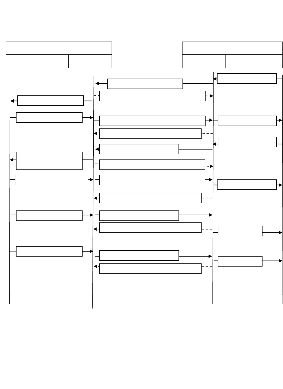
Message categories
37 (285)
Communication example: Normal communication
Figure 8 Normal communication
Controller
Application layer
Link layer
Integrator
Link layer
Application layer
MID 0060 seq. 01
MID 9997 seq. 03 next exp seq at Controller= 03
Result subscription request
Result subscription accept
Pset selected subscription
request
Pset selected subscription accept
Pset selected
Pset selected
Result Subscription accept
Pset selected subscription
request
Pset selected subscr accept
Last result
MID 0061 seq. 04
Last result
Result subscription request
MID 9997 seq. 02 next exp seq at Controller= 02
MID 0005 Result Subscription accept seq. 01
MID 9997 seq. 02 next exp seq at Integrator = 02
MID 0014 seq. 02
MID 0005 Pset selected Subscription accept seq. 02
MID 9997 seq. 03 next exp seq at Integrator = 03
MID 0015 seq. 03
MID 9997 seq. 04 next exp seq at Integrator = 04
MID 9997 seq. 05 next exp seq at Integrator = 05
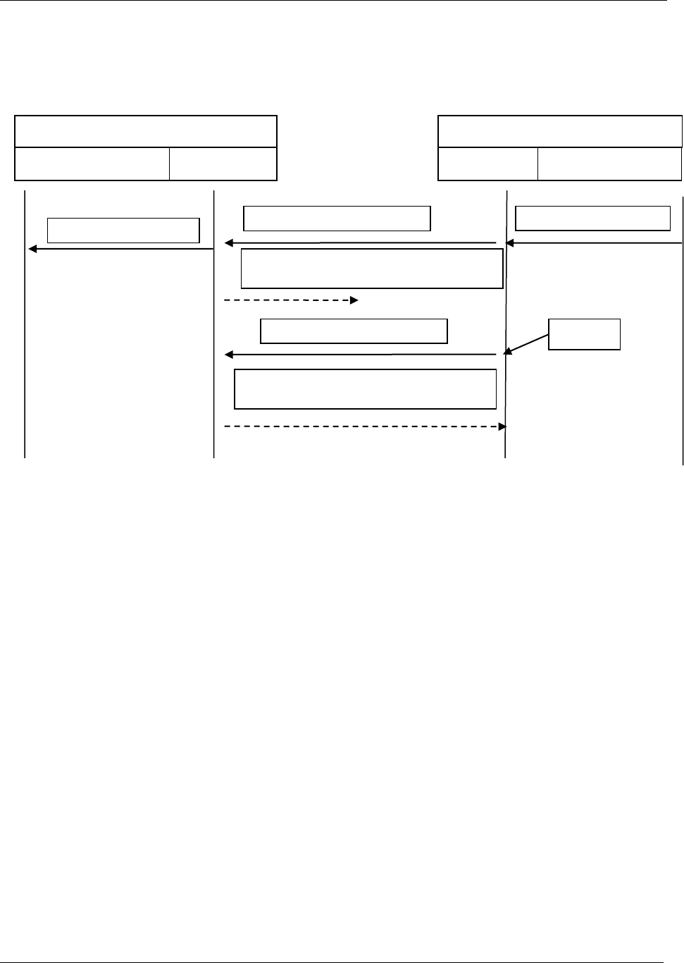
Message categories
38 (285)
Communication example with error: No Ack received
Figure 9 No Acknowledge received
Controller
Application layer
Link layer
Integrator
Link layer
Application layer
MID 0060 seq. 01
MID 9997 seq. 02 next exp seq at Controller= 02
No action on Application layer!!!
Result subscription request
Result subscription request
MID 0060 seq. 01 Retransmission
MID 9997 seq. 02 next exp seq at Controller= 02
Broken
Time Out
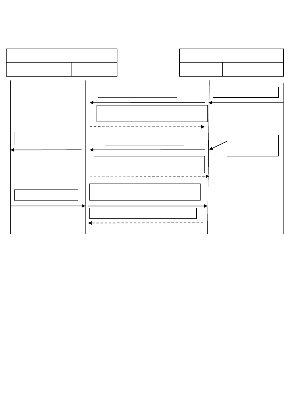
Message categories
39 (285)
Communication error: Wrong sequence number
Figure 10 Wrong sequence numbering
Controller
Application layer
Link layer
Integrator
Link layer
Application layer
MID 0060 seq. 02 = Wrong seq.nr.
MID 9997 seq. 02 next exp seq at Controller= 02
Result subscription request
Result subscription request
MID 0060 seq. 01 Retransmission
MID 9998 seq. 01 next exp seq at Controller= 01
Code = 0003
No Time Out. Direct
retransmission on
MID 0006
MID 0005 seq. 01Subscription accept
MID 9997 seq. 02 next exp seq at Integrator = 02
Result subscription accept
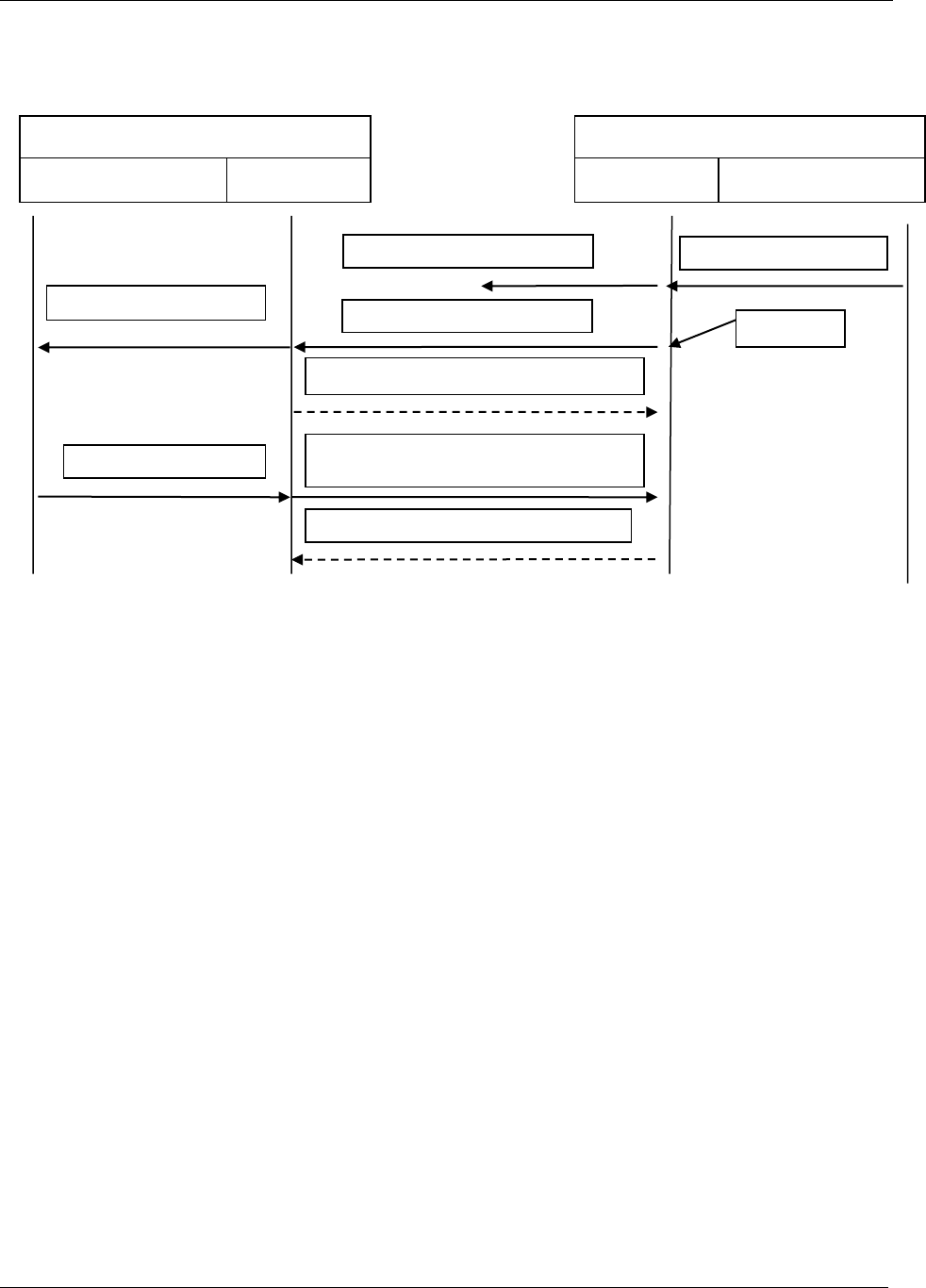
Message categories
40 (285)
Communication error: Transmission of data message broken
Figure 11 Transmission broken
Controller
Application layer
Link layer
Integrator
Link layer
Application layer
MID 0060 seq. 01 . broken
MID 0005 seq. 01Subscription accept
Result subscription request
Result subscription request
MID 0060 seq. 01 Retransmission
MID 9997 seq. 02 next exp seq at Controller= 02
Time Out.
MID 9997 seq. 02 next exp seq at Integrator =
02
Result subscription accept
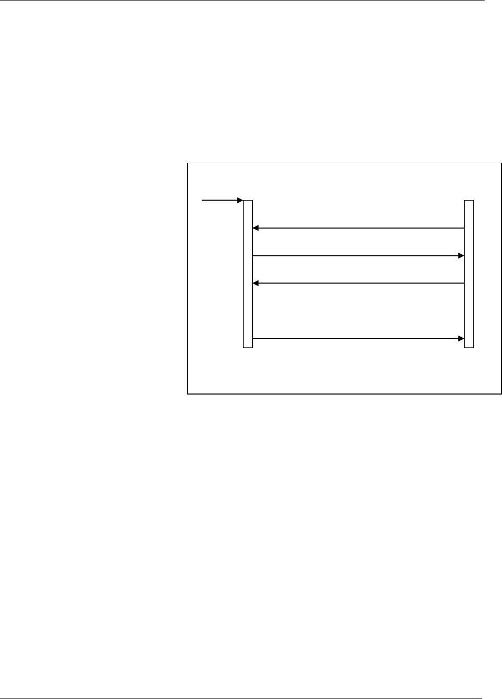
Message categories
41 (285)
3.3 Establishing contact
This section describes how to set up a communication.
3.3.1 Ethernet connection
Prerequisite: The controller has an IP address and listens to port 4545.
1. The controller listens to port
4545 acting as a server.
Figure 12 Ethernet connection example
2. The integrator connects to the
controller acting as client.
3. The controller accepts the
connection.
4. The integrator sends MID 0001
Communication start.
5. The controller answers
MID 0002 Communication start
acknowledge with Cell ID 0001,
Channel ID 04 and Controller
name Airbag.
Tightening controller
Integrator
MID 0002
MID 0001
TCP/IP [SYN ACK] accept
Port
4545
TCP/IP [SYN] connect

Message categories
42 (285)
3.3.2 Serial connection
Prerequisite: The controller and the integrator are connected through a serial cable.
1. The integrator sends
MID 0001 Communication start.
Figure 13 Serial connection example
2. The controller answers
MID 0002 Communication start
acknowledge with Cell ID 0001,
Channel ID 04 and Controller
name Airbag.
Tightening controller
Integrator
STX
MID0002[NUL]
ETX
BELHTBELHTSTX
MID0001[NUL]
ETX

Message categories
43 (285)
3.3.3 Serial connection with 3964R
1. The integrator sends request
for connection with the
controller.
Figure 14 Serial connection with 3964R, example
2. The controller accepts the
request to send.
3. The integrator sends
MID 0001 Communication start.
4. The controller accepts the
communication.
5. The controller sends request to
send on Siemens protocol.
6. The integrator accepts the
communication.
7. The controller answers
MID 0002 Communication start
acknowledge with Cell ID 0001,
Channel ID 04 and Controller
name Airbag.
8. The integrator accepts the
message.
STX
Tightening controller
Integrator
DLE
DLE
BELHTBELHTSTX
MID0001
ETXBCC
STX
DLE
STX
MID0002
ETXDLEETXBCC
DLE

Message categories
44 (285)
3.3.4 Session control connections
In some controllers there is a possibility to do several Integrator side connections to the controller. These
connections has the categories of being Actor, Viewer or Classic.
These categories represents MID type’s categories rights to do.
From a connection of type Actor the Integrator has all rights to perform Subscriptions, Commands and
Requests and if connected will preventing the Commands rights for the Viewer connection.
The Viewer connection can still do Requests and Subscriptions.
If there are a number of Classic connections and the Integrator side do an Actor connection, then these
Classic connections should be transformed to Viewers.
As long as there are only Classic connections, all of them has all rights and the Integrator side must have
the responsibility to prevent that several connections can do Commands at the same time.
When using connection type Actor this should be handled in the Controller implementation.
The Controller implementation can for instance realize the session control by using different TCP ports for
the Actor different from the Viewer and Classic connections type.
The actual implementation is described in the Controller Open Protocol spec. documents.
Below is the overall Controller requirements for the session control functionality:
1. Connection on session for Actor shall do it impossible to do commands from other
connections.
2. At connection with session for Actor it still shall be possible to do subscriptions and data
requests (Upload) from all other connections transformed to Viewers.
3. At disconnection of Actor session the commands shall again be possible to do from
Classic Sessions (transformed from Viewer sessions).
4. The maximum of session connections overall should be limited.
5. Tries for more than the limited session connections shall result in the MID 0004 with
error code 16 “Connection rejected”.
6. Tries for commands on Classis/Viewer connections when an Actor connection exists shall
result in a MID 0004 with error code 92 = “Commands is disabled”.
7. Tries for another Actor connection shall result in MID 0004 with error code 35 “Other
Actor client already connected”

Message categories
45 (285)
3.4 Starting a subscription
The example shows the sequence for MID 0060 Last tightening data subscribe and MID 0061 Last tightening
data upload. These messages must be implemented to get results. Prerequisite: A communication session
is already established. The example shows only the data sent, not the protocol frames. Dotted lines are for
when using sequence numbering with MID 0006 and MID 0007 acknowledging. The figures don’t show
the different layers at sequenced numbering use.
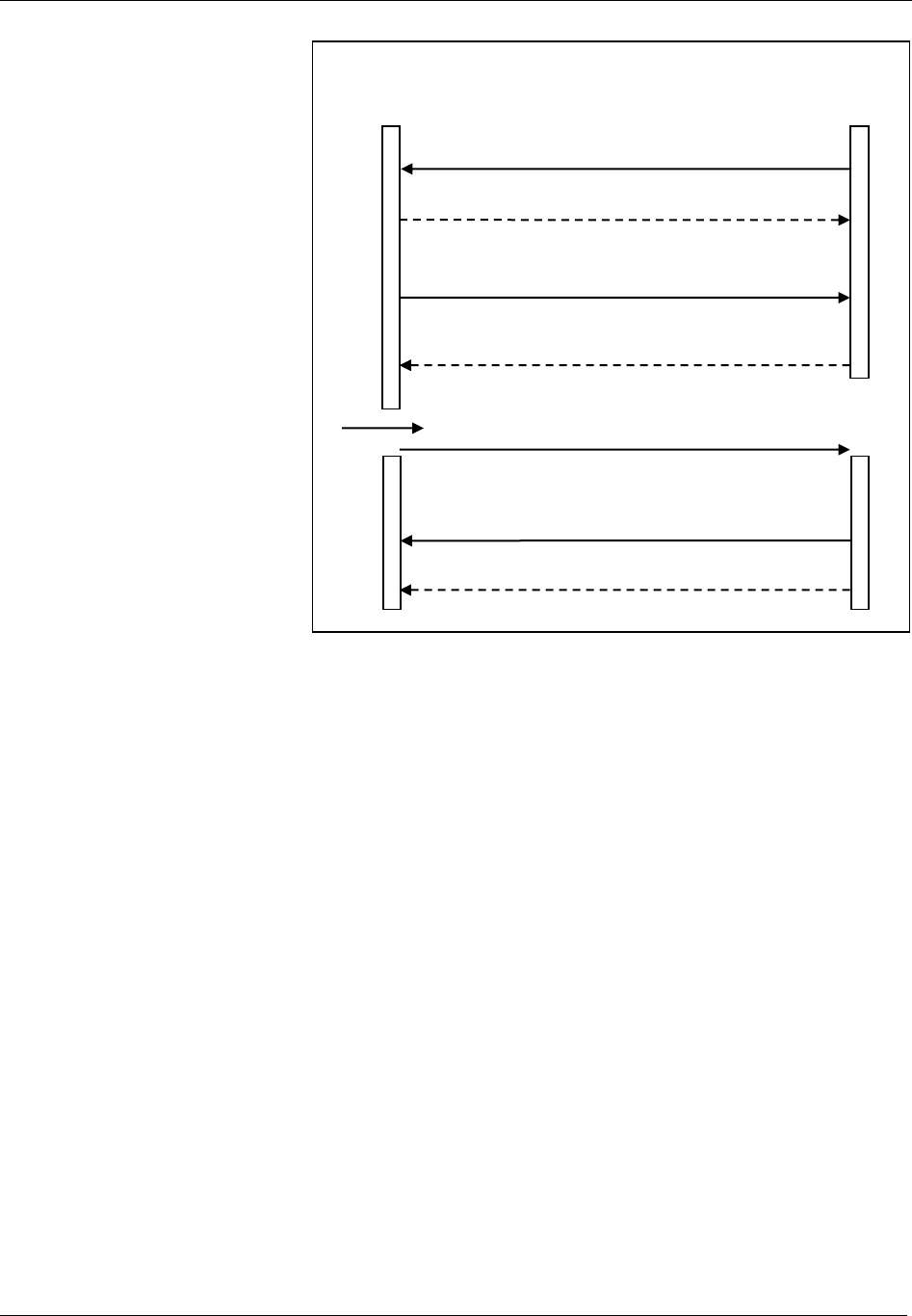
Message categories
46 (285)
1. The integrator sends
MID 0060 Last tightening result
data subscribe. The subscription
is for revision number 6.
Figure 15 Starting a subscription
2. The controller sends MID
9997 if sequence numbering is
used and MID 0005 Command
accepted (As application
message if sequence numbering
is used).
3. A tightening is performed.
(See arrow in figure.)
4. The controller sends
MID 0061 Last tightening result
data upload and then waits for
acknowledgement.
See description of MID 0061.
The integrator sends
MID 0062 Last tightening result
data acknowledge OR
MID9997when sequence
numbering is used.
Tightening controller
Integrator
MID 0060 Rev.6
seq 01
MID 0005
seq 01
MID 0061
seq 01
MID 0062
MID 9997
seq 02
MID 9997
seq 02
OR MID 9997
seq 02
Tightening done
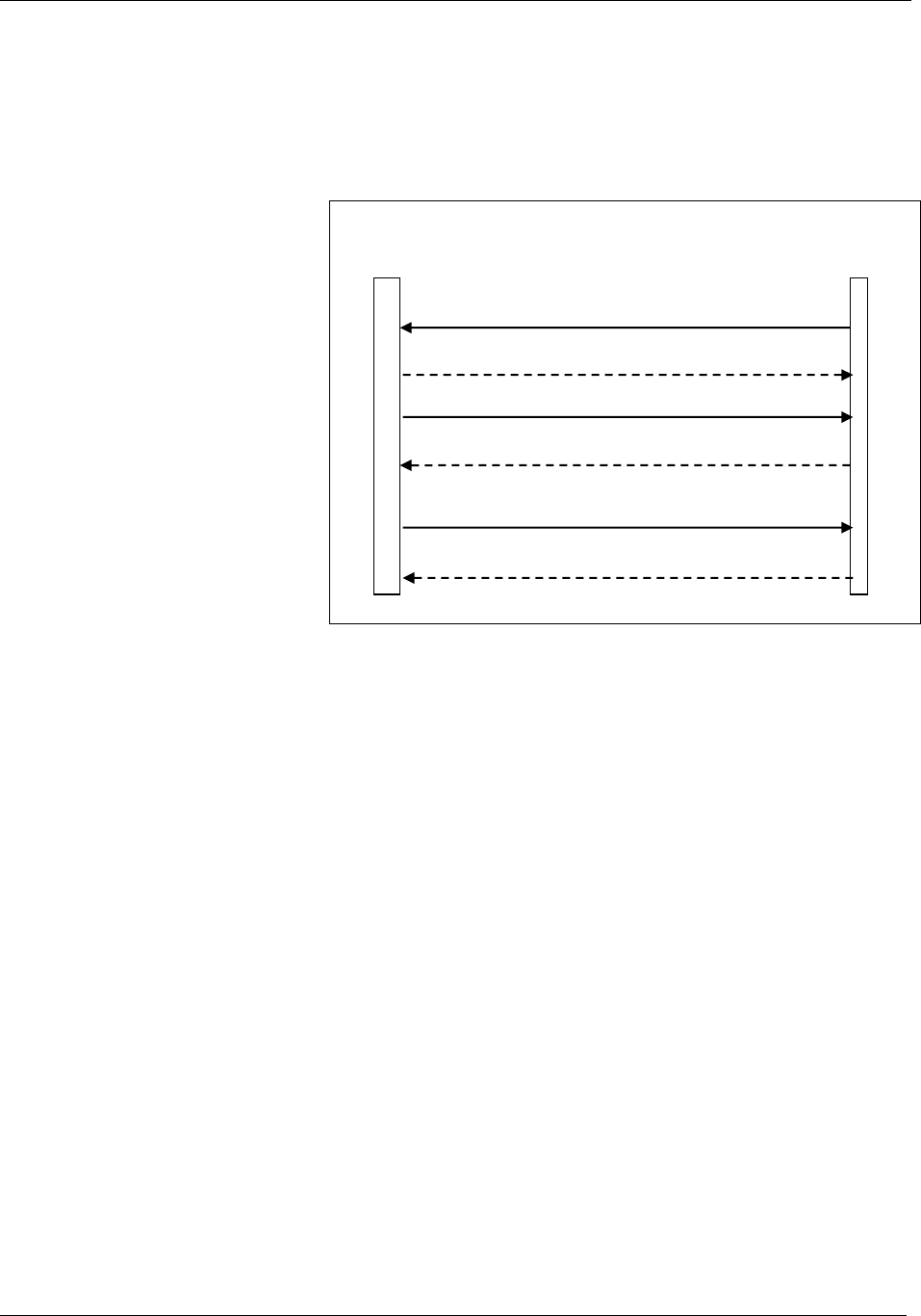
Message categories
47 (285)
3.5 Sending a request
This example shows a request for collecting parameter set data. Dotted lines are for when using sequence
numbering with MID 9998 and MID 9997 acknowledging.
1. The integrator sends
MID 0012 Parameter set data
upload request.
The request is sent for parameter
set number 001.
Figure 16 Sending a request
2. The controller sends MID 0013
Parameter set data upload reply if
OK. For a description of the
parameters, see MID 0013
description. If error, a response
of MID 0004 with error code is
sent from the Controller.
Tightening controller
Integrator
MID 0012 Pset ID = 1
seq 01
MID 0013
seq 01
OR MID 0004
seq 01
MID 9997
seq 02
MID 9997
seq 02
MID 9997
seq 02

Message categories
48 (285)
3.6 Sending a command
This example shows a command for setting primary tool. Dotted lines are for when using sequence
numbering with MID 9998 and MID 9997 acknowledging.
1. The integrator sends
MID 0041 Set Primary tool.
The request is sent for primary
tool = 1
Figure 17 Send a command
2. The controller sends MID 0005
if the command has been
performed. Otherwise the MID
0004 is sent with an error code.
Tightening controller
Integrator
MID 0041 Primary tool=1.
Seq 01
MID 0005
seq 01
MID 9997
seq 02
OR MID 0004
seq 01
MID 9997
seq 02
MID 9997
seq 02

Message categories
49 (285)
3.7 CCS ruled production message sequences
Examples of typical application level message sequences to use in a production.
3.7.1 General Job/Work order selection rules
Regardless of used Controller or CCS system all new selections for starting new tightening cycles SHALL
start with sending the Job Abortion/Result request command to the Controller. This is especially important
when wireless tools are connected to the Controller with a wireless link going down and up now and then
and when a current Job Work order is really interrupted by the CCS sending a Job abortion command. If
the CCS isn’t capable of executing a Job abortion/result request command, the PF will do it itself at Job
Work order receiving.
The functionality of the Job Abortion/Result request command implementation contains the following:
1. A cleanup of the controller and the tool from any possible remaining work and results in a possible
current selected Job.
2. Securing of that all results done from the current Job will be reported with proper and true build data
such as VIN number etc., if any, to the CCS, before executing the Job abortion and entering the new Work
order.
3. The CCS has to wait for an MID 0005 acknowledge and optionally Job Info message with Job aborted
status, before issuing any of the Work order commands if the Job abortion command is used.
4. In the meantime the Controller goes into a “Job abortion in progress” state since it can take some time
to perform the Job abortion clean up.
5. For wireless tools it is included in the Job abortion clean up implementation, to check up whether the
tool has any remaining results not reported yet by asking the tool, and see to, that these results will be
received by the CCS PF interface and if possible be reported to the CCS before the actual Job abortion
command is executed.
NOTE: The reporting of such results should be parameterized to be sent, YES or NO.
6. At tool going inaccessible during the Job abortion/result request process, it will take more time to report
the possible remaining results and this will not be finished before the tool goes accessible again and after
results reporting. In this case the CCS PF interface will acknowledge the Work order with MID 0004 and
error code for “Tool inaccessible”.
NOTE: The behavior of this is recommended to be parameterized like: “Job abortion after all remaining
results reported” or ” Job abortion if the tool is or goes inaccessible during the result request process” or
”Unconditional Job abortion”. At the two last alternatives it is recommended to store the results as “latent”
marked in the controller’s database and also use the Toolsnet.
7. At tool accessible during the process of Job abortion/Result request the Work order command will be
acknowledged with MID 0005 when the Job has been aborted and/or all possible remaining results has
been received by the CCS Interface and if possible reported to the CCS.

Message categories
50 (285)
8. New commands for Work order from the CCS, during the time for Job abortion in progress and
transferring of possible remaining results, are acknowledged with MID 0004 with error code for “Job
abortion in progress”. It is the CCS responsibility to has knowledge of rejected Work orders.
9. New commands for Work order in the state of “Tool inaccessible” is acknowledged with MID 0004
with error code for “Tool inaccessible” if parameterized to “Job abortion after all remaining results
reported”.
The Job abortion/Result request process is valid for the following methods of selecting a new Work order
from the CCS:
1. VIN number selection of Pset, Multistage or Job if so configured in the controller, MID 0050 or
MID 0152.
2. Job selection command, MID 0038
3. Job selection through Executing Dynamic Job command, MID 0140
4. Pset or Multistage selection command, Dynamic Job embedded MID 2504
Also the following commands related to a Work order selection are acknowledge with MID 0004 with
error codes as above during the circumstances of “Job abortion in progress” or “Tool inaccessible” and
parameterized to “Job abortion after all remaining results reported”:
1. Disable tool, MID 0042
2. Enable tool, MID 0043
3. Vin number, MID 0050
4. Set Pset Batch, MID 0019
5. Reset Pset Batch, MID 0020
6. Restart Job, MID 0039
7. Job Batch increment, MID 0128
8. Job Batch decrement, MID 0129
9. Multi Identifiers MID 0152
Communication sequences Example:
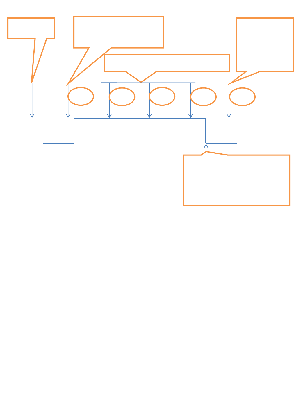
Message categories
51 (285)
Figure 19 Work Order example at parameterized to “Job abortion after all remaining results reported”
3.7.2 Production Control by Pset selection and tightening
After start up sequence the integrator should send the following messages once:
Request for Pset ID:s. MID 0010 and MID 0011 handling.
Subscription on Pset selected. MID 0014 – MID 0017 handling
Subscription on VIN number set according to MID 0050 – MID 0054 or MID 0150 – MID 0157 handling
Subscription on locked at batch done. MID 0021-MID 0024 handling. Parameter in PF set (P152 for PF
4000).
Subscription on Last tightening results. MID 0060-MID 0063 handling.
Subscription on selectable digital inputs as ex. Tool Running/Not Running. MID 0210 and MID 0211
handling
Set primary tool request (Optional. Could already been set in PF). MID 0046
At wireless tools use the Pairing Handling (Optional. Could already been done PF locally). MID 0047 and
MID 0048.
New Work Order 2
Tool goes inaccessible.
MID 0004 with error code
Work order
1
Subsequent Work Orders not performed
Tool goes accessible
All possible results from work
order 1 will be reported, if not
reported before, before any new
work order can be executed
3
4
5
6
2
Work Order 6
OK execution

Message categories
52 (285)
After that, the production can start with use of the following messages:
Command Abort Job. MID 0127.
Command Select Pset MID 0018.
Command Set VIN. MID 0050 or MID 0150 handling
Command Disable Tool. MID 0042.
Command Enable Tool. MID 0043.

Message categories
53 (285)
3.7.2.1 Sequence at production start up
Figure 18 Production startup Pset selection
Important: If at any of the above stages an MID 0004 is received, the intended production can not
be started. The integrator side must wait on the MID 0005.
Tightening controller
Integrator
MID 0010 Pset ID request
MID 0011 pset IDs
MID 0014 Subscr.on Pset selected.NoAck not set
MID 0021 Subscr.on Tool Locked at batch done. NoAck not set
MID 0060 Subscr.on Last tightening result. NoAck not set
MID 0051 or 00151 Subscr. For set VIN number. NoAck not set
MID 0046 Set primary Tool (Optional)
MID 0047 Tool pairing (Optional)
MID 0210 Subscr. on External monitored digin. NoAck not set

Message categories
54 (285)
3.7.2.2 Sequences at running production
Figure 19 Running production at Pset selection
Important: If at any of the above stages an MID 0004 is received, the intended production cannot be
started. The integrator side must wait on the MID 0005.
Integrator
MID 0042 Disable tool command. Integrator wait on acknowledge.
Ack.MID 0005 OR MID 0004.
MID 0018 Pset select. Integrator wait on MID 0015.
MID 0015 Selected Pset with Integrator Ack MID 0016.
MID 50 or MID 150 Set VIN number. Integrator Wait on MID 52 or MID 152
MID 0061 Last tightening result with Integrator Ack MID 0062
MID 0211 Tool not running with integrator ack MID 212. If subscribed
MID 0042 Disable tool command
MID 0211 Tool running with integrator ack MID 212. If subscribed
End of tightening sequence. Start a new one
Tightening controller
MID 0052 or 00152 Vin number with Integrator Ack MID 0053 or MID 0153
MID 0043 Enable tool. Integrator Wait on Last tightening result MID 0061
MID 0211 Tool not running with integrator ack MID 212. If subscribed
MID 0127 Abort Job. Integrator Wait on 0005
Ack MID 0005

Message categories
55 (285)
3.7.3 Production control by Job selection and tightening
PF locally configuration used with a number of Jobs configured below the summary of used messages.
After start up sequence the integrator should send the following messages ones:
Request for Job ID:s. MID 0030 and MID 0031 handling.
Subscription on Job Info. MID 0034 – MID 0037 handling.
Subscription on VIN number set according to MID 0050 – MID 0054 or MID 0150 – MID 0157 handling.
Use Job Info status. Or use Lock at Job done Parameter in PF set (J 302 for PF 4000).
Subscription on Last tightening results. MID 0060 – MID 0063 handling.
Suscription on selectable digins as ex. Tool Running/Not Running. MID 0210 and MID 0211 handling.
Set primary tool request (Optional. Could already been set in PF). MID 0046.
At wireless tools use the Pairing Handling (Optional. Could already been done PF locally). MID 0047 and
MID 0048.
After that, the production can start with use of the following commands:
Command Abort Job. MID 0127.
Command Select Job MID 0038
Command Set VIN. MID 0050 or MID 0150 handling
Command Disable Tool. MID 0042.
Command Enable Tool. MID 0043.

Message categories
56 (285)
3.7.3.1 Sequence at production start up
Figure 20 Production startup at Job selection
Important: If at any of the above stages an MID 0004 is received, the intended production cannot be
started. The integrator side must wait on the MID 0005.
Tightening controller
Integrator
MID 0030 Job ID request
MID 0031 Job IDs
MID 0034 Subscr.on Job Info.NoAck not set
MID 0060 Subscr.on Last tightening result. NoAck not set
MID 0210 Subscr. on External monitored digin. NoAck not set
MID 0046 Set primary Tool (Optional)
MID 0047 Tool pairing (Optional)
MID 0051 or 00151 Subscr. For set VIN number. NoAck not set

Message categories
57 (285)
3.7.3.2 Sequences at running production
Figure 21 Running production at Job selection
Important: If at any of the above stages an MID 0004 is received, the intended production can not
be started. The integrator side must wait on the MID 0005.
Integrator
MID 0042 Disable tool command.
Ack.MID 0005 OR MID 0004. Then MID 0038 if MID 0005
MID 0035 Job Info Selected with Integrator Ack MID 0036.
MID 0061 Last tightening result with Integrator Ack MID 0062
MID 0211 Tool not running with integrator ack MID 212.
MID 0042 Disable tool command etc.
MID 0211 Tool running with integrator ack MID 212.
End of Job tightening sequences. Start a new Job
Tightening controller
MID 0035 Job Info with Integrator Ack MID 0036.
Following sequence of messages is repeated for each tightening
done in the Job the number of times according to the set Job
batch size
MID 0211 Tool not running. With integrator ack MID 212.
MID 0052 or 00152 Vin number.
MID 0005 Job abortion acknowledge.
MID 0038 Job select.
MID 0050 or 00150 Set Vin number.
MID 0127 Job abortion command.
MID 0043 Enable tool command.

Message categories
58 (285)
3.8 Message End determination methods
To determinate the end of the message the implementer must check the length (in the header) of message
not just the NUL character.
This is due to that it not just ASCII based data that is sent. For the variable data fields containing a lot of
data the data is sent in binary formats.
Before binary data is sent in a telegram there shall be a NUL character sent to simplify the interpretation
of the message.
3.9 Version 2.0 implementation description
To be FULLY compliant with version 2.0 of this protocol the following MID’s and functionality must be
implemented, both in the controller and integrator side.
On which level the controller side is living up to version 2.0 shall be described in ref.documents.
3.9.1 Startup
Startup with MID 0001 with at least Rev 6 or higher and receiving of MID0002 with revision 6 or higher.
3.9.2 Link level acknowledging
The link level message sequence numbering, acknowledging and retransmission method with MIDs 9997
and 9998 acknowledging messages.
Used for ALL subscription data messages it will substitute the following messages:
MIDs 0016, 0023, 0036, 0053, 0062, 0092, 0102, 0108, 0125, 0153, 0212, 0218, 0222, 0243, 0252, 0263,
0402, 0422, 0502, 1203, 2605 and 8002.
All together 22 MID messages.
Furthermore will it give retransmission detection possibility and full acknowledging control in both
directions for ALL MIDs.
3.9.3 Generic Application data request
Generic Application data request is done through MID 0006.
Used for ALL possible application data requests it substitutes the following current messages:
MIDs 0010, 0012, 0030, 0032, 0040, 0081, 0214, 0300, 0310 and 0360
All together 10 MID messages

Message categories
59 (285)
3.9.4 Generic Application data subscription
Generic Application data subscriptions is done through MID 0008 and 0009.
Used for ALL possible application data subscriptions they substitutes the following current messages:
MIDs 0014, 0017, 0021, 0024, 0034, 0037, 0051, 0054, 0060, 0063, 0070, 0073, 0090, 0093, 0100, 0103,
0105, 0109, 0120, 0126, 0151, 0154, 0210, 0213, 0216, 0219, 0220, 0223, 0241, 0244, 0250, 0253, 0261,
0264, 0400, 0403, 0420, 0423, 0500, and 0503
All together 39 MID messages.
3.9.5 Data field variable parameter pattern
MIDs can be sent in either variable parameter data fields’ pattern or in the static variable fields pattern as
described in Message Structure.
In version 2.0 the variable data field pattern was introduced, and the possibility to parse such a MID
message must be implemented in both controller and integrator side.
The use of the variable parameter pattern data fields are described at each MID description that uses it.
MIDs that use the variable parameter pattern so far is:
Table 6 Messages using the variable parameter pattern
MID
Name
Description
0900
MID 0900 Trace curve data message
Generic Trace sample message with first an ASCII
part, thereafter an binary part containing the actual
curve sample data
0901
MID 0901 Trace curve plotting data message
Generic message for limits plotting in the trace
curve.
2500
MID 2500 Tightening Program download
Generic Parameters download for a number of
node types.
See the MID description chapter
2501
MID 2501 Tightening Program upload
Generic Parameters upload for a number of node
types. See the MID description chapter.
1200
MID 1200 Last result operation overall data
Generic result message in overall structure
1201
MID 1201 Last result operation object data
Generic result message in detailed structure
0700
MID 0700 Tightening data download status. .
Used for radio connected tools
2505
MID 2505 Dynamic Pset selection
A number of PIDs for Pset change and substitution
of a number of commands.
All new MIDs will follow the version 2.0 variable parameter pattern structure and at every need of adding
any more data parameters to any of the existing MIDs using the static variable pattern, the MID will be
transformed to the new version 2.0 variable data field parameter pattern with a new MID number.

Message categories
60 (285)

Message categories
61 (285)
4 Message categories
Most, but not all, messages can be sorted into three main categories. MID 0001 Communication start or
MID 0003 Communication stop, do not belong to any of these categories.
The categories are:
Request messages
Command messages
Subscription messages
Keep alive
4.1 Application Request and Request reply messages
The integrator sends a request to the controller and the controller responds to the request with the
requested data or a negative, 0004 reply.
Example of Request and Request reply messages:
The integrator sends MID 0012 Parameter set data upload request
The controller answers MID 0013 PSET data or MID 0004 Command error, PSET does not exist.
In general all requested data MIDs upload is sent from the controller without any demand on
acknowledging on application level from the integrator side.
Furthermore the integrator shall wait directly on the requested data upload and consider this as a positive
acknowledge on the request. If an MID 0004 is the response the integrator must probably correct the error.
See also at each Request MID description about the use of MID 0004.
4.1.1 Generic Request message
When MID 0006 generic application data request is used it substitutes all special MIDs data requests.
4.2 Application Command and Command reply messages
The integrator sends a command to the controller and the controller responds to the command with a
positive (0005) or negative (0004) reply. If no answer to the command is received before the response
timeout, the integrator should re-send the command up to three times. After three times, the connection is
considered lost and a new connection must be established.
Example of command and command reply messages:
The integrator sends MID 0018 Select Parameter set
The controller answers MID 0005 Command accepted or MID 0004 Command error

Message categories
62 (285)
4.3 Application Subscription Messages
The subscription messages can be divided into four categories:
Subscribe/Unsubscribe messages for event data/subscription data messages
Subscription data messages
Subscription data messages acknowledge messages
Generic subscription/Unsubscription messages for event data/subscription data messages
The integrator sends the Subscribe/Unsubscribe messages to the controller and the controller responds to
the command with a positive (0005) or negative (0004) reply. If no answer to the command is received
before the response timeout, the integrator should re-send the command up to three times. After three
times, the connection is considered lost and a new connection must be established.
4.3.1 Event data Subscribe/ Unsubscribe messages
The subscription is made with the Subscribe/Unsubscribe message. The subscription can be cancelled at
any time by the integrator by sending an unsubscribe message.
4.3.2 Subscribed data messages
The controller can spontaneously send messages to the integrator after an event such as a tightening or an
alarm. This service is only enabled after a subscription event message.
4.3.3 Subscribed data message acknowledge
Depending on the subscription message” No Acknowledge Flag” settings in the message header the
integrator is acknowledging or not acknowledging. If the flag is NOT set the integrator shall acknowledge
the data event messages by sending the corresponding acknowledge MID, otherwise not. If no
acknowledge is received before the response timeout, the controller will re-send the message up to three
times. After three attempts the controller will consider the connection as lost.
4.3.4 Generic Subscription/Unsubscription messages
When MID 0008 and MID 0009 subscription messages are used they substitute all special MIDs
subscription/unsubscription messages.
4.3.5 Subscription/Unsubscription messages handling when sequence
numbering and Link level acknowledging is used.
If the sequence numbering and MID 9997 and MID 9998 acknowledge treatment is used they substitute all
subscription data acknowledge messages as well as the “No Ack” flag in the header.

Message categories
63 (285)
4.4 Programming control
Some command MIDs in some controller products require an exclusive access to the controller called
“programming control”. Programming control can be compared to a regular lock needed to perform
programming tasks. To checkout if a specific controller requests for programming control and password
handling, look into the reference documents list for each controller.
The concerned MIDs that requires that programming control is available (i.e. the lock shall be unlocked)
in order to execute, take programming control during the time of execution of the command (i.e. they lock
the lock), and then automatically release programming control (i.e. automatically unlock the lock).
If programming control is not available when sending such a MID (i.e. the lock is already locked), the
controller answers with MID 0004 Command error, Programming control not granted.
When a command MID requires programming control, this is indicated as a warning in the MID
specification.
4.5 Message list
The section lists all available messages.
Table 7 Available messages
ID
Description
Sent by
Request message
Request reply message
Event subscription
Events
Event Acknowledge
Open Protocol command
0001
Application Communication start
Integrator
X
0002
Application Communication start acknowledge
Controller
X
0003
Application Communication stop
Integrator
X
0004
Application Command error
Controller
X
0005
Application Command accepted
Controller
X
0006
Application generic data request
Integrator.
X
0007
Reserved
Integr./Contr.
0008
Application generic subscription
Integrator
X
0009
Application generic unsubscribe
Integrator
X
0010
Parameter set ID upload request
Integrator
X
0011
Parameter set ID upload reply
Controller
X
0012
Parameter set data upload request
Integrator
X
0013
Parameter set data upload reply
Controller
X
0014
Parameter set selected subscribe
Integrator
X
0015
Parameter set selected
Controller
X
0016
Parameter set selected acknowledge
Integrator
X
0017
Parameter set selected unsubscribe
Integrator
X

Message categories
64 (285)
ID
Description
Sent by
Request message
Request reply message
Event subscription
Events
Event Acknowledge
Open Protocol command
0018
Select Parameter set
Integrator
X
X
0019
Set Parameter set batch size
Integrator
X
X
0020
Reset Parameter set batch counter
Integrator
X
X
0021
Lock at batch done subscribe
Integrator
X
0022
Lock at batch done upload
Controller
X
0023
Lock at batch done upload acknowledge
Integrator
X
0024
Lock at batch done unsubscribe
Integrator
X
0025
Reserved for Ford
Integrator
X
0030
Job ID upload request
Integrator
X
0031
Job ID upload reply
Controller
X
0032
Job data upload request
Integrator
X
0033
Job data upload reply
Controller
X
0034
Job info subscribe
Integrator
X
0035
Job info
Controller
X
0036
Job info acknowledge
Integrator
X
0037
Job info unsubscribe
Integrator
X
0038
Select Job
Integrator
X
X
0039
Job restart
Integrator
X
X
0040
Tool data upload request
Integrator
X
0041
Tool data upload reply
Controller
X
0042
Disable tool
Integrator
X
X
0043
Enable tool
Integrator
X
X
0044
Disconnect tool request
Integrator
X
X
0045
Set calibration value request
Integrator
X
X
0046
Set primary tool request
Integrator
X
X
0047
Pairing Handling
Integrator
X
X
0048
Pairing Status
Controller
X
0049
Pairing Status Acknowledge
Integrator
X
0050
Vehicle ID number download request
Integrator
X
X
0051
Vehicle ID number subscribe
Integrator
X
0052
Vehicle ID number
Controller
X
0053
Vehicle ID number acknowledge
Integrator
X
0054
Vehicle ID number unsubscribe
Integrator
X
0060
Last tightening result data subscribe
Integrator
X
0061
Last tightening result data
Controller
X
0062
Last tightening result data acknowledge
Integrator
X
0063
Last tightening result data unsubscribe
Integrator
X
0064
Old tightening result upload request
Integrator
X
0065
Old tightening result upload reply
Controller
X

Message categories
65 (285)
ID
Description
Sent by
Request message
Request reply message
Event subscription
Events
Event Acknowledge
Open Protocol command
0070
Alarm subscribe
Integrator
X
0071
Alarm
Controller
X
0072
Alarm acknowledge
Integrator
X
0073
Alarm unsubscribe
Integrator
X
0074
Alarm acknowledged on controller
Controller
X
0075
Alarm acknowledged on controller acknowledge
Integrator
X
0076
Alarm status
Controller
X
0077
Alarm status acknowledge
Integrator
X
0078
Acknowledge alarm remotely on controller
Integrator
X
X
0080
Read time upload request
Integrator
X
0081
Read time upload reply
Controller
X
0082
Set time
Integrator
X
X
0090
Multi-spindle status subscribe
Integrator
X
0091
Multi-spindle status
Controller
X
0092
Multi-spindle status acknowledge
Integrator
X
0093
Multi-spindle status unsubscribe
Integrator
X
0100
Multi-spindle result subscribe
Integrator
X
0101
Multi-spindle result
Controller
X
0102
Multi-spindle result acknowledge
Integrator
X
0103
Multi-spindle result unsubscribe
Integrator
X
0105
Last Power MACS tightening result data subscribe
Integrator
X
0106
Last Power MACS tightening result Station data
Controller
X
0107
Last Power MACS tightening result Bolt data
Controller
X
0108
Last Power MACS tightening result data
acknowledge
Integrator
X
0109
Last Power MACS tightening result data
unsubscribe
Integrator
X
0110
Display user text on compact
Integrator
X
X
0111
Display user text on graph
Integrator
X
X
0113
Flash green light on tool
Integrator
X
X
0120
Job line control info subscribe
Integrator
X
0121
Job line control started
Controller
X
0122
Job line control alert 1
Controller
X
0123
Job line control alert 2
Controller
X
0124
Job line control done
Controller
X
0125
Job line control info acknowledge
Integrator
X
0126
Job line control info unsubscribe
Integrator
X
0127
Abort Job
Integrator
X
X
0128
Job batch increment
Integrator
X
X

Message categories
66 (285)
ID
Description
Sent by
Request message
Request reply message
Event subscription
Events
Event Acknowledge
Open Protocol command
0129
Job batch decrement
Integrator
X
X
0130
Job off
Integrator
X
X
0131
Set Job line control start
Integrator
X
0132
Set Job line control alert 1
Integrator
X
0133
Set Job line control alert 2
Integrator
X
0140
Execute dynamic Job request
Integrator
X
X
0150
Identifier download request
Integrator
X
X
0151
Multiple identifiers work order subscribe
Integrator
X
0152
Multiple identifiers work order
Controller
X
0153
Multiple identifiers work order acknowledge
Integrator
X
0154
Multiple Identifiers work order unsubscribe
Integrator
X
0155
Bypass identifier
Integrator
X
X
0156
Reset latest identifier
Integrator
X
X
0157
Reset all identifiers
Integrator
X
X
0200
Set external controlled relays
Integrator
X
X
0210
Status external monitored inputs subscribe
Integrator
X
0211
Status external monitored inputs
Controller
X
0212
Status external monitored inputs acknowledge
Integrator
X
0213
Status external monitored inputs unsubscribe
Integrator
X
0214
IO device status request
Integrator
X
0215
IO device status reply
Controller
X
0216
Relay function subscribe
Integrator
X
0217
Relay function
Controller
X
0218
Relay function acknowledge
Integrator
X
0219
Relay function unsubscribe
Integrator
X
0220
Digital input function subscribe
Integrator
X
0221
Digital input function
Controller
X
0222
Digital input function acknowledge
Integrator
X
0223
Digital input function unsubscribe
Integrator
X
0224
Set digital input function
Integrator
X
X
0225
Reset digital input function
Integrator
X
X
0240
User data download
Integrator
0241
User data subscribe
Integrator
X
0242
User data
Controller
X
0243
User data acknowledge
Integrator
X
0244
User data unsubscribe
Integrator
X
0245
User data download with offset
Integrator
0250
Selector socket info subscribe
Integrator
X
0251
Selector socket info
Controller
X

Message categories
67 (285)
ID
Description
Sent by
Request message
Request reply message
Event subscription
Events
Event Acknowledge
Open Protocol command
0252
Selector socket info acknowledge
Integrator
X
0253
Selector socket info unsubscribe
Integrator
X
0254
Selector control green lights
Integrator
X
0255
Selector control red lights
Integrator
X
0260
Tool Tag ID request
Integrator
X
0261
Tool Tag ID subscribe
Integrator
X
0262
Tool Tag ID
Controller
X
X
0263
Tool Tag ID acknowledge
Integrator
X
0264
Tool Tag ID unsubscribe
Integrator
X
0270
Controller reboot request
Integrator
X
X
0300
Histogram upload request
Integrator
X
0301
Histogram upload reply
Controller
X
0400
Automatic/Manual mode subscribe
Integrator
X
0401
Automatic/Manual mode
Controller
X
0402
Automatic/Manual mode acknowledge
Integrator
X
0403
Automatic/Manual mode unsubscribe
Integrator
X
0410
Auto Disable settings request
Integrator
X
0411
Auto Disable settings reply
Controller
X
0420
Open protocol commands disabled subscribe
Integrator
X
0421
Open protocol commands disabled
Controller
X
0422
Open protocol commands disabled acknowledge
Integrator
X
0423
Open protocol commands disabled unsubscribe
Integrator
X
0500
Motor tuning result data subscribe
Integrator
X
0501
Motor tuning result data
Controller
X
0502
Motor tuning result data acknowledge
Integrator
X
0503
Motor tuning result data unsubscribe
Integrator
X
0504
Motor tuning request
Integrator
X
0700
Tightening data download status for radio tools
Controller
X
0900
Result traces curve
Controller
X
0901
Result traces curve plot data
Controller
X
1201
Last operation result Overall data
Controller
X
1202
Last operation result object data
Controller
X
1203
Last Operation result data acknowledge
Integrator
X
2100
Device command
Integrator
X
2500
Program data download
Integrator
X
2501
Program data upload reply
Controller
X
2502
Password request
Controller
X
2503
Password response
Integrator
X
2504
Program Pset selection in Dynamic Job
Integrator
X

Message categories
68 (285)
ID
Description
Sent by
Request message
Request reply message
Event subscription
Events
Event Acknowledge
Open Protocol command
2505
Dynamic Pset Selection
Integrator
X
2600
Mode ID upload request
Integrator
X
2601
Mode ID upload reply
Controller
X
2602
Mode data upload request
Integrator
X
2603
Mode data upload reply
Controller
X
2604
Mode selected
Controller
X
2605
Mode selected acknowledge
Integrator
X
2606
Select Mode
Integrator
X
8000
Audi emergency status subscribe
Integrator
X
8001
Audi emergency status
Controller
X
8002
Audi emergency status acknowledge
Integrator
X
8003
Audi emergency status unsubscribe
Integrator
X
9997
Link Level positive acknowledge
Integrator/Controller
9998
Link Level negative acknowledge
Integrator/Controller
9999
Keep alive open protocol communication
Integrator
X
X
4.6 Implemented Messages from the list
Each Atlas Copco product that has implemented something from the list, has an release document that
must be updated for all new releases of the product if there has been any changes done of the Open
Protocol implementation. These documents shall tell the OP spec. release that the product is confirmed to,
and all messages supported. See ref.

All messages
69 (285)
5 All messages
The following section describes all the messages in the Open Protocol.
5.1 Application Link Communication messages
5.1.1 MID 9998 Communication acknowledge error
This message is used in conjunction with the use of header sequence number.
Message sent by: Controller and Integrator:
This message is sent immediately after the message is received on application link level and if the
check of the header is found to be wrong in any way.
The acknowledge substitute the use of NoAck flag and all subscription data special
acknowledging.
For header description see section 2.2.2!
Table 8, MID 9998 Rev 1
Parameter
Byte
Value
MID number
21-24
MID number to which the acknowledgment error
belongs to
Error code
25-28
Error code for the sent message, see Table 9
Table 9 Error code description
ID
Description
0001
Invalid length
0002
Invalid revision = Not equal to an ASCII number 0 to 99
0003
Invalid sequence number = Not next expected.
0004
Inconsistency of “Number of messages”, “Message number”
5.1.2 MID 9997 Communication acknowledge
This message is used in conjunction with the use of header sequence number.
Message sent by: Controller and Integrator:
Is sent immediately after the message is received on application link level and if the check of the
header is found to be ok.
The acknowledge substitute the use of NoAck flag and all subscription data special
acknowledging
For header description see section 2.2.2!

All messages
70 (285)
Table 10, MID 9997 Rev 1
Parameter
Byte
Value
MID number
21-24
Acknowledged MID number
5.2 Application Communication messages
5.2.1 MID 0001 Application Communication start
This message enables the communication. The controller does not respond to any other command
before this
Message sent by: Integrator
Answers: MID 0002 Communication start acknowledge or
MID 0004 Command error, Client already connected or MID revision unsupported
Example: Communication start with call for MID 0002 Communication start acknowledge revision 3.
00200001003 NUL
For header description see section 2.2.2!
5.2.2 MID 0002 Application Communication start acknowledge
When accepting the communication start the controller sends as reply, a Communication start
acknowledge. This message contains some basic information about the controller, such as cell ID,
channel ID, and name.
Message sent by: Controller
Answer: None
Example, revision 1: The connected controller belongs to cell 1, the channel ID is 1 and the name is
Airbag1
00570002 010001020103Airbag1 NUL
For header description see section 2.2.2!

All messages
71 (285)
Table 11 MID 0002 Revision 1
Parameter
Byte
Value
Cell ID
21-22
01
23-26
The cell ID is four bytes long specified by four ASCII
digits.
Range: 0000-9999.
Channel ID
27-28
02
29-30
The channel ID is two bytes long specified by two
ASCII digits.
Range: 00-20.
Controller Name
31-32
03
33-57
The controller name is 25 bytes long and specified by
25 ASCII characters.
Table 12 MID 0002 Additions for revision 2
Parameter
Byte
Value
Supplier code
58-59
04
60-62
ACT (supplier code for Atlas Copco Tools) specified
by three ASCII characters.
Table 13 MID 0002 Additions for revision 3
Parameter
Byte
Value
Open Protocol version
63-64
05
65-83
Open Protocol version. 19 ASCII characters. This
version mirrors the IMPLEMENTED version of the
Open Protocol and is hence not the same as the
version of the specification. This is caused by, for
instance, the possibility of implementation done of
only a subset of the protocol.
Controller software version
84-85
06
86-104
The controller software version. 19 ASCII characters.
Tool software version
105-106
07
107-125
The tool software version. 19 ASCII characters.
Table 14 MID 0002 Additions for revision 4
Parameter
Byte
Value
RBU Type
126-127
08
128-151
The RBU Type. 24 ASCII characters.
Controller Serial Number
152-153
09
154-163
The Controller Serial Number. 10 ASCII characters.

All messages
72 (285)
Table 15 MID 0002 Additions for revision 5
Parameter
Byte
Value
System type
164-165
10
166-168
The system type of the controller. 3 ASCII digits
Possible values are:
000 = System type not set
001 = Power Focus 4000
002 = Power MACS 4000
003 = Power Focus 6000
System subtype
169-170
11
171-173
The system subtype. 3 ASCII digits
If no subtype exists it will be set to 000
For a Power Focus 4000 and PF 6000 system the
valid subtypes are:
001 = a normal tightening system
For a Power MACS 4000 system the valid subtypes
are:
001 = a normal tightening system
002 = a system running presses instead of spindles.
Table 16 MID 0002 Additions for revision 6
Parameter
Byte
Value
Sequence number support
174-175
12
176
Flag sequence number handling supported if = 1
Linking handling support
177-178
13
179
Flag linking functionality handling supported if = 1.
Station Id PF6000
Cell Id PF4000
180-181
14
182-191
The station id/Cell Id is a unique id for each station.
10 ASCII digits. Max 4294967295
Station Name PF 6000
Cell Name PF 4000
192-193
15
194-218
The station/Cell name is 25 bytes long and specified
by 25 ASCII characters.
Client Id
219-220
16
221
The Connection Client ID.1 byte 1 ASCII digit. Used
at several connections towards a one channel
controller.

All messages
73 (285)
5.2.3 MID 0003 Application Communication stop
This message disables the communication. The controller will stop to respond to any commands
except for MID 0001 Communication start after receiving this command.
Message sent by: Controller:
Answer: MID 0005 Command accepted
For header description see section 2.2.2!

All messages
74 (285)
5.2.4 MID 0004 Application Communication negative acknowledge
This message is used by the controller when a request, command or subscription for any reason has
not been performed. The data field contains the message ID of the message request that failed as well
as an error code.
It can also be used by the integrator to acknowledge received subscribed data/events upload and will
then do all the special subscription data acknowledges obsolete.
When using the communication acknowledgement of MID 0007 and MID 0006 together with
sequence numbering this is an application level message only.
For detailed description of use of this message, please look at each Request, Subscription or Command
MIDs description.
Message sent by: Controller:
Answer: None
Example: The request MID 0018 Select parameter set failed, the parameter set number was not present
in the controller.
00260004 001802NUL
For header description see section 2.2.2!
Table 17 MID 0004 Rev 1
Parameter
Byte
Value
MID number
21-24
MID number
Error code
25-26
Error code for the sent message, see Table 18
Table 18 Error code description
ID
Description
00
No Error
01
Invalid data
02
Parameter set ID not present
03
Parameter set can not be set.
04
Parameter set not running
06
VIN upload subscription already exists
07
VIN upload subscription does not exists
08
VIN input source not granted
09
Last tightening result subscription already exists
10
Last tightening result subscription does not exist
11
Alarm subscription already exists
12
Alarm subscription does not exist
13
Parameter set selection subscription already exists
14
Parameter set selection subscription does not exist
15
Tightening ID requested not found
16
Connection rejected protocol busy

All messages
75 (285)
ID
Description
17
Job ID not present
18
Job info subscription already exists
19
Job info subscription does not exist
20
Job can not be set
21
Job not running
22
Not possible to execute dynamic Job request
23
Job batch decrement failed
24
Not possible to create Pset
25
Programming control not granted
26
Wrong tool type to Pset download connected
27
Tool is inaccessible
28
Job abortion is in progress
30
Controller is not a sync Master/station controller
31
Multi-spindle status subscription already exists
32
Multi-spindle status subscription does not exist
33
Multi-spindle result subscription already exists
34
Multi-spindle result subscription does not exist
35
Other master client already connected
40
Job line control info subscription already exists
41
Job line control info subscription does not exist
42
Identifier input source not granted
43
Multiple identifiers work order subscription already exists
44
Multiple identifiers work order subscription does not exist
50
Status external monitored inputs subscription already exists
51
Status external monitored inputs subscription does not exist
52
IO device not connected
53
Faulty IO device ID
54
Tool Tag ID unknown
55
Tool Tag ID subscription already exists
56
Tool Tag ID subscription does not exist
57
Tool Motor tuning failed
58
No alarm present
59
Tool currently in use
60
No histogram available
61
Pairing failed
62
Pairing denied
63
Pairing or Pairing abortion attempt on wrong tooltype
64
Pairing abortion denied
65
Pairing abortion failed
66
Pairing disconnection failed
67
Pairing in progress or already done
68
Pairing denied. No Program Control

All messages
76 (285)
ID
Description
69
Unsupported extra data revision
70
Calibration failed
71
Subscription already exists
72
Subscription does not exists
73
Subscribed MID unsupported,
-answer if trying to subscribe on a non-existing MID
74
Subscribed MID Revision unsupported,
-answer if trying to subscribe on unsupported MID Revision.
75
Requested MID unsupported
-answer if trying to request on a non-existing MID
76
Requested MID Revision unsupported
-response when trying to request unsupported MID Revision
77
Requested on specific data not supported
-response when trying to request data that is not supported
78
Subscription on specific data not supported
-answer if trying to subscribe for unsupported data
79
Command failed
80
Audi emergency status subscription exists
81
Audi emergency status subscription does not exist
82
Automatic/Manual mode subscribe already exist
83
Automatic/Manual mode subscribe does not exist
84
The relay function subscription already exists
85
The relay function subscription does not exist
86
The selector socket info subscription already exist
87
The selector socket info subscription does not exist
88
The digin info subscription already exist
89
The digin info subscription does not exist
90
Lock at batch done subscription already exist
91
Lock at batch done subscription does not exist
92
Open protocol commands disabled
93
Open protocol commands disabled subscription already exists
94
Open protocol commands disabled subscription does not exist
95
Reject request, Power MACS is in manual mode
96
Reject connection, Client already connected
97
MID revision unsupported
98
Controller internal request timeout
99
Unknown MID

All messages
77 (285)
5.2.5 MID 0005 Application Communication positive acknowledge
This message is used by the controller to confirm that the latest command, request or subscription sent
by the integrator was accepted. The data field contains the MID of the request accepted if the special
MIDs for request or subscription are used.
It can also be used by the integrator to acknowledge received subscribed data/events upload and will
then do all the special subscription data acknowledges obsolete.
When using the communication acknowledgement of MID 9997 and MID 9998 together with
sequence numbering this is an application level message only.
When using the GENERIC subscription MIDs 0008 and 0009 the data field contains the MID of
the subscribed MID.
For detailed description of use of this message, please look at each Request, Subscription or Command
MIDs description.
Message sent by: Controller.
Answer: None.
Example: The request MID 0018 Select parameter set is accepted.
For header description see section 2.2.2!
Table 19 MID 0005 Rev 1
Parameter
Byte
Value
MID number accepted
21-24
Four ASCII digits
5.2.6 MID 0006 Application data message request
Do a request for data. This message is used for ALL request handling.
When used it substitutes the use of all MID special request messages.
NOTE! The Header Revision field is the revision of the MID 0006 itself NOT the revision of the data
MID that is wanted to be uploaded.
Message sent by: Integrator
Answer: MID Requested for or
MID 0004 Command error. Error described at each MID description.
For header description see section 2.2.2!
00240005 0018NUL

All messages
78 (285)
Data field, MID 0006
Table 20 MID 0006, revision 1
Parameter
Size [byte]
Data
type
Description
Requested MID
4
UI
The data MID ID that is requested. Can be used for ALL
request handling.
Wanted revision
3
UI
The revision of the MID that is requested for.
Extra data length
2
UI
The length of the extra data field.
Extra data
Value of
“Extra data
length”
UI
The “Extra data” definition can be found where the MID to
request for is defined.

All messages
79 (285)
5.2.7 MID 0008 Application data message subscription
Start a subscription of data. This message is used for ALL subscription handling.
When used it substitutes the use of all MID special subscription messages.
NOTE! The Header Revision field is the revision of the MID 0008 itself NOT the revision of the data
MID that is wanted to be subscribed for.
Message sent by: Integrator
Answer: MID 0005 Command accepted with the MID subscribed for or
MID 0004 Command error, MID revision unsupported or Invalid data code and the MID
subscribed for
Example: The request of a subscription for MID 900.
For header description see section 2.2.2!
Data field, MID 0008
Table 21 MID 0008, revision 1
Parameter
Byte [Size]
Data type
Description
Subscription MID
21-24 [4]
UI
The data MID ID to be subscribed for. Can be used for
ALL subscription handling.
2
For example Trace Data = 0900, Mode Selected =
2604, Overall Results = 1201, Last Operation result =
1202
Wanted revision
25-27 [3]
UI
The revision of the MID to subscribe for
Extra data length
28-29 [2]
UI
The length of the extra data field.
Extra data
30-xx [Value of
“Extra data length”]
UI
The “Extra data” definition can be found where the MID
to subscribe to is defined.
2
Different controller Documents on specific controller support different MID this is described in
chapter 1.2 Reference.
006800080010 0900001390 020010020NUL

All messages
80 (285)
5.2.8 MID 0009 Application Data Message unsubscribe
Unsubscribe the data. This message is used for ALL unsubscribe.
When used it substitutes the use of all MID special subscription messages.
NOTE! The Header Revision field is the revision of the MID 0009 itself NOT the revision of the data
MID that is wanted to be subscribed for.
Message sent by: Integrator
Answer: MID 0005 Command accepted with the MID subscribed for or
MID 0004 Command error, MID revision unsupported or Invalid data code
and the MID subscribed for
For header description see section 2.2.2!
Data field, MID 0009
Table 22 MID 0009, revision 1
Parameter
Byte [size]
Data
type
Description
Unsubscription MID
21-24 [4]
UI
The data MID ID to be unsubscribed for. Can be used for ALL
subscription handling. For example Mode Selected = 2604, Overall
Results = 1201, Last Operation result = 1202
Extra data revision
25-27 [3]
UI
The revision of the MIDs Extra data that is subscribed for.
This is needed so that the Controller can determine the revision of
the extra data in the unsubscription.
Extra data length
28-29 [2]
UI
The length of the extra data field.
Extra data
30-xx
[Value of
“Extra data
length”]
UI
The “Extra data” definition can be found where the MID to
unsubscribe is defined.


All messages
82 (285)
5.3.2 MID 0011 Parameter set ID upload reply
The transmission of all the valid parameter set IDs of the controller. In the revision 000-001 the data
field contains the number of valid parameter sets currently present in the controller, and the ID of each
parameter set present. In revision 2 is the number of stages on each Pset/Mset added.
Message sent by: Controller
Answer: None
Example: parameter set 1 and 2 are present in the controller.
00290011 002001002NUL
For header description see section 2.2.2!
Table 23 MID 0011 Rev 1
Parameter
Byte
Value
The number of
parameter
sets/multistage in the
controller
21-23
Three ASCII digits. Range: 000-999
The ID of each
parameter
set/multistage present
24-(Npset*3)
Three ASCII digits for each parameter
se/multistage
Table 11 MID 0011 additions for revision 2
Parameter
Byte
Value
The number of cycles
= stages for each
Pset/Multistage ID
(24+Npset*3)-
(24+Npset*5)
Two ASCII digits. Range: 00-99
For a single Pset: 1, 2 or more stages.
For a Multistage:
Numb. of Multistage stages (Psets) * (
Number of Pset stages)
Ex. 5 Multistage stages and 1 pset with 1
stage and four Psets with two stages each,
will be (1*1 + 4 *2) = 9 stages in total.
Table 12 MID 0011 additions for revision 3
Parameter
Byte
Value
Type of Program
(24+Npset*4)
Four ASCII character for strings: “Mset” or
“Pset” telling if Pset or Multistage
5.3.3 MID 0012 Parameter set data upload request
Request to upload parameter set data from the controller.
Message sent by: Integrator
Answer: MID 0013 Parameter set data upload reply, or
MID 0004 Command error, Parameter set not present
Example: Request to upload parameter set data for parameter set 1.

All messages
83 (285)
00230012 001NUL
For header description see section 2.2.2!
Table 24 MID 0012 Rev 1 and Rev 2
Parameter
Byte
Value
Parameter set ID
21-23
Three ASCII digits. Range: 000-999
Table 25 MID 0012 Rev 3 and Rev 4
Parameter
Byte
Value
Pset file version
24-31
00000000 (special usage see Toyota appendix)
5.3.4 MID 0013 Parameter set data upload reply
Upload of parameter set data reply.
Message sent by: Controller
Answer: None
Example: Upload parameter set data for parameter set 1 called Airbag 1.
01040013 0100102Airbag1 031040305001200
0600150007001400080036009007201000480NUL
For header description see section 2.2.2!
Table 26 MID 0013 Revision 1
Parameter
Byte
Value
Parameter set ID
21-22
01
23-25
Three ASCII digits, range 000-999
Parameter set name
26-27
02
28-52
25 ASCII characters. Right padded with space if
name is less than 25 characters.
Rotation direction
53-54
03
55
1=CW, 2=CCW
Batch size
56-57
04
58-59
2 ASCII digits, range 00-99
Torque min
60-61
05
62-67
The torque min limit is multiplied by 100 and sent as
an integer
(2 decimals truncated). It is six bytes long and is
specified by six ASCII digits.
Torque max
68-69
06

All messages
84 (285)
Parameter
Byte
Value
70-75
The torque max limit is multiplied by 100 and sent as
an integer
(2 decimals truncated. It is six bytes long and is
specified by six ASCII digits.
Torque final target
76-77
07
78-83
The torque final target is multiplied by 100 and sent
as an integer (2 decimals truncated). It is six bytes
long and is specified by six ASCII digits.
Angle min
84-85
08
86-90
The angle min value is five bytes long and is
specified by five ASCII digits. Range: 00000-99999.
Angle max
91-92
09
93-97
The angle max value is five bytes long and is
specified by five ASCII digits. Range: 00000-99999.
Final Angle Target
98-99
10
100-104
The target angle is specified in degrees. 5 ASCII
digits. Range: 00000-99999.
Table 27 MID 0013 additions for revision 2
Parameter
Byte
Value
First Target
105-106
11
107-112
The torque first target is multiplied by 100 and sent
as an integer
(2 decimals truncated). It is six bytes long and is
specified by six ASCII digits.
Start final angle
113-114
12
115-120
The start final angle is the torque to reach the snug
level. The start final angle is multiplied by 100 and
sent as an integer
(2 decimals truncated). It is six bytes long and is
specified by six ASCII digits.
Table 28 MID 0013 Revision 3 and 4
Parameter
Byte
Value
Pset file version
21-28
N/A
Parameter set data
29-
variable
See Toyota appendix

All messages
85 (285)
5.3.5 MID 0014 Parameter set selected subscribe
A subscription for the parameter set selection. Each time a new parameter set is selected the MID 0015
Parameter set selected is sent to the integrator. Note that the immediate response is MID 0005 Command
accepted and MID 0015 Parameter set selected with the current parameter set number selected.
Message sent by: Integrator
Answer: MID 0005 Command accepted and MID 0015 Parameter set selected
For header description see section 2.2.2!

All messages
86 (285)
5.3.6 MID 0015 Parameter set selected
A new parameter set is selected in the controller. The message includes the ID of the parameter set
selected as well as the date and time of the last change in the parameter set settings. This message is
also sent as an immediate response to MID 0014 Parameter set selected subscribe.
Message sent by: Controller
Answer: MID 0016 New parameter set selected acknowledge
For header description see section 2.2.2!
Table 29 MID 0015 Revision 1
Parameter
Byte
Value
Parameter set ID
21-23
Three ASCII digits, range 000-999
Date of last change in
parameter set setting
24-42
19 ASCII characters. YYYY-MM-DD:HH:MM:SS
Table 30 MID 0015 Revision 2
Parameter
Byte
Value
Parameter set ID
21-22
01
23-25
Three ASCII digits, range 000-999
Parameter set name
26-27
02
28-52
25 ASCII characters. Right padded with space if
name is less than 25 characters.
53-54
03
Date of last change in
parameter set setting
55-73
19 ASCII characters. YYYY-MM-DD:HH:MM:SS
Rotation direction
74-75
04
76
1=CW, 2=CCW
Batch size
77-78
05
79-80
2 ASCII digits, range 00-99
Torque min
81-82
06
83-88
The torque min limit is multiplied by 100 and sent as
an integer
(2 decimals truncated). It is six bytes long and is
specified by six ASCII digits.
Torque max
89-90
07
91-96
The torque max limit is multiplied by 100 and sent as
an integer
(2 decimals truncated. It is six bytes long and is
specified by six ASCII digits.
Torque final target
97-98
08

All messages
87 (285)
Parameter
Byte
Value
99-104
The torque final target is multiplied by 100 and sent
as an integer (2 decimals truncated). It is six bytes
long and is specified by six ASCII digits.
Angle min
105-106
09
107-111
The angle min value is five bytes long and is
specified by five ASCII digits. Range: 00000-99999.
Angle max
111-112
10
113-117
The angle max value is five bytes long and is
specified by five ASCII digits. Range: 00000-99999.
Final Angle Target
118-119
11
120-124
The target angle is specified in degrees. 5 ASCII
digits. Range: 00000-99999.
First Target
125-126
12
127-132
The torque first target is multiplied by 100 and sent
as an integer
(2 decimals truncated). It is six bytes long and is
specified by six ASCII digits.
Start final angle
133-134
13
135-141
The start final angle is the torque to reach the snug
level. The start final angle is multiplied by 100 and
sent as an integer
(2 decimals truncated). It is six bytes long and is
specified by six ASCII digits.

All messages
88 (285)
5.3.7 MID 0016 Parameter set selected acknowledge
Acknowledgement for a new parameter set selected.
Message sent by: Integrator
Answer: None
For header description see section 2.2.2!
5.3.8 MID 0017 Parameter set selected unsubscribe
Reset the subscription for the parameter set selection.
Message sent by: Integrator
Answer: MID 0005 Command accepted or
MID 0004 Command error, Parameter set subscription does not exist
For header description see section 2.2.2!
5.3.9 MID 0018 Select Parameter set
Select a parameter set.
Message sent by: Integrator
Answer: MID 0005 Command accepted or
MID 0004 Command error, Parameter set can not be set
Note!
For an PF3000/4000 with Open protocol version 1.2.1 or later, configured with selector accessory configured with
“confirm” or “confirm with Ack” the answer will be Command accepted if it is possible for the operator to select the
Pset via choosing the correct socket on the selector.
The Pset will then be automatically selected when the operator chooses the correct socket from the selector.
Subscription of the currently selected Pset via MID 0014 will show when the operator has selected the correct
Pset.
For header description see section 2.2.2!
Table 31 MID 0018 Revision 1
Parameter
Byte
Value
Parameter set ID
21-23
Three ASCII digits, range 000-999
5.3.10 MID 2504 Select Parameter set, Dynamic Job Included
Select a parameter set.
Message sent by: Integrator
Answer: MID 0005 Command accepted or
MID 0004 Command error, Dynamic Job cannot be created, non-existing pset
A default dynamic Job shall be created with only the selected Pset in the component list.

All messages
89 (285)
For header description see section 2.2.2!
Table 32 MID 2504 Revision 1
Parameter
Byte
Value
Parameter set ID
21-23
Three ASCII digits, range 000-999
5.3.11 MID 2505 Select Parameter set dynamically.
Message sent by: Integrator
Answer: MID 0005 Command accepted or
MID 0004 Command error, Dynamic Pset cannot be created, non-existing pset
A dynamic pset is created from a preexisting Pset in the Controller and selected for tightenings. The
message can substitute Pset selection, Set Identifier, Reset All Identifier, Reset Latest Identifier, Set
Batch Size, Disable Tool and Enable Tool.
For header description see section 2.2.2!
Parameter
Size
[byte]
Data
type
Description
Parameter set ID
3
UI
Three ASCII digits, range 000-999
Number of parameter
data fields
3
UI
The number of variable data fields. Number of parameters for
the selected preexisting Pset to be changed.
Data fields
Vary
This section is repeated “Number of data fields” times. If
Number of data fields = 000, this section is not sent. . The
structure is of variable parameter type, see Variable Data
Field Use
Examples of Pset parameters PIDs that can be included for change in the preexisting Pset:
PID 00100, Batch size
PID 00010-00020 Identifiers
PID 00031 Identifier treatments
PID 02002, Torque upper limit

All messages
90 (285)
PID 02003, Torque lower limit
A check for allowed PIDs to be included in this message should be done for each controller type.
5.3.12 MID 0019 Set Parameter set batch size
This message gives the possibility to set the batch size of a parameter set at run time.
Message sent by: Integrator
Answer: MID 0005 Command accepted or
MID 0004 Command error, Invalid data
For header description see section 2.2.2!
Table 33 MID 0019 Revision 1
Parameter
Byte
Value
Parameter set ID
21-23
Three ASCII digits, range 000-999
Batch size
24-25
Two ASCII digits, range 01-99

All messages
91 (285)
5.3.13 MID 0020 Reset Parameter set batch counter
This message gives the possibility to reset the batch counter of the running parameter set, at run time.
For PF4000 the Pset Batch must be configured to Ethernet/Serial.
Message sent by: Integrator
Answer: MID 0005 Command accepted or
MID 0004 Command error, Invalid data, or Parameter set not running
For header description see section 2.2.2!
Table 34 MID 0020 Revision 1
Parameter
Byte
Value
Parameter set ID
21-23
Three ASCII digits, range 000-999
5.3.14 MID 0021 Lock at batch done subscribe
A subscription for the Lock at batch done relay status.
Message sent by: Integrator
Answer: MID 0005 Command accepted or MID 0004 Command error
Message: MID 0022 relay status immediately after MID 0005
Command accepted
For header description see section 2.2.2!

All messages
92 (285)
5.3.14.1 MID 0022 Lock at batch done upload
This message gives the relay status for Lock at batch done.
Message sent by: Controller
Answer: MID 0023 Lock at batch done upload Ack
For header description see section 2.2.2!
Table 35 MID 0022 Revision 1
Parameter
Byte
Value
Relay status
21
One ASCII digit, range 0-1
5.3.15 MID 0023 Lock at batch done upload Acknowledge
This message is an acknowledge to MID 0022.
Message sent by: Integrator
Answer: MID 0005 Command accepted
For header description see section 2.2.2!

All messages
93 (285)
5.3.16 MID 0024 Lock at batch done unsubscribe
Reset the subscription for Lock at batch done.
Message sent by: Integrator
Answer: MID 0005 Command accepted or MID 0004 Command error
For header description see section 2.2.2!
5.3.17 MID 0025 Parameter user set download request
This message is reserved for Toyota, see Toyota Appendix.

All messages
94 (285)
5.3.18 MID 2500 Tightening Program Message download
This MID contains the program parameter data, and is used for download and CREATION of a new
program or UPDATING of an already existing program in the PF controller.
Message sent by: Integrator
Answer version 1: Received message acknowledge by Controller with Link Level MID 9997 if OK,
MID 9998 if error if sequence number in the header <> 0. After program has been written in the
PF database the Application Level MID 0005, MID 0004 Acknowledge will be sent.
Answer version 2: If sequence number isn’t used the Application Level MID 0005, MID 0004
Acknowledge shall be used only.
How this is supported in each controller see in each controllers implementation document. The
recommendation is to allways use the Link level acknowledge method if possible.
5.3.18.1 Data field header MID 2500
The data for a Tightening program is represented in a tree structure. The number of branches and
depths depend on the actual tightening program and the system type.
Each node in the tree are represented in the same way. The node have a “Node type” and a varying
number of paramters. It also specifies the number of children it has.
The principal layout of one node is like this:
Node Type
Number of parameters
Parameters (zero or more)
Number of children
The principal layout of the telegram is like this:
Node Type
Number of parameters
Parameters (zero or more)
Number of children
Node Type
Number of parameters
Parameters (zero or more)
Number of children
Node Type
Number of parameters
Parameters (zero or more)
Number of children

All messages
95 (285)
…
Consider this example tree (that could be a representation of a tightening program):
In a telegram it will be sent like this (ignoring the parameters):
Node Type “Root”
Root
Number of children “3”
Node Type “Branch”
Branch 1
Number of children “2”
Node Type “Leaf”
Leaf 1
Number of children “0”
Node Type “Leaf”
Leaf 2
Number of children “0”
Node Type “Branch”
Branch 2
Number of children “0”
Node Type “Branch”
Branch 3
Number of children “3”
Node Type “Leaf”
Leaf 3
Number of children “0”
Node Type “Leaf”
Leaf 4
Number of children “0”
Node Type “Leaf”
Leaf 5
Number of children “0”

All messages
96 (285)
5.3.18.2 Detailed specification for one node
Table 36 Node specification
Parameter
Size
[byte]
Data
type
Description
Node type
3
UI
The type of the node, see table 2.
Number of parameter
data fields
3
UI
The number of variable data fields in this node
Data fields
Vary
This section is repeated “Number of data fields” times. If
Number of data fields = 000, this section is not sent. . The
structure is of variable parameter type, see Variable Data
Field Use
Parameter
Size
[byte]
Data
type
Description
Parameter id
(PID).
5
UI
The available PID’s may vary
depending on the system type.
Length
3
UI
Length of data value.
Data Type
2
UI
Data type of the data value.
Unit
3
UI
Unit of the data.
Step no.
4
UI
The step number. Sent as 0000
if not relevant
Data value
Length
UI
The data value.
Number of children
2
UI

All messages
97 (285)
5.3.18.3 Avaliable node types
Format: 3 ASCII digits
Table 37 Available node types
Value sent in telegram
Unit
PF4000
001
Parameter Set
002
Multistage.
003
Job.
PM4000
100
Tightening program
101
Tightening Step
102
Restriction
103
Check
104
Speed ramp
105
Monitoring
5.3.18.4 Example parameters for PF4000
Below is an example on parameters that could be sent for a Parameter Set node type.
The expression “Parameter Set” is exclusively used in the PF4000 controller.
OBS! The Tool Type (PID = 01203) is a required parameter to send at download. It must match the
tool connected and thereby the Pset aimed for that tool.
OBS! The Time of Last Change (PID 01003) is only to be sent in the upload MID = 02501.
Table 38 Example parameters for PF4000
Parameter id
(PID)
Name
Description
01001
Stage/Pset name
The expression Stage is used as a synonym to
Parameter Set. A set name of the Stage/Parameter
Set.

All messages
98 (285)
Parameter id
(PID)
Name
Description
01000
Tightening program Number
The number or index of the tightening program
or Pset that made the tightening (Pset ID)
01203
Tool Type
0=No Tool, 1=S-tool, 2=DS-tool, 3=Ref. transducer,
4=ST-tool, 5=EP-tool, 6=ETX-tool, 7=SL-tool, 8=DL-
tool, 9=IRC Offline, 10=STB-tool, 11=QST-tool,
12=STT-tool, 13=STwrench, 14 = ES-tool, 15 = ESB,
16 = SB.
01002
Tightening program Strategy
The overall strategy used in the tightening
program.
Possible strategies are:
1=Torque control
2=Torque control / angle monitoring
3=Torque control / angle control AND
4=Angle control / torque monitoring
5=DS control
6=DS control torque monitoring
7=Reverse angle
8=Reverse torque
9=Click wrench
10=Rotate spindle forward
11=Torque control angle control OR
12=Rotate spindle reverse
13=Home position forward
14=EP Monitoring
15=Yield
16=EP Fixed
17=EP Control
18=EP Angle shutoff
19=Yield / torque control OR
20=Snug gradient
21=Residual torque / Time
22=Residual torque / Angle
23=Breakaway peak
24=Loose and tightening
25=Home position reverse
26=PVT comp with Snug
02060
Rotation direction
1 = CW, 2 = CCW
01003
Time of last change in tightening
program settings
Date and time of last change in tightening
program settings. OBS. Only to be sent at
upload with MID 02501.
01005
Tightening strategy
One stage = 0, Two stage = 1, Quick step = 2, Ergo
ramp = 3
ETC
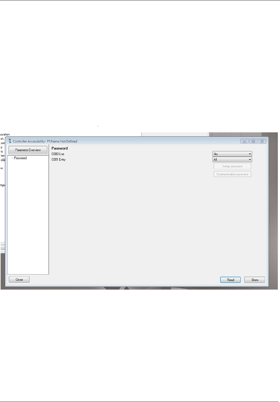
All messages
99 (285)
5.3.18.5 PF Accessibility Configuration
Below is shown where in TTPF the configuration of accessibility to PF program creation shall be set
for those controllers that use password accessibility function.
If a password is NOT set the program download and creation should be possible to do. If a password
IS SET the creation should not be able to do without prompting for a password in the implementation
on the integrator side.
For password handling, the MID 2502 for PF to Integrator password request shall be used, which
shall respond with MID 2503 containing the password text.
5.3.18.6 MID 02502 Password Request
This MID shall be used by the Controller if a password is defined for program download and creation.
It consists only of the header structure.
5.3.18.7 MID 02503 Password Response
This MID shall contain the password text beginning at byte 21 after the header.

All messages
100 (285)
5.3.18.8 Example parameters for PM4000
Table 39 Example parameters for PM4000
Parameter id
(PID)
Name
Description
Xxxxx
Step type
Xxxxx
Speed
Xxxxx
Direction
02000
Toque final target
Xxxxx
Restriction type
Xxxxx
Restriction torque
Etc
5.3.18.9 Example for a simple Pset
A Parameter Set message will be sent like this (only an example, the actual data types and values will
vary).
The example program is a single stage tightening that run to 10 Nm in clock wise direction and is only
showing an extracted part of a longer message where it could be a mandatory to have , for instance,
the tool type included..
Node Type = “001” – Parameter Set
Number of parameters = “002” (for example)
Parameter Id = “02100” – Rotation direction
Length = “001”
Data type = “01” - UI
Unit = “000” – No unit
Step no = “0000”
Data value = “1” – CW
Parameter Id = “02000” – Target torque
Length = “004”
Data type = “03” - Float
Unit = “001” - Nm
Step no = “0000”
Data value = “10.0”
Number of children = “00”
The example message will then have a data field like this:
0010020210000101000000010200000403001000010.000

All messages
101 (285)
5.3.18.10 Example for a tree structure message
A tightening program telegram for a tree structure message will be sent like this (only an example,
the actual data types and values will vary).
The example program is a two-step tightening that run to 10 Nm in the first step and 15 Nm in step 2
and is only showing an extracted part of a longer message where it could be a mandatory to have ,
for instance, the tool type included.
Node Type = “100” – Tightening program
Number of parameters = “000”
Number of children = “02”
Node Type = “101” – Tightening Step
Number of parameters = “001”
Parameter Id = “02000” – Target torque
Length = “004”
Data type = “03” - Float
Unit = “001” - Nm
Step no = “0000”
Data value = “10.0”
Number of children = “00”
Node Type = “101” – Tightening Step
Number of parameters = “001”
Parameter Id = “02000” – Target torque
Length = “004”
Data type = “03” - Float
Unit = “001” - Nm
Step no = “0000”
Data value = “15.0”
Number of children = “00”
The example message will then have a data field like this:
100000021010010200000403001000010.0001010010200000403001000015.000

All messages
102 (285)
5.3.19 MID 2501 Tightening Program Message Upload
This MID contains the program parameter data and is used for upload of an existing program in the PF
controller. The Program request MID 0006 shall be used for fetching this MID.
For continous uploading of programs at changing/versioning the MID 0008 is used.
Typically this MID can be used for getting an already existing configured tightening program, for the
purpose of to have it as a base and doing only the necessary changes for adoptation to another tool
than it was used for.
The variable data field parameters gotten should be dependent on the set Strategy and the Set valid and
used parameters.
Message sent by: Controller
Answer version 1: Acknowledge by Integrator with Link Level MID 9997 if OK, MID 9998 if error
and the Application Level MID 0005, MID 0004 Acknowledge , if sequence number in header <>
0.
Answer version 2: If sequence number isn’t used the Application Level MID 0005, MID 0004
Acknowledge shall be used only.
5.3.19.1 Request for MID 2501 Extra data
Use MID 0006 to request for MID 2501 uploads. Table 3 shows the content in the “Extra data” field
for this MID.
Table 40 MID 2501 Request extra data
Parameter
Size
[byte]
Data
type
Description
Program ID
4
UI
The program identification number. If equal to zero, fetch all node type
programs.
Node Type
3
UI
The type of the node, see table 2.
Use MID 0008 for subscription of MID 2501 uploads at versioning. Table 3 shows the content in the
“Extra data” field for this MID.
Table 41 MID 2501 Subscription extra data
Parameter
Size
[byte]
Data
type
Description
Program ID
4
UI
The program identification number for a certain Program versioning
upload on given node type. If equal to zero, send any Program that has
been versioned for given node type.


All messages
104 (285)
5.4 Application Mode MIDs
The MID’s in this chapter are related to the Mode selection and follows the pattern for Parameter Sets
(MID 0010-0018).
5.4.1 Functionality
Retrieve all Mode id’s from the controller
Retrieve data for a specific mode
Integrator
Controller
MID 2600, Mode ID upload request
MID 2601, Mode ID upload reply
Integrator
Controller
MID 2602, Mode data upload request
MID 2603, Mode data upload reply
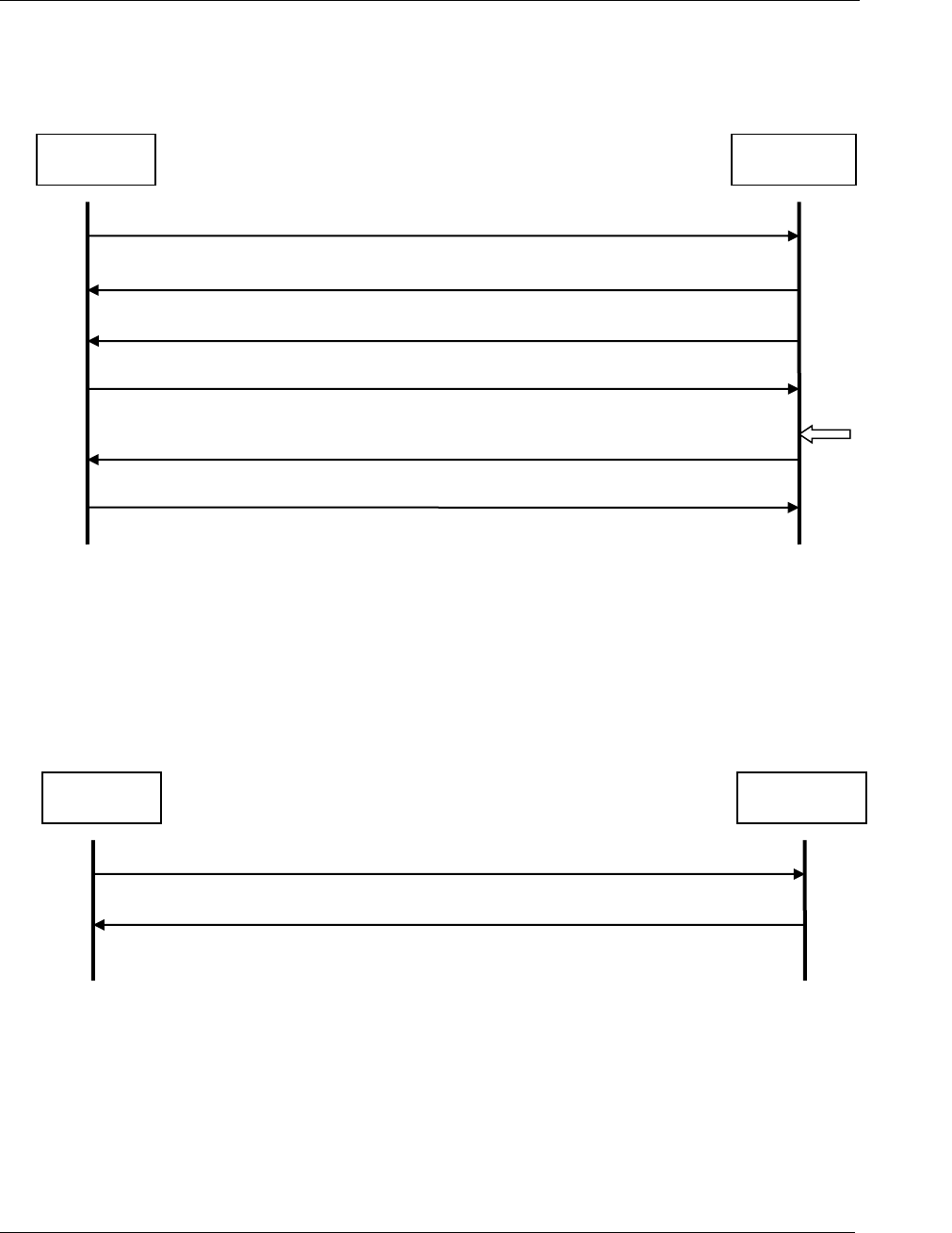
All messages
105 (285)
Get informed when a new mode is selected in the controller
Select a mode in the controller
Integrator
Controller
MID0008, Subscription of MID 2604
MID 2604, Mode selected
MID 2605, Mode selected acknowledge
MID0005, Command accepted
Mode selected
MID 2605, Mode selected acknowledge
MID 2604, Mode selected
Integrator
Controller
MID 2606, Select mode
MID0005, Command accepted

All messages
106 (285)
5.4.2 MID 2600 Mode ID upload request
A request to get the valid mode IDs from the controller.
Message sent by: Integrator
Answer: MID 2601 Mode ID upload reply
Data field, MID 2600
No data can be sent in the data filed for this MID.
5.4.3 MID 2601 Mode ID upload reply
The transmission of all the valid mode IDs of the controller.
Message sent by: Controller
Answer: None
Data field, MID
Table 42 MID 2601 data, revision 1
Parameter
Size
[byte]
Data
type
Description
The number of modes (N mode)
3
UI
Number of modes in the controller
Mode data, will
repeat N mode times
Mode ID
4
UI
Mode id
Mode Name
100
S
Mode name
5.4.4 MID 2602 Mode data upload request
Request to upload mode data from the controller.
Message sent by: Integrator
Answer: MID 2603 Mode data upload reply, or
MID 0004 Command error, Parameter set not present
Data field, MID 2602
Table 43 MID 2602 data, revision 1
Parameter
Size
[byte]
Data
type
Description
Mode ID
4
UI
Mode id
5.4.5 MID 2603 Mode data upload reply
Upload of mode data reply.
Message sent by: Controller
Answer: None

All messages
107 (285)
Data field, MID 2603
Table 44 MID 2603 data, revision 1
Parameter
Size
[byte]
Data
type
Description
Mode ID
4
UI
Mode id
Date
19
T
Date of last change in current mode.
No. bolts
3
UI
Number of bolts in the mode
Bolt data, will
repeat Nbolt times
Pset id
3
UI
Parameter set id, range: 000-999
Spindle ID
3
UI
Spindle id, range: 000-999
5.4.6 MID 2604 Mode selected
A new mode is selected in the controller. The message includes the ID of the mode selected as well as
the date and time of the last change in the parameter set settings.
Message sent by: Controller
Answer: MID 0016 New parameter set selected acknowledge
Subscription, MID 2604
Use MID 0008 to start subscription. Note that the immediate response is MID 0005 Command
accepted and MID 2604 Mode selected.
Data field, MID
Table 45 MID 2604, revision 1
Parameter
Size
[byte]
Data
type
Description
Mode ID
4
UI
Mode id
Date of last change
in mode setting.
19
T
Date of last change in current mode.
No. bolts
3
UI
Number of bolts in the mode

All messages
108 (285)
5.4.7 MID 2605 Mode selected acknowledge
Acknowledgement for a new mode selected.
Message sent by: Integrator
Answer: None
Data field, MID
No data can be sent in the data filed for this MID.
5.4.8 MID 2606 Select Mode
Select a parameter set.
Message sent by: Integrator
Answer: MID 0005 Command accepted or
MID 0004 Command error, Parameter set cannot be set
Data field, MID 2606
Table 46 MID 2606 data, revision 1
Parameter
Size
[byte]
Data
type
Description
Mode ID
4
UI
Mode to be selected.

All messages
109 (285)
5.5 Application Job messages
5.5.1 MID 0030 Job ID upload request
This is a request for a transmission of all the valid Job IDs of the controller. The result of this
command is a transmission of all the valid Job IDs.
Message sent by: Integrator.
Answer: MID 0031 Job ID upload reply
For header description see section 2.2.2!
5.5.2 MID 0031 Job ID upload reply
The transmission of all the valid Job IDs of the controller. The data field contains the number of valid
Jobs currently present in the controller, and the ID of each Job.
Message sent by: Controller
Answer: None
Example revision 1: Job 1 and 2 are present in the controller.
00260031001 020102NUL
Example revision 2: Job 1 and 2 are present in the controller.
00290031002 00200010002NUL
For header description see section 2.2.2!
Table 47 MID 0031 Revision 1
Parameter
Byte
Value
Number of Jobs
21-22
Two ASCII digits, range 00-99.
Job ID of each Job present
in the controller
23-(22 +
nof Jobs
x 2)
Two ASCII digits for each Job. Range: 00-99.
Table 48 MID 0031 Revision 2

All messages
110 (285)
Parameter
Byte
Value
Number of Jobs
21-24
Four ASCII digits, range 0000-9999.
Job ID of each Job present
in the controller
25-(24 +
nof Jobs
x 4)
Four ASCII digits for each Job. Range: 0000-9999.

All messages
111 (285)
5.5.3 MID 0032 Job data upload request
Request to upload the data for a specific Job from the controller.
Message sent by: Integrator
Answer: MID 0033 Job data upload or
MID 0004 Command error, Job ID not present
Example: Upload Job data for Job 1
00220032 01NUL
For header description see section 2.2.2!
Table 49 MID 0032 Revision 1
Parameter
Byte
Value
Job ID
21-22
Two ASCII digits for the Job Id. Range: 00-99.
Table 50 MID 0032 Revision 2 and 3
Parameter
Byte
Value
Job ID
21-24
Four ASCII digits for the Job ID. Range: 0000-9999.

All messages
112 (285)
5.5.4 MID 0033 Job data upload reply
This message is sent as a reply to the MID 0032 Job data request.
Message sent by: Controller
Answer: None
For header description see section 2.2.2!
Table 51 MID 0033 Job data Revision 1
Parameter
Byte
Value
Job ID
21-22
01
23-24
The Job ID is specified by two ASCII characters.
Range: 00-99
Job name
25-26
02
27-51
25 ASCII characters.
Forced order
52-53
03
54
One ASCII character:
0=free order, 1=forced order, 2=free and forced
Max time for first tightening
55-56
04
57-60
Four ASCII digits, range 0000-9999,
0000=not used
Max time to complete Job
61-62
05
63-67
Five ASCII digits, range 00000-99999,
00000=not used
Job batch mode/
batch count type
68-69
06
70
The Job batch mode is the way to count the
tightening in a Job; only the OK or both OK and NOK.
One ASCII character.
0=only the OK tightenings are counted
1=both the OK and NOK tightenings are counted
Lock at Job done
71-72
07
73
One ASCII character: 0=No, 1=Yes
Use line control
74-75
08
76
One ASCII character: 0=No, 1=Yes
Repeat Job
77-78
09
79
One ASCII character: 0=No, 1=Yes
Tool loosening
80-81
10
82
Tool loosening. One ASCII character.
0=Enable, 1=Disable, 2=Enable only on NOK
tightening
Reserved
83-84
11
85
Reserved for Job repair. One ASCII character.
0=E, 1=G
Number of parameter sets
86-87
12

All messages
113 (285)
Parameter
Byte
Value
88-89
The number of parameter sets in the Job list, defined
by two ASCII characters, range 00-99.
Job list
90-91
13
92-
N x 12
A list of parameter sets (N=value from parameter
“Number of parameter sets”, max 50).
Each parameter set is defined by a number of
parameters separated by “:” and terminated by “;” (12
bytes) according to:
[Channel-ID]:[Type-ID]:[AutoValue]:[BatchSize];
Channel-ID = two ASCII characters, range 00-99
Type ID = parameter set ID or Multistage ID, three
ASCII characters, range 000-999
Auto Value = One ASCII character, 1 or 0, 1=for Auto
Next Change,
BatchSize = Two ASCII characters, range 00-99
Example: 15:011:0:22;
Table 52 MID 0033 Job data Revision 2
Parameter
Byte
Value
Job ID
21-22
01
23-26
The Job ID is specified by four ASCII characters.
Range: 0000-9999
Job name
27-28
02
29-53
25 ASCII characters.
Forced order
54-55
03
56
One ASCII character:
0=free order, 1=forced order, 2=free and forced
Max time for first tightening
57-58
04
59-62
Four ASCII digits, range 0000-9999,
0000=not used
Max time to complete Job
63-64
05
65-69
Five ASCII digits, range 00000-99999,
00000=not used
Job batch mode/
batch count type
70-71
06
72
The Job batch mode is the way to count the
tightening in a Job; only the OK or both OK and NOK.
One ASCII character.
0=only the OK tightenings are counted
1=both the OK and NOK tightenings are counted
Lock at Job done
73-74
07
75
One ASCII character: 0=No, 1=Yes
Use line control
76-77
08
78
One ASCII character: 0=No, 1=Yes
Repeat Job
79-80
09
81
One ASCII character: 0=No, 1=Yes
Tool loosening
82-83
10

All messages
114 (285)
Parameter
Byte
Value
84
Tool loosening. One ASCII character.
0=Enable, 1=Disable, 2=Enable only on NOK
tightening
Reserved
85-86
11
87
Reserved for Job repair. One ASCII character.
0=E, 1=G
Number of parameter sets
88-89
12
90-91
The number of parameter sets in the Job list, defined
by two ASCII characters, range 00-99.
Job list
92-93
13
94-
N x 12
A list of parameter sets (N=value from parameter
“Number of parameter sets”, max 50).
Each parameter set is defined by a number of
parameters separated by “:” and terminated by “;” (12
bytes) according to:
[Channel-ID]:[Type-ID]:[AutoValue]:[BatchSize];
Channel-ID = two ASCII characters, range 00-99
Type ID = parameter set ID or Multistage ID, three
ASCII characters, range 000-999
Auto Value = One ASCII character, 1 or 0, 1=for Auto
Next Change,
BatchSize = Two ASCII characters, range 00-99
Example: 15:011:0:22;

All messages
115 (285)
Table 53 MID 0033 Job data Revision 3
Parameter
Byte
Value
Job list
94-95
13
96-
N x 44
A list of parameter sets (N=value from parameter
“Number of parameter sets”, max 50).
Each parameter set is defined by a number of
parameters separated by “:” and terminated by “;” (41
bytes) according to:
[Channel-ID]:[Type-
ID]:[AutoValue]:[BatchSize]:[Socket]:[Job step
name]:[Job step type];
Channel-ID = two ASCII characters, range 00-99
Type ID = parameter set ID or Multistage ID, three
ASCII characters, range 000-999
Auto Value = One ASCII character, 1 or 0, 1=for Auto
Next Change,
BatchSize = Two ASCII characters, range 00-99
Socket = Two ASCII characters, range 00-99 (socket
used)
Job step name = 25 ASCII characters
Job step type = Two ASCII characters, range 00-99
Batch step = 1
Reserved = 2-6
Example: 15:011:0:22:02:Front axle :01;
Observe that “Socket”, “Job step name” and “Job
step type” are NOT supported from PF4000, hence
set to zeroes only.
5.5.5 MID 0034 Job info subscribe
A subscription for the Job info. MID 0035 Job info is sent to the integrator when a new Job is selected
and after each tightening performed during the Job.
Message sent by: Integrator
Answer: MID 0005 Command accepted or
MID 0004 Command error, Job info subscription already exists
For header description see section 2.2.2!
5.5.6 MID 0035 Job info
The Job info subscriber will receive a Job info message after a Job has been selected and after each
tightening performed in the Job. The Job info consists of the ID of the currently running Job, the Job
status, the Job batch mode, the Job batch size and the Job batch counter.
Message sent by: Controller
Answer: MID 0036 Job info Acknowledge
Example: Job info for Job 1
00630035 0101020030040008050003062001-12-01:20:12:45NUL

All messages
116 (285)
For header description see section 2.2.2!
Table 54 MID 0035 Job info Revision 1
Parameter
Byte
Value
Job ID
21-22
01
23-24
The Job ID is specified by two ASCII characters,
range 00-99
Job status
25-26
02
27
The Job batch status is specified by one ASCII
character.
0=Job not completed, 1=Job OK, 2=Job NOK.
Job batch mode
28-29
03
30
The Job batch mode is the way to count the
tightening in a Job only the OK or both OK and NOK.
One ASCII character
0= only the OK tightenings are counted
1= both the OK and NOK tightenings are counted
Job batch size
31-32
04
33-36
This parameter gives the total number of tightening in
the Job. The Job batch size is four bytes long. Four
ASCII characters, range 0000-9999.
Job batch counter
37-38
05
39-42
This parameter gives the current value of the Job
batch counter. The Job is completed when the Job
batch counter is equal to the Job batch size. The Job
batch counter is four bytes long. Four ASCII
characters, range 0000-9999.
Time stamp
43-44
06
45-63
Time stamp for the Job info. The time stamp is 19
bytes long and is specified by 19 ASCII characters
YYYY-MM-DD:HH:MM:SS.
Table 55 MID 0035 Job info Revision 2
Parameter
Byte
Value
Job ID
21-22
01
23-26
The Job ID is specified by four ASCII characters,
range 0000-9999
Job status
27-28
02
29
The Job batch status is specified by one ASCII
character.
0=Job not completed, 1=Job OK, 2=Job NOK.
Job batch mode
30-31
03
32
The Job batch mode is the way to count the
tightening in a Job only the OK or both OK and NOK.
One ASCII character
0= only the OK tightenings are counted
1= both the OK and NOK tightenings are counted
Job batch size
33-34
04

All messages
117 (285)
Parameter
Byte
Value
35-37
This parameter gives the total number of tightening in
the Job. The Job batch size is four bytes long. Four
ASCII characters, range 0000-9999.
Job batch counter
39-40
05
41-44
This parameter gives the current value of the Job
batch counter. The Job is completed when the Job
batch counter is equal to the Job batch size. The Job
batch counter is four bytes long. Four ASCII
characters, range 0000-9999.
Time stamp
45-46
06
47-65
Time stamp for the Job info. The time stamp is 19
bytes long and is specified by 19 ASCII characters
YYYY-MM-DD:HH:MM:SS.

All messages
118 (285)
Table 56 MID 0035 Job info Revision 3
Parameter
Byte
Value
Job current step
66-67
07
68-70
The number of the step currently executed in the job.
3 bytes long, 3 ASCII characters range 000-999. For
PF4000, PF3000 is zero reported.
Job total number of steps
71-72
08
73-75
The total number of steps in the job. 3 bytes long, 3
ASCII characters range 000-999. For PF4000,
PF3000 is zero reported.
Job step type
76-77
09
78-79
Job step type = Two ASCII characters, range 00-99
Batch step = 1
Reserved = 2-6
For PF4000, PF3000 is zero reported.
Table 57 MID 0035 Job info Revision 4
Parameter
Byte
Value
Job ID
21-22
01
23-26
The Job ID is specified by four ASCII characters,
range 0000-9999
Job status
27-28
02
29
The Job batch status is specified by one ASCII
character.
0=Job not completed, 1=Job OK, 2=Job NOK, 3=Job
ABORTED
Job batch mode
301-31
03
32
The Job batch mode is the way to count the
tightening in a Job only the OK or both OK and NOK.
One ASCII character
0= only the OK tightenings are counted
1= both the OK and NOK tightenings are counted
Job batch size
33-34
04
35-38
This parameter gives the total number of tightening in
the Job. The Job batch size is four bytes long. Four
ASCII characters, range 0000-9999.
Job batch counter
39-40
05
41-44
This parameter gives the current value of the Job
batch counter. The Job is completed when the Job
batch counter is equal to the Job batch size. The Job
batch counter is four bytes long. Four ASCII
characters, range 0000-9999.
Time stamp
45-46
06
47-65
Time stamp for the Job info. The time stamp is 19
bytes long and is specified by 19 ASCII characters
YYYY-MM-DD:HH:MM:SS.
Job current step
66-67
07
68-70
N/A
Job total number of steps
71-72
08

All messages
119 (285)
Parameter
Byte
Value
73-75
N/A
Job step type
76-77
09
78-79
N/A
Job tightening status
80-81
10
82-83
The Job tightening status is specified by two ASCII
character.
0=JobTight OFF, 1=JobTight OK, 2=JobTight NOK,
3=JobTight ABORTED, 4= JobTight INCREMENTED,
5=JobTight DECREMENTED, 6=JobTight
BYPASSED,
7=JobTight RESET BATCH, 8=JobTight
LOOSENING,
9=JobTight FREE BATCH, 10=JobTight JOB
ABORTED
Table 58 MID 0035 Job info Revision 5
Parameter
Byte
Value
Job sequence number
84-85
11
86-90
The Job sequence number is unique for each Job. All
tightenings performed in the same Job are stamped
with the same Job sequence number. It is specified
by five ASCII digits. Range: 00000-65535.
VIN number
91-92
12
93-117
The VIN number is 25 bytes long and is specified by
25 ASCII characters.
Identifier result part 2
118-119
13
120-144
The identifier result part 2 is 25 bytes long and is
specified by 25 ASCII characters.
Identifier result part 3
145-146
14
147-171
The identifier result part 3 is 25 bytes long and is
specified by 25 ASCII characters.
Identifier result part 4
172-173
15
174-198
The identifier result part 4 is 25 bytes long and is
specified by 25 ASCII characters.

All messages
120 (285)
5.5.7 MID 0036 Job info acknowledge
Acknowledgement of a Job info message.
Message sent by: Integrator
Answer: None
For header description see section 2.2.2!
5.5.8 MID 0037 Job info unsubscribe
Reset the subscription for a Job info message.
Message sent by: Integrator
Answer: MID 0005 Command accepted or
MID 0004 Command error, Job info subscription does not exist
For header description see section 2.2.2!
5.5.9 MID 0038 Select Job
Message to select Job. If the requested ID is not present in the controller, then the command will not
be performed.
Message sent by: Integrator
Answer: MID 0005 Command accepted or
MID 0004 Command error, Job can not be set, or Invalid data
For header description see section 2.2.2!
Table 59 MID 0038 Job ID, revision 1
Parameter
Byte
Value
Job ID
21-22
The Job ID is specified by two ASCII characters. Range: 00-99
Table 60 MID 0038 Job ID, revision 2
Parameter
Byte
Value
Job ID
21-24
The Job ID is specified by four ASCII characters.
Range: 0000-9999
5.5.10 MID 0039 Job restart
Job restart message.

All messages
121 (285)
Message sent by: Integrator
Answer: MID 0005 Command accepted or
MID 0004 Command error, Job not running, or Invalid data
Example: Restart Job 1
00220039 01NUL
For header description see section 2.2.2!
Table 61 MID 0039 Revision 1
Parameter
Byte
Value
Job ID
21-22
Two ASCII digits for the Job Id. Range: 00-99.
Table 62 MID 0039 Revision 2
Parameter
Byte
Value
Job ID
21-24
Four ASCII digits for the Job ID. Range: 0000-9999.

All messages
122 (285)
5.6 Application Tool messages
5.6.1 MID 0040 Tool data upload request
A request for some of the data stored in the tool. The result of this command is the transmission of the
tool data.
Message sent by: Integrator
Answer: MID 0041 Tool data upload reply
For header description see section 2.2.2!
5.6.2 MID 0041 Tool data upload reply
Upload of tool data from the controller.
Message sent by: Controller
Answer: None
Example: Tool data
00810041 01C341212 02548796
032001-05-07:13:24:5404670919 NUL
For header description see section 2.2.2!
Table 63 MID 0041 Tool data, revision 1
Parameter
Byte
Value
Tool serial number
21-22
01
23-36
14 ASCII characters
Tool number of tightening
37-38
02
39-48
10 ASCII digits. Max 4294967295
Last calibration date
49-50
03
51-69
19 ASCII characters. YYYY-MM-DD:HH:MM:SS
Controller serial number =
Ford. RBU Serial = Normal
70-71
04
72-81
10 ASCII characters
Table 64 MID 0041 Tool data, additions for revision 2
Parameter
Byte
Value
Calibration value
82-83
05
84-89
The tool calibration value is multiplied by 100 and
sent as an integer (2 decimals truncated). Six ASCII
digits.

All messages
123 (285)
Last service date
90-91
06
92-110
YYYY-MM-DD:HH:MM:SS
Tightenings since service
111-112
07
113-122
The number of tightenings since last service is
specified by 10 ASCII digits. Max 4294967295.
Tool type
123-124
08
125-126
The tool type is specified by 2 ASCII digits:
00=No Tool, 01=S-tool, 02=DS-tool, 03=Ref.
transducer, 04=ST-tool, 05=EP-tool, 06=ETX-tool,
07=SL-tool, 08=DL-tool, 09=IRC Offline, 10=STB-
tool, 11=QST-tool, 12=STT-tool, 13=STwrench, 14 =
ES-tool
Motor size
127-128
09
129-130
The motor size is specified by 2 ASCII digits,
range 00-99.
00 = no motor, 01-99 = motor size xx in Atlas Copco
nomenclature, or motor size = 10xx in Atlas Copco
nomenclature (certain numbers correspond to 2
different motor sizes, for example 62 for both motor
size 62 and motor size 1062)
Open end data
131-132
10
133-135
The open end data is specified by 3 ASCII digits.
The first digit represents the “use open end”: 1=true,
0=false.
The second digit indicates the tightening direction:
0=CW, 1=CCW.
The third digit indicates motor rotation: 0=normal,
1=inverted.
Controller software version
136-137
11
138-156
The software version is specified by 19 ASCII
characters.
Table 65 MID 0041 Tool data, additions for revision 3
Parameter
Byte
Value
Tool max torque
157-158
12
159-164
The tool max toque value is multiplied by 100 and
sent as an integer (2 decimals truncated). Six ASCII
digits.
Gear ratio
165-166
13
167-172
The gear ratio value is multiplied by 100 and sent as
an integer (2 decimals truncated). Six ASCII digits.
Tool full speed
173-174
14
175-180
The tool full speed value is multiplied by 100 and sent
as an integer (2 decimals truncated). Six ASCII digits.
Table 66 MID 0041 Tool data, additions for revision 4

All messages
124 (285)
Parameter
Byte
Value
Primary tool
181-182
15
183-184
Primary tool. The primary tool is two byte-long and
specified by two ASCII digits.
01=Cable (invalid for IRC-controller), 02=IRC-B,
03=IRC-W
Table 67 MID 0041 Tool data, additions for revision 5
Parameter
Byte
Value
Tool model
185-186
16
187-198
12 ASCII characters with padding at the end of the
string if needed. The padding is done spaces.

All messages
125 (285)
5.6.3 MID 0042 Disable tool
Disable tool.
Message sent by: Integrator
Answer: MID 0005 Command accepted
For header description see section 2.2.2!
5.6.4 MID 0043 Enable tool
Enable tool.
Message sent by: Integrator
Answer: MID 0005 Command accepted
For header description see section 2.2.2!

All messages
126 (285)
5.6.5 MID 0044 Disconnect tool request
This command is sent by the integrator in order to request the possibility to disconnect the tool from
the controller. The command is rejected if the tool is currently used.
When the command is accepted the operator can disconnect the tool and replace it (hot swap).
Message sent by: Integrator
Answer: MID 0005 Command accepted or
MID 0004 Command error, Tool currently in use
For header description see section 2.2.2!
5.6.6 MID 0045 Set calibration value request
This message is sent by the integrator in order to set the calibration value of the tool.
Message sent by: Integrator
Answer: MID 0005 Command accepted or
MID 0004 Command error, Calibration failed
Example: Request for setting a calibration value of 35,5 Nm.
00310045 01102003550NUL
For header description see section 2.2.2!
Table 68 MID 0045 Calibration data
Parameter
Byte
Value
Calibration value Unit
21-22
01
23
The unit in which the calibration value is sent. The calibration
value unit is one byte long and specified by one ASCII digit.
1=Nm, 2=Lbf.ft, 3=Lbf.In, 4=Kpm, 5= Ncm
Calibration value
24-25
02
26-31
The calibration value is multiplied by 100 and sent as an integer
(2 decimals truncated). The calibration value is six bytes long and
is specified by six ASCII digits.
5.6.7 MID 0046 Set primary tool request
This message is sent by the integrator in order to set tool data.
Warning 1: this MID requires programming control (see 4.4 Programming control).
Warning 2: the new configuration will not be active until the next controller reboot!
Message sent by: Integrator

All messages
127 (285)
Answer: MID 0005 Command accepted or
MID 0004 Command error, Programming control not granted
or Invalid data (value not supported by controller)
Example: Request for setting primary tool to Cable.
00240046 0101NUL
For header description see section 2.2.2!
Table 69 MID 0046 Primary tool, revision 000-001
Parameter
Byte
Value
Primary tool
21-22
01
23-24
Primary tool. The primary tool is two byte-long and specified by
two ASCII digits.
01=Cable (invalid for IRC-controller), 02=IRC-B, 03=IRC-W
5.6.8 MID 0047 Tool Pairing handling
This message is sent by the integrator in order to Pair tools, to abort ongoing pairing, to
Abort/Disconnect established connection and request for pairing status of the IRC-B or IRC-W tool
types. At pairing handling type, Start Pairing and Pairing Abort or Disconnect the controller must take
program control and release when finished. MID 0048 will be uploaded during the pairing process at
each change of the pairing stage.
Message sent by: Integrator
Answer: MID 0005 Command accepted at pairing status ACCEPTED
MID 0004 Command error. See error codes.
MID 0048 Pairing status during the pairing process
For header description see section 2.2.2!
Table 70 MID 0047 Tool Pairing handling, revision 000-001
Parameter
Byte
Value
Pairing handling type
21-22
01
23-24
Type of handling, a two byte-long and specified by two ASCII
digits.
01 = Start Pairing
02 = Pairing Abort or Disconnect
03 = Fetch latest pairing status.

All messages
128 (285)
5.6.9 MID 0048 Tool Pairing status
This message is sent by the controller in order to report the current status of the tool pairing.
Message sent by: Controller
Answer: N/A
For header description see section 2.2.2!
Table 71 MID 0048 Tool Pairing status Revision 000-001
Parameter
Byte
Value
Pairing status
21-22
01
23-24
Status of the tool pairing, a two byte-long and specified by two
ASCII digits.
00 = UNDEFINED. Tool not mounted yet
01= ACCEPTED. Pairing allowed and started
02=INQUIRY. Normal pairing sequence as OK
03=SENDPIN. -“- -“-
04=PINOK -“- -“-
05=READY -“- -“-
06=ABORTED. Ongoing Pairing aborted.
07=DENIED. Pairing not allowed. Program control.
08=FAILED. Pairing attempt failed
09=UNREADY. Pairing never done before or disconnected
Time stamp
25-26
02
27-45
Time stamp for each status change or time for fetch. It is 19 bytes
long and is specified by 19 ASCII characters
(YYYY-MM-DD:HH:MM:SS).

All messages
129 (285)
5.6.10 MID 0700 Tightening data download status
Used by controller to upload the status of tightening data download to an radio connected tool.
Must be subscribed for by generic MID 0008 and unsubscribed for with generic MID 0009.
No extra data is needed and no historical data is applicable.
Message sent by: Controller
Answer: MID 0005
For header description see section 2.2.2!
Table 72MID 0700 Data
Message part
Parameter
Byte
Value
Data field
Tightening data
download status in tool
21-23
Number of variable parameters.
Variable parameters
Tightening data
download status in tool
23-x
Tightening data tool download status. See variable
parameters.

All messages
130 (285)
5.7 Application VIN Messages
5.7.1 MID 0050 Vehicle ID Number download request
This message is replaced by MID 0150. MID 0050 is still supported.
Used by the integrator to send a VIN number to the controller.
Message sent by: Integrator
Answer: MID 0005 Command accepted or
MID 0004 Command error, VIN input source not granted
For header description see section 2.2.2!
Table 73 MID 0050 Revision 1
Parameter
Byte
Value
VIN number
21-max 45
Dynamic with max 25 ASCII characters.
5.7.2 MID 0051 Vehicle ID Number subscribe
This message is used by the integrator to set a subscription for the current identifiers of the tightening
result.
The tightening result can be stamped with up to four identifiers:
VIN number
Identifier result part 2
Identifier result part 3
Identifier result part 4
The identifiers are received by the controller from several input sources, for example serial, Ethernet,
or field bus.
In revision 1 of the MID 0052 Vehicle ID Number, only the VIN number is transmitted. In revision 2, all
four possible identifiers are transmitted.
Message sent by: Integrator
Answer: MID 0005 Command accepted or
MID 0004 Command error, VIN subscription already exists
For header description see section 2.2.2!

All messages
131 (285)
5.7.3 MID 0052 Vehicle ID Number
Transmission of the current identifiers of the tightening by the controller to the subscriber.
The tightening result can be stamped with up to four identifiers:
VIN number (identifier result part 1)
Identifier result part 2
Identifier result part 3
Identifier result part 4
The identifiers are received by the controller from several input sources, for example serial, Ethernet,
or field bus.
Message sent by: Controller
Answer: MID 0053 Vehicle ID Number acknowledge
For header description see section 2.2.2!
Table 74 MID 0052 Identifier data, revision 1
Parameter
Byte
Value
VIN number
21-45
The VIN number is 25 bytes long and is specified by 25 ASCII
characters.
Note! Only for PowerMACS and rev 000-001, the VIN number
can be up to 40 bytes long. Minimum number of bytes is always
25.
Table 75 MID 0052 Identifier data, additions for revision 2
Parameter
Byte
Value
VIN number
21-22
01
23-47
The VIN number is 25 bytes long and is specified by 25 ASCII
characters.
Note! Only for PowerMACS and rev 000-001, the VIN number
can be up to 40 bytes long. Minimum number of bytes is always
25.
Identifier result part 2
48-49
02
50-74
The identifier result part 2 is 25 bytes long and is specified by 25
ASCII characters.
Identifier result part 3
75-76
03
77-91
The identifier result part 3 is 25 bytes long and is specified by 25
ASCII characters.
Identifier result part 4
92-93
04
94-128
The identifier result part 4 is 25 bytes long and is specified by 25
ASCII characters.

All messages
132 (285)
5.7.4 MID 0053 Vehicle ID Number acknowledge
Vehicle ID Number acknowledge.
Message sent by: Integrator
Answer: None
For header description see section 2.2.2!
5.7.5 MID 0054 Vehicle ID Number unsubscribe
Reset the subscription for the current tightening identifiers.
Message sent by: Integrator
Answer: MID 0005 Command accepted or
MID 0004 Command error, VIN subscription does not exist
For header description see section 2.2.2!

All messages
133 (285)
5.8 Application Tightening result messages
5.8.1 MID 0060 Last tightening result data subscribe
Set the subscription for the result tightenings. The result of this command will be the transmission of
the tightening result after the tightening is performed (push function). The MID revision in the header
is used to subscribe to different revisions of MID 0061 Last tightening result data upload reply.
Message sent by: Integrator
Answer: MID 0005 Command accepted or
MID 0004 Command error, Last tightening subscription already exists or
MID revision not supported
For header description see section 2.2.2!
5.8.2 MID 0061 Last tightening result data
Upload the last tightening result. The following tables show the revisions available:
Message sent by: Controller
Answer: MID 0062 Last tightening result data acknowledge
Example: MID 0061 Last tightening result data upload reply, revision 1
023100610010 010001020103airbag7
04KPOL3456JKLO897 05000600307000008000009010011112000840
130014001400120015000739160000017099991800000
1900000202001-06-02:09:54:09212001-05-29:12:34:3322123345675 NUL
For header description see section 2.2.2!

All messages
134 (285)
Table 76 MID 0061 Revision 1
Parameter
Byte
Value
Cell ID
21-22
01
23-26
The cell ID is four bytes long and specified by four
ASCII digits. Range: 0000-9999.
Channel ID
27-28
02
29-30
The channel ID is two bytes long and specified by
two ASCII digits. Range: 00-99.
Torque controller Name
31-32
03
33-57
The controller name is 25 bytes long and is specified
by 25 ASCII characters.
VIN Number
58-59
04
60-84
The VIN number is 25 bytes long and is specified by
25 ASCII characters.
Job ID
85-86
05
87-88
The Job ID is two bytes long and specified by two
ASCII digits. Range: 00-99
Parameter set ID
89-90
06
91-93
The parameter set ID is three bytes long and
specified by three ASCII digits. Range: 000-999.
Batch size
94-95
07
96-99
This parameter gives the total number of tightening in
the batch. The batch size is four bytes long and
specified by four ASCII digits. Range: 0000-9999.
Batch counter
100-101
08
102-105
The batch counter information is four bytes long
specifying and specified by four ASCII digits. Range:
0000-9999.
Tightening Status
106-107
09
108
The tightening status is one byte long and specified
by one ASCII digit. 0=tightening NOK, 1=tightening
OK.
Torque status
109-110
10
111
0=Low, 1=OK, 2=High
Angle status
112-113
11
114
0=Low, 1=OK, 2=High
Torque Min limit
115-116
12
117-122
The torque min limit is multiplied by 100 and sent as
an integer (2 decimals truncated). It is six bytes long
and is specified by six ASCII digits.
Torque Max limit
123-124
13
125-130
The torque max limit is multiplied by 100 and sent as
an integer (2 decimals truncated). It is six bytes long
and is specified by six ASCII digits.
Torque final target
131-132
14

All messages
135 (285)
133-138
The torque final target is multiplied by 100 and sent
as an integer (2 decimals truncated). It is six bytes
long and is specified by six ASCII digits.
Torque
139-140
15
141-146
The torque value is multiplied by 100 and sent as an
integer (2 decimals truncated). It is six bytes long and
is specified by six ASCII digits.
Angle Min
147-148
16
149-153
The angle min value in degrees. Each turn
represents 360 degrees. It is five bytes long and
specified by five ASCII digits. Range: 00000-99999.
Angle Max
154-155
17
156-160
The angle max value in degrees. Each turn
represents 360 degrees. It is five bytes long and
specified by five ASCII digits. Range: 00000-99999.
Final Angle
Target
161-162
18
163-167
The target angle value in degrees. Each turn
represents 360 degrees. It is five bytes long and
specified by five ASCII digits. Range: 00000-99999.
Angle
168-169
19
170-174
The turning angle value in degrees. Each turn
represents 360 degrees. It is five bytes long and
specified by five ASCII digits. Range: 00000-99999.
Time stamp
175-176
20
177-195
Time stamp for each tightening. It is 19 bytes long
and is specified by 19 ASCII characters
(YYYY-MM-DD:HH:MM:SS).
Date/time of last change in
parameter set settings
196-197
21
198-216
Time stamp for the last change in the current
parameter set settings. It is 19 bytes long and is
specified by 19 ASCII characters (YYYY-MM-
DD:HH:MM:SS).
Batch status
217-218
22
219
The batch status is specified by one ASCII character.
0=batch NOK (batch not completed), 1=batch OK,
2=batch not used.
Tightening ID
220-221
23
222-231
The tightening ID is a unique ID for each tightening
result. It is incremented after each tightening. 10
ASCII digits. Max 4294967295

All messages
136 (285)
Table 59 MID 0061 Revision 2
Parameter
Byte
Value
Cell ID
21-22
01
23-26
The cell ID is four bytes long and specified by four
ASCII digits. Range: 0000-9999.
Channel ID
27-28
02
29-30
The channel ID is two bytes long and specified by
two ASCII digits. Range: 00-99.
Torque controller Name
31-32
03
33-57
The controller name is 25 bytes long and is specified
by 25 ASCII characters.
VIN Number
58-59
04
60-84
The VIN number is 25 bytes long and is specified by
25 ASCII characters.
Job ID
85-86
05
87-90
The Job ID is four bytes long and specified by four
ASCII digits. Range: 0000-9999
Parameter set number
91-92
06
93-95
The parameter set ID is three bytes long and
specified by three ASCII digits. Range: 000-999.
Strategy
96-97
07
98-99
The strategies currently run by the controller. It is two
bytes long and specified by two ASCII digits. Range:
00-99.
The corresponding strategies are :
01=Torque control, 02=Torque control / angle
monitoring,
03=Torque control / angle control AND,
04=Angle control / torque monitoring, 05=DS control,
06=DS control torque monitoring, 07=Reverse angle,
08=Reverse torque, 09=Click wrench,
10=Rotate spindle forward, 11=Torque control angle
control OR,
12=Rotate spindle reverse, 13=Home position
forward,
14=EP Monitoring, 15=Yield, 16=EP Fixed, 17=EP
Control,
18=EP Angle shutoff, 19=Yield / torque control OR,
20=Snug gradient, 21=Residual torque / Time
22=Residual torque / Angle, 23=Breakaway peak
24=Loose and tightening, 25=Home position reverse,
26=PVT comp with Snug
99=No strategy
Strategy options
100-101
08

All messages
137 (285)
Parameter
Byte
Value
102-106
Five bytes long bit field.
Bit 0 Torque
Bit 1 Angle
Bit 2 Batch
Bit 3 PVT Monitoring
Bit 4 PVT Compensate
Bit 5 Self-tap
Bit 6 Rundown
Bit 7 CM
Bit 8 DS control
Bit 9 Click Wrench
Bit 10 RBW Monitoring
Batch size
107-108
09
109-112
This parameter gives the total number of tightening in
the batch. The batch size is four bytes long and
specified by four ASCII digits. Range: 0000-9999.
Batch counter
113-114
10
115-118
The batch counter information is four bytes long
specifying and specified by four ASCII digits. Range:
0000-9999.
Tightening Status
119-120
11
121
The tightening status is one byte long and is specified
by one ASCII digit. 0=tightening NOK, 1=tightening
OK.
Note! For Ford the status is built on certain
“Tightening error status” bits and “Result type”,
see fields below. See Ford appendix for detailed
description.
Batch status
122-123
12
124
The batch status is specified by one ASCII character.
0=batch NOK (batch not completed), 1=batch OK,
2=batch not used.
Torque status
125-126
13
127
0=Low, 1=OK, 2=High
Angle status
128-129
14
130
0=Low, 1=OK, 2=High
Rundown angle status
131-132
15
133
0=Low, 1=OK, 2=High
Current Monitoring Status
134-135
16
136
0=Low, 1=OK, 2=High
Self-tap status
137-138
17
139
0=Low, 1=OK, 2=High
Prevail Torque monitoring
status
140-141
18
142
0=Low, 1=OK, 2=High
Prevail Torque compensate
status
143-144
19
145
0=Low, 1=OK, 2=High
Tightening error status
146-147
20

All messages
138 (285)
Parameter
Byte
Value
148-157
Ten bytes long bit field.
Tightening error bits show what went wrong with the
tightening.
Bit 1 Rundown angle max shut off
Bit 2 Rundown angle min shut off
Bit 3 Torque max shut off
Bit 4 Angle max shut off
Bit 5 Self-tap torque max shut off
Bit 6 Self-tap torque min shut off
Bit 7 Prevail torque max shut off
Bit 8 Prevail torque min shut off
Bit 9 Prevail torque compensate overflow
Bit 10 Current monitoring max shut off
Bit 11 Post view torque min torque shut off
Bit 12 Post view torque max torque shut off
Bit 13 Post view torque Angle too small
Bit 14 Trigger lost
Bit 15 Torque less than target
Bit 16 Tool hot
Bit 17 Multistage abort
Bit 18 Rehit
Bit 19 DS measure failed
Bit 20 Current limit reached
Bit 21 End Time out shutoff
Bit 22 Remove fastener limit exceeded
Bit 23 Disable drive
Bit 24 Transducer lost
Bit 25 Transducer shorted
Bit 26 Transducer corrupt
Bit 27 Sync timeout
Bit 28 Dynamic current monitoring min
Bit 29 Dynamic current monitoring max
Bit 30 Angle max monitor
Bit 31 Yield nut off
Bit 32 Yield too few samples
Torque Min limit
158-159
21
160-165
The torque min limit is multiplied by 100 and sent as
an integer (2 decimals truncated). It is six bytes long
and is specified by six ASCII digits.
Torque Max limit
166-167
22
168-173
The torque max limit is multiplied by 100 and sent as
an integer (2 decimals truncated). It is six bytes long
and is specified by six ASCII digits.
Torque final target
174-175
23
176-181
The torque final target is multiplied by 100 and sent
as an integer (2 decimals truncated). It is six bytes
long and is specified by six ASCII digits.
Torque
182-183
24
184-189
The torque value is multiplied by 100 and sent as an
integer (2 decimals truncated). It is six bytes long and
is specified by six ASCII digits.
Angle Min
190-191
25
192-196
The angle min value in degrees. Each turn
represents 360 degrees. It is five bytes long and
specified by five ASCII digits. Range: 00000-99999.

All messages
139 (285)
Parameter
Byte
Value
Angle Max
197-198
26
199-203
The angle max value in degrees. Each turn
represents 360 degrees. It is five bytes long and
specified by five ASCII digits. Range: 00000-99999.
Final Angle
Target
204-205
27
206-210
The target angle value in degrees. Each turn
represents 360 degrees. It is five bytes long and
specified by five ASCII digits. Range: 00000-99999.
Angle
211-212
28
213-217
The turning angle value in degrees. Each turn
represents 360 degrees. It is five bytes long and
specified by five ASCII digits. Range: 00000-99999.
Rundown angle Min
218-219
29
220-224
The tightening angle min value in degrees. Each turn
represents 360 degrees. It is five bytes long and
specified by five ASCII digits. Range: 00000-99999.
Rundown angle Max
225-226
30
227-231
The tightening angle max value in degrees. Each turn
represents 360 degrees. It is five bytes long and
specified by five ASCII digits. Range: 00000-99999.
Rundown angle
232-233
31
234-238
The tightening angle value reached in degrees. Each
turn represents 360 degrees. It is five bytes long and
specified by five ASCII digits. Range: 00000-99999.
Current Monitoring Min
239-240
32
241-243
The current monitoring min limit in percent is three
bytes long and is specified by three ASCII digits.
Range: 000-999.
Current Monitoring Max
244-245
33
246-248
The current monitoring max limit in percent is three
bytes long and is specified by three ASCII digits.
Range: 000-999.
Current Monitoring Value
249-250
34
251-253
The current monitoring value in percent is three bytes
long and is specified by three ASCII digits. Range:
000-999.
Self-tap min
254-255
35
256-261
The self-tap min limit is multiplied by 100 and sent as
an integer (2 decimals truncated). It is six bytes long
and specified by six ASCII digits.
Self-tap max
262-263
36
264-269
The self-tap max limit is multiplied by 100 and sent as
an integer (2 decimals truncated). It is six bytes long
and specified by six ASCII digits.
Self-tap torque
270-271
37
272-277
The self-tap torque is multiplied by 100 and sent as
an integer (2 decimals truncated). It is six bytes long
and specified by six ASCII digits.
Prevail torque monitoring
278-279
38

All messages
140 (285)
Parameter
Byte
Value
min
280-285
The PVTmin limit is multiplied by 100 and sent as an
integer (2 decimals truncated). It is six bytes long and
specified by six ASCII digits.
Prevail torque monitoring
max
286-287
39
288-293
The PVT max limit is multiplied by 100 and sent as
an integer (2 decimals truncated). It is six bytes long
and specified by six ASCII digits.
Prevail torque
294-295
40
296-301
The prevail torque value is multiplied by 100 and sent
as an integer (2 decimals truncated). The prevail
torque is six bytes long and is specified by six ASCII
digits.
Tightening ID
302-303
41
304-313
The tightening ID is a unique ID. It is incremented
after each tightening. It is ten bytes long and
specified by ten ASCII digits. Max 4294967295.
Job sequence number
314-315
42
316-320
The Job sequence number is unique for each Job. All
tightenings performed in the same Job are stamped
with the same Job sequence number. It is specified
by five ASCII digits. Range: 00000-65535.
Sync tightening ID
321-322
43
323-327
The sync tightening ID is a unique ID for each sync
tightening result.
Each individual result of each spindle is stamped with
this ID.
The tightening ID is incremented after each sync
tightening. It is specified by five ASCII digits. Range:
00000-65535.
Tool serial number
328-329
44
330-343
The Tool serial number is specified by 14 ASCII
characters.
Time stamp
344-345
45
346-364
Time stamp for the tightening. It is 19 bytes long and
is specified by 19 ASCII characters
(YYYY-MM-DD:HH:MM:SS).
Date/time of last change in
parameter set settings
365-366
46
367-385
Time stamp for the last change in the current
parameter set settings. It is 19 bytes long and is
specified by 19 ASCII characters (YYYY-MM-
DD:HH:MM:SS).

All messages
141 (285)
Table 77 MID 0061 Revision 3
Parameter
Byte
Value
Parameter set Name
386-387
47
388-412
The parameter set name is 25 bytes long and is
specified by 25 ASCII characters.
Torque values Unit
413-414
48
415
The unit in which the torque values are sent. The
torque values unit is one byte long and is specified by
one ASCII digit.
1=Nm, 2=Lbf.ft, 3=Lbf.In, 4=Kpm
5=Kgf.cm, 6=ozf.in, 7=%, 8= Ncm
Result type
416-417
49
418-419
The result type is two bytes long and specified by two
ASCII digits.
1=Tightening, 2=Loosening, 3=Batch Increment
4=Batch decrement, 5=Bypass parameter set result
6=Abort Job result, 7=Sync tightening,
8=Reference setup
Table 78 MID 0061 Revision 4
Parameter
Byte
Value
Identifier result part 2
420-421
50
422-446
The identifier result part 2 is 25 bytes long and is
specified by 25 ASCII characters.
Identifier result part 3
447-448
51
449-473
The identifier result part 3 is 25 bytes long and is
specified by 25 ASCII characters.
Identifier result part 4
474-475
52
476-500
The identifier result part 4 is 25 bytes long and is
specified by 25 ASCII characters.
Note: The identifier result parts will only be set if the multiple identifier option has been activated in
the controller.
Table 79 MID 0061 Revision 5
Parameter
Byte
Value
Customer tightening error
code
501-502
53
503-506
The customer tightening error code is 4 byte long and
is specified by 4 ASCII characters.

All messages
142 (285)
Table 80 MID 0061 Revision 6
Parameter
Byte
Value
Prevail Torque compensate
value
507-508
54
509-514
The PVT compensate torque value. It is multiplied by
100 and sent as an integer (2 decimals truncated). It
is six bytes long and specified by six ASCII digits.
Tightening error status 2
515-516
55
517-526
Bit field, Tightening error bits 2 shows what went
wrong with the tightening.
Bit 1 Drive deactivated
Bit 2 Tool stall
Bit 3 Drive hot
Bit 4 Gradient monitoring high
Bit 5 Gradient monitoring low
Bit 6 Reaction bar failed
Bit 7 Snug Max
Bit 8 Cycle abort
Bit 9 Necking failure
Bit 10 Effective loosening
Bit 11 Over speed
Bit 12 No residual Torque
Bit 13 Positioning fail
Bit 14 Snug Mon. Low
Bit 15 Snug Mon. High
Bit 16 Dynamic Min. Current
Bit 17 Dynamic Mac Current
Bit 18 Latent result
Bit 19-32 Reserved
Table 81 MID 0061 Revision 7
Parameter
Byte
Value
Compensated angle
527-528
56
529-535
The compensated angle value is multiplied by 100
and sent as an integer. It is seven bytes long and
specified by seven ASCII digits.
Final Angle Decimal
536-537
57
538-544
The turning angle value is multiplied by 100 and sent
as an integer (2 decimals truncated). It is seven bytes
long and is specified by seven ASCII digits.
Table 82 MID 0061 Revision 998
Parameter
Byte
Value
Number of stages in
multistage
527-528
56
529-530
The total number of stages to be run for this
tightening. It is two bytes long and specified by two
ASCII digits.
Number of stage results
531-532
57

All messages
143 (285)
Parameter
Byte
Value
533-534
Number of run stages. It is two bytes long and
specified by two ASCII digits.
For each completed stage the final torque and the
final angle are reported.
Stage result
535-536
58
537-
+11 x
number
of stage
results
Byte 1-6: The stage torque value. The torque is
multiplied by 100 and sent as an integer (2 decimals
truncated). It is six bytes long and specified by six
ASCII digits.
Byte 7-11: The turning angle stage value in degrees.
Each turn represents 360 degrees. It is five bytes
long and specified by five ASCII digits. Range:
00000-99999.

All messages
144 (285)
Table 83 MID 0061 Light, revision 999
Parameter
Byte
Value
VIN Number
21-45
The VIN number is 25 bytes long and is specified by
25 ASCII characters taken.
Job ID
46-47
This is the Job ID. It is two bytes long and specified
by two ASCII digits. Range: 00-99.
Parameter set ID
48-50
The parameter set ID is three bytes long and
specified by three ASCII digits. Range: 000-999.
Batch size
51-54
This parameter gives the total number of tightening in
the batch. It is four bytes long and specified by four
ASCII digits.
Range: 0000-9999.
Batch counter
55-58
The batch counter is four bytes long and specified by
four ASCII digits. Range: 0000-9999.
Batch status
59
The batch status is specified by one ASCII character.
0=batch NOK (batch not completed), 1=batch OK,
2=batch not used.
Tightening status
60
The tightening status is one byte long and specified
by one ASCII digit. 0=tightening NOK, 1=tightening
OK.
Torque status
61
0=Low, 1=OK, 2=High
Angle status
62
0=Low, 1=OK, 2=High
Torque
63-68
The torque value is multiplied by 100 and sent as an
integer (2 decimals truncated). It is six bytes long and
is specified by six ASCII digits.
Angle
69-73
The turning angle value in degrees. Each turn
represents 360 degrees. It is five bytes long and
specified by five ASCII digits. Range: 00000-99999.
Time stamp
74-92
Time stamp for the tightening. It is 19 bytes long and
is specified by 19 ASCII characters
(YYYY-MM-DD:HH:MM:SS).
Date/time of last change in
parameter set settings
93-111
Time stamp for the last change in the current
parameter set settings. It is 19 bytes long and is
specified by 19 ASCII characters (YYYY-MM-
DD:HH:MM:SS).
Tightening ID
112-121
The tightening ID is a unique ID for each tightening
result. It is incremented after each tightening. 10
ASCII digits. Max 4294967295
Note : The MID 0061 light revision 999 is intended to be used by integrators with limited receiving
capability (small receive buffer). In order to limit the size of the MID 0061 as much as possible the
parameter IDs usually sent in the message has been removed.

All messages
145 (285)
5.8.3 MID 0062 Last tightening result data acknowledge
Acknowledgement of last tightening result data.
Message sent by: Integrator
Answer: None
For header description see section 2.2.2!
5.8.4 MID 0063 Last tightening result data unsubscribe
Reset the last tightening result subscription.
Message sent by: Integrator
Answer: MID 0005 Command accepted or
MID 0004 Command error, Last tightening result subscription does not exist
For header description see section 2.2.2!

All messages
146 (285)
5.8.5 MID 0064 Old tightening result upload request
This message is a request to upload a particular tightening result from the controller. The requested
result is specified by its unique ID (tightening ID). This message is useful after a failure of the
network in order to retrieve the missing result during the communication interruption. The integrator
can see the missing results by always comparing the last tightening IDs of the two last received
tightenings packets (parameter 23 in the result message).
Requesting tightening ID zero is the same as requesting the latest tightening performed.
Message sent by: Integrator
Answer: MID 0065 Old tightening result upload reply or
MID 0004 Command error, Tightening ID requested not found, or
MID revision not supported
For header description see section 2.2.2!
Table 84 MID 0064 Revision 1
Parameter
Byte
Value
Tightening ID
21-30
10 ASCII digits. Max 4294967295
5.8.6 MID 0065 Old tightening result upload reply
Old tightening upload. The following tables show the revisions available:
Table 85 MID 0065 Revision 1
Table 86 MID 0065 Revision 2
Table 87 MID 0065 Revision 3. Addition of parameters 29 and 30
Table 88 MID 0065 Revision 4. Addition of parameters 31, 32 and 33.
Table 89 MID 0065 Revision 5. Addition of parameter 34
Table 90 MID 0065 Revision 6. Addition of parameters 35 and 36
Table 91 MID 0065 Revision 7. Addition of parameters 37 and 38
Message sent by: Controller
Answer: None
Example: MID 0065 Old tightening result upload reply, revision 1
01180065001 01456789 02AIRBAG
0300104002050060070080014670900046
102001-04-22:14:54:34142112
For header description see section 2.2.2!

All messages
147 (285)
Table 85 MID 0065 Revision 1
Parameter
Byte
Value
Tightening ID
21-22
01
23-32
The tightening ID is a unique ID for each tightening
result. It is incremented after each tightening. 10
ASCII digits. Max 4294967295
VIN Number
33-34
02
35-59
The VIN number is 25 bytes long and is specified by
25 ASCII characters.
Parameter set ID
60-61
03
62-64
The parameter set ID is three bytes long and
specified by three ASCII digits. Range: 000-999.
Batch counter
65-66
04
67-70
The batch counter information is four bytes long and
specified by four ASCII digits. Range: 0000-9999.
Tightening Status
71-72
05
73
The tightening status is one byte long and specified
by one ASCII digit. 0=tightening NOK, 1=tightening
OK.
Torque status
74-75
06
76
0=Low, 1=OK, 2=High
Angle status
77-78
07
79
0=Low, 1=OK, 2=High
Torque
80-81
08
82-87
The torque value is multiplied by 100 and sent as an
integer (2 decimals truncated). It is six bytes long and
is specified by six ASCII digits.
Angle
88-89
09
90-94
The turning angle value in degrees. Each turn
represents 360 degrees. It is five bytes long and
specified by five ASCII digits. Range: 00000-99999.
Time stamp
95-96
10
97-115
Time stamp for the tightening. It is 19 bytes long and
is specified by 19 ASCII characters
(YYYY-MM-DD:HH:MM:SS).
Batch status
116-117
11
118
The batch status is specified by one ASCII character.
0=batch NOK (batch not completed), 1=batch OK,
2=batch not used.
Table 86 MID 0065 Revision 2
Parameter
Byte
Value
Tightening ID
21-22
01
23-32
The tightening ID is a unique ID for each tightening
result. It is incremented after each tightening. 10
ASCII digits. Max 4294967295
VIN Number
33-34
02

All messages
148 (285)
Parameter
Byte
Value
35-59
The VIN number is 25 bytes long and is specified by
25 ASCII characters.
Job ID
60-61
03
62-65
The Job ID is four bytes long and specified by four
ASCII digits. Range: 00-99
Parameter set ID
66-67
04
68-70
The parameter set ID (Pset ID) is three bytes long
and specified by three ASCII digits. Range: 000-999.
Strategy
71-72
05
73-74
The strategies currently run by the controller. It is two
bytes long and specified by two ASCII digits. Range:
00-99.
The corresponding strategies are :
01=Torque control, 02=Torque control / angle
monitoring,
03=Torque control / angle control AND,
04=Angle control / torque monitoring, 05=DS control,
06=DS control torque monitoring, 07=Reverse angle,
08=Reverse torque, 09=Click wrench,
10=Rotate spindle forward, 11=Torque control angle
control OR,
12=Rotate spindle reverse, 13=Home position
forward,
14=EP Monitoring, 15=Yield, 16=EP Fixed, 17=EP
Control,
18=EP Angle shutoff, 19=Yield / torque control OR,
20=Snug gradient, 21=Residual torque / Time
22=Residual torque / Angle, 23=Breakaway peak
24=Loose and tightening, 25=Home position reverse,
26=PVT comp with Snug
99=No strategy
Strategy options
75-76
06
77-81
Five bytes long bit field.
Bit 0 Torque
Bit 1 Angle
Bit 2 Batch
Bit 3 PVT Monitoring
Bit 4 PVT Compensate
Bit 5 Self-tap
Bit 6 Rundown
Bit 7 CM
Bit 8 DS control
Bit 9 Click Wrench
Bit 10 RBW Monitoring
Batch size
82-83
07
84-87
This parameter gives the total number of tightening in
the batch. The batch size is four bytes long and
specified by four ASCII digits. Range: 0000-9999.
Batch counter
88-89
08
90-93
The batch counter information is four bytes long
specifying and specified by four ASCII digits. Range:
0000-9999.
Tightening Status
94-95
09

All messages
149 (285)
Parameter
Byte
Value
96
The tightening status is one byte long and is specified
by one ASCII digit. 0=tightening NOK, 1=tightening
OK.
Batch status
97-98
10
99
The batch status is specified by one ASCII character.
0=batch NOK (batch not completed), 1=batch OK,
2=batch not used.
Torque status
100-101
11
102
0=Low, 1=OK, 2=High
Angle status
103-104
12
105
0=Low, 1=OK, 2=High
Rundown angle status
106-107
13
108
0=Low, 1=OK, 2=High
Current Monitoring Status
109-110
14
111
0=Low, 1=OK, 2=High
Self-tap status
112-113
15
114
0=Low, 1=OK, 2=High
Prevail Torque monitoring
status
115-116
16
117
0=Low, 1=OK, 2=High
Prevail Torque compensate
status
118-119
17
120
0=Low, 1=OK, 2=High
Tightening error status
121-122
18

All messages
150 (285)
Parameter
Byte
Value
123-132
Ten bytes long bit field.
Tightening error bits show what went wrong with the
tightening.
Bit 1 Rundown angle max shut off
Bit 2 Rundown angle min shut off
Bit 3 Torque max shut off
Bit 4 Angle max shut off
Bit 5 Self-tap torque max shut off
Bit 6 Self-tap torque min shut off
Bit 7 Prevail torque max shut off
Bit 8 Prevail torque min shut off
Bit 9 Prevail torque compensate overflow
Bit 10 Current monitoring max shut off
Bit 11 Post view torque min torque shut off
Bit 12 Post view torque max torque shut off
Bit 13 Post view torque Angle too small
Bit 14 Trigger lost
Bit 15 Torque less than target
Bit 16 Tool hot
Bit 17 Multistage abort
Bit 18 Rehit
Bit 19 DS Measure failed
Bit 20 Current limit reached
Bit 21 End Time out shutoff
Bit 22 Remove fastener limit exceeded
Bit 23 Disable drive
Bit 24 Transducer lost
Bit 25 Transducer shorted
Bit 26 Transducer corrupt
Bit 27 Sync timeout
Bit 28 Dynamic current monitoring min
Bit 29 Dynamic current monitoring max
Bit 30 Angle max monitor
Bit 31 Yield nut off
Bit 32 Yield too few samples
Torque
133-134
19
135-140
The torque value is multiplied by 100 and sent as an
integer (2 decimals truncated). It is six bytes long and
is specified by six ASCII digits.
Angle
141-142
20
143-147
The turning angle value in degrees. Each turn
represents 360 degrees. It is five bytes long and
specified by five ASCII digits. Range: 00000-99999.
Rundown angle
148-149
21
150-154
The tightening angle value reached in degrees. Each
turn represents 360 degrees. It is five bytes long and
specified by five ASCII digits. Range: 00000-99999.
Current Monitoring Value
155-156
22
157-159
The current monitoring value in percent is three bytes
long and is specified by three ASCII digits. Range:
000-999.
Self-tap torque
160-161
23
162-167
The self-tap torque is multiplied by 100 and sent as
an integer (2 decimals truncated). It is six bytes long
and specified by six ASCII digits.

All messages
151 (285)
Parameter
Byte
Value
Prevail torque
168-169
24
170-175
The prevail torque value is multiplied by 100 and sent
as an integer (2 decimals truncated). The prevail
torque is six bytes long and is specified by six ASCII
digits.
Job sequence number
176-177
25
178-182
The Job sequence number is unique for each Job. All
tightenings performed in the same Job are stamped
with the same Job sequence number. It is specified
by five ASCII digits. Range: 00000-65535.
Sync tightening ID
183-184
26
185-189
The sync tightening ID is a unique ID for each sync
tightening result.
Each individual result of each spindle is stamped with
this ID.
The tightening ID is incremented after each sync
tightening. It is specified by five ASCII digits. Range:
00000-65535.
Tool serial number
190-191
27
192-205
The Tool serial number is specified by 14 ASCII
characters.
Time stamp
206-207
28
208-226
Time stamp for the tightening. It is 19 bytes long and
is specified by 19 ASCII characters
(YYYY-MM-DD:HH:MM:SS).
Table 87 MID 0065 Revision 3
Parameter
Byte
Value
Torque values Unit
227-228
29
229
The unit in which the torque values are sent. The
torque values unit is one byte long and is specified by
one ASCII digit.
1=Nm, 2=Lbf.ft, 3=Lbf.In, 4=Kpm
5=Kgf.cm, 6=ozf.in, 7=% , 8= Ncm
Result type
230-231
30
232-233
The result type is two bytes long and specified by two
ASCII digits.
1=Tightening, 2=Loosening, 3=Batch Increment
4=Batch decrement, 5=Bypass parameter set result
6=Abort Job result, 7=Sync tightening,
8=Reference setup
Table 88 MID 0065 Revision 4
Parameter
Byte
Value
Identifier result part 2
234-235
31
236-260
The identifier result part 2 is 25 bytes long and is
specified by 25 ASCII characters.
Identifier result part 3
261-262
32

All messages
152 (285)
Parameter
Byte
Value
263-287
The identifier result part 3 is 25 bytes long and is
specified by 25 ASCII characters.
Identifier result part 4
288-289
33
290-314
The identifier result part 4 is 25 bytes long and is
specified by 25 ASCII characters.
Note: The identifier result parts will only be set if the multiple identifier option has been activated in
the controller.
Table 89 MID 0065 Revision 5
Parameter
Byte
Value
Customer tightening error
code
315-316
34
317-320
The customer tightening error code is 4 byte long and
is specified by 4 ASCII characters.
Table 90 MID 0065 Revision 6
Parameter
Byte
Value
Prevail Torque compensate
value
321-322
35
323-328
The PVT compensate torque value. It is multiplied by
100 and sent as an integer (2 decimals truncated). It
is six bytes long and specified by six ASCII digits.
Tightening error status 2
329-330
36
331-340
Bit field, Tightening error bits 2 shows what went
wrong with the tightening.
Bit 1 Drive deactivated
Bit 2 Tool stall
Bit 3 Drive hot
Bit 4 Gradient monitoring high
Bit 5 Gradient monitoring low
Bit 6 Reaction bar failed
Bit 7-32 Reserved
Table 91 MID 0065 Revision 7
Parameter
Byte
Value
Station Id
341-342
37
343-352
The station id is a unique id for each station. 10
ASCII digits. Max 4294967295
Station Name
353-354
38
355-379
The station name is 25 bytes long and specified by
25 ASCII characters.
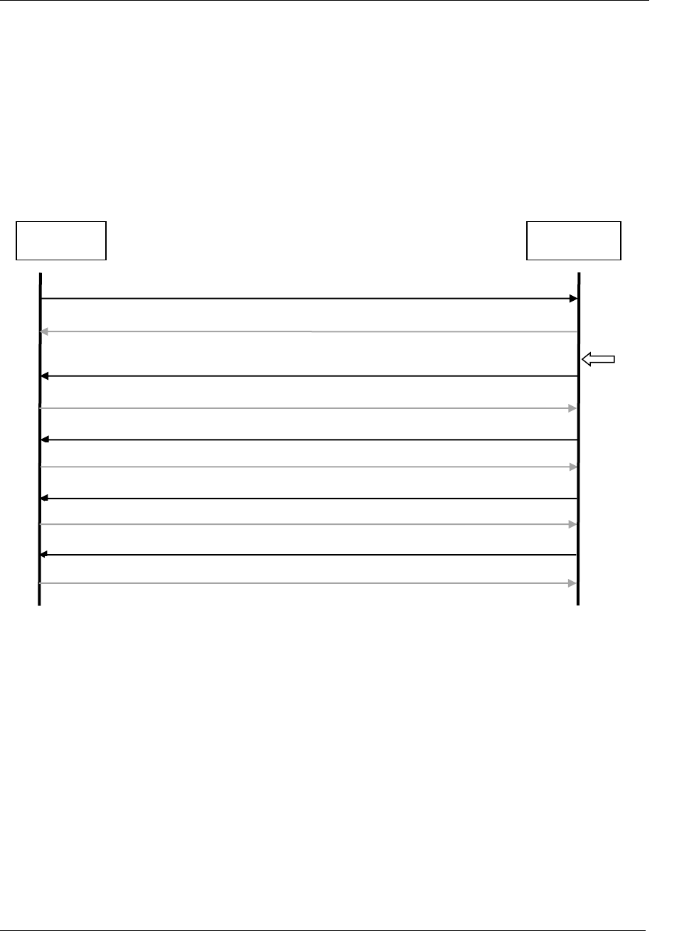
All messages
153 (285)
5.9 Application result messages with variables
These result data MIDs allow for step data to be sent, as well as most other available result variables.
MID 0005 Command accepted
Integrator
Controller
MID0008, Subscription of MID 1201, latest and new data, send object
result=true
Tightening
done,
3 spindles
MID1201, Operation result Overall data
MID1202, Operation result Object data
MID 1203 Last operation result data acknowledge
MID 1203 Last operation result data acknowledge
MID1202, Operation result Object data
MID 1203 Last operation result data acknowledge
MID1202, Operation result Object data
MID 1203 Last operation result data acknowledge

All messages
154 (285)
5.9.1 MID 1201 Operation result Overall data
This MID contains the overall result data and some of the object data of the last tightening. In the
subscription of this message it can be chosen to also start subscription of MID 1202 Operation result
object data. The user defined values is preconfigured in the controller via the configuration tool.
Message sent by: Controller
Answer:
MID 1203 Operation result data acknowledge or MID 0005 with MID 1201 in the data field.
If the sequence number acknowledge functionality is used there is no need for these
acknowledges.
5.9.1.1 Subscription, MID 1201
Use MID 0008 to start subscription, Table 92 shows the content in the “Extra data” field.
Table 92 MID 1201, Subscription “Extra data” field included in MID 0008, rev 001.
Parameter
Size
[byte]
Data
type
Description
Send
alternatives
1
UI
Following alternatives are available.
One ASCII digit 0=Only new data, 1= Stored data from given index, 2 Stored data
from given time stamp, 3 Stored data between two indexes, 4 Stored data
between two given time stamps in Unix time ( Seconds since 1970-01-01)..
If = 0 then only the last data stored and data stored after that the subscription is
done is sent to the subscriber. Old unsent data will not be sent to the subscriber.
If = 1 the data from given INDEX is sent inclusive the latest stored.
If = 2 the data from given time stamp in Unix format is sent inclusive the latest
stored.
If = 3 the data between two given indexes is sent
If = 4 the data between two given time stamps in Unix time is sent
STRUCTURE FOR ALTERNATIVE 0-2
Data Identifier
Time Stamp
type
19
T
The identifier is a Time stamp of the requested data.
The first data sent will be the first data and inclusive this time stamp and forward
up to and inclusive the last one.
If the data is not found, rewind will be to oldest possible data.
All data from this point up to the newest available will be sent directly on
subscribe.
If not used filled in with zeroes e.g at alternative 1.
At alternative 2 it contains the Time Stamp ex. 2015.10.01:19:01:30.
Data Identifier
Index type or
unix time type
10
UI
The Identifier INDEX or the UNIX time (at Alternative 2) of the data to rewind to.
10 bytes. Only used for old stored process data.
The first data sent will be the data from and inclusive this point and forward up to
and inclusive the last one.
If the data is not found, or if the value is 0, rewind will be to oldest possible data.
All data from this point up to the newest available will be sent directly on subscribe.
Send object
data
1
B
Start subscription of MID 1202. It is not possible to only start subscription of MID
1202 without a subscription of MID 1201.
STRUCTURE FOR ALTERNATIVE 3

All messages
155 (285)
Data Identifier
First index
10
UI
The first identifier is an index result id.
The first data sent will be the first data, this index included.
If the data is not found, there will be reported error.
All data from this point up to the last given index will be sent directly on subscribe
if found, else error.
Data Identifier
Last Index
10
UI
The second Identifier is an index result id.
Send object
data
1
B
Start subscription of MID 1202. It is not possible to only start subscription of MID
1202 without a subscription of MID 1201.
STRUCTURE FOR ALTERNATIVE 4
Data Identifier
First Unix time
10
UI
The first identifier is an Unix time = Seconds since 1970-01-01.
The first data sent will be the first data after this time.
If the data is not found, there will be reported error.
All data from this point up to the second given time will be sent directly on
subscribe if found, else error.
Data Identifier
Last Unix time
10
UI
The second Identifier is a Unix time.
Send object
data
1
B
Start subscription of MID 1202. It is not possible to only start subscription of MID
1202 without a subscription of MID 1201.
Message sent by: Integrator
Answer: MID 0005 Command accepted with MID 1201 in the data field or
MID 0004 Command error with MID 1201 in the data field with error code, Subscription on specific data not
supported or Invalid data.
After a MID 0005 the last stored data is sent from the Controller to the Integrator in addition.
5.9.1.2 Un subscription, MID 1201
Use MID 0009 to unsubscribe. No “Extra data” field is needed.

All messages
156 (285)
5.9.1.3 Data field, MID 1201
Table 93 MID 1201 Data, revision 1
Parameter
Size
[byte]
Data
type
Description
Total no of messages
3
UI
The total number of messages needed to send all data for all
tools/screws in the tightening. The rest of the messages are of type
MID 1202 Operation result object data, one message for each object.
Message number
3
UI
This parameter is always 001 as this is the first message.
Result Data Identifier
10
UI
The Result Data Identifier is a unique ID for each operation result
within the system.
Time
19
T
Cycle start time for each operation sent to the control station. The time
is 19 byte long and is specified by 19 ASCII characters (YYYY-MM-
DD:HH:MM:SS)
Result status
1
UI
The total status of the operation. One byte long and is specified by
one ASCII digit (‘0’ or ‘1’).
0=cycle NOK, 1=cycle OK.
Operation type
2
UI
Operation type:
0=Non synchronized tightening, i.e. a hand tool
1=Synchronized tightening, i.e. a fixture multiple
2=Pressing
3=Drilling
4=Pulse
Number of objects
3
UI
The total number of objects in the operation
The object part in this message is repeated Number of objects times.
Object data
Number
of objects
* 5
Parameter
Size
[byte]
Data
type
Description
Object Id
4
UI
The user defined Object Id.
Object Status
1
UI
Specified by one ASCII digit.
0=NOK, 1=OK
Number of data fields
3
UI
The number of variable data fields in the telegram. If no data fields
exist “000” will be sent.
Data fields
Vary
This section is repeated Number of data fields times. If Number of
data fields = 000, this section is not sent. The structure is of variable
parameter type see Variable Data Field Use
Note: It is NOT allowed to use the ‘Data values’ fields of this telegram to send data that are spindle/bolt/controller
specific. If ANY data of this type is wanted the telegram 1202 MUST be used instead. If spindle/bolt/controller specific
data is sent in 1201 the telegram will not be compatible between single and multiple tightenings and this is not good.
Also there is a mandatory to include variable data fields of parameters for the oldest and the last INDEX and the oldest
and the last TIME STAMPs. See specific controller documents.

All messages
157 (285)
5.9.2 MID 1202 Operation result object data
This message contains the cycle data for one object, both data for the whole process and data related to
the different steps in the process. The user defined values are preconfigured in the controller via the
configuration tool. The message uses the Variable Parameter pattern for transmission of the values.
Note: Only values that exist in the result will be sent. So the actual data received may vary between
the cycles if the settings differ between different programs.
Message sent by: Controller
Answer:
MID 1203 Operation result data acknowledge or MID 0005 with MID 1202 in the data field.
If the sequence number acknowledge functionality is used there is no need for these
acknowledges.
5.9.2.1 Subscription, on MID1202
Start subscription of MID1201 and set the “Send object data”=TRUE.
5.9.2.2 Unsubscribe, on MID1202
To unsubscribe on this mid you need to unsubscribe on MID 1201.
5.9.2.3 Data field, MID 1202
Table 94 MID 1202, revision 1
Parameter
Size
[byte]
Data
type
Value
Total no of
messages
3
UI
The total number of messages needed to send all object data for all objects,
including message MID 1201 Last operation result Overall data, sent with the
station data. One message MID 1202 Last operation result Object data is sent for
each Bolt.
Message
number
3
UI
This number counts from 002 to Total no of messages and is incremented by 1 for
each sent message.
The first Bolt message is message number 002, since MID 1201 Operation result
Overall data is number 001.
3 ASCII digits, range 002-999.
Result Data
Identifier
10
UI
The Result Data Identifier is a unique ID for each object result within the system.
Will always match the Result identifier sent in MID 1201 Last operation result
Overall data.
Object Id
4
UI
The user defined Object Id.
Number of
data fields
3
UI
The number of variable data fields in the telegram. Format: ASCII digits.
If no values exist “000” will be sent.
Data fields
Vary
This section is repeated Number of data fields times. If Number of data fields = 000,
this section is not sent. The structure is of variable parameter type see Variable
Data Field Use

All messages
158 (285)
5.9.3 MID 1203 Operation result data acknowledge
Message sent by: Integrator
Answer: None
Only Header is sent with no data fields.
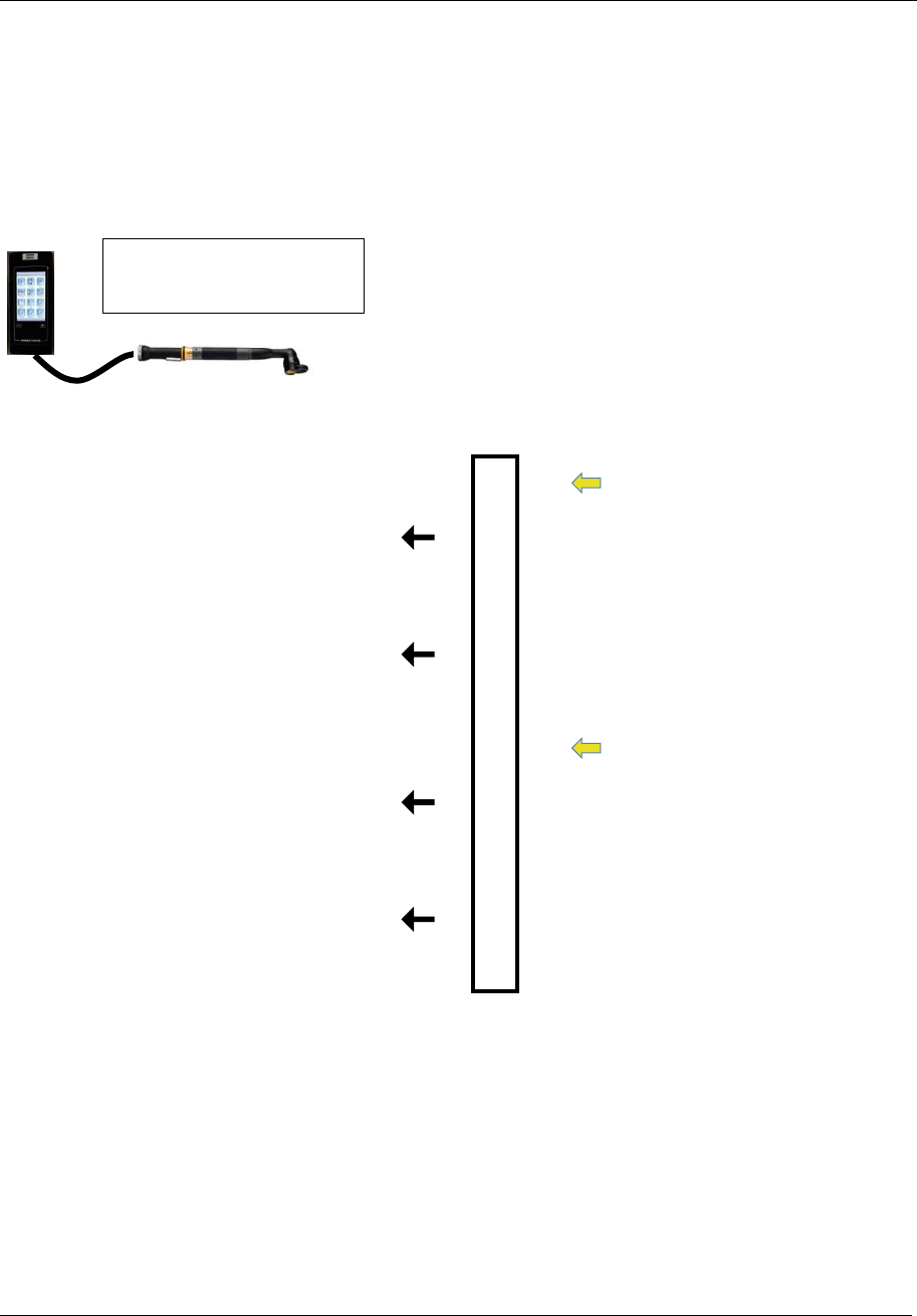
All messages
159 (285)
5.9.4 Examples
All the examples below assume a subscription on MID 1201 Operation result Overall data has first
been made. In the subscription it is assumed Send object data is set.
Hand tool
Telegrams sent
Controller
Tightening done with PSet 1
MID 1201 Operation result Overall data
Total no of messages = 2
Message number = 1
Number of objects = 1
MID 1202 Operation result Object data
Total no of messages = 2
Message number = 2
Tightening done with PSet 2
MID 1201 Operation result Overall data
Total no of messages = 2
Message number = 1
Number of objects = 1
MID 1202 Operation result Object data
Total no of messages = 2
Message number = 2
Running:
PSet 1 and when PSet 2
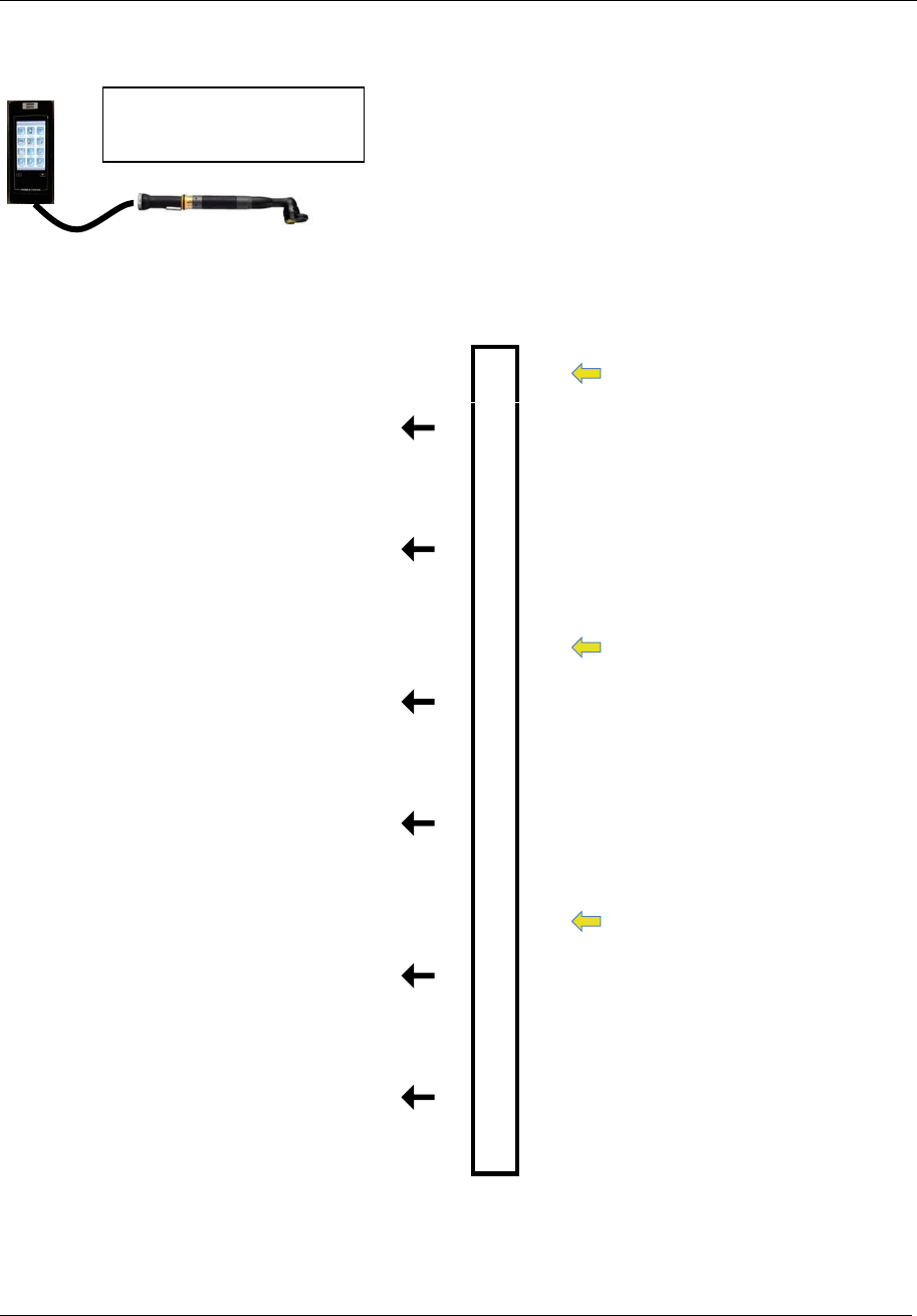
All messages
160 (285)
Hand tool running batch
Telegrams sent
Controller
Tightening done with PSet 4
MID 1201 Operation result Overall data
Total no of messages = 2
Message number = 1
Number of objects = 1
MID 1202 Operation result Object data
Total no of messages = 2
Message number = 2
Tightening done with PSet 4
MID 1201 Operation result Overall data
Total no of messages = 2
Message number = 1
Number of objects = 1
MID 1202 Operation result Object data
Total no of messages = 2
Message number = 2
Tightening done with PSet 4
MID 1201Operation result Overall data
Total no of messages = 2
Message number = 1
Number of objects = 1
MID 1202 Operation result Object data
Total no of messages = 2
Message number = 2
Running:
PSet 4 three times
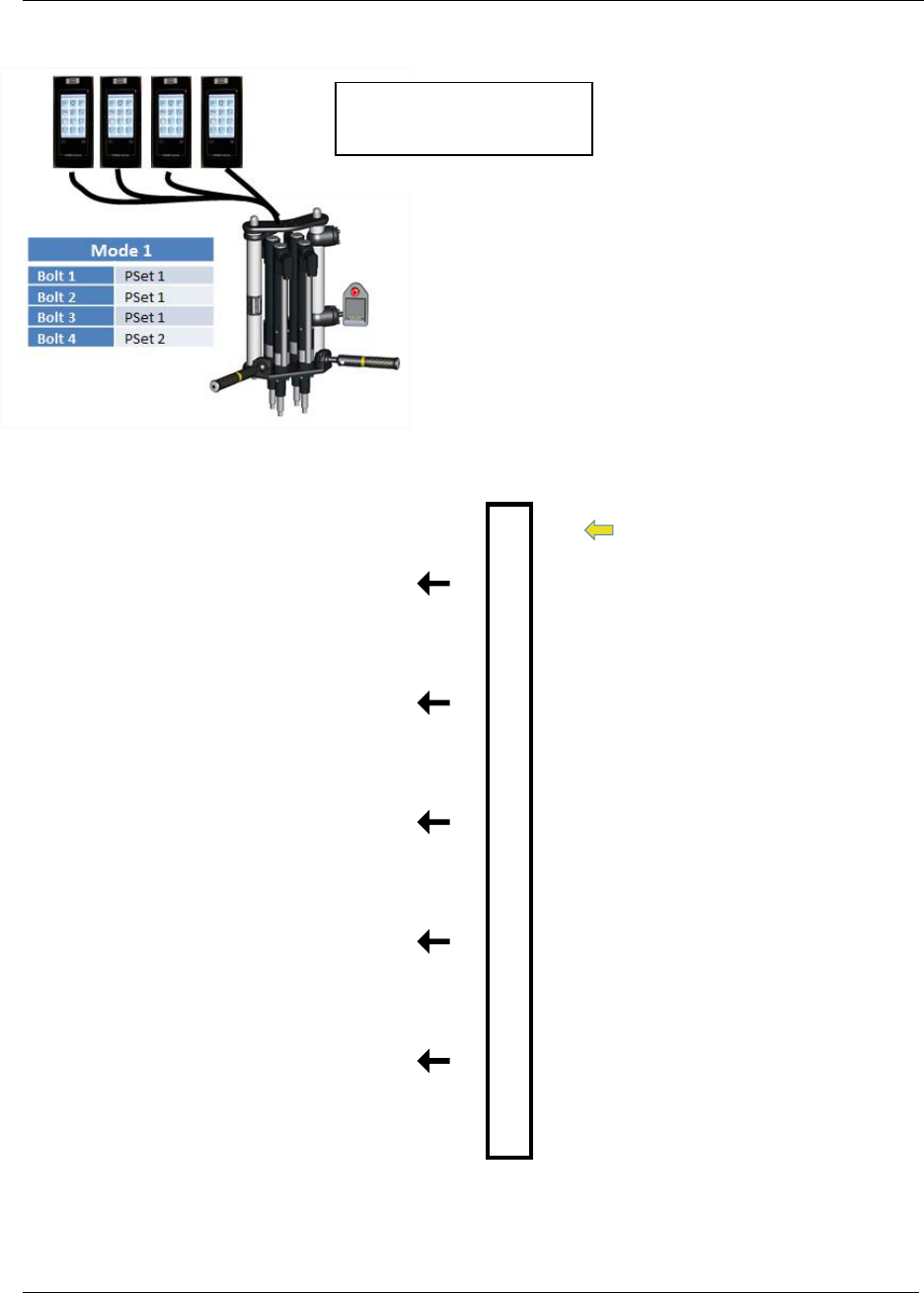
All messages
161 (285)
Multiple with 4 spindles
Telegrams sent
Controller
Tightening done with Mode 1
MID 1201 Operation result Overall data
Total no of messages = 5
Message number = 1
Number of objects = 4
MID 1202 Operation result Object data
Total no of messages = 5
Message number = 2
Object Id = 0001
MID 1202 Operation result Object data
Total no of messages = 5
Message number = 3
Object Id = 0002
MID 1202 Operation result Object data
Total no of messages = 5
Message number = 4
Object Id = 0003
MID 1202 Operation result Object data
Total no of messages = 5
Message number = 5
Object Id = 0004
Running:
Mode 1

All messages
162 (285)
Multiple with 2 spindles running batch
Telegrams sent
Controller
Tightening done with Mode 3
MID 1201 Operation result Overall data
Total no of messages = 3
Message number = 1
Number of objects = 2
MID 1202 Operation result Object data
Total no of messages = 3
Message number = 2
Object Id = 0001
MID 1202 Operation result Object data
Total no of messages = 3
Message number = 3
Object Id = 0002
Running:
Mode 3 two times

All messages
163 (285)
5.10 Application Alarm messages
5.10.1 MID 0070 Alarm subscribe
A subscription for the alarms that can appear in the controller.
Message sent by: Integrator
Answer: MID 0005 Command accepted or
MID 0004 Command error, Alarm subscription already exists
For header description see section 2.2.2!
5.10.2 MID 0071 Alarm
An alarm has appeared in the controller. The current alarm is uploaded from the controller to the
integrator.
Message sent by: Controller
Answer: MID 0072 Alarm acknowledge
Example: MID 0071. Alarm E404 appeared on June 12, 2008. The controller and the tool have ready
status.
00530071 01E404021031042008-06-02:10:14:26NUL
For header description see section 2.2.2!
Table 95 MID 0071 Alarm data revision 0-1
Parameter
Byte
Value
Error code
21-22
01
23-26
The error code is specified by 4 ASCII characters.
Example E851 or 1010.
Controller ready status
27-28
02
29
Controller ready status 1=OK, 0=NOK
Tool ready status
30-31
03
32
Tool ready status 1=OK, 0=NOK
Time
33-34
04
35-53
Time stamp for the alarm. 19 ASCII characters.
YYYY-MM-DD:HH:MM:SS
Table 96 MID 0071 Alarm data revision 2

All messages
164 (285)
Parameter
Byte
Value
Error code
21-22
01
23-27
The error code is specified by 5 ASCII characters.
But doesn’t have to be five characters long, not used
characters are replaced with space or according to
application specific appendix. Example E1021.
Controller ready status
28-29
02
30
Controller ready status 1=OK, 0=NOK
Tool ready status
31-32
03
33
Tool ready status 1=OK, 0=NOK
Time
34-35
04
36-54
Time stamp for the alarm. 19 ASCII characters.
YYYY-MM-DD:HH:MM:SS
Alarm text
55-56
05
57-107
Alarm text. 50 ASCII characters

All messages
165 (285)
5.10.3 MID 0072 Alarm acknowledge
Acknowledgement for MID 0071 Alarm.
Message sent by: Integrator
Answer: None
For header description see section 2.2.2!
5.10.4 MID 0073 Alarm unsubscribe
Reset the subscription for the controller alarms.
Message sent by: Integrator
Answer: MID 0005 Command accepted or
MID 0004 Command error, Alarm subscription does not exist
For header description see section 2.2.2!

All messages
166 (285)
5.10.5 MID 0074 Alarm acknowledged on controller
The message is sent by the controller to inform the integrator that the current alarm has been
acknowledged.
Message sent by: Controller
Answer: MID 0075 Alarm acknowledged on controller acknowledge
Example: MID 0074 Alarm E406 acknowledged on controller.
00240074 E406NUL
For header description see section 2.2.2!
Table 97 MID 0074 Revision 1
Parameter
Byte
Value
Error code
21-24
Four ASCII characters
5.10.6
5.10.6 MID 0075 Alarm acknowledged on controller acknowledge
Acknowledgement of MID 0074 Alarm acknowledged on controller.
Message sent by: Integrator
Answer: None
For header description see section 2.2.2!
5.10.7 MID 0076 Alarm status
The alarm status is sent after an accepted subscription of the controller alarms. This message is used to
inform the integrator that an alarm is active on the controller at subscription time.
Message sent by: Controller
Answer: MID 0077 Alarm status acknowledge
Example: MID 0076. Alarm E404 is active, the controller and the tool are ready.
00560076 01102E404031041052008-06-02:10:14:26NUL
For header description see section 2.2.2!
Table 98 MID 0076 Alarm status data Rev 1

All messages
167 (285)
Parameter
Byte
Value
Alarm status
21-22
01
23
0=no alarm is active, 1=an alarm is currently active
Error code
24-25
02
26-29
The error code is specified by 4 ASCII characters. Example E851
or 1010.
Controller ready status
30-31
03
32
Controller ready status 1=OK, 0=NOK
Tool ready status
33-34
04
35
Tool ready status 1=OK, 0=NOK
Time
36-37
05
38-56
Time stamp for the alarm. 19 ASCII characters.
YYYY-MM-DD:HH:MM:SS
Table 99 MID 0076 Alarm status data Rev 2
Parameter
Byte
Value
Alarm status
21-22
01
23
0=no alarm is active, 1=an alarm is currently active
Error code
24-25
02
26-30
The error code is specified by 5 ASCII characters. But doesn’t
have to be five characters long, not used characters are replaced
with space or according to application specific appendix. Example
E1021.
Controller ready status
31-32
03
33
Controller ready status 1=OK, 0=NOK
Tool ready status
34-35
04
36
Tool ready status 1=OK, 0=NOK
Time
37-38
05
39-57
Time stamp for the alarm. 19 ASCII characters.
YYYY-MM-DD:HH:MM:SS
5.10.8 MID 0077 Alarm status acknowledge
Acknowledgement of MID 0076 Alarm Status.
Message sent by: Integrator
Answer: None
For header description see section 2.2.2!

All messages
168 (285)
5.10.9 MID 0078 Acknowledge alarm remotely on controller
The integrator can remotely acknowledge the current alarm on the controller by sending MID 0078. If
no alarm is currently active when the controller receives the command, the command will be rejected.
Message sent by: Integrator
Answer: MID 0005 Command accepted or
MID 0004 Command error, No alarm present or
Invalid data
For header description see section 2.2.2!

All messages
169 (285)
5.11 Application Time messages
5.11.1 MID 0080 Read time upload request
Read time request.
Message sent by: Integrator
Answer: MID 0081 Read time upload reply
For header description see section 2.2.2!
5.11.2 MID 0081 Read time upload reply
Time upload reply from the controller.
Message sent by: Controller
Answer: None
For header description see section 2.2.2!
Table 100 MID 0081 Revision 1
Parameter
Byte
Value
Time
21-39
19 ASCII characters: YYYY-MM-DD:HH:MM:SS
5.11.3 MID 0082 Set Time
Set the time in the controller.
Message sent by: Integrator
Answer: MID 0005 Command accepted
For header description see section 2.2.2!
Table 101 MID 0082 Revision 1
Parameter
Byte
Value
Time
21-39
19 ASCII characters: YYYY-MM-DD:HH:MM:SS

All messages
170 (285)
5.12 Application Multi-spindle status messages
The multi-spindle messages for Power Focus are always exchanged with a sync Master. For
PowerMACS, these messages are exchanged with the station using the IP address of the station TC.
5.12.1 MID 0090 Multi-spindle status subscribe
A subscription for the multi-spindle status. For Power Focus, the subscription must be addressed to the
sync Master.
Message sent by: Integrator
Answer: MID 0005 Command accepted or
MID 0004 Command error, Controller is not a sync master/station controller, or
Multi-spindle status subscription already exists
For header description see section 2.2.2!
5.12.2 MID 0091 Multi-spindle status
The multi-spindle status is sent after each sync tightening. The multiple status contains the common
status of the multiple as well as the individual status of each spindle.
Message sent by: Controller
Answer: MID 0092 Multi-spindle status acknowledge
Example: Multiple status for two spindles. Common status OK, spindle 1 OK, spindle 2 OK.
00670091 01020200012032001-06-02:10:14:26 041050120102041NUL
For header description see section 2.2.2!
Table 102 MID 0091 Multi-spindle status data
Parameter
Byte
Value
Number of spindles
21-22
01
23-24
Number of spindles running in the multiple. The number of spindles is two
bytes long and specified by 2 ASCII digits, range 02-10.
Sync tightening ID
25-26
02
27-31
The sync tightening ID is a unique ID for each sync tightening result.
Each individual result of each spindle is stamped with this ID.
The tightening ID is incremented after each sync tightening. It is specified
by five ASCII digits. Range: 00000-65535.
Time
32-33
03
34-52
Time stamp. 19 ASCII characters. YYYY-MM-DD:HH:MM:SS

All messages
171 (285)
Sync overall status
33-54
04
35
The status of all the spindles. OK if the individual status of each spindle is
OK, NOK if at least one spindles status is NOK. One ASCII digit 1=OK,
0=NOK.
Spindle status
36-37
05
38-
5 number of spindles.
Bytes 1-2: The first two bytes specify the spindle number in the same order
as in the sync list. Range 01-99.
Bytes 3-4: The next two bytes are the channel ID of the spindle. Range 01-
20
Byte 5: The fifth byte is the individual overall status of the tightening of
each spindle 0=NOK, 1=OK

All messages
172 (285)
5.12.3 MID 0092 Multi-spindle status acknowledge
Multi-spindle status acknowledge.
Message sent by: Integrator
Answer: None
For header description see section 2.2.2!
5.12.4 MID 0093 Multi-spindle status unsubscribe
Reset the subscription for the multi-spindle status.
Message sent by: Integrator
Answer: MID 0005 Command accepted or
MID 0004 Command error, Multi-spindle status subscription does not exist
For header description see section 2.2.2!
5.12.5 Application Multi-spindle result messages
The multi-spindle messages for Power Focus are always exchanged with a sync Master. For
PowerMACS, these messages are exchanged with the station using the IP address of the station TC.
5.12.6 MID 0100 Multi-spindle result subscribe
A subscription for the multi-spindle status. For Power Focus, the subscription must be addressed to a
sync Master.
This telegram is also used for a PowerMACS 4000 system running a press instead of a spindle. A
press system only supports revision 4 and higher of the telegram and will answer with MID 0004,
MID revision unsupported if a subscription is made with a lower revision.
Message sent by: Integrator
Answer: MID 0005 Command accepted or
MID 0004 Command error, Controller is not a sync master/station controller,
Multi-spindle result subscription already exists or MID revision unsupported
For header description see section 2.2.2!
(Revision 1 contains no data!)
Table 103 MID 0100 Revision 2
Parameter
Byte
Value
Data No. System
21-30
Data No System (see MID 0106) is the number for the cycle data
to rewind to. The first cycle data will be the cycle data after this

All messages
173 (285)
Parameter
Byte
Value
point.
If the data is not found, or if the value is 0, rewind will be to oldest
possible cycle data.
Table 104 MID 0100 Revision 3, 4 and 5
Parameter
Byte
Value
Send only new data
31
Send only new result data.
One ASCII digit 0=FALSE, 1=TRUE.
If TRUE then only the result data stored after that the subscription
is done is sent to the subscriber. Old result data of the unsent
result will not be sent to the subscriber.
This parameter has higher priorities than “Data No. System”. So if
this is TRUE, value in byte 21-30 is ignored and not preformed.
5.12.7 MID 0101 Multi-spindle result
The multi-spindle result is sent after each sync tightening and if it is subscribed. The multiple results
contain the common status of the multiple as well as the individual tightening result (torque and angle)
of each spindle.
This telegram is also used for PowerMACS systems running a Press. The layout of the telegram is
exactly the same but some of the fields have slightly different definitions. The fields for Torque are
used for Force values and the fields for Angle are used for Stroke values. A press system always uses
revision 4 or higher of the telegram.
Message sent by: Controller
Answer: MID 0102 Multi-spindle result acknowledge
For header description see section 2.2.2!
Table 105 MID 0101 Multi-spindle result data, Revision 1, 2 and 3
Parameter
Byte
Value
Number of
spindles
21-22
01
23-24
Number of spindles running in the multiple. The number of
spindles is two bytes long and specified by 2 ASCII digits,
range 01-50.
VIN Number
25-26
02
27-51
The VIN number is 25 bytes long and is specified by 25 ASCII
characters.
Job ID
52-53
03
54-55
The Job ID is two bytes long and specified by two ASCII digits.
Range: 00-99
Parameter set ID
56-57
04
58-60
The parameter set ID is three bytes long and specified by three
ASCII digits. Range: 000-999.
Batch size
61-62
05

All messages
174 (285)
Parameter
Byte
Value
63-66
This parameter gives the total number of tightening in the batch.
The batch size is four bytes long and specified by four ASCII
digits. Range: 0000-9999.
Batch counter
67-68
06
69-72
The batch counter information is four bytes long specifying and
specified by four ASCII digits. Range: 0000-9999.
Batch status
73-74
07
75
The batch status is specified by one ASCII character.
0=batch NOK (batch not completed), 1=batch OK,
2=batch not used.
Torque Min limit
76-77
08
78-83
The torque min limit in Nm is multiplied by 100 and sent as an
integer (2 decimals truncated). It is six bytes long and is
specified by six ASCII digits.
Torque Max limit
84-85
09
86-91
The torque max limit in Nm is multiplied by 100 and sent as an
integer (2 decimals truncated). It is six bytes long and is
specified by six ASCII digits.
Torque final target
92-93
10
94-99
The torque final target in Nm is multiplied by 100 and sent as an
integer (2 decimals truncated). It is six bytes long and is
specified by six ASCII digits.
Angle Min
100-101
11
102-106
The angle min value in degrees. Each turn represents 360
degrees. It is five bytes long and specified by five ASCII digits.
Range: 00000-99999.
Angle Max
107-108
12
109-113
The angle max value in degrees. Each turn represents 360
degrees. It is five bytes long and specified by five ASCII digits.
Range: 00000-99999.
Final Angle
Target
114-115
13
116-120
The target angle value in degrees. Each turn represents 360
degrees. It is five bytes long and specified by five ASCII digits.
Range: 00000-99999.
Date/time of last
change in
parameter set
settings
121-122
14
123-141
Time stamp for the last change in the current parameter set
settings. It is 19 bytes long and is specified by 19 ASCII
characters (YYYY-MM-DD:HH:MM:SS).
Time stamp
142-143
15
144-162
Time stamp. 19 ASCII characters
(YYYY-MM-DD:HH:MM:SS).
Sync tightening ID
163-164
16
165-169
The sync tightening ID is a unique ID for each sync tightening
result.
Each individual result of each spindle is stamped with this ID.
The tightening ID is incremented after each sync tightening. 5
ASCII digits, range 00000-65535.
Sync overall
170-171
17

All messages
175 (285)
Parameter
Byte
Value
status
172
The status of all the spindles. OK if the individual status of each
spindle is OK, NOK if at least one spindle status is NOK. One
ASCII digit 1=OK, 0=NOK.
Spindle status
173-174
18
175 -
175 + 18 x number
of spindles
18 number of spindles.
Bytes 1-2:
Spindle number in the same order as in the sync list. Range 01-
99.
Bytes 3-4:
Byte 5:
Individual overall status of the tightening of each spindle
0=NOK, 1=OK
Byte 6:
Individual torque status of each spindle. 0=Low, 1=OK, 2 =
High
Byte 7-12:
The torque result of each spindle. The torque in Nm is multiplied
by 100 and sent as an integer (2 decimals truncated). It is six
bytes long and specified by six ASCII digits.
Byte 13:
Individual angle status of each spindle. 0=NOK, 1=OK
Byte 14-18:
The turning angle value in degrees for each spindle. Each turn
represents 360 degrees. It is five bytes long and specified by
five ASCII digits. Range: 00000-99999.
Note: In a Power MACS system the unit used for torque measurement depends on the unit setting in the Power
MACS setup. If the setup use Nm that unit is used in the telegram and if the setup use FtLbs the telegrams also
use FtLbs.

All messages
176 (285)
Table 106 MID 0101 Multi-spindle result data, Revision 4
Parameter
Byte
Value
Number of spindles or
presses
21-22
01
23-24
Number of spindles or presses running in the multiple. The
number is two bytes long and specified by 2 ASCII digits,
range 01-50.
VIN Number
25-26
02
27-51
The VIN number is 25 bytes long and is specified by 25 ASCII
characters.
Job ID
52-53
03
54-55
The Job ID is two bytes long and specified by two ASCII digits.
Range: 00-99
Parameter set ID
56-57
04
58-60
The parameter set ID is three bytes long and specified by three
ASCII digits. Range: 000-999.
Batch size
61-62
05
63-66
This parameter gives the total number of cycles in the batch.
The batch size is four bytes long and specified by four ASCII
digits. Range: 0000-9999.
Batch counter
67-68
06
69-72
The batch counter information is four bytes long specifying and
specified by four ASCII digits. Range: 0000-9999.
Batch status
73-74
07
75
The batch status is specified by one ASCII character.
0=batch NOK (batch not completed), 1=batch OK,
2=batch not used.
Torque or Force Min
limit
76-77
08
78-83
The torque or force min limit, see description of torque and force
values below.
Torque or Force Max
limit
84-85
09
86-91
The torque or force max limit, see description of torque and
force values below.
Torque of Force final
target
92-93
10
94-99
The torque or force final target, see description of torque and
force values below.
Angle or Stroke Min
limit
100-101
11
102-106
Angle or stroke min limit, see description of angle and stroke
values below.
Angle or Stroke Max
limit
107-108
12
109-113
The angle or stroke max limit, see description of angle and
stroke values below.
Final Angle or Stroke
Target
114-115
13
116-120
The target angle or stroke value, see description of angle and
stroke values below..
Date/time of last
change in parameter
set settings
121-122
14
123-141
Time stamp for the last change in the current parameter set
settings. It is 19 bytes long and is specified by 19 ASCII
characters (YYYY-MM-DD:HH:MM:SS).

All messages
177 (285)
Parameter
Byte
Value
Time stamp
142-143
15
144-162
Time stamp. 19 ASCII characters
(YYYY-MM-DD:HH:MM:SS).
Sync tightening ID
163-164
16
165-169
The identity is a unique ID for each sync result.
Each individual result of each spindle or press is stamped with
this ID.
The ID is incremented after each sync cycle. 5 ASCII digits,
range 00000-65535.
Sync overall status
170-171
17
172
The status of all the spindles or presses. OK if the individual
status of each spindle or press is OK, NOK if at least one of
them has status NOK. One ASCII digit 1=OK, 0=NOK.
Spindle or Press status
173-174
18
175 -
175 + 18 x
number of
spindles
18 number of spindles or presses
Bytes 1-2:
Spindle or press number in the same order as in the sync list.
Range 01-99.
Bytes 3-4:
Channel ID of the spindle or press. Range 01-99
Byte 5:
Individual overall status of the cycle of each spindle or press.
0=NOK, 1=OK
Byte 6:
Individual torque or force status of each spindle or press.
0=NOK, 1=OK
Byte 7-12:
The torque or force result of each spindle or press, see
description of torque and force values below.
Byte 13:
Individual angle or stroke status of each spindle or press.
0=NOK, 1=OK
Byte 14-18:
The measured angle or stroke value for each spindle or press,
see description of angle and stroke values below.
System sub type
+2
19
+3
The subtype of the system sending the data. 3 ASCII digits.
Have the same value as the field System subtype in MID 0002
Communication start acknowledge.
For a PowerMACS 4000 system it can have the following
values:
001 = a normal tightening system
002 = a system running presses instead of spindles. If the
system subtype is 002 for Press all the data above is Force and
Stroke instead of Torque and Angle

All messages
178 (285)
Table 107 MID 0101 Multi-spindle result data, Revision 5
Job sequence number
+2
20
+5
The Job sequence number is unique for each Job. All
tightenings performed in the same Job are stamped with the
same Job sequence number. It is specified by five ASCII digits.
Range: 00000-65535. When unused should be: 00000
Angle values:
Sent with unit degrees. Each turn represents 360 degrees. It is five bytes long and specified by five
ASCII digits. Range: 00000-99999.
Stroke values:
Sent with unit mm. The value is multiplied by 100 and sent as an integer (2 decimals truncated). It is
five bytes long and is specified by five ASCII digits. Range -99.99 – +999.99 mm sent as -9999 –
99999.
Torque values:
The torque is multiplied by 100 and sent as an integer (2 decimals truncated). It is six bytes long and is
specified by six ASCII digits. The unit is Nm.
Force values:
The force is multiplied by 100 and sent as an integer (2 decimals truncated). It is six bytes long and is
specified by six ASCII digits. The unit is kN.
Note: In revision 4 of the telegram a PowerMACS system always use Nm for the torque measurement,
independent of the setting in the PowerMACS setup. The unit of force measurements in a press system
is always kN.

All messages
179 (285)
5.12.8 MID 0102 Multi-spindle result acknowledge
Multi-spindle result acknowledge.
Message sent by: Integrator
Answer: None
For header description see section 2.2.2!
5.12.9 MID 0103 Multi spindle result unsubscribe
Reset the subscription for the multi spindle result.
Message sent by: Integrator
Answer: MID 0005 Command accepted or
MID 0004 Command error, Multi spindle result subscription does not exist
For header description see section 2.2.2!

All messages
180 (285)
5.13 Application PowerMACS result data
The PowerMACS result data MIDs allow for step data to be sent, as well as most other available
PowerMACS result variables. The intention is also that it should be easy to add any new result
variables without having to change the protocol specification.
The variables that are sent with Open Protocol are selected in the reporter in PowerMACS. The data
needed for the station messages and for the header part of the Bolt messages are always selected. For
most of the remaining data is possible to select if it should be sent or not. All data is listed in the
Appendix PowerMACS data, names for variable identification
The fields Width and Decimals in the reporter are not accessible; the data is always formatted
according to the message specifications.
5.13.1 MID 0105 Last PowerMACS tightening result data
subscribe
Set the subscription for the rundowns result. The result of this command will be the transmission of
the rundown result after the tightening is performed (push function).
This telegram is also used for a PowerMACS 4000 system running a press instead of a spindle. A
press system only supports revision 4 and higher of the telegram and will answer with MID 0004,
MID revision unsupported if a subscription is made with a lower revision.
Message sent by: Integrator
Answer: MID 0005 Command accepted or
MID 0004 Command error, Subscription already exists or MID revision
unsupported
For header description see section 2.2.2!
(OBS! Revision 1 contains no data!)

All messages
181 (285)
Table 108 MID 0105 Revision 2, 3 and 4
Parameter
Revision
Byte
Value
Data No System
2-3
21-30
Data No System (see MID 0106) is the system number of the
cycle data to rewind to.
Two ASCII digits 00.
The first cycle data will be the cycle data after this point.
If the data is not found, or if the value is 0, rewind will be to oldest
possible cycle data.
Send only new data
3
31
Send only new result data.
One ASCII digit 0=FALSE, 1=TRUE.
If TRUE then only the result data stored after that the subscription
is done is sent to the subscriber. Old result data of the unsent
result will not be sent to the subscriber.
This parameter has higher priorities than “Data No System”. So if
this is TRUE, value in byte 21-30 is ignored and not preformed.
5.13.2 MID 0106 Last PowerMACS tightening result Station data
This MID contains the station part and some of the Bolt data of the last result data. After this message
has been sent the integrator selects if it also wants to have the Bolt and step data. If this data is
requested, then the integrator sends the message MID 0108 Last PowerMACS tightening result data
acknowledge, with the parameter Bolt Data set to TRUE. If only the station data is wanted the
parameter Bolt Data is set to FALSE.
This telegram is also used for Power MACS systems running a Press. The layout of the telegram is
exactly the same but some of the fields have slightly different definitions. The fields for Torque are
used for Force values and the fields for Angle are used for Stroke values. Press systems also use
different identifiers for the optional data on bolt and step level. A press system always use revision 4
or higher of the telegram
Note: All values that are undefined in the results will be sent as all spaces (ASCII 0x20). This will for
instance happen with the Torque Status if no measuring value for Bolt T was available for the
tightening.
Message sent by: Controller
Answer: MID 0108 Last Power MACS tightening result data acknowledge
For header description see section 2.2.2!
Table 109 MID 0106 Last tightening result Station data, revision 1,2 and 3
Parameter
Byte
Value
Total no of messages
21-22
01
23-24
The total number of messages needed to send all Bolt data for all
Bolts. The rest of the messages are of type MID 0107 Last
PowerMACS tightening result Bolt data, once for each Bolt.
They are only sent on request from the integrator. 2 ASCII digits,
range 00-99.
Message number
25-26
02
27-28
This parameter is always 01 as this is the first message.

All messages
182 (285)
Parameter
Byte
Value
Data No System
29-30
03
31-40
The Data No system is a unique ID for each tightening result
within the system. 10 ASCII digits, max value are 4294967295.
Station No
41-42
04
43-44
The station number within the PowerMACS system. 2 ASCII
digits, range 01-15.
Station Name
45-46
05
47-66
The station name is 20 bytes long and is specified by 20 ASCII
characters.
Time
67-68
06
69-87
Cycle start time for each tightening sent to the control station. The
time is 19 byte long and is specified by 19 ASCII characters
(YYYY-MM-DD:HH:MM:SS)
Mode No
88-89
07
90-91
The mode number used for the tightening. 2 ASCII digits, range
01-50. If undefined, empty spaces are sent.
Mode Name
92-93
08
94-113
The name of the mode used for the tightening. Specified by 20
ASCII characters. If undefined, empty spaces are sent.
Simple status
114-115
09
116
One byte long and is specified by one ASCII digit (‘0’ or ‘1’).
0=tightening NOK, 1=tightening OK.
PM Status
117-118
10
119
The status of the tightening, specified by one ASCII digit.
0=OK, 1=OKR, 2=NOK, 3=TERMNOK.
Wp. Id
120-121
11
122-161
The Wp. Id is 40 bytes long and is specified by 40 ASCII
characters. If undefined, empty spaces are sent.
Number of Bolts
162-163
12
164-165
The total number of Bolts in the tightening, 2 ASCII digits.
The Bolt part in this message (indicated with double table border)
is repeated Number of Bolt times. The parameter numbers (13-
22) are also repeated.

All messages
183 (285)
Parameter
Byte
Value
Ordinal Bolt Number
+2
13
+2
The ordinal Bolt number, the Bolts in the station are always
numbered from 01 to 50. 2 ASCII digits.
Simple Bolt Status
+2
14
+1
Specified by one ASCII digit (‘0’ or ‘1’). 0=tightening NOK,
1=tightening OK.
Torque Status
+2
15
+1
Torque status of each Bolt, specified by one ASCII digit
0=Bolt T Low
1=Bolt T OK
2=Bolt T High
If undefined, empty spaces are sent.
Angle Status
+2
16
+1
Angle status of each Bolt, specified by one ASCII digit
0=Bolt A Low
1=Bolt A OK
2=Bolt A High
If undefined, empty spaces are sent.
Bolt T
+2
17
+7
Sent as 7 ASCII digits formatted as a float.
The value is sent with 4 decimal places, for example 99.9999 or
-9.9999. If the value is larger than 99 the needed number of
decimals are removed to fit the integer part, i.e. 12345.123 is sent
as “12345.1”.
The unit is Nm. If undefined, empty spaces are sent.
Bolt A
+2
18
+7
Sent as 7 ASCII digits, formatted as a float, see description for
Bolt T.
The unit is degrees. If undefined, empty spaces are sent.
Bolt T High Limit
+2
19
+7
Sent as 7 ASCII digits, formatted as a float, see description for
Bolt T. The unit is Nm. If undefined, empty spaces are sent.
Bolt T Low Limit
+2
20
+7
Sent as 7 ASCII digits, formatted as a float, see description for
Bolt T. The unit is Nm. If undefined, empty spaces are sent.
Bolt A High Limit
+2
21
+7
Sent as 7 ASCII digits, formatted as a float, see description for
Bolt T.
The unit is degrees. If undefined, empty spaces are sent.
Bolt A Low Limit
+2
22
+7
Sent as 7 ASCII digits, formatted as a float, see description for
Bolt T. The unit is degrees. If undefined, empty spaces are sent.

All messages
184 (285)
Parameter
Byte
Value
Number of special values
+2
23
+2
The total number of special values sent in this message. Range
00-99.
+ n x
number
of
special
values
This section is repeated Number of special values times. If
Number of special values=00, this section is not sent.
Byte 1-20:
Variable name. 20 ASCII characters
Byte 21-22:
Type: 2 ASCII characters.
Byte 23-34:
Length: 2 ASCII digits.
Byte 25- :
Value: The value of the variable. The format and
length depend on the parameters Type and Length.
Note 1: All fields with strings are left adjusted and padded with spaces. All numerical fields are right
adjusted and padded with 0’s.
Note 2: In revision 1, 2 and 3 of the telegram the unit used for torque measurement depends on the
unit setting in the PowerMACS setup. If the setup use Nm that unit is used in the telegram and if the
setup use FtLbs the telegrams also use FtLbs.
Table 110 MID 0106 Last tightening result Station data, revision 4
Parameter
Byte
Value
Total no of messages
21-22
01
23-24
The total number of messages needed to send all Bolt (object)
data for all Bolts. The rest of the messages are of type MID 0107
Last PowerMACS tightening result Bolt data, once for each
Bolt. They are only sent on request from the integrator. 2 ASCII
digits, range 00-99.
Message number
25-26
02
27-28
This parameter is always 01 as this is the first message.
Data No System
29-30
03
31-40
The Data No system is a unique ID for each result within the
system. 10 ASCII digits, max value are 4294967295.
Station No
41-42
04
43-44
The station number within the PowerMACS system. 2 ASCII
digits, range 01-15.
Station Name
45-46
05
47-66
The station name is 20 bytes long and is specified by 20 ASCII
characters.
Time
67-68
06
69-87
Cycle start time for each cycle sent to the control station. The time
is 19 byte long and is specified by 19 ASCII characters (YYYY-
MM-DD:HH:MM:SS)
Mode No
88-89
07
90-91
The mode number used for the cycle. 2 ASCII digits, range 01-50.
If undefined, empty spaces are sent.
Mode Name
92-93
08

All messages
185 (285)
Parameter
Byte
Value
94-113
The name of the mode used for the cycle. Specified by 20 ASCII
characters. If undefined, empty spaces are sent.
Simple status
114-115
09
116
One byte long and is specified by one ASCII digit (‘0’ or ‘1’).
0=cycle NOK, 1=cycle OK.
PM Status
117-118
10
119
The status of the tightening (pressing), specified by one ASCII
digit.
0=OK, 1=OKR, 2=NOK, 3=TERMNOK.
Wp. Id
120-121
11
122-161
The Wp. Id is 40 bytes long and is specified by 40 ASCII
characters. If undefined, empty spaces are sent.
Number of Bolts or Objects
162-163
12
164-165
The total number of Bolts or Objects in the tightening, 2 ASCII
digits.
The Bolt/Object part in this message (indicated with double table
border) is repeated Number of Bolt times. The parameter
numbers (13-22) are also repeated.

All messages
186 (285)
Parameter
Byte
Value
Ordinal Bolt or Object
Number
+2
13
+2
The ordinal Bolt (object) number, the Bolts in the station are
always numbered from 01 to 50. 2 ASCII digits.
Simple Bolt or Object Status
+2
14
+1
Specified by one ASCII digit (‘0’ or ‘1’). 0=cycle NOK, 1=cycle OK.
Torque or Force Status
+2
15
+1
Torque or force status of each Bolt or Object, specified by one
ASCII digit
0=Bolt T Low (Object F Low)
1=Bolt T OK (Object F OK)
2=Bolt T High (Object F High)
If undefined, empty spaces are sent.
Angle or Stroke Status
+2
16
+1
Angle or stroke status of each Bolt or Object, specified by one
ASCII digit
0=Bolt A Low (Object S Low)
1=Bolt A OK (Object S OK)
2=Bolt A High (Object S High)
If undefined, empty spaces are sent.
Bolt T or Object F
+2
17
+7
Sent as 7 ASCII digits formatted as a float.
The value is sent with 4 decimal places, for example 99.9999 or
-9.9999. If the value is larger than 99 the needed number of
decimals are removed to fit the integer part, i.e. 12345.123 is sent
as “12345.1”.
The unit is Nm in a tightening system and kN in a press system.
If undefined, empty spaces are sent.
Bolt A or Object S
+2
18
+7
Sent as 7 ASCII digits, formatted as a float, see description for
Bolt T.
The unit is degrees in a tightening system and mm in a press
system. If undefined, empty spaces are sent.
Bolt T or Object F High Limit
+2
19
+7
Sent as 7 ASCII digits, formatted as a float, see description for
Bolt T. The unit is Nm in a tightening system and kN in a press
system. If undefined, empty spaces are sent.
Bolt T or Object F Low Limit
+2
20
+7
Sent as 7 ASCII digits, formatted as a float, see description for
Bolt T. The unit is Nm in a tightening system and kN in a press
system. If undefined, empty spaces are sent.
Bolt A or Object S High
Limit
+2
21
+7
Sent as 7 ASCII digits, formatted as a float, see description for
Bolt T.
The unit is degrees in a tightening system and mm in a press
system. If undefined, empty spaces are sent.
Bolt A or Object S Low Limit
+2
22
+7
Sent as 7 ASCII digits, formatted as a float, see description for
Bolt T. The unit is degrees in a tightening system and mm in a
press system. If undefined, empty spaces are sent.

All messages
187 (285)
Parameter
Byte
Value
Number of special values
+2
23
+2
The total number of special values sent in this message. Range
00-99.
+ n x
number
of
special
values
This section is repeated Number of special values times. If
Number of special values=00, this section is not sent.
Byte 1-20:
Variable name. 20 ASCII characters.
Byte 21-22:
Type: 2 ASCII characters.
Byte 23-34:
Length: 2 ASCII digits.
Byte 25- :
Value: The value of the variable. The format and
length depend on the parameters Type and Length.
System sub type
+2
24
+3
The subtype of the system sending the data. 3 ASCII characters.
Have the same value as the filed System subtype in MID 0002
Communication start acknowledge.
For a PowerMACS 4000 system it can have the following values:
001 = a normal tightening system
002 = a system running presses instead of spindles. Subtype is
002 for Press all the data above is Force and Stroke instead of
Torque and Angle
.
This part follows directly after the last special value. The byte
numbers vary depending on the number of data sent earlier in the
telegram.
Note 1: All fields with strings are left adjusted and padded with spaces. All numerical fields are right
adjusted and padded with 0’s.
Note 2: In revision 4 of the telegram the unit used for torque measurement are always Nm,
independent of the unit selection in the Power MACS setup. The unit used for force measurements in a
press system is always kN.
5.13.3 MID 0107 Last Power MACS tightening result Bolt data
This message contains the cycle data for one Bolt, both Bolt data and step data. It is only sent if the
acknowledgement of the message MID 0106 Last PowerMACS tightening result station data had the
parameter Bolt Data set to TRUE. The next Bolt data is sent if the acknowledgement has the parameter
Bolt Data set to TRUE.
This telegram is also used for Power MACS systems running a Press. The layout of the telegram is
exactly the same but some of the fields have slightly different definitions. The fields for Torque are
used for Force values and the fields for Angle are used for Stroke values. Press systems also use
different identifiers for the optional data on bolt and step level. Press systems always use revision 4 or
higher of the telegram. Values in the fixed part that are undefined in the results will be sent as all
spaces (ASCII 0x20). This can happen with the Customer Error Code if this function is not activated.
Note 2: The Bolt results and step results are only sent when the value exists in the result. This means,
for example, that if no high limit is programmed for Peak T, then the value Peak T + will not be sent
even if limits for Peak T are defined in the reporter.

All messages
188 (285)
Message sent by: Controller
Answer: MID 0108 Last PowerMACS tightening result data acknowledge
For header description see section 2.2.2!
Table 111 MID 0107 Last tightening result Bolt data, revision 1,2 and 3
Parameter
Byte
Value
Total no of messages
21-22
01
23-24
The total number of messages needed to send all Bolt data for all
Bolts, including the message MID 0106 Last Power MACS
tightening result Station data, sent with the station data. One
message MID 0107 Last Power MACS tightening result Bolt
data is sent for each Bolt.
Message number
25-26
02
27-28
This number counts from 02 to Total no of messages and is
incremented by 1 for each sent message.
The first Bolt message is message number 02, since MID 0106
Last Power MACS tightening result Station data is number 01.
2 ASCII digits, range 02-99.
Data No System
29-30
03
31-40
The Data No system is a unique ID for each tightening result
within the system. 10 ASCII digits, max value are 4294967295.
Station No
41-42
04
43-44
The station number within the Power MACS system. 2 ASCII
digits. Range 01-15.
Time
45-46
05
47-55
Cycle start time for each tightening sent to the control station. The
time is 19 byte long and is specified by 19 ASCII characters
(YYYY-MM-DD:HH:MM:SS)
Bolt number
56-57
06
58-61
The user defined Bolt number. 4 ASCII digits, range 0001-9999.
Bolt name
62-63
07
64-83
The name of the Bolt. 20 ASCII characters.
Program name
84-85
08
86-105
The name of the program that made the tightening, 20 ASCII
characters.
PM status
106-107
09
108
The status of the tightening specified by one ASCII digit.
0=OK, 1=OKR, 2=NOK, 3=TERMNOK.
Errors
109-110
10
111-160
Error codes from the tightening. Formatted in the same way as
the E1 special variable
Customer error code
161-162
11
163-166
Customer specific error code. 4 ASCII characters. If undefined,
empty spaces are sent.

All messages
189 (285)
Parameter
Byte
Value
Number of Bolt results
167-168
12
169-170
The total number of Bolt results in the tightening, 2 ASCII digits.
The Bolt result part in this message is repeated “Number of Bolt
results” times.
171-
This section is repeated Number of Bolt results times. If Number
of Bolt results=00, this section is not sent.
Byte 1-20:
Variable name: 20 ASCII characters.
Byte 21-22:
Type of the variable. 2 ASCII characters, I[space] for
integers or F[space] for float.
Byte 23-29:
Value. The value is sent as a 7 ASCII digits, and the
format depends on the type.
Type = I, the value is formatted like 9999999 or -
999999
Type = F, the value is sent with 4 decimal places,
i.e. it is formatted like 99.9999 or -9.9999. If the
value is larger than 99 the needed number of
decimals are removed to fit the integer part, i.e.
12345.123 is sent as “12345.1”.
The units for torque measurements are Nm and for
angle measurements degrees.
Number of step results
+2
13
+3
The total number of step results in the tightening, 3 ASCII digits.
The step result part in this message is repeated “Number of step
results” times.

All messages
190 (285)
Parameter
Byte
Value
All step data sent
+2
14
+1
Set to TRUE if all the step data was possible to send, otherwise it
is set to FALSE. All step data is not sent if the total amount of
data is not possible to fit within the message size of 9999 bytes.
This can happen if the program is very long and each step reports
a lot of data. For a normal program this will never be a problem.
If the step data was not possible to report none of the special
values will be reported.
One ASCII digit 0=FALSE, 1=TRUE.
+31
This section is repeated Number of step results times. If Number
of step results=000, this section is not sent.
Byte 1-20:
Specifies the name of the variable. 20 ASCII
characters
Byte 21-22:
Specifies the type of the variable. 2 ASCII
characters, I[space] for integers or F[space] for float.
Byte 23-29:
The value is sent as a 7 ASCII digits, and the format
depends on the type.
Type = I, the value is formatted like 9999999 or -
999999
Type = F, the value is sent with 4 decimal places,
i.e. it is formatted like 99.9999 or -9.9999. If the
value is larger than 99 the needed number of
decimals are removed to fit the integer part, i.e.
12345.123 is sent as “12345.1”.
The units for torque measurements are Nm and for
angle measurements degrees.
Byte 30-31:
The step number for the result variable. 2 ASCII
digits.
Number of special values
+2
15
+2
The total number of special values sent in this message. Range
00-99.
+ n
This section is repeated Number of special values times. If
Number of special values=00, this section is not sent.
Byte 1-20
Variable name. 20 ASCII characters
Byte 21-22
Type: 2 ASCII characters.
Byte 23-24
Length: 2 ASCII digits.
Byte 25-
Value: The value of the variable. The format and
length depend on the parameters Type and Length.
Byte n
The step number for the result variable, sent as 2
ASCII digits. For values that belong to the Bolt level,
Step number is always 00.
Note 1: All fields with strings are left adjusted and padded with spaces. All numerical fields are right
adjusted and padded with 0’s.
Note 2: In revision 1, 2 and 3 of the telegram the unit used for torque measurement depends on the unit setting in
the PowerMACS setup. If the setup use Nm that unit is used in the telegram and if the setup use FtLbs the
telegrams also use FtLbs.

All messages
191 (285)
Table 112 MID 0107 Last tightening result Bolt data, revision 4
Parameter
Byte
Value
Total no of messages
21-22
01
23-24
The total number of messages needed to send all Bolt or Object
data for all Bolts or Objects, including the message MID 0106
Last PowerMACS tightening result Station data, sent with the
station data. One message MID 0107 Last PowerMACS
tightening result Bolt data is sent for each Bolt or Object.
Message number
25-26
02
27-28
This number counts from 02 to Total no of messages and is
incremented by 1 for each sent message.
The first Bolt message is message number 02, since MID 0106
Last PowerMACS tightening result Station data is number 01.
2 ASCII digits, range 02-99.
Data No System
29-30
03
31-40
The Data No system is a unique ID for each cycle result within the
system. 10 ASCII digits, max value are 4294967295.
Station No
41-42
04
43-44
The station number within the PowerMACS system. 2 ASCII
digits. Range 01-15.
Time
45-46
05
47-55
Cycle start time for each cycle sent to the control station. The time
is 19 byte long and is specified by 19 ASCII characters (YYYY-
MM-DD:HH:MM:SS)
Bolt or Object number
56-57
06
58-61
The user defined Bolt or Object number. 4 ASCII digits, range
0001-9999.
Bolt or Object name
62-63
07
64-83
The name of the Bolt or Object. 20 ASCII characters.
Program name
84-85
08
86-105
The name of the program that made the tightening or pressing, 20
ASCII characters.
PM status
106-107
09
108
The status of the cycle specified by one ASCII digit.
0=OK, 1=OKR, 2=NOK, 3=TERMNOK.
Errors
109-110
10
111-160
Error codes from the tightening or pressing. Formatted in the
same way as the E1 special variable
Customer error code
161-162
11
163-166
Customer specific error code. 4 ASCII characters. If undefined,
empty spaces are sent.

All messages
192 (285)
Parameter
Byte
Value
Number of Bolt or Object
results
167-168
12
169-170
The total number of Bolt or Objects results in the telegram, 2
ASCII digits.
The Bolt result part in this message is repeated “Number of Bolt
results” times.
171-
This section is repeated Number of Bolt results times. If Number
of Bolt results=00, this section is not sent.
Byte 1-20:
Variable name: 20 ASCII characters.
Byte 21-22:
Type of the variable. 2 ASCII characters, I[space] for
integers or F[space] for float.
Byte 23-29:
Value. The value is sent as a 7 ASCII digits, and the
format depends on the type.
Type = I, the value is formatted like 9999999 or -
999999
Type = F, the value is sent with 4 decimal places,
i.e. it is formatted like 99.9999 or -9.9999. If the
value is larger than 99 the needed number of
decimals are removed to fit the integer part, i.e.
12345.123 is sent as “12345.1”.
The units for torque measurements are Nm and for
angle measurements degrees. In a press system
the units are kN for force measurements and mm for
stroke measurements.
Number of step results
+2
13
+3
The total number of step results in the telegram, 3 ASCII digits.
The step result part in this message is repeated “Number of step
results” times.

All messages
193 (285)
Parameter
Byte
Value
All step data sent
+2
14
+1
Set to TRUE if all the step data was possible to send, otherwise it
is set to FALSE. All step data is not sent if the total amount of
data is not possible to fit within the message size of 9999 bytes.
This can happen if the program is very long and each step reports
a lot of data. For a normal program this will never be a problem.
If the step data was not possible to report none of the special
values will be reported.
One ASCII digit 0=FALSE, 1=TRUE.
+31
This section is repeated Number of step results times. If Number
of step results=000, this section is not sent.
Byte 1-20:
Specifies the name of the variable. 20 ASCII
characters
Byte 21-22:
Specifies the type of the variable. 2 ASCII
characters, I[space] for integers or F[space] for float.
Byte 23-29:
The value is sent as a 7 ASCII digits, and the format
depends on the type.
Type = I, the value is formatted like 9999999 or -
999999
Type = F, the value is sent with 4 decimal places,
i.e. it is formatted like 99.9999 or -9.9999. If the
value is larger than 99 the needed number of
decimals are removed to fit the integer part, i.e.
12345.123 is sent as “12345.1”.
The units for torque measurements are Nm and for
angle measurements degrees. In a press system
the units are kN for force measurements and mm for
stroke measurements.
Byte 30-31:
The step number for the result variable. 2 ASCII
digits.
Number of special values
+2
15
+2
The total number of special values sent in this message. Range
00-99.

All messages
194 (285)
Parameter
Byte
Value
+ n
This section is repeated Number of special values times. If
Number of special values=00, this section is not sent.
Byte 1-20
Variable name. 20 ASCII characters
Byte 21-22
Type: 2 ASCII characters.
Byte 23-24
Length: 2 ASCII digits.
Byte 25-
Value: The value of the variable. The format and
length depend on the parameters Type and Length.
Byte n
The step number for the result variable, sent as 2
ASCII digits. For values that belong to the Bolt level,
Step number is always 00.
System sub type
+2
16
+3
The subtype of the system sending the data. 3 ASCII characters.
Have the same value as the filed System subtype in MID 0002
Communication start acknowledge.
For a PowerMACS 4000 system it can have the following values:
001 = a normal tightening system
002 = a system running presses instead of spindles
If the system subtype is 002 for Press all the data above is Force
and Stroke instead of Torque and Angle
Note 1: All fields with strings are left adjusted and padded with spaces. All numerical fields are right
adjusted and padded with 0’s.
Note 2: In revision 4 of the telegram the unit used for torque measurement are always Nm,
independent of the unit selection in the PowerMACS setup. The unit used for force measurements in a
press system is always kN.

All messages
195 (285)
5.13.4 MID 0108 Last Power MACS tightening result data
acknowledge
If Bolt Data is set to TRUE the next telegram with Bolt data is sent (if there are any left for this
tightening). Otherwise no more Bolt data is sent for this tightening.
If only the station data is wanted Bolt Data must be set to FALSE in the acknowledgement of MID 0106
Last Power MACS tightening result Station data.
Message sent by: Integrator
Answer: None
For header description see section 2.2.2!
Table 113 MID 0108 Revision 1-4
Parameter
Byte
Value
Bolt data
21
Specifies if Bolt data is requested or not. One ASCII character:
0=false, 1=true.
5.13.5 MID 0109 Last Power MACS tightening result data
unsubscribe
Reset the last Power MACS tightening result subscription for the rundowns result.
Message sent by: Integrator
Answer: MID 0005 Command accepted or
MID 0004 Command error, Subscription does not exist
For header description see section 2.2.2!

All messages
196 (285)
5.14 Application User interface messages
5.14.1 MID 0110 Display user text on compact
By sending this message the integrator can display a text on the compact display. The text must be
maximum 4 bytes long.
The characters that can be displayed are limited due to the
hardware of the compact display.
Each character must fit into seven segments. This means for
example that it is not possible to display an M on the compact
display.
The text will be displayed until next tightening, new parameter
set or Job selection, or alarm code.
Message sent by: Integrator
Answer: MID 0005 Command accepted or
MID 0004 Command error, User text could not be displayed
For header description see section 2.2.2!
Table 114 MID 0110 Revision 1
Parameter
Byte
Value
User text
21-24
Max four characters, right padded with SPC 0x20
5.14.2 MID 0111 Display user text on graph
By sending this message the integrator can display a text on the graphic display. The user can
furthermore set the time for the text to be displayed and if the text should be acknowledged by the
operator or not.
The text is divided into four lines with 25 ASCII characters each. If a line is shorter than 25 characters
it must be right padded with blanks (SPC 0x20).
The first line is the text header and is in upper character.
Message sent by: Integrator
Answer: MID 0005 Command accepted or
MID 0004 Command error, User text could not be displayed
For header description see section 2.2.2!

All messages
197 (285)
Table 115 MID 0110 Graphic text display
Parameter
Byte
Value
Text Duration
21-22
01
23-26
Time for the text to be displayed, in seconds. Four ASCII digits,
range: 0000-9999
Removal condition
27-28
02
29
0= acknowledge or wait expiration time
1= acknowledge
Line 1 (text header)
30-31
03
32-56
25 ASCII characters
Line 2
57-58
04
59-83
25 ASCII characters
Line 3
84-85
05
86-110
25 ASCII characters
Line 4
111-112
06
113-137
25 ASCII characters
5.14.3 MID 0113 Flash green light on tool
By sending this message the integrator can make the green light on the tool flash. The light on the tool
will flash until the operator pushes the tool trigger.
Message sent by: Integrator
Answer: MID 0005 Command accepted
For header description see section 2.2.2!

All messages
198 (285)
5.15 Application Job messages, advanced
5.15.1 MID 0120 Job line control info subscribe
A subscription for the Job line control information. A message is sent to the integrator when the Job
line control is started, for alert level 1, for alert level 2, or when the Job is finished before the alert
level 2 (Job line control done).
Message sent by: Integrator
Answer: MID 0005 Command accepted or
MID 0004 Command error, Job line control info subscription already exists
For header description see section 2.2.2!
5.15.2 MID 0121 Job line control started
This message tells the integrator that Job Line control start has been set in the controller.
Message sent by: Controller
Answer: MID 0125 Job line control info acknowledged
For header description see section 2.2.2!
5.15.3 MID 0122 Job line control alert 1
This message tells the integrator that, for example, a car has reached 80% of the station and that the
Job line control alert 1 is set in the controller. Only available when a job has been selected.
Message sent by: Controller
Answer: MID 0125 Job line control info acknowledged
For header description see section 2.2.2!
5.15.4 MID 0123 Job line control alert 2
This message tells the integrator that the Job line control alert 2 is set in the controller. Only available
when a job has been selected.
Message sent by: Controller
Answer: MID 0125 Job line control info acknowledged
For header description see section 2.2.2!


All messages
200 (285)
5.15.6 MID 0125 Job line control info acknowledge
Acknowledgement of Job line control info messages MID 0121, 0122, 0123, and 0124.
Message sent by: Integrator
Answer: None
For header description see section 2.2.2!
5.15.7 MID 0126 Job line control info unsubscribe
Unsubscribe for the Job line control info messages.
Message sent by: Integrator
Answer: MID 0005 Command accepted or
MID 0004 Command error, Job line control info subscription does not exist
For header description see section 2.2.2!
5.15.8 MID 0127 Abort Job
Abort the current running Job if there is one.
Message sent by: Integrator
Answer: MID 0005 Command accepted
For header description see section 2.2.2!
5.15.9 MID 0128 Job batch increment
Increment the Job batch if there is a current running Job.
Message sent by: Integrator
Answer: MID 0005 Command accepted
For header description see section 2.2.2!

All messages
201 (285)
5.15.10 MID 0129 Job batch decrement
Decrement the Job batch if there is a current running Job. Two revisions are available for this MID.
The default revision or revision 1 does not contain any argument and always decrement the last
tightening completed in a Job.
The revision 2 contains two parameters; the channel ID and parameter set ID to be decremented.
The MID is always sent to the cell master/reference.
Message sent by: Integrator
Answer: MID 0005 Command accepted or
MID 0004 Command error, Job batch decrement failed (only for MID revision 2)
For header description see section 2.2.2!
(OBS! Revision 1 contains no data!)
Table 116 MID 0129 Revision 2
Parameter
Byte
Value
Channel ID
21-22
01
23-24
The channel ID to be decremented. In case of a cell Job each
controller member has a unique channel ID.
Parameter set ID
25-26
02
27-29
The parameter set ID to be decremented in the Job

All messages
202 (285)
5.15.11 MID 0130 Job off
Set the controller in Job off mode or reset the Job off mode.
Message sent by: Integrator
Answer: MID 0005 Command accepted
For header description see section 2.2.2!
Table 117 MID 0130 Revision 1
Parameter
Byte
Value
Data
21
Job off status is one byte long and specified by one ASCII digit:
0 = set Job off, 1 = reset Job off
5.15.12 MID 0131 Set Job line control start
The integrator can set the line control start in the controller with this message.
Message sent by: Integrator
Answer: MID 0005 Command accepted
For header description see section 2.2.2!

All messages
203 (285)
5.15.13 MID 0132 Set Job line alert 1
The integrator can set the line control alert 1 in the controller with this message.
Message sent by: Integrator
Answer: MID 0005 Command accepted
For header description see section 2.2.2!
5.15.14 MID 0133 Set Job line alert 2
The integrator can set the line control alert 2 in the controller with this message.
Message sent by: Integrator
Answer: MID 0005 Command accepted
For header description see section 2.2.2!
5.15.15 MID 0140 Execute dynamic Job request
The integrator requests a dynamical Job to be executed i.e. the Job sent from the integrator is
immediately executed (if possible) by the controller but not saved in the memory. A dynamical Job
lifetime is the time for the Job to be executed. If the controller is powered off before the completion of
the Job, the dynamical Job is lost.
Do note the limitation when sending this message on a serial connection due to the size of the read
buffer (256 bytes) in the controller. In such case the number of programs in the Job list is limited.
The following revisions are available for this MID.
Table 118 MID 0140 Dynamic Job data revision 1

All messages
204 (285)
Table 119 MID 0140 Dynamic Job data revision 999.
Revision 999 is equal to revision 1, but for each program in the Job list (parameter ID 04) the batch
counter can be set. With that revision, it is then possible to send a “dynamic Job” not finally completed
and already begun to the controller. The tightening already performed in the Job is assumed to be OK.
Message sent by: Integrator
Answer: MID 0005 Command accepted or
MID 0004 Command error, Not possible to execute dynamic Job
Note: A more detailed description of the error i.e. faulty Job select source or Job in off mode will be
received, if an alarm subscription has been made (MID 0070).
For header description see section 2.2.2!
Table 118 MID 0140 Dynamic Job data revision 1
Parameter
Byte
Value
Job ID
21-22
01
23-26
The Job ID is specified by four ASCII characters.
Range: 0000-9999
Job name
27-28
02
29-53
25 ASCII characters.
Number of parameter sets
54-55
03
56-57
The number of parameter sets in the Job list, defined by two
ASCII characters, range 00-99.
Job list
58-59
04
60-
(60+
N x 15)
A list of parameter sets (N=value from parameter “Number of
parameter sets”, max 99).
Each parameter set is defined by a number of parameters
separated by “:” and terminated by “;” (15 bytes) according to:
[Channel-ID]:[Program-ID]:[AutoSelect]:[BatchSize] :[Max
Coherent NOK];
Channel ID = two ASCII characters, range 00-99
Program ID = parameter set ID or Multistage ID, three ASCII
characters, range 000-999
Auto Select = One ASCII character, 1 or 0, 1=Auto Next
Change,
BatchSize = Two ASCII characters, range 00-99
Max Coherent NOK = Two ASCII characters, range 00-99
Example: 15:045:0:22:02;
Forced order
+2
05
+1
One ASCII character:
0=free order, 1=forced order, 2=free and forced
Lock at Job done
+2
06
+1
One ASCII character: 0=No, 1=Yes

All messages
205 (285)
Parameter
Byte
Value
Tool loosening
+2
07
+1
Tool loosening. One ASCII character.
0=Enable, 1=Disable, 2=Enable only on NOK tightening
Repeat Job
+2
08
+1
One ASCII character: 0=No, 1=Yes
Job batch mode/
batch count type
+2
09
+1
The Job batch mode is the way to count the tightening in a Job;
only the OK or both OK and NOK. One ASCII character.
0=only the OK tightenings are counted
1=both the OK and NOK tightenings are counted
Batch status at increment /
bypass
+2
10
+1
Batch status after performing an increment or a bypass
parameter set. One ASCII character: 0=OK, 1=NOK
Decrement batch at OK
loosening
+2
11
+1
One ASCII character: 0=No, 1=Yes
Max time for first tightening
+2
12
+4
Four ASCII digits, range 0000-9999,
0000=not used
Max time to complete Job
+2
13
Max time to complete the entire Job.
Five ASCII digits, range 00000-99999, 00000=not used
Display result at auto select
+2
14
+4
Set the time the tightening result is kept on the display after
selecting next parameter set.
Four ASCII digits, range 0000-9999 seconds
0000=not used *
1
Use line control
+2
15
+1
One ASCII character: 0=No, 1=Yes
Identifier result part 1
1
+2
16
+1
One ASCII character
0=Job VIN number, save the identifier that triggered in identifier
result part 1
1=other
Result of non tightenings
+2
17
+1
One ASCII character, save result after increment, bypass.
0=No, 1=Yes
Reset all identifiers at Job
done
+2
18
+1
One ASCII character: 0=No, 1=Yes
Reserved
+2
19
+1
Reserved for Job repair. One ASCII character: 0=E, 1=G
1
For an PF3000/4000 with Open protocol version 1.2.1 or later, this parameter is overridden and “other” is
always selected.

All messages
206 (285)
MID 0140 Dynamic Job data revision 999 is equal to revision 1 except for parameter ID 04, Job list.
Table 119 MID 0140 Dynamic Job data revision 999
Parameter
Byte
Value
See revision 1
21-57
See revision 1
Job list
58-59
04
60-
(60 +
N x 18)
A list with up to 99 parameter sets where each
parameter set is defined by a number of parameters
separated by “:” and terminated by “;” (18 bytes)
according to:
[Channel-ID]:[Program-
ID]:[AutoSelect]:[BatchSize]:[Max Coherent
NOK]:[Batch Counter];
Channel ID = two ASCII characters, range 00-99
Program ID = parameter set ID or Multistage ID,
three ASCII characters, range 000-999
Auto Select = One ASCII character, 1 or 0, 1=Auto
Next Change,
BatchSize = Two ASCII characters, range 00-99
Max Coherent NOK = Two ASCII characters, range
00-99
Batch counter = Two ASCII characters, range 00-99
Ex: 15:045:0:22:02:10;
See revision 1
See revision 1

All messages
207 (285)
5.16 Application Multiple identifiers messages
5.16.1 MID 0150 Identifier download request
Used by the integrator to send an identifier to the controller.
Message sent by: Integrator
Answer: MID 0005 Command accepted or
MID 0004 Command error, Identifier input source not granted
For header description see section 2.2.2!
Table 120 MID 0150 Revision 1
Parameter
Byte
Value
Identifier data
21-max 120
Max 100 ASCII characters
5.16.2 MID 0151 Multiple identifier and result parts subscribe
This message is used by the integrator to set a subscription for the work order status, optional
identifiers and result parts extracted from the identifiers received and accepted by the controller. The
identifiers may have been received by the controller from one or several input sources (Serial,
Ethernet, Fieldbus, ST scanner etc.).
Message sent by: Integrator
Answer: MID 0005 Command accepted or
MID 0004 Command error, Multiple identifier and result parts subscription already exists
For header description see section 2.2.2!
5.16.3 MID 0152 Multiple identifier and result parts
Transmission of the work order status, optional identifier and identifier result parts by the controller to
the subscriber.
The identifier contains the status of the maximum four identifier result parts that could be extracted
from one or more valid identifiers.
Message sent by: Controller
Answer: MID 0153 Multiple identifiers and result parts acknowledge
For header description see section 2.2.2!

All messages
208 (285)
Table 121 MID 0152 Multiple identifier and result parts data, Revision 1
Parameter
Byte
Value
First identifier status
In Work order
21-22
01
23-52
Byte 1: Identifier type number: Range 1-4
Byte 2-3: Included in work order: 0=No, 1=Yes
Byte 4-5: Status in work order: 0=Not accepted,
1=Accepted, 2=Bypassed, 3=Reset, 4=Next, 5=Initial
Byte 6-30: Result part 1
Second identifier status
In Work order
53-54
02
55-84
Byte 1: Identifier type number: Range 1-4
Byte 2-3: Included in work order: 0=No, 1=Yes
Byte 4-5: Status in work order: 0=Not accepted,
1=Accepted, 2=Bypassed, 3=Reset, 4=Next, 5=Initial
Byte 6-30: Result part 2
Third identifier status
In Work order
85-86
03
87-116
Byte 1: Identifier type number: Range 1-4
Byte 2-3: Included in work order: 0=No, 1=Yes
Byte 4-5: Status in work order: 0=Not accepted,
1=Accepted, 2=Bypassed, 3=Reset, 4=Next, 5=Initial
Byte 6-30: Result part 3
Fourth identifier status
In Work order
117-118
03
119-148
Byte 1: Identifier type number: Range 1-4
Byte 2-3: Included in work order: 0=No, 1=Yes
Byte 4-5: Status in work order: 0=Not accepted,
1=Accepted, 2=Bypassed, 3=Reset, 4=Next, 5=Initial
Byte 6-30: Result part 4
5.16.4 MID 0153 Multiple identifiers and result parts
acknowledge
Acknowledgement of multiple identifiers and result parts upload.
Message sent by: Integrator
Answer: None
For header description see section 2.2.2!
5.16.5 MID 0154 Multiple identifier and result parts unsubscribe
Reset the subscription for the multiple identifiers and result parts.
Message sent by: Integrator
Answer: MID 0005 Command accepted or
MID 0004 Command error, Multiple identifiers and result parts subscription does not exist
For header description see section 2.2.2!

All messages
209 (285)
5.16.6 MID 0155 Bypass Identifier
This message is used by the integrator to bypass the next identifier expected in the work order.
Message sent by: Integrator
Answer: MID 0005 Command accepted
For header description see section 2.2.2!
5.16.7 MID 0156 reset latest Identifier
This message is used by the integrator to reset the latest identifier or bypassed identifier in the work
order.
Message sent by: Integrator
Answer: MID 0005 Command accepted
For header description see section 2.2.2!
5.16.8 MID 0157 reset all Identifiers
This message is used by the integrator to reset all identifiers in the current work order.
Message sent by: Integrator
Answer: MID 0005 Command accepted
For header description see section 2.2.2!

All messages
210 (285)
5.17 Application I/O Interface
5.17.1 MID 0200 Set externally controlled relays
By using this message the integrator can control 10 relays (externally control relays). The station can
set, reset the relays or make them flashing.
Message sent by: Integrator
Answer: MID 0005 Command accepted
Example: Reset relay 1, set relay 2, reset relay 3, flash relay 4, keep relay 5 as it is, reset relay 6, set
relay 7, flash relay 8, keep relay 9 as it is, and reset relay 10.
00300200 0102301230NUL
For header description see section 2.2.2!
Table 122 MID 0200 Relay status revision 1
Parameter
Byte
Value
Status relay 1
21
Set the status for relay 1. The relay status is one byte long and
specified by 1 ASCII digit. Range 0-3.
0=Off (reset), 1=On (set, fast), 2=Flashing, 3=Keep current status
Status relay 2
22
Set the status for relay 2. The relay status is one byte long and
specified by 1 ASCII digit. Range 0-3.
0=Off (reset), 1=On (set, fast), 2=Flashing, 3=Keep current status
Status relay 3
23
Set the status for relay 3. The relay status is one byte long and
specified by 1 ASCII digit. Range 0-3.
0=Off (reset), 1=On (set, fast), 2=Flashing, 3=Keep current status
Status relay 4
24
Set the status for relay 4. The relay status is one byte long and
specified by 1 ASCII digit. Range 0-3.
0=Off (reset), 1=On (set, fast), 2=Flashing, 3=Keep current status
Status relay 5
25
Set the status for relay 5. The relay status is one byte long and
specified by 1 ASCII digit. Range 0-3.
0=Off (reset), 1=On (set, fast), 2=Flashing, 3=Keep current status
Status relay 6
26
Set the status for relay 6. The relay status is one byte long and
specified by 1 ASCII digit. Range 0-3.
0=Off (reset), 1=On (set, fast), 2=Flashing, 3=Keep current status
Status relay 7
27
Set the status for relay 7. The relay status is one byte long and
specified by 1 ASCII digit. Range 0-3.
0=Off (reset), 1=On (set, fast), 2=Flashing, 3=Keep current status
Status relay 8
28
Set the status for relay 8. The relay status is one byte long and
specified by 1 ASCII digit. Range 0-3.
0=Off (reset), 1=On (set, fast), 2=Flashing, 3=Keep current status

All messages
211 (285)
Parameter
Byte
Value
Status relay 9
29
Set the status for relay 9. The relay status is one byte long and
specified by 1 ASCII digit. Range 0-3.
0=Off (reset), 1=On (set, fast), 2=Flashing, 3=Keep current status
Status relay 10
30
Set the status for relay 10. The relay status is one byte long and
specified by 1 ASCII digit. Range 0-3.
0=Off (reset), 1=On (set, fast), 2=Flashing, 3=Keep current status
5.17.2 MID 0210 Status externally monitored inputs subscribe
By using this message the integrator can set a subscription to monitor the status for the eight externally
monitored digital inputs. After the subscription the station will directly receive a status message and
then every time the status of at least one of the inputs has changed.
Message sent by: Integrator
Answer: MID 0005 Command accepted or
MID 0004 Command error,
Status externally monitored inputs subscription already exists or
MID 0211 Status externally monitored inputs.
For header description see section 2.2.2!

All messages
212 (285)
5.17.3 MID 0211 Status externally monitored inputs
Status for the eight externally monitored digital inputs. This message is sent to the subscriber every
time the status of at least one of the inputs has changed.
Message sent by: Controller
Answer: MID 0212 Status externally monitored inputs acknowledge
Example:
00280211 00100111NUL
For header description see section 2.2.2!
Table 123 MID 0211 Digital input status revision 1
Parameter
Byte
Value
Status DIG/IN 1
21
The DIG/IN status is one byte long and specified by 1 ASCII
digits. Range 0-1. 0=Off, 1=On
Status DIG/IN 2
22
The DIG/IN status is one byte long and specified by 1 ASCII
digits. Range 0-1. 0=Off, 1=On
Status DIG/IN 3
23
The DIG/IN status is one byte long and specified by 1 ASCII
digits. Range 0-1. 0=Off, 1=On
Status DIG/IN 4
24
The DIG/IN status is one byte long and specified by 1 ASCII
digits. Range 0-1. 0=Off, 1=On
Status DIG/IN 5
25
The DIG/IN status is one byte long and specified by 1 ASCII
digits. Range 0-1. 0=Off, 1=On
Status DIG/IN 6
26
The DIG/IN status is one byte long and specified by 1 ASCII
digits. Range 0-1. 0=Off, 1=On
Status DIG/IN 7
27
The DIG/IN status is one byte long and specified by 1 ASCII
digits. Range 0-1. 0=Off, 1=On
Status DIG/IN 8
28
The DIG/IN status is one byte long and specified by 1 ASCII
digits. Range 0-1. 0=Off, 1=On
5.17.4 MID 0212 Status externally monitored inputs acknowledge
Acknowledgement for the message status externally monitored inputs upload.
Message sent by: Integrator
Answer: None
For header description see section 2.2.2!
5.17.5 MID 0213 Status externally monitored inputs unsubscribe
Unsubscribe for the MID 0211 Status externally monitored inputs.

All messages
213 (285)
Message sent by: Integrator
Answer: MID 0005 Command accepted or
MID 0004 Command error,
Status externally monitored inputs subscription does not exist
For header description see section 2.2.2!
5.17.6 MID 0214 IO device status request
Request for the status of the relays and digital inputs at a device, e.g. an I/O expander. The device is
specified by a device number.
Message sent by: Integrator
Answer: MID 0215 IO device status or
MID 0004 Command error,
Faulty IO device ID, or IO device not connected
For header description see section 2.2.2!
Table 124 MID 0214 Revision 1 and 2
Parameter
Byte
Value
Device number
21-22
Two ASCII characters (00-15) 00=internal device, 01-15=I/O
expanders
5.17.7 MID 0215 IO device status reply
This message is sent as an answer to the MID 0214 IO device status request.
MID 0215 revision 1 should only be used to get the status of IO devices with max 8 relays/digital
inputs.
For I/O devices the list contain up to 8 relays/digital inputs. For I/O devices with less relays/digital
inputs, the last items shall be empty (zero).
MID 0215 revision 2 can be used to get the status of all types of IO devices with a maximum number
of relays/digital inputs specified by the device.
Message sent by: Controller
Answer: None
For header description see section 2.2.2!
See Table 127 for interpretation of relay function numbers and digital input function numbers. Note
that one or two zeroes have to be added in front of the numbers in the list in this MID. For example
relay number 13 Job NOK must be entered as 013.

All messages
214 (285)
Table 125 MID 0215 Revision 1
Parameter
Byte
Value
IO device ID
21-22
01
23-24
The IO device ID specified with two ASCII characters. Range: 00-
99. 00=internal device, 01-15=I/O expanders.
Relay list
25-26
02
27-58
A list of 8 relays for the current device ID. Each relay is specified
by four bytes.
Byte 1-3: Relay function number, three ASCII characters, range
000-999
Byte 4: Relay status specified by one ASCII character;
0=reset, 1=set.
Digital Input list
59-60
03
61-92
A list of 8 digital inputs for the current device ID. Each digital input
is specified by four bytes.
Byte 1-3: Digital input function number, three ASCII characters,
range 000-999
Byte 4: Digital input status specified by one ASCII character.
0=Low, 1=High
Table 126 MID 0215 Revision 2
Parameter
Byte
Value
IO device ID
21-22
01
23-24
The IO device number specified with two ASCII characters.
Range: 00-99. 00=internal device, 01-15=I/O expanders.
Number of relays
25-26
02
27-28
Number of relays present on the I/O-device.
Relay list
29-30
03
31- X
2
A list of relays for the current device ID. Each relay is specified by
four bytes.
Byte 1-3: Relay function number, three ASCII characters, range
000-999
Byte 4: Relay status specified by one ASCII character;
0=reset, 1=set.
Number of digital inputs
X+1-X+2
04
X+3-X+4
Number of digital inputs present on the I/O-device.
Digital Input list
X+5-X+6
05
X+7-Y
3
A list of digital inputs for the current device ID. Each digital input is
specified by four bytes.
Byte 1-3: Digital input function number, three ASCII characters,
range 000-999
Byte 4: Digital input status specified by one ASCII character.
0=Low, 1=High
Please observe that Table 127 and Table 128 are a generic specification. Any application/device
specific appendix might override the meaning of any Relay or DigIN function!
2
X = 31 + 4*Number of relays present
3
Y = X + 8 + 4*Number of digital inputs present

All messages
215 (285)
Table 127 MID 0215 Relay number
Relay number
Relay function
Tracking event
00
Off
01
OK
02
NOK
03
Low
04
High
05
Low Torque
06
High Torque
07
Low angle
08
High angle
09
Cycle complete
10
Alarm
Yes
11
Batch NxOK
Yes
12
Job OK
Yes
13
Job NOK
Yes
14
Job running
Yes
15
Reserved
Yes
16
Reserved
Yes
17
Not used
18
POWER FOCUS ready
Yes
19
Tool ready
Yes
20
Tool start switch
Yes
21
Dir. switch = CW
Yes
22
Dir. switch = CCW
Yes
23
Tightening direction CCW
Yes
24
Tool tightening
Yes
25
Tool loosening
Yes
26
Tool running
Yes
27
Tool running CW
Yes
28
Tool running CCW
Yes
29
Statistic alarm
Yes
30
Tool locked
Yes
31
Received identifier
32
Running Pset bit 0
Yes
33
Running Pset bit 1
Yes
34
Running Pset bit 2
Yes
35
Running Pset bit 3
Yes
36
Running Job bit 0
Yes
37
Running Job bit 1
Yes
38
Running Job bit 2
Yes
39
Running Job bit 3
Yes
40
Not used

All messages
216 (285)
Relay number
Relay function
Tracking event
41
Not used
42
Not used
43
Not used
44
Line control OK
45
Line control alert 1
46
Line control alert 2
47
Service indicator
Yes
48
Fieldbus relay 1
Yes
49
Fieldbus relay 2
Yes
50
Fieldbus relay 3
Yes
51
Fieldbus relay 4
Yes
52
Tool red light
Yes
53
Tool green light
Yes
54
Tool yellow light
Yes
55
Reserved
Yes
56
Reserved
Yes
57
Reserved
Yes
58
Reserved
Yes
59
Running Pset bit 4
Yes
60
Running Pset bit 5
Yes
61
Running Pset bit 6
Yes
62
Running Pset bit 7
Yes
63
Running Job bit 4
Yes
64
Running Job bit 5
Yes
65
Running Job bit 6
Yes
66
Running Job bit 7
Yes
67
Sync OK
68
Sync NOK
69
Sync spindle 1 OK
70
Sync spindle 1 NOK
71
Sync spindle 2 OK
72
Sync spindle 2 NOK
73
Sync spindle 3 OK
74
Sync spindle 3 NOK
75
Sync spindle 4 OK
76
Sync spindle 4 NOK
77
Sync spindle 5 OK
78
Sync spindle 5 NOK
79
Sync spindle 6 OK
80
Sync spindle 6 NOK
81
Sync spindle 7 OK

All messages
217 (285)
Relay number
Relay function
Tracking event
82
Sync spindle 7 NOK
83
Sync spindle 8 OK
84
Sync spindle 8 NOK
85
Sync spindle 9 OK
86
Sync spindle 9 NOK
87
Sync spindle 10 OK
88
Sync spindle 10 NOK
89
Reserved
Yes
90
Reserved
91
Line Control Start
Yes
92
Job Aborted
Yes
93
External controlled 1
94
External controlled 2
95
External controlled 3
96
External controlled 4
97
External controlled 5
98
External controlled 6
99
External controlled 7
100
External controlled 8
101
External controlled 9
102
External controlled 10
103
ToolsNet connection lost
Yes
104
Open Protocol connection lost
Yes
105
FieldBus Offline
Yes
106
Home position
Yes
107
Batch NOK
Yes
108
Selected Channel in Job
Yes
109
Safe to disconnect tool
Yes
110
Running Job bit 8
Yes
111
Running Pset bit 8
Yes
112
Calibration Alarm
Yes
113
Cycle start
114
Low current
115
High current
116
Low PVT monitoring
117
High PVT monitoring
118
Low PVT self-tap
119
High PVT self-tap
120
Low tightening angle
121
High tightening angle
122
Identifier identified

All messages
218 (285)
Relay number
Relay function
Tracking event
123
Identifier type 1 received
124
Identifier type 2 received
125
Identifier type 3 received
126
Identifier type 4 received
127
Reserved
128
Reserved
129
Ring button ack.
130
DigIn controlled 1
Yes
131
DigIn controlled 2
Yes
132
DigIn controlled 3
Yes
133
DigIn controlled 4
Yes
134
Fieldbus carried signals
disabled
Yes
135
Illuminator
Yes
136
New parameter set selected
137
New Job selected
138
Job OFF relay
Yes
139
Logic relay 1
Yes
140
Logic relay 2
Yes
141
Logic relay 3
Yes
142
Logic relay 4
Yes
143
Max coherent NOK reached
Yes
144
Batch done
Yes
145
Start trigger active
Yes
146
Reserved
Yes
150-250
Reserved
251
Completed Batch bit 0
Yes
252
Completed Batch bit 1
Yes
253
Completed Batch bit 2
Yes
254
Completed Batch bit 3
Yes
255
Completed Batch bit 4
Yes
256
Completed Batch bit 5
Yes
257
Completed Batch bit 6
Yes
258
Reserved
Yes
259
Remaining Batch bit 0
Yes
260
Remaining Batch bit 1
Yes
261
Remaining Batch bit 2
Yes
262
Remaining Batch bit 3
Yes
263
Remaining Batch bit 4
Yes
264
Remaining Batch bit 5
Yes
265
Remaining Batch bit 6
Yes
266
Reserved
Yes

All messages
219 (285)
Relay number
Relay function
Tracking event
267
Reserved
Yes
268
Reserved
Yes
269
Reserved
Yes
270
Reserved
Yes
271
Reserved
272
Reserved
Yes
273
Reserved
Yes
274
Reserved
Yes
275
Open Protocol commands
disabled
Yes
276
Cycle abort
277
Effective loosening
278
Logic relay 5
Yes
279
Logic relay 6
Yes
280
Logic relay 7
Yes
281
Logic relay 8
Yes
282
Logic relay 9
Yes
283
Logic relay 10
Yes
284
Lock at batch done
Yes
285
Reserved
286
Reserved
287
Battery low
Yes
288
Battery empty
Yes
289
Tool connected
Yes
290
No tool connected
Yes
291
Reserved
Yes
292
Reserved
Yes
293
Function button
Yes
294
Rehit
295
Tightening disabled
Yes
296
Loosening disabled
Yes
297
Positioning disabled
Yes
298
Motor tuning disabled
Yes
299
Open End tuning disabled
Yes
300
Tracking disabled
Yes
301
Reserved
Yes
302
Automatic mode
Yes
303
PLUS Emergency mode
Yes
304
Wear indicator
Yes
305
Direction alert
Yes
306
PLUS Bolt reworked
307
Line stop
Yes

All messages
220 (285)
Relay number
Relay function
Tracking event
308
Running pset bit 9
Yes
309
Active XML Result Ack
Yes
310
Tool in work space
Yes
311
Tool in product space
Yes
312
XML protocol active
Yes
313
Tool enabled by XML
Yes
314
Necking failure
Yes
315
PLUS protocol not active
Yes
316
PLUS No tightening
Yes
317
Tag ID error
Yes
318
Job abortion in progress
Yes
319
Stop Tightening
Yes
320
Slow down tightening
Yes
321-350
Reserved
351
Middle course trigger active
Yes
352
Front trigger active
Yes
353
Reverse trigger active
Yes
Table 128 MID 0215 DigIn number
DigIN number
DigIN function
00
Off
01
Reset batch
02
Unlock tool
03
Tool disable n.o.
04
Tool disable n.c.
05
Tool tightening disable
06
Tool loosening disable
07
Remote start pulse
08
Remote start cont.
09
Tool start loosening
10
Batch increment
11
Bypass Pset
12
Abort Job
13
Job off
14
parameter set toggle
15
Reset relays
16
parameter set select bit 0
17
parameter set select bit 1
18
parameter set select bit 2
19
parameter set select bit 3
20
Job select bit 0

All messages
221 (285)
DigIN number
DigIN function
21
Job select bit 1
22
Job select bit 2
23
Job select bit 3
24
Reserved
25
Reserved
26
Reserved
27
Reserved
28
Line control start
29
Line control alert 1
30
Line control alert 2
31
Ack error message
32
Fieldbus digin 1
33
Fieldbus digin 2
34
Fieldbus digin 3
35
Fieldbus digin 4
36
Flash tool green light
37
Reserved
38
Reserved
39
Reserved
40
Reserved
41
Reserved
42
Reserved
43
Reserved
44
Reserved
45
parameter set select bit 4
46
parameter set select bit 5
47
parameter set select bit 6
48
parameter set select bit 7
49
Job select bit 4
50
Job select bit 5
51
Job select bit 6
52
Job select bit 7
53
Batch decrement
54
Job restart
55
End of cycle
56
Reserved
57
Reserved
58
Reserved
59
Reserved
60
Reserved
61
Reserved

All messages
222 (285)
DigIN number
DigIN function
62
Click wrench 1
63
Click wrench 2
64
Click wrench 3
65
Click wrench 4
66
ID Card
67
Automatic mode
68
External monitored 1
69
External monitored 2
70
External monitored 3
71
External monitored 4
72
External monitored 5
73
External monitored 6
74
External monitored 7
75
External monitored 8
76
Select next parameter set
77
Select previous parameter set
78
Reserved
79
Timer enable tool
80
Master unlock tool
81
ST Scan request
82
Disconnect tool
83
Job select bit 8
84
Parameter set select bit 8
85
Request ST scan
86
Reset NOK counter
87
Bypass identifier
88
Reset latest identifier
89
Reset all identifier
90
Set home position
91
DigOut monitored 1
92
DigOut monitored 2
93
DigOut monitored 3
94
DigOut monitored 4
95
Disable ST Scanner
96
Disable fieldbus carried signals
97
Toggle CW/CCW
98
Toggle CW/CCW for next run
99
Set CCW
100
Reserved
101
Reserved
102
Reserved

All messages
223 (285)
DigIN number
DigIN function
103
Reserved
104
Open Protocol commands disable
105
Logic dig In 1
106
Logic dig In 2
107
Logic dig In 3
108
Logic dig In 4
109
Logic dig In 5
110
Logic dig In 6
111
Logic dig In 7
112
Logic dig In 8
113
Logic dig In 9
114
Logic dig In 10
115
Reserved
116
Reserved
117
Reserved
118
Reserved
119
Reserved
120
Forced CCW once
121
Forced CCW toggle
122
Forced CW once
123
Forced CW toggle
124
Reserved
125
Reserved
126
Reserved
127
Reserved
128
Reserved
129
Pset select bit 9
130
Store current tightening program in the tool
131
Active XML result send
132
Tool in work space
133
Tool in product space
134
Flash tool yellow light
135
XML Emergency mode
136
MFU Test
137
Tool in park position
138-149
Free to use
150
Pulsor Tool enable
151
Perform air hose test
152
Last Digin
150-200
Reserved for Pulsor
201
Tool blue light IO controlled

All messages
224 (285)
DigIN number
DigIN function
202
Tool blue light
203
Tool green light IO controlled
204
Tool green light
205
Tool red light IO controlled
206
Tool red light
207
Tool yellow light IO controlled
208
Tool yellow light
209
Tool white light IO controlled
210
Tool white light
300-349
Reserved
5.17.8 MID 0216 Relay function subscribe
Subscribe for one single relay function. The data field consists of three ASCII digits, the relay number,
which corresponds to the specific relay function. The relay numbers can be found in Table 127 above.
At a subscription of a tracking event, MID 0217 Relay function immediately returns the current relay
status to the subscriber.
MID 0216 can only subscribe for one single relay function at a time, but still, Open Protocol supports
keeping several relay function subscriptions simultaneously.
Message sent by: Integrator
Answer: MID 0005 Command accepted or
MID 0004 Command error, The relay function subscription already exists
For header description see section 2.2.2!
Table 129 MID 0216 Revision 1
Parameter
Byte
Value
Relay function number
21-23
Three ASCII digits, see Table 127 and add 0 before the number in
the list.
5.17.9 MID 0217 Relay function
Upload of one specific relay function status, see Table 127.
For tracking event functions, MID 0217 Relay function, is sent each time the relay status is changed. For
relay functions which are not tracking events, the upload is sent only when the relay is set high, i.e. the
data field “Relay function status” will always be 1 for such functions.
Message sent by: Controller
Answer: MID 0218 Relay function acknowledge

All messages
225 (285)
For header description see section 2.2.2!
Table 130 MID 0217 Relay no and status Revision 1
Parameter
Byte
Value
Relay function no
21-22
01
23-25
Three ASCII digits corresponding to a relay function.
See Table 127 and add 0 before the number in the list.
Relay function status
26-27
02
28
One ASCII digit representing the relay function status:
1=active 0=not active.
5.17.10 MID 0218 Relay function acknowledge
Acknowledgement of relay function upload.
Message sent by: Integrator
Answer: None
For header description see section 2.2.2!

All messages
226 (285)
5.17.11 MID 0219 Relay function unsubscribe
Unsubscribe for a single relay function. The data field consists of three ASCII digits, the relay
number, which corresponds to the specific relay function. The relay numbers can be found inTable
127.
Message sent by: Integrator
Answer: MID 0005 Command accepted or
MID 0004 Command error, The relay function subscription does not exist
For header description see section 2.2.2!
Table 131 MID 0219 Revision 1
Parameter
Byte
Value
Relay function number
21-23
Number shall have three digits and left padded with zeroes if
necessary, see Table 127.
5.17.12 MID 0220 Digital input function subscribe
Subscribe for one single digital input function. The data field consists of three ASCII digits, the digital
input function number. The digital input function numbers can be found in Table 80 above. At a
subscription of a tracking event, MID 0221 Digital input function upload immediately returns the current
digital input function status to the subscriber.
MID 0220 can only subscribe for one single digital input function at a time, but still, Open Protocol
supports keeping several digital input function subscriptions simultaneously.
Message sent by: Integrator
Answer: MID 0005 Command accepted or
MID 0004 Command error, The digital input function subscription already exists
Table 132 MID 0220 Revision 1
Parameter
Byte
Value
Digital input function
number
21-23
Three ASCII digits, see Table 128 and add 0 before the number in
the list.
5.17.13 MID 0221 Digital input function
Upload of one specific digital input function status. See Table 128.
For tracking event functions, MID 0221 Digital input function, is sent each time the digital input
function’s status (state) is changed. For digital input functions which are not tracking events, the
upload is sent only when the digital input function is set high, i.e. the data field “Digital input function
status” will always be 1 for such functions.
Message sent by: Controller
Answer: MID 0222 Digital input function upload acknowledge

All messages
227 (285)
For header description see section 2.2.2!
Table 133 MID 0221 Digital input no and status Revision 1
Parameter
Byte
Value
Digital input function no
21-22
01
23-25
Three ASCII digits corresponding to a digital input function.
See Table 128 and add 0 before the number in the list.
Digital input function status
26-27
02
28
One ASCII digit representing the digital input function status:
1=active 0=not active.

All messages
228 (285)
5.17.14 MID 0222 Digital input function acknowledge
Acknowledgement of the digital input function upload.
Message sent by: Integrator
Answer: None
For header description see section 2.2.2!
5.17.15 MID 0223 Digital input function unsubscribe
Unsubscribe for a single digital input functions. The data field consists of three ASCII digits, the
digital input function number. The digital input function numbers can be found in Table 128 above.
Message sent by: Integrator
Answer: MID 0005 Command accepted or
MID 0004 Command error, The digital input function subscription does not exist
For header description see section 2.2.2!
Table 134 MID 0223 Revision 1
Parameter
Byte
Value
Digital input function
number
21-23
Three ASCII digits, see Table 128 and add 0 before the number
in the list.

All messages
229 (285)
5.17.16 MID 0224 Set digital input function
Set the digital input function with the digital input number. The digital input function numbers are
defined in Table 128.
Message sent by: Integrator
Answer: MID 0005 Command accepted or
MID 0004 Command error, Invalid data
For header description see section 2.2.2!
Table 135 MID 0224 Revision 1
Parameter
Byte
Value
Digital input function number
21-23
Three ASCII digits, see Table 128 and add 0 before the number in the
list.
5.17.17 MID 0225 Reset digital input function
Reset the digital input function with the digital input number. The digital input function numbers are
defined in Table 128.
This MID will only affect the digital input functions of tracking type. The digital input functions with
the type flank cannot be reset (for example reset the reset batch digital input function will have no
effect).
Message sent by: Integrator
Answer: MID 0005 Command accepted or
MID 0004 Command error, Invalid data
For header description see section 2.2.2!
Table 136 MID 0225 Revision 1
Parameter
Byte
Value
Digital input function number
21-23
Three ASCII digits, see Table 128. Put a 0 before the number in the
list.

All messages
230 (285)
5.18 Application PLC user data messages
The automatic/manual mode messages are only available for PowerMACS. This section includes a
description on how the PLC user data messages are defined.
Data sent or received with a message is defined as a string of ASCII HEX characters. A string could
look like “11223344” where the first byte (counted from the start of the PLC area) shall be given the
value 0x11 and the second 0x22 and so on. When declaring variables in the PLC that are of width
larger than one byte they are stored in BIG ENDIAN ordering.
Example 1: In the PLC, variables for input and output are setup accordingly:
Table 137 Example 1 input
PLC Variable
Addr
Data Type
IN_1
%IB 13000
Byte
IN_2
%IW 13001-13002
16Bit Word (int)
IN_3
%ID 13003-13006
32Bit Word (dint)
IN_4
%IB 13007
Byte
Table 138 Example 1 output
PLC Variable
Addr
Data Type
OUT_1
%QB 13000
Byte
OUT_2
%QW 13001-13002
16Bit Word (int)
OUT_3
%QD 13003-13006
32Bit Word (dint)
OUT_4
%QB 13007
Byte
Both areas occupy 8 bytes each (1 + 2 + 4 +1) and these bytes are assigned to the variables in the
following way:
Input:
13000
13001
13002
13003
13004
13005
13006
13007
IN_1
IN_2
IN_2
IN_3
IN_3
IN_3
IN_3
IN_4
1:st byte in
variable
1:st byte in
variable
2:nd byte in
variable
1:st byte in
variable
2:nd byte in
variable
3:d byte in
variable
4:th byte in
variable
1:st byte in
variable
Output:
13000
13001
13002
13003
13004
13005
13006
13007
OUT_1
OUT_2
OUT_2
OUT_3
OUT_3
OUT_3
OUT_3
OUT_4
1:st byte in
variable
1:st byte in
variable
2:nd byte in
variable
1:st byte in
variable
2:nd byte in
variable
3:d byte in
variable
4:th byte in
variable
1:st byte in
variable
Example Cases:
The text within quotation marks denotes the data part of the telegram in ASCII HEX.
Case 1: Write to PLC with MID 0240 User data download message.

All messages
231 (285)
Write variable IN_1 with the value 134 (0x86). All other variables zero. “8600000000000000”.
Write variable IN_2 with the value 37567 (0x92bf). All other variables zero.
“0092bf0000000000”.
Write variable IN_3 with value 2000345 (0x1e85d9). All other variables zero.
“000000001e85d900”.
Write variable IN_3 with value 3000134000 (0xb2d26970). All other variables zero.
“000000b2d2697000”.
Write variable IN_4 with value 255 (0xff). All other variables zero. “00000000000000ff”.
Case 2: Read values of PLC variable from MID 0240 User data message.
The data“7834fece5678a2b7” is received.
OUT_1 reads 120 (0x78)
OUT_2 reads 13566 (0x34fe)
OUT_3 reads 3461773474 (0xce5678a2)
OUT_4 reads 183 (0xb7)
5.18.1 MID 0240 User data download
Used by the integrator to send user data input to the PLC.
Message sent by: Integrator
Answer: MID 0005 Command accepted or
MID 0004 Command error, Invalid data, or
Controller is not a sync master/station controller
00280240 12345678NUL
For header description see section 2.2.2!
Table 139 MID 0240 Revision 1
Parameter
Byte
Value
User data
21-
max 220
Minimum 2 and maximum 200 ASCII characters.

All messages
232 (285)
5.18.2 MID 0241 User data subscribe
Subscribe for user data. This command will activate the MID 0242 User data message to be sent when a
change in the user data output has been detected.
Message sent by: Integrator
Answer: MID 0005 Command accepted or
MID 0004 Command error, Subscription already exists, or
Controller is not a sync master/station controller
For header description see section 2.2.2!
5.18.3 MID 0242 User data
This message is sent by the controller to the integrator when a change has been detected in the user
data.
Message sent by: Controller
Answer: MID 0243 User data acknowledge
For header description see section 2.2.2!
Table 140 MID 0242 Revision 1
Parameter
Byte
Value
User data
21-
max 220
Minimum 2 and maximum 200 ASCII characters. See MID 0240
for a description.

All messages
233 (285)
5.18.4 MID 0243 User data acknowledge
Acknowledgement of user data.
Message sent by: Integrator
Answer: None
For header description see section 2.2.2!
5.18.5 MID 0244 User data unsubscribe
Unsubscribe for the user data.
Message sent by: Integrator
Answer: MID 0005 Command accepted or
MID 0004 Command error, Subscription already exists
For header description see section 2.2.2!
5.18.6 MID 0245 User data download with offset
Used by the integrator to send user data input to the PLC. The difference compared to MID 0240 User
data download is that with this MID it is possible to specify an offset for the data written in the PLC.
This makes it possible to have more than one device writing user data to the PLC on different data
areas.
The available address range in the PLC is still 13 000 – 13 099, i.e. 100 bytes. The offset parameter in
this MID specify the start address for the data in the PLC, i.e. the start address is 13 000 + Offset.
Since the highest address is still 13 099 this means the number of data bytes to send will be limited by
the offset. The maximum size of the user data will be (100 – offset) bytes, or 2 * (100 – offset) ASCII
characters in the telegram.
Only data that is sent in the user data field will be written to the PLC, the remaining data will be un-
touched. This means for example that if the offset is 10 and the user data is 1234 the bytes with
address 13010 and 13011 will be updated (to 0x12 and 0x34) and the rest of the area will be
unchanged.
Message sent by: Integrator
Answer: MID 0005 Command accepted or
MID 0004 Command error, Invalid data, or
Controller is not a sync master/station controller or
MID revision not supported.
00280245 12345678NUL
For header description see section 2.2.2!
Table 141 MID 0245 User data download with offset, revision 1

All messages
234 (285)
Parameter
Byte
Value
Offset
21-23
Three ASCII digits Range 000-099
Specify the address offset in number of bytes for the
user data in the PLC.
The data is written to address 13000 + Offset in the
PLC
User data
24-max 223
Minimum 2 and maximum 200 ASCII characters.
See MID 0240 for a description.
The maximum length for the field is 200 – 2 * Offset

All messages
235 (285)
5.19 Application Selector messages
5.19.1 MID 0250 Selector socket info subscribe
Subscribe for the socket information of all socket selectors (connected to the controller). After
subscription, every time a socket is lifted or put back, MID 0251 is sent to the subscriber with the
device ID of the selector and the current status of each one of the sockets, lifted or not.
Message sent by: Integrator
Answer: MID 0005 Command accepted or
MID 0004 Command error, The selector socket info subscription already exists
For header description see section 2.2.2!
5.19.2 MID 0251 Selector socket info
This message is sent each time a socket is lifted or put back in position. This MID contains the device
ID of the selector the information is coming from, the number of sockets of the selector device, and
the current status of each socket (lifted or not lifted).
Message sent by: Controller
Answer: MID 0252, Selector socket info acknowledge
For header description see section 2.2.2!
Table 142 MID 0251 Selector socket data Revision 1
Parameter
Byte
Value
Device ID
21-22
01
23-24
Two ASCII digits corresponding to the selector device
ID.
Range 00-99
Number of sockets
25-26
02
27-28
Two ASCII digits representing the selector’s number
of sockets. Range 00-99
Socket status
29-30
03
31-
(+1×
Number
of
sockets)
0=socket not lifted
1=socket lifted
5.19.3 MID 0252 Selector socket info acknowledge
Acknowledgement of the MID 0251 Selector socket info.

All messages
236 (285)
Message sent by: Integrator
Answer: None
For header description see section 2.2.2!
5.19.4 MID 0253 Selector socket info unsubscribe
Unsubscribe for the selector socket info. The subscription is reset for all selector devices.
Message sent by: Integrator
Answer: MID 0005 Command accepted or
MID 0004 Command error, The selector socket info subscription does not exist
For header description see section 2.2.2!
5.19.5 MID 0254 Selector control green lights
This message controls the selector green lights. The green light can be set (steady), reset (off) or flash.
A command must be sent for each one of the selector positions.
Note: This MID only works when the selector is put in external controlled mode and this is only
possible when the selector is loaded with software 1.20 or later.
Message sent by: Integrator
Answer: MID 0005 Command accepted or
MID 0004 Command error, Faulty IO device ID
For header description see section 2.2.2!
Table 143 MID 0254 Selector green lights revision 0, 1
Parameter
Byte
Value
Device ID
21-22
01
23-24
Two ASCII digits corresponding to the selector device ID.
Range 00-99
Green light
Command selector position
1-8
25-26
02
27-34
For each green light, selector position 1-8.
0=Off, 1=steady, 2=flashing
Table 144 MID 0254 Selector green lights revision 2
Parameter
Byte
Value
Device ID
21-22
01
23-24
Two ASCII digits corresponding to the selector device ID. Range 00-99

All messages
237 (285)
Number of sockets
25-26
02
27-28
Two ASCII digits corresponding to the number of sockets
Green light Command
29-30
03
31- (+1×
Number of
sockets)
For each green light, 0=Off, 1=steady, 2=flashing
5.19.6 MID 0255 Selector control red lights
This message controls the selector red lights. The red light can be set (steady), reset (off) or flash. A
command must be sent for each one of the selector positions.
Note: This MID only works when the selector is put in external controlled mode and this is only
possible when the selector is loaded with software 1.20 or later.
Message sent by: Integrator
Answer: MID 0005 Command accepted or
MID 0004 Command error, Faulty IO device ID
For header description see section 2.2.2!
Table 145 MID 0255 Selector red lights revision 0, 1
Parameter
Byte
Value
Device ID
21-22
01
23-24
Two ASCII digits corresponding to the selector device ID.
Range 00-99
Red light
Command selector position
1-8
25-26
02
27-34
For each red light, selector position 1-8.
0=Off, 1=steady, 2=flashing
Table 146 MID 0255 Selector red lights revision 2
Parameter
Byte
Value
Device ID
21-22
01
23-24
Two ASCII digits corresponding to the selector device ID.

All messages
238 (285)
Range 00-99
Number of sockets
25-26
02
27-28
Two ASCII digits corresponding to the number of sockets
Red light Command
29-30
03
31- (+1×
Number of
sockets)
For each red light, 0=Off, 1=steady, 2=flashing
5.19.7 MID 1900 Selector socket info
This message is sent each time a socket is lifted or put back in position. This MID contains the device
ID of the selector the information is coming from, the number of sockets of the selector device, and
the current status of each socket (lifted or not lifted). The MID uses the variable parameter pattern.
Variable Data Field Use
Message sent by: Controller
Answer: MID 0005 with MID 1900 in the data field.
If the sequence number acknowledge functionality is used there is no need for this acknowledge type
From byte 21 the data field is used as follows.
Parameter
Size
Data type
Description
Number of
data fields
3
UI
The number of variable data fields in the telegram. If no data fields exist “000” will
be sent. Must be the first of each section of variable data fields.
Data fields
Vary
This section is repeated Number of data fields times. If Number of data fields = 000,
this section is not sent.
Parameter
Size
[byte]
Data
type
Description
Parameter id
(PID).
5
UI
The available PID’s may vary depending on the
system type = Device ID PID.
Length
3
UI
Length of data value.
Data Type
2
UI
Data type of the data value. UI = Unsigned
integer
Unit
3
UI
Unit of the data. No unit
Step no.
4
UI
The step number for the result variable. Sent as
0000 if not relevant. 0000

All messages
239 (285)
Data value
Length
The data value.
Device ID
Parameter id
(PID).
5
UI
The available PID’s may vary depending on the
system type = Socket status PID.
Length
3
UI
Length of data value. = Number of sockets
according to Data Type
Data Type
2
UI
Data type of the data value. . = UA = Array of
unsigned integers
Unit
3
UI
Unit of the data. No unit
Step no.
4
UI
The step number for the result variable. Sent as
0000 if not relevant. 0000
Data value
Length
The data value 0=socket not lifted
1=socket lifted.
5.19.7.1 MID 1900 subscription and stop subscription
Use generic MID 0008 to start subscription. Use MID 0009 to stop subscription. No extra data field is
necessary

All messages
240 (285)
5.19.8 MID 1901 Selector socket control
This message controls the selector lights color. The light can be set (steady), reset (off) or flash. A
command will influence all selector positions. The MID uses the variable parameter pattern. Variable
Data Field Use
Note: This MID only works when the selector is put in external controlled mode and this is only
possible when the selector is loaded with software 1.20 or later.
Message sent by: Integrator
Answer: MID 0005 Command accepted or
MID 0004 Command error, Faulty IO device ID
From byte 21 the data field is used as follows.
Parameter
Size
Data type
Description
Number of
data fields
3
UI
The number of variable data fields in the telegram. If no data fields exist “000” will
be sent. Must be the first of each section of variable data fields.
Data fields
Vary
This section is repeated Number of data fields times. If Number of data fields = 000,
this section is not sent.
Parameter
Size
[byte]
Data
type
Description
Parameter id
(PID).
5
UI
The available PID’s may vary depending on the
system type = Device ID PID.
Length
3
UI
Length of data value.
Data Type
2
UI
Data type of the data value. UI = Unsigned
integer
Unit
3
UI
Unit of the data. No unit
Step no.
4
UI
The step number for the result variable. Sent as
0000 if not relevant. 0000
Data value
Length
The data value.
Device ID
Parameter id
(PID).
5
UI
The available PID’s may vary depending on the
system type = Socket color PID.
Length
3
UI
Length of data value. = Number of sockets
according to Data Type

All messages
241 (285)
Data Type
2
UI
Data type of the data value. . = UA = Array of
unsigned integers
Unit
3
UI
Unit of the data. No unit
Step no.
4
UI
The step number for the result variable. Sent as
0000 if not relevant. 0000
Data value
Length
The data value. 0,1 = Green, Read etc.
Parameter id
(PID).
5
UI
The available PID’s may vary depending on the
system type = Socket status PID.
Length
3
UI
Length of data value. = Number of sockets
according to Data Type
Data Type
2
UI
Data type of the data value. = UA = Array of
unsigned integers
Unit
3
UI
Unit of the data. No unit
Step no.
4
UI
The step number for the result variable. Sent as
0000 if not relevant. 0000
Data value
Length
The data value. 0,1,2 = Off, Steady ,Flash

All messages
242 (285)
5.20 Application Tool Location System messages
This message group is only applicable if using the Tool Location System (TLS) system.
5.20.1 MID 0260 Tool tag ID request
Used by the integrator to request Tool tag ID information.
Message sent by: Integrator
Answer: MID 0262 Tool tag ID or
MID 0004 Command error, Tool tag ID unknown or MID revision unsupported.
For header description see section 2.2.2!
5.20.2 MID 0261 Tool tag ID subscribe
Used by the integrator to order a Tool tag ID subscription from the controller.
Message sent by: Integrator
Answer: MID 0005 Command accepted or
MID 0004 Command error,
Tool tag ID unknown , Tool tag ID subscription already exist or
MID revision unsupported.
For header description see section 2.2.2!
5.20.3 MID 0262 Tool tag ID
Used by the controller to send a Tool tag ID to the integrator.
Message sent by: Controller
Answer: MID 0263 Tool tag ID acknowledge
None
For header description see section 2.2.2!
Table 147 MID 0262 TLS ST Tool Tag Identity Revision 1
Parameter
Byte
Value
Tool tag ID
21-22
01
23-30
Tool tag ID.
The ID value has a hexadecimal representation which should be
interpreted as in the following example.
Example 3200078D -> 50-0-7-141

All messages
243 (285)
5.20.4 MID 0263 Tool tag ID acknowledge
Acknowledgement of MID 0262 Tool tag ID.
Message sent by: Integrator
Answer: None
For header description see section 2.2.2!
5.20.5 MID 0264 Tool tag ID unsubscribe
Used by the integrator to send a Tool tag ID unsubscription to the controller.
Message sent by: Integrator
Answer: MID 0005 Command accepted or
MID 0004 Command error,
Tool tag ID subscription does not exist or
MID revision unsupported.
For header description see section 2.2.2!

All messages
244 (285)
5.20.6 MID 0265 External Tool tag ID and status
Used by the controller to detect a Tool tag ID with its status from the integrator.
Message sent by: Integrator
Answer: MID 0005 Command accepted or
MID 0004 Command error,
MID revision unsupported.
For header description see section 2.2.2!
Table 148 MID 0265 External TLS Tool Tag Identity and status Revision 1
Parameter
Byte
Value
Tool tag ID
21-22
01
23-30
Tool tag ID Belonging to this controller.
The ID value has a hexadecimal representation which should be
interpreted as in the following example.
Example 3200078D -> 50-0-7-141.
Status
31-32
02
33-34
01 = Operable, 02 = Inoperable

All messages
245 (285)
5.21 Application Controller messages
5.21.1 MID 0270 Controller reboot request
This message causes the controller to reboot after it has accepted the command.
Warning 1: this MID requires programming control (see 4.4 Programming control).
Warning 2: the connection will be lost and will need to be reestablished after controller reboot!
Message sent by: Integrator
Answer: MID 0005 Command accepted or
MID 0004 Command error, Programming control not granted
Example: Request for controller reboot.
00200270 NUL
For header description see section 2.2.2!
5.21.2 MID 2100 Device command.
Message sent by: Integrator
Answer: MID 0005 Command accepted or
MID 0004 Command error, un-known command
This message include the possibility to send commands to the device, for example to make the device
to reboot or enter sleep mode. There are generic commands for al type of devices, but then there are a
range of commands specific to the device in question, these are specified in the appendix for each
device!
For each command it is also possible to send extra data, if so this is specified for that command.
Warning 1: this MID requires programming control (see 4.4 Programming control).
For header description see section 2.2.2!

All messages
246 (285)
Table 149 Definition of required and optional parameters of MID 2100
Parameter
Size
[byte]
Data
type
Description
Command ID
4
UI
Four ASCII digits, range 0000-9999. Available command can be
found in Table 150 and each device appendix.
Number of parameter
data fields
3
UI
The number of variable data fields. Number of parameters for the
selected command. Available extra data can be found in the
command specification list.
Data fields
Vary
This section is repeated “Number of data fields” times. If
Number of data fields = 000, this section is not sent. The
structure is of variable parameter type, see Variable Data
Field Use
Table 150 Available Generic Commands
Command
ID
Description
Extra data to be sent
Device Reboot
0001
Request the device to reboot. Please
observe that the connection need to be
re-established after the reboot!
N/A
Device enter standby
0002
Request the device to enter standby
mode after it has accepted the
command. The exact nature of the
standby mode is platform dependent
but is generally understood to mean
some kind of power saving mode.
N/A
Device leave standby
0003
Request the device the leave standby
mode after it has accepted the
command. The exact nature of the
standby mode is platform dependent
but is generally understood to mean
some kind of power saving mode.
N/A
Reserved range for
Atlas Copco Power
Focus 6000
1000-
1500
This range is reserved for Atlas Copco
Power Focus 6000 device. Please see
the appendix for Power Focus 6000 for
information
See appendix for Power
Focus 6000 for
information.
A check for allowed PIDs to be included in this message should be done for each device type.

All messages
247 (285)
5.22 Statistic messages
5.22.1 MID 0300 Histogram upload request
Request to upload a histogram from the controller for a certain parameter set.
The histogram is calculated with all the tightening results currently present in the controller’s memory
and within the statistic acceptance window (statistic min and max limits) for the requested parameter
set.
Message sent by: Integrator
Answer: MID 0301, Histogram upload reply, or
MID 0004 Command error, No histogram available or
Invalid data
Example: Upload torque histogram for parameter set 1.
002903000000 010010200NUL
For header description see section 2.2.2!
Table 151 MID 0300 Parameter set and histogram type Revision 1
Parameter
Byte
Value
Parameter set ID
21-22
01
23-25
The parameter set ID of the requested histogram. Three ASCII
digits. Range 000-999
Histogram type
26-27
02
28-29
Histogram type is two bytes long and is specified by two ASCII
digits.
00=Torque
01=Angle
02=Current
03=Prevail torque
04=Self Tap
05=Rundown angle
5.22.2 MID 0301 Histogram upload reply
Histogram upload reply for the requested parameter set and for the requested histogram type. The
histogram uploaded is made of 9 bars according to Figure 22 Histogram example.

All messages
248 (285)
Message sent by: Controller
Answer: None
Figure 22 Histogram example
For header description see section 2.2.2!
Table 152 MID 0301 Histogram data Revision 1
Parameter
Byte
Value
Parameter set ID
21-22
01
23-25
The parameter set ID of the requested histogram. Three ASCII
digits. Range 000-999
Histogram type
26-27
02
28-29
Histogram type is two bytes long and is specified by two ASCII
digits.
00=Torque
01=Angle
02=Current
03=Prevail torque
04=Self Tap
05=Rundown angle
Sigma histogram
30-31
03
32-37
Sigma for all the tightening results (within the statistic acceptance
window) currently present in the memory for the parameter set
requested. Sigma is multiplied by 100 and sent as an integer (2
decimals truncated). Sigma is six bytes long and is specified by
six ASCII digits. Range 000000-999999.
Mean value histogram
(X-bar)
38-39
04
40-45
The mean value for all the tightening results (within the statistic
acceptance window) currently present in the memory for the
parameter set requested. The mean value is multiplied by 100
and sent as an integer (2 decimals truncated). Mean value is six
bytes long and is specified by six ASCII digits.
Range 000000-999999.
Class range
46-47
05
48-53
The class range is equal to 6 sigma / 9.
The class range is multiplied by 100 and sent as an integer (2
decimals truncated). Mean value is six bytes long and is specified
by six ASCII digits. Range 000000-999999.
Bar 1
54-55
06

All messages
249 (285)
Parameter
Byte
Value
56-59
Number of tightening in bar 1, four bytes long and specified as
four ASCII digits. Range 0000-9999.
Bar 2
60-61
07
62-65
Number of tightening in bar 2, four bytes long and specified as
four ASCII digits. Range 0000-9999.
66-67
08
Bar 3
68-71
Number of tightening in bar 3, four bytes long and specified as
four ASCII digits. Range 0000-9999.
72-73
09
Bar 4
74-77
Number of tightening in bar 4, four bytes long and specified as
four ASCII digits. Range 0000-9999.
78-79
10
Bar 5
80-83
Number of tightening in bar 5, four bytes long and specified as
four ASCII digits. Range 0000-9999.
84-85
11
Bar 6
86-89
Number of tightening in bar 6, four bytes long and specified as
four ASCII digits. Range 0000-9999.
90-91
12
Bar 7
92-95
Number of tightening in bar 7, four bytes long and specified as
four ASCII digits. Range 0000-9999.
96-97
13
Bar 8
98-101
Number of tightening in bar 8, four bytes long and specified as
four ASCII digits. Range 0000-9999.
102-103
14
Bar 9
104-107
Number of tightening in bar 9, four bytes long and specified as
four ASCII digits. Range 0000-9999.

All messages
250 (285)
5.23 Application Automatic/Manual mode messages
The automatic/manual mode messages are only available for PowerMACS while automatic disable
settings request (MID 410) and reply (MID 411) messages exists both in Power Macs and the Power
Focus controllers.
5.23.1 MID 0400 Automatic/Manual mode subscribe
A subscription for Automatic/Manual mode. When the mode changes the MID 0401 Automatic/Manual
mode upload is sent to the integrator.
After a successful subscription the message MID 0401 Automatic/Manual mode upload with the current
mode status is sent to the integrator.
Message sent by: Integrator
Answer: MID 0005 Command accepted or
MID 0004 Command error, Automatic/Manual mode subscribe already exists
For header description see section 2.2.2!
5.23.2 MID 0401 Automatic/Manual mode
The operation mode in the controller has changed. The message includes the new operational mode of
the controller.
Message sent by: Controller
Answer: MID 0402 Automatic/Manual mode acknowledge
For header description see section 2.2.2!
Table 153 MID 0401 Revision 1
Parameter
Byte
Value
Manual/Automatic mode
21
One ASCII digit.
0=Automatic mode, 1=Manual mode
5.23.3 MID 0402 Automatic/Manual mode acknowledge
Acknowledgement of automatic/manual mode upload.
Message sent by: Integrator
Answer: None
For header description see section 2.2.2!

All messages
251 (285)
5.23.4 MID 0403 Automatic/Manual mode unsubscribe
Reset the subscription for the automatic/manual mode.
Message sent by: Integrator
Answer: MID 0005 Command accepted or
MID 0004 Command error, Automatic/Manual mode subscribe does not exist
For header description see section 2.2.2!
5.23.5 MID 0410 AutoDisable settings request
Request for AutoDisable settings. This request is intended to be used while running single parameter
sets with batch and does not provide batch information while running Job.
Message sent by: Integrator
Answer: MID 0411 AutoDisable settings reply
For header description see section 2.2.2!
5.23.6 MID 0411 AutoDisable settings reply
Information about the setting of AutoDisable tightening in the controller. Also contains information
about the currently running batch.
The settings are reserved for single parameter sets with batch and are not available while running Job.
Power Macs use:
“OKs to disable station” is a parameter in Tools Talk PowerMACS and specifies the number of cycles
with status OK or OKR that may be run while in Automatic mode before the station is automatically
disabled. It is sent as two ASCII digits, a 0 means the function is not in use.
“Current Batch” is two ASCII digits representing the number of OK cycles that have been run in the
current batch. If the value is 0 no batch is running at the moment.

All messages
252 (285)
Power Focus use:
The “Current Batch” contains at which batch counter value/tightening the parameter set batch was
locked/finished if “batch count” and “lock at batch ok” parameters in Tools Talk PF was used,
otherwise it will contain 0 indicating function not used. If “lock at batch ok” parameter was not used
the “Current Batch” is just current.
The “Auto Disable” contains the parameter sets batch size if “batch count” and “lock at batch ok”
parameters was used indicating that Auto Disable function is used. If “batch count” or “lock at batch
ok” was not used the “Auto Disable” is 0.
Message sent by: Controller
Answer: None
For header description see section 2.2.2!
Table 154 MID 0411 Revision 1
Parameter
Byte
Value
Auto Disable setting
21-22
Two ASCII digits. 00= not used, <> 00=in use
Current batch
23-24
Two ASCII digits. Range 00-99. 00=function not used

All messages
253 (285)
5.24 Application Open Protocol Commands Disabled
When the Open Protocol commands disable digital input is active, the commands marked in column
Open protocol commands in Table 7 Available messages will be rejected and the message MID 0004
Command error, Open Protocol commands disabled (Error 92) will be sent.
5.24.1 MID 0420 Open Protocol commands disabled subscribe
Set the subscription for the Open Protocol commands disable digital input. This command will result in
transmission of the Open Protocol commands disable input status. When a subscription is set the Open
Protocol commands disable digital input status is once uploaded (MID 0421) automatically.
Thereafter, the status is uploaded each time the digital input status changes (push function).
Message sent by: Integrator
Answer: MID 0005 Command accepted or
MID 0004 Command error, Open Protocol commands disabled
subscription already exists
For header description see section 2.2.2!
5.24.2 MID 0421 Open Protocol commands disabled
Upload the status of the Open Protocol commands disable digital input. The data upload consists of one
byte delivering the digital input status. The status is uploaded each time the “Open Protocol commands
disable” digital input changes (push function).
Message sent by: Controller
Answer: MID 0422 Open Protocol commands disabled acknowledge
For header description see section 2.2.2!
Table 155 MID 0421 Revision 1
Parameter
Byte
Value
Digital input status
21
1=true, 0=false

All messages
254 (285)
5.24.3 MID 0422 Open Protocol commands disabled
acknowledge
Acknowledgement of Open Protocol commands disabled upload.
Message sent by: Integrator
Answer: None
For header description see section 2.2.2!
5.24.4 MID 0423 Open Protocol commands disabled unsubscribe
Reset the subscription for the Open Protocol commands disabled digital input.
Message sent by: Integrator
Answer: MID 0005 Command accepted or
MID 0004 Command error, Open Protocol commands disabled
subscription does not exist
For header description see section 2.2.2!

All messages
255 (285)
5.25 Application MID 8000, MID 8001
Reserved for Audi, see Audi Appendix.
5.26 Application Motor tuning
Subscriptions and commands for the area of motor tuning
5.26.1 MID 0500 Motor tuning result data subscribe
Sets the subscription for the motor tuning result. The result of this command will be the transmission
of the motor tuning result after the motor tuning is performed. The MID revision in the header is used
to subscribe to different revisions of MID 0501 Motor tuning result data upload reply.
Message sent by: Integrator
Answer: MID 0004 Command error, Motor Tuning subscription already exists or MID
revision not supported
For header description see section 2.2.2!
5.26.2 MID 0501 Motor tuning result data
Upload the last motor tuning result.
Message sent by: Controller
Answer: MID 0502 Motor tuning result data acknowledge
For header description see section 2.2.2!
Table 156 MID 501Motor tuning result data Revision 1
Parameter
Byte
Value
Motor Tune result
21-22
01
23
The Motor tune status, one ASCII digit : 0 (Motor tune failed) or 1
(Motor tune success)
5.26.3 MID 0502 Motor tuning result data acknowledge
Acknowledgement of motor tuning result data.

All messages
256 (285)
Message sent by: Integrator
Answer: None
For header description see section 2.2.2!
5.26.4 MID 0503 Motor tuning result data unsubscribe
Reset the motor tuning result subscription.
Message sent by: Integrator
Answer: MID 0005 Command accepted or MID 0004 Command error, Motor Tuning
result subscription does not exist
For header description see section 2.2.2!
5.26.5 MID 0504 Motor tuning request
Request the start of the motor tuning.
Warning !: This command must be implemented during hard restrictions and customer
dependent requirements.
Message sent by: Integrator
Answer: MID 0005 Command accepted or
MID 0004 Command error, Tool motor tuning failed
For header description see section 2.2.2!

All messages
257 (285)
5.27 Application Tightening result messages
5.27.1 MID 0900 Trace curve data message
This MID 0900 response contains all data from the trace curve that integrator has subscribed for
except the plotting parameters that is sent in MID 0901
Message sent by: Controller
Answer: MID 0005 Command accepted
The data fields contain all overall data necessary for identifying the trace result of a tightening.
Table below descriptions the “Data field” that begins at byte 21 after the message header.
All PID’s is to be described in Chapter “6.4 Parameter ID numbers”
Table 157 MID 900 Data field, revision 1
Parameter
Size
[byte]
Data
type
Description
Result Data Identifier
10
UI
The Result Data Identifier is a unique ID for each operation result
within the system.
Time stamp
19
T
Time stamp for each operation sent to the control station. The time is
19 byte long and is specified by 19 ASCII characters (YYYY-MM-
DD:HH:MM:SS)
Number of PID’s (parameter
data fields)
3
UI
The number of variable data fields in the telegram. If no data fields
exist “000” will be sent.
The parameters on this level are common for all traces.
Data fields
Vary
This section is repeated “Number of data fields” times. If Number of
data fields = 000, this section is not sent. . The structure of each Data
field is of variable parameter type see Variable Data Field Use
Parameter
Size
[byte]
Data
type
Description
Parameter id
(PID).
5
UI
The available PID’s may vary
depending on the system type.
(see Parameter ID numbers)
Length
3
UI
Length of data value.
Data Type
2
UI
Data type of the data value.
(see Data Type definitions)
Unit
3
UI
Unit of the data.
Step no.
4
UI
The step number for the trace
result variable. Sent as 0000 if
not relevant (stage Index)
Data value
Length
Data
Type
The data value.

All messages
258 (285)
Parameter
Size
[byte]
Data
type
Description
Trace Type
2
UI
Type of the trace curve
1 = Angle trace
2 = Torque trace
3 = Current trace
4 = Gradient trace
5 = Stroke trace
6 = Force trace
Transducer Type
2
UI
To identify the transducer used to produce the trace data for tools with
multiple transducers. Sent as an integer value there 1 = transducer 1,
2 = transducer 2 etc.
Unit
3
UI
Unit of trace curve, according to the table Units types (e.g. 001 = Nm
etc.)
Number of parameter data
fields
3
UI
The number of variable data fields in the telegram. If no data fields
exist “000” will be sent.
Data fields
Vary
This section is repeated “Number of data fields” times. If Number of
data fields = 000, this section is not sent. . The structure of each Data
field is of variable parameter type see Variable Data Field Use
Number of resolution fields
3
UI
The number of different resolutions fields in this telegram .If no data
fields exist “000” will be sent.
Resolution fields
Vary
This section is repeated Number of resolution fields. If Number of
resolution fields = 000, this section is not sent.
This field defines the time interval between two consecutive samples
in the trace curve.
Parameter
Size
[byte]
Data
type
Description
First index
5
UI
The first index in the trace data
there this resolution is valid
Last Index
5
UI
The last index in the trace data
there this resolution is valid
Length
3
UI
Length of the time value.
Data Type
2
UI
Data type of the time value.
Unit
3
UI
Unit of the time value.
Time value
Length
Data
Type
The time between two
consecutive samples
Number of trace samples
5
UI
Number of samples in the trace
NUL character
1
-
To separate text and binary a NUL character (0x00) is sent here.
Trace sample
2
Binary
Repeated Number of trace samples times.
Each point in the trace is sent as a 2 byte binary value.
To calculate the physical values of the torque or angle trace data, it is
needed to divide this values by the coefficient ”K”, parameter with PID
02213 in Data fields or bye doing multiplicity if PID 02214 is used.
The PID 02213, Coefficient, must be included in the message to be able to calculate the binary value,
used for division.
OR
The PID 02214, Coefficient, must be included in the message to be able to calculate the binary value,
used for multiplication.
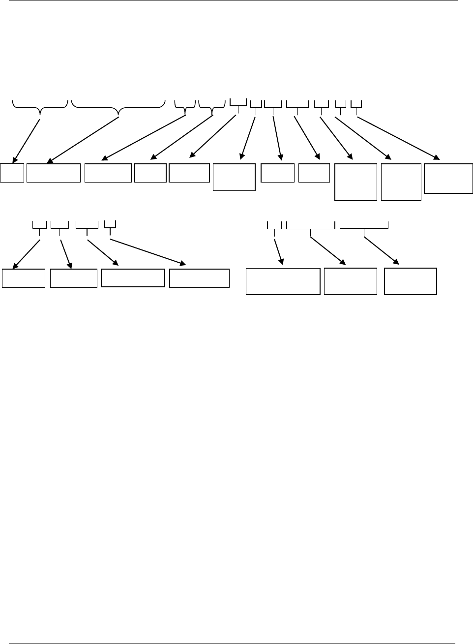
All messages
259 (285)
Calculation example: Message sends a Torque trace that has unit Nm and a Coefficient = 100
(PID=02213 has Data value=100) the Trace sample value = 5610, this means that the Torque is
5610/100 means that torque is 56,1[Nm] or by PID = 02214 =5610 * 0,001.
Message example:
Sign | is not in message. Used only for increasing the readability.
|0012345678|2013-11-10:17:32:16|001|01301|003|01|000|0000|023|02|01|………
……001|001|02213|01……… …NUL|0x01|0x02|0x02|0x04…
ID
Time Stamp
N. param
PID
Length
D. type
UI
Unit
Step
Bolt
number
Trace
type
Torque
Trans ducer
type
Unit Nm
N. param
PID Coefficient
D. type UI
NUL char before all
binary data
First
Trace sample
Next
Trace sample

All messages
260 (285)
5.27.1.1 Subscribe, MID 0900 Trace data message
Used by the integrator to subscribe on trace data. MID is used together with MID 0008, see Table 21
MID 0008, revision 1, this begins at byte 30 after the message header.
Message sent by: Integrator
Answer: MID 0005 Command accepted with MID 900 in the data field or
MID 0004 Command error with MID 900 in the data field and error code,
Subscription MID Revision unsupported or Subscription already exist or
Subscription on specific data not supported or Invalid data
Table 158 Extra data field for subscription MID 900, revision 1
Parameter
Size [byte]
Data type
Description
Send
alternatives
1
UI
Following alternatives are available.
One ASCII digit 0=Only new data, 1= Stored data from given index, 2
Stored data from given time stamp, 3 Stored data between two indexes, 4
Stored data between two given time stamps in Unix time ( Seconds since
1970-01-01)..
If = 0 then only the last data stored and data stored after that the
subscription is done is sent to the subscriber. Old unsent data will not be
sent to the subscriber.
If = 1 the data from given INDEX is sent inclusive the latest stored.
If = 2 the data from given time stamp in Unix format is sent inclusive the
latest stored.
If = 3 the data between two given indexes is sent
If = 4 the data between two given time stamps in Unix time is sent
STRUCTURE FOR ALTERNATIVE 0-2
Data Identifier
Time Stamp
type
19
T
The identifier is a Time stamp of the requested data.
The first data sent will be the first data and inclusive this time stamp and
forward up to and inclusive the last one.
If the data is not found, rewind will be to oldest possible data.
All data from this point up to the newest available will be sent directly on
subscribe.
If not used filled in with zeroes e.g at alternative 1.
At alternative 2 it contains the Time Stamp ex. 2015.10.01:19:01:30.
Data Identifier
Index type or
unix time type
10
UI
The Identifier INDEX or the UNIX time (at Alternative 2) of the data to
rewind to. 10 bytes. Only used for old stored process data.
The first data sent will be the data from and inclusive this point and
forward up to and inclusive the last one.
If the data is not found, or if the value is 0, rewind will be to oldest
possible data.
All data from this point up to the newest available will be sent directly on subscribe.
Send object data
1
B
Start subscription of MID 1202. It is not possible to only start subscription
of MID 1202 without a subscription of MID 1201.
STRUCTURE FOR ALTERNATIVE 3
Data Identifier
First index
10
UI
The first identifier is an index result id.
The first data sent will be the first data, this index included.
If the data is not found, there will be reported error.
All data from this point up to the last given index will be sent directly on
subscribe if found, else error.

All messages
261 (285)
Data Identifier
Last Index
10
UI
The second Identifier is an index result id.
Send object data
1
B
Start subscription of MID 1202. It is not possible to only start subscription
of MID 1202 without a subscription of MID 1201.
STRUCTURE FOR ALTERNATIVE 4
Data Identifier
First Unix time
10
UI
The first identifier is an Unix time = Seconds since 1970-01-01.
The first data sent will be the first data after this time.
If the data is not found, there will be reported error.
All data from this point up to the second given time will be sent directly on
subscribe if found, else error.
Data Identifier
Last Unix time
10
UI
The second Identifier is a Unix time.
Number of
trace types
2
UI
The number of trace types subscribed for
Trace type
3
UI
Type of the trace curve subscribed for. This field is repeated the Number
of trace types.
1 = Angle trace
2 = Torque trace
3 = Current trace
4 = Gradient trace
5 = Stroke trace
6 = Force trace
If the integrator tries to subscribe on a specific data that the controller doesn’t support, the controller
will replay with an error code MID 0004 Error 78 Subscription data not supported.
Error example: Parameter “Send only new data” is set to 2 and the controller doesn’t support that, the
controller will replay “MID 0004 Error 78 Subscription data not supported”
or
Parameter “Trace type” is set to 5 and the controller doesn’t support that, the controller will replay
“MID 0004 Error 78 Subscription data not supported”
Example: Subscribe on Angle Trace data, stored after that the subscription is done, using MID 0008
combined with MID 0900.
Send only new data=0,
Data Identifier Time Stamp type = N/A
Data Identifier Index type = N/A
Number of trace types = 01
Trace type = 001
<Data Field design>: MID[4];MIDRev[3];Length[2];ExtraData[2+n*3];NUL
The bold data is the data in the ‘Extra Data Field’ that begins at byte 30, and here it starts with a zero.
This means that the subscription is set to send only new data.
Then 29 spaces are sent since those fields are not needed and finally we have one trace of type Angle.
<Header ><DataField ><NUL>
006400080010 0900001350 01001NUL

All messages
262 (285)
5.27.1.2 Unsubscribe, MID 0900 Trace curve data message
MID 0900 is used together with MID 0009 it will unsubscribe on trace data.
Message sent by: Integrator
Answer: MID 0005 Command accepted with MID 900 in the data field or
MID 0004 Command error with MID 900 in the data field with error code,
Subscription not exist or Subscription on specific data not supported or Invalid
data
Table below describe the parameter “Extra data” byte nr 30 in MID 0009 and is a part of the Data
field. For a more detailed description see Table 22 MID 0009, revision 1
Example: Trace data message unsubscription on Angle using MID 0009
<Data Field design>: MID[4]; MIDRev[3]; Length[2]; ExtraData[2+n*3]; NUL
Table 159 Extra data field for unsubscription MID 900, revision 1
Parameter
Size
[byte]
Data
type
Description
Number of trace
types
2
UI
The number of trace types to unsubscribe
Trace type
3
UI
Type of the trace curve to unsubscribe. This field is repeated the Number of trace
types.
1 = Angle trace
2 = Torque trace
3 = Current trace
4 = Gradient trace
5 = Stroke trace
6 = Force trace
999 = Unsubscribe on all
If unsubscribe is done on a specific trace type it automatically unsubscribes on the plotting data for
that trace type as well.
<Header ><Data Field ><NUL>
003400090010 09000010601001NUL

All messages
263 (285)
5.27.2 MID 0901 Traces Plot Parameters Message
This MID contains all trace plotting parameters necessary for drawing of the limit figures in relation to
the trace curve. The plotting parameters sent are dependent on the Trace types subscribed for. If both
Torque and Angle trace are subscribed for also the Plot parameters for all possible limit figures will be
sent
Message sent by: Controller
Answer: MID 0005 Command accepted
Table below descriptions the “Data field” that begins at byte 21 after the message header.
All PID’s is to be described in Chapter “6.4 Parameter ID numbers”
Table 160 MID 901 data field, revision 1
Parameter
Size
[byte]
Data
type
Description
Result Data Identifier
10
UI
The Result Data Identifier is a unique ID for each operation result
within the system.
Time stamp
19
T
Time stamp for each operation sent to the control station. The time is
19 byte long and is specified by 19 ASCII characters (YYYY-MM-
DD:HH:MM:SS)
Number of PID’s
(parameter data fields,
specific)
3
UI
The number of variable data fields in the telegram. If no data fields
exist “000” will be sent.
Data fields
Vary
This section is repeated “Number of data fields” times. If Number of
data fields = 000, this section is not sent. . Each Data field strructure is
of variable parameter type see Variable Data Field Use
Example: Subscription is made on plotting parameters. The controller will send plotting limits for
Torque over time plane
LL |MID |Rev|N|........|ResDataId |TIMESTamp |NPI| PID |ll |DT|U |S.No|data value |
00xx|0009|001|0| |0000000001|YYYY-MM-DD:HH:MM:SS|00x|00000|000|00|000|0000|... |NUL

All messages
264 (285)
5.27.2.1 Subscribe, MID 0901 Trace plotting parameter
Used by the integrator to subscribe on trace data. MID 0901 is used together with MID 0008
Application data message subscription. No extra data is needed after the message header.
Message sent by: Integrator
Answer: MID 0005 Command accepted with MID 901 in the data field or
MID 0004 Command error with MID 901 in the data field and with error code,
Subscription already exist or Subscription does not exists or Invalid data
The number of plotting parameters that is sent is according to respective Controller and according to
what trace type that is subscribed for.
Example: If there Controller support Angle Trace and that trace type is subscribed for plus the plotting
parameter, the Plotting limits for Angle vs. Time will be sent.
If there was no subscription on any trace type the controller will answer with MID 0004 Command error
Subscription does not exists.
5.27.2.2 Unsubscribe, MID 0901 Trace plotting parameter
Used by the integrator to subscribe on trace data. MID 0901 is used together with MID 0009
Application Data Message unsubscribe. No extra data is needed after the message header.
Message sent by: Integrator
Answer: MID 0005 Command accepted or
MID 0004 Command error, Subscription not exist or Invalid data

All messages
265 (285)
5.28 Application Keep alive message
5.28.1 MID 9999 Keep alive message
The integrator sends a keep alive to the controller. The controller should only mirror and return the
received keep alive to the integrator.
The controller has a communication timeout equal to 15s. This means that if no message has been
exchanged between the integrator and the controller for the last 15s, then the controller considers the
connection lost and closes it.
In order to keep the communication alive the integrator must send a keep alive to the controller with a
time interval lower than 15s.
Note: An inactivity timeout is suggested to integrator i.e. if no message has been exchanged (sent or
received) during the last 10s, send a keep alive.
Message sent by: Integrator
Answer: The same message mirrored by the controller.
For header description see section 2.2.2!

Unit /Parameter ID/Data Type definitions
266 (285)
6 Unit /Parameter ID/Data Type definitions
In this chapter are valid unit types, parameter ID numbers and Data Types defined for the variable data
field pattern structure.
These lists will be typically updated over time, when new unit’s types and parameter IDs are wanted to
be added.
6.1 Data Type definitions
Below is shown the Data Type definitions which has the Format: Max 2 ASCII characters
Format: 2 ASCII characters
Table 161 Data type definitions
Value
sent in
telegram
Type
Length
Description
01
UI
Variable
The value is an unsigned integer. The number of digits are defined with the
Length parameter
02
I
Variable
The value is a signed integer. The number of digits are defined with the Length
parameter
03
F
Variable
The value is sent as a float value with the layout “12.12”, “10025.1234” or “-
57.5” etc.
It is up to the sender of the telegram to decide the number of decimals to
send.
The number of characters sent varies depending on the size and resolution of
the sent number.
04
S
Variable
The value is a string. Sent as ASCII characters, the length of the data fits the
actual length of the string. Note that the string may contain spaces (ASCII
character 0x20)
05
T
19
A time specified by 19 ASCII characters (YYYY-MM-DD:HH:MM:SS)
06
B
1
A boolean value, one ASCII digit, 0 = FALSE and 1 = TRUE
07
H
Variable
Hexadecimal value. Sent as ASCII characters, example “A24CD3”.
08
PL1
Variable
Plotting point consisting of a FA of one pair of float values where the first value
is the Y and the second is the X within the pair.
09
PL2
Variable
Plotting point consisting of a FA of two pairs of float values where the first
value is the Y and the second is the X within a pair.
10
PL4
Variable
Plotting point consisting of a FA of 4 pairs of float values where the first value
is the Y and the second is the X within a pair.
50
FA
Variable
Array of Float. Each float value is sent as 8 ASCII characters. Negative values
start with a ‘-‘ sign. The precision of the values vary, for large values decimal
point is omitted. Valid values are for example “-1234567”, “001.1205”, “-
123.789”
51
UA
Variable
Array of Unsigned integers. Each integer value is sent as 8 ASCII characters
Valid values are for example “12345678”, “00001234”, “00200000”

Unit /Parameter ID/Data Type definitions
267 (285)
52
IA
Variable
Array of Signed integers. Each integer value is sent as 8 ASCII characters.
Negative values start with a ‘-‘ sign. Valid values are for example “12345678”,
“-1234567”, “00200000”, “10200000”
6.2 Trace Plotting type figures definitions
The following plotting figure types are defined.
LINE, high or low. When using data type of ether FA
POINT, single point. When using data type PL1
WINDOW, 4 plot points with lines drawn between and filled. When using data type PL4
DOUBLE ARROW LINE, 2 plot points with double arrow line between. When using data
type PL2
6.3 Unit types definitions
Below is shown the Data Type definitions which has the Format: 3 ASCII characters
Table 162 Unit type definitions
Value sent in telegram
Unit
000
No unit
Torque units
001
N·m (Newton meter)
002
ft lbf (foot-pound force)
003
cN·m (centi Newton meter)
004
kN·m (kilo Newton meter)
005
MN·m (Mega Newton meter)
006
in lbf (inch-pound force)
007
Kpm (kilo pound meter)
008
Kfcnm (Kilo centi force)
009
%
010
Ozf-in
011
dNm
Angle units
050
° (Degree)
051
rad (radian)

Unit /Parameter ID/Data Type definitions
268 (285)
Frequency units
100
Hz (hertz)
101
rpm (revolutions per minute)
Torque rate units
150
N·m / ° (Newton meter / degree)
151
ft lbf / ° (foot-pound force / degree)
152
cN·m / ° (centi Newton meter / degree)
153
kN·m / ° (kilo Newton meter / degree)
154
MN·m / ° (mega Newton meter / degree)
155
in lbf / ° (inch-pound force / degree)
160
N·m / rad (Newton meter / rad)
161
ft lbf / rad (foot-pound force / degree)
162
cN·m / rad (centi Newton meter / degree)
Time units
200
s (second)
201
min (minute)
202
ms (milliseconds)
203
h (hour)
Temperature units
250
K (kelvin)
251
°C (degree Celsius)
252
°F (degree Fahrenheit)
Force units
300
N (newton)
301
kN (kilo newton)
302
lbf (pound-force)
303
kgf (kilogram-force)
304
ozf (ounce-force)
305
MN (mega newton)
Length units
350
m (meter)
351
mm (millimeter)
352
in (inch)
Speed units
400
m/s (meter per second)
401
mm/s (millimeter per second)

Unit /Parameter ID/Data Type definitions
269 (285)
Force rate units
450
N / mm (newton / millimeter)
451
kN / mm (kilo newton / millimeter)
452
lbf / in (pound-force / inch)
453
Kgf / mm (kilogram-force / millimeter)
454
Ozf / in (ounce-force / inch)
455
MN / mm (mega newton / millimeter)
Acceleration units
500
m/s
2
(meter per second squared)
501
mm/s
2
(millimeter per second squared)
Mass units
550
kg (kilogram)
551
lb (pound)
Volume units
600
L (liter)
601
m
3
(cubic meter)
Area units
650
m
2
(square meter)
Power units
700
W (Watt)
Electric units
750
A (Ampere)
751
V (Volt)
752
Ω (ohm)
753
F (farad)
754
H (henry)
Other units
800
% (percentage)
Plotting units
900
N·m / ms (Y = Newton meter, X = milliseconds)
901
ft lbf / ms (Y = foot-pound force, X = milliseconds)
902
cN·m / ms (Y = centi Newton meter, X = milliseconds)
903
kN·m / ms (Y = kilo Newton meter, X = milliseconds)
904
MN·m / ms (Y = mega Newton meter, X = milliseconds)

Unit /Parameter ID/Data Type definitions
270 (285)
905
in lbf / ms (Y = inch-pound force, X = milliseconds)
910
° / ms (Y = Degree, X = milliseconds)
911
rad / ms (Y = Radian, X = milliseconds)
920
N / ms (Y = newton, X = milliseconds)
921
kN / ms (Y = kilo newton, X = milliseconds)
922
Lbf / ms (Y = pound-force, X = milliseconds)
923
kgf / ms (Y = kilogram-force, X = milliseconds)
924
ozf / ms (Y = ounce-force, X = milliseconds)
925
MN / ms (Y = mega newton, X = milliseconds)
6.4 Parameter ID numbers
Below is shown parameter IDs that are common for all systems using open protocol.
Format: 5 ASCII digits
Table 163 Parameter IDs definitions common
Parameter id
(PID)
Name
Description
Statuses
00001
Tightening Status
The overall status of all the tools in the tightening.
0=NOK
1=OK
00002
Station ID
The station id is a unique id for each station. In ASCCI
figures 0-9
00003
Station Name
The station name. In ASCII characters.
Identifiers
00010
VIN Number
The VIN number for the tightening
00011
Identifier 1
Identifier 1 used for the tightening. Could for example
be a pallet number, identity of the operator,
identification for the part, etc…
00012
Identifier 2
…
00013
Identifier 3
…
00014
Identifier 4
…
00015
Identifier 5
…
00016
Identifier 6
…

Unit /Parameter ID/Data Type definitions
271 (285)
Parameter id
(PID)
Name
Description
00017
Identifier 7
…
00018
Identifier 8
…
00019
Identifier 9
…
00020
Identifier 10
Identifier 10 used for the tightening. Could for example
be a pallet number, identity of the operator,
identification for the part, etc…
00030
Tightening Identifier
Identifier for tightening 10 figures long.
00031
Identifier handling
Types of handling can be:
1 = Reset the latest identifier
2 = Reset all identifiers
3 = Bypass to next identifier in a list of identifiers to be
used for next tightening
00050
Oldest result Id
Oldest result Id in a controller result database. 32 bit
00051
Latest result Id
Latest result Id in a controller result database. 32 bit
00052
Oldest result Time
Oldest result Time in a controller result database. Unix
time
00053
Latest result Time
Latest result Time in a controller result database. Unix
time
Event parameter
00040
Events
System common. But content unique for each system.
Batch parameters
00100
Batch size
This parameter gives the total number of tightenings in
the batch. Only used if this tightening was a part of a
batch.
00101
Batch counter
The number for this tightening in the batch. Only used if
this tightening was a part of a batch.
00102
Batch status
The current status of the batch. Only used if this
tightening was a part of a batch.
0=Batch not completed
1=Batch completed
2=No bath
00103
Batch count
0 = Off, 1 = Pset, 2 = Fieldbus, 3 = Ethernet/Serial
Tightening program information
01000
Tightening program Number
The number or index of the tightening program or Pset
that made the tightening
01001
Tightening program Name
The name of the tightening program or Pset that made
the tightening

Unit /Parameter ID/Data Type definitions
272 (285)
Parameter id
(PID)
Name
Description
01002
Control Tightening program
Strategy
The overall strategy used in the tightening program.
Possible strategies are:
01=Torque control
02=Torque control / angle monitoring
03=Torque control / angle control AND
04=Angle control / torque monitoring
05=DS control
06=DS control torque monitoring
07=Reverse angle
08=Reverse torque
09=Click wrench
10=Rotate spindle forward
11=Torque control angle control OR
12=Rotate spindle reverse
13=Home position forward
14=EP Monitoring
15=Yield
16=EP Fixed
17=EP Control
18=EP Angle shutoff
19=Yield / torque control OR
20=Snug gradient
21=Residual torque / Time
22=Residual torque / Angle
23=Breakaway peak
24=Loose and tightening
25=Home position reverse
26=PVT comp with Snug
27 =Batch
28 = PVT Monitoring
29 = PVT Compensate
30 = Self-tap
31 = Rundown
32 = CM
33 = Four Stage tightening torque
34 = Four Stage tightening angle
35 = STW Loosening
01003
Time of last change in tightening
program settings
Date and time of last change in tightening program
settings
01004
Number of steps
The number of steps in the tightening program
01005
Tightening Strategy
One stage = 0, Two stage = 1, Quick step = 2, Ergo
ramp = 3
01006
Trace Tool Start
Start trace from Start = 0 or Cycle Start = 1
01007
Cycle Tool Start
Torque value from where the tightening cycle is
considered as started.
01008
Remove fastener limit
Torque value for the limit at which the fastener shall be
removed.
01009
Measure Torque at
Torque result measured at Torque peak = 0, Angle
peak = 1 or Shut off angle = 2
01010
Monitor Angle High limit
High limit for monitor Angle High Limit
01011
Measure Angle to
Torque peak = 0, Angle peak = 1, Cycle complete = 2,
Shut off = 3 or Not used = 4

Unit /Parameter ID/Data Type definitions
273 (285)
Parameter id
(PID)
Name
Description
01012
Re-hit Angle
Degree value for re-hit detection
01013
Zoom Step Speed
Can be in percent or RPM of tool maximal speed
01014
Ergo Ramp
Can be in percent or RPM of tool maximal speed
01015
Reserved
Reserved
01016
Tool Idle time
Time after rundown done until result is sent, especially
used when Multistage tightening is used
01017
End Time
Time for slip off detection
01018
Monitor End Time from
When starting detection of End time. Cycle Start = 0 or
Rundown Complete = 1
01019
Tight time out sec
Time out value in second before not finished Job is
aborted.
01020
Max Coherent NOK
Max number of coherent NOK results allowed
01021
High Speed Rundown Used
Not used = 0, Used = 1
01022
High Speed Rundown Speed
Speed in percent of tool max
01023
High Speed Rundown Interval
Value in degrees for the interval of the first part of the
rundown before snag
01024
High Speed Rundown Ramp at
High Speed
Acceleration factor in percent
01025
High Speed Rundown Disable High
Speed at NOK
No = 0, Yes = 1
01026
Options Used
No = 0, Yes = 1
01027
Options Soft Stop
Yes = 0, No = 1
01028
Options Re-hit Detect
No = 0, Yes = 1
01029
Options Torque < Target Detect
No = 0, Yes = 1
01030
Options Lost trigger detect
No = 0, Yes = 1
01031
Options Socket Release Detect
No = 0, Yes = 1
01032
Self-Tap Monitoring Speed Rpm
01033
Measured Delay Time
01034
Ds Tuning value
01035
Options Timeout detect
01036
Used strategies
Used strategies as a bit field. Measured value
01037
Tightening error bits 1
01038
Tightening error bits 2

Unit /Parameter ID/Data Type definitions
274 (285)
Parameter id
(PID)
Name
Description
01039
Result type
TIGHTENING_RES = 1
LOOSENING_RES = 2
SYNC_TIGHTENING_RES = 3
SYNC_LOOSENING_RES = 4
CLICK_WRENCH_RES = 5
INCREMENT_RES = 6
DECREMENT_RES = 7
RESET_BATCH_R9S = 8
BYPASS_RES = 9
ABORT_JOB_RES = 10
EP_AUTOPROG_RES = 11
SYNC_NO_TIGHTENING_RES = 12
POSITIONING_RES = 13
EP_UNTUNED_RES = 14
LATE_RES = 15
TQ_WITH_NO_PSET_RES 16
RADIO_WORK_ORDER_ABORT 17
STW_LOOSENING_RES 18
01040
Dynamic Pset Id
The Id of a dynamic Pset
01041
Dynamic Pset Name
The name of a dynamic Pset
Torque controller information
01100
Torque controller Name
The name of the torque controller that made the
tightening
01101
Torque controller Number
The number of the torque controller that made the
tightening.
01102
Torque controller type name
The type name of the controller that made the
tightening.
01103
Torque controller article number
The article number of the torque controller that made
the tightening. Will be sent as a string
01104
Torque controller serial number
The serial number of the torque controller that made the
tightening. Will be sent as a string
Tool information
01200
Tool type name
The type name of the tool that made the tightening.
Could for example be “QST50-150CTT”
01201
Tool article number
The article number of the tool that made the tightening.
Will be sent as a string
01202
Tool serial number
The serial number of the tool that made the tightening.
Will be sent as a string
01203
Tool type
00=No Tool, 01=S-tool, 02=DS-tool, 03=Ref.
transducer, 04=ST-tool, 05=EP-tool, 06=ETX-tool,
07=SL-tool, 08=DL-tool, 09=IRC Offline, 10=STB-tool,
11=QST-tool, 12=STT-tool, 13=ST wrench, 14 = ES-
tool, 15 = ESB, 16 = SB, 17 = SB+
01204
Speed Factor

Unit /Parameter ID/Data Type definitions
275 (285)
Parameter id
(PID)
Name
Description
01210
Tool total number of tightenings
The total number of tightenings made with the tool
01211
Tool total number of tightenings
since service
The total number of tightenings made with the tool
since last service
01212
Tool total number of tightenings to
service
The total number of tightenings before the tool need to
be serviced
Bolt information
01300
Bolt Name
The name of the bolt that was tightened
01301
Bolt Number
The number of the bolt that was tightened
01302
Bolt Status
The status of the bolt that was tightened
Error and status codes
01400
Tightening Status
The total status of the tightening
0 = Tightening NOK
1 = Tightening OK
01401
Tightening error codes
Error codes from the tightening. Is defined by a bit field
and sent as a hexadecimal value, i.e. Data Type will be
set to H in the telegram.
The number of bits and their definition vary between the
different systems.
01402
Torque status
The status of the Torque in the tightening
Based on the parameter 02001
0=Low, 1=OK, 2=High
01403
Angle status
The status of the Angle in the tightening
Based on the parameter 02011
0=Low, 1=OK, 2=High
01404
Rundown Monitor status
The status of the Rundown monitoring in the tightening
Based on the parameters 02016-2018
0=Low, 1=OK, 2=High
01405
Current Monitor status
The status of the Current monitoring in the tightening
Based on the parameters 02020-02023
0=Low, 1=OK, 2=High
01406
Self Tap Status
The status of the Self tap monitoring in the tightening
Based on the parameters 02070-02071
0=Low, 1=OK, 2=High
01407
PVT Monitor status
The status of the PVT monitoring in the tightening
Based on the parameter 02078
0=Low, 1=OK, 2=High
01408
PVT Comp status
The status of the PVT Comp monitoring in the
tightening.
Based on the parameters 02072-02073
0=Low, 1=OK, 2=High
Job/Sync parameters
01500
Job ID
ID of a Job
01501
Job sequence number
Job result sequence

Unit /Parameter ID/Data Type definitions
276 (285)
Parameter id
(PID)
Name
Description
01502
Job stage number
Stage within an Job
01503
Job time stamp
The last time the Job configuration was changed
01504
Sync Group ID
Id of a sync group or station.
01505
Sync Group Name
Name of a sync group or station.
01506
Sync Group Status
Status of a sync group or station
01507
Sync Tightening Id
The Id of a result from an sync tightening
01508
Job Start Time
The time stamp of Job started
01509
Job Reference Mac address
The Reference Mac address for Job result when cell is
used
01510
Job result Id
Identifier number of Job
01511
Auto Pset change
A Boolean. 1 =Auto change 0= BY hand
01512
Pset/Mset type
01513
Pset/Mset channel Id
Channel Id of Pset/Mset when cell is used
01514
Stop time
Time when the Job was ended or stopped
01515
First NOK Event
First NOK stage in Job
01516
Job done status
0 = Job off, 1 = Running, 2 = OK, 3 = NOK, 4 =
ABORTED
Tightening values
02000
Torque, final target
The target torque for the whole tightening program
02001
Torque, measured value
The measured torque for the whole tightening.
02002
Torque, final upper limit
The upper limit for the measured torque of the whole
program.
02003
Torque, final lower limit
The lower limit for the measured torque of the whole
program.
02004
Torque, first target
The first target in a two step
02005
Torque, cycle start
Torque value where the tightening measurement starts
after tightening start
02006
Torque, cycle complete
Torque value where the tightening measurement starts
before complete
02010
Angle, target
The target angle for the whole tightening program
02011
Angle, measured value
The measured angle for the whole tightening.
02012
Angle, upper limit
The upper limit for the measured angle, for the whole
tightening
02013
Angle, lower limit
The lower limit for the measured angle, for the whole
tightening
02014
Angle target threshold torque cycle
start
The torque value at which the angle measurement start
at the cycle start
02015
Angle target threshold torque cycle
end
The torque value at which the angle measurement start
at the cycle end
02016
Angle Max Rundown
The max allowed angle value target measured
according to parameter 2043

Unit /Parameter ID/Data Type definitions
277 (285)
Parameter id
(PID)
Name
Description
02017
Angle Min Rundown
The min angle allowed value target measured
according to parameter 2043
02018
Angle max to monitor
The max value of the angle to measure
02019
Torque, Rundown complete torque
02020
Current, target
The target current for the whole tightening program
02021
Current, measured value
The measured current for the whole tightening.
02022
Current, upper limit
The upper limit for the measured current
02023
Current, lower limit
The lower limit for the measured current
02030
Torque 2nd, measured value
The measured torque for the whole tightening.
Measured with a secondary torque transducer.
02031
Torque 2nd, upper limit
The upper limit for the measured torque 2nd.
02032
Torque 2nd, lower limit
The lower limit for the measured torque 2nd.
02040
Angle 2nd, measured value
The measured angle for the whole tightening.
Measured with a secondary angle transducer.
02041
Angle 2nd, upper limit
The upper limit for the measured angle 2
nd
02042
Angle 2nd, lower limit
The lower limit for the measured angle 2nd
02043
Rundown Angle
The rundown angle selection is = 0 (No), 1 (From start)
and 2 (From cycle start)
02044
Rundown Angle measured value
02050
Speed, target
The target speed for the whole tightening program
02051
Speed, measured
The measured speed for the whole tightening program
02052
Step Speed
The target speed for the each step
02053
Reserved
Reserved
02054
Soft start time
The time duration for the soft start in a tightening
02055
Soft start speed
The tightening speed during the soft start time duration
either in ratio or percent of the tool max speed.
02056
Step Ramp
The tightening speed increase per time unit during the
step.
02057
Reserved
Reserved
02058
Lock at batch done
0 = No, 1 = Yes
02059
Necking shut off
Antinecking detection for angle control strategies.
0 = No, 1= Yes
02060
Rotate Direction
CW = 1, CCW = 2
02061
Self-tap
Self-tap on or off 0 = off, 1= on
02062
Number of self-tap windows
At least 1
02064
Necking drop torque from peak
02070
Self-tap Max Torque
The max tightening torque value for the self-tap
measurement validation.

Unit /Parameter ID/Data Type definitions
278 (285)
Parameter id
(PID)
Name
Description
02071
Self-tap Min Torque
The min tightening torque value for the self-tap
measurement validation.
02072
Prevail Torque Max
The max tightening torque value for the prevail
measurement validation.
02073
Prevail Torque Min
The min tightening torque value for the prevail
measurement validation.
02074
Yield Max
02075
Yield Min
02076
Prevail
Prevail on or off 0 = off, 1= on
02077
Prevail Comp
Prevail Comp on or off 0 = off, 1= on
02078
Prevail comp point angle
Angle value
02079
Number of prevail windows
At least 1 is required
02080
Post View Torque Min Limit
Torque float value for the low limit in Torque trace
02081
Post View Torque Max Limit
Torque float value for the high limit inn Torque trace
02082
Prevail Comp Measured Torque
02084
Self-tap monitor interval
The interval duration in degrees for self-tap
measurements according to parameters 02070 and
02071
02085
Prevail Torque Delay Interval
Delay from cycle start to the start of Prevail Torque
Monitor Interval
02086
Prevail Torque Monitor Interval
The interval duration in degrees for prevail
measurements according to parameters 02072 and
02073
02087
Post View Torque Monitor Min Start
Post View Torque in Angle trace
02088
Post View Torque Monitor Min
Interval
Post View Torque in Angle trace
02089
Post View Torque Monitor Max Start
Post View Torque in Angle trace
02090
Post View Torque Monitor Max
Interval
Post View Torque in Angle trace
02091
Post View Torque
Post View Torque monitoring on or off 0 = off, 1= on
02092
Self-tap Torque measured value
02093
Prevail Torque measured value
02094
Attachment Gear ratio
02095
Attachment tuning. Efficiency tuning
02100
Loosening limit torque
Torque threshold for loosening detection
02101
Loosening speed
Speed according to parameter 02103
02102
Loosening ramp
Ramp according to parameter 02103
02103
Speed unit
Unit for speed in percent = 0 or rpm = 1
02110
Force, final target
The target force for the whole program
02111
Force, measured value
The measured force for the whole press.

Unit /Parameter ID/Data Type definitions
279 (285)
Parameter id
(PID)
Name
Description
02112
Force, final upper limit
The upper limit for the measured force, for the whole
program
02113
Force, final lower limit
The lower limit for the measured force. for the whole
program
02120
Stroke, target
The target stroke for the whole program
02121
Stroke, measured value
The measured stroke for the whole program.
02122
Stroke, upper limit
The upper limit for the measured stroke, for the whole
program
02123
Stroke, lower limit
The lower limit for the measured stroke, for the whole
program
02124
Free Event Text
User defined event text
02130
Four stage soft start angle
Starting value in degrees for an four stage tightening
02131
Four stage soft start angle torque
max
Max value for soft start torque in Nm during soft start
02132
Four stage first target angle min
Min value in degrees for first target in an four stage
tightening
02133
Four stage first target angle max
Max value in degrees for first target in an four stage
tightening
02134
Four stage torque, measured value
The measured torque for one stage of a four stage
tightening
02135
Four stage angle, measured value
The measured angle for one stage of a four stage
tightening
02136
Four stage status angle, measured
value
The status for one stage angle of a four stage
tightening. Value = 0 = NOK. Value = 1 = OK.
02129
Four stage status torque measured
value
The status for one stage torque of a four stage
tightening. Value = 0 = NOK. Value = 1 = OK.
02137
Gradient monitoring
Gradient monitoring on or off 0 = off, 1= on
02138
Gradient torque min
Torque Value in Nm
02139
Gradient torque max
Torque Value in Nm
02140
Gradient Joint hardness
Angle value in degrees
02141
Gradient Start torque
Torque value in Nm
02142
Gradient Angle offset
Angle value in degrees
02143
Yield control Start torque
Torque value in Nm
02144
Yield control Step angle
Angle value in degrees for one step
02145
Yield control window angle
Angle value in degrees
02146
Yield slope ratio
In percent
02147
Yield control Extra Angle step
Angle extra value for one step
02150
Positioning Adjustable limit
Adjustable limit on or off. 0 = off, 1= on
02151
Positioning limit
Value in Nm
02152
Snug gradient delta angle
Value in degrees
02153
Snug gradient delta torque
Value in torque Nm
02154
Snug gradient Torque limit
Value in torque Nm

Unit /Parameter ID/Data Type definitions
280 (285)
Parameter id
(PID)
Name
Description
02155
Snug gradient PVT distance
Value in degrees
02156
Snug gradient PVT interval
Value in degrees
02157
Snug gradient Compensate
Value in degrees
02158
Snug PVT Monitoring min
Value in torque Nm
02159
Snug PVT Monitoring max
Value in torque Nm
02160
Delay monitoring after cycle start
Value in degrees
Tightening values for trace
02201
Trace type
Type of the trace curve
1 = Angle trace
2 = Torque trace
3 = Current trace
4 = Gradient trace
5 = Stroke trace
6 = Force
02213
Coefficient
Coefficient to convert 2 byte binary data to real physical
values.
Physical value = Binary value / Coefficient
02214
Coefficient
Coefficient to convert 2 byte binary data to real physical
values.
Physical value = Binary value * Coefficient
02215
Stage one number of samples
Number of samples for stage one at four stage
tightening
02216
Stage two number of samples
Number of samples for stage two at four stage
tightening
02217
Stage three number of samples
Number of samples for stage three at four stage
tightening
02218
Stage four number of samples
Number of samples for stage four at four stage
tightening
General download data status for Radio Connected Tools
04000
Tool latest Pset status
A Boolean = 0 Latest Pset failed to tool. 1 = Latest Pset
success to tool
04001
Tool latest Identifier status
A Boolean 0 = Latest Identifiers failed to tool, 1=
Success to tool
04002
Tool lock/unlock status
A Boolean = 0 = Tool unsuccessfully locked/unlocked
1 = Tool successfully locked/unlocked
Step information

Unit /Parameter ID/Data Type definitions
281 (285)
Parameter id
(PID)
Name
Description
05000
Tightening step strategy
The overall strategy used in the tightening program step
Possible strategies are:
01=Torque control
02=Angle control
03=Backlash correction
04=Diagnostic
05=DynaTork
06=Engage
07=JOG
08=Run to position
09=Run until snug
10=Socket release
11=Time control
12=Wait
13=Yield point
05001
Step error codes
Error codes from the tightening program step. Is
defined by a bit field and sent as a hexadecimal value,
i.e. Data Type will be set to H in the telegram.
The number of bits and their definition vary between the
different systems.
05002
Step name
Name of the tightening program step
Step Tightening values
05100
Step Torque, target
The target torque for the tightening program step
05101
Step Torque, measured value
The measured torque for the tightening program step
05102
Step Torque, upper limit
The upper limit for the measured step torque.
05103
Step Torque, lower limit
The lower limit for the measured step torque.
05110
Step Angle, target
The target angle for the tightening program step
05111
Step Angle target threshold torque
The torque value there the angle measurement start
05112
Step Angle, measured value
The measured angle for tightening program step
05113
Step Angle, upper limit
The upper limit for the measured step angle
05114
Step Angle, lower limit
The lower limit for the measured step angle
05120
Step Current, target
The target current for the tightening program step
05121
Step Current, measured value
The measured current for tightening program step
05122
Step Current, upper limit
The upper limit for the measured step current
05123
Step Current, lower limit
The lower limit for the measured step current
05130
Step Force, target
The target force for the tightening program step
05131
Step Force, measured value
The measured force for the tightening program step
05132
Step Force, upper limit
The upper limit for the measured step force.
05133
Step Force, lower limit
The lower limit for the measured step force.
05140
Step Stroke, target
The target stroke for the tightening program step
05141
Step Stroke target threshold force
The force value there the stroke measurement start

Unit /Parameter ID/Data Type definitions
282 (285)
Parameter id
(PID)
Name
Description
05142
Step Stroke, measured value
The measured stroke for tightening program step
05143
Step Stroke, upper limit
The upper limit for the measured step stroke
05144
Step Stroke, lower limit
The lower limit for the measured step stroke
05150
Step Start
Calculated from the Time Stamp
05151
Step Stop
Calculated from the Time Stamp

Unit /Parameter ID/Data Type definitions
283 (285)
6.5 Systems Unique Parameter ID number series
Below is shown parameter IDs areas that are dedicated for systems special needs, NOT common for
all systems using open protocol. The exact use shall be described in the product/system Open Protocol
implementation description documents.
Format: 5 ASCII digits
Table 164 Parameter IDs definitions system unique
System
First PID
Last PID
PF4000
10000
14999
PM4000
15000
19999
PF6000
20000
24999
CVI
25000
29999
Micro Torque
30000
34999
