User guide
Power Focus 3000/3100/3102/4000
Control and Drive unit for TENSOR Electric Nutrunners
Atlas Copco Tools & Assembly Systems
9836 3123 01
Software Release W7.0
Edition 1
2007-04

Contents
9836 3123 01 3 (330)
Contents
1 General safety instructions................................................................................11
1.1 Work area .................................................................................................................11
1.2 Electrical safety.........................................................................................................11
1.3 Personal safety.........................................................................................................12
1.4 Service......................................................................................................................12
2 Abbreviations ......................................................................................................13
3 Introduction to Power Focus..............................................................................15
3.1 PF 4000 ....................................................................................................................15
3.1.1 Logic Configurator ...................................................................................................16
3.1.2 SynchroTork ............................................................................................................16
3.1.3 Yield control.............................................................................................................16
3.2 PF 3000/3100/3102 ..................................................................................................17
3.3 ToolsTalk PF.............................................................................................................17
3.4 ToolsNet ...................................................................................................................18
3.5 Factory Overview......................................................................................................18
3.6 Event Monitor............................................................................................................19
3.7 API............................................................................................................................19
3.8 RBU ..........................................................................................................................19
3.9 Cell............................................................................................................................20
3.10 Job............................................................................................................................20
3.11 Sync..........................................................................................................................20
3.12 Communication.........................................................................................................20
3.13 Accessories ..............................................................................................................21
3.14 Nutrunners................................................................................................................23
3.15 ACTA 3000 ...............................................................................................................23
4 Getting started with ToolsTalk PF .....................................................................25
4.1 Overview...................................................................................................................26
4.1.1 Menu list ..................................................................................................................27
4.1.2 Selection panel........................................................................................................28
4.1.3 Toolbar.....................................................................................................................29
4.1.4 PF Map ....................................................................................................................30
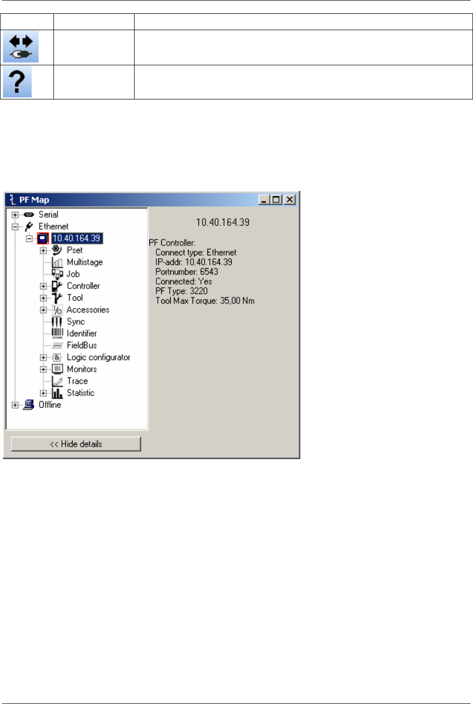
4.2 Settings.....................................................................................................................32
4.2.1 Communication........................................................................................................32
4.2.2 Application ...............................................................................................................34
4.2.3 Printout ....................................................................................................................35
4.2.4 PF List......................................................................................................................36
4.3 Connecting a PF.......................................................................................................36
4.3.1 Ethernet connection.................................................................................................36
4.3.2 Serial connection.....................................................................................................37
4.3.3 USB connection.......................................................................................................37
4.3.4 To connect...............................................................................................................37
4.3.5 To disconnect ..........................................................................................................37
4.4 Storing programming on file......................................................................................37
4.5 Offline .......................................................................................................................38

Contents
4 (330) 9836 3123 01
4.5.1 Configuring a tool offline......................................................................................... 39
5 Pset ......................................................................................................................41
5.1 Create new Pset/Open Pset.....................................................................................41
5.2 Programming............................................................................................................42
5.2.1 Control strategies.................................................................................................... 44
5.2.2 Tightening strategies .............................................................................................. 47
5.2.3 Control options........................................................................................................ 52
5.2.4 Rehit detection........................................................................................................ 52
5.2.5 Autoset.................................................................................................................... 53
5.2.6 Quick programming ................................................................................................ 54
5.2.7 Programming help .................................................................................................. 55
5.3 Programming +.........................................................................................................55
5.4 Pset setup ................................................................................................................60
5.5 Statistic programming...............................................................................................61
5.6 Running a Pset.........................................................................................................61
6 Multistage ............................................................................................................63
6.1 Create new Multistage/Open Multistage ..................................................................64
7 Job........................................................................................................................65
7.1 Create a Job group...................................................................................................67
7.2 Create new Job ........................................................................................................68
7.3 Select Job.................................................................................................................70
7.3.1 Functions in the Job monitor................................................................................... 72
7.4 Unlock the tool..........................................................................................................73
8 Controller.............................................................................................................75
8.1 Information ...............................................................................................................75
8.2 Configuration............................................................................................................76
8.3 Network ....................................................................................................................77
8.3.1 Cell and Net............................................................................................................ 79
8.4 COM ports................................................................................................................84
8.5 Display......................................................................................................................85
8.6 Memory ....................................................................................................................86
8.6.1 Store PF to file........................................................................................................ 86
8.6.2 Read PF from file.................................................................................................... 88
8.7 Accessibility..............................................................................................................89
9 Tool ......................................................................................................................91
9.1 Tool information........................................................................................................91
9.2 Tool configuration.....................................................................................................92
9.3 Tool diagnostic .........................................................................................................99
9.4 Tool maintenance...................................................................................................100
9.4.1 Motor tuning.......................................................................................................... 101
9.4.2 Disconnect tool ..................................................................................................... 102
9.4.3 Open end tuning ................................................................................................... 103
9.4.4 Tool lock functionality ........................................................................................... 104
10 Accessories.......................................................................................................109
10.1 Digital I/O................................................................................................................109
10.2 I/O bus....................................................................................................................111
10.3 Tool bus..................................................................................................................115

Contents
9836 3123 01 5 (330)
10.4 Printer .....................................................................................................................118
11 Sync ...................................................................................................................119
11.1 Hardware configuration...........................................................................................120
11.2 Sync members configuration ..................................................................................121
11.3 Sync reference configuration..................................................................................122
11.4 Running a Sync group ............................................................................................124
11.5 Troubleshooting......................................................................................................124
12 Identifier.............................................................................................................125
12.1 Single Identifier.......................................................................................................126
12.2 Multiple Identifier.....................................................................................................126
12.2.1 Work order.............................................................................................................126
12.3 Identifier types and work order ...............................................................................127
12.3.1 Result parts............................................................................................................132
12.3.2 Identifier monitor....................................................................................................134
12.3.3 Functions in identifier monitor................................................................................135
13 Field bus ............................................................................................................137
13.1 General setup .........................................................................................................137
13.2 From PF setup and to PF setup..............................................................................140
13.2.1 View Field bus information ....................................................................................141
13.2.2 Field bus modes ....................................................................................................141
13.2.3 Store to file and read from file ...............................................................................141
13.3 Field bus selector....................................................................................................142
13.4 Disable Field bus carried signals............................................................................142
13.5 Field bus configuration appendix............................................................................143
13.5.1 Bitmap select (Endian mode) ................................................................................143
13.5.2 Field bus data types ..............................................................................................143
13.5.3 Field bus selector configuration.............................................................................146
13.5.4 Items from PF........................................................................................................148
13.5.5 Items to PF ............................................................................................................159
13.5.6 ProfiBus-DP...........................................................................................................165
13.5.7 DeviceNet ..............................................................................................................168
13.6 InterBus/InterBus2MB.............................................................................................171
13.6.1 ModBusPlus...........................................................................................................173
13.6.2 EtherNet/IP ............................................................................................................176
13.6.3 ControlNet..............................................................................................................179
13.6.4 Profibus-IO.............................................................................................................180
13.6.5 FL-Net....................................................................................................................181
14 Logic Configurator............................................................................................183
14.1 Process description (an example) ..........................................................................183
14.2 Logic operators and function blocks .......................................................................184
14.2.1 Abbreviations.........................................................................................................184
14.2.2 Logic gates ............................................................................................................185
14.2.3 Function blocks......................................................................................................186
14.3 Logic Configurator setup.........................................................................................189
14.3.1 Simulation..............................................................................................................194
15 Monitors.............................................................................................................195
15.1 Result Monitor.........................................................................................................195

Contents
15.2 Job Monitor.............................................................................................................197
15.3 Operator Monitor ....................................................................................................198
15.3.1 Picture Monitor...................................................................................................... 201
15.4 Identifier Monitor.....................................................................................................202
15.5 Get all results .........................................................................................................203
16 Trace ..................................................................................................................205
17 Statistic..............................................................................................................207
17.1 Statistic in Power Focus.........................................................................................207
17.1.1 Statistical process control (SPC).......................................................................... 208
17.1.2 Statistic alarm ....................................................................................................... 208
17.1.3 Trend deviation alarm........................................................................................... 209
17.1.4 Calculation of UCL and LCL ................................................................................. 209
17.1.5 Calculation of
X
and
R
...................................................................................... 209
17.1.6 Calculation formulas ............................................................................................. 209
17.1.7 Constants for calculation of SPC variables .......................................................... 211
18 Connecting devices ..........................................................................................213
18.1 Printer.....................................................................................................................213
18.2 Serial RS232 #1 .....................................................................................................213
18.3 Serial RS232 #2 .....................................................................................................213
18.4 EtherNet/IP.............................................................................................................214
18.5 RBU........................................................................................................................214
18.5.1 Tool connector (S tools)........................................................................................ 214
18.6 Digital inputs...........................................................................................................215
18.7 Digital outputs (relays)............................................................................................215
18.8 I/O bus #1...............................................................................................................216
18.9 I/O bus #2...............................................................................................................216
18.10 Remote start connector..........................................................................................217
18.11 Main power connector............................................................................................217
19 RBU ....................................................................................................................219
19.1 RBU functionality....................................................................................................220
19.2 Connecting the RBU...............................................................................................221
19.3 Start-up instructions ...............................................................................................221
20 PF 3000 Compact user interface......................................................................223
20.1 Front panel .............................................................................................................223
20.1.1 Indicator lights....................................................................................................... 224
20.1.2 Keypad.................................................................................................................. 225
21 Tensor tools.......................................................................................................229
21.1 Tensor STB ............................................................................................................229
21.1.1 Tool functionality................................................................................................... 230
21.1.2 System setup........................................................................................................ 233
21.1.3 Crossover Ethernet cable connection................................................................... 234
21.2 Tensor ST...............................................................................................................235
21.3 Tensor SL...............................................................................................................236
21.4 Tensor S.................................................................................................................237
21.5 Tensor DS ..............................................................................................................238
21.6 Tensor ETX ............................................................................................................239
6 (330) 9836 3123 01

Contents
9836 3123 01 7 (330)
21.7 Tools with open end................................................................................................240
21.7.1 Start-up instruction ................................................................................................240
21.8 Tool accessories.....................................................................................................241
21.8.1 ST scanner ............................................................................................................241
21.8.2 ST GPIO ................................................................................................................241
21.8.3 ST selector.............................................................................................................241
21.8.4 ST/SL cable...........................................................................................................241
22 Quick reference guide ......................................................................................243
22.1 Tq con.....................................................................................................................244
22.1.1 One stage ..............................................................................................................244
22.1.2 Two stage..............................................................................................................245
22.1.3 Quick step..............................................................................................................246
22.1.4 Ergo ramp..............................................................................................................247
22.2 Tq con/ang mon......................................................................................................248
22.2.1 One stage ..............................................................................................................248
22.2.2 Two stage..............................................................................................................249
22.2.3 Quick step..............................................................................................................250
22.2.4 Ergo ramp..............................................................................................................251
22.3 Tq con/ang con (AND)............................................................................................252
22.3.1 One stage ..............................................................................................................252
22.3.2 Two stage..............................................................................................................253
22.3.3 Quick step..............................................................................................................254
22.3.4 Ergo ramp..............................................................................................................255
22.4 Tq con/ang con (OR) ..............................................................................................256
22.4.1 One stage ..............................................................................................................256
22.4.2 Two stage..............................................................................................................257
22.4.3 Quick step..............................................................................................................258
22.4.4 Ergo ramp..............................................................................................................259
22.5 Ang con/tq mon.......................................................................................................260
22.5.1 One stage ..............................................................................................................260
22.5.2 Two stage..............................................................................................................261
22.5.3 Quick step..............................................................................................................262
22.5.4 Ergo ramp..............................................................................................................263
22.6 Reverse ang ...........................................................................................................264
22.7 Rotate spindle forward............................................................................................265
22.8 Rotate spindle reverse............................................................................................266
22.9 DS con....................................................................................................................267
22.9.1 One stage ..............................................................................................................267
22.9.2 Two stage..............................................................................................................267
22.9.3 Quick step..............................................................................................................268
22.9.4 Ergo ramp..............................................................................................................269
23 Digital inputs and outputs................................................................................271
23.1 Digital inputs ...........................................................................................................271
23.2 Digital outputs (relays)............................................................................................274
24 Parameter list ....................................................................................................279
24.1 Pset.........................................................................................................................279
24.1.1 Programming.........................................................................................................279
24.1.2 Programming +......................................................................................................282

Contents
8 (330) 9836 3123 01
24.1.3 Pset setup............................................................................................................. 285
24.1.4 Statistic programming........................................................................................... 285
24.2 Multistage...............................................................................................................288
24.2.1 Setup..................................................................................................................... 288
24.2.2 Multistage programming ....................................................................................... 288
24.3 Job..........................................................................................................................290
24.3.1 Setup..................................................................................................................... 290
24.3.2 Programming ........................................................................................................ 291
24.4 Controller................................................................................................................294
24.4.1 Information............................................................................................................ 294
24.4.2 Configuration ........................................................................................................ 294
24.4.3 Network................................................................................................................. 295
24.4.4 COM ports............................................................................................................. 297
24.4.5 Display .................................................................................................................. 297
24.4.6 Memory................................................................................................................. 298
24.4.7 Accessibility .......................................................................................................... 298
24.5 Tool ........................................................................................................................299
24.5.1 Information............................................................................................................ 299
24.5.2 Configuration ........................................................................................................ 300
24.5.3 Diagnostic ............................................................................................................. 302
24.5.4 Maintenance ......................................................................................................... 303
24.5.5 Buzzer configuration............................................................................................. 305
24.5.6 Sound configuration.............................................................................................. 305
24.6 Accessories............................................................................................................305
24.6.1 Digital I/O.............................................................................................................. 305
24.6.2 I/O bus .................................................................................................................. 306
24.6.3 Printer ................................................................................................................... 306
24.7 Sync .......................................................................................................................307
24.7.1 Programming ........................................................................................................ 307
24.8 Identifier..................................................................................................................307
24.8.1 Identifier setup ...................................................................................................... 307
24.8.2 Card reader........................................................................................................... 308
24.9 Field bus.................................................................................................................308
25 Event codes.......................................................................................................311
25.1 Event groups ..........................................................................................................312
25.2 Abbreviations..........................................................................................................313
25.3 Event code list........................................................................................................313
25.3.1 Rundown failures.................................................................................................. 313
25.3.2 Event related errors .............................................................................................. 313
25.3.3 User input events.................................................................................................. 316
25.3.4 Statistical events................................................................................................... 317
25.3.5 Communication events ......................................................................................... 319
25.3.6 Hardware events (tools)........................................................................................ 321
25.3.7 Hardware events (DC3000/MC3000) ................................................................... 322
25.3.8 Hardware events................................................................................................... 323
25.3.9 Software events.................................................................................................... 323
25.3.10 Events MMI3000................................................................................................... 324
25.4 Sub information for event codes.............................................................................324

Contents
9836 3123 01 9 (330)
25.4.1 E102, E103, E107, E117, E131, E133, E137, E139, E140, E146, E147, E149,
E152, E206, E501, E511 and E514......................................................................................325
25.4.2 E112 ......................................................................................................................325
25.4.3 E126 ......................................................................................................................326
25.4.4 E150 ......................................................................................................................327
25.4.5 E156 ......................................................................................................................327
25.4.6 E166 ......................................................................................................................327
25.4.7 E233, E234 and E237 ...........................................................................................328
25.4.8 E236 ......................................................................................................................328
25.4.9 E403, E404, E405 and E406.................................................................................328
25.4.10 E710 ......................................................................................................................329

General safety instructions
1 General safety instructions
Ensure that you read and understand all instructions. Failure to follow all the instructions listed below may
result in electric shock, fire and/or serious personal injury.
All locally legislated safety regulations with regard to installation, operation and maintenance must be
adhered to at all times. Refer installation and servicing to qualified personnel only.
1.1 Work area
Keep the work area clear and well illuminated. Cluttered benches and unlit areas invite accidents.
Do not operate power tools in explosive atmospheres, such as in the presence of flammable liquids, gases, or
dust. Power tools create sparks, which may ignite dust or fumes.
Keep bystanders, children, and visitors at a safe distance while operating a power tool. Distractions may
cause you to lose control.
1.2 Electrical safety
Earthed tools must be plugged into a socket that has been properly installed and earthed according to
appropriate regulations. Never remove the earth pin or modify the plug in any way. Do not use any adapter
plugs. Check with a qualified electrician if you are in any doubt as to whether the outlet is properly earthed.
Should the tools suffer electronic malfunction or breakdown, the earth provides a low resistance path to
carry electricity away from the user. Applicable only to Class I (earthed) tools.
This apparatus must be earthed.
A Power Focus (PF) cannot be fitted with a galvanic isolated voltage as this would inhibit the function of
the Ground Fault Interrupter (GFI). The test button on the GFI also activates the GFI in instances where a
PF is equipped with an isolated transformer. Test the earth fault protector by pressing the test button located
on the rear panel of the PF.
Test the earth protector every month by pressing the test button. Should the earth fault protector disconnect
the system, be sure to find the primary reason before you resume operation.
Avoid physical contact with grounded surfaces such as pipes, radiators, ovens and refrigerators. There is an
increased risk of electric shock if your body is grounded.
Do not expose power tools to rain or wet conditions. Water entering a power tool will increase the risk of
electric shock. This instruction does not apply to tools classified as watertight or splash proof.
For minimum electrical interference, locate the controller as far as possible from sources of electrical noise,
e.g. arc welding equipment etc.
Do not abuse the power lead. Never use the power lead to carry the tool or to pull the plug from a socket.
Keep the power lead away from heat, oil, sharp edges or moving parts. Replace damaged leads immediately.
Damaged leads increase the risk of electric shock.
9836 3123 01 11 (330)

General safety instructions
1.3 Personal safety
Stay alert, watch what you are doing and use common sense when operating a power tool. Do not use a tool
while tired or under the influence of drugs, alcohol, or medication. A momentary lapse in concentration
whilst operating power tools may result in serious personal injury.
Dress properly. Do not wear loose clothing or jewellery. Tie long hair back. Keep your hair, clothing, and
gloves away from moving parts. Loose clothes, jewellery, or long hair can become caught in moving parts.
Avoid accidental starting. Ensure switches are in the off position before plugging in. Carrying a tool with
your finger on the switch or plugging in a tool that has the switch set to “on” is inviting an accident.
Remove adjusting keys or switches before turning the tool on. A wrench or a key that is left attached to a
rotating part of the tool could lead to personal injury.
Do not overreach. Keep proper footing and balance at all times. Proper footing and balance enables better
control of the tool in unexpected situations.
Use clamps or other practical means to secure and support the work piece to a stable platform. Holding the
work by hand or against your body is unstable and may lead to loss of control.
Do not force the tool. Use the correct Atlas Copco Tensor tool for your application. The correct tool will do
the Job better and more safely in a manner for which it was designed.
Do not use a tool if the switch does not work. Any tool that cannot be controlled by the switch is dangerous
and must be repaired.
Disconnect the plug from the power source before making any adjustments, changing accessories, or storing
the tool. Such preventive safety measures reduce the risk of the tool starting accidentally. The mains plug is
considered to be a disconnecting device. Disconnect the tool from the mains by removing the plug from the
socket in order to cut the power.
Store tools out of the reach of children and other untrained persons when not in use. Tools are dangerous in
the hands of untrained users.
Check for misalignment, obstruction of moving parts, damage, and any other condition that may affect tool
operation. If damaged, have the tool serviced before using. Poorly maintained tools cause many accidents.
Only use accessories that are recommended by the manufacturer for your model. Accessories that may be
suitable for one tool may become hazardous when used on another tool.
1.4 Service
Tools should only be serviced by qualified repair personnel. Service or maintenance performed by
unqualified personnel could expose users to serious personal injury.
When servicing a tool, only use original replacement parts. Use of unauthorised parts or failure to follow
maintenance instructions may lead to electric shock or personal injury.
There is a risk of explosion if batteries are incorrectly replaced. Replace only with the same
or equivalent type recommended by the equipment manufacturer. Discard used batteries in
accordance with the manufacturer's instructions.
12 (330) 9836 3123 01

Abbreviations
2 Abbreviations
Abbreviation Description
R
The centre line
X
The mean
X
The mean of the average
<= => Arrow (button)
σ
Sigma (standard deviation)
α Alpha (often a symbol for angle)
µ Mu (the values of the mean)
A Ampere
AC Alternating current
ACK Acknowledged
Admin Administration
Ang con Angle control
Ang mon Angle monitoring
ASL Atlas Service Literature
CAN Controller area network
CC Control card
CCW Counter-clockwise
CD Compact disc
Ch Channel
CL Clear (button)
Config Configuration
CW Clockwise
DC Direct Current
Deg Degrees
DigIn Digital input
DigOut Digital output (relay)
DSP Digital signal processor
ft.lb Foot pound
GFI Ground Fault Interrupter
HW Hardware
Hz Hertz (unit of frequency)
I/O Input/output
ID Identification
in.lb Inches pound
IR Infra red
kpm Kilo Pound meter
LCD Liquid Crystal Display
LED Light Emitting Diode
LCK Tool Locked
LCL Lower control Limit
MC Motor card
n Number (of values)
Nm Newton meter
No. Number
9836 3123 01 13 (330)

Abbreviations
14 (330) 9836 3123 01
Abbreviation Description
NOK Not approved (tightenings)
nxOK Number of approved (tightenings)
OK Approved (tightenings)
PF Power Focus
PFNR Power Focus not ready (PF not ready)
PLC Programmable logic controller
PROG Program (button)
Pset Parameter set
PVT Prevailing torque
R chart Range chart
RAM Random access memory
RAS Remote access server
RBU Rapid backup memory
rpm Revolutions per minute
RS232 Field bus, serial communication link
S4/S7/S9 Motor sizes in Tensor S tools
SPC Statistic parameter control
STAT Statistic (button)
SW Software
TNR Tool not ready
Tq Torque
Tq con Torque control
Tq mon Torque monitoring
TTPF Tools Talk Power Focus (SW)
UCL Upper control limit
UTL Upper tolerance limit
V Volt
VIN Vehicle Identification Number
X-bar The mean
X-bar-bar The average of means
z subgroup size, group size
Introduction to Power Focus
3 Introduction to Power Focus
Power Focus is the latest generation of control and monitoring systems for advanced tightening
technology. The system is designed for the modern assembly industry with high demands and stringent
quality and efficiency requirements, and offers full modularity through the combination of hardware and
software.
This manual handles the ToolsTalk PF but is also applicable for Power Focus Graph. When
programming on a Power Focus Graph display, we refer to corresponding section in
ToolsTalk PF.
3.1 PF 4000
The PF 4000 is a new generation of control systems suitable for Tensor S, ST, DS and ETX models.
Unlike its predecessor, the PF 3100, the PF 4000 is available in one model with two versions (Compact
and Graph) that can handle all torque levels. This favours your maintenance budget, since fewer backup
units are required.
Advanced control functions built into the Power Focus 4000 prevent the operator deviating from the
required process. When it receives assembly information, the programmed Job function automatically
selects the correct tightening sequence and parameters. When combined with barcode scanning for
component identification, the Job function offers traceable, zero-fault process control.
The controller is equipped with a USB connector for laptop access. It is located on the front of the unit for
maximum accessibility. Communication is also possible over serial RS232, Ethernet TCP/IP and various
field bus types.
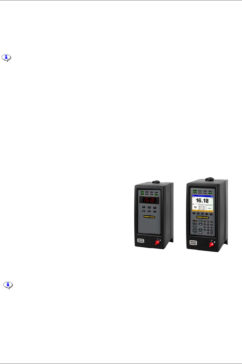
The
PF 4000 Graph has an easy-to-read LCD colour
display. Statistical data is collected, analysed and
presented on the screen. Changes and trends in the
assembly process are indicated by diagnostics and
statistical alarms, such as SPC monitor charts and
capability (Cpk) alarms. Alpha-numeric keys allow on-
unit setup and easy checking of traces and statistics. PF
4000 Graph model has a very compact design, and a
standardized mounting plate ensures easy installation
at every workstation.
Completing the range, the
PF 4000 Compact has a basic
operator interface with six-button keyboard and LED
display. Pre-programmed using ToolsTalk PF and with
a PC as the interface, it offers the same functionality as
the Graph model.
See the
PF 4000 ASL (9836 3113 00) for
technical data, dimensions drawings,
connections and spare part list.
PF 4000 Compact
PF 4000 Graph
9836 3123 01 15 (330)

Introduction to Power Focus
16 (330) 9836 3123 01
3.1.1 Logic Configurator
Power Focus 4000 has an integrated Logic Configurator. This provides limited PLC functionality as an
integrated part of the controller, without additional hardware components. It is possible to configure
specific “PLC style” signal flow between the line or the fixture and the PF 4000. For more information see
chapter
Logic Configurator.
3.1.2 SynchroTork
Available in the Power Focus 4000, SynchroTork allows continuous synchronisation of up to six spindles
during final tightening. This will improve assembly quality in the joints where an even clamp force build-
up is critical, such as in U-bolt applications. The torque difference between the spindles is minimised
during the tightening stage by adjusting the individual speeds.
Synchronisation of the tools is assured through high-speed communication via the proprietary Power
Focus accessory bus. It should be noted that this function does not eliminate the need for a reaction bar, or
similar, in higher-torque applications.
3.1.3 Yield control
With the Power Focus 4000 is it possible to apply a Yield control strategy for the cases where to get the
most out of the fastener. While maintaining productivity, the operator can make the fixtured tool shut off
where each individual bolt yields, and not based on a firm torque or angle value.
See function description for Yield control in section
Control strategies.
Introduction to Power Focus
3.2 PF 3000/3100/3102
The PF 3000 is a control system for Atlas Copco Tensor S and DS tools. PF 3100 is a control system for
Atlas Copco Tensor ST tools (including functionality for S and DS tools).
PF 3102 is the control system
for Atlas Copco Tensor SL tools.
Tensor STB tools require a communication kit to work with Power Focus 3100. The kit
consists of a serial port adapter (access point), cable connector (supplies the serial port
adapter with power). For more information see chapter
Tensor tools .
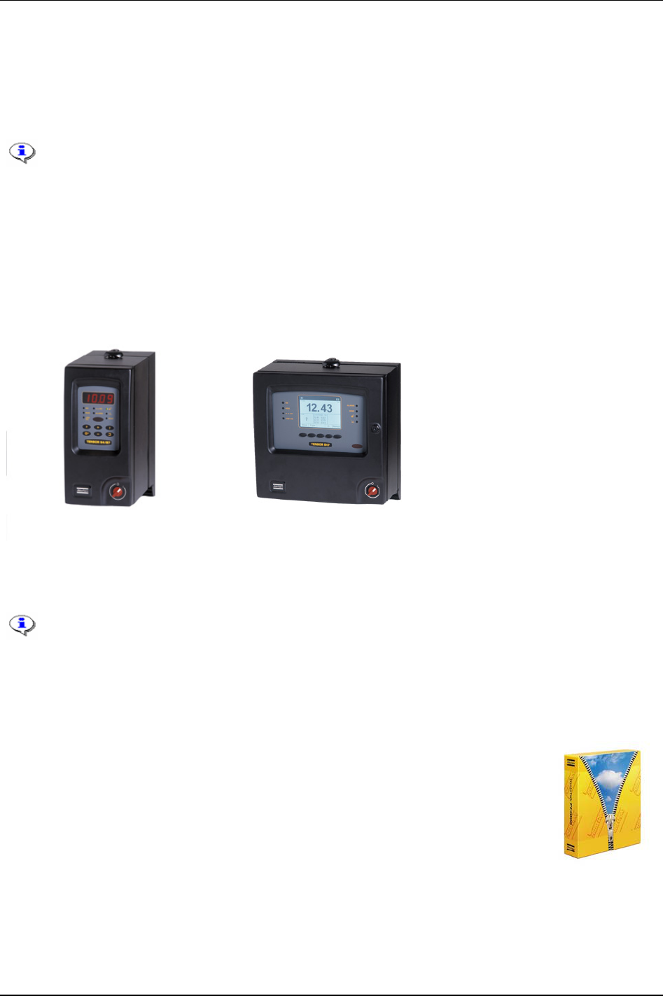
Two different hardware units are available, Graph and Compact.
PF 3000 Compact offers minimum hardware expenditure and is easily stackable for multiple tool
configurations.
PF 3000 Graph models offer full stand-alone programming via an integrated keyboard and
large display located on the front panel of the unit. PF Graph can also be used as a terminal for one or
more PF Compact controllers.
PF 3000 Compact PF 3000 Graph
See the
PF 3000 ASL (9836 2156 01) for technical data, dimensions drawings, connections and
spare part list.
For PF 3102 controllers (SL tool drivers) only the Compact model is available.
3.3 ToolsTalk PF
ToolsTalk PF, a PC software package developed by Atlas Copco, offers easy and user-
friendly programming and real time monitoring of Power Focus units. ToolsTalk PF is
based on extensive experience and thorough analysis of existing manufacturing
industry needs.
ToolsTalk PF can be installed on standard PCs running Windows 2000 or XP and communicates with PF
via the serial port or via Ethernet TCP/IP. The real time monitoring functions include access to Cpk,
Traces, Operator monitor, etc.
9836 3123 01 17 (330)

Introduction to Power Focus
18 (330) 9836 3123 01
3.4 ToolsNet
ToolsNet is a part of the ATS (Assembly Tools Software) that works together with PF to complete the
tightening process.
ToolsNet works together with the controllers and the selected database, MS SQL Server or Oracle to
collect, store and visualise all historic tightening-related data. ToolsNet allows the user to get reports on
shifts, lines, individual vehicles or controllers for process improvement purposes. All the reports can
easily be exported to Excel.
ToolsNet can be used as a standalone product or together with the other modules from the ATS. ToolsNet
as a standalone product:
Tightening data collection and storage in a standard database management system (ORACLE or MS
SQL Server).
Web based reporting interface with standard reports, statistical information and graphs.
Process improvement through extensive statistical process control functionality.
Full traceability of every tightening done with a connected controller.
ToolsNet with Factory Overview:
All functionality as a standalone product.
Factory Overview integrated with ToolsNet - Right-click in Factory Overview to get web reports from
ToolsNet.
ToolsNet with Event Monitor:
All functionality as a standalone product.
Event history in ToolsNet reports.
3.5 Factory Overview
Factory Overview is a part of the ATS (Assembly Tools Software) that works together with PF to complete
the tightening process. Factory Overview is the portal to the tightening process. It visualises the whole
process and makes it possible to monitor all tightening applications from one central place.
Factory Overview can be used both as a standalone product and together with the other modules from the
ATS.
Factory Overview as standalone product:
Graphic overview of tightening status for each controller.
Displays inactive and disconnected controllers.
Direct program control from controller icons together with ToolsTalk PF.
Factory Overview with Event Monitor:
All functionality as a standalone product.
Graphical overview of event status for each controller.
Direct access to event list from controller icons.
Factory Overview with ToolsNet:
Full functionality as a standalone product.

Introduction to Power Focus
Right-click controller icons to view controller’s spindle reports with tightening results.
3.6 Event Monitor
Event Monitor is a part of the ATS (Assembly Tools Software) that work together with PF, ToolsNet,
Factory Overview and the API to complete the tightening process. Event Monitor offers real-time event
reporting from the controllers in a centralised and filtered format.
Event Monitor can be used both as a standalone product and together with the other modules from the ATS.
Event Monitor as a standalone product:
Centralised real-time notification of events, plus a list of the 1000 latest events from all connected units.
Ability to filter the information to suit the user.
Ticketing functionality with comments that can eliminate double work and allows the storing of
comments for future reference.
Web based Java application, easy access from any PC without installation overhead.
Event Monitor with Factory Overview:
Full functionality as a standalone product.
Event status shown for each controller icon as it is reported from the Event Monitor server to the Factory
Overview.
Right-click controller to get a snapshot of the recent events for that controller.
Event Monitor with ToolsNet:
Full functionality as a standalone product.
One database for tightening results and event history offers powerful reporting possibilities.
3.7 API
The API (Application Programmers Interface) is an interface to the Power Focus system that enables users
to access data in PF from custom-made applications.
The Power Focus API is a software library that serves as the interface between the custom application and
the PF. This means that it exports a number of objects and methods that the custom application can access
in order to manipulate the PF without needing to know the details on how the actual communication is
done. The Power Focus API handles all necessary communication between the PC on which the custom
application is installed, and the specific PF involved. The developer of the custom application needs only
to know which objects and function(s) to access, and in some cases how the returned data is formatted.
3.8 RBU
RBU (Rapid Backup Unit) unlocks a specified level of functionality and acts as a back-
up unit for the configuration of PF. There are different types of RBU; gold, silver,
bronze, X (for ETX tool functionality and DS (for Tensor DS tool functionality). The
RBU gold unlocks the full capacity and functionality of the Power Focus. Combine the
RBU giving the required functionality with the chosen hardware.
When a RBU is plugged in to an empty PF, the RBU configuration is transferred to the controller. This
allows the quick installation and replacement of controllers on the assembly line.
9836 3123 01 19 (330)
Introduction to Power Focus
3.9 Cell
A key word in the Power Focus concept is Cell. This means that one PF Graph can monitor and control up
to 19 PF Compact controllers (for a total of 20 units), which saves space and hardware cost. Each Cell can
be connected to the plant’s network via the built-in Ethernet port, and results from the units can be
monitored via the Atlas Copco ToolsNet server.
3.10 Job
By scanning the bar code on an object on the assembly line, Power Focus automatically selects the correct
parameters. This is one example of the
Job function. When all fastenings at one station have been
performed, the operator on the line is given an overall JOB OK (“Station OK”) signal. Several PF units
can be linked together via the network to create a Cell Job, issuing an OK signal when all units in one
Cell have completed their tightenings.
3.11 Sync
Up to 10 synchronised spindles can be setup within one Cell. This function is called Sync. A single start
signal starts all tools and a “Sync OK/NOK” is reported, as well as individual tool results. Step-by-step
configuration and setup makes it easy to modify and to re-use installed equipment.
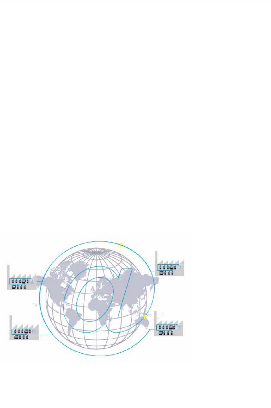
3.12 Communication
Built-in communication provides efficient use of modern communication technologies with Atlas Copco
products. The Power Focus system can be built to suit the user’s needs, from a simple system offering
many functions, to a complete factory system. Using open standards like TCP/IP, it is possible to connect
and communicate with external systems and allows global communication.
Communicate with one PF at a time via the serial connection or with a complete network of PF units via
the built-in TCP/IP connection.
Power Focus communicates with a range of accessories via the internal I/O bus. PF units and accessories
20 (330) 9836 3123 01

Introduction to Power Focus
can be combined according to the customer’s requirements.
The Power Focus can be configured to communicate via the most common buses on the market; ProfiBus,
DeviceNet, InterBus, etc. Real time communication is done over a proprietary I/O bus for tool
synchronisation. Several outputs can be activated for communication with PLC’s and other external
equipment. Each PF has four relay contacts, four optic isolated inputs and a 24 V DC / 1 A internal power
supply for external control circuits. All inputs and outputs can be configured using the ToolsTalk PF
software. The number of digital inputs and outputs can be increased using an I/O Expander on the I/O
bus.
With Power Focus, full networking capability is available in the controller as an integrated function, in
relation to both hardware and software. ToolsNet is Windows NT compatible, which offers easy to use,
effective database and data collection functions, using standard databases like SQL, Oracle and Microsoft
Access. PF can be connected to a network for central programming and data collection using ToolsNet.
With the modular concept, the Power Focus is the building block used to create complete and cost
efficient solutions that satisfy the various needs of modern industrial assembly operations.
3.13 Accessories
The Power Focus concept features a number of accessories that simplify the guidance and follow-up of
performed tightenings. The accessory functions can be set up using ToolsTalk PF or a PF Graph unit.
The benefit of using serial bus-based accessories (
I/O bus) is that they can be connected in series, from
accessory to accessory rather than hard wiring each accessory to the Power Focus. This arrangement increases
flexibility and affords quick installation.
Power Focus uses 24 V DC, 1 A to power the bus, which is also used to power external I/Os. If more current
is needed, the bus must be powered externally. Every device has a 24 V DC input for this purpose.
The
I/O Expander enables the connection of several inputs and relays when more
than those built-in are required. There are 8 inputs and 8 relays with the same
functionality as the four built-in I/Os. Each input and relay can be configured
individually.
The
Socket Selector is a socket tray with LED’s that can be used to guide the user
through a Job sequence. When using more than one Pset it is very convenient to
use a selector. When a socket is lifted, the corresponding Pset will be selected.
There are two different types of Socket Selectors, selector 4 and selector 8, the
only difference being that selector 4 has four sockets and selector 8 has eight
sockets. The Socket Selector is also communicating on the I/O bus.
The
RE-Alarm gives status information to users using lights and/or audible signals.
The RE-Alarm is connected to the Power Focus on the I/O bus. The RE- alarm is
configured in the Power Focus and it is possible to configure the information.
9836 3123 01 21 (330)
Introduction to Power Focus
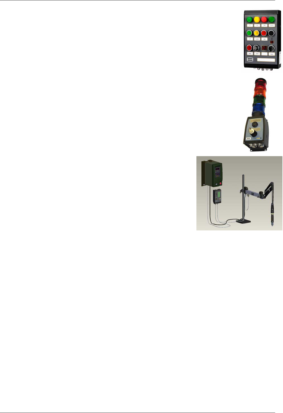
The Operator Panel is an external device for the PF. It is a general purpose lamp- and
switchbox, replacing the customer specials that are made today. The Operator Panel
communicates directly with Power Focus and the device configuration is made in ToolsTalk
PF.
See the
Operator Panel user guide (9836 2456 01) for more information.
The StackLight is a flexible light and switch device for Power Focus, PulsorFocus,
PowerMacs and Tensor DS/DL Advanced tightening controllers.
See the
StackLight user guide (9836 2642 01) for more information.
The
Tensor Tracker Arm SL is the latest generation of intelligent torque
reaction arms that add new features to screwdriver technology. In
conjunction with
PF 3102 controller and monitoring system for advanced
tightening technology it represents a new step in productivity and quality
assurance.
See the Tensor Tracker SL user guide (9836 2466 01) for more information.
22 (330) 9836 3123 01

Introduction to Power Focus
3.14 Nutrunners
Atlas Copco’s Tensor STB heralds a new generation of transducerised nutrunners in the Tensor family.
STB tools communicate with the
PF 4000 and PF 3100 tightening controller systems through wireless
digital communication, built on IRC (Industrial Radio Communication) technique.
Tensor ST nutrunners communicate with PF 3100 controllers through digital communication, allowing
new tool features and greater flexibility due to not so many wires and leads. Compared with a Tensor S
tool, it is also lighter with improved accessibility.
Atlas Copco’s
Tensor SL is a range of low torque transducerised tools based on Tensor ST technology. SL
tools communicate with the SL driver,
PF 3102, digitally. The controller is used with low voltage SL
tools.
Atlas Copco’s
Tensor S, running on PF 3000/3100 controllers, are available in four different
configurations; fixture, pistol grip, straight and angle application. The three motor types are designated
S4, S7 and S9, indicating different motor outputs and speeds. The tools can be combined in various
models to meet a variety of requirements within the industry. Fixtured applications can easily be installed
and integrated with standard Atlas Copco components.
The ultra-compact
ETX tool is designed for fixtured applications, optimised for extreme functionality,
durability and flexibility. Controlled by
PF 3100 and featuring a “smart” memory chip calibration and
service data. The ETX combines the same advanced control, monitoring options and high productivity as
the Tensor S/ST range, with the bonus of a reduced space requirement and extended spindle durability.
Atlas Copco’s
Tensor DS tools, running on PF 3000/3100 controllers, have no transducer. Instead of
receiving an electrical signal from a strain gauge, the tool derives the torque from several relevant
parameters, such as voltage, speed, temperature and current. The DS tool is proven to achieve excellent
repeatability. However, the operating range is smaller than for a Tensor S tool, and the user might need to
adjust the torque measurement for each Pset and joint for greater accuracy.
An
Open end tool (or tube nut tool) is a Tensor S or ST tool equipped with an Open ended head. It is used
to tighten nuts on tubes and similar applications.
For more tool related information, see chapter
Tensor tools.
3.15 ACTA 3000
An ACTA 3000 performs a full range of functions, from simple torque checks
to advanced graphic tightening analysis. It comes in different models and it is
easy to upgrade.
ACTA 3000 measures torque, angle and pulses and facilitates the conduction
of statistical analyses of the tightening process. An ACTA 3000, together
with the ToolsTalk ACTA PC utility, is a complete SPC tool. Furthermore, it
has a reminder function to notify the user when calibration and maintenance
are due.
9836 3123 01 23 (330)

Getting started with ToolsTalk PF
4 Getting started with ToolsTalk PF
ToolsTalk PF is an application that acts as an interface between the user and the Power Focus. It is used
for programming and monitoring Power Focus from a PC.
With ToolsTalk PF installed, users can communicate with the Power Focus via the serial port (RS232) as
well as over the Ethernet.
Ethernet communication makes the management of Power Focus easy and efficient, since ToolsTalk PF
can be installed on a PC anywhere on the network.
ToolsTalk PF serves as an interface between the user and PF. With ToolsTalk PF, users can create and
edit instructions and settings for the controller. The settings needed to control the tightening process
performed by the Power Focus include; tightening strategies, control parameters, torque parameters,
angle parameters, speed and ramp parameters and time parameters.
The settings are transferred to Power Focus via an Ethernet connection or via the serial port. Process data
can be collected from the Power Focus and monitored in real-time. ToolsTalk PF makes management of
Power Focus easy and efficient, since the software can be installed on any PC on the network.
ToolsTalk PF is fully compatible with Microsoft Windows and supports widely accepted communication
protocols such as; Ethernet, TCP/IP and RS232 (serial communication).
ToolsTalk PF is easy to install:
Insert the installation CD.
Run
Setup.exe and follow the on-screen instructions.
Open ToolsTalk by selecting
Start -> Program -> Atlas Copco Tools AB ->
ToolsTalk Power Focus.
Select between a free trial version for 60 days (demo) or register by enter
installation and license number. Contact your locally Atlas Copco representative
for information how to get the license number.
The software can be registered on the Atlas Copco Tools web site at
http://www.atlascopco.com/tools/software.
9836 3123 01 25 (330)
Getting started with ToolsTalk PF
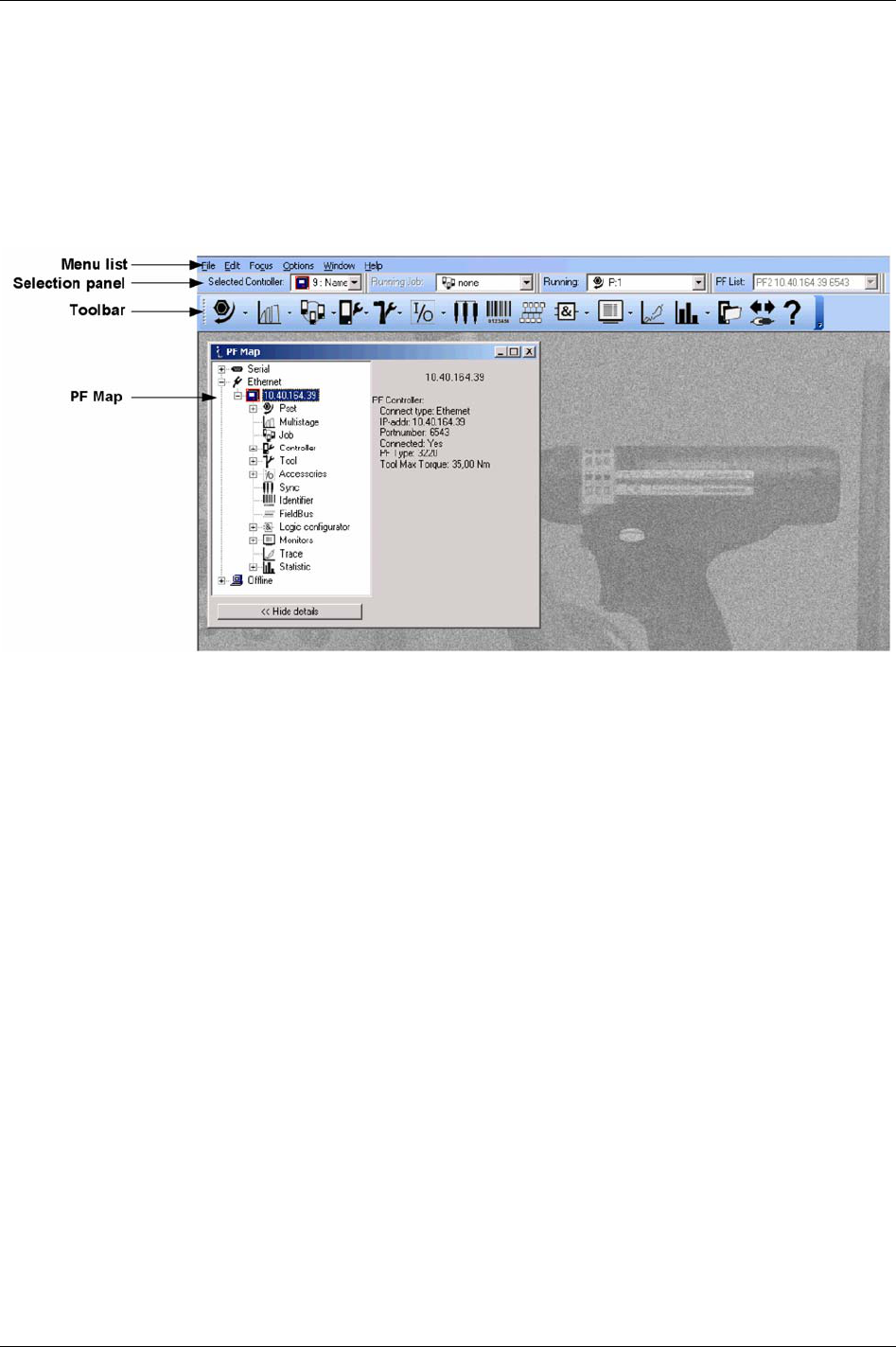
4.1 Overview
Almost every function in ToolsTalk PF has its own window. The figure below shows the ToolsTalk PF
interface with menu list, selection panel, toolbar and PF Map.
There are several ways to start a function in ToolsTalk PF. With almost all functions it is possible to use a
menu item in the menu list. Click on a symbol in the toolbar or double-click on the text in the PF Map.
26 (330) 9836 3123 01
Getting started with ToolsTalk PF
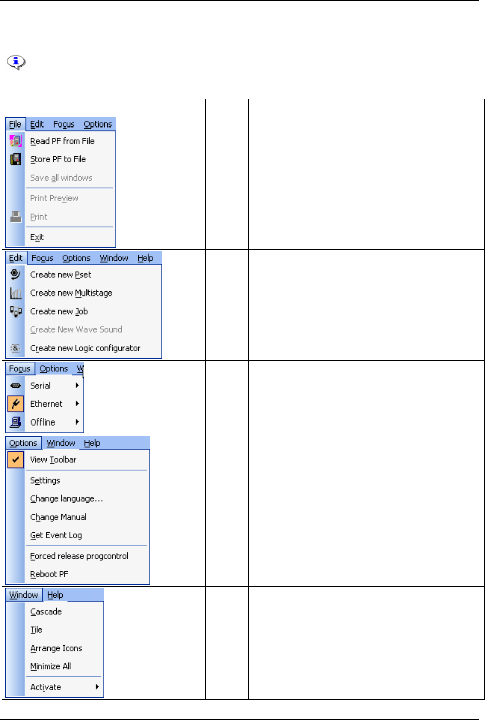
4.1.1 Menu list
An additional menu appears in the Menu list when opening a function window. For example,
when opening a Pset window, a new menu named “Pset” will appear in the menu list.
Illustration Name Description
File Read and store files, print and exit ToolsTalk PF from the File
menu.
Edit Create a new Pset, Multistage, Job Wave sound and Logic
Configurator from the Edit menu.
Focus The Focus menu specifies the type of connection to use when
connecting to the Power Focus. Choose between an Ethernet
connection and a Serial connection.
The Offline mode allows access to ToolsTalk PF without the
need for a connection to a Power Focus.
Options From the Options menu it is possible to select whether the
toolbar will be shown or not. The following functions are also
available; Settings, Change language, Change manual, Get
event log, Forced release progcontrol and Reboot PF.
Window Set properties for windows and icons from the Window menu
as well as enable and open the Activate menu.
9836 3123 01 27 (330)
Getting started with ToolsTalk PF
Activate The Activate menu contains a list of all available functions
(Pset, Job, Multistage, etc).
Help The Help menu allows access to the Power Focus help file.
About ToolsTalk PF brings up details about the version of the
ToolsTalk PF program in use.
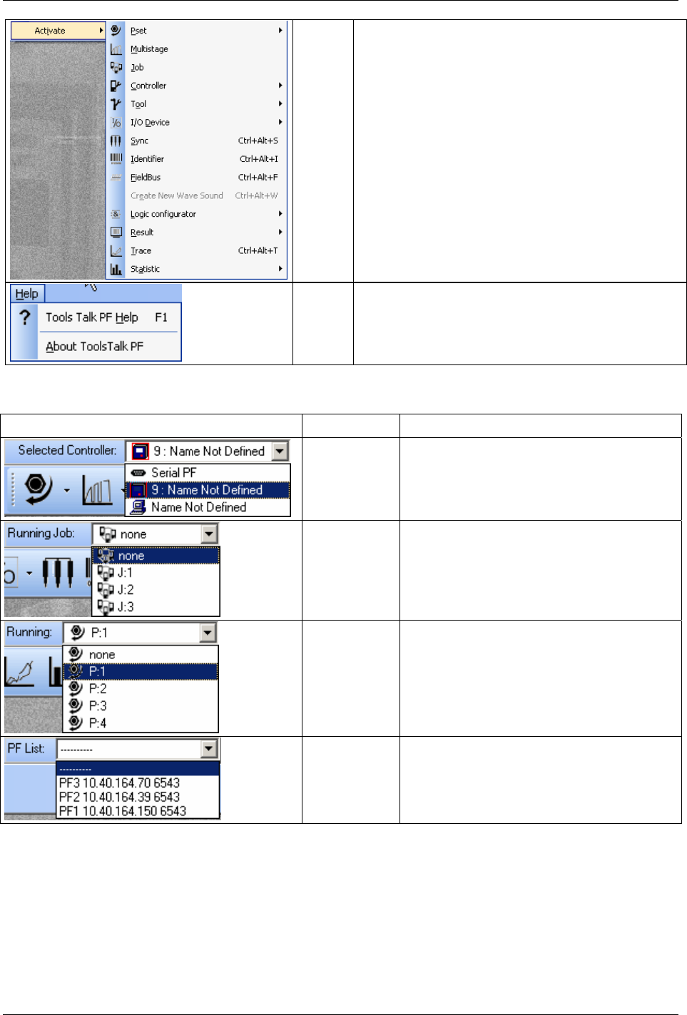
4.1.2 Selection panel
Illustration Name Description
Selected
Controller
The available options are; Serial connection,
Ethernet connection and Offline mode.
Running Job If parameter
Job select source [C201] is set to
“Ethernet/serial”, it is possible to select a Job to run.
Running
Pset/Multistage
If parameter Pset select source [C200] is set to
“Ethernet/serial”, it is possible to select a Pset or
Multistage to run.
PF List To simplify the Ethernet connection to a Power
Focus use the combo box PF List. Select an item in
the combo box and ToolsTalk PF will connect to the
corresponding Power Focus. The information in the
list contains; name, IP address and port number.
28 (330) 9836 3123 01
Getting started with ToolsTalk PF
4.1.3 Toolbar
Icon Icon name Description
Pset This icon opens the programming window for the first Pset.
Click on the arrow to the right to select between existing Psets (shown along with number
and name). The list can contain a maximum of 250 Psets.
Use the function in the PF Map to create a new Pset.
Multistage This icon opens the programming window for the first Multistage (if any).
Click on the arrow to the right to select between existing Multistages (shown along with
number and name).
Use the function in the PF Map to create a new Multistage.
Job This icon opens the programming window for the first Job (if any).
Click on the arrow to the right to select between existing Jobs (shown along with number
and name).
Use the function in the PF Map to create a new Job.
Controller This icon opens the first part in the Controller programming section.
Use the arrow to the right to select between all section (Information, Configuration,
Network, COM ports, Display, Memory and Accessibility).
Tool This icon opens the first part in the Tool programming section.
Use the arrow to the right to select between all section (Information, Configuration,
Diagnostic and Maintenance).
Accessories This icon opens the first part in the Accessories programming section.
Use the arrow to the right to select between all section (Digital I/O, I/O bus, Tool bus and
Printer).
Sync This icon opens the Sync programming section.
Identifier This icon opens the Identifier programming section.
Field bus This icon opens the Field bus programming section.
Logic Configurator This icon opens the programming window for the first Logical configurator (if any).
Click on the arrow to the right to select between existing Logical Configurators (shown
along with number and name).
Use the function in the PF Map to create a new Logical configurator.
Monitors Click on the arrow to the right of this icon to select an appropriate monitor; Result monitor,
Job monitor, Operator monitor, Identifier monitor and Get all results.
Result monitor is a convenient way to monitor the tightening status.
Trace Click the Trace icon to bring up a graphical display of the tightening results.
Statistic Click on Statistic icon to display statistical results and graphs. Via the arrow to the right it is
possible to select a statistic to run.
PF Map This icon opens the PF Map if it is closed.
Connect The Connect icon changes appearance depending on the connection status. When the PC is
not in contact with the Power Focus, this icon is visible. Clicking on it will establish a
connection between the PC and the PF. Choose connection in “selected controller” list
(ToolsTalk PF menu list).
9836 3123 01 29 (330)
Getting started with ToolsTalk PF
Icon Icon name Description
Disconnect Once a connection is established this icon will appear. Clicking on it will Disconnect the PC
from the PF.
Help This icon opens the Help section.
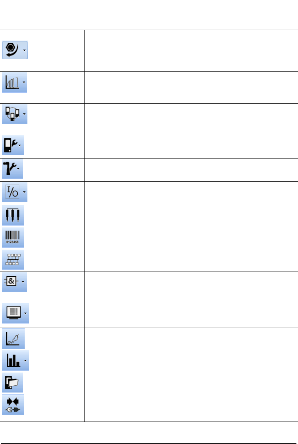
4.1.4 PF Map
The PF Map gives an overview of and shortcuts to all settings in ToolsTalk PF. Click on the minus or plus
symbols to open and close menus and double click on function names (Pset, Multistage, Job, etc) to open
the corresponding function. Brief information about the selected setting is displayed in the right panel of
the PF Map.
Right-click the function names to create a new instance of the function.
30 (330) 9836 3123 01

Getting started with ToolsTalk PF
PF Map
function
Description
Pset A Pset contains all the necessary information Power Focus needs to perform a tightening. There are a number of
parameters included in a Pset, among them; control parameters, torque parameters, angle parameters etc.
See chapter
Pset for more information.
Multistage In some instances it is necessary to perform a tightening in several stages. These circumstances require specific
tightening strategies. Multistage allows the user to create linear sequences of up to eight Psets to perform a
tightening divided into stages.
See chapter
Multistage for more information.
Job A Job is a collection of Psets or Multistages, which are useful when performing several multiple tightening
operations, each with different requirements. This is convenient since the operator does not have to select a new
Pset or Multistage for every tightening.
See chapter
Job for more information.
Controller Controller contains information and settings for the PF. This includes network, COM ports, display, memory and
accessibility.
See chapter
Controller for more information.
Tool The Tool branch includes information, configuration, diagnostic and maintenance for the Tensor tool connected
to the PF.
See chapter
Tool for more information.
Accessories In the Accessories branch are the digital inputs and outputs of the PF configured and diagnosed. It also includes
information about the devices connected to the I/O bus and tool bus, and how to configure these devices.
See chapter
Accessories for more information.
Sync Up to ten PF units in the same logical Cell can be synchronised to perform the same task simultaneously, a
function known as Sync. This type of operation requires the Synchronisation of the Power Focuses involved.
With this tool Sync parameters can be created.
See chapter
Sync for more information.
Identifier It is possible to send an Identifier string to a PF. This string is normally generated by a barcode reader connected
to one of the serial ports on the PF (this barcode is in car plants usually known as a VIN or ESN).
See chapter
Identifier for more information.
Field bus Field bus communication is useful for data communication between the PF and PLC’s. It is an effective and fast
way for the data transfer of short data packages.
See chapter
Field bus for more information.
Logic
Configurator
The Logic Configurator functionality is only available for PF 4000.
The ToolsTalk PF software feeds the PF 4000 controller with inputs, called Logical sets. The Logical sets consist
of a Relay status array and a DigIn status array, The arrays have the status of each relay/digital input function (if
the function is defined on the internal I/Os or one of the I/O Expanders).
Every Logic Configurator circuit instruction list is evaluated every 100 ms which corresponds to a tick or every
time an input status changed.
See chapter
Logic Configurator for more information.
Monitors ToolsTalk PF provides a number of monitors designed to present extensive information about the various
functions of Power Focus (Result monitor, Job monitor, Operator monitor, Identifier monitor and Get all results).
Result monitor is a convenient way to monitor the tightening status.
See chapter
Monitors for more information.
Trace Via the Trace function it is possible to view tightening graphs with different display settings.
Select which type of chart to view; Torque over time, Angle over time, Speed over time, Torque and angle over
time, Torque over angle, Torque and Speed over time.
See chapter
Trace for more information.
Statistic The Statistic displays statistical results and graphs.
See chapter
Statistic for more information.
9836 3123 01 31 (330)
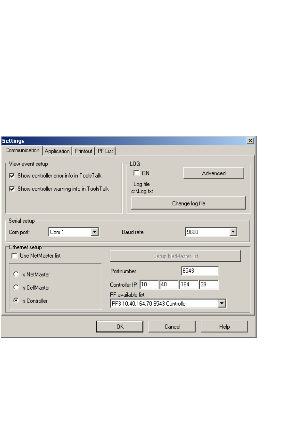
Getting started with ToolsTalk PF
4.2 Settings
The Settings dialog box has four tab sheets:
Communication and connecting an installation.
Setup for viewing information inside the ToolsTalk PF
Application.
Printout setup.
PF list administration.
4.2.1 Communication
The Communication tab sheet has four sections; View event setup, Serial setup, Ethernet setup and LOG.
32 (330) 9836 3123 01
Getting started with ToolsTalk PF
The
View event setup field contains selections for viewing controller errors and warnings.
Under
Serial setup it is possible to select which Com port to use (normally Com1 or Com2). The Baud rate
can be set to 2400, 4800, 9600, 19200, 38400, 57600 or 155200.
All connected PF units need the same baud rate value in order to be able to work together.
The default value is 9600.
Under
Ethernet setup select the type of connected Power Focus (Net reference, Cell reference or
Controller. Also set the Port number and Controller IP address. The default Port number value is 6543. If
using an item from the PF list (PF available list) then all three parameters (type, port, IP) will be set
simultaneously.
To edit Ethernet setup parameters, ToolsTalk PF has to be in disconnected mode.
In the
LOG section it is possible to enable the log function for communication between Power Focus and
ToolsTalk PF. If Log is set to “On”, then messages will be stored in a file. The file name is stated in the
log file field. Create rules for logging by clicking the
Advanced key.
If
Split log in the Advanced log settings is activated the size of “log.txt”- file cannot exceed the value set
in
Logfile size. When the file is full the program will copy the contents to a file called “log~.txt” and erase
the content of “log.txt”. Data will then continue to be stored in “log.txt”.
With the additional software application Tool User Administration (TUA) it is possible to
log specific user information. The user operations in ToolsTalk PF (i.e. changing of
parameters in Config or creating of Psets), together with user name and date can then be
included and stored in the log file. Furthermore, TUA offers the configuration of user
group accessibility.
9836 3123 01 33 (330)
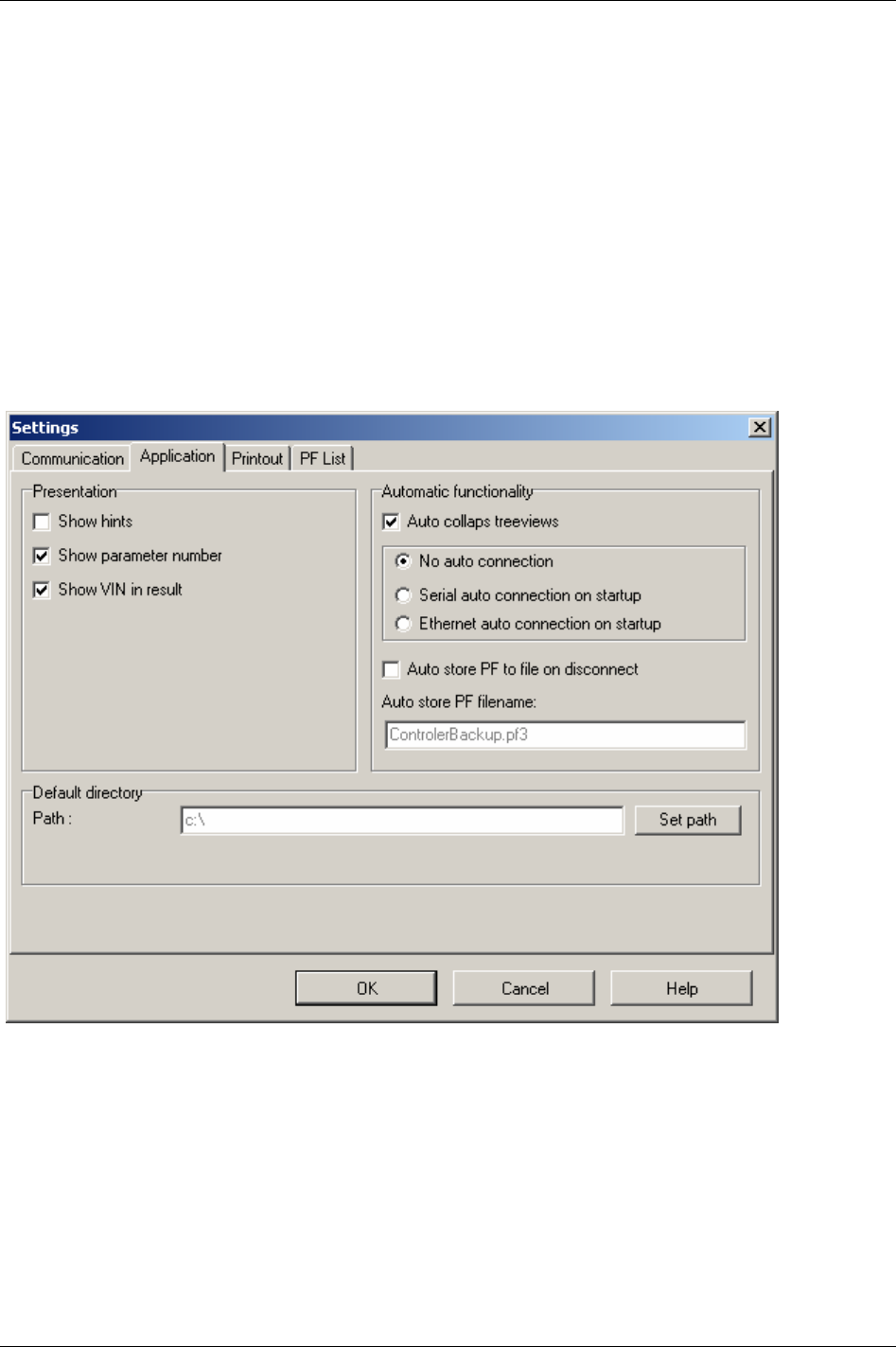
Getting started with ToolsTalk PF
4.2.2 Application
The Application tab sheet has three sections; Presentation, Automatic functionality, Default directory.
The first section concerns the ToolsTalk PF
Presentation for programming windows. Use this to view
hints and parameter numbers.
The first checkbox in
Automatic functionality activates/deactivates Auto collapse tree views. If
Serial/Ethernet auto connection on start-up is checked, ToolsTalk PF will try to connect to the Power
Focus via serial/Ethernet communication immediately on start-up. If the Auto store PF to file on
disconnect box is checked, ToolsTalk PF will store the PF to file when disconnecting.
The last field allows the path to be set for the
Default directory. Log files and auto stored PF files will be
saved to the selected default directory.
34 (330) 9836 3123 01
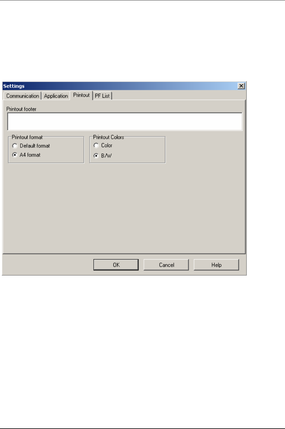
Getting started with ToolsTalk PF
4.2.3 Printout
The Printout tab sheet contains details of printout settings.
If a text is entered in the
Printout footer it will then appear on every printed paper.
If using the A4
Printout format, select A4 format, otherwise select default format.
Section
Printout colours is only applicable for colour printers.
9836 3123 01 35 (330)
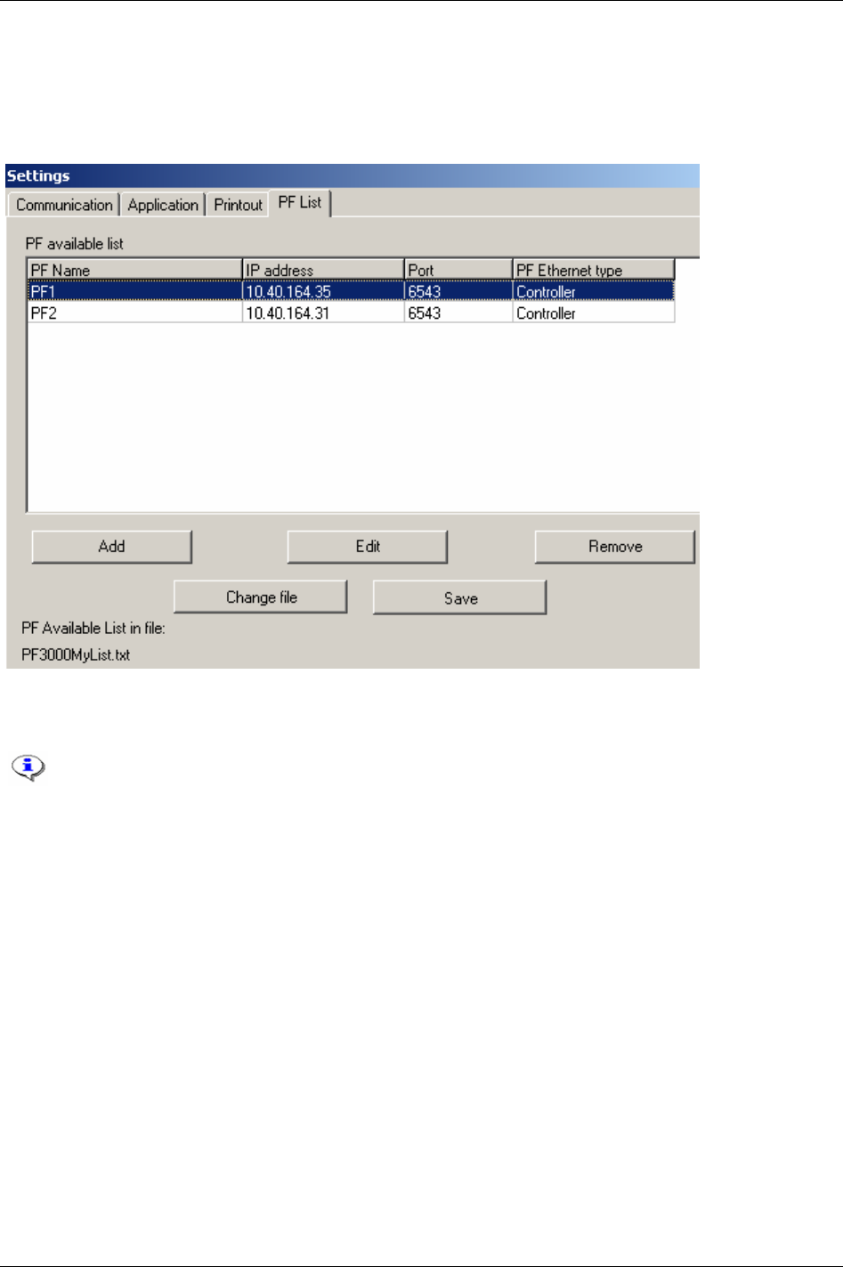
Getting started with ToolsTalk PF
4.2.4 PF List
The PF List tab sheet manages the PF available list. Add, modify and remove items from here. An item is a
PF with name, IP address and port number and controller type.
4.3 Connecting a PF
There are different types of connections possibilities; Ethernet TCP/IP, Serial RS232 and
USB. USB connection is only available for PF 4000.
4.3.1 Ethernet connection
From the Options menu, open the Settings dialog box.
Type
Controller IP address to establish a Power Focus connection.
Also specify whether the Power Focus is a
Net reference, Cell reference or a Controller (see chapter
Controller).
Click
OK.
When connecting a Cell reference or Net reference a list of all Power Focus (Controllers/Members) in the
Cell/Net appears.
To connect to a Controller, double-click on a PF in the PF Map.
36 (330) 9836 3123 01

Getting started with ToolsTalk PF
4.3.2 Serial connection
When using the serial connection, it is important to use the proper baud rate settings. In
order to establish a connection between ToolsTalk PF and the PF they must use the same
baud rate. The default baud rate is set to 9600 bit/s.
Change the Baud rate in the
Settings dialog box (from the Options menu).
Make sure that the serial cable is connected to the correct
Com port on the PC.
4.3.3 USB connection
An USB port is standard on PF 4000. The port is located on the PF front panel.
Connect an USB cable between PF and the computer/laptop (PF acts USB device).
An extra COM port should now be visible in computer/laptop.
Open ToolsTalk and connect serially via the extra COM port.
4.3.4 To connect
There are several ways to connect a Power Focus from ToolsTalk PF:
Select
Focus in the Menu list and then choose between Serial connection and Ethernet connection.
In the drop menu for
Selected controller in Selection panel, click on either Serial PF or Ethernet PF.
In the
PF Map, double-click on the controller under Serial PF or Ethernet PF.
Use the
Connect icon on the Toolbar. By default this icon will make a serial connection. However, it
remembers the most recent connection.
Use predefined PF units from the
PF List in the Selection panel.
4.3.5 To disconnect
To disconnect, click on the Disconnect icon on the Toolbar or select Disconnect in the Menu list (Focus ->
Ethernet/serial -> PF name -> Disconnect).
4.4 Storing programming on file
To store the programmed settings on file, open the File menu. The following options are available:
Read <object>
Read PF from File
Save <object>
Store PF to File
<Object> could be a section in the PF Map, for instance in Pset, Multistage, Job, Controller, Tool, Sync,
Identifier, Field bus, Trace or Diagnostic.
See table below for option descriptions.
9836 3123 01 37 (330)
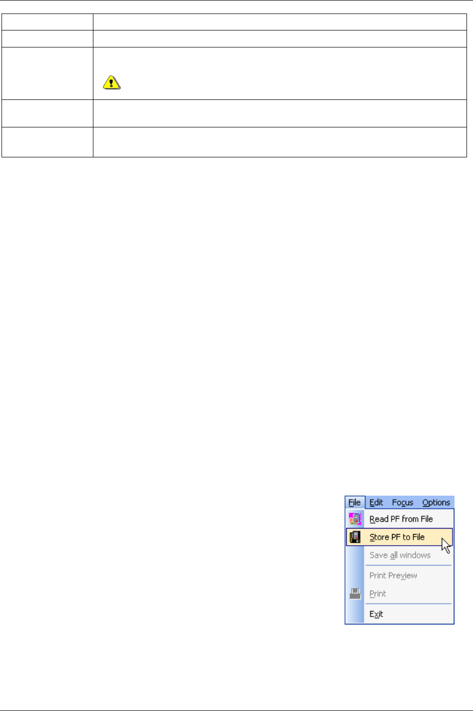
Getting started with ToolsTalk PF
Option Description
Store PF to File Programmed settings in the Power Focus will be stored to a file when connecting to a Power Focus.
Read PF from File The Power Focus updates with programmed settings stored on file when connecting to a Power Focus
and performing Read PF from file.
Read PF from file will overwrite current programming and configuration in the
connected PF.
Save <object>
(Config, Pset, Job etc.)
This function stores a single object to file. The selected window in ToolsTalk PF will be stored to
file.
Read <object >
(Config, Pset, Job etc.)
This function writes a single object file to the Power Focus. The selected window will be updated
with data from the file.
When performing
Store PF to File, the user should name the file. ToolsTalk PF will store the programmed
settings for more than one file (for example one file for each Pset, Multistage and Job).
When storing
PF to file it is possible to store files in Excel format. Select Excel as file format in the Save as
dialogue. The overhead file will have the extension “pft”. Extensions for the other stored files will be “xls”.
4.5 Offline
Offline mode gives the user the opportunity to conduct programming and configuration, without a PF
connection. All programming will be stored to or read from a file. It is possible to copy this file to one or
more PF units.
There are three different ways to select the offline mode:
In the main Menu list, select Focus -> Offline.
In the Selected controller drop menu, select Offline.
In the PF Map, and double-click Offline.
The file can be located on the local hard drive, network, etc. There is a certain number of default files
supplied when installing ToolsTalk PF. Also, find these files separately on the ToolsTalk PF installation
CD-ROM. Depending on the RBU license level; just select the file to use. The different RBU types
correspond to the names of the default files (“DS.pf3”, “Gold.pf3”, “Silver.pf3” and “Bronze.pf3”). It is
a good idea to make a backup of these files.
To create a file, first connect (Serial or Ethernet) to a Power Focus and then
click
Store PF to File on the file menu. Name the file and store it in an
appropriate location.
Select a file with the same license level as the PF. ToolsTalk PF opens the
selected file and the user is able to change it.
It is possible to continue to change the content of a file with a higher RBU
license level, but when trying to use the file with a PF with a lower license
level a warning message is generated.
38 (330) 9836 3123 01
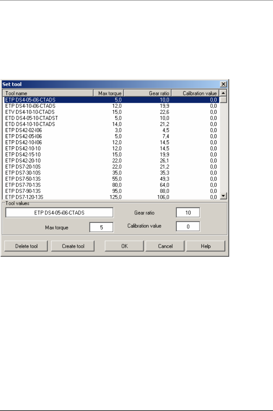
Getting started with ToolsTalk PF
4.5.1 Configuring a tool offline
Double-click Diagnostic in the PF Map.
Click
Set tool.
The Set tool window appears.
It is also possible to configure a new tool via the
Create tool key.
9836 3123 01 39 (330)

Pset
5 Pset
The set of parameters that controls the tightening process is contained within a so-called Pset.
This section describes how to setup the basic Pset parameters necessary to perform a
tightening. Create a Pset by using Autoset, quick programming or by setting the parameter
values manually using the PF Graph or ToolsTalk PF.
This section includes screenshots from ToolsTalk PF. The screenshots shows examples of
parameter settings and is NOT intended to be generally applicable. Check with your
local Atlas Copco reprehensive how to set up your specific system environment.
See chapter
Parameter list for a description of all available Pset options.
The basic Pset parameters are:
Control
Torque
Angle
Speed and ramp
Time
Batch count
Statistical
An easy way to program a Pset is to use the
Autoset function, see section Autoset. Enter a final target
torque value, perform a few tightenings and a new Pset is programmed. Power Focus adapts the
programming to the specific joint characteristics and sets all the parameters automatically. Autoset does
not change any parameters outside the used Pset.
Quick programming, see section Quick programming is, intended to help users to quickly configure a Pset
and gives the opportunity to use the Power Focus after a fast and simple programming. After completing
a quick programming procedure, the tool is ready to use for tightening to the set torque straight away. It
might be necessary to fine-tune some parameters in order to ensure smooth operation of the tool.
5.1 Create new Pset/Open Pset
In the PF Map, mark Pset, right-click
and select
Create New Pset.
Alternatively,
double-click on an
existing Pset to open the Pset
configuration window.
As default there is one Pset
existing in ToolsTalk PF.
9836 3123 01 41 (330)
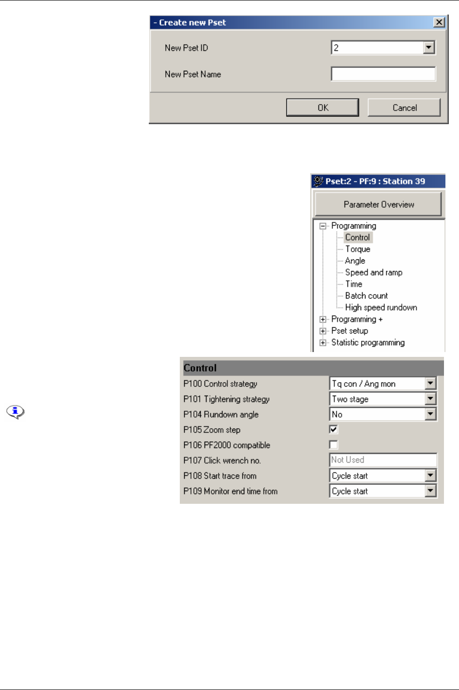
Pset
The Create new Pset window
pops up.
Select available
New Pset ID
from drop down menu.
Enter a
New Pset Name
(optional).
Click
OK to open the new Pset
setup window.
5.2 Programming
In the Pset setup window, expand the Programming branch.
Select
Control.
Choose the desired
Control strategy
[P100], Tightening strategy [P101] and
settings for the other parameters.
For strategy information, see
section
Control strategies and
section
Tightening strategies.
42 (330) 9836 3123 01
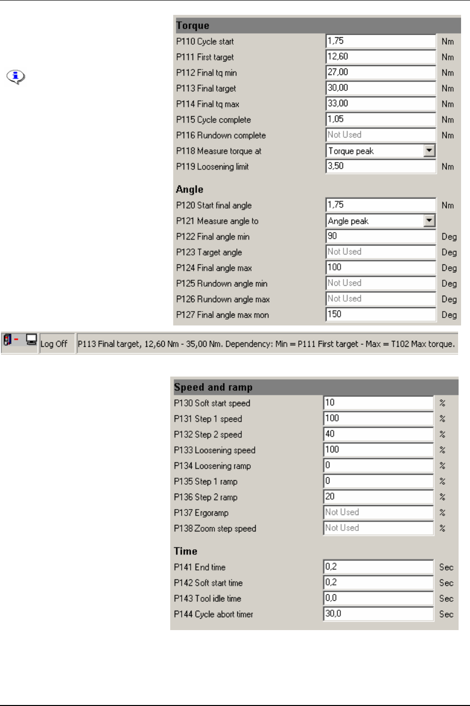
Pset
In the Pset Programming branch,
select
Torque or Angle.
Make suitable parameter settings.
By holding the cursor in
the respective parameter
box, the limits for each
parameter will be
displayed in the lower left
corner of ToolsTalk PF.
In the Pset
Programming branch,
select
Speed and ramp or Time.
Make suitable parameter settings.
9836 3123 01 43 (330)

Pset
In the Pset Programming branch,
select
Batch count or High speed
rundown
.
Make suitable parameter settings.
Click
Store to save the settings.
5.2.1 Control strategies
For all Tq con and DS con tightenings the process starts when the torque reaches Cycle start [P110] and ends
when the torque drops below
Cycle complete [P115] for a period of End time [P141] milliseconds.
For
Ang con and Reverse ang the tightening process also starts when the torque reaches Cycle start [P110].
For
Rotate spindle forward/reverse the tightening process starts immediately when the tool starts running.
For all these tightening strategies the tightening process ends when
End time [P141] milliseconds have
elapsed since
Target angle [P123] has been reached.
The
Target angle [P123] is defined by Measure angle to [P121] and can be measured from Start final angle
[P120] to Torque peak, Angle peak or Cycle complete [P115].
Final angle max [P124] is always evaluated from Start final angle [P120] to angle peak.
Tq con
The Tq con strategy controls the torque. This strategy is selectable for both one stage and two stage
tightenings. The tool stops when the torque reaches the
Final target [P113].
If, for some reason, the tool should exceed
Final tq max [P114], the tool shuts off and the (NOK) tightening
result is shown.
Tq con/ang mon
The Tq con/ang mon strategy controls the torque and monitors the angle. This strategy is selectable for
both one and two stage tightenings. The tool stops when the torque reaches the
Final target [P113] value.
If the tool for some reason should exceed
Final tq max [P114] or Final angle max [P124], the tool shuts off and
the (NOK) tightening result is shown.
Ang con/tq mon
Ang con/tq on strategy controls the angle and monitors the torque. This strategy is selectable for both one
and two stage tightenings.
Target angle [P123] is then defined as the number of degrees between Start final
angle [P120]
and angle peak. The tool stops at Target angle [P123].
If the tool for some reason should exceed
Final tq max [P114] or Final angle max [P124], the tool shuts off and
the (NOK) tightening results are shown.
44 (330) 9836 3123 01

Pset
Tq con/ang con (AND) / (OR)
The Tq con/ang con (AND)/ (OR) strategy controls both torque and angle. This strategy is selectable for both
one and two stage tightenings.
For
Tq con/ang con (AND), Power Focus controls the Final target [P113] value and the Target angle [P123]
value. The tool stops when both targets are reached. They do not have to be reached at the same time.
For
Tq con/ang con (OR), Power Focus controls the Final target [P113] value and the Target angle [P123]
value. The tool stops when the first of these two targets are reached.
For both
Tq con/ang con (AND) and Tq con/ang con (OR) the torque and the angle result must be within
respective min and max limit.
If, for some reason, the tool should exceed
Final tq max [P114] or Final angle max [P124], the tool shuts off
and the (NOK) tightening results are shown.
Reverse ang
The Reverse ang strategy reverses the spindle a specified number of degrees in the opposite tool tightening
direction. This is useful when, for example, the bolt needs to be loosened before the final tightening.
Create a Multistage to combine and perform several Psets as one.
Target angle [P123] is defined as the number of degrees between the Start final angle [P120] and the peak
angle. The tool stops at
Target angle [P123]. If the tool for some reason should exceed Final tq max [P114] or
Final angle max [P124], the tool shuts off and the (NOK) tightening results are shown. The torque value
shown in the result is torque at peak angle. Angle measurement starts when the
Start final angle [P120] is
reached.
For reverse ang, the “active” direction of the tool socket rotation is the opposite of the
Tool
tightening direction [P240]. For instance, to select “CW” turn the Direction ring to the left
position. For safety reasons, it is not possible to loosen the joint in this way.
Rotate spindle forward/reverse
The rotate spindle forward/reverse functions rotate the spindle a specified number of degrees, either
forward or reverse, independently of torque. The only torque values monitored are
Final tq max [P114] and
Final tq min [P112]. Target angle [P123] is defined as the number of degrees between start of tightening and
the peak angle. The tool stops at
Target angle [P123].
If, for some reason, the tool should exceed
Final tq max [P114] or Final angle max [P124], the tool shuts off
and the (NOK) tightening results are shown.
The tightening process begins when the trigger is pressed.
For rotate spindle reverse, the “active” direction of the tool socket rotation is the opposite of
the
Tool tightening direction [P240]. For instance, if “CW” is selected turn the direction ring to
the left position. For safety reasons, it is not possible to loosen the joint with this strategy.
Click wrench
Select the Click wrench function if the Power Focus indicates a click wrench or to incorporate other non-
tightening operations into the work process such as ocular inspections or the filling of fluid containers etc.
It is possible to configure four independent click wrench operations. A click wrench Pset consists of a
Click
wrench no. [P107]
, Final target [P113] and a Tool idle time [P143] only. Each Click wrench no. [P107] will be
associated with one digital input (see chapter
Digital inputs and outputs). Asserting the specified digital input
indicates to the PF that the specified click wrench operation has been performed. Use
Final target [P113] to
9836 3123 01 45 (330)

Pset
set the torque result level for click wrench tools. Use Tool idle time [P143] to avoid unintentional digital
input assertion repetitions.
Resulting torque is the final target set by the Pset.
Home position
The home position function makes it possible to mark a spindle position using the “set home position”
digital input. The spindle will then rotate to that position when this function is run. The only torque values
monitored are
Final tq max [P114] and Final tq min [P112].
If, for some reason, the tool should exceed
Final tq max [P114] or Final angle max [P124], the tool shuts off
and the (NOK) tightening results are shown.
The tightening process begins when the trigger is pressed.
Yield control (Yield)
Yield control is activated by selecting the Control strategy [P100] to “Yield”. For Yield to work, the Tightening
strategy [P101]
can be set to “One stage”, “Two stage” or “Quickstep”. Yield control will always interact in
the last stage of the tightening.
Zoom step [P105] strategy ending is eliminated when yield control is selected. An additional tightening
angle can be added after the yield point is reached by setting an angle to the
Angle step [P264] parameter.
The spindle runs in the chosen direction until the yield point is detected. Search for the yield point starts
when the torque has reached the threshold
Torque, TC. The average torque over the angle of No. degrees
(NOS)
is calculated [1].
[1]
NOSinNoSamples
T
T
Mes
n
∑
=
T
Mes
: Measured torque value in sample.
The sample frequency in Power Focus is 2 kHz. If the number of samples in NOS is too low for a
calculation of a torque average, the tightening is aborted and an event code is displayed.
The procedure of average torque calculation is repeated after
Increment (INC) degrees and the difference
between every second value is calculated (TDIFF):
[2]
2−
−=
nn
TTTDIFF
Each value of difference in torque is compared and the maximal difference (T
max
) is stored. The yield
point is considered reached when a calculated difference in torque is less than
Torque difference % of the
current T
max
:
[3]
YIELDTdifferenceTorqueTDIFF ⇒∗<
max
If the parameter
Angle step [P264] is set the tightening will be continued for the stated angle after the yield
point is considered reached.
The figure below illustrates the steps of the yield control.
46 (330) 9836 3123 01

Pset
DS con
The DS con function controls the torque based on the current measurement and monitors the angle. This
function is selectable for both one and two stage tightenings. The tool stops when the torque reaches the
Final target [P111] value.
If the tool for some reason should exceed
Final angle max [P124], the tool shuts off and the (NOK)
tightening result is shown.
DS con/tq mon
The DS con/tq mon function controls the torque based on the current measurement and monitors the
transducer based torque. It also monitors the angle. This strategy is selectable for both one and two stage
tightenings. The tool stops when the current based torque reaches the
Final target [P111] value.
If the tool for some reason should exceed
Final tq max [P114] and Final angle max [P124], the tool shuts off
and the (NOK) tightening result is shown.
5.2.2 Tightening strategies
The Power Focus supports a number of different tightening strategies in order to achieve the best quality,
speed and ergonomic behaviour. Both standard and proprietary patented strategies are supported. This
section provides a generic description of the tightening strategies available.
9836 3123 01 47 (330)
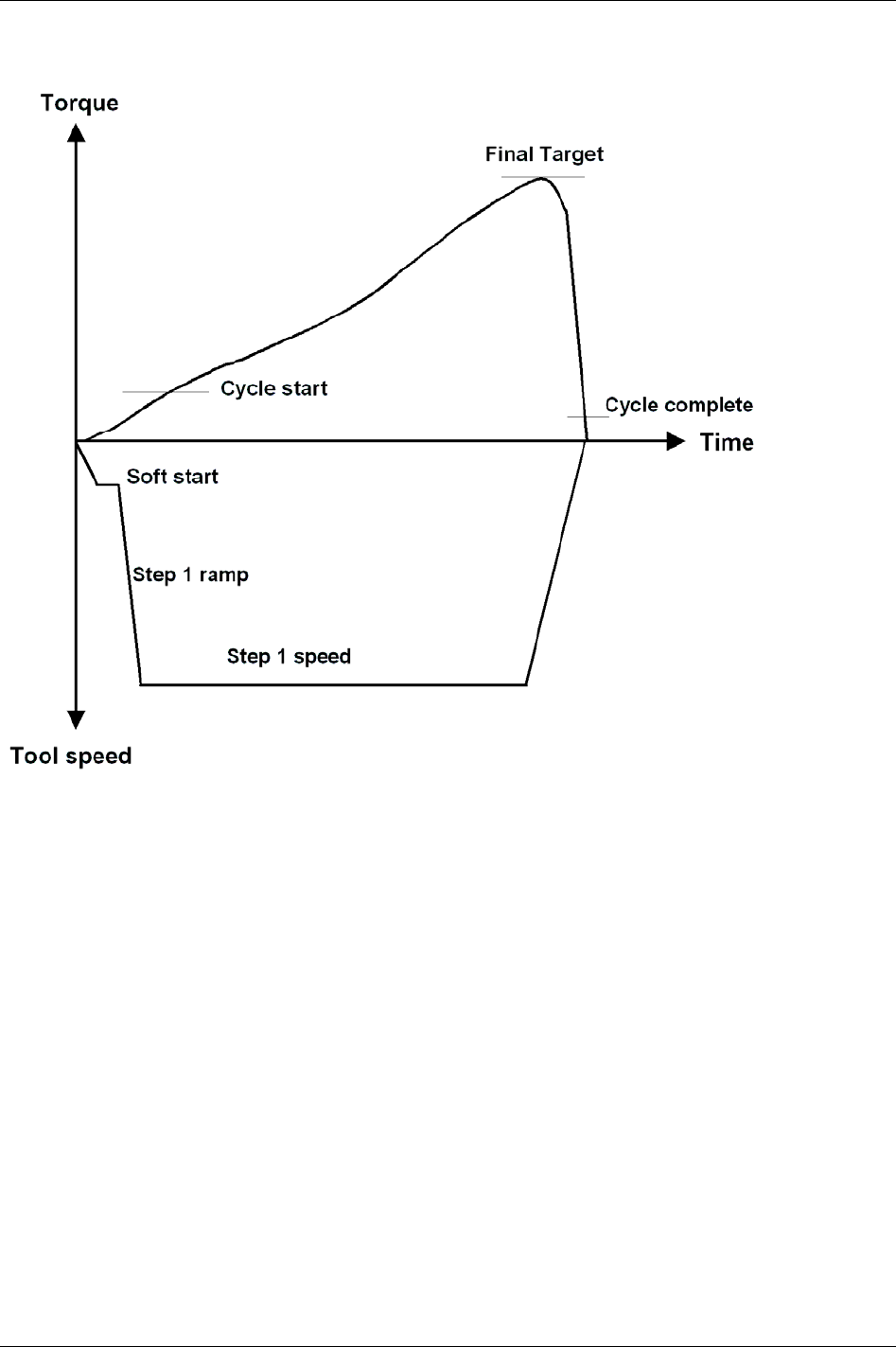
Pset
One stage
Tightening is performed in
One stage until the Final target [P113] torque has been reached. The tool
accelerates quickly to final speed.
48 (330) 9836 3123 01
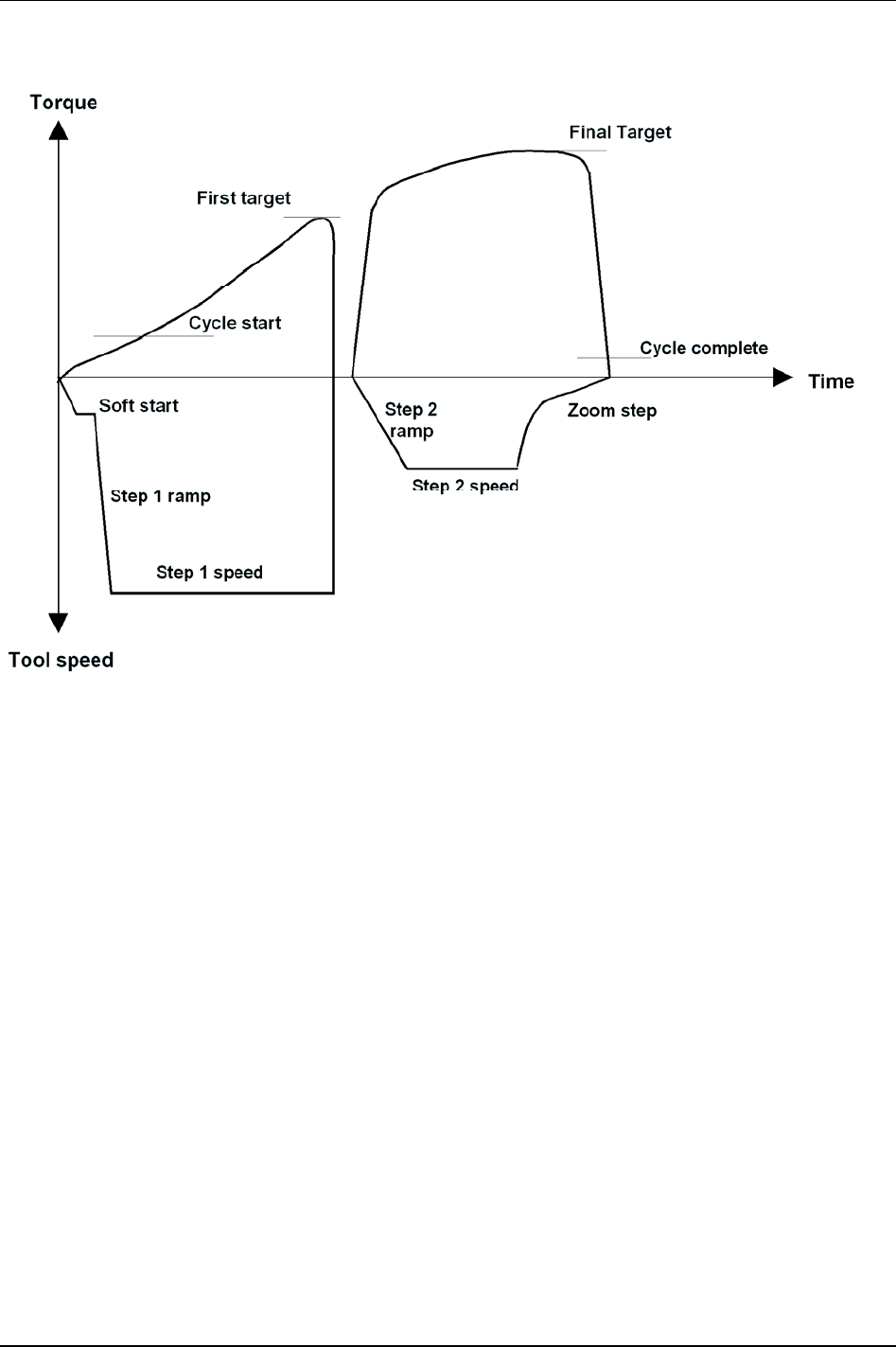
Pset
Two stage
In a
Two stage tightening, the tool operates at high speed during the first stage and a lower speed during
the second stage. The tool stops for about 50 milliseconds between the stages to reduce joint relaxation
and then accelerates for the second stage.
In this example the strategy ends with a Zoom step [P105], which reduces the risk of overshooting.
9836 3123 01 49 (330)
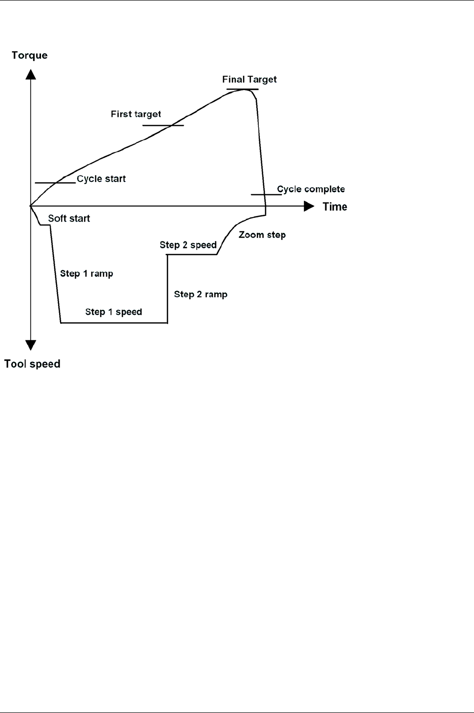
Pset
Quick step
Quick step is a type of two stages tightening with high tool speed during the first stage and a lower tool
speed during the second stage. The speed changes from first to second stage speed without pausing in
between.
In this example the strategy ends with a
Zoom step [P105], which reduces the risk of overshooting.
50 (330) 9836 3123 01
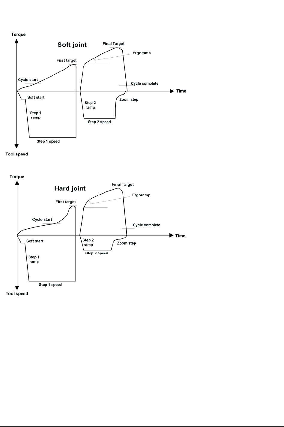
Pset
Ergo ramp
Ergo ramp is a two stage tightening with a constant increase of torque during the second stage. It is set
automatically using the programmed ergo ramp value and the hardness of the joint. This strategy has the
ergonomic advantage of giving the user the same feeling for both soft and hard joints when using the same
Pset. In this example the strategy ends with a
Zoom step [P105], which reduces the risk of overshooting.
9836 3123 01 51 (330)

Pset
52 (330) 9836 3123 01
5.2.3 Control options
Rundown angle
The Rundown angle option monitors the angle at Rundown complete [P116].
If the
Rundown angle [P104] option From start is selected the rundown phase will start when the tool trigger
is pressed. If
Rundown angle [P104] option From cycle start is selected the rundown phase will start when
the torque exceeds
Cycle start [P110]. The acceptance window for the rundown angle is set with the
Rundown angle min [P125] and Rundown angle max [P126].
Zoom step
The Zoom step option reduces tool speed when the torque approaches Final target [P113]. Tool speed is
reduced gradually towards the
Zoom step speed [P138], which can be set between 2 and 20 percent of the
maximum speed. Zoom step produces very accurate results, low scatter and quick tightenings.
Combined Zoom step and Ergo ramp
By combining zoom step and ergo ramp, the advantages of both strategies will be achieved. Tightenings
are precise and, at the same time, ergonomically correct for the operator.
Zoom step and ergo ramp strategies can be combined for most types of bolted joints.
5.2.4 Rehit detection
The re-hit functionality is designed to detect re-tightenings of an already tightened joint, thereby avoiding
batch counting errors etc. Two parameters have been found to be good indicators of a so-called re-hit, tool
speed and tightening angle. If, for two stage torque control tightenings, the tool does not get up to speed
before the first target occurs and the angle of the second stage is not great enough the re-hit alarm is
activated.
For two stage torque control tightenings, the speed must reach higher then ¼ out of
Step 1 speed [P131]
between
Cycle start [P110] and First target [P111] or the angle between First target [P111] and Final target [P113]
must be greater then 120 degrees to avoid a re-hit alarm. For one stage tightenings, the speed at Cycle start
[P110]
and the angle between Cycle start [P110] and Final target [P113] are used as indicators.
The large angle interval required means that for most normal tightenings it is the speed condition that is
met. Only for very soft joints with a low
First target [P111] or one stage tightenings is the angle condition
met.
For two stage angle control tightenings, the re-hit alarm is activated if the tightening is aborted on
Final tq
max [P114]
and the tool speed has not reached ¼ of the Step 1 speed [P131] between Cycle start [P110] and First
target [P111]
. For one stage tightenings, the speed at Cycle start [P110] is used as indicator.
The re-hit functionality is not valid for the Rotate spindle forward/reverse and Reverse angle strategies.
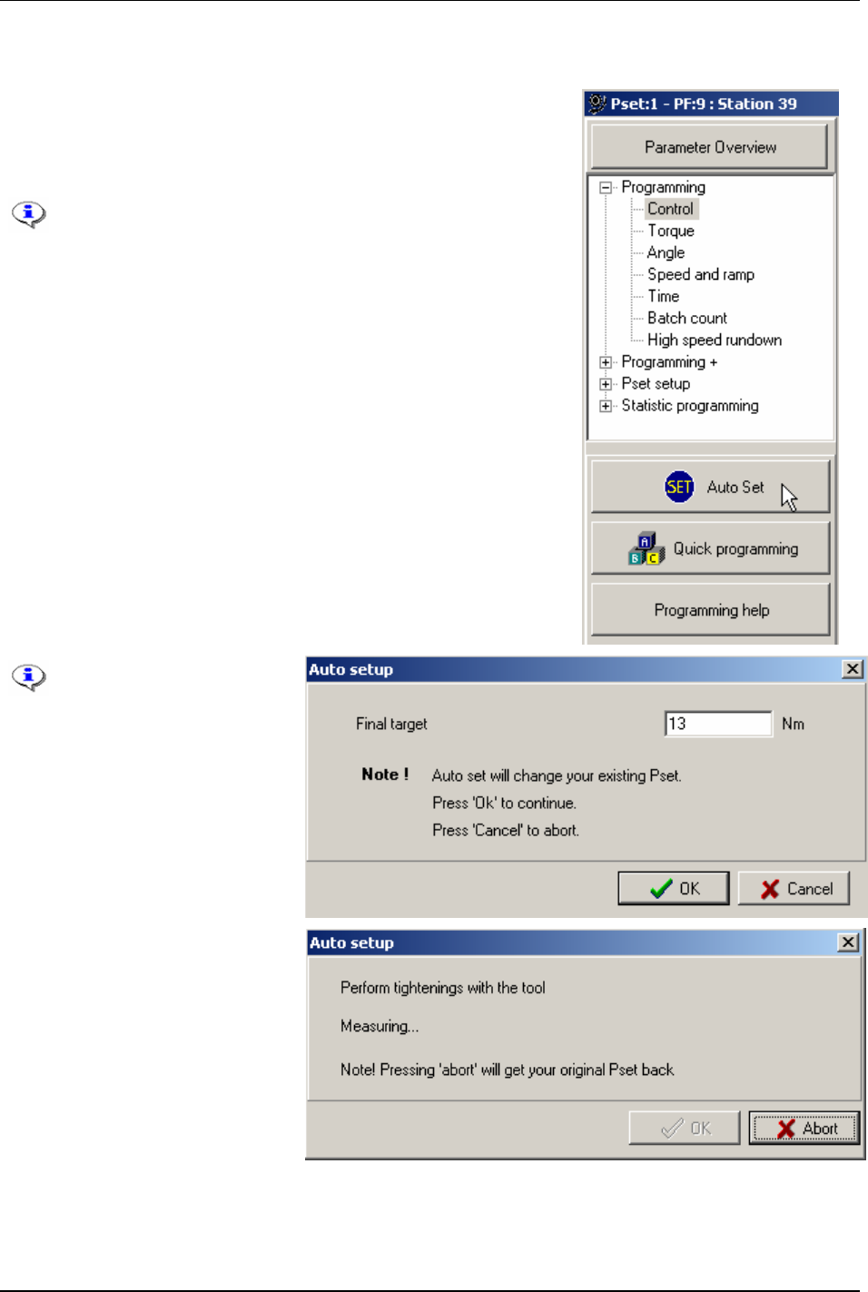
Pset
5.2.5 Autoset
An easy way to program a Pset is to use the Autoset function. Power
Focus adapts the programming to the specific joint characteristics and
sets all the parameters automatically. Autoset does not change any
parameters outside the used Pset.
Autoset can only be selected when a tool is connected and
the PF is switched on.
Control strategy [P100] “Tq con/ang mon” should be set to
Autoset when Tensor S and ST tools are used. With DS
tools strategy “DS con” should be used.
If using an existing Pset, the parameters of which will be
erased and replaced by the Autoset calculated parameters.
Click
Autoset in the Pset window.
A green light on the front panel of the PF indicates that Autoset is
activated. When this signal is shut off, Autoset is finished and the PF
is now programmed for that joint. The Autoset procedure can be
aborted by clicking cancel before the green light shuts off.
By performing Autoset,
the existing Pset
configuration will be
change.
Enter the
Final target [P113] value
and click
OK.
Perform a number of tightenings
with the tool.
The first two tightenings will be
completed at very low speed.
Normally, three to ten tightenings
are required in order for the Power
Focus to calculate and set the
required parameters for the specific
joint characteristics.
Click OK when prompted.
By clicking
Abort before the Autoset procedure is completed will cancel the operation and restore the
previous settings.
9836 3123 01 53 (330)
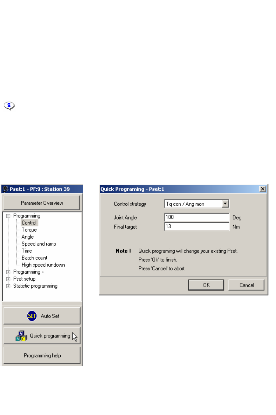
Pset
5.2.6 Quick programming
Quick programming intended to help users to quickly configure a Pset and gives the opportunity to use
the Power Focus after a fast and simple programming.
The joint angle is the distance from when the screw (nut) head touches the surface and the torque starts
to build up, until it reaches the set limit. It is possible to measure the joint angle by using a torque
wrench.
For “hard” joints, it is best to set the value at 30 degrees. For “soft” joints we recommend setting the
joint angle above 100 degrees. This gives a better tightening during the first stage and a distinct second
stage. Adjust the angle if the second stage is too long. It is important that there is a second stage;
otherwise the tool may jerk at full torque (overshoot).
If using an existing Pset, the parameters of which will be erased and replaced by the Quick
programming calculated parameters.
For quick programming, the final target value must be larger or equal to 25 percent of
Tool max torque [T102].
Open an existing Pset or create a new one.
Click
Quick programming in the Pset window.
Select
Control strategy [P100] and enter the joint angle and Final target [P113].
Click
OK to finish.
54 (330) 9836 3123 01
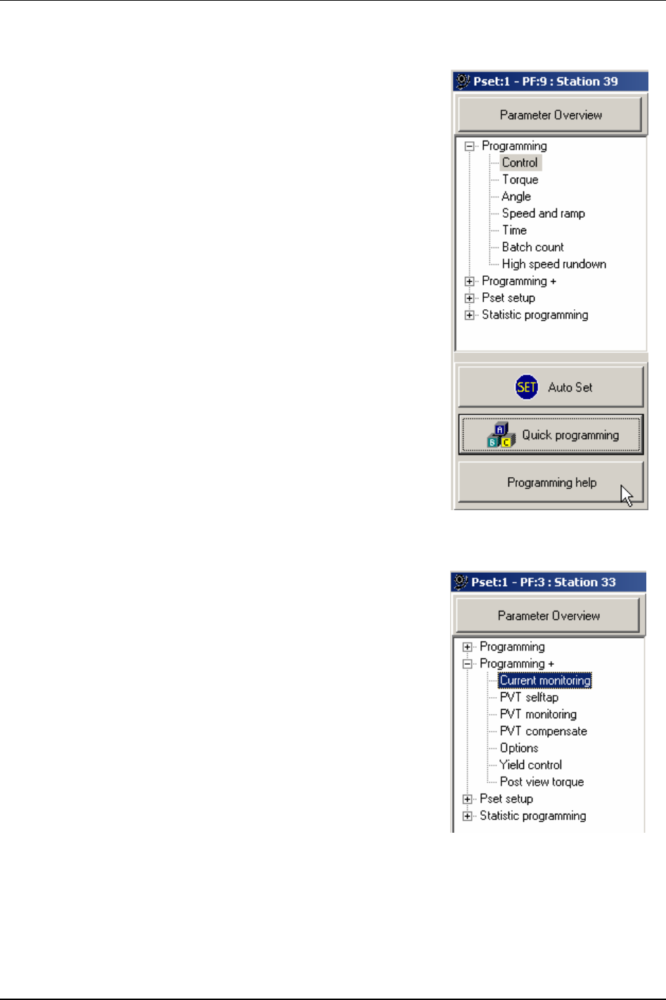
Pset
5.2.7 Programming help
Via the Programming help function ToolsTalk PF can calculate the
selected control and tightening strategy.
Click
Programming help in the Pset window.
5.3 Programming +
This section is for applications where special Pset functionality is
needed.
Expand the
Programming + branch.
Select
Current monitoring and make suitable parameter settings.
The spindle torque is proportional to the motor current. By measuring
motor current a method of measurement that is independent of the
torque transducer is achieved. The torque forming current is expressed
as percentage of the nominal current at
Tool max torque [T102]. With
Current monitoring [P200] selected it is possible to set an acceptance
window for the torque as a redundant process control.
9836 3123 01 55 (330)

Pset
In the Pset
Programming + branch,
select
PVT selftap.
Make suitable parameter settings.
When the joint has a torque peak at
the start of the tightening it is
recommended to use the PVT
selftap monitoring option,
Selftap
[P210], to ensure that the tightening
achieves the right characteristics.
PVT selftap also makes it possible to perform tightenings where the start torque is higher than the
Final
target [P113] or Final tq max [P114].
The selftap interval starts at
Cycle start [P110]. During the Selftap interval [P211] the torque has to reach at
least the
Selftap min [P213] level but must stay below the Selftap max [P214] limit. The Selftap max [P214] is
monitored in real time during the self tap interval. The
Selftap min [213] value is evaluated against the
selftap interval peak value at the end of the interval.
To reduce the effects of noise, the PVT selftap monitors mean values calculated from a number of
windows. A fewer number of windows means that more samples will be grouped together, hence one
odd sample will have less impact on the calculated mean value and vice versa. A higher
Number of self tap
windows [P212] will make the monitoring more sensitive whereas a lower number will filter more noise.
56 (330) 9836 3123 01
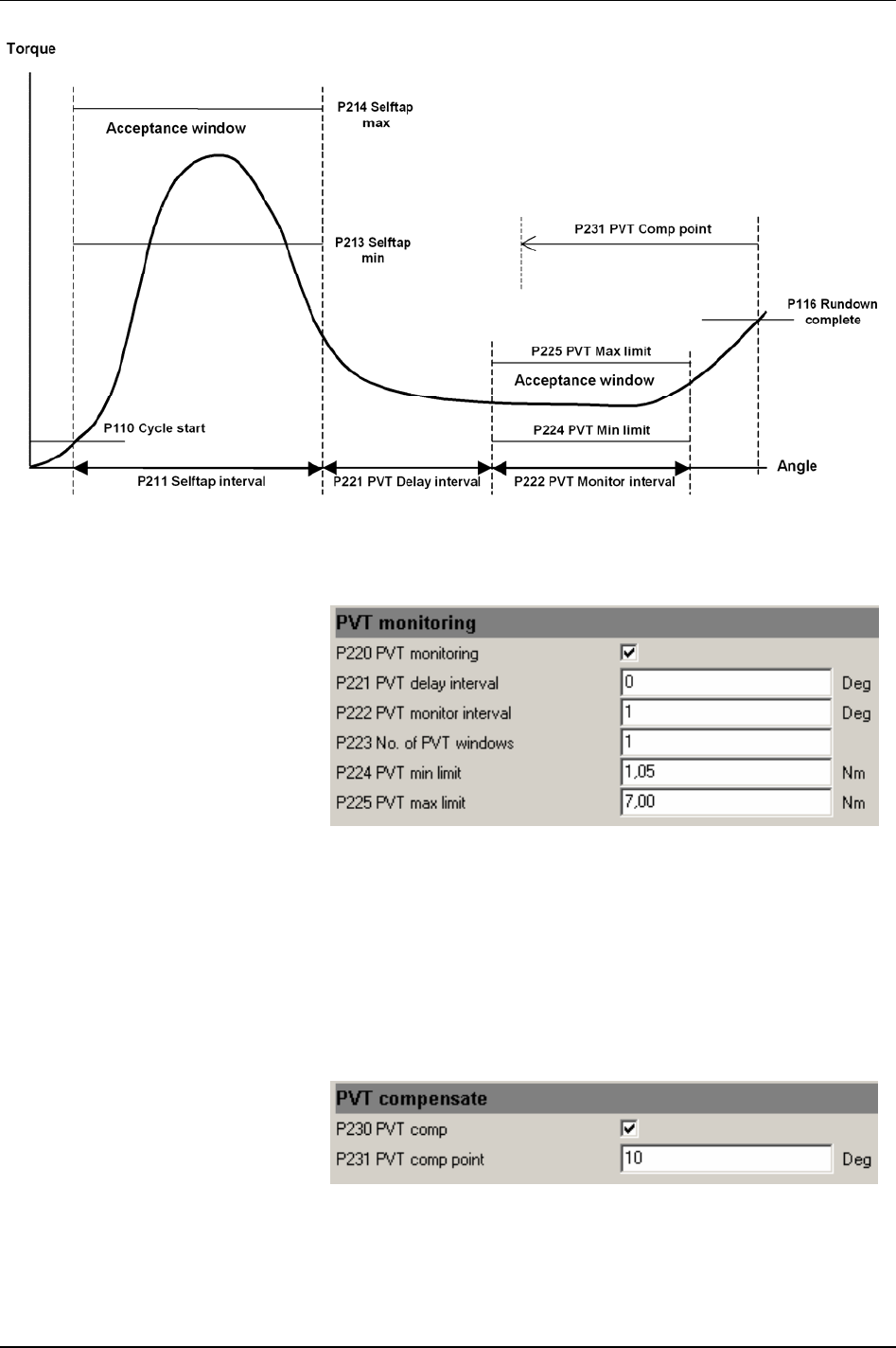
Pset
Graph illustrating PVT selftap, PVT monitoring and PVT compensate
In the Pset Programming + branch,
select
PVT monitoring.
Make suitable parameter settings.
When the joint torque has to pass
through an acceptance window prior
to
Rundown complete [P116] to pass as
a correct tightening it is
recommended that the PVT
monitoring option is used.
See the graph in the section for PTV selftap.
With
PVT monitoring [P220] selected it is possible to set an acceptance window for the torque before
Rundown complete [P116]. The PVT max limit [P225] is monitored in real time during the monitor interval
and if exceeded, the tool will stop immediately. The
PVT min limit [P224] value is evaluated against the
monitor interval peak value at the end of the interval.
To reduce the effect of noise, the PVT selftap monitors mean values are calculated from a number of
windows. A higher
Number of self tap windows [P212] will make the monitoring more sensitive whereas a
lower number will filter more noise.
In the Pset
Programming + branch,
select
PVT compensate.
Make suitable parameter settings.
9836 3123 01 57 (330)
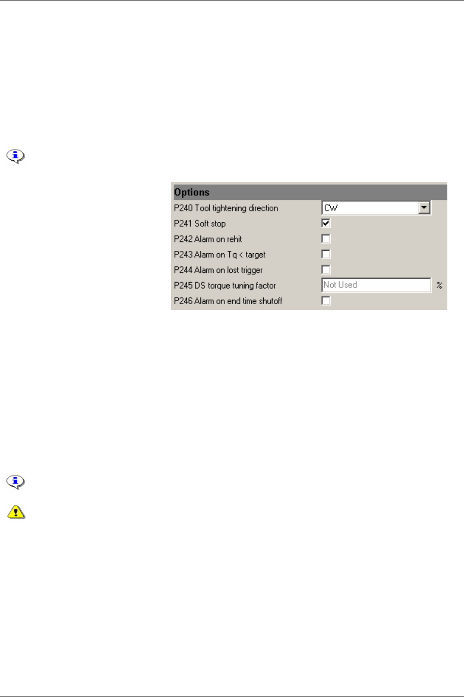
Pset
See the graph in the section for PTV selftap.
Via this function the PF allows the torque levels to be independent of the prevailing torque, (known as
PVT compensate) during the rundown phase. This makes the torque levels change dynamically for each
new tightening. In this way, the PVT compensate value is used as a base reference for the torque used
during tightening.
The different torque values, e.g.
First target [P111] and Final target [P113], are compensated for the
prevailing torque during the rundown phase. The PVT compensation value is calculated at
Rundown
complete [P116]
as an average torque from an interval preceding the PVT comp point [P231]. The tightening
result is presented with the compensation torque subtracted.
Final tq max [P114] is also compensated with the PVT compensate value.
In the Pset
Programming + branch,
select
Options.
Make suitable parameter settings.
There are different variables that
control the tool rotation direction:
tool direction ring,
Tool tightening
direction [P240]
and Tightening strategy
[P101]
.
Tightening a screw or nut is in accordance with the selected
Control strategy [P100]. Loosening is equal to
reversing the screw or nut. Loosening speed and ramp can be programmed. Reverse is a control strategy
that loosens the screw or nut a programmed number of degrees. The direction is always the opposite of
the tightening direction.
The position of the tool direction ring at the time the tool trigger is pressed will decide the direction of
rotation. If the ring is in the right position the tool will rotate clockwise (CW), and counter clockwise
(CCW) if the ring is in the left position. However, the direction will not change if the direction ring is
moved while the tool is running.
With the parameter
Tool tightening direction [P240] the default tightening direction of the tool is selected.
This means that the tool will tighten the joint clockwise (right-hand threaded joints) if “CW” is selected
and the direction ring is in the right position. Select “CCW” for counter clockwise tightenings.
The direction ring adjusts the rotation direction of the tool socket, while parameter
Tool
tightening direction [P240]
decides whether it is a right- or left handed threaded joint.
If different tightening directions are used on the same tool, there is a risk that the operator
will use the wrong direction for a specific screw. This could lead to unexpected reaction
forces in the tool that could be dangerous for the operator.
58 (330) 9836 3123 01
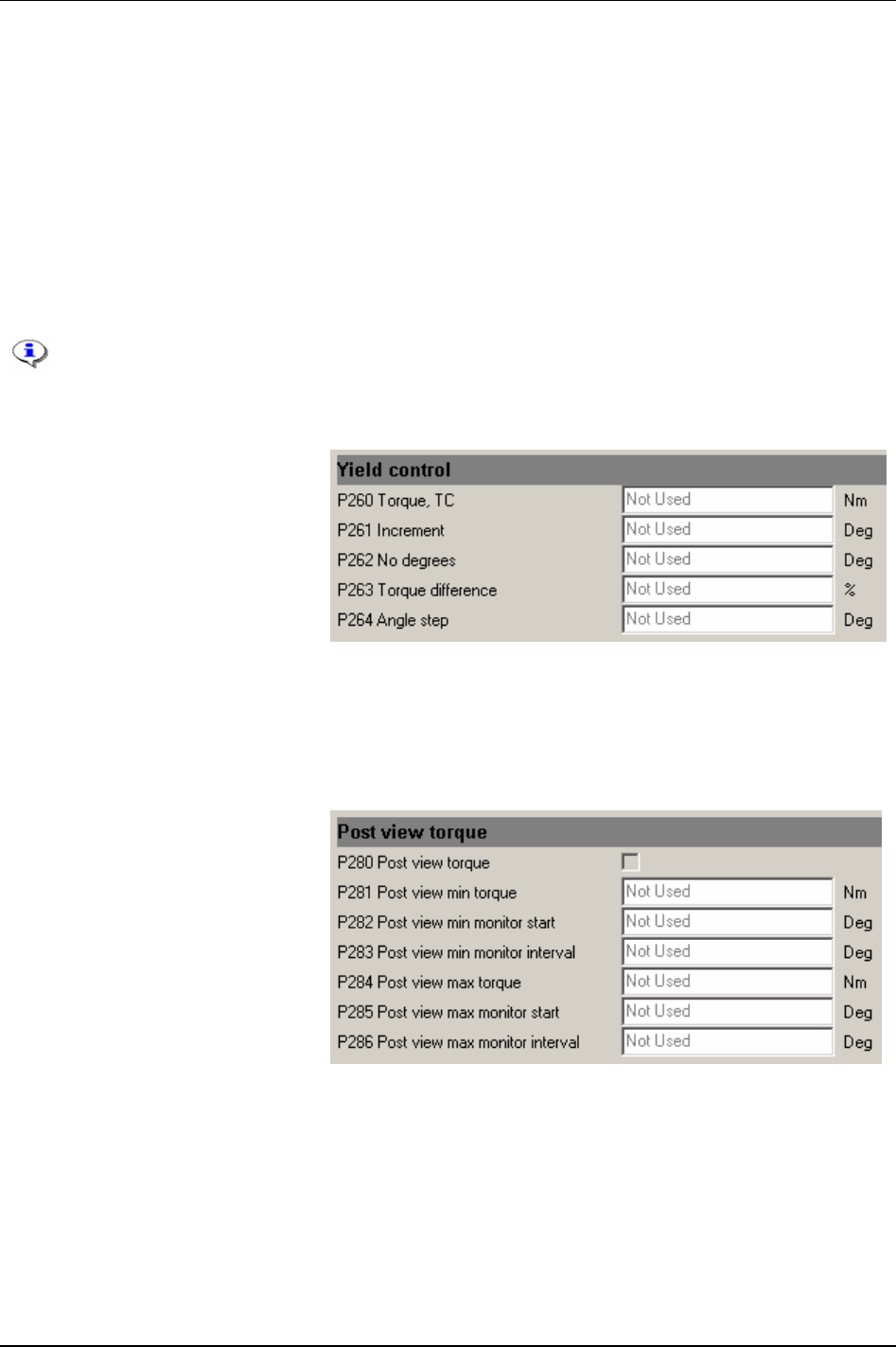
Pset
With regard to reverse ang or rotate spindle reverse, the “active” direction is the opposite from the Tool
tightening direction [P240]. For instance, if “CW” is to be selected turn the direction ring to the left
position. For safety reasons, it is not possible to loosen the joint with these strategies.
The remote start input is connected in parallel with the tool trigger and has the same functionality. If
remote start input is used the tool trigger is disabled.
If a digital input is used as start signal input, the direction ring and trigger on the tool are bypassed. If
tool start from digital input is selected and activated, the tool will start tightening in the direction
programmed in the parameter
Tightening direction [P240].
The Field bus tool start input works in the same way as the tool start from digital input. The 4-pin
connector must be wired correctly.
The 4-pin connector on Power Focus back panel must be wired correctly.
Do not use tool start from digital input via an I/O Expander on a synchronised tool group.
Use only the four internal digital inputs.
In the Pset
Programming + branch,
select
Yield control.
Make suitable parameter settings.
Yield control is activated by selecting
the
Control strategy [P100] to Yield. The
Tightening strategy [P101] can be set to
One stage, Two stage or Quickstep.
Yield control will always interact in
the last stage of the tightening.
Zoom step [P105] strategy ending is eliminated when yield control is selected. An additional tightening
angle can be added after the yield point is reached by setting an angle to the
Angle step [P264] parameter.
See function description for Yield control in section
Control strategies.
In the Pset
Programming + branch,
select
Post view torque.
Make suitable parameter settings.
Some joints have a torque peak prior
of
Rundown complete [P116]. Post view
torque function makes it possible to
monitor torque values during two
specified angular intervals. The
interval start is defined as angle prior
to
Rundown complete. Torque is then
monitored for a specified angular
interval. Evaluation (OK/NOK) is
done when rundown complete is
reached.
Click Store to save the settings.
9836 3123 01 59 (330)
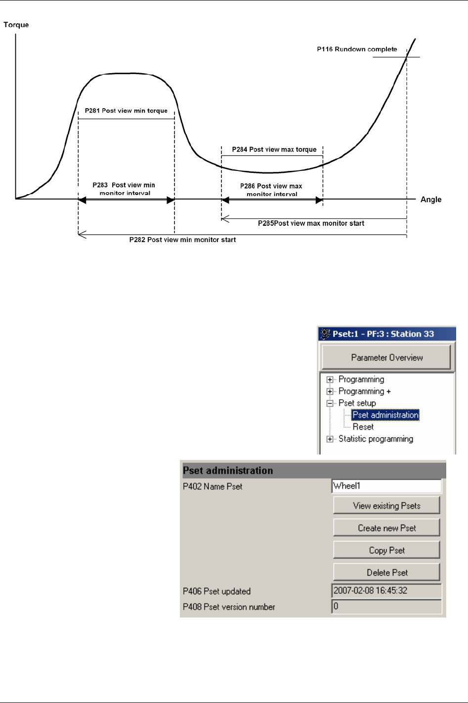
Pset
Graph illustrating Post view torque
5.4 Pset setup
Expand the Pset setup branch.
Select
Pset administration.
Add a name for the Pset (optional).
This section also contains options for
View existing Pset, Create new Pset,
Copy Pset and Delete Pset.
60 (330) 9836 3123 01
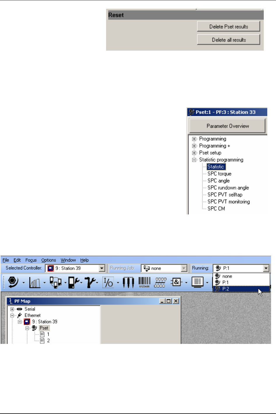
Pset
In the Pset setup branch, select Reset.
Click
Delete Pset result to select the
Pset result to remove from the Power
Focus memory.
When clicking
Delete all results a
confirmation pop windows appears.
Select “Yes” to accept or “No” to abort
operation.
Click
Store to save the settings.
5.5 Statistic programming
Expand the Statistic programming branch.
In this branch it is possible to define conditions to be included in the
statistical calculations for the tightenings (Psets).
Click
Store to save the settings.
5.6 Running a Pset
To run (activate) the Pset, select the Pset in the Selection panel or via any configured Pset control source.
9836 3123 01 61 (330)
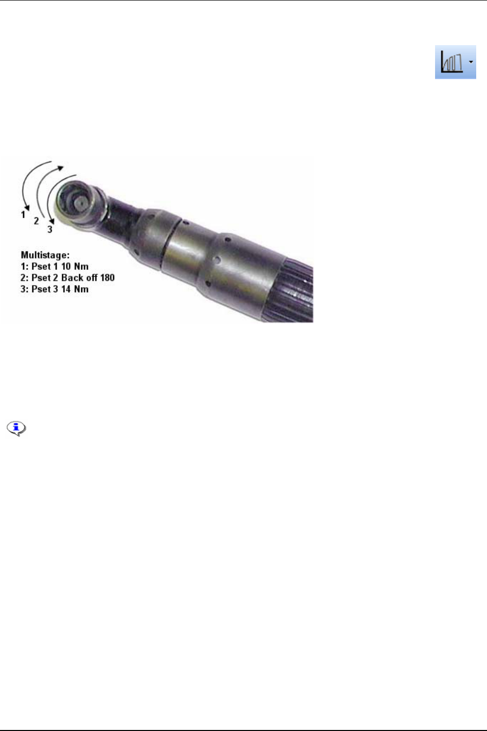
Multistage
6 Multistage
The Multistage feature offers a dynamic link to eight parameters in several steps for
performing a sequence of operations.
A typical application scenario such as joint conditioning, where the fastener is run to a torque level of 10
Nm then backed off by 180 degrees and then fastened to a final torque level of 14 Nm. This operation
would be regarded as a three step Multistage. This is performed by the operator when in a hand held
configuration by depressing the trigger in the normal way until the end of the operation, or alternatively
when used in a fixed operation where the start signal is either latched or externally triggered.
The Multistage tightening results and statistics are a combination of all the results from the different Psets
within the Multistage. The default setting is all results from the last Pset in the Multistage.
Individual Pset min and max limits function in all stages and the tool will shut off when a max limit is
exceeded (or for any reason if the min limit is not reached) as per normal operation. The result displayed
will then be taken from the stage where the shut off occurred.
This section includes screenshots from ToolsTalk PF. The screenshots shows examples of
parameter settings and is NOT intended to be generally applicable. Check with your
local Atlas Copco reprehensive how to set up your specific system environment.
See chapter
Parameter list for a description of all available Multistage options.
9836 3123 01 63 (330)
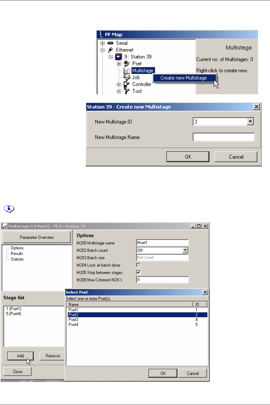
Multistage
6.1 Create new Multistage/Open Multistage
In the PF Map, mark Multistage,
right-click and select Create New
Multistage
. Alternatively, double-
click on an existing Multistage to
open the configuration window.
Select
New Multistage ID, enter
the
New Multistage name
(optional) and click
OK to open
the Multistage window.
Click
Add to select Psets to be included in the Multistage.
In the left upper window part, make selections for
Options, Results and Statistics (mark to activate).
Click
Store to save the settings for the Multistage.
The selection of a Multistage (via PC, Selector, Digital input etc) is handled in the same
way as a Pset.
64 (330) 9836 3123 01
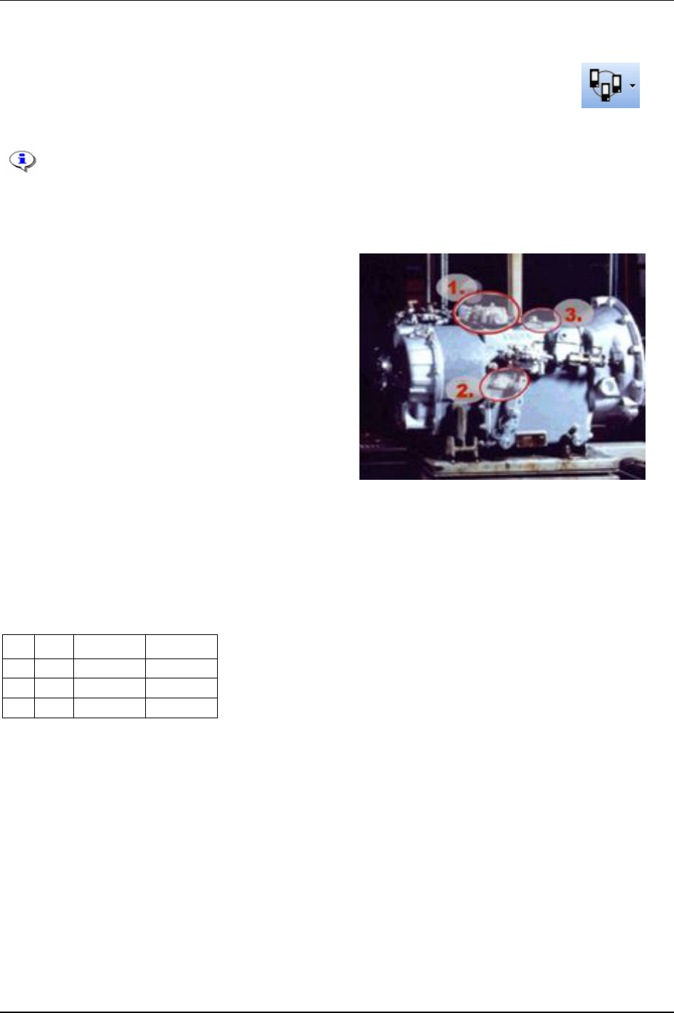
Job
7 Job
The Job function is advantageous when an object has bolts/screws that require different
torque and angle values for tightening. A Job is useful when an object needs different
Psets and Multistages. Instead of manually selecting each Pset/Multistage, the Job
functionality keeps Psets and Multistages in a predefined order.
This section includes screenshots from ToolsTalk PF. The screenshots shows examples
of parameter settings and is NOT intended to be generally applicable. Check with your
local Atlas Copco reprehensive how to set up your specific system environment.
See chapter
Parameter list for a description of all available Job options.
Power Focus allows 30 Psets/Multistages in a Job, and
the storage of 99 Jobs (with the memory setup (see
chapter
Controller) it is possible to store up to 400 Jobs).
The Psets/Multistage included in a Job can be selected
from a stand alone PF (RBU silver) or from several PF
units in a Cell (RBU gold). The figure to the right
shows an example of an object with bolts that require
different torque values:
Four bolts that require a torque of: 39 Nm
Three bolts that require a torque of: 70 Nm
One bolt that requires a torque of: 88 Nm
For this example three different Psets have to be
created:
Pset1: final target 39 Nm
Pset2: final target 70 Nm
Pset3: final target 88 Nm
By combining the Psets in the above example the following Job list is created (se table below).
PF Pset Pset name Batch size
1 1 Pset1 4
1 2 Pset2 3
1 3 Pset3 1
The Job in this example is performed by one single PF. “Batch size” means the number of times the
tightening should be repeated. A “JOB OK” signal is received from the Power Focus when all
tightenings have been performed correctly.
9836 3123 01 65 (330)

Job
The Job function in Power Focus can be defined by two categories. Standalone Job is when just one
PF is involved in the Job.
The standalone Job function is available with RBU gold, silver, X and DS.
Cell Job
is a Job in which several PF units are involved.
All PF units that perform a Cell Job must belong to the same
Job group. A Job group consists of a
maximum of 20 controllers within the same Cell (see chapter
Controller for more information).
A single PF can only belong to one Job group, but it is possible to create several Job groups in the
same Cell.
In a Job group, all included controllers are Job members. One of the Job members acts as a Job
reference, the others act as Job clients (see figure on next page). The Job reference retains a list of all
Psets and Multistages available for all Job members. The Job reference is the main controller and
remotes the Job clients.
The Cell Job function is only available with the RBU Gold.
66 (330) 9836 3123 01
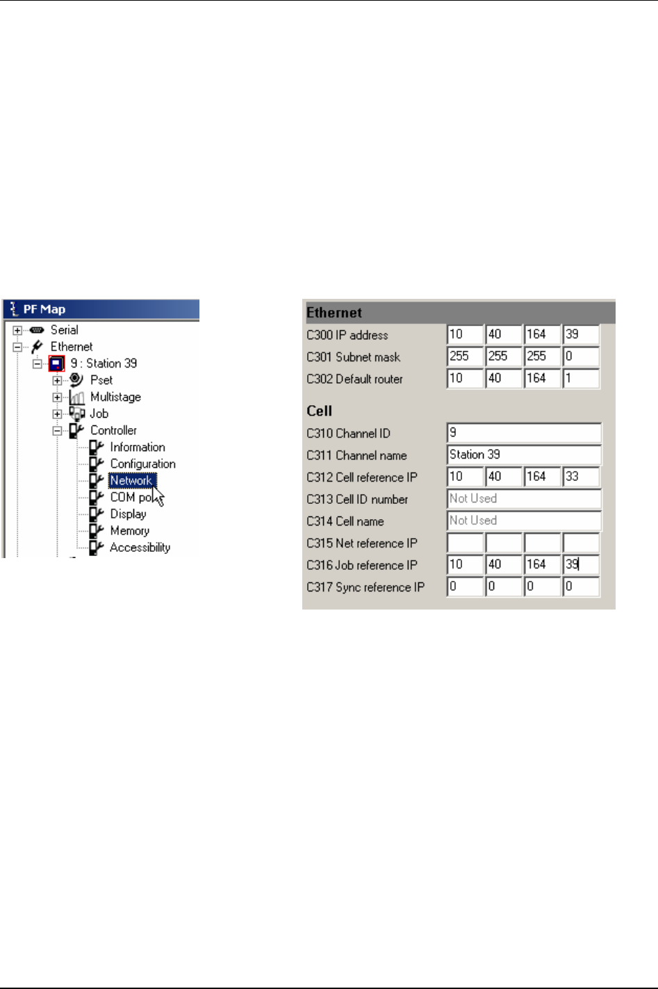
Job
7.1 Create a Job group
The PF units in a Job group must be working in the same Cell. Therefore, when creating Job groups a
Cell has to be configured (see chapter
Controller for more information).
Once the Cell is configured the next step is to create a Job group including Job reference and Job client.
In the PF Map, select
Controller -> Network.
To define a
Job reference, set the parameter Job reference IP [C316] address equal to the parameter IP
address [C300] of the same controller.
To define a
Job client, set the Job reference IP [C316] to the IP address [C300] of the Job reference.
Press
Store to save the settings.
Reboot the PF.
9836 3123 01 67 (330)
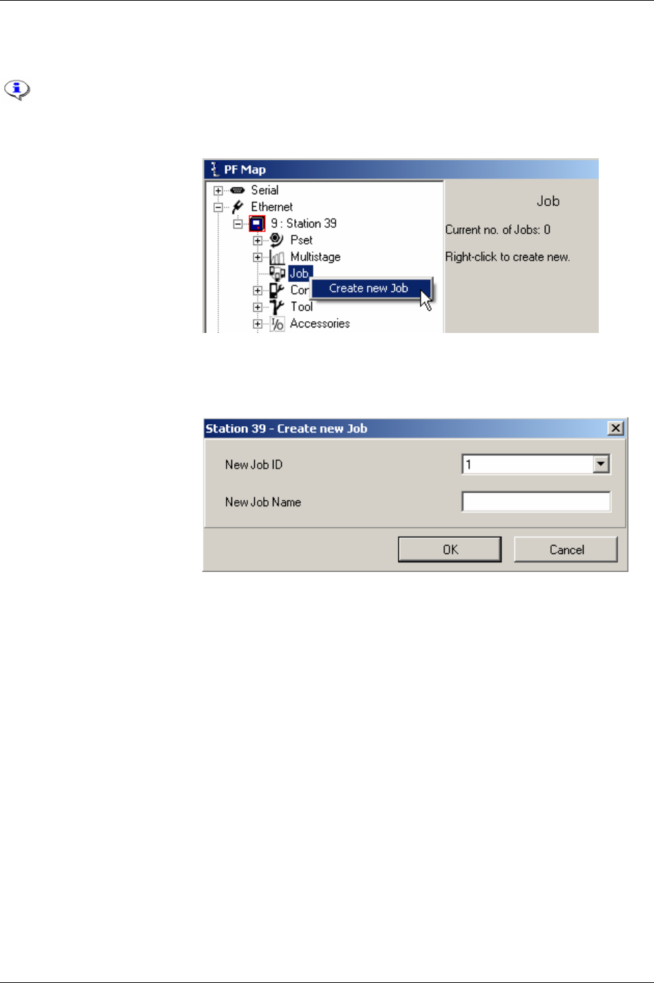
Job
7.2 Create new Job
With the configuration setup it is possible to store up 400 Jobs (see chapter
Controller for
more information).
When creating a Cell Job the programming has to be done in the Job reference controller.
Right-click
Job in the PF Map
and select
Create new Job.
Alternatively,
double-click on
an existing Job to open the Job
configuration window.
(Every Job has a unique ID
number between 1 and 99.)
Select
New Job ID in the drop
list, give the Job a name
(optional) and click
OK to open
the Job window.
68 (330) 9836 3123 01
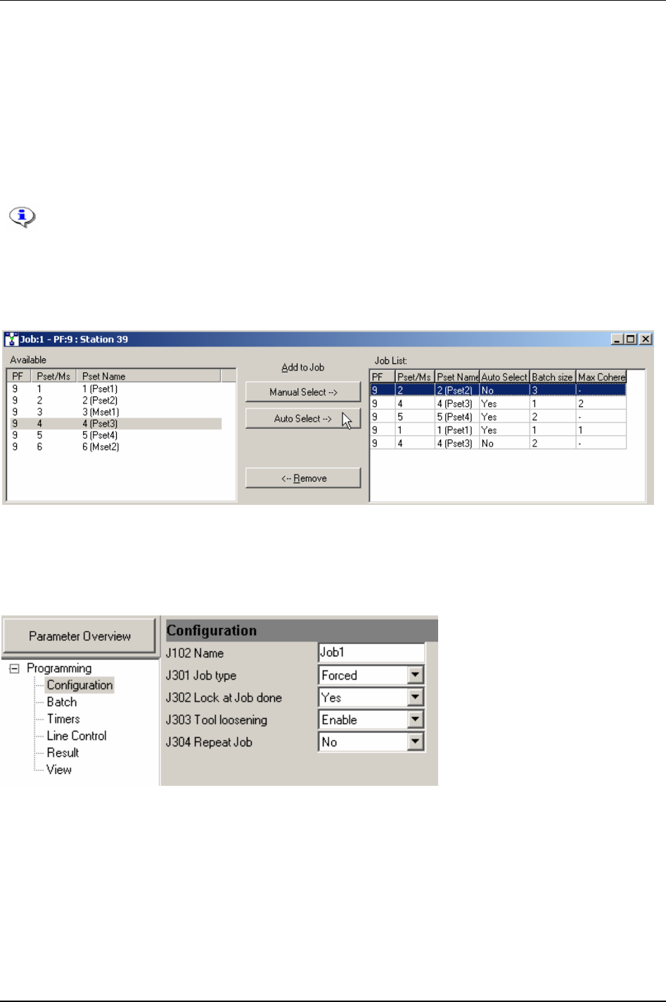
Job
The upper part of the Job window shows the available Psets and Multistages and Job list, see Job list
[J300] in chapter Parameter list for a description.
Select Psets/Multistages and add them to the Job list by clicking on either
Manual select or Auto select. It
is possible to change between manual and auto select afterwards by clicking in the table in the auto select
column.
To change
Batch size for a Pset/ Multistage, click in the column in the Job list table and enter a value.
To specify
Max coherent NOK’s, click in the column in the Job list table and enter a value.
Auto select is not allowed for free order Jobs, with two or more Psets/Multistages selected
from the same Power Focus.
The batch size defined in Job overrides the batch size defined for a specific Pset/Multistage
(see parameters
Batch count [P150] and Batch count [M202]). It is not recommended to use the
batch count function in Job and Pset/Multistage settings simultaneously.
The lower part of the window presents the programming section. Select Configuration and set Job order
type [J301], Lock at Job done [J302], Tool loosening [J303] and Repeat Job [J304].
Continue and make settings for the options in
Batch, Timers, Line control, Result and View.
In the PF Map, select
Controller ->Configuration.
Make a selection for
Job select source [C201].
Press
Store to save the setting.
9836 3123 01 69 (330)

Job
7.3 Select Job
In a Job selection the Job ID is used. After a Job has been selected it is not possible to select a new
Job until the first tightening is started or a batch increment is performed. At that point the only way to
select a new Job is either to complete the running Job or to abort the running Job.
Sources that Jobs can be selected and aborted from are “DigIn” (digital input), “Ethernet/serial”,
“identifier”, “Field bus” and the “PF keyboard”.
Power Focus allows two different possibilities for Job selection;
Job select source [C201] and Job select
source override [C202]. To be able to select a Job at least one of the two parameters has to be set.
Job select source override [C202] has a higher priority than Job select source [C201]. If a Job is selected
from
Job select source override [C202], it will always terminate a present Job and be selected instead.
If a Job is chosen from
Job select source [C201] then it is possible to select a new Job from the same
source or from
Job select source override [C202]. But if a Job is chosen from Job select source override
[C202]
then it is only possible to select a new Job from the same source.
The system will remember the most recently selected source until the Job is either
completed or aborted.
If a new Job is selected via
Job select source override [C202], then a running Job will be
aborted and the new one will be started instead. To be able to select/abort a Job from the
PF Graph display,
Job select source [C201] or Job select source override [C202] must be set
to “PF keyboard”.
A Cell Job can only be selected or aborted from the Job reference.
If selecting an empty Job, without any Pset/Multistage included, Power Focus will send a
Job OK signal.
To be able to select a Cell Job the Job reference needs to communicate with the Job
clients that form the selected Job. Otherwise the Job reference will not start the Job. All
the Job clients detect communication failure with the Job reference and vice verse. If the
Job reference loses communication with a Job client it will try to re-establish the
communication.
Two cases when the Job reference loses the communication with a Job client during a running Job:
If the disconnected Job client has tightenings left to perform, the Job reference will abort the
running Job immediately.
If the disconnected Job client did not have any tightenings left to perform, or had no part in the
running Job, the Job will continue.
If a Job client loses communication with its Job reference, the Job client immediately stops running
the Job and locks the tool.
70 (330) 9836 3123 01
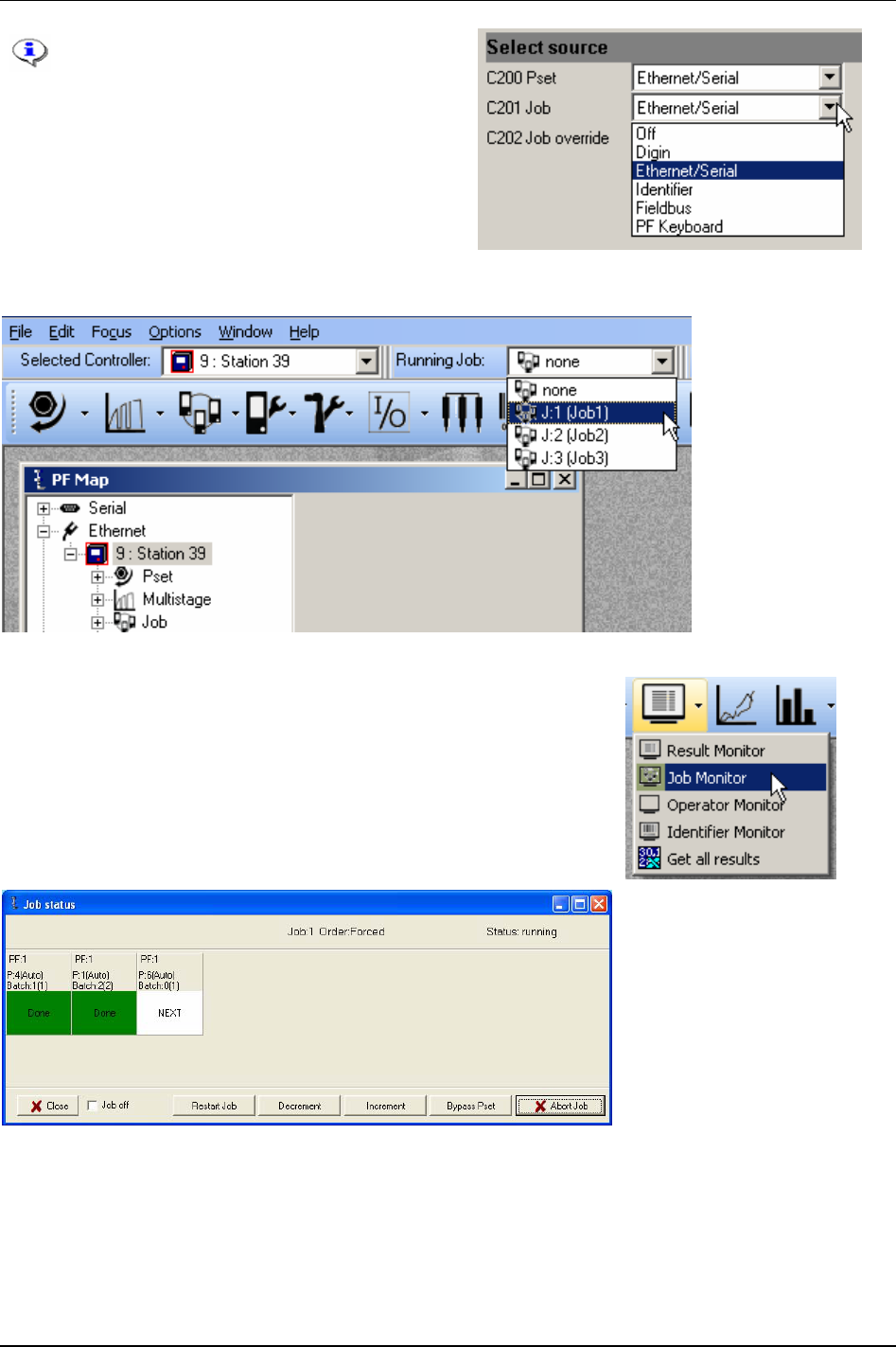
Job
To run the Job from ToolsTalk PF, set
parameter
Job select source [C201] to
“Ethernet/Serial”.
Select the Job to run in the
Selection panel
In ToolsTalk PF, click on the arrow to the right of the
Monitor icon and
select
Job Monitor.
Job monitor displays the selected Job and provides a management
function.
For description of
Job off, Restart Job, Decrement, Increment, Bypass
and
Abort Job, see section Functions in the Job monitor.
9836 3123 01 71 (330)

Job
7.3.1 Functions in the Job monitor
Function Description
Restart Job This function allows the user to restart the running Job without needing to reselect the Job. All batch
counters in the running Job are reset and the Job timer restarts.
Decrement Batch decrement makes it possible to redo the last tightening/increment in a Job. The batch counter of
the Pset or Multistage is decreased by one step. It is not possible to go back one step after the Job has
been completed.
The Job batch decrement function is accessible only from the Job reference controller.
Increment Batch increment makes it possible to skip the batch counter value of a Pset/Multistage without
performing a tightening. It is possible to complete a Job by using the batch increment function.
After performing batch increment in a Job, the Job status will be NOK (not OK) when
Batch status at
increment/bypass [J311]
is selected. Otherwise, the Job status will be OK.
In a Job with free order, only the Job client with the active Pset/Multistage is able to utilise batch
increment.
In Jobs with forced order, the Job client with the active Pset/Multistage and the Job reference are able to
utilise batch increment.
Bypass Bypass skips a specific Pset/Multistage in a running Job, independently of batch size.
The batch counter will be set equal to the batch size value and the Pset will be considered as completed
when a Pset/Multistage is bypassed. The Job status will be OK/NOK depending on the parameter
Batch
status at Increment/bypass [J311]
.
In a Job with free order, only the Job client with the active Pset/Multistage is able to use the bypass
function.
In a Job with forced order, the Job client with the active Pset/Multistage and the Job reference are able
to use bypass the function.
Abort Job Abort Job is only accessible via the Job reference controller. Abort can be an external signal as well as
an internal order (see
Max time to start Job [J320] and Max time to complete Job [J321]).
When a Job abort request is received the Job functionality will wait for completion of the ongoing
tightening result before aborting the Job.
Job off This function offers the possibility to turn off the Job function and unlock all involved tools.
Running Job: Selecting Job off for a running Job is equal to aborting Job, thus the tool/tools will always
be enabled. The Job reference will order all Job members to select the latest Pset from the digital input,
Field bus or selector (in case one of these is Pset select source [C200]) otherwise the latest selected Pset
in the Power Focus will remain.
No running Job: The Job reference will unlock the tools of all Job members. The Job reference will also
order Job members to select the latest Pset, which was selected from the digital input, Field bus or
selector (in case one of these is the
Pset select source [C200]). Otherwise the latest selected Pset in the
Power Focus will remain.
When a PF is in Job off mode it is possible to perform tightening with any existing Pset or Multistage.
As long as the Job reference is in Job off mode the user cannot select a new Job, the Job off mode must
first be inverted.
The only occasion when the Job off function affects the Job clients is when they have lost
communication with their Job reference. In this case there is the possibility to unlock the Job clients
locally by using the Job off function.
Only the Job reference will remember the Job mode after a
reboot.
Job status
(information)
Job OK: Received if all Psets/Multistages included in the Job have been correctly performed,
alternatively if batch increment/bypass has been used (presupposed that batch increment/bypass is
configured as an OK event).
Job NOK: Received if any Pset/Multistage included in the Job has not been correctly performed.
Alternatively it is considered as NOK (Not OK) if batch increment/bypass has been used (presupposed
that Batch Increment/Bypass is configured as an NOK event).
Job aborted: Received if a Job is considered aborted.
72 (330) 9836 3123 01

Job
7.4 Unlock the tool
Unlock the tool by selecting a new Job, deleting all existing Jobs or select Job off.
It is only possible to unlock the tool from the Job reference.
It is not possible to unlock the tool by rebooting the PF.
9836 3123 01 73 (330)
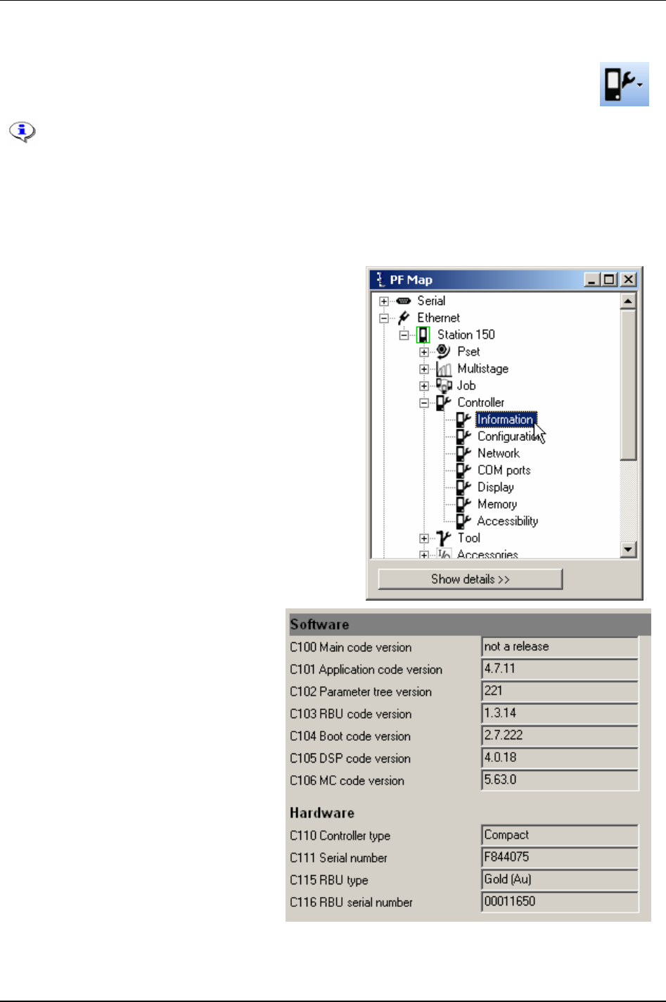
Controller
8 Controller
The Controller contains configurations common to all tightenings and is unique to each PF.
This section includes screenshots from ToolsTalk PF. The screenshots shows examples of
parameter settings and is NOT intended to be generally applicable. Check with your
local Atlas Copco reprehensive how to set up your specific system environment.
See chapter
Parameter list for a description of all available Controller options.
8.1 Information
Expand the Controller branch in the PF Map.
Double-click on
Information.
This window contains information about
the ToolsTalk PF
Software and the Power
Focus
Hardware.
9836 3123 01 75 (330)
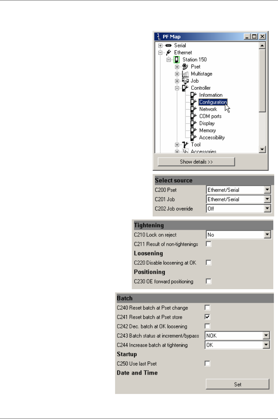
Controller
8.2 Configuration
In the PF Map Controller branch, double-click on
Configuration.
Make settings for
Select source.
Make settings for Tightening, Loosening and
Positioning.
Make settings for Batch and Startup.
Click
Set under Date and Time to store
computer and user time to PF.
Click
Store to save settings.
76 (330) 9836 3123 01
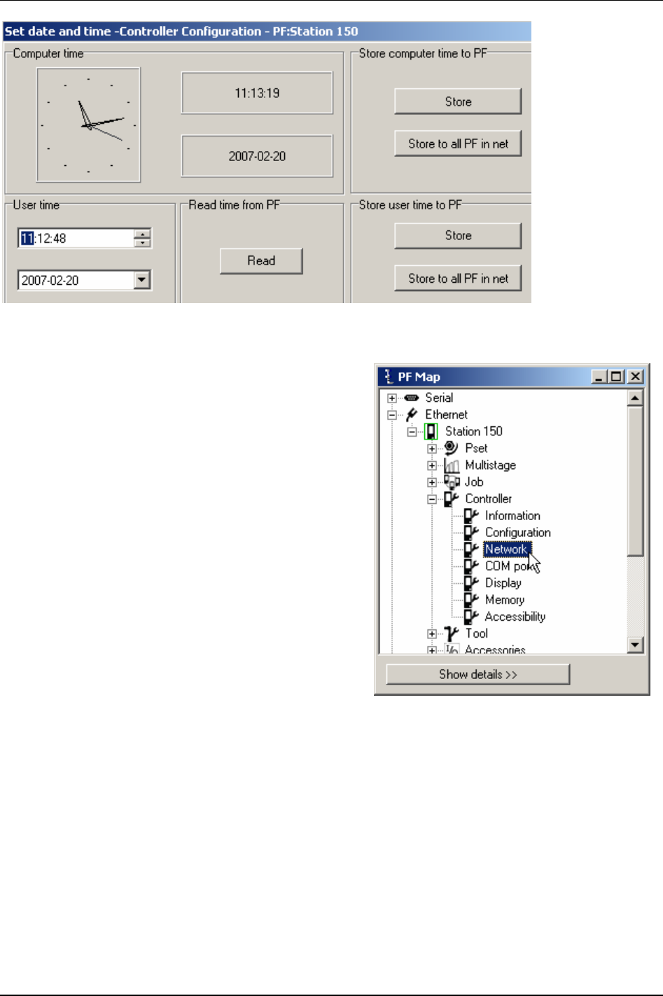
Controller
8.3 Network
In the PF Map Controller branch, double-click on Network.
9836 3123 01 77 (330)
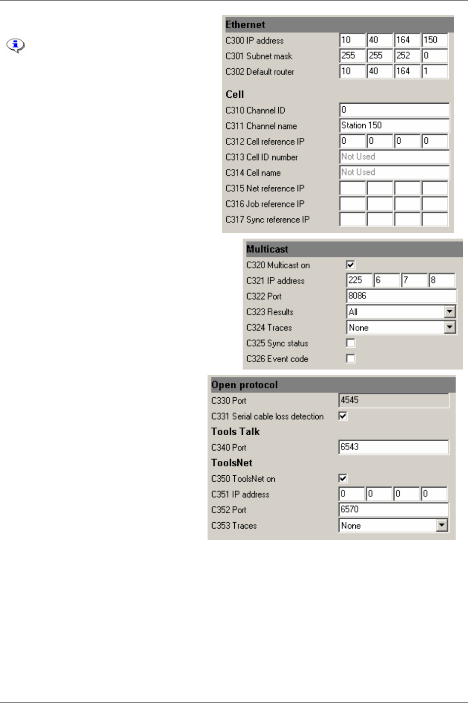
Controller
Make settings for Ethernet and Cell.
Power Focus uses both Ethernet and
serial communication, and works
together with ToolsTalk PF and
database applications such as
ToolsNet, etc.
The Cell and Net concept allows all PF
units on an assembly station to
communicate and work together. For
also section
Job and section Sync.
If used, activate and setup
Multicast.
Make settings for Open protocol and the
Tools Talk port.
I used, activate and setup
ToolsNet.
Click
Store to save settings.
78 (330) 9836 3123 01
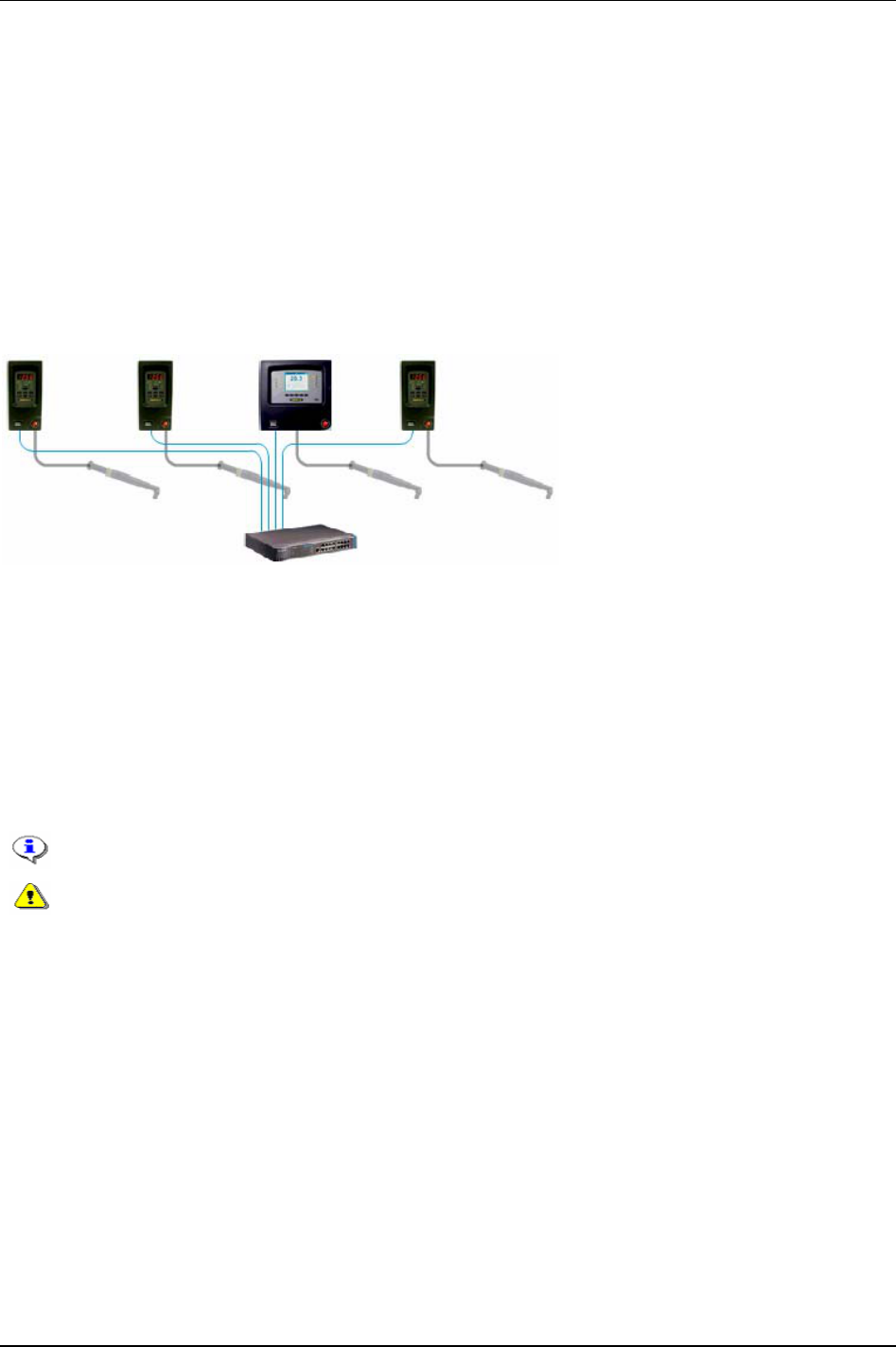
Controller
8.3.1 Cell and Net
The Power Focus software offers extended networking facilities. The Cell and Net concept is part of the
RBU gold and silver types.
EtherNet TCP/IP networking makes it simple to program and overview all PF units in the network from
a PC with ToolsTalk PF software installed. All data traffic from Power Focus could also be collected
and compiled by ToolsNet.
Via the Cell concept it is possible to arrange all PF units at an assembly station in a
Cell. The Net
concept enables functionality to group all Cells on the assembly line in one
Net.
The figure below illustrates a Cell consisting of three PF Compact controllers, one PF Graph controller
and a switch.
A Cell consists of one
Cell reference, a maximum of 19 Cell members and a total of 20 PF units. Cells
can then be grouped into
Nets; the maximum number of Cells in a Net is 1000. Each Net has a Net
reference
. One PF can function both as Cell reference and Net reference.
Every Cell has a Cell identification number (Cell ID) unique to the network. Within a Cell every PF has
its own unique channel identification number (Channel ID). With the PF Graph the user can browse
through the different channels and program and view the result from any other controller in the same
Cell.
The Cell reference and Cell members can be configured through a PF Graph user interface or ToolsTalk
PF.
All PF units in a Cell must have the same software version installed.
When configuring a remote PF, make sure it is not in use by anyone else. Otherwise it
might lead to the damaging of the tool or a joint. It might also lead to personal injury.
The RBU gold also enables Sync functionality (see chapter
Sync) and to run Cell Jobs (see chapter Job).
The figure below illustrates an example of a factory network configuration, a Net with three Cells. Each
Cell has a Cell reference and three Cell members. One Cell reference also functions as the Net
reference.
9836 3123 01 79 (330)
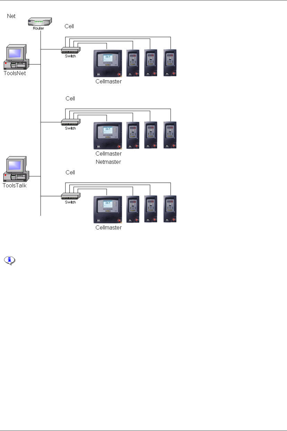
Controller
Network setup
This section includes screenshots from ToolsTalk PF. The screenshots shows examples of
parameter settings and is NOT intended to be generally applicable. Check with your
local Atlas Copco reprehensive how to set up your specific system environment.
Open the
Settings window from the menu bar.
In the serial setup section, select the
Com port to which the Power Focus is connected.
80 (330) 9836 3123 01
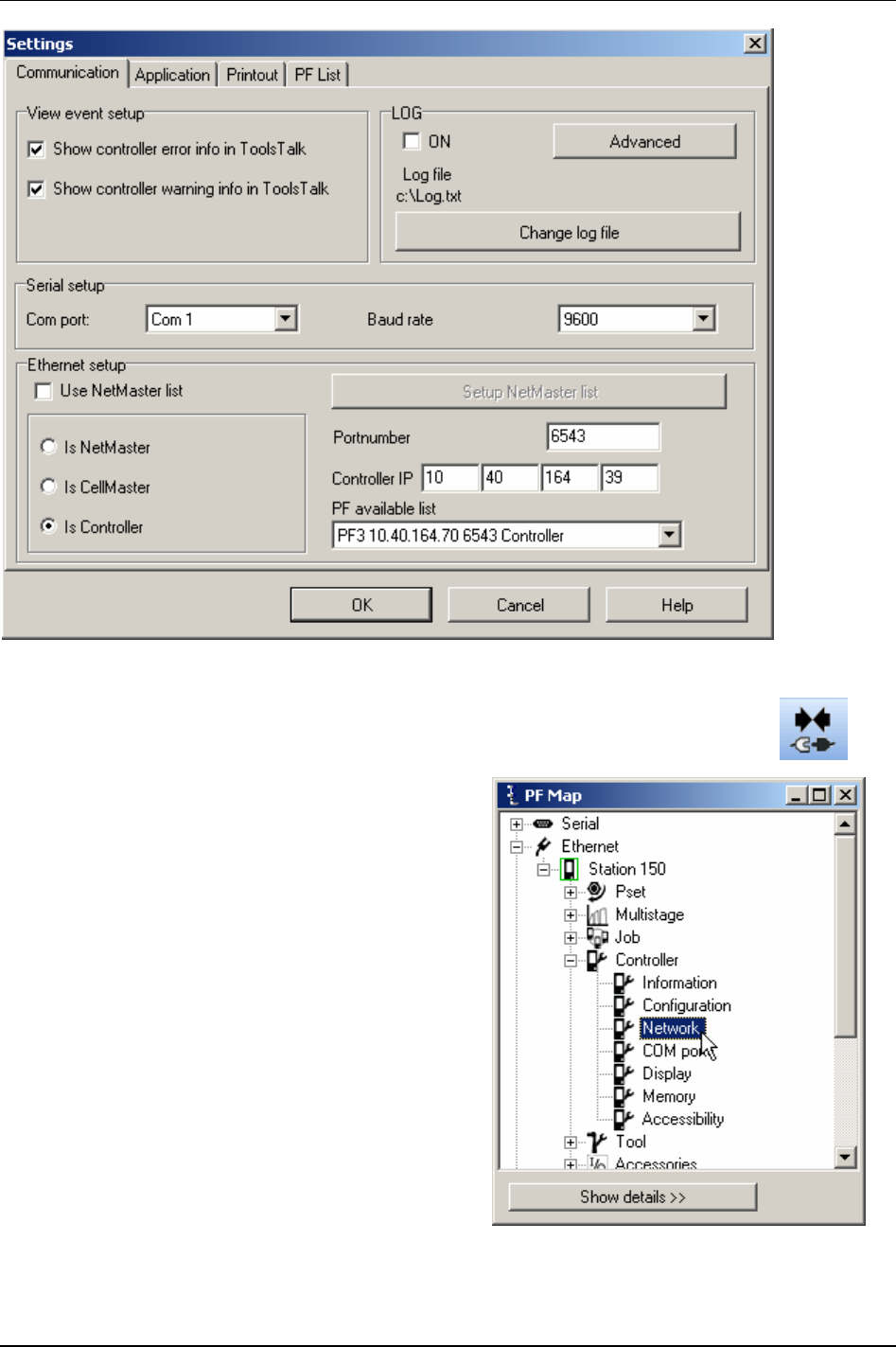
Controller
Connect the Power Focus by clicking the
Connect symbol.
In the PF Map
Controller branch, double-click on
Network.
9836 3123 01 81 (330)
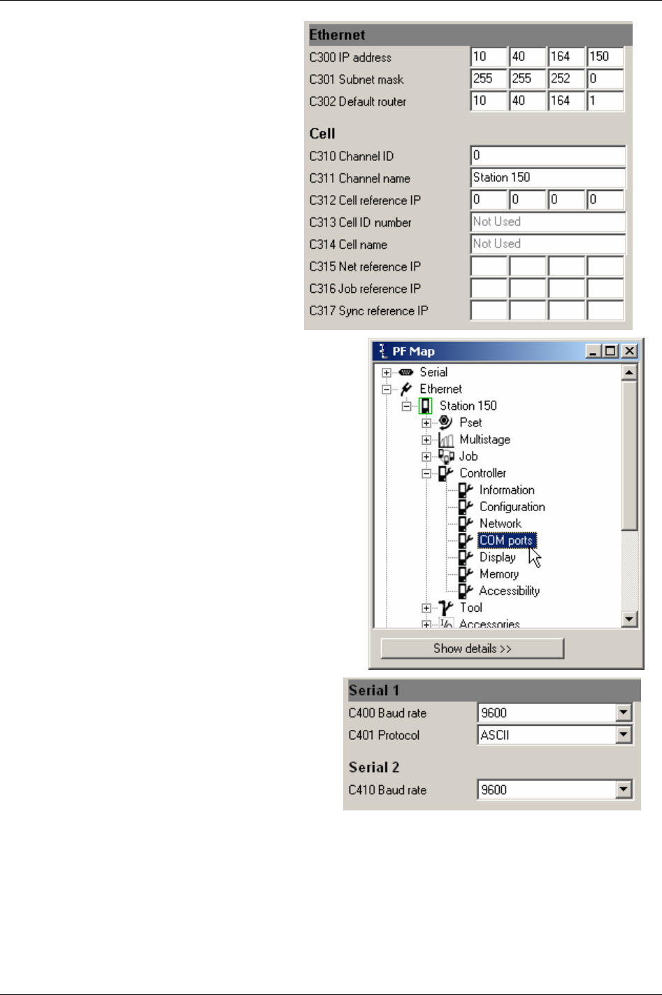
Controller
Set the IP address [C300] of the connected
Power Focus to a unique number within the
network.
Set the Subnet mask [C301] according to
network partitioning.
Default router [C302] is optional.
Click
Store to save settings.
In the PF Map
Controller branch, double-click on COM
ports.
The serial ports of the PF can be configured for
different baud rates.
Serial port 1 handles both ASCII and 3964R
communication.
Serial port 2 do only handle ASCII
communication.
Click
Store to save settings.
Restart the PF.
82 (330) 9836 3123 01
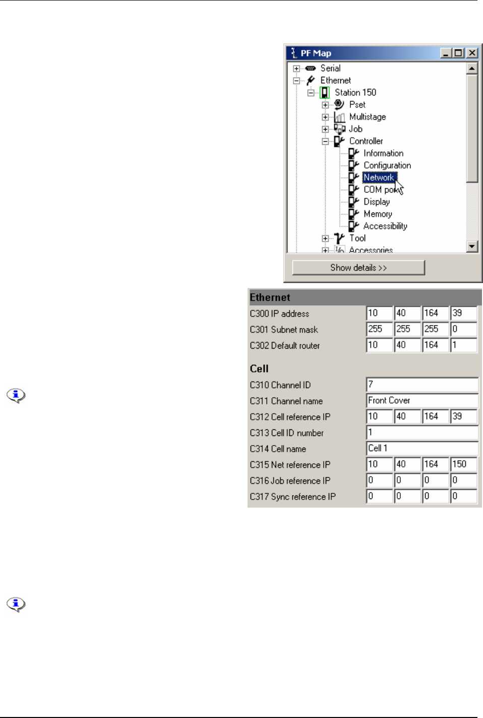
Controller
Cell and Net configuration
In the PF Map Controller branch, double-click on Network.
Set the IP address [C300], Subnet mask [C301] and
Default router [C302].
Set the
Cell reference IP [C312] to the IP address of the
Cell reference.
Set the
Net reference IP [C315] to the IP address of the
Net reference.
To define a Cell reference or Net
reference, set the Cell reference IP /Net
reference IP the same as its own IP
address.
Set
Channel ID [C310] to a number unique within the
Cell (1-20).
Channel name [C311] is optional.
Set
Cell ID number [C313] to a number unique within the network (1-1000). Only available when the
controller is the Cell reference.
Cell name [C314] is optional.
Click
Store to save the settings.
After all the settings have been made, restart all Power Focus units.
9836 3123 01 83 (330)
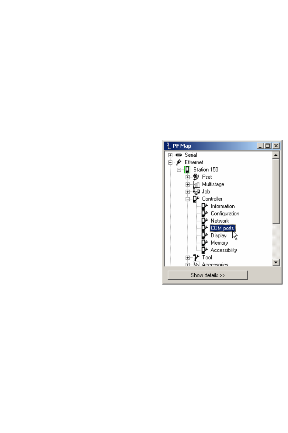
Controller
Power Focus connection
When connecting to a controller, Cell reference or Net reference make sure that the following settings are
correct.
Open
Settings (via options from the menu bar).
Set the
Controller IP address of the Power Focus to connect.
Under
EtherNet setup, check whether the connected Power Focus is a controller, Cell reference or a Net
reference.
To connect the PF, Cell reference or Net reference, click the
Connect symbol.
When a Cell reference or Net reference is connected, clicking the corresponding line in the
PF Map will
expand the Cell tree/ Net tree.
8.4 COM ports
In the PF Map Controller branch, double-click on COM
ports.
Make settings for
Serial 1 and Serial 2.
Click
Store to save settings.
84 (330) 9836 3123 01

Controller
8.5 Display
In the PF Map Controller branch, double-click on Display.
Make settings for Presentation, Result view,
Keyboard and Power save.
Click
Store to save settings.
9836 3123 01 85 (330)

Controller
8.6 Memory
All data stored in the PF, except parameters
IP address [C300], Subnet mask [C301] and Default
router [C302], will be erased when changing memory setup. Therefore, use ToolsTalk PF
function “Store PF to file” to save the existing data configuration (including Psets,
Multistages, and Jobs). The data can later be retrieved via function “Read PF from file”.
When changing the memory setup the PF must be rebooted for changes to take effect. It is
necessary to “Read PF from file” two times and reboot the PF one extra time.
It is recommended to reboot immediately.
Configurable memory is only available for RBU gold and silver.
Besides the default memory configuration, Power Focus provides six more configurable memory options;
More Psets, More Jobs, More Results, More Events, More Identifiers and Totally configurable (which gives
the possibility to manually configure the Power Focus memory).
Condition No. of
Psets
No. of
Jobs
No. of
Results
No. of
Events
No. of
Identifiers
No. of
Statistical
events
No. of
Identifier
result parts
No. of
Traces
Default configuration 250 99 5000 100 100 100 1 8
More Psets 300 100 4000 100 100 100 1 8
More Jobs 100 400 4000 100 100 100 1 8
More results 100 100 6000 100 100 100 1 8
More events 200 100 5000 500 100 100 1 8
More identifiers 200 100 5000 100 400 400 1 8
Totally configurable 1-300 1-700 1-9000 1-800 400 1-500 1-4 1-100
Number of identifiers is the maximum number of significant identifier strings available for identifier Type 1
(Identifier type 1 is used to trigger Psets, Multistages or Jobs).
Number of identifier result parts is the
amount of Identifier strings to be stored together with the tightening result. For more information, see
chapter
Identifier.
When increasing database elements, a decreasing of other elements might be necessary. For instance, if
6000 results are required it is not possible to have more than 100 Psets (option more results).
8.6.1 Store PF to file
Open ToolsTalk PF and connect to the PF.
In the
File drop down menu select Store PF to file.
A
Save as dialog box appears. State target, type name and
save the PF3000 text file (*.pf3).
A
Confirmation message will be displayed.
The “PF3000 Text file” should be used for the
restoring of data when the memory setup is done
(see section
Read PF from file).
86 (330) 9836 3123 01

Controller
Memory setup
In the PF Map, select Controller – Memory.
Make a selection for
Type [C600]. To manually configure the
memory, select
Totally configurable.
Click
OK to continue.
Select number of Psets, Jobs, Results,
Identifier result parts, Events, Statistical
events and Traces.
Indicator estimated memory
usage will automatically be
updated in percent (a
maximum of 100 percent is
allowed).
The changes made in
configurable memory setup will
reset the Power Focus memory
at the next reboot. All data
(tightenings results,
programmed Psets, Jobs, Sync
groups etc.) will be lost. The
only exception is parameters
IP
address [C300]
, Subnet mask
[C301]
and Default router [C302]
which will remain after the
reboot.
Use ToolsTalk PF function
“Store PF to file” to save the
existing data configuration
(including Psets, Multistages,
and Jobs). The data can later
be retrieved via function “Read
PF from file”.
9836 3123 01 87 (330)

Controller
Click Store to save settings.
When changing the memory setup the PF must be rebooted for changes to take effect. It is
recommended to reboot immediately.
Configurable memory is only available for RBU gold and silver.
After reboot, make a restore of the previous settings through function
Read PF from file, see section Read
PF from file.
8.6.2 Read PF from file
When memory setup is done, the PF3000 text file including the
previous data configuration (saved before setup) can be restored
into the PF again.
Command “Read PF from file” will overwrite current
programming and configuration in connected PF.
It is necessary to perform “Read PF from file” TWO
times and reboot the PF one extra time for changes to
take effect.
Open ToolsTalk PF and connect to the PF.
In the
File drop down menu select Read PF from file.
A
Confirm pop up window informs that
restoring from file will replace everything on
the controller.
Select Yes to continue.
Select
No to abort operation.
Read Selection window appears.
Select functions to restore. An unchecked box
means no replacement of data in that function
area.
Click
OK to confirm.
A
Confirm pop up window appears.
Select
Yes to keep present Power Focus name
and Network setup.
Select
No to restore Power Focus name and
network setup from file.
88 (330) 9836 3123 01
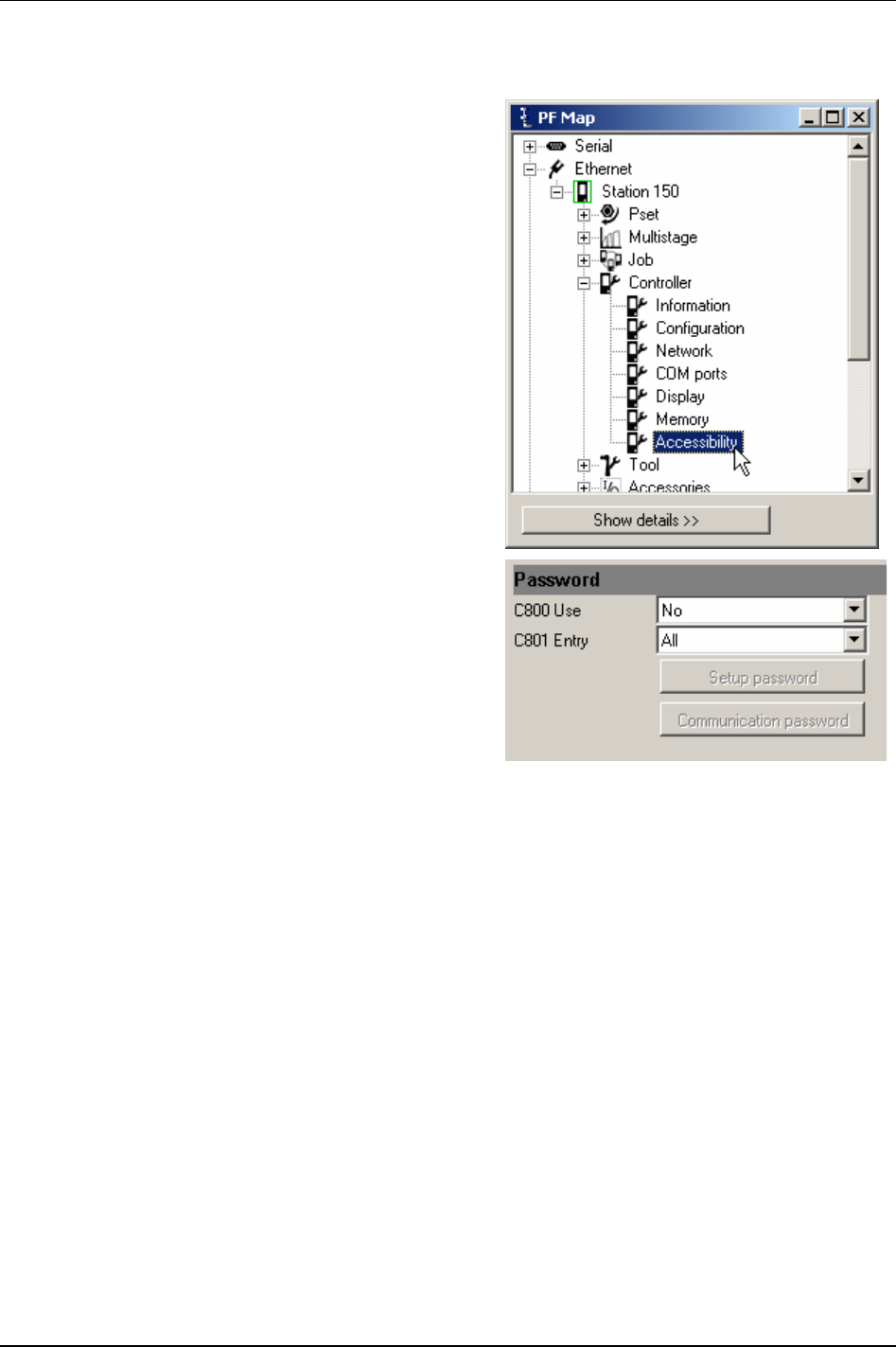
Controller
8.7 Accessibility
In the PF Map Controller branch, double-click on
Accessibility.
Make settings for Password.
Click
Store to save settings.
9836 3123 01 89 (330)
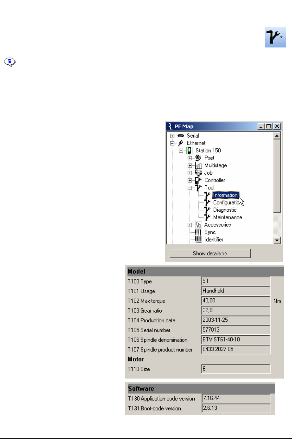
Tool
9 Tool
The Tool section contains information for Tensor tools connecting to the Power Focus.
Information from the PF containing general tool information, service status, hardware- and
software configuration etc.
This section includes screenshots from ToolsTalk PF. The screenshots shows examples of
parameter settings and is NOT intended to be generally applicable. Check with your
local Atlas Copco reprehensive how to set up your specific system environment.
See chapter
Parameter list for a description of all available Tool options.
9.1 Tool information
Expand the Tool branch in the PF Map.
Double-click on
Information.
The
Model and Motor sections contain
information about the Tensor tool
connected to the PF.
The
Software section contains information
about the application- and boot-code
version for the tool.
9836 3123 01 91 (330)
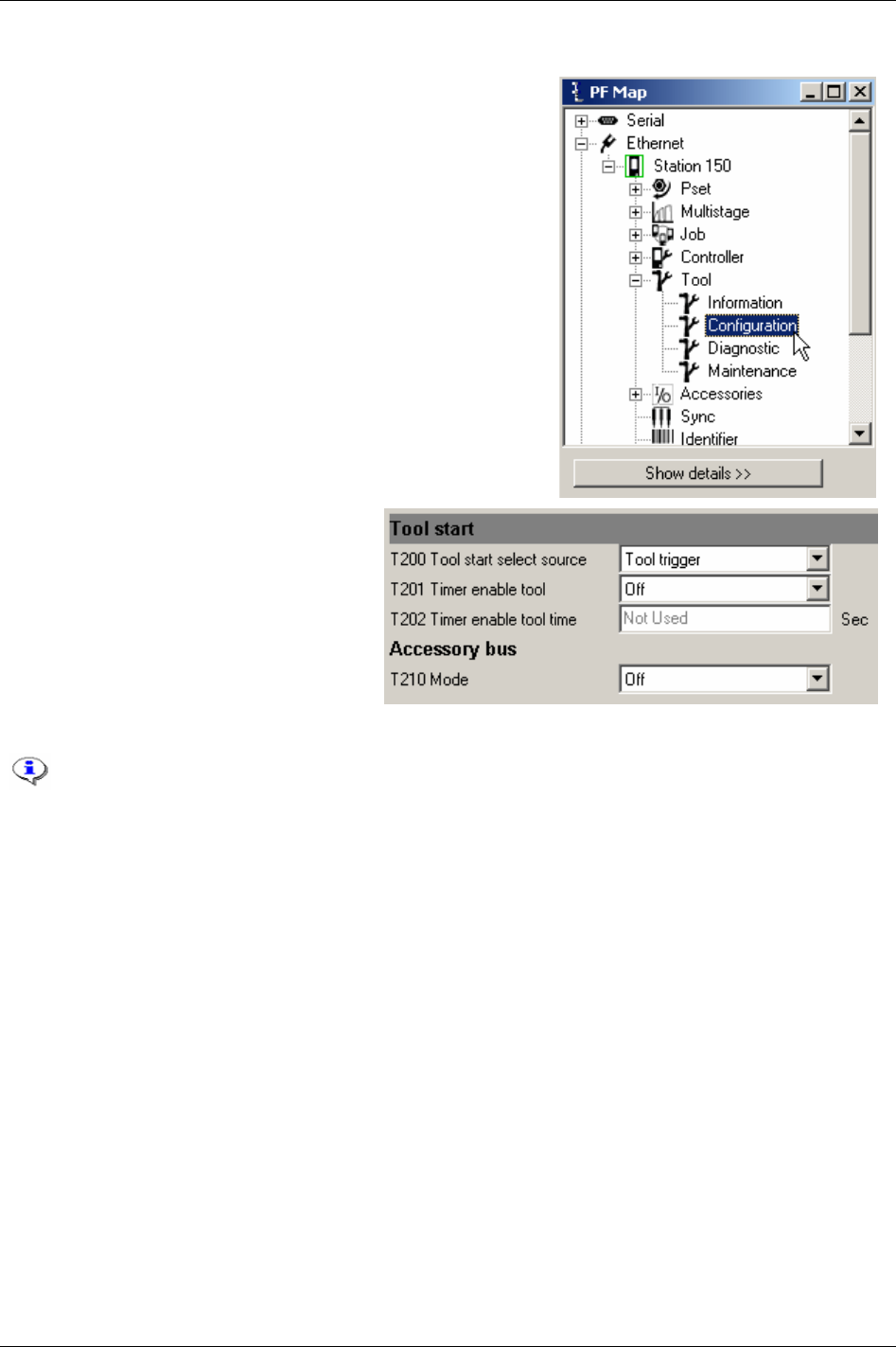
Tool
9.2 Tool configuration
In the PF Map Tool branch, double-click on Configuration.
Make settings for Tool start and Accessory
bus.
The main purpose for
Tool start select source
[T200]
option “Safety trigger” is to ensure
that both hands are placed on the tool while
it is running, and that the tool stops as soon
one hand is released. The safety trigger is
suitable for applications where a high level
of safety is desired.
The safety trigger function is only
available for ST tools
The safety trigger function requires the start trigger and safety trigger button to be pushed simultaneously
in order to start the tool. The second button must be pushed within 0.5 s from the first button, order is
arbitrary. If the safety trigger button or the start trigger is released while the tool is running, the tool will
stop immediately.
Once the tool has been started, the safety trigger function requires both buttons to be released before the
tool can be started again.
A safety trigger button is mounted on the ST tool and connected to GPIO 4. The parameter is only
accessible when GPIO 4 is set to “off”.
The main purpose of the
Timer enable tool [T201] function is to prevent unintentional starting of the tool. It
is immune to tape, i.e. it is not possible to override the function by putting tape on the “enable button”.
The timer enable tool is suitable for applications where a reasonable level of safety is required and
applications where both hands cannot remain on the tool during tightening (one hand must be used to
hold the working piece during tightening etc).
When the
Timer enable tool [T201] is activated, the tool will be disabled by default. In order to enable the
tool, the user must enable the tool using the digital input function “timer enable tool”.
Once enabled, the tool will remain enabled for the configured period of time (timer enable tool time). As
soon as the time period expires, the tool will be disabled again.
92 (330) 9836 3123 01
Tool
If the tool is started during the period it is enabled, it will remain enabled while it is being run. When the
tool is stopped, it will remain enabled for an additional period of time (according to release and
configuration). This behaviour is comparable to key lock functionality on cellular phones; once
unlocked, the keys will be locked when a given period of time has passed since the last key press.
The “timer enable tool” function was previously called “safety trigger”.
Digital input “timer enable tool” must be changed from status “low” to “high” in order to
enable the tool (the tool will not remain enabled when the time period has expired, even if
input to the digital input “timer enable tool” remains high ).
Parameter
Mode [T210] is for ST selector configuration. The selector has two different modes, mode 1 and
mode 2. In Mode 1 the selector only utilises the tool accessory bus as GPIO. This mode only supports a
maximum of 15 Psets (1-15). In Mode 2 the selector is a true ST accessory taking full advantage of the
bus capabilities.
Keep the left button on the selector pressed when powering up (this is done by hot swapping the tool or
powering up the PF). The selector will now enter the configuration mode.
Press the right button on the selector to toggle between mode 1 and 2. Confirm mode selection by
pressing the left button.
Mode 1 is primarily intended for use with the Power Focus world 3 software release and
later. Mode 2 is recommended for users with Power Focus world 5 software releases.
If “Mode 1” is selected the number of Psets (1-15) to use must now be set. Press
the right button to select the number of Psets to use. Use the left button to
confirm. The selector is now ready to use. When using mode 1 the
Mode [T210]
must be set to “GPIO” with the GPIO device configured according to the table to
the right. Parameter
Pset select source [C200] must also be set to “DigIn”.
Pin Function (input)
4 Pset Select bit 3
3 Pset Select bit 2
2 Pset Select bit 1
1 Pset Select bit 0
If “Mode 2”is selected the
Mode [T210] must be set to “ST bus”. Parameter Pset select source [C200] also
must be set to “ST selector”. The selector has a number of configurable parameters (see table below).
Selector parameter Selections
Left button and right button Off: button disabled.
Next Pset: select next Pset.
Previous Pset: select previous Pset.
LED status Off and On
Display
(1)
Off: display disabled.
Pset no.: displays selected Pset number.
Pset target: displays selected Pset target value (torque or angle).
Result: displays the tightening result.
Pset no. + result: toggles between Pset number and tightening result
(2)
.
Pset target + result: toggles between Pset target and tightening result
(2)
.
Pset no. + Pset target: toggles between Pset number and target
(2)
.
Pset no. + Pset target + result: toggles between Pset number, target and tightening result
(2)
.
(1)
Event codes always displayed, except for “Off“
(2)
The Pset number (or Pset target) is displayed until a tightening result is generated. The tightening
result is displayed until the next tightening is started or a new Pset is selected. In mode “Pset no. + Pset
target” the Pset number and target toggle will show on the display until a result is generated.
9836 3123 01 93 (330)
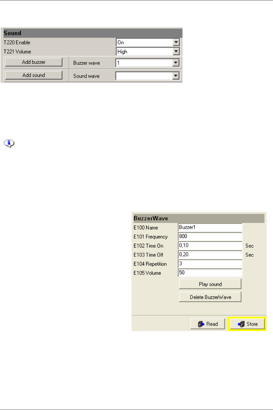
Tool
Make settings for Sound.
Enable/disable sound and adjust the
Volume [T220] (low, medium or high).
Two types of sound files can be stored in the Power Focus memory, buzzer and sound (stream) waves. A
Buzzer wave is a frequency-based sound generated by the tool. The buzzer wave can be programmed by
the user (as default one wave is included in Power Focus). A
Sound (stream) wave is a pre-programmed
“wav file” that can be downloaded from disk (hard drive/ file). It is possible to use a microphone to
record wav files and download them to Power Focus.
ST tools support sound and buzzer functionality.
STB and SL tools support only buzzer functionality.
S and ETX tools do not support sound and buzzer functionality.
To select an existing buzzer wave, select an
ID number from the drop down menu (as default one buzzer
wave is included).
To create a new buzzer wave, click
Add buzzer. It is possible to store up to 10 buzzer waves in Power
Focus.
The
BuzzerWave window appears.
Give the Buzzer wave a
Name [E100] (optional).
Select
Frequency [E101] (400-4000 Hz), Time On
[E102]
(0.01-65.0 Seconds), Time Off [E103] (0.01-
65.0 Seconds),
Repetition [E104] (0-100 times) and
Volume [E105] (0-100 %). The volume is a relative
(in percent) parameter
Volume [T221], which could
be set to high, medium or low.
Volume [T221] can
be found in the sound setup window.
After every change in setup, click
Store to save
settings into the tool memory. Even if a value is
within specified limit it could be coloured red.
Click
Store and it will turn to black.
Click
Play sound to listen to the buzzer sound in
the tool (if not working, try to click
Store).
Click
Delete buzzer wave to remove the selected
buzzer. Click
Store to save settings.
94 (330) 9836 3123 01
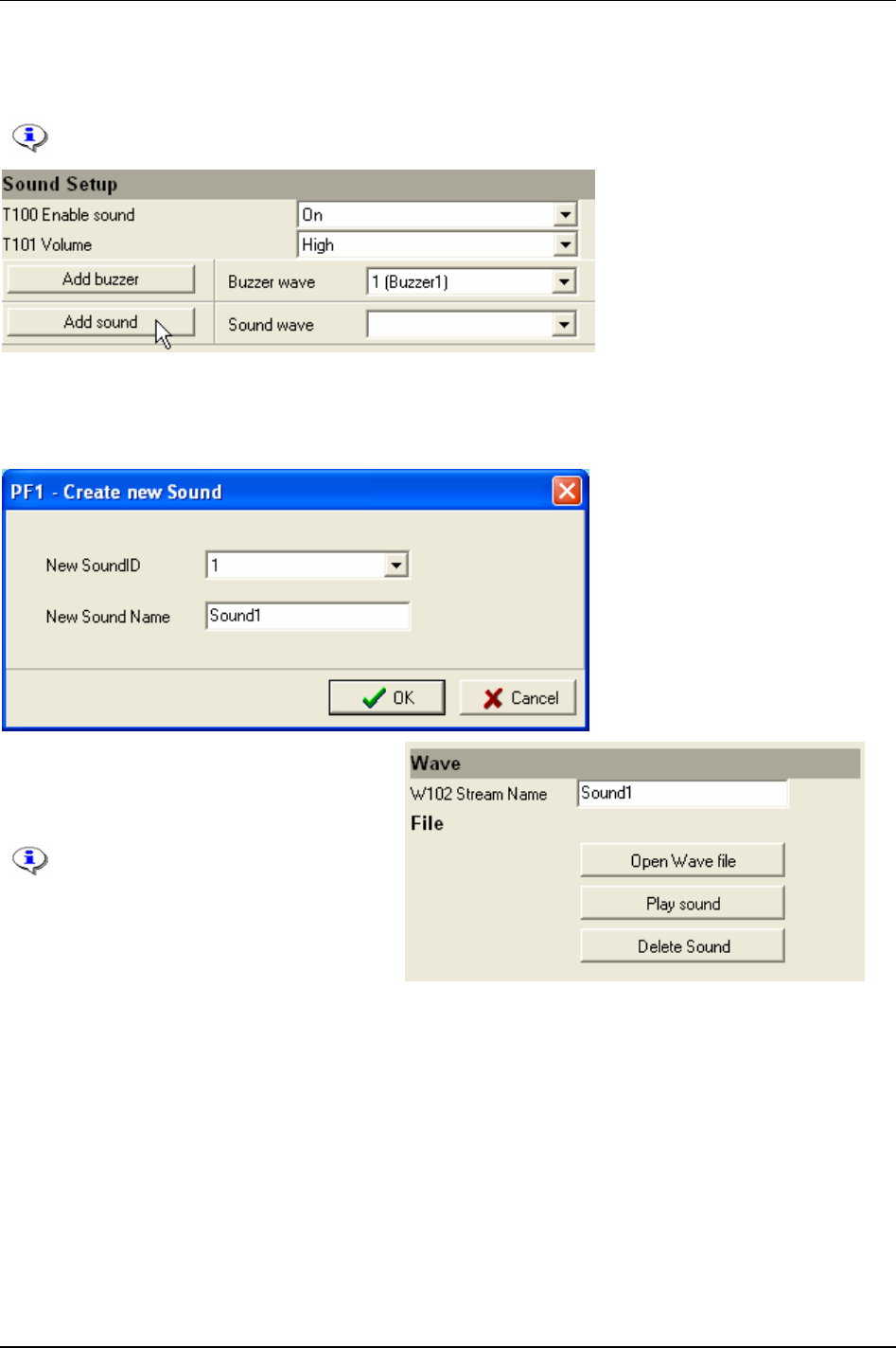
Tool
To create a sound (stream) wave, select Add sound in the Sound window. To select an existing Sound
wave, select an
ID number from the drop down menu.
It is possible to store up to 10 stream waves in Power Focus.
The
Create new sound window appears.
Select a
New sound ID and type new sound name (optional).
Click
OK.
The
Wave window appears.
Click
Open wave file and search for the wave
file to use on disk (hard drive/file).
The wav file can use up to 8 bits and
a frequency of up to 8000 Hz. It
provides only mono playing and has
an interval of maximum 3 seconds.
Click
Play sound to listen to a sound file. The
sound will be played in the tool.
Click
Delete sound to remove a sound file.
Click
Store to save settings.
Close window.
9836 3123 01 95 (330)
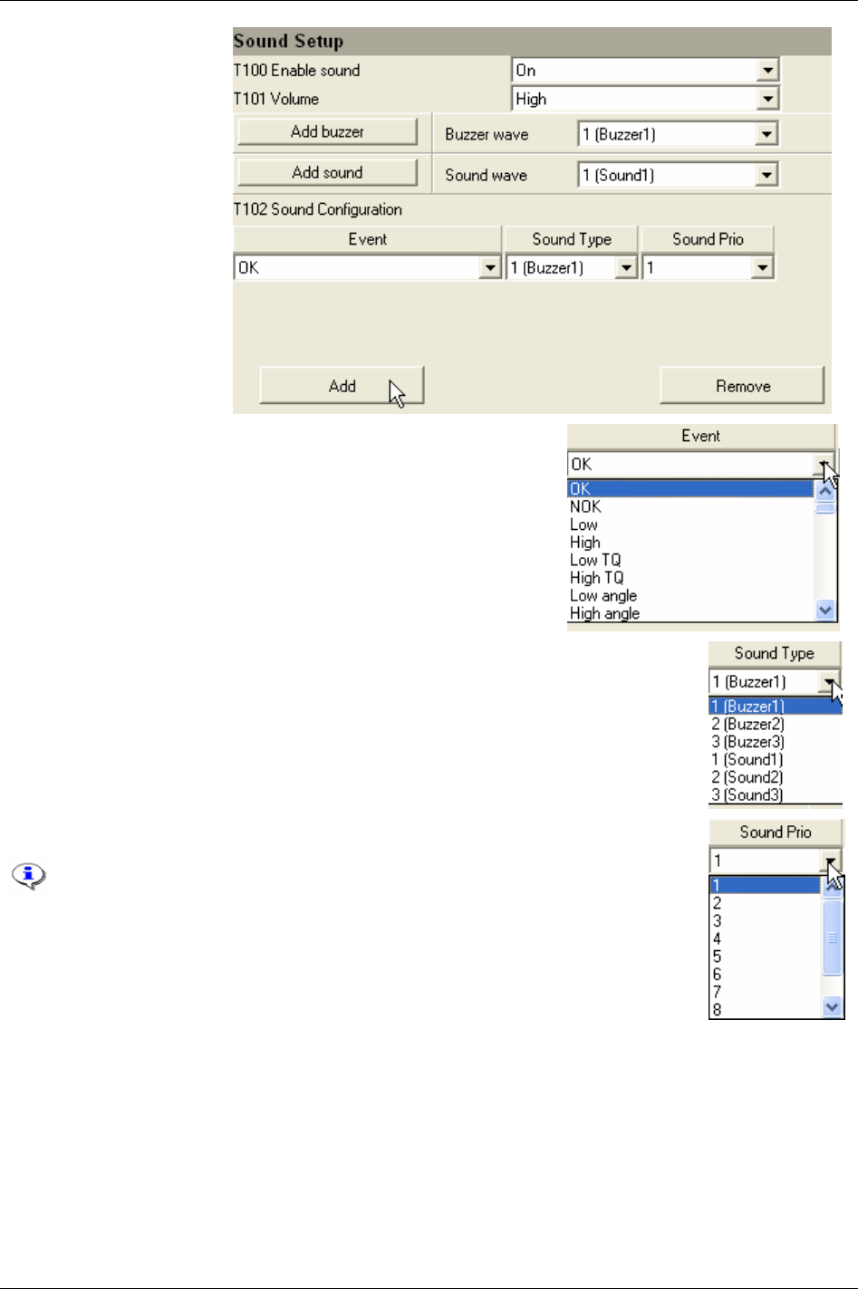
Tool
In the Sound setup
window, click
Add.
Select a digital relays in the
Event list. For available relays, see
chapter
Digital inputs and outputs.
Select a sound or buzzer wave (crated earlier) in the
Sound Type list to connect to the
event.
Select a priority from the Sound Prio list connected to the specific sound event.
The priority decides which sound event has the advantage in the case of a
collision between more than one sound file during tool operations.
Click
Remove to remove an event from the list.
Click Store to save changes in the Window.
96 (330) 9836 3123 01
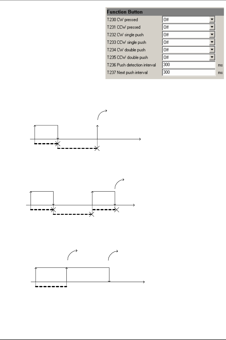
Tool
Make settings for Function buttons.
The
Function buttons [T230 – T235] are available
for ST and SL tools. There are three possible
user interaction types for this button; single
push, double-push and pressed. (For available
relay functions, see chapter
Digital inputs and
outputs
.)
The parameter
Push detection interval [T236]
states the maximum time (in milliseconds)
between the button pressed to the button being
released for push to be detected. Parameter
Next
push interval [T237]
states the maximum time (in
milliseconds) between the button being released
after the first push and the button pressed again
to detect double pushed.
Button pressed
Button released
Push detection interval
Next push interval
Time
Timeout
Single push
Single push
- the button is pressed down and released before the Push detection interval [T236] expires. The
Next push interval [T237] expires before the button is pressed again.
Button pressed
Button released
Next push interval
Time
Button pressed
Button released
Push detection interval
Double push
Push detection interval
Double push
- the button is pressed down and released before the Push detection interval [T236] expires.
Then the button is pressed down before the
Next push interval [T237] expires and is released before the
Push detection interval [T236] expires.
Button pressed
Button released
Push detection interval
Time
Pressed
Timeout
Released
Pressed
- the button is pressed down and is kept down for a longer time than the Push detection interval
[T236]. When the Push detection interval expires, the button function is considered to be pressed until it is
released. Notice that if no function is configured for single push or double push in the current tool
direction, the
Push detection interval will be ignored and the button function is considered to be pressed as
soon as it is pressed down.
9836 3123 01 97 (330)
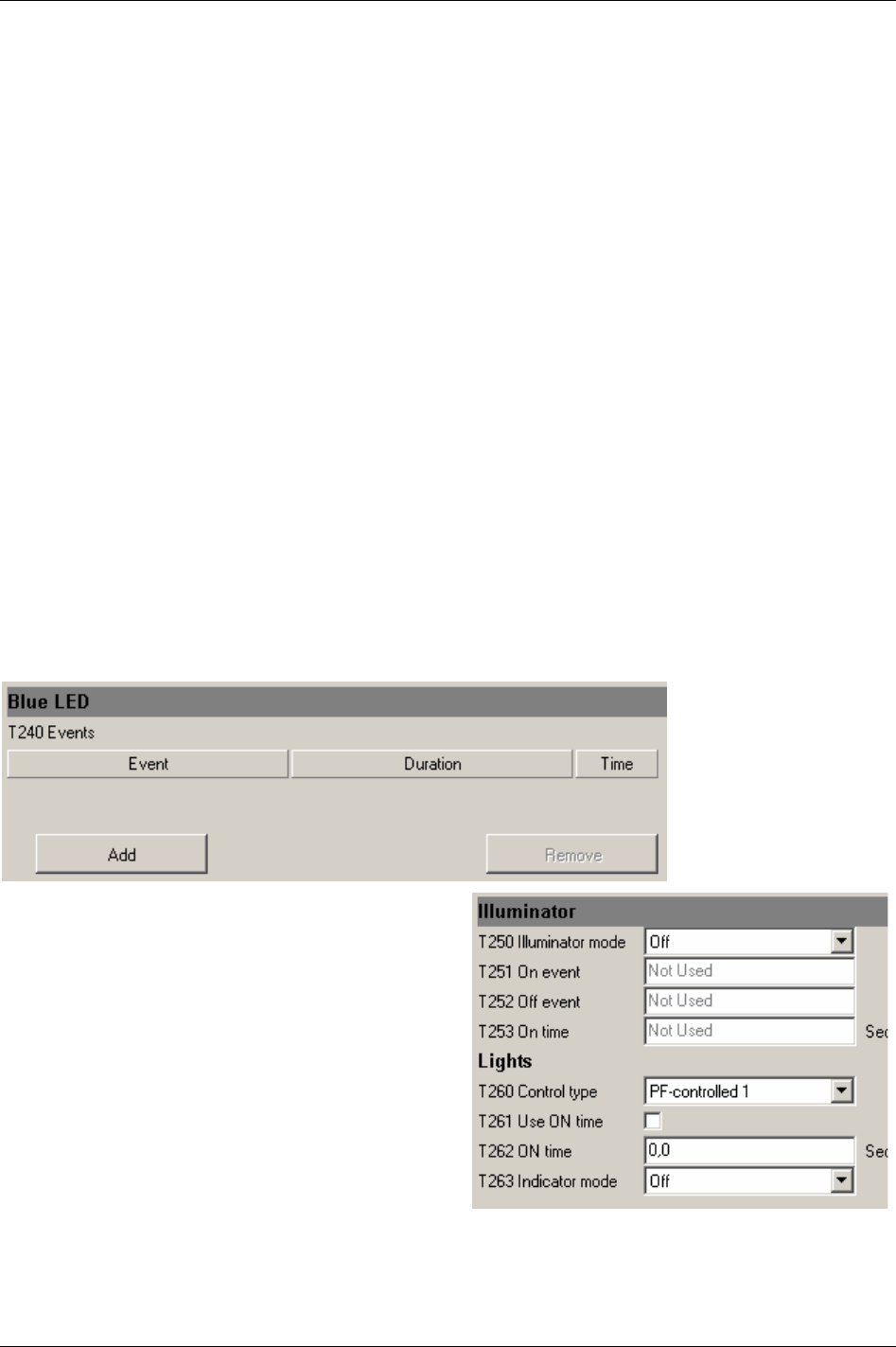
Tool
It is possible to configure a digital input function, similar to the digital inputs on the PF, for each user
interaction type and tool direction. Tool direction is shown by the direction ring on ST tools and by the
direction LED on SL and DL tools.
From the digital input functions point of view, single push and double push user interaction types do
generate pulses. This means that they do not have duration where input to the digital input function
remains high.
Single push and Double push user interaction types are therefore not suitable for digital
input functions that are intended to “follow” the status of the button. The
pressed user interaction type
does provide duration; input to the digital input function remains high as long as the function button is
pressed and becomes low when it is released. It can therefore be used with digital input functions
intended to follow the button status.
Feedback is provided to the user to indicate which user interaction type was detected. If a
Single push is
detected, the tool LED’s will flash once and if a
Double push is detected, the tool LED’s will flash twice.
Feedback is only given when there is a function configured for the currently performed user interaction
type and current direction. For example, if a
Double push is performed while operating in CCW mode,
but
CCW double push [T235] is set to “off”, no response will be given.
For SL and DL tools, the function button will normally be configured to change tool direction in some
way (“toggle CW/CCW”, “toggle CW/CCW for next run” and “set CCW”).
Make settings for Blue LED. The Blue LED on the ST tool indicates when a predefined event occurs. The
events are relays connected from Power Focus to the tool.
To configure the
Events [T240] click Add.
Select type of
Event. For available relays, see chapter Digital inputs and outputs.
Select
Duration (to next tightening, tracking event or time).
Click
Store to save settings.
Make settings for
Illuminator and Lights.
The illuminator, which is a group of LED’s in the
front of SL/DL and ST pistol tools, provides light for
the operator during tool operations.
The parameter
Illuminator mode [T250] can be set to:
Off - illuminator is constantly off.
On - illuminator is constantly on.
Tracking event - illuminator follows status of
specified
On event [T251].
Event controlled - illuminator is turned on when
specified
On event [T251] occurs and is turned off
when specified
Off event [T252] occurs. If Off event
is set to “of”, the expiration of
On time [T253] will
turn off the illuminator.
98 (330) 9836 3123 01
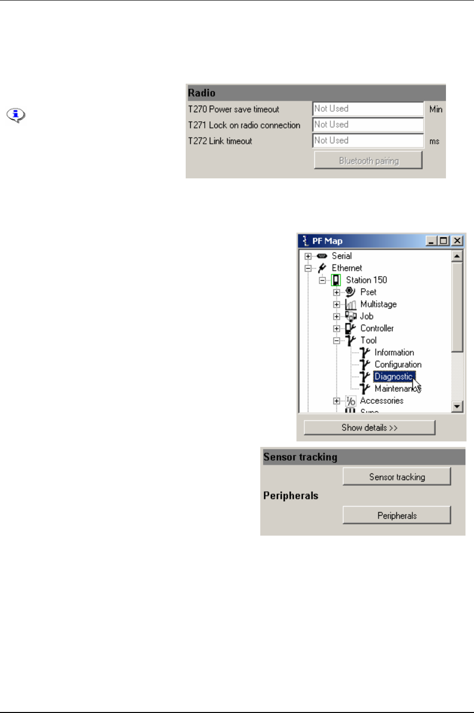
Tool
The parameters On event [251], Off event [T252] and On time [T253] are related to the input from the
Illuminator mode [T250].
Maximum time for the illuminator to remain on since the last occurrence of
On event [T251].
For available relay functions, see chapter
Digital inputs and outputs.
Make settings for
Radio.
This section is for
configuration of STB tools.
For more information, see
chapter
Tensor tools and
chapter
Parameter list.
Click
Store to save settings.
9.3 Tool diagnostic
In the PF Map Tool branch, double-click on Diagnostic.
Click Sensor tracking to introduce torque and angle
readings in real time.
Click Peripherals to diagnose tool LED's and buttons.
9836 3123 01 99 (330)
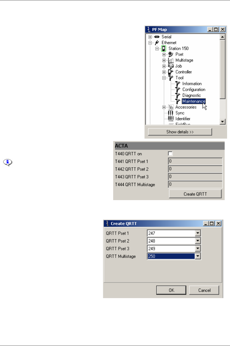
Tool
9.4 Tool maintenance
In the PF Map Tool branch, double-click on Maintenance.
The t ACTA section contains a tool calibration
session.
The calibration will not work with
Tensor DS tools.
A tool calibration session is started by connecting
the ACTA 3000 to the Power Focus and fitting the
QRTT device to the spindle. One Multistage with
three Psets is used when the calibration is run, one
torque tightening (for torque calibration) and two
different spindle rotations (for loosening and angle
calibration) Psets.
Click
Create QRTT to create the Psets and
Multistages needed. The target torque and
angle is then set by the ACTA 3000 before
the start of each calibration.
The tool calibration is started by a command
from the ACTA 3000 or by pressing the tool
trigger depending on if the tool is configured
for remote start or not. The result of a
calibration is displayed as a normal
tightening. When a calibration batch is
completed, event code
ACTA/QRTT calibration
[E710]
is displayed and stored in the event log
of the Power Focus.
It is necessary for the Power Focus to have enough memory space available to store the Multistages and
Psets needed. If the calibration shows an unsatisfactory result the operator is assumed to take the
appropriate action. No calibration value (calibration- or normalisation value etc.) will be changed
automatically.
100 (330) 9836 3123 01
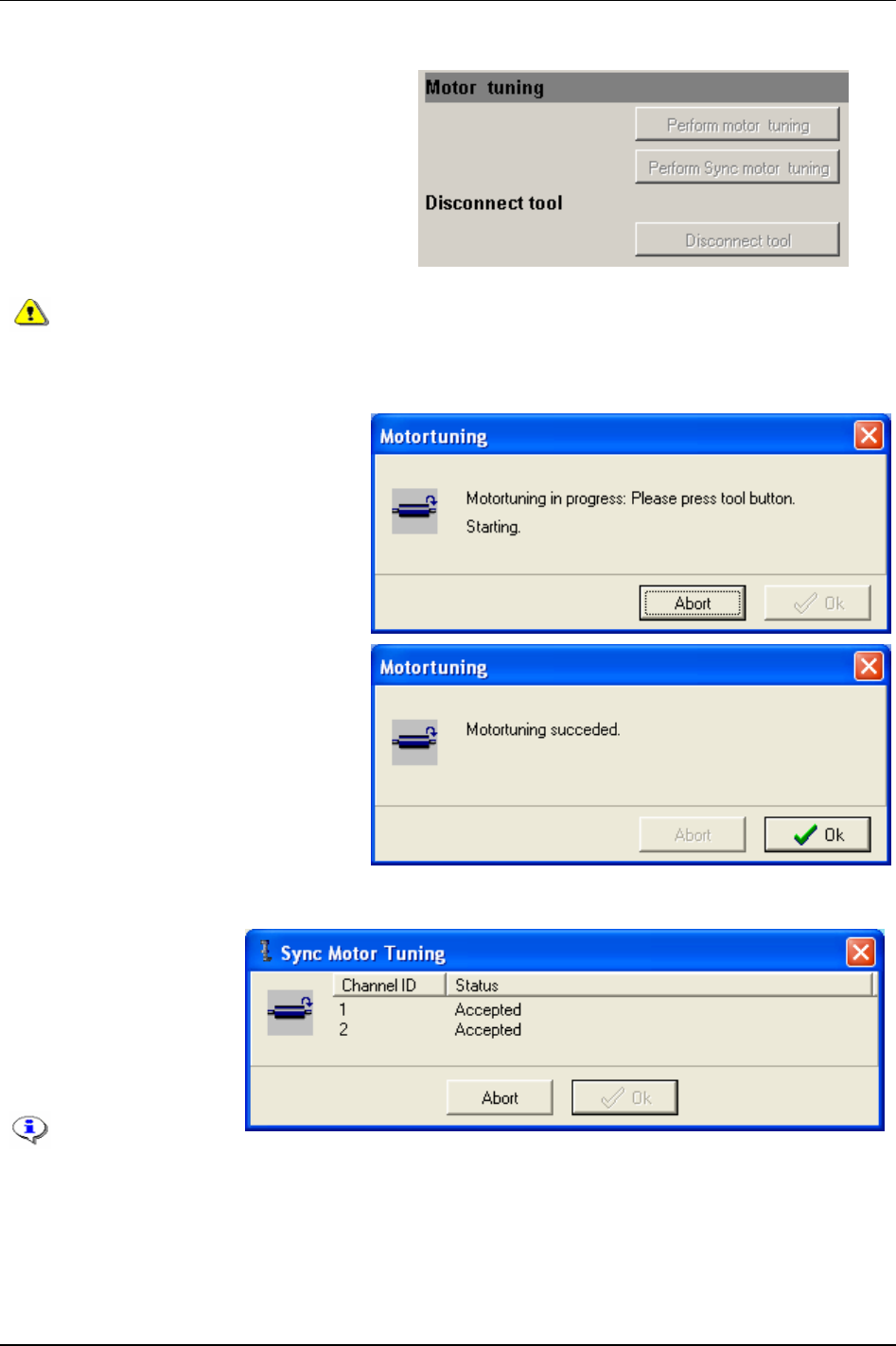
Tool
9.4.1 Motor tuning
Motor tuning adjusts the tool and motor control
unit.
Sync motor tuning feature is only available
from the Sync reference of a configured Sync
group with between two and ten Sync members.
The Sync motor tuning process starts
simultaneously for all Sync members when
pressing the tool trigger of the Sync reference.
For information about the Sync functionality
see chapter
Sync.
It is important that no torque is applied to the socket of the tool when it is subject to any
kind of motor tuning. Make sure that the socket is able to rotate freely.
Standalone motor tuning
Click Do motor tuning.
Press
Tool trigger and keep it pushed
during the motor tuning process (the
status will be displayed).
Release
Tool trigger or click Abort to
cancel.
When finished the result of the motor
tuning is displayed.
Sync motor tuning
Click Sync motor tuning.
Push
Tool trigger and keep
it pushed during the motor
tuning process.
Release Tool trigger or
click
Abort to cancel.
Accessing Sync
motor tuning is
only allowed on a
Sync reference.
9836 3123 01 101 (330)
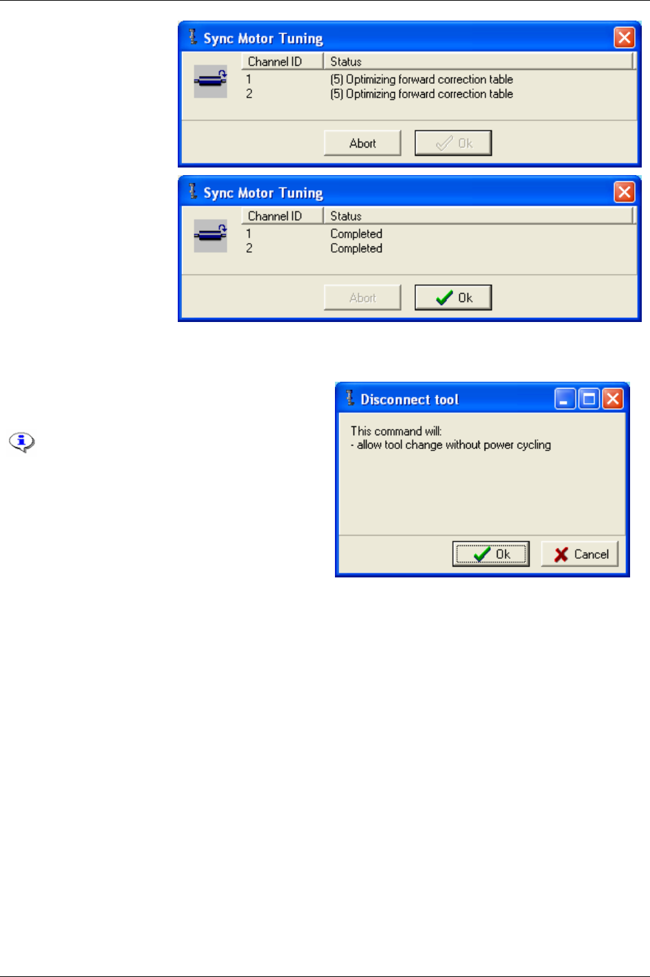
Tool
Channel ID and motur
tuning status for Sync
refernce and all Sync
members are displayed.
When finished the result of
the motor tuning is
displayed.
9.4.2 Disconnect tool
Click Disconnect tool and click OK to logically
disconnect the tool.
Do not disconnect a tool during tightening,
loosening, positioning, motor tuning, Open
end tuning or tracking.
Logical disconnection is not necessary for
ST and SL/DL tools (this tool types allows
hot swap functionality).
If the operation succeeded, the green OK LED will flash continuously (on the Power Focus) and the
message “command accepted” will be displayed. Click
OK to continue.
If disconnection of the tool was not allowed, the red NOK LED will flash continuously for 3 seconds and
the text “operation failed” will be displayed on the display. Click
OK to continue.
When a tool is inserted again,
Tool disconnected [E131] will be displayed and then acknowledged
automatically.
In order to be able to use digital I/O to disconnect the tool, one digital input must be configured as
“disconnect tool” and optionally one relay can be configured as ”safe to disconnect tool”.
Once configured, proceed as following to logically disconnect the tool using digital I/O:
Set voltage level on the digital input (configured as “disconnect tool”) to high in order to logically
disconnect the tool.
If the operation succeeded, the relay configured as “safe to disconnect tool” switches and the green
OK LED (on the PF) will flash continuously. If disconnection of the tool was not allowed, the relay
configured as “safe to disconnect tool” will not switch and the red NOK LED will flash continuously
for 3 seconds.
Disconnect the tool.
102 (330) 9836 3123 01
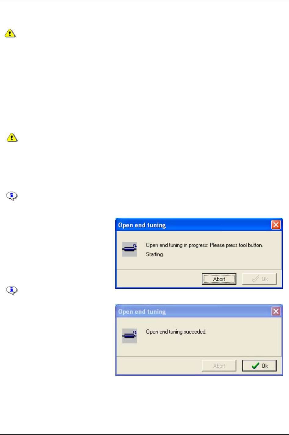
Tool
When a tool is inserted again, Tool disconnected [E131] will be displayed and then acknowledged
automatically.
Do not physically disconnect an S or DS tool, unless it has first been successfully logically
disconnected. That may damage the tool memory. If the user physically disconnects a
non-ST tool, without a successfully logically disconnection, the PF has to be rebooted
before connecting the tool again.
9.4.3 Open end tuning
For ST and SL tools it is not possible to change the Open end parameters.
For S and DS tools, use parameter
Use open end [T420] to activate the Open end functionality.
Inverted motor rotation [T421] should be checked if an Open end head is used which changes the rotation
direction of the spindle.
If the
Inverted motor rotation [T421] is set in the wrong way the tool may not operate in a
correct manner and the mechanical stop may be damaged if a tightening is done.
Set
Open end tightening direction [T422] to the direction that fits the application and Open end head. “CW”
is selected for right hand threaded fasteners and “CCW” for left hand threaded. This setting is valid for
all programmed Psets.
Parameter
Tool tightening direction [P240] has no effect when running an Open end tool.
When finished with parameter settings, press
Store.
Click
Open end tune key in the Open
end parameters section.
Make sure the Open end head can rotate
freely and press the tool trigger.
Open end tuning measures the gear
ratio and gear play and stores it to the
tool memory.
The old
Gear ratio [T103] value
will be overwritten.
A confirmation message is displayed if
Open end tuning succeeded.
9836 3123 01 103 (330)

Tool
104 (330) 9836 3123 01
9.4.4 Tool lock functionality
The tool may be locked either by an internal state that does not allow the tool to be used, or intentionally
by configurable functions in the Power Focus and external sources.
Locking of tools from an external source in time critical applications
When the Power Focus is used in line assemblies the tightenings are often controlled carefully. The users
wish to ensure that all tightenings are performed on the correct joints. For that reason the users wish to
lock the tool frequently between the different tightenings on a work piece within a workstation. Often such
applications are also time critical, meaning that the operator has to perform a number of tightenings within
a short time span. In such cases there is a high risk of obtaining a poor tightening result when locking the
tool from an external source, such as via Field bus, the open protocol or the ToolsTalk PF protocol.
The reason for the problems is that by using the mentioned sources for tool locking; the tool is not actually
locked until several hundred milliseconds after the triggering event (such triggering events are e.g.
controlled by tool positioning systems etc.). Commonly used commands are ”Tool disable” and “tool
enable” functions in the table in section Error! Reference source not found.. Within a time frame of 100-
200 ms the operator may push the tool trigger many times, which destroys the purpose of carefully
controlled tightenings.
Therefore, the usage of the listed external sources for locking the tool frequently in time critical
applications is not recommended. In order to lock the tool quickly enough in these cases only Power Focus
internal sources should be applied (i.e. 1-2 ms reaction time).
In a lot of applications suffering from these problems the following general strategy could be used:
For enabling the tool, use the external source for selecting the Pset in Power Focus when the conditions
for “start tightening” are fulfilled.
For disabling the tool, use functions
Lock at batch ok [P152] or Lock at Job done [J302], which are internal
tool locking sources within Power Focus.
Intentional locking of tools
By locking and unlocking the tool in certain situations, it is possible to prevent unintended usage of it. In
this way it is possible to avoid some of the mistakes that could normally be made during assembly.
Definition of a locked tool
When the tool is locked, one or several services are disabled. Services are normally tightening and
loosening, but do in some cases (see below) include positioning, motor tuning, Open end tuning and
tracking.
Event codes
In case the tool is locked while a user attempts to start a service (normally tightening or loosening), the
Power Focus will show an event code to explain why or by which functionality the tool is locked. In case
the tool becomes locked while a service is being performed, the service will be aborted and an event code
explaining why or by which function the tool was locked will be displayed.

Tool
9836 3123 01 105 (330)
Internal states/conditions
Reason Event
code
Lock trigger Unlock trigger Affected services Comments
Event code to
acknowledge
n/a * An event that must be
acknowledged occurs
and the corresponding
event code message is
displayed.
The event code
message is
acknowledged.
Tightening, loosening,
positioning, motor
tuning, Open end
tuning and tracking; all
combined.
* See chapter Event
codes
to view events
that must be
acknowledged.
RBU
disconnected
E117 Disconnection of the
RBU is detected.
The Power Focus is
turned off, a (healthy)
RBU is inserted and
the Power Focus is
turned on again.
Tightening and
loosening combined.
Requires a restart of
the PF.
Tool
disconnected
E131 The tool is disconnected
from the PF.
The tool is
reconnected to the PF.
Tightening, loosening,
positioning, motor
tuning, Open end
tuning and tracking; all
combined.
Event code messages
are generated when
attempts to perform
tightening or
loosening are made
from an external
source while the tool
is disconnected.
Tool locked
during work
order
E141 Tool is locked during
work order.
All expected
identifiers have been
received in correct
order.
Tightening and
loosening combined.
See chapter Identifier.
No tool cable
detected
E146 A tool is used, but the
tool cable can not be
detected.
The tool cable is
detected.
Tightening, loosening,
motor tuning, Open
end tuning and
tracking; all combined.
ST tool cable can not
be detected missing
when S/DS tool is
used.
Click wrench
Pset in use
E147 A Pset with click wrench
tightening strategy is
selected.
A valid non click
wrench strategy Pset
is selected.
Tightening and
loosening combined.
Invalid Pset
number selected
E206 Invalid Pset number
selected.
Valid Pset number is
selected.
Tightening and
loosening combined.
Tool overheated E501 The tool is hotter than
allowed.
The tool is colder than
maximum allowed
temperature.
Tightening, loosening,
positioning, motor
tuning, Open end
tuning; all combined.
Let the tool rest until
it is cold enough to
run.
Tool size
mismatch
E511 Mismatch between the
tool and the controller
(for example S4/S7 tool
connected to a S9
controller)
A match between tool
and controller is
detected.
Tightening, loosening,
positioning, motor
tuning, Open end
tuning and tracking; all
combined.
Motor tuning
information
incorrect
E514 The motor tuning
information in the tool is
not correct (has a bad
check sum).
The motor tuning
information in the
tool is correct (has a
correct check sum).
This should be the
case after a successful
motor tuning.
Tightening, loosening,
positioning, motor
tuning, Open end
tuning; all combined.
Perform a motor
tuning if this event
code occurs.
Sync member
registration
failure
E870 Sync member
registration failed.
Sync member
registration
accomplished
successfully.
Tightening, loosening,
motor tuning, Open
end tuning and
tracking all combined.

Tool
106 (330) 9836 3123 01
Configurable locking
Reason Event
code
Lock trigger Unlock trigger Affected services Comments
Lock on reject E102 A NOK result. CW/CCW-ring or Digital
input “unlock tool” or
”master unlock tool”.
Reconfiguration.
Tightening only. See parameter Lock
on reject [C210]
.
Line control
(Job)
E107 Job configured for “line
control” selected and no
line control signal
(digital input function
“line control start
signal”) present.
Line control signal (digital
input function “line control
start signal”).
Job abort.
Digital input “master
unlock tool”.
Tightening only. See chapter
Job.
Batch (Lock at
batch OK)
E136 A batch has been
completed with OK
results.
Digital input “Unlock tool”
or “master unlock tool”,
Field bus, open protocol,
(ToolsTalk PF).
Tightening and
loosening
combined.
See parameter Lock
at batch OK [P152]
.
ID Card E140 No valid ID card is
inserted.
A valid ID card is inserted.
Reconfiguration.
Tightening and
loosening
combined.
Timer enable tool E145 Tool locked by timer
enable tool.
Digital input “timer enable
tool”.
Tightening,
loosening and
positioning
combined.
See chapter Digital
inputs and outputs
.
Disable loosening
at OK
E149 An OK result. A NOK result or digital
input “master unlock tool”.
Reconfiguration.
Loosening only. See parameter
Disable loosening at
OK [C220]
.
Job (PF locked in
Job mode)
E152 Cell Job with forced
order (wrong Job client
makes tightening
attempt).
Job client is selected by
Cell Job with forced order.
Digital input “master
unlock tool”.
Selection of “Job off”.
Abort Job if running Job is
not configured with
Lock at
Job done [J302]
.
Tightening only. See chapter
Job.
Notice that Job
often causes
Invalid
Pset number
[E206]
.
Service indicator
alarm
E502 Service indicator alarm
is activated.
Service indicator alarm is
deactivated.
Tightening only. See chapter Tool.
Wear indicator
alarm
E504 Wear indicator alarm is
activated.
Wear indicator alarm is
deactivated.
Tightening only. See chapter Tool.

Tool
9836 3123 01 107 (330)
External sources
Reason Event
code
Lock trigger Unlock trigger Affected services Comments
Digital inputs E103 One or several of the
digital input functions
“Tool disable n.o.”,
“Tool disable n.c.”,
“Tool tightening
disable”, “Tool
loosening disable” do
lock the tool.
All of the digital input
functions “Tool disable
n.o.”, “Tool disable n.c.”,
“Tool tightening disable”,
“Tool loosening disable” do
allow the tool to
tighten/loosen.
Reconfiguration/reassignme
nt of digital input functions
may also unlock the tool.
Tightening and
loosening, both
separately and
combined.
“Unlock tool” or
“master unlock
tool” will not act as
unlock trigger.
ToolsTalk PF E133 “Disable tool” message
is sent to Power Focus
via ToolsTalk PF
protocol.
“Enable tool” message is
sent to Power Focus via
ToolsTalk PF protocol.
Digital input “master
unlock tool”
Tightening and
loosening combined.
The Power Focus
API uses the
ToolsTalk PF
protocol.
Field bus E137 Tool is disabled by
message sent to Power
Focus via Field bus.
Tool is enabled by message
sent to Power Focus via
Field bus.
Digital input “master
unlock tool”.
Tightening and
loosening, both
separately and
combined.
See chapter
Field
bus
.
Open protocol E139 “Disable tool” message
is sent to Power Focus
via open protocol.
“Enable tool” message is
sent to Power Focus via
open protocol.
Digital input “master
unlock tool”.
Tightening and
loosening combined.
Combinations and tool locking
Different conditions, functions and external sources may simultaneously cause the tool to be locked.
For example, the tool can be locked both by the digital input function “disable tool n.o” and the “lock on
reject” function. For the tool to be unlocked, the digital input to “disable tool n.o” must be altered and the
“lock on reject lock” must be unlocked using the digital input “unlock tool”/”master unlock tool” or
CW/CCW ring (depending on configuration).
When event codes are generated while the tool is locked for multiple reasons, only one of the possible
event codes will be generated. It is not specified which of the possible event code messages will be
generated.
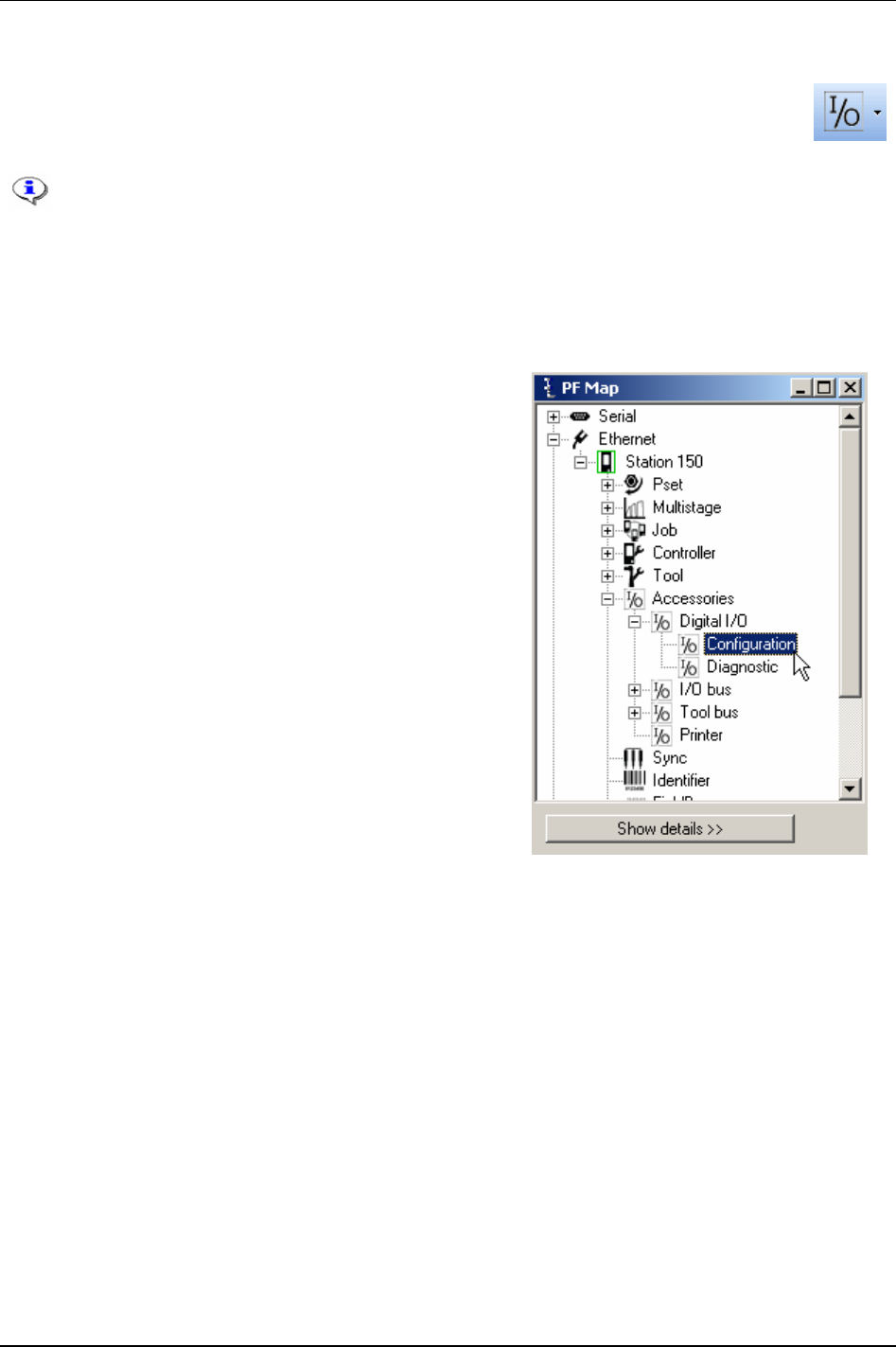
Accessories
10 Accessories
In the Accessories branch the digital inputs and outputs of the PF are configured and
diagnosed. The branch also includes information about the devices connected to the I/O bus
and tool bus, and how to configure these devices.
This section includes screenshots from ToolsTalk PF. The screenshots shows examples of
parameter settings and is NOT intended to be generally applicable. Check with your
local Atlas Copco reprehensive how to set up your specific system environment.
See chapter
Parameter list for a description of all available Accessories options.
10.1 Digital I/O
In the PF Map, select Accessories - Digital I/O and double-
click
Configuration.
The
I/O set window appears.
Power Focus has extensive I/O capabilities. Apart from the internal I/O ports it is also possible to
connect up to 15 external I/O-devices to the Power Focus I/O bus, such as a Pset selector, RE-Alarm, I/O
Expander, StackLight, Operator Panel and Tracker Arm.
Select
Device type.
Select
Digital inputs and Relays (with relay timer). For more information, see section Digital inputs and
outputs.
9836 3123 01 109 (330)
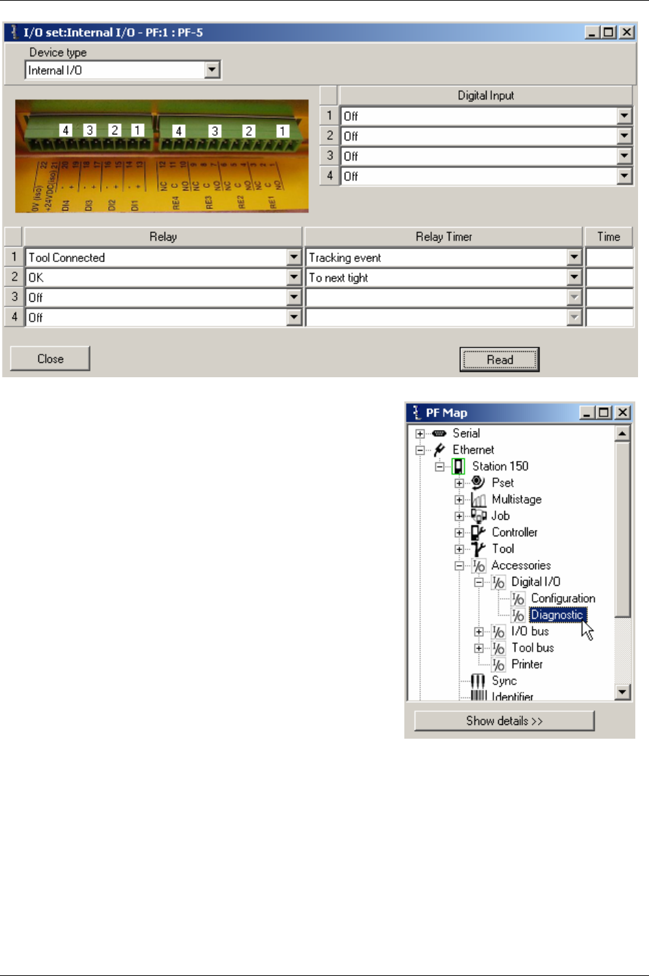
Accessories
In the PF Map, select Accessories - Digital I/O and double-click
Diagnostic.
110 (330) 9836 3123 01
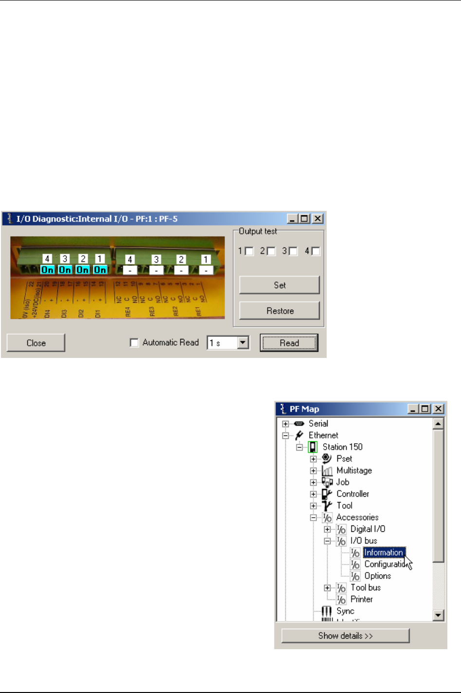
Accessories
The I/O Diagnostic window appears.
Here the status of all internal and external I/O-devices can be viewed.
It is possible to
Set the status of relays. All configured I/O-devices will appear on the list of available
devices. This function tests the interaction between the PF and different external devices. For instance it
could be useful when trouble shooting complex systems with one or several PLC units connected to the
controller.
The
Read key shows the status of the selected I/O-device. The read status key has to be clicked in order
to update this view to reflect changes.
Output test function enables settings of relays on a selected I/O-device. The new status of the relays is set
when
Set key is clicked.
The
Restore key will restore the relays to reflect the current status of the PF. To update this view to
reflect changes triggered by other events click read status.
10.2 I/O bus
Power Focus has extensive I/O capabilities. Apart from the
internal I/O ports it is also possible to connect up to 15
external I/O devices to the Power Focus I/O bus.
In the PF Map, select Accessories - I/O bus and double-click
Information.
9836 3123 01 111 (330)
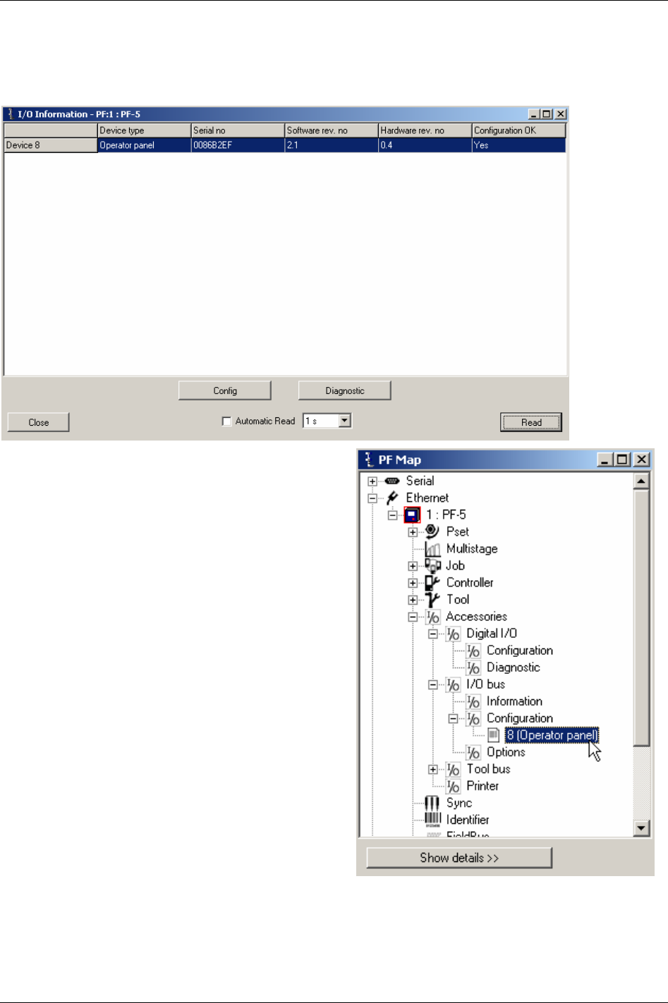
Accessories
Information for each device on the I/O bus is displayed.
Click
Config to configure the selected device.
Click
Diagnostic to diagnose the selected device.
In the PF Map, select
Accessories - I/O bus-
Configuration. Double-click on the device to configure.
112 (330) 9836 3123 01
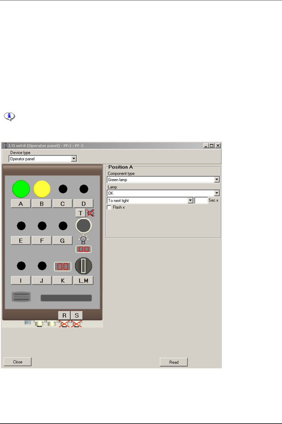
Accessories
Make settings for the device by clicking on the positions.
Following device types are available:
I/O Expander
RE-Alarm
Selector Pset 4-pos
Selector Pset 8-pos
Operator Panel
StackLight
Parameter arm
See the user guides for each accessory device for more information.
Click
Close when finished with configuration.
9836 3123 01 113 (330)
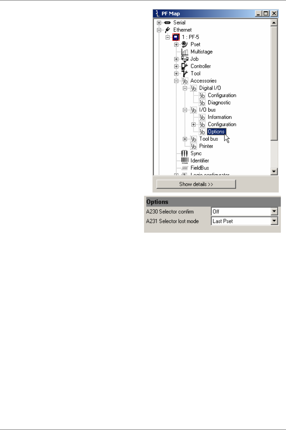
Accessories
In the PF Map, select Accessories - I/O bus and double-
click
Options.
Make settings for
Options.
Close windows when finished.
114 (330) 9836 3123 01
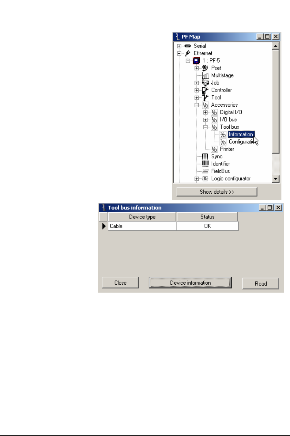
Accessories
10.3 Tool bus
In the PF Map, select Accessories - Tool bus and double-click
Information.
Select Device type and click
Device information.
9836 3123 01 115 (330)
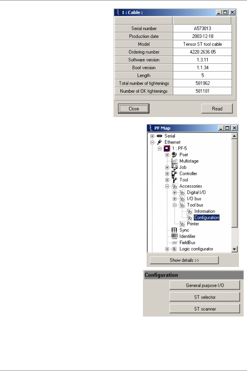
Accessories
The Device information window appears.
Close windows when finished.
In the PF Map, select
Accessories - Tool bus and double-click
Configuration.
In the Tool bus Configuration window, click
General
purpose I/O.
Make settings for the digital inputs and outputs (see chapter
Digital inputs and outputs for descriptions of available
selections).
116 (330) 9836 3123 01
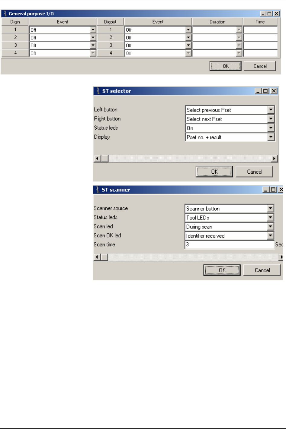
Accessories
In the Tool bus Configuration
window, click
ST selector.
Make special settings for the ST
selector (buttons, status LEDS
and display).
In the Tool bus Configuration
window, click
ST scanner.
Make special settings for the ST
scanner (scanner source, status
LEDs, scan LED, Scan OK LED
and scan time).
Close windows when finished.
9836 3123 01 117 (330)
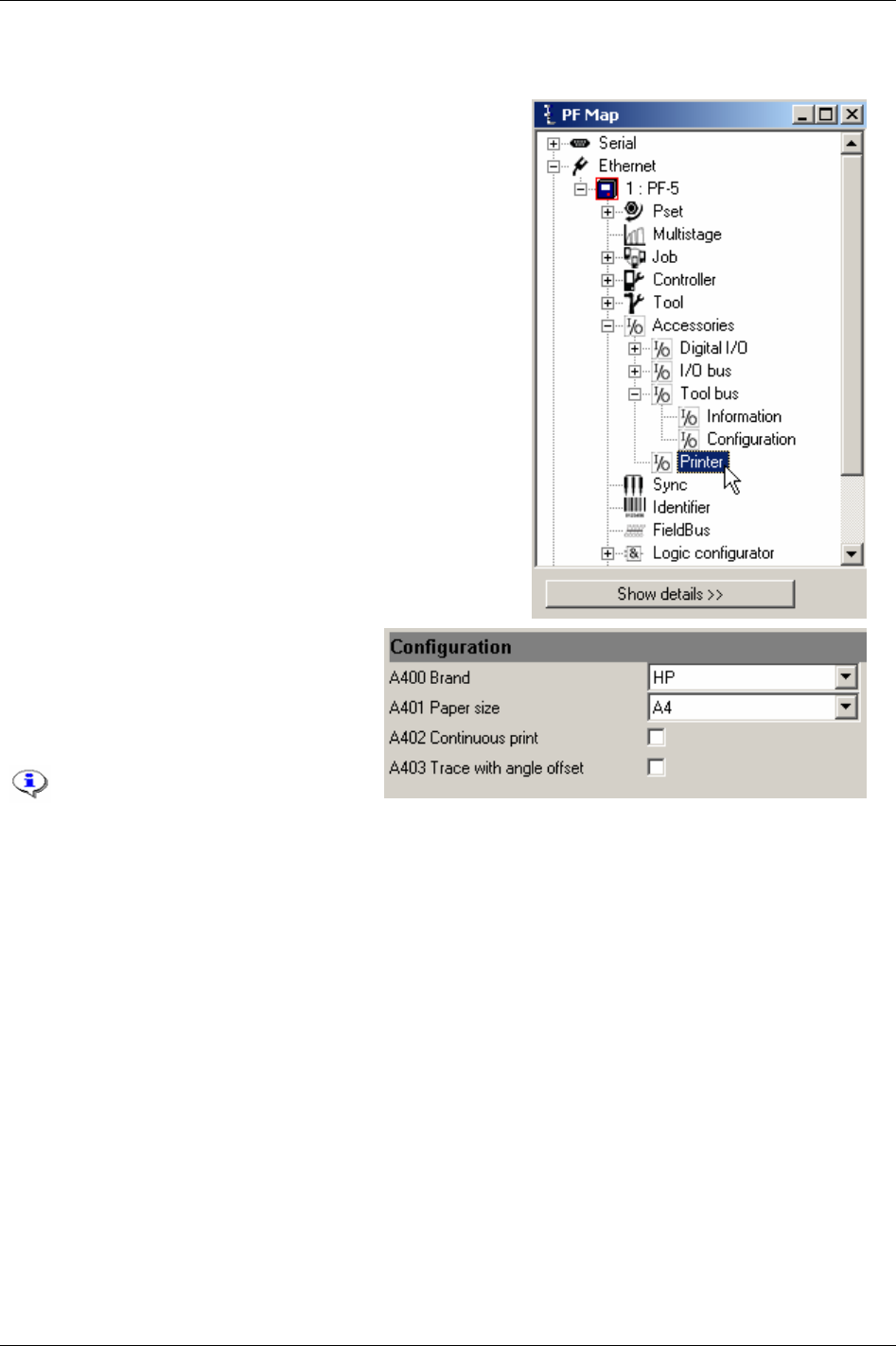
Accessories
10.4 Printer
In the PF Map, select Accessories and double-click Printer.
The connected
Brand [A400] and Paper size
[A401] are setup here. Continuous print [A402]
can be activated. Push the Print button on
the Power Focus Graph front panel to view
a list of available report to print.
Laser printers might not handle
continuous prints, only single
sheet printouts.
Close windows when finished.
118 (330) 9836 3123 01
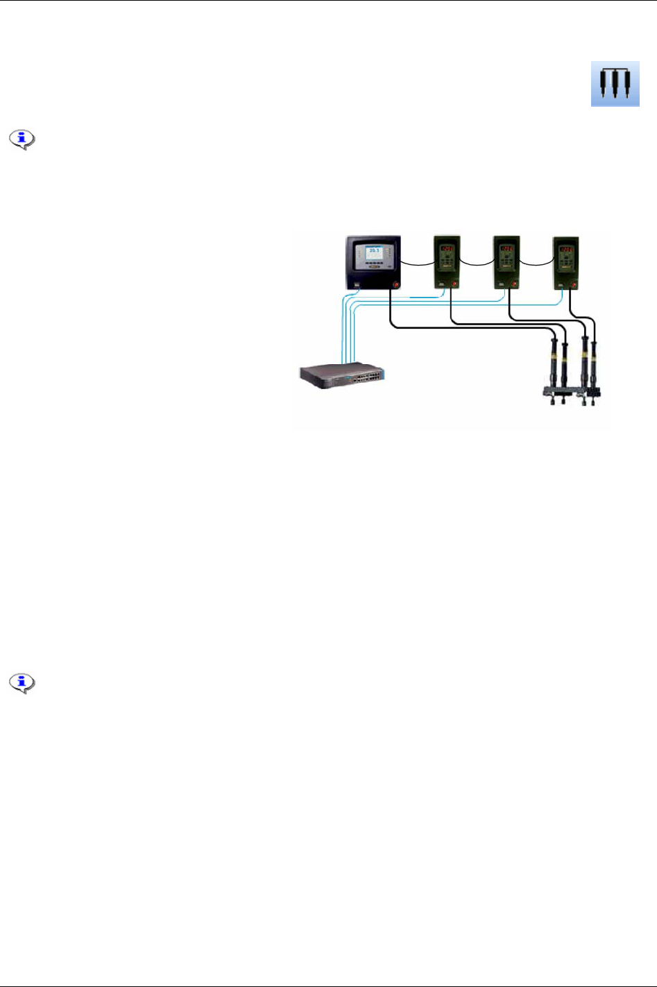
Sync
11 Sync
With the Power Focus RBU gold it is possible to synchronise groups of spindles and tools
performing the same task simultaneously. This function is called
Sync. Examples where Sync
is used are the tightening of car wheel bolts and the tightening of cylinder head bolts.
This section includes screenshots from ToolsTalk PF. The screenshots shows examples of
parameter settings and is NOT intended to be generally applicable. Check with your
local Atlas Copco reprehensive how to set up your specific system environment.
See chapter
Parameter list for a description of all available Sync options.
A
Sync group (see figure to the right) consists
of two to ten PF units, working in the same
Cell (a Cell can consist of more than one
Sync group). One of the controllers is defined
as
Sync reference. The other controllers are
Sync members. The Sync reference remotes
the Sync members (i.e. the Sync reference
decides and controls which Psets/Multistages
to run).
A requirement for using the Sync function is
to first create a Cell, see chapter
Controller.
For a description of how to do Sync motor
tuning, see chapter
Tool.
Sync is performed in steps where all synchronised spindles wait for each other at a number of
“checkpoints” before they continue with the next step. A normal two stage tightening has checkpoints at
First target [P111] and Final target [P113].
Time critical synchronisation communication is performed over the Power Focus internal I/O bus,
which means that all controllers have to be connected via the I/O bus. Ethernet communication is used
for non-time critical communication such as start-up time, creating/updating Psets and Multistages and
transferring result data between the Sync reference and the Sync members. The Sync function can also
perform Multistage tightenings to create a synchronised tightening sequence consisting of several steps.
A Sync group can be part of a Job (see chapter
Job).
It is the Job reference, and not the Sync reference, that counts the batch in a Job with
Sync.
9836 3123 01 119 (330)
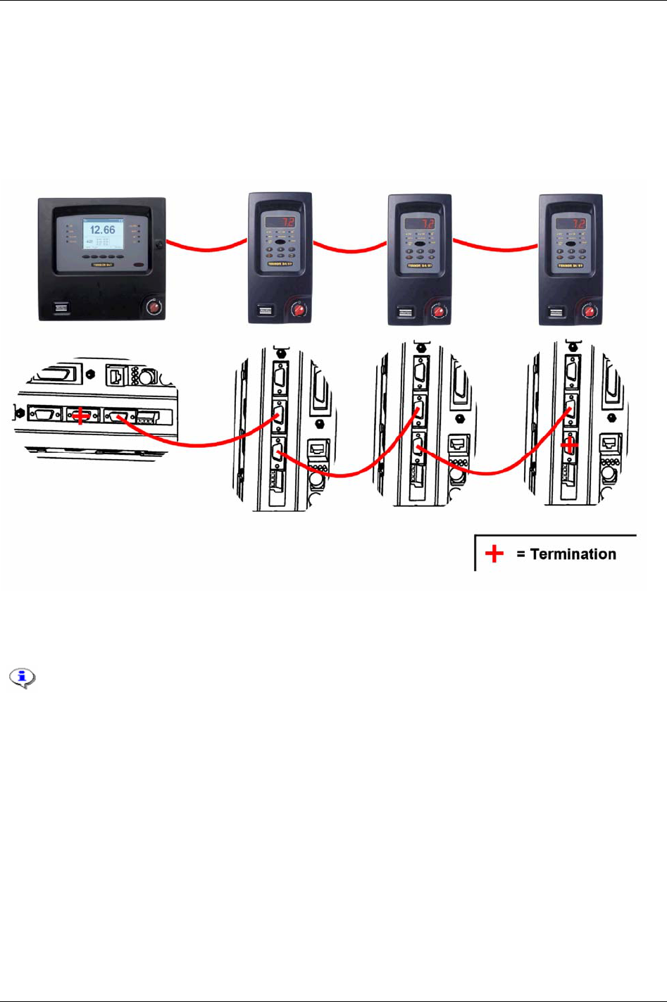
Sync
11.1 Hardware configuration
Connect all Sync members and the Sync reference via the I/O bus. The I/O bus connectors are located on
the back panel of the PF.
In the figure below is four PF units connected via the I/O bus. It is necessary to connect the I/O bus
connections on the controllers with connectors in the way the lower part of the figure shows.
The 4-pin remote start connector must be configured for remote start, see chapter
Connecting devices. This
should be done on each controller in the Sync group, and according to the selected start signal input on
the Sync reference. If an external start switch is used, connect it to the Sync reference only.
Do not connect two Sync groups via the I/O bus.
Do not configure any external I/O-devices (device 1-15) on the Sync members.
120 (330) 9836 3123 01
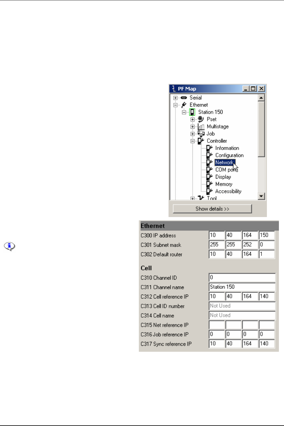
Sync
11.2 Sync members configuration
To check before configuration:
Make sure that all PF units in the synchronised group are connected through the internal I/O bus and
that a correct connection is made.
Make sure that all PF units in the synchronised group are part of the same Cell (see chapter
Controller).
Decide which controllers should act as Sync reference and Sync members.
In the PF Map, expand the
Controller branch and double-click
Ethernet.
Set an IP address to the controller with parameter
Sync reference IP [C317].
All Sync members in a Sync group
must have the same Sync reference IP
address.
To be able to use Sync start, the 4-pin
remote start connector on the Power
Focus back panel must be configured
for remote start. See chapter
Connecting devices.
9836 3123 01 121 (330)
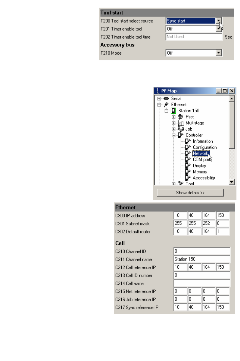
Sync
Select Tool - Configuration - Tool start.
Set
Tool start select source [T200] to Sync
start.
Click
Store to save settings.
Restart the Sync member controller.
Repeat the procedure for all Sync
members.
11.3 Sync reference configuration
In the PF Map, expand the Controller branch and double-click
Ethernet.
Set Sync reference IP [C317] equal to IP address
[C300]
.
Click
Store to save settings.
Restart the Sync reference controller.
After the restart, connect ToolsTalk PF to the
controller again.
122 (330) 9836 3123 01
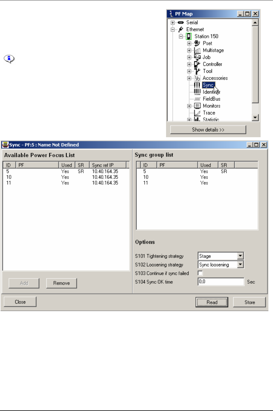
Sync
In the PF Map, double-click Sync.
Select controllers in the
Available Power Focus list.
Click
Add to create a Sync group list.
Make wanted selections in the
Options field.
Option “SynchroTork” for parameter
Tightening
strategy [S101]
is only available for PF 4000.
SynchroTork is not applicable for angle and DS
control strategies.
9836 3123 01 123 (330)

Sync
11.4 Running a Sync group
When the Sync group is running, the Sync reference alone is used for programming and selecting Pset
etc. I/O bus units, such as RE-Alarm, Socket Selector and I/O Expander, can only be controlled from the
Sync reference. On the Sync members only the internal I/O can be used.
In a synchronised application the Sync communication has top priority on the I/O bus
when the tools are running. For that reason tool start, tool disable and other safety critical
functions must not be connected to the I/O bus via I/O Expander.
The status information on each controller and tool is the individual result for that spindle. The overall
Sync OK/NOK can be given on the Field bus, RE-Alarm or relays controlled by the Sync reference. The
results from every spindle are registered separately. The status from individual Sync members can be
viewed on the Sync reference controller.
11.5 Troubleshooting
Symptom Reason/Action
Tools in a Sync group do not
start
There are a variety of possible reasons for this behaviour.
Programming-related errors:
Sync member has not set
Tool start select source [T200] to “Sync start”.
Wrong
Sync reference IP [C317] in the Sync member.
No reboot after programming
Hardware-related errors:
IP connection between one of the Sync members and the Sync reference is lost.
I/O bus cable not correctly connected or broken.
Missing I/O bus connection.
The remote start input in Sync members not correctly wired.
Error elimination:
Select a new Pset from the Sync reference. If all Sync members change to the same Pset, the
Sync group programming is correct. If not, check the programming and the Ethernet cables and
connections.
Select normal loosening and start a loosening from the Sync reference. If not all Sync members
start, check the tool trigger configuration in Sync members and the wiring of the remote start
input. Check also the I/O bus connection and the I/O bus cabling.
If a single spindle does not start, the tool, tool-cable or controller might be broken.
If all spindles in the group start loosening but not tightening check that all Psets are configured
in the same way. If not restore them again from the Sync reference (all Psets must be configured
from the Sync reference).
E870 (Sync reference), E871
or E872 is displayed.
See chapter Event codes.
124 (330) 9836 3123 01

Identifier
12 Identifier
The Identifier section describes the single and multiple identifier functions with features.
Identifiers can be sent to the Power Focus via a scanner (connected to the serial port), Field
bus, Ethernet or a ST scanner (connected to the ST tool).
Power Focus accepts incoming identifiers with up to hundred characters, of which fifty can be declared
as a
Significant string. A significant string is an identifier filter for Power Focus acceptance.
Identifiers sent to Power Focus are not allowed to contain the characters apostrophe (’)
and colon (:).
This section includes screenshots from ToolsTalk PF. The screenshots shows examples of
parameter settings and is NOT intended to be generally applicable. Check with your local
Atlas Copco reprehensive how to set up your specific system environment.
See chapter
Parameter list for a description of all available Identifier options.
One identifier can be defined with up to fifty (of hundred) significant positions
The following conditions must be met for Power Focus to accept an incoming identifier:
Incoming identifier string
must be initiated with “STX” and terminated with “EXT” (barcode reader
standard).
Input source must be correct (accepted).
Length (if specified or maximum hundred characters long) must be correct.
Incoming identifier must match the defined significant string.
If
1. restoring of identifier configuration is made
2. or a
Reset all identifier is made (command in identifier monitor or digital input)
3. or the parameters
Reset all identifier at Job done [J342] and Reset all identifiers at Pset batch done [I183] are
activated
Then the following will happen:
All identifiers will be reset.
Work order will be (cleared) aborted.
Tool will be unlocked if
Tool locked during work order [I181] is activated.
An incoming identifier that goes directly to a Job or Sync client will erase the received
identifier that is sent to the client from the Job or Sync reference.
If the system is set up in a Cell Job or Sync configuration, the parameter
No. of identifier
result parts [C604]
must be configured with identical values (1-4) for all PF units included in
the Job/Sync group.
9836 3123 01 125 (330)

Identifier
12.1 Single Identifier
With the Single identifier solution Power Focus can receive one type of identifier called Type 1. This type
can be defined with up to 400 significant strings and provide Pset/Multistage and Job selections from a
PF.
It is possible to store up to 25 identifier characters in Result part 1 (old VIN no.). Result part 1 is part of
the tightening result in the Power Focus database.
12.2 Multiple Identifier
With Multiple identifier solution Power Focus can receive up to four different types of identifier strings,
the single identifier
Type 1 (see single identifier above) plus three more types (Type 2, Type 3 and
Type 4). Types 2-4 only contain one significant string each. It is not possible to specify type 2-4 for
Pset/Multistage/Job selection (as for type 1).
Multiple identifiers provide storage in four result parts (
Result part 1, Result part 2, Result part 3 and
Result part 4). The result parts are stored together with each tightening result in the Power Focus.
The multiple identifier solution requires RBU gold or silver.
When using more than one result part, which is the default configuration in Power Focus,
it is necessary to increase the parameter
No. of identifier result parts [C604]. For more
information, see section
Result parts.
12.2.1 Work order
A Work order consists of different types (types 1-4) of identifiers. It is useful when Power Focus should
receive identifiers in a predefined order.
An identifier type can be included or not included in the work order, but during the sequence Power
Focus only accepts the types included. Type 1 must be part of the work order (i.e. it is not possible to run
a work order without type 1).
A work order has to be completed before Power Focus selects the Pset/Multistage/Job. In case a work
order exists and type 1 is configured to select a Pset/Multistage/Job.
The work order also has to be completed before Power Focus stores the accepted identifiers in the
tightening result database (identifier types not included in the work order can be stored in the tightening
results immediately after they are accepted).
All types outside the work order must be uniquely defined. Uniquely defined means a
separate input source, length or significant string compared to types included in the word
order.
When
Tool locked during work order [I181] is activated, the tool will be locked when the first identifier type
in the work order is accepted. When the work order is completed the tool is unlocked.
The tool will immediately be unlocked during a work order when;
Restoring of identifier configuration is done.
Reset all identifiers command is performed via digital input, open protocol or identifier monitor.
Reset latest identifier command is performed after the first type in the work order is accepted.
126 (330) 9836 3123 01
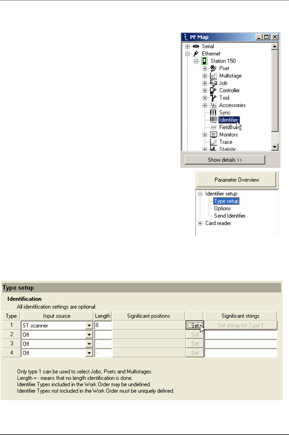
Identifier
12.3 Identifier types and work order
As described above there are different types of identifiers.
Furthermore, it is possible to create a work order with a number
of identifiers. This section includes a step-by step guide how to
set up a work order.
In the PF Map, double-click
Identifier.
In the Identifier window, select
Type setup under Identifier setup.
To create an identifier type, select
Input source.
State
Length of the incoming identifier (length “- “ means no length check).
Click
Set to mark significant positions.
9836 3123 01 127 (330)

Identifier
In the pop up window Identifier significant position setup, mark significant positions for the identifier.
The characters must not necessarily be selected in one row.
Click
OK.
Click Set strings for Type 1.
128 (330) 9836 3123 01
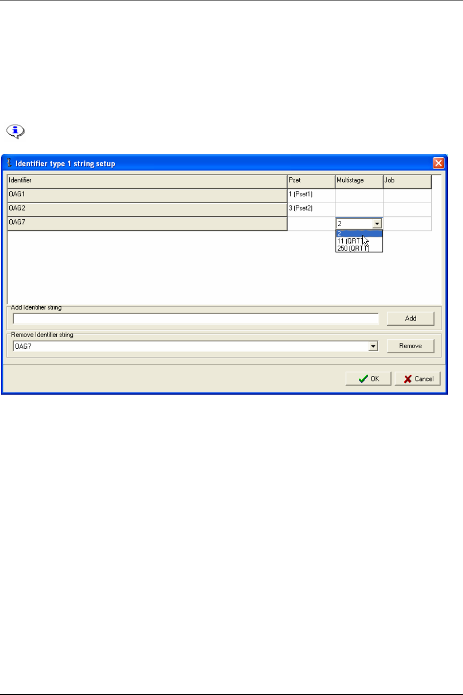
Identifier
Write significant characters in the field for Identifier string.
Write string name in field
Add identifier string and click Add.
Select
Pset, Multistage or Job for the identifier string.
When finished, click
OK.
Continue to add new identifier strings or go back to the type setup menu and click
Store.
It is not allowed to add a string more than once, but it is allowed to connect a specific Pset,
Multistage or Job ID to more than one string.
9836 3123 01 129 (330)
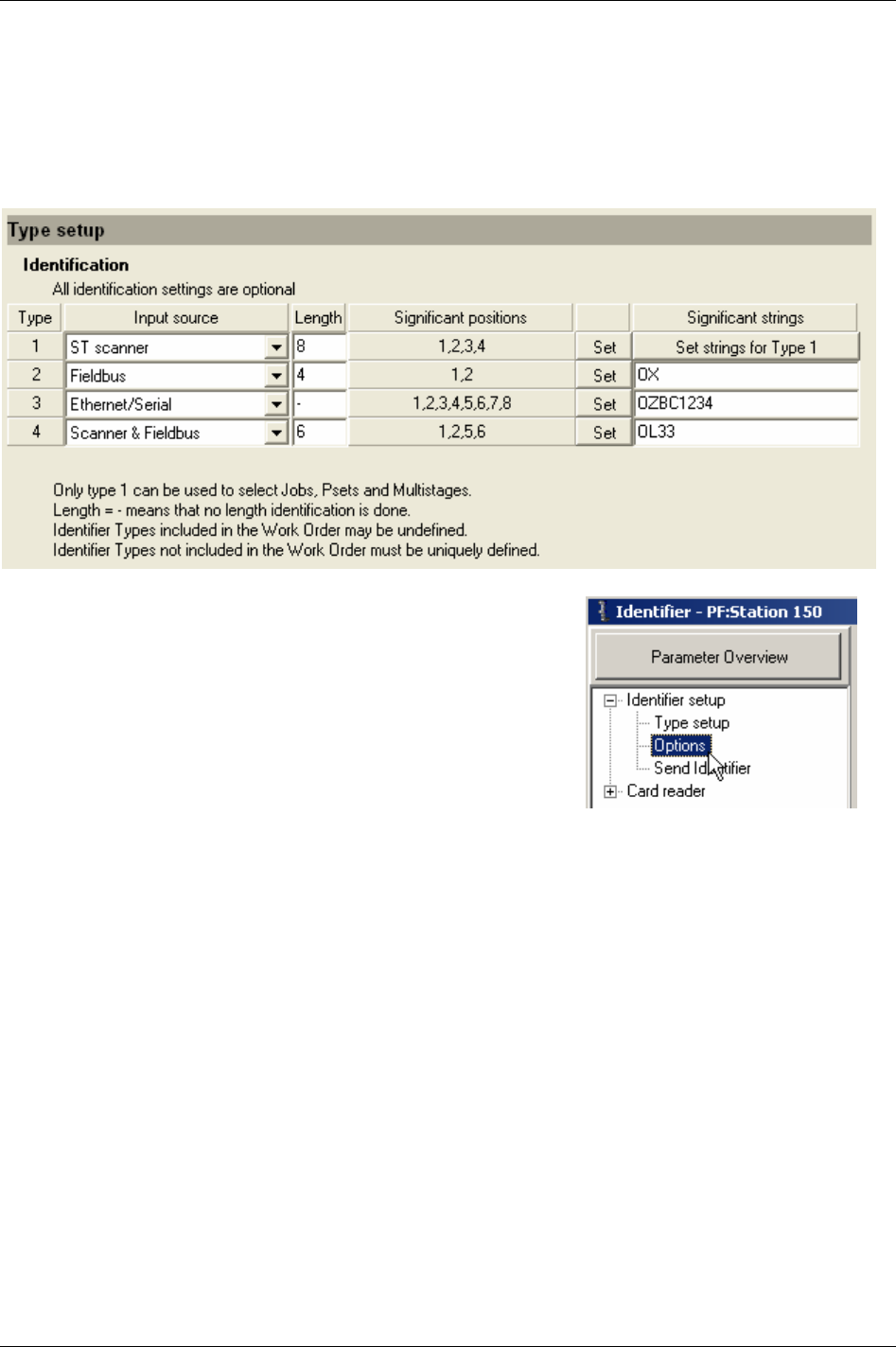
Identifier
In the Type setup menu it is now possible to type identification settings for type 2, 3 and 4. Select Input
source and Length, set Significant positions and write Significant strings for the specified type.
Types 2 to 4 in the example below contain only one significant string each, and are not connectable to
Psets, Multistages or Jobs (like type 1).
Click
Store to save settings.
Select
Options in the Identifier setup branch.
130 (330) 9836 3123 01
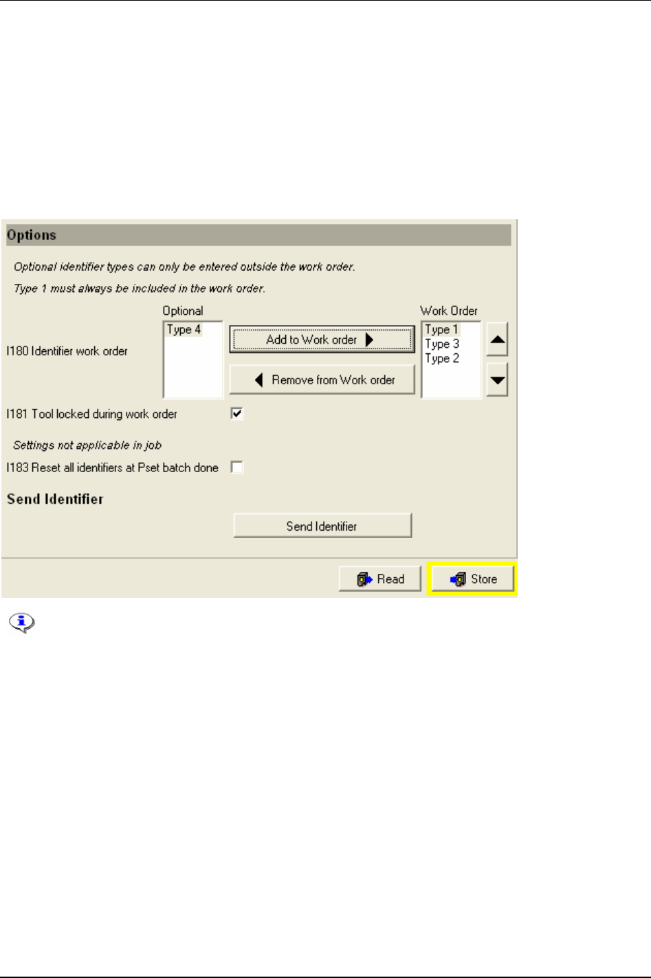
Identifier
Define a Work order. See section Work order for more information.
It is possible to have
Tool locked during work order [I181].
When activating
Reset all identifiers at Pset batch done [I183]:
All identifiers will be reset.
Work order will be (cleared) aborted.
Tool will be unlocked if
Tool locked during work order [I181] is activated.
Send identifier gives the possibility to manually send an identifier string from ToolsTalk PF to the PF.
To select Pset/Multistage or Job from an identifier string, parameters
Pset select source
[C200], Job select source [C201] or Job select source override [C202] have to be set to
“Identifier”.
9836 3123 01 131 (330)
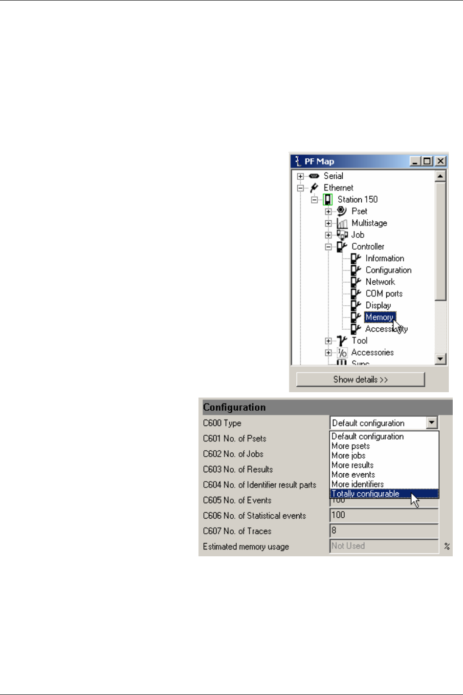
Identifier
12.3.1 Result parts
In ToolsTalk PF (presuppose having a RBU gold) it is possible to display and store up to four result parts,
each max 25 characters long, which will be stored in the Power Focus database together with every
tightening result.
When using more than one result part (only for multiple identifier users) it could be necessary to increase
the number of identifier result parts in the Power Focus memory. This section describes how to do this.
The default setting is one result part (old VIN). The Power Focus configurable memory can be changed
to handle up to four result parts and is described below.
In the PF Map, expand the
Controller branch and double-click
Memory.
In the list for
Type [C600], select Totally
configurable
.
132 (330) 9836 3123 01
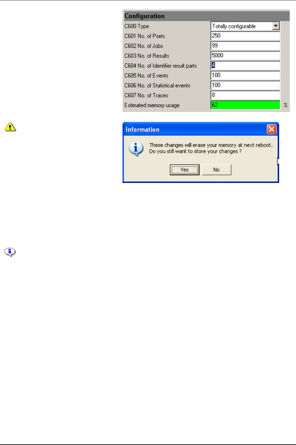
Identifier
Increase No. of identifier result parts [C604] to
be used, from 1 to 2, 3 or 4.
Estimated memory usage cannot exceed a
hundred percent. It is therefore
recommended to decrease
No. of results
[C603]
in order to increase No. of identifier
result parts [C604]
.
Click
Store to save settings.
The changes made in
configurable memory setup will
reset the Power Focus memory
at the next reboot. All data
(tightenings results,
programmed Psets, Jobs, Sync
groups etc.) will be lost.
The only exception is
parameters
IP address [C300],
Subnet mask [C301] and Default
router [C302]
which will remain
after the reboot.
Click
Yes to continue.
Click
No to cancel.
When changing the memory setup the PF must be rebooted for changes to take effect. Note
that it is necessary to “Read PF from file” two times and reboot the PF one extra time. See
chapter
Controller for instructions.
It is recommended to reboot immediately.
Configurable memory is only available for RBU gold and silver.
9836 3123 01 133 (330)
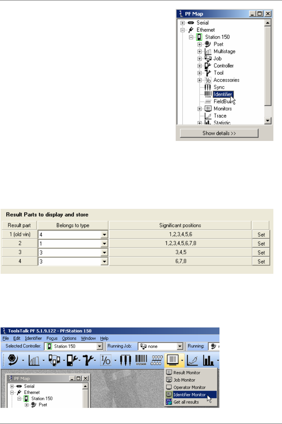
Identifier
After reboot, double-click Identifier in the PF Map.
The Result parts are displayed under section
Result parts to display and store in the Type setup window.
Select
Identifier types (type 1-4) that the result parts should belong to.
Set
Significant positions by marking character positions that should be added to the result parts.
In the screen shot example below, six positions from type 4 will be copied to result part 1 and stored
together with the tightening result. Eight positions for type 1 will be copied to result part 2, and so on.
Click
Store when finished.
12.3.2 Identifier monitor
Identifier monitor displays the status (accepted/not accepted) of the identifier included in the Work order
and
Optional identifier (not included in work order).
In ToolsTalk PF, click on the arrow to the right of the monitor icon and select
Identifier monitor.
134 (330) 9836 3123 01
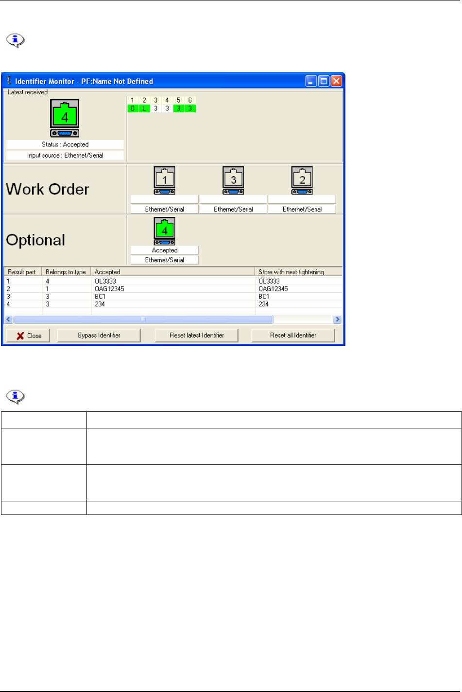
Identifier
In the figure example below, all Identifier input sources are set to “Ethernet/serial”.
12.3.3 Functions in identifier monitor
These functions are only available from ToolsTalk PF.
Function Description
Bypass identifier Skips a specified identifier type in a work order.
It is not possible to bypass the first type in the work order if it simultaneously exist types outside the
work order.
Reset latest identifier The latest accepted identifier string is cleared with the command (or digital input) “Reset latest
identifier”.
It is not possible to perform “reset latest identifier” for the last type in a work order.
Reset all identifier All accepted identifier strings are cleared with the command (or digital input) “reset all identifiers”.
9836 3123 01 135 (330)
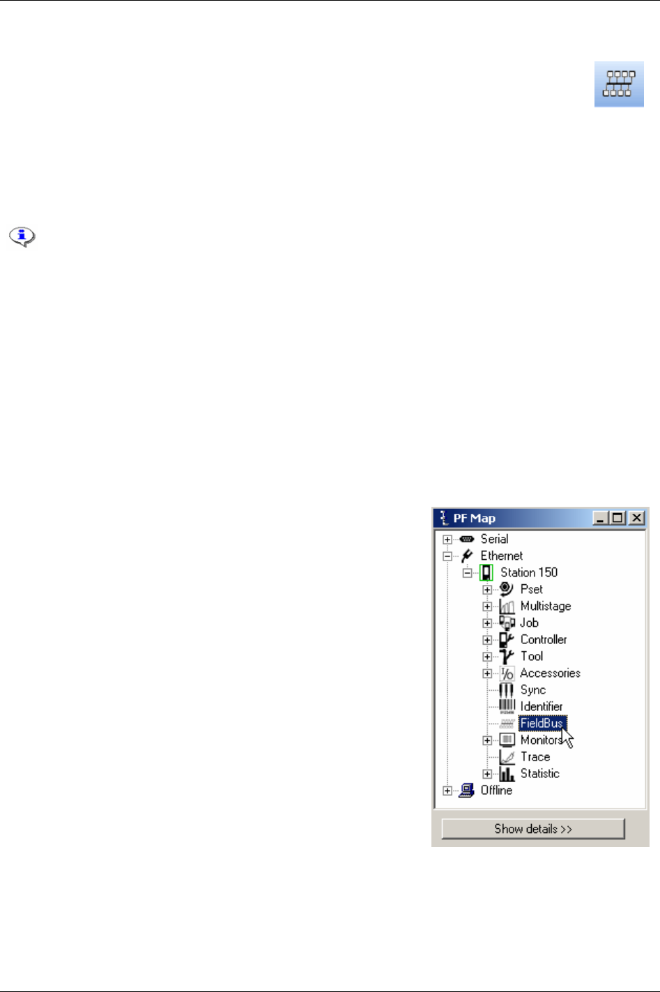
Field bus
13 Field bus
A Field bus communication can be used for data communication between Power Focus and
PLC’s (programmable logic controllers). It is an effective and fast way for the data transfer of
short data packages. Field bus is normally used to send discrete I/O data instead of using a
large number of cables that have to be hard wired to relays and digital inputs.
There are many different Field bus standards on the market and they all have different hardware and
software protocols. To be able to communicate on Field bus, the Power Focus must be equipped with a
specific card for the preferred type of Field bus.
ProfiBus-DP, DeviceNet, InterBus/InterBus2MB,
ModBusPlus, ControlNet, ModBus/TCP, Ethernet/IP, ProfiBus-IO and FL-Net are the possible selections.
Power Focus acts as a client in a Field bus system. A PLC or similar will act as the
reference (master).
This section includes screenshots from ToolsTalk PF. The screenshots shows examples of
parameter settings and is NOT intended to be generally applicable. Check with your local
Atlas Copco reprehensive how to set up your specific system environment.
See chapter
Parameter list for a description of all available Field bus options.
With ToolsTalk PF the Field bus functionality in the PF can be configured to fit the customer specific
bitmap. It is a very easy way to configure or modify a customer specific bitmap. When the configuration
is done it can be downloaded to Power Focus or saved as a file for later use.
See section
Field bus configuration appendix for specific Field bus type data.
13.1 General setup
In the PF Map, double-click Field bus.
9836 3123 01 137 (330)

Field bus
Select Field bus type [F100]
from the drop down menu.
All Field bus parameters
will be reset to default and
data items cleared.
Confirm by clicking OK.
The screenshot below displays available parameters for Field bus type DeviceNet.
138 (330) 9836 3123 01

Field bus
9836 3123 01 139 (330)
Parameters in General setup
The table below shows parameters available for all Field bus types.
Parameter Device-
Net
ProfiBus
-DP
Inter-
Bus
ModBus
Plus
Control-
Net
ModBus/
TCP
Ethernet
/IP
Inter-
Bus
2MB
Profinet
-IO
FL-
Net
Field bus type X X X X X X X X X X
To PF data
length
X X X X X X X X X X
From PF data
length
X X X X X X X X X X
FB update
interval
X X X X X X X X X X
Tool stop at
offline
X X X X X X X X X X
Set node
address and
baudrate from
X X X X X X X
FB node
address
X X X X
Baudrate X
Set source
address from
X
Source address X
Connection
mode
X
PCP length X X
Process data
length
X X
From PF global
data length
X
To PF global
data length
X
Bitmap select X X X X X X X X X X
IP address X X X X
Subnet Mask X X X
Gateway X X X
Device Name X
From PF Data
Offset
X
To PF Data
Offset
X
Virtual Field
bus
X
Virtual from
PF data length
X
Virtual to PF
data length
X
Virtual from
PF data offset
X
Virtual to PF
data offset
X
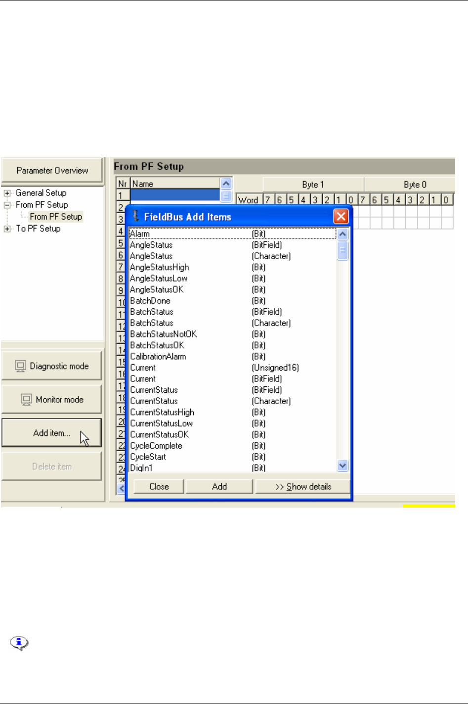
Field bus
13.2 From PF setup and to PF setup
Select From PF setup or To PF setup.
Via
From PF Setup the bitmap that is sent out from the Power Focus can be configured.
Via
To PF setup the bitmap that is sent in to the Power Focus can be configured.
Click
Add item… to activate a selection list. On the right side of the item list, see information about
highlighted item.
Highlight the item and
double-click on it or click Add. The item will then be entered to the item list on
the first available line.
In the list start word, start byte and start bit for the selected item are visible. The start word, byte and bit
give the start position of an item in the bitmap. The length can also be seen and sometimes changed. If
this does not match the wanted bitmap it is easy to change the length and position in the bitmap by
changing the start positions in the item list.
Change one line at a time and then click
Enter after each line is changed. It is also possible to drag and
drop directly in the bitmap. In this case, the start positions in the item list are updated automatically. If
the bitmap is changed, and a conflict occurs, this part is marked with red.
To delete an item, highlight it in the item list and click Delete item.
The max number of selected items is 60 in From PF setup and 60 in to PF setup.
For detailed information for the possible selections, see section
Field bus configuration appendix.
140 (330) 9836 3123 01
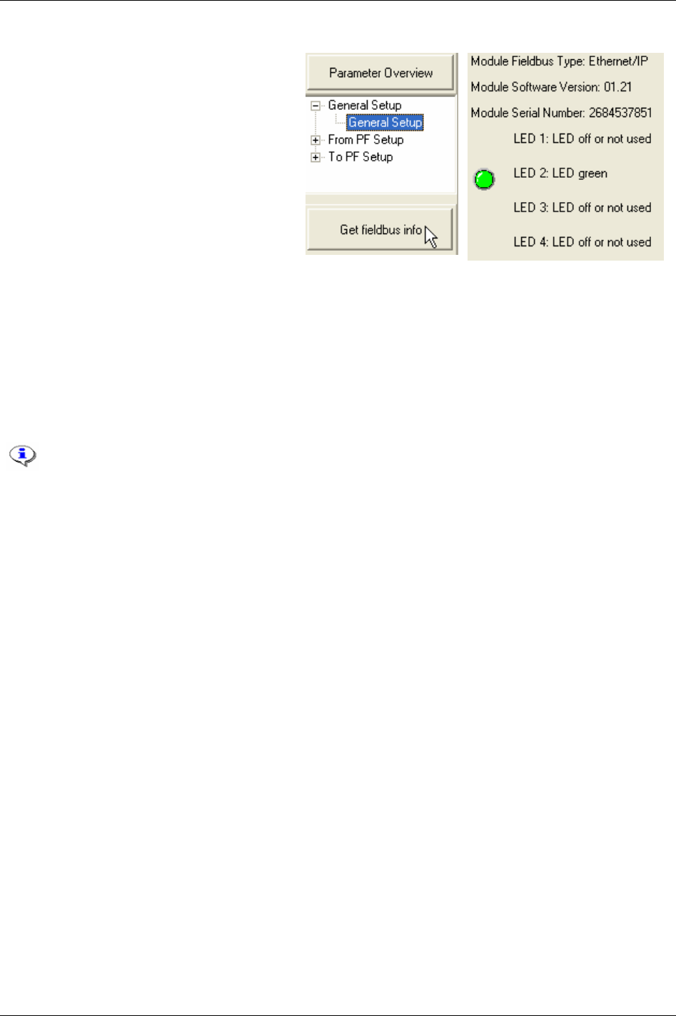
Field bus
13.2.1 View Field bus information
Select General setup.
Click
Get Field bus info to display Field bus
module type, module software version,
module serial number and status of the LED’s.
13.2.2 Field bus modes
Diagnostic mode
When Diagnostic mode is on, it is possible to set Field bus data in ToolsTalk PF and send the data to PF
by clicking Set value. If Diagnostic mode “From PF” is used the Power Focus passes data from
ToolsTalk PF to PLC and ignores the data from Power Focus. If Diagnostic mode “To PF” is used the
Power Focus activates functions, which is set in ToolsTalk PF and ignores PLC data.
In Diagnostic mode the operator can only change a small part of the Field bus setting data
(only the content of a bit from zero <--> one). Rest of the settings can only be done in
Normal mode.
Monitor mode
Monitor mode is used to monitor Field bus data communication for testing purpose. This function works
only when ToolsTalk PF is online (connected to the PF).
When Monitor mode is active, the data from Power Focus to PLC is visible in the
From PF window
bitmap. Likewise the data from PLC to Power Focus is visible in the
To PF window bitmap. It is not
possible to change and store Field bus configurations in monitor mode. Data can be displayed in two
formats, defined data type format and binary format. The data in the monitor windows is updated at a
rate of three messages per second.
Normal mode
The third mode is called Normal mode. Normal mode is when none of the Diagnostic mode or Monitor
mode is selected. Under this mode, the operator can change position of a bit in a word (in a byte) for a
selected item (not the content of the bit). For instance, the operator can change job off bit position 7 to
bit position 3 by drag and drop it or just by writing it into the Bit column and press enter.
13.2.3 Store to file and read from file
Store and read Field bus configurations to file. Use the read/save Field bus functions in the file menu in
ToolsTalk PF. To store to or read from a file first activate the Field bus window. The Field bus file
extension is “*.pff”.
9836 3123 01 141 (330)

Field bus
13.3 Field bus selector
To use this function the parameter
Pset select source [C200] must be set to “Field bus
selector”.
The Field bus selector function makes it possible to control the selection of Psets on selectors from an
external source via the Field bus. The intended type of working stations where the proposed software is
to be installed are rework stations and similar. Such stations don’t have fixed work flows for the
tightening controllers, but are often unique for each work piece depending on the failed tightenings that
have been performed previously on that work piece. The external source (e.g. a PLC) is responsible for
setting the green LED’s on the selector(s) and for selecting the Psets in the Power Focus.
For Pset selector I/O setup instructions, see chapter
Controller. For Field bus configuration, see section
Field bus configuration appendix.
13.4 Disable Field bus carried signals
A lot of users run PLC selected Jobs over the Field bus in automatic mode (i.e. “Field bus” is selected
for parameter
Job select source [C201]), and select Jobs with a digital input in emergency mode (i.e.
“DigIn” is selected for parameter
Job select source override [C203]). When emergency mode is activated
the Field bus signals could still disturb the communication. To avoid this type of problem it is
recommended to use digital input
Disable Field bus carried signals. When this digital input goes high the
following events occur:
Field bus communication is disabled.
Relay “Field bus carried signals disabled” goes high.
In ToolsTalk PF monitoring mode on Field bus “To PF” side, it is possible to display changes in
signals sent to the PF over the Field bus. (Note that the signals have no effect on the Power Focus,
since all Field bus communication is disabled).
On the Field bus side “from PF”, bits are reset to zero (0).
The traffic of “keep alive” signals continues on the Field bus. In this way no event codes (i.e. “no
connection on Field bus”) will be displayed.
All tools are enabled (presupposed that the tools were disabled from a source over the Field bus
before then).
If there is a running Job, which has been selected via the Field bus, the Job will be aborted.
142 (330) 9836 3123 01

Field bus
9836 3123 01 143 (330)
13.5 Field bus configuration appendix
This appendix describes the different possible selections for the Field bus. It also describes the different
data types that are used in the Field bus configuration.
13.5.1 Bitmap select (Endian mode)
Motorola Endian
Byte 0 Byte 1
7 6 5 4 3 2 1 0 7 6 5 4 3 2 1 0
Intel Endian
Byte 1 Byte 0
7 6 5 4 3 2 1 0 7 6 5 4 3 2 1 0
Motorola Endian is default setting for ProfiBus-DP, InterBus, ModBusPlus and ModBus TCP.
Intel Endian is default setting for DeviceNet, ControlNet and EtherNet/IP.
13.5.2 Field bus data types
The Power Focus uses position format in all encoding and decoding data types. In PF position format the
most significant bit (MSB) is the bit furthest to the left and the least significant bit (LSB) is the bit furthest
to the right.
If a data type is less than one word, the MSB is the bit furthest to the left. If data type is longer than one
word, the MSB is the bit furthest top-left. If a Field bus type uses Intel Endian, byte numbers are swapped
before encoding or decoding to a specific data type.
The data field in the Field bus is from the beginning a blank data field without structure. In order to file
Power Focus item data types into Field bus we define Field bus data type, which holds the information
about placement and structure of a certain application data type mapped into the Field bus data field.
The table below shows the different data types used in Field bus data. The section items from/to PF shows
the data type available for different items.
Data type Description
Bit One bit. Normally used for discrete I/O-data.
BitField (BF) Length is 2 - 8 bits. All bits must be in the same byte. The left bit is the most significant bit and
the right bit is the least significant bit, i.e. 0001=1, 1000= 8.
Character (Char) One byte ASCII code.
CharacterStringChange (CSC) Character string. Each character uses one byte ASCII code. Range: 2 - 25 bytes.
CharacterStringInput (CSI) Character string with an extra “counter” byte in front. The extra byte is an integer counter and
must increase each time when the character string is entered to be able to detect a new input. To
enter the same value again (e.g. the same Job number), just change the counter.
FixedPointNumber (Fixed
point)
Two-byte integer part and two-byte decimal part. The first two bytes hold the integer part and
the last two bytes hold the decimal part. Used to represent torque value.
Unsigned16 (U16) 16-bit unsigned integer. Decimal 0 – 65 535.
Unsigned32 (U32) 32-bit unsigned integer. Decimal 0 – 4 294 967 295.
U32_HNW 32-bit unsigned integer. MSW is the higher number word. Only shown in Intel Endian
CharStringChangeIntel (CSCI) Character string. Each character uses one byte ASCII code. Range: 2 - 25 bytes. This type
makes Intel Endian character string follows byte order; the first character is the lowest byte in
the string. Only shown in Intel Endian
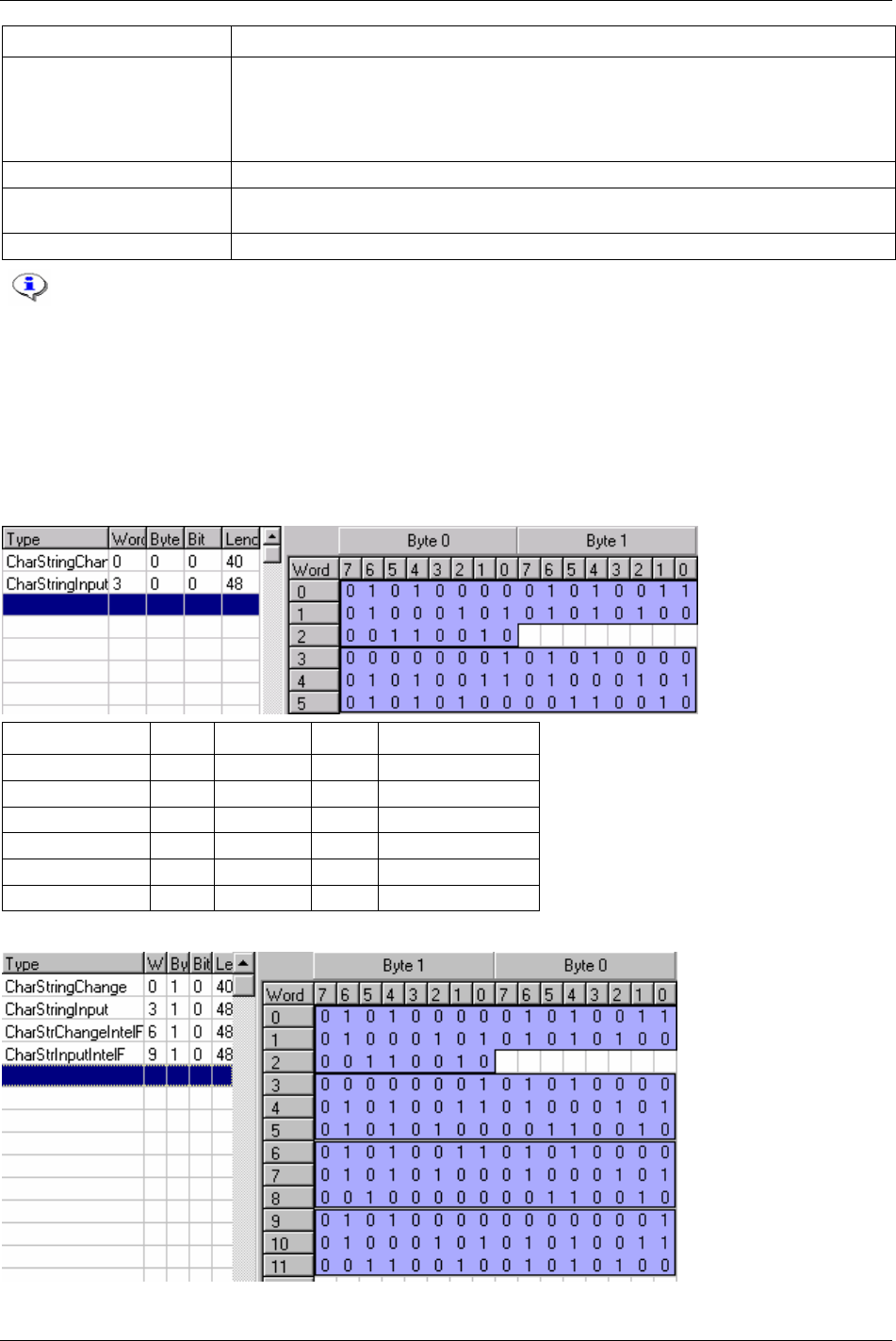
Field bus
Data type Description
CharStringInputIntel (CSII) Character string with an extra “counter” byte in front. The extra byte is an integer counter and
must increase each time when the character string is entered to be able to detect a new input. To
enter the same value again (e.g. the same Job number), just change the counter. This type
makes Intel Endian character string follows the byte order; the integer counter is the lowest
byte in the String. Only shown in Intel Endian
OctetArray (OA) It contains several octet data in the byte order.
LongCharStringChange
(LCSC)
It contains max 100 bytes character.
LongCharStrChIntel (LCSCI) In Intel mode, only allows whole word, up to 100 bytes. Only shown in Intel Endian.
Common for all data types is that a change must occur in PLC output area (To PF) to get
Power Focus to detect a new data entry. For example, if selecting JOB number 3 two times in
a row please select 0 in between.
Character string
Character String is in a reading order, i.e. from left to right, from top to bottom, regardless of the byte
order. The difference between CharStringChange and CharStringInput is a counter byte added before
character string in CharStringInput. A new input is considered when the counter changes.
Motorola Endian
Data type Word Byte 0 Byte 1 Convert to PF data
CharStringChange 0 P S
1 E T
2 2 PSET2
CharStringInput 3 1 (counter) P
4 S E
5 T 2 PSET2
Intel Endian
144 (330) 9836 3123 01
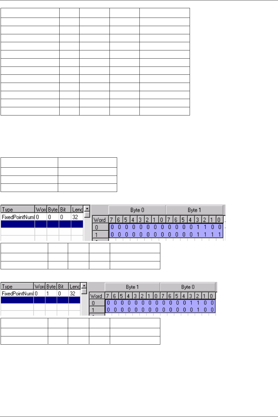
Field bus
Data type Word Byte 1 Byte 0 Convert to PF data
CharStringChange 0 P S
1 E T
2 2 PSET2
CharStringInput 3 1 (counter) P
4 S E
5 T 2 PSET2
CharStringChangeIntelF 6 S P
7 T E
8 2 PSET2
CharStringInputIntelF 9 P 1 (counter)
10 E S
11 2 T PSET2
Fixed point number
Fixed point number integer part is in low number word, and decimal part is in high number word. The
table below shows the conditions valid for the integer and decimal parts (i.e. if integer part is 1 digit or 2
digits, decimal part is 2 digits):
Integer part (in digits) Decimal part (in digits)
1 or 2 2
3 1
4 0
Motorola Endian
Data type Word Byte 0 Byte 1 Convert to PF data
FixedPointNumber 0 0 12
1 0 15 12.15
Intel Endian
Data type Word Byte 1 Byte 0 Convert to PF data
FixedPointNumber 0 0 12
1 0 4 12.04
Integer
Unsigned16 is a 16-bit integer and unsigned32 is a 32-bit integer. U32_HMW is a special case of
unsigned32, which is used in Intel Endian.
9836 3123 01 145 (330)
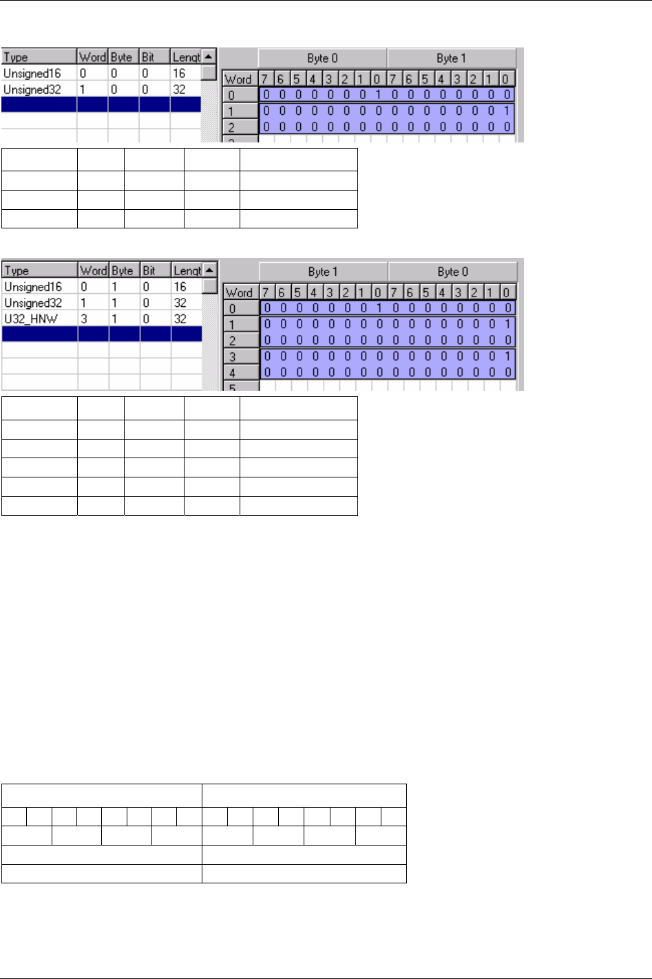
Field bus
Motorola Endian
Data type Word Byte 0 Byte 1 Convert to PF data
Unsigned16 0 1 0 256
Unsigned32 1 0 (MSB) 1
2 0 0 (LSB) 65536
Intel Endian
Data type Word Byte 1 Byte 0 Convert to PF data
Unsigned16 0 1 0 256
Unsigned32 1 0 (MSB) 1
2 0 0 (LSB) 65536
U32_HNW 3 0 1 (LSB)
4 0 (MSB) 0 1
13.5.3 Field bus selector configuration
The Field bus selector function makes it possible to control the selection of Psets on selectors from an
external source via the Field bus. The intended type of working stations where the proposed software is to
be installed is rework stations and similar. Such stations don’t have fixed work flows for the tightening
controllers, but are often unique for each work piece depending on the failing tightenings that have been
performed previously on that work piece. The external source (e.g. a PLC) is responsible for setting the
green LED’s on the selector(s) and for selecting the Psets in the Power Focus.
Set selector LED
In one eight socket selector, the first four positions are for Selector LED 1, and the last four positions are
for
Selector LED 2. If a four socket selector is used, only selector LED 1 is mapped.
Motorola Endian
Byte 0 Byte 1
7 6 5 4 3 2 1 0 7 6 5 4 3 2 1 0
Pos 4 Pos3 Pos2 Pos1 Pos8 Pos7 Pos6 Pos5
Device ID Not used
Selector LED 1 Selector LED 2
146 (330) 9836 3123 01

Field bus
9836 3123 01 147 (330)
Intel Endian
Byte 1 Byte 0
7 6 5 4 3 2 1 0 7 6 5 4 3 2 1 0
Pos 8 Pos7 Pos6 Pos5 Pos4 Pos3 Pos2 Pos1
Not used Device ID
Selector LED 2 Selector LED 1
Selector information
Motorola Endian
Byte 0 Byte 1
7 6 5 4 3 2 1 0 7 6 5 4 3 2 1 0
Pos 4 Pos3 Pos2 Pos1 Pos8 Pos7 Pos6 Pos5
Device ID Socket lifted position number
Selector LED 1 Selector LED 2
Intel Endian
Byte 1 Byte 0
7 6 5 4 3 2 1 0 7 6 5 4 3 2 1 0
Pos 8 Pos7 Pos6 Pos5 Pos4 Pos3 Pos2 Pos1
Socket lifted position number Device ID
Selector LED 2 Selector LED 1
Select Pset and set batch size
In order to set batch size and select Pset from Field bus, parameter Pset select source [C200] must be “Field
bus” or “Field bus selector”. Also, parameter
Batch count [P150] must be set to “Field bus”.
Motorola Endian
Byte 0 Byte 1
Pset ID Batch size
Intel Endian
Byte 1 Byte 0
Pset size Pset ID
Function (Pset select source [C200] is set to “Field bus”)
0 < Batch size < 99 Batch size = 0, Batch size > 99
Pset ID = 0
Select Pset 0 Select Pset 0
0 < Pset ID < 255
Select Pset and set batch size Select Pset 0

Field bus
148 (330) 9836 3123 01
Function (Pset select source [C200] is set to “Field bus selector”)
Selector socket lifted correct Selector socket lifted incorrect
Pset ID = 0 Batch size = any
Select Pset 0 Display event code
Field bus PsetID
mismatch selector lifted socket [E475]
Select Pset 0
0 < Batch size < 99
Select Pset, set batch size and unlock
tool
Display event code
Field bus PsetID
mismatch selector lifted socket [E475]
Select Pset 0
0 < Pset ID < 255
Batch size = 0 or
Batch size > 99
Display event code Field bus PsetID
mismatch selector lifted socket [E475]
Select Pset 0
Display event code
Field bus PsetID
mismatch selector lifted socket [E475]
Select Pset 0
13.5.4 Items from PF
In this section follows a description of the possible items to select when data from the Power Focus is
configured.
Set signal = a signal to set a bit/byte/bytes in the PLC.
Reset signal = a signal to reset a bit/byte/bytes in the PLC.
Items from PF Description Data
type
String
length
Value Set signal Reset signal
Alarm Echo display
alarm LED.
Bit 1 bit 0 = Off
1 = On
Alarm on Alarm off
Char 1 byte
ASCII
O = OK
L = Low
H = High
AngleStatus Status Angle
result.
BF 2 bits 00 = Not used
01 = OK
10 = High
11 = Low
Tightening
result
Start new
tightening or new
Pset selected or
new Job selected
AngleStatusHIGH Angle result is
above max
limit.
Bit 1 bit 0 = Not used
1 = High
Tightening
result
Start new
tightening or new
Pset selected or
new Job selected
AngleStatusLOW Angle result is
below min limit.
Bit 1 bit 0 = Not used
1 = Low
Tightening
result
Start new
tightening or new
Pset selected or
new Job selected
AngleStatusOK Angle result is
within limits.
Bit 1 bit 0 = Not used
1 = OK
Tightening
result
Start new
tightening or new
Pset selected or
new Job selected
BatchDone Indicate batch
finished. Batch
done OK or
NOK.
Bit 1 bit 0 = Not completed
1 = Done
Batch finished Reset result
Char 1 byte
ASCII
O = OK
N = NOK
BatchStatus Batch OK
(done) or NOK
BF 2 bits 00 = Not used
01 = OK
10 = NOK
Tightening
result
Start new
tightening or new
Pset selected or
new Job selected

Field bus
9836 3123 01 149 (330)
Items from PF Description Data
type
String
length
Value Set signal Reset signal
BatchStatusNOK Batch is NOK. Bit 1 bit 0 = Not used
1 = NOK
Tightening
result
Start new
tightening or new
Pset selected or
Job selected
BatchStatusOK(nxOK) Batch is OK
(nxOK).
Bit 1 bit 0 = Not used
1 = OK
Tightening
result
Start new
tightening or new
Pset selected or
Job selected
CalibrationAlarm Calibration date
expired. New
date to be
entered.
Bit 1 bit 0 = Off
1 = On
Calibration date
expired
Reset or set a new
calibration date
BF 2 – 8 bits Integer number Current Indicates
tightening result
final current in
percent (%).
U16 16 bits Integer number
Tighten result Tighten started or
Pset Selected or
Job selected
CompletedBatch Display
currently
completed
batch.
BF
U16
Batch Counter
Changed
No signal
CycleAbort Display cycle
aborted by cycle
abort timer
expired
Bit 1 bit 0 = Not used
1 = Cycle abort
Cycle Abort Reset result
CycleComplete Indicates that a
tightening is
finished. Do not
care about the
result.
Bit 1 bit 0 = Not used
1 = Cycle
complete
Tightening
done
Start new
tightening or new
Pset selected or
new Job selected
CycleStart Indicate cycle
started.
Bit 1 bit 0 = not used
1 = cycle started
Cycle start Start new
tightening
DigIn# [# = 1-4] Mimic the status
on a DigIn in
Power Focus or
I/O Expander.
The input must
be configured to
Field bus DigIn
# X. There are
four different
items.
Bit 1 bit 0 = Input Off
1 = Input On
DigIn # X On DigIn # X Off
DigInControlled [# 1-4] Controlled by
DigOut
monitored 1 – 4
To PF
Bit 1 bit 0 = DigIn bit reset
1 = DigIn bit set
DigIn
control1Set
Reset
DirSwitchCW Indicates tool
Switch is in CW
direction.
Bit 1 bit 0 = Ring CCW
1 = Ring CW
Ring CW Ring CCW
DirSwitchCCW Indicates tool
Switch is in
CCW direction.
Bit 1 bit 0 = Ring CW
1 = Ring CCW
Ring CCW Ring CW
DisabledFBJobStatus Mimic the status
on a digital
input “Disable
FB Job status”
in Power Focus
or I/O
Expander.
Bit 1 bit 0 = Enabled Job
status
1 = Disabled Job
status
Disable FB Job
Status
Enable FB Job
status

Field bus
150 (330) 9836 3123 01
Items from PF Description Data
type
String
length
Value Set signal Reset signal
DsetCalibrationValue Shows the tool
calibration value
in selected
engineering
units.
Fixed
point
4 bytes See Item Final
Torque.
Dset data No signal
ErrorCode Shows event
code.
U16 2 bytes Binary
representation
(Decimal 0-
65535)
Event occurs Event
acknowledge or
time out
FieldbBusHandShakeAck Indicates
handshake from
PLC received
by Power Focus.
Bit 1 bit 0 = Not used
1 = Handshake
Handshake set Handshake reset
FinalAngle Final angle
result.
U16 2 byte Binary
representation
(Decimal 0-65
535)
Tightening
done
Start new
tightening or new
Pset selected or
new Job selected
FinalAngleStart Indicate final
angle started.
Bit Final Angle
Start
Cycle Completed
FinalTorque Final torque
result.
Fixed
point
4 byte The value is 2
digits if torque
value is less than
100, one digit if
100 <= torque
value < 1000 and
0 if torque value
>= 1000. For
example, if torque
value is 25.64, the
two byte integer
part shows 25 and
the two byte
decimal part
shows 64; if
torque value is
345.5, the integer
part shows 345
and decimal part
shows 5; if torque
value is 2431, the
integer part shows
2431 and decimal
part shows 0. The
value is
represented in the
selected
engineering units
in the Power
Focus.
Tightening
done
Start new
tightening or new
Pset selected or
new Job selected
HomePosition Indicates Open
end tool in
home position.
Bit 1 bit 0 = Not used
1 = Home position
Open end tool
in home
position
Start new
tightening
IdentifierIdentifiered An identifier
with type 1, 2,
3, 4 has been
entered in
correct order
and has been
accepted by the
system logic.
Bit 1 bit 0 = not used
1 = identified
Identifier
identifiered
Start new
tightening

Field bus
9836 3123 01 151 (330)
Items from PF Description Data
type
String
length
Value Set signal Reset signal
CC 16 – 800
bits
Max 100 char in a
string
Identifier_Multi Shows an
identifier, Max
length 100
bytes.
CSCI 16 - 800 Max 100 char
Multi identifier
selected
No signal
IdentifierResultPart_A-D Show identifier
result part,
witch in each
tightening
result.
CSC 16 – 200
bits
Max 25 char Tighten result Start new
tightening
IdentifierType# [# = 1-
4]Received
An identifier
with type 1, 2,
3, 4 has been
entered in
correct order
and has been
accepted by the
system logic.
Bit 1 bit Received
identifier type
Bypass identifier /
Reset latest
Identifier / Reset
all identifier
Illuminator Echo tool
illuminator
LED.
Bit 1 bit 0 = Led off
1 = Led on
Light on Light off
Char 1 byte
ASCII
O =OK
N = NOK
A = Aborted
JobDoneStatus Job OK (done)
or NOK (done)
or aborted
(reset).
BF 2 bits 00 = Not used
01 = OK
10 = NOK
11 = Aborted
Job done or
reset
Start new
tightening or new
Job selected
JobDoneStatusJobAborte
d
Shows Job
aborted.
Bit 1 bit 0 = Not used
1 = Job aborted
Job aborted Start new
tightening or new
Job selected
JobDoneStatusNOK Job is NOK
(Not all
tightening OK).
Bit 1 bit 0 = Not used
1 = NOK
Job done Start new
tightening or new
Job selected
JobDoneStatusOK
(nxOK)
Job is OK
(nxOK)
Bit 1 bit 0 = Not used
1 = OK
Job done Star new
tightening or new
Job selected
JobOff Job is in Off
mode; 1: Job
Off; 0: Job On.
Bit 1 bit 0 = Job on
1= Job off
Job off Job on
JobRunning A Job is
selected and
“running”.
Bit 1 bit 0 = Job done and
no Job selected
1 = Job is running
Job selected Job done
KeepAliveAck Indicates Field
bus
communication
alive, which
sends back the
save value
received from
PLC.
BF 2 - 8 bits in
the same
byte
00000000 = 0
11111111 = 255
Keep alive
value changed
No signal
LineControlAlerted 1 Indicates Line
control alert 1
received by
Power Focus.
Bit 1 bit 0 = Not used
1 = Line control
alerted 1
Line control
alerted 1
Start new
tightening

Field bus
152 (330) 9836 3123 01
Items from PF Description Data
type
String
length
Value Set signal Reset signal
LineControlAlerted 2 Indicates Line
control alert 2
received by
Power Focus.
Bit 1 bit 0 = Not used
1 = Line control
alerted 2
Line control
alerted 2
Start new
tightening
LineControlDone Indicates Job
with line control
finished before
line control
alert2 input.
Bit 1 bit 0 = Not used
1 = Line control
done
Line control
done
Start new
tightening
Bit 1 bit 0 = Line control
start reseted
1 = Line control
start
Line control
start bit set
Line control start
bit reset
LineControlStartAck Indicates that
Power Focus
received Line
control start.
U16 16 bits in
one word
00….0001 = Pset
1
00….1000 = Pset
8
LineControlStarted Indicates line
control start set
in Power Focus.
Bit 1 bit 0 = Not used
1 = Line control
start
Line control
started
Start new
tightening
LockAtBatchDone Indicate tool
locked at batch
done which is
activated by
P152
Bit 1 bit 0 = Not used
1 = tool locked
Lock at batch
done
Unlock tool
NewJobSelected Indicates a new
Job is selected
JobID>0
Bit 1 bit 0 = not used
1 = new Job
New Job
Selected
Start new
tightening
NewPsetSelected Indicates a new
Pset is selected
PsetID>0
Bit 1 bit 0 = not used
1 = new Pset
New Pset
Selected
Start new
tightening
OpenProtocolConnLost Indicates
connection with
open protocol
lost.
Bit 1 bit 0 = connected
1 = disconnected
Open protocol
disconnected
Open protocol
connected
BF 2 - 8 bits in
the same
byte.
0000 0001 = CH 1
0001 0000 = CH
16
PFChannelID Gives the
channel ID
number on the
Field bus Power
Focus.
U16 16 bits in
one word
00….0001 = CH 1
00….1000 = CH 8
PF ready and
channel ID
programmed in
config
No signal
PFReady No severe errors
in PF.
Bit 1 bit 0 = Errors in PF
1 = No errors in
PF
PF ready (no
errors)
PF not ready
(errors)
PsetFinalAngleMin /
PsetFinalAngleMax /
PsetStep1Speed /
PsetStep2Speed/
PsetRundownAngleMin/
PsetRundownAngleMax
Shows Pset
parameters from
the running
Pset.
U16 2 bytes Binary
representation
(Decimal 0-
65535)
New Pset
selected or
updated
No signal. On until
new Pset is
selected or current
Pset updated

Field bus
9836 3123 01 153 (330)
Items from PF Description Data
type
String
length
Value Set signal Reset signal
PsetFinalTarget /
PsetFinalTorqueMin /
PsetFinalTorqueMax /
PetStartFinalAngle
Shows Pset
parameters from
the running Pset
in selected
engineering
units.
Fixed
point
4 bytes See Item Final
Torque.
New Pset
selected or
updated
No signal. On until
new Pset is
selected or current
Pset updated
Charact
er
1 byte
ASCII
O = OK
L = Low
H = High
PVTMonStatus /
RunDownAngleStatus /
PVTSelftapStatus /
CurrentStatus
Status on one of
the result
parameters PVT
mon, Rundown
angle, PVT
selftap or
Current.
BF 2 bits 00 = Not used
01 = OK
10 = High
11 = Low
Tightening
result
Start new
tightening or new
Pset selected or
new Job selected
PVTMonStatusHIGH /
RunDownAngleStatusHI
GH /
PVTSelftapStatusHIGH /
CurrentStatusHIGH
Result is above
max limit. There
are three
different
variables in the
setup.
Bit 1 bit 0 = Not used
1 = High
Tightening
result
Start new
tightening or new
Pset selected or
new Job selected
PVTMonStatusLOW /
RunDownAngleStatusLO
W /
PVTSelftapStatusLOW /
CurrentStatusLOW
Result is below
min limit. There
are three
different items
in the setup.
Bit 1 bit 0 = Not used
1 = Low
Tightening
result
Start new
tightening or new
Pset selected or
new Job selected
PVTMonStatusOK /
RunDownAngleStatusOK
/ PVTSelftapStatusOK /
CurrentStatusOK
A result is
within limits.
There are three
different
variables in the
setup.
Bit 1 bit 0 = Not used
1 = OK
Tightening
result
Start new
tightening or new
Pset selected or
new Job selected
ReceivedIdentifier Indicates
identifier has
been received
by PF.
Bit 1 bit 0 = not used
1 = Received
identifier
Received
identifier
Start new
tightening
Rehit Indicates tool is
rehit
Bit 1 bit 0 = Not used
1 = Rehit
Tightening
result
Reset result
RemainingBatch Display
currently
remaining batch
BF
U16
Batch Counter
Changed
No signal
ResultType Shows what
type of result is,
i.e. tightening
result, loosening
result and so on.
BF 2 – 8 bits 1 to 13 is defined
for the different
result type
Tighten result Reset result
RingButtonAck Ring button
pressed
acknowledge.
Bit 1 bit 0 = not used
1 = new Pset
Ring Button
Pressed
Start new
tightening
BF 2 - 8 bits in
the same
byte.
0000 0001 = Job 1
0001 0000 = Job
16
RunningJobId Running Job
identification
number.
U16 16 bits in
one word
00….0001 = Job 1
00….1000 = Job 8
Job selected Job done

Field bus
154 (330) 9836 3123 01
Items from PF Description Data
type
String
length
Value Set signal Reset signal
BF 2 - 8 bits in
the same
byte.
0000 0001 = Pset
1
0001 0000 = Pset
16
RunningPsetId Running Pset
identification
number.
U16 16 bits in
one word
00….0001 = Pset
1
00….1000 = Pset
8
Pset selected No signal. On until
new Pset is
selected
RunningPsetId0is1 Shows running
Pset and Pset
number is bit
field number
+1, i.e. 00 is
Pset 1.
BF 2 - 8 bits in
the same
byte.
0000 0001 = Pset
2
0001 0000 = Pset
17
Pset selected No signal. On until
new Pset is
selected
SafeToDisconnectTool Bit 1 bit Ack for
disconnect tool
request from Field
bus.
Disconnect tool
allowed
Done
SelectedChannelInJob Indicates
selected channel
in a forced order
Cell Job.
Bit 1 bit 0 = Not used
1 = Selected
channel
Prompt selected
channel
Cancel prompt
channel
SelectorInfo Indicates
selector socket
and LED
information.
OA 32 bits Byte 0 = device
ID
Byte 1=lift sock
no.
Byte 2, 3
=selector LED
Select Led or
socket changed
No signal
ServiceIndicatorAlarm Indicates that
the number of
tightenings in
the tool memory
has reached the
service interval
limit.
Bit 1 bit 0 = Alarm Off
1 = Alarm On
Service
indicator alarm
on
Reset counter
StatAlarm Echo display
stat LED.
Bit 1 bit 0 = Off
1 = On
Stat alarm On Stat alarm Off
SyncChannel#
Green/Red/Yellow LED
[# = 1-10]
A result from a
Sync channel.
Follow tool
light. There are
30 (3x10)
different items
in the setup.
Bit 1 bit
0 = Not used
1 = green / red /
yellow
Sync tightening
result
Start new
tightening or new
Pset selected or
new Job selected
BF 2 bits 00 = Not used
01 = Sync
Channel OK
10 = Sync
Channel OK
SyncCh1Status/..../SyncC
h10Status
Indicate Sync
channel XX
result status.
Char 8 bits
O = Sync Channel
OK
N = Sync Channel
NOK
Sync tightening
result
Start new
tightening or new
Pset selected or
new Job selected

Field bus
9836 3123 01 155 (330)
Items from PF Description Data
type
String
length
Value Set signal Reset signal
SyncCh1StatusNok/.../Sy
ncCh10StatusNok
Indicates Sync
channel XX
result status
NOK.
Bit 1 bit 0 = Not used
1 = Sync Channel
NOK
Sync tightening
result
Start new
tightening or new
Pset selected or
new Job selected
SyncCh1StatusOk/…/Syn
cCh10StatusOk
Indicates Sync
channel XX
result status OK.
Bit 1 bit 0 = Not used
1 = Sync Channel
OK
Sync
Tightening
result
Start new
tightening or new
Pset selected or
new Job selected
BF 2 bits 00 = Not used
01 = Sync Total
Status OK
10 = Sync Total
Status NOK
Sync
Tightening
result
Start new
tightening or new
Pset selected or
new Job selected
SyncTotalStatus Indicates Sync
total result
status.
Char 8 bits O = Sync Total
Status OK
N = Sync Total
Status NOK
SyncTotalStatusNok Indicates Sync
total result
status NOK.
Bit 1 bit 0 = Not used
1 = Sync Total
Status NOK
Sync tightening
result
Start new
tightening or new
Pset selected or
new Job selected
SyncTotalStatusOk Indicates Sync
total result
status OK.
1 bit 0 = Not used Bit
1 = Sync Total
Status OK
Sync tightening
result
Start new
tightening or new
Pset selected or
new Job selected
CSC 80 bit (10
characters/
bytes)
I.e. 2000:05:07
(Æ 10 ASCII
characters)
TighteningDate Tightening date
taken from the
most recent
result. Format
YYYY:MM:DD
CSCI 80 bits I.e. 70:50:0002
(Å from right to
left)
Tightening
result
Start new
tightening or new
Pset selected or
new Job selected
TighteningDateDay The tightening
date (day part
only) taken
from the most
recent result.
16 bit (one
word)
U16 1 – 31 Tightening
result
Start new
tightening or new
Pset selected or
new Job selected
TighteningDateMonth The tightening
date (month part
only) taken
from the most
recent result.
U16 16 bit (one
word)
1 – 12 Tightening
result
Start new
tightening or new
Pset selected or
new Job selected
TighteningDateYear The tightening
date (year part
only) taken
from the most
recent result.
U16 16 bit (one
word)
Year number 4
digits
Tightening
result
Start new
tightening or new
Pset selected or
new Job selected
Char 1 byte
ASCII
OK = O
NOK = N
TighteningStatus Combined status
for all
tightening result
parameters that
are used.
BF 2 bits 00 = Not used
01 = OK
10 = NOK
Tightening
result
Start new
tightening or new
Pset selected or
new Job selected
TighteningStatusHigh Bit 1 bit 0 = not used
1 = high
Tighten result Reset result Indicate
tightening result
status is high.

Field bus
156 (330) 9836 3123 01
Items from PF Description Data
type
String
length
Value Set signal Reset signal
TighteningStatusLow Indicate
tightening result
status is low.
Bit 1 bit 0 = not used
1 = Low
Tighten result Reset result
CSC 64 bit (8
characters)
I.e. 08:15:08 (Æ8
ASCII characters)
24 hour
TighteningTime The tightening
time taken from
the most recent
result. Format
HH:MM:SS
CSCI 64 bits I.e. 80:51:80 (Å
from right to left)
Tightening
result
Start new
tightening or new
Pset selected or
new Job selected
TighteningTimeHour The tightening
time (hour part
only) taken
from the most
recent result.
U16 16 bit (one
word)
0 – 24 hour Tightening
result
Start new
tightening or new
Pset selected or
new Job selected
TighteningTimeMin The tightening
time (minutes
only) taken
from the most
recent result.
U16 16 bit (one
word)
0 - 60 min Tightening
result
Start new
tightening or new
Pset selected or
new Job selected
TighteningTimeSec The tightening
time (seconds
only) taken
from the most
recent result.
U16 16 bit (one
word)
0 - 60 sec Tightening
result
Start new
tightening or new
Pset selected or
new Job selected
TighteningStatusNOK Tightening
result has one or
more Not OK
results.
Bit 1 bit 0 = Not used
1 = NOK
Tightening
result
Start new
tightening or new
Pset selected or
new Job selected
TighteningStatusOK All tightening
result is OK.
Bit 1 bit 0 = Not used
1 = OK
Tightening
result
Start new
tightening or new
Pset selected or
new Job selected
ToolDisabled Indicates if the
tool is disabled
or not.
Bit 1 bit 0 = Tool enabled
1 = Tool disabled
Tool disable Tool enable
ToolEnabled Indicates if the
tool is enabled
or not.
Bit 1 bit 0 = Tool disabled
1 = Tool enabled
Tool enable Tool disable
ToolGreenLight This item
follows the tool
green light.
Bit 1 bit 0 = Not used
1 = Green
Tightening
result or flash
green light
Start new
tightening or
Reset LED
ToolLoosening Indicates that
the tool is
loosening.
Bit 1 bit 0 = Tool is not
loosening
1 = Tool is
loosening
Tool is
loosening
Tool is stopped
ToolReady Indicates that
the tool is ready
for tightening.
Bit 1 bit 0 = Tool is not
ready
1 = Tool is ready
Tool is ready Tool is not ready
ToolRedLight This item
follows the tool
red light.
Bit 1 bit 0 = Not used
1 = Red
Tightening
result
Start new
tightening
ToolRunning Indicates that
the tool is
rotating CW or
CCW.
Bit 1 bit 0 = Tool is not run
1 = Tool is
running
Tool is running Tool is stopped

Field bus
9836 3123 01 157 (330)
Items from PF Description Data
type
String
length
Value Set signal Reset signal
Tools NetConnLost Indicates
connection with
Tools Net lost.
Bit 1 bit 0 = connected
1 = disconnected
Tools Net
connection lost
Connected
ToolStartSwitch Indicates tool is
switching.
Bit 1 bit 0 = Not used
1 = rotating
Tool is rotating Tool stopped
U32 32 bits Intel Endian 32
bits integer
ToolSerialNo Show tool serial
number after
each tightening
U32_H
NW
32 bits Intel Endian 32
bits integer
Tighten result Start new
tightening
ToolYellowLight This item
follows the tool
yellow light.
(If ”PF_ control
_3” is selected
in Cset, yellow
LED shows the
fatal error and
reset when error
acknowledged)
Bit 1 bit 0 = Not used
1 = Yellow
Tightening
result or fatal
error.
Start new
tightening or error
Ack
Char 1 byte
ASCII
O = OK
L = Low
H = High
TorqueStatus Status torque
result.
BF 2 bits 00 = Not used
01 = OK
10 = High
11 = Low
Tightening
result
Start new
tightening or new
Pset selected or
new Job selected
TorqueStatusHIGH Torque result is
above max
limit.
Bit 1 bit 0 = Not used
1 = High
Tightening
result
Start new
tightening or new
Pset selected or
new Job selected
TorqueStatusLOW Torque result is
below min limit.
Bit 1 bit 0 = Not used
1 = Low
Tightening
result
Start new
tightening or new
Pset selected or
new Job selected
TorqueStatusOK Torque result is
within limits.
Bit 1 bit 0 = Not used
1 = OK
Tightening
result
Start new
tightening or new
Pset selected or
new Job selected
ToolTightening Bit 1 bit 0 = Tool is not
tighten
1 = Tool is
tightening
Tool is
Tightening
Tool is stopped

Field bus
158 (330) 9836 3123 01
Items from PF Description Data
type
String
length
Value Set signal Reset signal
CSI 24-208 bit
(3-26 bytes)
One ASCII sign
for each character.
First byte is
counter. Counter
increases each
time a new
identifier string
inputted.
CSC 16-200 bit
(2-25 bytes)
Identifier input
character string.
One ASCII sign
for each character.
CSCI 16-192 bit
(2-24 bytes)
In Intel Endian
mode, whole
words.
One ASCII sign
for each character.
CSII 32-208 bit
(4-26 bytes)
In Intel Endian
mode, whole
words.
One ASCII sign
for each character.
First byte is
counter. Counter
increases each
time a new
barcode inputted.
U32 Convert barcode
to U32 number.
Corresponding to
Identifier U32 in
To PF side.
U32_H
NW
Convert barcode
to U32_HNW
number.
Corresponding to
identifier
U32_HNW in To
PF side.
VINInput Shows the VIN
number input
from Field bus,
serial or
Ethernet.
Changes as soon
as the number is
given. This is
not the VIN
used in the
tightening
result.
If the VIN is
longer then the
VIN input
length the
Power Focus
will take the
first x characters
and cut the end.
If the VIN
number is
shorter then this
parameter
length the
Power Focus
will not fill with
zero.
U16 Convert barcode
to U16 number.
Corresponding to
identifier type
U16 in To PF
side.
Identifier
selected
No signal

Field bus
9836 3123 01 159 (330)
Items from PF Description Data
type
String
length
Value Set signal Reset signal
CSC 16 – 200 bit
(2-25 bytes)
One ASCII sign
for each character.
CSCI 16 – 192
bits (2 – 24
bytes)
Only show in Intel
Endian and must
be whole words.
U16 16 bits Convert barcode
to U16 number.
Corresponding to
identifier type
U16 in To PF
side.
U32 32 bits Convert barcode
to U32 number.
Corresponding to
identifier U32 in
To PF side.
U32_H
NW
32 bits Only show in Intel
Endian.
Convert barcode
to U32_HNW
number.
Corresponding to
identifier
U32_HNW in To
PF side.
VINUsedInTightening Shows the VIN
number used in
a tightening.
This is the VIN
used in the
tightening
result.
If the VIN is
longer then the
VIN input
length the
Power Focus
will take the
first x characters
and cut the end.
If the VIN
number is
shorter then this
parameter
length the
Power Focus
will not fill with
zero.
CSCI 16 – 200
bits
Max 25 char
Tightening
result
Start new
tightening or new
Pset selected or
new Job selected
13.5.5 Items to PF
This section contains a description of the items that can be selected when data to the Power Focus is
configured.
Set signal = when a bit is set in the PLC, this signal is sent to PF.
Reset signal = When a bit resets in the PLC, this signal is sent to PF.
Items to PF Description Data type String length Value Set signal Reset signal
Bit 1 bit 0 = Not used
1 = Abort
AbortJob Aborts the
running Job.
Character 8 bit (1 byte) A = Abort
Abort Job No signal
AbortJobAndStatus Abort Job And
Reset all result
status
Bit 1 0 = Not used
1 = Abort
Abort job
and status
No signal
AckErrorMessage Acknowledge
event message.
Bit 1 bit 0 = Not Used
1 = Ack Error
Ack event
message
No signal
BatchDecrement Decrements the
batch counter with
one.
Bit 1 bit 0 = Not used
1 = Decrement
Batch
decrement
No signal
BatchIncrement Increments the
batch counter with
one.
Bit 1 bit 0 = Not used
1 = Increment
Batch
increment
No signal

Field bus
160 (330) 9836 3123 01
Items to PF Description Data type String length Value Set signal Reset signal
BypassIdentifier Bypasses the next
identifier in the
”Work order for
entering identifier
types”.
Bit 1 bit 0 = Not used
1 = Bypass Id
Bypass next
identifier
No signal
BypassPsetInJob Stops current Pset
and jumps to next
Pset in the Job.
Bit 1 bit 0 = Not used
1 = Bypass Pset
in Job
Bypass Pset No signal
DigOutMonitored [# =
1-4]
Monitored by
DigIn Controlled
1 - 4 From PF.
Bit 1 bit 0 = reset
1 = set
Set DigIn
controlled
Reset DigIn
controlled
DisableSTScanner Disables ST
scanner.
Bit 1 bit 0 = Not used
1 = disable ST
scan
Disable ST
scanner
No signal
DisconnectTool Sends disconnect
tool request.
Bit 1 bit 0 = Not used
1 = disconnect
Disconnect
tool
No signal
Field busHandShake Sends to PF to
check if Field bus
works.
Bit 1 bit 0 = Not used
1 = Handshake
Field bus
Hand shake
Set
Field bus
Handshake
Reset
CSI 24 - 208 bit (3-
26 bytes)
One ASCII sign
for each
character
First byte is
counter
CSC 16 - 200 bit (2-
25 bytes)
One ASCII sign
for each
character
U16 2 bytes in the
same word
U 16: If the
value is less then
5 digits decimal,
PF will fill with
zeros in front.
U32 4 bytes in two
words
U32: If the value
is less then 10
digits decimal,
PF will fill with
zeros in front.
U32_HNW 4 bytes in two
words
Only for Intel
format
CSCI 16 - 192 (2 - 24
bytes)
One ASCII sign
for each
character, string
is in Intel byte
order
Identifier Input of VIN
number from the
PLC. Set
identifier input
source in PF to
“Field bus”.
0 string is
ignored.
CSII 32 - 208 bytes) One ASCII sign
for each
character.
First byte is
counter.
String is in Intel
byte order.
New VIN
input
No signal

Field bus
9836 3123 01 161 (330)
Items to PF Description Data type String length Value Set signal Reset signal
CSC 16 – 800 bits Char string
CSCI 16 – 800 bits Intel Endian
Identifier_Multi Max 100
characters in
identifier string.
U16 16 bits in one
word
00….0001 = Job
1
00….1000 = Job
8
Identifier No signal
JobOff Gets off Job mode
and unlocks tool.
Bit 1 bit 0 = Job On
1 = Job Off
Job Off Job On
JobSelect Selects a Job. Job
select source must
be set to Field
bus. Job 0 = no
Job selected.
BF 2 - 8 bits in the
same byte.
0000 0001 = Job
1
0001 0000 = Job
16
Select Job No signal
KeepAlive Sends to PF to
check if Field bus
communication
alive.
BF 2 - 8 bits in the
same byte
00000000 = 0
11111111 = 255
Keep alive
changed
No signal
LineControlAlert1 Job not finished
alarm 1.
Bit 1 bit 0 = Not Used
1 = Line control
alert 1
Line control
alert 1
No signal
LineControlAlert2 Job not finished
alarm 2.
Bit 1 bit 0 = Not Used
1 = Line control
alert 2
Line control
alert 2
No signal
LineControlStart Input signal to
start the line
control function.
Bit 1 bit 0 = Not Used
1 = Line control
Line control
start set
Line control
start reset
MasterUnlockTool Unlocks all locks
which are
regarded as event
controlled.
Bit 1 bit 0 = Not used
1 = Master
Unlock
Master
unlock tool
No signal
BF 2 – 8 bits in the
same byte.
0000 0001 =
Pset 1
0001 0000 =
Pset 16
PsetSelect Select a Pset. Pset
select source
[C200]
must be set
to “Field bus”.
Pset0 = no Pset
selected.
U16 16 bits in one
word
00….0001 =
Pset 1
00….1000 =
Pset 8
Select Pset No signal
PsetSelect0Is1 Selects a Pset.
Pset select source
[C200]
must be set
to “Field bus”.
Pset0 = no Pset
selected.
Number 0 = Pset1
number 1 = Pset2
etc.
BF 2 – 8 bits in the
same byte.
0000 0001 =
Pset 2
0001 0000 =
Pset 17
Select Pset No signal
PsetSelectAndSetBatc
hSize
Selects Pset and
sets its batch size.
Byte0: PsetID;
Byte1: BatchSize
OA 16 bits Byte 0 = PsetID
Byte 1 = Batch
size
Set Batch
Size and
Select Pset
No signal

Field bus
162 (330) 9836 3123 01
Items to PF Description Data type String length Value Set signal Reset signal
PsetToggle Toggle between
Psets connected to
one socket in a
Selector.
Pset
select source
[C200]
must be set
to “Selector”.
Bit 1 bit 0 = Not used
1 = Pset Tog
Pset Toggle No signal
RelayPos# [# = 1-4] Controls a relay
from Field bus. In
I/O setup the
selected relay
must be
programmed to
Field bus relay x.
There are four
different items.
Bit 1 bit 0 = Relay OFF
1 = Relay ON
Set Field bus
relay x
Reset Field bus
relay x
RequestSTScan Requests ST scan. Bit 1 bit 0 = Not used
1 = request
Request ST
Scan
No signal
ResetAllIdentifiers Resets all
identifiers and
relays for
identifier.
Bit 1 bit 0 = Not used
1 = Reset all ID
Reset all
identifier
No signal
ResetBatch Resets the batch
counter to 0.
Bit 1 bit 0 = Not used
1 = Reset the
batch
Reset batch No signal
ResetJobStatus Resets Job done
status.
Bit 1 bit 0 = Not used
1 = Reset Job
Status
Reset Job
Status
No signal
ResetLatestIdentifier Resets the latest
identified
identifier.
Bit 1 bit 0 = Not used
1 = Reset latest
Id
Reset latest
identifier
No signal
ResetNokCounter Unlocks (if
locked) and resets
”Possible coherent
not ok tightening
counter”.
Bit 1 bit 0 = Not used
1 = Reset NOK
counter
Reset NOK
counter
No signal
ResetRelay Resets all relays
except tracking
event relay
Bit 1 bit 0 = Not used
1 = Reset
Reset relay No signal
ResetResultStatus Resets all result
status on relay,
RE-Alarm and
Field bus.
Bit 1 bit 0 = Not Used
1 = Reset result
Reset result
status
No signal
RestartJob Stops current Job
and restarts the
same Job from 0.
Bit 1 bit 0 = Not used
1 = Restart Job
Restart Job No signal
SelectNextPset Selects next Pset. Bit 1 bit 0 = Not used
1 = Select next
Pset
Select next
Pset
No signal
SelectPrevPset Selects previous
Pset.
Bit 1 bit 0 = Not used
1 = Select
previous Pset
Select
previous Pset
No signal

Field bus
9836 3123 01 163 (330)
Items to PF Description Data type String length Value Set signal Reset signal
BF 2 - 8 bits in the
same
00000000 = 0
11111111 = 255
Set batch
size and Pset
id
No signal
SetBatchSize /
SetBatchSizePsetID
Sets batch size in
indicated Pset ID
(Set Batch Size
Pset ID). These
two items must be
used together.
0<Batch
Size<=99
U16 2 bytes Binary
representation
(Decimal 0-
65535)
SetCCW Sets direction
according to input
level. Low level
corresponds to
CW and high
level corresponds
to CCW.
Bit 1 bit 0 = set CW
1 = set CCW
Set CCW Set CW
SetHomePosition Sets home
position for home
position strategy.
Bit 1 bit 0 = Not used
1 = Set home
position
Set home
position
No signal
SetSelectorLed Sets/Resets
selector LED
from Field bus
Byte0: DeviceID;
Byte1: Not used;
Byte2: Sel LED 1-
4; Byte3: Sel LED
5-8
OA 32 bits Byte 0 = Device
ID
Byte 1 = Not
used
Byte2, 3 =
selector LED
Set selector
LED
No signal
StartSTScan Starts ST
scanning if scan
source is Field
bus.
Bit 1 bit 0 = Not used
1 = Start ST
Scan
Start ST
Scan
No signal
TimerEnableTool Enables tool in 5
second for safety
trigger.
Bit 1 bit 0 = reset
1 = set
Timer
Enable Tool
Timer Enable
Released
Toggle CW/CCW Toggles direction
between CW and
CCW. SL/DL
only.
Bit 1 bit 0 = Not used
1 = toggle
Toggle
CW/CCW
No signal
ToggleCW/CCWForN
extRun
Changes direction
and changes back
automatically
after one run.
SL/DL only.
Bit 1 bit 0 = Not used
1 = Toggle
Toggle
CW/CCW
for next run
No signal
ToolDisable Disables the tool.
To avoid conflicts
this parameter
shall not be
selected if Tool
Enable is used.
Bit 1 bit 0 = Enable tool
1 = Disable tool
Tool disable Tool enable
ToolEnable Enables the tool.
To avoid conflicts
this parameter
shall not be
selected if Tool
Disable is used.
Bit 1 bit 0 = Disable tool
1 = Enable tool
Tool enable Tool disable

Field bus
164 (330) 9836 3123 01
Items to PF Description Data type String length Value Set signal Reset signal
ToolLightsFlashGreen Starts to flash the
tool green light.
Resets any
existing light
pattern on the
tool.
Bit 1 bit 0 = Not used
1 = Tool light
flash
Tool light
flash green
No signal
ToolLooseningDisable The function is
similar to Tool
Disable, but only
for loosing.
Bit 1 bit 0 = Loosening
enable
1 = Loosening
disable
Tool
loosening
disable
Tool loosening
enable
ToolStartLoosening Starts the tool in
loosening
direction.
Direction depends
on CW / CCW in
PF. Tool start
input source must
be set to Field
bus.
Bit 1 bit 0 = Stop tool
1 = Start
loosening
Start
loosening
Stop tool
ToolStartTightening Starts the tool in
tightening
direction.
Direction depends
on CW / CCW in
PF. Tool start
input source must
be set to Field
bus.
Bit 1 bit 0 = Stop tool
1 = Start
tightening
Start
tightening
Stop tool
ToolStop Stops the tool. Bit 1 bit 0 = Not used
1 = Stop tool
Stop tool No signal
ToolTighteningDisable The function is
similar to Tool
Disable, but only
for tightening.
Bit 1 bit 0 = Tightening
Enable
1 = Tightening
Disable
Tool
tightening
disable
Tool tightening
enable
ToolTighteningPulse Tool starts
tightening if the
pulse is longer
than 100 ms and
continues until
target or current
limit is reached
Bit 1 bit 0 = Not used
1 = Start Tighten
Pulse
Tool
tightening
start
No signal
UnlockTool Unlocks tool if
tool locked by
batch ok or lock
on reject
Bit 1 bit 0 = Not used
1 = Unlock tool
Unlock tool No signal

Field bus
13.5.6 ProfiBus-DP
ProfiBus-DP is a Field bus normally used in industrial automation, to transfer fast
data for motor controllers, MMI, I/O units and other industrial equipment.
ProfiBus has an international user organisation called ProfiBus International, PI,
and other local and national organisations.
General technical questions regarding the Field bus should be addressed to the local ProfiBus User Group
in the first instance.
A contact address list is available on the ProfiBus internet site: http://www.ProfiBus.com
.
For general help on ProfiBus, contact ProfiBus International on:
.
Physical interface
Interface Description
Field bus type PROFIBUS DP EN 50 170 (DIN 19245)
Protocol version 1.10
Protocol stack supplier SIEMENS
Auto baud rate detection (supported baud rate range) 9.6 kbit - 12Mbit
Transmission media ProfiBus bus line, type A or B specified in EN50170
Topology Server-Client communication
Field bus connectors 9 pin female D-sub (standard)
Cable Shielded copper cable, twisted pair
Isolation The bus is galvanically separated from the other electronics with an on
board DC/DC converter. Bus signals (A-line and B-line) are isolated via
optics couplers.
ProfiBus DP communication ASIC SPC3 chip from Siemens
ProfiBus-DP module
Variable Limits Information
Node Address 1 – 124
(1-99 with HW setting)
Set Switches to 00 to enable the node
address from SW (ToolsTalk PF).
Number of nodes in a ProfiBus-DP
network
Max 126
Baud rate Automatic (9.6 kbaud - 12 Mbaud) Automatically set from PLC at
connection.
Data to PF length 0 - 200 bytes
The string length in PF is limited to 200
bytes. ProfiBus-DP standard allows 244
bytes.
Must be the same in PF and PLC.
Data from PF length 0 - 200 bytes
The string length in PF is limited to 200
bytes. ProfiBus-DP standard allows 244
bytes.
Must be the same in PF and PLC.
The module only supports cyclic I/O
data transmission
9836 3123 01 165 (330)

Field bus
Hardware
Field bus connectors
The ProfiBus-DP standard EN 50170 (DIN 19245) recommends the use of a 9 pin female D-sub
connector. Depending on the protection class and type of application, other connector designs are also
allowed.
Connector 9-pin female D-sub
Pin Name Function
Housing Shield Connected to PE
1 Not connected
2 Not connected
3 B-Line Positive RxD/TxD according to RS485 specification
4 RTS Request to send
+5V BUS and GND BUS are used for bus termination. Some devices, such as optical transceivers
(RS485 to fibre optics) may require an external power supply from these pins.
5 GND BUS Isolated GND from RS484 side
+5V BUS and GND BUS are used for bus termination. Some devices, like optical transceivers
(RS485 to fibre optics) may require an external power supply from these pins.
6 +5V BUS Isolated +5V from RS484 side
+5V BUS and GND BUS are used for bus termination. Some devices, like optical transceivers
(RS485 to fibre optics) may require an external power supply from these pins.
7 Not connected
8 A-Line Negative RxD/TxD according to RS485 specification
9 Not connected
Node address
Node address is set with the two rotary switches on the Field bus module; this enables address settings
from 1-99 in decimal form.
Switch 1 x10 / Switch 2 x1
(See switches on the top drawing)
Example: Address = (Left Switch Setting x 10) + (Right Switch Setting x 1)
Left switch is set to 5 and right switch is set to 2. This gives a node address of 52.
If enable node address configuration from ToolsTalk PF the switches must be set to 00.
Node address cannot be changed when the power is switched on.
166 (330) 9836 3123 01

Field bus
Baud rate
The ProfiBus DP network baud rate is set during configuration of the master and only one baud rate is
possible in a ProfiBus DP installation. As the Power Focus ProfiBus DP module has an auto baud rate
detection function, do not configure the baud rate on the module.
Supported baud rates: 9.6 kbit/s; 19.2 kbit/s; 93.75 kbit/s; 187.5 kbit/s; 500 kbit/s; 1.5 Mbit/s; 3 Mbit/s; 6
Mbit/s; 12 Mbit/s
Functionality of the indication LED’s
The module is equipped with four coloured LED’s, used for debugging purposes. The function of the
LED’s is described in the table and figure below.
Name Colour Function
Field bus diagnostics
(LED 4)
Red Indicates certain faults on the Field bus side.
Flashing Red 1 Hz - Error in configuration: IN and/or OUT length set during initialisation of
the module is not equal to the length set during configuration of the network.
Flashing Red 2 Hz - Error in user parameter data: The length/contents of the user parameter
data set during initialisation of the module is not equal to the length/contents set during
configuration of the network.
Flashing red 4 Hz– Error in initialisation of the ProfiBus communication ASIC.
Turned off - No diagnostics present
On-Line
(LED 2)
Green Indicates that the module is On-Line on the Field bus.
Green - Module is On-Line and data exchange is possible.
Turned Off - Module is not On-Line
Off-Line
(LED 3)
Red Indicates that the module is Off-Line on the Field bus.
Red – Module is Off-Line and no data exchange is possible.
Turned Off - Module is not Off-Line
Bus termination
The end nodes in a ProfiBus DP network have to be terminated to avoid reflections on the bus line. Use
cable connectors with built-in termination.
GSD file
Each device on a ProfiBus DP network is associated with a GSD file, containing all necessary information
about the device. The network configuration program during configuration of the network uses this file.
Contact the local Atlas Copco service representative for a copy of the GSD file
File name: pf3profb.gsd
Icon file
Contact the local Atlas Copco service representative to get a copy of the icon file for Power Focus. This
file can be used to have a Power Focus Icon in PLC configuration SW. The file is a bitmap.
File name: pf3profb.bmp
9836 3123 01 167 (330)

Field bus
13.5.7 DeviceNet
DeviceNet is used for industrial automation, normally for the control of valves,
sensors and I/O units and other automation equipment. The DeviceNet
communication link is based on a broadcast-oriented communications protocol,
Controller Area Network (CAN). This protocol has I/O response and high
reliability even for demanding applications, e.g. brake control.
DeviceNet has a user organisation, the Open DeviceNet Vendor Association (ODVA) that assists
members in matters concerning DeviceNet. Website:
http://www.ODVA.org
The media for the Field bus is a shielded copper cable composed of one twisted pair and two cables for the
external power supply. The baud rate can be changed between 125k, 250k and 500kbit/s. This can be done
in two different ways. The first is simply by using the DIP switch, second is via SW configuration. There
are several different DeviceNet scanners available on the market, both for PLC systems and for PCs.
DeviceNet module
Variable Limits Information
Node Address (Mac ID) 0-63
Number of nodes in a DeviceNet network Max 63
Connection modes supported Polled I/O
Bit strobe I/O
Change of status/ cyclic I/O
Use same as in PLC
Baud rate 125kbit/sec (Default)
250kbit/sec
500kbit/sec
Data to PF length 0 – 200 bytes
The data string is in PF limited to 200
bytes. DeviceNet standard allows 255
bytes.
Must be the same in Power Focus and
PLC
Data from PF length 0 – 200 bytes
The data string is in PF limited to 200
bytes. DeviceNet standard allows 255
bytes.
Must be the same in Power Focus and
PLC
Configuration
In a DeviceNet network, each node has a Mac ID (the address in the network). The Mac ID is a number
between 0 and 63. Each node’s Mac ID has to be unique, since it is used to identify the node. In a
DeviceNet network it is also possible to set baud rate, with the following baud rates being available: 125,
250 and 500 Kbit / sec. All nodes in the network have to communicate at the same baud rate.
On the Power Focus DeviceNet module it is possible to set the Mac ID and baud rate using DIP switches
mounted on the module or from SW using ToolsTalk PF. Dip 1 and 2 are used to set the baud rate and
dips 3 to 8 are used to configure the node address (Mac ID). Dip 1 is the most significant bit on the DIP
switch. See table on the next page.
The Power Focus DeviceNet module is implemented in compliance with the ODVA specification for a
Communication adapter (profile no 12). It acts as a “group two only server” on the DeviceNet network.
168 (330) 9836 3123 01
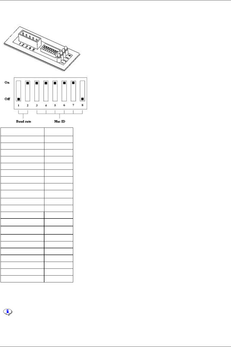
Field bus
Hardware
LED 1: Not used
LED 2: Network status
LED 3: Module status
LED 4: Not used
On = 1
Off = 0
Function Dip switch #
AD0 8
AD1 7
AD2 6
AD3 5
AD4 4
AD5 3
BD2 2
BD1 1
Baud rate (bit/sec) Dip 1 - 2
125k 00
250k 01
500k 10
Reserve (SW-setting) 11
Address Dip 3 – 8
0 000 000
1 000 001
2 000 010
3 000 011
… …
62 111 110
63 111 111
Mac ID (node address)
To set the Mac ID from ToolsTalk PF all DIP switches must be set to “On” (11 111 111).
The Mac ID cannot be changed when the power is switched on.
9836 3123 01 169 (330)

Field bus
Field bus connector
Connector 5-pin 5.08mm detachable screw terminal.
Pin Color code Description
1 Black V-
2 Blue CAN-L
3 Bare Shield
4 White CAN-H
5 Red V+
V- and V+ must come from a fully isolated power supply. That means that the voltage cannot
have any reference to ground. This is to prevent the bus from interference caused by ground
loop problems. If V- and V+ are connected from a Power Focus internal 24VDC (screw
terminal) the same connection shall only power one DeviceNet module. This means that the
DeviceNet cable connected to the PF must not include voltage wires. Normally there is a
central power supply that feeds all nodes in the network.
Power consumption
Current consumption at 24 VDC (V- to V+) is max 70 mA at power up and 25-30 mA continuously.
Functionality of the indication LED’s
The module is equipped with four colours LED’s, used for debugging purposes.
LED number Function Information Condition
1 Not in use
2 Network status Not powered / Not on line Off
2 Network status Link OK on line. Connected Steady green
2 Network status Critical link failure Steady red
2 Network status On line not connected Flashing green
2 Network status Connection time out Flashing red
3 Module status No Power Off
3 Module status Unrecoverable fault Steady red
3 Module status Minor fault Flashing red
3 Module status Device operational Steady green
4 Not in use
Bus termination
The termination of the Field bus requires a terminating resistor at each end. These resistors should have a
value of 121 Ohm.
EDS file
Each device on a DeviceNet network is associated with an EDS file, containing all necessary information
about the device. The network configuration program during configuration of the network uses this file.
Contact the local Atlas Copco service representative for a copy of the EDS file.
File name: pf3devn.eds
170 (330) 9836 3123 01
Field bus
Icon file
Contact the local Atlas Copco service representative to get a copy of the icon file for Power Focus. This
file can be used to have a Power Focus Icon in PLC configuration SW.
File name: pf3devn.ico
13.6 InterBus/InterBus2MB
InterBus is normally used for industrial automation applications, such as valve, sensor
and I/O unit control. InterBus is used in many different types of industry, including:
automobile industry, food industry, building automation, plant construction, paper
converting, wood processing and process engineering.
InterBus has a user organisation called the InterBus Club. The organisation assists members on a wide
variety of matters concerning InterBus. For more information, contact the InterBus Club:
http://www.interbusclub.com
The media used by InterBus is a shielded copper cable consisting of three twisted pairs. Two of these pairs
are used for the bus connection and in the last pair only one cable is used. This cable is used to earth the
bus. The baud rate for the bus is 500 Kbit/s with a total amount of data of 4096 I/O points.
The Power Focus InterBus module is to be used on InterBus remote bus networks. In applications where it
is necessary to exchange large amounts of data and where a parallel application interface is required,
InterBus is the preferred option.
InterBus has two ways of exchanging data. The first way is a fast cyclical I/O data, called process data.
The other is a somewhat slower protocol called PCP, which is mainly used for configuring and setting the
parameters of a device. The Power Focus InterBus module supports up to 10 words on the bus, out of
which none, one, two or four words may be selected to act as the PCP –channel, necessary if the PCP-
protocol required.
The PCP version supported by the module is version 2.0, which is fully backwards compatible.
When using InterBus master boards where the PCP channel is not supported, the maximum
input and output is 20 Bytes in and 20 Bytes out.
Physical interface
Interface Description
Transmission media InterBus two differential lines.
Topology Ring Structure.
Field bus connectors 9 pin male D-sub.
Cable Shielded copper cable, Three Twisted pair.
Isolation The bus is galvanically separated from the other electronics with two DC/DC converters. Bus signals are
isolated via optic couplers.
ASICs and circuits Module is based on SUPI 3 and SRE1 chip from Phoenix contact.
9836 3123 01 171 (330)

Field bus
InterBus module
Variable Limits
Node Address Auto select
Number of nodes in an InterBus network
Baud rate 500 Kbit/sec, 2Mbit/sec
Process string length <= 20 bytes
Parameter string length (send with PCP) 200 byte – Process string length
The string length in the Power Focus is limited to 200 bytes. InterBus standard
allows 512 bytes.
PCP length 0, 1, 2, 4 Words
Parameter data index 0x6000 R/W + I (I = 0, 1, …)
0x6040 RO + I (I = 0, 1, …)
ID code (in PLC side) PCP 0 = 3
PCP 1 = 0xF3
PCP 2 = 0xF0
PCP 4 = 0xF1
Hardware
LED 1 = RBDA (Remote Bus Disable)
LED 2 = TR (Transmit/Receive)
LED 3 = CC (Cable Check)
LED 4 = BA (Bus Active)
BUS-IN (9-pin D-sub male)
Pin Name
Housing PE
1 DO1
2 DI1
3 GND
4 Not used
5 Not used
6 /DO1
7 /DI1
8 Not used
9 Not used
172 (330) 9836 3123 01
Field bus
BUS-OUT (9-pin D-sub female)
Pin Name
Housing PE
1 DO2
2 DI2
3 GND
4 Not used
5 GND
6 /DO2
7 /DI2
8 Not used
9 RBST
Always connect RBST to GND if it is not the last module on the bus. If the RBST is not
connected to GND on the output connector, the Power Focus InterBus module will terminate
the outgoing bus.
Functionality of the indicator LED’s
LED number Name Description
1. RBDA Remote bus disable Active RED when outgoing remote bus is switched off.
2. TR Transmit/Receive Active GREEN when PCP communication is carried out over the InterBus (0.6 s hold
time to be visual).
3. CC Cable check Active GREEN if the cable connection is good and the InterBus Master is not in RESET.
4. BA Bus active Active GREEN. Is monitoring Layer 2.
Icon file
Contact the local Atlas Copco service representative to get a copy of the Icon file for Power Focus. This
file can be used to have a Power Focus Icon in the PLC configuration SW. File name: pf3intb.ico
13.6.1 ModBusPlus
ModBusPlus is a local area network system designed for industrial
control and monitoring applications, developed by Modicon, Inc.
The network enables programmable controllers, host computers and
other devices to communicate throughout plants and substations.
ModBusPlus transfers fast data for motor controllers, MMI, I/O
units and other industrial equipment. ModBusPlus has an
international user organisation called Modicon Inc.
General technical questions regarding the Field bus should be addressed to the local ModBusPlus User
Group in the first instance.
A contact address list is available from the ModBusPlus Internet site http://www.modicon.com
.
9836 3123 01 173 (330)

Field bus
174 (330) 9836 3123 01
Physical interface
Interface Description
Transmission media ModBusPlus uses one differential line (RS-485 twisted pair) and shield.
Topology Token Bus Structure, virtual token ring.
Field bus connectors 9 pin female D-sub.
Cable Shielded copper cable, one twisted pair.
Isolation The bus signals are separated from the other electronics with a transformer according to ModBusPlus
interface description.
ASIC’s and circuits Module is based on chip-set and software from Modicon Inc.
Mechanical overview
ModBusPlus module is a host device. This host device can be read and written to from another
ModBusPlus host device or controller. ModBusPlus module will not initiate any point-to-point
communication to other nodes, it will only respond to incoming commands. It can although broadcast
global data to all nodes on the network.
Protocol and supported functions
ModBusPlus has two ways of exchanging data. One through fast cyclic I/O data called global data, and
one through a somewhat slower ModBusPlus protocol for point-to-point parameter data transfer. The
maximum global data is 32 words on the bus. The point-to-point data transfer is handled by using one of
the following ModBus functions read holding registers, preset single register and preset multiple registers
all 40000 registers.
ModBusPlus module information
Variable Limits Information
Node Address 1 - 64
The node address cannot be
changed during operation.
Source Address 1 - 64 The source address cannot be
changed during operation.
Number of nodes in a ModBusPlus
network
Max 32 (with repeaters 64)
Bus length Max 2000 m with repeaters
Bus cable length Max 500 m
Data address 40001 + I (I = 0, 1, …) From PF
41025 + I (I = 0, 1, …) To PF
(Global data from PF data in the module starts
from address 40001 and point-to-point data starts
immediately thereafter. Global data to PF data in
the module starts from address 41025 and point-
to-point data starts immediately thereafter. For
example, if to PF string length is 8 bytes and to
PF global string length is 4 bytes, the global data
are mapped to address 41025 and 41026; the
point-to-point data are mapped to address 41027
and 41028.)
This address is based on words.
Baud rate Automatic (1Mbit/s) Automatically set from PLC at
connection.
Data to PF total length 0 - 200 bytes
(The string length is in Power Focus limited to
200 bytes. ModBusPlus standard allows 64 bytes
global data and 250 bytes point-to-point data.)
Must be the same in PF and PLC.

Field bus
Variable Limits Information
Data from PF total length 0 - 200 bytes
(The string length is in Power Focus limited to
200 bytes. ModBusPlus standard allows 64 bytes
global data and 250 bytes point-to-point data.)
Must be the same in PF and PLC.
Global string length (To/From PF ) 0 - 64 bytes Must be the same in PF and PLC.
Host Firmware Rev. 77
Hardware
LED 1: Not used
LED 2: Error
LED 3: MBP Active
LED 4: MBP Init
Functionality of the indication LED’s
The module is equipped with four coloured LED’s used for debugging purposes (LED 1 not used). The
function of the LED’s is described in the table and figure below.
Name Color Function
Error
(LED 2)
Red Indicates that the communication is not OK.
Turned Off – communication OK
MBP Active
(LED 3)
Green Indicates different Node Status:
Flashing every 160 ms – This node works normally, receiving and passing token.
Flashing every 1 s - This node is in monitor offline status.
2 Flashing, off 2 s - This node is in MAC IDLE never receiving-token status.
3 Flashing, off 1.7 s - This node is not hearing any other nodes.
4 flashing, off 1.4 s - This node has heard a valid packet that has a duplicated-node address sent from
another node on the network, using the same Node ID.
MBP Init
(LED 4)
Green Indicates that the peer interface is initialised
Turned Off - peer interface is not initialised
Field bus connectors
ModBusPlus recommends the use of a 9 pin female D-sub connector. Depending on the protection class
and type of application, other connector designs may also be used.
Connector 9-pin female D-sub
Pin Name
1 Cable shielding
2 Line-B
3 Line-A
4 PE
9836 3123 01 175 (330)
Field bus
Node address
Node address is set with the first DIP switch on the Field bus module, allowing address settings from 1-64
in binary format. If the set node address is from SW1, ModBusPlus takes SW node address regardless of
hardware switch position.
1 (MSB) 2 3 4 5 6 (LSB) Function
ON ON ON ON ON ON Node address set to 1
ON ON ON ON ON OFF Node address set to 2
ON ON ON ON OFF ON Node address set to 3
- - - - - - -
OFF OFF OFF OFF OFF ON Node address set to 63
OFF OFF OFF OFF OFF OFF Node address set to 64
The Node address cannot be changed during operation.
Source address
Source address is set using the second dip switch (the one close to LED) on the Field bus module, this
enables address settings from 1-64 in binary format. If the set source address is from SW2, ModBusPlus
takes SW source address regardless of hardware switch position.
1 (MSB) 2 3 4 5 6 (LSB) Function
ON ON ON ON ON ON Source address set to 1
ON ON ON ON ON OFF Source address set to 2
ON ON ON ON OFF ON Source address set to 3
- - - - - - -
OFF OFF OFF OFF OFF ON Source address set to 63
OFF OFF OFF OFF OFF OFF Source address set to 64
The source address cannot be changed during operation.
Icon file
It is not necessary for ModBusPlus to install a special file to recognise our product and it does not support
icon files.
13.6.2 EtherNet/IP
Ethernet is one of the most popular network technologies in use today. The
major reasons for the popularity are a suitable mix of speed, cost and ease of
installation. The technology benefits, the market acceptance, and the possibility
to support, more or less, any non-real-time critical protocol, makes the Ethernet
an ideal networking technology for most systems.
More information, as well as links can be found at the web site www.iaona-
eu.com.
176 (330) 9836 3123 01

Field bus
9836 3123 01 177 (330)
Hardware
The module is based on a high performance CPU operating at 66 MHz. It features 8MB RAM and 2 MB
FLASH.
Supported Field bus protocols
ModBus/TCP
The module supports the ModBus/TCP protocol and is conform to the ModBus/TCP specification 1.0.
More information about the ModBus/TCP protocol can be found at
http://www.modicon.com/openmbus/index.html.
EtherNet/IP
The module supports the Ethernet protocol.
Ethernet/IP is based on the control and information protocol, CIP, which is also the framework for both
DeviceNet and ControlNet, to carry and exchange data between nodes. To be consistent with the other
Field bus modules that is based on the CIP, i.e., DeviceNet and ControlNet, the same vendor specific
objects are implemented, together with new objects for servicing and monitoring the IT functionality.
EtherNet/IP module
Variable Limits Information
IP address Do not configure the module to use any of them
0.x.x.x
127.x.x.x
x.x.x.0
x.x.x.255
Devices on an Ethernet network are not
allowed to be configured to the IP
addresses listed in left column
000h + I (I = 0, 1, …) From PF
400h + I (I = 0, 1, …) To PF
The data length is in PF limited to 200 bytes.
ModBus/TCP and EtherNet/IP standard allows
1024 bytes data.
This address is based on words. ModBus/TCP data address
0000h + I (I = 0, 1, …) From PF
4000h + I (I = 0, 1, …) To PF
The data length is in PF limited to 200 bytes.
ModBus/TCP and EtherNet/IP standard allows
1024 bytes data.
This address is based on bits
EtherNet/IP assembly instance Input 100, output 150, configuration 5 and size = 0 This is used to configure a EtherNet/IP
module
Data to PF total length 0 - 200 bytes
The data length is in PF limited to 200 bytes.
ModBus/TCP and EtherNet/IP standard allows
1024 bytes data.
Must be the same in PF and PLC.
Data from PF total length 0 - 200 bytes
The data length is in PF limited to 200 bytes.
ModBus/TCP and EtherNet/IP standard allows
1024 bytes data.
Must be the same in PF and PLC.

Field bus
178 (330) 9836 3123 01
Field bus connectors
The module uses standard Ethernet connector RJ45.
The module uses twisted-pair cables, and no external termination is required.
RJ45 (Standard)
Pin Signal
1 TD+
2 TD-
3 RD+
4 Termination
5 Termination
6 RD-
7 Termination
8 Termination
Status indicators
The module has four status LED’s.
LED State Summary Description
Steady Off Not connected Module is not connected to Ethernet LED 1 - Link
Steady Green Connected Module is connected to Ethernet
Steady Off No power No power applied to the module
Steady Green Device operational Module is operating correctly
Flashing Green Standby The module has not been configured
Flashing Red Minor fault A minor recoverable fault has been detected
Steady Red Major fault A major internal error has been detected
LED 2 - Module Status
Flashing Green/Red Self-test The module is performing a power on self test
Steady Off No power or no IP
address
Module has no power or no IP address
Steady Green Connected Module has at least one EtherNet/IP connection
Flashing Green No connections There are no EtherNet/IP connections established
Flashing Red Connection timeout One or more of the connections in which this module
is the target has timed out. This state is only left if all
timed out connections are re-established or if the
module is reset
Steady Red Duplicate IP Module has detected that its IP address is already in
use.
LED 3 - Network Status
Flashing Green/Red Self-test Module performing a power on self-test.
LED 4 - Activity Flashing Green Active Flashes each time a packet is received or transmitted

Field bus
13.6.3 ControlNet
ControlNet is based on the Control and Information Protocol (CIP), which is
also the application layer for DeviceNet and EtherNet/IP.
The ControlNet module is classified as a ControlNet adapter, i.e., it cannot originate connections on its
own, but a scanner node can open a connection towards it. The module is implemented according to the
ControlNet International specification for a Communication adapter.
ControlNet module is accessible by other nodes via UCMM (unscheduled) messages. Unscheduled
messages are usually used for information such as configuration data.
The module is also equipped with a NAP (Network Access Port) for temporary connection of
configuration tools, e.g. a PC card.
Features
The ControlNet module includes the following features:
ControlNet adapter
Network access port (NAP)
Media redundancy support
Conforms to communication adapter, profile 12
MAC ID can be set via onboard switches or application interface
Up to 450 bytes of I/O data in each direction
UCMM Client/Server support
Galvanically isolated bus electronics
UL & CUL conformance
EDS file
Each device in a ControlNet network is associated with an EDS file, containing information needed for
network configuration. The network configuration tool uses this file during network configuration.
Network Access Port (NAP)
The NAP (Network Access Port) provides temporary access to the ControlNet network for diagnostic and
configuration. (RJ45)
ControlNet channels A & B
The module is equipped with two BNC contacts for connection to ControlNet. If redundant operation is
desired both connectors are used, otherwise connector A or B is used. (BNC)
9836 3123 01 179 (330)

Field bus
Mac ID switches (x10 and x1)
On a ControlNet network, each node must be assigned its own unique node address. The module features
on board switches for Mac ID configuration, providing an address range of 1 – 99.
In the example below the Mac ID is set to 42 (4 x 10 + 2 x 1).
Indicators
ControlNet status indicators indicate run time status and errors to the user.
LED Indication State Description
Green Connection in run state
Green Flashing Connecting connection idle
Red Major fault
1 Module status
Red Flashing Minor fault
Off Module not initialized
Red Major fault
Alternating red/green Self test
2 and 3 Channel A and Channel B
Red Flashing Node configuration error, duplicate Mac ID etc.
Off Channel disabled
Green Normal operation of channel
Green Flashing Temporary error (node will self correct) or not configured
Red Flashing No other nodes, or media fault
2 or 3 Channel A or Channel B
Red & Green Flashing Network configuration error
Off No connection has been opened 4 Module owned
Green A connection has been opened towards the module
13.6.4 Profibus-IO
The embedded Profinet interface is a complete Profinet solution for a Profinet IO
device. All analogue and digital components that are needed for a complete
Profinet IO interface with soft-real time (RT) are mounted on the module. The
module is based on the Siemens Profinet I/O software technology.
The Profinet module works as a I/O-Device on the Profinet network. The module supports up to 512
bytes of IO for both Input and Output data. The module baud rate is 100Mbit/s (full duplex). The IP-
address can be configured either via DHCP (BootP) or DCP. Three diagnostic LEDs will continuously
indicate the actual Profinet status and eventually error messages. The module also supports the normal
Profinet Alarm functionality. In the standard version the module uses a normal RJ45 connector for the
bus connection.
Features
Up to 64 slots / 1 sub slot
Up to 1024 bytes cyclical I/O (512 input & 512 output)
2 ms cycle time
180 (330) 9836 3123 01

Field bus
Indicators
Led Indication State Description
Green Link established
Green flashing Receiving/Transmitting data
1 Link/Activity
Off No link or power off
Green On line, Run
Connection with IO Controller established
IO Controller is in Run state
Green, 1 flash On line, Stop
Connection with IO Controller established
IO Controller in Stop state
2 Communication Status
Off Offline
- No connection with IO Controller
Green Initialized, no error
Green, 1 flash Diagnostic data available
Green, 2 flashes Blink, Used by an engineering tool to identify the Field bus module
Red, 1 flash Configuration Error
Too many modules/submodules
I/O size derived from IO controller configuration is too large
Configuration mismatch (no module, wrong module)
Red, 3 flashes No device name or no IP address assigned
Red, 4 flashes Internal error
3 Module Status
Off No power or not initialized
4 - - -
GSD
On Profinet, the characteristic of a device is stored in an XML data file. This file, referred to as the “GSD”
– file is used by Profibus configuration tool when setting up the network.
Connector
ConnectorRJ45 standard Ethernet connector is used
13.6.5 FL-Net
FL-Net is a control network, primarily used for interconnection of devices like PLCs, Robot controllers,
and Numerical Control Devices. FL-NET has both cyclic data and message data. There is no master on a
FL-Net network; a token communication method is used for data transmission.
The FL-Net network is based on IP/UDP broadcast messages.
The module is classified as a “Class 1” FL-Net node as it can both send and receive cyclic data.
PF only transfer cyclic data and only use area 2.
9836 3123 01 181 (330)
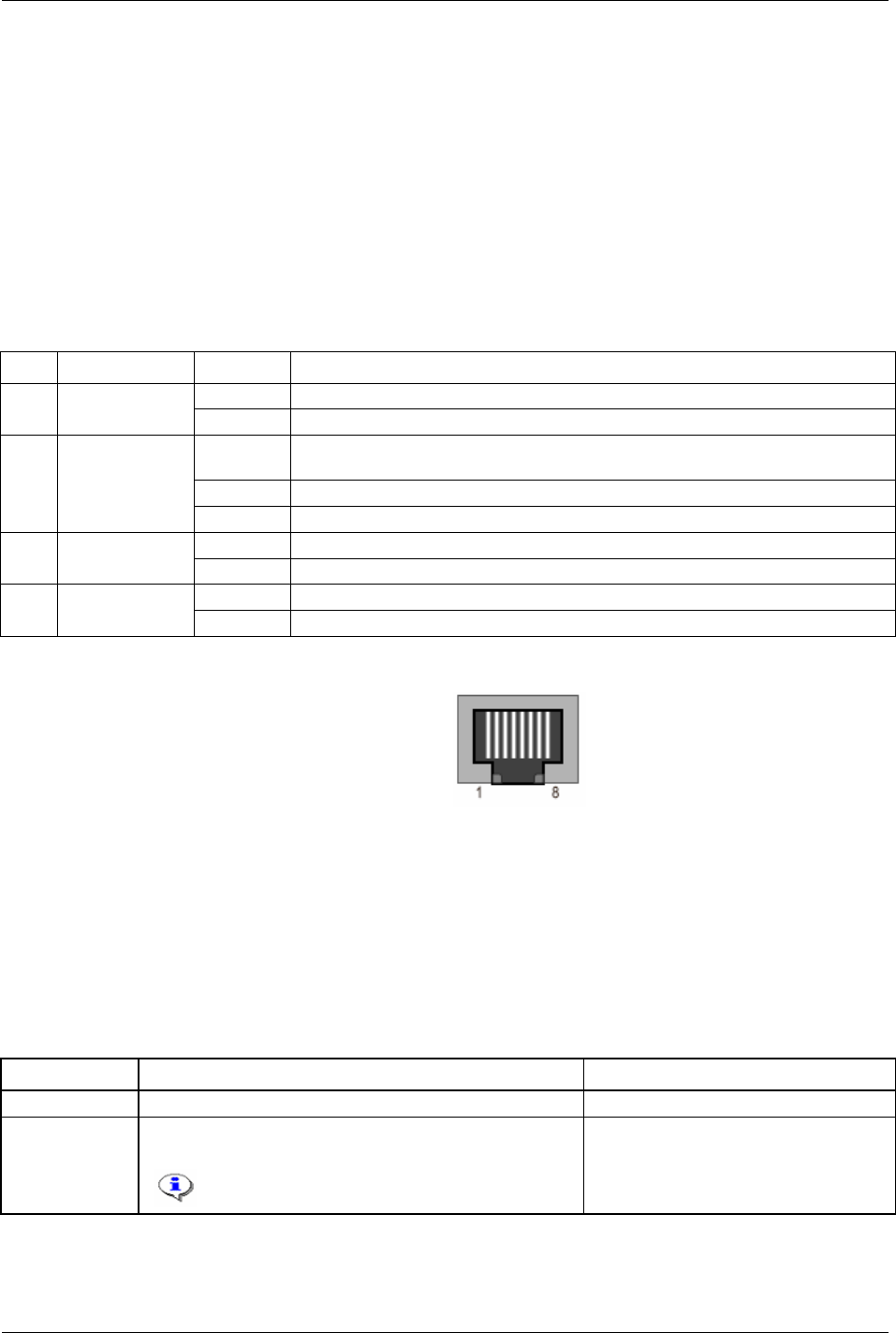
Field bus
Cyclic transfer
FL-Net has two areas for cyclic data, Area 1 and Area 2. These two memory areas are shared by all nodes
on the network. And every node configures the part of the area it will update.
Area 1 is 512 words.
Area 2 is 8192 words.
The cyclic data is mapped to the module I/O area, which maximizes the size of I/O data to 512 bytes in
each direction-for the module.
The time from reception of a token until transmission should not exceed 1.56 ms.
Indicators
Led Indication state description
Green Module is connected to Ethernet 1 Ethernet Link
Off No link
Red Indicates that the unit must be replaced (For example, invalid MAC ID) or Anybus
watchdog in was not updated.
Red, flash Parameter error
2 Error
Off Normal state
Green No activity 3 Activity (COM)
Off Flash green each time a packet is received or transferred
Green Participates in FL-Net 4 FL-Net Link
Off No participation
Connector
ConnectorRJ45 standard Ethernet connector is used
Address dipswitch
A dipswitch with 8 positions is used to configure the low byte of the IP address.
IP configuration
The IP configuration can be set with DIP switch or mailbox message.
Subnet mask is always 255.255.255.0, gateway is not used.
The different IP configuration options (see table below).
Method Description Restriction
Software setting Configure via ToolsTalk PF Software setting overrides the DIP switch.
DIP switch Use 192.168.250.X where X is set with the DIP switch. See
RFC 1918.
This is the preferred method for FL-NET.
Must be set before power on.
182 (330) 9836 3123 01
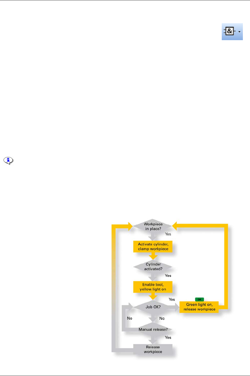
Logic Configurator
14 Logic Configurator
The Logic Configurator is a tool to combine and configure process signals coming from the
screw tightening process or from an external device. It is available in the
Power Focus 4000
hardware only and is programmed over the ToolsTalk PF interface.
At a large automotive plant, to assure the tightening quality, a new pre-assembly station required
communication between the Atlas Copco tightening system and the mechanical fixture. This would
normally have required a PLC. The PF 4000, with its integrated Logic Configurator, solves the problem
by offering basic PLC functions.
The Logic Configurator consists of up to 10 different so called Logic Sets, each denoted with a number (1
to 10, automatically chosen) and a name (25 positions, editable).
Each Logic Set consists of;
the inputs, i.e. selectable events from the Relay status array and the DigIn status arrays
the Instruction list, i.e. the logic gates
the output configuration
Every Logic Configurator circuit instruction list is evaluated every 100 ms which corresponds to a tick or
every time an input status changed.
If one digital input is configured several times, on two IO expanders for instance, the DigIn
function status is the OR result of both digital inputs.
The Relay or DigIn are of the type tracking or pulse. The pulse types are reset after one
tick. Example; OK relay is pulsed after an OK tightening and goes low after 100 ms. Reset
batch input is pulsed when activated and goes low after 100 ms.
14.1 Process description (an example)
When a work piece is positioned, a proximity
switch in the fixture detects its presence. The
work piece is held in position an air cylinder.
The position “work piece fixtured” is
detected by a second proximity switch.
When the tow proximity switches “work
piece in place” and work piece fixtured” are
active, the tightening operation can begin.
After finalizing the tightening operation, a
green lamp lights and stays alight t indicate
the OK result to the operator.
9836 3123 01 183 (330)

Logic Configurator
184 (330) 9836 3123 01
14.2 Logic operators and function blocks
14.2.1 Abbreviations
Abbreviation Description
AND Logical AND operator
OR Logical OR operator
NAND Logical NAND operator
NOR Logical NOR operator
XOR Logical XOR operator
XNOR Logical XNOR operator
TON Timer ON
TOF Timer OFF
TP Timer Pulse
DELAY Delay
TPR Timer pulse Reset
CTU Counter up
CTD Counter down
CTUD Counter up down
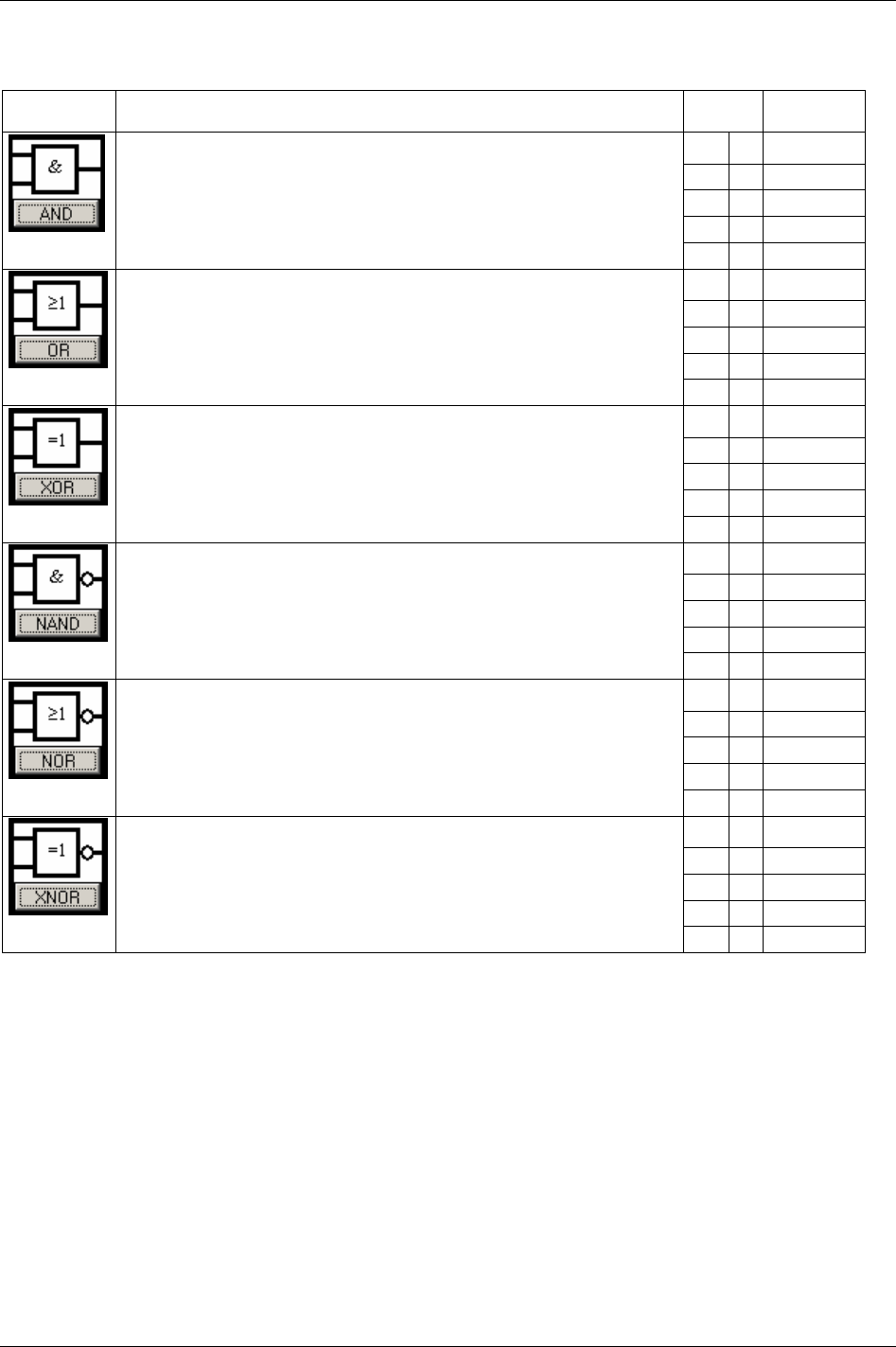
Logic Configurator
14.2.2 Logic gates
Symbol Description Input Output
A B A AND B
0 0 0
0 1 0
1 0 0
The output signal is HIGH only if both inputs to the gate are HIGH.
If neither or only one of the inputs is HIGH, the output is LOW.
1 1 1
A B A OR B
0 0 0
0 1 1
1 0 1
The output signal is HIGH if one or both inputs to the gate are HIGH.
If neither of the input is HIGH, the output signal is LOW.
1 1 1
A B A XOR B
0 0 0
0 1 1
1 0 1
The output signal is HIGH if one, and only one of the inputs to the gate is HIGH.
If both inputs are LOW or both are HIGH, the outputs signal is LOW.
1 1 0
A B A NAND B
0 0 1
0 1 1
1 0 1
The outputs signal is LOW only if both the inputs to the gate are HIGH.
If one or both inputs are LOW, the output signal is HIGH.
1 1 0
A B A NOR B
0 0 1
0 1 0
1 0 0
The output signal is HIGH output results if both the inputs to the gate are LOW.
If one or both input is HIGH, the outputs signal is LOW
1 1 0
A B A XNOR B
0 0 1
0 1 0
1 0 0
The outputs signal is HIGH if both inputs to the gate are the same.
If one but not both inputs are HIGH, the outputs signal is LOW.
1 1 1
9836 3123 01 185 (330)
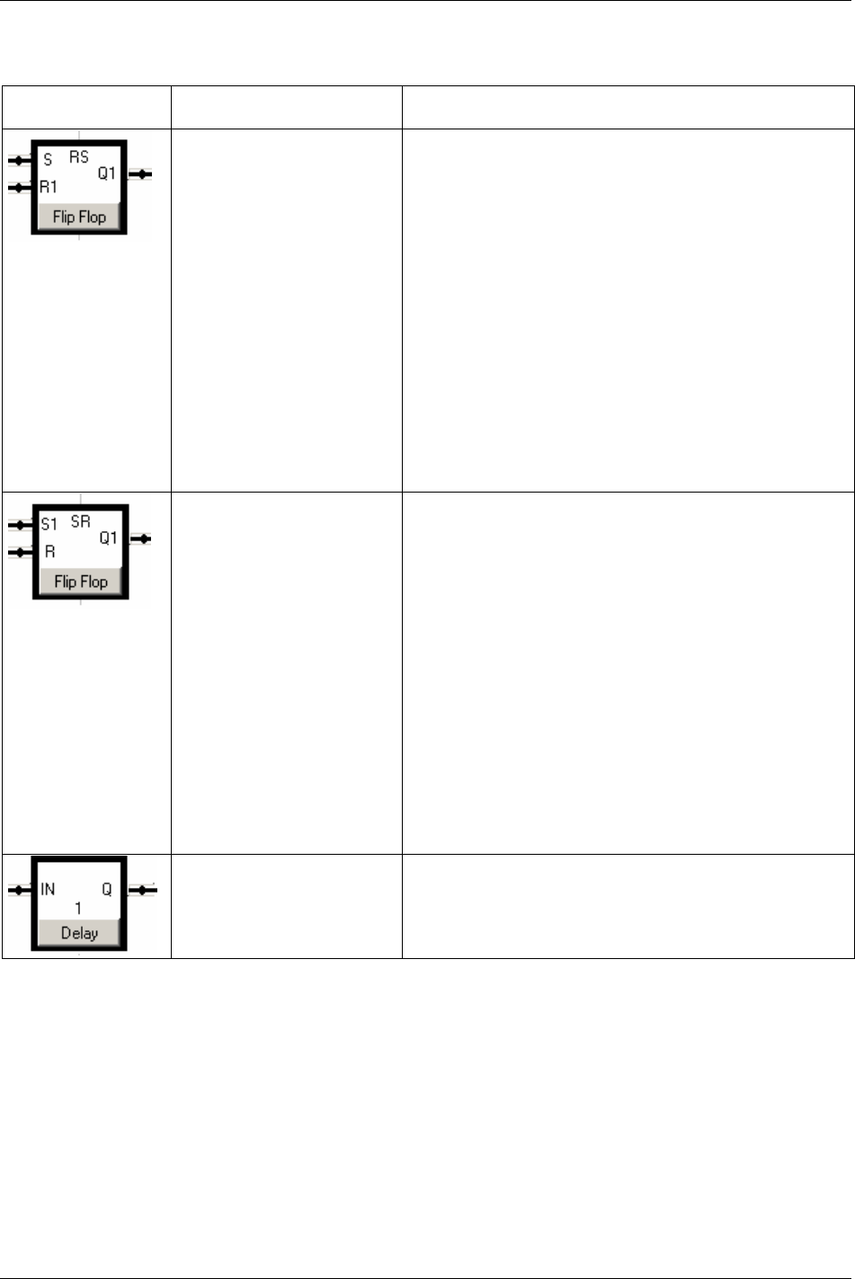
Logic Configurator
14.2.3 Function blocks
Symbol Name Description
Flip Flop Reset Dominant
(Flip Flop (RS)
The Flip-flop gate is also called latch or bi-stable relay and acts like
a memory.
R and S stand for Reset and Set. The stored bit is present on the
output marked Q1.
If S receives a positive pulse while R1 is low, then the Q1 output
goes high, and stays high when S returns low.
If R1 goes high while S is low, then the Q1 output is forced low,
and stays low when R1 goes inactive.
If both R and S are high, the output Q1is forced to low; since
priority is given to the R1 input.
S R1 Q1
0 0 Keep state (memory)
1 0 1
0 1 0
1 1 0 (reset dominant)
Flip Flop Set Dominant
(Flip Flop SR)
The Flip-flop gate is also called latch or bi-stable relay and
acts like a memory.
R and S stand for Reset and Set. The stored bit is present on the
output marked Q1.
If S1 receives a positive pulse while R is low, then the Q1 output
goes high, and stays high when S returns low.
If R is pulsed high while S1 is held low, then the Q1 output is
forced low, and stays low when R returns low.
If both R and S are set high, the output Q is forced to low; since
priority is given to the R input.
S R1 Q1
0 0 Keep state (memory)
1 0 1
0 1 0
1 1 1 (set dominant)
Delay The Delay is implemented as a shift register. It has a preset timer
(delay time) multiple with the PLC tick.
PT stands for Preset Time and is configurable.
186 (330) 9836 3123 01
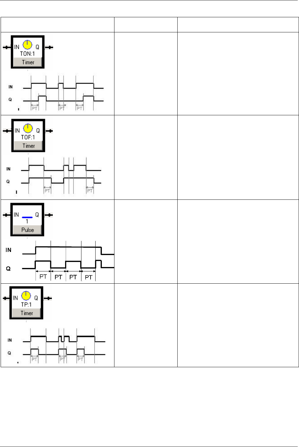
Logic Configurator
Symbol Name Description
Timer ON (TON) The output Q is triggered only if the input IN is
held high during at least Present Time (PT). The
output Q goes low when the input IN goes low.
Timer OFF (TOF) Q is triggered every time the input IN receives a
positive flank The output is high during Present
Time (PT) after the input IN has gone low.
Pulse Present Time (PT) corresponds to the pulse ON
and OFF time.
The pulse frequency is equal to f = 1 / (2 * PT) Hz
The output Q is active while the input IN is high.
Timer Pulse (TP) Q is triggered for Present Time (PT) after a
positive flank.
Note that if the new input up flanked takes place
while Q is high it will be ignored.
9836 3123 01 187 (330)

Logic Configurator
Symbol Name Description
Timer Pulse Reset (TPR) Q is triggered for Present Time (PT) after a
positive flank.
Note that if a new positive flank is received while
Q is high, the “on” timer will be reset and the
output will be held high for a new PT time.
Counter Up (CTU) The CTU has one output Q.
PV is the preset value of the counter i.e. the
counter value to reach for the output to be forced
high.
The counter up has a current counter value CV.
When CV is equal to PV the output Q goes high.
CV is incremented after every positive flank of the
CU input
Note that if CV = PV, then CV is not incremented.
CV is reset after a positive flank on the input R.
The output Q is kept high while CV = PV and until
R receives a positive flank
Counter Down (CTD) The CTD has one output Q.
PV is the preset value of the counter i.e. the start
value of the counter.
The counter down has a current counter value CV.
When CV is equal to zero the output Q goes high.
CV is decremented after every positive flank of the
CD input
Note that if CV = 0, CV is not decremented.
CV is reloaded (CV is set equal to PV) after a
positive flank on the input LD.
The output Q is kept high while CV = 0 and until
LD receives a positive flank.
188 (330) 9836 3123 01
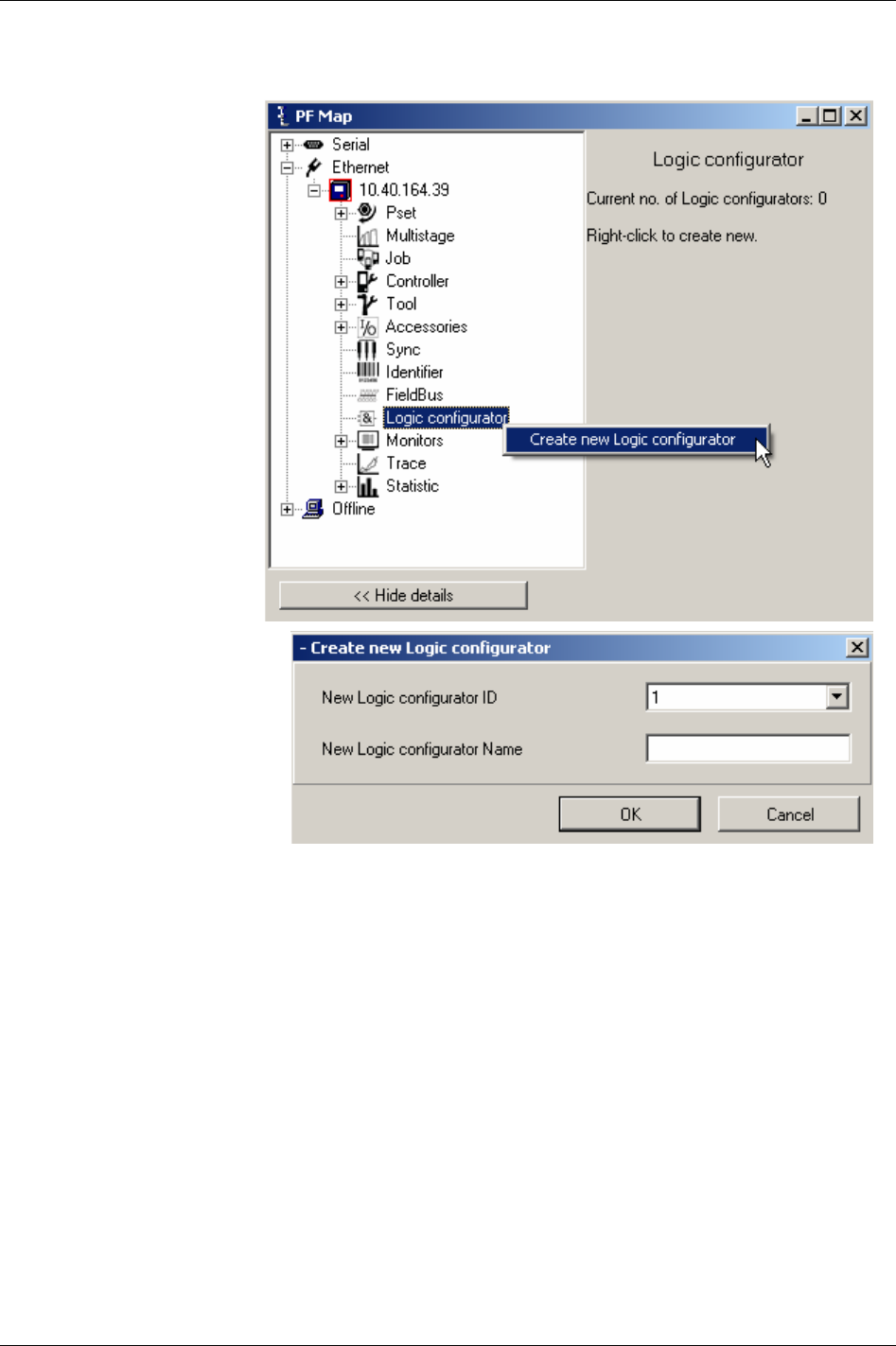
Logic Configurator
14.3 Logic Configurator setup
The first step to program the
Logic Configurator is to open
a Logical Set.
Right-click Logic
Configurator in the PF Map
and select
Create new Logic
Configurator
.
ToolsTalk proposes an ID no.
for the new Set, but this can also
be chosen by the user.
Select a name that relates to the
function the Logical Set should
have.
Click
OK to confirm.
A warning appears.
Click
OK.
9836 3123 01 189 (330)
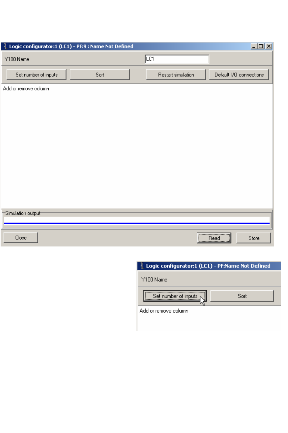
Logic Configurator
A new window appears where the next step is to define the number of inputs for the Logical Set.
Click
Set number of inputs.
190 (330) 9836 3123 01
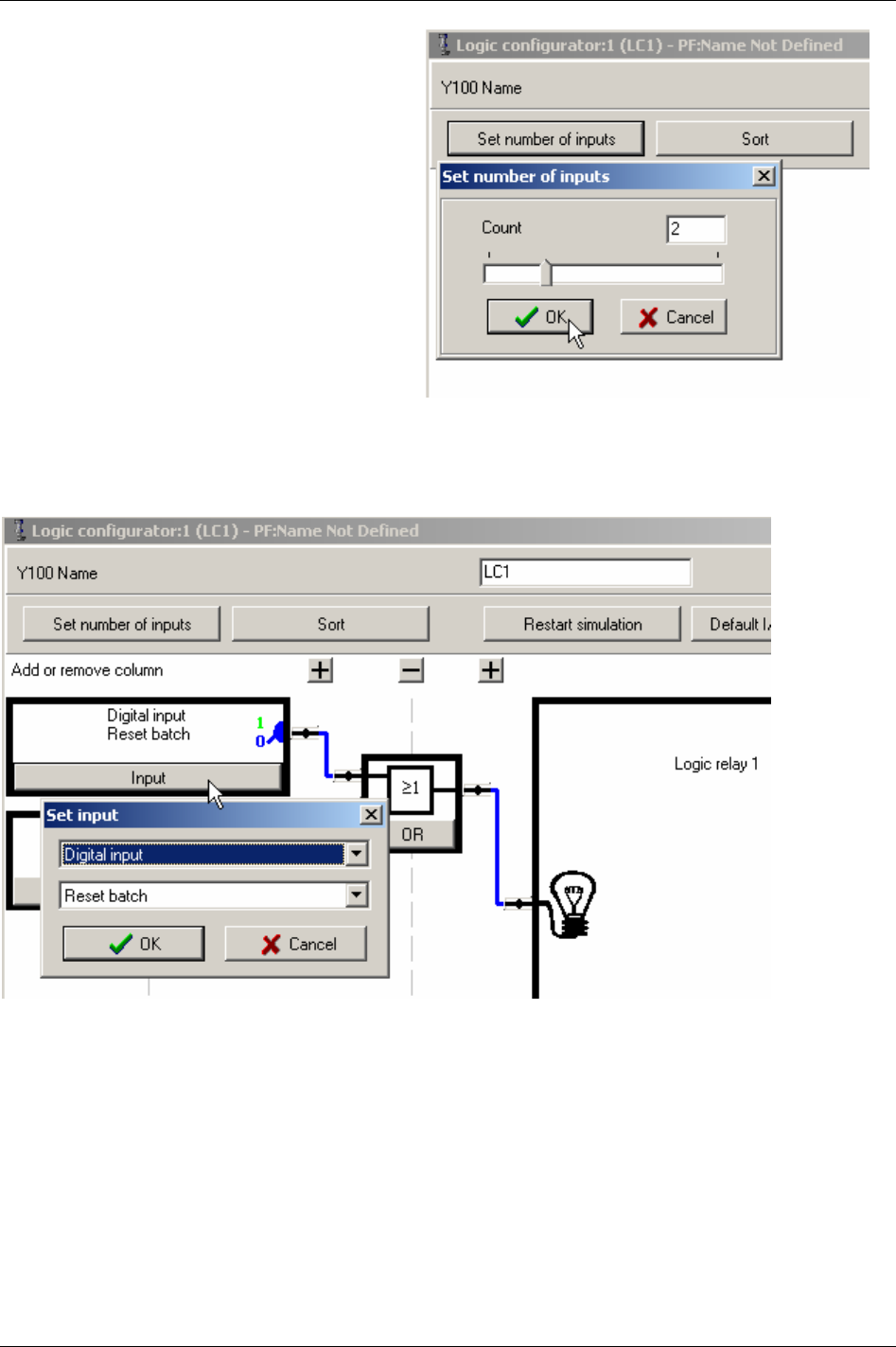
Logic Configurator
Move the slide bar (or type number directly) to
set an input count.
Click
OK. A new window appears that shows the
layout of the Logical Set with the selected
number of inputs.
Click OK again to reach the setup window.
Now it is time to configure the inputs, outputs
and logical gates.
Let’s start with the inputs. Click on the Input key to select the input event. By selecting Digital input
from the first drop-down menu, the events tied to the inputs of the Power Focus can be reached.
If choosing Digital outputs, the list of events will contain the signals generated in the Power Focus.
9836 3123 01 191 (330)
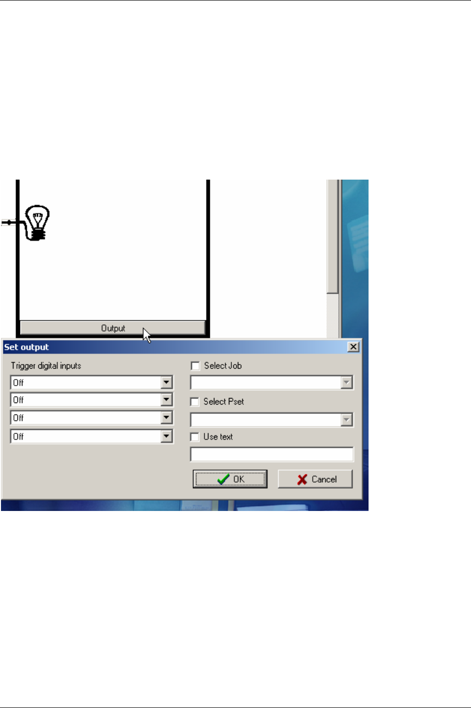
Logic Configurator
Next, let’s define what the output signal of the Logical Set should be used for.
If the output signal should be used as input to another Logical Set, or be put out directly on a physical
Relay, no action is required in this window. The output signal from the Logical set is automatically
labelled “Logic Relay #”, where “#” is the number of the Logical Set. The signal “Logic Relay #” is
available in the drop-down menu of e.g. the Relay setup window under “Accessories” in the PF Map.
If the output of the Logical set should be used for other purposes, click on the
Output. Then select up to
four events under
Trigger digital inputs, or one of the three quick choices (Select Job, Select Pset and Use
text
).
Click
OK when finished.
192 (330) 9836 3123 01
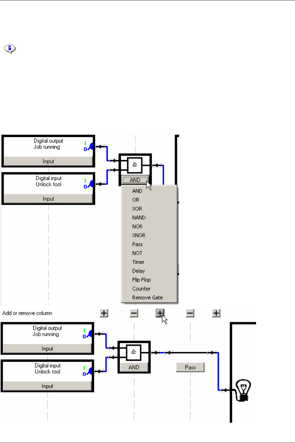
Logic Configurator
Now the logical grid remains to be set up.
By clicking on the keys in the gate symbol, a drop-down menu showing the logic functions appear.
See table in section
Logic gates for a description of the available gates (AND, OR, XOR,
NAND, NOR, XNOR).
See table in section
Function blocks for a description of the available functions (Pass, NOT,
Timer, Delay, Flip Flop, Counter).
Select the gate and where applicable, the timer or counter value.
If the depth of the grid (right-to-left) needs to be increased for your functionality, click on the
Plus icon to
insert a new level. To reduce the depth of the grid, click the corresponding
Minus sign.
Click on the
Plus icon to insert a new element. (Click on the Minus icon to delete an added element.)
9836 3123 01 193 (330)
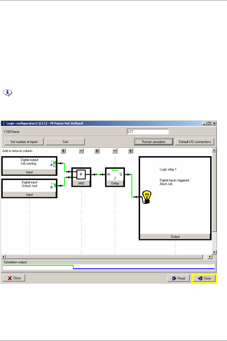
Logic Configurator
14.3.1 Simulation
The Logic Configurator features an off-line simulator that helps verifying the logical grid. The line at the
lower part of the window is blue and low as long as the input settings and logic gates result in a LOW
output signal. When the inputs and the grid result in a HIGH output signal, the line turns green and alters
to the high position. The transitions up and down of the simulator will shift to the right in the window
due to the time factor.
Correspondingly, the colours of the connections in the logical grid changes colour – blue when inactive
and green when active.
Manipulate the simulator input signals by clicking on the switch symbol in the input blocks. One click
will toggle the status of the signal between HIGH and LOW.
Click the Restart simulation key to clear (set zero) all signals.
Click
Store to save all settings.
194 (330) 9836 3123 01
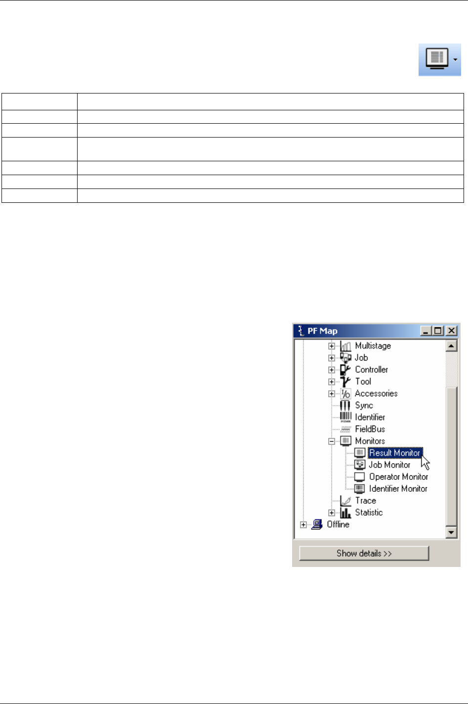
Monitors
15 Monitors
ToolsTalk PF provides a number of monitors designed to present extensive information about
the various functions of Power Focus (see the table below).
Function Description
Result monitor Result monitor displays tightening results and statistics.
Job monitor Job monitor displays Jobs and provides functionality for managing Jobs.
Operator monitor Operator monitor displays tightening result information, also containing graphic representation such as
charts and status indicators.
Picture monitor Picture monitor displays a visual description of the tightening process, suitable for training purposes.
Get all results Get all results displays result information stored in the Power Focus and export possibilities.
Trace Trace displays detailed chart information from the latest tightening.
There are different ways to open monitors:
In the main Menu list, select
Window -> Activate -> Result.
In the
PF Map, expand the Monitors branch and double-click on the monitors.
On the Toolbar, use the drop menu to the right of the
Monitor icon.
15.1 Result Monitor
In the PF Map Monitor branch, double-click on Result Monitor.
9836 3123 01 195 (330)
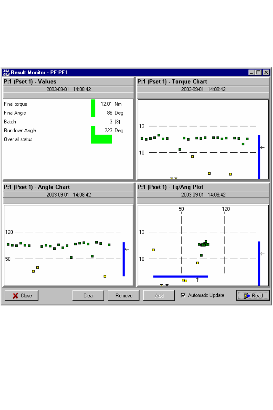
Monitors
The Result Monitor presents the latest tightening results from the Power Focus and the used Pset.
The tightening result includes the Final torque, Final angle, Overall status, Torque chart and Angle chart.
Select between Torque Chart, Angle Chart or Torque/Angle Plot to display results for a unique Pset.
It is possible to display several windows with different views, with a maximum limit of four.
196 (330) 9836 3123 01
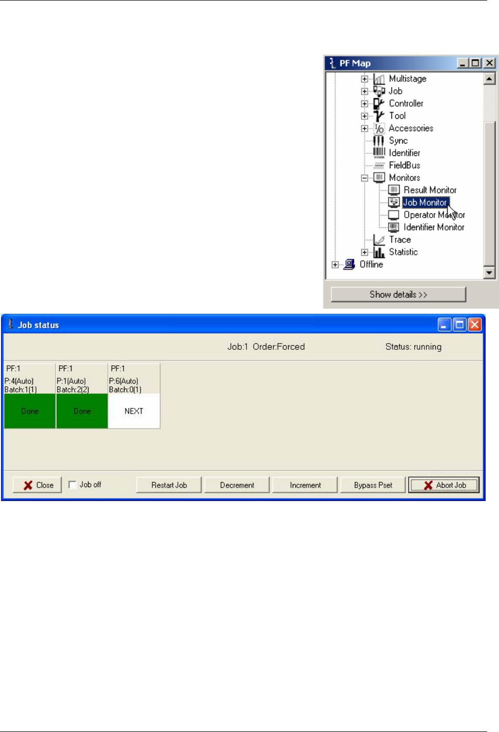
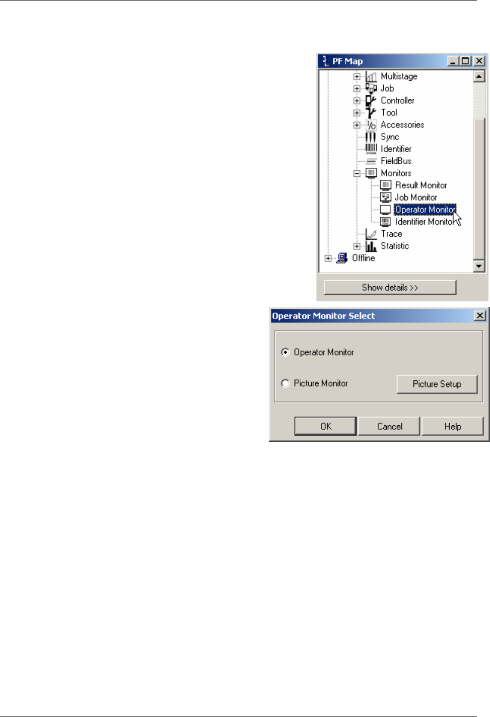
Monitors
15.3 Operator Monitor
In the PF Map Monitor branch, double-click on Operator Monitor.
Select
Operator Monitor.
Click
OK and the monitor appears (see figure and table on
next page).
198 (330) 9836 3123 01
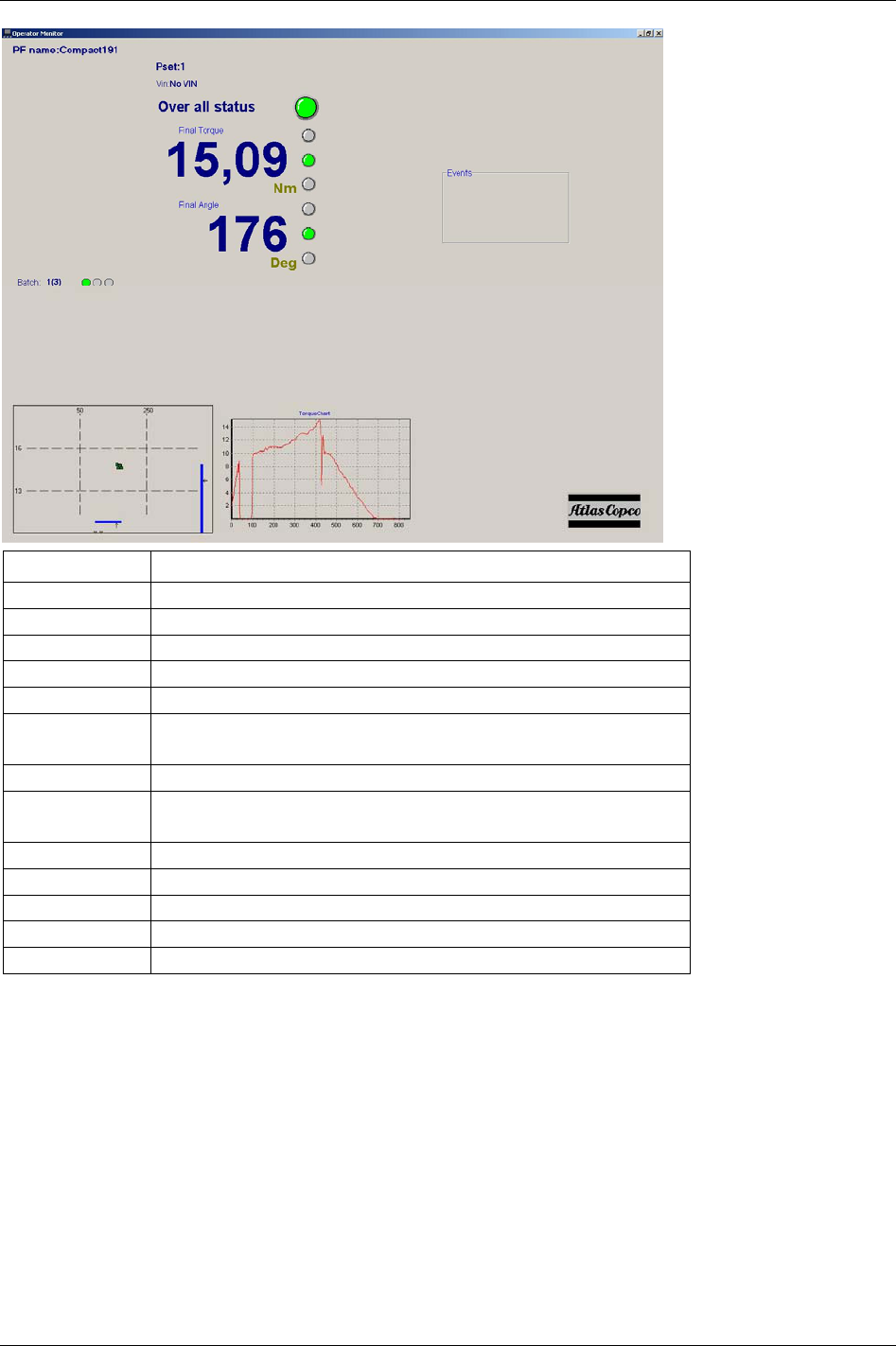
Monitors
Part Description
PF name Name of the PF.
Pset Pset used to perform the tightening.
VIN Vehicle Identification Number.
Overall status Indicator for the overall status of the tightening.
Final torque Final torque of the tightening.
Final torque status Status-indicator for final torque.
(yellow-low/ green-OK/red-high)
Final angle The final angle of the tightening.
Final angle status Status-indicator for the final angle.
(yellow-low/ green-OK/red-high).
Batch The order of the current operation in the batch.
Batch order The overall status of the respective operation in the batch.
Plot chart Displays the final torque and final angle, relative to the acceptance window.
Torque chart Displays the torque as a function of time.
Events Warnings and events.
9836 3123 01 199 (330)
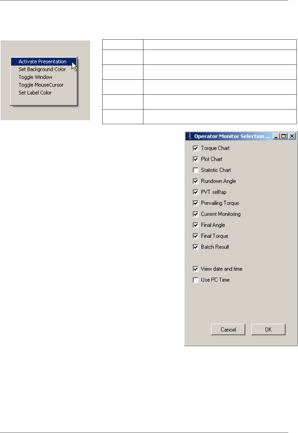
Monitors
Right-click anywhere in the window to open the Options menu.
Option Description
Activate
presentation
User preferences for the content of the operator monitor.
Set background
Color
The option to set the background colour of the operator monitor.
Toggle
window
Toggle mouse
cursor
Set label
colour
Option of setting the label colour for the operator monitor.
Choosing
Activate Presentation the user customises the
information shown in the Operator Monitor by checking the
boxes.
Click OK.
200 (330) 9836 3123 01
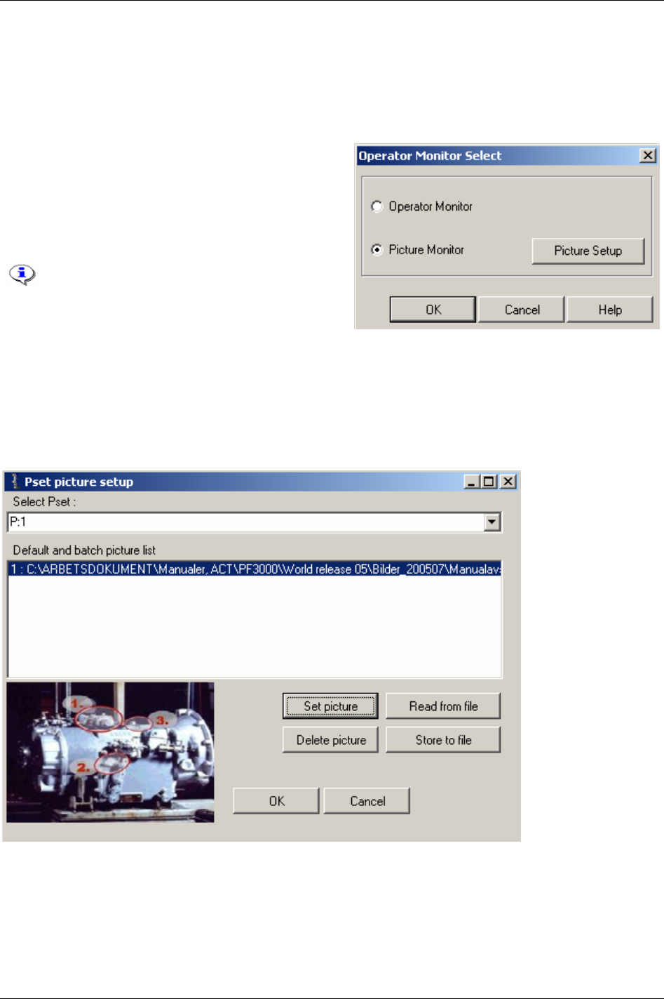
Monitors
15.3.1 Picture Monitor
The Picture Monitor is a feature that gives the user visual guidance throughout the Job sequence. The next
tightening (Pset) in a running Job can be presented graphically with an image (e.g. a picture of the area
where a bolt is placed).
To open the picture monitor, select
Picture Monitor and
click
OK.
To edit Picture Monitoring, click
Picture Setup.
Click
Set Picture and select an image-file using the file
selector window.
The user has the possibility to associate an
image-file with a Pset (available format;
“*.jpg”, “*.bmp”, “*.ico”, “*.emf” and
“*.wmf”). Select a Pset from the list.
To import saved settings for the picture monitor, click
Read from file.
To save the settings click on
Store to file. A save as-window will appear and the user can choose where to
store the file containing the settings.
When finished click
OK.
9836 3123 01 201 (330)
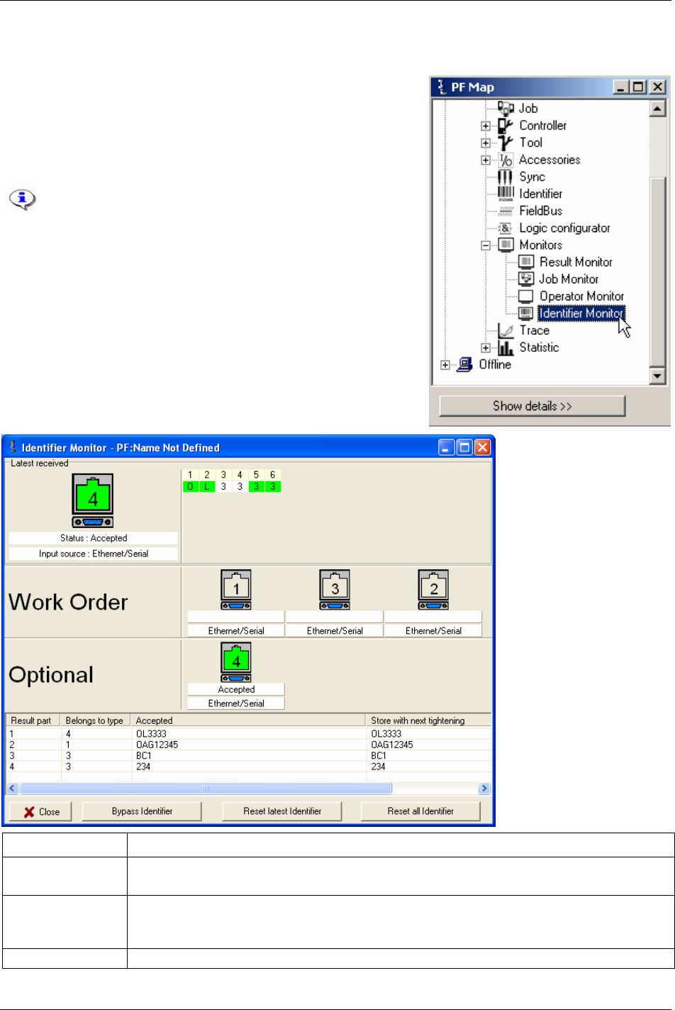
Monitors
15.4 Identifier Monitor
In the PF Map Monitor branch, double-click on Identifier Monitor.
Identifier monitor displays the status (accepted/not accepted) of
the identifier included in the
Work order and Optional identifier
(not included in work order). For more information, see chapter
Identifier.
In the example below, all Identifier input sources are
set to “Ethernet/serial”.
Function Description
Bypass identifier Skips a specified identifier type in a work order.
If a type is not included in the work order, bypassing the first type in the work order is not possible.
Reset latest identifier The latest accepted identifier string is cleared with the command (or digital input) “Reset latest
identifier”.
It is not possible to perform “reset latest identifier” for the last type in a work order.
Reset all identifier All accepted identifier strings are cleared with the command (or digital input) “reset all identifiers”.
202 (330) 9836 3123 01
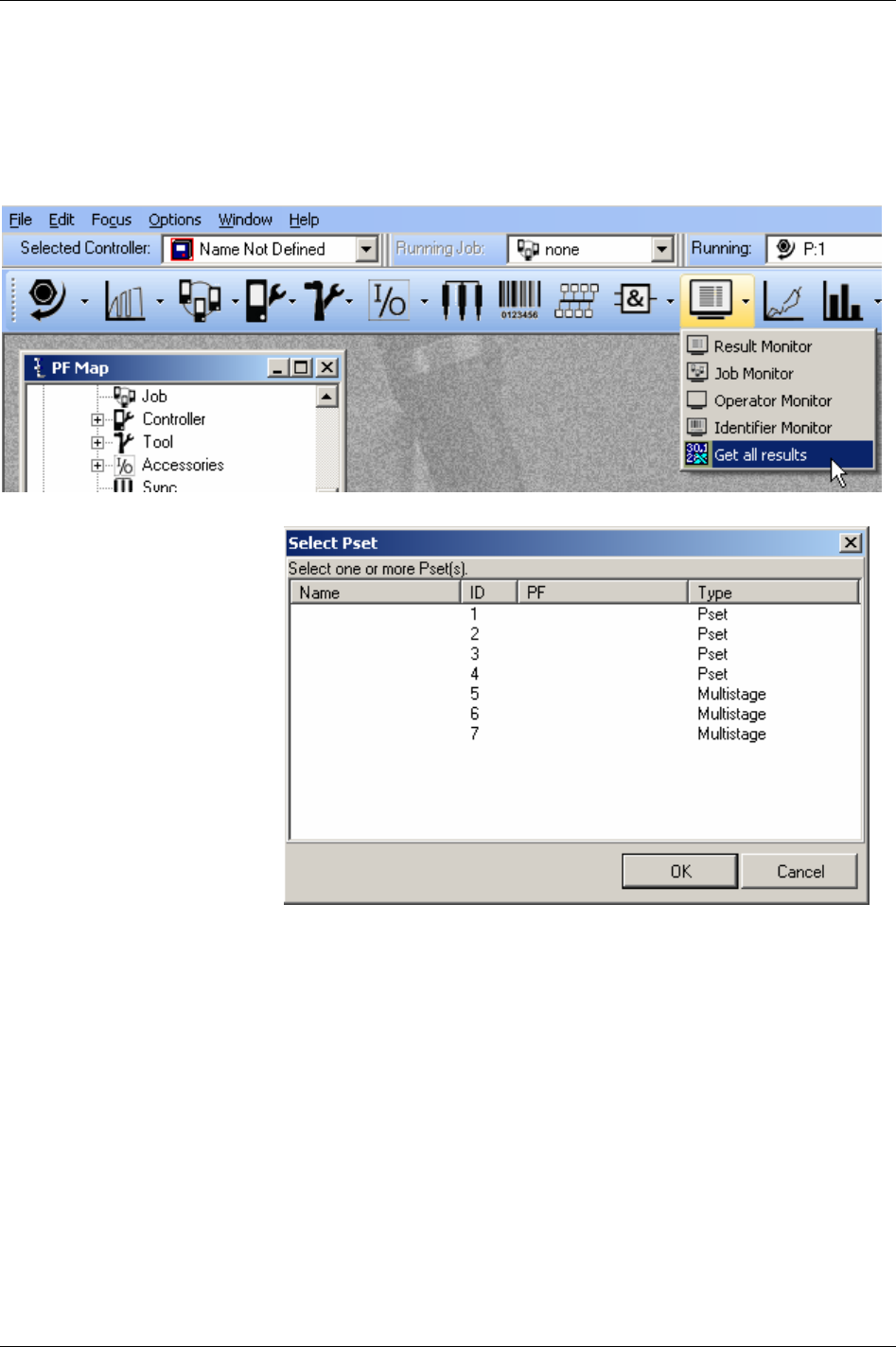
Monitors
15.5 Get all results
Power Focus can store up to 5000 individual tightening results. With the Get all results option, the user is
able to retrieve and view these. The user also has the choice of saving them to a text file or an Excel file.
In the Toolbar, select
Get all result.
Choose a specific Pset or
Multistage and click
OK.
9836 3123 01 203 (330)
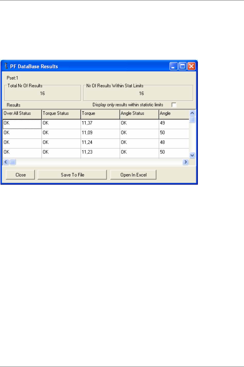
Monitors
The tightening results from that Pset/Multistage appear. Picking up data will take some time depending on
the type of connection and the number of results.
By choosing
Save to file the results are saved into a text file.
The user can also choose to open and view the results in Microsoft Excel by selecting
Open in Excel. This,
of course, requires a properly installed version of Microsoft Excel.
204 (330) 9836 3123 01
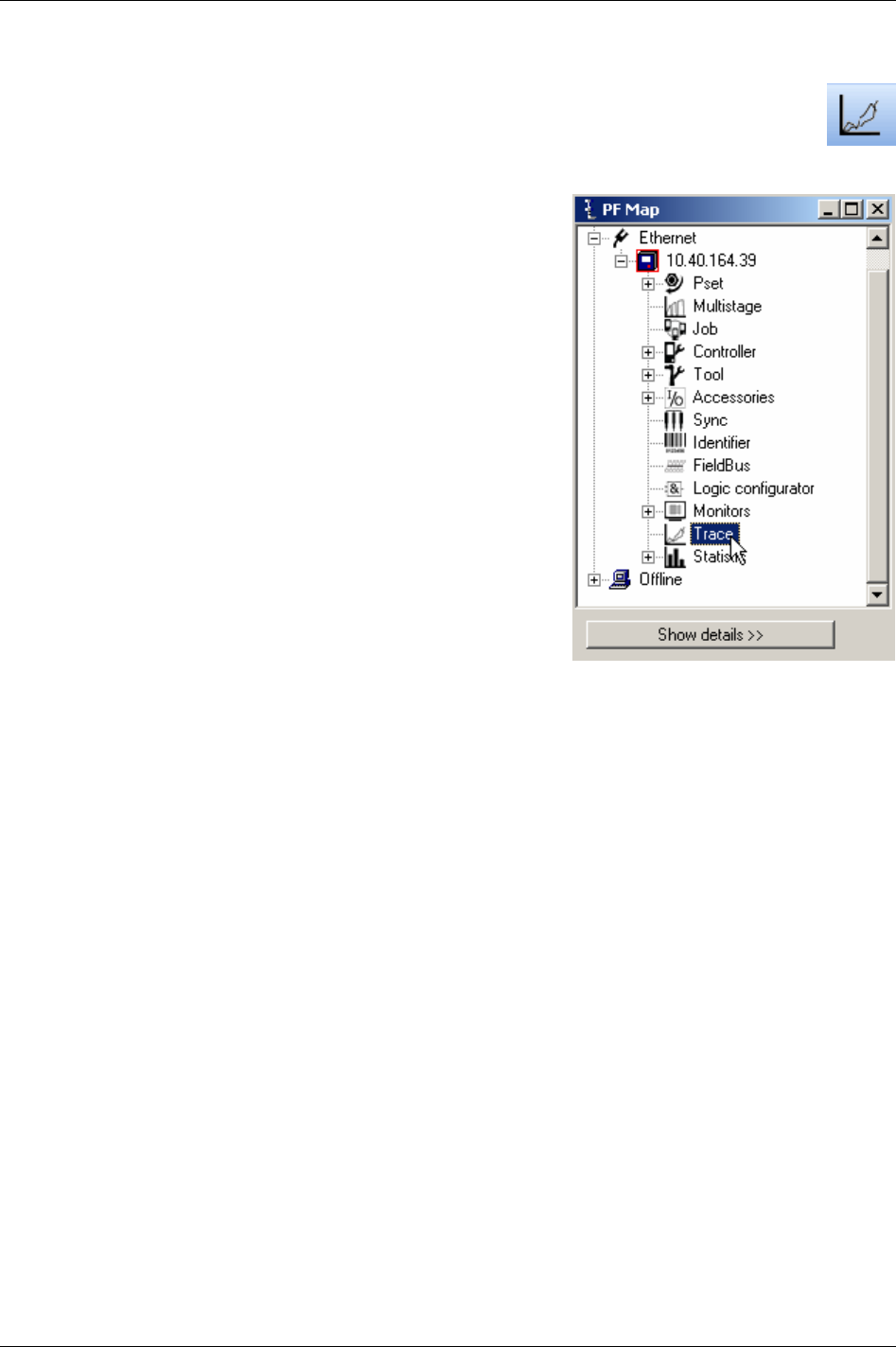
Trace
16 Trace
ToolsTalk PF provides a Trace function designed to present extensive information about the
tightenings.
There are three different ways to open the Trace monitor:
In the
PF Map, and double-click Trace.
In the main Menu list, select
Window -> Activate -> Trace.
Click the
Trace icon on the Toolbar.
9836 3123 01 205 (330)
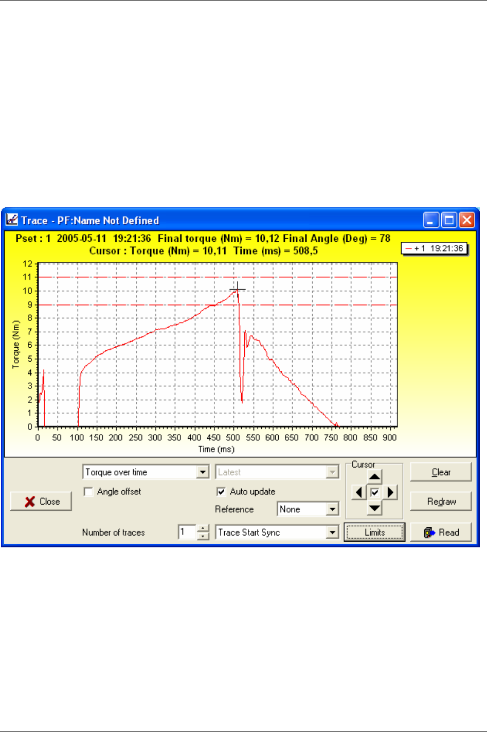
Trace
The trace window appears.
Select which type of chart to view;
Torque over time, Angle over time, Speed over time, Torque and angle
over time
, Torque over angle, Torque and Speed over time.
With
Angle offset selected, Trace views graph from Start final angle [P120] torque value. If deselected,
Trace views graph from
Cycle start [P110] torque value.
With
Auto update selected the charts will automatically update as new tightening data arrives. If
deselected, the user can choose between viewing; latest, latest OK, second latest OK, third latest OK,
latest NOK, second latest NOK, and third latest NOK tightening (NOK is an acronym for not OK).
The Limits function allows the user to customise the limits in the chart. The selections are min max,
selftap, PVT, rundown and CM.
206 (330) 9836 3123 01

Statistic
17 Statistic
17.1 Statistic in Power Focus
The Power Focus statistics are measured after each tightening and can be shown on the display in real time
and be sent to a PC via serial or Ethernet connection. It is also possible to send statistical reports to a
printer for printout. There is a stat alarm LED on the front panel of the PF.
Statistics are calculated based on the following result parameters:
Result Unit Description
Torque Nm* Final torque in selected tq presentation unit.
Angle Deg Final angle in degrees.
* = Other units can be used.
The following statistical results are calculated and displayed for torque and angle parameters:
Results Description
# Results Total number of results that the stat calculations are based on for the analysed Pset.
Min Lowest result in analysed Pset
Max Highest result in analysed Pset
R Range (Max - Min)
Low % low tightenings in analysed Pset
OK % OK tightenings in analysed Pset
High % high tightenings in analysed Pset
X
The mean value for the selected Pset
σ
Sigma. Shows the calculated standard deviation.
X
-3 σ
Mean - 3 sigma
X
+3 σ
Mean + 3 sigma
6 σ
6 sigma
Cr Cr is a calculated viability number (capability). The lower the value, the better the process.
Cp Cp is a viability factor. The higher the value the better process.
Cpk Cpk is a viability factor. The higher the value the better process.
Cam Viability factor. The higher the value the better the process.
9836 3123 01 207 (330)

Statistic
Sub-group results Description
Min Lowest result in the latest completed subgroup
Max Highest result in the latest completed subgroup
R Range for the latest completed subgroup
x
Mean value for the latest completed subgroup
σ
Sigma for the latest completed subgroup
Other definitions Description
R
Mean of subgroup range (number of subgroups)
X
Mean of subgroup mean (number of subgroups)
17.1.1 Statistical process control (SPC)
In order to rapidly detect changes in the process, Power Focus is equipped with a number of statistical
alarm limits based on the
x
and R calculations for torque and angle.
Statistical Process Control (SPC) functions are used on torque and angle.
All checks are performed on the Pset that the tool is currently running with.
If any of the following criteria are true the stat alarm light, and a relay (if used), is activated. The tool may
still run even if an alarm is issued. The alarm is only a warning. The alarm signals remain active until the
process falls within all limits again or the result memory is cleared. This means that the alarm does not
switch off during tightening.
17.1.2 Statistic alarm
x
> UCL
x
< LCL
R > UCL
R < LCL
Cp < 2.0
Cpk < 1.33
SPC
x
and R compared with LCL / UCL alarms cannot function until the LCL and UCL have been
programmed.
208 (330) 9836 3123 01

Statistic
17.1.3 Trend deviation alarm
Trend deviation check and alarm are measured and compared against X-bar and the range for the currently
used Pset.
7 points consecutively increasing
7 points consecutively decreasing
7 points consecutively above average (
X
and / or
R
)
7 points consecutively below average (
X
and / or
R
)
1 point outside
X
or
R
± 2 sigma (sigma for the whole population)
Point = subgroup
The mean is the average of
x
and r
X
and
R
). This means that the SPC trend alarms cannot function until
the number of tightenings in the memory corresponds with the user-specified number of subgroup
parameters.
17.1.4 Calculation of UCL and LCL
Power Focus calculates recommended values for UCL and LCL. The operator can then choose if he wants
to use these values or enter another value.
Subgroup size, Subgroup frequency and number of subgroups parameters are used in the calculations.
17.1.5 Calculation of
X
and
R
Power Focus calculates recommended values. The operator can then choose if he wants to use these values
or enter another value. Sub group size, subgroup frequency and number of subgroups parameters are used
in the calculations.
17.1.6 Calculation formulas
When a stat display is requested, the whole memory will be calculated. This will also be done when
shifting Pset.
Power Focus controls the lowest and highest values. If some of these drop out from memory once it is full
(first in – first out), the entire memory will be recalculated.
The formula for group range is calculated after each completed subgroup.
The formulas for the statistic parameters used by Power Focus:
X
i
= value
n = number of tightenings
Min = minimum value from all the tightenings in the Power Focus memory
Max = maximum value from all the tightenings in the Power Focus memory
minl = minimum acceptable value
maxl = maximum acceptable value
R
ange
R
M
ax
M
in== −
9836 3123 01 209 (330)

Statistic
⎥
⎦
⎤
⎢
⎣
⎡
==
∑
=
n
i
i
X
n
XMean
1
1
⎥
⎦
⎤
⎢
⎣
⎡
−
⎟
⎠
⎞
⎜
⎝
⎛
−
==
∑
=
−
2
1
2
1
1
1
xnX
n
n
i
i
n
s
σ
CR
Maxl Minl
=
−
6*
σ
CP
Maxl Minl
=
−
6*
σ
⎥
⎦
⎤
⎢
⎣
⎡
−−
=
σσ
*3
,
*3
min
MinlXXMaxl
CPK
Tightenings
X
1
X
2
X
3
X
4
X
5
X
6
X
7
X
8
X
9
X
10
X
i
X
i+1
X
i+2
X
i+3
X
i+4
X
i+5
X
i+6
X
i+7
X
i+8
X
i+9
X
i+10
X
i+11
X
i+12
X
i+13
X
i+14
X
i+.. ...
A subgroup is a group of tightenings. Subgroup size is freely programmable and in the example above it is
set to 5, which means that all values in the same group range from i to i+4.
X-bar is the calculated average of the last completed subgroup.
Subgroup size =Group size = z
],,,,,min[],,,,,max[
],,,,,min[],,,,,max[
2212211
1121
zizizizizizin
ziiiziiin
XXXXXXW
XXXXXXWGrouprange
+++++++++++
++++++
−=
−
==
6
5
∑
−=
=
n
nj
j
W
W
W
ll
CAM
*6
)min(max746.1 −
=
The formula for CAM is calculated using the first 6 subgroups. After that, a new calculation is made using
each completed subgroup in conjunction with the last 6 subgroups.
⎥
⎦
⎤
⎢
⎣
⎡
=
∑
=
n
i
i
x
n
X
1
1
210 (330) 9836 3123 01

Statistic
⎥
⎦
⎤
⎢
⎣
⎡
=
∑
=
n
i
i
r
n
R
1
1
()
XUCL X A R=+ ∗
2
()
XLCL X A R=− ∗
2
RUCL D R=∗
4
RLCL D R=∗
3
432
, andDDA are tabular constants and depend on the subgroup size.
17.1.7 Constants for calculation of SPC variables
Sub group
size
Divisors for estimation
of standard div.
Factors for control limits
N D
2
C
4
A
2
D
3
D
4
A
3
B
3
B
4
2 1.13 0.798 1.88 - 3.27 2.66 - 3.27
3 1.69 0.886 1.02 - 2.57 1.95 - 2.57
4 2.06 0.921 0.73 - 2.28 1.63 - 2.27
5 2.33 0.940 0.58 - 2.11 1.43 - 2.09
6 2.53 0.952 0.48 - 2.00 1.29 0.03 1.97
7 2.70 0.959 0.42 0.08 1.92 1.18 0.12 1.88
8 2.85 0.965 0.37 0.14 1.86 1.10 0.19 1.82
9 2.97 0.969 0.34 0.18 1.82 1.03 0.24 1.76
10 3.08 0.973 0.31 0.22 1.78 0.98 0.28 1.72
11 3.17 0.975 0.29 0.26 1.74 0.93 0.32 1.68
12 3.26 0.978 0.27 0.28 1.72 0.89 0.35 1.65
13 3.34 0.979 0.25 0.31 1.69 0.85 0.38 1.62
14 3.41 0.981 0.24 0.33 1.67 0.82 0.41 1.59
15 3.47 0.982 0.22 0.35 1.65 0.79 0.43 1.57
16 3.53 0.984 0.21 0.36 1.63 0.76 0.45 1.55
17 3.59 0.985 0.20 0.38 1.62 0.74 0.47 1.53
18 3.64 0.985 0.19 0.39 1.61 0.72 0.48 1.52
19 3.69 0.986 0.19 0.40 1.60 0.69 0.50 1.50
20 3.74 0.987 0.18 0.42 1.59 0.68 0.51 1.49
21 3.78 0.988 0.17 0.42 1.58 0.66 0.52 1.48
22 3.82 0.988 0.17 0.43 1.57 0.65 0.53 1.47
23 3.86 0.989 0.16 0.44 1.56 0.63 0.55 1.46
24 3.90 0.989 0.16 0.45 1.55 0.62 0.56 1.45
25 3.93 0.990 0.15 0.46 1.54 0.61 0.57 1.44
9836 3123 01 211 (330)

Connecting devices
18 Connecting devices
RS232 port 1 is only recommended for low speed communication. Highest recommended baud
rate is 4800. RS232 port 2 is recommended for high speed communication such as open
protocol. The ToolsTalk PF software must be connected to RS232 port 2.
18.1 Printer
Connector: 25-pin D-sub female
Function: Parallel printer
Electrical data: Normal TTL levels
High level signal: 1
Outputs: High > 2.4 V; Low < 0.4 V
Inputs: High > 2.0 V; Low < 0.8 V
Pin Function Pin Function Pin Function
1 Strobe 10 Acknowledge 19 Ground
2 Data bit 0 11 Busy 20 Ground
3 Data bit 1 12 Paper end (out of paper) 21 Ground
4 Data bit 2 13 Select 22 Ground
5 Data bit 3 14 Auto feed 23 Ground
6 Data bit 4 15 Error 24 Ground
7 Data bit 5 16 Initialise printer 25 Ground
8 Data bit 6 17 Select input
9 Data bit 7 18 Ground
18.2 Serial RS232 #1
Connector: 9-pin D-sub female
Function: RS232 serial
Pin Function
1 Not used
2 RD, Receive data
3 TD, Transmit data
4 Not used
5 GND
6 Not used
7 Not used
8 DigIn. Not used
9 DigOut (relay). Not used
18.3 Serial RS232 #2
Connector: 9-pin D-sub female
Function: RS232 serial connection. Use crossover cable to connect to PC
Pin Function
1 Not used
2 RD, Receive data
3 TD, transmit data
4 +5V max 200 mA
5 GND
6 Not used
7 Not used
8 Not used
9 Not used
9836 3123 01 213 (330)

Connecting devices
214 (330) 9836 3123 01
18.4 EtherNet/IP
Connector: Shielded RJ45 for 10-baseT connection
Function: 10 Mbit Ethernet communication
Pin Function
1 Out inverse
2 Out
3 In inverse
4 ----
5 ----
6 In
7 ----
8 ----
18.5 RBU
Connector: 15-pin D-sub female
Function: For connection of Atlas Copco RBU
The RBU unlocks the software and works as a backup memory for the Power Focus setup data
The pin configuration is propriety information for Atlas Copco. This connector cannot be used for other
purposes
18.5.1 Tool connector (S tools)
Connector: (16 + 4) pin
Function: For connection of Atlas Copco Tensor electric tools. Pin description only for advanced users
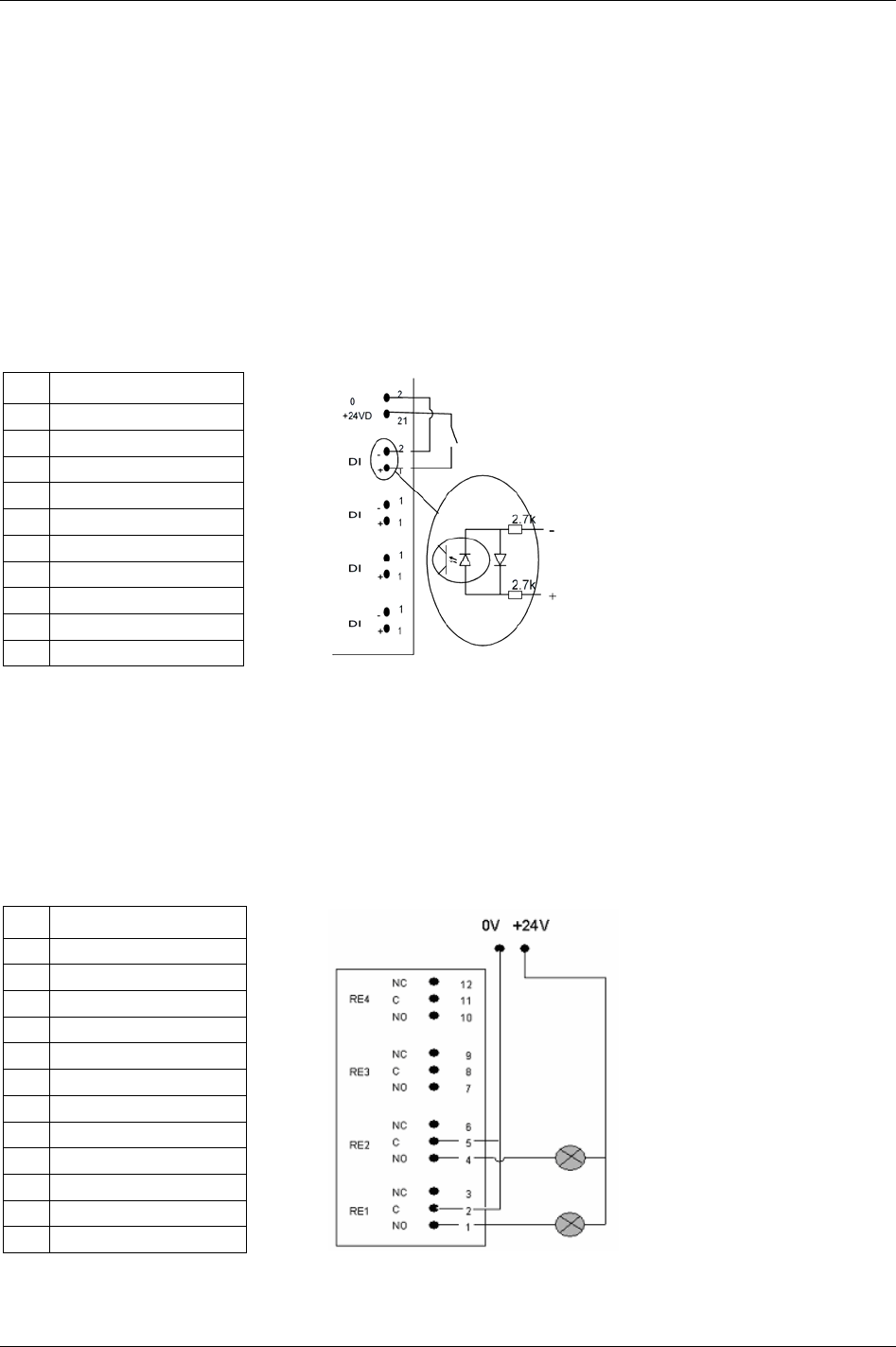
Connecting devices
18.6 Digital inputs
Connector: 10-pin detachable screw terminal. Mating connector phoenix MCVR 1.5/10 -ST- 3.81 or
compatible.
Function: Isolated optic-coupled digital input. Logical function is set in the configuration of the Power
Focus.
Electrical data: “High” input (10 - 40) VDC. Current needed to activate input is 5 mA at 24 V.
This input can be connected to run both positive and negative logic (active high or active low).
Isolated 24 VDC output. (19 V - 30 V). 1 A maximum load. This output can be used to feed external
equipment such as stack lights and buzzers. Atlas Copco I/O bus accessories are also powered from this
output.
Pin Function
13 Digital input 1 +
14 Digital input 1 -
15 Digital input 2 +
16 Digital input 2 -
17 Digital input 3 +
18 Digital input 3 -
19 Digital input 4 +
20 Digital input 4 -
21 + 24 VDC isolated
22 GND (+24VDC isolated)
18.7 Digital outputs (relays)
Connector: 12-pin detachable screw terminal. Mating connector phoenix MCVR 1.5/12-ST-3.81 or
compatible.
Function: Two ways dry contact relays, isolated outputs. Logical function is set in the configuration of the
Power Focus.
Electrical data: Max 50 V DC/AC. Switching load: min 1 mA, max 500 mA resistive loads.
Pin Function
1 Relay 1 Normally open
2 Relay 1 Common
3 Relay 1 Normally closed
4 Relay 2 Normally open
5 Relay 2 Common
6 Relay 2 Normally closed
7 Relay 3 Normally opened
8 Relay 3 Common
9 Relay 3 Normally closed
10 Relay 4 Normally opened
11 Relay 4 Common
12 Relay 4 Normally closed
9836 3123 01 215 (330)
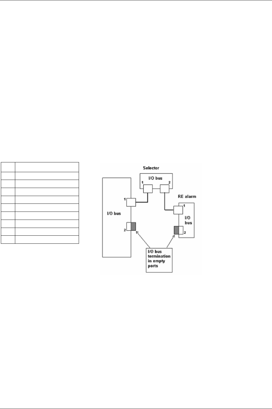
Connecting devices
18.8 I/O bus #1
Connector: 9-pin D-sub male.
Function: To connect Atlas Copco I/O bus accessories and interconnect several PF units in
synchronisation mode. I/O bus connector #1 is parallel with I/O bus connector #2.
There is a range of Power Focus accessories that connect over the proprietary Power Focus I/O bus, for
example:
Socket Selector (socket tray)
RE-Alarm
I/O Expander
Operator Panel
To have a well functioning I/O bus, always use bus connectors. All accessories and PF units are equipped
with two parallel connectors. When all cables are connected plug a lead into the empty connector. I/O bus
connectors #1 and #2 are fully parallel and can be used in any combination. If nothing is connected to the
I/O bus there is no need for anything to be plugged in.
For I/O bus Sync configuration information, see chapter
Sync.
Pin Function
1 +24 V iso.
2 Signal Low
3 0 V (+8V iso)
4 0 V (+24 V iso)
5 Not used
6 0 V (+8V iso)
7 Signal High
8 Not used
9 +8 V iso. (for I/O bus only)
18.9 I/O bus #2
Connector: 9-pin D-sub male.
Function: To connect Atlas Copco I/O bus accessories and interconnect several PF units in
synchronisation mode. I/O bus connector #2 is parallel with I/O bus connector #1.
216 (330) 9836 3123 01
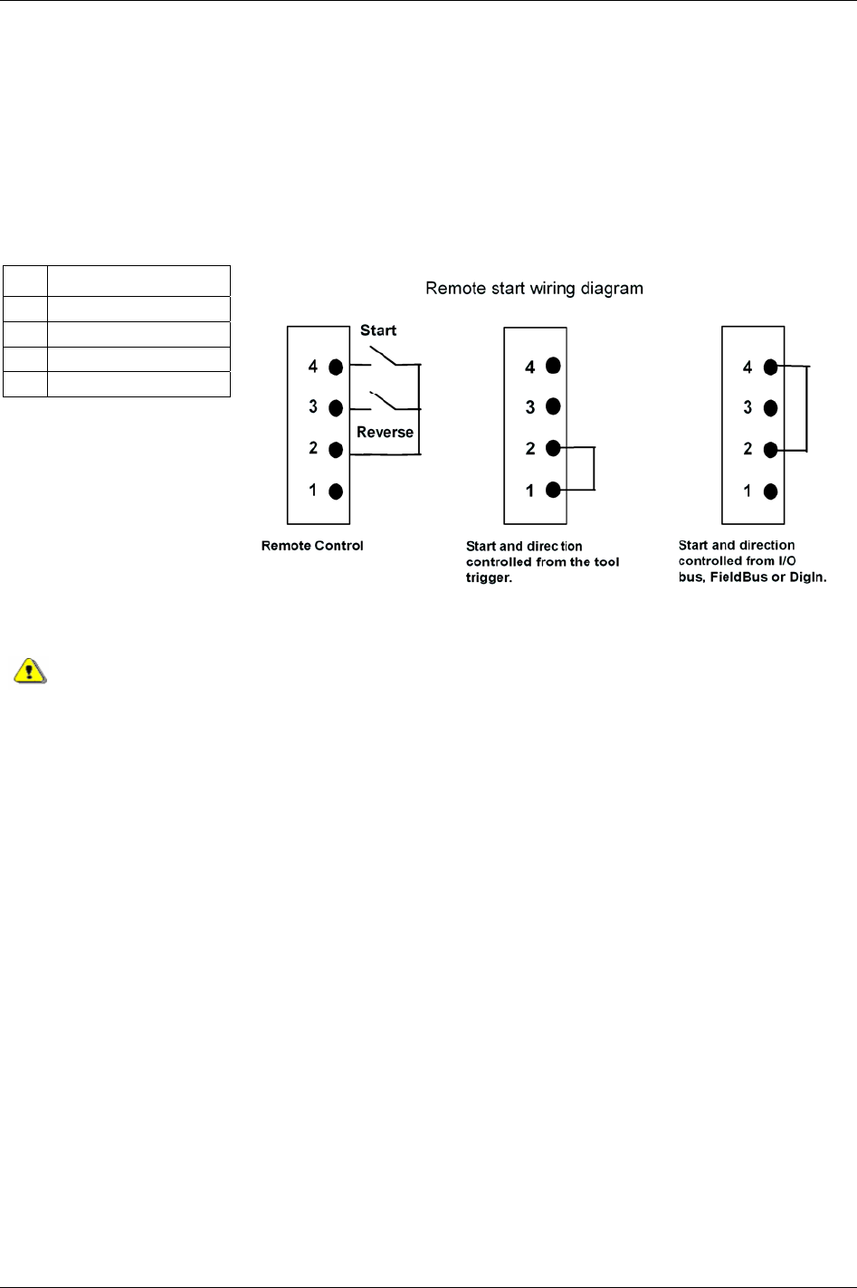
Connecting devices
18.10 Remote start connector
Connector: 4-pin detachable screw terminal. Mating connector phoenix MCVR 1.5/4-ST-3.81 or
compatible.
Function: Remote start input for use with external start switch. To run tool in reverse, first close the
reverse switch and then close the start switch. Pin 1 and 2 must be connected at power on to be able to use
the built-in tool trigger. If remote start is to be controlled from other inputs (I/O Expander, sync, Field bus
or digital input), pins 2 and 4 must be connected at power on.
Pin Function
1 Tool built-in start switch
2 Common
3 Remote reverse
4 Remote start
Make sure that the power is switched off when changing the remote start connector.
18.11 Main power connector
Connector: IEC320
Electrical data: Input voltage (90 - 120) VAC, (200 - 240) VAC, (50 - 60) Hz. Auto select of voltage input
span.
9836 3123 01 217 (330)

RBU
19 RBU
The RBU (Rapid Backup Unit) is a software key and data storage unit for the PF. The RBU unlocks
software applications available for each RBU type. It also stores a backup copy of the Power Focus
configuration. The RBU backup copy makes it possible to move functionality and configurations between
different PF units. A PF cannot be used without a RBU inserted.
There are different RBU types available; gold, silver, bronze, X and DS:
The
RBU gold unlocks the full capacity and functionality of the Power Focus. Features such as Cell
Jobs and synchronised tightenings are only available with the RBU gold.
The
RBU silver unlocks advanced Power Focus functionality such as Multistage and Job. This RBU
also enables full networking capability and the possibility to run Tensor DS Tools.
The
RBU bronze unlocks the basic Power Focus tightening functionality. It is not possible to run the PF
Graph with a RBU bronze.
The
RBU X unlocks Power Focus functionality specific to ETX tools.
The
RBU DS unlocks Power Focus functionality specific to Tensor DS tools.
RBU Gold RBU Silver RBU Bronze
Power Focus Ethernet address is 00-50-D6 -XX-YY-ZZ (from serial RBU).
Example RBU with serial number C00015767:
C00015767 = 003D97 (hexadecimal)
C00015767 = 00-50-D6-00-3D-97 (MAC address)
Cell network connection requires PF units with identical RBU types inserted.
The RBU serial number is also part of the Power Focus Ethernet MAC address.
9836 3123 01 219 (330)

RBU
220 (330) 9836 3123 01
19.1 RBU functionality
Hardware RBU Gold RBU Silver RBU Bronze RBU X RBU DS
PF Compact X X X X X
PF Graph X X X X
Capacity RBU Gold RBU Silver RBU Bronze RBU X RBU DS
Number of Psets 250 (300*) 250 (300*) 64 250 (300*) 64
Number of Jobs 99 (400*) 99 (400*) 0 99 (400*) 32
Number of tightening results 5000 (6000*) 5000 (6000*) 5000 5000 (6000*) 5000
*Possible via memory configuration, see chapter Controller.
Control strategies RBU Gold RBU Silver RBU Bronze RBU X RBU DS
Tq con X X X X
Tq con/ang mon X X X X
Ang con/tq mon X X X X
Tq con/ang con (AND) X X X X
Tq con/ang con (OR) X X X X
Rotate spindle forward X X X X X
Rotate spindle reverse X X X X X
DS-con X X X
DS-con/tq mon X X
Rev ang con X X X
Click wrench X X X X X
Home position X X
Control options RBU Gold RBU Silver RBU Bronze RBU X RBU DS
PVT mon X X X X X
PVT compensate X X X X X
PVT selftap X X X X X
Rundown angle mon X X X X X
Current monitoring X X X X
CW/CCW operation X X X X X
Functionality RBU Gold RBU Silver RBU Bronze RBU X RBU DS
Multistage X X X X
Job X X X X
Cell Job X X
Step sync X X
I/O RBU Gold RBU Silver RBU Bronze RBU X RBU DS
Programming port (RS232) X X X X X
I/O expansion X X X X X
TCP/IP X X X X
Optional Field bus card X X X X
Barcode reader port (RS232) X X X X
Networking RBU Gold RBU Silver RBU Bronze RBU X RBU DS
Cell X X X X
Net X X X X
Multicast X X X X
Tools net X X X X
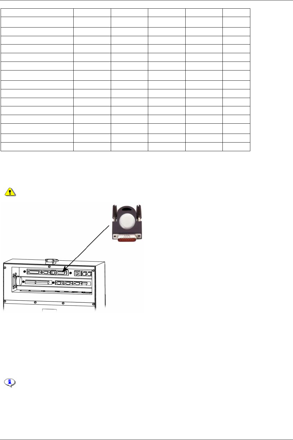
RBU
Sync X X
Tool RBU Gold RBU Silver RBU Bronze RBU X RBU DS
Tensor S X X X
Tensor ST X X X
Tensor SL X X
ETX X
Tensor DS X X X
Other RBU Gold RBU Silver RBU Bronze RBU X RBU DS
Quick programming X X X X X
Autoset X X X X X
Real time statistics X X X X
SPC (alarm) X X X
Barcode reading X X X X
Other RBU Gold RBU Silver RBU Bronze RBU X RBU DS
Configurable memory X X X
Multiple identifier X X X
19.2 Connecting the RBU
Connect the RBU to the 15-pin connector on the back panel of the Power Focus (see figure below).
Make sure that the power is switched off when connecting and disconnecting the RBU.
19.3 Start-up instructions
At start-up, the Power Focus checks for differences between the controller and RBU configurations. If an
inconsistency is detected the user is prompted to select either the controller or RBU configuration. This
makes it possible to move/copy configurations between PF units by using the RBU. The user is also given
the possibility to clear both configurations.
When changing RBU type it is only possible to load the configuration from the RBU.
Press the plus (+) or minus (-) key on the PF Compact front panel to toggle between the selections.
Confirm selection with the enter key. Press the corresponding soft key to make a selection on the PF
Graph.
9836 3123 01 221 (330)

RBU
The table describes the selections available and how to choose configuration. If the Power Focus and RBU
are incompatible for other reasons than a configuration mismatch (e.g. they have an older software
version), either the PF or the RBU is considered as NOK.
Message at start up Status
PF Compact PF Graph
Action
Power Focus and RBU
matches
No message No message No action.
Power Focus and RBU
don’t match
Clear / RBU / PF Select PF, Clear (All) or
RBU
Select “PF” for Power Focus configuration,
“RBU” for RBU configuration, or “clear (all)”
to clear Power Focus and RBU memories.
Power Focus OK
RBU NOK
PF / Clear / Stop Select PF, Clear (All) or
Stop
Select “PF” for Power Focus configuration,
“clear (All)” to clear Power Focus and RBU
memories. Otherwise select “stop”.
Power Focus NOK
RBU OK
RBU / Clear / Stop Select RBU, Clear (All)
or Stop
Select “RBU” for RBU configuration, “clear
(all)” to clear Power Focus and RBU
memories. Otherwise select “stop”.
Power Focus NOK
RBU NOK
Clear / Stop Select Clear (All) or
Stop
Select “clear (all)” to clear Power Focus and
RBU memories. Otherwise select “stop”.
Changing RBU will clear the tightening result database in Power Focus.
Selecting “Stop” will only prevent the result database from being erased if the RBU has been
changed between RBU silver and gold (provided the previous RBU is re-inserted). A change
between RBU gold and silver, or bronze and DS will clear the result database even if
selecting “Stop”. If the PF is turned on with no RBU or a PF Graph is turned on with a RBU
bronze the tightening result database will be cleared without a querying the user.
222 (330) 9836 3123 01
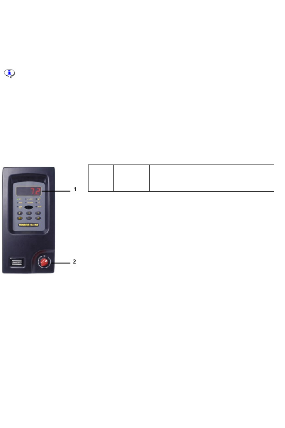
PF 3000 Compact user interface
20 PF 3000 Compact user interface
PF Compact can be programmed in ToolsTalk PF, a pre-programmed RBU or offer proper network
configuration via a PF Graph. It can also be programmed directly via the unit’s Autoset function. Except
for differences in the user interface, the PF Compact has the same functionality and capacity as the
Graph model.
For a description of connections on the PF Compact hardware description, see the
Power
Focus 3000 ASL (9836 2156 01)
.
20.1 Front panel
The front panel of the PF Compact consists of a display, indicator lights, keys and a red and white power
switch.
Number Part Description
1 Display The front panel contains a 4-digit, 7-segment display.
2 Power Switch Red and white power switch.
9836 3123 01 223 (330)

PF 3000 Compact user interface
20.1.1 Indicator lights
Indicator Description
OK The OK light indicates when the result of the tightening is
within the specified limits. The indicator remains active until
the next cycle starts.
OK flash light indicates that it is safe to disconnect the tool.
The LED goes off when the tool is disconnected.
NOK The NOK red light indicates when at least one result of the
tightening falls outside the specified limits. The light is active
until the next cycle starts.
NOK flashing red indicates that it is NOT safe to disconnect
the tool. The LED goes off after three seconds.
JOB OK The JOB OK light indicates when the result of the Job is
finished and within the specified limits. The light remains
active until the next cycle starts or when the system is reset.
n x OK The n x OK light indicates when the number of approved
tightenings corresponds to the number (batch size)
programmed into the PF. The indicator remains active until the
next cycle starts.
ALARM The ALARM indicates that an alarm message needs to be
acknowledged. The light is active until the message is cleared.
The alarm light can also flash indicating an active alarm that
does not need to be acknowledged, i.e. service indicator alarm.
PROG.
CONTROL
(padlock symbol)
If the PF is in programming mode the Programming control
light (illustrated by an open padlock) flashes green.
Programming control can be undertaken via the unit itself, via a
PF Graph or via ToolsTalk PF. A steady green light indicates
that the programming keys on the front panel are unlocked.
If the PF Compact keypad is locked, the only keys on the
controller that can be used are question mark and enter. (If the
keypad is unlocked, steady green, any key can be accessed.)
AUTOSET
(graph symbol)
The Autoset light indicates when the Autoset programming
function is active. The light goes off when Autoset is finished.
STAT The STAT light indicates when the calculated values fall
outside statistical control limits. The light remains active until
the values are within the control limits or the memory has been
reset.
224 (330) 9836 3123 01

PF 3000 Compact user interface
20.1.2 Keypad
Key Description
Plus [+] Navigates through menus on the display and increases numbers.
Minus [-] Navigates through menus on the display and decreases numbers.
Function [F] Press F (Function key) to display functions F1 - F7. To display function F1 press F once, to display function
F2 press F twice etc. Press Enter to access and edit a function. When finished, press F repeatedly to display
result mode again (or else it will take 30 seconds for the screen to automatically update).
F1 - Setting Final Target value:
“F1”/”Ft” alternates in the display. If no Pset is selected “F1”/”----“ is displayed.
Press Enter to select a new
Final target [P113] value. Change the value by pressing the +/- keys.
Press Enter to save and exit. Press F to exit (no save).
F2 - Setting Torque Tune Factor:
“F2”/”tunE” alternates in the display if the selected
Control strategy [P100] is equal to DS control. Otherwise
“F2”/”----“ is displayed.
Press Enter to access the torque tune factor. Change the value by pressing the +/– keys (range 80% - 220%,
default value 100%).
Press Enter to save and exit. Press F to exit (no save).
9836 3123 01 225 (330)

PF 3000 Compact user interface
Key Description
Function [F]
Function [F]
F3 – Motor tuning:
Press the F key three times. “F3”/”tool” alternates in the display.
Press Enter to activate the motor tuning process. The display will show the process status during progress
(1 to 7).
Press the Tool trigger to start motor tuning. The trigger must be pressed during the entire process.
Release Tool trigger or press F to abort the motor tuning process.
When the motor tuning process ends, “done” (for succeeded) or “Err” (for failed) is displayed.
After a few seconds “F3”/”tool” starts alternating on the display.
F4 - Selecting Pset:
“F4”/”Pset” alternates in the display if the
Pset select source [C200] is set to “PF keyboard”. Otherwise “F4”/”--
--“ is displayed.
Press Enter to access the available Psets. Browse existing Psets by pressing the +/- keys.
Press Enter to select a Pset and exit.
Press F to exit (no selection).
F5 - Setting Batch count:
“F5”/”batS” alternates in the display, indicating that a Pset is selected. Otherwise “F5”/”----“ is displayed.
Press Enter to access the Batch Size value (range 0 - 99). Change the batch size value by pressing the +/- keys.
Press Enter to save and exit.
Press F to exit (no save).
F6 – Disconnect tool:
“F6”/”DISC” alternates in the display.
If “safe to disconnect tool” is rolling on the display press Enter. The tool may now be disconnected.
If “Fail” is displayed, DO NOT disconnect the tool. Press F or Enter to exit.
F7 – Sync motor tuning:
Only available with RBU gold.
Press the F key seven times. “F7”/”stun” alternates in the display.
Press Enter to activate the Sync motor tuning process. The display will show two numbers simultaneously
during progress. The number to the left is the percentage of sync member that has finished motor tuning, and the
number to the right is the process status (1 to 7).
Press the Tool trigger on the sync reference to start sync motor tuning. The trigger must be pressed during the
entire process.
Release the Tool trigger or press the F key to abort the motor tuning process.
When the motor tuning process ends, “done” (for succeeded) or “Err” (for failed) is displayed. After a few
seconds “F7”/”Stun” starts alternating on the display.
F8 – Controller IP address:
Press the F key eight times. “F8”/”Stun” alternates in the display.
Press Enter to edit the first part of the IP address. Increase/decrease the number by pressing the Plus/Minus
keys.
Press Enter to confirm and edit the second part of the address. Repeat the procedure for all remaining address
parts.
Event code
Reboot needed before changes take effect [E857] will be blinking on the display when finished.
Press Enter to acknowledge the event code.
Restart the PF.
226 (330) 9836 3123 01

PF 3000 Compact user interface
9836 3123 01 227 (330)
Key Description
Autoset
(arrow target)
Press the Autoset key to enter Autoset programming mode. “Aset”/”Ft” alternates in the display and the Autoset
LED comes on.
Press Enter. Change the
Final target [P113] value (if required) by pressing the +/- keys.
Press Enter to select the Final target [P113]. “aset” is shown in the display.
Perform a number of tightenings. When Autoset is ready, the selected Pset number is displayed and the Autoset
LED goes out.
To abort Autoset press the Autoset key (exit and no save).
Question
Mark [?]
Pressing the Question mark key will display the following information:
Power Focus model:
Model type alternates with RBU type (Au = gold, Ag = silver and Br = bronze).
(“rBu” toggle with RBU type.)
Software version:
The entire program code alternates with version number.
(“rEL” with version number rolls on the display from right to left.)
Motor type:
“Type” alternates with type number, which is either 4, 7 or 9.
(“tYPE” alternatives with tool type and number, e.g. S7.)
Current Pset:
“Pset” alternates with the current Pset ID, e.g. “P27”.
Current Job:
“Job” alternates with the current Job ID, e.g. “J3”.
Enter The Enter key is used to execute selected functions and for event acknowledgement.

Tensor tools
21 Tensor tools
21.1 Tensor STB
Atlas Copco’s Tensor STB is a new generation of nutrunners.
STB is battery powered and communicates with the Power
Focus 4000 and 3100 tightening controller systems through
wireless digital communication, built on IRC (Industrial Radio
Communication) technique.
Tensor STB tools require a special Communication
kit to work with Power Focus 3100 which consists of
a, serial port adapter (access point) cable connector
(supplies the serial port adapter with power) and
serial cable.
The new digital tool-controller connection makes the tool configurable. Tensor STB tools have features
such as built in user-defined inputs and outputs.
IRC generally speaking:
2.4 GHz ISM band (2.4 to 2.485 GHz)
Frequency hopping (to avoid collision)
BT 2.0 (includes
Adaptive Frequency Hopping)
100 meters range
Atlas Copco adoptions of IRC for industrial use:
“Quiet” tool when not in use
New connection strategy
Configurable use of frequency
“Active” access point meaning faster connection
Configurable output power
Only one STB tool (BT device) per converter/AP, only STB can connect
Safe and easy paring procedure
9836 3123 01 229 (330)
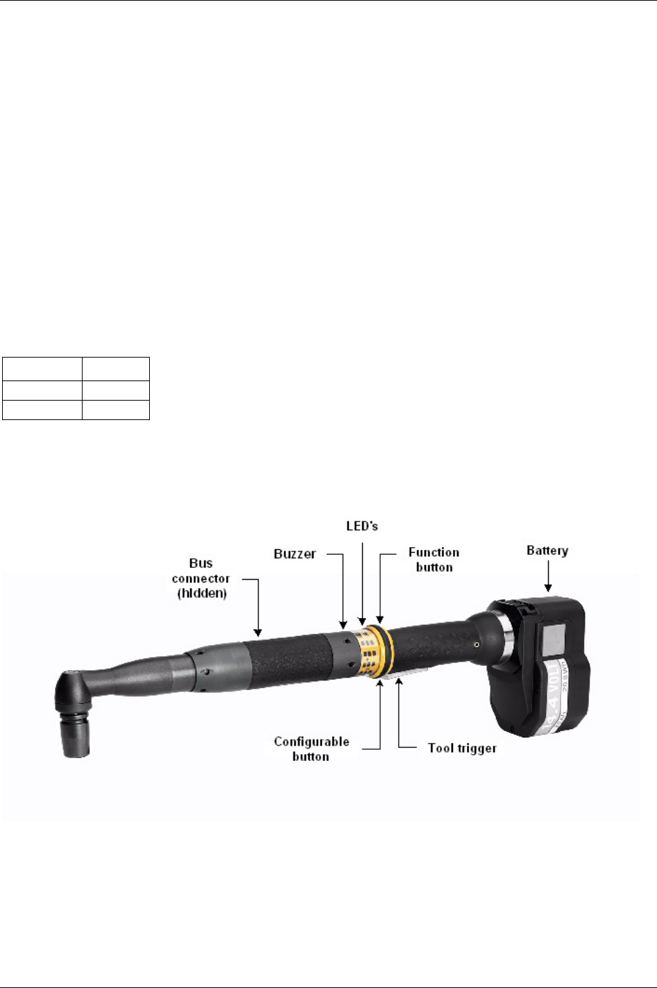
Tensor tools
21.1.1 Tool functionality
The Tensor STB tool is equipped with a buzzer and blue LED’s that can be configured as outputs to
indicate a series of events, similar to the relays on the PF.
There are also four tool LED’s for specific tasks:
Connection LED: Indicates connection to Power Focus
Battery LED: Indicates battery status (fixed light for low and flashing light for empty battery)
Batch/Job LED: Indicates Batch done
Alarm LED: A failure/event is detected
The function button, situated on the direction ring, can be configured as an input similar to the inputs on
the controller. It can generate different inputs depending on the position of the direction ring, clockwise
(CW) or counter clockwise (CCW).
Different tool batteries are used for different Tensor tool types (see table below).
Battery Tool type
NiCd 14.4 V ETV tools
NiCd 12 V ETP tools
It is possible to mount external accessories directly on the tool. Connected to the bus connector, the
accessories communicate with the controller using the same data link as the tool. The tool accessory bus
is configurable to work in different modes depending on the connected device.
230 (330) 9836 3123 01

Tensor tools
Included tightening functionality
The table below shows the tightening functionality included for the Tensor STB tool in the W7.0 release.
All necessary torque, angle, time, speed and ramp parameters are included.
Functionality Content
Tightening control strategies Torque control
Torque control / Angle monitoring
Torque control / Angle control [AND]
Torque control / Angle control [OR]
Angle control / Torque monitoring
Rotate spindle forward / reverse
Reverse angle
Tightening strategies One stage
Two stage
Quick-step
Ergoramp
Tightening options Rundown angle
Zoom step
Click wrench
Start trace from
High speed rundown
Batch Pset
Field bus
Ethernet/Serial
Lock at batch done
Max Coherent NOK’s
High speed rundown High speed rundown
Rundown speed
High speed interval
Options CW/CCW operation
Soft stop
Alarm on rehit
Alarm on Torque < Target
Alarm on Lost trigger
Alarm on End time shutoff
9836 3123 01 231 (330)

Tensor tools
232 (330) 9836 3123 01
Included miscellaneous functionality
The following miscellaneous functionality is included for the Tensor STB tool in the W7.0 release.
Auto Set
Quick programming
Job
Buzzer sound (no volume control)
Function button
Tool accessory bus
Tightening counter
Non-included tightening functionality
The following tightening functionality will NOT be included in Tensor STB W7.0.
Yield control
Home position
DS control
DS control / Torque monitoring
PF2000 compatible
Monitor end time from
PVT Self tap/monitoring/compensate
Post view torque
Current monitoring
Dynamic current monitoring
Non tightening results
Multistage
Step sync
Non-included miscellaneous functionality
The following miscellaneous functionality will NOT be included in Tensor STB W7.0.
Sensor tracking
Wear indicator
Remote start
Tool Batch LED (nxOK).
Open end tools
Safety trigger
Field bus support for new STB specific digital output.
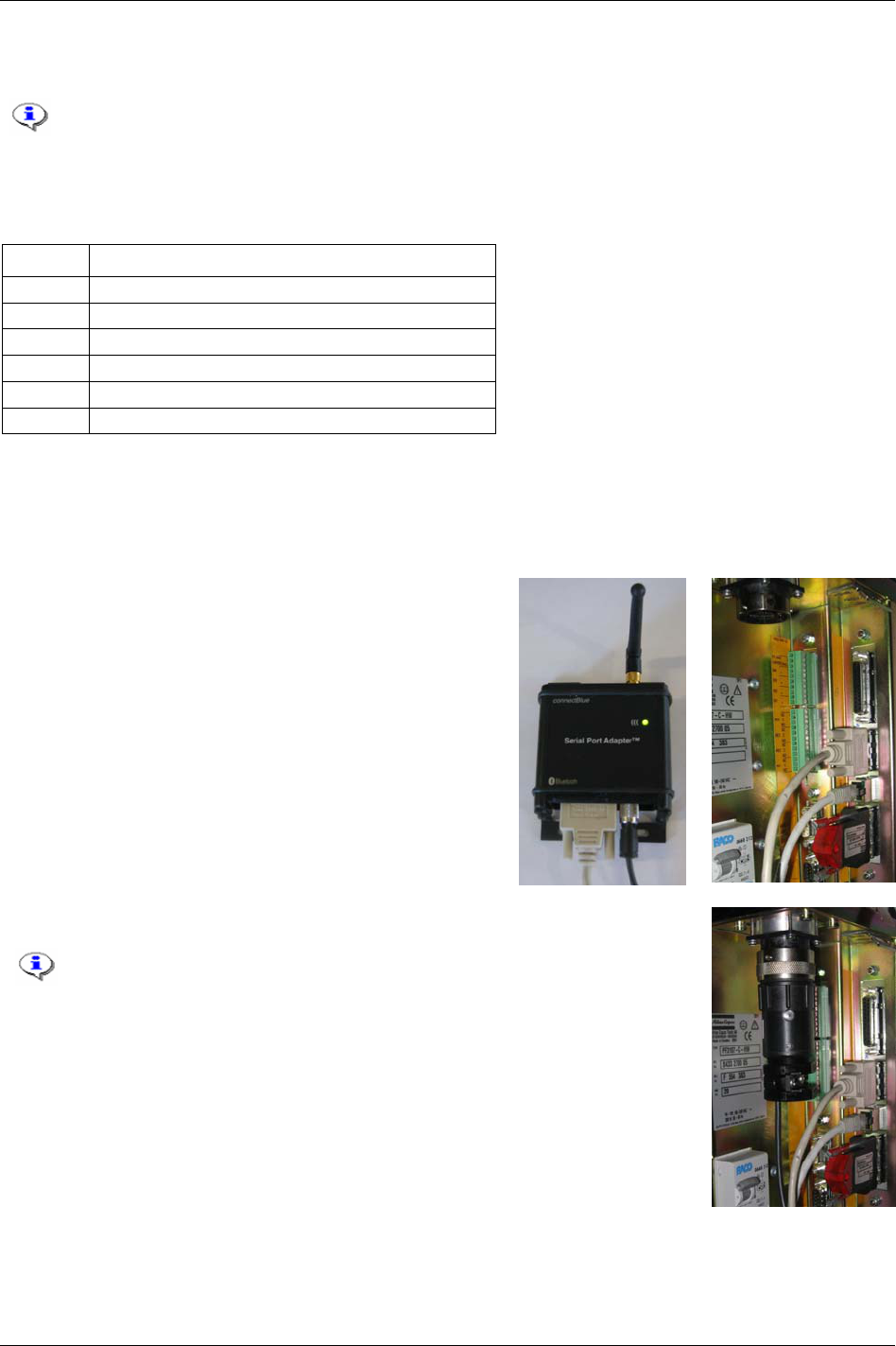
Tensor tools
21.1.2 System setup
The STB tool is running on standard Power Focus 4000 and 3100 controllers with a bronze,
silver or gold RBU inserted.
System parts
The table shows the content of a minimum Tensor STB system.
Quantity System part
1 STB tool (e.g. Tensor ETV STB31)
1 Tool battery
1 Battery charger
1 Cable connector
1 Serial Port Adapter (access point box) for Power Focus
1 Serial cable for Power Focus
Hardware setup
Setup the Power Focus system according to the local network recommendation.
Charge battery and put it on the tool.
Use a crossover cable (i.e. 4222 0546 03) to connect the
Serial Port Adapter to the Power Focus serial port 2, named
“RS232 (2)”.
Insert the cable plug into the controller.
It is NOT possible to make a serial connection between the controller
and ToolsTalk when the cable plug is inserted.
Use an Ethernet connection for ToolsTalk when the cable plug is
inserted.
Attach the small power cable to the Serial Port Adapter.
Power up the Power Focus controller.
9836 3123 01 233 (330)
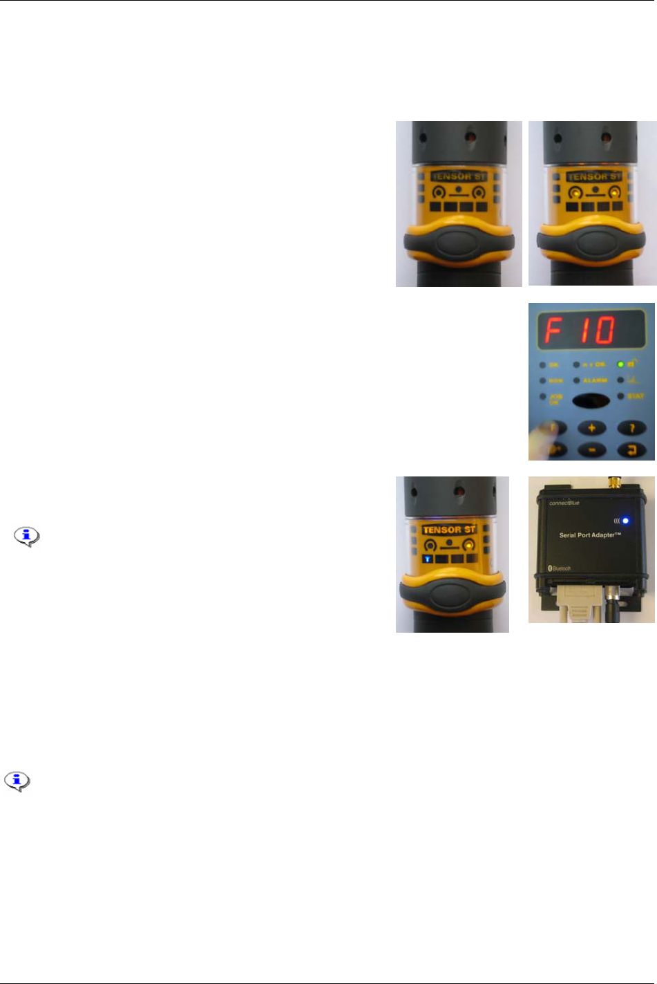
Tensor tools
The Serial Port Adapter (serial connected to Power Focus) and the tool need to be paired together in order
to establish the Bluetooth connection.
The steps below describe the pairing sequence.
Disconnect the battery from the tool.
Hold down the tool trigger while reattaching the battery.
When the tool LED’s are turned off, release the tool trigger.
When the tool LED’s are turned on again, press the tool
trigger.
When the tool LED’s are turned off once more, release the
tool trigger. Both LED’s starts to flash.
When both tool LED’s are flashing, press the F-button on the Power Focus
controller. This must be done within one minute.
Select F10 and press the return-key to confirm the selection.
Wait a few seconds for the blue connection LED’s on the tool
and the Serial Port Adapter to light up.
The paring is consistent until the tool or the Serial
Port Adapter is replaced.
It is also possible to do the Bluetooth Paring
sequence via ToolsTalk. To do this, make an
Ethernet connection with program control from
ToolsTalk.
21.1.3 Crossover Ethernet cable connection
To get started with the Tensor STB tool a ToolsTalk Ethernet connection is needed. An easy way to do
that without any available network is by using a crossover Ethernet cable directly connected to a computer
(desktop or laptop) running ToolsTalk.
The cable between the computer and the Power Focus controller must be a Crossover
Ethernet cable.
For more information, see the
Tensor STB user guide (9836 3043 01).
234 (330) 9836 3123 01
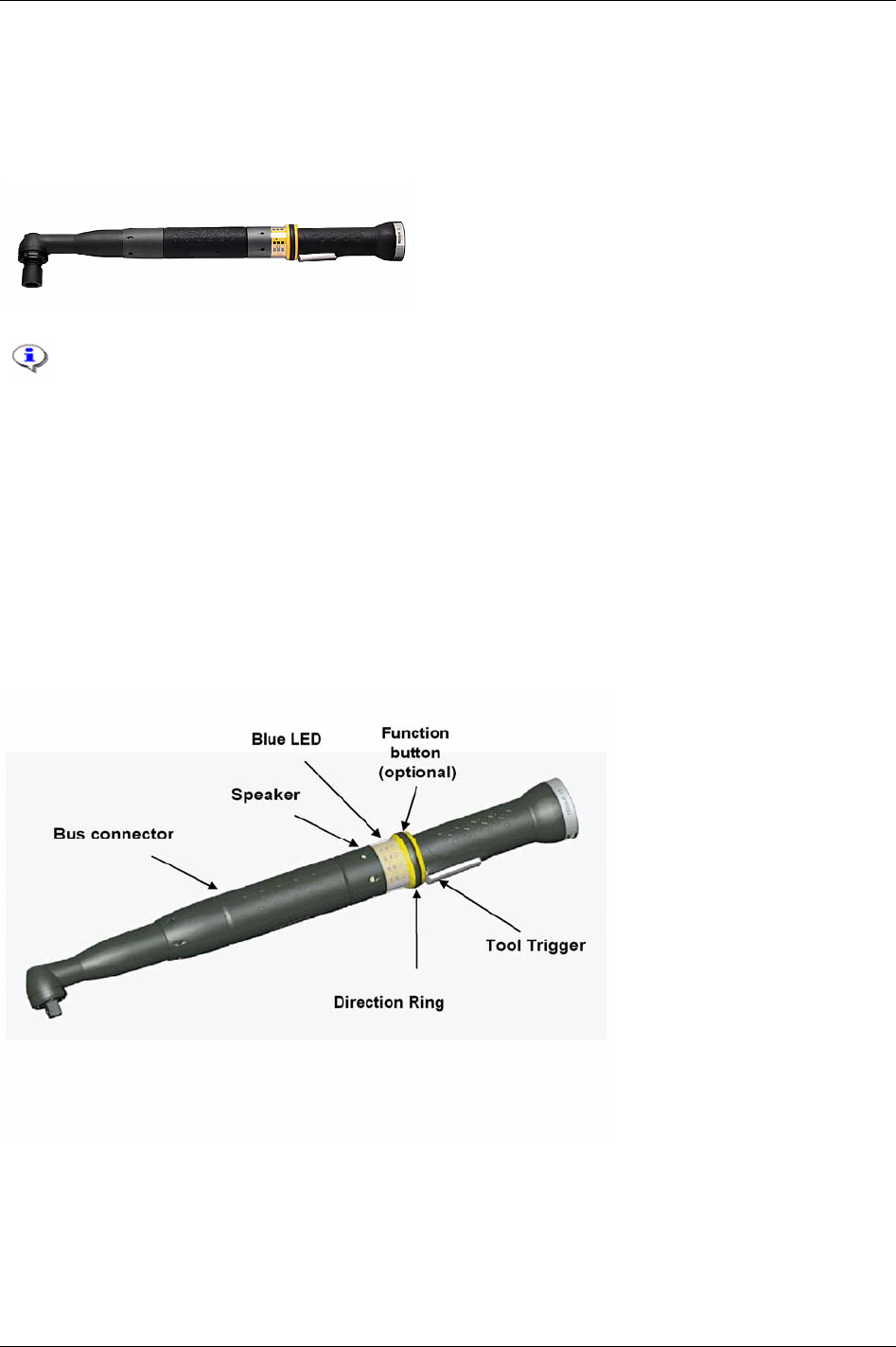
Tensor tools
21.2 Tensor ST
Tensor ST is a generation of transducerised tools. Tensor ST communicates with PF 3100 through digital
communication, which gives the benefit of new tool features and greater cable flexibility due to less leads.
Compared with a Tensor S tool, it is also lighter, has more power and provides better accessibility.
ST61-40-10
Torque range: 8 - 40 Nm (6 - 29 ft lb)
Weight: 1.4 kg (3.3 lb)
Length: 454 mm
Max speed: 1090 rpm
Configuration: Right angle
Running a Tensor ST tool requires a PF 3100 controller and a ST tool cable.
The new digital tool-controller connection makes the tool configurable. Tensor ST tools have features
such as built in user-defined inputs and outputs. Tensor ST and the digital tool-controller connection also
enable hot swapping between tools.
The Tensor ST tool is equipped with a
Speaker and an extra Blue LED. These two outputs may be
configured to indicate a series of events, similar to the relays on the controller. There is also optional to
add an extra
Function button situated on the direction ring. This button can be configured as a digital input
similar to the digital inputs on the controller. It can generate different inputs depending on the position of
the
Direction ring, clockwise (CW) or counter clockwise (CCW).
External accessories can be mounted directly on the tool. Connected to the
Bus connector, it
communicates with the controller using the same data link as the tool. The tool accessory bus is
configurable to work in different modes depending on the connected device.
9836 3123 01 235 (330)
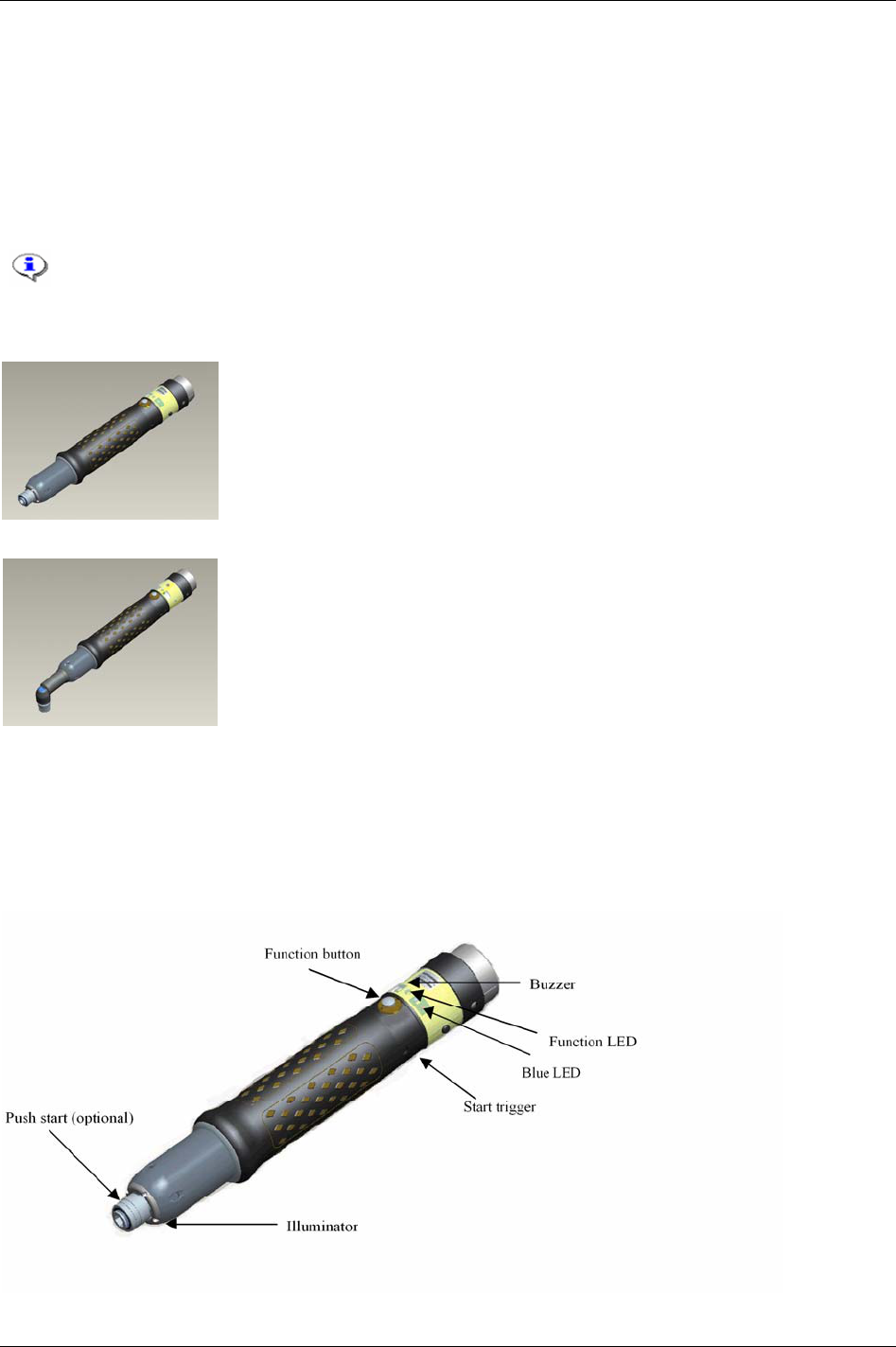
Tensor tools
21.3 Tensor SL
Tensor SL is a completely new Tensor handheld nutrunner for low torque, based on Tensor ST
technology. Like Tensor ST, digital communication it is used between tool and controller allowing
flexible cables and more functionality in the tool. The SL controller, PF 3102 is used with low voltage
SL tools. Tensor SL does, just like Tensor ST, support hot swap, see chapter
Tool.
Running Tensor SL tools requires a PF 3102 controller and a SL tool cable.
Tensor DL tools can also be connected to the PF 3102 by using a RBU DS/DL.
ETD SL21-PS-04
Torque range: 0.8 - 4 Nm (7.1 - 35.4 ft lb)
Weight: 0.7 kg
Length: 243 mm
Max speed: 1600 rpm
Configuration: Handheld
ETV SL21-07-x
Torque range: 1.5 - 7.5 Nm (13 - 66 ft lb)
Weight: 0.8 kg
Length: 245 mm
Max speed: 970 rpm
Configuration: Handheld
A Tensor SL tool is equipped with a Buzzer and an extra Blue LED. These two outputs may be configured
to indicate a series of events, similar to the relays on the controller. The
Function button may be
configured as a digital input similar to the digital inputs on the controller. It can generate different inputs
depending on the current direction according to the
Function LED. Normally the function button is
configured to change the direction of the tool.
Illuminator, a set of four LED’s in the front of the tool
provides light for the operator.
236 (330) 9836 3123 01
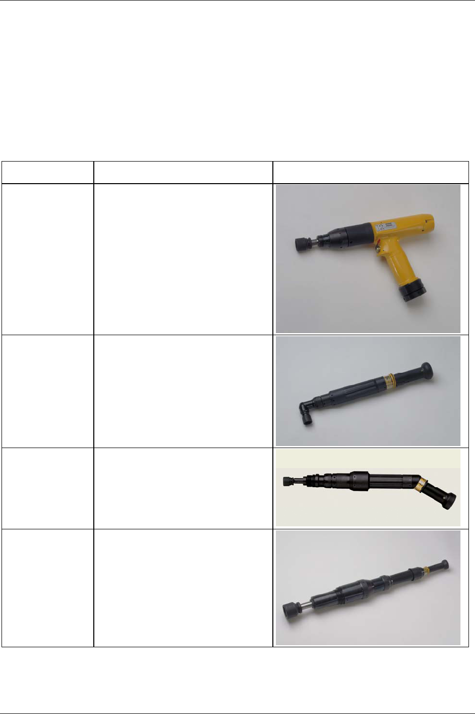
Tensor tools
21.4 Tensor S
Atlas Copco’s Tensor S tools, running on Power Focus 3000/3100/4000 controllers, are available in four
different configurations; fixture, pistol grip, straight and angle application. The three motor types are
designated S4, S7 and S9, indicating different motor outputs and speeds. The tools can be combined in
various models to meet a variety of requirements within the industry. Fixtured applications can easily be
installed and integrated with standard Atlas Copco components.
Below are some of Atlas Copco’s main products from the Tensor S electrical nutrunner range.
Name Technical data illustration
ETP S4-10-I06 Female hex/drive: 1/4”
Torque range: 3 - 12 Nm (2.8 - 8.8 ft lb)
Weight: 1.2 kg
Length: 195 mm
Max speed: 750 rpm
Configuration: Pistol Grip
ETV S7-28-10 Square drive: 3/8”
Torque range: 5 - 29 Nm (4 - 21 ft lb)
Weight: 1.6 kg
Length: 415 mm
Max speed: 1300 rpm
Configuration: Right angle
ETF S7-100-13 Telescopic drive/ square drive: 1/2”
Torque range: 20 - 110 Nm (15 - 80 ft lb)
Weight: 2.9 kg
Length: 476 mm
Max speed: 225 rpm
Configuration: Fixtured
ETD S9-1000-25 Telescopic drive / square drive: 1”
Torque range: 250 - 1000 Nm (180 - 730 ft lb)
Weight: 13.0 kg
Length: 826 mm
Max speed: 80 rpm
Configuration: Inline
9836 3123 01 237 (330)

Tensor tools
21.5 Tensor DS
The DS control strategy makes it possible to run
Tensor
DS tools on PF units.
The DS tool has no transducer. Therefore it is not possible to view torque trace when using this type of tool.
Instead of having an electrical signal from a strain gauge, the tool derives the torque from different relevant
parameters, such as voltage, speed, temperature and current. The tool is proven to achieve excellent
repeatability. However, the operating range is smaller than for a Tensor S tool, and the user might need to
adjust the torque measurement for each Pset and joint for better torque accuracy. The
DS torque tuning factor
[P245]
, adjusts the torque measurement for each combination of Pset and joint. The lack of a transducer also
decreases the number of Tensor S features available in DS control.
DS control strategy is not possible to run with Tensor S and ETX tools.
When programming the DS control strategy it is of greatest importance to have a well-
developed second stage. The fastener/socket should allow some angle rotation in the second
stage of the tightening, or else the torque may overshoot. The best way to determine this is
simply by observing the angle rotation during the second stage.
If the tool overshoots a red toggling LED will show on the tool. The criteria for overshoot are a short or a
non-existing second stage in combination with a high speed in the first stage. On the display event code
Torque measurement possibly invalid [E003] will be visible.
Torque tuning is performed either from the PF Graph user interface, ToolsTalk PF or automatically with
ACTA 3000. It allows an easy adjustment to the reference system torque values (e.g. ACTA 3000) and
compensates for tool-drive-programming and joint variations. One torque-tuning factor is stored with each
Pset. When a tool is controlled against an external torque reference for calibration, it is recommended to
calculate a new torque tuning value. There is one
Torque-tuning factor for each Pset (when changing Pset
settings a new torque tuning factor is needed):
Perform a number of tightenings with the external torque gauge connected, preferably 20 tightenings or
more to achieve a good mean value.
Calculate the mean value from the tightenings.
Factor Tuning Torque Old
Mean Measured
Target Final
Factor Tuning Torque New ×=
Enter and store the new DS torque tuning factor.
Perform another set of tightenings to control the torque.
If the torque is OK it is possible to run. If not, do the complete procedure over again.
238 (330) 9836 3123 01

Tensor tools
21.6 Tensor ETX
ETX tools are designed for fixtured applications that require spindles optimised for durability and where a
high requirement on tightening accuracy is needed. ETX is controlled by the Power Focus, just like Tensor
S and Tensor ST tools.
Below, data for a tool type ETX50-90COT.
ETX50-90COT
Torque range: 20 - 90 Nm (15 - 65 ft lb)
Max speed: 650 rpm
Weight: 5.9 kg
Length: 519 mm
Gear ratio: 18.21
Socket holder size: ½ inch
ETX offers multiple options when fixturing the front end of the tool. It can be fixtured with a sandwich
mount, for easy exchange of the socket holder, or mounted directly onto the front end. Different socket
holder lengths (0 – 200 mm), permit access to applications of parts with tight clearances. Spring travel can
also be increased from the standard 50 mm to 76 mm, simplifying fastening of longer bolts.
A memory chip in the tool holds calibration data, number of cycles, service data and model-specific data,
preventing accidental programming (as when a spindle is replaced during service).
The step Sync functionality synchronises the spindles to provide consistent clamp forces over the entire
component mating face, see chapter
Sync.
9836 3123 01 239 (330)

Tensor tools
21.7 Tools with open end
An Open end tool (or tube nut tool) is a Tensor S or
ST tool equipped with an Open end head. It is used
to tighten nuts on tubes and similar.
Open end tools alternate between tightening and positioning every second time the tool trigger is pressed.
Positioning means that the Open end head goes back to the reference position which makes it possible to
remove the tool from the tube.
It is not possible to perform loosenings with Open end tools and the direction ring can not be used to
control the rotation direction.
Before using an Open end tool, make sure that the tool head and tool body has been
assembled and configured correctly. If not, the tool can run in wrong direction and the
mechanical stop in the Open end head may be damaged.
If performing an OK tightening (green tool LED’s are on) with
OE forward positioning [C230]
set to “no” and pressing the tool trigger button, the LED’s will turn OFF and ON again.
This behaviour can only be seen on S and DS tools (not on ST and SL tools) and is normal.
The “reverse angle” and “rotate spindle forward/reverse” strategies are not applicable for
Open end tools.
It is not possible to use Open end tools in a Multistage configuration.
21.7.1 Start-up instruction
The start-up instruction is recommended every time an Open end tool connected PF is started up
(rebooted), or a hot swap of the tool has been made. The advantages of this are a faster tool rotation to the
Open end position, possibility to select
OE forward positioning [C230], and automatic generation of alarms.
Note that the operator has the possibility to perform tightenings without completing the start-up
configuration.
To do a start-up configuration, follow these steps:
Reboot the PF (or make a tool hot swap).
Press the tool trigger on the Open end tool once. The tool head rotates slowly in order to find a
reference position. The tool should now alternate between tightening and positioning when pressing
the tool trigger.
Perform ten consecutive tool trigger pressings, five tightenings and five positionings, and let the Open
end head rotate at least 360 degrees for every tightening.
After five correct tightenings and five correct positionings, the Open end head should rotate with a
faster speed meaning that correct reference point had been set.
If an Open end positioning fails (which happens if positioning is performed with a tool head fixed on the
tube), more tightenings and positionings are needed.
To perform an Open end tuning, see section
Open end tuning.
240 (330) 9836 3123 01
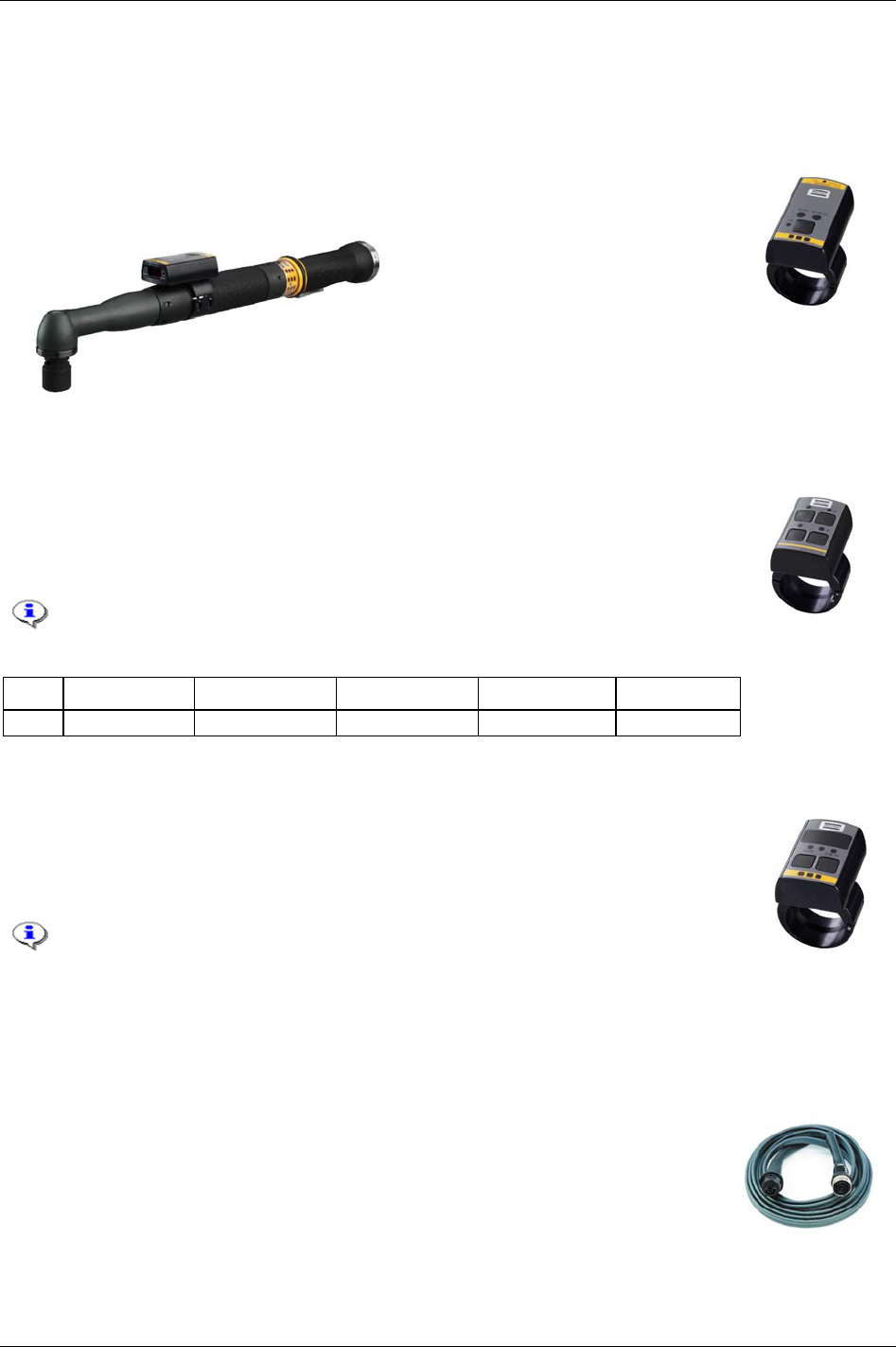
Tensor tools
21.8 Tool accessories
21.8.1 ST scanner
The ST scanner is placed on the ST tool and works as a barcode reader. For more
information about the function of identifiers see chapter
Identifier.
21.8.2 ST GPIO
GPIO (General purpose I/O) is a digital input and output connector for ST tools. The four
pins (four buttons combined with four LED’s on the GPIO device) can each be
configured as a digital input and/or digital output (see table below). That means one pin
can function as a single digital input/output, or both as a digital input and digital output.
GPIO is not available for STB tools.
Pin Function Input Output Duration Time
1 - 4 Input or output Logical function Logical function Output duration Duration time
21.8.3 ST selector
The ST selector has two different modes, mode 1 and mode 2. In Mode 1 the selector only
utilises the tool accessory bus as GPIO. This mode only supports a maximum of 15 Psets
(1-15). In
Mode 2 the selector is a true ST accessory taking full advantage of the bus
capabilities.
Mode 1 is primarily intended for use with the Power Focus world 3
software release and later. Mode 2 is recommended for users with Power
Focus world 5 software releases.
For Selector Mode configuration , see section
Tool configuration
21.8.4 ST/SL cable
ST and SL tools are used together with a cable, especially designed for the particular
tool type. The cables are equipped with memory devices used for storing information
about the tool cable, number of tightenings etc. This information can be viewed in the
diagnostic branch
9836 3123 01 241 (330)

Quick reference guide
22 Quick reference guide
Use this appendix in conjunction with chapter Digital inputs and outputs as a reference guide when
programming the Power Focus. A more general description of the tightening and control strategies
available can be found in chapter
Controller.
A joint is regarded as hard if the clamping angle, α, is small and soft if α is
large. There is no limit, but test standards define α < 30° as hard. The
dynamic effects on tightening increase dramatically if angles go down
substantially (approximately 15°).
On the following pages different control and monitoring strategies are calculated. Study the graphs and the
parameters that need to be set. Note that the graphs are presented schematically, which means that
programming results may look different compared to the graph.
9836 3123 01 243 (330)
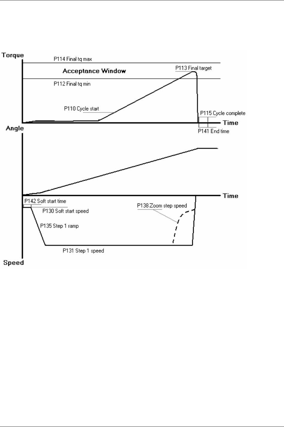
Quick reference guide
22.1 Tq con
22.1.1 One stage
244 (330) 9836 3123 01
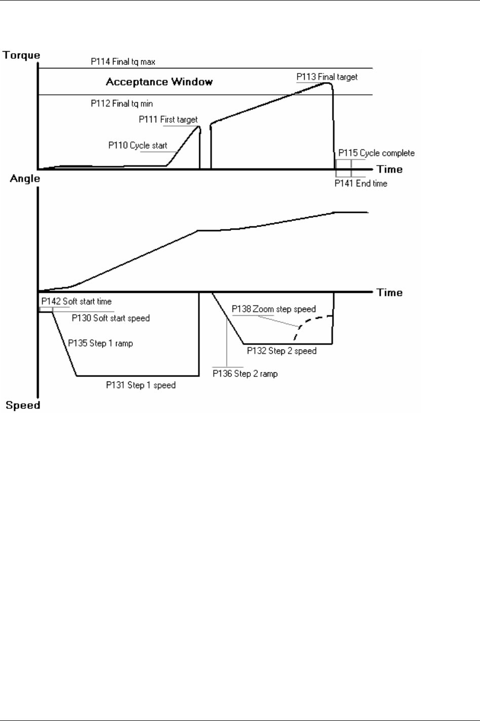
Quick reference guide
22.1.2 Two stage
9836 3123 01 245 (330)
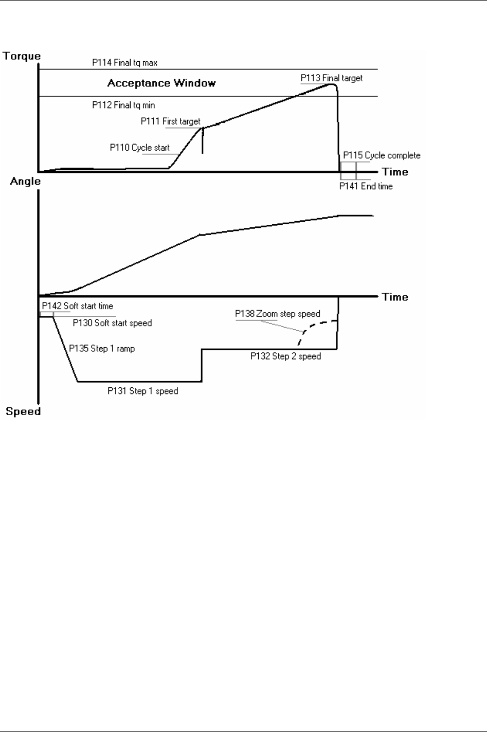
Quick reference guide
22.1.3 Quick step
246 (330) 9836 3123 01
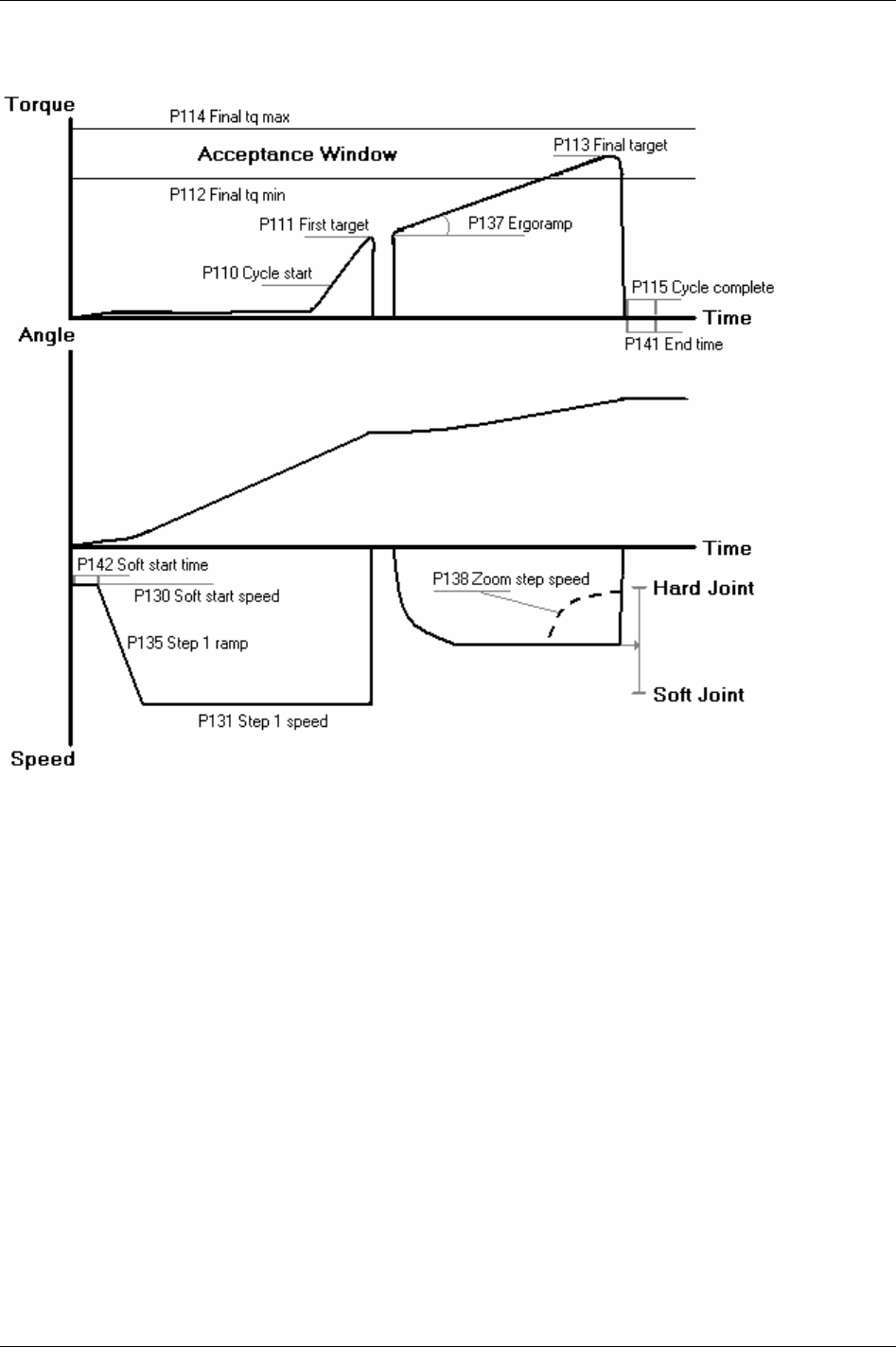
Quick reference guide
22.1.4 Ergo ramp
9836 3123 01 247 (330)
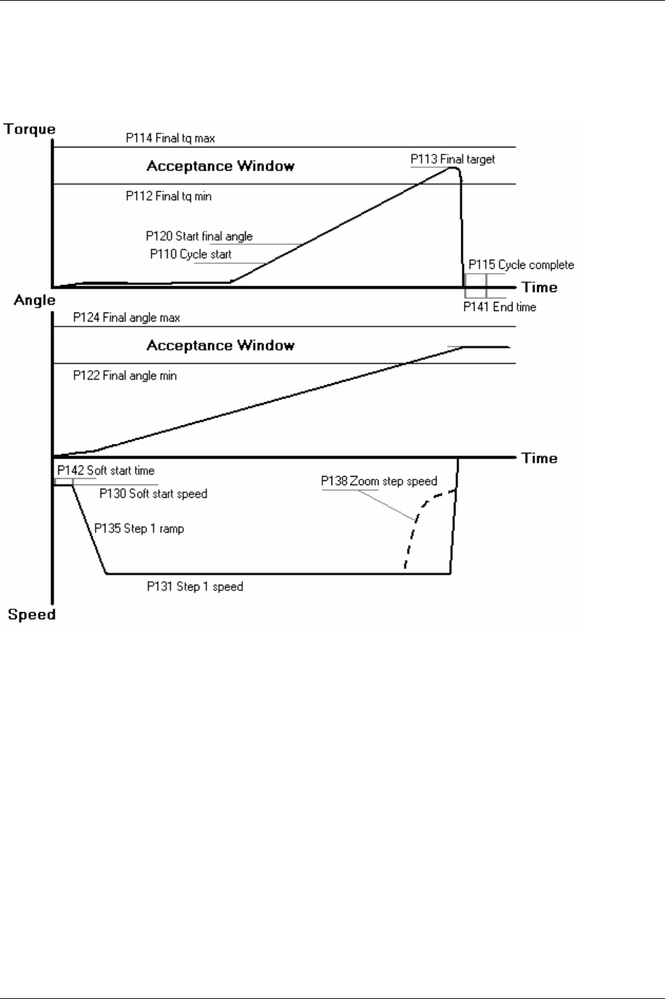
Quick reference guide
22.2 Tq con/ang mon
22.2.1 One stage
248 (330) 9836 3123 01
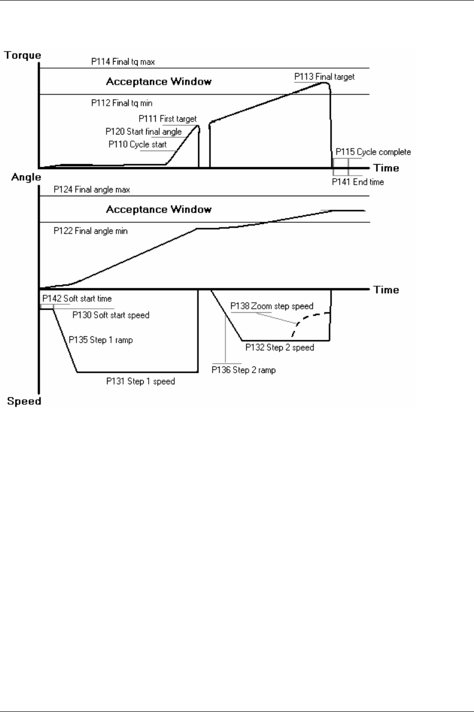
Quick reference guide
22.2.2 Two stage
9836 3123 01 249 (330)
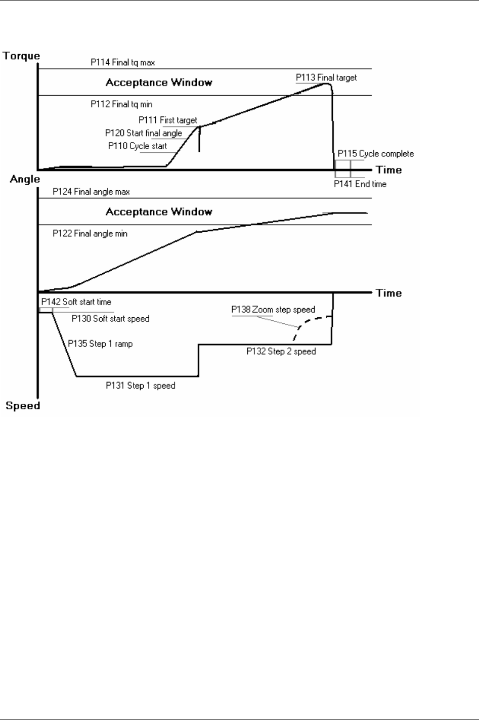
Quick reference guide
22.2.3 Quick step
250 (330) 9836 3123 01
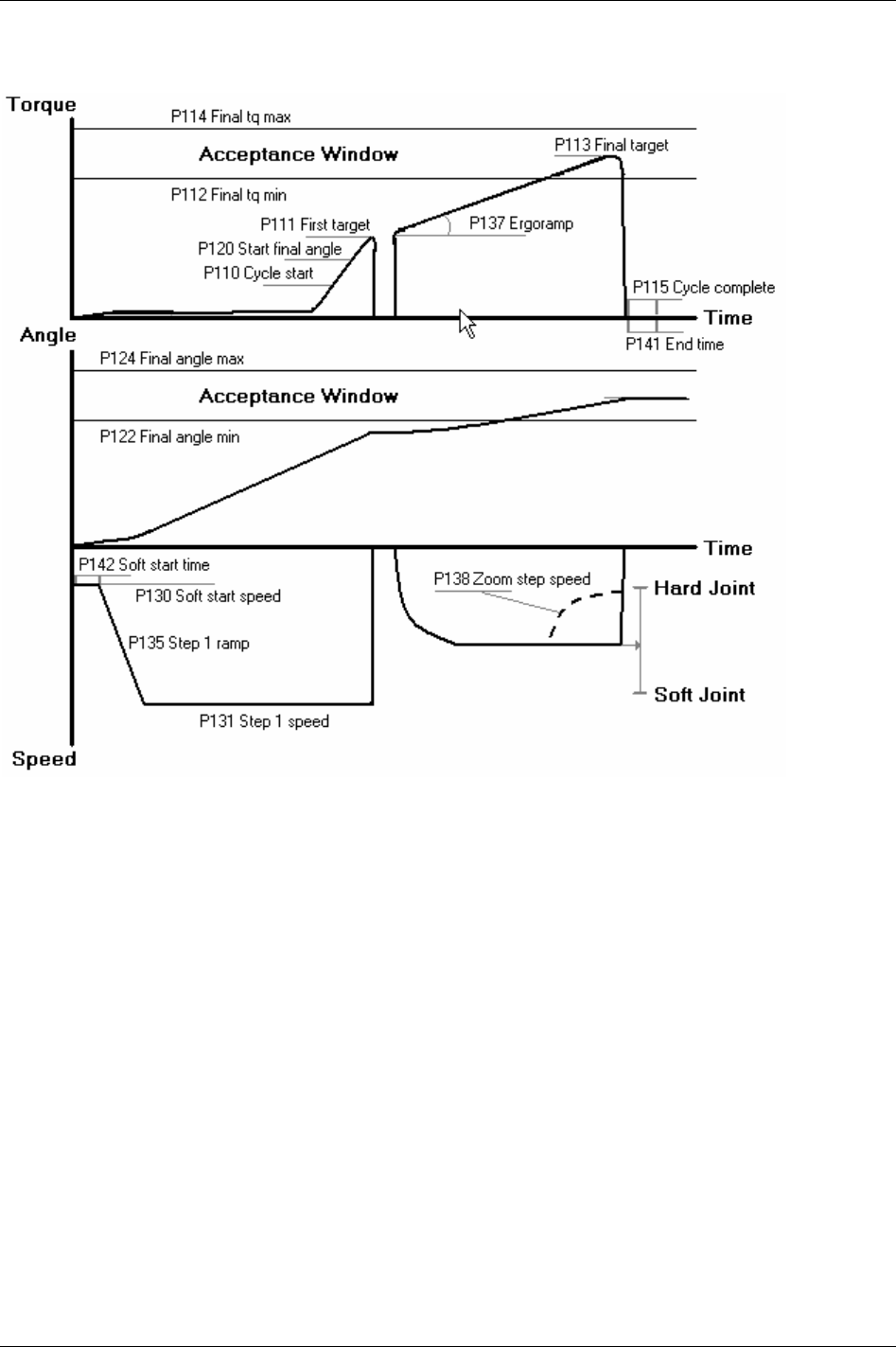
Quick reference guide
22.2.4 Ergo ramp
9836 3123 01 251 (330)
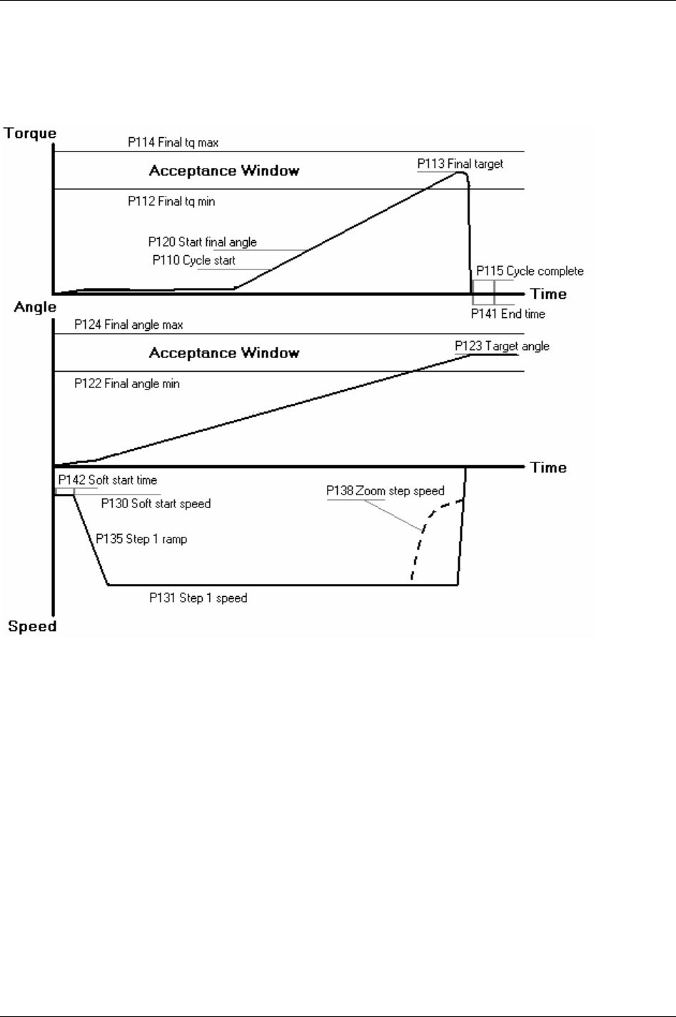
Quick reference guide
22.3 Tq con/ang con (AND)
22.3.1 One stage
252 (330) 9836 3123 01
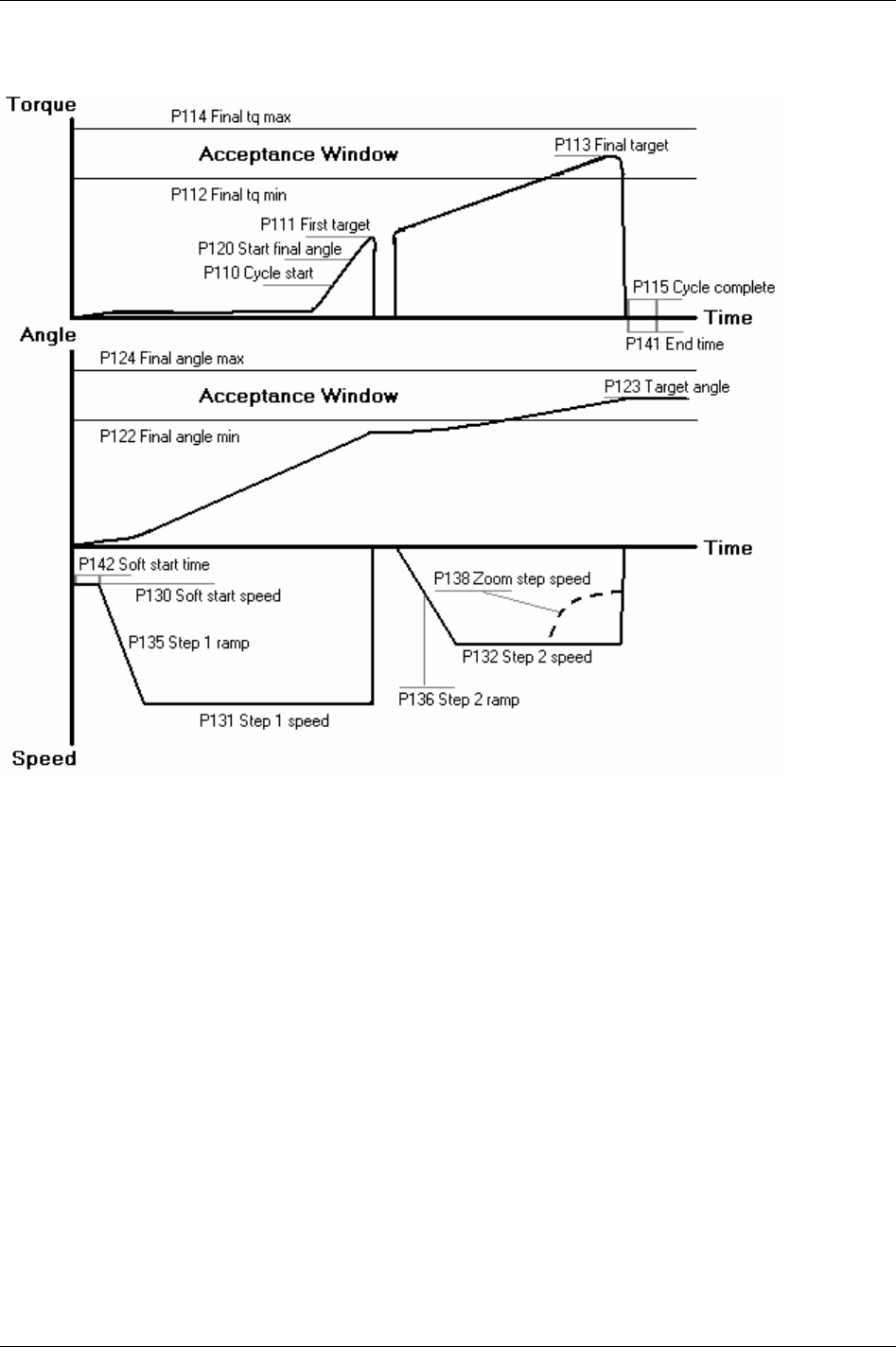
Quick reference guide
22.3.2 Two stage
9836 3123 01 253 (330)
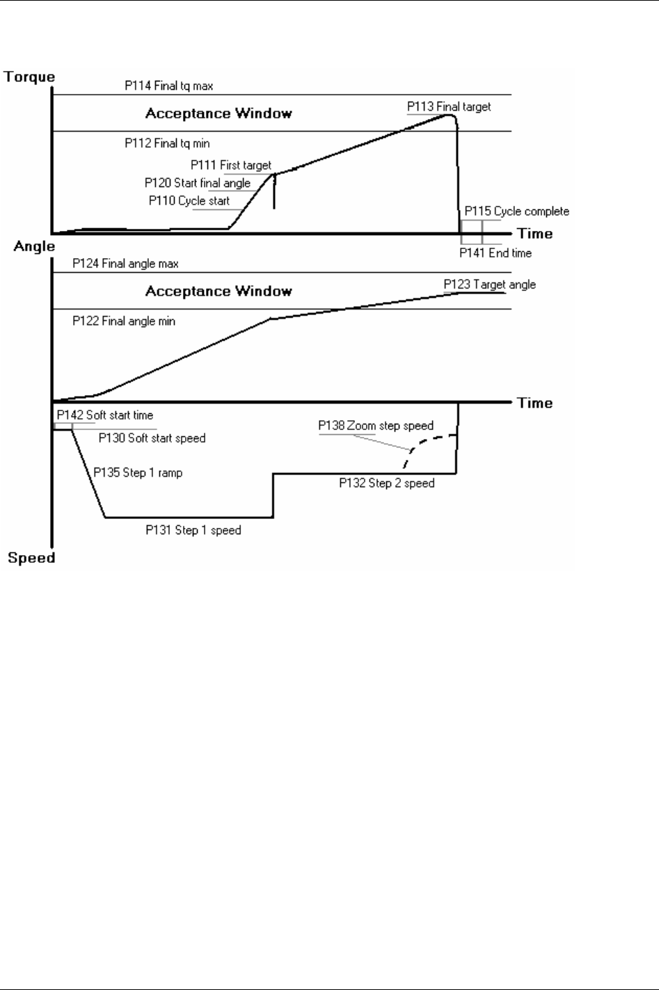
Quick reference guide
22.3.3 Quick step
254 (330) 9836 3123 01
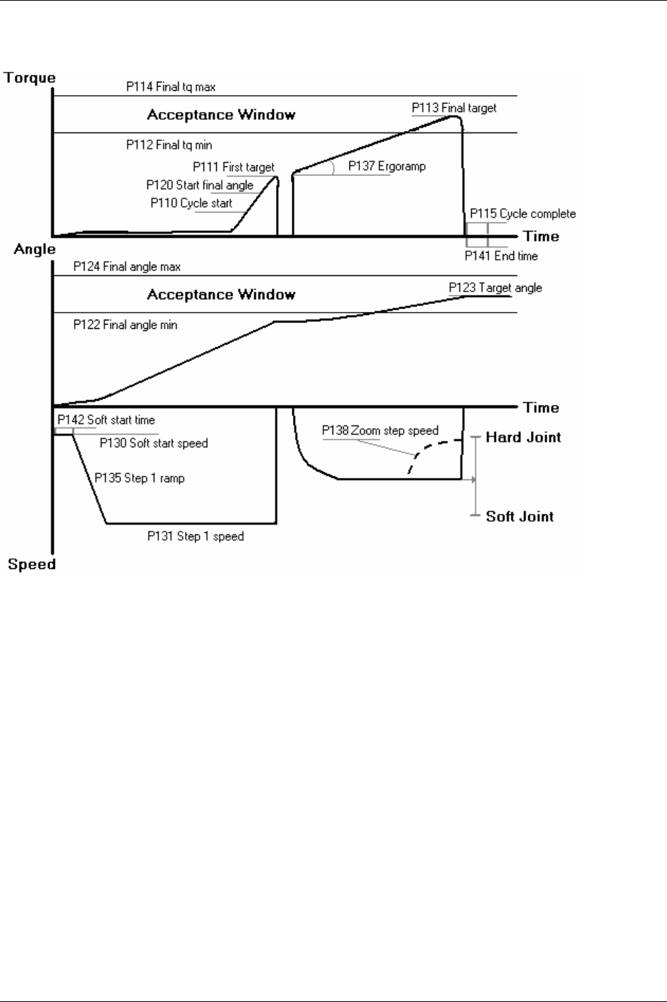
Quick reference guide
22.3.4 Ergo ramp
9836 3123 01 255 (330)

Quick reference guide
22.4 Tq con/ang con (OR)
22.4.1 One stage
256 (330) 9836 3123 01

Quick reference guide
22.4.2 Two stage
9836 3123 01 257 (330)

Quick reference guide
22.4.3 Quick step
258 (330) 9836 3123 01

Quick reference guide
22.4.4 Ergo ramp
9836 3123 01 259 (330)
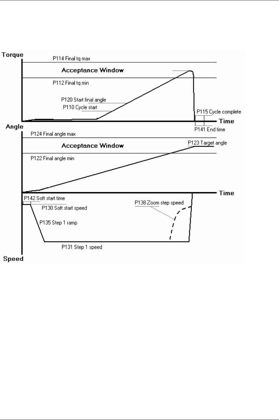
Quick reference guide
22.5 Ang con/tq mon
22.5.1 One stage
260 (330) 9836 3123 01

Quick reference guide
22.5.2 Two stage
9836 3123 01 261 (330)
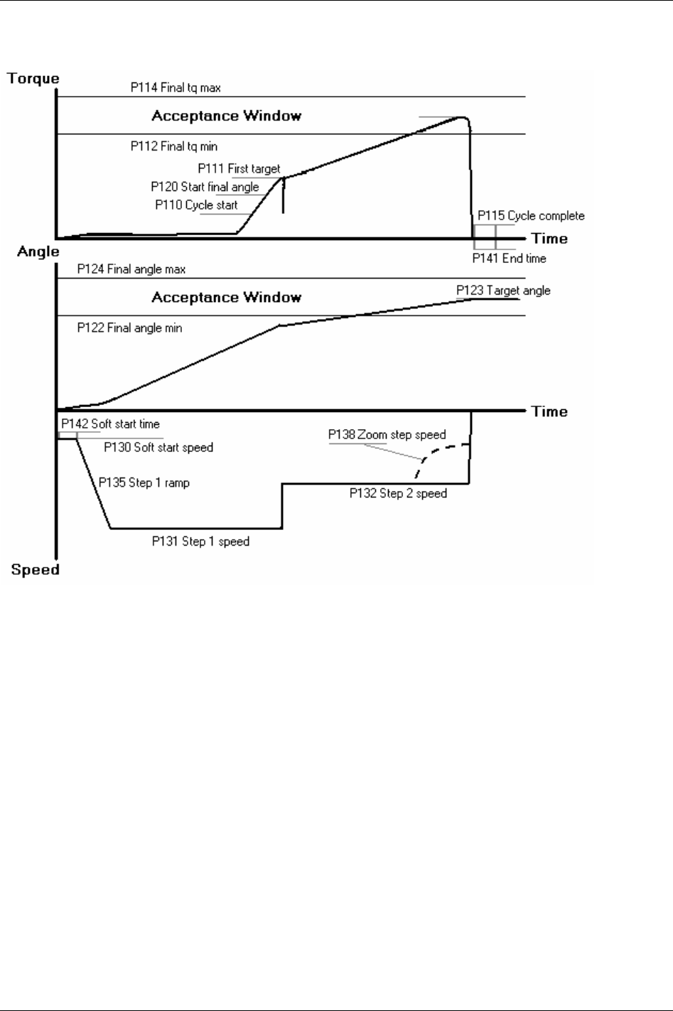
Quick reference guide
22.5.3 Quick step
262 (330) 9836 3123 01

Quick reference guide
22.5.4 Ergo ramp
9836 3123 01 263 (330)
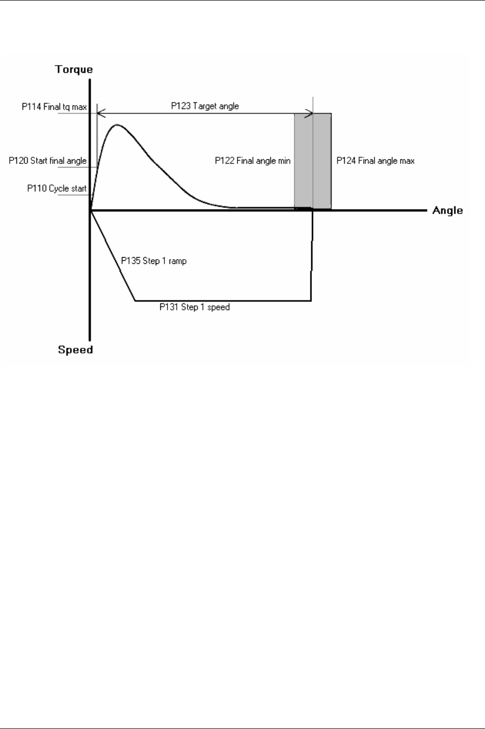
Quick reference guide
22.6 Reverse ang
264 (330) 9836 3123 01

Quick reference guide
22.7 Rotate spindle forward
9836 3123 01 265 (330)
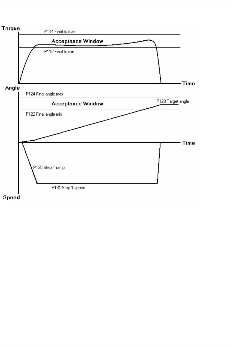
Quick reference guide
22.8 Rotate spindle reverse
266 (330) 9836 3123 01
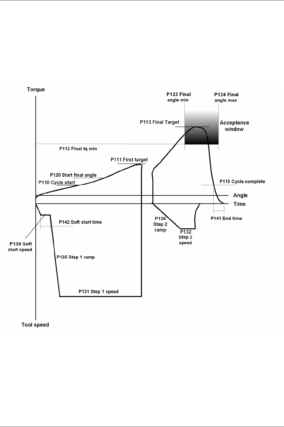
Quick reference guide
22.9 DS con
22.9.1 One stage
This strategy is not available in DS control.
22.9.2 Two stage
9836 3123 01 267 (330)
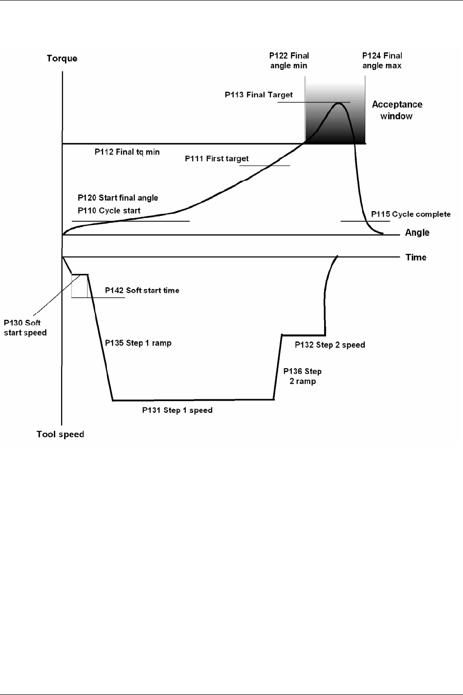
Quick reference guide
22.9.3 Quick step
268 (330) 9836 3123 01
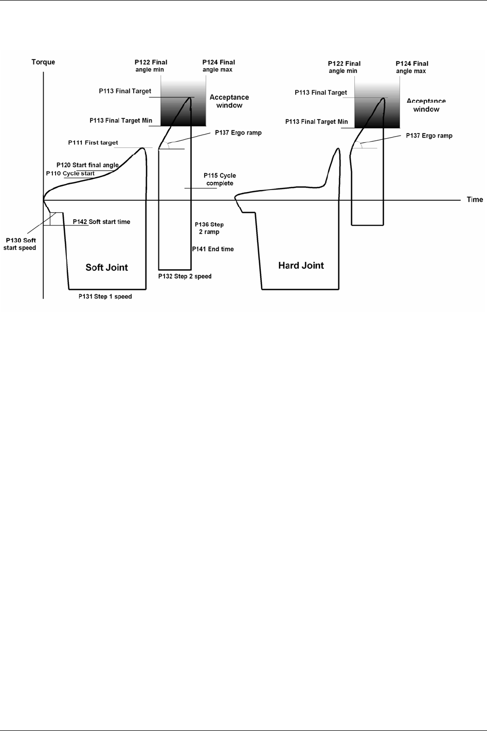
Quick reference guide
22.9.4 Ergo ramp
9836 3123 01 269 (330)

Digital inputs and outputs
9836 3123 01 271 (330)
23 Digital inputs and outputs
23.1 Digital inputs
Name Description Available
Internal I/O
I/O Expander
ST GPIO
Function button
(optional)
Abort Job Abort current Job. Job status will be Job aborted.
If
Lock at Job done [J302] is activated, the tool will be locked.
X X X X
Ack error message Acknowledgment of an event/error message. X X X X
Batch decrement Decrease the batch counter one step.
In Job, batch decrement is only possible from the Job reference and it is not
possible to decrement batch once the Job is completed.
X X X X
Batch increment Increase the batch counter one step.
Batch status is depending on Batch status at increment/bypass [C243].
X X X X
Bypass Identifier X X X X
Bypass Pset Skip the next Pset or Multistage in the running Job.
Batch status is dependent on
Batch status at increment/bypass [C243].
X X X X
Click wrench [1-4] Use in combination with the click wrench tightening strategy to confirm a
click wrench operation.
X X X X
Digout monitored
[1-4]
Monitored by digital input controlled [1-4] outputs. X X X
Disable Field bus
carried signals
When this digital input goes high following events occur:
Field bus communication is disabled.
Relay “Field bus carried signals disabled” goes high.
In ToolsTalk PF monitoring mode on Field bus “To PF” side, it is possible to
display changes in signals sent to the PF over the Field bus. (Note that the
signals have no effect on the Power Focus, since all Field bus communication
is disabled).
On the Field bus side “from PF” will all bits be reset to zero.
The traffic of “keep alive” signals continues on the Field bus. In this way no
event codes (i.e. “no connection on Field bus”) will be displayed.
All tools are enabled (presupposed that the tools were disabled from a source
over the Field bus before then).
If there is a running Job, which has been selected via the Field bus, the Job
will be aborted.
X X X X
Disable ST scanner Disable scanning from ST scanner. X X X
Disconnect tool Issue a request to disconnect the tool (hot swap for non ST/SL tools). X X
Field bus digin
[1-4]
These inputs give a direct link to Field bus. Field bus digital input numbers
must be configured in Power Focus, I/O Expander and in Field bus. Field bus
mimics the status of a digital input.
X X X
Flash tool green light Activates the tool green light (flashing at approximately 1.33 Hz). The light is
on until tightening starts. After tightening the tool light indicates status
according to result. This input is ignored during rundown.
X X X X

Digital inputs and outputs
272 (330) 9836 3123 01
Name Description Available
Internal I/O
I/O Expander
ST GPIO
Function button
(optional)
Forced CW once The tool will be forced to perform one loosening even if the ring is positioned
in CW.
After the loosening has been performed the tool will return to the current ring
position
X
Forced CW toggle The tool will be forced to perform loosening until the function has been
selected again.
After the function has been selected again the tool will return to the current
ring position.
X
Forced CCW once The tool will be forced to perform one loosening even if the ring is positioned
in CW.
After the loosening has been performed the tool will return to the current ring
position
X
Forced CCW toggle The tool will be forced to perform loosening until the function has been
selected again.
After the function has been selected again the tool will return to the current
ring position.
X
ID-card Signal input from card reader to indicate that an ID-card is inserted in the
reader.
X X X
Job off Turn off Job mode. X X X
Job select bit [0-8] Job select input when selecting Job from digital input. See table above for bit
information.
X X X
Line control alert 1 Input for a position breaker. Gives alarm if a Job with line control is not
finished.
X X X
Line control alert 2 Input for a position breaker. Gives alarm if a Job with line control is not
finished.
X X X
Line control start Input for a position breaker. Needed to start a Job with line control. X X X
Logic digin [1-10] DigIn not connected to any function but used by the Logic Operator function X X
Open protocol
commands disable
When activated all the commands received by the Power Focus via Open
Protocol are rejected.
X X X X
Off The input is not used. X X X X
Pset select bit [0-8] Pset select input when selecting Pset from digital input. The table shows the
relation between bit set and Pset ID.
Bit 2 Bit 1 Bit 0 Pset/Job ID
0 0 0 0
0 0 1 1
0 1 0 2
0 1 1 3
1 0 0 4
... ... ... ...
X X X
Pset toggle Toggle between Psets connected to one socket in a Selector.
Pset select source [C200] must be set to “Selector”.
X X X X

Digital inputs and outputs
Name Description Available
Internal I/O
I/O Expander
ST GPIO
Function button
(optional)
Remote start cont. Tool starts tightening. The tool stops if the input signal disappears (equal to a
start with tool trigger).
The position of the tool direction ring is not taken into
account. This may cause tool reaction forces in a direction
unexpected to the operator.
X
Remote start pulse Tool starts tightening if the input pulse is > 100 ms. Tool runs until target is
reached.
The position of the tool direction ring is not taken into
account. This may cause tool reaction forces in a direction
unexpected to the operator.
X
Reset all Identifier
X X X X
Reset batch Reset batch counter for current Pset. X X X X
Reset latest Identifier
X X X X
Restart Job Restart the running Job. All batch counters are reset and the Job option timers
will be restarted.
X X X X
Reset relays Resets all timer and to next tight relays (tracking event relays are not reset). X X X
Request ST scan Sending a scan request to ST scanner. The scan LED on a ST scanner will
light if a scan request is configured for the LED in ST scan configuration
(scanner source should be in digital input mode).
X X
Reset NOK counter This digital input unlocks (if locked) and resets the “max coherent not ok
tightening counter”.
X X X X
Select next Pset Select higher number Pset. X X X X
Select previous Pset Select lower number Pset. X X X X
Set home position Set the home position for Home position strategy. X X X X
Set CCW Sets direction according to input level. Low level corresponds to CW and high
level corresponds to CCW. SL drive only.
X X X
Timer enable tool Used with the function “timer enable tool” that locks the tool according to
configuration. The function unlocks the tool for a period of five seconds. Once
the period expires, the tool will be locked again. If a start attempt is made
before five seconds have passed, the tool will remain unlocked until it is
stopped or button is released (plus that a new five seconds period will be
started).
X X X X
Toggle CW/CCW Toggles direction between CW and CCW. SL drive only. X X X
Toggle CW/CCW for
next run
Changes direction and changes back automatically after one run. SL drive
only.
X X X
Tool disable n.c. Same functionality as “tool disable n.o.” above but with inverted input.
Normally closed.
X
9836 3123 01 273 (330)
Digital inputs and outputs
Name Description Available
Internal I/O
I/O Expander
ST GPIO
Function button
(optional)
Tool disable n.o. The tool will not be able to start when this input is active. If the tool rotates, it
will immediate stop when this input is active. The input is active when it is
switched on.
Normally opened.
X
Tool loosening
disable
The function is similar to “tool disable n.o.” but only for loosening.
Tightening is not affected.
X
Tool position 3
Tool start loosening Start the tool in loosening mode (for all control strategies). Tool stops if the
signal disappears.
The position of the tool direction ring is not taken into account.
This may cause tool reaction forces in a direction unexpected to
the operator.
Loosening will be performed for all strategies including reverse
ang and rotate spindle forward/reverse.
X
Tool tightening
disable
The function is similar to “tool disable n.o.” but only for tightening.
Loosening is not affected.
X
Unlock tool Will unlock any software functionality lock such as “lock on reject” or “lock
at batch OK” etc.
“Unlock tool” does not effect digital inputs like “tool disable
n.o/n.c”, “tool tightening/loosening disable” etc.
X X X X
23.2 Digital outputs (relays)
Name Description Duration Tensor
ST/SL
Time
To next tightening
Tracking
Blue LED
Sound (time duration
for all)
Alarm Follow the alarm light on the front of the PF. X X X
Batch done Goes high when batch counter is equal batch size.
Available relay timer options: Next tight, timer and tracking.
X X X X X
Battery low Tool has low battery power. X X X
Battery empty Tool battery is empty. X X X
Calibration alarm X X X
Cycle abort Set when the Power Focus reaches the cycle abort timer. X X X
Cycle complete Tightening is finished, OK or NOK. X X X X
274 (330) 9836 3123 01

Digital inputs and outputs
9836 3123 01 275 (330)
Name Description Duration Tensor
ST/SL
Time
To next tightening
Tracking
Blue LED
Sound (time duration
for all)
Cycle start Relay that is triggered at Cycle start [P110]. X X
Digin controlled [1-4] Controlled by DigIn monitored [1-4] digital input.
Dir. switch = CW Tool direction ring in CW position. X X X
Dir. switch = CCW Tool direction ring in CCW position. X X X
Effective loosening Set when the Power Focus reaches the minimum loosening
torque (defined in % of tool max torque).
X X X X
External controlled [1-10] Relay controlled by external source outside Power Focus.
Field bus carried signals
disabled
Indicates Field bus signals disable. X
Field bus offline When Field bus goes offline the light on this bit turns off. X X X
Field bus relay [1-4] Relays controlled from Field bus. X X X
Function button Function button pressed. X X X
Function button ack. Function button pressed acknowledge. X X X X
High Any result is above any of the programmed max limits. X X X X
High angle Angle result is higher than max angle limit. X X X X
High torque Torque result is higher than max torque limit. X X X X
Home position Open end tool has successfully reached its home (open) position,
or a non Open end tool has successfully completed a home
position tightening.
X X
Identifier recognised X X X X
Identifier type [1-4]
received
X X X X
Illuminator Reflects status of illuminator (tool front light). X X X
Job aborted Running Job was aborted. X X X X
Job off Will be active when Job is in off mode. X X X
Job OK Job is performed and OK. X X X X
Job NOK Job is performed and NOK X X X X
Job running A Job is selected. X X X
Line control alert 1 Line control warning. X X X X X
Line control alert 2 Line control warning. X X X X X
Line control done A Job with line control has been completed without receiving
line control alert 2.
X X X X
Line control start Line control start signal is received. X X X X
Lock at batch done Set when batch is ok and parameter Lock at batch done [P152] is
activated.
X X X
Logic relay [1-4]

Digital inputs and outputs
276 (330) 9836 3123 01
Name Description Duration Tensor
ST/SL
Time
To next tightening
Tracking
Blue LED
Sound (time duration
for all)
Loosening disabled Loosening function currently disabled. X X X
Low Any result is below any of the programmed min limits. X X X X
Low angle Angle result is lower than min angle limit. X X X X
Low torque Torque result is lower than min torque limit. X X X X
Max coherent NOK
reached
Goes high when max coherent NOK tightening counter is
reached.
X X X X X
Motor tuning disabled Motor tuning function currently disabled. X X X
N x OK Batch OK.
Only available in the Job function.
X X X X
N x NOK Batch status NOK. X X X X
New Pset selected Goes high when a new Pset is selected. Pset ID must differ from
previously selected Pset and must also differ from 0.
X X X X
New Job selected Goes high when a new Job is selected. Job ID must differ from
previously selected Job and must also differ from 0.
X X X X
Next tight
No tool connected Controller has no connection with tool. X X
NOK Any result is above or below any of the programmed max or min
limits, or some other not approved result such as rehit.
X X X X
Off Output is not used.
OK All results are within the specified limits. X X X X
Open end tuning disabled Open End tuning function currently disabled. X X X
Open protocol commands
disable
Set when the Open Protocol Commands DigIn has been
activated. In this case all the commands that the Power Focus
can receive via Open Protocol are disabled.
X X X
Open protocol connection
lost
X X X
PF ready The PF is “healthy”. No event codes need to be acknowledged. X X X
PIN code OK A PIN code entered on the RFID card reader has been validated
by the Power Focus.
X
Positioning disabled Positioning function currently disabled. X X X
Received identifier An identifier string is received. X X X X
Rehit Tightening is rehit. X X X X
Remaining batch bit [0-7] Display currently remaining Batch. Batch Counter 1 to 255 can
be displayed. “0” means that there is no remaining batch counter
(batch is completed).
X
Running Job bit [0-8] Shows selected Job. Bit pattern analogue to input Job select bits.
0 = no running Job.
X

Digital inputs and outputs
9836 3123 01 277 (330)
Name Description Duration Tensor
ST/SL
Time
To next tightening
Tracking
Blue LED
Sound (time duration
for all)
Running Pset bit [0-8] Shows selected Pset. Bit pattern analogue to input Pset select
bits.
0 = no Pset selected, tool locked.
X
Safe to disconnect tool Provides answer on disconnect tool request (regardless of origin
of request). Will be high when request to disconnect the tool is
granted and remain high until the tool is disconnected.
X
Selected Channel in Job X X
Service indicator Service level reached. On until the service indicator is reset.
Only valid if the
Service indicator [T411] is turned on.
X X X
Stat alarm Follows the stat indicator on the Power Focus’ front. Active
when the selected statistic limit or trend is outside of the
approved limits.
X X X X
Sync OK Total OK on a Sync tightening. X X X X
Sync NOK Total NOK on a Sync tightening. X X X X
Sync spindle [1-10] OK Individual OK on a Sync spindle. X X X X
Sync spindle [1-10] NOK Individual NOK on a Sync spindle. X X X X
Tightening disabled Tightening function currently disabled. X X X
Tool connected Connection established between tool and controller. X X X
Tool green light Relay follows tool green light. Also following the function flash
tool green light (no flashing).
X
Tool locked Tool is locked (tool not ready). X X X
Tool loosening Tool loosening in progress. X
Tool ready PF is ready to do tightenings. A valid Job and/or Pset selected.
The tool will start when the trigger is pressed.
X X X
Tool red light Relay follows tool red light (no flashing). X
Tool running The tool is running (CW or CCW, tightening or loosening). X
Tool start switch Relay that follows the tool start input. Follow the configured
Tool start select source [T200].
X
Tool tightening Tool tightening in progress. X
Tool yellow light Relay follows tool yellow light (no flashing). X
ToolsNet connection lost X X X
Tracking disabled Tracking function currently disabled. X X X
Wear indicator Active until service is performed (i.e. while wear alarm is
pending).
X X X

Parameter list
24 Parameter list
24.1 Pset
24.1.1 Programming
Parameter
number
Parameter name Description Default setup
P100 Control strategy Tq con: controls and monitors torque.
Tq con/ang mon: controls torque and monitors torque and angle.
Tq con/ang con (AND): controls and monitors torque and angle.
Ang con/tq mon: controls angle and monitors angle and torque.
DS con: controls a DS-type tool.
Reverse ang: controls and monitors angle when tool is used in reverse
direction.
Click wrench: a digital input signals the completion of an arbitrary activity.
No tightening is performed by Tensor tools.
Rotate spindle forward: rotates the spindle a configurable number of
degrees in the forward direction.
Rotate spindle reverse: rotates the spindle a configurable number of degrees
in the reverse direction.
Tq con/ang con (OR): controls and monitors torque and angle. Stops when
either of the criteria’s has been reached.
The “reverse angle” and “rotate spindle forward/reverse”
strategies are not applicable for Open end tools.
IF DS tool: DS
con
ELSE: Tq
con/ang mon
P101 Tightening
strategy
One stage: tightening is performed in one stage. Control is done from Cycle
start [P110]
until Final target [P113] is reached.
Two stage: tightening is performed in two stages. Control is done from
Cycle start [P110] until First target [P111]. The tool stops and then
accelerates to a lower speed and controls until
Final target [P113] is
reached.
Quick step: quick step is a variant of a two stage tightening. The difference
is that the tool speed changes directly from the higher speed to the lower
speed without stopping.
Ergo ramp: This is a two stage strategy with a constant increase in torque
during the second stage of the tightening. Gives the operator constant
reaction torque in the tool regardless of rundown speed.
Two stage
P104 Rundown angle This parameter is optional. If chosen, there are two alternatives.
From start: The rundown phase starts when the tool trigger is pressed and
continues until the torque value reaches
Rundown complete [P116].
From cycle start: The rundown phase starts when the torque level exceeds
the
Cycle start [P110] torque level and continues until Rundown complete
[P116]
is reached.
No
P105 Zoom step This parameter enables the zoom step function. Zoom step strategy
combines quick tightening with high precision and low scatter.
No
P106 PF2000
compatible
This parameter changes the characteristics of the Power Focus 3000 similar
to a Power Focus 2000. Acceleration and ramp functions are affected.
Programming of parameters is otherwise not affected. If this function is
selected, the full capacity of the tool cannot be used. The maximum torque
will not be affected.
No
P107 Click wrench no. This parameter is only used if Click wrench is chosen as Control strategy
[P100]
. It is used to connect the click wrench strategy to any one of four
defined digital input.
Click wrench 1
9836 3123 01 279 (330)

Parameter list
280 (330) 9836 3123 01
Parameter
number
Parameter name Description Default setup
P108 Start Trace from Will generate a Trace from tool start or Cycle start [P110].
Cycle start
P109 Monitor end time
from
Decides if monitoring of end time (cycle complete) will start from Cycle
start [P110]
or Rundown complete [P116].
Cycle start
[P110]
P110 Cycle start Defines the starting level for a tightening cycle. IF Control
strategy [P100]
is
set to “DS con”
or “DS con/tq
mon”:
0.1 * Tool max
torque [T102]
ELSE:
0.05 * Tool max
torque [T102]
P111 First target Defines the level at which the changeover takes place between the first and
second stage in a two stage tightening, quick step or ergo ramp.
0.25 * Tool max
torque [T102]
P112 Final tq min Defines the lower torque limit for OK tightening. 0.3 * Tool max
torque [T102]
P113 Final target Defines the desired final torque value when a torque (tq) Control strategy
[P100]
is used. The tool shuts off when the final target value is reached.
9999 Nm
P114 Final tq max Defines the upper torque limit for OK tightening. The tool shuts of if the
torque value exceeds this value.
0.5 * Tool max
torque [T102]
P115 Cycle complete This parameter indicates the torque level when the tightening cycle is
complete. When the torque falls below this level, a timer,
End time [P141],
is started.
Tightening is complete when the torque has fallen below the level for
Cycle
complete [P115]
and stayed there until End time [P141] has been reached.
0.03 *
Tool max
torque [T102]
P116 Rundown
complete
The torque level when the rundown phase is finished. (Only used if
Rundown angle [P104] or any of the PVT options are selected).
0.2 *
Tool max
torque [T102]
P118 Measure torque at Defines the torque result. Torque peak
P119 Loosening limit Defines the limit for a valid loosening. Adjustable from 0 to Tool max
torque [T102]
.
0.1 *
Tool max
torque [T102]
P120 Start final angle Angle measurement starts when the torque value exceeds this value. Start
final angle [P120]
must be selected equal to or greater than Cycle start
[P110]
.
(If a PVT option is used then it has to be greater than
Rundown complete
[P116]
.)
0.25 *
Tool max
torque [T102]
P121 Measure angle to Defines to what point the final angle shall be measured. The start point is
always
Start final angle [P120].
Tq peak: gives the angle at the highest torque value.
Angle peak: gives the highest angle value during the tightening.
Cycle complete: measures the angle at
Cycle complete [P115].
Angle peak
P122 Final angle min This parameter indicates the lower limit for final angle. If the final angle is
below this level the tightening is considered as NOK.
0 deg
P123 Target angle Indicates the target value for the angle in degrees when angle control, ang
con, is used. When this value is reached the tool is turned off.
0 deg
P124 Final angle max Defines the upper limit for the tightening angle. If the angle exceeds this
level the tightening is considered as NOK and the tool will shut off.
9999 deg
P125 Rundown angle
min
This parameter indicates the min limit value for Rundown angle [P104]. If
the angle is smaller than this value at
Rundown complete [P116], “low” is
indicated and the tool will shut off.
0 deg
P126 Rundown angle
max
This parameter indicates the max limit value for Rundown angle [P104]. If
the angle is larger than this value, “high” is indicated and the tool will shut
off.
9999 deg

Parameter list
Parameter
number
Parameter name Description Default setup
P127 Final angle max
mon
Defines the limit for the final angle max monitoring. 9999 deg
P130 Soft start speed Defines the tool speed during the soft start interval.
Allowed interval is between 1 and 30 percent of maximum tool speed.
10%
P131 Step 1 speed Defines the first step speed.
Speed is adjustable between 1 and 100 percent of max tool speed.
100%
P132 Step 2 speed Defines the second step speed.
Speed is adjustable between 1 and 40 percent of the tool max speed.
If two stage tightening is used the speed in the second step will increase
according to the
Step 2 ramp [P136] until it reaches this value. If quick step
is used the tool changes to step 2 speed directly without using a ramp.
40%
P133 Loosening speed Defines speed during loosening. The value is adjustable between 1 and 100
percent.
100%
P134 Loosening ramp Defines acceleration during loosening. The value is adjustable between 0
and 100 percent. A low percentage gives fast acceleration.
0%
P135 Step 1 ramp Defines step 1 acceleration. The value is adjustable between 0 and 100
percent. A low percentage gives fast acceleration (0% is normally used).
0%
P136 Step 2 ramp Defines step 2 acceleration. A low percentage gives fast acceleration (0-
100%).
20%
P137 Ergo ramp Defines the acceleration. The value is adjustable between 0 and 100
percent. Only used if ergo ramp is chosen as the
Tightening strategy [P101].
40%
P138 Zoom step speed Defines the speed used for zoom step strategy. The value is a percentage of
the tool’s max speed. The value is adjustable between 1 and 20 percent.
To set zoom step speed, parameter
Zoom step [P105] must be active.
10%
P141 End time This parameter defines the time Power Focus should remain active after the
torque level has dropped below
Cycle complete [P115]. The value is
adjustable between 0.1 and 5.0 seconds.
0.2 s
P142 Soft start time During this time, from the moment that the tool trigger is pressed, the
spindle rotates very slowly. This gives the operator a chance to fit the
socket on the screw. The value is adjustable between 0.0 and 5.0 seconds.
0.2 s
P143 Tool idle time Defines the tool idling time between stages in a Multistage tightening. The
value is adjustable between 0 and 32 seconds.
Accessible when parameter
Stop between stages [M205] is activated.
0.0 s
P144 Cycle abort timer If the tool does not reach its shut off point, this timer will shut it off. The
timer is activated when the tool trigger is pressed.
The value is adjustable between 0.1 and 60.0 seconds.
30 s
P150 Batch count Activates a function that measures how many times a tightening is
repeated. It must be determined from where
Batch size [P151] value should
be read, if this parameter is activated.
Options:
Off: batch count functionality is not used.
Pset: use batch size of a Pset.
Field bus: an external source decides
Batch size [P151] via Field bus.
Ethernet/serial: an external source decides
Batch size [P151] via Ethernet or
serial interface.
If batch count is used in a Job (that includes the specific Pset),
this parameter is recommended to be set to “Off”.
Off
P151 Batch size The size can be 1 - 99. To set this parameter, the Batch count [P150] must
be in active mode.
Batch size defined in Job overrides batch size defined in
Pset.
1
9836 3123 01 281 (330)

Parameter list
Parameter
number
Parameter name Description Default setup
P152 Lock at batch
done
The tool will be locked when reaching “batch done”. Batch done is reached
when the number of correct tightenings is equal to
Batch size [P151].
No
P153 Max coherent
NOK’s
Defines the number of possible not ok tightenings in a row.
Accessible when
Batch count [P150] is set to “Pset” or “off”. Scope: 1 - 10.
0 (Off)
P160 High speed
rundown
High speed rundown is a function for reducing the cycle time by running
the tool at high speed during rundown.
High speed rundown is a stage inserted between Soft start and Step 1, i.e.
the Soft start time and Soft start speed affects the number of degrees of the
rundown phase. This gives the possibility for fast tightening cycles even for
long bolts with a small angle that require a slow step-one speed to avoid
overshoots.
Off
P161 Rundown speed Rundown speed in percent. %
P162 High speed
interval
High speed rundown interval. Deg
24.1.2 Programming +
Parameter
number
Parameter
name
Description Default
setup
P200 Current
monitoring
This function is not applicable for DS tools.
Activates the current monitoring function.
The spindle torque is proportional to the motor current. By measuring motor current
a method of measurement that is independent of the torque transducer is achieved.
The torque forming current is expressed as percentage of nominal current at
Tool
max torque [T102]
. Set an acceptance window for the torque as redundant process
control via parameters
CM min [P201] and CM max [P202].
No
P201 CM min Defines min limit for OK tightening. 0.0%
P202 CM max Defines max limit for OK tightening. 150%
P210 Selftap Activates the PVT selftap function.
When the joint has a torque peak at the start of the tightening it can be
recommended to use the PVT selftap monitoring option to ensure that the tightening
gets the right characteristics. It also makes it possible to perform tightenings where
the start torque is higher than
Final target [P113] or final tq max [P114].
No
P211 Selftap interval Defines the section where measuring is performed.
Setting is performed in degrees in the interval 1 to 9999.
1
P212 No. of selftap
windows
Defines the number of windows that the Selftap interval [P211] is to be divided into.
Each window is then evaluated separately.
Mean value foundations are calculated from a number of windows to reduce the
effect of noise. Fewer number of windows mean that more samples will be grouped
together, hence one odd sample will have less impact on the calculated mean value
and vice versa. A higher
No. of selftap windows [P212] makes the monitoring more
sensitive whereas a lower number will filter more noise.
The number of windows can be chosen between 1 and 9999.
1
P213 Selftap min Indicates the lowest torque level for the interval. If the torque level falls below this
level, a low-level alarm will be generated. Range is from
Cycle complete [P115]
value to
Selftap max [P214].
Cycle
complete
[P115]
P214 Selftap max This parameter indicates the highest torque level for the interval. If the torque level
exceeds this level, a high level alarm will be generated. Range is from
Selftap min
[P213]
to Tool max torque [T102].
9999 Nm
P220 PVT
monitoring
Activates the PVT monitoring function. No
282 (330) 9836 3123 01

Parameter list
Parameter
number
Parameter
name
Description Default
setup
P221 PVT delay
interval
Defines delay before PVT monitoring [P220] starts.
Setting is performed in degrees in the interval 0 to 9999.
0 deg
P222 PVT monitor
interval
Defines the interval during which the PVT monitoring [P220] is to be performed.
Setting is performed in degrees in the interval 1 to 9999.
1 deg
P223 No. of PVT
windows
Defines the number of windows that the PVT monitor interval [P222] is to be divided
into. Each window is then evaluated separately.
Mean value foundations are calculated from a number of windows to reduce the
effect of noise. Fewer number of windows mean that more samples will be grouped
together, hence one odd sample will have less impact on the calculated mean value
and vice versa. A higher
No. of PVT windows [P223] makes the monitoring more
sensitive whereas a lower number will filter more noise.
The number of windows can be chosen between 1 and 9999.
1
P224 PVT min limit This value is evaluated against the monitor interval peak value at the end of the
interval. If the torque value falls below this limit, an alarm is generated.
Cycle
complete
[P115]
P225 PVT max limit This parameter is monitored in real time during the monitor interval and if
exceeded, an alarm is generated.
Rundown
complete
[P116]
P230 PVT comp When this option is set to “yes” a prevailing torque PVT compensate is (measured at
the interval of 20 samples preceding start of
PVT comp point [P231]) used as
reference for the torque during the actual tightening cycle.
All torque values; i.e.
Final target [P113], First target [P111] and Final
tq max [P114]
are compensated (subtracted) from the prevailing
value. Also, the results are compensated.
No
P231 PVT comp
point
The value can be set between 0 and 9999 degrees. 10 deg
P240 Tool tightening
direction
CW/CCW
Select tool rotation direction. “CW” for right hand threaded screws and “CCW” for
left hand threaded screws. To be able to start in the decided direction, turn the tool
direction ring to its correct position.
This parameter has no effect when running an Open end tool (tube
nut tool).
CW
P241 Soft stop Yes/No
The PF will ramp down the torque when target is reached. The “yes” option is
recommended.
Yes
P242 Alarm on rehit Yes/No
If selected, Power Focus will detect rehits (event code Rehit [E112]). The red tool
LED will be lit when a rehit is detected. The criteria for a rehit are a short or a non-
existent second stage in combination with a slow speed in the first stage.
No
P243 Alarm on tq <
target
Yes/No
Decides if the tightening should be approved if the final torque is lower than the
Final target [P113] but above Final torque min [P112].
No
P244 Alarm on lost
trigger
Yes/No
Power Focus will detect if the tool trigger was released before the
Final target [P113]
was reached.
No
P245 DS torque
tuning factor
Only used if “DS con” is chosen as a Control strategy [P100]. It compensates for the
error that DS measurement induces. The value can be set between 80 and 220
percent. For information how to adjusting the DS torque tuning factor, see chapter
Tensor tools.
100%
P246 Alarm on end
time shutoff
Yes/No
If end time times out before
Final target [P113] was reached then an event code will
be displayed.
No
9836 3123 01 283 (330)

Parameter list
Parameter
number
Parameter
name
Description Default
setup
P260 Torque, TC The torque threshold where the yield control is to be started.
Yield control is activated by selecting the
Control strategy [P100] to
Yield. The
Tightening strategy [P101] can be set to One stage, Two
stage or Quickstep, and yield control will always interact in the last
stage of the tightening.
Zoom step [P105] strategy ending is eliminated when yield control is
selected. An additional tightening angle can be added after the yield
point is reached by setting an angle to the Angle step [P264]
parameter.
0.0 Nm
P261 Increment Defines the angle interval between samples. 0 deg
P262 No degrees Defines the length of the angle interval in which an average of the torque values
shall be calculated.
0 deg
P263 Torque
difference
Percent of the maximum torque difference between samples which estimate the
yield point limit.
50 %
P264 Angle step Additional angle step after the yield point is reached. 0 deg
P265 NOS Parameter for Yield method 2 0 deg
P266 RNOS Parameter for Yield method 2 0 deg
P267 NNOS Parameter for Yield method 2 0 deg
P268 Torque
difference
Parameter for Yield method 2 50 %
P280 Post view
torque
Enable/disable the post view torque functionality. Only useful if torque is to be
measured during monitoring interval.
Some joints have a torque peak prior of
Rundown complete [P116]. Post view torque
function makes it possible to monitor torque values during two specified angular
intervals. The interval start is defined as angle prior to rundown complete. Torque is
then monitored for a specified angular interval. Evaluation (OK/NOK) is done when
rundown complete is reached.
Not accessible when any PVT-option is selected.
No
P281 Post view min
torque
Defines the low limit for the torque during the entire interval.
Cycle start
[P110]
P282 Post view min
monitoring
start
Start of min monitor interval. 9999
P283 Post view min
monitoring
interval
Length of min monitor interval. 1
P284 Post view max
torque
Defines the high limit for the torque during the entire interval.
Rundown
complete
[P116]
P285 Post view max
monitoring
start
Start of max monitor interval. 1
P286 Post view max
monitoring
interval
Length of max monitor interval. 1
284 (330) 9836 3123 01

Parameter list
24.1.3 Pset setup
Parameter
number
Parameter name Description Default
setup
P400 View existing Psets To view existing Psets in the current PF channel. Both numbers and logical
names will be displayed.
P401 Create new Pset To create and open a new Pset. Each Pset has a unique ID number between 1
and 250 (or up 300 with the configurable memory functionality).
P402 Name Pset Used when a selected Pset is to be named with a logical name. Up to 25
characters.
Empty
string
P403 Copy Pset Used when a source Pset is to be copied to a destination Pset.
P404 Delete Pset Used when a Pset is to be removed.
If a Pset is a part of a Job it can not be deleted.
P406 Pset updated Timestamp (date and time) for Pset latest modification. Not editable.
P407 Disable result on
ext.prot.
No result for this Pset is sent on external protocols i.e. Field bus and Open
protocol, only sent on ToolsTalk PF protocol.
P410 Delete Pset results Used when all results that belong to the current Pset are to be cleared.
P411 Delete all results Used when all Pset results are to be cleared.
24.1.4 Statistic programming
Parameter
number
Parameter
name
Description Default
setup
P500 Min valid stat tq
limit
The result must be greater than or equal to this value in order for it to be included in
the statistical calculations.
0 Nm
P501 Max valid stat tq
limit
The result must be less than or equal to this value in order for it to be included in the
statistical calculations.
9999 Nm
P502 Subgroup size Defines the subgroup size for statistical diagrams and control limits. If this
parameter is changed, the results will be recalculated.
Group size can be set between 2 and 20.
4
P503 No. of subgroups Power Focus can automatically calculate statistical control limits. In order for these
limits to be reasonable, they must be performed on a greater number of tightenings.
This parameter is used to set the number of subgroups used for these calculations.
10
P504 Subgroup
frequency
Defines which subgroups that will be used in the statistical calculations. If the
frequency is 4 then only every fifth subgroup will be used.
1
P505 Latest n values The latest number of values (1 - 100) that is used in the statistical calculations. 30
P506 SPC alarm tq With this parameter it is possible to switch on or off the torque SPC alarm function. Off
P507 SPC alarm angle With this parameter it is possible to switch on or off the angle SPC alarm function. Off
P508 SPC alarm CM With this parameter it is possible to switch on or off the current SPC monitoring
alarm function.
Off
P510 Torque X-bar
LCL
The lower control limit for mean value.
Calculated automatically or entered manually.
0 Nm
P511 Torque X-bar
UCL
The upper control limit for mean value.
Calculated automatically or entered manually.
9999 Nm
P512 Torque range
LCL
The lower control limit for range.
Calculated automatically or entered manually.
0 Nm
9836 3123 01 285 (330)

Parameter list
Parameter
number
Parameter
name
Description Default
setup
P513 Torque range
UCL
The upper control limit for range.
Calculated automatically or entered manually.
9999 Nm
P514 Torque X-bar-bar The desired mean value for calculated mean values for groups of tightenings. 0 Nm
P515 Torque range-bar The desired mean value for calculated mean ranges for groups of tightenings. 0 Nm
P520 Angle X-bar
LCL
The lower control limit for mean value.
Calculated automatically or entered manually.
0 deg
P521 Angle X-bar
UCL
The upper control limit for mean value.
Calculated automatically or entered manually.
9999 deg
P522 Angle range LCL The lower control limit for range.
Calculated automatically or entered manually.
0 deg
P523 Angle range
UCL
The upper control limit for range.
Calculated automatically or entered manually.
9999 deg
P524 Angle X-bar-bar The desired value for calculated mean values for groups of tightenings. 0 deg
P525 Angle range-bar The desired value for calculated mean ranges for groups of tightenings. 0 deg
P530 Rundown angle
X-bar LCL
The lower control limit for mean value.
Calculated automatically or entered manually.
This function is only available if parameter
Rundown angle [P104]
is selected.
0 deg
P531 Rundown angle
X-bar UCL
The upper control limit for mean value.
Calculated automatically or entered manually.
9999 deg
P532 Rundown angle
range LCL
The lower control limit for range.
Calculated automatically or entered manually.
This function is only available if parameter
Rundown angle [P104]
is selected.
0 deg
P533 Rundown angle
range UCL
The upper control limit for range.
Calculated automatically or entered manually.
This function is only available if parameter
Rundown angle [P104]
is selected.
9999 deg
P534 Rundown angle
X-bar-bar
The desired mean value for calculated mean values for groups of tightenings.
This function is only available if parameter
Rundown angle [P104]
is selected.
0 deg
P535 Rundown angle
range-bar
The desired mean value for calculated mean ranges for groups of tightenings.
This function is only available if parameter
Rundown angle [P104]
is selected.
0 deg
P540 Selftap X-bar
LCL
The lower control limit for mean value.
Calculated automatically or entered manually.
This function is only available if parameter
Selftap [P210] is
selected.
0 Nm
P541 Selftap X-bar
UCL
The upper control limit for mean value.
Calculated automatically or entered manually.
This function is only available if parameter
Selftap [P210] is
selected.
9999 Nm
286 (330) 9836 3123 01

Parameter list
Parameter
number
Parameter
name
Description Default
setup
P542 Selftap range
LCL
The lower control limit for range.
Calculated automatically or entered manually.
This function is only available if parameter
Selftap [P210] is
selected.
0 Nm
P543 Selftap range
UCL
The upper control limit for range.
Calculated automatically or entered manually.
This function is only available if parameter
Selftap [P210] is
selected.
9999 Nm
P544 Selftap X-bar-bar The desired value for calculated mean values for groups of tightenings.
This function is only available if parameter
Selftap [P210] is
selected.
0 Nm
P545 Selftap range-bar The desired value for calculated mean ranges for groups of tightenings.
This function is only available if parameter
Selftap [P210] is
selected.
0 Nm
P550 PVT X-bar LCL The lower control limit for mean value. Calculated automatically or entered
manually.
This function is only available if
PVT monitoring [P220] is
selected.
0 Nm
P551 PVT X-bar UCL The upper control limit for mean value. Calculated automatically or entered
manually.
This function is only available if
PVT monitoring [P220] is
selected.
9999 Nm
P552 PVT range LCL The lower control limit for range. Calculated automatically or entered manually.
This function is only available if
PVT monitoring [P220] is
selected.
0 Nm
P553 PVT range UCL The upper control limit for range. Calculated automatically or entered manually.
This function is only available if
PVT monitoring [P220] is
selected.
9999 Nm
P554 PVT X-bar-bar The desired value for calculated mean values for groups of tightenings.
This function is only available if
PVT monitoring [P220] is
selected.
0 Nm
P555 PVT range-bar The desired value for calculated mean ranges for groups of tightenings.
This function is only available if
PVT monitoring [P220] is
selected.
0 Nm
P560 CM (X-bar) LCL The lower control limit for mean value.
Calculated automatically or entered manually.
0%
P561 CM (X-bar) UCL The upper control limit for mean value.
Calculated automatically or entered manually.
9999%
P562 CM R LCL Defines the low limit for permitted variations in the range calculations. 0%
P563 CM R UCL Defines the high limit for permitted variations in the range calculations. 9999%
P564 CM (X bar-bar) Defines the desired CM average for all of the subgroups calculated automatically or
entered manually. (If calculated: In each subgroup the average tightened CM value
is calculated. Then an average is calculated based on all of the averages.)
0%
P565 CM (R bar) Defines the desired average of the CM variation for all of the subgroups. Calculated
automatically or entered manually. (In each subgroup the average tightened CM
variation is calculated. Then an average is calculated based on all of the averages.)
0%
9836 3123 01 287 (330)

Parameter list
24.2 Multistage
24.2.1 Setup
Parameter number Parameter name Description
M100 View existing Multistages To view all existing Multistages.
M101 Create new Multistage To create a new Multistage.
M102 Copy Multistage Used for the copying of an existing Multistage.
M103 Delete Multistage Used when a Multistage is to be deleted.
24.2.2 Multistage programming
Parameter
number
Parameter name Description Default
setup
M200 Multistage name Used when a selected Multistage should be given a name (optional).
M201 Stage list Stage list specifies the list of available Psets that can be linked
together into a Multistage. Executes the specified link list of Psets into
a Multistage.
Pset 1
M202 Batch count Activates a function that measures how many times a Multistage
tightening is repeated. It must be determined from where the batch
size value should be read, if the batch count is activated.
Options:
Off: batch count is not used.
Pset: use Psets batch size.
Field bus: An external source decides batch size via Field bus.
Ethernet/serial: an external source sets batch size via Ethernet or serial
interface.
If batch count is used in a Job (that includes the specific
Pset), this parameter is recommended to be set to “off”.
Off
M203 Batch size Specifies the number of Multistage tightenings in a batch. The range
is 0 to 99.
1
M204 Lock at batch OK The next time batch OK is reached the tool will be disabled until it is
unlocked by the operator.
No
M205 Stop between stages Provides stop between the stages in a Multistage. If enabled,
parameter
Tool idle time [P143] for each Pset will be used as input
(tightenings has an idle time between two consecutive stages).
Yes
M208 Max coherent NOK’s Defines the number of possible not ok tightenings in a row.
Accessible when parameter
Batch count [M202] is set to “Pset” or
“Off”.
Off
M210 Torque result Defines from what stage the torque result will be received.
Accessible when torque is selected as a
Control strategy [P100].
Last stage
M211 Angle result Defines from what stage the angle result will be received.
Accessible when angle is selected as a Control strategy [P100].
Last stage
M212 Rundown result Defines from what stage the rundown angle result will be received.
Accessible when parameter Rundown angle [P104] is used.
Last stage
288 (330) 9836 3123 01

Parameter list
Parameter
number
Parameter name Description Default
setup
M213 PVT Selftap result Defines from what stage the PVT selftap result will be received.
Accessible when
Selftap [P210] is activated.
Last stage
M214 PVT mon. result Defines from what stage the PVT mon. result will be received.
Accessible when PVT monitoring [P220] is activated.
Last stage
M215 CM result Defines from what stage the current monitoring result will be
received.
Accessible when
Current monitoring [P200] is activated.
Last stage
M216 Trace Defines the point from what stage the graph results (Trace diagram)
will be received.
Last stage
M217 Post view torque result Defines from what stage the graph will be received.
Accessible when
Post view torque [P280] is activated.
Last stage
M220 Min valid stat tq limit >=Cycle start, < Max valid stat tq limit
The result must be greater than or equal to this value to be included in
the statistical calculations.
Not accessible when a DS strategy or reverse is selected (see
Control
strategy [P100]
).
Results are only stored in the Multistage, not in the
individual Pset.
Cycle start
[P110]
M221 Max valid stat tq limit >Min valid stat tq limit, <=tool max torque
The result must be less than or equal to this value to be included in the
statistical calculations.
Not accessible when a DS strategy or reverse is selected (see
Control
strategy [P100]
).
Results are only stored in the Multistage, not in the
individual Pset.
Tool max
torque
[T102]
M222 Subgroup size 2 - 20
Defines the size of the subgroup that forms the basis for the statistical
calculations. If this parameter is changed, all statistics have to be
recalculated or deleted.
Not accessible when a DS strategy or reverse is selected (see
Control
strategy [P100]
).
Results are only stored in the Multistage, not in the
individual Pset.
4
M223 No. of subgroups 1 - 7500
Power Focus calculates control limits on request. For these limits to
be relevant they must be based on a large number of data, at least 100.
This parameter defines the number of subgroups to be used in the
statistical calculations. If this parameter is changed, all the results
have to be recalculated.
Not accessible when a DS strategy or reverse is selected (see
Control
strategy [P100]
).
10
M224 Subgroup frequency 1 – 7500
This parameter indicates the number of subgroups that are disregarded
between every stored subgroup.
Not accessible when a DS strategy or reverse is selected (see
Control
strategy [P100]
).
1
M225 Latest n values 1 – 100
The number of tightening values which are included in the latest
statistical calculations. Not accessible when a DS strategy or reverse
is selected (see
Control strategy [P100]).
30
9836 3123 01 289 (330)

Parameter list
290 (330) 9836 3123 01
Parameter
number
Parameter name Description Default
setup
M226 SPC alarm tq This parameter switches the torque SPC alarm function on or off.
Not accessible when a DS strategy or reverse is selected (see
Control
strategy [P100]
).
Off
M227 SPC alarm angle This parameter switches the angle SPC alarm function on or off.
Not accessible when a DS strategy or reverse is selected (see
Control
strategy [P100]
).
Off
M228 SPC alarm CM This parameter switches the current monitoring SPC alarm function
on or off.
Accessible when
Current monitoring [P200] is activated.
Off
24.3 Job
24.3.1 Setup
Parameter
number
Parameter name Description Default
setup
J100 View existing Jobs To view existing Jobs in the current PF channel. Both numbers and logical
names will be displayed.
J101 Create new Job Create and open a new Job.
Each Job has a unique ID number between 1 and 99 (or up 400 with the
configurable memory function). Combining selected Psets/Multistages creates
a Job.
The new Job contains default values on all parameters.
1
J102 Name Job The name of the Job helps the operator to identify the different Jobs
(maximum 25 characters).
None
J103 Copy Job Power Focus offers the possibility to copy the properties of an already
existing Job to another Job. If the target Job has not already been created it
will be created automatically. The source Job keeps its Job ID and the target
Job gets a new Job ID.
J104 Delete Job This function deletes an already existing Job from the Power Focus memory
and the RBU. A running Job will be considered as aborted before it is deleted.

Parameter list
24.3.2 Programming
Parameter
number
Parameter name Description Default
setup
J300 Job list The Job list specifies the Psets and Multistages that can be included in
the Job. The total number of Psets/Multistages in one Job can not exceed
30.
This parameter contains:
PF channel: Power Focus channel ID that the selected Pset and
Multistage belongs to.
Pset/Ms (Event): identification number of Psets/Multistages included in
the Job. The Psets/Multistages specified in the Job must be predefined,
and they can be included in more than one Job. Same Pset/Multistage
can be used several times in a Job.
Pset name: name of the selected Psets/Multistages. (Pset name is not
visible in Job list on PF Graph).
Auto select: yes = auto select, no = manually select.
With auto select the Job functionality automatically chooses the next
Pset. With a manually selected Pset/Multistage the operator must
manually choose the next Pset.
This function is only available for forced order Jobs.
It is not possible to use the auto select functionality for
free order Jobs (see parameter
Job order type [J301]).
A Job has override privileges, in comparison to a single
Pset/Multistage, on a selected possible number of NOT
OK tightenings.
Batch size: A batch size should be specified for each Pset or Multistage
in a Job. The batch size specifies the number of tightenings to be
performed for each Pset or Multistage. Maximum batch size is 99. It is
possible to define free running Psets/Multistages by setting batch size to
0. In this case the bypass function must be used to be able to continue
the selected Job.
Max coherent Not OK tightenings (NOK’s): Max coherent Not OK
tightenings (NOK’s) are a selectable possible number of Not OK
tightenings for each Pset/Multistage in a Job. (This function is also
available for each single Pset/Multistage, see parameter
Max coherent
NOK’s [P153]
).
The tool will be locked (for both tightening and loosening) when
number of possible not OK tightenings is reached for each batch.
When the tool is locked due to possible not OK tightenings the only
ways to unlock the tool are:
Reset counter for performed not OK tightening via a digital input.
Select abort Job (in case the selected Job shall not lock the tool).
Select Job off.
J301 Job order type A Job must be defined as forced order Job, free order Job or free and
forced order Job.
Free order: offers the operator to perform Psets/Multistages in any order.
The Job members work independently from each other. In a Cell Job
with free order, all Job members are able to perform tightenings at the
same time.
Forced order: Psets/Multistages must be performed in the order specified
in the Job list. One Job member at a time performs a tightening while the
other Job members are locked.
Free and forced order: allows the operator to perform Psets/Multistages
in the same PF channel as the order defined Job, but the operator is free
to perform tightening from any channel in the Job.
Forced
9836 3123 01 291 (330)

Parameter list
Parameter
number
Parameter name Description Default
setup
J302 Lock at Job done Yes: tools of the Job members will be disabled during a Job except the
member who performs tightening according to the Job list. After a Job is
completed or aborted, tools of all Job members will be disabled for both
tightening and loosening. The tool remains locked until a new Job is
selected or the tool is enabled again.
No: the tool will be enabled for all Job members after the Job is
completed. For those Job members who are not involved in the Job the
tool will be enabled also while the Job is in progress.
Yes
J303 Tool loosening This parameter controls the tool loosening functionality during a running
Job.
Enable: tool loosening functionality is unlocked during a running Job.
Tool loosening is enabled for all Job members.
Disable: tool loosening functionality will be locked during a running
Job.
Enable only on NOK tightening: The tool loosening is disabled during a
Job but it will be enabled when a NOK tightening is performed.
Enable
J304 Repeat Job After a Job is completed, the Job will be automatically restarted. To turn
off this feature the Job must be aborted, deleted or the Job off mode
must be selected.
No
J310 Increase batch at
tightening
OK: Specifies that only accepted tightenings will be considered
performed and counted.
OK+NOK: Specifies that also not accepted tightenings will be
considered performed and counted.
This will also have directly effect on the batch status,
which will be NOK (nxNOK when not accepted tightening
is performed and counted in a Job).
OK
J311 Batch status at
increment/bypass
OK: The batch status will be OK at batch Increment or bypass event.
The nxOK LED on PF Graph or PF Compact will light.
NOK: The batch status will be NOK (nxNOK) at batch increment or
bypass event. The nxNOK LED will light.
NOK
J312 Decrement batch at
OK loosening
Decrement batch at OK loosening makes it possible to redo the latest
made tightening/increment in a Job. The batch counter of the Pset or
Multistage is decreased with one step. It is not possible to go back one
step after the Job has been completed.
If ”batch counter type” is set to OK and last tightening was
a NOK tightening, an OK loosening will not decrease the
batch counter.
When the control strategy “Ds con” is implemented and
this parameter is set to “yes”, the batch does not decrement
after an OK loosening.
No
J320 Max time to start Job This parameter defines the time limit, from when the Job is running to
when the first tightening is started or batch increment/bypass is
performed. If the time limit is exceeded the Job will be aborted. The
timer restarts if a Job is reselected.
Allowed values are between 1 - 9999 seconds. Value 0 (seconds)
deactivates this function.
0
J321 Max time to
complete Job
This parameter defines time limit, from Job is up running to the last
tightening in the Job is started. If the time limit is exceeded the Job will
be aborted.
Allowed values are between 1 - 9999 seconds. Value 0 (seconds)
deactivates this function.
0
292 (330) 9836 3123 01

Parameter list
9836 3123 01 293 (330)
Parameter
number
Parameter name Description Default
setup
J322 Display result at auto
select
This parameter is a timer for Jobs with auto selected Psets/Multistages.
It defines the time for tightening result to be displayed on a PF Graph or
PF Compact. The result disappears, and LED OK, NOK and nxOK shuts
off, when the tool trigger is pushed or if the time limit is exceeded.
The timer also works for restart Job, when a Job is completed, before
another Pset/Multistage is selected or when a Pset/Multistage is
deselected.
Allowed values are between 1 - 60 seconds. Value 0 (seconds)
deactivates this function.
0
J330 Use line control The Job will be ready to start when a Job with activated Line control has
been selected and the line control start signal has been received.
Otherwise, if line control start signal has not been received the Job will
not be ready to start and the tool will be locked until the line control start
signal is received.
A line control start signal is an external signal defined to be received by
the PF from a digital input. This signal can be received before or after a
Job selection.
Line control start signal status will be cleared when the running Job has
been completed or aborted.
Line control related inputs/outputs have only an effect on a Job
reference.
No
J340 Identifier result part 1
(old parameter name:
VIN number in
result)
Job VIN number: All tightening results/events during a Job will be
saved in database together with the Job VIN numbers (even if other
identifier string is received during the running Job). This is applied for
all Job members in a Cell Job.
Other: always the latest received VIN number (identifier string) will be
stored together with tightening result in database.
Other
J341 Result of non-
tightenings
Yes: one null result for batch increment, decrement or loosening will be
stored in the Power Focus database. One null result will be saved in the
database for every tightening not performed due to “Bypass” or ”Abort
Job”.
No: no null results will be stored in the Power Focus database.
No
J342 Reset all identifiers at
Job done
If activated, a reset will be made for all identifiers (type 1, type 2, type 3
and type 4) at Job done.
No
J350 Header in result view Select whether running Pset name, Job name or PF name shall be
displayed in the header of result view (PF Graph display).
Pset name

Parameter list
294 (330) 9836 3123 01
24.4 Controller
24.4.1 Information
Parameter
number
Parameter name Description
C100 Main code version The version number of the Power Focus software release (i.e. the full software
package).
C101 Application code
version
The version number of the application code.
C102 Parameter tree version The version of the parameter-tree.
C103 RBU code version The version number of the RBU-code.
C104 Boot code version The version number of the Boot-code.
C105 DSP code version The version number of the DSP-code.
C106 MC code version The version number of the MC-code.
C110 Controller type The type of the Power Focus.
C111 Serial number The serial number of the Power Focus unit. It is possible to change the number.
C112 CC version Hardware revision information about the CC-card in the Power Focus.
C113 MC version Hardware revision information about the MC-card in the Power Focus.
C114 DC version Hardware revision information about the DC-card in the Power Focus.
C115 RBU type The type of RBU (Rapid Backup Unit) inserted in the Power Focus. The available
RBU types are; Bronze, Silver, Gold, DS, X or a Customer special.
C116 RBU serial number The serial number of the RBU (the hard-coded, unique, MAC-address).
C117 Field-bus type The type of Field bus (i.e. DeviceNet or InterBus) inserted in the Power Focus.
C119 SL drive Informs the user if the Power Focus has a SL drive card inserted or not.
24.4.2 Configuration
Parameter
number
Parameter name Description Default
setup
C200 Pset Defines what device is to be used when selecting the running Pset.
Available options; Off, Selector, DigIn, Ethernet/Serial, Identifier, Field bus,
PF Keyboard, Field bus selector and ST Selector.
Off
C201 Job Defines what device is to be used when selecting the running Job. This source
has a higher priority than
Job [C201].
The option is accessible when Job is accessible (RBU type).
Available options; Off, DigIn, Ethernet/Serial, Identifier, Field bus and PF
Keyboard
Off
C202 Job override Defines what device is to be used when selecting the running Job.
The option is accessible when Job is accessible (RBU type).
Available options; Off, DigIn, Ethernet/Serial, Identifier, Field bus and PF
Keyboard
Off
C210 Lock on reject When this parameter is activated, the tool locks when a NOK tightening has
occurred.
Available options; No, DigIn unlock and Rev ring unlock
To unlock tool use digital input unlock, rev ring unlock, Field bus or the
Ethernet/serial protocol.
No
C211 Result of non-
tightenings
Yes/No
If “Yes” is selected, then a non tightening event i.e. loosening, batch operation
will generate a result.

Parameter list
Parameter
number
Parameter name Description Default
setup
C220 Disable loosening
at OK
Yes/No
Used to prevent the operator from loosening a correctly tightened joint.
No
C230 OE forward
positioning
When activated, positioning Open end tools in forward direction instead of
backwards. For more information, see chapter
Tensor tools
No
C240 Reset batch at
Pset change
Yes/No
Resets the batch counter when a new Pset is selected.
Yes
C241 Reset batch at
Pset store
Yes/No
Used if batch counter for a Pset is to be stored, and a reset of batch counter is
wanted.
Yes
C242 Decrement batch
at OK loosening
Yes/No
An OK loosening generates a batch decrement for the latest made
tightening/increment.
This function only works with stand alone spindle, NOT with
Sync.
No
C243 Batch status at
increment/bypass
OK/NOK
Defines if an increment or bypass operation is OK or NOK.
NOK
C244 Increase batch at
tightening
OK tightening
OK+NOK tightening
Defines if batch counter shall be increased at OK tightenings or at OK+NOK
tightenings.
OK
C250 Use last Pset Yes/No
Use last Pset which was selected before Power Focus reboot.
No
C260 Set Time and date are set by this command. None
24.4.3 Network
Parameter
number
Parameter
name
Description Default
setup
C300 IP address The IP address is a number for identification in a network. 0.0.0.0
C301 Subnet mask Specifies the number of IP addresses on the subnet and also the number of PF that
can be placed below a Net reference, if no router is used.
0.0.0.0
C302 Default router IP address of the router used on the subnet. 0.0.0.0
C310 Channel ID Identification number of the channel/system to which the programming refers. Valid
values are 0-20. 0 is only used for standalone PF.
0
C311 Channel name Name of the PF. It is possible to use up to 20 characters.
C312 Cell reference IP Defines the IP address to the Power Focus acting Cell reference.
The Cell reference monitors and collects information from the Cell members
included in the group.
This IP address must be written into each included Cell
member.
0.0.0.0
C313 Cell ID number The Cell ID is a unique number for the Cell reference (a kind of identification
number).
Valid values are 0-1000. Accessible when the Power Focus s a Cell reference.
0
C314 Cell name A unique name to be able to find the Cell in the network.
It is possible to use up to 20 characters. Accessible when the Power Focus s a Cell
reference.
9836 3123 01 295 (330)

Parameter list
Parameter
number
Parameter
name
Description Default
setup
C315 Net reference IP Defines the IP address to the Power Focus acting Net reference.
The Net reference monitors and collects information from the Net members
included in the group.
This IP address must be written into each included Net
member.
0.0.0.0
C316 Job reference IP Defines the IP address to the Power Focus acting Job reference.
The Job reference monitors and collects information from the Job members included
in the group. RBU dependent.
This IP address must be written into each included Job
member.
0.0.0.0
C317 Sync reference Defines the IP address to the Power Focus acting Sync reference.
The Sync reference monitors and collects information from the Sync members
included in the group. RBU dependent.
This IP address must be written into each included Sync
member.
0.0.0.0
C320 Multicast on On/Off
Multicast function.
Off
C321 Multicast IP
address
It is possible to set this IP address between 224.0.0.1 (all devices on this sub net)
and 239.255.255.255 (multicast standard).
Only valid if
Multicast on [C320] is activated.
225.6.7.8
C322 Port Port number for multicast communication. 8086
C323 Results None/All/Not ok
The results that are reported to the multicast address.
All
C324 Traces None/All/Not ok
The traces that are reported to the multicast address.
None
C325 Sync status On/Off. Used if sending Sync status on multicast. Off
C326 Event code On/Off. Used if sending event code on multicast. Off
C330 Port Port number for open protocol server Ethernet communication. 4545
C331 Serial cable loss
detection
When enabled, Power Focus detects cable loss when running open protocol serial on
serial port 1 or 2.
On
C340 Port Port number for ToolsTalk PF Ethernet communication. 6543
C350 ToolsNet on On/Off
Result after each tightening is recorded in ToolsNet. A ToolsNet database registers
and stores the results from tightenings, traces, data and history. Each PF units can
store information from approximately 5000 tightenings. But the capacity in the
ToolsNet database is, in principle, unlimited. The information can be mapped
against the Power Focus, object or VIN-number, as desired.
Off
C351 IP address IP address for ToolsNet server. Only valid if ToolsNet on [C350] is activated. 0.0.0.0
C352 Port Port number for ToolsNet communication.
Port 6570 is not to ToolsNet but to the PIM server which connects
PF units to ToolsNet.
6570
C353 Traces None/All/Not ok
The traces reported to ToolsNet.
None
296 (330) 9836 3123 01

Parameter list
9836 3123 01 297 (330)
24.4.4 COM ports
Parameter
number
Parameter name Description Default
setup
C400 Baud rate The baudrate of the COM port on the MC card of the Power Focus.
Available options: 2400, 4800 and 9600
9600 bits/s
C401 Protocol The type of protocol running on the serial 1 COM port.
Available options: None, ASCII, 3964R and IDESCO
ASCII
C410 Baud rate The baudrate of the COM port on the CC card of the Power Focus.
Available options: 2400, 4800, 9600, 19200, 38400, 57600 and 115200 bits/s
9600 bits/s
24.4.5 Display
Parameter
number
Parameter name Description Default
setup
C500 Language Select language for the Power Focus display.
Options available: English, French, German, Italian, Brazil, Spanish and
Swedish
English
C501 Torque unit Select unit for showing torque.
Options available: Nm, “lbf.ft”, “lbf.in”, kpm, “kgf.cm” and ozf.in”
Nm
C502 Speed unit Percentage of tool maximum.
Options available: % and RPM
%
C510 One channel Shows how the result after a tightening will be presented in the PF Graph user
interface.
Four variables can be shown at the same time. In PC, activate the part window
with the left mouse button, open the list with variables with the right mouse
button, and select the variable to follow.
C511 Two channels Possible to show two PF channels at the same time. Select window to edit with
keys 1, 2, 3 and 4. Then press the enter key to activate list of options. Pset and
PF channel no. is changed with Pset (-/+) and change (-/+) keys. This function
is valid only for the PF Graph user interface.
C520 Viewing angle Set the PF Graph display-viewing angle to modify display visibility. (Not for
ToolsTalk PF user).
C530 Soft keys enabled Function that connects and disconnects the menu selection keys. On the PF
Graph display the five top keys will be locked. On the PF Compact the
functions Autoset, plus (+) and minus (-) key will be locked.
50%
C540 Backlight auto off If “yes” is selected, the lights on the PF Graph display will turn off after 15
minutes of inactivity. The light will come on again after a key is pushed or after
a tightening.
Yes

Parameter list
24.4.6 Memory
Parameter
number
Parameter name Description Default
setup
C600 Type Presents different options to configure the memory.
Access is depending on RBU type.
Available options: Default configuration, More Psets, More Jobs, More
results, More events, More Identifiers and Totally configurable
Default
configuration
C601 No. of Psets Number of Psets possible to configure.
Always readable. Writable if
Type [C600] is set to “Totally configurable”.
Scope: 1 to 300
250
C602 No. of Jobs Number of Jobs possible to configure.
Always readable. Writable if
Type [C600] is set to “Totally configurable”.
Scope: 1 to 700
99
C603 No. of Results Number of results possible to save.
Always readable. Writable if
Type [C600] is set to “Totally configurable”.
Scope: 1 to 9000
5000
C604 No. of Identifier result
parts
Number of VINs possible to save in each result.
Always readable. Writable if
Type [C600] is set to “Totally configurable”.
Scope: 1 to 4
4
C605 No. of Events Number of events possible to save.
Always readable. Writable if
Type [C600] is set to “Totally configurable”.
Scope: 1 to 800
100
C606 No. of Statistical
events
Number of statistical events possible to save.
Always readable. Writable if
Type [C600] is set to “Totally configurable”.
Scope: 1 to 500
100
C607 No. of Traces Number of traces possible to save
Always readable. Writable if
Type [C600] is set to “Totally configurable”.
Scope: 1 to 100
8
C609 Estimated memory
usage
Command that informs the user about the memory allocation.
Always readable. Not writable.
C610 Delete all results Tightening and statistical database for the Power Focus is deleted. C610
C611 Total reset Totally reset of the Power Focus memory.
All programming, tightenings and statistics will be
deleted.
C611
C612 Reset general event log All events in the general event log are deleted. C612
C613 Reset statistical event
log
All events in the statistical event log are deleted. C613
24.4.7 Accessibility
Parameter
number
Parameter name Description Default
setup
C800 Use Prevents parameter updates on the Power Focus keyboard and from
ToolsTalk PF applications.
No
C801 Entry Specify unit allowed to enter the password.
Available options: Tools Talk and All
All
C802 Setup password Choose a password, which will give write access to all parameters except
those for the network.
C803 Communication
password
Choose a password, which will give write access to the network parameters.
298 (330) 9836 3123 01

Parameter list
24.5 Tool
24.5.1 Information
Parameter
number
Parameter name Description Default
value
T100 Type Shows information about the connected Tensor tool type.
Options available: S, DS, ST, None, Reference Transducer, Pulsor, X, SL, DL,
STB offline and STB online
Accessible when a tool is connected.
T101 Usage Type of tool, fixed or handheld. Fixed tools have a lower max speed, which
means that this parameter has to be evaluated when calculating the speed factor.
Options available. Handheld and Fixed
Accessible when a tool is connected, exclusive STB offline.
T102 Tool max torque Shows the maximum tightening torque for the tool in chosen unit. Possible
values between 0.1 and 6553 Nm.
The value is possible to change if correct password privileges are met.
Accessible when a tool is connected, exclusive STB offline.
This parameter must only be changed by users with tool
knowledge.
Read only access for ST/SL/DL tools and STB online.
[Nm]
T103 Gear ratio Shows the mechanical gear ratio for the tool.
Accessible when a tool is connected.
T104 Production date Tool production date. In Unix format.
Accessible when a ST/SL/DL/STB online tool is connected.
T105 Serial number Shows the serial number of the tool.
Accessible when a tool is connected, exclusive STB offline.
T106 Denomination Accessible when a ST/SL/DL/STB online tool is connected.
T107 Product number Accessible when a ST/SL/DL/STB online tool is connected.
T110 Size Shows information about the motor size in the tool.
Accessible when a tool is connected, exclusive STB offline.
T111 Type Shows information about the connected Tensor tool type.
Accessible when an ETX tool is connected.
T112 Serial number Shows the serial number of the tool.
Accessible when an ETX tool is connected.
T113 Denomination Accessible when an ETX tool is connected.
T114 Product number Accessible when an ETX tool is connected.
T120 Serial number Shows the serial number of the tool.
Accessible when an ETX tool is connected.
T121 Denomination Accessible when an ETX tool is connected.
T122 Product number Accessible when an ETX tool is connected.
T130 Application code
version
Shows the version number of the application code.
Accessible when a ST/SL/DL/STB online tool is connected.
T131 Boot code version Shows the version number of the boot-code.
Accessible when a ST/SL/DL/STB online tool is connected.
9836 3123 01 299 (330)

Parameter list
24.5.2 Configuration
Parameter
number
Parameter name Description Default value
T200 Tool start select
source
Defines which device is allowed to start the tool.
When safety trigger is used, GPIO 4 function must be set to ”Off”.
To start the tool, safety trigger and start trigger must be pushed
simultaneously (second button must be pushed within 0.5 s from first
button, order is arbitrary). If any safety trigger or start trigger is released
while tool is running, tool will stop immediately.
Once tool has been started using safety trigger, both buttons must first be
released to allow the tool to be started again.
Options available: Tool trigger, DigIn, Field bus, Sync start, Remote start,
Front/Push start, Front/Push start AND Tool trigger, Front/Push start OR
Tool trigger, Safety trigger
Tool trigger
T201 Timer enable tool Determines if and how the tool shall be locked by default, and requires to
be unlocked by digital input “timer enable tool” (see chapter
Digital inputs
and outputs
).
The function unlocks the tool for a period of five seconds. Once the period
expires, the tool will be locked again. If a start attempt is made before five
seconds have passed, the tool will remain unlocked until it is stopped or
button is released (plus that a new five seconds period will be started).
Options:
Off: timer enabled tool functionality will not be in use.
Always: timer enabled tool functionality will be in use, and that
tightening, loosening and positioning (for Open end tools) will be
disabled.
Tightening: timer enabled tool functionality will be in use, and that
tightening will be disabled.
Loosening: timer enabled tool functionality will be in use, and that
loosening will be disabled.
Positioning: timer enabled tool functionality will be in use, and that
positioning (for Open end tools) will be disabled.
At least one input source must be configured to use digital
input “timer enable tool”, otherwise the configuration will
be useless (the tool will be disabled and it will not be
possible to enable it).
Off
T202 Timer enable tool
time
Timer function within range 0.5 to 5.0 seconds.
For more information, see chapter
Tool .
0,5 s
T210 Mode Defines the function of the Tool accessory bus.
Available options: Off, Power on, General purpose IO, ST Bus
Not applicable on SL drives
Off
T220 Enable On
T221 Volume Available options: Low, Medium, High High
T224 Events The event-sound configuration.
T230 CW pressed Defines the function of function button when ring is in CW position.
Available functions are described in chapter
23 Digital inputs and outputs.
For SL-drive:97
(Toggle CW
CCW)
Otherwise: Off
T231 CCW pressed Defines the function of the function button when ring is in CCW position.
Available functions are described in chapter
23 Digital inputs and outputs.
For SL-drive:97
(Toggle CW
CCW)
Otherwise: Off
300 (330) 9836 3123 01

Parameter list
9836 3123 01 301 (330)
Parameter
number
Parameter name Description Default value
T232 CW single push Defines the function of function button single push when ring is in CW
position. Available functions are described in chapter
23 Digital inputs
and outputs
.
Off
T233 CCW single push Defines the function of function button single push when ring is in CCW
position. Available functions are described in chapter
23 Digital inputs
and outputs
.
Off
T234 CW double push Defines the function of function button double push when ring is in CW
position. Available functions are described in chapter
23 Digital inputs
and outputs
.
Off
T235 CCW double push Defines the function of function button double push when ring is in CCW
position. Available functions are described in chapter
23 Digital inputs
and outputs
.
Off
T236 Push detection
interval
Defines the maximum time that may elapse from button down to button up
for a push to be detected. Range: 250 to 1000 ms.
300
T237 Next push interval Defines the maximum time that may elapse from successful detection of a
push for a new push to be detected. Range: 250 to 1000 ms.
300
T240 Events The blue LED is used to highlight events similar to the relays of the
controller. The blue LED may be set to highlight several events. Use the
add key to add events and set duration. Remove events with the remove
key. Available functions are described in chapter
23 Digital inputs and
outputs
.
Off
T250 Illuminator mode Defines operation mode of illuminator (LED’s in front of the tool and
corresponding relay function). Available selections are off, on, tracking
event and event controlled.
Off
T251 On event Defines which event (relay function) that is used to turn on illuminator
while operating in “tracking event” or “event controlled” mode. Available
events are described in c chapter 23 Digital inputs and outputs (in the
Blue LED column).
Off
T252 Off event Defines which event (relay function) that is used to turn off illuminator
while operating in “event controlled” mode. Available events are
described in chapter 23 Digital inputs and outputs (in the blue LED
column).
Off
T253 On time Defines how long illuminator will remain lit, if not turned off by event,
while operating in “tracking event” or “event controlled” mode.
On time period starts to elapse when on event occurs. In case on event
occurs again before on time has elapsed, the on time period will be
restarted.
60
T260 Control type Selection of tool light control sources. Defines which protocol the tool
lights should follow:
Available options: PF-controlled:1, PF-controlled:2, PF-controlled:3,
Light off.
The table below shows the functionality of the tool LED’s for each option.
Option Yellow tool light Red tool light Green tool light
PF-
controlled:1
LOW. Torque
and/or angle
values under
specified limits.
HIGH. Torque
and/or angle
values over
specified limits.
OK. Torque and
angle values
within specified
limits.
PF-
controlled:2
Customer specific.
PF-
controlled:3
Event code to be
acknowledged
Tightening NOK Tightening OK
Light off Tool LED’s functionality disabled.
PF-controlled:1
T261 Use on time On/Off. Defines whether the tool LED’s should light for a specified period
of time (on) or continuously (off) after a tightening. Default is off.
Off

Parameter list
Parameter
number
Parameter name Description Default value
T262 On time Select time for tool light LED, can be set between 0 and 300 seconds.
Only valid if
Use on time [C261] is on.
T263 Indicator mode Configures ST tool to show selected Pset (Pset 1-8) on the tool LED's.
Available options: Off, Pset indication
Applicable only if a ST tool is connected.
Off
T270 Power save timeout Tool will turn off automatically if inactive for this period of time.
Unit: Minutes. Min value: 1. Max value: 120.
30
T271 Lock on radio
connection
Tool radio connection lock configuration.
Alternatives: Off; Link down; No start confirm.
Off
T272 Radio link timeout FDM timeout.
Unit: Milliseconds. Min value: 1000. Max value: 60000.
5000
24.5.3 Diagnostic
Parameter
number
Parameter name Description
T300 Sensor tracking Sensor tracking monitors the torque and angle sensors in real-time. A window with
torque, angle and zero offset values updates continuously. Sensor status is monitored
while the spindle is rotated (manually) or if the tool is heated/cooled etc. The motor
does not run. An exit-button ends the command and returns the user to the main
diagnostic window.
Sensor tracking function is not possible to use during a tightening.
For DS/DL tools has torque and zero offset tracking no validity since
they have no transducer. The value presented is therefore set to zero (0).
T310 Trigger Diagnostics for tool LED's and buttons.
Accessible when a tool is connected.
T310 Direction ring Diagnostics for tool LED's and buttons.
Accessible when a tool is connected.
T312 Function button Diagnostics for tool LED's and buttons.
Accessible when a tool is connected.
T313 Lights Diagnostics for tool LED's and buttons.
Accessible when a tool is connected.
D155 Motor temp. Shows the current motor temperature.
Accessible when a ST/SL/DL/STB online tool is connected.
D156 Motor temp. limit Temperature when the motor is considered overheated.
Accessible when a ST/SL/DL/STB online tool is connected.
D157 No. of over temp. Number of times the motor has reached its temperature limit.
Accessible when a ST/SL/DL/STB online tool is connected.
D158 Peak motor temp. Maximum measured motor temperature.
Accessible when a ST/SL/DL/STB online tool is connected.
302 (330) 9836 3123 01

Parameter list
24.5.4 Maintenance
Parameter
number
Parameter name Description Default
value
T400 Calibration value Shows the calibration value stored in the tool.
T401 Calibration date Shows the date of latest calibration for the tool. Automatically updated
when the calibration value is set.
T402 Set calibration value This parameter sets the Calibration value [T400] and the Calibration date
[T401]
in the tool memory, and performs a shunt calibration. The shunt
calibration is useful for determining if the shunt calibration value received
at a previous shunt calibration tends to drift away. The shunt calibration is
also performed before each new tightening, and the same checks and
boundaries apply.
T403 Normalisation value Shows the normalisation value for the tool.
Valid scope: 100 to 9999.
1000
T404 Calibration alarm 0 = No alarm is active, 1 = activating of parameter Calibration alarm date
[T405]
. (Unix format no of seconds from 1970-01-01).
Accessible when a tool is connected, exclusive STB offline.
0
T405 Calibration alarm date This parameter makes it possible to change date for next calibration alarm.
T406 Set calibration alarm
date
Not applicable in the PF Graph HMI.
T410 Total no. of tightenings Total number of tightenings performed by the tool during its entire lifetime.
T411 Service indicator Enable/disable (on/off) tool service indicator alarm function.
T412 Number of tightenings
since service
Number of performed tightenings since latest tool service.
T413 Service interval Number of tightenings between two tool services. This parameter serves as
service indicator alarm limit.
T414 Latest service date Shows the date of when the latest service was performed. Automatically
updated when Service counter reset is performed.
Possible to set manually to any date.
T415 Service counter reset Sets Number of tightenings since service [T412] to zero, sets Latest service
date [T414]
to current date and sets Service indicator [T411] to off.
T416 Lock tool on alarm Enables/disables lock on alarm. Tool will be locked while service indicator
alarm or while wear indicator alarm is activated.
T417 User message Shows a user specified message-string of maximum 35 characters plus a
null-termination. The message shall be stored in the tool memory.
T410 Total no. of tightenings Total number of tightenings performed by the tool during its entire lifetime.
T411 Service indicator Enable/disable (on/off) tool service indicator alarm function.
T412 Number of tightenings
since service
Number of performed tightenings since latest tool service.
T413 Service interval Number of tightenings between two tool services. This parameter serves as
service indicator alarm limit.
T420 Use Open end Defines if a tool with an Open end head should be used.
Read only access for ST/SL/DL tools.
T421 Inverted motor rotation Shows if the Open end has to use an inverted motor rotation.
Read only access for ST/SL/DL tools.
9836 3123 01 303 (330)

Parameter list
Parameter
number
Parameter name Description Default
value
T422 Open end tightening
direction
Defines if Open end CW (clockwise) or CCW (counter clockwise) is to be
used.
Read only access for ST/SL/DL tools.
T423 Open end tune The Open end tune command sets the reference position of the Open end
head, and measures the gear ratio and gear play. The tool rotates slowly in
the reverse direction until its true open position at the mechanical stop in the
Open end head is reached. Open end tuning measures the total
Gear ratio
[T103]
and writes the new value to the tool memory.
T430 Wear indicator Enables/disables (on/off) the wear indicator alarm function.
This function is only available for ST/SL tools.
T431 Wear used Shows amount of accumulated wear compared to recommended amount of
wear (in percent).
This value is affected by parameter
Alarm factor [T433].
This function is only available for ST/SL tools.
T432 Remaining tightenings Estimated number of tightenings that can be performed before wear
indicator alarm occurs.
This function is only available for ST/SL tools.
T433 Alarm factor The alarm factor allows the user to adjust the alarm limit (scaling of
recommended amount of wear, see parameter
Wear used [T431]). A value
lower than 100 will reduce the amount of wear needed to trigger the alarm.
A value higher than 100 will increase the amount of wear needed to trigger
the alarm.
This function is only available for ST/SL tools.
T434 Min wear tightenings An additional condition for activation of wear indicator alarm. Specifies the
minimum amount of tightenings (since latest service) that must be
performed before wear indicator alarm activates.’
This function is only available for ST/SL tools.
250000
T440 QRTT on On/Off
Automatic tool calibration using the ACTA 3000 and a QRTT device is
enabled in this branch. A tool calibration session is started by connecting
the ACTA to the Power Focus and fit the QRTT device to the spindle. One
Multistage with three Psets is used when the calibration is run, one torque
tightening (for torque calibration) and two different rotate spindle (for
loosening and angle calibration) Psets.
It is necessary for the Power Focus to have enough memory space available
to store the Multistages and Psets needed. If the calibration shows an
unsatisfactory result the operator is assumed to take the appropriate action.
No calibration value (calibration- or normalisation value etc.) will be
changed automatically.
Off
T441 QRTT Pset 1 Pset used by ACTA. 0
T442 QRTT Pset 2 Pset used by ACTA. 0
T443 QRTT Pset 3 Pset used by ACTA. 0
T444 QRTT Mset Multistage used by ACTA. 0
304 (330) 9836 3123 01
Parameter list
Parameter
number
Parameter name Description Default
value
T450 Perform motor tuning When selected, this parameter will perform motor tuning on the connected
tool.
T451 Perform Sync motor
tuning
When selected, this parameter will perform Sync motor tuning on the
connected tools (a Sync group must exist).
T450 Perform motor tuning When selected, this parameter will perform motor tuning on the connected
tool.
T460 Disconnect tool Disables reading and writing to the tool memory and allows the user to
change tools without power off.
24.5.5 Buzzer configuration
Parameter
number
Parameter name Description Default
value
E100 Name Sound buzzer name.
E101 Frequency Valid scope: 400 - 4000 Hz
E102 Time On Valid scope: 0.01 - 65.0 Seconds 0.2
E103 Time Off Valid scope: 0.01 - 65.0 Seconds 0.1
E104 Repetition Valid scope: 0 - 100 times 3
E105 Volume Valid scope: 0 - 100 %
This parameter is relative (in percent) parameter Volume [T221], which could
be set to high, medium or low.
Volume [T221] could be found in the sound
setup window.
75
24.5.6 Sound configuration
Not available for SL tools.
Parameter number Parameter name
W100 Current segment number
W101 Remaining size in bytes
W102 Stream name
24.6 Accessories
24.6.1 Digital I/O
Parameter
number
Parameter name Description
A110 Relay status Shows the usage and status of the relay devices.
A111 DigIn status Shows the usage and status of the digital input devices.
A112 Relay test Performs a test of the relays used.
Be aware of that changing the state of a relay may effect equipment
connected to it. Please ensure that no damage or injury can be caused by
the connected equipment before activating.
It is not possible to have Power Focus in normal operation during the
test.
9836 3123 01 305 (330)

Parameter list
24.6.2 I/O bus
Parameter
number
Parameter name Description Default
setup
A230 Selector confirm Available options: off, on, on with acknowledge.
Off: function disabled.
On: when a new Pset/Multistage is selected Power Focus needs a confirmation
signal from the selector. This is made by lifting a socket from the indicated
socket tray. The exception is when a Pset/Multistage from the same socket tray is
selected sequentially. Then no confirmation is needed.
On with acknowledge: Every time a new Pset/Multistage is selected Power
Focus needs a confirmation signal from the selector. This is made by lifting a
socket from the indicated socket tray.
Selector confirmation is also applicable when selecting
Psets/Multistages in a Job.
Off
A231 Selector lost
mode
Determines whether the last selected Pset or “no Pset” is selected when
communication with a selector is lost.
Last Pset
24.6.3 Printer
Parameter
number
Parameter name Description Default
setup
A400 Selector confirm Available options: off, on, on with acknowledge.
Off: function disabled.
On: when a new Pset/Multistage is selected Power Focus needs a confirmation
signal from the selector. This is made by lifting a socket from the indicated
socket tray. The exception is when a Pset/Multistage from the same socket tray is
selected sequentially. Then no confirmation is needed.
On with acknowledge: Every time a new Pset/Multistage is selected Power Focus
needs a confirmation signal from the selector. This is made by lifting a socket
from the indicated socket tray.
Selector confirmation is also applicable when selecting
Psets/Multistages in a Job.
Off
A401 Selector lost mode Determines whether the last selected Pset or “no Pset” is selected when
communication with a selector is lost.
Last Pset
A410 Brand With parameter printer type the printer is selected. Options are: IBM, HP and
Epson.
IBM
A411 Paper size With parameter paper size the paper format is selected.
Options are: A4 or US Letter.
A4
A412 Continuous print With parameter continuous print set to “Yes”, the results after each tightening are
automatically sent to the printer port.
No
A413 Print trace with
angle offset
Used when printing a trace from Power Focus printer port. No
306 (330) 9836 3123 01

Parameter list
24.7 Sync
24.7.1 Programming
Sync programming options are only available if the PF is a Sync reference.
Parameter
number
Parameter name Description Default
value
S100 Sync group list Create a Sync group list by selecting available PF units.
S101 Tightening strategy Defines strategy to use for Sync tightening.
Available options: Stage and SynchroTork
SynchroTork allows continuous synchronisation of up to six spindles during
final tightening. This will improve assembly quality in the joints where an
even clamp force build-up is critical, such as in U-bolt applications. The
torque difference between the spindles is minimised during the tightening
stage by adjusting the individual speeds.
Synchronisation of the tools is assured through high-speed communication
via the proprietary Power Focus accessory bus. It should be noted that this
function does not eliminate the need for a reaction bar, or similar, in higher-
torque applications.
Option “SynchroTork” is only available for PF 4000.
SynchroTork is not applicable for angle and DS control
strategies.
State Sync
S102 Loosening strategy Normal/Sync loosening. Sync loosening is a safety feature that makes all
spindles sense torque before loosening starts. Normal means that all spindles
are loosening with full speed and power.
Normal
S103 Continue if Sync
failed
Yes/No. If this option is selected the Sync group is allowed to continue
tightening with the Sync members that reached the first target value in time.
The spindles that did not reach the first target value in time are disabled.
Only valid for two stage tightenings.
No
S104 Sync OK time Used together with continue if Sync failed and defines the time that the
spindles in the Sync group wait, after reaching the first target value, for all
spindles to reach the same status. If this time limit is exceeded, the Sync
tightening continues without the spindles that did not reach the first target in
time.
Permitted values are between 0 and 13 seconds.
2
24.8 Identifier
24.8.1 Identifier setup
Parameter
number
Parameter name Description Default value
I100 Input source Defines what source is to be accepted when an identifier from type 1 is to be
read.
Available options: Off, Scanner, Field bus, Ethernet/serial, Ethernet/serial &
scanner, ST scanner and scanner & Field bus.
List menu
I103 Send identifier Makes it possible to send a 100 character long identifier to the Power Focus. Input menu
I107 Length Length of the incoming identifier string. Input menu
9836 3123 01 307 (330)

Parameter list
24.8.2 Card reader
Parameter
number
Parameter name Description Default value
I200 Card reader type Defines the type of identifier reader connected to the Power Focus.
Available options: None and Euchner Ident system
List menu
24.9 Field bus
Parameter
number
Parameter name Description
F100 Field bus type This parameter shall be selected first. It includes the types; DeviceNet, ProfiBus-DP,
InterBus, ModBusPlus, ModBus/TCP and Ethernet/IP. If there is no Field bus configuration
inside the Power Focus when open Field bus icon or read from PF, “none” will be shown in
the setup window. If offline programming is used, “none” is selected when starting. If there is
no Field bus card installed in Power Focus, Field bus programming only works in offline
mode.
F102 From PF data
length
From PF data length is the total length in bytes of the data string sent from the PF to the PLC.
The lengths must be the same as defined in the PLC. Because swap bytes are needed for some
Field bus type, only even numbers should be programmed (2, 4, 8, 10, etc). Data length
should be a number higher than zero.
The maximum length that can be programmed is different for each Field bus type.
If InterBus is used, the PF has to be restarted when the data length is changed.
F103 To PF data length To PF data length is the total length of the data string send from the PLC to the PF. The
length must be the same as defined in the PLC. Because swap bytes are needed for some Field
bus types, only even numbers should be programmed (2, 4, 8, 10, etc). Data length should be
a number higher than zero.
The maximum length that can be programmed is different for each Field bus type.
If InterBus is used, the PF has to be restarted when the data length is
changed.
F104 From PF global
data length
From PF global data length is the length of sending broadcast data to the network. This is a
special function for ModBusPlus, not available for other Field bus type. If only point-to-point
data is transferred, set this parameter to zero.
From PF data length - From PF global data length = From PF point-to-point
data length (which is only available in ModBusPlus).
F105 To PF global data
length
To PF global data length is the length of receiving broadcast data from the network. This is a
special function for ModBusPlus, not available for other Field bus type. Max length = 64
bytes. If only point-to-point data is received, set this parameter to zero.
To PF data length - To PF global data length = To PF point-to-point data
length (which is only available in ModBusPlus).
F110 Set node address
and baudrate
from
Some buses can use a SW-configured node address and baud rate. This parameter has two
selections:
Software: Makes it possible to program node address and baud rate from user interface.
Hardware: Node address and baud rate is configured with the switches on the Field bus card.
Normally the switches on the Field bus card must be set in a specific way to
enable these parameters from ToolsTalk PF.
F111 FB node address This parameter specifies the network ID number used in the Field bus system. Two
controllers in the same Field bus network cannot have the same node address.
It is possible to set FB node address from 1 to 125.
308 (330) 9836 3123 01

Parameter list
Parameter
number
Parameter name Description
F112 Baudrate Communication speed on the Field bus system.
The baud rate shall be the same in all PF units and in the PLC.
F113 Connection mode This parameter manages the way the Field bus system detects changes of data on the different
controllers. Some Field bus types have the possibility to set different connection modes.
There are three modes; polled, bit strobe and change of state.
The settings in the PF and the PLC must be the same.
F120 Set node address
from
Some buses can use a SW-configured node address. This parameter has two selections:
Software: Makes it possible to program node address from user interface.
Hardware: Node address is configured with the switches on the Field bus card.
Normally the switches on the Field bus card must be set in a specific way to
enable these parameters from ToolsTalk PF.
F120 Set node address
from
ModBusPlus global data exchanges require a source address, which is a node address where
to get the global data from.
Software: the node address is set from user interface.
Hardware: the node address only can be set from the switches on ProfiBus card.
F130 PCP length Provides a way to send longer data strings than the standard 20 bytes process data. The data
package that is sent to or from the Power Focus can be longer than the 20 bytes process data.
The part exceeding the process data is sent in small packages. The PCP length defines the
package length. PCP data has lower priority then the process data.
Available selections are 0, 1, 2, and 4. These numbers are the lengths in words. 0 = no PCP.
The PF has to be restarted when the PCP length is changed. The length must be
the same in the PLC.
F131 Process data
length
Process data length is the first part of the InterBus message. The length has to be same for
both input and output data. Maximum process data length is 20 bytes minus the PCP length in
bytes. This means that the highest Process string length is 20 bytes if PCP is zero.
The PF has to be restarted when the process data length is changed. The length
must be the same in the PLC.
F140 Set Source
address from
ModBusPlus global data exchanges require a source address, which is a node address where
to get the global data from.
Software: the node address is set from user interface.
Hardware: the node address only can be set from the switches on ProfiBus card.
F141 Source address Source address is the network ID number used in the Field bus system. Set address to get
global data from this source.
F150 IP address Set an Ethernet connection IP address for Field bus module, such as ModBus/TCP,
Ethernet/IP, Profinet-IO, FL-Net.
F151 Subnet mask Set an Ethernet connection Subnet mask for Field bus module, such as ModBus/TCP,
Ethernet/IP, Profinet-IO.
F152 Gateway Set an Ethernet connection Gateway for Field bus module, such as ModBus/TCP, Ethernet/IP,
Profinet-IO.
F155 Device name A set for Profinet-IO, define a device name and master need to know the device name to get
communicate with it.
F160 Virtual Field bus This is a choice to make a virtual Field bus. One virtual master can have four virtual slaves
F161 Virtual from PF
data length
From PF Data length for the virtual slave.
F162 Virtual to PF data
length
To PF Data length for the virtual slave.
9836 3123 01 309 (330)

Parameter list
310 (330) 9836 3123 01
Parameter
number
Parameter name Description
F163 Virtual from PF
data offset
From PF data offset for the virtual slave.
F164 Virtual to PF data
offset
To PF data offset for the virtual slave.
F200 FB update
interval
If the Field bus system is heavily loaded it might be necessary to slow down the update
interval in Power Focus Field bus card. If this parameter is set to 0.5 seconds the Power Focus
updates the bus every 0.5 seconds. The average data traffic must be possible to fit within the
programmed interval. If the traffic has a higher peak load the messages are buffered. Default
value 0.10 s.
Valid settings range from 0.05 to 10 seconds.
F210 Tool stop at
offline
If the Field bus system goes down or Power Focus goes offline it might be necessary to stop
running tool for safety purpose.
No tool stop: does not stop running tool.
Tool stop - Field bus start: stops running tool if tool start select source is Field bus.
F300 Bitmap select This parameter makes it possible to view the bitmap in the same way in Power Focus and the
PLC configuration software. It defines if byte 0 or byte 1 shall be to the left.
Default settings are the type that is common for the selected Field bus type.
For DeviceNet, Intel Endian must be used. For ProfiBus, Motorola Endian must be used.
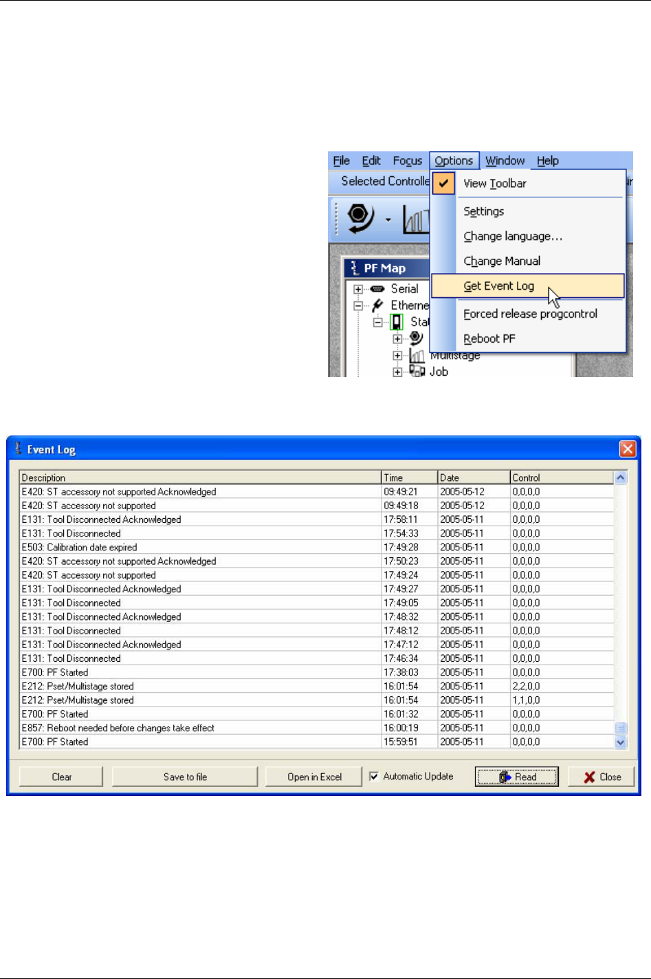
Event codes
25 Event codes
Event codes are displayed as pop up windows to inform users the status of the Power Focus. All events
are stored in the
Statistics event log or the General event log, depending on the event code type. Number
of events that can be stored in the log depends on memory configuration (see chapter
Controller). Once
the log is full, the oldest events will be overwritten by the most recent ones.
To open the event log, click
Get Event Log in the
Options list.
The
Event Log window appears.
Click
Clear to delete all events in the log.
Click
Save to file to store the event log as a text
file.
Click
Open in Excel to export the log to the
Microsoft Excel software.
Click
Read to update status of the event code
window.
When option
Automatic update is checked, the
events in the log are showed in “realtime” (in the
same way as event pop up widows).
9836 3123 01 311 (330)
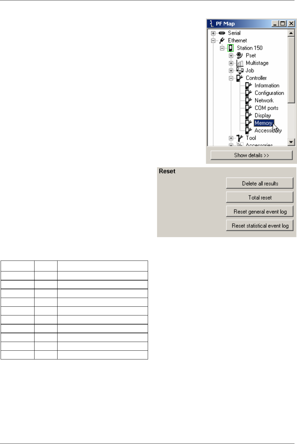
Event codes
The Statistic and General event log can also be cleared from the system
setup branch.
In PF Map, expand the
Controller branch and double-click Memory.
Click
Reset general event log and/or Reset statistical
event log
.
25.1 Event groups
Event code Group Description
E001-E099 0 Rundown failures
E100-E199 1 Event related errors
E200-E299 2 User input events
E300-E399 3 Statistical events
E400-E499 4 Communication events
E500-E599 5 Hardware events (tool)
E600-E699 6 Hardware events (DC3000/MC3000)
E700-E799 7 Hardware events
E800-E899 8 Software events
E900-E999 9 Events MMI3000
312 (330) 9836 3123 01

Event codes
25.2 Abbreviations
Abbreviation Description
ACK Acknowledgement
PFNR Power Focus not ready
TNR Tool not ready
TNR-marks on event codes do not affect status of “tool not ready”. However, since locking of
tool affects ”tool not ready”, the status will be true while an event code which requires
acknowledgement is displayed. Notice that this is due to tool lock and not the event code
itself.
LCK Tool locked
25.3 Event code list
25.3.1 Rundown failures
Event
code
Event name Information
E003 Torque measurement
possibly invalid
The programming is incorrect. Please check the programming and ensure there is some
movement on the socket in the second stage.
25.3.2 Event related errors
Event
code
Event name Information Note
E102 Rundown prohibited due to
Lock on Reject
This event code is displayed when an attempt to make a tightening is made and
tightenings are disabled by the parameter
Lock on reject [C210]. For more
information see section
Sub information for event codes.
TNR
LCK
E103 Tool locked by digital input The tool is locked by digital input. For more information see section Sub
information for event codes
.
TNR
LCK
E107 Rundown prohibited due to
Line control, batch not
enabled
A Job using line control is selected. The Job does not start until a line control
start signal is received. For more information see section
Sub information for
event codes
.
TNR
LCK
E112 Rehit An attempt to tighten an already tightened bolt was made.
E113 Current limit reached -
Rundown aborted
The current limit has been reached, the drive is disabled. ACK
PFNR
TNR
E117 Tool locked – cannot access
RBU
Power Focus cannot communicate with RBU and must be restarted to protect
data. For more information see section
Sub information for event codes.
PFNR
TNR
E120 Motor tuning failure Motor tuning failed. The trigger could have been released before the end of the
motor tuning or the tool has a defect.
ACK
PFNR
TNR
E121 Open end tuning failure This event indicates that the Open end tuning command has not been
successfully performed.
ACK
PFNR
TNR
E122 Open end positioning failure Open end positioning failed due to too much torque during positioning phase.
E125 Alarm on timeout / Alarm
on torque lost
When the function alarm on timeout is activated in the Pset, this event code
indicates that a timeout caused the tightening to be aborted. The timeout must
be the primary cause for the abort for this alarm to be activated.
E126 Multistage aborted This event indicates that the current running Multistage has not been performed
entirely (the drive has been shut off or the tool trigger was released before the
end). For more information see section
Sub information for event codes.
9836 3123 01 313 (330)

Event codes
Event Event name Information Note
code
E127 PVT shut off This event indicates that the drive was shut off in the selftap or prevail phase of
the rundown.
E128 Trigger lost When the function trigger lost is activated in the Pset, this event indicates that
the trigger of the tool was released before final target.
E129 Torque lower than target When the function torque lower than target is activated in the Pset, this event
indicates that the torque result is below final target. The torque status is NOK
even if the torque result was larger than final torque min.
E130 Post view torque shut off Post view torque conditions were not fulfilled. PFN
E131 Tool Disconnected This event code will be generated when the tool is disconnected (logically or
physically) from the PF. The event code is also generated when an attempt to
start a disconnected (logically or physically) tool is done. For more information
see section
Sub information for event codes.
A damaged cable can result in a disconnected tool.
ACK
PFNR
TNR
E132 Wrong tool start input
setting
Tool start select source [T200] is not corresponding to the remote start jumper
position. For remote start information see chapter
Connecting devices.
PFNR
TNR
E133 Tool locked by Tools Talk The tool is prohibited via ToolsTalk PF. For more information see section Sub
information for event codes
.
TNR
LCK
E134 MC Target input active at
start attempt
The target signal is active in the drive, although the tightening has been
acknowledged by the CC-card.
E136 Tool locked by batch OK This event code is displayed if the tool is locked by the function Lock at batch
OK [P152]
. For more information see section Sub information for event codes.
TNR
LCK
E137 Tool locked by Field bus The tool is locked by Field bus. For more information see section Sub
information for event codes
.
TNR
LCK
E138 Wrong tool start input
source
It is only possible to start the tool from selected tool start select source. Please
check the setting for
Tool start select source [T200].
E139 Tool locked by Open
protocol
The tool is locked by open protocol. For more information see section Sub
information for event codes
.
TNR
LCK
E140 Insert user ID card to release
tool
The tool is locked; the user must insert his ID card in the card reader to release
the tool. For more information see section
Sub information for event codes.
TNR
LCK
E141 Tool locked during work
order
Multiple identifiers; tool is locked during work order. Tool will be unlocked
when all expected identifiers have been received in correct order.
TNR
LCK
E145 Tool locked by Timer enable
tool
The tool is locked by digital input “timer enable tool”. TNR
LCK
E147 Tool locked by click wrench
Pset
A click wrench Pset is in use. For more information see section Sub information
for event codes
.
TNR
LCK
E149 Tool locked disable
loosening at OK
The function Disable loosening at OK [C220] has locked the tool. For more
information see section
Sub information for event codes.
TNR
LCK
E150 Job client does not respond When running a Cell Job, this event is displayed by the Job reference when one
of the Job members does not respond. For more information see section
Sub
information for event codes
.
E151 Job in OFF mode It is not possible to select a new Job. The Power Focus is in Job off mode.
E152 PF locked in Job mode This event appears when in a forced Cell Job an attempt is made to tighten with
a controller which is not currently active or when a controller has performed all
tightenings in the Job. For more information see section
Sub information for
event codes
.
TNR
LCK
E153 Not ok to select new Job A Job is currently running, it is not possible to select a new Job until the first is
finished in some way (completed or aborted). This message is also displayed if
a Job is selected on a Job member.
314 (330) 9836 3123 01

Event codes
9836 3123 01 315 (330)
Event
code
Event name Information Note
E154 Remote Job running When running a Cell Job, this is displayed by the Job members when a Cell Job
is selected on the Job reference.
E155 Remote Job aborted When running a Cell Job, this is displayed by the Job members when a Cell Job
is aborted.
E156 Job members lost When running a Cell Job, this is displayed by the Job reference when it has lost
contact with one of the Job members. For more information see section
Sub
information for event codes
.
E157 Job reference lost When running a Cell Job, this is displayed by the Job clients when they have
lost contact with their Job reference.
E158 Invalid Job ID When the selected Job does not exist.
E159 No Pset in selected Job When the selected Job does not contain any Pset.
E160 Job select source not valid Attempt to select a Job with the wrong input source.
E161 Line control alert 1 The line control has been activated, and the first control alert limit has been
reached.
E162 Line control alert 2 The line control has been activated, and the second control alert limit has been
reached.
E166 Job aborted This event will be displayed when a running Job is aborted. For more
information see section
Sub information for event codes.
E167 Max coherent Not OK
tightenings reached
When the number of NOT OK tightenings in a row is reached, then the tool
will be locked and can be unlocked only via a digital input (reset NOK
counter).
TNR
LCK
E175 Configuration will be erased
at next reboot
The Power Focus will erase the configuration in the Power Focus memory and
the RBU since the memory setup has been changed.
ACK
E176 IPM memory needed Not possible to configure this functionality without ”IPM memory”.
E177 Functionality not in RBU The user is trying to use functionality that is not enabled in the RBU.
E178 Memory allocation error The user is trying to allocate more memory than exists in the Power Focus.
E179 Totally configurable
memory needed
Not possible to configure this functionality without function “totally
configurable memory”. See section
Sub information for event codes.
E180 Euchner Ident System only
supports Siemens 3964R
protocol
The protocol setting for the serial COM port 1, parameter Protocol [C401], is
not set to “3964R”. It is not possible to use the Euchner Ident system with this
configuration.
E181 Not possible to read ID card It was not possible to read the ID card inserted in the Euchner system.
E190 Wrong ST scan source Attempt to scan from wrong source.
E191 ST scanner overheated The ST scanner temperature has exceeded max temperature.

Event codes
316 (330) 9836 3123 01
25.3.3 User input events
Event
code
Event name Information Note
E206 Pset number invalid An attempt was made to do a tightening with the wrong Pset within a Job.
For more information see section Sub information for event codes.
TNR
E207 Wrong Pset Select Source Attempt to select Pset from a source not specified for parameter Pset select
source [C200]
.
E208 Not ok to select new Pset It is not allowed to select new Pset when the already selected Pset is auto
selected by Job.
E211 Wrong identifier input source Wrong input source for an identifier string.
E212 Pset/Multistage stored Event displayed every time a Pset or Multistage is stored or restored.
For more information see section Sub information for event codes.
E220 Fastener broken Displayed if fastener (screw or nut) break during yield control
E221 Too few samples for yield
control
Too few samples for mean tq calculation in yield algorithm. Parameter "No
degrees" too small or speed too high during yield control.
E233 Final Target range error This event code is displayed when an attempt is made to tighten with a final
target out of range (larger than tool max torque or 9999).
For more information see section
Sub information for event codes.
TNR
E234 Start final angle range error This event code is displayed when an attempt is made to tighten with a Start
final angle [P120]
out of range.
For more information see section
Sub information for event codes.
TNR
E236 Configuration set inconsistent This event code is displayed if one device on the I/O bus has the correct ID
but incorrect type specified (for example a Selector is connected and a RE-
Alarm is configured).
For more information see section
Sub information for event codes.
PFNR
TNR
E237 Strategy configuration error No valid control strategy was chosen for the stored Pset.
For more information see section
Sub information for event codes.
TNR
E238 Not possible to run a
Multistage with a Click
Wrench Pset
An attempt was made to perform a Multistage tightening containing at least
one Pset with a click wrench strategy.
TNR
E240 Password Incorrect Input
Source
The password is entered from an invalid source according to the
configuration.
E250 Max time for first tightening
run out (Job)
This message is displayed and the Job is terminated if the first tightening is
not performed within the specified time.
E251 Max time to complete Job run
out
This message is displayed and the Job is terminated if the Job is not completed
within the specified time.

Event codes
9836 3123 01 317 (330)
25.3.4 Statistical events
Event
code
Event name Information
E333 Not allowed subscription The requested statistic subscription is not allowed. For example it is not allowed to set an
angle statistic subscription for a Pset using only the torque control strategy.
E334 No statistic available for
this Pset
The Pset strategy is not suitable to calculate statistics (no strategy is chosen).
E335 Not enough data Not enough data is available to calculate the statistic control limits.
E336 Mem alloc fail It is not possible to allocate enough memory for the statistic subscription.
E340 Xucl tq The last subgroup mean torque value is larger than the upper control limit.
E341 Xlcl tq The last subgroup mean torque value is lower than the lower control limit.
E342 Rucl tq The last subgroup range torque value is larger than the upper control limit.
E343 Rlcl tq The last subgroup range torque value is lower than the lower control limit.
E344 Cp tq The torque Cp is lower than 2.
E345 Cpk tq The torque Cpk is lower than 1,33.
E346 7inc x tq Trend deviation alarm, the subgroup torque mean value has increased 7 times
consecutively.
E347 7dec x tq Trend deviation alarm, the subgroup torque mean value has decreased 7 times
consecutively.
E348 7inc r tq Trend deviation alarm, the subgroup torque range value has increased 7 times
consecutively.
E349 7dec r tq Trend deviation alarm, the subgroup torque range value has decreased 7 times
consecutively.
E350 7above x tq Trend deviation alarm, the subgroup torque mean value has been above the average mean
value of the average of the latest ten subgroups 7 times consecutively.
E351 7below x tq Trend deviation alarm, the subgroup torque mean value has been below the average mean
value of the average of the latest ten subgroups 7 times consecutively.
E352 7above r tq Trend deviation alarm, the subgroup torque range value has been above the average range
value of the average of the latest ten subgroups 7 times consecutively.
E353 7below r tq Trend deviation alarm, the subgroup torque range value has been below the average range
value of the average of the latest ten subgroups 7 times consecutively.
E354 2sigma x tq Trend deviation alarm, the last subgroup torque average is outside Xtq-bar-bar - 2 sigma.
E355 2sigma r tq Trend deviation alarm, the last subgroup torque range average is outside Rtq-bar-bar - 2
sigma.
E360 Xucl ang The last subgroup mean angle value is larger than the upper control limit.
E361 Xlcl ang The last subgroup mean angle value is lower than the lower control limit.
E362 Rucl ang The last subgroup range angle value is larger than the upper control limit.
E363 Rlcl ang The last subgroup range angle value is lower than the lower control limit.
E364 Cp ang The angle Cp is lower than 2.
E365 Cpk ang The angle Cpk is lower than 1.33.
E366 7inc x ang Trend deviation alarm, the subgroup angle mean value has increased 7 times
consecutively.
E367 7dec x ang Trend deviation alarm, the subgroup angle mean value has decreased 7 times
consecutively.
E368 7inc r ang Trend deviation alarm, the subgroup angle range value has increased 7 times
consecutively.
E369 7dec r ang Trend deviation alarm, the subgroup angle range value has decreased 7 times
consecutively.

Event codes
318 (330) 9836 3123 01
Event
code
Event name Information
E370 7above x ang Trend deviation alarm, the subgroup angle mean value has been above the average mean
value of the average of the latest ten subgroups 7 times consecutively.
E371 7below x ang Trend deviation alarm, the subgroup angle mean value has been below the average mean
value of the average of the latest ten subgroups 7 times consecutively.
E372 7above r ang Trend deviation alarm, the subgroup angle range value has been above the average range
value of the average of the latest ten subgroups 7 times consecutively.
E373 7below r ang Trend deviation alarm, the subgroup angle range value has been below the average range
value of the average of the latest ten subgroups 7 times consecutively.
E374 2sigma x ang Trend deviation alarm, the last subgroup angle average is outside Xang-bar-bar-2 sigma.
E375 2sigma r ang Trend deviation alarm, the last subgroup angle range average is outside Rang-bar-bar-2
sigma.
E380 Xucl cm The last subgroup mean CM value is larger than the upper control limit.
E381 Xlcl cm The last subgroup mean CM value is lower than the lower control limit.
E382 Rucl cm The last subgroup range CM value is larger than the upper control limit.
E383 Rlcl cm The last subgroup range CM value is lower than the lower control limit.
E384 Cp cm The CM Cp is lower than 2.
E385 Cpk cm The CM Cpk is lower than 1.33.
E386 7inc x cm Trend deviation alarm, the subgroup CM mean value has increased 7 times consecutively.
E387 7dec x cm Trend deviation alarm, the subgroup CM mean value has decreased 7 times consecutively.
E388 7inc r cm Trend deviation alarm, the subgroup CM range value has increased 7 times consecutively.
E389 7dec r cm Trend deviation alarm, the subgroup torque range value has decreased 7 times
consecutively.
E390 7above x cm Trend deviation alarm, the subgroup CM mean value has been above the average mean
value of the average of the latest ten subgroups 7 times consecutively.
E391 7below x cm Trend deviation alarm, the subgroup torque mean value has been below the average mean
value of the average of the latest ten subgroups 7 times consecutively.
E392 7above r cm Trend deviation alarm, the subgroup CM range value has been above the average range
value of the average of the latest ten subgroups 7 times consecutively.
E393 7below r cm Trend deviation alarm, the subgroup CM range value has been below the average range
value of the average of the latest ten subgroups 7 times consecutively.
E394 2sigma x cm Trend deviation alarm, the last subgroup CM average is outside XCM-bar-bar-2 sigma.
E395 2sigma r cm Trend deviation alarm, the last subgroup CM range average is outside RCM-bar-bar-2
sigma.

Event codes
9836 3123 01 319 (330)
25.3.5 Communication events
Event
code
Event name Information Note
E401 Duplicate device IDs on
I/O bus
Two I/O-devices with the same ID are present on the I/O bus. PFNR
TNR
ACK
E403 I/O-device not
responding
I/O-device is not properly connected or the ID of the device is not the same as the
one configured. For more information see section
Sub information for event codes.
PFNR
TNR
E404 Selector is not connected
or not responding
The Selector is not properly connected or the ID of the Selector is not the same as
the one configured. For more information see section
Sub information for event
codes
.
PFNR
TNR
E405 I/O Expander is not
connected or not
responding
The I/O Expander is not properly connected or the ID of the I/O Expander is not
the same as the one configured. For more information see section
Sub information
for event codes
.
PFNR
TNR
E406 RE-Alarm is not
connected or not
responding
The remote alarm is not properly connected or the ID of the remote alarm is not the
same as the one configured. For more information see section
Sub information for
event codes
.
PFNR
TNR
E417 Too many
communication sessions
at one time
There are too many connections at the same time (ToolsTalk PF, Tools Net,
Operator Panel etc.)
E420 ST Accessory not
supported.
Unknown device, not supported in this release connected to the ST bus. PFNR
TNR
ACK
E421 Safety trigger not
supported by tool
software
The tool software version does not support safety trigger function. PFNR
TNR
E433 No RBU present No RBU detected at start-up or RBU found missing at runtime. PFNR
TNR
E434 RBU Timeout RBU did not respond to command from Power Focus. PFNR
TNR
E436 RBU file system
warning
There has been a repairable fault in the RBU file system, e.g. power-off or other
interruption during download.
E437 RBU file system corrupt The RBU file system has too many faults. An attempt will be made to repair it by
means of erasing the RBU.
PFNR
TNR
E438 RBU file mismatch A file with incorrect name or size was returned to a read request. PFNR
TNR
E440 RBU no files A file type is not present in the RBU at start-up. PFNR
TNR
E441 RBU access too busy RBU has answered to the poll but Power Focus is too busy to receive the reply. ACK
PFNR
E442 RBU no such file A file has not been localised in the RBU. The RBU is corrupt or not present. PFNR
TNR
E444 RBU packet rejected RBU responds with an answer not matching the last request. This is probably due
to duplicates sent when the Power Focus does not acknowledge packages.
PFNR
TNR
E445 RBU corrupt The RBU is corrupt. PFNR
TNR
E446 RBU read error Read operation failed. PFNR
TNR
E447 RBU write error Write operation failed. PFNR
TNR

Event codes
320 (330) 9836 3123 01
Event
code
Event name Information Note
E448 RBU delete error Delete operation failed. PFNR
TNR
E449 RBU flush error RBU erase failed. PFNR
TNR
E450 RBU list error Update operation failed. PFNR
TNR
E451 RBU update failed Database synchronisation between Power Focus and RBU failed. PFNR
TNR
E460 Field bus type mailbox
message fault
Error detected in initialisation of Field bus.
E461 Field bus type gen com
fault
Error detected in initialisation of Field bus.
E462 Field bus mailbox
message fault
Error detected in initialisation of Field bus.
E463 Field bus gen com fault Error detected in initialisation of Field bus.
E464 Field bus hardware fault The Field bus module is broken and has to be replaced. PFNR
TNR
E465 Field bus dip switch
error
The software tries to configure the value of node address or baud rate, but the
address switch on the Field bus module is not in the right position to enable
software setting. Set switches in the right position and then turn on the power.
E466 Field bus offline The Field bus went from online to offline. This is just a warning.
E467 Field bus configuration
fault
Error detected in initialisation of Field bus.
E468 Field bus hardware
mismatch
The Field bus module installed in Power Focus is not the same Field bus type as
configured with ToolsTalk PF. Change Field bus module or configuration to get a
match.
E469 Field bus init error Error detected in initialisation of Field bus.
E470 Field bus PCP error InterBus PCP length error.
E471 Field bus claim area
failed, lost one message
One packet lost.
E472 Field bus release area
timeout
Release area command timed out.
E473 Field bus
communication buffer
alarm
Communication buffer full. Decrease Field bus update timer.
E474 Field bus monitor buffer
alarm
Field bus monitor buffer full. Turn off Field bus monitor mode.
E475 Field bus PsetID
mismatch Selector lifted
socket
Field bus selected Pset does not file the lifted socket.
E480 Channel ID not valid The channel ID configured is not within the limits permitted. The channel ID must
be configured between 1 and 20.
PFNR
TNR
E481 Cell member registration
failed
The Cell member registration failed because one Cell member is already registered
with the same channel ID.
PFNR
TNR
E490 Cell ID not valid The Cell ID configured is not within the limits permitted. The Cell ID must be
configured between 1 and 999.
PFNR
TNR
E491 Net member registration
failed
The Net member registration failed because one Net member is already registered
with the same Cell ID.
PFNR
TNR

Event codes
25.3.6 Hardware events (tools)
Event
code
Event name Information Note
E501 Tool overheated The tool is to hot and the drive is disabled. For more information see
section
Sub information for event codes.
PFNR
TNR
E502 Tool service interval expired Service the tool. See parameter Service interval [T413]. ACK
E503 Calibration date expired The calibration date has expired.
E504 Tool wear indicator alarm Tool wear indicator alarm indicates that the tool should be serviced. PFNR
E505 Tool rebuilt to/from OE-type Tool redesigned. E.g. angled tool type redesigned to an OE-tool type. PFNR
TNR
ACK
E510 Tool type not supported by RBU The tool type is not supported by RBU. PFNR
TNR
ACK
E511 Tool-Power Focus 3000 size
mismatch
Mismatch between the tool and the controller (for example S4/S7 tool
connected to a S9 controller).
For more information see section
Sub information for event codes.
PFNR
TNR
ACK
E513 Tool EEPROM corrupt - service
tool
Checksum indicates that tool memory is corrupt. Tool must be serviced. PFNR
TNR
ACK
E514 Tool EEPROM corrupt -Motor
tune
Checksum indicates that motor tuning or Open end tuning table is corrupt.
Do a motor tuning or Open end tuning.
For more information see section
Sub information for event codes.
PFNR
TNR
ACK
E517 Tool max torque invalid Tool max torque invalid, service tool. PFNR
TNR
ACK
E518 Tool normalisation out of range Tool normalisation value out of range, service tool. PFNR
TNR
ACK
E519 Tool calibration value out of
range
Tool calibration value out of range, service tool. PFNR
TNR
ACK
E520 Wear indicator data in tool
invalid
Data in tool memory used for wear indicator is invalid. Service tool.
E531 Communication error Communication error. Restart the controller.
Only available for Tensor DS/DL.
ACK
E535 Torque transducer error Cables to transducer cut off or shorted. PFNR
TNR
ACK
E536 No transducer (sensor) Cables to transducer cut off or shorted. PFNR
TNR
E537 Calibration not OK, offset
outside limits
Calibration offset outside limits. PFNR
TNR
E538 Calibration not OK, CalVal
outside limits
Calibration value outside limits. PFNR
TNR
9836 3123 01 321 (330)

Event codes
322 (330) 9836 3123 01
Event
code
Event name Information Note
E539 Calibration not OK, Offset
changed > 5% of max value
since last calibration
Calibration not OK, offset changed > 5% of max value since last
calibration.
E540 Calibration not OK, CalVal
changed > 5% of max value
since last calibration
Calibration not OK, calibration value changed > 5% of max value since
last calibration.
ACK
E541 Transducer (sensor) lost during
tightening
Cables to transducer cut off or shorted. PFNR
TNR
E550 Radio contact with tool
established, tool accessible
Radio contact with tool established, tool accessible.
E551 Radio contact with tool lost, tool
inaccessible
Radio contact with tool lost, tool inaccessible.
E552 DASP Communication error
with tool
Communication error between tool and controller on DASP level. Not to
possible to read or write from/to an ALP reference.
E553 Pairing attempt with wireless
tool failed
An attempt to pair the Power Focus with a wireless tool failed.
E554 Command not performed,
wireless tool inaccessible
A command (batch increment, reset batch etc.) could not be performed and
was discarded because the tool was currently inaccessible.
E555 Condition change not reflected
in tool, wireless tool
inaccessible
A condition change in the controller (Pset selection, Job selection, Job
aborted etc.) could not be reflected in the tool. The tool was currently
inaccessible.
E556 Tool battery low Tool battery low.
25.3.7 Hardware events (DC3000/MC3000)
Event
code
Event name Information Note
E601 System voltage low DC voltage too low PFNR
TNR
ACK
E603 Drive overheated The DC drive is too hot, drive deactivated. TNR
E618 Drive HW/SW mismatch Drive hardware and software mismatch.
Check motor type in ToolsTalk DS/DL.
ACK
E619 Drive deactivated DC drive deactivated during operation.
E620 Tool stall Tool motor stall.
E621 High current offset High current offset at tightening start

Event codes
9836 3123 01 323 (330)
25.3.8 Hardware events
Event
code
Event name Information Note
E700 PF started This event code is only visible in the event log and used when the PF is started.
E701 Backup battery low level The backup battery level is low. The battery should be changed soon.
Contact the local Atlas Copco service representative.
E702 Backup battery empty or
missing
The backup battery level is very low or the battery is missing. A new battery
should be inserted as soon as possible.
Contact the local Atlas Copco service representative.
PFNR
TNR
ACK
E710 ACTA/QRTT calibration An ACTA/QRTT calibration has been performed.
E720 Earth failure in ST tool An earth (ground) fail detected, probably a cable failure. PFNR
TNR
E721 Internal ST tool failure Diode (LED) board in ST tool disconnected. Tool service needed. PFNR
TNR
E722 Illegal ring position The reverse ring is not in a defined position. PFNR
25.3.9 Software events
Event
code
Event name Information Note
E805 PF Model unknown This event is displayed after start-up when the RBU is missing, or when the RBU
revision cannot be supported by the controller (e.g. RBU bronze on a PF Graph
controller), or when the RBU license file is missing or cannot be read by the boot
code.
PFNR
TNR
E808 Error condition detected
by software
An error condition was detected by software.
E810 Database is corrupt Database must be cleared, the database version is not correct.
E822 No Job ACK from
control
Tightening initialisation phase failed. Hardware failure. PFNR
TNR
ACK
E823 No calibration result No calibration was received from the drive during the tightening initialisation
phase (timeout 100 ms).
PFNR
TNR
ACK
E824 Cycle abort timeout No tightening result was received from the drive before the cycle abort timeout.
The cycle abort timer is configurable in the Pset.
E831 Autoset wrong angle Autoset could not be executed, the angle results of the tightening performed were
null.
E833 Autoset tight NOK result The Autoset could not be executed, four NOK tightenings were performed.
E834 Autoset rejected Pset in
CCW direction
The Autoset was not allowed by the Power Focus for this Pset because the Pset
was configured in the CCW direction. Autoset is only permitted on a CW Pset.
E840 Feature Not Available In
Software Revision
This event is displayed when an attempt is made to run Multistage with a RBU
bronze, or handle a Pset with a PsetID larger than the max number of Psets (larger
than 64 for RBU bronze or larger than the configured value for RBU gold and
silver.
E841 SW function Not
Available for this tool
type
The software function is not available for this tool type.
E851 Connection with Tools
Net server lost
The connection with the Tools Net server was lost; the Power Focus is trying to
reconnect. The Tools Net server might be down or it might be an Ethernet cable
problem.
E856 Router unreachable The router in the configuration setting could not be reached. Check the network
configuration and in particularly the subnet mask and the default router.

Event codes
324 (330) 9836 3123 01
Event
code
Event name Information Note
E857 Reboot needed before
changes take effect
The configuration changes will not take effect until a system reboot. ACK
E858 IP address already in use The IP address of this PF is already in use by another system. ACK
E859 IP address collision Another system attempts to use the same IP address as this PF.
E862 Ethernet overload Error The Ethernet driver of the PF is temporarily switched off due to an overloaded
network.
E863 IP Port already in use An attempt was made to bind a TCP or UDP socket to a port already in use. For
instance, a user protocol might be using the same port as ToolsTalk PF.
E864 Ethernet echo detected An Ethernet packet was discarded, since its source MAC address was equal to the
Power Focus’ own MAC address. Notice that this message only occurs once
during runtime, even if several such packets are detected. There is most likely a
problem in the network.
E870 Sync member
registration failure
The Sync member registration failed. Two Sync members can have the same
channel ID or one Power Focus with a Sync reference IP address is missing in the
Sync list.
TNR
E871 Sync reference
configuration failure
The channel ID of the Sync reference is not first in the Sync list as required. PFNR
TNR
E872 Sync initialisation failure Tightening synchronisation initialisation failed. Check the I/O bus cable, check
that all the Sync members have the same active Pset and check the external start
bridge.
TNR
E873 SynchroTork not yet
implemented
SynchroTork not yet implemented, check the Sync configuration. TNR
E874 Sync members missing Only Sync reference is defined in the Sync list.
25.3.10 Events MMI3000
Event code Event name Information Note
E901 MMI Start-up Error Error in MMI detected. PFNR
TNR
ACK
25.4 Sub information for event codes
Each event code is logged together with four integer parameters. For some event codes these parameters
are used to store extra information about the event.
The follow sections contain event codes and explanations of the related integer parameters.

Event codes
9836 3123 01 325 (330)
25.4.1 E102, E103, E107, E117, E131, E133, E137, E139, E140, E146,
E147, E149, E152, E206, E501, E511 and E514
In case the tool is locked while a user attempts to start a service (normally tightening or loosening), the
Power Focus will show an event code to explain why or by which functionality the tool is locked. In case
the tool becomes locked while a service is performed, the service will be aborted and an event code
explaining why or by which functionality the tool was locked will be displayed.
The event codes messages generated because the tool is locked do contain two integer parameters that can
be viewed from the event log.
The first parameter explains which service that was denied or aborted (see table below).
Parameter Definition
0 Tightening
1 Loosening
2 Positioning (Open end tool only)
3 Motor tuning
4 Open end tuning (Open end tool only)
5 Tracking
The second parameter explains if the service was denied during start attempt or aborted while performed
(0 = Service denied, 1 = Service aborted).
The third and fourth parameters are not in use.
For more information see chapter Tool.
25.4.2 E112
The first parameter contains the Pset/Multistage ID number.
The second parameter states whether it is a Pset (1) or a Multistage (2).
Third and fourth parameters are not in use.

Event codes
326 (330) 9836 3123 01
25.4.3 E126
When running Multistage and Multistage abort [E126] with parameters (table 21-14) is displayed.
Parameter Definition
1 The stage when the Multistage aborted.
2 The possible event code for that stage.
3 Possible tightening error bits part I (bit 0-6; dec. 1-127) (more information below).
4 Possible tightening error bits part II (bit 0-15; dec. 1-65535) (more information below).
Possible tightening error bits part I (bit 0-6; dec. 1-127)
Tightening error bits show what went wrong with the tightening (only a few correspond to event codes).
All bits are sent as an unsigned 16 bit integer.
Bit Decimal value Event
0 1 Multistage aborted
1 2 Rehit
2 4 Torque measurement possibly invalid (for DS Tool only)
3 8 Current limit reached
4 16 Timeout on end time shutoff
5 32 Not used
6 64 Other
Possible tightening error bits part II (bit 0-15; dec.1-65535)
Tightening error bits show what went wrong with the tightening (only a few correspond to event codes).
All bits are sent as an unsigned 16 bit integer.
Bit Decimal value Event
0 1 Rundown angle max exceeded
1 2 Rundown angle min not reached
2 4 Final torque max exceeded
3 8 Final angle max exceeded
4 16 Self tap max exceeded
5 32 Self tap min not reached
6 64 PVT monitoring max exceeded
7 128 PVT monitoring min not reached
8 256 PVT Compensate overflow
9 512 Current monitoring max exceeded
10 1024 Post view torque min not reached
11 2048 Post view torque max exceeded
12 4096 Post view torque angle too small
13 8192 Trigger lost
14 16384 Torque less than target
15 32768 Tool hot

Event codes
Example: E126 (3, 129, 1, 16896)
The event code E126 means Multistage aborted.
The first parameter string number means that the Multistage was aborted in stage number three.
The second parameter string number means that event code E129, torque lower than target, occurred (in
stage number three).
The third parameter string number means: 1
10
= 0001
2
. Bit 0 means “Multistage aborted”.
The fourth parameter string number means: 16896
10
= 0100 0010 0000 0000
2
. Bit 9 means “current
monitoring max exceeded” and bit 14 means “torque less than target”.
Current limit reached is one of few event codes for which there is a corresponding
tightening result error bit.
25.4.4 E150
The first parameter contains the Channel ID number [C310] for the Job client not responding.
The second, third and fourth parameters are not in use.
25.4.5 E156
The first parameter contains the Channel ID number [C310] for the lost Job client.
The second, third and fourth parameters are not in use.
25.4.6 E166
The first parameter gives the ABORT source:
2: Digital input.
3: Ethernet/serial (PC).
5: Field bus.
6: Keyboard.
7 - 8: Reserved.
9: Manual mode (a Job is active and a new Job is selected from digital input. The current Job is aborted
and the new Job becomes active).
10: Timer 1 (max time to start Job).
11: Timer 2 (max time to complete Job).
12: Deleted (a pending Job is deleted from Power Focus database).
13: Job off mode.
14: Line control Alarm 2
15: Job override
The second, third and fourth parameters are not in use.
9836 3123 01 327 (330)

Event codes
328 (330) 9836 3123 01
25.4.7 E233, E234 and E237
Parameter Definition
1 Pset number.
2 Parameter number with an incorrect value.
3 Incorrect parameter (2) is dependent on this parameter.
4 Incorrect parameter (2) violates this limit.
Example: E233 (1, 113, 0, 9999)
1: Strategy configuration error in Pset number 1.
113: Pset parameter 113
Final target [P113] incorrect.
0: No valid information.
9999: Parameter 113 violates limit 9999.
Example: E237 (2, 110, 115, 0)
2: Strategy configuration error in Pset number 2.
110: Pset parameter
Cycle start [P110] incorrect.
115: Parameter 110,
Cycle start [P110], dependent of parameter 115, Cycle complete [P115].
0: No valid information.
25.4.8 E236
The first parameter contains the number of the I/O-device with problematic configuration.
The second parameter contains the type of I/O-device (3=RE-Alarm, 2=I/O Expander/Operator Panel, 5 =
four position socket selector, 6 = eight position socket selector).
The third and fourth parameters are not in use.
25.4.9 E403, E404, E405 and E406
The first parameter contains I/O-device ID of the not responding I/O-device.
The second, third and fourth parameters are not in use.

Event codes
9836 3123 01 329 (330)
25.4.10 E710
When an ACTA/QRTT calibration batch is completed, event code ACTA/QRTT calibration [E710] is
displayed.
Parameter Definition
1 Torque result bits (bit 0-10; dec. 1-2048) (more information below).
2 Angle result bits (bit 0-9; dec. 1-1024) (more information below).
3 Not used.
4 Channel number.
Torque result bits (bit 0-10; dec. 1-2048)
Torque result bits show the result of the torque calibration. All bits are sent as an unsigned 16 bit integer.
Bit Decimal value Event
0 1 Batch result torque OK.
1 2 Torque min failed.
2 4 Torque max failed.
3 8 Torque LCLx failed.
4 16 Torque UCLx failed.
5 32 Torque LCLr failed.
6 64 Torque UCLr failed.
7 128 Torque CP > failed.
8 512 Torque CPK > failed.
9 1024 Torque CAM > failed.
10 2048 T Diff < failed.
Angle result bits (bit 0-9; dec. 1-1024)
Angle result bits show the result of the angle calibration. All bits are sent as an unsigned 16 bit integer.
Bit Decimal value Event
0 1 Batch result angle OK.
1 2 Angle min failed.
2 4 Angle max failed.
3 8 Angle LCLx failed.
4 16 Angle UCLx failed.
5 32 Angle LCLr failed.
6 64 Angle UCLr failed.
7 128 Angle CP > failed.
8 256 Angle CPK > failed.
9 512 Angle CAM > failed.

9836 3123 01
Edition 1
Software Release W7.0
2007-04
www.atlascopco.com
