Torque Tool Ethernet Driver
© 2024 PTC Inc. All Rights Reserved.

Torque Tool Ethernet Driver
Table of Contents
Torque Tool Ethernet Driver
1
Table of Contents
2
Torque Tool Ethernet Driver
5
Overview
5
Setup
5
Channel Properties — General 6
Tag Counts 6
Channel Properties — Ethernet Communications 7
Channel Properties — Write Optimizations 7
Channel Properties — Advanced 8
Device Properties — General 9
Operating Mode 10
Tag Counts 10
Device Properties — Scan Mode 10
Device Properties — Timing 11
Device Properties — Communications Parameters 12
Device Properties — Settings 13
Device Properties — Redundancy 14
Optimizing Communications
15
Data Types Description
16
Address Descriptions
17
Message IDs
18
Command Set: Alarm
20
Command Set: Auto-Disable Settings
21
Command Set: Communication
22
Command Set: Dynamic Job Request
23
Command Set: Flash
23
Command Set: Identifiers
23
Command Set: IO Interface
24
Command Set: Job Info
26
Command Set: Job Data
27
Command Set: Job Number Data
29
Command Set: Last Tightening Results
29
Command Set: Multi-Spindle Results
34
Command Set: Old Tightening Results
36
www. ptc.com
2

Torque Tool Ethernet Driver
Command Set: Operation Result
40
Command Set: Parameter Set Data
40
Command Set: Parameter Set Numbers
41
Command Set: Parameter Set Selected
42
Command Set: Program Messages
43
Command Set: Selector Messages
43
Command Set: Time
44
Command Set: Tool Data
45
Command Set: Trace Curve Data Messages
47
Command Set: User Data Messages
49
Command Set: VIN
49
Event Log Messages
50
Error Descriptions
50
Address <address> is out of range for the specified device or register. 51
Array size is out of range for address <address>. 51
Array support is not available for the specified address: <address>. 51
Data type <type> is not valid for device address <address>. 51
Device address <address> contains a syntax error. 51
Device address <address> is read only. 52
Subscription failed for device <device>, <type> subscription. 52
Unable to bind to adapter: <adapter name>. Connect failed. 52
Winsock initialization failed (OS error = <error>). 52
Winsock shut down failed (OS error = <error>). 53
Winsock V1.1 or higher must be installed to use the driver. 53
Device <device name> failed to connect. 53
Device <device name> is not responding. 53
Unable to read tag <tag name>: Device <device name> encountered a parsing error. 54
Unable to read tag <tag name>: Device <device name> received an error response (Error <error
code>). 54
Unable to read unsolicited packed data group: Device <device name> received an error response
(Error <error code>). 55
Unable to write tag <tag name>: Device <device name> encountered a parsing error. 55
Unable to write tag <tag name>: Device <device name> received an error response (Error <error
code>). 55
Unable to write tag <tag name>: Device <device name> received invalid data for write. 56
Unable to write to <address> on device <device name>. 56
Error Codes 56
Appendix — Dynamic Job Request
60
www. ptc.com
3


Torque Tool Ethernet Driver
Torque Tool Ethernet Driver
Help version 1.087
CONTENTS
Overview
What is the Torque Tool Ethernet Driver?
Setup
How do I configure a device for use with this driver?
Optimizing Communications
How do I get the best performance from the driver?
Data Types Description
What data types does the Torque Tool Ethernet Driver support?
Address Descriptions
How do I reference a data location in a Torque Tool Ethernet device?
Error Descriptions
What error messages does the Torque Tool Ethernet Driver produce?
Overview
The Torque Tool Ethernet Driver provides a reliable way to connect Torque Tool Ethernet devices to OPC Cli-
ent applications; including HMI, SCADA, Historian, MES, ERP, and countless custom applications. It is inten-
ded to work with all devices supporting the Torque Tool Open Protocol.
Setup
Supported Devices
The Torque Tool Ethernet Driver is designed to work with any device that supports the Torque Tool Open
Protocol. The driver has been tested with the Stanley QA Alpha Controller and the Atlas Copco Power Focus.
Channel and Device Limits
The maximum number of channels supported by this driver is 1024. The maximum number of devices sup-
ported by this driver is 1024 per channel.
www. ptc.com
5
Torque Tool Ethernet Driver
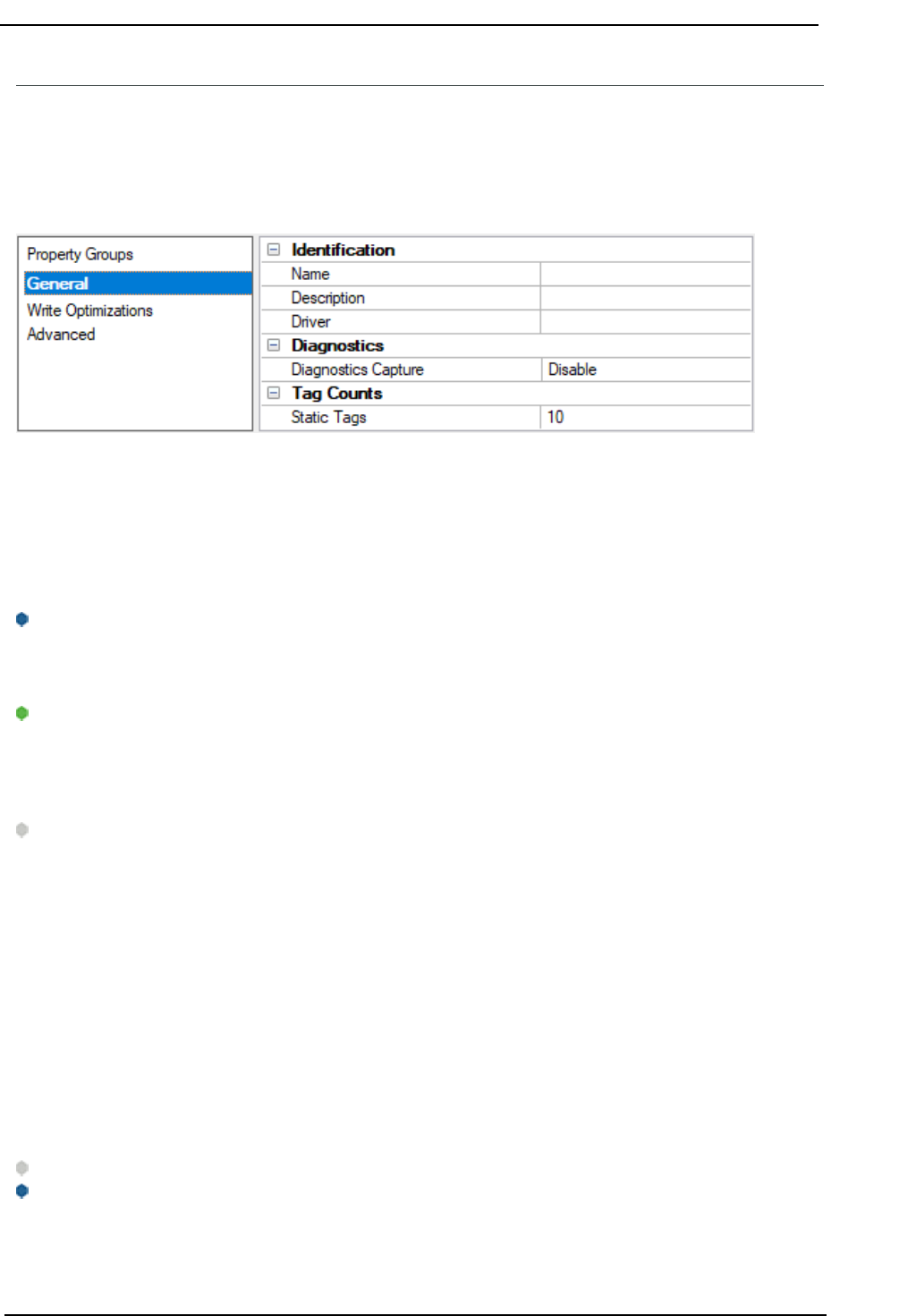
Channel Properties — General
This server supports the use of multiple simultaneous communications drivers. Each protocol or driver used
in a server project is called a channel. A server project may consist of many channels with the same com-
munications driver or with unique communications drivers. A channel acts as the basic building block of an
OPC link. This group is used to specify general channel properties, such as the identification attributes and
operating mode.
Identification
Name:Specify the user-defined identity of this channel. In each server project, each channel name must be
unique. Although names can be up to 256 characters, some client applications have a limited display win-
dow when browsing the OPCserver's tag space. The channel name is part of the OPC browser information.
The property is required for creating a channel.
For information on reserved characters, refer to "How To... Properly Name a Channel, Device, Tag, and Tag
Group" in the server help.
Description: Specify user-defined information about this channel.
Many of these properties, including Description, have an associated system tag.
Driver:Specify the protocol / driver for this channel. Specify the device driver that was selected during chan-
nel creation. It is a disabled setting in the channel properties. The property is required for creating a chan-
nel.
Note: With the server's online full-time operation, these properties can be changed at any time. This
includes changing the channel name to prevent clients from registering data with the server. If a client has
already acquired an item from the server before the channel name is changed, the items are unaffected. If,
after the channel name has been changed, the client application releases the item and attempts to re-
acquire using the old channel name, the item is not accepted. Changes to the properties should not be
made once a large client application has been developed. Utilize proper user role and privilege man-
agement to prevent operators from changing properties or accessing server features.
Diagnostics
Diagnostics Capture: When enabled, this option makes the channel's diagnostic information available to
OPC applications. Because the server's diagnostic features require a minimal amount of overhead pro-
cessing, it is recommended that they be utilized when needed and disabled when not. The default is dis-
abled.
Note:This property is not available if the driver does not support diagnostics.
For more information, refer to "Communication Diagnostics" and "Statistics Tags"in the server help.
Tag Counts
www. ptc.com
6
Torque Tool Ethernet Driver
Static Tags:Provides the total number of defined static tags at this level (device or channel). This inform-
ation can be helpful in troubleshooting and load balancing.
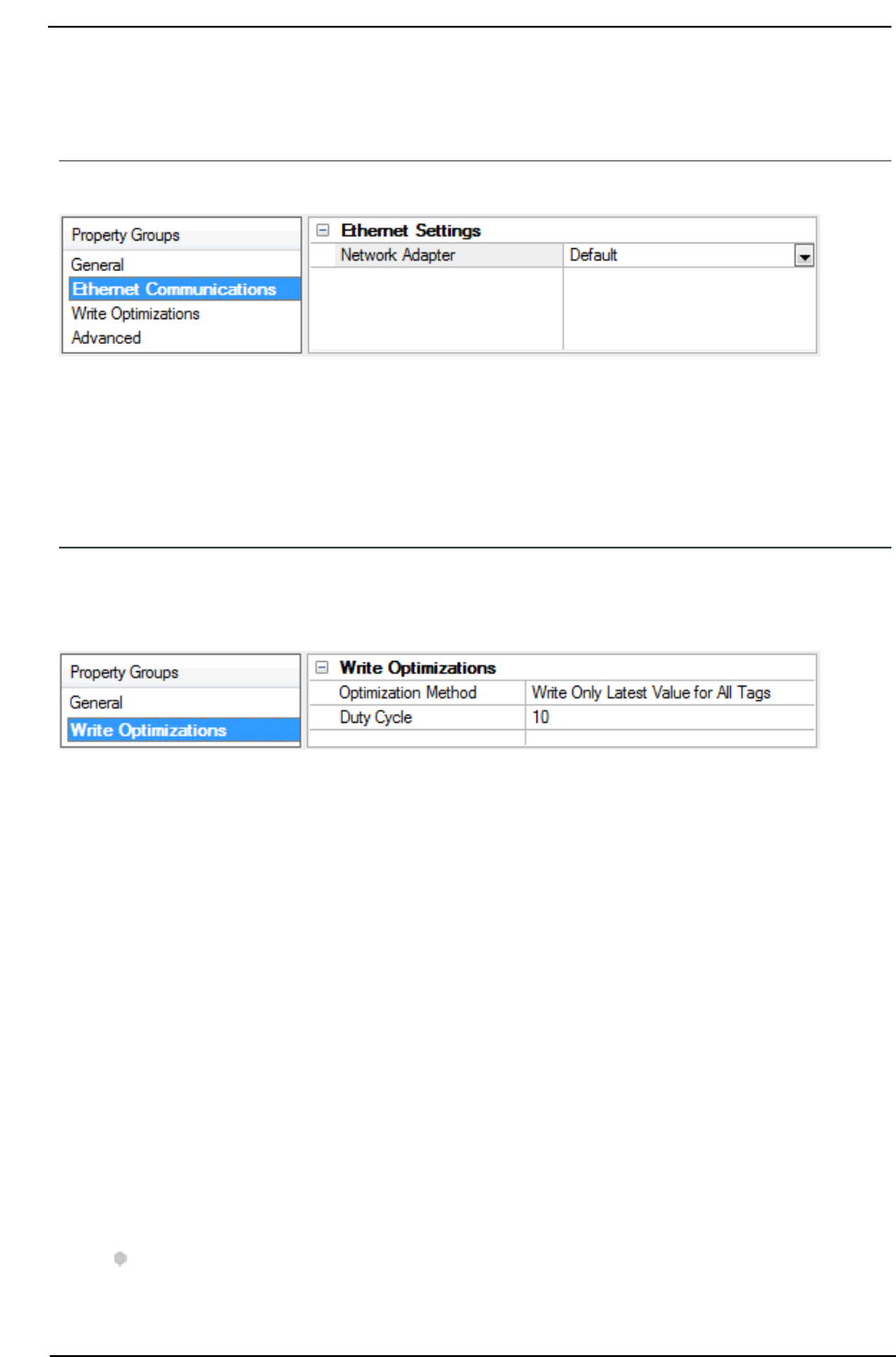
Channel Properties — Ethernet Communications
Ethernet Communication can be used to communicate with devices.
Ethernet Settings
Network Adapter:Specify the network adapter to bind. When left blank or Default is selected, the oper-
ating system selects the default adapter.
Channel Properties — Write Optimizations
The server must ensure that the data written from the client application gets to the device on time. Given
this goal, the server provides optimization properties to meet specific needs or improve application respons-
iveness.
Write Optimizations
OptimizationMethod: Controls how write data is passed to the underlying communications driver. The
options are:
l
Write All Values for All Tags:This option forces the server to attempt to write every value to the
controller. In this mode, the server continues to gather write requests and add them to the server's
internal write queue. The server processes the write queue and attempts to empty it by writing data
to the device as quickly as possible. This mode ensures that everything written from the client applic-
ations is sent to the target device. This mode should be selected if the write operation order or the
write item's content must uniquely be seen at the target device.
l
WriteOnlyLatest Value forNon-BooleanTags: Many consecutive writes to the same value can
accumulate in the write queue due to the time required to actually send the data to the device. If the
server updates a write value that has already been placed in the write queue, far fewer writes are
needed to reach the same final output value. In this way, no extra writes accumulate in the server's
queue. When the user stops moving the slide switch, the value in the device is at the correct value at
virtually the same time. As the mode states, any value that is not a Boolean value is updated in the
server's internal write queue and sent to the device at the next possible opportunity. This can greatly
improve the application performance.
Note: This option does not attempt to optimize writes to Boolean values. It allows users to optim-
www. ptc.com
7
Torque Tool Ethernet Driver
ize the operation of HMI data without causing problems with Boolean operations, such as a moment-
ary push button.
l
WriteOnlyLatestValueforAllTags:This option takes the theory behind the second optimization
mode and applies it to all tags. It is especially useful if the application only needs to send the latest
value to the device. This mode optimizes all writes by updating the tags currently in the write queue
before they are sent. This is the default mode.
Duty Cycle: is used to control the ratio of write to read operations. The ratio is always based on one read
for every one to ten writes. The duty cycle is set to ten by default, meaning that ten writes occur for each
read operation. Although the application is performing a large number of continuous writes, it must be
ensured that read data is still given time to process. A setting of one results in one read operation for every
write operation. If there are no write operations to perform, reads are processed continuously. This allows
optimization for applications with continuous writes versus a more balanced back and forth data flow.
Note: It is recommended that the application be characterized for compatibility with the write optim-
ization enhancements before being used in a production environment.
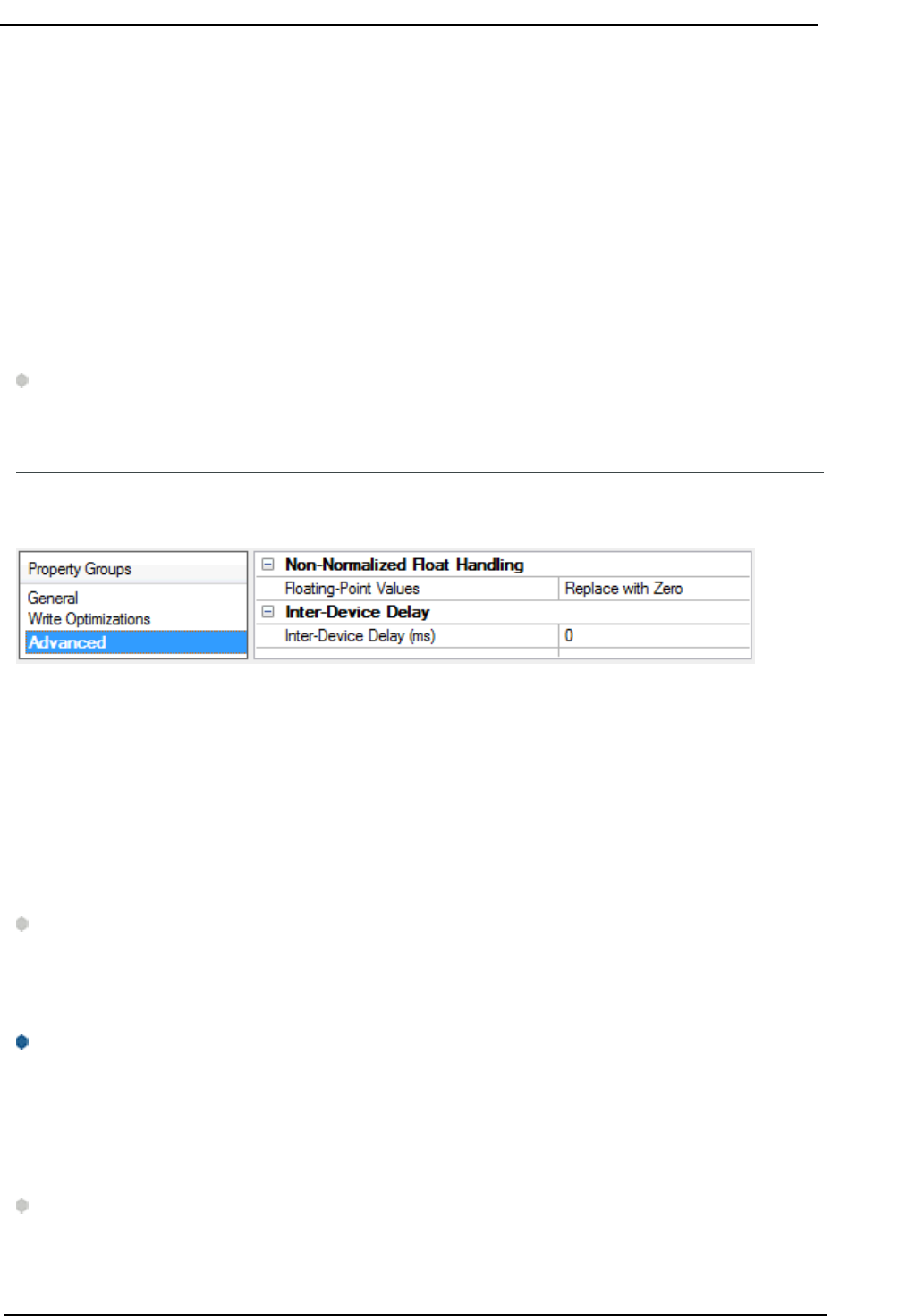
Channel Properties — Advanced
This group is used to specify advanced channel properties. Not all drivers support all properties; so the
Advanced group does not appear for those devices.
Non-NormalizedFloatHandling: A non-normalized value is defined as Infinity, Not-a-Number (NaN), or as
a Denormalized Number. The default is Replace with Zero. Drivers that have native float handling may
default to Unmodified. Non-normalized float handling allows users to specify how a driver handles non-nor-
malized IEEE-754 floating point data. Descriptions of the options are as follows:
l
Replace with Zero:This option allows a driver to replace non-normalized IEEE-754 floating point val-
ues with zero before being transferred to clients.
l
Unmodified:This option allows a driver to transfer IEEE-754 denormalized, normalized, non-num-
ber, and infinity values to clients without any conversion or changes.
Note:This property is disabled if the driver does not support floating-point values or if it only supports
the option that is displayed. According to the channel's float normalization setting, only real-time driver tags
(such as values and arrays) are subject to float normalization. For example, EFM data is not affected by this
setting.
For more information on the floating-point values, refer to "How To ... Work with Non-Normalized Floating-Point
Values" in the server help.
Inter-Device Delay: Specify the amount of time the communications channel waits to send new requests to
the next device after data is received from the current device on the same channel. Zero (0) disables the
delay.
Note:This property is not available for all drivers, models, and dependent settings.
www. ptc.com
8

Torque Tool Ethernet Driver
Device Properties — General
A device represents a single target on a communications channel. If the driver supports multiple controllers,
users must enter a device ID for each controller.
Identification
Name:Specify the name of the device. It is a logical user-defined name that can be up to 256 characters
long and may be used on multiple channels.
Note: Although descriptive names are generally a good idea, some OPC client applications may have a
limited display window when browsing the OPC server's tag space. The device name and channel name
become part of the browse tree information as well. Within an OPC client, the combination of channel name
and device name would appear as "ChannelName.DeviceName".
For more information, refer to "How To... Properly Name a Channel, Device, Tag, and Tag Group" in server help.
Description: Specify the user-defined information about this device.
Many of these properties, including Description, have an associated system tag.
Channel Assignment:Specify the user-defined name of the channel to which this device currently belongs.
Driver:Selected protocol driver for this device.
Model:Specify the type of device that is associated with this ID. The contents of the drop-down menu
depend on the type of communications driver being used. Models that are not supported by a driver are dis-
abled. If the communications driver supports multiple device models, the model selection can only be
changed when there are no client applications connected to the device.
Note:If the communication driver supports multiple models, users should try to match the model selec-
tion to the physical device. If the device is not represented in the drop-down menu, select a model that con-
forms closest to the target device. Some drivers support a model selection called "Open," which allows
users to communicate without knowing the specific details of the target device. For more information, refer to
the driver documentation.
ID:Specify the device's driver-specific station or node. The type of ID entered depends on the com-
munications driver being used. For many communication drivers, the ID is a numeric value. Drivers that sup-
port a Numeric ID provide users with the option to enter a numeric value whose format can be changed to
suit the needs of the application or the characteristics of the selected communications driver. The format is
set by the driver by default. Options include Decimal, Octal, and Hexadecimal.
Note: If the driver is Ethernet-based or supports an unconventional station or node name, the device's
TCP/IP address may be used as the device ID. TCP/IP addresses consist of four values that are separated by
periods, with each value in the range of 0 to 255. Some device IDs are string based. There may be additional
properties to configure within the ID field, depending on the driver.
www. ptc.com
9
Torque Tool Ethernet Driver
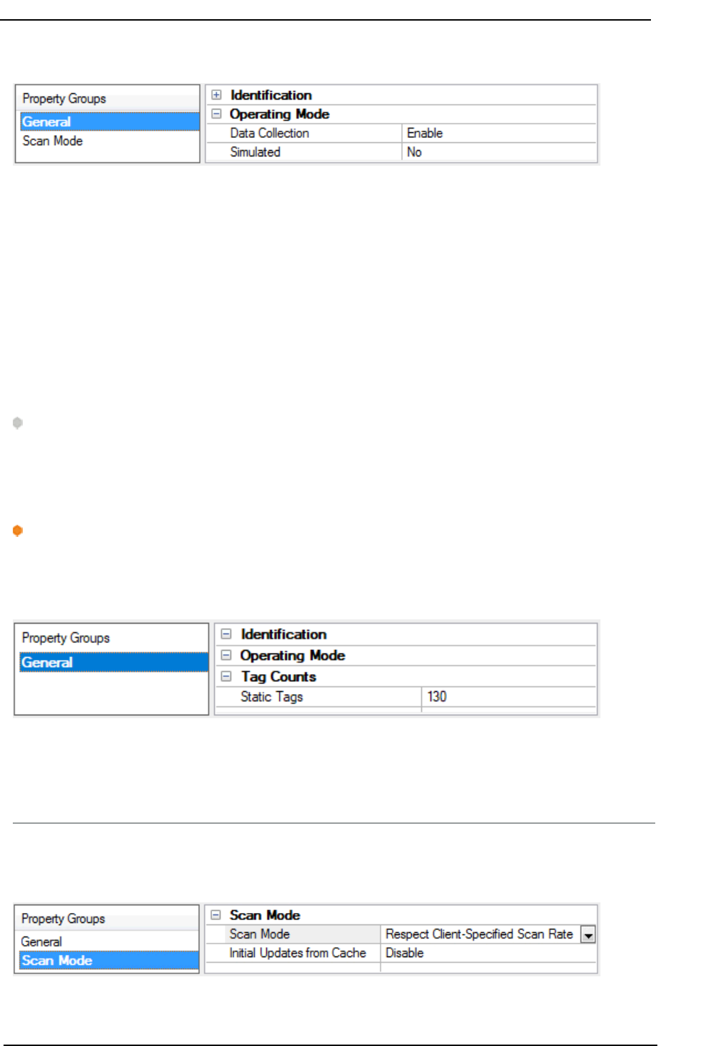
Operating Mode
Data Collection:This property controls the device's active state. Although device communications are
enabled by default, this property can be used to disable a physical device. Communications are not attemp-
ted when a device is disabled. From a client standpoint, the data is marked as invalid and write operations
are not accepted. This property can be changed at any time through this property or the device system tags.
Simulated:Place the device into or out of Simulation Mode. In this mode, the driver does not attempt to
communicate with the physical device, but the server continues to return valid OPC data. Simulated stops
physical communications with the device, but allows OPC data to be returned to the OPC client as valid data.
While in Simulation Mode, the server treats all device data as reflective: whatever is written to the simulated
device is read back and each OPC item is treated individually. The data is not saved if the server removes
the item (such as when the server is reinitialized). The default is No.
Notes:
1. This System tag (_Simulated) is read only and cannot be written to for runtime protection. The Sys-
tem tag allows this property to be monitored from the client.
2. When a device is simulated, updates may not appear faster than one (1) second in the client.
Simulation Mode is for test and simulation purposes only. It should never be used in a production envir-
onment.
Tag Counts
Static Tags:Provides the total number of defined static tags at this level (device or channel). This inform-
ation can be helpful in troubleshooting and load balancing.
Device Properties — Scan Mode
The Scan Mode specifies the subscribed-client requested scan rate for tags that require device com-
munications. Synchronous and asynchronous device reads and writes are processed as soon as possible;
unaffected by the Scan Mode properties.
www. ptc.com
10
Torque Tool Ethernet Driver
Scan Mode: Specify how tags in the device are scanned for updates sent to subscribing clients. Descriptions
of the options are:
l
Respect Client-Specified Scan Rate:This mode uses the scan rate requested by the client.
l
Request Data No Faster than Scan Rate:This mode specifies the value set as the maximum scan
rate. The valid range is 10 to 99999990 milliseconds. The default is 1000 milliseconds.
Note:When the server has an active client and items for the device and the scan rate value is
increased, the changes take effect immediately. When the scan rate value is decreased, the changes
do not take effect until all client applications have been disconnected.
l
Request All Data at Scan Rate:This mode forces tags to be scanned at the specified rate for sub-
scribed clients. The valid range is 10 to 99999990 milliseconds. The default is 1000 milliseconds.
l
Do Not Scan, Demand Poll Only:This mode does not periodically poll tags that belong to the
device nor perform a read to get an item's initial value once it becomes active. It is the OPC client's
responsibility to poll for updates, either by writing to the _DemandPoll tag or by issuing explicit
device reads for individual items. For more information, refer to "Device Demand Poll" in server help.
l
Respect Tag-Specified Scan Rate:This mode forces static tags to be scanned at the rate specified
in their static configuration tag properties. Dynamic tags are scanned at the client-specified scan
rate.
Initial Updates from Cache: When enabled, this option allows the server to provide the first updates for
newly activated tag references from stored (cached) data. Cache updates can only be provided when the
new item reference shares the same address, scan rate, data type, client access, and scaling properties. A
device read is used for the initial update for the first client reference only. The default is disabled; any time a
client activates a tag reference the server attempts to read the initial value from the device.
Device Properties — Timing
The device Timing properties allow the driver's response to error conditions to be tailored to fit the applic-
ation's needs. In many cases, the environment requires changes to these properties for optimum per-
formance. Factors such as electrically generated noise, modem delays, and poor physical connections can
influence how many errors or timeouts a communications driver encounters. Timing properties are specific
to each configured device.
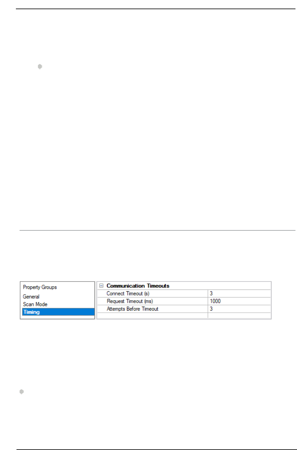
Communications Timeouts
Connect Timeout:This property (which is used primarily by Ethernet based drivers) controls the amount
of time required to establish a socket connection to a remote device. The device's connection time often
takes longer than normal communications requests to that same device. The valid range is 1 to 30 seconds.
The default is typically 3 seconds, but can vary depending on the driver's specific nature. If this setting is not
supported by the driver, it is disabled.
Note: Due to the nature of UDP connections, the connection timeout setting is not applicable when com-
municating via UDP.
Request Timeout:Specify an interval used by all drivers to determine how long the driver waits for a
response from the target device to complete. The valid range is 50 to 9999999 milliseconds (167 minutes).
The default is usually 1000 milliseconds, but can vary depending on the driver. The default timeout for most
www. ptc.com
11
Torque Tool Ethernet Driver
serial drivers is based on a baud rate of 9600 baud or better. When using a driver at lower baud rates,
increase the timeout to compensate for the increased time required to acquire data.
Attempts Before Timeout:Specify how many times the driver issues a communications request before
considering the request to have failed and the device to be in error. The valid range is 1 to 10. The default is
typically 3, but can vary depending on the driver's specific nature. The number of attempts configured for
an application depends largely on the communications environment. This property applies to both con-
nection attempts and request attempts.
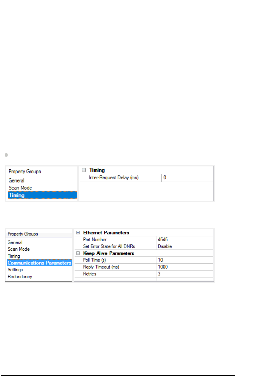
Timing
Inter-Request Delay: Specify how long the driver waits before sending the next request to the target
device. It overrides the normal polling frequency of tags associated with the device, as well as one-time
reads and writes. This delay can be useful when dealing with devices with slow turnaround times and in
cases where network load is a concern. Configuring a delay for a device affects communications with all
other devices on the channel. It is recommended that users separate any device that requires an inter-
request delay to a separate channel if possible. Other communications properties (such as communication
serialization) can extend this delay. The valid range is 0 to 300,000 milliseconds; however, some drivers may
limit the maximum value due to a function of their particular design. The default is 0, which indicates no
delay between requests with the target device.
Note: Not all drivers support Inter-Request Delay. This setting does not appear if it is not available.
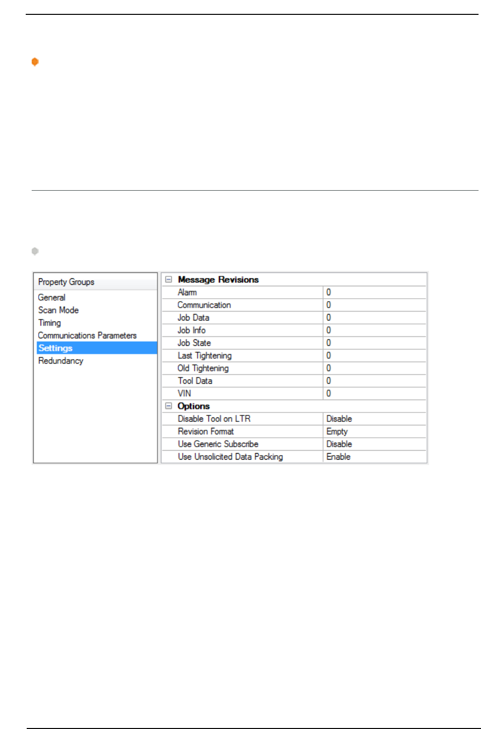
Device Properties — Communications Parameters
Ethernet Parameters
Port Number: Specify the port number that the driver will use when connecting to the device. The valid
range is 0 to 65535. For Open Protocol, the default setting is 4545. For FEP, the default setting is 9001.
Set Error State for All DNRs: When enabled, the driver will set the error state if the device does not
respond (DNR) to writes or subscription requests. The driver will always set the error state if the device does
not respond to reads. The default setting is disabled.
Keep-Alive Parameters
www. ptc.com
12
Torque Tool Ethernet Driver
Poll Time: Specify the amount of time of inactivity before the driver will send a Keep Alive message to the
device. The valid range is 1 to 15 seconds. The default setting is 10 seconds.
Caution: If the Keep Alive interval is set to a value greater than 10 seconds, the driver may post "Device
Not Responding" messages to the Event Log. This is because the device closes the connection.
Reply Timeout: Specify the amount of time that the driver will wait for a response from a Keep Alive mes-
sage. The valid range is 100 to 30000 milliseconds. The default setting is 1000 milliseconds (1 second).
Fail After: Specify the number of times that the driver will attempt to send a Keep Alive message before con-
sidering it to have failed. The valid range is 1 to 10. The default setting is 3.
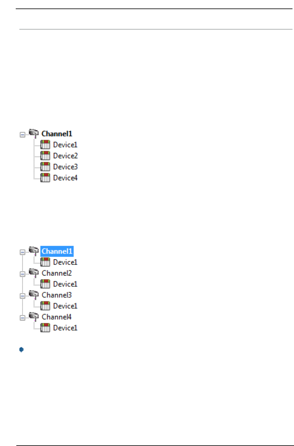
Device Properties — Settings
The Settings properties are used to request different revisions of messages from the device. To request a
specific message revision, enter the message revision number for that message. If the device does not sup-
port revisions, enter 0.
Note: The FEPmodel does not support message revisions, and will disable these options.
Message Revisions
Alarm: Specify the revision number for alarm messages. Supported values are 0 to 3, with 0 as the default.
This affects MIDs 0070 through 0078.
Communication: Specify the revision number for communication messages. Supported values are 0 to 6,
with 0 as the default. This affects MIDs 0001 and 0002.
Job Data: Specify the revision number for job data messages. Supported values are 0 to 3, with 0 as the
default. This affects MIDs 0032 and 0033.
Job Info: Specify the revision number for job info messages. Supported values are 0 to 4, with 0 as the
default. This affects MIDs 0034 through 0037.
Job State: Specify the revision number for job ID upload, job select, and job restart messages. Supported
values are 0 to 2, with 0 as the default. This affects MIDs 0030, 0031, 0038, and 0039.
www. ptc.com
13

Torque Tool Ethernet Driver
Last Tightening: Specify the revision number for the last tightening results messages. Supported values are
0 to 5 and 999 (for low-bandwidth version), with 0 as the default. This affects MIDs 0060 through 0063.
Old Tightening: Specify the revision number for the old tightening results messages. Supported values are
0 to 7, with 0 as the default. This affects MIDs 0064 and 0065.
Selector Lights: Specify the revision number for the selector control light messages. Supported values are 0
to 2, with 0 as the default. This affects MIDs 0254 and 0255.
ToolData: Specify the revision number for the tool data results messages. Supported values are 0 to 5, with
0 as the default. This affects MIDs 0040 and 0041.
VIN: Specify the revision number for the vehicle identification number (VIN) messages. Supported values
are 0 to 2, with 0 as the default. This affects MIDs 0051 through 0054.
Options
Disable Tool On LTR: When enabled, the driver will disable the tool whenever a last tightening results (LTR)
message is received. This ensures that no LTR data is overwritten before the system has had time to process
it. The default setting is disabled.
Revision Format: Specify how the driver should format the revision number for commands that use the
default revision (revision 0). By default, when the driver sends a revision 0 message it leaves the revision
number blank. Some devices do not support this and require the revision number to be explicitly set. Set-
ting this to Zero or One forces the driver to use 0 or 1 for the revision number in the message.
Use Generic Subscribe: Newer devices may only support subscribing using the Generic Subscribe MID 8.
Enabling this property changes the driver to use MID 8 when subscribing data updates.
Use Unsolicited Data Packing: Specify if the driver should update all tags for a given command set at once
or update those tags individually at their specified scan rate.
Device Properties — Redundancy
Redundancy is available with the Media-Level Redundancy Plug-In.
Consult the website, a sales representative, or the user manual for more information.
www. ptc.com
14
Torque Tool Ethernet Driver
Optimizing Communications
The Torque Tool Ethernet Driver has been designed to provide the best performance with the least amount
of impact on the system's overall performance. While the driver is fast, there are a couple of guidelines that
can be used to control and optimize the application and gain maximum performance.
This server refers to communications protocols like Torque Tool Ethernet as a channel. Each channel
defined in the application represents a separate path of execution in the server. Once a channel has been
defined, a series of devices must then be defined under that channel. Each of these devices represents a
single Torque Tool controller from which data will be collected. While this approach to defining the applic-
ation will provide a high level of performance, it won't take full advantage of the Torque Tool Ethernet Driver
or the network. An example of how the application may appear when configured using a single channel is
shown below.
Each device appears under a single channel. In this configuration, the driver must
move from one device to the next as quickly as possible to gather information at
an effective rate. As more devices are added or more information is requested
from a single device, the overall update rate begins to suffer.
If the Torque Tool Ethernet Driver could only define one single channel, the example shown above would be
the only option available; however, the driver can define up to 1024 channels. Using multiple channels dis-
tributes the data collection workload by simultaneously issuing multiple requests to the network. An
example of how the same application may appear when configured using multiple channels to improve per-
formance is shown below.
Each device has now been defined under its own channel. In this configuration, a
single path of execution is dedicated to the task of gathering data from each
device. If the application has 1024 or fewer devices, it can be optimized exactly
how it is shown here.
The performance will improve even if the application has more devices. While
fewer devices may be ideal, the application will still benefit from additional chan-
nels. Although by spreading the device load across all channels will cause the
server to move from device to device again, it can now do so with far less devices
to process on a single channel.
Note: Some devices support only one Ethernet connection. For these devices, only one channel and
device should be configured.
www. ptc.com
15

Torque Tool Ethernet Driver
Data Types Description
The Torque Tool Ethernet Driver supports the following data types.
Data Type Description
Boolean Single bit
Word Unsigned 16-bit integer
Short* Signed 16-bit integer
DWord Unsigned 32-bit integer
Long* Signed 32-bit integer
String ASCII text string
Float 32-bit floating point value
Date* 64 bit date and time value
Double* 64-bit floating point value
*These types are not used natively, but are supported through conversion.
Note: All non-variable tags used in the driver have a fixed data type. Therefore, it is recommended that
users allow the driver to use the default data type for the point.
www. ptc.com
16

Torque Tool Ethernet Driver
Address Descriptions
The Torque Tool Ethernet Driver specifies addresses by the name of the item that will be addressed. It may
be optionally followed by a bit or index number. The syntax is ITEMNAME<.BIT/INDEX>, where:
l
ITEMNAME: The name of the item that will be addressed.
l
BIT/INDEX: The bit number for items using bit fields, or index for arrayed items. The bit/index is only
used for certain address items.
Important: Bits are 0-based, with 0 being the LSB. Array indices are 1-based, with 1 being the first item.
Unsolicited Data
Some of the command sets are sent unsolicited by the device. These command sets will not have data avail-
able until the device sends the data to the driver. All unsolicited command sets have a NEWDATA item,
which will be set to 1 when new data arrives. Users may then clear this flag back to 0 by writing any value to
it.
Message Revisions
Some commands have multiple message revisions which hardware may support. Some items are only avail-
able for certain message revisions. These items have been marked as being available in a certain message
revision. For example, an item marked with (Rev 2) is only available in message revision 2 or later. Some
messages also have a low-bandwidth version available and will be marked appropriately.
Variable Data
Instead of adding revisions to allow for more information to be sent, the Open Protocol specification sup-
ports Variable Data fields. These are dynamic results where any number of values are returned. Each Vari-
able Data field contains the information needed to describe that piece of data and can be uniquely
identified by specifying the Message ID (MID), the Parameter ID (PID), and the Step number. To allow access
to these values, the format of the tag addresses needs to be “MID”.”PID”.”Step”.Unit; where Step and Unit
are optional. If Unit is specified, the Unit value is returned as a numeric value that corresponds to different
unit types (as defined in the Open Protocol specification). For example, to get the Final Torque on a MT
Focus 6000, the tag address might be ‘1202.30237’. To get the units of that value, use this tag address:
‘1202.30237.Unit’. MID901 variable data tags (such as 901.30424) contain graph markers and their respect-
ive values for plotting within the curve data returned in MID900 messages. There are common PID values
and there are PID values that are specific to the device. Refer to the Open Protocol specification and the device
specific specification for more information.
Protocols
The Torque Tool Ethernet Driver supports the OpenProtocol model and the Ford Ethernet Protocol(FEP)
model. Each protocol supports a set of commands that have one or more items available for addressing.
Not all command sets are supported for each model. For more information, select a link from the list below.
Alarm
Auto-Disable Settings
Flash
Identifiers
Job Info
Job Number Data
Job Data
Last Tightening Results
www. ptc.com
17

Torque Tool Ethernet Driver
Multi Spindle Results
Old Tightening Results
Operation Result
Parameter Set Data
Parameter Set Numbers
Parameter Set Selected
Selector Messages
Time
Tool Data
Trace Curve Data Messages
User Data Messages
VIN
Message IDs
For more information on the Message IDs (MIDs) supported by each device model, refer to the table below.
Message ID Description Supported Models
0001 Start communication Open, FEP
0002 Start communication acknowledge Open, FEP
0003 Stop communication Open, FEP
0004 Command error Open, FEP
0005 Command accepted Open, FEP
0008 Generic Subscription Open
0010 Pset number upload request Open, FEP
0011 Pset number upload reply Open, FEP
0012 Pset data upload request Open, FEP
0013 Pset data upload reply Open, FEP
0014 Pset selected subscribe Open, FEP
0015 Pset selected telegram Open, FEP
0016 Pset selected telegram acknowledge Open, FEP
0017 Pset selected unsubscribe Open, FEP
0018 Selected Pset Open, FEP
0019 Set Pset batch size Open, FEP
0020 Reset Pset batch size Open, FEP
0030 Job numbers upload request Open, FEP
0031 Job numbers upload reply Open, FEP
0032 Job data upload request Open
0033 Job data upload response Open
0034 Job selected/info subscribe Open, FEP
0035 Job selected/info Open, FEP
0036 Job selected/info acknowledge Open, FEP
www. ptc.com
18

Torque Tool Ethernet Driver
Message ID Description Supported Models
0037 Job selected/info unsubscribe Open, FEP
0038 Job selected in PF3000 Open, FEP
0039 Job restart Open, FEP
0040 Tool data upload request Open, FEP
0041 Tool data upload reply Open, FEP
0042 Disable tool Open, FEP
0043 Enable tool Open, FEP
0050 VIN download request Open, FEP
0051 VINupload subscribe Open, FEP
0052 VIN number upload Open, FEP*
0053 VIN upload acknowledge Open, FEP
0054 VIN upload subscribe Open, FEP
0060 Last Tightening Result (LTR) subscribe Open, FEP
0061 LTRupload Open, FEP*
0062 LTR upload acknowledge Open, FEP
0063 LTR unsubscribe Open, FEP
0064 Old Tightening Results (OTR) upload request Open, FEP
0065 OTR upload reply Open, FEP*
0070 Alarm subscribe Open, FEP
0071 Alarm upload reply Open, FEP
0072 Alarm upload acknowledge Open, FEP
0073 Alarm unsubscribe Open, FEP
0074 Alarm acknowledge on Torque controller Open, FEP
0075 Alarm acknowledge on Torque controller acknowledge Open, FEP
0076 Alarm status Open, FEP
0077 Alarm status acknowledge Open, FEP
0080 Time upload request Open, FEP
0081 Time upload Open, FEP
0082 Set time in torque controller Open, FEP
0100 Multi-spindle result subscribe Open, FEP
0101 Multi-spindle result upload Open, FEP**
0102 Multi-spindle result upload acknowledge Open, FEP
0103 Multi-spindle result unsubscribe Open, FEP
0113 Flash green light tool Open, FEP
0127 Job Cancel Open, FEP
0128 Batch increment Open
0140 Dynamic Job Request Open
0200 Set external controlled relays Open
0210 Status externally monitored inputs subscribe Open
www. ptc.com
19

Torque Tool Ethernet Driver
Message ID Description Supported Models
0211 Status externally monitored inputs upload Open
0212 Status externally monitored inputs upload acknowledge. Open
0213 Status externally monitored inputs unsubscribe Open
0216 Relay function subscribe Open
0217 Relay function data Open
0218 Relay function acknowledge Open
0219 Relay function unsubscribe Open
0224 Set digital input function Open
0225 Reset digital input function Open
0240 User Data Download Open
0241 User Data Subscribe Open
0242 User Data Message Open
0254 Selector control green lights Open
0255 Selector control red lights Open
0400 Auto/man mode subscribe FEP
0401 Auto/man mode upload FEP
0402 Auto/man mode acknowledge FEP
0403 Auto/man mode unsubscribe FEP
0410 Auto disable setting request FEP
0411 Auto disable setting reply FEP
0900 Trace Curve Data Message Open
0901 Trace Plot Parameters Open
1201 Operation result overall data Open
1202 Operation result object data Open
2500 Tightening program message download Open
2501 Tightening program message upload Open
9999 Keep alive Open, FEP
*Only supports MID Revision 1 as indicated in Revision 4.62 of the FEP specification.
**Unlike Open protocol, FEP does not use batch size, batch counter, and batch status parameters.
Command Set: Alarm
The Alarm command set is used to receive alarm data. All items belonging to this command set use MID 70
(Alarm subscribe) for the subscription request. The device sends the data through MID 71 and MID 76,
which are acknowledged with MID 72 and MID 77, respectively.
Item Data
Type
Access Description Data Range
ALARM_STATUS Boolean Read Only
0 if no alarm is active, 1 if an alarm is
currently active*
0-1
ALARM_ERROR String Read Only Error code 4 characters,
www. ptc.com
20

Torque Tool Ethernet Driver
Item Data
Type
Access Description Data Range
5 characters (Rev
2)
ALARM_C_READY Boolean Read Only Controller ready status:
1 = OK
0 = NOK
0-1
ALARM_T_READY Boolean Read Only Tool ready status:
1 = OK
0 = NOK
0-1
ALARM_TIME String Read Only Timestamp 19 characters
ALARM_NEWDATA Boolean Read/Write New data flag. Set to 1 when new data
arrives. Write a 0 to this flag to clear it.
0-1
ALARM_T_HEALTH Word,
Short
Read Only (Rev 3) Reports the tool status:
0 = Not Applicable
1 = OK
2 = NOK
0-2
ALARM_TEXT String Read Only (Rev 3) The text assigned to the alarm. 50 characters
*The ALARM_STATUS flag is valid on an initial connection to the device. Any subsequent alarm messages
after the initial update set the quality of the tag to "Bad" because the status is no longer provided by the
device.
Command Set: Auto-Disable Settings
The Auto-Disable Settings command set is only supported by the FEPmodel.
Item Data
Type
Access Description Data Range
AD_SETTING
Word,
Short
Read Only
Auto-Disable setting. AD_SETTING and
AD_BATCH data is retrieved using MID
410 (AutoDisable settings request) for
the request, which is replied to with
MID 411 (AutoDisable settings reply)
0-99
AD_BATCH Word,
Short
Read Only Current batch 0-99
AM_MODE Boolean Read Only Automatic/Manual mode. AM_MODE
uses MID 400 (Automatic/Manual mode
subscribe) for the subscription request.
The device sends the data through MID
401(Automatic/Manual mode), which is
replied to by MID 402 (Auto-
matic/Manual mode acknowledge).
0 = Automatic Mode
1 = ManualMode
2-10
AM_NEWDATA Boolean Read/Write New data flag. Set to 1 when new data 0-1
www. ptc.com
21

Torque Tool Ethernet Driver
Item Data
Type
Access Description Data Range
arrives. Write a 0 to this flag to clear it.
Command Set: Communication
The Communication command set is used to get information about the controller.
Item Data
Type
Access Description Data Range
COMM_CELL_ID Word,
Short
Read
Only
The cell ID of the controller 0-9999
COMM_CHANNEL_
ID
Word,
Short
Read
Only
The channel ID of the controller 0-20
COMM_CLIENT_ID Word,
Short
Read
Only
(Rev 2) The client ID 0-9
COMM_CONTROL_
NAME
String Read
Only
The name of the controller 25 characters
COMM_CONTROL_
SER_NUM
String Read
Only
(Rev 4) The serial number of the con-
troller
10 characters
COMM_CONTROL_
SOFT_VER
String Read
Only
(Rev 3) The controller software version 19 characters
COMM_LINK_
SUPPORT
Word,
Short
Read
Only
(Rev 6) Specifies that linking handling is
supported if 1
1
COMM_
PROTOCOL_
VERSION
String Read
Only
(Rev 3) The Open Protocol version sup-
ported by the controller's current firm-
ware
19 characters
COMM_RBU_TYPE String Read
Only
(Rev 4) The rapid backup unit (RBU) type 24 characters
COMM_SEO_NUM_
SUPPORT
Word,
Short
Read
Only
(Rev 6) Specifies that sequence number
handling is supported if 1
1
COMM_STATION_
ID
DWord,
Long
Read
Only
(Rev 6) The station ID or cell ID of the
controller
0-4294967295
COMM_STATION_
NAME
String Read
Only
(Rev 6) The station name of cell name of
the controller
25 characters
COMM_SUPPLIER_
CODE
String Read
Only
(Rev 2) The 3-character supplier code for
the controller
3 characters
COMM_SYS_
SUBTYPE
Word,
Short
Read
Only
(Rev 5) The system subtype of the con-
troller
0-2
COMM_SYS_TYPE Word,
Short
Read
Only
(Rev 5) The system type of the controller:
0 = System type not set
1 = Power Focus 4000
2 = Power MACS 4000
3 = Power Focus 6000
0-999
COMM_TOOL_
SOFT_VER
String Read
Only
(Rev 3) The tool software version 19 characters
www. ptc.com
22

Torque Tool Ethernet Driver
Command Set: Dynamic Job Request
The dynamic job request command set requests a dynamic job to be executed, which is immediately
executed (if possible) by the controller but not saved in the controller memory. A dynamic job lifetime is the
time for the job to be executed. If the controller is powered off before the completion of the job, the
dynamic job is lost. The message is sent using MID 140.
Item Data
Type
Access Description
DYNAMIC_JOB_REQUEST String Write
Only
Passes the message to the device with the string
written as a message payload
See Also: Appendix — Dynamic Job Request, Reference the Torque Tool Open Protocol Specification for fur-
ther information.
Command Set: Flash
The Flash command set is used to cause the tool's green light to flash.
Item Data
Type
Access Description Data Range
FLASH Boolean Write
Only
Write any value to this item to cause the
green light on the tool to flash until an
operator pushes the tool trigger. FLASH
uses MID 113 (Flash green light on tool).
N/A
Command Set: Identifiers
The Identifiers command set is used to manage the multiple identifiers in the controller. It is only supported
by the Open Protocol model. All tags prefixed by MID_ are subscription based and use MID 151 (Multiple
identifiers work order subscribe) for the subscription request. The device sends the item data to the server
through MID 152 (Multiple Identifiers work order), which the server responds to with MID 153 (Multiple Iden-
tifiers work order acknowledge).
Item Data
Type
Access Description Data Range
ID_DOWNLOAD String Write Only Write the identifiers to this item to send
the identifiers to the controller. ID_
DOWNLOAD uses MID 150 (Identifier
download request) to send the identifier
that was written to the item to the con-
troller.
100 characters
ID_BYPASS Boolean Write Only Write any value to this item to bypass
the next identifier expected in the work
order. ID_BYPASS uses MID 155 (Bypass
Identifier) to bypass the next identifier
expected in the work order.
N/A
ID_RESET Boolean Write Only Write any value to this item to reset the N/A
www. ptc.com
23

Torque Tool Ethernet Driver
Item Data
Type
Access Description Data Range
latest identifier or bypassed identifier in
the work order. ID_RESET uses MID 156
(Reset latest Identifier) to reset the
latest identifier or bypassed identifier in
the work order.
ID_RESETALL Boolean Write Only Write any value to this item to reset all
identifiers in the work order. ID_
RESETALL uses MID 157 (Reset all Iden-
tifiers) to reset all identifiers in the cur-
rent work order.
N/A
MID_TYPE Word,
Short
Read Only Identifier type number* 1-4
MID_IN_ORDER Boolean Read Only Included in work order*
0 = No
1 = Yes
0-1
MID_STATUS Word,
Short
Read Only Status in work order*
0 = Not accepted
1 = Accepted
2 = Bypassed
3 = Reset
0-3
MID_ID String Read Only Identifier* 25 characters
MID_NEWDATA Boolean Read/Write New data flag. Set to 1 when new data
arrives. Write a 0 to this flag to clear it.
N/A
*These items require an array index (1..4).
Command Set: IO Interface
The IOInterface command set is used to control external IO devices connected to the Torque Tool device.
The driver sends the Relay Function data subscription request through MID 216. After subscription, the
device sends item data to the driver using MID 217 and the driver acknowledges receipt of the item data
using MID 218. MID 219 is used by the driver to unsubscribe to Relay Function data, typically as client ref-
erences to Relay Function tags are removed from the server.
Item Data
Type
Access Description Data Range
RESET_DIGITAL_
INPUT
Word,
Short
Write
Only
Resets the digital input function with the
entered digital input value using MID
225. These values are device specific.
Refer to the device documentation for
more information.
0-999
RELAY_
FUNCTION.#
Word,
Short
Read
Only
Allows the user to get relay information
for the first 500 (0-499) functions defined
on the controller.
0, 1
www. ptc.com
24

Torque Tool Ethernet Driver
Item Data
Type
Access Description Data Range
Refer to the controller documentation to
determine which relay number corresponds
to what relay function.
Values received are:
0 = Not Active
1 = Active
Note: The server only supports relays
that are Tracking Events; events where
the value changes based on a condition.
SET_DIGITAL_
INPUT
Word,
Short
Write
Only
Sets the digital input function with the
entered digital input value using MID
224. These values are device specific.
Refer to the device documentation for
more information.
0-999
STATUS_RELAY_# Word,
Short
Write
Only
Set "external controlled" relays
Write to this item to set the status of the
corresponding external relay number. All
other relays are sent a '3'.
0 = Off
1 = On (fast)
2 = Flashing
3 = Keep the same results
STATUS_RELAY_# tags use MID 200 (Set
externally controlled relays) to set indi-
vidual relay statuses.
0-3
STATUS_DIGIN_# Boolean Read
Only
Get "external controlled" digital input
statuses
This item uses an unsolicited command
set to get the current status of all digital
inputs whenever one of them change.
The valid DigIn range is 1-8.
0 = Off
1 = On
STATUS_DIGIN_# tags use MID 210
(Status externally monitored inputs sub-
scribe) to subscribe to individual digital
input statuses, the data is sent from the
device to the server using MID 211
(Status externally monitored inputs).
0, 1
www. ptc.com
25

Torque Tool Ethernet Driver
Command Set: Job Info
The Job Info command set is used to receive data on the selected job, to allow the user to select a different
job, and to control job execution.
JOB_JOBNUM uses MID 38 (Select Job) to set the current job, JOB_RESTART uses MID 39 (Job restart) to
restart a job, JOB_ABORT uses MID 127 (cancel job) to terminate the current job. All other tags use MID 34
(Job info subscribe) to subscribe to job info. The device sends job info to the server using MID 35 (Job info),
which is responded to with MID 36 (Job info acknowledge). If the device supports 4-digit Job IDs, revision 2
or higher must be used.
Note: Some command set items also have alias names. In the table below, the alias name will be listed
beneath the item where applicable.
Item Data
Type
Access Description Data Range
JOB_JOBNUM
LINK_LINKNUM
Word,
Short
Read/Write The selected job number. To select a
different job, write a job number to this
item.
0-99 (Rev 1)
0-9999 (Rev 2+)
JOB_STATUS*
LINK_STATUS*
Word,
Short
Read Only Job batch status
0 = Job batch not completed
1 = Job batch OK
2 = Job batch NOK
0-2
JOB_BMODE*
LINK_BMODE*
Word,
Short
Read Only Job batch mode
0 = Only the OK bolts are counted
1 = Both the OK and the NOK bolts are
counted
0-1
JOB_BSIZE*
LINK_BSIZE*
Word,
Short
Read Only Job batch size 0-9999
JOB_BCOUNT*
LINK_BCOUNT*
Word,
Short
Read Only Job batch counter 0-9999
JOB_TIME*
LINK_TIME*
String Read Only Timestamp for the job info 19 characters
JOB_STEP* Word,
Short
Read Only The current step the job is on. 0-999 (Rev 3 and
4**)
JOB_SCOUNT* Word,
Short
Read Only The number of steps in the job. 0-999 (Rev 3 and
4**)
JOB_STYPE* Word,
Short
Read Only The step type
1 = Batch Step
2-6 = Reserved
0-99 (Rev 3 and
4**)
JOB_TSTATUS* Word,
Short
Read Only The status of the job tightening:
0 = JobTight OFF
1 = JobTight OK
2 = JobTight NOK
3 = JobTight Terminated
4 = JobTight Incremented
5 = JobTight Decremented
6 = JobTight Bypassed
0-10 (Rev 4)
www. ptc.com
26

Torque Tool Ethernet Driver
Item Data
Type
Access Description Data Range
7 = JobTight Reset Batch
8 = JobTight Loosening
9 = JobTight Free Batch
10 = JobTight Job Terminated
JOB_NEWDATA
LINK_NEWDATA
Boolean Read/Write New data flag. Set to 1 when new data
arrives. Write a 0 to this flag to clear it.
0-1
JOB_RESTART
LINK_RESTART
Word,
Short
Write Only Write a job number to this item to
restart that job
0-99 (Rev 1)
0-9999 (Rev 2)
JOB_ABORT
LINK_ABORT
Boolean Write Only Write any value to this item to ter-
minate the current job
N/A
JOB_BATCH_
INCREMENT*
Boolean Write Only Write any value to this item to incre-
ment the batch number
N/A
*This item is only supported by the Open Protocol model.
** This tag may not be valid for some devices when using revision 4.
Consult device documentation for supported MIDs and data fields.
Command Set: Job Data
The Job Data command set is used to request the configuration of a specific job. To request a job, write the
Job ID to JOBDATA_JOBID. All items belonging to this comment set use MID 32 (Job Data Upload Request) to
request the data, which is replied to with MID 33 (Job Data Upload Reply). If the device supports 4 digits Job
IDs, revision 2 or higher must be used.
Item Data
Type
Access Description Data Range
JOBDATA_JOBID Word,
Short
Read/Write Write a Job ID to this item to request
the job’s configuration
0-9999
JOBDATA_NAME String Read Only The name of job 25 characters
JOBDATA_
FORCED_ORDER
Word,
Short
Read Only Forced Order
0 = Free Order
1 = Forced Order
2 = Free and Forced
0-2
JOBDATA_MAX_
FIRST_
TIGHTENING_TIME
Word,
Short
Read Only Maximum time for first tightening 0-9999
JOBDATA_MAX_
COMPLETION_
TIME
DWord,
Long
Read Only Maximum time to complete the job 0-99999
JOBDATA_BATCH_
MODE
Word,
Short
Read Only Job batch mode/batch count type
0 = Only the OK tightenings are coun-
ted
1 = Both OK and NOK tightenings are
counted
0-1
JOBDATA_LOCK_ Boolean Read Only Lock at Job done True/False
www. ptc.com
27

Torque Tool Ethernet Driver
Item Data
Type
Access Description Data Range
ON_DONE True = Yes
False = No
JOBDATA_LINE_
CONTROL
Boolean Read Only Use line control
True = Yes
False = No
True/False
JOBDATA_REPEAT_
JOB
Boolean Read Only Repeat Job
True = Yes
False = No
True/False
JOBDATA_TOOL_
LOOSENING
Word,
Short
Read Only Tool loosening
0 = Enable
1 = Disable
2 = Enable only on NOK tightening
0-2
JOBDATA_TOOL_
RESERVED
Word,
Short
Read Only Reserved for Job repair 0-1
JOBDATA_
PARAMETER_
CHANNEL_ID
Word,
Short*
Read Only The parameter’s Channel ID 0-99
JOBDATA_
PARAMETER_TYPE_
ID
Word,
Short*
Read Only The parameter’s Type ID 0-999
JOBDATA_
PARAMETER_
AUTO_VALUE
Boolean* Read Only The parameter’s Auto Value True/False
JOBDATA_
PARAMETER_
BATCH_SIZE
Word,
Short*
Read Only The parameter’s batch size 0-99
JOBDATA_
PARAMETER_
COUNT
Word,
Short
Read Only The number of parameters in the job 0-99 (Rev 3)
JOBDATA_
PARAMETER_
SOCKET
Word,
Short*
Read Only The parameter’s socket number 0-99 (Rev 3)
JOBDATA_
PARAMETER_STEP_
NAME
String* Read Only The parameter’s step name 25 characters (Rev
3)
JOBDATA_
PARAMETER_STEP_
TYPE
Word,
Short*
Read Only The parameter’s step type 0-99 (Rev 3)
*This item requires an array index or bit index. The valid array / bit index range is 1 to 99.
www. ptc.com
28

Torque Tool Ethernet Driver
Command Set: Job Number Data
The Job Number Data command set is used to request generic job data on the controller. Some command
set items also have alias names. In the table below, the alias name will be listed beneath the item where
applicable. All items belonging to this command set use MID 30 (Job ID upload request) for requesting the
item data, which is replied to with MID 31 (Job ID upload reply). If the device supports 4-digit Job IDs, revi-
sion 2 or higher must be used.
Item Data
Type
Access Description Data Range
JOBN_COUNT
LINKN_COUNT
Word,
Short
Read
Only
Count of the number of valid jobs 0-99 (Rev 1)
0-9999 (Rev 2)
JOBN_ID
LINKN_ID
Word,
Short*
Read
Only
Valid job numbers (the number available
is specified by JOBN_COUNT)
0-99 (Rev 1)
0-9999 (Rev 2)
*This item requires an array index or bit index. The valid array / bit index range is 1 to 9999.
Command Set: Last Tightening Results
The Last Tightening Results command set is used to receive data for the last tightening. All items belonging
to this command set use MID 60 (Last tightening result data subscribe) for the subscription request. The
device sends the data through MID 61 (Last tightening result data), which is replied to by MID 62 (Last tight-
ening result acknowledge).
Item Data
Type
Access Description Data Range
LTR_CELL_ID Word,
Short
Read Only Cell ID 0-9999
LTR_CHAN_ID Word,
Short
Read Only Channel ID 0-99
LTR_TC_NAME String Read Only Torque controller name 25 characters
LTR_VIN String Read Only Vehicle ID number* 25 characters
LTR_JOB Word,
Short
Read Only Job number* 0-99 (Rev 1)
0-9999
(Rev 2+)
LTR_PSET Word,
Short
Read Only PSet number* 0-999
LTR_BATCH_SIZE Word,
Short
Read Only Batch size* 0-9999
LTR_BATCH_
COUNTER
Word,
Short
Read Only Batch counter* 0-9999
LTR_TIGHT_
STATUS
Word,
Short
Read Only Tightening status*
0 = NOK
1 = OK
0-1
LTR_TORQUE_
STATUS
Word,
Short
Read Only Torque status*
0 = Low
1 = OK
0-2
www. ptc.com
29

Torque Tool Ethernet Driver
Item Data
Type
Access Description Data Range
2 = High
LTR_ANGLE_
STATUS
Word,
Short
Read Only Angle status*
0 = Low
1 = OK
2 = High
0-2
LTR_TORQUE_MIN Float Read Only Torque minimum limit 0-9999.99
LTR_TORQUE_MAX Float Read Only Torque maximum limit 0-9999.99
LTR_TORQUE_
TARGET
Float Read Only Torque final target 0-9999.99
LTR_TORQUE_
VALUE
Float Read Only Torque value* 0-9999.99
LTR_ANGLE_MIN DWord Read Only Angle minimum value, in degrees 0-99999
LTR_ANGLE_MAX DWord Read Only Angle maximum value, in degrees 0-99999
LTR_ANGLE_
TARGET
DWord,
Long
Read Only Target angle value, in degrees 0-99999
LTR_ANGLE_VALUE DWord,
Long
Read Only Turning angle value, in degrees* 0-99999
LTR_TIMESTAMP String Read Only Timestamp* 19 characters
LTR_CHANGETIME String Read Only Last change in PSet settings* 19 characters
LTR_BATCH_
STATUS
Word,
Short
Read Only Batch status*
0 = NOK
1 = OK
2 = Batch not used
0-2
LTR_ID DWord,
Long
Read/Write** Tightening ID* 0-4294967295
LTR_STRATEGY Word,
Short
Read Only (Rev 2) Strategy
1 = Torque control
2 = Torque control / angle monitoring
3 = Torque control / angle control
AND
4 = Angle control / torque monitoring
5 = DS control
6 = DS control torque monitoring
7 = Reverse angle
8 = Reverse torque
9 = Click wrench
10 = Rotate spindle forward
11 = Torque control angle control OR
12 = Rotate spindle reverse
99 = No strategy
0-99
LTR_STRAT_OPT Boolean Read Only (Rev 2) Strategy options
This item requires a bit number (0-15)
0-1
www. ptc.com
30

Torque Tool Ethernet Driver
Item Data
Type
Access Description Data Range
Bit 0 = Torque
Bit 1 = Angle
Bit 2 = Batch
Bit 3 = PVT monitoring
Bit 4 = PVT compensate
Bit 5 = Selftap
Bit 6 = Rundown
Bit 7 = CM
Bit 8 = DS control
Bit 9 = Click wrench
Bit 10 = RBW monitoring
LTR_RDA_STATUS Word,
Short
Read Only (Rev 2) Rundown angle status
0 = NOK
1 = OK
2 = High
0-2
LTR_CMON_
STATUS
Word,
Short
Read Only (Rev 2) Current monitoring status
0 = NOK
1 = OK
2 = High
0-2
LTR_ST_STATUS Word,
Short
Read Only (Rev 2) Selftap status
0 = NOK
1 = OK
2 = High
0-2
LTR_PTM_STATUS Word,
Short
Read Only (Rev 2) Prevail torque monitoring
status
0 = NOK
1 = OK
2 = High
0-2
LTR_PTC_STATUS Word,
Short
Read Only (Rev 2) Prevail torque compensate
status
0 = NOK
1 = OK
2 = High
0-2
LTR_PVT Float Read Only (Rev 6) PVT compensation value 0-99999.99
LTR_TERR_STATUS Boolean Read Only (Rev 2) Tightening error status
This item requires a bit number (0-31)
Bit 0 = Rundown angle max shut off
Bit 1 = Rundown angle min shut off
Bit 2 = Torque max shut off
Bit 3 = Angle max shut off
Bit 4 = Selftap torque max. shut off
Bit 5 = Selftap torque min. shut off
Bit 6 = Prevail torque max. shut off
0-1
www. ptc.com
31

Torque Tool Ethernet Driver
Item Data
Type
Access Description Data Range
Bit 7 = Prevail torque min. shut off
Bit 8 = Prevail torque compensate
overflow
Bit 9 = Current monitoring max shut
off
Bit 10 = Post view torque min. torque
shut off
Bit 11 = Post view torque max. torque
shut off
Bit 12 = Post view torque angle too
small
Bit 13 = Trigger lost
Bit 14 = Torque less than target
Bit 15 = Tool hot
Bit 16 = Multistage cancel
Bit 17 = Rehit
Bit 18 = DS measure failed
Bit 19 = Current limit reached
Bit 20 = End time out shutoff
Bit 21 = Remove fastener limit
exceeded
Bit 22 = Disable drive
LTR_TERR_
STATUS_
COMBINED
DWord,
Long
Read Only (Rev 2) All tightening error status bits
are combined in one value. Refer to
LTR_TERR_STATUS to review the match
of each bit and the value.
0 to 4294967295
(DWord)
-2,147,483,648 to
2,147,483,647
(Long)
LTR_TERR_
STATUS2
Boolean Read Only (Rev 6) Tightening error status 2
This item requires a bit number (0-31)
Bit 0 = Drive deactivated
Bit 1 = Tool stall
Bit 2 = Drive hot
Bit 3 = Gradient monitoring high
Bit 4 = Gradient monitoring low
Bit 5 = Reaction bar failed
Bit 6 - 31 = Reserved
0-1
LTR_TERR_
STATUS2_
COMBINED
DWord,
Long
Read Only (Rev 6) All tightening error status 2
bits are combined in one value. Refer
to LTR_TERR_STATUS2 to review the
match of each bit and the value.
0 to 4294967295
(DWord)
-2,147,483,648 to
2,147,483,647
(Long)
LTR_RDA_MIN DWord,
Long
Read Only (Rev 2) Rundown angle minimum
value, in degrees
0-99999
LTR_RDA_MAX DWord,
Long
Read Only (Rev 2) Rundown angle maximum
value, in degrees
0-99999
www. ptc.com
32

Torque Tool Ethernet Driver
Item Data
Type
Access Description Data Range
LTR_RDA_VALUE DWord,
Long
Read Only (Rev 2) Rundown angle value
reached, in degrees
0-99999
LTR_CM_MIN Word,
Short
Read Only (Rev 2) Current monitoring minimum
limit
0-999
LTR_CM_MAX Word,
Short
Read Only (Rev 2) Current monitoring maximum
limit
0-999
LTR_CM_VALUE Word,
Short
Read Only (Rev 2) Current monitoring value in
percent
0-999
LTR_ST_MIN Float Read Only (Rev 2) Selftap minimum limit 0-9999.99
LTR_ST_MAX Float Read Only (Rev 2) Selftap maximum limit 0-9999.99
LTR_ST_TORQUE Float Read Only (Rev 2) Selftap torque. 0-9999.99
LTR_PTM_MIN Float Read Only (Rev 2) Prevail torque monitoring min-
imum limit
0-9999.99
LTR_PTM_MAX Float Read Only (Rev 2) Prevail torque monitoring
maximum limit
0-9999.99
LTR_PT Float Read Only (Rev 2) Prevail torque value 0-9999.99
LTR_JOB_SEQ_
NUM
Word,
Short
Read Only (Rev 2) Job sequence number 0-65535
LTR_STID Word,
Short
Read Only (Rev 2) Synch tightening ID 0-65535
LTR_SERIAL_NUM String Read Only (Rev 2) Tool serial number 14 characters
LTR_PSET_NAME String Read Only (Rev 3) Parameter set name 25 characters
LTR_UNITS Word,
Short
Read Only (Rev 3) Torque value units
1 = Nm
2 = Lbf.ft
3 = Lbf.In
4 = Kpm
1-4
LTR_RESULT_TYPE Word,
Short
Read Only (Rev 3) Result type
1 = Tightening
2 = Loosening
3 = Batch Increment
4 = Batch decrement
5 = Bypass Pset result
6 = Cancel job result
7 = Sync tightening
1-7
LTR_IDR2 String Read Only (Rev 4) Identifier result part 2 25 characters
LTR_IDR3 String Read Only (Rev 4) Identifier result part 3 25 characters
LTR_IDR4 String Read Only (Rev 4) Identifier result part 4 25 characters
LTR_CUSTOM_ERR String Read Only (Rev 5) Customer tightening error
code
4 characters
LTR_MULTISTAGE_
COUNT
Word Read Only (Rev 998) Number of run stages. For
each completed stage the final
torque and the final angle are repor-
0-99
www. ptc.com
33

Torque Tool Ethernet Driver
Item Data
Type
Access Description Data Range
ted.
LTR_MULTISTAGE_
ANGLE.N
Long*** Read Only (Rev 998) The turning angle stage
value in degrees. Each turn rep-
resents 360 degrees. ‘N’ is the stage
number in the tightening.
0-99999
LTR_MULTISTAGE_
TORQUE.N
Float*** Read Only (Rev 998) The stage torque value. ‘N’
is the stage number in the tightening.
0.0-999999.0
LTR_NEWDATA Boolean Read/Write New data flag. Set to 1 when new
data arrives. Write a 0 to this flag to
clear.
0-1
*These items are available in the low-bandwidth (revision 999) message.
**Writing any value to the Tightening ID will set the value in the driver to 0. This will not have any effect on
the hardware.
***These items require an array index or bit index. The valid array / bit index range is 1 to 99.
See Also: Appendix - LTR Revision 998 Tag Behavior for more information.
Note: Any commands that require special revisions (such as 2, 3, and so forth) are not supported by the
FEP Protocol model.
Command Set: Multi-Spindle Results
The Multiple Spindle Results command set can be used to receive data that includes tightening results for
tools that have multiple spindles. All items belonging to this command set use MID 100 (Multi-spindle result
subscribe) for the subscription request. The device sends the data through MID 101 (Multi-spindle result),
which is replied to by MID 102 (Multi-spindle result data acknowledge).
Item Data
Type
Access Description Data Range
MS_NUMBER
Word,
Short
Read Only Number of running spindles 2-10
MS_VIN String Read Only Vehicle ID number 25 characters
MS_JOBNUM Word,
Short
Read Only Job number (Link Group) 0-99
MS_PSET Word,
Short
Read Only Parameter set (App) 0-999
MS_BSIZE* Word,
Short
Read Only Batch size 0-9999
MS_BCOUNT* Word,
Short
Read Only Batch counter 0-9999
MS_BSTATUS*
Word,
Short
Read Only
Batch status
0 = NOK
1 = OK
www. ptc.com
34

Torque Tool Ethernet Driver
Item Data
Type
Access Description Data Range
2 = Batch not used
MS_TMIN Float Read Only Torque minimum limit 0-9999.99
MS_TMAX Float Read Only Torque maximum limit 0-9999.99
MS_TTARG Float Read Only Torque final target 0-9999.99
MS_AMIN
DWord,
Long
Read Only Angle minimum limit 0-99999
MS_AMAX
DWord,
Long
Read Only Angle maximum limit 0-99999
MS_ATARG
DWord,
Long
Read Only Angle final target 0-99999
MS_CHANGETIME String Read Only Last change in setting 19 characters
MS_TIME String Read Only Time stamp 19 characters
MS_SYNCID
DWord,
Long
Read Only Sync tightening ID 0-99999
MS_SYNCSTAT
Word,
Short
Read Only
Overall tightening status
0 = NOK
1 = OK
0-1
SPD_NUM**
Word,
Short
Read Only Spindle number 1-10
SPD_CHAN**
Word,
Short
Read Only Channel ID 1-20
SPD_STATUS**
Word,
Short
Read Only
Overall spindle status
0 = NOK
1 = OK
0-1
SPD_TSTATUS**
Word,
Short
Read Only
Individual torque status
0 = NOK
1 = OK
0-1
SPD_TORQUE** Float Read Only Individual torque 0-9999.99
SPD_ASTATUS**
Word,
Short
Read Only
Individual angle status
0 = NOK
1 = OK
0-1
SPD_ANGLE**
DWord,
Long
Read Only Individual angle 0-99999
MS_NEWDATA Boolean Read/Write
New data flag. Set to 1 when new data
arrives. Write a 0 to this flag to clear it.
0-1
*Although this was not supported by the Open protocol, the Torque Tool Ethernet Driver supports this fea-
ture. This feature is supported by prefixing the Address Item with the Spindle number delimited by a ':' (e.g.
01:VIN_VIN). For the Open protocol, the spindle data is ignored.
**This item requires an array index. The maximum array index is given by MS_Number.
www. ptc.com
35

Torque Tool Ethernet Driver
Command Set: Old Tightening Results
The Old Tightening Results command set is used to retrieve data for an old tightening result. To retrieve the
data for a tightening result, write the Tightening ID to the OTR_ID field. All items belonging to this command
set use MID 64 (Old tightening result upload request) for requesting the item data, which is replied to with
MID 65 (Old tightening result upload reply).
Item Data Type Access Description Data Range
OTR_ID DWord,
Long
Read /
Write
Tightening ID. Write the Tightening ID
to this item to retrieve data for that
tightening. Writing 0 will retrieve the
last tightening results.
0-4294967295
OTR_VIN String Read
Only
Vehicle ID number 25 characters
OTR_PSET Word, Short Read
Only
PSet number 0-999
OTR_BCOUNT Word, Short Read
Only
Batch counter 0-9999
OTR_TIGHTSTAT Word, Short Read
Only
Tightening status
0 = NOK
1 = OK
0-1
OTR_TORQSTAT Word, Short Read
Only
Torque Status
0 = Low
1 = OK
2 = High
0-2
OTR_ANGSTAT Word, Short Read
Only
Angle Status
0 = Low
1 = OK
2 = High
0-2
OTR_TORQUE Float Read
Only
Torque value 0-9999.99
OTR_ANGLE DWord,
Long
Read
Only
Turning angle value in degrees 0-99999
OTR_TIME String Read
Only
Timestamp 19 characters
OTR_BATSTAT Word, Short Read
Only
Batch status
0 = NOK
1 = OK
2 = Batch not used
0-2
OTR_JOBNUM Word, Short Read
Only
(Rev 2) Job number 0-9999
OTR_STRATEGY Word, Short Read
Only
(Rev 2) Strategy
1 = Torque control
2 = Torque control / angle monitoring
3 = Torque control / angle control AND
4 = Angle control / torque monitoring
-99
www. ptc.com
36

Torque Tool Ethernet Driver
Item Data Type Access Description Data Range
5 = DS control
6 = DS control torque monitoring
7 = Reverse angle
8 = Reverse torque
9 = Click wrench
10 = Rotate spindle forward
11 = Torque control angle control OR
12 = Rotate spindle reverse
99 = No strategy
OTR_STROPT Boolean Read
Only
(Rev 2) Strategy options
This item requires a bit number (0-15)
Bit 0 = Torque
Bit 1 = Angle
Bit 2 = Batch
Bit 3 = PVT Monitoring
Bit 4 = PVT Compensate
Bit 5 = Selftap
Bit 6 = Rundown
Bit 7 = CM
Bit 8 = DS Control
Bit 9 = Click Wrench
Bit 10 = RBW Monitoring
-1
OTR_BSIZE Word, Short Read
Only
(Rev 2) Batch size 0-9999
OTR_RASTAT Word, Short Read
Only
(Rev 2) Rundown angle status
0 = NOK
1 = OK
2 = High
0-2
OTR_CMSTAT Word, Short Read
Only
(Rev 2) Current monitoring status
0 = NOK
1 = OK
2 = High
-2
OTR_STSTAT Word, Short Read
Only
(Rev 2) Selftap status
0 = NOK
1 = OK
2 = High
0-2
OTR_PTMSTAT Word, Short Read
Only
(Rev 2) Prevail torque monitoring
status
0 = NOK
1 = OK
2 = High
0-2
OTR_PTCSTAT Word, Short Read
Only
(Rev 2) Prevail torque compensate
status
0 = NOK
1 = OK
2 = High
0-2
www. ptc.com
37

Torque Tool Ethernet Driver
Item Data Type Access Description Data Range
OTR_TERRSTAT Boolean Read
Only
(Rev 2) Tightening error status
This item requires a bit number (0-31):
Bit 0 = Rundown angle max shut off
Bit 1 = Rundown angle min shut off
Bit 2 = Torque max shut off
Bit 3 = Angle max shut off
Bit 4 = Selftap torque max shut off
Bit 5 = Selftap torque min shut off
Bit 6 = Prevail torque max shut off
Bit 7 = Prevail torque min shut off
Bit 8 = Prevail torque compensate
overflow
Bit 9 = Current monitoring max shut
off
Bit 10 = Post view torque min torque
shut off
Bit 11 = Post view torque max torque
shut off
Bit 12 = Post view torque Angle too
small
Bit 13 = Trigger Lost
Bit 14 = Torque Less Than Target
Bit 15 = Tool Hot
Bit 16 = Multistage Cancel
Bit 17 = Rehit
Bit 18 = DS Measure Failed
Bit 19 = Current Limit Reached
Bit 20 = EndTime out Shutoff
Bit 21 = Remove fastener limit
exceeded
Bit 22 = Disable drive
-1
OTR_TERRSTAT_
COMBINED
DWord,
Long
Read
Only
(Rev 2) All tightening error status bits
are combined in one value. Refer to
OTR_TERRSTAT to review the match of
each bit and the value.
0 to 4294967295
(DWord)
-2,147,483,648 to
2,147,483,647
(Long)
OTR_RANGLE DWord,
Long
Read
Only
(Rev 2) Rundown angle value reached,
in degrees
0-99999
OTR_CMVALUE Word, Short Read
Only
(Rev 2) Current monitoring value in
percent
0-999
OTR_STORQUE Float Read
Only
(Rev 2) Selftap torque 0-9999.99
OTR_PTORQUE Float Read
Only
(Rev 2) Prevail torque value 0-9999.99
OTR_JOBSEQ Word, Short Read
Only
(Rev 2) Job sequence number 0-65535
OTR_STID Word, Short Read (Rev 2) Synch Tightening ID 0-65535
www. ptc.com
38

Torque Tool Ethernet Driver
Item Data Type Access Description Data Range
Only
OTR_SERIAL String Read
Only
(Rev 2) Tool serial number 14 characters
OTR_TVUNIT Word, Short Read
Only
(Rev 3) Torque value units
1 = Nm
2 = Lbf.ft
3 = Lbf.In
4 = Kpm
1-4
OTR_RTYPE Word, Short Read
Only
(Rev 3) Result type
1 = Tightening
2 = Loosening
3 = Batch Increment
4 = Batch decrement
5 = Bypass pset result
6 = Cancel job result
7 = Sync tightening
1-7
OTR_ID2 String Read
Only
(Rev 4) Identifier result part 2 25 characters
OTR_ID3 String Read
Only
(Rev 4) Identifier result part 3 25 characters
OTR_ID4 String Read
Only
(Rev 4) Identifier result part 4 25 characters
OTR_CUSTOM_
ERR
String Read
Only
(Rev 5) Customer tightening error
code
4 characters
OTR_PVT Float Read
Only
(Rev 6) PVT compensation value 0-9999.99
OTR_TERR_
STATUS2
Boolean Read
Only
(Rev 6) Tightening error status
This item requires a bit number (0-31):
Bit 0 = Drive deactivated
Bit 1 = Tool stall
Bit 2 = Drive hot
Bit 3 = Gradient monitoring high
Bit 4 = Gradient monitoring low
Bit 5 = Reaction bar failed
Bit 6-31 = Reserved
0-1
OTR_TERR_
STATUS2_
COMBINED
DWord,
Long
Read
Only
(Rev 6) All tightening error status bits
are combined in one value.
Refer to OTR_TERR_STATUS2 to review
the match of each bit and the value.
0-4294967295
OTR_STATION_ID DWord,Long Read
Only
(Rev 7) The station ID 0-4294967295
OTR_STATION_
NAM
String Read
Only
(Rev 7) The station name 25 characters
OTR_NEWDATA Boolean Read /
Write
New data flag. Set to 1 when new data
arrives. Perform a write to this tag to
0-1
www. ptc.com
39

Torque Tool Ethernet Driver
Item Data Type Access Description Data Range
reset the flag.
Note: Any commands that require special revisions (such as 2, 3, and so forth) are not supported by the
FEP Protocol model.
Command Set: Operation Result
The Operation Result command set is used to receive data about tightening results using PIDs. Most of the
results are dynamic and use Parameter ID numbers (PIDs) for the values returned. However, there are spe-
cific values that are not dynamic that are used to give general information about the Operation Results.
Their values can be retrieved using the tags below.
Item Data
Type
Access Description Data Range
1201.OPERATION_
TYPE
Word
Read
Only
The operation type. Values are:
0 = Non-synchronized tightening
1 = Synchronized tightening
2 = Pressing
3 = Drilling
4 = Pulse
0-4
1201.RESULT_
DATA_ID
DWord
Read
Only
The unique ID for the operation result 0-4294967295
1201.RESULT_
STATUS
Boolean
Read
Only
The status of the operation. Values are:
0 = Not OK
1 = OK
0-1
1201.TIME String
Read
Only
The cycle start time 19 characters
1202.RESULT_
DATA_ID
DWord
Read
Only
The unique ID for the operation result 0-4294967295
1202.OBJECT_ID Word
Read
Only
The user defined Object ID 0-9999
For more information, request the model-specific document(s) for the open protocol implementations from the
Atlas Copco website (https://www.atlascopco.com).
Command Set: Parameter Set Data
The Parameter Set Data command set is used to retrieve data for a specific parameter set on demand. To
retrieve data for a parameter set, write the parameter set number to the PSD_ID item. All items belonging to
this command set use MID 12 (Parameter set data upload request) for requesting the item data, which is
replied to with MID 13 (Parameter set data upload reply).
Note: Some command set items also have alias names. In the table below, the alias name will be listed
beneath the item where applicable.
www. ptc.com
40

Torque Tool Ethernet Driver
Item Data
Type
Access Description Data Range
PSD_ID
APPD_ID
Word,
Short
Read/Write The parameter set ID. Write the ID of
the desired parameter set to this item
to retrieve the data for that parameter
set.
0-999
PSD_NAME
APPD_NAME
String Read Only The name of the parameter set 25 characters
PSD_DIR
APPD_DIR
Word,
Short
Read Only Rotation direction
1 = Clockwise
2 = Counterclockwise
1-2
PSD_BSIZE
APPD_BSIZE
Word,
Short
Read Only Batch size 0-99
PSD_TMIN
APPD_TMIN
Float Read Only Torque minimum limit 0-9999.99
PSD_TMAX
APPD_TMAX
Float Read Only Torque maximum limit 0-9999.99
PSD_TTARG
APPD_TTARG
Float Read Only Torque final target value 0-9999.99
PSD_AMIN
APPD_AMIN
Word,
Short
Read Only Angle minimum value in degrees 0-99999
PSD_AMAX
APPD_AMAX
Word,
Short
Read Only Angle maximum value in degrees 0-99999
PSD_ATARG
APPD_ATARG
Word,
Short
Read Only Target angle in degrees 0-99999
Command Set: Parameter Set Numbers
The Parameter Set Numbers command set is used to retrieve the list of parameter set numbers from the
device.
Note: Some command set items also have alias names. In the table below, the alias name will be listed
beneath the item where applicable.
Item Data
Type
Access Description Data Range
PSN_COUNT
APPN_COUNT
Word,
Short
Read
Only
The number of parameter sets in the list.
This command set use MID 10 (Para-
meter set ID upload request) for request-
ing the item data, which is replied to with
MID 11 (Parameter set ID upload reply).
0-999
PSN_ID
APPN_ID
Word,
Short*
Read
Only
The parameter set ID. The array size is
defined by the PSN_COUNT. This com-
mand set use MID 10 (Parameter set ID
upload request) for requesting the item
data, which is replied to with MID 11
(Parameter set ID upload reply).
0-999
www. ptc.com
41

Torque Tool Ethernet Driver
Item Data
Type
Access Description Data Range
This item requires an array index (1-999).
*This item requires an array index or bit index.
Command Set: Parameter Set Selected
The Parameter Set Selected command set is used to select a particular parameter set, to notify the user
when a new parameter set has been selected, and to control certain batch properties. All items belonging to
this parameter set use MID 14 (Parameter set selected subscribe) for the subscription request. The device
sends item data to the server through MID 15 (Parameter set selected), which the server responds to with
MID 16 (Parameter set selected acknowledge).
Note: Some command set items also have alias names. In the table below, the alias name will be listed
beneath the item where applicable.
Item
Data
Type
Access Description Data Range
PSET_NUMBER
APP_NUMBER
Word,
Short
Read/Write
ID number of the last parameter set
selected. Users may also write a para-
meter set number to this item to select
a parameter set.
0-999
PSET_
LASTCHANGE
APP_LASTCHANGE
String Read Only Time of last change in PSet setting 19 characters
PSET_NEWDATA
APP_NEWDATA
Boolean Read/Write
New data flag. Set to 1 when new data
arrives. Write a 0 to this flag to clear it.
0-1
PSET_BSIZE
APP_BSIZE
String Write Only
Use this item to set the batch size for a
particular parameter set. The format of
the string is:
PSETNUM = BATCHSIZE
Where PSETNUM is the parameter set
number, and BATCHSIZE is the desired
batch size. For example, to set the
batch size to 20 for parameter set 3,
users would write the following to this
tag.
3 = 20
PSet: 0-999
Batch Size: 0-99
PSET_RESETBC
APP_RESETBC
Word,
Short
Write Only
Writing a parameter set number to this
item will reset the batch counter for
that parameter set
0-999
www. ptc.com
42

Torque Tool Ethernet Driver
Command Set: Program Messages
The Program Messages command set can be used to read multi-step tightening programs from the device
or write multi-step tightening programs to the device using MIDs 2500 and 2501, respectively. The imple-
mentation of this MID in the server is built as a pass-through; it is up to the client application to write a valid
string that matches what the device expects.
Note: The Program Messages command set is currently only supported on the Power Focas 6000.
SeeAlso:
Refer to the Open Protocol Specification for exact details on what the device accepts
See Appendix for examples
Item Data
Type
Access Description
PSET_PROGRAM_
WRITE
String Write
Only*
Passes the message to the device with the string written as a
payload. If successful, the device is updated with the program
specified in the string.
PSET_PROGRAM_
READ
String Write
Only*
Passes the message to the device with the string written as a
payload. If successful, the response tags are populated with the
program specified by the PSET ID** in the payload.
PSET_PROGRAM_
RESPONSE_ALL
String Read
Only
If the PSET_PROGRAM_READ message was successful, this tag
will contain the entire response message from the device.
PSET_PROGRAM_
RESPONSE_
HEADER
String Read
Only
If the PSET_PROGRAM_READ message is successful, this tag con-
tains the header of the response message from the device. This
normally contains any PIDs sent in the response and includes
the string length of the multi-step program definition.
PSET_PROGRAM_
RESPONSE_BODY
String Read
Only
If the PSET_PROGRAM_READ message is successful, this tag con-
tains the multi-step program definition (in JSON format) from
within the response message.
*While the tags are only meant to be written to, they will contain that last string that was written to them
whether that string was valid or not.
**Depending on the Controller setup, PSET ID can be interpreted as an Identifier or an Index. Please refer to
the Open Protocol Specification for exact details on how the device behaves in these scenarios.
Command Set: Selector Messages
The Selector command set is used to send and receive data for the socket selector accessory. MID 250 is
used to subscribe to selector socket information and that information is sent back using MID 251. MID 254
and MID 255 can be used to set the lights on the selector socket.
Item
Data
Type
Access Description Data Range
SELECTOR_DEVICE_
ID
Word,
Short
Read
Only
The ID of the selector device. 0-99
SELECTOR_NUM_
SOCKETS
Word,
Short
Read
Only
The number of sockets on the selector
device.
0-99
www. ptc.com
43

Torque Tool Ethernet Driver
Item
Data
Type
Access Description Data Range
SELECTOR_
SOCKET_STATUS
Boolean*
Read
Only
The status of the socket:
0 = socket not lifted
1 = socket lifted
0-1
SELECTOR_GREEN_
LIGHTS
SELECTOR_RED_
LIGHTS
String Write
Only
Use this item to set the lights on the
selector socket device. The format of the
string is:
DEVICEID = LIGHTDATA
Where DEVICEID is the device ID of the
selector socket and LIGHTDATA is a list
of values for each socket in order. Those
values can be:
0 = Off
1 = Steady
2 = Flashing
For example, to turn off the first two
socket lights and set the last two sockets
to flashing on a selector with a device ID
of 2 the value would be:
2=00220000 (Rev 0,1)
2=0022 (Rev 2)
With Rev 0 or 1; eight sockets values
must be given. With Rev 2 any amount
of values can be given from 1-99.
102 characters
Device ID: 0-99
Light Data:
(Rev 0,1) 8 char-
acters
(Rev 2) 1-99 char-
acters
*This item requires an array index or bit index. The valid array / bit index range is 1 to 99.
Command Set: Time
The Time command set is used to read the controller's time and to synchronize it with the PC.
Item Data
Type
Access Description Data Range
TIME String Read
Only
Current time in the controller. TIME uses
MID 80 (Read time upload request) for
requesting time data, which is replied to
with MID 81 (Read time upload reply).
19 characters
TIME_SYNC Boolean Write
Only
Write any value to this item to set the con-
troller's time to the current PC time.
TIME_SYNC uses MID 82 (Set Time) for set-
ting the controller's time to the current
PC time.
N/A
www. ptc.com
44

Torque Tool Ethernet Driver
Command Set: Tool Data
The Tool Data command set is used to receive data for the connected tool and to enable/disable the tool.
The TOOLDATA items use MID 40 (Tool data upload request) for requesting tool data, which is replied to
with MID 41 (Tool data upload reply). The TOOL_ENABLE item uses MID 42 (Disable tool) when a 0 is written
and MID 43 (Enable tool) when a 1 is written.
Item Data
Type
Access Description Data Range
TOOLDATA_
CALIBRATION_VAL
Float Read
Only
(Rev 2) The tool calibration value 0-9999.99
TOOLDATA_CONT_
SOFT_VER
String Read
Only
(Rev 2) The controller software version 19 characters
TOOLDATA_
CSERIAL
String Read
Only
Controller serial number 10 characters
TOOLDATA_GEAR_
RATIO
Float Read
Only
(Rev 3) The gear ratio; last calibration
date
0-9999.99
TOOLDATA_LAST_
SERV_DATE
String Read
Only
(Rev 2) The date of the last service 19 characters
TOOLDATA_LCD String Read
Only
Last calibration date 19 characters
TOOLDATA_
MOTOR_SIZE
Word,
Short
Read
Only
(Rev 2) The seize of the motor 0-99
TOOLDATA_NT DWord,
Short
Read
Only
Tool number of tightening 0-4294967295
TOOLDATA_OPEN_
END_DATA
Word,
Short
Read
Only
(Rev 2) The open end data. The first digit
represents the "use open end":
1 = true
0 = false
The second digit indicates the tightening
direction:
0 = CW
1 = CCW
The third digit indicates motor rotation:
0 = normal
1 = inverted
0-111
TOOLDATA_
PRIMARY_TOOL
Word,
Short
Read
Only
(Rev 4) Specifies the primary tool:
01 = Cable (invalid for IRC-controller)
02 = IRC-B
03 = IRC-W
0-99
TOOLDATA_TFULL_
SPEED
Float Read
Only
(Rev 3) The tool full speed 0-9999.99
TOOLDATA_TIGHT_
SINCE_SERV
DWord,
Long
Read
Only
(Rev 2) The number of tightening since
the last service
0-4294967295
TOOLDATA_TMAX_
TORQUE
Float Read
Only
(Rev 3) The tool maximum torque value 0-9999.99
www. ptc.com
45

Torque Tool Ethernet Driver
Item Data
Type
Access Description Data Range
TOOLDATA_
TMODEL
String Read
Only
(Rev 5) The tool model 12 characters
TOOLDATA_
TSERIAL
String Read
Only
Tool serial number 14 characters
TOOLDATA_TTYPE Word,
Short
Read
Only
(Rev 2) The tool type:
0 = No Tool
1 = S-tool
2 = DS-tool
3 = Ref. transducer
4 = ST-tool
5 = EP=tool
6 = ETX-tool
7 = SL-tool
8 = DL-tool
9 = IRC Offline
10 = STB-tool
11 = OST-tool
12 = STT-tool
13 = STwrench
14 = ES-tool
0-99
TOOL_ENABLE Boolean Write
Only
Write a 0 to disable the tool or a 1 to
enable the tool
0-1
TOOLDATA_FWV1* String Read
Only
The controller firmware version 10 characters
TOOLDATA_FWV2* String Read
Only
Auxiliary firmware version in the case
there is a second firmware required
10 characters
*This item is only supported by the FEPProtocol model.
www. ptc.com
46

Torque Tool Ethernet Driver
Command Set: Trace Curve Data Messages
The Trace Curve Data command set can be used to request or subscribe to tightening trace curve data from
the device using MIDs 900 and 901. The implementation of this MID in the server is built as a pass-through;
it is up to the client application to write a valid string that matches what the device expects – examples
below. Some of the results returned in the MID901 response are dynamic and use Parameter ID numbers
(PIDs) for the values returned.
See Also: Variable Data
Note: The Trace Curve Data command set was tested and is supported on the Power Focus 6000, and
Micro Torque 6000 devices with Firmware versions above v3.6.8.10585 and v2.0.4.1, respectively. Extended
support and functionality depends on device specific firmware implementation by manufacturer.
Tip: The following trace curve types are supported by the protocol.
1 = Angle trace
2 = Torque trace
3 = Current trace
4 = Gradient trace
5 = Stroke trace
6 = Force trace
Available Feature Tags
Item Data
Type
Access Description
900.REQUEST String Write
Only
Passes the message to the device with the string
written as a message payload
900.ANGLE _LENGTH UINT Read
Only
The total number of samples in the response pay-
load
900.ANGLE _RESPONSE[1000] Float
Array
Read
Only
The device’s Angle Trace Curve response samples
payload; range is 1000 to 9999.
900.ANGLE_UNIT DWord Read
Only
Unit of measurement for this trace type
900.TORQUE_LENGTH UINT Read
Only
The total number of samples in the binary samples
payload
900.TORQUE_RESPONSE
[1000]
Float
Array
Read
Only
The device’s Torque Trace Curve response binary
samples payload; range is 1000 to 9999.
900.TORQUE_UNIT DWord Read
Only
Unit of measurement for this trace type
900.CURRENT_LENGTH UINT Read
Only
The total number of samples in the binary samples
payload
900.CURRENT_RESPONSE
[1000]
Float
Array
Read
Only
The device’s Current Trace Curve response binary
samples payload; range is 1000 to 9999.
900.CURRENT_UNIT DWord Read
Only
Unit of measurement for this trace type
900.GRADIENT_LENGTH UINT Read
Only
The total number of samples in the binary samples
payload
900.GRADIENT_RESPONSE Float Read The device’s Gradient Trace Curve response binary
www. ptc.com
47

Torque Tool Ethernet Driver
Item Data
Type
Access Description
[1000] Array Only samples payload; range is 1000 to 9999.
900.GRADIENT_UNIT DWord Read
Only
Unit of measurement for this trace type
900.STROKE_LENGTH UINT Read
Only
The total number of samples in the binary samples
payload
900.STROKE_RESPONSE[1000] Float
Array
Read
Only
The device’s Stroke Trace Curve response binary
samples payload; range is 1000 to 9999.
900.STROKE_UNIT DWord Read
Only
Unit of measurement for this trace type
900.FORCE_LENGTH UINT Read
Only
The total number of samples in the binary samples
payload for this type
900.FORCE_RESPONSE[1000] Float
Array
Read
Only
The device’s Force Trace Curve response binary
samples payload; range is 1000 to 9999.
900.FORCE_UNIT DWord Read
Only
Unit of measurement for this trace type
900.SAMPLE_RESOLUTION Float Read
Only
Sample Delta Time in seconds
900.TIGHTENING_ID DWord Read
Only
The tightening identification number
900.TIGHTENING_TIMESTAMP Date Read
Only
The time at which the tightening took place on the
controller
MID900 Generic Subscription Extra Data Description and Breakout
Send Alternatives 0 (0x30) Specifies to send only latest curve data
Data Identifier - TimeStampType 19 Spaces (0x20) Not used
Data Identifier - IndexType 10 Spaces (0x20) Not used
Trace Type Number 01 (0x30, 0x31) The number of trace curve types that are
being requested
Trace Type 001 (0x30, 0x30,
0x31)
The trace type integer value, repeated
for each type
Example Requests:
Request a generic subscription, with expected application-level acknowledgements to message ID 900, revi-
sion 2, with 2 curve types (Angle and Torque):
Write request string:006700080010090000238002001002
Request a generic subscription, without application-level acknowledgements to message ID 900, revision 1,
with 2 curve types (Angle and Torque):
Write request string:006700080011090000138002001002
Reference the Torque Tool Open Protocol Specification for further information.
www. ptc.com
48

Torque Tool Ethernet Driver
Command Set: User Data Messages
The User Data command set is used to send, subscribe to changes for, and receive data to or from the
device using MIDs 240, 241, and 242. MID 245 (user data download with offset) is not supported at this time.
Data sent or received with this message is defined as a string of ASCII HEX characters that can be defined
within the PLC.
Item Data
Type
Access Description
USER_DATA String Read /
Write
PLC data that can be monitored and written to.
Command Set: VIN
The VIN command set is used to receive data about the VIN (Vehicle ID Number). Writing to VIN_VIN sends a
MID 50 (Vehicle ID Number download request) message to the controller. The device subscribes to all VIN
data through MID 51 (Vehicle ID Number subscribe), the controller sends item data to the server through
MID 52 (Vehicle ID Number), which the server responds to with a MID 53 (Vehicle ID Number Acknowledge).
Item Data
Type
Access Description Data Range
VIN_VIN String Read/Write Vehicle ID Number. To send it to the
controller, write a VIN to this field.
25 characters
VIN_VIN2 String Read Only (Rev 2) Identifier result part 2 25 characters
VIN_VIN3 String Read Only (Rev 2) Identifier result part 3 25 characters
VIN_VIN4 String Read Only (Rev 2) Identifier result part 4 25 characters
VIN_NEWDATA Boolean Read/Write New data flag. Set to 1 when new data
arrives. Write a 0 to this flag to clear it.
0-1
Note: Any commands that require special revisions (such as 2, 3, and so forth) are not supported by the
FEP Protocol model.
www. ptc.com
49

Torque Tool Ethernet Driver
Event Log Messages
The following information concerns messages posted to the Event Log pane in the main user interface. Con-
sult the OPC server help on filtering and sorting the Event Log detail view. Server help contains many com-
mon messages, so should also be searched. Generally, the type of message (informational, warning) and
troubleshooting information is provided whenever possible.
Error Descriptions
The following messages may be generated. Click on the link for a description of the message.
Address Validation Errors
Address <address> is out of range for the specified device or register.
Array size is out of range for address <address>.
Array support is not available for the specified address: <address>.
Data type <type> is not valid for device address <address>.
Device address <address> contains a syntax error.
Device address <address> is read only.
Subscription failed for device <device>, <type> subscription.
Ethernet Errors
Unable to bind to adapter: <adapter name>. Connect failed.
Winsock initialization failed (OS Error = <error code>).
Winsock shut down failed (OS Error = <error code>).
Winsock V1.1 or higher must be installed to use the driver.
Runtime Errors
Device <device name> failed to connect.
Device <device name> is not responding.
Unable to read tag <tag name>: Device <device name> encountered a parsing error.
Unable to read tag <tag name>: Device <device name> received an error response (Error
<error code>).
Unable to read unsolicited packed data group: Device <device name> received an error
response (Error <error code>).
Unable to write tag <tag name>: Device <device name> encountered a parsing error.
Unable to write tag <tag name>: Device <device name> received an error response (Error
<error code>).
Unable to write tag <tag name>: Device <device name> received invalid data for write.
Unable to write to <address> on device <device name>.
Error Codes
Error Codes
www. ptc.com
50

Torque Tool Ethernet Driver
Address <address> is out of range for the specified device or register.
Error Type:
Warning
Possible Cause:
A tag address that has been specified statically references a location that is beyond the range of supported
locations for the device.
Solution:
Verify that the address is correct; if it is not, re-enter it in the client application.
Array size is out of range for address <address>.
Error Type:
Warning
Possible Cause:
A tag address that has been specified statically is requesting an array size that is too large for the address
type or block size of the driver.
Solution:
Re-enter the address in the client application to specify a smaller value for the array or a different starting
point.
Array support is not available for the specified address: <address>.
Error Type:
Warning
Possible Cause:
A tag address that has been specified statically contains an array reference for an address type that doesn't
support arrays.
Solution:
Re-enter the address in the client application to remove the array reference or correct the address type.
Data type <type> is not valid for device address <address>.
Error Type:
Warning
Possible Cause:
A tag address that has been specified statically has been assigned an invalid data type.
Solution:
Modify the requested data type in the client application.
Device address <address> contains a syntax error.
Error Type:
www. ptc.com
51

Torque Tool Ethernet Driver
Warning
Possible Cause:
An invalid tag address has been specified in a dynamic request.
Solution:
Re-enter the address in the client application.
Device address <address> is read only.
Error Type:
Warning
Possible Cause:
A tag address that has been specified statically has a requested access mode that is not compatible with
what the device supports for that address.
Solution:
Change the access mode in the client application.
Subscription failed for device <device>, <type> subscription.
Error Type:
Warning
Possible Cause:
The device does not support subscriptions of that type or the device only supports generic subscriptions of
that type.
Solution:
Check the device documentation to verify that the device supports subscriptions of that type. If the device
requires use of the generic subscription MID, set the Use Generic Subscribe device property to Enable.
Unable to bind to adapter: <adapter name>. Connect failed.
Error Type:
Fatal
Possible Cause:
The specified adapter is not working properly or is not installed correctly.
Solution:
Make sure that the correct Ethernet adapter is chosen, and verify that it is functioning properly.
Winsock initialization failed (OS error = <error>).
Error Type:
Fatal
www. ptc.com
52

Torque Tool Ethernet Driver
OS Error Indication Possible Solution
10091 Indicates that the underlying network sub-
system is not ready for network com-
munication.
Wait a few seconds and restart the
driver.
10067 Limit on the number of tasks supported by the
Windows Sockets implementation has been
reached.
Close one or more applications that
may be using Winsock and restart the
driver.
Winsock shut down failed (OS error = <error>).
Error Type:
Informational
Possible Cause:
Indicates that Winsock encountered a problem when shutting down.
Winsock V1.1 or higher must be installed to use the driver.
Error Type:
Fatal
Possible Cause:
The version number of the Winsock DLL found on the system is less than 1.1.
Solution:
Upgrade Winsock to version 1.1 or higher.
Device <device name> failed to connect.
Error Type:
Serious
Possible Cause:
1. The device is offline.
2. The IP address entered for the device is incorrect.
Solution:
1. Verify that the device is online.
2. Verify that the IP address entered for the device is correct.
Device <device name> is not responding.
Error Type:
Serious
Possible Cause:
www. ptc.com
53

Torque Tool Ethernet Driver
1. The device does not support the specified command set.
2. The response from the device took longer to receive than the amount of time specified in the
"Request Timeout" device property.
3. The connection to the device failed.
4. The device is offline.
5. The device cannot answer the request within the allotted time.
Solution:
1. Verify that the device is online.
2. Increase the Request Timeout property so that the entire response can be handled.
3. Verify that the connection to the device is still valid.
4. Increase the timeout value to allow the device more time to respond.
Unable to read tag <tag name>: Device <device name> encountered a pars-
ing error.
Error Type:
Warning
Possible Cause:
1. The device supports a different command set version than standard.
2. Line noise has corrupted the packet.
Solution:
Use channel diagnostics to verify that the received packet is in the correct format.
Unable to read tag <tag name>: Device <device name> received an error
response (Error <error code>).
Error Type:
Warning
Possible Cause:
1. The device does not support the specified command set.
2. One or more parameters sent to the device are out of range.
3. The device is not in the proper state to execute the command.
Solution:
Look up the error code.
www. ptc.com
54

Torque Tool Ethernet Driver
See Also:
Error Codes
Unable to read unsolicited packed data group: Device <device name>
received an error response (Error <error code>).
Error Type:
Warning
Possible Cause:
An unsolicited message hasn’t been received for the requested data group.
Solution:
After receiving an unsolicited message for the requested data group, the reads will no longer fail.
See Also:
Error Codes
Unable to write tag <tag name>: Device <device name> encountered a
parsing error.
Error Type:
Warning
Possible Cause:
1. The device supports a different command set version than standard.
2. Line noise has corrupted the packet.
Solution:
Use channel diagnostics to verify that the received packet is in the correct format.
Unable to write tag <tag name>: Device <device name> received an error
response (Error <error code>).
Error Type:
Warning
Possible Cause:
1. The device does not support the specified command set.
2. One or more parameters sent to the device are out of range.
3. The device is not in the proper state to execute the command.
Solution:
Look up the error code.
www. ptc.com
55

Torque Tool Ethernet Driver
See Also:
Error Codes
Unable to write tag <tag name>: Device <device name> received invalid
data for write.
Error Type:
Warning
Possible Cause:
The data that was written to a tag was not in the proper format.
Solution:
View the information for the named tag to learn the proper format for data writes.
Unable to write to <address> on device <device name>.
Error Type:
Serious
Possible Cause:
1. The named device may not be connected to the network.
2. The named device may have been assigned an incorrect Network ID.
3. The named device is not responding to write requests.
4. The device does not support the requested command set.
Solution:
1. Check the hardware network connections.
2. Verify that the Network ID given to the named device matches that of the actual device.
Error Codes
Error Code Description
01 Invalid data
02 Pset number not present
03 Pset can not be set
04 Pset not running
06 VIN upload subscription already exists
07 VIN upload subscription does not exists
08 VIN input source not granted
www. ptc.com
56

Torque Tool Ethernet Driver
Error Code Description
09 Last tightening result subscription already exists
10 Last tightening result subscription does not exist
11 Alarm subscription already exists
12 Alarm subscription does not exist
13 Parameter set selection subscription already exists
14 Parameter set selection subscription does not exist
15 Tightening ID requested not found
16 Connection rejected protocol busy
17 Job number not present
18 Job info subscription already exists
19 Job info subscription does not exist
20 Job can not be set
21 Job not running
22 Spindle exceeds limits
23 Spindle off line
24 Not possible to create Pset
25 Programming control not granted
26 Wrong tool type to Pset download connected
27 Tool is inaccessible
28 Job abortion is in progress
29 Tool does not exist
30 Controller is not a user data sync client or sync station
31 Multi-spindle status subscription already exists
32 Multi-spindle status subscription does not exist
33 Multi-spindle result subscription already exists
34 Multi-spindle result subscription does not exist
35 Other user data sync client already connected
36 Lock type not supported
40 Job line control info subscription already exists
41 Job line control info subscription does not exist
42 Identifier input source not granted
43 Multiple identifiers work order subscription already exists
44 Multiple identifiers work order subscription does not exist
www. ptc.com
57

Torque Tool Ethernet Driver
Error Code Description
50 Status "external monitored inputs" subscription already exists
51 Status "external monitored inputs" subscription does not exist
52 IO device not connected
53 Faulty IO device number
54 Tool tag ID unknown
55 Tool tag ID subscription already exists
56 Tool tag ID subscription does not exist
57 Tool motor tuning failed
58 No alarm present
59 Tool currently in use
60 No histogram available
61 Pairing failed
62 Pairing denied
63 Pairing or pairing abortion attempt on wrong tool type
64 Pairing abortion denied
65 Pairing abortion failed
66 Pairing disconnection failed
67 Pairing in progress or already done
68 Pairing denied; no program control
69 Unsupported extra data revision
70 Calibration failed
71 Subscription already exists
72 Subscription does not exist
73 Subscribed MID unsupported
74 Subscribed MID revision unsupported
75 Requested MID unsupported
76 Requested MID revision unsupported
77 Requested on specific data not supported
78 Subscription on specific data not supported
79 Command failed
80 Reserved
81 Reserved
82 Automatic / manual mode subscribe already exists
www. ptc.com
58

Torque Tool Ethernet Driver
Error Code Description
83 Automatic / manual mode subscribe does not exist
84 The relay function subscription already exists
85 The relay function subscription does not exist
86 The selector socket info subscription already exists
87 The selector socket info subscription does not exist
88 The digit input information subscription already exist
89 The digit input information subscription does not exist
90 Lock at batch done subscription already exists
91 Lock at batch done subscription does not exist
92 Open protocol commands disabled
93 Open protocol commands disabled subscription already exists
94 Open protocol commands disabled subscription does not exist
95 Reject request, PowerMACS is in manual mode
96 Client already connected
97 MID revision unsupported
98 Controller internal request timeout
99 Unknown MID
www. ptc.com
59

Torque Tool Ethernet Driver
Appendix — Dynamic Job Request
Create a dynamic job request message with the following:
Request Header Data
Parameter Size Range (Default Value)
Length 4 bytes 0000-9999 - The length is the length of the
header plus the data field excluding the NUL ter-
mination.
MID 4 bytes The MID describes how to interpret the message.
Revision 3 bytes The MID Revision is unique per MID and is used
in case different versions are available for the
same MID.
No Ack Flag 1 byte If set, the controller will only push out the inform-
ation required without waiting for a receive
acknowledgment from the subscriber.
Station ID 2 bytes The station the message is addressed to in the
case of controller with multi-station con-
figuration.
Spindle ID 2 bytes The spindle the message is addressed to in the
case several spindles are connected to the same
controller.
Sequence number 2 bytes Not used
Number of Message Parts 1 byte 0-9
Message Part Number 1 byte 0-9
Request Message Data
Parameter Size Range
Job ID 4 bytes 0000-9999
Job Name 25 bytes ASCII Characters
Job List 15 bytes see Job List Breakout below
Maximum Time to Complete (seconds) 5 bytes 00000-99999
Job List Breakout
Parameter Size Range
Channel ID 2 bytes 00-99
Program ID 3 bytes 000-999
Auto Select 1 byte 1 or 0
Batch Size 2 bytes 00-99
Max Coherent NOK 2 bytes 00-99
Job List Syntax:
"[Channel-ID]:[Program-ID]:[AutoSelect]:[BatchSize]:[Max Coherent NOK];"
www. ptc.com
60

Torque Tool Ethernet Driver
Write request string:
012901400011 01010102 TheJobName12303010401:010:1:01:42;
0500600700800901001101200001300500140000150160170180190
Note:A more detailed description of the error i.e. "faulty Job select source" or "job in off mode" will be
received if an alarm subscription has been made (MID 0070).
Note:Some devices do not support checking if a Pset exists before accepting the Job.
Reference the Torque Tool Open Protocol Specification for further information.
www. ptc.com
61

Torque Tool Ethernet Driver
Appendix — Tightening Program Read/Write
Reading and writing multi-step programs back and forth from the device using the Program Messages com-
mand set tags can be difficult and should be done with caution. Depending on the model of the device; the
payloads can be significantly different, and it can be complicated to create the message payload correctly.
Below are some examples of the payloads that could be used for a Power Focas 6000 device using firmware
version 3.0 or above.
Reading a Program from the Device
The payload for the PSET_PROGRAM_READ tag can look something like this; where YYYY is replaced with the
4-digit PSET ID of the program to read:
00360006001000000000250100207YYYY201
where:
YYYY = PSET ID
For example, to read the program with PSET ID 3, write the following string to the PSET_PROGRAM_READ
tag:
003600060010000000002501002070003201
Writing a Program to the Device
To write a program to the device, the header information must be constructed and sent along with the pro-
gram. Again, this header depends on the model of the device being used but for a PF 6000 this can be used:
AAAA250000200000000020100101000004010000000YYYY00XXXX{JSON Program Definition}
where:
AAAA = Total length
YYYY = PSET ID
XXXX = Length of the program
The program must then be added to the header for a complete payload. For example, the following will
write a simple program to PSET ID 12:
16542500002000000000201001010000040100000000012001601{"changeState":2,"re-
vision":43,"id":{"value":
[207,5,207,152,224,99,74,44,136,52,224,208,238,183,216,17]},"versionId":{"value":
{"value":[135,165,107,190,250,248,69,229,136,225,236,201,21,253,42,64]}},"user-
":"ExternalwebHMI","timestamp":{"value":1557216299},"-
name":"Program","descr":"","indexId":
{"value":5},"threadDirection":1,"tighteningType":2,"operationMode":1,"looseningId":
{"value":[67,154,12,156,38,192,77,122,190,129,177,188,221,140,194,196]},"steps":
[{"internalNumber":1,"stepNumber":0,"nextInternalNumber":2,"stepPath":1,"type":10},
{"intern-
alNum-
ber-
":2,"stepNum-
ber":1,"nextInternalNumber":10,"stepPath":1,"type":13,"stepTightenToAngle":
{"motorControlSpeedRamp":
{"speedTar-
get":60,"ac-
cel-
eration":500,"speedRampType":1},"brake":true,"angleTarget":80,"speedRampChanges":
www. ptc.com
62

Torque Tool Ethernet Driver
[],"brakeConfig":{"brakeType":1,"configErgoStop":{"isBrakeRamp-
timeAdaptive":true,"rampTime":200}}}},{"intern-
alNum-
ber-
":10,"stepNumber":9,"nextInternalNumber":10,"stepPath":1,"type":11}],"syncPoints":
[],"programRestrictions":[{"internalNumber":7,"type":2,"timeHigh":
{"timeLimitHigh":30}},{"internalNumber":8,"type":1,"torqueHigh":{"torqueLim-
itHigh":10}}],"stepMonitors":[{"intern-
alNumber":3,"startInternalStepNumber":2,"type":2,"peakTorque":{}},
{"internalNumber":4,"startInternalStepNumber":2,"type":6,"angle":{"stopCondi-
tion":2}}],"stepRestrictions":[{"intern-
alNumber":5,"startInternalStepNumber":2,"type":3,"timeHigh":{"timeLimitHigh":5}},
{"internalNumber":6,"startInternalStepNumber":2,"type":1,"torqueHigh":{"torqueLim-
itHigh":10}}],"programMonitors":[{"internalNumber":9,"type":1,"angle":{"enabled":-
false,"stopCondition":2}}]}
Troubleshooting
l
The maximum program size that can be handled with these calls is 9967 bytes since the maximum
protocol message size has to be specified by a 4-digit number. This is a limitation imposed by the
Open Protocol. If a program has a length longer than 9967 bytes then the device does not respond
to the program read requests.
l
Subscribing to MID 2501 updates are not supported through the server. The header for PSET_
PROGRAM_READ must specify MID 6 or MID 2501 depending on the model and firmware of the
device. MID 8 (Generic Subscribe) is not supported for this message.
l
When writing to either PSET_PROGRAM_READ or PSET_PROGRAM_WRITE and an error occurs with
response “Error 1” this usually means the payload is not correct. Verify the lengths are correct and
check with the device appendix documentation to verify the payload is in the correct format.
l
When writing to the PSET_PROGRAM_WRITE tag and an error occurs with response “Error 79” this
usually means that the JSON Program Definition within the message payload was invalid.
www. ptc.com
63

Torque Tool Ethernet Driver
Appendix — LTR Revision 998 Tag Behavior
Revision 998 allows for each stage to report its own torque and angle values. Since the number of stages
can change between tightenings, reporting these values can be a challenge. It’s recommended that tags be
built for the maximum number of expected stages in tightening parameters in the device.
For example, if there is a tightening with two stages and one with five stages, it is recommended to create
these tags:
LTR_MULTISTAGE_COUNT
LTR_MULTISTAGE_ANGLE.1
LTR_MULTISTAGE_TORQUE.1
LTR_MULTISTAGE_ANGLE.2
LTR_MULTISTAGE_TORQUE.2
LTR_MULTISTAGE_ANGLE.3
LTR_MULTISTAGE_TORQUE.3
LTR_MULTISTAGE_ANGLE.4
LTR_MULTISTAGE_TORQUE.4
LTR_MULTISTAGE_ANGLE.5
LTR_MULTISTAGE_TORQUE.5
When a tightening is processed, the COUNT tag is updated with the number of stages and the ANGLE and
TORQUE tags are set with the values reported. Any tags that had a prior value, but are not included in the
current tightening, are set to a value of -1 and continue to have "Good" quality. Tags that have never been
set continue to report as "Bad" (out of service).
www. ptc.com
64

Torque Tool Ethernet Driver
Index
1
1201.OPERATION_TYPE 40
1201.RESULT_DATA_ID 40
1201.RESULT_STATUS 40
1201.TIME 40
1202.OBJECT_ID 40
1202.RESULT_DATA_ID 40
9
900.ANGLE _LENGTH 47
900.ANGLE _RESPONSE[1000] 47
900.ANGLE_UNIT 47
900.CURRENT_LENGTH 47
900.CURRENT_RESPONSE[1000] 47
900.CURRENT_UNIT 47
900.FORCE_LENGTH 48
900.FORCE_RESPONSE[1000] 48
900.FORCE_UNIT 48
900.GRADIENT_LENGTH 47
900.GRADIENT_RESPONSE[1000] 47
900.GRADIENT_UNIT 48
900.REQUEST 47
900.SAMPLE_RESOLUTION 48
900.STROKE_LENGTH 48
900.STROKE_RESPONSE[1000] 48
900.STROKE_UNIT 48
900.TIGHTENING_ID 48
900.TIGHTENING_TIMESTAMP 48
900.TORQUE_LENGTH 47
900.TORQUE_RESPONSE[1000] 47
900.TORQUE_UNIT 47
www. ptc.com
65

Torque Tool Ethernet Driver
A
AD_BATCH 21
AD_SETTING 21
Address <address> is out of range for the specified device or register. 51
Address Descriptions 17
ALARM_C_READY 21
ALARM_ERROR 20
ALARM_NEWDATA 21
ALARM_STATUS 20
ALARM_T_HEALTH 21
ALARM_T_READY 21
ALARM_TEXT 21
ALARM_TIME 21
AM_MODE 21
AM_NEWDATA 21
APP_BSIZE 42
APP_LASTCHANGE 42
APP_NEWDATA 42
APP_NUMBER 42
APP_RESETBC 42
APPD_AMAX 41
APPD_AMIN 41
APPD_ATARG 41
APPD_BSIZE 41
APPD_DIR 41
APPD_ID 41
APPD_NAME 41
APPD_TMAX 41
APPD_TMIN 41
APPD_TTARG 41
APPN_COUNT 41
APPN_ID 41
Array size is out of range for address <address>. 51
Array support is not available for the specified address: <address>. 51
Attempts Before Timeout 12
www. ptc.com
66

Torque Tool Ethernet Driver
C
Channel Assignment 9
Channel Properties — Advanced 8
Channel Properties — Ethernet Communications 7
Channel Properties — General 6
Channel Properties — Write Optimizations 7
COMM_CELL_ID 22
COMM_CHANNEL_ID 22
COMM_CLIENT_ID 22
COMM_CONTROL_NAME 22
COMM_CONTROL_SER_NUM 22
COMM_CONTROL_SOFT_VER 22
COMM_LINK_SUPPORT 22
COMM_PROTOCOL_VERSION 22
COMM_RBU_TYPE 22
COMM_SEO_NUM_SUPPORT 22
COMM_STATION_ID 22
COMM_STATION_NAME 22
COMM_SUPPLIER_CODE 22
COMM_SYS_SUBTYPE 22
COMM_SYS_TYPE 22
COMM_TOOL_SOFT_VER 22
Command Set: Alarm 20, 40
Command Set: Auto-Disable Settings 21
Command Set: Communication 22
Command Set: Dynamic Job Request 23
Command Set: Flash 23
Command Set: Identifiers 23
Command Set: IO Interface 24
Command Set: Job Data 27
Command Set: Job Info 26
Command Set: Job Number Data 29
Command Set: Last Tightening Results 29
Command Set: Multi Spindle Results 34
Command Set: Old Tightening Results 36
Command Set: Parameter Set Data 40
Command Set: Parameter Set Numbers 41
Command Set: Parameter Set Selected 42
www. ptc.com
67

Torque Tool Ethernet Driver
Command Set: Program Messages 43
Command Set: Selector Messages 43
Command Set: Time 44
Command Set: Tool Data 45
Command Set: Trace Curve Data Messages 47
Command Set: User Data Messages 49
Command Set: VIN 49
Communications Parameters 12
Communications Timeouts 11
Connect Timeout 11
D
Data Collection 10
Data Identifier - IndexType 48
Data Identifier - TimeStampType 48
Data type <type> is not valid for device address <address>. 51
Data Types Description 16
Device <device name> failed to connect. 53
Device <device name> is not responding. 53
Device address <address> contains a syntax error. 51
Device address <address> is read only. 52
Device Properties — General 9
Device Properties — Redundancy 14
Device Properties — Timing 11
Diagnostics 6
Do Not Scan, Demand Poll Only 11
Driver 9
Duty Cycle 8
Dynamic Job Request 60
DYNAMIC_JOB_REQUEST 23
E
Error Codes 56
Error Descriptions 50
Ethernet Settings 7
Event Log Messages 50
www. ptc.com
68

Torque Tool Ethernet Driver
F
FLASH 23
G
General 9
H
Help Contents 5
I
ID 9
ID_BYPASS 23
ID_DOWNLOAD 23
ID_RESET 23
ID_RESETALL 24
Identification 6, 9
Initial Updates from Cache 11
Inter-Device Delay 8
J
JOB_ABORT 27
JOB_BATCH_INCREMENT 27
JOB_BCOUNT 26
JOB_BMODE 26
JOB_BSIZE 26
JOB_JOBNUMLINK_LINKNUM 26
JOB_NEWDATA 27
JOB_RESTART 27
JOB_SCOUNT 26
JOB_STATUS 26
JOB_STEP 26
JOB_STYPE 26
JOB_TIME 26
www. ptc.com
69

Torque Tool Ethernet Driver
JOB_TSTATUS 26
JOBDATA_BATCH_MODE 27
JOBDATA_FORCED_ORDER 27
JOBDATA_JOBID 27
JOBDATA_LINE_CONTROL 28
JOBDATA_LOCK_ON_DONE 27
JOBDATA_MAX_COMPLETION_TIME 27
JOBDATA_MAX_FIRST_TIGHTENING_TIME 27
JOBDATA_NAME 27
JOBDATA_PARAMETER_AUTO_VALUE 28
JOBDATA_PARAMETER_BATCH_SIZE 28
JOBDATA_PARAMETER_CHANNEL_ID 28
JOBDATA_PARAMETER_COUNT 28
JOBDATA_PARAMETER_SOCKET 28
JOBDATA_PARAMETER_STEP_NAME 28
JOBDATA_PARAMETER_STEP_TYPE 28
JOBDATA_PARAMETER_TYPE_ID 28
JOBDATA_REPEAT_JOB 28
JOBDATA_TOOL_LOOSENING 28
JOBDATA_TOOL_RESERVED 28
JOBN_COUNT 29
JOBN_ID 29
L
LINK_ABORT 27
LINK_BCOUNT 26
LINK_BMODE 26
LINK_BSIZE 26
LINK_NEWDATA 27
LINK_RESTART 27
LINK_STATUS 26
LINK_TIME 26
LINKN_COUNT 29
LINKN_ID 29
LTR Revision 998 Tag Behavior 63
LTR_ANGLE_MAX 30
LTR_ANGLE_MIN 30
LTR_ANGLE_STATUS 30
www. ptc.com
70

Torque Tool Ethernet Driver
LTR_ANGLE_TARGET 30
LTR_ANGLE_VALUE 30
LTR_BATCH_COUNTER 29
LTR_BATCH_SIZE 29
LTR_BATCH_STATUS 30
LTR_CELL_ID 29
LTR_CHAN_ID 29
LTR_CHANGETIME 30
LTR_CM_MAX 33
LTR_CM_MIN 33
LTR_CM_VALUE 33
LTR_CMON_STATUS 31
LTR_CUSTOM_ERR 33
LTR_ID 30
LTR_IDR2 33
LTR_IDR3 33
LTR_IDR4 33
LTR_JOB 29
LTR_JOB_SEQ_NUM 33
LTR_MULTISTAGE_ANGLE.N 34
LTR_MULTISTAGE_COUNT 33
LTR_MULTISTAGE_TORQUE.N 34
LTR_NEWDATA 34
LTR_PSET 29
LTR_PSET_NAME 33
LTR_PT 33
LTR_PTC_STATUS 31
LTR_PTM_MAX 33
LTR_PTM_MIN 33
LTR_PTM_STATUS 31
LTR_PVT 31
LTR_RDA_MAX 32
LTR_RDA_MIN 32
LTR_RDA_STATUS 31
LTR_RDA_VALUE 33
LTR_RESULT_TYPE 33
LTR_SERIAL_NUM 33
LTR_ST_MAX 33
LTR_ST_MIN 33
www. ptc.com
71

Torque Tool Ethernet Driver
LTR_ST_STATUS 31
LTR_ST_TORQUE 33
LTR_STID 33
LTR_STRAT_OPT 30
LTR_STRATEGY 30
LTR_TC_NAME 29
LTR_TERR_STATUS 31
LTR_TERR_STATUS_COMBINED 32
LTR_TERR_STATUS2 32
LTR_TERR_STATUS2_COMBINED 32
LTR_TIGHT_STATUS 29
LTR_TIMESTAMP 30
LTR_TORQUE_MAX 30
LTR_TORQUE_MIN 30
LTR_TORQUE_STATUS 29
LTR_TORQUE_TARGET 30
LTR_TORQUE_VALUE 30
LTR_UNITS 33
LTR_VIN 29
M
Message IDs 18
MID 2501 63
MID_ID 24
MID_IN_ORDER 24
MID_NEWDATA 24
MID_STATUS 24
MID_TYPE 24
Model 9
MS_AMAX 35
MS_AMIN 35
MS_ATARG 35
MS_BCOUNT 34
MS_BSIZE 34
MS_BSTATUS 34
MS_CHANGETIME 35
MS_JOBNUM 34
MS_NEWDATA 35
www. ptc.com
72

Torque Tool Ethernet Driver
MS_NUMBER 34
MS_PSET 34
MS_SYNCID 35
MS_SYNCSTAT 35
MS_TIME 35
MS_TMAX 35
MS_TMIN 35
MS_TTARG 35
MS_VIN 34
N
Name 9
Network Adapter 7
Non-Normalized Float Handling 8
O
Operating Mode 10
Optimization Method 7
Optimizing Communications 15
OTR_ANGLE 36
OTR_ANGSTAT 36
OTR_BATSTAT 36
OTR_BCOUNT 36
OTR_BSIZE 37
OTR_CMSTAT 37
OTR_CMVALUE 38
OTR_CUSTOM_ERR 39
OTR_ID 36
OTR_ID2 39
OTR_ID3 39
OTR_ID4 39
OTR_JOBNUM 36
OTR_JOBSEQ 38
OTR_NEWDATA 39
OTR_PSET 36
OTR_PTCSTAT 37
www. ptc.com
73

Torque Tool Ethernet Driver
OTR_PTMSTAT 37
OTR_PTORQUE 38
OTR_PVT 39
OTR_RANGLE 38
OTR_RASTAT 37
OTR_RTYPE 39
OTR_SERIAL 39
OTR_STATION_ID 39
OTR_STATION_NAM 39
OTR_STID 38
OTR_STORQUE 38
OTR_STRATEGY 36
OTR_STROPT 37
OTR_STSTAT 37
OTR_TERR_STATUS2 39
OTR_TERR_STATUS2_COMBINED 39
OTR_TERRSTAT 38
OTR_TERRSTAT_COMBINED 38
OTR_TIGHTSTAT 36
OTR_TIME 36
OTR_TORQSTAT 36
OTR_TORQUE 36
OTR_TVUNIT 39
OTR_VIN 36
Overview 5
P
Program Messages 62
PSD_AMAX 41
PSD_ATARG 41
PSD_BSIZE 41
PSD_DIR 41
PSD_ID 41
PSD_NAME 41
PSD_TMAX 41
PSD_TMIN 41
PSD_TTARG 41
PSET_BSIZE 42
www. ptc.com
74

Torque Tool Ethernet Driver
PSET_LASTCHANGE 42
PSET_NEWDATA 42
PSET_NUMBER 42
PSET_PROGRAM_READ 43, 62
PSET_PROGRAM_RESPONSE_ALL 43
PSET_PROGRAM_RESPONSE_BODY 43
PSET_PROGRAM_RESPONSE_HEADER 43
PSET_PROGRAM_WRITE 43
PSET_RESETBC 42
PSN_COUNT 41
PSN_ID 41
R
Redundancy 14
RELAY_FUNCTION.# 24
Replace with Zero 8
Request Timeout 12
RESET_DIGITAL_INPUT 24
Respect Tag-Specified Scan Rate 11
S
Scan Mode 11
SELECTOR_DEVICE_ID 43
SELECTOR_GREEN_LIGHTS 44
SELECTOR_NUM_SOCKETS 43
SELECTOR_RED_LIGHTS 44
SELECTOR_SOCKET_STATUS 44
Send Alternatives 48
SET_DIGITAL_INPUT 25
Settings 13
Setup 5
Simulated 10
SPD_ANGLE 35
SPD_ASTATUS 35
SPD_CHAN 35
SPD_NUM 35
www. ptc.com
75

Torque Tool Ethernet Driver
SPD_STATUS 35
SPD_TORQUE 35
SPD_TSTATUS 35
STATUS_DIGIN_# 25
STATUS_RELAY_# 25
Subscription failed for device <device>, <type> subscription. 52
T
Tag Counts 6, 10
Tightening Program Read/Write 61
TIME 44
TIME_SYNC 44
Timing 11
TOOL_ENABLE 46
TOOLDATA_CALIBRATION_VAL 45
TOOLDATA_CONT_SOFT_VER 45
TOOLDATA_CSERIAL 45
TOOLDATA_FWV1 46
TOOLDATA_FWV2 46
TOOLDATA_GEAR_RATIO 45
TOOLDATA_LAST_SERV_DATE 45
TOOLDATA_LCD 45
TOOLDATA_MOTOR_SIZE 45
TOOLDATA_NT 45
TOOLDATA_OPEN_END_DATA 45
TOOLDATA_PRIMARY_TOOL 45
TOOLDATA_TFULL_SPEED 45
TOOLDATA_TIGHT_SINCE_SERV 45
TOOLDATA_TMAX_TORQUE 45
TOOLDATA_TMODEL 46
TOOLDATA_TSERIAL 46
TOOLDATA_TTYPE 46
Trace Type 48
Trace Type Number 48
www. ptc.com
76

Torque Tool Ethernet Driver
U
Unable to bind to adapter: <adapter name>. Connect failed. 52
Unable to read tag <tag name>: Device <device name> encountered a parsing error. 54
Unable to read tag <tag name>: Device <device name> received an error response (Error <error
code>). 54
Unable to read unsolicited packed data group
Device '<device>' received an error response (Error <error num>). 55
Unable to write tag <tag name>: Device <device name> encountered a parsing error. 55
Unable to write tag <tag name>: Device <device name> received an error response (Error <error
code>). 55
Unable to write tag <tag name>: Device <device name> received invalid data for write. 56
Unable to write to <address> on device <device name>. 56
Unmodified 8
USER_DATA 49
V
VIN_NEWDATA 49
VIN_VIN 49
VIN_VIN2 49
VIN_VIN3 49
VIN_VIN4 49
W
Winsock initialization failed (OS error = <error>). 52
Winsock shut down failed (OS Error = <error>). 53
Winsock V1.1 or higher must be installed to use the driver. 53
Write All Values for All Tags 7
Write Only Latest Value for All Tags 8
Write Only Latest Value for Non-Boolean Tags 7
www. ptc.com
77
