
Diagnostics via CANoe Gateways
Version 1.6
2022-08-02
Application Note AN-IND-1-004
Author
Vector Informatik GmbH
Restrictions
Public Document
Abstract
Explains the concept of a diagnostics gateway between CAN and any other bus
system or transport protocol to make CANoe's diagnostics features available when
direct access is not yet possible
Table of Contents
1.0 Overview ........................................................................................................................................ 2
2.0 Diagnostics scenarios .................................................................................................................. 2
2.1 Isolated ECU ........................................................................................................................ 2
2.2 ECU as part of a cluster ....................................................................................................... 2
2.3 ECU integrated into vehicle ................................................................................................. 2
3.0 Diagnostics features in CANoe .................................................................................................... 3
4.0 Diagnostics Gateway .................................................................................................................... 4
4.1 Basic concept ....................................................................................................................... 4
4.2 Gateway level ....................................................................................................................... 5
4.2.1 Network layer, identical transport protocols on both buses ................................................. 5
4.2.2 Transport layer ..................................................................................................................... 6
4.2.3 Diagnostics layer .................................................................................................................. 7
4.3 Important notes .................................................................................................................... 8
5.0 Example: Multi-connection TP-level CAN-FlexRay gateway .................................................... 9
5.1 Overview .............................................................................................................................. 9
5.2 Setup .................................................................................................................................... 9
5.3 Basic idea ............................................................................................................................. 9
5.4 CAPL code .........................................................................................................................10
5.4.1 Variable declaration and initalization .................................................................................10
5.4.2 Configuration of TP-connections........................................................................................10
5.4.3 Find corresponding connection ..........................................................................................11
5.4.4 CAN-side callback implementation ....................................................................................11
5.4.5 FlexRay-side callback implementation...............................................................................12
5.5 Sample data transfers ........................................................................................................13
6.0 Additional Resources .................................................................................................................14
7.0 Contacts .......................................................................................................................................14

Diagnostics via CANoe Gateways
Copyright © 2022 - Vector Informatik GmbH 2
Contact Information: www.vector.com or +49-711-80 670-0
1.0 Overview
CANoe supports a multitude of features for the development of diagnostics in ECUs and vehicles as a
whole. While all features are available on the CAN bus system with ISO transport protocol, not all
features are available on non-CAN bus systems, and not every proprietary transport protocol is
supported.
For most scenarios, a “diagnostics gateway” can make the CAN diagnostics features available to any
bus system. This application note explains the basic scenarios, the currently available features, the
concept of a diagnostics gateway, and finally some CAPL example implementations.
In the final section, a multi-connection CAN-FlexRay TP-level gateway is described in detail.
Please note, that since the time this application note was written, features may have been made
available for additional bus systems. For the latest information and sample implementations, please
have a look at the Vector homepage www.vector.com or call the support hotline.
2.0 Diagnostics scenarios
2.1 Isolated ECU
In this scenario only the ECU is real, all other components of the vehicle are simulated by CANoe. For
example, on a LIN bus CANoe.LIN acts as the master node, while the ECU is directly attached to the
computer’s network interface as a slave.
2.2 ECU as part of a cluster
The ECU as device under test (DUT) is part of a larger component, e.g. a complete sub-bus. There
are other ECUs existing that may interact with the DUT and CANoe, though parts of the remaining bus
may be simulated in CANoe.
In the LIN example, it may be possible that CANoe is not the master here, i.e. the master node can be
a real ECU.
2.3 ECU integrated into vehicle
In this scenario, the ECU is not accessible physically. Instead it is part of the vehicle, and CANoe
cannot be attached to the same bus directly, e.g. the LIN sub-bus in the door of the vehicle.

Diagnostics via CANoe Gateways
Copyright © 2022 - Vector Informatik GmbH 3
Contact Information: www.vector.com or +49-711-80 670-0
3.0 Diagnostics features in CANoe
This is an overview of the diagnostics features available in CANoe 9.0, unless stated otherwise. For
more details please refer to the application note AN-IND-1-001, “CANoe and CANalyzer as Diagnostic
Tools” (available as help document from the start menu, and as “AN-IND-1-
001_CANoe_CANalyzer_as_Diagnostic_Tools.pdf” in the “Doc” folder of your CANoe installation
directory).
Feature
Availability
Transport
protocols
Implementations:
> ISO TP on CAN, LIN and FlexRay
> AMS and MOST High Protocol on MOST
> AUTOSAR TP 2.0 and 3.0 on FlexRay
> AUDI AUTOSAR TP 3.2.1.4 on FlexRay (in a separate package)
> BMW TP on FlexRay (in a separate package)
> K-Line
> DoIP/HSFZ
Transport protocol
observers
Data transfers can be recognized for:
> ISO TP on CAN, LIN and FlexRay
> AMS and MOST High Protocol on MOST
> AUTOSAR TP2.0 and 3.0 on FlexRay
> AUDI AUTOSAR TP 3.2.1.4 on FlexRay (in a separate package)
> BMW TP on FlexRay (in a separate package)
> DoIP/HSFZ
Interpretation of
diagnostics data
Interpretation is available for:
> ISO TP on CAN, LIN and FlexRay
> AMS and MOST High Protocol on MOST
> AUTOSAR TP2.0 and 3.0 on FlexRay
> AUDI AUTOSAR TP 3.2.1.4 on FlexRay (in a separate package)
> BMW TP on FlexRay (in a separate package)
> K-Line
> DoIP/HSFZ
Diagnostic
Console, Fault
Memory and
Session Control
Window
Available for:
> ISO TP on CAN, LIN and FlexRay
> AUTOSAR TP 2.0 and 3.0 on FlexRay
> AUDI AUTOSAR TP 3.2.1.4 on FlexRay (in a separate package)
> BMW TP on FlexRay (in a separate package)
> K-Line
> DoIP/HSFZ
CAPL program
access
Possible from nodes on:
> CAN
> LIN
> FlexRay
> K-Line
> DoIP/HSFZ
CAPL Callback
Interface
Reference implementations available as CAPL include files (*.cin) for:
> CAN
> LIN
> FlexRay (for AUTOSAR and ISO TP)
> K-Line
> DoIP/HSFZ
Test module
access
Diagnostics targets may be located on:
> CAN
> LIN
Diagnostics via CANoe Gateways
Copyright © 2022 - Vector Informatik GmbH 4
Contact Information: www.vector.com or +49-711-80 670-0
Feature
Availability
> FlexRay
> K-Line
> DoIP/HSFZ
Table 1: Availability of CANoe diagnostics features on bus systems and for transport protocols
4.0 Diagnostics Gateway
4.1 Basic concept
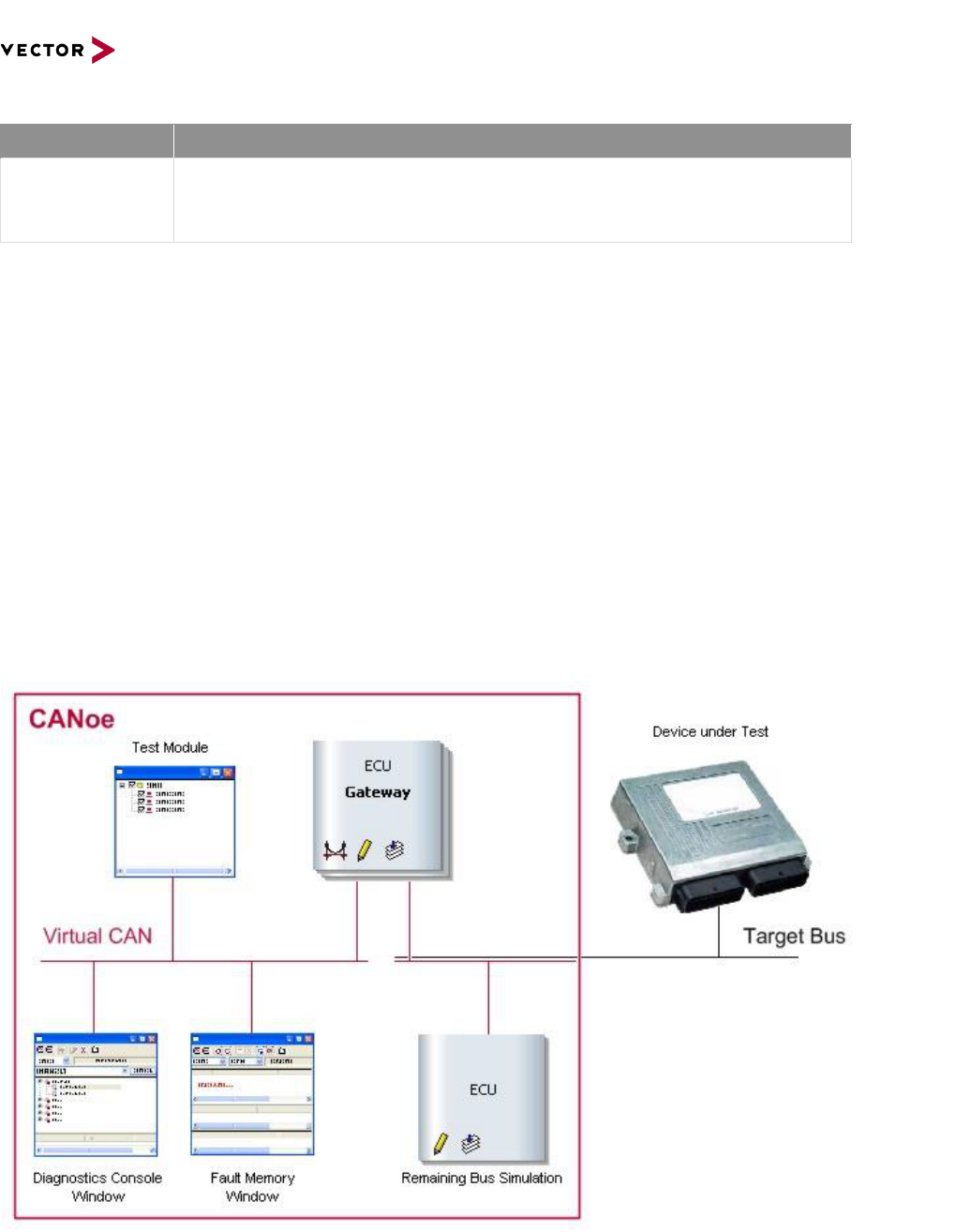
In order to make all of CANoe’s diagnostics features available to the development of ECUs connected
to any target bus system or transport protocol, a diagnostics gateway can be used:
> The diagnostic description is configured for a CAN bus, which may be “virtual”, i.e. does not
require any additional hardware.
> The ECU is connected to a remaining bus simulation as needed for the target bus’ technology,
e.g. a “master” node may be necessary.
> The diagnostics gateway is assigned to both buses. It receives requests on the CAN bus
context and forwards them to the target bus context. Responses from the ECU travel the
reverse way.
> The interpretation of the transferred data is available on the CAN bus, while the low level data
transfers are available on the target bus.
> The Diagnostic Console window and the fault memory window operate normally.
> Diagnostics test modules also work as if the ECU was connected to the CAN bus.
Figure 1: Gateway routing diagnostic information between a bus system which supports diagnostic access natively (e.g. CAN)
and the target bus system.

Diagnostics via CANoe Gateways
Copyright © 2022 - Vector Informatik GmbH 5
Contact Information: www.vector.com or +49-711-80 670-0
4.2 Gateway level
A diagnostics gateway can operate on different levels which affect the transfer delays and possibilities
to filter requests and responses.
Note
The samples only sketch one of several possible implementations!
Please refer to the CANoe help and manual for details on functions and CAPL keywords.
4.2.1 Network layer, identical transport protocols on both buses
For every CAN frame received by the gateway, a target bus frame is sent. For every target bus frame
containing an ISO transport protocol PDU the gateway receives, it sends a frame on CAN. Note that
there may be some frame modification taking place in the gateway, e.g. the ids may be changed or the
length of the frame by adding or stripping padding bytes.
Example: ISO TP level
Source Bus
CAN
ID
DLC
Data
Dir
Target
Bus ID
DLC
Data
Request:
Single
Frame
200
8
02 1A 81 00 00 00 00 00
Rx
Tx
150
24
02 1A 81 00 …
Response:
First Frame
Rx
151
24
10 09 5A 81 12 34 56 78 …
400
8
10 09 5A 81 12 34 56 78
Tx
Flow
Control
200
8
30 00 14 00 00 00 00 00
Rx
Tx
150
24
30 00 14 00 …
Consecutive
Frame
Rx
151
24
21 9A BC DE 00 00 00 00 …
400
8
21 9A BC DE 00 00 00 00
Tx
Discussion:
> No transport protocol implementations have to be present in the gateway.
> Since the data is not stored, gateways of this type provide the smallest transmission delay.
> The transport protocols used on the buses must be identical to the largest extend. Especially
the size and layout of the transferred protocol data must be the same, though additional
padding may be used (as indicated in the example).
Sample Implementation:
On message 0x200
{
<target>message 0x150 tgtMsg = { dlc = 24 };
long i;
for( i = 0; i < this.dlc; ++i)
tgtMsg.byte( i) = this.byte( i);

Diagnostics via CANoe Gateways
Copyright © 2022 - Vector Informatik GmbH 6
Contact Information: www.vector.com or +49-711-80 670-0
SetBusContext( targetBus);
output( tgtMsg);
}
On <target>message 0x150
{
message 0x400 canMsg = { dlc = 8 };
long i;
for( i = 0; i < 8; ++i)
canMsg.byte( i) = this.byte( i);
SetBusContext( canBus);
output( canMsg);
}
4.2.2 Transport layer
The gateway waits for the complete reception of a transport protocol data packet from either direction,
and forwards the data as a whole to the other bus. For a more elaborate example, see the CAN-LIN
gateway implementation in KWPSim on LIN.
Example: ISO TP with fixed length frames to ISO TP with variable length frames
Source Bus
CAN
ID
DLC
Data
Dir
Target
Bus ID
DLC
Data
Request from Tester to Gateway
200
8
02 1A 81 00 00 00 00 00
Rx
Forward of request from Gateway to ECU
Tx
160
3
02 1A 81
Response from ECU to Gateway
Rx
170
8
10 09 5A 81 12 34 56 78
Tx
160
3
30 00 14
Rx
170
4
21 9A BC DE
Forward of request from Gateway to Tester
400
8
10 09 5A 81 12 34 56 78
Tx
200
8
30 00 14 00 00 00 00 00
Rx
400
8
21 9A BC DE 00 00 00 00
Tx
Discussion:
> This type of gateway provides the most generic form of forwarding while sticking to KWP/UDS,
since it is possible to connect between any type of bus system and transport protocol.
> Note that the buffering of the transported data in the gateway will introduce a significant delay
into the communication. It might be possible to change certain protocol parameters (e.g. the
separation time in ISO TP) to reduce this delay.
> For both sides of the gateway complete implementations of the transport protocols have to be
present, and the protocols have to be configured correctly. But other than that, no in-depth
knowledge of the protocol has to be used.

Diagnostics via CANoe Gateways
Copyright © 2022 - Vector Informatik GmbH 7
Contact Information: www.vector.com or +49-711-80 670-0
Sample Implementation:
CanTp_ReceptionInd( long connHandle, byte rxBuffer[])
{
SetBusContext( targetBus);
TargetBusSend( rxBuffer, elcount( rxBuffer));
}
TargetBus_DataInd( BYTE data[])
{
SetBusContext( canBus);
CanTpSendData( connHandle, data, elcount( data))
}
4.2.3 Diagnostics layer
A gateway operating on this highest level of abstraction can translate from a completely different
communication protocol to the standard KWP/UDS, i.e. especially ECUs using proprietary protocols
for diagnostics can be made accessible to the CANoe diagnostics features.
Example: ISO TP/KWP to a proprietary protocol
Source Bus
CAN
ID
DLC
Data
Dir
Proprietary protocol
1
Request "Read all identified DTCs":
Single
Frame
200
8
04 18 02 FF 00 00 00 00
Rx
Query individual DTCs
Tx
01 01 90 01
Rx
02 01 00
Tx
01 01 90 02
Rx
02 01 13
…
Tx
01 01 90 27
Rx
02 01 15
Response carrying the identified DTCs:
First Frame
400
8
10 11 58 05 90 02 13 90
Tx
Flow
Control
200
8
30 00 14 00 00 00 00 00
Rx
Consecutive
Frames
400
8
21 08 13 90 20 15 90 21
Tx
400
8
22 15 90 27 15 00 00 00
Tx
1
Non-existing example

Diagnostics via CANoe Gateways
Copyright © 2022 - Vector Informatik GmbH 8
Contact Information: www.vector.com or +49-711-80 670-0
Discussion:
> This is the most flexible form of diagnostics gateway, since it can react to the requests on
application level.
> A gateway of this type will be very specific typically, i.e. for every ECU (type) another gateway
implementation might be necessary.
> Automatic configuration of such a gateway will be very hard to realize.
Sample Implementation:
On DiagRequest Door.FaultMemory_ReadAllIdentified
{
ClearCurrentDTCList();
gNextDTCToRead = 0x9001;
ReadNextDTC();
}
ReadNextDTC()
{
<target> message 01 mQueryOneDTC = { dlc = 4, byte(0) = 1, byte(1) = 1 };
mQueryOneDTC.byte(2) = gNextDTCToRead / 256;
mQueryOneDTC.byte(3) = (BYTE) gNextDTCToRead;
SetBusContext( targetBus);
output( mQueryOneDTC);
// There should be timeout handling; omitted here
}
On <target> message 02
{
if( this.byte(2) != 0)
AddDTCtoCurrentDTCList( gNextDTCToRead, this.byte(2));
++gNextDTCToRead;
if( gNextDTCToRead > 0x9027)
{
// Last DTC queried, so send DiagResponse to tester
SendCurrentDTCListToTester();
} else
{
ReadNextDTC();
}
}
4.3 Important notes
There are caveats that must be considered before relying on a diagnostics gateway for critical
projects:
> Depending on the gateway’s implementation, some additional delay time will be introduced
into the communication.
> With connection oriented transport protocols like DoIP or MOST High Protocol, the gateway
has to setup connections to the ECU. This may be done on demand for each diagnostic
transfer individually or once during an initialization phase. In the latter case the gateway may
have to keep this connection alive during phases where no diagnostic transfers are made.
> If a virtual CAN channel is used, hardware synchronization is only possible with CANoe
versions 7.1 and newer and driver versions 6.8 and newer.
Diagnostics via CANoe Gateways
Copyright © 2022 - Vector Informatik GmbH 9
Contact Information: www.vector.com or +49-711-80 670-0
5.0 Example: Multi-connection TP-level CAN-FlexRay gateway
5.1 Overview
In this example a complete ISO TP on CAN – AUTOSAR TP on FlexRay gateway is documented that
allows a diagnostic tester on a CAN network to simultaneously access several ECUs on a FlexRay
network.
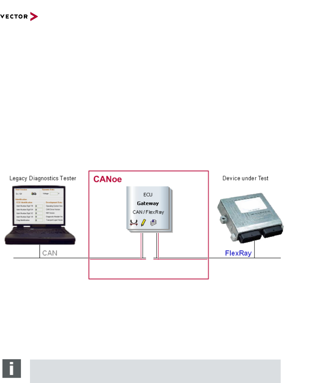
5.2 Setup
The gateway consists of one CANoe simulation node that is attached to a CAN and a FlexRay
network. The node is configured to load the modeling libraries “AutosarFlexRayTP3.vmodule” and
“OSEK_TP.vmodule” as component on all networks.
The networks have to be configured to allow communication with real hardware on CAN (if a stand-
alone tester should be used) and FlexRay: On CAN, the correct baud rate has to be selected. On
FlexRay, the cluster definitions have to be read from a FIBEX database that includes the cycle layout.
Please refer to the CANoe manual for more details.
Figure 2: Schematics of a CAN/FlexRay gateway for routing diagnostic frames.
5.3 Basic idea
The basic idea for this multi-connection CAN-FlexRay TP-level gateway is a list of pairs of connection
identifiers, pairing one connection on CAN with one on FlexRay. Whenever data arrives on a
connection, the corresponding connection on the other bus is searched, and the data received in the
gateway is sent on this connection.
Note
Please note the changed timing behavior of such a TP-level gateway (cf. 4.2.2)!

Diagnostics via CANoe Gateways
Copyright © 2022 - Vector Informatik GmbH 10
Contact Information: www.vector.com or +49-711-80 670-0
5.4 CAPL code
5.4.1 Variable declaration and initalization
In the section of global variables, the basic configuration information is kept.
variables
{
dword gContextCAN;
dword gContextFR;
// This map is used to find the corresponding connection
// This will be initialized with 0 on start, i.e. invalid
long gConnectionMap[10][2]; // [0] for CAN, [1] for FlexRay
}
During the pre-start phase, the gateway’s bus contexts have to be retrieved in order to access the
correct network later.
Note
If a modeling library like e.g. OSEK_TP.vmodule or DoIP.vmodule is added manually to a
simulation node which is connected to several networks (like in a typical gateway node),
this will create a separate instance of this modeling library for each of these networks.
This is true even if the library might not fit to the network type (e.g., if the DoIP.vmodule
was added to a CAN network). In this case, when initializing the modeling library (e.g.,
creating a connection with CanTpCreateConnection()) or when trying to send data (e.g.,
using CanTPSendData()), it is necessary to select the correct instance of the modeling
library via its “bus context”, i.e. the network to which this instance is connected. You can
select this bus context using the CAPL function setBusContext().
The network names have to be replaced with those used in the actual configuration!
on preStart
{
gContextCAN = GetBusNameContext( "CAN"); // Replace with actual
gContextFR = GetBusNameContext( "FlexRay"); // names!
On FlexRay, it might be necessary to register slots for sending during the pre-start phase. This
depends on the way FlexRay slots are defined; please refer to the respective manuals.
// Register frames used on FlexRay for TP
SetBusContext( gContextFR);
FrTP_ReserveSendSlots(120 , 1); // Replace with actual values!
}
5.4.2 Configuration of TP-connections
The TP connections are created on their respective buses and configured explicitly.
Note: The CanTp CAPL API of the OSEK_TP.vmodule modeling library is used here (available with
CANoe 7.0); please refer to its technical reference in the help (search for “OSEK TP » Functions »
Function Overview”).
on start
{
long conn; // handle for the connections
// First pair
SetBusContext( gContextCAN); // access the CAN network side
conn = CanTpCreateConnection(0); // normal mode
CanTpSetRxIdentifier( conn, 0x200); // replace with tester’s CAN ID

Diagnostics via CANoe Gateways
Copyright © 2022 - Vector Informatik GmbH 11
Contact Information: www.vector.com or +49-711-80 670-0
CanTpSetTxIdentifier( conn, 0x400); // replace with ECU’s CAN ID
CanTpSetBlockSize( conn, 0); // additional configuration
CanTpSetSTmin( conn, 5);
gConnectionMap[0][0] = conn; // Set CAN side connection handle
SetBusContext( gContextFR); // access FlexRay network side
conn = FrTP_CreateConnUnicast(120,121); // replace with ECU’s send/receive slots
FrTP_SetAddresses( conn, 2, 4444,1234); // replace with ECU’s send/receive addr.
// Routing here:
// CAN 0x200 >> FlexRay 4444
// FlexRay 1234 >> CAN 0x400
// Note that the API of this function
// depends on the used TP protocol on
// FlexRay!
FrTP_SetMaxPDULength( conn, 32); // additional configuration
gConnectionMap[0][1] = conn; // Set FlexRay side connection handle
// Second pair ...
}
5.4.3 Find corresponding connection
The following utility functions will retrieve the corresponding connection on the other bus, or return 0 if
no such connection is found.
// Return CAN connection handle for a FlexRay connection handle
long GetCanConn( long frConn)
{
dword i;
for( i = 0; i < elcount(gConnectionMap); ++i)
{
if( gConnectionMap[i][1] == frConn)
return gConnectionMap[i][0];
}
return 0;
}
// Return FlexRay connection handle for a CAN connection handle
long GetFrConn( long canConn)
{
dword i;
for( i = 0; i < elcount(gConnectionMap); ++i)
{
if( gConnectionMap[i][0] == canConn)
return gConnectionMap[i][1];
}
return 0;
}
5.4.4 CAN-side callback implementation
The TP implementation in the OSEK_TP.vmodule modeling library will indicate the arrival of data, the
completion of a data transfer, and errors by calling special CAPL callback functions. These functions
have to be implemented in the gateway.
Note that data received on a CAN connection is sent immediately on the corresponding connection on
the FlexRay network.
CanTp_ReceptionInd( long handle, BYTE data[])
{
long frConn, status;
// Find the corresponding FlexRay connection
frConn = GetFrConn( handle);

Diagnostics via CANoe Gateways
Copyright © 2022 - Vector Informatik GmbH 12
Contact Information: www.vector.com or +49-711-80 670-0
if( !frConn)
{
return; // no corresponding FlexRay connection found!
}
// Forward data to other bus
SetBusContext( gContextFR); // access FlexRay network side
status = FrTP_DataRequest( frConn, data, elcount(data));
SetBusContext( gContextCAN); // reset to CAN network side
if( status != 0)
FrTP_ErrorInd( frConn, status); // forward error to our handler
}
CanTp_SendCon( long handle, dword txCount)
{
// Sending of data succeeded
}
CanTp_ErrorInd( long handle, long error)
{
char cErrorText[13][30] = {
"(no error)"
, "Timeout while waiting for CF" // 1
, "Timeout while waiting for FC" // 2
, "Wrong Sequence Number" // 3
, "TP_DLL busy" // 4
, "Unexpected PDU" // 5
, "Timeout waiting for Tx-Ack" // 6
, "WFT Overrun" // 7
, "Buffer overflow" // 8
, "Wrong parameter" // 9
, "Invalid FlowStatus received" // 10
, "Transfer abort requested" // 11
// Sentinel
, "unknown error!"
};
long i;
if( error < 0 || error >= elcount(cErrorText))
i = elcount(cErrorText) - 1;
else
i = error;
write( "CanTp_ErrorInd(%d): %s", error, cErrorText[i]);
}
5.4.5 FlexRay-side callback implementation
The TP implementation in the AutosarFlexRayTP3.vmodule modeling library will indicate the arrival of
data, the completion of a data transfer, and errors by calling special CAPL callback functions. These
functions have to be implemented in the gateway.
Note that data received on a FlexRay connection is sent immediately on the corresponding connection
on the CAN network.
FrTP_ReceptionInd(long handle, BYTE data[])
{
long canConn, status;
// Find the corresponding CAN connection
canConn = GetCanConn( handle);
if( !canConn)
{
return; // No corresponding CAN connection found!

Diagnostics via CANoe Gateways
Copyright © 2022 - Vector Informatik GmbH 13
Contact Information: www.vector.com or +49-711-80 670-0
}
// Forward data to other bus
SetBusContext( gContextCAN); // access CAN network side
status = CanTpSendData( canConn, data, elcount(data));
SetBusContext( gContextFR); // reset to FlexRay network side
if( status != 0)
CanTp_ErrorInd( canConn, status); // forward error to our handler
}
FrTP_TxConfirmationInd( long handle)
{
// Sending of data succeeded!
}
FrTP_ErrorInd(long connectionHdl, dword error)
{
char cErrorText[14][60] = {
"(no error)"
, "Some mandatory settings are missing, e.g. the addresses"
, "The value given contradicts another setting made earlier"
, "The send request was rejected due to another transmission"
, "A reception was active when FF or SF was received"
, "A negative ACK was received for acknowledged connections"
, "The bus did not confirm transmission of a frame in time"
, "The transmitter did not receive a FC (or AF) in time"
, "The receiver did not receive the next CF in time"
, "(unknown)"
, "(unknown)"
, "The peer rejected the data since it is too long"
, "Peer sent an undefined Ack"
// Sentinel
, "unknown error!"
};
long i;
if( error < 0 || error >= elcount(cErrorText))
i = elcount(cErrorText) - 1;
else
i = error;
write( "FrTP_ErrorInd(%d): %s", error, cErrorText[i]);
}
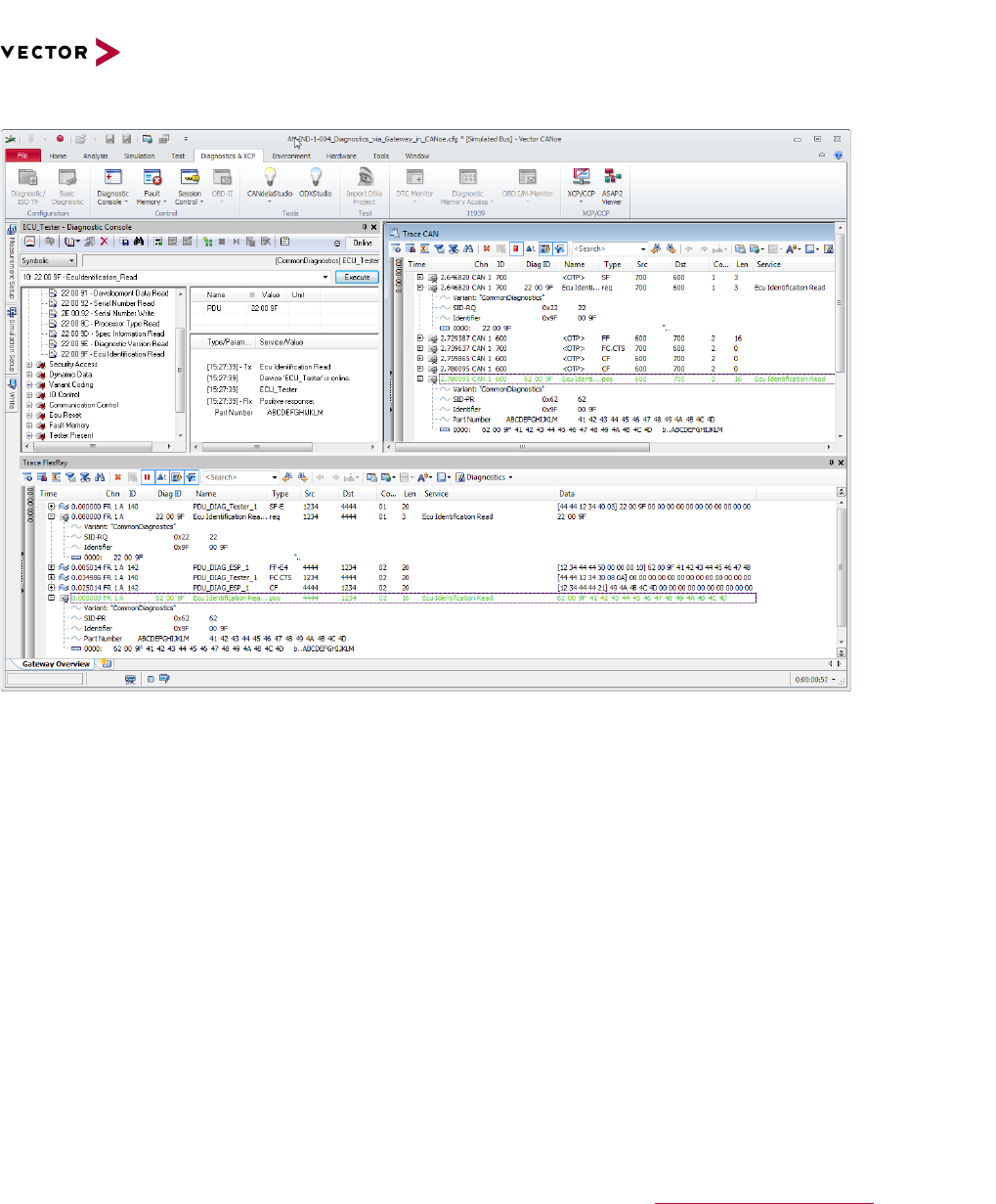
5.5 Sample data transfers
In this example a diagnostics request is sent using the Diagnostic Console on CAN to the gateway,
forwarded on FlexRay, and responded by a simulated ECU. The response is sent back via the
gateway to the Diagnostic Console. The console can display the response as if the ECU was attached
to CAN.
Diagnostics via CANoe Gateways
Copyright © 2022 - Vector Informatik GmbH 14
Contact Information: www.vector.com or +49-711-80 670-0
Figure 3: With the gateway in place, the diagnostic features of CANoe (e.g. Diagnostic Console) can be used to access the
target ECU.
6.0 Additional Resources
VECTOR APPLICATION NOTE
AN-IND-1-001 “CANoe and CANalyzer as Diagnostic Tools”
SAMPLE CONFIGURATIONS
KWPSim on LIN Demo, file location: <CANoe.LIN>\Demo_LIN_CN\KWPSim_Lin
MOST Diagnostic Gateway Demo, file location:
<CANoe.MOST>\Demo_MOST_CN\MOSTDiagnostics
CANOE/DENOE DOCUMENTATION
FlexRay TP AUTOSAR documentation in the CANoe help
7.0 Contacts
For a full list with all Vector locations and addresses worldwide, please visit http://vector.com/contact/.
