
Recommendation No 8 | Brake testing in Periodic Technical Inspection
page 0/40
Recommendation N° 8
“BRAKE TESTING IN
PERIODIC TECHNICAL
INSPECTION”
June, 19 - 2018
Document Status : Recommendation
Reference : CITA/ WG1-09-2017-110
Date of adoption : 2018-04-30
Original : English
Pages : 43 pages
Copyright © 2018 by CITA aisbl
All rights reserved. No part of this publication shall be reproduced, stored in a retrieval system, or transmitted by any means,
electronic, mechanical, photocopying, recording, or otherwise, without written permission from the publisher.
Although every precaution has been taken in the preparation of this book, the publisher and author assume no responsibility
for errors or omissions. Neither is any liability assumed for damages resulting from the use of the information contained herein.

Recommendation No 8 | Brake testing in Periodic Technical Inspection
page 1/40
CONTENT
1. INTRODUCTION ........................................................................................................................ 3
2. UNITS – ABBREVIATIONS .......................................................................................................... 4
3. SCOPE OF INSPECTION ........................................................................................................... 4
4. INSTALLATION TESTS, CONDITION TESTS ................................................................................ 5
4.1. General requirements ............................................................................................................ 5
4.2. Inspection of installation and condition .............................................................................. 5
4.3. Air Brakes .................................................................................................................................. 5
4.3.1. Slack Adjusters ................................................................................................................. 5
4.3.2. Mechanically operated LSVs ......................................................................................... 6
4.4. Hydraulic brakes ..................................................................................................................... 6
4.4.1. Tightness ............................................................................................................................ 6
4.4.2. Brake fluid test .................................................................................................................. 6
4.5. Electronically controlled systems .......................................................................................... 7
4.5.1. Anti-Lock Brake ................................................................................................................ 7
4.5.2. Electronic Stability Control ............................................................................................. 7
4.5.3. Electronic Brake System .................................................................................................. 8
4.6. Inertia/Overrun Brakes ........................................................................................................... 9
5. FUNCTION TESTS ..................................................................................................................... 10
5.1. Service Brake ......................................................................................................................... 10
5.1.1. General Requirements.................................................................................................. 10
5.1.2. Air Brakes ........................................................................................................................ 10
5.1.2.1. Method of Test for Load Sensing Valves (LSV) ....................................................... 10
5.1.2.1.1. Pneumatically operated LSVs .................................................................................. 10
5.1.2.1.2. Mechanically operated LSVs ................................................................................... 11
5.1.3. Hydraulic Brakes ............................................................................................................ 12
5.1.4. Combined Air/Hydraulic Brakes .................................................................................. 12
5.1.5. Inertia/Overrun Brakes .................................................................................................. 12
5.1.6. Recuperation ................................................................................................................. 13
5.1.7. Other Brake Systems...................................................................................................... 13
5.2. Parking Brake ......................................................................................................................... 13
5.2.1. Mechanic Parking Brake .............................................................................................. 13
5.2.2. Electric Parking Brake ................................................................................................... 13
5.3. Retarders ................................................................................................................................ 13

Recommendation No 8 | Brake testing in Periodic Technical Inspection
page 2/40
5.4. Electronically controlled systems ........................................................................................ 14
6. EFFICIENCY TESTS ................................................................................................................... 14
6.1. Scope of Measurement ....................................................................................................... 14
6.2. Measurement conditions ..................................................................................................... 14
6.2.1. Measurement on Roller Brake Tester .......................................................................... 14
6.2.1.1. Laden measurement method ................................................................................. 15
6.2.1.2. Unladen measurement method .............................................................................. 15
6.2.1.2.1. One point calculation ............................................................................................... 22
6.2.1.2.2. Two-point measurement method ........................................................................... 23
6.2.1.2.3. Multi-point measurement method .......................................................................... 23
6.2.1.2.4. Reference brake forces ............................................................................................ 24
6.2.1.2.5. RD-method ................................................................................................................. 24
6.2.2. Measurement in Road Test .......................................................................................... 24
6.2.3. Measurement on plate brake tester .......................................................................... 26
6.2.3.1. Laden measurement method ................................................................................. 26
6.2.3.2. Reference brake forces ............................................................................................ 26
6.3. Assessment of Brake Efficiency ........................................................................................... 26
6.3.1. Efficiency ........................................................................................................................ 26
6.3.1.1. Air Brakes ..................................................................................................................... 26
6.3.1.2. Hydraulic brakes ........................................................................................................ 28
6.3.1.3. Inertia / Overrun Brakes ............................................................................................ 28
6.3.2. Distribution of Brake force left-right per axle ............................................................. 29
6.3.3. Distribution of Brake Force between the Axles ......................................................... 29
6.3.4. Uniformity Fluctuation of Brake Forces ....................................................................... 29
7. EQUIPMENT............................................................................................................................. 30
7.1. Roller Brake Tester ................................................................................................................. 30
7.2. Plate Brake Tester .................................................................................................................. 32
7.3. Deceleration Recording Device ........................................................................................ 35
7.3.1. Use case ......................................................................................................................... 35
7.3.2. Main requirements ........................................................................................................ 35
7.4. Manometers .......................................................................................................................... 36
7.5. PTI Scan Tools ......................................................................................................................... 36
8. INFORMATION / DATA .......................................................................................................... 36
ANNEX 1 ............................................................................................................................................ 38
ANNEX 2 ............................................................................................................................................ 39

Recommendation No 8 | Brake testing in Periodic Technical Inspection
page 3/40
1. INTRODUCTION
CITA Recommendation No 1 lists the items that should be inspected during periodic technical
inspection (PTI), the methods of inspection and the principle reasons for failure. Section 1 covers
braking systems.
The purpose of this CITA Recommendation No 8 is to specify in more detail recommended test
methods and equipment for assessing the required safety of vehicle braking systems.
A general assumption of PTI is that new vehicles comply with legal requirements. The principal aim
of PTI is to test whether a vehicle has been properly maintained and is still roadworthy.
This CITA Recommendation is based on the requirements regarding braking systems in European
Union directive n° 2014/45/EU
1
on periodic roadworthiness tests for motor vehicles and their trailers.
It has been developed by CITA Working Group 1 and takes account of the ISO standard
2
for roller
brake testers, the 07 supplement to UNECE Regulation 13.09 concerning reference brake forces for
periodic technical inspections, and the outcome of the CITA ECSS Project.
New safety technology by use of electronic controlled systems contribute on a high level to the
avoidance of accidents as well as on the avoidance of road fatalities and a reduction of the
severity of injuries. The higher the penetration rate of such electronic safety components in vehicles
is, the more the users rely on them. Different studies (AUTOFORE; IDELSY; ECSS.) have shown that the
defect rate of electronic safety components is like pure mechanical systems. Even if the electronic
part of these systems can be controlled by OBD systems, the interface to the pure mechanical
system is subject to the usual deterioration. A test of the functionality and performance of these
electronic safety systems is necessary and possible. Where appropriate, tests of electronic systems
at braking systems are described in this recommendation.
Note that some tests are not mandatory within the European Roadworthiness Package but are best
practice of CITA members who conduct these tests.
1
Directive 2014/45/EU of the European Parliament and of the Council of 3 April 2014 on periodic roadworthiness tests for motor
vehicles and their trailers and repealing Directive 2009/40/EC (OJ L 127, 29.4.2014, p. 51)
2
ISO 21069 -1

Recommendation No 8 | Brake testing in Periodic Technical Inspection
page 4/40
2. UNITS – ABBREVIATIONS
UNITS TO RECOMMEND FOR USE ON BRAKE TESTING EQUIPMENT
Measurement
Basic units
Prefix of basic units
Alternative units
Brake force, vertical force
N
daN, kN
kgf, lbF
Air/hydraulic pressure
bar
kPa, MPa
psi
Weight
kg
t
lb
Pedal force
N
daN, kN
kgf, lbF
Note: alternative units can be used when required by national regulations.
ABBREVIATIONS:
ABS
Anti-Lock Brake System
DTC
Diagnostic Trouble Code
EBS
Electronic Brake System
ECSS
EPB
Electronically Controlled Safety Systems
Electronic Parking Brake
ESC
GUM
Electronic Stability Control System
Guide to the Expression of Uncertainty in Measurement
GVM
Gross Vehicle Mass
LSV
Load Sensing Valve
MAM
Maximum Authorised Mass
MI
Malfunction Indicator
MFDD
Mean Fully Developed Deceleration
OBD
On Board Diagnostics
PBT
Plate Brake Tester
PTI
Periodic Technical Inspection
RBT
Roller Brake Tester
RD-method
Belgian calculation method to evaluate brake efficiency for heavy duty
vehicles with air brakes
RMS
Root Mean Square
RSI
Road Side inspection
UNECE
United Nations Economic Commission for Europe
3. SCOPE OF INSPECTION
To ensure road safety, braking systems, like other safety relevant vehicle systems, shall be
tested for:
correct installation,
condition of its parts,
functioning of pedals, switches, levers, and
efficiency (performance) of the complete braking system
The tests should be possible without dismantling the parts.

Recommendation No 8 | Brake testing in Periodic Technical Inspection
page 5/40
4. INSTALLATION TESTS, CONDITION TESTS
4.1. General requirements
The installation is examined visually and/or manually and/or electronically. During this
examination the parts and components are tested for:
presence,
correct configuration,
correct mounting, quantity,
correct wiring, and
correct identification marks, if available.
Note:
To keep the safety level of the vehicles, it is recommended that the safety systems installed
"End-of-Line" remain in the vehicle during its life time and the presence is tested in the PTI.
The condition is examined visually and/or manually and/or electronically. During this
examination the parts and components are tested for:
damage, corrosion and obsolescence,
wear and slackness,
fixing, locking, assembly and installation,
free and easy movement.
Safety level “End-Of-Line” must remain.
Note:
It is recommended to check vehicles with pneumatic brakes by use of their pressure
measuring points. If these test connections are mandatory, their presence and functionality
shall be tested. Test connections that are not available can often be easily retrofitted
(approval may be necessary according to national legislation). For the equipment with test
connections, compliance with the regulations of UNECE R13 is strongly recommended.
4.2. Inspection of installation and condition
The mechanical components of the brakes which can be seen without dismantling are
examined visually and/or manually and/or electronically (see 4.1).
For condition tests, these points should be covered:
Badly chafed rods or levers.
Frayed or seized cables.
Badly damaged, corroded, seized or incorrectly fitted rods, levers or linkages.
Wear in rod or cable ends. Wear in eyes of relay levers.
Wear in clevis pins, bolts, stationary pins, pivots.
Absence of locking devices on clevis pins.
Excessively worn, contaminated, incorrectly adjusted brake linings or pads.
Fractured, damaged, insecure, misaligned brake drums or discs.
Any obstruction to free movement in the system.
Any abnormal movement of levers, rods or cables indicating maladjustment.
Security of brake back plates or discs (including transmission brakes).
Examine if there has been any obviously unsafe repair or modification carried out to
any of the mechanical components of the brake system.
4.3. Air Brakes
4.3.1. Slack Adjusters
It is not recommended that the function of automatic slack adjusters be tested directly
during the PTI.

Recommendation No 8 | Brake testing in Periodic Technical Inspection
page 6/40
Instead, they should be checked visually for correct installation (correct angles) and
adjustment (amount of slack). In addition, checks should be made for damage, excessive
wear or signs of seizure or other defects and that other related components are not missing,
disconnected or insecure.
If the checks reveal any defect that would affect the correct functioning of an automatic
slack adjuster, the vehicle should be failed.
(For an example: see annex 1)
4.3.2. Mechanically operated LSVs
Check that:
All connections, constructed to move freely, are be able to do so; and the connection
cable makes an angle of approximately 90 with a line between the connecting point for
cable and lever, and the turning point for the lever (with the lever placed in the mid
position, between empty and loaded).
Note:
The LSV may work statically, that is, a change in the lever position during braking does not
affect the output pressure of the LSV.
4.4. Hydraulic brakes
4.4.1. Tightness
Check that the hydraulic part of the brake system is tight by firmly depressing the brake. The
system/the brake master cylinder shall hold the pressure in both the partial load and the full
load positions. The vacuum brake booster under the brake master cylinder support shall be
free of brake fluid oil.
The vacuum lines of brake boosters shall be checked for leak-tightness by means of a visual
and audible inspection.
4.4.2. Brake fluid test
In case of hydraulic and air over hydraulic brake systems, it is recommended to check the
brake fluid reservoir, brake fluid warning lamp and brake fluid level and cleanness. If an
appropriate device is available, then also the boiling point of the brake fluid may be
checked.
1. Avoid damage and cross contamination.
2. Check the integrity of the brake fluid reservoir. The reservoir cap should be present.
3. Check the level of the brake fluid in the brake fluid reservoir. The brake fluid level shall
not be below the MIN mark.
4. If necessary, open the brake fluid reservoir cap and check the condition of the brake
fluid visually. Especially check for the presence of impurities, sediments or other
contaminations.
5. If necessary, check the function of the brake fluid warning light. On vehicles with the
brake fluid level sensor integrated into the reservoir cap, check whether the warning
light lights up after removing the cap.

Recommendation No 8 | Brake testing in Periodic Technical Inspection
page 7/40
4.5. Electronically controlled systems
4.5.1. Anti-Lock Brake
The following method should be regarded as the minimum standard for the PTI. It is limited
to checks which can be carried out easily and without any special vehicle make or model
specific equipment. A PTI scan tool can be used to test the installation, function, condition
or efficiency.
In case of a trailer, an appropriate testing device is necessary, when there is no truck
available with a warning signal (MI) for the trailer ABS.
(For an example: see annex 2)
Status of ABS warning signal (malfunction indicator (MI))
Check that the warning signal starts when the ignition is switched on (this is to check that
the warning signal itself is functioning). Check that the warning signal stops in the
appropriate manner. These vary from system to system. The warning signal usually stops after
a specified time lapse or when the vehicle exceeds a certain “speed threshold”. The
characteristics of all vehicle types that are likely to be tested should be known. If the
warning device stays on, the vehicle should be failed.
Electrical wiring
Check visually for faults, such as damaged wires or connectors that could affect the correct
functioning. If there is any damage that could indicate broken electrical connections, the
vehicle should be failed.
Wheel speed sensor
Check whether the wheel speed sensors are not missing or damaged.
Hydraulic / pneumatic parts
Using regular methods check hydraulic and pneumatic systems for leaks. Vehicles not
meeting normal criteria for leakage rates should be failed.
Mechanical parts
Check visually all accessible mechanical parts. If there is any mechanical defect which is
likely to affect the correct functioning of the system, the vehicle should be failed.
4.5.2. Electronic Stability Control
The following method should be regarded as the minimum standard for PTI. It is limited to
checks which can be carried out easily and without any special vehicle make or model
specific equipment. A PTI scan tool can be used to test the installation, function, condition
or efficiency.
Status of ESC warning signal (MI)
Check that the warning signal starts when the ignition is switched on (this is only a warning
signal self-test). Check that the warning signal stops in the appropriate manner. The warning
signal usually stops after a specified time lapse or when the vehicle exceeds a certain
"speed threshold". The characteristics of all the vehicle types likely to be tested should be
known. If the warning device stays on, the vehicle should be failed.

Recommendation No 8 | Brake testing in Periodic Technical Inspection
page 8/40
Electrical wiring
Check visually for faults, such as damaged wires or connectors that could affect the correct
functioning. If there is any damage that could indicate broken electrical connections, the
vehicle should be failed.
Wheel speed sensor
Check whether the wheel speed sensors are not missing or damaged.
Hydraulic / pneumatic parts
Using normal methods check hydraulic and pneumatic systems for leaks. Vehicles not
meeting normal criteria for leakage rates should be failed.
Mechanical parts
Check visually all accessible mechanical parts. If there is any mechanical defect which is
likely to affect the correct functioning of the system, the vehicle should be failed.
4.5.3. Electronic Brake System
The following method should be regarded as the minimum standard for PTI. It is limited to
checks which can be carried out easily and without any special vehicle make or model
specific equipment. A PTI scan tool can be used to test the installation, function, condition
or efficiency.
In case of a trailer, an appropriate testing device is necessary, when there is no truck
available with a warning signal (MI) for the trailer EBS.
(For an example: see annex 2)
Status of EBS warning signal (MI)
Check that the warning signal starts when the ignition is switched on (this is only a warning
signal self-test). Check that the warning signal stops in the appropriate manner. These vary
from system to system. Usually the warning signal goes out after a specified time lapse or
when the vehicle exceeds a certain "speed threshold". The characteristics of all the vehicle
types likely to be tested should be known. If the warning device stays on, the vehicle should
be failed.
Electrical wiring
Check visually for faults, such as damaged wires or connectors that could affect the correct
functioning. If there is any damage that could indicate broken electrical connections, the
vehicle should be failed.
Wheel speed sensor
Check whether the wheel speed sensors are not missing or damaged.
Hydraulic/pneumatic parts
Using normal methods check hydraulic and pneumatic systems for leaks. Vehicles not
meeting normal criteria for leakage rates should be failed.

Recommendation No 8 | Brake testing in Periodic Technical Inspection
page 9/40
Mechanical parts
Check visually all accessible mechanical parts. If there is any mechanical defect which is
likely to affect the correct functioning of the system, the vehicle should be failed.
4.6. Inertia/Overrun Brakes
Temporarily lift the trailer hitch away from the tow ball, using the jockey wheel (or Jack) to
raise the trailer.
Check that all mountings are secure.
Check all cables, rods and linkages for wear, damage and corrosion. Ensure all locking
devices are in place and secure.
Check for vertical movement in the actuator draw tube support bearings, check the end
float between the brake lever and actuator.
Check that the actuator drawtube weatherproof gaiter is in place, is secure and free from
splits, cuts or tears.
Check that the damping device is specified to be used for a trailer of MAM shown on the
Trailer Identification Plate.
Parking Brake
Check the parking brake lever pivots for security and movement.
Secondary Attachment
Identify whether a breakaway cable, or secondary coupling is required, and correct type is
fitted.
Breakaway Cable
Check cable for corrosion, damage fraying or knotting, check attachment clip operation.
Check cable guides and routing.
Check condition of ‘Burst Ring’ or alternative managed decoupling device and that it is
suitable for the trailer that it is fitted to.
Secondary Coupling
Check cable for corrosion, damage fraying or knotting, check attachment clip operation.
Check cable guides and routing.
Check that the secondary coupling is suitable for the trailer that it is fitted to.
Manual Device.
Check condition of device.

Recommendation No 8 | Brake testing in Periodic Technical Inspection
page 10/40
5. FUNCTION TESTS
5.1. Service Brake
5.1.1. General Requirements
The function is examined visually and/or manually and/or electronically. After operating
pedals, levers, switches or other operating devices which trigger an operation, this
operation must be carried out correctly in terms of time and function.
5.1.2. Air Brakes
5.1.2.1. Method of Test for Load Sensing Valves (LSV)
The LSV test is important and the correct operation of this valve has a great influence on
road safety. Due to the great time required for this test, it may not be obligatory for every
PTI.
Note:
Only applicable for vehicles with LSVs with internal simulation or LSVs fitted with an external
‘T bar’ simulation valve.
Note:
Vehicles with an electronic brake system (EBS), where the braking force control is regulated
electronically, cannot be tested as described below.
5.1.2.1.1. Pneumatically operated LSVs
As the measuring method consists of checking the actual performance against the data on
the LSV plate, an LSV plate with at least the following information must be present:
The input reference pressure.
The air suspension bellows pressure and the corresponding output pressure of the LSV
for at least 2 values, e.g. empty and the fully laden axle load.
1. Connection of manometers and pressure reducing valves
Connect manometers and pressure reducing valves as follows:
(a) Trailer or semi-trailer:
(i) Connect pressure reducing valve and manometer between the connection
of the control pressure (yellow) line of the towing vehicle and the semi-trailer.
(ii) Connect manometer in front of the input of the LSV. (Depending on the
location of the pressure measuring point, it can be placed on the output of the trailer
brake valve or on the input of the LSV.)
(b) Towing vehicle:
(i) Connect manometer in front of the input of the LSV.
(ii) Connect the pressure reducing valve and manometer between the air
pressure reservoir and the simulation input of the LSV.
(iii) Connect manometer on the output of the LSV.
2. Input reference pressure
(a) Trailer or semi-trailer:
Set the input reference pressure to the value specified on the LSV plate using pressure
reducing valve and manometer. Press the brake pedal fully down and check the

Recommendation No 8 | Brake testing in Periodic Technical Inspection
page 11/40
value of the manometer. The Manometer shows the input pressure for the LSV and the
difference between manometers and shows the predominance of the trailer brake
valve. The input pressure is adjusted using pressure reducing valve until manometer
reads the input reference pressure shown on the LSV plate.
(b) Towing vehicle:
The input reference pressure is not regulated by a pressure reducing valve; the brake
pedal should be applied until manometer indicates the reference pressure shown on
the LSV plate.
3. Suspension bellows pressure
Different suspension bellows pressures are simulated by adjusting pressure reducing valve.
4. Checking the LSV
The progressive operation of the LSV must be tested by checking three points. It is not
sufficient to check only the empty and loaded state points.
Point 1:
Pressure reducing valve is set to simulate a bellows pressure of 0.00 bar.
If one of the two suspension bellows pressures remains present at the LSV, this ‘empty
condition’ pressure will be the first point to check instead of 0.00 bar.
When the input reference pressure is set, the output pressure of the LSV when the brake is
applied must be the pressure given on the LSV plate for the empty condition, with some
tolerance (e.g. +/- 0.20 bar).
Point 2:
The brakes are released, and the pressure-reducing valve is set to simulate an increase of
0.20 bar in the bellows pressure compared to the empty state.
When the input reference pressure is reset, the output pressure of the LSV must show the
expected increase in pressure (e.g. +0.20 bar) compared to the pressure measured at
point 1 with some tolerance (e.g. +/- 0.10 bar).
Point 3:
The brakes are released, and the pressure-reducing valve is set to simulate a pressure,
which is 0.1 bar lower than the bellows pressure in loaded state. If the input reference
pressure is reset, the output pressure for the LSV must show the expected diminution in
pressure (e.g. -0.30 bar) compared to the pressure given on the LSV plate for the full laden
condition – with some tolerance (e.g. +/- 0.20 bar).
Note:
The LSVs on trailers and semi-trailers work statically; i.e. during braking, the LSV output is
not adjusted in response to a change in the control signal (bellows pressure). The brakes
must be released before each new suspension bellows pressure is simulated.
5.1.2.1.2. Mechanically operated LSVs
As the measuring method consists of checking the actual performance against the data on
the LSV plate, an LSV plate with at least the following information must be present:
The input reference pressure.
The spring movement fs in mm. (deflection of the springs in loaded state; information
from the axle constructor).
The lever length L in mm.
The axle load and the corresponding output pressure of the LSV for at least 2 values,
e.g. empty and the fully laden axle load.

Recommendation No 8 | Brake testing in Periodic Technical Inspection
page 12/40
1. Connection of manometers and pressure reducing valves
The manometers and the pressure reducing valve should be connected in the same way
as for a pneumatic LSV. However, in this case, the suspension bellows pressure cannot be
simulated.
2. Input reference pressure
The input reference pressure is set in the same way as with a pneumatically driven LSV.
3. Checking the LSV
Provided the vehicle is submitted empty, when the brakes are fully applied, manometer
5 should show the pressure given on the LSV plate for the empty condition, with some
tolerance (e.g. +/- 0.20 bar)
A check in a simulated loaded condition can only be achieved if the mechanical lever
can be adjusted manually or using external load simulation. If the control lever can be
moved to the position of maximum load, the accompanying output pressure can be
measured and compared with the corresponding value on the LSV plate. For towed
vehicles this is usually not possible, leaving only the correct lever length L to be checked
against the values given on the LSV plate.
5.1.3. Hydraulic Brakes
If fitted, check the vacuum brake booster as follows: Is the engine turned off, press the
brake pedal several times. The brake pedal must be clearly refilled, when starting the
engine.
If fitted, check the settings of the braking force controllers and braking force limiters if target
values exist (LSV plate) and if test connections are available.
If fitted, check the warning device of the pump und accumulator by fully actuating the
service brake four times while the engine is not running; the warning device shall not
respond.
Otherwise proceed as with the air braking systems (see point 5.1.2).
5.1.4. Combined Air/Hydraulic Brakes
With combined braking systems, the tests described for air braking systems and hydraulic
braking systems in Sections 5.1.2 and 5.1.3 shall be performed accordingly. In addition, the
requirements of ISO 21069-2 concerning the testing of air over hydraulic braking systems
should be applied.
5.1.5. Inertia / Overrun Brakes
If the actuating device of the parking brake is a ratchet type, check the action of the
locking pawl and its release mechanism and ensure that the ratchet does not release
unexpectedly when a load is applied to the lever.

Recommendation No 8 | Brake testing in Periodic Technical Inspection
page 13/40
Check the following points visually by a road test with watching the retardation from
outside:
The brake actuator shall apply smoothly and progressively, and the brake actuator shall
release to its original start position smoothly and progressively. If fitted, the application and
release shall be under the control of the damping device. The stroke of the drawbar must
not exceed about 2/3 of the total overrun travel; this does not apply for the testing of the
reversing system.
5.1.6. Recuperation
If a recuperation system is fitted, check the correct function of the warning device and that
the warning device displays no malfunction.
If possible, the recuperation should be tested during a test drive with the battery not fully
charged. The system must noticeably decelerate the vehicle and the charge indicator (if
fitted) displays “charging” when the recuperation is activated.
5.1.7. Other Brake Systems
Other braking systems with different designs must be inspected based on the specifications
of the braking systems referred above.
5.2. Parking Brake
Note: A parking brake can be a very vulnerable system, for example a transmission brake of
a Land Rover or the small drum brakes of Mercedes Benz, or Iveco Daily. So, it is advisable to
test the parking brake with care.
5.2.1. Mechanic Parking Brake
Mechanically actuated parking brakes shall normally be tested on the roller brake tester.
The braking power must be graduated and equal on both sides of the vehicle. The
difference between right and left shall not be more than 50%, starting from the higher value.
5.2.2. Electric Parking Brake
Electrically actuated parking brakes shall normally be tested on the roller brake tester. The
braking power must be graduated and equal on both sides of the vehicle. The difference
between right and left should not be more than 50%, starting from the higher value.
An exception can be made, where the EPB switch triggers service brakes via the ESC if
wheel speed is detected. In these cases, the maximum permissible right-left deviation may
be 95% (not inoperative on one side).
5.3. Retarders
Apart from a check that the retarder control is capable of gradual variation, it is not
recommended that the function of retarders is tested at a PTI.
The normal procedure for checking retarders at PTI is a visual check for any problems that
could affect its correct functioning and, for systems with on-board diagnostics, that no
malfunction signal is activated.

Recommendation No 8 | Brake testing in Periodic Technical Inspection
page 14/40
Check visually for mechanical damage to the retarder, for leaks in hydraulic retarders and
for damage to the electrical system in electromagnetic retarders.
If there is a malfunction signal or any damage that reduces the retarder’s ability to function
correctly the vehicle should be failed.
5.4. Electronically controlled systems
A test of these electronic safety systems is possible and would add to road safety.
In the ECSS report
(https://ec.europa.eu/transport/road_safety/sites/roadsafety/files/pdf/projects_sources/ecs
s_final_report.pdf ; chapter 5.1.1.2), recommended test methods for brake testing with
direct focus on ECSS (ABS, ESC, EBS) have been proposed.
So far, these methods have not been implemented yet.
6. EFFICIENCY TESTS
6.1. Scope of Measurement
PTI must generally be carried out in the condition vehicles are presented by their owners.
Depending on national legislation, it can be required to present vehicles in laden condition.
In most cases, heavy vehicles are presented unloaded or only partially loaded. This means that
maximum braking forces can be difficult to establish on a roller brake tester, since the wheels
tend to lock before the maximum air pressure in the service line is reached.
There are several basic approaches to overcome this problem. One is to apply an artificial load
on the vehicle or the axle.
One other is to extrapolate from air pressure and brake force values registered during roller
brake testing in condition as presented.
A third possibility is to use reference brake forces in sense of UNECE R13. With this method one
has furthermore an axle-wise test and evaluation of the service brakes.
As well as specifying the test method, the properties of the equipment that is required (air
pressure gauges and connectors) are also specified. Via a PTI scan tool an equivalent value for
the Brake pressure can be read out as reference value. So, these methods are applicable to
heavy vehicles with fully pneumatic braking systems, or mainly pneumatic braking systems
where only part of the transmission is hydraulic, and this part does not contain any reduction
valves. These methods also apply to hydraulic braked vehicles with ESC-System.
The method takes as a basic presumption that the brake forces increase in direct proportion to
the service line air pressure in the relevant range.
6.2. Measurement conditions
6.2.1. Measurement on Roller Brake Tester
There are two kinds of brake tests for testing the braking ratio which relates to the maximum
authorised mass. (Most of these methods are described for heavy duty vehicles in ISO
21069):

Recommendation No 8 | Brake testing in Periodic Technical Inspection
page 15/40
By using a laden vehicle which relates to the maximum authorised mass and a direct
measurement method e.g.
o The braking rate is calculated by the direct measurement of the axle brake
forces (laden measurement method)
o Reference braking forces methods without further calculation.
By using a vehicle which relates not to the maximum authorised mass (because of
unladen condition of the vehicle) and an indirect measure method e.g.
o Reference Brake Forces
o One-point measurement method
o Two-point measurement method
o Multi-point measurement method
o Reference brake forces used together with one of the methods above
o Alternative measurement methods e.g. the "RD method" used in Belgium, the
two-points measurement used in the Netherlands, the One-point
measurement method by using min 1.7 bar (for pneumatic brake systems)
brake actuator pressure used in Germany.
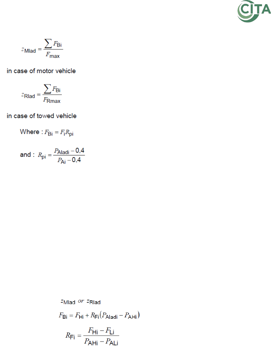
6.2.1.1. Laden measurement method
The braking rate shall be determined directly by measuring the braking forces for the
vehicle in the laden condition.
The laden braking rate calculation requires no extrapolation, being simply given by the
following formula:
in case of motor vehicle
in case of towed vehicle
To establish the braking ratio which relates to the maximum authorised mass or, in the
case of semi-trailers, to the sum of the authorised axle loads, the test mass should be at
least 2/3 of the maximum authorised mass (or sum of the authorised axle loads).
6.2.1.2. Unladen measurement method
By using a not fully laden vehicle, less brake forces and brake actuator pressures are
met as by braking with a laden vehicle.
There should always be a minimum test brake cylinder pressure as a minimum test
condition. There are different reasons to use a minimum requirement for cylinder
pressure:

Recommendation No 8 | Brake testing in Periodic Technical Inspection
page 16/40
Since for an extrapolation method the end point of the measurement should be
in the linear behaviour zone of the brake measurement. This linear zone is not
ensured beneath braking ratio of 10% of a fully laden vehicle. This means that if
the brake actuator pressure is less than 2 bars the brake curve is not yet in his
linear part.
For a correct calculation at least 30% of the design brake actuator pressure shall
be achieved by suitable loading of the axle or simulation of load (for pneumatic
brake systems). This is not necessary, if the required minimum retardation for the
vehicle is reached in extrapolation even with a reduced design brake actuator
pressure for the respective axis. In this case, the reduced design brake actuator
pressure shall be reduced to the extent that the pressure at which the wheels are
blocking is not less than 30% of the reduced brake pressure (p
red
= p
dis
/0.3).
To increase the accuracy of the extrapolation methods by heaving a measured
pressure as close as possible to the calculated pressure (guaranteed pressure).
The Netherlands uses here a minimum of 2.4 bar cylinder pressure.
Higher brake cylinder pressure should be accompanied with a higher weight on the
wheels. To obtain maximum braking force there must be enough weight on the wheels,
since the brake force on a roller brake tester is equal to the vertical force of the weight
multiplied with the friction coefficient between the roller and the tire.
There are different solutions used in national PTI schemes to increase either the friction
force (adhesion), either the brake actuator pressure, or both. A short description of
these possible tools follows:
1. Presenting the vehicle with a partial load
Customers present their vehicle with a partial load in order to obtain the minimum
requirement of the brake actuator pressure to make a valid brake test.
Principle:
The load Sensing Valve (LSV), of the vehicle reacts on the partial
load and will send a higher pressure to the axle. Higher load means
higher friction forces and thus higher brake forces.
Advantages:
No additional equipment or time needed to perform the brake test;
Disadvantages:
Presenting a vehicle in a laden condition is not always possible e.g.
gas tank trucks, milk tank trucks. Also, could it be that a laden
vehicle gives problems by the further inspection of the vehicle.
Otherwise it could be dangerous for the inspector.
Remarks:
assessment of security of cargo;
Recommendation No 8 | Brake testing in Periodic Technical Inspection
page 17/40
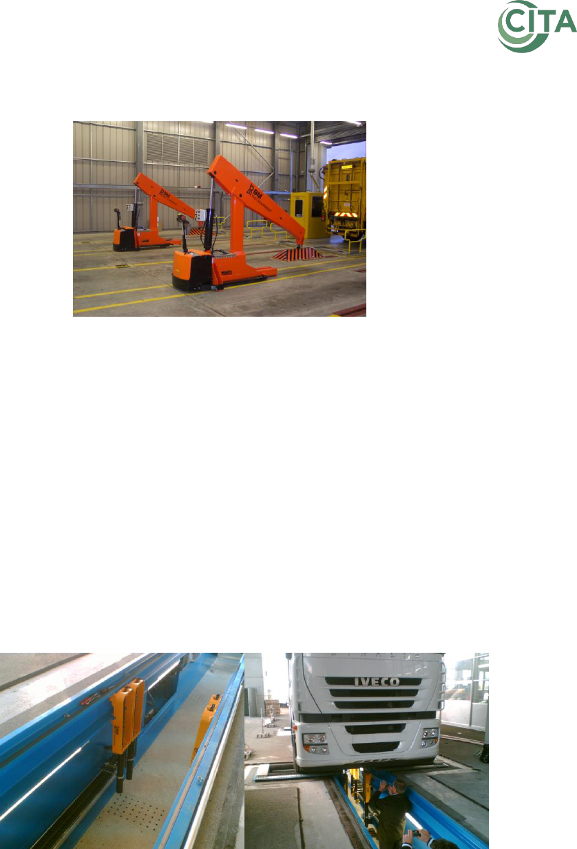
2. Chassis load simulation: applied to chassis from top-down
An operator moves the load simulator, based on an electrical pallet truck with a
crane with a load arm system mounted on it, to its position (behind or at the side of
the vehicle). The simulator is then fixed to the floor via Anchor pins, which are
quickly placed into concreted rails systems in the floor. The crane system can then
push the chassis down.
Principle:
By pushing down the chassis, the LSV will react as well as a higher
Friction Force will be generated;
Advantages:
Real load simulation – the Load Sensing Valve as well as the
suspension system of the vehicle is activated and reacts as a laden
vehicle, easy to retrofit.
Disadvantages:
Setup time and space needed, not always possible because the
inspection pit.
Remarks:
Only applicable when the vehicle has a load platform.
3. Chassis load simulation: pulling on the chassis of the vehicle
By using a pulling device, the vehicle can be pulled down. Usually there are one or
more hydraulic cylinders located in the inspection pit. Each cylinder can be hooked
up to the chassis via chains and claws. In many cases, the hydraulic cylinder is
mounted on rails and thus movable. In the examination of tandem axles, the claws
can stay on the chassis once fitted.
With a remote control to pulling down action is commanded (hydraulic cylinders).
Due to the rail system axle by axle can be tested by pulling down and releasing the
action and moving to the next axle without any action in the inspection pit.
Recommendation No 8 | Brake testing in Periodic Technical Inspection
page 18/40
Principle:
By pulling down the chassis, the LSV will react as well as a higher
Friction Force will be generated.
Advantages:
Real load simulation – the Load Sensing Valve as well as the
suspension system of the vehicle is activated and reacts as a laden
vehicle, easy to retrofit, low-priced;
By using rails, it doesn’t require to be moved or fitted for each axle
on the vehicle.
Disadvantages:
Time intensive because of setup time. There could be danger to
damage the chassis.
Remarks:
Sometimes difficult or even impossible to fix installation on the
vehicle.
Note:
To avoid structural damage on vehicle parts, it must be ensured,
that the fixing point on the vehicle is capable to bear the necessary
forces.
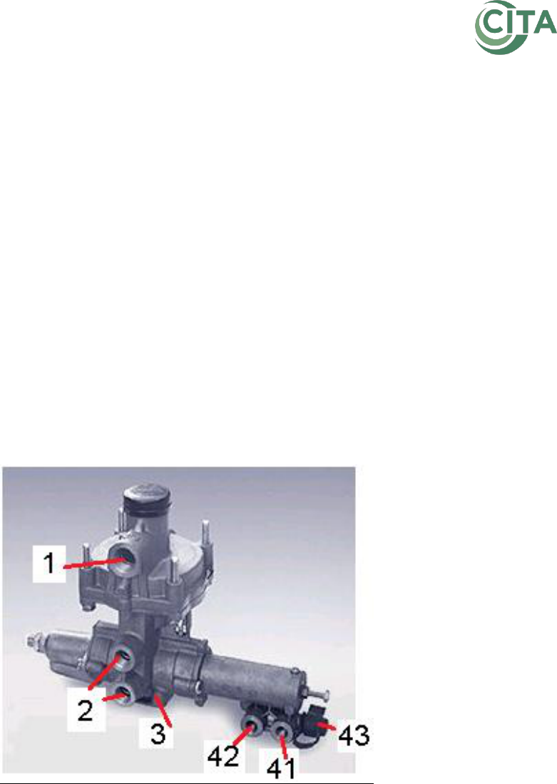
4. Raise the brake actuator pressure by opening the load sensing valve
(LSV)
Example of connections on a pneumatically operated LSV (ISO-8786)
1: supply of energy
2: energy delivery
3: exhaust port
4: control port (device inlet)
41: air suspension
42: air suspension
43: test connection (simulation)
Connect air pressure on the simulation valve of the LSV (connection P43). The P41
and P42 connections of the LVS, the normal pilot pressures of the LSV, are at that
moment cut off. The LSV will only react by the pressure from the simulation valve
P43. Send a pilot pressure that corresponds to the loaded condition of air spring via
the simulation valve P43. The LSV will react as if the vehicle was laden.

Recommendation No 8 | Brake testing in Periodic Technical Inspection
page 19/40
Principle:
By simulating the air spring pressure of the laden vehicle via the
simulation valve of the LSV, a higher brake actuator pressure can
be reached.
Advantages:
Brake system of the vehicle reacts as a loaded vehicle.
Disadvantages:
Setup time, external air pressure needed.
No gain in friction Force because of no extra load on the axle.
Remarks:
Not every LSV valve has a simulation valve included; in this case
separated simulation valve should be integrated in the brake
system of the vehicle.
There is no gain in Friction Force, so in combination with a system
where a Friction Force gain system (7, 8 or 9) is installed, the best
load simulation can be met.
5. Raise the brake actuator pressure by putting the raise/lower valve in the
blocked lowering position
Block the Raise/Lower Valve in de lowering position. In certain cases, the Load
Sensing Valve will react as if the vehicle is fully laden.
Principle:
The brake- and suspension system of the vehicle can be in certain
cases combined as following. The piloting pressure from the Load
Sensing Valve is taken on the one hand from the Air Spring pressure
and on the other hand from the Levelling Valve.
By putting the Raise/Lower Valve in the lowering position, the
Levelling Valve will try to send air to the Air Spring in order to put the
vehicle higher in the driving condition. The Air Spring will not get this
air because on his way, the air is blocked by the Raise/Lower Valve.
But by having a connection from the Levelling Valve to the piloting
pressure of the LSV, the pressure from the suspension reservoir will be
the piloting pressure of the LSV. So, the LSV and the brake system of
the vehicle will react as if the vehicle was fully laden.
Advantages:
Brake system of the vehicle reacts as a loaded vehicle;
Easy to manage;
Fast to use.
Disadvantages:
No gain in Friction Force.
Remarks:
Works only when one of the piloting pressures from the Load Sensing
Valve is taken from the Levelling Valve – it is not always clear which
vehicle has his LSV and suspension system integrated in this way;
There is no gain in Friction Force, so in combination with a system
where a Friction Force gain system (7, 8 or 9) is installed, the best
load simulation can be met.

Recommendation No 8 | Brake testing in Periodic Technical Inspection
page 20/40
6. Raise the brake actuator pressure by disconnecting the EBS
Brake with the contact switched off, or with the EBS alimentation cable
disconnected in case of a towed vehicle.
Principle:
When the EBS has no alimentation, certain EBS systems will react,
when braking, as if the LSV-function is in a fully laden condition.
Advantages:
Brake system of the vehicle reacts as a loaded vehicle.
Disadvantages:
No gain in Friction Force.
Remarks:
Reaction depends on the EBS system. Not all EBS systems have the
same behaviour.
There is no gain in Friction Force, so in combination with a system
where a Friction Force gain system (7, 8 or 9) is installed, the best
load simulation can be met.
7. Conventional axle load simulation: pulling down the axle
Chains or mounting straps are to be fitted to each axle before the brake test. The
pulling down of the axle is then done with a fix or movable hydraulic cylinder. Chains
or straps are to be removed again before moving the vehicle forward. Operation
must be repeated for each axle.
Principle:
Pulling down an axle will create a higher vertical force and thus a
higher Friction Force.
Advantages:
Easy installed or retrofitted in inspection pit.
Disadvantages:
Setup time;
The use of chains could give a danger to damage the axle or tubes
and wires that are fixes on the axle. The maximum pulling force
should not exceed 50% of the maximum axle.
Remarks:
Due to the simulated load applied to the axle, the Load Sensing
Valve as well as the suspension system of the vehicle is not
activated nor tested.
8. Axle load simulation: lifting up the tested axle
This is a load simulation by a lift-able roller set. The brake tester can be raised and
controlled via remote control. There are brake testers with horizontal lift-able roller
sets and other with inclinable roller sets who turns around a fixed point.
Principle:
Lifting a tandem- or tridem-axle the weight from this group will be
transferred to the one lifted axle.*
Advantages:
Quick setup time.

Recommendation No 8 | Brake testing in Periodic Technical Inspection
page 21/40
no connection to the vehicle is required.
Disadvantages:
price;
can only be used for tandem- or tridem-axles.
Remarks:
It is recommended not to use the system until the axle is completely
lifted from the ground in order not to damage the air spring when
he rolls back over his seat by the action lifting down;
Due to the simulated load applied to the axle, the Load Sensing
Valve as well as the suspension system of the vehicle is not
activated nor tested; The vehicle brake system will only react
towards the higher mass (higher brake actuator pressure) when on
the lifted axle the levelling valve (air suspension) or the mechanical
Load Sensing Valve LSV (mechanic suspension) is mounted, in the
other cases the gain will be only a higher Friction Force.
*Note:
If the test bench can lift and brake the wheels of an axle one after
the others, it is possible to higher the load of the actually measured
single wheel with the load from the load of the actually not
measured wheel (depending on the stiffness of the chassis).
Therefore, it is possible to achieve higher brake forces also on single
axle aggregates without the use of any pulling down equipment.
9. Alternative to the conventional axle load simulation: by fixing the chassis
or axle to the floor/pit and lifting the roller brake tester
Chains or straps are to be fitted to the chassis or axle before the brake test. The
roller set is then raised. Chains are to be removed again before moving the vehicle
forward. Operation must be repeated for each axle.
Principle:
Pulling down an axle will create a higher vertical force and thus a
higher Friction Force.
Advantages:
Flexibility by using only the lifting system, or the fixing and lifting
system.
Disadvantages:
Costly to install or retrofit.
Remarks:
In some cases, the vehicle frame instead of the axle can be fixed;
Due to the simulated load applied to the axle, the Load Sensing
Valve as well as the suspension system of the vehicle is not
activated nor tested.
Note:
To avoid structural damage on vehicle parts, it must be ensured,
that the fixing point on the vehicle is capable to bear the necessary
forces.
10. Reversed turning brake rolls
In this case, the vehicle is tested wheel by wheel while the rollers from one side turn
in opposite direction in comparison with the rollers from the other side. The brake
force from the wheel that turns forward is measured. The brake force from the other
wheel is measured in a second brake action when the both roller sets turn in the
other direction as in the first set.

Recommendation No 8 | Brake testing in Periodic Technical Inspection
page 22/40
Principle:
In a normal roller brake tester, the tested axle has the intension to
climb up against the second roller. When the axle does this, the
commutation roll, will stop the brake tester. Therefore, the second
roller is sometimes placed higher. By having reversed turning rolls
the axle will be more having the intention to stay in the rollers, and
thus a higher brake force than with a normal brake tester can be
attaint.
Advantages:
Small gain on brake actuator pressure and corresponding brake
force.
Disadvantages:
Brake test must be done wheel per wheel (double time required);
brake tester software should be adopted to this test;
The gain in a minimum but could be sufficient to get the required
brake actuator pressure.
Remarks:
Helpful by testing parking brakes, during the test of the service
brake, the vehicle is fixed on the floor, because all wheels brake.
Tools to increase the friction force (adhesion) can be used in combination with those to
increase the brake actuator pressure, or visa-versa.
Overview of the different tools used in PTI to increase either the friction force (adhesion), either the
brake actuator pressure, or both
Friction
Force
Brake
actuator
pressure
Setup time
1
Presenting the vehicle with a partial load
++
+
0
2
Chassis load simulation: Applied to chassis from top-down
++
+
++
3
Chassis load simulation: Pulling on the chassis of the vehicle
++
+
++
4
Raise the Brake Actuator Pressure by opening the LSV valve (Load
sensing valve)
0
+
++
5
Raise the Brake Actuator Pressure by putting the Raise/lower valve
in the blocked lowering position
0
+
+
6
Raise the Brake Actuator Pressure by disconnecting the EBS
0
+
+
7
Conventional Axle Load Simulation: Pulling down the axle
++
0
++
8
Axle load simulation: Lifting up the tested axle
++
0
+
9
Alternative to the Conventional Axle Load Simulation: Pulling down
the axle, by fixing the chassis or axle and lifting the roller brake tester
++
+
++
10
Reversed turning brake rolls
+
0
+
Depending on national legislation and boundary conditions, these tools may also be
combined.
6.2.1.2.1. One-point calculation
This is an extrapolation method requiring only a single braking force measurement for each
wheel/axle. The test shall be carried out with the highest achievable braking forces with the
corresponding brake actuator pressure beneath the locking limit of the wheels.
This generates the highest braking forces without too high wheel slip on the rollers.
The one-point measurement is possible since the starting point is standardized at 40 kPa and
this assumes a fixed value for all brake threshold pressures. The measured braking forces at
each axle shall then be extrapolated to the minimum design pressure p
Aladi
. The braking
rate of the vehicle is given laden by the follow formula:
Recommendation No 8 | Brake testing in Periodic Technical Inspection
page 23/40
Note: For a correct calculation the brake actuator pressure reached before blocking the
wheels shall correspond to point 6.2.1.2.
6.2.1.2.2. Two-point measurement method
The starting point is not standardized. The braking force shall be measured at a low brake
actuator pressure a little above the threshold point where braking force can be measured.
The second (main) measurement shall be performed with the highest applicable braking
forces with the corresponding brake actuator pressure beneath the locking limit of the
wheels.
Again, the measured braking forces at each axle shall be extrapolated to the minimum
design pressure.
The laden braking rate is given from:
Note: For a correct calculation the brake actuator pressure reached before blocking the
wheels shall correspond to point 6.2.1.2.
6.2.1.2.3. Multi-point measurement method
The laden braking rate may also be achieved by extrapolating multiple measurements of
braking forces and actuator pressures using least square numerical methods.

Recommendation No 8 | Brake testing in Periodic Technical Inspection
page 24/40
6.2.1.2.4. Reference brake forces
Reference Braking Forces as described in the UNECE R13 mean the braking forces of one
axle generated at the circumference of the tyre on a roller brake tester, relative to brake
actuator pressure and declared at time of type approval. These are described in detail in
points 5.1.4.6. to 5.1.4.7.1. of R13.
The measured braking forces and corresponding actuator pressures shall be compared with
the reference braking forces for evaluation purposes.
Note:
For a correct brake testing it might be appropriate to provide a minimum pressure for the
reference braking force method, in which the wheels may block at the earliest. In Germany
a pressure of 1.7 bar is required. The 1.7 bar does not have to be reached if the reference
braking force of 1.7 bar has been already reached at a braking pressure below 1.7 bar.
6.2.1.2.5. RD-method
In Belgium for each vehicle braking forces of one axle generated at the circumference of
the tyre on a roller brake tester, relative to brake actuator pressure are calculated for each
axle and the vehicle (RD-lines). The calculation considers that the linear behaviour zone of
the brake measurement is not covered beneath braking ratio of 10% of a fully laden vehicle
and that the distribution of braking among the axles of vehicles.
The measured braking forces and corresponding actuator pressures shall be compared with
the calculated RD-lines for evaluation purposes.
6.2.2. Measurement in Road Test
Usually the braking efficiency shall be measured on a roller or plate brake tester. But in the
following cases a measurement in a road test is valid:
o Vehicles for which testing on a roller or plate brake tester is not possible for reasons related
to the chassis geometry or other vehicle-specific reasons,
o Vehicles designed to have a maximum speed of ≤ 40 km/h,
o Agricultural or forestry vehicles, including any attached machinery, in accordance with
Article 2, Points j, k and I of Directive 2003/37/EC (vehicle classes T, R and S),
o Motorcycles with and without sidecars, quads and trikes depending on the type of the
braking test device.
When braking on the road, it shall be checked whether the vehicle reaches the prescribed
minimum deceleration about permissible total mass.
For the direct determination of the brake efficiency of the vehicle a deceleration recording
instrument (decelerometer) shall be used. Only in justified cases (e.g. if correct placement of
the brake-measuring device is not possible due to the design of the vehicle, e.g. with
motorcycles, or if all braked wheels are locked on a non-slip, dry road surface), then the
braking efficiency may be assessed without a recording brake-measuring device; this must
be documented in the appropriate inspection report.
For the road test following conditions must be observed:

Recommendation No 8 | Brake testing in Periodic Technical Inspection
page 25/40
(1) The test site must be sufficiently secured against the possibility that persons, vehicles,
animals etc. enter it. Objects or other obstacles which could endanger the road test must not
to be present. No persons are allowed to stay in the intermediate proximity of the vehicle or
it´s supposed trajectory during the road test. The surface of the site must be asphalt, concrete
(cement) or other material with similar qualities; the site surface must not have considerably
worsened adhesive qualities (such as icy, covered with snow etc.) during the test.
(2) It is possible to carry out the road test only after all the other inspection items that
are part of the PTI were finished and no defect that could endanger the safety of the test
was detected.
(3) During the road test, the vehicle is driven by the inspector or the vehicle´s driver
following the inspector’s instructions. In that case, the driver must be familiar with the safety of
the road test principles.
(4) In case of an air-pressure or combined brake system (air over liquid), the pressure
must be supplemented to the level that corresponds with the prescribed working pressure
(the required air pressure is in general achieved as soon as the pressure regulator releases the
excess pressure).
(5) In case of the T category vehicles with two-pedal service brake handling, the
simultaneous operation of both pedals must be secured by a latch. In case of T category
vehicles with one-pedal handling, the lever of the hydraulic distributor must be in the central
position.
The process of the road test with the use of the decelerometer:
(1) The decelerometer is placed in the vehicle or fastened according to the instructions
of use.
(2) The vehicle after setting in motion from the starting point accelerates to the initial
speed of measurement. The intensity of the speed of measurement is set according to
immediate conditions of measurement and state of the site in a way that the safety of the
trial is not endangered and that it is possible to stop the vehicle safely before the trial site
ends. It is considered that a speed higher than 20 km.h
-1
is a sufficient initial speed.
(3) Immediately before starting to brake, the inspector (vehicle driver) turns off the
clutch (in case of manual transmission vehicles) and intensively steps on the service brake
pedal. While doing that he must pay attention to the fact that the vehicle – as the
circumstances allow – braked shortly before the wheel-blocking limit. The vehicle is braked
until it stops completely.
(4) Afterwards, the mean fully developed deceleration (MFDD) or the braking ratio
gained by the service brake is identified (measured by the deceleration recording device) as
well as the possible deviation from the straight drive direction during the braking process.
(5) From the value of the MFDD, the equivalent deceleration value is calculated by the
relation
(%),
in which the meaning of the symbols is as following:
a – MFDD of the vehicle that was reached by the service brake in (m.s
-2
),
g – gravitational acceleration (≈ 9,81 m.s
-2
).
%100
g
a
Z

Recommendation No 8 | Brake testing in Periodic Technical Inspection
page 26/40
In case the decelerometer directly indicates the deceleration, value this indicated value is
used and there is no need to carry out the calculation.
(6) The value of the calculated deceleration or the value of the measured deceleration
is compared to the prescribed value for the given vehicle.
Note: Where available, the detection of brake force distribution front/rear and
left/right (e.g. by interpretation of the six degrees of freedom), and of reference
values should be used.
6.2.3. Measurement on plate brake tester
6.2.3.1. Laden measurement method
The braking rate shall be determined directly by measuring the braking forces for the
vehicle in the laden condition.
The laden braking rate calculation requires no extrapolation, being simply given by the
following formula:
in case of motor vehicle
6.2.3.2. Reference brake forces
Reference Braking Forces as described in the UNECE R13 mean the braking forces of one
axle generated at the circumference of the tire on a roller brake tester, relative to brake
actuator pressure and declared at time of type approval. These are described in detail
in points 5.1.4.6. to 5.1.4.7.1. of R13.
The measured braking forces and corresponding actuator pressures shall be compared
with the reference braking forces for evaluation purposes.
In Germany, plate brake testers measure the brake force of each wheel and calculate
the mean value of brake forces between 5 to 2 km/h.
With a PTI-Scan-Tool, it is possible to read out an equivalent value to brake pressure as
reference value.
These measured values must be also calculated to mean value between 5 to 2 km/h.
The calculated mean brake forces and the calculated mean reference value shall be
compared with the reference braking forces.
6.3. Assessment of Brake Efficiency
6.3.1. Efficiency
6.3.1.1. Air Brakes
METHOD FOR THE PTI OF BRAKE EFFICIENCY OF HEAVY VEHICLES
To avoid premature locking of the wheels on the roller brake tester, most vehicles will
have to be tested fully or partly loaded or with some kind of artificial load.

Recommendation No 8 | Brake testing in Periodic Technical Inspection
page 27/40
Premature locking can still occur especially in wet conditions. A "lock allowance" could
then be applied in order to avoid failing vehicles with sufficient brake efficiency.
To minimize the risk for tyre damage, ISO standard 21069 point A.1.9.2 should be fulfilled.
Note:
Air pressure gauges should have an adequate resolution and an accuracy in
accordance with Standard ISO 21069 point A.3.3. Connectors should correspond to ISO
3584:1984 which specifies the standardized measuring points in the air pressure system of
heavy vehicles. Connectors for measuring air pressure at the trailer coupling should also
be available.
Note 1: The service line air pressure should be measured as close to the wheel brake
cylinders as possible. There should be no reduction valve (e.g. load-sensing valve)
between the measuring point and the brake cylinders of the axle to be tested. The load-
sensing valve is assumed to function properly; it can be checked separately.
Note 2: PTI-Scan-Tool can read out a comparable signal for the brake pressure as
functional signal / reference value.
Note 3: The air pressure may be measured at a point further away from the wheel brake
cylinders (e.g. the trailer coupling connections) if the load-sensing valve is set to open
fully. Also, if there is an air pressure increasing valve before the trailer coupling, its effect
must be considered.
Note 4: The measurement should be based on the highest possible service brake
pressures.
1. Reference Brake Forces
a. CONNECT AIR PRESSURE GAUGES AT SUITABLE MEASURING POINTS OR CONNECT PTI-
SCAN-TOOL
b. MEASURE BRAKE FORCES AND CORRESPONDING AIR PRESSURE OR USE FUNCTIONAL
SIGNAL FOR AIR PRESSURE JUST BEFORE WHEELS LOCK, AXLE BY AXLE
c. EVALUATION OF THE MEASUREMENT
If the measured brake forces are higher or equal to the reference values for the
measured pressure / corresponding functional signals for air pressure, the brakes are in
proper conditions.
2. Calculation Method (One- or Two- Point)
a. CONNECT AIR PRESSURE GAUGES AT SUITABLE MEASURING POINTS OR CONNECT PTI-
SCAN-TOOL
b. MEASURE BRAKE FORCES AND CORRESPONDING AIR PRESSURE OR USE FUNCTIONAL
SIGNAL FOR AIR PRESSURE JUST BEFORE WHEELS LOCK, AXLE BY AXLE
Note: If the wheels lock before the air pressure has reached one third of full service line
air pressure, or an alternative limit of 2 bar, extrapolation is not advisable and load
simulation is advisable.
c. CALCULATION OF MAXIMUM BRAKE FORCES

Recommendation No 8 | Brake testing in Periodic Technical Inspection
page 28/40
Calculate maximum brake forces for each axle according to standard ISO 21069 point
4.3.2 and 4.3.3.
For calculation, it can be useful to use a computer or a computer aided roller brake
tester, where both brake forces and corresponding air pressures/functional signals for air
pressure are registered and processed automatically.
3. Laden measurement method
a. MEASURE BRAKE FORCES JUST BEFORE WHEELS LOCK, AXLE BY AXLE
b. CALCULATION OF MAXIMUM BRAKE FORCES
Sum the brake forces of each axle and relate it to the gross vehicle weight.
6.3.1.2. Hydraulic brakes
1. Reference Brake Forces
a. CONNECT PTI-SCAN-TOOL
Note: PTI-Scan-Tool can read out a comparable signal for the Brake pressure as
functional signal / reference value.
b. MEASURE BRAKE FORCES AND USE CORRESPONDING FUNCTIONAL SIGNAL FOR
HYDRAULIC PRESSURE JUST BEFORE WHEELS LOCK, AXLE BY AXLE
c. EVALUATION OF THE MEASUREMENT
If the measured brake forces are higher or equal to the reference values for the
measured pressure/corresponding functional signals for air pressure, the brakes are in
proper conditions.
Additionally, the calculation of the brake force distribution between the axles can easily
be done and compared to specified values from the manufacturer.
2. Laden measurement method
Note: In many cases including laden conditions, it could be impossible to achieve high
enough values. The reason is that passenger cars normally can be loaded mainly on the
rear axle. However, the front axle achieves the higher brake forces on road. To increase
the load on the rear axle by loading takes significant time and therefor it does not seem
to make sense in all cases.
a. MEASURE BRAKE FORCES JUST BEFORE WHEELS LOCK, AXLE BY AXLE
b. CALCULATION OF MAXIMUM BRAKE FORCES
Sum the brake forces of each axle and relate it to the gross vehicle weight.
6.3.1.3. Inertia/Overrun Brakes
The efficiency of the inertia/overrun brake system shall be tested on a roller
brake tester by using the actuation device for the parking brake system. The
minimum deceleration specified for parking brake systems or the locking limit
shall be achieved.

Recommendation No 8 | Brake testing in Periodic Technical Inspection
page 29/40
If the brake test on a roller brake tester does not yield usable measurement
results, then an inspection shall be performed during a road test. The use of a
recording brake-measuring device is not necessary here. The brake inspection
by means of a road test must be documented and substantiated in the
inspection report, regardless whether the road test had to be performed due to
non-usable measurement results on a braking test bench or for reasons relating
to the chassis geometry or for other vehicle-specific reasons.
6.3.2. Distribution of Brake Force Left-Right per Axle
Braking effort from any wheel less than 70% of the maximum effort recorded from another
wheel on the same axle should be considered as a reason for failure of the vehicle. Or, in the
case of testing on the road, the vehicle deviating excessively from a straight line.
6.3.3. Distribution of Brake Force between the Axles
The correct Brake Force distribution between the brakes of the axles is not only relevant for a
short braking distance or the driving stability. It is also very important for the functionality and
efficiency of electronic controlled systems, for example ESC. If there are any threshold values
from manufacturer or according to national legislation, the vehicle must reach them. If not,
the PTI inspector should evaluate this with his technical experience.
6.3.4. Uniformity Fluctuation of Brake Forces
The inspection of uniformity of brake force is usually performed as a part of the brake test. The
inspection is carried out by observing the brake force on each wheel placed in the roller
brake tester. Measurement is recommended especially when fluctuation of the brake force
appears.
Note: Uniformity of brake force can be measured only by using roller brake tester (RBT).
1. At the moment of fluctuation of the brake force, check the value of pedal force (or
brake pressure in case of pure air or air over hydraulic brake system).
2. Hold the pedal force (or brake pressure) at the constant value at which the fluctuation of
the brake force was detected.
Note: Some RBT use automatic timer indicating the period when the pedal force should be
constant.
3. Measure the maximum and minimum brake force during one-wheel revolution
according to the graphical explanation:
F
min
F
max
median
F [kN]
pedal force [N] or
brake pressure [bar] or
corrosponding functional signal [-]
0
constant

Recommendation No 8 | Brake testing in Periodic Technical Inspection
page 30/40
4. Compute the percentage of the brake force fluctuation according to the formula:
f
F
– fluctuation of brake force from the median value (%)
F
max
– max. value of brake force at the constant pedal force (or brake pressure) during
the wheel revolution
F
min
– min. value of brake force at the constant pedal force (or brake pressure) during
the wheel revolution
5. Apply on each wheel (on which fluctuation was detected) and compare results with limit
values.
Recommended limit for fluctuation of the brake force is ±10% from the median value (for
unladen trailers or semitrailers ±15% is considered as acceptable).
If the fluctuation of the brake force on any wheel exceeds limit value, the vehicle should
be failed.
7. EQUIPMENT
7.1. Roller Brake Tester
Note:
Values for roller brake testers for heavy vehicles (≥ 3500 kg GVM) are un-bracketed; those
for light vehicles are in brackets.
1. Brief Description
Roller brake testers are required on test lanes where heavy vehicles are inspected.
Roller brake testing machines consist of two pairs of rollers on which the road wheels of an
axle are placed during test. The braking force produced by the road wheels is converted
directly into an indication of braking effort.
2. Required Features
2.1. Allowable load per axle
The maximum allowable axle weight should not be less than 13 000 kg (2500 kg).
2.2. Roller diameter
The diameter of the rollers should not be less than 200 mm (150 mm).
2.3. Roller length
The roller length should not be less than 900 mm (600 mm).
2.4. Distance between the pairs of rollers
The distance between the inside edges of the pairs of rollers should not exceed 1 m (0,9
m).
2.5. Friction coefficient
The friction coefficient should be more than 0.7.
2.6. Start and stop
100
minmax
minmax
FF
FF
f
F

Recommendation No 8 | Brake testing in Periodic Technical Inspection
page 31/40
There must be manual means of starting of the rollers. In countries where automatic
means of starting is permitted, this can also be provided.
If there is an automatic start function, there must be a short time lag after the vehicle
axle has been placed on the roller tester before the rollers are started.
The rollers must stop automatically when the vehicle axle leaves the roller tester. A
manual stop function must also be available.
The rollers must stop automatically if there is a relative difference of speed (slip)
between the rollers and vehicle wheels more than 27% 3%.
2.7. Accuracy
Roller brake testers for heavy vehicles must fulfil standard ISO 21069 point A.3. Roller
brake testers for light vehicles should fulfil these requirements likewise.
(The maximum error at any point must not exceed +/- 5% of the actual value and +/- 3%
of the full deflection. The maximum error requirements do not indicate a stricter
condition than the resolution requirements below.
When the brake force for each wheel of an axle is the same, the indication from both
measuring devices must not differ by more than 2.5% of the highest indication and
maximum 1.5% of full-scale deflection.)
2.8. Measurement range and resolution
With analogue display of measured brake forces the range per wheel shall not exceed
45 000 N (7500 N).
The resolution, whether the display is analogue or digital, shall not be less than 100 N in
the range up to 5000 N and not less than 500 N above that limit. The display shall be
readily visible to the inspector when seated in the driving seat of the vehicle being
inspected.
2.9. Point zero
It must be possible to set the zero point of the brake force display without a vehicle axle
on the rollers. The roller resistance measured with a vehicle axle on the rollers shall be
indicated as a force and not be basis for a new setting of the point zero.
2.10. Calibration
It must be possible to calibrate the roller brake tester over the full measurement range,
including the zero reading, with a suitable device with or without rollers turning at idle.
2.11. Testing speed
The testing speed should be in the range 2 km/h to 5 km/h.
2.12. Optional supplementary features
If requested by the purchaser, the following features should be available for the use in
conjunction with the roller brake tester.
1. Needle lock or dead-beat pointer. For digital displays a "freeze" function.
2. Provision for the connection of an additional indication unit at up to 20 m
distance from the roller unit.
3. Means for changing to a lower measurement range and a smaller distance
between the rollers for inspection of lighter vehicles. (Applies to roller brake testers
for heavy vehicles).

Recommendation No 8 | Brake testing in Periodic Technical Inspection
page 32/40
4. Possibility to run one set of rollers in the opposite direction to the other set of rollers
to enable testing of vehicles with multi-axle drive.
5. Automatic stop function triggered when a person is in the pit or close to the
rotating rollers.
6. Automatic calculation and indication of imbalance between brake forces of
wheels on the same axle.
7. Automatic calculation and indication of brake force variations in one wheel
(ovality).
8. Measurement and indication of service line pressure at the trailer coupling or at a
measuring point on the vehicles.
9. Recording of brake forces and corresponding service line pressure. Calculation of
deceleration at gross vehicle weight (GVW) or at a weight at which the vehicle
comes to inspection. Such an option requires possibilities according to point 8.
10. Graphical presentation, axle by axle and for the whole vehicle of the brake
applications recorded on the roller brake tester. For the axle by axle presentation
an air-pressure to brake force graph is suitable. For the whole vehicle an air-
pressure to deceleration graph is recommended.
11. Electronic interfaces to PC to enable further data processing.
7.2. Plate Brake Tester
Note: REQUIREMENTS FOR PLATE BRAKE TESTERS FOR LIGHT VEHICLES
(GVW 3500 kg GVM).
1. Brief Description
A plate brake tester may consist of one or two pairs of measuring plates or a single plate
device for motorcycles. Each measuring plate consists of a floor mounted chassis and of a
movable upper plate, which moves horizontal in driving direction.
The moving plate with a high friction surface is connected to the chassis via a force
transducer, which in turn is connected to the control computer. The control computer outputs
the measurement results via a screen or a printout. A vehicle is driven over the plate(s) and
the brake force measured by the sensor is recorded with the result displayed on the screen.
An option to print the test results is available.
The main advantage of a plate brake tester is that it can be surface mounted with minimal
civil engineering requirements.
2. General
The following definitions shall apply in the context of this paragraph:
a. Plate brake tester: measuring equipment to test a vehicle’s brake efficiency by
measuring the wheels’ brake force when the vehicle brakes on flat and horizontal
measuring plates;
b. Braking force: horizontal force, without any peak value at the beginning or end of the
test on the measuring plates of the plate brake tester transferred from a vehicle
rotating wheel because of the activated brake system. Peak values should be
excluded by algorithm defined by national requirements

Recommendation No 8 | Brake testing in Periodic Technical Inspection
page 33/40
c. Resulting measured value: the value presented as the final outcome of the braking
test;
d. Measuring period: the period during which there is braking force.
3. Required Features
3.1. Mechanical Parts
The plate brake tester shall consist of two pairs of plates and should be designed to test the
brake system of all vehicles with a GVW not exceeding 3500 kg and to withstand a test speed
of 10 km/h.
The plates shall have such dimensions and be placed in such a way that it is possible to get
a sufficient braking distance for all vehicles that are tested on the plate brake tester. This
demand is fulfilled if all wheels get at least 1.3 m braking distance. It should also be possible
to measure each wheel on the same axle separately.
The surface of the plates must admit a friction coefficient between plate and tire of at least
0.8 under dry conditions and 0.6 under wet conditions.
3.2. Accuracy
The maximum positive or negative error of the static braking force reading is:
if the force is 2500 N or lower: 100 N,
if the force is over 2500 N: 4% of the actual braking force.
If the brake force for each wheel of an axle is the same, the indication from both measuring
devices must not differ by more than 2.5% of the highest indication and maximum 1.5% of full-
scale deflection.
The resolution shall be equal to or better than 20 N.
If the PBT is equipped with an integrated pedal force meter (PFM). The integrated PFM shall
meet the requirements described in the paragraph 8.5 must be equipped with a stop
mechanism.
The measurement system must not be influenced by electromagnetic interference. The plate
brake tester including all possible peripheral equipment shall comply with the stated
accuracy and with the EMC directive 89/336/EEC.
The manufacturer of the tester must state in which temperature range the accuracy is
warranted. The temperature range should be stated on the instrument in a visible place (e.g.
date plate).
The temperature tests in the stated temperature range are performed according to OIML ID
11.
3.3. Dynamic Test
The measuring plate is pushed (or pulled) loaded with half the maximum load as stated by
the manufacturer. The push (or pull) force is recorded and compared with the force recorded
by the plate brake tester. During this test the force readings may not exceed 4 times the
maximum error. Alternatively, the test is performed by injection of electric signals at an
appropriate point of the input circuitry. The maximum error in the time should not exceed 0.1
s. The reaction time of the plate brake tester shall be less than 0.1 s.
The manufacturer must provide a comprehensive instruction manual with adequate
information.
3.4. Software
The software must be secure against accidental changing of variables influencing the
measured values (e.g. calibration factors) by the user. A security code is an acceptable
solution.

Recommendation No 8 | Brake testing in Periodic Technical Inspection
page 34/40
3.5. Calculation of the Test Result
The brake force shall be calculated as an RMS (Root Mean Square) brake force.
3.6. Point Zero
It must be possible to set the zero point of the brake force display manually or it must be set
automatically.
3.7. Calibration
It must be possible to calibrate the plate brake tester over the full measurement range with a
suitable device.
3.8. Measurement Frequency
The measured values that are the basis for the calculated test result shall be collected with a
frequency of not less than 100 Hz. Anti-aliasing filters shall be provided.
3.9. Testing Speed
The test speed is approximately 10 km/h, but it could be useful to test also at higher speeds
e.g. for testing antilock systems (ABS) where the tester and the facilities are designed for
higher speeds.
3.10. Presentation of the test result
The presentation of the final result of the brake test shall include:
Brake force for each wheel (N);
Difference between left and right wheel of front and rear axle (%);
Brake forces versus time for each wheel in a diagram (N/s);
Brake forces for the parking brake (N).
The results can be presented on a display or as a printout. In the former case the results must
remain on the display for at least 15 s.
The results shall be stored until the next test starts.
It is recommended that the computer automatically compares the test results with the legal
limits and presents the final result (approved/failed) for:
Uneven braking effect;
Deceleration;
Parking brake.
Note: For these calculations, the vehicle weight is required. It is recommended that there is a
built-in weighing device available as a recommended option. If a built-in weighing device is
not specified, it must be possible to enter the actual or estimated vehicle weight.
4. Optional Features
The following features should be available for the use in conjunction with the plate brake
tester.
4.1. Testing components
4.1.1. The plate brake tester must be a device to reliably and safely simulate static
braking force by applying force on the force recording system.
4.1.1.1. The plate brake tester must be equipped with the following testing
components:
4.1.1.2. a testing connection which will be used for confirmation of correct operation
of the Plate Brake Tester (PBT) during calibration providing the facility to
automatically or manually simulate a braking force prior to the measurement;
4.1.1.3. a system that automatically or manually by the user simulates a braking force
prior to the measurement.
4.2. usage of functional signal for brake pressure as reference value

Recommendation No 8 | Brake testing in Periodic Technical Inspection
page 35/40
4.3. Pedal force meter indicating the maximum pedal force used
5. Education
Users of plate brake testers must have an adequate education and be familiar with the
manufacturer’s manual.
7.3. Deceleration Recording Device
7.3.1. Use case
‘Pendulum’ and ‘U-tube’ decelerometers may be useful for quick checks, but electronic
accelerometers are now used with portable data-logging systems;
By recording the instantaneous deceleration as a time series, variation during a brake
application can be examined so that in-stop characteristics can be quantified;
Deceleration recording devices without a pitch- correction shall be mounted near to the
vehicle’s centre of mass to minimize pitch errors caused by weight transfer during braking
(or acceleration).
When Roller brake testers or plate brake testers are not suable for availability or if they are
not usable according the vehicle characteristics (to large, to heavy, too old…), an
alternative solution is available with a deceleration recording device (Service brake and
emergency brake).
A road test using a deceleration recording instrument can establish the braking ratio which
relates to the maximum authorized mass or, in the case of semi-trailers, to the sum of the
authorized axle loads. Vehicles or a trailer with a maximum permissible mass exceeding 3,5
tons has to be inspected following the standards given by ISO 21069 or equivalent methods.
Road tests should be carried out under dry conditions on a flat, straight road.
Deceleration recording device should comply with the following vehicles categories:
(values are mentioned in the directive 2014/45/EU)
M1, M2
N1, N2
O2, O3, O4, semi-trailers and draw-bar trailers
L (both brakes together): L1, L2e, L3e, L4e, L6e,
L (rear wheel brake): L5e, L7e
T5
7.3.2. Main requirements
In order to make sure that the measurement is independent of the positioning of the device
inside the vehicle the equipment measurement principle should be based on a 3D sensor
technology.
Then the device could be placed wherever on the floor, on the dashboard, on the
windscreen at a visible place. Use of suction pad is recommended.
Anyhow the equipment must offer a sound guidance during measurement feature.
Mandatory requirements:
Measurement range: 0 to 2g (19.6 m/s
2
)
Sampling rate: 10 times per second minimum (50 recommended)
Maximum error related to the measurement value in the range of 0.2 - 2.0 g: +/- 15%
Complies with ISO/DTR13487 F
Complies with EN 17025 standards
Note: Calibration uncertainty according to GUM should not exceed 5%.

Recommendation No 8 | Brake testing in Periodic Technical Inspection
page 36/40
Additional options:
Display the speed during the test
Acquisition triggering
o Automatic triggering through detection of a configurable deceleration
threshold
o Or triggering through detection of a threshold on the connected pedometer
Acquisition stop
o Automatic stop through detection of a configurable deceleration threshold
o Or stop through detection of a threshold on the connected pedometer
Storage capacity: at least 10 test results
Print out and/or network data result transmission
Battery autonomy: 50 measurements + 50 printouts (where printer is part of the tool)
usage of functional signal for brake pressure as reference value
usage of the six degrees of freedom to judge brake force distribution front/rear and
left/right
7.4. Manometers
Note:
The following specified requirements for manometers do not apply for vehicle internal data
read out via a vehicle interface (e.g. by a scan tool)
Manometer used in the PTI must comply with national and international regulations and
laws for measuring instruments. The following minimum requirements appear to be
recommended for Compressed air:
Measuring range: 0 - 16 bar
Temperature range for measurements: 0 - 40°C
Maximum measuring instrument error: +/- 0.16 bar
For hydraulic brake fluids:
Measuring range: 0 - 200 bar
Temperature range for measurements: 0 - 40°C
Maximum measuring instrument error: +/- 2 bar
7.5. PTI Scan Tools
For an effective and efficient inspection of modern vehicle systems (see chapters 4, 5 and
6), the usage of the electronic vehicle interface via a PTI scan tool is necessary.
In the ECSS report the requirements for PTI scan tools have been elaborated.
8. INFORMATION / DATA
In PTI, vehicles are inspected in terms of the installation, condition, function, and the
efficiency of its components and systems. For vehicles with electronically controlled safety
systems (ECSS), these tests require additional vehicle manufacturer data/information
concerning the assessment of these ECSS.
In the ECSS report
(https://ec.europa.eu/transport/road_safety/sites/roadsafety/files/pdf/projects_sources/ecs
s_final_report.pdf ; chapter 8.3), the necessary data/information have been elaborated.

Recommendation No 8 | Brake testing in Periodic Technical Inspection
page 37/40
For the European Union, there will be two pieces of legislation concerning the obligation of
the vehicle manufacturers to deliver the data/information necessary for PTI:
(1) Obligations and requirements concerning delivery of data/information for independent
operators, such as PTI, are already defined for M/N vehicles by Regulation (EC) No 715/2007
of the European Parliament and the Council and by Regulation No 595/2009 of the
European Parliament and the Council.
Note: for other vehicle categories, comparable legislation exists.
(2) The European Commission is currently adopting an implementing act defining the set of
technical information needed on the items to be tested and on the use of the
recommended test methods of Annex I of Directive 2014/45/EU.
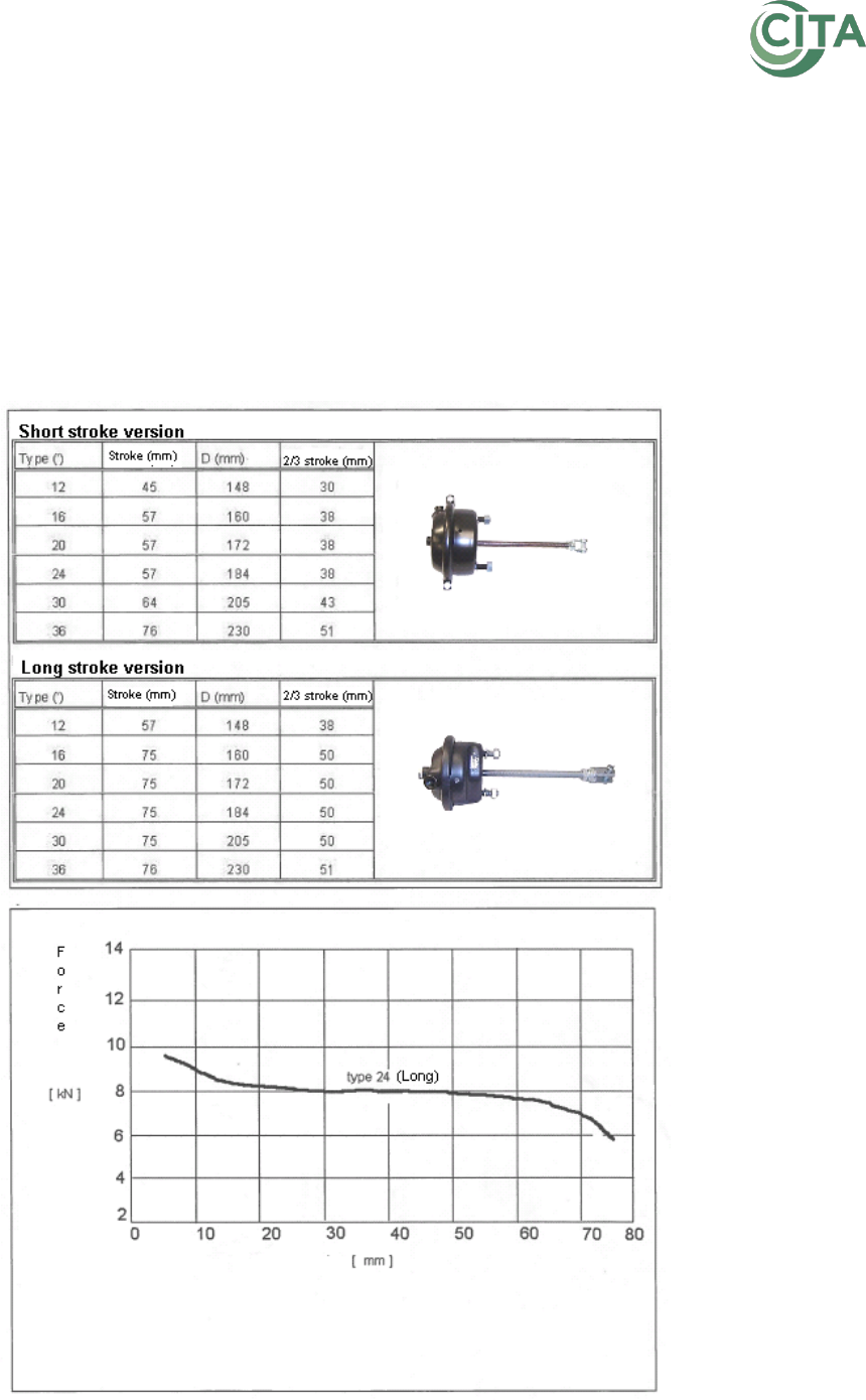
Recommendation No 8 | Brake testing in Periodic Technical Inspection
page 38/40
ANNEX 1
Slack Adjusters:
Incorrect installation;
Damaged or defective;
Seized or having abnormal movement.
Maximum movement for a drum brake:
From the rest position to the braked position the stroke of compressed air brake
cylinders must not be greater than 2/3 of the maximum stroke of the brake cylinder
concerned. (See table 1)
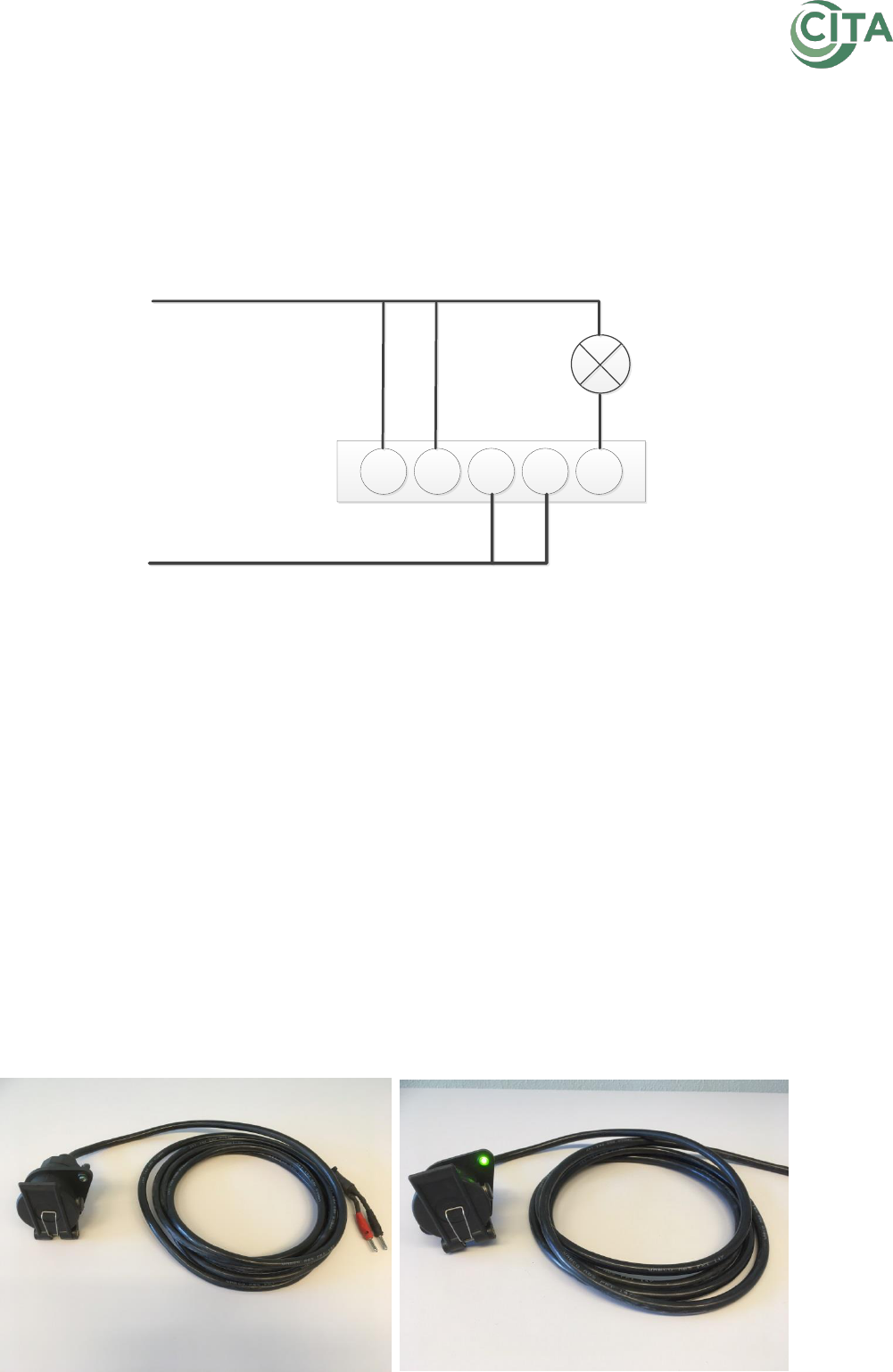
Recommendation No 8 | Brake testing in Periodic Technical Inspection
page 39/40
ANNEX 2
Example for a testing device to check the control light from a trailer ABS on ISO 7638
connection:
This device can be self-made according to the schedule below.
Connector
1 2 3 4 5
Control lamp
Battery +
Battery -
Battery + = 24 Volt connection
Battery - = Vehicle Mass
Connector = ABS/EBS connector on the trailer
Control Lamp = 24 V light bulb
Usage:
1. The connections 1, 2, 3, 4 and 5 must be combined into the ISO ABS/EBS-connector
on the Trailer.
2. Connect the ABS/EBS connector to the Trailer.
3. Connect Battery + to a 24 Volt connection in the vehicle or an external power
supply.
4. Connect Battery – to the vehicle mass or an external power supply.
5. The control Lamp must light up for a few seconds:
a. If the control Lamp goes out the system is OK.
b. If the control Lamp stays on, there is a DTC in the system.
An example:
