
Absorbed Dose Determination in
External Beam Radiotherapy
An International Code of Practice for Dosimetry
Based on Standards of Absorbed Dose to Water
Sponsored by the IAEA, WHO, PAHO and ESTRO
INTERNATIONAL ATOMIC ENERGY AGENCY, VIENNA, 2000
TTEECCHHNNIICCAALL RREEPPOORRTTSS SSEERRIIEESS NNoo..
398
ABSORBED DOSE DETERMINATION
IN EXTERNAL
BEAM RADIOTHERAPY
An International Code of Practice for Dosimetry
Based on Standards of Absorbed Dose to Water
© IAEA, 2000
Permission to reproduce or translate the information contained in this publica-
tion may be obtained by writing to the International Atomic Energy Agency,
Wagramer Strasse 5, P.O. Box 100, A-1400 Vienna, Austria.
Printed by the IAEA in Austria
December 2000
STI/DOC/010/398

ABSORBED DOSE DETERMINATION
IN EXTERNAL
BEAM RADIOTHERAPY
An International Code of Practice for Dosimetry
Based on Standards of Absorbed Dose to Water
TECHNICAL REPORTS SERIES No. 398
INTERNATIONAL ATOMIC ENERGY AGENCY
VIENNA, 2000
FOREWORD
The International Atomic Energy Agency published in 1987 an International
Code of Practice entitled Absorbed Dose Determination in Photon and Electron
Beams (IAEA Technical Reports Series No. 277 (TRS-277)), recommending proce-
dures to obtain the absorbed dose in water from measurements made with an ioniza-
tion chamber in external beam radiotherapy. A second edition of TRS-277 was
published in 1997 updating the dosimetry of photon beams, mainly kilovoltage
X rays. Another International Code of Practice for radiotherapy dosimetry entitled
‘The Use of Plane-Parallel Ionization Chambers in High Energy Electron and Photon
Beams’ (IAEA Technical Reports Series No. 381 (TRS-381)) was published in 1997
to further update TRS-277 and complement it with respect to the area of parallel-plate
ionization chambers. Both codes have proven extremely valuable for users involved
in the dosimetry of the radiation beams used in radiotherapy. In TRS-277 the calibra-
tion of the ionization chambers was based on primary standards of air kerma; this
procedure was also used in TRS-381, but the new trend of calibrating ionization
chambers directly in a water phantom in terms of absorbed dose to water was
introduced.
The development of primary standards of absorbed dose to water for high
energy photon and electron beams, and improvements in radiation dosimetry
concepts, offer the possibility of reducing the uncertainty in the dosimetry of radio-
therapy beams. The dosimetry of kilovoltage X rays, as well as that of proton and
heavy ion beams, interest in which has grown considerably in recent years, can also
be based on these standards. Thus a coherent dosimetry system based on standards of
absorbed dose to water is possible for practically all radiotherapy beams. Many
Primary Standard Dosimetry Laboratories (PSDLs) already provide calibrations in
terms of absorbed dose to water at the radiation quality of
60
Co gamma rays. Some
laboratories have extended calibrations to high energy photon and electron beams or
are in the stage of developing the necessary techniques for these modalities.
Following the recommendations in 1996 of the IAEA Standing Advisory Group
Scientific Committee of the IAEA (WHO) SSDL Network, a Co-ordinated Research
Project was undertaken during 1997–1999 with the task of producing a new interna-
tional Code of Practice based on standards of absorbed dose to water. The Code is
also endorsed by the World Health Organization, the Pan American Health
Organization and the European Society of Therapeutic Radiology and Oncology
(ESTRO). The final draft was reviewed by representatives of the organizations
endorsing the Code and by a large number of scientists.
This Code of Practice fulfils the need for a systematic and internationally
unified approach to the calibration of ionization chambers in terms of absorbed dose
to water and to the use of these detectors in determining the absorbed dose to water

for the radiation beams used in radiotherapy. It provides a methodology for the deter-
mination of absorbed dose to water in the low, medium and high energy photon
beams, electron beams, proton beams and heavy ion beams used for external radia-
tion therapy. The officer at the IAEA responsible for this Code of Practice was
P. Andreo of the Division of Human Health.
EDITORIAL NOTE
Although great care has been taken to maintain the accuracy of information contained
in this publication, neither the IAEA nor its Member States assume any responsibility for
consequences which may arise from its use.
The use of particular designations of countries or territories does not imply any
judgement by the publisher, the IAEA, as to the legal status of such countries or territories, of
their authorities and institutions or of the delimitation of their boundaries.
The mention of names of specific companies or products (whether or not indicated as
registered) does not imply any intention to infringe proprietary rights, nor should it be
construed as an endorsement or recommendation on the part of the IAEA.
Reference to standards of other organizations is not to be construed as an endorsement
on the part of the IAEA.
ABOUT THIS BOOK
The structure of this Code of Practice differs from that of TRS-277 and more
closely resembles that of TRS-381 in that the practical recommendations and data for
each radiation type have been placed in an individual section devoted to that radiation
type. Each essentially forms a different Code of Practice and includes detailed proce-
dures and worksheets.
The Code is addressed to users provided with calibrations in terms of absorbed
dose to water traceable to a Primary Standard Dosimetry Laboratory. This category of
users is likely to become the large majority since most standard laboratories are
prepared to, or are planning to, supply calibrations in terms of absorbed dose to water
at the reference radiation qualities recommended in this Code of Practice. Users who
are not yet provided with calibrations in terms of absorbed dose to water may still
refer to the current air kerma based codes of practice, such as TRS-277 and TRS-381,
or adopt the present document using a calibration factor in terms of absorbed dose to
water derived from an air kerma calibration as described in the text. Whatever proce-
dure is employed, the user is strongly advised to verify exactly what physical quantity
has been selected for the calibration of the reference dosimeter in order to apply the
correct formalism.
A list of abbreviations of organizations mentioned in this Code is given in
Section 1.7.
Every user is invited to critically test this Code of Practice and submit
comments to:
Head, Dosimetry and Medical Radiation Physics Section,
Division of Human Health,
International Atomic Energy Agency,
Wagramer Strasse 5,
P.O. Box 100,
A-1400 Vienna, Austria
E-mail: [email protected]g
Fax: +43–1–26007
CONTENTS
1. INTRODUCTION . . . . . . . . . . . . . . . . . . . . . . . . . . . . . . . . . . . . . . . . . 1
1.1. Background . . . . . . . . . . . . . . . . . . . . . . . . . . . . . . . . . . . . . . . . . . 1
1.2. Advantages of a Code of Practice based on standards
of absorbed dose to water . . . . . . . . . . . . . . . . . . . . . . . . . . . . . . . 5
1.2.1. Reduced uncertainty . . . . . . . . . . . . . . . . . . . . . . . . . . . . . 5
1.2.2. A more robust system of primary standards . . . . . . . . . . . . 6
1.2.3. Use of a simple formalism . . . . . . . . . . . . . . . . . . . . . . . . 7
1.3. Types of radiation and range of beam qualities . . . . . . . . . . . . . . . 7
1.4. Practical use of this Code of Practice . . . . . . . . . . . . . . . . . . . . . . 8
1.5. Expression of uncertainties . . . . . . . . . . . . . . . . . . . . . . . . . . . . . . 9
1.6. Quantities and symbols . . . . . . . . . . . . . . . . . . . . . . . . . . . . . . . . . 9
1.7. Abbreviations of organizations . . . . . . . . . . . . . . . . . . . . . . . . . . . 14
2. FRAMEWORK . . . . . . . . . . . . . . . . . . . . . . . . . . . . . . . . . . . . . . . . . . . 15
2.1. The International Measurement System . . . . . . . . . . . . . . . . . . . . . 15
2.1.1. The IAEA/WHO network of SSDLs . . . . . . . . . . . . . . . . . 16
2.2. Standards of absorbed dose to water . . . . . . . . . . . . . . . . . . . . . . . 17
3.N
D,w
BASED FORMALISM . . . . . . . . . . . . . . . . . . . . . . . . . . . . . . . . . 21
3.1. Formalism . . . . . . . . . . . . . . . . . . . . . . . . . . . . . . . . . . . . . . . . . . . 21
3.1.1. Reference conditions . . . . . . . . . . . . . . . . . . . . . . . . . . . . . 21
3.1.2. Influence quantities . . . . . . . . . . . . . . . . . . . . . . . . . . . . . . 22
3.2. Correction for the radiation quality of the beam, k
Q,Q
o
. . . . . . . . . 22
3.2.1. A modified k
Q,Q
o
for electron beam cross-calibrations . . . . 24
3.3. Relation to N
K
based codes of practice . . . . . . . . . . . . . . . . . . . . . 26
4. IMPLEMENTATION . . . . . . . . . . . . . . . . . . . . . . . . . . . . . . . . . . . . . . . 27
4.1. General . . . . . . . . . . . . . . . . . . . . . . . . . . . . . . . . . . . . . . . . . . . . . 27
4.2. Equipment . . . . . . . . . . . . . . . . . . . . . . . . . . . . . . . . . . . . . . . . . . 29
4.2.1. Ionization chambers . . . . . . . . . . . . . . . . . . . . . . . . . . . . . 30
4.2.2. Measuring assembly . . . . . . . . . . . . . . . . . . . . . . . . . . . . . 38
4.2.3. Phantoms . . . . . . . . . . . . . . . . . . . . . . . . . . . . . . . . . . . . . 39
4.2.4. Waterproof sleeve for the chamber . . . . . . . . . . . . . . . . . . 41
4.2.5. Positioning of ionization chambers at the
reference depth . . . . . . . . . . . . . . . . . . . . . . . . . . . . . . . . . 41
4.3. Calibration of ionization chambers . . . . . . . . . . . . . . . . . . . . . . . . 44
4.3.1. Calibration in a
60
Co beam . . . . . . . . . . . . . . . . . . . . . . . . 44
4.3.2. Calibration in kilovoltage X rays . . . . . . . . . . . . . . . . . . . . 46
4.3.3. Calibration at other qualities . . . . . . . . . . . . . . . . . . . . . . . 46
4.4. Reference dosimetry in the user beam . . . . . . . . . . . . . . . . . . . . . . 48
4.4.1. Determination of the absorbed dose to water . . . . . . . . . . . 48
4.4.2. Practical considerations for measurements in
the user beam . . . . . . . . . . . . . . . . . . . . . . . . . . . . . . . . . . 48
4.4.3. Correction for influence quantities . . . . . . . . . . . . . . . . . . 49
5. CODE OF PRACTICE FOR
60
Co GAMMA
RAY BEAMS . . . . . . . . . . . . . . . . . . . . . . . . . . . . . . . . . . . . . . . . . . . . 57
5.1. General . . . . . . . . . . . . . . . . . . . . . . . . . . . . . . . . . . . . . . . . . . . . . 57
5.2. Dosimetry equipment . . . . . . . . . . . . . . . . . . . . . . . . . . . . . . . . . . 57
5.2.1. Ionization chambers . . . . . . . . . . . . . . . . . . . . . . . . . . . . . 57
5.2.2. Phantoms and chamber sleeves . . . . . . . . . . . . . . . . . . . . . 57
5.3. Beam quality specification . . . . . . . . . . . . . . . . . . . . . . . . . . . . . . 58
5.4. Determination of absorbed dose to water . . . . . . . . . . . . . . . . . . . . 58
5.4.1. Reference conditions . . . . . . . . . . . . . . . . . . . . . . . . . . . . . 58
5.4.2. Determination of absorbed dose under
reference conditions . . . . . . . . . . . . . . . . . . . . . . . . . . . . . 59
5.4.3. Absorbed dose at z
max
. . . . . . . . . . . . . . . . . . . . . . . . . . . . 60
5.5. Cross-calibration of field ionization chambers . . . . . . . . . . . . . . . . 60
5.6. Measurements under non-reference conditions . . . . . . . . . . . . . . . 60
5.6.1. Central axis depth dose distributions . . . . . . . . . . . . . . . . . 61
5.6.2. Output factors . . . . . . . . . . . . . . . . . . . . . . . . . . . . . . . . . . 61
5.7. Estimated uncertainty in the determination of
absorbed dose to water under reference conditions . . . . . . . . . . . . 62
5.8. Worksheet . . . . . . . . . . . . . . . . . . . . . . . . . . . . . . . . . . . . . . . . . . . 64
6. CODE OF PRACTICE FOR HIGH ENERGY PHOTON BEAMS . . . . . 66
6.1. General . . . . . . . . . . . . . . . . . . . . . . . . . . . . . . . . . . . . . . . . . . . . . 66
6.2. Dosimetry equipment . . . . . . . . . . . . . . . . . . . . . . . . . . . . . . . . . . 66
6.2.1. Ionization chambers . . . . . . . . . . . . . . . . . . . . . . . . . . . . . 66
6.2.2. Phantoms and chamber sleeves . . . . . . . . . . . . . . . . . . . . . 67
6.3. Beam quality specification . . . . . . . . . . . . . . . . . . . . . . . . . . . . . . 68
6.3.1. Choice of beam quality index . . . . . . . . . . . . . . . . . . . . . . 68
6.3.2. Measurement of beam quality . . . . . . . . . . . . . . . . . . . . . . 69
6.4. Determination of absorbed dose to water . . . . . . . . . . . . . . . . . . . . 70
6.4.1. Reference conditions . . . . . . . . . . . . . . . . . . . . . . . . . . . . . 70
6.4.2. Determination of absorbed dose under
reference conditions . . . . . . . . . . . . . . . . . . . . . . . . . . . . . 70
6.4.3. Absorbed dose at z
max
. . . . . . . . . . . . . . . . . . . . . . . . . . . . 71
6.5. Values for k
Q,Q
o
. . . . . . . . . . . . . . . . . . . . . . . . . . . . . . . . . . . . . . . 75
6.5.1. Chamber calibrated in
60
Co . . . . . . . . . . . . . . . . . . . . . . . . 75
6.5.2. Chamber calibrated in a series of photon
beam qualities . . . . . . . . . . . . . . . . . . . . . . . . . . . . . . . . . . 75
6.5.3. Chamber calibrated at Q
o
with generic
experimental k
Q,Q
o
values . . . . . . . . . . . . . . . . . . . . . . . . . 77
6.6. Cross-calibration of field ionization chambers . . . . . . . . . . . . . . . . 77
6.7. Measurements under non-reference conditions . . . . . . . . . . . . . . . 78
6.7.1. Central axis depth dose distributions . . . . . . . . . . . . . . . . . 78
6.7.2. Output factors . . . . . . . . . . . . . . . . . . . . . . . . . . . . . . . . . . 79
6.8. Estimated uncertainty in the determination of absorbed
dose to water under reference conditions . . . . . . . . . . . . . . . . . . . . 79
6.9. Worksheet . . . . . . . . . . . . . . . . . . . . . . . . . . . . . . . . . . . . . . . . . . . 81
7. CODE OF PRACTICE FOR HIGH-ENERGY ELECTRON BEAMS . . 84
7.1. General . . . . . . . . . . . . . . . . . . . . . . . . . . . . . . . . . . . . . . . . . . . . . 84
7.2. Dosimetry equipment . . . . . . . . . . . . . . . . . . . . . . . . . . . . . . . . . . 84
7.2.1. Ionization chambers . . . . . . . . . . . . . . . . . . . . . . . . . . . . . 84
7.2.2. Phantoms and chamber sleeves . . . . . . . . . . . . . . . . . . . . . 85
7.3. Beam quality specification . . . . . . . . . . . . . . . . . . . . . . . . . . . . . . 86
7.3.1. Choice of beam quality index . . . . . . . . . . . . . . . . . . . . . . 86
7.3.2. Measurement of beam quality . . . . . . . . . . . . . . . . . . . . . . 86
7.4. Determination of absorbed dose to water . . . . . . . . . . . . . . . . . . . . 88
7.4.1. Reference conditions . . . . . . . . . . . . . . . . . . . . . . . . . . . . . 88
7.4.2. Determination of absorbed dose under
reference conditions . . . . . . . . . . . . . . . . . . . . . . . . . . . . . 89
7.4.3. Absorbed dose at z
max
. . . . . . . . . . . . . . . . . . . . . . . . . . . . 90
7.5. Values for k
Q,Q
o
. . . . . . . . . . . . . . . . . . . . . . . . . . . . . . . . . . . . . . . 90
7.5.1. Chamber calibrated in
60
Co . . . . . . . . . . . . . . . . . . . . . . . . 90
7.5.2. Chamber calibrated at a series of
electron beam qualities . . . . . . . . . . . . . . . . . . . . . . . . . . . 90
7.6. Cross-calibration of ionization chambers . . . . . . . . . . . . . . . . . . . . 94
7.6.1. Cross-calibration procedure . . . . . . . . . . . . . . . . . . . . . . . . 94
7.6.2. Subsequent use of a cross-calibrated chamber . . . . . . . . . . 95
7.7. Measurements under non-reference conditions . . . . . . . . . . . . . . . 98
7.7.1. Central axis depth dose distributions . . . . . . . . . . . . . . . . . 98
7.7.2. Output factors . . . . . . . . . . . . . . . . . . . . . . . . . . . . . . . . . . 101
7.8. Use of plastic phantoms . . . . . . . . . . . . . . . . . . . . . . . . . . . . . . . . 101
7.8.1. Scaling of depths . . . . . . . . . . . . . . . . . . . . . . . . . . . . . . . . 102
7.8.2. Plastic phantoms for beam quality specification . . . . . . . . 102
7.8.3. Plastic phantoms for absorbed dose determination at z
ref
. . 103
7.8.4. Plastic phantoms for depth dose distributions . . . . . . . . . . 103
7.9. Estimated uncertainty in the determination of absorbed
dose to water under reference conditions . . . . . . . . . . . . . . . . . . . . 104
7.10. Worksheet . . . . . . . . . . . . . . . . . . . . . . . . . . . . . . . . . . . . . . . . . . . 107
8. CODE OF PRACTICE FOR LOW ENERGY
KILOVOLTAGE X RAY BEAMS . . . . . . . . . . . . . . . . . . . . . . . . . . . . . 110
8.1. General . . . . . . . . . . . . . . . . . . . . . . . . . . . . . . . . . . . . . . . . . . . . . 110
8.2. Dosimetry equipment . . . . . . . . . . . . . . . . . . . . . . . . . . . . . . . . . . 111
8.2.1. Ionization chambers . . . . . . . . . . . . . . . . . . . . . . . . . . . . . 111
8.2.2. Phantoms . . . . . . . . . . . . . . . . . . . . . . . . . . . . . . . . . . . . . 112
8.3. Beam quality specification . . . . . . . . . . . . . . . . . . . . . . . . . . . . . . 112
8.3.1. Choice of beam quality index . . . . . . . . . . . . . . . . . . . . . . 112
8.3.2. Measurement of beam quality . . . . . . . . . . . . . . . . . . . . . . 114
8.4. Determination of absorbed dose to water . . . . . . . . . . . . . . . . . . . . 115
8.4.1. Reference conditions . . . . . . . . . . . . . . . . . . . . . . . . . . . . . 115
8.4.2. Determination of absorbed dose under
reference conditions . . . . . . . . . . . . . . . . . . . . . . . . . . . . . 115
8.5. Values for k
Q,Q
o
. . . . . . . . . . . . . . . . . . . . . . . . . . . . . . . . . . . . . . . 116
8.6. Measurements under non-reference conditions . . . . . . . . . . . . . . . 117
8.6.1. Central axis depth dose distributions . . . . . . . . . . . . . . . . . 117
8.6.2. Output factors . . . . . . . . . . . . . . . . . . . . . . . . . . . . . . . . . . 117
8.7. Estimated uncertainty in the determination of
absorbed dose to water under reference conditions . . . . . . . . . . . . 118
8.8. Worksheet . . . . . . . . . . . . . . . . . . . . . . . . . . . . . . . . . . . . . . . . . . . 120
9. CODE OF PRACTICE FOR MEDIUM ENERGY
KILOVOLTAGE X RAY BEAMS . . . . . . . . . . . . . . . . . . . . . . . . . . . . . 122
9.1. General . . . . . . . . . . . . . . . . . . . . . . . . . . . . . . . . . . . . . . . . . . . . . 122
9.2. Dosimetry equipment . . . . . . . . . . . . . . . . . . . . . . . . . . . . . . . . . . 123
9.2.1. Ionization chambers . . . . . . . . . . . . . . . . . . . . . . . . . . . . . 123
9.2.2. Phantoms and chamber sleeves . . . . . . . . . . . . . . . . . . . . . 124
9.3. Beam quality specification . . . . . . . . . . . . . . . . . . . . . . . . . . . . . . 125
9.3.1. Choice of beam quality index . . . . . . . . . . . . . . . . . . . . . . 125
9.3.2. Measurement of beam quality . . . . . . . . . . . . . . . . . . . . . . 126
9.4. Determination of absorbed dose to water . . . . . . . . . . . . . . . . . . . . 127
9.4.1. Reference conditions . . . . . . . . . . . . . . . . . . . . . . . . . . . . . 127
9.4.2. Determination of absorbed dose under
reference conditions . . . . . . . . . . . . . . . . . . . . . . . . . . . . . 127
9.5. Values for k
Q,Q
o
. . . . . . . . . . . . . . . . . . . . . . . . . . . . . . . . . . . . . . . 127
9.6. Measurements under non-reference conditions . . . . . . . . . . . . . . . 129
9.6.1. Central axis depth dose distributions . . . . . . . . . . . . . . . . . 129
9.6.2. Output factors . . . . . . . . . . . . . . . . . . . . . . . . . . . . . . . . . . 131
9.7. Estimated uncertainty in the determination of
absorbed dose to water under reference conditions . . . . . . . . . . . . 131
9.8. Worksheet . . . . . . . . . . . . . . . . . . . . . . . . . . . . . . . . . . . . . . . . . . . 133
10. CODE OF PRACTICE FOR PROTON BEAMS . . . . . . . . . . . . . . . . . . 135
10.1. General . . . . . . . . . . . . . . . . . . . . . . . . . . . . . . . . . . . . . . . . . . . . . 135
10.2. Dosimetry equipment . . . . . . . . . . . . . . . . . . . . . . . . . . . . . . . . . . 137
10.2.1. Ionization chambers . . . . . . . . . . . . . . . . . . . . . . . . . . . . . 137
10.2.2. Phantoms and chamber sleeves . . . . . . . . . . . . . . . . . . . . . 137
10.3. Beam quality specification . . . . . . . . . . . . . . . . . . . . . . . . . . . . . . 138
10.3.1. Choice of beam quality index . . . . . . . . . . . . . . . . . . . . . . 138
10.3.2. Measurement of beam quality . . . . . . . . . . . . . . . . . . . . . . 139
10.4. Determination of absorbed dose to water . . . . . . . . . . . . . . . . . . . . 140
10.4.1. Reference conditions . . . . . . . . . . . . . . . . . . . . . . . . . . . . . 140
10.4.2. Determination of absorbed dose under
reference conditions . . . . . . . . . . . . . . . . . . . . . . . . . . . . . 141
10.5. Values for k
Q,Q
o
. . . . . . . . . . . . . . . . . . . . . . . . . . . . . . . . . . . . . . . 141
10.6. Measurements under non-reference conditions . . . . . . . . . . . . . . . 141
10.6.1. Central axis depth dose distributions . . . . . . . . . . . . . . . . . 145
10.6.2. Output factors . . . . . . . . . . . . . . . . . . . . . . . . . . . . . . . . . . 146
10.6.3. Use of plastic phantoms for relative dosimetry . . . . . . . . . 146
10.7. Estimated uncertainty in the determination of
absorbed dose to water under reference conditions . . . . . . . . . . . . 148
10.8. Worksheet . . . . . . . . . . . . . . . . . . . . . . . . . . . . . . . . . . . . . . . . . . . 149
11. CODE OF PRACTICE FOR HEAVY ION BEAMS . . . . . . . . . . . . . . . 151
11.1. General . . . . . . . . . . . . . . . . . . . . . . . . . . . . . . . . . . . . . . . . . . . . . 151
11.2. Dosimetry equipment . . . . . . . . . . . . . . . . . . . . . . . . . . . . . . . . . . 154
11.2.1. Ionization chambers . . . . . . . . . . . . . . . . . . . . . . . . . . . . . 154
11.2.2. Phantoms and chamber sleeves . . . . . . . . . . . . . . . . . . . . . 155
11.3. Beam quality specification . . . . . . . . . . . . . . . . . . . . . . . . . . . . . . 156
11.4. Determination of absorbed dose to water . . . . . . . . . . . . . . . . . . . . 156
11.4.1. Reference conditions . . . . . . . . . . . . . . . . . . . . . . . . . . . . . 156
11.4.2. Determination of absorbed dose under
reference conditions . . . . . . . . . . . . . . . . . . . . . . . . . . . . . 157
11.5. Values for k
Q,Q
o
. . . . . . . . . . . . . . . . . . . . . . . . . . . . . . . . . . . . . . . 157
11.6. Measurements under non-reference conditions . . . . . . . . . . . . . . . 158
11.7. Estimated uncertainty in the determination of
absorbed dose to water under reference conditions . . . . . . . . . . . . 160
11.8. Worksheet . . . . . . . . . . . . . . . . . . . . . . . . . . . . . . . . . . . . . . . . . . . 162
APPENDIX I. RELATION BETWEEN N
K
AND N
D,w
BASED
CODES OF PRACTICE . . . . . . . . . . . . . . . . . . . . . . . . . . . 165
I.1.
60
Co and high energy photon and electron beams . . . . . . . . . . . . . 165
I.1.1. A summary of notations used for calibration factors . . . . . 169
I.1.2. Comparison of D
w
determinations . . . . . . . . . . . . . . . . . . . 169
I.2. Kilovoltage X ray beams . . . . . . . . . . . . . . . . . . . . . . . . . . . . . . . . 172
APPENDIX II. CALCULATION OF k
Q,Q
o
AND ITS UNCERTAINTY . . . . 174
II.1. General . . . . . . . . . . . . . . . . . . . . . . . . . . . . . . . . . . . . . . . . . . . . . 174
II.2.
60
Co gamma radiation . . . . . . . . . . . . . . . . . . . . . . . . . . . . . . . . . . 175
II.2.1. Value for s
w,air
in
60
Co . . . . . . . . . . . . . . . . . . . . . . . . . . . . 175
II.2.2. Value for W
air
in
60
Co . . . . . . . . . . . . . . . . . . . . . . . . . . . . 175
II.2.3. Values for p
Q
in
60
Co . . . . . . . . . . . . . . . . . . . . . . . . . . . . 175
II.2.4. Summary of values and uncertainties in
60
Co . . . . . . . . . . 178
II.3. High energy photon beams . . . . . . . . . . . . . . . . . . . . . . . . . . . . . . 178
II.3.1. Values for s
w,air
in high energy photon beams . . . . . . . . . . 178
II.3.2. Value for W
air
in high energy photon beams . . . . . . . . . . . 178
II.3.3. Values for p
Q
in high energy photon beams . . . . . . . . . . . . 181
II.3.4. Summary of uncertainties in high energy photon beams . . 183
II.4. Electron beams . . . . . . . . . . . . . . . . . . . . . . . . . . . . . . . . . . . . . . . 185
II.4.1. Values for s
w,air
in electron beams . . . . . . . . . . . . . . . . . . . 185
II.4.2. Value for W
air
in electron beams . . . . . . . . . . . . . . . . . . . . 186
II.4.3. Values for p
Q
in electron beams . . . . . . . . . . . . . . . . . . . . 186
II.4.4. Summary of uncertainties in electron beams . . . . . . . . . . . 189
II.5. Proton beams . . . . . . . . . . . . . . . . . . . . . . . . . . . . . . . . . . . . . . . . 190
II.5.1. Values for s
w,air
in proton beams . . . . . . . . . . . . . . . . . . . . 190
II.5.2. Value for W
air
in proton beams . . . . . . . . . . . . . . . . . . . . . 192
II.5.3. Values for p
Q
in proton beams . . . . . . . . . . . . . . . . . . . . . . 192
II.5.4. Summary of uncertainties in proton beams . . . . . . . . . . . . 193
II.6. Heavy ion beams . . . . . . . . . . . . . . . . . . . . . . . . . . . . . . . . . . . . . . 194
II.6.1. Value for s
w,air
in heavy ion beams . . . . . . . . . . . . . . . . . . 194
II.6.2. Value for W
air
in heavy ion beams . . . . . . . . . . . . . . . . . . . 196
II.6.3. Value for p
Q
in heavy ion beams . . . . . . . . . . . . . . . . . . . . 196
II.6.4. Summary of uncertainties in heavy ion beams . . . . . . . . . . 196
APPENDIX III. PHOTON BEAM QUALITY SPECIFICATION . . . . . . . . . 198
III.1. Overview of common photon beam quality specifiers . . . . . . . . . . 198
III.2. Advantages and disadvantages of TPR
20,10
. . . . . . . . . . . . . . . . . . 200
III.3. Advantages and disadvantages of PDD(10)
x
. . . . . . . . . . . . . . . . . 203
III.4. Concluding remarks . . . . . . . . . . . . . . . . . . . . . . . . . . . . . . . . . . . 208
APPENDIX IV. EXPRESSION OF UNCERTAINTIES . . . . . . . . . . . . . . . . . 210
IV.1. General considerations on errors and uncertainties . . . . . . . . . . . . 210
IV.2. Type A standard uncertainties . . . . . . . . . . . . . . . . . . . . . . . . . . . . 211
IV.3. Type B standard uncertainties . . . . . . . . . . . . . . . . . . . . . . . . . . . . 212
IV.4. Combined and expanded uncertainties . . . . . . . . . . . . . . . . . . . . . . 213
REFERENCES . . . . . . . . . . . . . . . . . . . . . . . . . . . . . . . . . . . . . . . . . . . . . . . . 215
CONTRIBUTORS TO DRAFTING AND REVIEW . . . . . . . . . . . . . . . . . . . . 226
RELATED IAEA PUBLICATIONS . . . . . . . . . . . . . . . . . . . . . . . . . . . . . . . . 229

1
1. INTRODUCTION
1.1. BACKGROUND
In its Report 24 on ‘Determination of Absorbed Dose in a Patient Irradiated by
Beams of X or Gamma Rays in Radiotherapy Procedures’, the International
Commission on Radiation Units and Measurements (ICRU) [1] concluded that
“although it is too early to generalize, the available evidence for certain types of
tumour points to the need for an accuracy of ±5% in the delivery of an absorbed dose
to a target volume if the eradication of the primary tumour is sought”. The ICRU
continues, “Some clinicians have requested even closer limits such as ±2%, but at
the present time (in 1976) it is virtually impossible to achieve such a standard”.
These statements were made in a context where uncertainties were estimated at the
95% confidence level, and have been interpreted as if they correspond to approxi-
mately two standard deviations. Thus the requirement for an accuracy of 5% in the
delivery of absorbed dose would correspond to a combined uncertainty of 2.5% at
the level of one standard deviation. Today it is considered that a goal in dose delivery
to the patient based on such an accuracy requirement is too strict and the figure
should be increased to about one standard deviation of 5%, but there are no definite
recommendations in this respect.
1
The requirement for an accuracy of ±5% could,
on the other hand, also be interpreted as a tolerance of the deviation between the pre-
scribed dose and the dose delivered to the target volume. Modern radiotherapy has
confirmed, in any case, the need for high accuracy in dose delivery if new tech-
niques, including dose escalation in 3-D conformal radiotherapy, are to be applied.
Emerging technologies in radiotherapy, for example modern diagnostic tools for the
determination of the target volume, 3-D commercial treatment planning systems and
advanced accelerators for irradiation, can only be fully utilized if there is high
accuracy in dose determination and delivery.
The various steps between the calibration of ionization chambers in terms of
the quantity air kerma, K
air
, at the standardizing dosimetry laboratories and the
1
Several studies have concluded that for certain types of tumors the combined standard
uncertainty in dose delivery should be smaller than 3.3% or 3.5% [2–4], “even if in many cases
larger values are acceptable and in some special cases even smaller values should be aimed
at” [3]. It has also been stated that taking into account the uncertainties in dose calculation
algorithms, a more appropriate limit for the combined standard uncertainty of the dose
delivered to the target volume would be around 5% [4, 5].

2
determination of absorbed dose to water, D
w
, at hospitals using dosimetry protocols
based on the factor
2
N
D,air
(or N
gas
) introduce undesirable uncertainties into the
realization of D
w
. Many factors are involved in the dosimetric chain that starts with a
calibration factor in terms of air kerma, N
K
, measured in air using a
60
Co beam and
ends with the absorbed dose to water, D
w
, measured in water in clinical beams.
Uncertainties in the chain arise mainly from conversions performed by the user at the
hospital, for instance the well known k
m
and k
att
factors used in most codes of practice
and dosimetry protocols [8–19]. Uncertainties associated with the conversion of N
K
to N
D,air
(or N
gas
) mean that in practice the starting point of the calibration of clinical
beams already involves a considerable uncertainty [20]. The estimation of uncertain-
ties given in previous IAEA Codes of Practice [17, 21] showed that the largest
contribution to the uncertainty during beam calibration arises from the different phys-
ical quantities involved and the large number of steps performed, yielding standard
uncertainties of up to 3% or 4%. Even if more recent uncertainty estimates [22, 23]
have lowered these figures, the contribution from the first steps in the radiotherapy
dosimetry chain still do not comply with the demand for low uncertainty to minimize
the final uncertainty in patient dose delivery.
Reich [24] proposed the calibration of therapy level dosimeters in terms of
absorbed dose to water, stressing the advantages of using the same quantity and
experimental conditions as the user. The current status of the development of pri-
mary standards of absorbed dose to water for high energy photons and electrons, and
the improvement in radiation dosimetry concepts and data available, have made it
possible to reduce the uncertainty in the calibration of radiation beams. The devel-
opment of standards of absorbed dose to water at Primary Standard Dosimetry
Laboratories (PSDLs) has been a major goal pursued by the Comité Consultatif pour
les Etalons de Mesure des Rayonnements Ionisants (Section I) [25]. Measurements
of absorbed dose to graphite using graphite calorimeters were developed first and
2
The standard ISO 31-0 [6], ‘Quantities and Units’, has provided guidelines with regard
to the use of the term ‘coefficient’, which should be used for a multiplier possessing dimen-
sions, and ‘factor’, which should be reserved for a dimensionless multiplier. The more recent
standard IEC-60731 [7] is not consistent, however, with the International Organization for
Standardization (ISO) vocabulary and still provides a definition of the term ‘calibration factor’.
Although this Code of Practice continues using the term calibration factor, users should be
aware of the possibility of a change in terminology by standards laboratories in favour of cali-
bration coefficient.
continue to be used in many laboratories. This procedure was considered as an inter-
mediate step between air kerma and direct determination of the absorbed dose to
water, since absolute calorimetric measurements in water are more problematic.
Comparisons of determinations of absorbed dose to graphite were satisfactory and,
consequently, the development of standards of absorbed dose to water was under-
taken in some laboratories. Procedures to determine absorbed dose to water using
methods to measure appropriate base or derived quantities have considerably
improved at the PSDLs in the last decade. The well established procedures are the
ionization method, chemical dosimetry, and water and graphite calorimetry.
Although only the water calorimeter allows the direct determination of the absorbed
dose to water in a water phantom, the required conversion and perturbation factors
for the other procedures are now well known at many laboratories. These develop-
ments lend support to a change in the quantity used at present to calibrate ionization
chambers and provide calibration factors in terms of absorbed dose to water, N
D,w
,
for use in radiotherapy beams. Many PSDLs already provide N
D,w
calibrations at
60
Co gamma ray beams and some laboratories have extended these calibration pro-
cedures to high energy photon and electron beams; others are developing the neces-
sary techniques for such modalities.
At Secondary Standard Dosimetry Laboratories (SSDLs), calibration factors
from a PSDL or from the Bureau International des Poids et Mesures (BIPM) are
transferred to hospital users. For
60
Co gamma ray beams, most SSDLs can provide
users with a calibration factor in terms of absorbed dose to water without much exper-
imental effort, as all SSDLs have such beams. However, it is not possible for them, in
general, to supply experimentally determined calibration factors at high energy
photon and electron beams. Numerical calculations of a beam quality correction
factor, related to
60
Co, can, however, be performed which should be equivalent to
those obtained experimentally but with a larger uncertainty.
A major advance in radiotherapy over the last few years has been the increasing
use of proton and heavy ion irradiation facilities for radiation therapy. Practical
dosimetry in these fields is also based on the use of ionization chambers that may be
provided with calibrations both in terms of air kerma and in terms of absorbed dose
to water, therefore the dosimetry procedures developed for high energy photons and
electrons can also be applicable to protons and heavy ions. At the other extreme of the
range of available teletherapy beams lie kilovoltage X ray beams, and for these the
use of standards of absorbed dose to water was introduced in IAEA Technical Reports
Series No. 277 (TRS-277) [17]. However, for kilovoltage X rays there are, at present,
very few laboratories providing N
D,w
calibrations because most PSDLs have not yet
established primary standards of absorbed dose to water for such radiation qualities.
Nevertheless, N
D,w
calibrations in kilovoltage X ray beams may be provided by
PSDLs and SSDLs based on their standards of air kerma and one of the current
dosimetry protocols for X ray beams. Thus a coherent dosimetry system based on
3

standards of absorbed dose to water is now possible for practically all radiotherapy
beams [26] (see Fig. 1).
3
This new international Code of Practice for the determination of absorbed dose
to water in external beam radiotherapy, using an ionization chamber or a dosimeter
having an N
D,w
calibration factor, will be applicable in all hospitals and facilities pro-
viding radiation treatment of cancer patients. Even though the nature of these
4
3
For neutron therapy beams, the reference material to which the absorbed dose relates
is ICRU soft tissue [26]. This Code of Practice is based on the quantity absorbed dose to water.
Owing to the strong dependence of neutron interaction coefficients on neutron energy and
material composition, there is no straightforward procedure to derive absorbed dose to soft
tissue from absorbed dose to water. Moreover, neutron dosimetry is traditionally performed
with tissue equivalent ionization chambers, flushed with a tissue equivalent gas in order to
determine the absorbed dose in an homogeneous medium. Although it is possible to express the
resulting formalism [26] in terms of k
Q,Q
o
, for most ionization chamber types there is a lack of
data on the physical parameters which apply to the measurement of absorbed dose to water in
a neutron beam. Therefore, the dosimetry of the radiotherapy neutron beams is not dealt with
in this Code of Practice.
FIG. 1. Coherent dosimetry system based on standards of absorbed dose to water. Primary
standards based on water calorimetry, graphite calorimetry, chemical dosimetry and iono-
metry allow the calibration of ionization chambers in terms of absorbed dose to water, N
D,w
.
A single Code of Practice provides the methodology for the determination of absorbed dose to
water in the low, medium,
60
Co and high energy photon beams, electron beams, proton beams
and heavy ion beams used for external radiation therapy.

institutions may be widely different, this Code of Practice will serve as a useful doc-
ument to the medical physics and radiotherapy community and help achieve unifor-
mity and consistency in radiation dose delivery throughout the world. The Code of
Practice should also be of value to the IAEA/WHO network of SSDLs in improving
the accuracy and consistency of their dose determination, and thereby the standard-
ization of radiation dosimetry in the many countries which they serve.
1.2. ADVANTAGES OF A CODE OF PRACTICE BASED ON STANDARDS OF
ABSORBED DOSE TO WATER
Absorbed dose to water is the quantity of main interest in radiation therapy,
since this quantity relates closely to the biological effects of radiation. The advantages
of calibrations in terms of absorbed dose to water and dosimetry procedures using
these calibration factors have been presented by several authors [20, 27, 28] and are
described in detail in an ICRU report on photon dosimetry [29]. A summary of the
most relevant aspects is given below.
1.2.1. Reduced uncertainty
The drive towards an improved basis for dosimetry in radiotherapy has caused
PSDLs to devote much effort in the last two decades towards developing primary
standards of absorbed dose to water. The rationale for changing the basis of calibra-
tions from air kerma to absorbed dose to water was the expectation that the calibra-
tion of ionization chambers in terms of absorbed dose to water would considerably
reduce the uncertainty in determining the absorbed dose to water in radiotherapy
beams. Measurements based on calibration in air in terms of air kerma require
chamber dependent conversion factors to determine absorbed dose to water. These
conversion factors do not account for differences between individual chambers of a
particular type. In contrast, calibrations in terms of absorbed dose to water can be per-
formed under similar conditions to subsequent measurements in the user beam, so
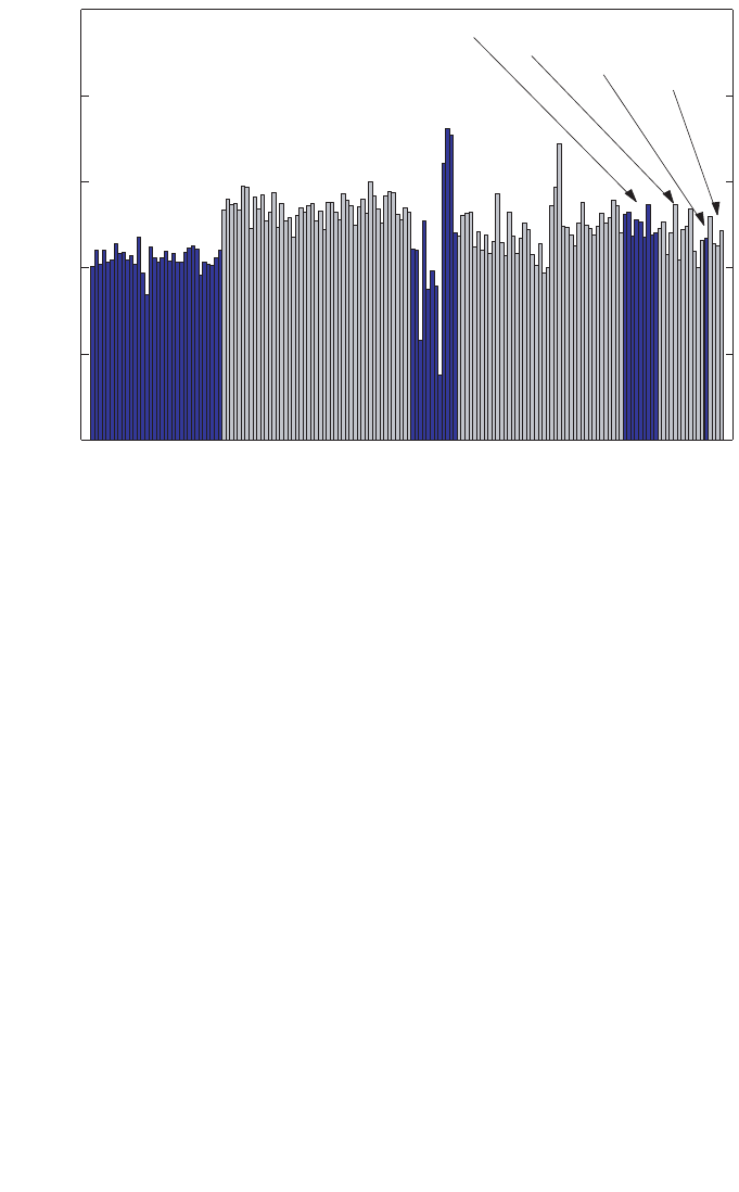
that the response of each individual chamber is taken into account. Figure 2 shows
chamber to chamber variations, demonstrated for a given chamber type by the lack of
constancy in the N
D,w
/N
K
ratio at
60
Co, for a large number of cylindrical ionization
chambers commonly used in radiotherapy dosimetry. For a given chamber type,
chamber to chamber differences of up to 0.8% have also been reported by the
BIPM [30]. The elimination of the uncertainty component caused by the assumption
that all chambers of a given type are identical is a justification for favouring direct
calibration of ionization chambers in terms of absorbed dose to water.
In principle, primary standards of absorbed dose to water can operate in both
60
Co beams and accelerator beams. Thus, for high energy photon and electron
5
radiation, an experimental determination of the energy dependence of ionization
chambers becomes available, resulting in reduced uncertainty owing to the effect of
beam quality. Similar conclusions can be drawn for therapeutic proton and heavy ion
beams, although primary standards of absorbed dose to water are not yet available at
these radiation qualities.
1.2.2. A more robust system of primary standards
Despite the fact that the quantity of interest in radiation dosimetry is absorbed
dose to water, most national, regional and international dosimetry recommendations
are based on the use of an air kerma calibration factor for an ionization chamber,
traceable to a national or international primary standard of air kerma for
60
Co gamma
radiation. Although international comparisons of these standards have exhibited very
good agreement, a substantial weakness prevails in that all such standards are based
on ionization chambers and are therefore subject to common errors. In addition,
depending on the method of evaluation, a factor related to the attenuation in the
6
1.07
1.08
1.09
1.10
1.11
1.12
N
NE 2561
and
NE 2611
NE 2571
NE 2581
PTW 30001
PTW 30002
PTW 30006
PTW 23333
D,w
/ N
K
PTW 30004
FIG. 2. The ratio of
60
Co calibration factors N
D,w
/N
K
is a useful indicator of the uniformity
within a given type of chamber [30]. Chamber to chamber variations, demonstrated by
differences in the ratio N
D,w
/N
K
for chambers of a given type, are shown for a large number
of cylindrical ionization chambers commonly used in radiotherapy dosimetry (see Table 3 for
a description of each chamber type). The large variation for NE 2581 chambers is considered
to be caused by the hygroscopic properties of the A-150 plastic walls (data measured in the
IAEA Dosimetry Laboratory).

chamber wall entering into the determination of the quantity air kerma has been found
to differ by up to 0.7% for some primary standards [31]. In contrast, primary
standards of absorbed dose to water are based on a number of different physical
principles. There are no assumptions or estimated correction factors common to all of
them. Therefore, good agreement among these standards (see Section 2.2) gives much
greater confidence in their accuracy.
1.2.3. Use of a simple formalism
The formalism given in Ref. [17] and in most national and international
dosimetry protocols for the determination of absorbed dose to water in radiotherapy
beams is based on the application of several coefficients, perturbation and other cor-
rection factors. This is because of the practical difficulty in making the conversion
from the free-air quantity air kerma to the in-phantom quantity absorbed dose to water.
This complexity is best demonstrated by considering the equations needed, and the
procedures for selecting the appropriate data. Reliable information about certain phys-
ical characteristics of the ionization chamber used is also required. Many of these data,
such as displacement correction factors and stopping-power ratios, are derived from
complex measurements or calculations based on theoretical models. A simplified pro-
cedure starting from a calibration factor in terms of absorbed dose to water, and
applying correction factors for all influence quantities, reduces the possibility of errors
in the determination of absorbed dose to water in the radiation beam. The simplicity of
the formalism in terms of absorbed dose to water becomes obvious when the general
equation for the determination of absorbed dose to water is considered (see Section 3).
1.3. TYPES OF RADIATION AND RANGE OF BEAM QUALITIES
This Code of Practice provides a methodology for the determination of
absorbed dose to water in the low, medium and high energy photon beams, electron
beams, proton beams and heavy ion beams used for external radiation therapy. The
ranges of radiation qualities covered in this report are given below (for a description
of the beam quality index see the corresponding sections):
(a) Low energy X rays with generating potentials up to 100 kV and HVL of 3 mm
Al (the lower limit is determined by the availability of standards);
4
7
4
The boundary between the two ranges for kilovoltage X rays is not strict and has an
overlap between 80 kV, 2 mm Al and 100 kV, 3 mm Al. In this overlap region, the methods for
absorbed dose determination given in Sections 8 or 9 are equally satisfactory, and whichever is
more convenient should be used.

(b) Medium energy X rays with generating potentials above 80 kV and HVL of
2 mm Al (see footnote 4);
(c)
60
Co gamma radiation;
(d) High energy photons generated by electrons with energies in the interval
1–50 MeV, with TPR
20,10
values between 0.50 and 0.84;
(e) Electrons in the energy interval 3–50 MeV, with a half-value depth, R
50
,
between 1 and 20 g/cm
2
;
(f) Protons in the energy interval 50–250 MeV, with a practical range, R
p
, between
0.25 and 25 g/cm
2
;
(g) Heavy ions with Z between 2 (He) and 18 (Ar) having a practical range in water,
R
p
, of 2 to 30 g/cm
2
(for carbon ions this corresponds to an energy range of
100 MeV/u to 450 MeV/u, where u is the atomic mass unit).
1.4. PRACTICAL USE OF THIS CODE OF PRACTICE
Emphasis has been given to making the practical use of this report as simple as
possible. The structure of this Code of Practice differs from that of TRS-277 [17] and
more closely resembles Technical Reports Series No. 381 (TRS-381) [21] in that the
practical recommendations and data for each radiation type have been placed in an
individual section devoted to that radiation type. Each essentially forms a different
Code of Practice, including detailed procedures and worksheets. The reader can per-
form a dose determination for a given beam by working through the appropriate sec-
tion; the search for procedures or tables contained in other parts of the document has
been reduced to a minimum. Making the various Codes of Practice independent and
self-contained has required an unavoidable repetition of some portions of text, but this
is expected to result in a publication which is simple and easy to use, especially for
users having access to a limited number of radiation types. The first four sections con-
tain general concepts that apply to all radiation types. Appendices provide a comple-
ment to the information supplied in the various sections.
Compared with previous codes of practice or dosimetry protocols based on
standards of air kerma (see Refs [17, 21]), the adoption of this Code of Practice will
introduce small differences in the value of the absorbed dose to water determined in
clinical beams. Detailed comparisons will be published in the open literature, and the
results are expected to depend on the type and quality of the beam and on the type of
ionization chamber. Where differences arise, it is important to notice that they might
be due to: (i) inaccuracies in the numerical factors and expressions (for example k
m
,
p
wall
, etc.) in the N
K
based method and, to a lesser extent, in this Code of Practice, and
(ii) the primary standards to which the calibrations in terms of air kerma and absorbed
dose to water are traceable. Even for
60
Co gamma radiation, which is generally better
8

characterized than other modalities, beam calibrations based on the two different
standards, K
air
and D
w
, differ by typically 1% (see Appendix I); the value derived
using this Code of Practice is considered to be the better estimate. Any conclusions
drawn from comparisons between protocols based on standards of air kerma and
absorbed dose to water must take account of the differences between primary stan-
dards.
1.5. EXPRESSION OF UNCERTAINTIES
The evaluation of uncertainties in this Code of Practice follows the guidance
given by the ISO [32]. Uncertainties of measurements are expressed as relative stan-
dard uncertainties and the evaluation of standard uncertainties is classified into type
A and type B. The method of evaluation of type A standard uncertainty is by statis-
tical analysis of a series of observations, whereas the method of evaluation of type B
standard uncertainty is based on means other than statistical analysis of a series of
observations. A practical implementation of the ISO recommendations, based on the
summaries provided in Refs [33] and [17], is given for completeness in Appendix IV
of this Code of Practice.
Estimates of the uncertainty in dose determination for the different radiation
types are given in the appropriate sections. Compared with estimates in previous
codes of practice, the present values are generally smaller. This arises from the greater
confidence in determinations of absorbed dose to water based on D
w
standards and,
in some cases, from a more rigorous analysis of uncertainties in accordance with the
ISO guidelines.
1.6. QUANTITIES AND SYMBOLS
Most of the symbols used in this Code of Practice are identical to those used in
Refs [17] and [21], and only a few are new in the context of standards of absorbed
dose to water. For completeness, a summary is provided here for all quantities of
relevance to the different methods used in this Code of Practice.
c
pl
Material dependent scaling factor to convert ranges and depths mea-
sured in plastic phantoms into the equivalent values in water. This
applies to electron, proton and heavy ion beams. Note that in this Code
of Practice the depths and ranges are defined in units of g/cm
2
, in con-
trast to their definition in cm in Ref. [21] for electron beams. As a
9

result, the values given for c
pl
in this Code for electrons differ from
those for C
pl
given in Ref. [21]. The use of lowercase for c
pl
denotes
this change.
csda Continuous slowing down approximation.
D
w,Q
Absorbed dose to water at the reference depth, z
ref
, in a water phantom
irradiated by a beam of quality Q. The subscript Q is omitted when the
reference beam quality is
60
Co. Unit: gray (Gy).
E
o
, E
z
Mean energy of an electron beam at the phantom surface and at depth
z, respectively. Unit: MeV.
h
pl
Material dependent fluence scaling factor to correct for the difference
in electron fluence in plastic compared with that in water at an equiva-
lent depth.
HVL Half-value layer, used as a beam quality index for low and medium
energy X ray beams.
k
i
General correction factor used in the formalism to correct for the effect
of the difference in the value of an influence quantity between the
calibration of a dosimeter under reference conditions in the standards
laboratory and the use of the dosimeter in the user facility under
different conditions.
k
elec
Calibration factor of an electrometer.
k
h
Factor to correct the response of an ionization chamber for the effect of
humidity if the chamber calibration factor is referred to dry air.
k
pol
Factor to correct the response of an ionization chamber for the effect of
a change in polarity of the polarizing voltage applied to the chamber.
k
Q,Q
o
Factor to correct for the difference between the response of an ioniza-
tion chamber in the reference beam quality Q
o
used for calibrating the
chamber and in the actual user beam quality Q. The subscript Q
o
is
omitted when the reference quality is
60
Co gamma radiation (i.e. the
reduced notation k
Q
always corresponds to the reference quality
60
Co).
k
s
Factor to correct the response of an ionization chamber for the lack of
complete charge collection (due to ion recombination).
k
TP
Factor to correct the response of an ionization chamber for the effect of
the difference that may exist between the standard reference tempera-
ture and pressure specified by the standards laboratory and the temper-
ature and pressure of the chamber in the user facility under different
environmental conditions.
M
Q
Reading of a dosimeter at quality Q, corrected for influence quantities
other than beam quality. Unit: C or rdg.
M
em
Reading of a dosimeter used as an external monitor. Unit: C or rdg.
(
µ
en
/
ρ
)m
1
,m
2
ratio of the mean mass energy absorption coefficients of materials m
1
and m
2
, averaged over a photon spectrum.
10

N
D,air
Absorbed dose to air chamber factor of an ionization chamber used in
air kerma based dosimetry protocols (cf. Refs [17, 21]). This is the N
gas
of Ref. [9]. The factor N
D,air
was called N
D
in Ref. [11] and in Ref. [17],
but the subscript ‘air’ was included in Ref. [21] to specify without
ambiguity that it refers to the absorbed dose to the air of the chamber
cavity. Care should be taken by the user to avoid confusing N
D,air
, or the
former N
D
, with the calibration factor in terms of absorbed dose to
water N
D,w
described below (see Appendix I). Unit: Gy/C or Gy/rdg.
N
D,w,Q
o
Calibration factor in terms of absorbed dose to water for a dosimeter at
a reference beam quality Q
o
. The product M
Q
o
N
D,w,Q
o
yields the
absorbed dose to water, D
w,Q
o
, at the reference depth z
ref
and in the
absence of the chamber. The subscript Q
o
is omitted when the reference
quality is a beam of
60
Co gamma rays (i.e. N
D,w
always corresponds to
the calibration factor in terms of absorbed dose to water in a
60
Co
beam). The factor N
D,w
was called N
D
in Ref. [9], where a relationship
between N
gas
and N
D
was given similar to that described in Section 3.3
and Appendix I. The symbol N
D
is also used in calibration certificates
issued by some standards laboratories and manufacturers instead of
N
D,w
. Users are strongly recommended to ascertain the physical quan-
tity used for the calibration of their detectors in order to avoid serious
mistakes.
5
Unit: Gy/C or Gy/rdg.
N
K,Q
o
Calibration factor in terms of air kerma for a dosimeter at a reference
beam quality Q
o
. Unit: Gy/C or Gy/rdg.
p
cav
Factor that corrects the response of an ionization chamber for effects
related to the air cavity, predominantly the in-scattering of electrons
that makes the electron fluence inside a cavity different from that in the
medium in the absence of the cavity.
p
cel
Factor that corrects the response of an ionization chamber for the effect
of the central electrode during in-phantom measurements in high
energy photon (including
60
Co), electron and proton beams. Note that
this factor is not the same as in Ref. [17], where the correction took into
account the global effect of the central electrode both during calibration
of the chamber in air in a
60
Co beam, and during subsequent measure-
ments in photon and electron beams in a phantom. To avoid ambigui-
ties, Ref. [21] called the correction factor used in Ref. [17] p
cel-gbl
,
11
5
The difference between N
D,air
and N
D,w
is close to the value of the stopping-power
ratio, water to air, in
60
Co gamma rays. A confusion in the meaning of the factors could
therefore result in an error in the dose delivered to patients of approximately 13% (see
Appendix I).

keeping the symbol p
cel
exclusively for in-phantom measurements (see
Appendix I).
PDD Percentage depth dose.
p
dis
Factor that accounts for the effect of replacing a volume of water with
the detector cavity when the reference point of the chamber
6
is taken to
be at the chamber centre. It is the alternative to the use of an effective
point of measurement of the chamber, P
eff
. For plane-parallel ioniza-
tion chambers, p
dis
is not required.
P
eff
The effective point of measurement of an ionization chamber. For the
standard calibration geometry, i. e. a radiation beam incident from one
direction, P
eff
is shifted from the position of the centre towards the
source by a distance which depends on the type of beam and chamber.
For plane-parallel ionization chambers P
eff
is usually assumed to be sit-
uated in the centre of the front surface of the air cavity.
7
The concept of
the effective point of measurement of a cylindrical ionization chamber
was used for all radiation types in Ref. [17], but in this Code of Practice
it is only used for electron and heavy ion beams. For other beams, ref-
erence dosimetry is based on positioning the reference point of the
chamber at the reference depth, z
ref
, where the dose is determined. The
reference point of an ionization chamber is specified for each radiation
type in the corresponding section.
p
Q
Overall perturbation factor for an ionization chamber for in-phantom
measurements at a beam quality Q. It is equal to the product of various
factors correcting for different effects, each correcting for small pertur-
bations; in practice these are p
cav
, p
cel
, p
dis
and p
wall
.
p
wall
Factor that corrects the response of an ionization chamber for the non-
medium equivalence of the chamber wall and any waterproofing
material.
Q General symbol to indicate the quality of a radiation beam. A subscript
‘o’, i.e. Q
o
, indicates the reference quality used for the calibration of an
ionization chamber or a dosimeter.
rdg Value, in arbitrary units, used for the reading of a dosimeter.
12
6
The reference point of a chamber is specified in this Code of Practice in each section
for each type of chamber. It usually refers to the point of the chamber specified by a calibra-
tion document to be that at which the calibration factor applies [33].
7
This assumption might fail if the chamber design does not follow certain requirements
regarding the ratio of cavity diameter to cavity height as well as that of guard ring width to
cavity height (see Ref. [21]).

R
50
Half-value depth in water (in g/cm
2
), used as the beam quality index for
electron beams.
R
p
Practical range (in g/cm
2
) for electron, proton and heavy ion beams.
R
res
Residual range (in g/cm
2
) for proton beams.
r
cyl
Cavity radius of a cylindrical ionization chamber.
SAD Source–axis distance.
SCD Source–chamber distance.
SOBP Spread-out Bragg peak.
SSD Source–surface distance.
s
m,air
Stopping-power ratio medium to air, defined as the ratio of the mean
restricted mass stopping powers of materials m and air, averaged over
an electron spectrum. For all high energy radiotherapy beams in this
Code of Practice, except for heavy ion beams, stopping-power ratios
are of the Spencer–Attix type with a cut-off energy ∆ = 10 keV (see
Ref. [11]).
TMR Tissue–maximum ratio.
TPR
20,10
Tissue–phantom ratio in water at depths of 20 and 10 g/cm
2
, for a field
size of 10 cm × 10 cm and an SCD of 100 cm, used as the beam quality
index for high energy photon radiation.
u
c
Combined standard uncertainty of a quantity.
W
air
The mean energy expended in air per ion pair formed.
z
max
Depth of maximum dose (in g/cm
2
).
z
ref
Reference depth (in g/cm
2
) for in-phantom measurements. When
specified at z
ref
, the absorbed dose to water refers to D
w,Q
at the inter-
section of the beam central axis with the plane defined by z
ref
.
13
14
1.7. ABBREVIATIONS OF ORGANIZATIONS
The following abbreviations are used in this report to refer to different organi-
zations involved in radiation dosimetry:
ARPANSA Australian Radiation Protection and Nuclear Safety Agency, Australia
BEV Bundesamt für Eich- und Vermessungswesen, Austria
BIPM Bureau International des Poids et Mesures
CCEMRI(I) Comité Consultatif pour les Etalons de Mesure des Rayonnements
Ionisants (Section I) (Consultative Committee for Standards of
Ionizing Radiation). Since September 1997, the CCEMRI and its
sections have been renamed CCRI.
CCRI(I) Comité Consultatif des Rayonnements Ionisants (Section I)
(Consultative Committee for Ionizing Radiation)
CIPM Comité International des Poids et Mesures
ENEA- Ente per le Nuove Tecnologie, l’Energia e l’Ambiente, Instituto
INMRI Nazionale di Metrologia delle Radiazioni Ionizzanti, Italy
ICRU International Commission on Radiation Units and Measurements
IEC International Electrotechnical Commission
IMS International Measurement System
ISO International Organization for Standardization
LPRI Laboratoire Primaire de Métrologie des Rayonnements Ionisants,
France
NIST National Institute of Standards and Technology, USA
NPL National Physical Laboratory, United Kingdom
NRC National Research Council, Canada
NRL National Radiation Laboratory, New Zealand
OIML Organisation Internationale de Métrologie Légale
PTB Physikalisch-Technische Bundesanstalt, Germany
15
2. FRAMEWORK
2.1. THE INTERNATIONAL MEASUREMENT SYSTEM
The International Measurement System for radiation metrology provides the
framework for consistency in radiation dosimetry by disseminating to users calibrated
radiation instruments which are traceable to primary standards (see Fig. 3).
The BIPM was set up by the Metre Convention (originally signed in 1875), with
48 States as members as of 31 December 1997 [34]. It serves as the international
centre for metrology, with its laboratory and offices in Sèvres (France), with the aim
of ensuring worldwide uniformity in matters relating to metrology. In radiation
dosimetry, the PSDLs of many States of the Metre Convention have developed pri-
mary standards for radiation measurements (see Table 1) that are compared with those
of the BIPM and other PSDLs. However, worldwide there are only some twenty
countries with PSDLs involved in radiation dosimetry and they cannot calibrate the
very large number of radiation dosimeters that are in use all over the world. Those
national laboratories that maintain primary standards calibrate the secondary
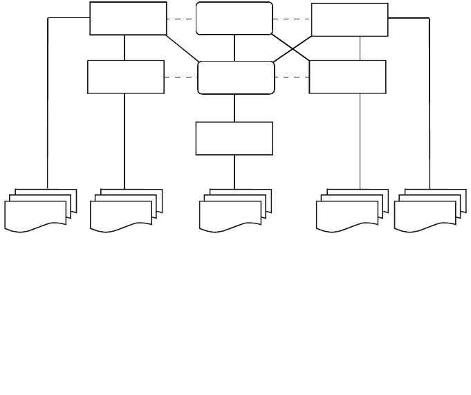
FIG. 3. The International Measurement System (IMS) for radiation metrology, where the
traceability of user reference instruments to primary standards is achieved either by direct
calibration in a Primary Standard Dosimetry Laboratory (PSDL) or, more commonly, in a
Secondary Standard Dosimetry Laboratory (SSDL) with direct link to the BIPM, a PSDL or to
the IAEA/WHO network of SSDLs. Most SSDLs from countries not members of the Metre
Convention achieve the traceability of their standards through the IAEA. The dashed lines
indicate intercomparisons of primary and secondary standards.
PSDLs
SSDLs
SSDLs
PSDLs
SSDLs
BIPM
IAEA
Users Users Users Users Users

16
standards of SSDLs (see Table 1), which in turn calibrate the reference instruments
of users (some PSDLs also calibrate the reference instruments of users).
2.1.1. The IAEA/WHO network of SSDLs
The main role of the SSDLs is to bridge the gap between PSDLs and the users
of ionizing radiation by enabling the transfer of dosimeter calibrations from the
TABLE 1. CLASSIFICATION OF INSTRUMENTS AND STANDARDS
LABORATORIES (adapted from Ref. [33])
Classification of instruments Standards laboratories
Primary standard Primary Standard Dosimetry Laboratory (PSDL)
An instrument of the highest A national standardizing laboratory designated
metrological quality that permits by the government for the purpose of
determination of the unit of a quantity developing, maintaining and improving primary
from its definition, the accuracy of standards in radiation dosimetry.
which has been verified by
comparison with the comparable Secondary Standard Dosimetry Laboratory (SSDL)
standards of other institutions at A dosimetry laboratory designated by the competent
the same level. authorities to provide calibration services, and
which is equipped with at least one secondary
Secondary standard standard that has been calibrated against a primary
An instrument calibrated by standard.
comparison with a primary standard
National standard
A standard recognized by an official
national decision as the basis for
fixing the value in a country of all
other standards of the given quantity.
Reference instrument
An instrument of the highest
metrological quality available at a given
location, from which measurements
at that location are derived.
Field instrument
A measuring instrument used for
routine measurements whose
calibration is related to the reference
instrument.

17
primary standard to user instruments [35]. In 1976, a network of SSDLs was estab-
lished as a joint effort by the IAEA and WHO in order to disseminate calibrations to
users by providing the link between users and primary standards, mainly for countries
that are not members of the Metre Convention. By 2000, the network included 73 lab-
oratories and 6 SSDL national organizations in 61 IAEA Member States, of which
over half are in developing countries. The SSDL network also includes 20 affiliated
members, among them the BIPM, several national PSDLs, the ICRU and other inter-
national organizations that provide support to the network [36].
As the organizer of the network, the IAEA has the responsibility to verify that
the services provided by the SSDL member laboratories follow internationally
accepted metrological standards (including traceability for radiation protection
instruments). The first step in this process is the dissemination of dosimeter calibra-
tions from the BIPM or PSDLs through the IAEA to the SSDLs. In the next step,
follow-up programmes and dose quality audits are implemented by the IAEA for the
SSDLs to guarantee that the standards disseminated to users are kept within the levels
of accuracy required by the IMS [36].
One of the principal goals of the SSDL network in the field of radiotherapy
dosimetry is to guarantee that the dose delivered to patients undergoing radiotherapy
treatment is within internationally accepted levels of accuracy. This is accomplished
by ensuring that the calibrations of instruments provided by the SSDLs are correct,
emphasizing the participation of the SSDLs in quality assurance programmes for
radiotherapy, promoting the contribution of the SSDLs to support dosimetry quality
audits in therapy centres and assisting if needed in performing the calibration of
radiotherapy equipment in hospitals.
2.2. STANDARDS OF ABSORBED DOSE TO WATER
There are three basic methods currently used for the absolute determination of
absorbed dose to water: calorimetry, chemical dosimetry and ionization dosimetry. At
present, these are the only methods that are sufficiently accurate to form the basis of
primary standards for measurements of absorbed dose to water [29]. The PSDLs have
developed various experimental approaches to establish standards of absorbed dose to
water. These standards are described briefly and the results of international
comparisons of absorbed dose to water are presented below.
In most PSDLs the primary standards of absorbed dose to water operate in a
60
Co gamma ray beam and in some PSDLs the standards of absorbed dose to water
operate also at other radiation qualities such as high energy photons, electrons and
kilovoltage X rays. Primary standards operating in
60
Co gamma ray beams or in
photon and electron beams produced by accelerators are based on one of the
following methods below.

18
— The ionization chamber primary standard consists of a graphite cavity chamber
with accurately known chamber volume, designed to fulfil as far as possible the
requirements of a Bragg–Gray detector. The chamber is placed in a water
phantom and the absorbed dose to water at the reference point derived from the
mean specific energy imparted to the air of the cavity [37].
— The graphite calorimeter developed by Domen and Lamperti [38] is used with
slight modifications by several PSDLs to determine the absorbed dose to
graphite in a graphite phantom. The conversion to absorbed dose to water at the
reference point in a water phantom may be performed in different ways, for
example by application of the photon fluence scaling theorem or by measure-
ments based on the cavity ionization theory [39, 40].
— The water calorimeter offers a more direct determination of the absorbed dose
to water at the reference point in a water phantom. The sealed water system
[41, 42] consists of a small glass vessel containing high purity water and a ther-
mistor detector unit. Water purity is important because the heat defect of water
is strongly influenced by impurities. With the sealed water arrangement high
purity water can be saturated with various gases to create a mixture for which
the heat defect has a well defined and stable value.
— The water calorimeter with Fricke transfer dosimeter [43] is based on the mea-
surement of the average temperature increase induced by the absorption of high
energy photons. The water is stirred continuously and the absorbed dose to
water averaged over the volume of the vessel is determined. The Fricke solu-
tion is calibrated by irradiation under the same conditions and the absorbed
dose to water at the reference point in a water phantom is obtained using the
Fricke dosimeter as the transfer standard.
— The Fricke standard of absorbed dose to water determines the response of the
Fricke solution using the total absorption of an electron beam in the solu-
tion [44]. Knowing the electron energy, the beam current and the absorbing
mass accurately, the total absorbed energy can be determined and related to the
change in absorbance of the Fricke solution as measured spectrophotometri-
cally. The absorbed dose to water at the reference point in a water phantom is
obtained using the Fricke dosimeter as the transfer standard.
The methods outlined above are not applied at PSDLs to primary standards for
use in kilovoltage X ray beams. Absolute measurements for the determination of
absorbed dose to water in kilovoltage X ray beams have been based so far almost
exclusively on the use of extrapolation ionization chambers [45].
Comparisons of primary standards of absorbed dose to water have been carried
out over the past decade [29, 46, 47], whereas comparisons of air kerma primary stan-
dards have a much longer history. The results of comparisons at the BIPM in terms of
absorbed dose to water for
60
Co gamma radiation are given in Ref. [48] (see
19
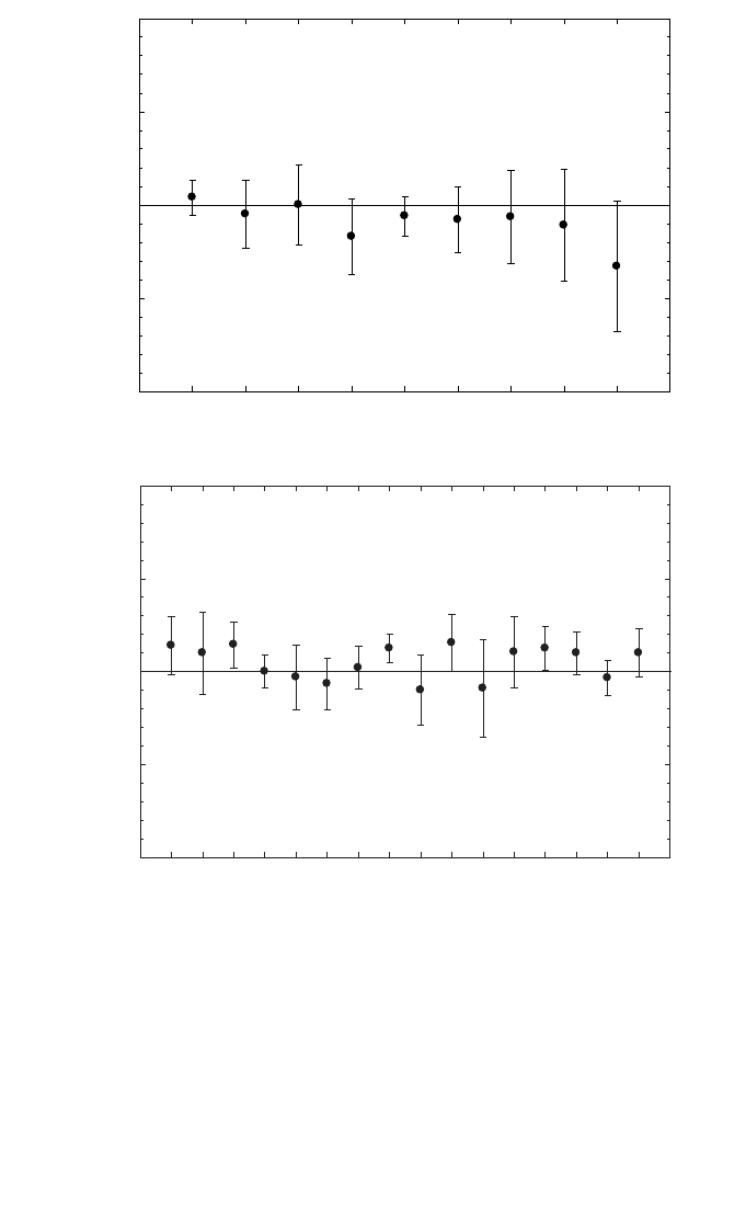
FIG. 4. (a) Results of comparisons of standards of absorbed dose to water at the BIPM in the
60
Co beam [48]. The results are relative to the BIPM determination and are those for the most
recent comparison for each national metrology institute, the oldest dating from 1989. The
uncertainty bars represent the relative standard uncertainty of the determination of absorbed
dose to water at each institute. Information on the primary standards used by the PSDLs is
given in Table 2. (b) Results of comparisons of standards for air kerma at the BIPM in the
60
Co
beam [48]. The results are relative to the BIPM determination and are those for the most
recent comparison for each national metrology institute. The uncertainty bars represent the
relative standard uncertainty of the air kerma determination at each institute.
D
w
(PSDL) / D
w
(BIPM)
0.98
0.99
1.00
1.01
1.02
ARPANSA
Australia
BEV
Austria
BIPM ENEA
Italy
LPRI
France
NIST
USA
NPL
UK
NRC
Canada
PTB
Germany
(a)
K
air
K
air
(PSDL) / (BIPM)
0.98
0.99
1.00
1.01
1.02
ARPANSA
Australia
BARC
India
BEV
Austria
BIPM
ENEA
Italy
GUM
Poland
LNMRI
Brazil
LPRI
France
NIST
USA
NMi
Nether-
lands
NPL
UK
NRC
Canada
OMH
Hun-
gary
PTB
Ger-
many
CMI
Czech
R.
NIIM
Russian
Fed.
(b)

20
Fig. 4(a)). The agreement is well within the relative standard uncertainties estimated
by each PSDL. Comparisons of air-kerma primary standards for
60
Co gamma radia-
tion exhibit a similar standard deviation (see Fig. 4(b)). However, the air kerma
primary standards of all PSDLs are graphite cavity ionization chambers and the
conversion and correction factors used are strongly correlated. As can be seen from
Table 2, the PSDLs involved in the comparisons of absorbed dose to water use
different methods which have uncorrelated, or very weakly correlated, uncertainties
and constitute a system which is more robust than the primary standards based on air
kerma and is less susceptible to unknown systematic influences.
TABLE 2. PRIMARY STANDARDS USED IN THE COMPARISONS OF
ABSORBED DOSE TO WATER AT THE BIPM
PSDL Primary standard PSDL Primary standard
BIPM Ionization chamber NIST (USA) Sealed water calorimeter
ARPANSA Graphite calorimeter NPL (UK) Graphite calorimeter
(Australia)
BEV (Austria) Graphite calorimeter NRC (Canada) Sealed water calorimeter
ENEA (Italy) Graphite calorimeter PTB (Germany) Fricke dosimeter
LPRI (France) Graphite calorimeter

21
3. N
D,w
BASED FORMALISM
The formalism for the determination of absorbed dose to water in high energy
photon and electron beams using an ionization chamber or a dosimeter calibrated in
terms of absorbed dose to water in a
60
Co beam has been given in detail by
Hohlfeld [27]. Complementary work on this topic and extensions of the formalism
have been developed by Andreo [20] and Rogers [28]. The procedure for the deter-
mination of absorbed dose to water based on standards of absorbed dose to water has
been implemented in the national dosimetry recommendations [49–51]. It was also
included in the IAEA Code of Practice for plane-parallel ionization chambers [21].
3.1. FORMALISM
The absorbed dose to water at the reference depth z
ref
in water for a reference
beam of quality Q
o
and in the absence of the chamber is given by
D
w,Q
o
= M
Q
o
N
D,w,Q
o
(1)
where M
Q
o
is the reading of the dosimeter under the reference conditions used in the
standards laboratory and N
D,w,Q
o
is the calibration factor in terms of absorbed dose to
water of the dosimeter obtained from a standards laboratory. In most clinical
situations the measurement conditions do not match the reference conditions used in
the standards laboratory. This may affect the response of the dosimeter and it is then
necessary to differentiate between the reference conditions used in the standards
laboratory and the clinical measurement conditions.
3.1.1. Reference conditions
The calibration factor for an ionization chamber irradiated under reference con-
ditions is the ratio of the conventional true value of the quantity to be measured to the
indicated value.
8
Reference conditions are described by a set of values of influence
8
The conventional true value of a quantity is the value attributed to a particular quantity
and accepted, sometimes by convention, as having an uncertainty appropriate for a given pur-
pose. The conventional true value is sometimes called assigned value, best estimate of the
value, conventional value or reference value [52]. At a given laboratory or hospital, the value
realized by a reference standard may be taken as a conventional true value and, frequently, the
mean of a number of results of measurements of a quantity is used to establish a conventional
true value.

22
quantities for which the calibration factor is valid without further correction factors.
The reference conditions for calibrations in terms of absorbed dose to water are, for
example, the geometrical arrangement (distance and depth), the field size, the mate-
rial and dimensions of the irradiated phantom, and the ambient temperature, pressure
and relative humidity.
3.1.2. Influence quantities
Influence quantities are defined as quantities that are not the subject of the mea-
surement, but yet influence the quantity under measurement. They may be of different
nature as, for example, pressure, temperature and polarization voltage; they may arise
from the dosimeter (e.g. ageing, zero drift, warm-up); or may be quantities related to
the radiation field (e.g. beam quality, dose rate, field size, depth in a phantom).
In calibrating an ionization chamber or a dosimeter, as many influence quanti-
ties as practicable are kept under control. However, many influence quantities cannot
be controlled, for example air pressure and humidity, and dose rate in
60
Co gamma
radiation. It is possible to correct for the effect of these influence quantities by
applying appropriate factors. Assuming that influence quantities act independently
from each other, a product of correction factors can be applied, Πk
i
, where each
correction factor k
i
is related to one influence quantity only. The independence of k
i
holds for the common corrections for pressure and temperature, polarity, collection
efficiency, etc., which are dealt with in Section 4.
A departure from the reference beam quality Q
o
used to calibrate an ionization
chamber can also be treated as an influence quantity. Measurements at radiation qual-
ities other than the reference quality Q
o
therefore require a correction factor. In this
Code of Practice this is treated explicitly by the factor k
Q,Q
o
which is not included in
the k
i
above; the correction for the radiation beam quality is described in detail below.
3.2. Correction for the radiation quality of the beam, k
Q,Q
o
When a dosimeter is used in a beam of quality Q different from that used in its
calibration, Q
o
, the absorbed dose to water is given by
D
w,Q
= M
Q
N
D,w,Q
o
k
Q,Q
o
(2)
where the factor k
Q,Q
o
corrects for the effects of the difference between the reference
beam quality Q
o
and the actual user quality Q, and the dosimeter reading M
Q
has been
corrected to the reference values of influence quantities, other than beam quality, for
which the calibration factor is valid.

23
The beam quality correction factor k
Q,Q
o
is defined as the ratio, at the qualities
Q and Q
o
, of the calibration factors in terms of absorbed dose to water of the ioniza-
tion chamber
(3)
The most common reference quality Q
o
used for the calibration of ionization
chambers is
60
Co gamma radiation, in which case the symbol k
Q
is used in this Code
of Practice for the beam quality correction factor. In some PSDLs high energy photon
and electron beams are directly used for calibration purposes and the symbol k
Q,Q
o
is
used in those cases.
Ideally, the beam quality correction factor should be measured directly for
each chamber at the same quality as the user beam. However, this is not achievable
in most standards laboratories. Such measurements can be performed only in
laboratories with access to the appropriate beam qualities. For this reason the tech-
nique is at present restricted to a few PSDLs in the world. The procedure requires
the availability of an energy independent dosimetry system, such as a calorimeter,
operating at these qualities. A related problem is the difficulty in reproducing in a
standards laboratory beam qualities identical to those produced by clinical
accelerators [53].
When no experimental data are available, or it is difficult to measure k
Q,Q
o
directly for realistic clinical beams, in many cases the correction factors can be
calculated theoretically. Where Bragg–Gray theory can be applied, an expression for
k
Q,Q
o
can be derived comparing Eq. (2) with the N
D,air
formalism used in the IAEA
Codes of Practice [17, 21] and other dosimetry protocols. A general expression for
k
Q,Q
o
has been given in Refs [20, 54]
(4)
which is valid for all types of high energy beams and includes ratios, at the qualities
Q and Q
o
, of Spencer–Attix water/air stopping-power ratios, s
w,air
, of the mean energy
expended in air per ion pair formed, W
air
,
9
and of the perturbation factors p
Q
. The
()
(
)
()
()
air
air
air air
o
o
o
o
w,
QQQ
Q,Q
w, Q
Q
Q
s
W
p
k =
sWp
==
o
ooo
w,Q Q
D,w,Q
Q,Q
D,w,Q w,Q Q
D/M
N
k
ND/M
9
It should be noticed that W
air
, as well as s
w,air
, should be averaged over the complete
spectra of particles present. This is an important limitation in the case of heavy charged parti-
cles, where the determination of all possible particle spectra is a considerable undertaking.

24
overall perturbation factors p
Q
and p
Q
o
include all departures from the ideal
Bragg–Gray detector conditions, i.e. p
wall,
p
cav
, p
cel
and p
dis
. These perturbation
factors have been defined in Section 1.6.
In therapeutic electron and photon beams, the general assumption of (W
air
)
Q
=
(W
air
)
Q
o
10
yields the simpler equation for k
Q,Q
o
(5)
which depends only on quotients of water to air stopping-power ratios and perturba-
tion factors at the beam qualities Q and Q
o
. The only chamber specific factors
involved are the perturbation correction factors p
Q
and p
Q
o
. It should be emphasized,
however, that when comparing experimental and theoretical determinations of k
Q,Q
o
it is the full Eq. (4) that is relevant, rather than the approximate Eq. (5). The possible
energy variation of W
air
, as suggested by some experimental evidence (cf. Ref. [55]),
makes it necessary to use the approximate symbol (≈) in the latter expression.
When the reference quality Q
o
is
60
Co gamma radiation, values of the product
(s
w,air
)
Q
o
p
Q
o
in the denominator of Eq. (4) are given in Appendix II for cylindrical
ionization chambers listed in this Code of Practice. These values have been used in
the calculation of all k
Q,Q
o
factors given in the different sections of this Code of
Practice when they are normalized to
60
Co; the symbol k
Q
is used in those cases.
In the case of low and medium energy X ray beams, Bragg–Gray conditions do
not apply and therefore Eq. (4) can not be used. In addition, the chamber to chamber
variation in response is usually rather large (see Sections 8 and 9). For these radiation
qualities the formalism is based exclusively on the use of directly measured N
D,w,Q
or
k
Q,Q
o
factors for individual user chambers.
3.2.1. A modified k
Q,Q
o
for electron beam cross-calibrations
For dosimeters that are used in electron beams, when the calibration quality Q
o
is
60
Co, the situation is the same as discussed previously. For a user electron beam
quality Q, the beam quality correction factor k
Q
is given by Eq. (4).
An alternative to this is the direct calibration of chambers in electron beams,
although this option has little application at present because of the limited availability
()
()
air
air
o
o
w,
QQ
Q,Q
Q
w,
o
Q
s
p
k
p
s
ª
10
Note that this is the same assumption as for the non-dependence of N
D,air
on the
quality of the beam (see Ref. [17]).

25
of such calibrations. However, the ongoing development of electron beam primary
standards will enable calibration at a series of electron beam qualities. From these
calibration factors, a series of measured k
Q,Q
o
factors may be derived following the
procedure given in Section 7.5.2 (the same procedure is used for chambers calibrated
directly in high energy photons and in low and medium energy X rays).
A third possibility, which in the absence of direct calibration in electron beams
is the preferred choice, is the cross-calibration of a plane-parallel chamber against a
calibrated cylindrical chamber in a high energy electron beam of quality Q
cross
. The
factors k
Q,Q
cross
, which allow the subsequent use of this chamber in an electron beam
of quality Q, are non-trivial because the cross-calibration quality Q
cross
is not unique
and so for each chamber type a two dimensional table of k
Q,Q
cross
factors is required.
However, it is possible to present the required data in a single table by intro-
ducing an arbitrary electron beam quality Q
int
which acts as an intermediate between
the cross-calibration quality Q
cross
and the user quality Q (no measurements are made
at Q
int
, it is a tool to simplify the presentation of the data). The required k
Q,Q
cross
factor is evaluated as the ratio of the factors k
Q,Q
int
and k
Q
cross,
Q
int
:
(6)
The factor (k
Q
cross,
Q
int
)
–1
corrects the actual chamber calibration factor
N
D,w,Q
cross
into a calibration factor which applies at the intermediate quality Q
int
. The
factor k
Q,Q
int
corrects this latter calibration factor into one which applies at Q so that
the general Eq. (2) for D
w,Q
can be applied.
The expressions for k
Q,Q
int
and k
Q
cross
,Q
int
follow from Eq. (5), from which it is
clear that the stopping-power ratios and perturbation factors at Q
int
will cancel in
Eq. (6). Thus the value chosen for Q
int
is arbitrary and in this Code of Practice is
chosen as R
50
= 7.5 g/cm
2
, where R
50
is the beam quality index in electron beams (see
Section 7). Values for k
Q,Q
int
and k
Q
cross,
Q
int
calculated on this basis are given in
Table 19 of Section 7.6.1 for a series of chamber types.
The data of Table 19 highlight another advantage of this approach. For a given
Q and Q
cross
, the value for k
Q
cross,
Q
int
is the same for all well guarded plane-parallel
chamber types. For cylindrical chamber types it depends only on the chamber radius
r
cyl
. The chosen value for Q
int
minimizes the differences for cylindrical chambers
of different r
cyl
over the range of beam qualities for which cylindrical chambers are
used. This value for Q
int
(R
50
= 7.5 g/cm
2
) is also consistent with Ref. [51], so
that the same measured or calculated values for k
Q,Q
int
and k
Q
cross,
Q
int
may be
used in Eq. (6).
Note that the above method may also be used for plane-parallel or cylindrical
chambers calibrated at a standards laboratory at a single electron beam quality Q
o
.
int
int
cross
cross
Q,Q
Q,Q
Q,Q
k
k=
k

26
3.3. RELATION TO N
K
BASED CODES OF PRACTICE
The connection between the N
K
–N
D,air
formalism (used, for example, in
Refs [17, 21]) and the present N
D,w
formalism is established for high energy beams
by the relationship
(7)
where Q
o
is the reference quality (
60
Co gamma rays in previous codes of practice) and
p
Q
o
the overall perturbation factor given by
(8)
The meaning of the different perturbation factors has been described in Section 1.6,
where it was emphasized that p
cel
refers exclusively to in-phantom measurements and
should not be confused with the symbol used in Ref. [17] to account for the combined
effect of the central electrode in air and in phantom measurements. A similar
relationship can be established for low and medium energy X rays. Details on the
comparison between the two formalisms are given in Appendix I.
Although the use of a calculated N
D,w,Q
o
calibration factor is not recommended,
this option could be used during an interim period aiming at the practical
implementation of this Code of Practice using existing air kerma calibrations. This will
be the most common procedure for kilovoltage X rays until standards of absorbed dose
to water become more widely disseminated. It is emphasized, however, that calculated
N
D,w,Q
o
calibration factors are not traceable to primary standards of absorbed dose to
water.
A calculated N
D,w,Q
o
can also be used to verify that therapy beam calibrations
based on the two formalisms, N
D,w
and N
K
, yield approximately the same absorbed
dose to water under reference conditions (see Appendix I for details). Should this not
be the case, the reasons for the discrepancy should be carefully investigated before
switching to the N
D,w
method.
[]
dis wall cav cel
Q
Q
o
o
p=pppp
air air
QQ
D,w,Q D, w,
ooo
N=N(s)p

27
4. IMPLEMENTATION
4.1. GENERAL
Efforts in PSDLs have concentrated on providing calibrations in terms of
absorbed dose to water of ionization chambers in
60
Co gamma ray beams, and to a
lesser extent in high energy photon and electron beams [46, 56–59]. Depending on
the standards laboratory, users may be provided with N
D,w,Q
o
calibrations according
to different options. These options are clarified here in order to avoid the incorrect use
of this Code of Practice.
(a) The first approach is to provide users with a calibration factor at a reference
beam quality Q
o
, usually
60
Co. For additional qualities the calibration at the ref-
erence quality is supplied together with directly measured beam quality correc-
tion factors k
Q,Q
o
for that particular chamber at specific beam qualities Q. Only
laboratories having radiation sources and standards operating at different beam
qualities can provide directly measured values of k
Q,Q
o
for these qualities. The
main advantage of this approach is that the individual chamber response in a
water phantom irradiated by various beam types and qualities is intrinsically
taken into account. A possible limitation, common to option (b) below, resides
in the difference between the beam qualities used at the standards laboratory
and at the user facility, which is of special relevance for high energy beams (cf.
Ref. [53]) and whose influence is still the subject of studies at some PSDLs.
(b) An alternative approach, which is in practical terms identical to the one
described above and differs only in the presentation of the data, is to provide a
series of N
D,w,Q
calibrations of the user ionization chamber at beam qualities Q.
There is, however, an advantage in presenting the data by normalizing all
calibration factors to a single calibration factor N
D,w,Q
o
, together with directly
measured values of k
Q,Q
o
. Once directly measured values of k
Q,Q
o
for a partic-
ular chamber have been obtained, it may not be necessary for the user to recal-
ibrate the chamber at all qualities Q, but only at the single reference quality Q
o
.
The quality dependence of that chamber can be verified less often by calibra-
tion at all qualities.
11
Furthermore, this single reference quality calibration does
not need to be performed at the same laboratory where the k
Q,Q
o
values were
measured (usually a PSDL).
(c) In the third approach users can be provided with a N
D,w,Q
o
calibration factor for
the ionization chamber, most commonly at the reference quality
60
Co, and
11
See Section 4.3 for recommendations on the frequency of dosimeter calibrations.

28
theoretically derived beam quality correction factors k
Q,Q
o
for that chamber
type which must be applied for other beam qualities. This method ignores
chamber to chamber variations in response with the energy of a given chamber
type, and calculations rely on chamber specifications provided by
manufacturers.
(d) A fourth approach, offered by some standards laboratories, is to provide a
single measured N
D,w,Q
o
for a given chamber, obtained at a selected reference
quality, together with generic
12
experimental values of k
Q,Q
o
for that ionization
chamber type. This option does not take into account possible chamber to
chamber variations within a given chamber type. Furthermore, there are
currently only limited experimental data on k
Q,Q
o
for most commercial cham-
bers. This approach has much in common with option (c) above and if, for a
given chamber type, the theoretical values of k
Q,Q
o
are verified experimentally
in a standards laboratory for a large sample of chambers, the theoretical values
of k
Q,Q
o
can be assumed to correspond to a mean value.
On the basis of these descriptions, the following recommendations are given for
compliance with this Code of Practice.
(1) Approach (a), or its equivalent (b), are the preferred alternatives, although it is
acknowledged that for beam qualities other than
60
Co such possibilities are at
present restricted to a few PSDLs.
(2) Approach (c) is recommended for those users who do not have access to k
Q
or
k
Q,Q
o
values directly measured at various beam qualities in a standards
laboratory. The use of
60
Co as the reference quality for determining N
D,w
is
particularly appropriate for SSDLs, where the possibility of having an acceler-
ator is remote. This approach is the most common practice today and favours
the use of theoretical k
Q
factors (i.e. k
Q,Q
o
with
60
Co used as Q
o
) determined
according to Eqs (4) or (5).
(3) Approach (d) is an alternative option to (c) only when k
Q
or k
Q,Q
o
values have
been obtained by a standards laboratory from a large sample of ionization
chambers and the standard deviation of chamber to chamber differences is
small. This is usually the case for secondary standard quality chambers (see
Ref. [7]) such as those measured by the National Physical Laboratory in the
United Kingdom (see Fig. 5) [60]. Generic experimental k
Q
or k
Q,Q
o
values not
determined by a standards laboratory are not recommended.
12
In the present context, generic stands for factors common to a specific ionization
chamber type, supplied by a given manufacturer.
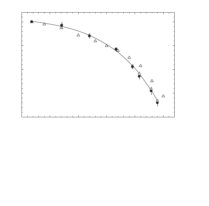
29
(4) Low and medium energy X ray dosimetry must be based on approaches (a) or
(b) with the range of values of Q chosen to be as similar as possible to the
qualities of the beams that will be used clinically.
(5) As long as there are restricted possibilities for establishing experimental N
D,w,Q
factors by standards laboratories in proton and heavy ion beams, the theoretical
approach (c) is the only recommendation to be used for such beams.
4.2. EQUIPMENT
Only ionometric measurements are considered in this Code of Practice for
reference dosimetry. The requirements on equipment follow closely those in
Refs [17, 21], as well as IEC Standard 60731 [7] for dosimeters with ionization
chambers. The use of these documents, although developed for photon and electron
radiation, can be extended to the other types of radiation fields included in this Code
FIG. 5. Mean values of k
Q
at various photon beam qualities measured at the National Physical
Laboratory (NPL) in the UK for secondary standard ionization chambers of the type NE 2561
(open circles) and NE 2611 (filled circles) [60]. The solid line is a sigmoidal fit to the experi-
mental data. The uncertainty bars represent chamber to chamber variations, determined as the
standard deviations of samples of 13 NE 2561 (upper half) and 11 NE 2611 (lower half) cham-
bers. The values of k
Q
are normalized to a TPR
20,10
of 0.568 (
60
Co beam at the NPL). Calculated
values of k
Q
for these chambers given in Table 14 are included for comparison (triangles); note
that the calculated values do not distinguish between the two types of chamber.
Photon beam quality, Q (TPR
20,10
)
0.55 0.60 0.65 0.70 0.75 0.80
k
Q
0.96
0.97
0.98
0.99
1.00

30
of Practice. The present section provides only general requirements on equipment;
specific details on instrumentation that apply to each radiation type will be discussed
in the relevant section.
An ionometric dosimeter system for radiotherapy contains the following
components:
(a) One or more ionization chamber assemblies, which include the electrical fitting
and any permanently attached cable, intended for different purposes (e.g. dif-
ferent radiation qualities);
(b) A measuring assembly (electrometer), often separately calibrated in terms of
charge or current per scale division;
(c) One or more phantoms with waterproof sleeves;
(d) The dosimeter system should also include one or more stability check devices.
4.2.1. Ionization chambers
A cylindrical ionization chamber type may be used for the calibration of radio-
therapy beams of medium energy X rays above 80 kV and an HVL of 2 mm
aluminium,
6O
Co gamma radiation, high energy photon beams, electron beams with
energy above 10 MeV approximately, and therapeutic proton and heavy ion beams.
This type of chamber is very convenient for measurements at these radiation qualities
as it is robust and simple to use for measurements in a water phantom. The chamber
cavity volume should be between about 0.1 and 1 cm
3
. This size range is a compro-
mise between the need for sufficient sensitivity and the ability to measure dose at a
point. These requirements are met in cylindrical chambers with an air cavity of
internal diameter not greater than around 7 mm and an internal length not greater than
around 25 mm. In use, the chamber must be aligned in such a way that the radiation
fluence is approximately uniform over the cross-section of the chamber cavity. The
cavity length therefore sets a lower limit on the size of the field in which measure-
ments may be made.
The construction of the chamber should be as homogeneous as possible, but it
is recognized that for technical reasons the central electrode is likely to be of a
material different from that of the walls. Indeed the choice of materials may play an
important role in ensuring that the energy response of the chamber does not vary
considerably. It is also necessary for the air cavity not to be sealed; it should be
designed so that it will equilibrate rapidly with the ambient temperature and air
pressure.
In choosing a cylindrical ionization chamber the user should pay attention as to
whether it is to be used as a reference instrument (calibrated at a standards laboratory
and used for beam calibration in the user beam) or as a field instrument (cross-
calibrated against a reference chamber and normally used for routine measurements).

31
Graphite walled ionization chambers usually have better long term stability and more
uniform response than plastic walled chambers; however, the latter are more robust
and therefore more suitable for routine measurements. Humid air may, on the other
hand, affect the chamber response, especially for chambers with Nylon or A-150
walls [61]. As an ionization chamber is an instrument of high precision, attention
should be paid to acquiring a chamber type whose performance has been sufficiently
tested in radiotherapy beams. Characteristics of certain cylindrical ionization cham-
bers are given in Table 3.
The use of plane-parallel ionization chambers in high energy electron and
photon beams has been described in detail in Ref. [21]. Plane-parallel chambers are
recommended to be used at all electron energies, and below 10 MeV their use is
mandatory. For photon beams, they are suitable for reference dosimetry measure-
ments only when a calibration in terms of absorbed dose to water is available at the
user quality. They are also suitable for reference dosimetry for proton and heavy ion
beams, especially for beams having narrow SOBP. The chamber should preferably
be designed for use in water and the construction should be as homogeneous and
water equivalent as possible. It is especially important to be aware of backscatter
effects from the rear wall of the chamber. Chambers designed for measurements in
solid phantoms should accordingly be as phantom equivalent as possible. Some
chambers have, however, a design that includes several materials, resulting in a
significant departure from homogeneity. In these cases there is no simple rule for the
selection of chamber type and phantom material.
One of the main advantages of plane-parallel chambers for electron beam
dosimetry is the possibility of minimizing scattering perturbation effects. Plane-
parallel ionization chambers may be designed so that the chamber samples the
electron fluence incident through the front window, the contribution of electrons
entering through the side walls being negligible. This design justifies taking the
effective point of measurement of the chamber, P
eff
, to be on the inner surface of the
entrance window, at the centre of the window for all beam qualities and depths. For
practical purposes it is therefore convenient to choose the reference point of the
chamber at the same position. In order to fulfil, within a reasonable approximation,
the requirements concerning scattering perturbation effects and P
eff
, plane-parallel
chambers must have a ‘pancake’ or disc shaped cavity in which the ratio of cavity
diameter to the cavity height should be large (preferably five or more). Furthermore,
the diameter of the collecting electrode should not exceed 20 mm in order to reduce
the influence of radial non-uniformities of the beam profile. The cavity height should
not exceed 2 mm, and the collecting electrode should be surrounded by a guard elec-
trode having a width not smaller than 1.5 times the cavity height. In addition, the
thickness of the front window should be restricted to 0.1 g/cm
2
(or 1 mm of PMMA)
at most, to make measurements at shallow depths possible. It is also necessary for
the air cavity to be vented so that it will equilibrate rapidly with the ambient

32
TABLE 3. CHARACTERISTICS OF CYLINDRICAL IONIZATION CHAMBER TYPES (as stated by manufacturers)
Cavity Cavity Cavity Wall Wall Buildup cap Buildup cap Central
Ionization chamber type
a
volume length radius material thickness material
b,c
thickness
b,c
electrode Waterproof
(cm
3
) (mm) (mm) (g/cm
2
) (g/cm
2
) material
c
Capintec PR-05P mini 0.07 5.5 2.0 C-552 0.220 Polystyrene 0.568 C-552 N
Capintec PR-05 mini 0.14 11.5 2.0 C-552 0.220 Polystyrene 0.568 C-552 N
Capintec PR-06C/G Farmer 0.65 22.0 3.2 C-552 0.050 C-552 0.924 C-552 N
Capintec PR-06C/G Farmer 0.65 22.0 3.2 C-552 0.050 Polystyrene 0.537 C-552 N
Capintec PR-06C/G Farmer 0.65 22.0 3.2 C-552 0.050 PMMA
d
0.547 C-552 N
Exradin A2 Spokas 0.53 11.4 4.8 C-552 0.176 C-552 0.352 C-552 Y
(2 mm cap)
Exradin T2 Spokas 0.53 11.4 4.8 A-150 0.113 A-150 0.451 A-150 Y
(4 mm cap)
Exradin A1 mini Shonka 0.05 5.7 2.0 C-552 0.176 C-552 0.352 C-552 Y
(2 mm cap)
Exradin T1 mini Shonka 0.05 5.7 2.0 A-150 0.113 A-150 0.451 A-150 Y
(4 mm cap)
Exradin A12 Farmer 0.65 24.2 3.1 C-552 0.088 C-552 0.493 C-552 Y
Far West Tech IC-18 0.1 9.5 2.3 A-150 0.183 A-150 0.386 A-150 N
FZH TK 01 0.4 12.0 3.5 Delrin 0.071 Delrin 0.430 Y
Nuclear Assoc. 30-750 0.03 3.6 2.0 C-552 0.068 C-552 Y
Nuclear Assoc. 30-749 0.08 4.0 3.0 C-552 0.068 C-552 Y

33
TABLE 3. (cont.)
Nuclear Assoc. 30-744 0.13 5.8 3.0 C-552 0.068 C-552 Y
Nuclear Assoc. 30-716 0.25 10.0 3.0 C-552 0.068 C-552 Y
Nuclear Assoc. 30-753 0.25 9.0 3.1 C-552 0.068 Delrin 0.560 C-552 Y
Farmer shortened
Nuclear Assoc. 30-751 Farmer 0.69 23.0 3.1 Delrin 0.056 Delrin 0.560 Aluminium Y
Nuclear Assoc. 30-752 Farmer 0.69 23.0 3.1 Graphite 0.072 Delrin 0.560 Aluminium Y
NE 2515 0.2 7.0 3.0 Tufnol 0.074 PMMA 0.543 Aluminium N
NE 2515/3 0.2 7.0 3.2 Graphite 0.066 PMMA 0.543 Aluminium N
NE 2577 0.2 8.3 3.2 Graphite 0.066 Delrin 0.552 Aluminium N
NE 2505 Farmer 0.6 24.0 3.0 Tufnol 0.075 PMMA 0.545 Aluminium N
NE 2505/A Farmer 0.6 24.0 3.0 Nylon 66 0.063 PMMA 0.545 Aluminium N
NE 2505/3, 3A Farmer 0.6 24.0 3.2 Graphite 0.065 PMMA 0.551 Aluminium N
NE 2505/3, 3B Farmer 0.6 24.0 3.2 Nylon 66 0.041 PMMA 0.551 Aluminium N
NE 2571 Farmer 0.6 24.0 3.2 Graphite 0.065 Delrin 0.551 Aluminium N
NE 2581 Farmer (PMMA cap) 0.6 24.0 3.2 A-150 0.041 PMMA 0.584 A-150 N
NE 2581 Farmer 0.6 24.0 3.2 A-150 0.041 polystyrene 0.584 A-150 N
(polystyrene cap)
NE 2561/ 2611 Sec. Std 0.33 9.2 3.7 Graphite 0.090 Delrin 0.600 Aluminium N
(hollow)
PTW 23323 micro 0.1 12.0 1.6 PMMA
e
0.197 PMMA 0.357 Aluminium Y
PTW 23331 rigid 1.0 22.0 4.0 PMMA
e
0.060 PMMA 0.345 Aluminium N
PTW 23332 rigid 0.3 18.0 2.5 PMMA
e
0.054 PMMA 0.357 Aluminium N
PTW 23333 (3 mm cap) 0.6 21.9 3.1 PMMA
e
0.059 PMMA 0.356 Aluminium N
PTW 23333 (4.6 mm cap) 0.6 21.9 3.1 PMMA
e
0.053 PMMA 0.551 Aluminium N
PTW 30001 Farmer 0.6 23.0 3.1 PMMA
e
0.045 PMMA 0.541 Aluminium N
PTW 30010 Farmer 0.6 23.0 3.1 PMMA
e
0.057 PMMA 0.541 Aluminium N

34
TABLE 3. (cont.)
PTW 30002/30011 Farmer 0.6 23.0 3.1 Graphite 0.079 PMMA 0.541 Graphite N
PTW 30004/30012 Farmer 0.6 23.0 3.1 Graphite 0.079 PMMA 0.541 Aluminium N
PTW 30006/30013 Farmer 0.6 23.0 3.1 PMMA
e
0.057 PMMA 0.541 Aluminium Y
PTW 31002 flexible 0.13 6.5 2.8 PMMA
e
0.078 PMMA 0.357 Aluminium Y
PTW 31003 flexible 0.3 16.3 2.8 PMMA
e
0.078 PMMA 0.357 Aluminium Y
SNC 100730 Farmer 0.6 24.4 3.5 PMMA 0.060 PMMA 0.536 Aluminium N
SNC 100740 Farmer 0.6 24.4 3.5 Graphite 0.085 PMMA 0.536 Aluminium N
Victoreen Radocon III 550 0.3 4.3 2.5 Delrin 0.529 0.536 N
Victoreen Radocon II 555 0.1 23.0 2.4 Polystyrene0.117 PMMA 0.481 N
Victoreen 30-348 0.3 18.0 2.5 PMMA 0.060 PMMA 0.360 N
Victoreen 30-351 0.6 23.0 3.1 PMMA 0.060 PMMA 0.360 N
Victoreen 30-349 1.0 22.0 4.0 PMMA 0.060 PMMA 0.360 N
Victoreen 30-361 0.4 22.3 2.4 PMMA 0.144 PMMA 0.360 N
Scdx-Wellhöfer IC 05 0.08 4.0 3.0 C-552 0.068 C-552 Y
Scdx-Wellhöfer IC 06 0.08 4.0 3.0 C-552 0.068 C-552 Y
Scdx-Wellhöfer IC 10 0.14 6.3 3.0 C-552 0.068 C-552 Y
Scdx-Wellhöfer IC 15 0.13 5.8 3.0 C-552 0.068 C-552 Y
Scdx-Wellhöfer IC 25 0.25 10.0 3.0 C-552 0.068 C-552 Y
Scdx-Wellhöfer IC 28 0.3 9.0 3.1 C-552 0.068 POM
f
0.560 C-552 Y
Farmer shortened
Scdx-Wellhöfer IC 69 Farmer 0.67 23.0 3.1 Delrin 0.056 POM 0.560 Aluminium Y
Scdx-Wellhöfer IC 70 Farmer 0.67 23.0 3.1 Graphite 0.068 POM 0.560 Aluminium Y

35
a
Some of the chambers listed in this table fail to meet the minimum requirements described in Section 4.2.1. However, they have been included because of their cur-
rent clinical use.
b
For dose determinations based on standards of absorbed dose to water, the information related to the build up cap of an ionization chamber is not relevant. It is
given here to enable comparisons with previous formalisms based on standards of air kerma.
c
Blanks correspond to no information available.
d
Polymethyl Methacrylate (C
5
H
8
O
2
), also known as acrylic. Trade names are Lucite, Plexiglas or Perspex.
e
Like most chamber types with non-conductive plastic walls, the chamber wall has an inner conductive layer made of graphite. For this chamber type, the thickness
and density of the graphite layer is supplied in the chamber specifications.
f
Poly Oxy Methylene (CH
2
O). A trade name is Delrin.

36
TABLE 4. CHARACTERISTICS OF PLANE-PARALLEL CHAMBER TYPES (adapted from Ref. [21])
Ionization Window Electrode Collecting Guard ring Recommended
chamber type
a
Materials thickness spacing electrode width phantom material
diameter
NACP01 Graphite window, 90 mg/cm
2
2 mm 10 mm 3 mm Polystyrene
(Scanditronix) graphited rexolite electrode, 0.5 mm Graphite
Calcam-1 graphite body (back wall), Water (with water-
(Dosetek) rexolite housing proof housing)
NACP02 Mylar foil and graphite 104 mg/cm
2
2 mm 10 mm 3 mm Water,
(Scanditronix) window, graphited rexolite 0.6 mm PMMA
Calcam-2 electrode, graphite body
(Dosetek) (back wall), rexolite housing
Markus chamber Graphited polyethylene foil 102 mg/cm
2
2 mm 5.3 mm 0.2 mm Water,
PTW 23343 window, graphited polystyrene 0.9 mm PMMA
NA 30-329 collector, PMMA body, (incl. cap)
NE 2534 PMMA cap
Scdx-Wellhöfer Window and body C-552, 176 mg/cm
2
0.5 mm 10 mm 3.5 mm Water
PPC 05 graphited (PEEK
b
) electrode 1 mm
Holt chamber Graphited polystyrene wall and 416 mg/cm
2
2 mm 25 mm 5 mm Polystyrene
(Memorial) electrode, polystyrene body 4 mm (phantom integr.)
NA 30-404

37
TABLE 4. (cont.)
Capintec PS-033 Aluminized mylar foil window, 0.5 mg/cm
2
2.4 mm 16.2 mm 2.5 mm Polystyrene
carbon impregnated air equivalent, 0.004 mm
plastic electrode, polystyrene body
Exradin 11 Conducting plastic wall and electrodes P11: 2 mm 20 mm 5.1 mm P11: polystyrene
Model P11: polystyrene equivalent 104 mg/cm
2
water
Model A11: C-552, air equivalent 1 mm
Model T11: A-150, tissue equivalent
Roos chamber PMMA, 118 mg/cm
2
2 mm 16 mm 4 mm Water
PTB FK6 graphited electrodes 1 mm PMMA
PTW 34001
Scdx-Wellhöfer
PPC 35
Scdx-Wellhöfer
PPC 40
Attix chamber Kapton conductive film window, 4.8 mg/cm
2
1 mm 12.7 mm 13.5 mm Solid water
RMI 449 graphited polyethylene collector, 0.025 mm (0.7 mm
solid water body reported)
a
Some of the chambers listed in this table fail to meet the minimum requirements described in Section 4.2.1. However, they have been included because of their current
clinical use.
b
Polyetheretherketone (C
19
H
18
O
3
) 1.265 g/cm
3
.

38
temperature and air pressure. The characteristics of certain plane-parallel ionization
chambers for electron beam dosimetry are given in Table 4. These chambers can also
be used for relative dosimetry in photon beams (cf. Ref. [21]), therapeutic proton
beams and heavy ion beams.
Ionization chambers for measuring low energy X rays must also be of the plane-
parallel type. The chamber must have an entrance window consisting of a thin mem-
brane of thickness in the range 2–3 mg/cm
2
. When used in beams above 50 kV the
chamber may need to have an additional plastic foil added to the window to provide
full buildup of the primary beam and filter out secondary electrons generated in beam
limiting devices (see Table 24). In use, the chamber is mounted with the window flush
with the surface of a phantom. The phantom and buildup foils need to be supplied
together with the chamber when it is sent for calibration. In order to minimize the
dependence of the chamber response on the shape of the X ray spectrum, the response
should vary by less than 5% over the energy range used. The characteristics of certain
plane-parallel ionization chambers used for X ray dosimetry at low energy are given
in Table 5.
4.2.2. Measuring assembly
The measuring assembly for the measurement of current (or charge) includes
an electrometer and a power supply for the polarizing voltage of the ionization
chamber. The electrometer should preferably have a digital display and should be
capable of four digit resolution (i.e. 0.1% resolution on the reading). The variation in
the response should not exceed ± 0.5% over one year (long term stability).
The electrometer and the ionization chamber may be calibrated separately. This
is particularly useful in centres which have several electrometers and/or chambers. In
some cases, however, the electrometer is an integral part of the dosimeter and the
ionization chamber and electrometer are calibrated as a single unit.
TABLE 5. CHARACTERISTICS OF PLANE-PARALLEL IONIZATION
CHAMBERS USED FOR X RAY DOSIMETRY AT LOW ENERGY
Ionization chamber Cavity volume Collecting Window Window
type (cm
3
) diameter material thickness
(mm) (mg/cm
2
)
PTW M23342 0.02 3 Polyethylene 2.5
PTW M23344 0.20 13 Polyethylene 2.5
NE 2532/3A 0.03 3 Polyethylene 2.3
NE 2536/3A 0.30 13 Polyethylene 2.3

39
It should be possible to reverse the polarity of the polarizing voltage, so that the
polarity effect of the ionization chamber may be determined, and to vary the voltage
in order to determine the collection efficiency as described in Section 4.4.3.4.
4.2.3. Phantoms
Water is recommended in the IAEA Codes of Practice [17, 21] as the reference
medium for measurements of absorbed dose for both photon and electron beams, and
the same is recommended in this Code of Practice. The phantom should extend to at
least 5 cm beyond all four sides of the largest field size employed at the depth of
measurement. There should also be a margin of at least 5 g/cm
2
beyond the maximum
depth of measurement except for medium energy X rays in which case it should
extend to at least 10 g/cm
2
.
Solid phantoms in slab form such as polystyrene, PMMA, and certain water-
equivalent plastics such as solid water, plastic water, virtual water, etc. (see
Refs [62, 63]) may be used for low energy electron beam dosimetry (below approxi-
mately 10 MeV, see Section 7.8) and are generally required for low energy X rays.
Nevertheless, the dose determination must always be referred to the absorbed dose to
water at the reference depth in a homogeneous water phantom. Ideally, the phantom
material should be water equivalent; that is, have the same absorption and scatter
properties as water. The elemental composition (in fraction by weight), nominal
density and mean atomic number of some common phantom materials used as water
substitutes are given in Table 6.
In spite of their increasing popularity, the use of plastic phantoms is strongly
discouraged for reference measurements (except for low energy X rays), as in general
they are responsible for the largest discrepancies in the determination of absorbed
dose for most beam types. This is mainly due to density variations between different
batches and to the approximate nature of the procedures for scaling depths and
absorbed dose (or fluence) from plastic to water. The density of the plastic should be
measured for the batch of plastic in use rather than using a nominal value for the
plastic type as supplied by the manufacturer, since density differences of up to 4%
have been reported (see, for example, Ref. [65]). The commissioning of plastic phan-
toms in slab form should include a determination of the mean thickness and density
of each slab, as well as the variation in thickness over a single slab and an investiga-
tion by radiograph for bubbles or voids in the plastic.
Although not recommended for use in reference dosimetry, plastic phantoms
can be used for routine quality assurance measurements, provided the relationship
between dosimeter readings in plastic and water has been established for the user
beam at the time of calibration. This will involve a careful comparison with
measurements in water, which should be performed prior to the routine use of the

40
phantom, and periodic checks at reasonable intervals might be also needed to assure
the validity and consistency of the original comparison result [65].
When phantoms of insulating materials are adopted, users must be aware of the
problems that may result from charge storage. This is of particular concern if a
thimble type chamber is used in a plastic phantom to measure in electron beams,
which is not recommended in this Code of Practice. However, charge storage may
also have a significant effect during electron beam calibration using plane-parallel
chambers. The effect may cause a very high electric field strength around the
chamber, directly influencing the electron fluence distribution and therefore affecting
the reading of the chamber. In order to minimize this effect the phantom should be
constructed using thin slabs of plastic, in no case exceeding 2 cm [17, 66]. As noted
above, the actual thickness of each slab, and the variation of the thickness over the
slab area, should be measured, particularly in the case of thin slabs. The mean density
of each slab should also be determined. Furthermore, care must be taken to ensure
that air layers between the slabs are avoided.
TABLE 6. ELEMENTAL COMPOSITION (FRACTION BY WEIGHT), NOMINAL
DENSITY AND MEAN ATOMIC NUMBER OF COMMON PHANTOM
MATERIALS USED AS WATER SUBSTITUTES (for comparison, liquid water is
also included)
Liquid Solid Solid Plastic Virtual PMMA
a,b
Polystyrene
a
Tissue
water
a
water water water water equivalent
WT1
a
RMI-457 plastic
A-150
a
H 0.1119 0.0810 0.0809 0.0925 0.0770 0.0805 0.0774 0.1013
C 0.6720 0.6722 0.6282 0.6874 0.5998 0.9226 0.7755
N 0.0240 0.0240 0.0100 0.0227 0.0351
O 0.8881 0.1990 0.1984 0.1794 0.1886 0.3196 0.0523
F 0.0174
Cl 0.0010 0.0013 0.0096 0.0013
Ca 0.0230 0.0232 0.0795 0.0231 0.0184
Br 0.0003
Density
(g/cm
3
) 1.000 1.020 1.030 1.013 1.030 1.190 1.060 1.127
Z
–
c
6.6 5.95 5.96 6.62 5.97 5.85 5.29 5.49
a
See Refs [62, 64].
b
Polymethyl methacrylate, also known as acrylic. Trade names are Lucite, Plexiglas or
Perspex.
c
For the definition of mean atomic number see, for instance, Refs [11] or [21].

41
4.2.4. Waterproof sleeve for the chamber
Unless the ionization chamber is designed so that it can be put directly into
water, it must be used with a waterproof sleeve. The following recommendations have
been adapted from those given in Ref. [33]. The sleeve should be made of PMMA,
with a wall sufficiently thin (preferably not greater than 1.0 mm in thickness) to allow
the chamber to achieve thermal equilibrium with the water in less than 10 min. The
sleeve should be designed so as to allow the air pressure in the chamber to reach
ambient air pressure quickly; an air gap of 0.1–0.3 mm between the chamber and the
sleeve is adequate. In order to reduce the buildup of water vapour around the chamber,
a waterproof sleeve should not be left in water longer than is necessary to carry out
the measurements. Additional accuracy is gained if the same sleeve that was used for
the calibration of a chamber in the standards laboratory is also used for all subsequent
measurements.
For ionization chambers that are waterproof, the use of a PMMA sleeve may
still be a desirable option for positioning the chamber accurately at a given depth,
although this depends on the positioning equipment used. Measurements at the IAEA
Dosimetry Laboratory with a waterproof Farmer type chamber, PTW W30006, have
not shown significant variations in N
D,w
when the chamber was calibrated with and
without PMMA sleeves up to 1 mm in thickness. This chamber type may therefore be
calibrated with or without a sleeve and may be used subsequently in a manner that
best suits the conditions at the hospital. For other waterproof chamber types similar
measurements should be conducted at a standards laboratory prior to adoption of such
a procedure.
The use of a thin rubber sheath is not recommended, especially for a reference
chamber; there is a greater risk of leakage and such a sheath restricts pressure
equilibration of the air in the chamber. Moreover, manufacturers usually coat the
inner surface of rubber sheaths with a fine powder; this can find its way into the
chamber cavity and affect the chamber response, particularly for low and medium
energy X rays [67].
4.2.5. Positioning of ionization chambers at the reference depth
In positioning a chamber at the reference depth in water, z
ref
(expressed in
g/cm
2
), the perturbing effects of the chamber cavity and wall, and the waterproof
sleeve or cover, must be considered. When the user quality Q is the same as the
calibration quality Q
o
, or when measured k
Q,Q
o
values are used, these effects are
accounted for in the chamber calibration and it normally suffices to position the
chamber at the same depth as at calibration (an exception is when a waterproof sleeve
or cover of significantly different thickness is used at chamber calibration and at the

42
user quality). This is one of the important advantages of calibrations in terms of
absorbed dose to water.
When no direct calibration at the user quality is available, calculated values for
k
Q,Q
o
must be used. In this case, certain perturbing effects are accounted for in the
k
Q,Q
o
values and others must be accounted for in the positioning of the chamber.
Account must also be taken of the effect of any phantom window. These considera-
tions are discussed below. The term water equivalent thickness (in g/cm
2
) refers to the
product of the actual thickness (in cm) and the material density (in g/cm
3
).
Note that in clinical use it may be more practical to position chambers at a
precisely known depth which is within a millimetre or so of the reference depth, and
to correct the result to z
ref
using the depth dose distribution of the user beam, rather
than attempting to position a chamber to a fraction of a millimetre.
Note also that the term reference point of the chamber is used below and in
the specification of reference conditions in each section. For cylindrical chamber
types this refers to the centre of the cavity volume of the chamber on the chamber
axis
13
and for plane-parallel chamber types (other than in low energy X rays) it refers
to the inner surface of the entrance window, at the centre of the window. For plane-
parallel chamber types used in low energy X rays, it refers to the centre of the outer
surface of the chamber window (or any buildup foils used).
4.2.5.1. Chamber cavity effects
Two effects arise from the chamber cavity. The perturbation by the cavity of the
electron fluence entering the cavity is accounted for by the factor p
cav
included in
calculated k
Q,Q
o
factors. However, a chamber positioned with its cavity centre at z
ref
does not sample the electron fluence present at z
ref
in the undisturbed phantom. This
may be accounted for either by applying a displacement correction factor p
dis
in the
calculation of k
Q,Q
o
, or by displacing the chamber by an amount which compensates
for this effect (often referred to as the use of the effective point of measurement [17]).
For plane-parallel chamber types, the chamber reference point is defined to be at the
effective point of measurement; when this is placed at z
ref
no displacement correction
factor p
dis
is required.
For cylindrical chamber types the method used depends on the radiation
modality and this is specified in the reference conditions in each section. In
60
Co,
high energy photon beams and proton beams, the chamber centre is positioned at z
ref
13
The centre of the cavity volume should be taken to be that point on the chamber axis
which is a given distance, as stated by the manufacturer, from the tip of the chamber (measured
without buildup cap). For example, for the NE 2561 and NE 2611A chamber types it is 5 mm
from the tip and for the NE 2571 Farmer type chamber it is 13 mm from the tip.

43
and values for p
dis
are used in the calculation of k
Q,Q
o
. In electron beams and in heavy
ion beams, this method of positioning is not recommended because of the steep dose
gradients involved, and cylindrical chambers are positioned with the centre displaced
from z
ref
. For electron beams the chamber centre is positioned 0.5 r
cyl
deeper than z
ref
,
where r
cyl
is the internal radius of the chamber cavity. For heavy ion beams, a shift of
0.75 r
cyl
is recommended.
4.2.5.2. Chamber wall effects
The factor p
wall
included in calculated k
Q,Q
o
factors corrects for the different
radiation response of the chamber wall material from that of the phantom material.
However, p
wall
does not include the effect of the different attenuation of the primary
fluence by the chamber wall compared with the same thickness of phantom material.
When the calibration quality Q
o
and the user quality Q are the same, this attenuation
is accounted for in the calibration of the chamber. Even when Q
o
is not the same as
Q, the wall attenuation in photon beams is sufficiently small that cancellation may be
assumed. On the other hand, in charged particle beams, the attenuation due to the
chamber wall can be significantly different from that due to the same thickness of
phantom material, and strictly, the water equivalent thickness of the chamber wall
should be taken into account when calculating where to position the chamber. In
practice, for the wall thicknesses normally encountered the required adjustment is
small and may be neglected.
4.2.5.3. Chamber waterproofing
Waterproofing sleeves or covers are treated in a similar manner to the chamber
wall; in fact, if the same (or very similar) sleeve or cover is used at calibration and in the
user beam, then it may be considered as part of the chamber wall and treated accordingly.
This is the approach recommended in this Code of Practice. However, if a significantly
different sleeve or cover is used, the difference in the water equivalent thicknesses must
be taken into account in positioning the chamber at z
ref
, for all modalities.
4.2.5.4. Phantom window
For all modalities, when a horizontal beam is used, the water equivalent thick-
ness of the phantom window should be taken into account. Note also that thin
windows may be subject to an outward bowing owing to the water pressure on the
inner surface. This effect may occur as soon as the phantom is filled and can increase
gradually over the next few hours. Any such effect increases the amount of water in
front of a chamber and should also be accounted for in the positioning of the chamber
at z
ref
, particularly for medium energy X rays and low energy electron beams.

44
4.3. CALIBRATION OF IONIZATION CHAMBERS
When an ionization chamber or dosimeter is sent to a standards laboratory for
calibration, stability check measurements (using a suitable check device) should be
carried out by the user before and after the calibration. This will ensure that the
chamber response has not been affected by the transportation. A reference ionization
chamber should be calibrated at a reference quality Q
o
at intervals not exceeding two
or three years, or whenever the user suspects that the chamber has been damaged. If
directly measured values of k
Q,Q
o
(or N
D,w,Q
) for the chamber have been obtained pre-
viously, a recalibration to verify the quality dependence of the chamber should be
made at least every third time that the chamber is calibrated. This procedure should
not be repeated more than twice in succession; the chamber should be recalibrated at
all qualities at least every six years. However, because of the particular susceptibility
of ionization chambers to change in energy response in low and medium energy
X rays, it is preferable that chambers used for these beams are recalibrated at all
relevant qualities each time. It is the responsibility of the user to increase the
frequency of the calibrations for chambers whose long term stability has not been
verified over a period exceeding five years.
4.3.1. Calibration in a
60
Co beam
Calibrations may be carried out either directly against a primary standard of
absorbed dose to water at a PSDL or, more commonly, against a secondary standard
at an SSDL. Only the latter case will be discussed here.
14
It is assumed that the absorbed dose to water, D
w
, is known at a depth of
5 g/cm
2
in a water phantom for
60
Co gamma rays. This is realized at the SSDL by
means of a calibrated cavity ionization chamber performing measurements in a water
phantom. The user chamber is placed with its reference point at a depth of 5 g/cm
2
in
a water phantom and its calibration factor N
D,w
is obtained from
(9)
where M is the dosimeter reading corrected for influence quantities, in order to cor-
respond to the reference conditions for which the calibration factor is valid. Reference
w
D,w
D
N=
M
14
General guidelines for the calibration of radiotherapy dosimeters in standards
laboratories have been given in numerous publications; among them Ref. [33] is strongly
recommended as a valuable source of information.

45
TABLE 7. REFERENCE CONDITIONS RECOMMENDED FOR THE
CALIBRATION OF IONIZATION CHAMBERS IN
60
CO GAMMA RADIATION
IN STANDARDS LABORATORIES
Influence quantity Reference value or reference characteristic
Phantom material Water
Phantom size 30 cm × 30 cm × 30 cm (approximately)
Source–chamber distance
a
100 cm
(SCD)
Air temperature
b
20°C
c
Air pressure 101.3 kPa
Reference point of the ionization For cylindrical chambers, on the chamber axis at
chamber the centre of the cavity volume; for plane-parallel
chambers on the inner surface of the entrance
window, at the centre of the window.
Depth in phantom of the reference
point of the chamber
a
5 g/cm
2
Field size at the position of the
reference point of the chamber 10 cm × 10 cm
Relative humidity 50%
Polarizing voltage and polarity No reference values are recommended, but the
values used should be stated in the calibration
certificate.
Dose rate No reference values are recommended, but the
dose rate used should always be stated in the
calibration certificate. It should also be stated
whether a recombination correction has or has not
been applied and, if so, the value should be stated.
a
After a water phantom with a plastic window has been filled, its dimensions may slowly
change with time. When using a horizontal beam, it may therefore be necessary to check the
source–surface distance and the chamber depth every few hours.
b
The temperature of the air in a chamber cavity should be taken to be that of the phantom,
which should be measured; this is not necessarily the same as the temperature of the
surrounding air.
c
In some countries the reference air temperature is 22°C.

46
conditions recommended for the calibration of ionization chambers in
60
Co are given
in Table 7.
4.3.2. Calibration in kilovoltage X rays
As noted in Section 4.1, a chamber used to measure medium or low energy
X rays must be calibrated in beams of similar quality to the beams that will be
measured. At the time of writing this Code of Practice, only one PSDL has primary
standards of absorbed dose to water for kilovoltage X ray qualities [45]. However,
it is possible to derive calibration factors in terms of absorbed dose to water from
air kerma calibration factors using one of the accepted protocols or Codes of
Practice for the dosimetry of X ray beams (see Appendix I.2). Thus any calibration
laboratory with standards of air kerma can in this way provide derived calibration
factors in terms of absorbed dose to water. Even though this is formally equivalent
to the user obtaining an air kerma calibration factor and applying the same air kerma
Code of Practice, it has the advantage of permitting the widespread use of the uni-
fied methodology presented here in a field of dosimetry where standard methods are
notably lacking.
There is the possibility that there will be some inconsistency from one calibra-
tion laboratory to another, depending on which code of practice is used to derive the
calibration factors in terms of absorbed dose to water. But this clearly will not add to
the inconsistency that already exists in clinical kilovoltage dosimetry because of the
use of the differing dosimetry protocols and codes of practice. Any laboratory
offering derived calibrations must document fully how the derivation was obtained, in
order that differences may be resolved, if necessary, and to maintain traceability to the
original air kerma primary standards.
Because of the variety of auxiliary dosimetry equipment such as phantoms,
waterproofing sleeves and buildup foils, and the variety of field sizes and SSDs that
will be clinically relevant, it is important that the clinical measurement conditions are
reproduced as closely as possible in the calibration process. When a chamber is sent
for calibration, all relevant auxiliary equipment should be supplied as well, and the
details of the clinical beams in which it will be used clearly specified.
Typical reference conditions for the calibration of ionization chambers in
kilovoltage X ray beams are given in Table 8.
4.3.3. Calibration at other qualities
Only standards laboratories with an accelerator can perform calibrations in high
energy photon and electron beams. The user will be given either a series of calibra-
tion factors N
D,w,Q
at various beam qualities or a calibration factor N
D,w,Q
o
, plus

47
TABLE 8. REFERENCE CONDITIONS RECOMMENDED FOR THE
CALIBRATION OF IONIZATION CHAMBERS IN LOW AND MEDIUM
ENERGY X RAY BEAMS IN STANDARDS LABORATORIES
Influence quantity
Reference value or reference characteristic
Low energy X rays Medium energy X rays
Phantom material PMMA or Water
water equivalent plastic
Phantom size 12 cm × 12 cm × 6 cm 30 cm × 30 cm × 30 cm
(approximately)
Source–surface distance Treatment distance as Treatment distance as specified
(SSD) specified by the user
a
by the user
a
Air temperature
b
20°C
c
20°C
c
Air pressure 101.3 kPa 101.3 kPa
Reference point of the For plane-parallel ionization For cylindrical chambers, on
ionization chamber chambers, the centre of the the central axis at the centre
outside of the front window of the cavity volume
(or the outside of any
additional buildup foil)
Depth in phantom of the Surface 2 g/cm
2
reference point of the
chamber
Field size at the position 3 cm × 3 cm or 10 cm × 10 cm
of the reference point of 3 cm diameter
the chamber
d
Relative humidity 50% 50%
Polarizing voltage and No reference values are recommended, but the values used
polarity should be stated in the calibration certificate.
Dose rate No reference values are recommended, but the dose rate used
should always be stated in the calibration certificate. It should
also be stated whether a recombination correction has or has
not been applied and if so, the value should be stated.
a
If more than one SSD is used, the greatest should be chosen for calibration.
b
The temperature of the air in a chamber cavity should be taken to be that of the phantom,
which should be measured; this is not necessarily the same as the temperature of the
surrounding air.
c
In some countries the reference air temperature is 22°C.
d
If these field sizes do not correspond to any of the user beams, then the closest field size to
this that will be used clinically should be used.

48
measured values for k
Q,Q
o
. Details on the calibration procedures at PSDLs are outside
the scope of this report.
It should be noted that no standards of absorbed dose to water are yet available
for proton and heavy ion beams. However, a calibration factor in terms of absorbed
dose to water can be obtained in the user beam when the standards laboratory is pre-
pared to perform calibration measurements (with water calorimetry for instance) in
the therapy centre.
4.4. REFERENCE DOSIMETRY IN THE USER BEAM
4.4.1. Determination of the absorbed dose to water
It is assumed that the user has an ionization chamber or a dosimeter with a
calibration factor N
D,w,Q
o
in terms of absorbed dose to water at a reference quality Q
o
.
Following the formalism given in Section 3, the chamber is positioned according to
the reference conditions and the absorbed dose to water is given by
D
w,Q
= M
Q
N
D,w,Q
o
k
Q
o
(10)
where M
Q
is the reading of the dosimeter incorporating the product ∏k
i
of correction
factors for influence quantities, and k
Q,Q
o
is the correction factor which corrects for
the difference between the reference beam quality Q
o
and the actual quality Q being
used. This equation is valid for all the radiation fields for which this Code of Practice
applies.
Details on the reference conditions to be used for radiotherapy beam calibra-
tions and values for the factor k
Q,Q
o
will be given in the individual sections dealing
with the various radiation types. Recommendations on relative dosimetry, namely the
determination of distributions of absorbed dose, will also be given in the respective
sections. Although the correction factor k
Q,Q
o
is not different in kind from all other
correction factors for influence quantities, because of its dominant role it is treated
separately in each section.
4.4.2. Practical considerations for measurements in the user beam
Precautions with regard to the waterproof sleeve of a chamber when carrying out
measurements in a water phantom have been given in Section 4.2.4. Before
measurements are made, the stability of the dosimeter system should be verified using
a check source. Enough time should be allowed for the dosimeter to reach thermal equi-
librium. Some mains powered electrometers are best switched on for at least 2 h before

49
use to allow stabilization. It is always advisable to pre-irradiate an ionization chamber
with 2–5 Gy to achieve charge equilibrium in the different materials. It is especially
important to operate the measuring system under stable conditions whenever the
polarity or polarizing voltage are modified which, depending on the chamber and
sometimes on the polarity, might require several (up to 20) minutes. Indeed, failure to
do so may result in errors which are larger than the effect for which one is correcting.
The leakage current is that generated by the complete measuring system in the
absence of radiation. Leakage can also be radiation induced and chambers may show
no leakage prior to irradiation yet have a significant leakage after irradiation. The
leakage current should always be measured before and after irradiation, and should
be small compared with the current obtained during the irradiation (less than approx-
imately 0.1% of the measurement current and normally of the same sign). In some
instances, for example small volume chambers used at low dose rates, the relative
leakage current may be larger. If this is the case, the measurement current should be
corrected for leakage, paying attention to the sign of the leakage current. Chambers
with a leakage current which is large (approximately larger than 1% of the measure-
ment current) or variable in time should not be used.
When relative measurements are carried out in accelerator and in kilovoltage
X ray beams it is strongly recommended that an additional monitoring dosimetry
system be used during the experimental procedure to account for fluctuations in the
radiation output. This is especially important when ratios of dosimeter readings are
used (cross-calibrations, measurements with different polarities or varying voltages,
etc.). The external monitor should preferably be positioned within the phantom, along
the major axis of the transverse plane, at the same depth as the chamber and at a
distance of approximately 3 or 4 cm from the central axis; if the monitor is positioned
in air the possible temperature drifts should be taken into account.
4.4.3. Correction for influence quantities
The calibration factor for an ionization chamber is valid only for the refer-
ence conditions which apply to the calibration. Any departure from the reference
conditions when using the ionization chamber in the user beam should be corrected
for using appropriate factors. In the following only general correction factors, k
i
,
are discussed, leaving items specific to each type of radiation beam to the relevant
section.
4.4.3.1. Pressure, temperature and humidity
As all chambers recommended in this report are open to the ambient air, the
mass of air in the cavity volume is subject to atmospheric variations. The correction
factor

50
(11)
should be applied to convert the cavity air mass to the reference conditions. P and T
are the cavity air pressure and temperature at the time of the measurements, and P
o
and T
o
are the reference values (generally 101.3 kPa and 20°C).
15
The temperature of
the air in a chamber cavity should be taken to be that of the phantom, which should
be measured; this is not necessarily the same as the temperature of the surrounding
air.
16
For measurements in a water phantom, the chamber waterproof sleeve should
be vented to the atmosphere in order to obtain rapid equilibrium between the ambient
air and the air in the chamber cavity.
No corrections for humidity are needed if the calibration factor was referred to
a relative humidity of 50% and is used in a relative humidity between 20 and 80%. If
the calibration factor is referred to dry air, a correction factor should be applied [68];
for
60
Co calibrations k
h
= 0.997.
4.4.3.2. Electrometer calibration
When the ionization chamber and the electrometer are calibrated separately, a
calibration factor for each is given by the calibration laboratory. In this Code of
Practice, the electrometer calibration factor k
elec
is treated as an influence quantity
and is included in the product ∏k
i
of correction factors. Typically, the calibration
factor N
D,w
for the ionization chamber will be given in units of Gy/nC and that for
the electrometer k
elec
either in units of nC/rdg or, if the electrometer readout is in
terms of charge, as a dimensionless factor close to unity (effectively a calibration in
units of nC/nC).
If the ionization chamber and the electrometer are calibrated together, then the
combined calibration factor N
D,w
will typically be given in units of Gy/rdg or Gy/nC
(depending on the electrometer readout) and no separate electrometer calibration
factor k
elec
is required. In this case, a value for k
elec
of unity (dimensionless) should
be recorded in the worksheets.
4.4.3.3. Polarity effect
The effect on a chamber reading of using polarizing potentials of opposite
polarity must always be checked on commissioning. For most chamber types the
(273.2 )
(273.2 )
o
TP
o
P
T
k
TP
+
=
+
15
In some countries the reference temperature is 22°C.
16
The equilibrium temperature of a water phantom that has been filled for some hours
will usually be a degree or so lower than room temperature because of evaporation from the
water surface.

51
effect will be negligible in photon beams, a notable exception being the very thin
window chambers used for low energy X rays. In charged particle beams, particularly
electrons,
17
the effect may be significant.
When a chamber is used in a beam that produces a measurable polarity effect,
the true reading is taken to be the mean of the absolute values of readings taken at
both polarities. For the routine use of a given ionization chamber, a single polarizing
potential and polarity is normally adopted. However, the effect on the chamber
reading of using polarizing potentials of opposite polarity for each user beam quality
Q can be accounted for by using a correction factor
(12)
where M
+
and M
–
are the electrometer readings obtained at positive and negative
polarity, respectively, and M is the electrometer reading obtained with the polarity
used routinely (positive or negative). The readings M
+
and M
–
should be made with
care, ensuring that the chamber reading is stable following any change in polarity
(some chambers can take up to 20 min to stabilize). To minimize the influence of fluc-
tuations in the output of radiation generators (clinical accelerators, X ray therapy
units, etc.), it is preferable that all the readings be normalized to that of an external
monitor. Ideally, the external monitor should be positioned approximately at the depth
of measurement, but at a distance of 3–4 cm from the chamber centre along the major
axis in the transverse plane of the beam.
When the chamber is sent for calibration, a decision is normally made, either
by the user or by the calibration laboratory, on the polarizing potential and polarity to
be adopted for the routine use of the chamber. The calibration should be carried out
at this polarizing potential (and polarity, if only one polarity is used for the calibra-
tion), or, if not, clearly stated. The calibration laboratory may or may not correct for
the polarity effect at the calibration quality Q
o
. This should be stated in the calibra-
tion certificate.
When the calibration laboratory has already corrected for the polarity effect,
then the user must apply the correction factor k
pol
derived using Eq. (12) to all mea-
surements made using the routine polarity. When the calibration laboratory has not
pol
2
+–
MM
k
M
+
=
17
For plane-parallel chambers the polarity effect is generally more pronounced in low
energy electron beams [21]. However, for certain chamber types it has been shown that the
polarity effect increases with energy [69]. For this reason the polarity effect should always be
investigated at all electron energies.
52
corrected for the polarity effect, the subsequent treatment of the polarity effect
depends on the facilities available to the user, and on what beam qualities must be
measured:
(a) If the user beam quality is the same as the calibration quality and the chamber
is used at the same polarizing potential and polarity, then k
pol
will be the same
in both cases and the user must not apply a polarity correction for that partic-
ular beam (or equivalently k
pol
is set equal to 1 in the worksheet). If it is not
possible to use the same polarizing potential then the polarity effect will not
be exactly the same in both cases. The difference should be small and should
be estimated and included as an uncertainty.
(b) If the user beam quality is not the same as the calibration quality, but it is
possible to reproduce the calibration quality, then the polarity correction [k
pol
]
Q
o
that was not applied at the time of calibration must be estimated using Eq. (12)
and using the same polarizing potential and polarity as was used at the
calibration laboratory. The polarity effect at the user beam quality, k
pol
, must
also be determined from Eq. (12) using the polarizing potential and polarity
adopted for routine use. A modified polarity correction is then evaluated as
follows:
(13)
This is then used to correct the dosimeter readings for polarity for each beam
quality Q.
Note that if the user beam quality is not the same as the calibration quality and
it is not possible to reproduce the calibration quality to estimate the correction
[k
pol
]
Q
o
, then this must be estimated from a knowledge of the chamber response to
different beam qualities and polarities. If this can not be done with a relative standard
uncertainty (see Appendix IV.3) of less than 0.5%, then either the chamber should not
be used or it should be sent to a calibration laboratory that can perform the required
polarity correction.
4.4.3.4. Ion recombination
The incomplete collection of charge in an ionization chamber cavity owing to
the recombination of ions requires the use of a correction factor k
s
. Two separate
effects take place: (i) the recombination of ions formed by separate ionizing particle
tracks, termed general (or volume) recombination, which is dependent on the density
of ionizing particles and therefore on the dose rate; and (ii) the recombination of ions
formed by a single ionizing particle track, referred to as initial recombination, which
pol
pol
pol
[]
Q
o
k
k=
k
53
is independent of the dose rate. Both effects depend on the chamber geometry and on
the applied polarizing voltage. For beams other than heavy ions, initial recombination
is generally less than 0.2%.
In pulsed radiation, and especially in pulsed–scanned beams, the dose rate
during a pulse is relatively high and general recombination is often significant. It is
possible to derive a correction factor using the theory of Boag [70], but this does not
account for chamber to chamber variations within a given chamber type. In addition,
a slight movement of the central electrode in cylindrical chambers
18
might invalidate
the application of Boag’s theory.
For pulsed beams, it is recommended in this Code of Practice that the correc-
tion factor k
s
be derived using the two voltage method [72], as was the recommenda-
tion in Ref. [17]. This method assumes a linear dependence of 1/M on 1/V and uses
the measured values of the collected charges M
1
and M
2
at the polarizing voltages V
1
and V
2
, respectively, measured using the same irradiation conditions. V
1
is the normal
operating voltage
19
and V
2
a lower voltage; the ratio V
1
/V
2
should ideally be equal to
or larger than 3. Strictly, the polarity effect will change with the voltage, and M
1
and
M
2
should each be corrected for this effect using Eq. (12). The recombination
correction factor k
s
at the normal operating voltage V
1
is obtained from
(14)
where the constants a
i
are given in Table 9 [73] for pulsed and for pulsed–scanned
radiation. To minimize the influence of fluctuations in the output of clinical acceler-
ators, all the readings should preferably be normalized to that of an external monitor.
The external monitor should preferably be positioned inside the phantom
approximately at the depth of measurement, but at a distance of 3–4 cm away from
the chamber centre along the major axis in the transverse plane of the beam.
For k
s
< 1.03, the correction can be approximated to within 0.1% using the
relation
(15)
12
12
1
1
1
s
MM
k
VV
-
-=
-
2
11
12
22
so
MM
kaa a
MM
ʈ ʈ
=+ +
Á˜ Á˜
˯ ˯
18
This may be observed with a radiograph of the chamber. A radiograph should be done
at the time of commissioning and when performing quality controls of dosimetry equipment [71].
19
It should be noted that the maximum allowed polarizing voltage is limited by the
chamber design and the manufacturer’s recommendations should be followed.

54
that is, the percentage correction is the percentage change in reading divided by a
number which is one less than the voltage ratio [49]. This has the advantage of
working for non-integral values of V
1
/V
2
and also serves as a check on the evaluation
using Eq. (14). Note that the correction factor k
s
evaluated using the two voltage
method in pulsed beams corrects for both general and initial recombination [74].
A word of caution is required regarding the use of the two voltage method for
plane-parallel ionization chambers in pulsed beams. It has been shown [72–76] that
for some plane-parallel chambers the expected linear dependence of 1/M on 1/V is not
satisfied in the voltage interval used for the two voltage method (see Ref. [21]). This
effect can be compensated for by using the same two polarizing voltages for the dose
determination in the user beam as are used for the chamber calibration at the
standards laboratory, or by the user in the case of a cross-calibration. Alternatively,
the range of linearity of a chamber may be established in a pulsed beam by measuring
the chamber response over a range of polarizing voltages up to the manufacturer’s
recommended maximum. This is a useful check on the performance of a chamber
which should always be performed when commissioning a new chamber. If possible,
the chamber should be used subsequently only at voltages within the linear range, in
which case the use of the two voltage method is valid.
In continuous radiation, notably
60
Co gamma rays, the two voltage method may
also be used and a correction factor derived using the relation
20
20
This relation is based on a linear dependence of 1/M on 1/V
2
, which describes the
effect of general recombination in continuous beams. The presence of initial recombination
disturbs this linearity and a modified version of Eq. (16) should be used, but this is normally a
small effect which may be neglected.
TABLE 9. QUADRATIC FIT COEFFICIENTS, FOR THE CALCULATION OF k
s
BY THE ‘TWO VOLTAGE’TECHNIQUE IN PULSED AND PULSED–SCANNED
RADIATION, AS A FUNCTION OF THE VOLTAGE RATIO V
1
/V
2
[73]
Pulsed Pulsed–scanned
V
1
/V
2
____________________________________ _________________________________
a
o
a
1
a
2
a
o
a
1
a
2
2.0 2.337 –3.636 2.299 4.711 –8.242 4.533
2.5 1.474 –1.587 1.114 2.719 –3.977 2.261
3.0 1.198 –0.875 0.677 2.001 –2.402 1.404
3.5 1.080 –0.542 0.463 1.665 –1.647 0.984
4.0 1.022 –0.363 0.341 1.468 –1.200 0.734
5.0 0.975 –0.188 0.214 1.279 –0.750 0.474

55
(16)
It is not recommended that the ion recombination effect in a plane-parallel
chamber used for low energy X rays be measured by changing the polarization
voltage. The recombination is normally negligible, and changing the polarizing
voltage usually distorts the window to give a change in response that exceeds any
recombination effect.
Note that for the purpose of making recombination corrections, proton
synchrotron beams of long pulse duration and low pulse repetition frequency may be
considered as continuous.
For relative measurements, for example the determination of depth dose distrib-
utions and the measurement of output factors, the recombination correction should be
determined in a sufficient subset of conditions that appropriate corrections can be
derived. In pulsed beams, where general recombination is dominant, the recombina-
tion correction for a given chamber will scale approximately linearly with dose rate. In
continuous beams the recombination correction is small and approximately constant.
Recombination in heavy charged particle beams is more complex and is dealt
with separately in Section 11. In scanned beams and other special beams of very high
intensity, space charge effects cannot be neglected and the charge collection
efficiency should be assessed by calibration against a dose rate independent system
such as a calorimeter.
It should be noted that the reference conditions for the calibration of ionization
chambers in standards laboratories (see Tables 7 and 8) recommend that the calibra-
tion certificate states whether or not a recombination correction has been applied. The
preceding discussion and the worksheet in each section of this Code of Practice is
based on the assumption that the calibration laboratory has applied a recombination
correction, and therefore the procedure given for the determination of k
s
refers only
to recombination in the user beam. If the calibration laboratory has not applied a
recombination correction, the correction factor determined for the user beam quality
Q must be divided by that appropriate to the calibration quality Q
o
, that is
(17)
When Q
o
is a continuous beam, k
s,Q
o
will normally be close to unity and the
effect of not applying k
s,Q
o
either at calibration or using Eq. (17) will be negligible in
most cases. However, when Q
o
is a pulsed beam, failure by the standards laboratory
to apply k
s,Q
o
at the time of calibration is a potential source of error, especially in the
s,Q
s
s,Q
o
k
k=
k
()
()( )
2
12
2
12 1 2
/1
//
s
VV
k
VV M M
-
=
-

56
case where the dose per pulse in the user beam is very different from that used at cal-
ibration. If this is the case the user must determine k
s,Q
o
in the clinic at a dose per
pulse similar to that used at calibration (this may not be the dose per pulse normally
used in the clinic). This determination does not need to be carried out at Q
o
; it is the
matching of the calibration dose per pulse which is important. To avoid a recurrence
of this problem, the user should request that a recombination correction be applied,
or at least measured, at the next calibration at a standards laboratory, especially for
calibration in pulsed beams.

57
5. CODE OF PRACTICE FOR
60
Co GAMMA RAY BEAMS
5.1. GENERAL
This section provides a Code of Practice for reference dosimetry (beam
calibration) in the user’s
60
Co gamma ray beam and recommendations for relative
dosimetry. It is based upon a calibration factor in terms of absorbed dose to water
N
D,w,Q
o
for a dosimeter in a reference beam of quality Q
o
, where Q
o
is
60
Co. In this
situation D
w,Q
is denoted by D
w
, k
Q,Q
o
is denoted by k
Q
which has a value of unity,
and N
D,w,Q
o
is denoted by N
D,w
.
5.2. DOSIMETRY EQUIPMENT
5.2.1. Ionization chambers
The recommendations regarding ionization chambers given in Section 4.2.1
should be followed. Both cylindrical and plane-parallel
21
ionization chambers are
recommended as reference instruments for the calibration of
60
Co gamma ray beams.
The reference point of a cylindrical chamber for the purpose of calibration at the
standards laboratory and for measurements under reference conditions in the user
beam is taken to be on the chamber axis at the centre of the cavity volume. For plane-
parallel chambers, it is taken to be on the inner surface of the entrance window, at the
centre of the window. This point should be positioned at the reference depth in a water
phantom. If a field instrument is used, this should be cross-calibrated against the
calibrated reference chamber (see Section 5.5).
5.2.2. Phantoms and chamber sleeves
The recommendations regarding phantoms and chamber sleeves given in
Sections 4.2.3 and 4.2.4 should be followed. Water is recommended as the reference
medium for measurements of absorbed dose with
60
Co beams.
22
The phantom should
extend to at least 5 cm beyond all four sides of the field size employed at the depth
21
Plane-parallel chambers can be used for measurements under reference conditions in
the user’s
60
Co gamma ray beam when they are calibrated at the same quality.
22
Plastic phantoms should not be used for reference dosimetry. However, they can be
used for routine quality assurance measurements, provided a transfer factor between plastic and
water has been established.

58
of measurement and also extend to at least 5 g/cm
2
beyond the maximum depth of
measurement.
In horizontal beams, the window of the phantom should be made of plastic and
of thickness t
win
between 0.2 and 0.5 cm. The water equivalent thickness (in g/cm
2
)
of the phantom window should be taken into account when evaluating the depth at
which the chamber is to be positioned; the thickness is calculated as the product
t
win
(
ρ
pl
, where
ρ
pl
is the mass density of the plastic (in g/cm
3
). For the commonly
used plastics PMMA and clear polystyrene, the nominal values
ρ
PMMA
= 1.19 g/cm
3
and
ρ
polystyrene
= 1.06 g/cm
3
[64] may be used for the calculation of the water equiv-
alent thickness of the window.
For non-waterproof chambers, a waterproofing sleeve should be used, made of
PMMA and preferably not thicker than 1.0 mm. The air gap between the chamber
wall and the waterproofing sleeve should be sufficient (0.1–0.3 mm) to allow the air
pressure in the chamber to equilibrate. The same waterproofing sleeve that was used
for calibration of the user’s ionization chamber should also be used for reference
dosimetry. If it is not possible to use the same waterproofing sleeve that was used
during calibration at the standardizing laboratory, then another sleeve of the same
material and of similar thickness should be used. Plane-parallel chambers, if not
inherently waterproof or supplied with a waterproof cover, must be used in a water-
proof enclosure, preferably of PMMA or a material that closely matches the chamber
walls; ideally, there should be no more than 1 mm of added material in front of and
behind the cavity volume.
5.3. BEAM QUALITY SPECIFICATION
Gamma ray spectra from
60
Co therapy sources used at hospitals or SSDLs have
a substantial component of low energy scattered photons, originated in the source
itself or in the treatment head, but ionization chamber measurements are not expected
to be influenced by
60
Co spectral differences by more than a few tenths of one per
cent [29]. For this reason,
60
Co gamma rays for radiotherapy dosimetry do not require
a beam quality specifier other than the radionuclide.
5.4. DETERMINATION OF ABSORBED DOSE TO WATER
5.4.1. Reference conditions
The reference conditions for the determination of absorbed dose to water in a
60
Co gamma ray beam are given in Table 10.

59
5.4.2. Determination of absorbed dose under reference conditions
The general formalism is given in Section 3. The absorbed dose to water at the
reference depth z
ref
in water, in the user
60
Co beam and in the absence of the chamber,
is given by
D
w
= MN
D,w
(18)
where M is the reading of the dosimeter with the reference point of the chamber
positioned at z
ref
, in accordance with the reference conditions given in Table 10 and
corrected for the influence quantities temperature and pressure, electrometer
calibration, polarity effect and ion recombination as described in the worksheet (see
TABLE 10. REFERENCE CONDITIONS FOR THE DETERMINATION OF
ABSORBED DOSE TO WATER IN
60
Co GAMMA RAY BEAMS
Influence quantity Reference value or reference characteristics
Phantom material Water
Chamber type Cylindrical or plane parallel
Measurement depth, z
ref
5 g/cm
2
(or 10 g/cm
2
)
a
Reference point of the chamber For cylindrical chambers, on the central axis at the
centre of the cavity volume. For plane-parallel
chambers, on the inner surface of the window at its
centre
Position of the reference point For cylindrical and plane-parallel chambers, at the
of the chamber measurement depth z
ref
SSD or SCD 80 cm or 100 cm
b
Field size 10 cm × 10 cm
c
a
In an ESTRO–IAEA report on monitor unit calculations [77], the use of a single reference
depth z
ref
= 10 g/cm
2
for all photon beam energies is recommended. The constancy with depth
of N
D,w
reported by the BIPM [30] validates this option. However, some users may prefer
using the same reference depth as that used for the calibration of ionization chambers in
60
Co
beams, i.e. z
ref
= 5 g/cm
2
. The two options are therefore allowed in this Code of Practice.
b
The reference SSD or SCD (for SAD set-up) should be that used for clinical treatments.
c
The field size is defined at the surface of the phantom for an SSD type set-up, whereas for an
SAD type set-up it is defined at the plane of the detector, placed at the reference depth in the
water phantom at the isocentre of the machine.

60
also Section 4.4.3). For
60
Co units, the timer error can influence M significantly. A
method for calculating the timer error is given in the worksheet. N
D,w
is the calibra-
tion factor in terms of absorbed dose to water for the dosimeter at the reference
quality
60
Co.
5.4.3. Absorbed dose at z
max
Section 5.4.2 provides a methodology for determining absorbed dose at z
ref
.
However, clinical dosimetry calculations are often referred to the depth of dose max-
imum, z
max
. To determine the absorbed dose at z
max
the user should, for a given beam,
use the central axis percentage depth dose (PDD) data for SSD set-ups and tissue
maximum ratios (TMR) for SAD set-ups.
5.5. CROSS-CALIBRATION OF FIELD IONIZATION CHAMBERS
As noted in Section 5.2.1, a field chamber (either cylindrical or plane-parallel)
may be cross-calibrated against a calibrated reference chamber in a
60
Co beam at the
user facility. The chambers are compared by alternately placing each chamber in a
water phantom with its reference point at z
ref
in accordance with the reference condi-
tions given in Table 10. A side by side chamber intercomparison is a possible alter-
native configuration. The calibration factor in terms of absorbed dose to water for the
field ionization chamber is given by
(19)
where M
ref
and M
field
are the meter readings per unit time for the reference and field
chambers, respectively, corrected for the influence quantities as described in
Section 4.4.3 and is the calibration factor in terms of absorbed dose to water
for the reference chamber. The field chamber with the calibration factor
may be used subsequently for the determination of absorbed dose to water
in the user
60
Co beam using the procedure of Section 5.4.2, where N
D,w
is replaced
by .
5.6. MEASUREMENTS UNDER NON-REFERENCE CONDITIONS
Clinical dosimetry requires the measurements of central axis percentage
depth dose (PDD) distributions, tissue phantom ratios (TPR) or tissue maximum
ratios (TMR), isodose distributions, transverse beam profiles and output factors as
field
D,w
N
field
D,w
N
ref
D,w
N
field ref
ref
field
D,w D,w
M
N= N
M

61
a function of field size and shape for both reference and non-reference conditions.
Such measurements should be made for all possible combinations of field size and
SSD or SAD used for radiotherapy treatment.
5.6.1. Central axis depth dose distributions
All measurements should follow the recommendations given in Section 4.2
regarding choices for phantoms and dosimeters, although other types of detectors
can also be used. For measurements of depth ionization curves, plane-parallel ion-
ization chambers are recommended. If a cylindrical ionization chamber is used
instead, then the effective point of measurement of the chamber must be taken into
account. This requires that the complete depth ionization distribution be shifted
towards the surface a distance equal to 0.6 r
cyl
[17, 21], where r
cyl
is the cavity radius
of the cylindrical ionization chamber. To make accurate measurements in the buildup
region, extrapolation chambers or well guarded fixed separation plane-parallel
chambers should be used. Care should be taken in the use of certain solid state detec-
tors (some types of diodes and diamond detectors) to measure depth dose distribu-
tions (see, for instance, Ref. [21]); only a solid state detector whose response has
been regularly verified against a reference detector (ion chamber) should be selected
for these measurements.
Since the stopping-power ratios and perturbation effects can be assumed to a
reasonable accuracy to be independent of depth and field size [78], relative ionization
distributions can be used as relative distributions of absorbed dose, at least for depths
at and beyond the depth of dose maximum.
5.6.2. Output factors
The output factor may be determined as the ratio of corrected dosimeter read-
ings measured under a given set of non-reference conditions to that measured under
reference conditions. These measurements are typically done at the depth of max-
imum dose or at the reference depth [77] and corrected to the depth of maximum dose
using percentage depth dose data (or TMR). When output factors are measured in
open as well as wedged beams, special attention should be given to the uniformity of
the radiation fluence over the chamber cavity. This is especially important for field
sizes less than 5 cm × 5 cm.
In wedged beams the radiation intensity varies strongly in the direction of the
wedge. For output measurements in such beams the detector dimension in the wedge
direction should be as small as possible. Small thimble chambers aligned with their
axis perpendicular to the wedge direction are recommended. The coincidence of the
central axes of the beam, the collimator and the wedge should be ensured prior to
making the output measurements.

62
5.7. ESTIMATED UNCERTAINTY IN THE DETERMINATION OF
ABSORBED DOSE TO WATER UNDER REFERENCE CONDITIONS
When a reference dosimeter is used for the determination of absorbed dose to
water in the user beam, the uncertainties in the different physical quantities or proce-
dures that contribute to the dose determination can be divided into two steps. Step 1
considers uncertainties up to the calibration of the user reference dosimeter in terms
of N
D,w
at the standards laboratory. Step 2 deals with the calibration of the user beam
and includes the uncertainties associated with the measurements at the reference point
in a water phantom. Combining the uncertainties in quadrature in the various steps
yields the combined standard uncertainty for the determination of the absorbed dose
to water at the reference point.
TABLE 11. ESTIMATED RELATIVE STANDARD UNCERTAINTY
a
OF D
w
AT
THE REFERENCE DEPTH IN WATER FOR A
60
Co BEAM
Physical quantity or procedure Relative standard uncertainty (%)
Step 1: Standards laboratory
b
N
D,w
calibration of secondary standard at PSDL 0.5
Long term stability of secondary standard 0.1
N
D,w
calibration of the user dosimeter at the
standards laboratory 0.4
Combined uncertainty of step 1 0.6
Step 2: User
60
Co beam
Long term stability of user dosimeter 0.3
Establishment of reference conditions 0.5
Dosimeter reading M
Q
relative to timer or beam monitor 0.1
Correction for influence quantities k
i
0.3
Combined uncertainty of step 2 0.6
Combined standard uncertainty of D
w
(steps 1 + 2) 0.9
a
See the ISO Guide for the expression of uncertainty [32], or Appendix IV. The estimates given
in the table should be considered typical values; these may vary depending on the uncertainty
quoted by standards laboratories for calibration factors and on the experimental uncertainty
at the user’s institution.
b
If the calibration of the user dosimeter is performed at a PSDL, then the combined standard
uncertainty in step 1 is lower. The combined standard uncertainty in D
w
should be adjusted
accordingly.

63
An estimate of the uncertainties in the calibration of a
60
Co beam is given in
Table 11. When the calibration of the reference dosimeter is carried out in an SSDL,
the combined standard uncertainty in D
w
is estimated to be typically around 0.9%.
This estimate may vary depending on the uncertainty quoted by the calibration labo-
ratory. If a field dosimeter is used, the uncertainty in dose determination increases
somewhat (by approximately 0.2%) because of the additional step needed to cross-
calibrate the field dosimeter against the calibrated reference dosimeter.

64
5.8. WORKSHEET
Determination of the absorbed dose to water in a
60
Co
γγ
ray beam
User: ____________________________________________________ Date: _______________
1. Radiation treatment unit and reference conditions for D
w
determination
60
Co therapy unit: _______________________________________________________________
Reference phantom: water Set-up: ❏ SSD ❏ SAD
Reference field size: cm × cm Reference distance: ______ cm
Reference depth z
ref
: __________ g/cm
2
2. Ionization chamber and electrometer
Ionization chamber model: Serial No.: Type: ❏ cyl ❏ pp
Chamber wall/window material: thickness: g/cm
2
Waterproof sleeve/cover material: thickness: g/cm
2
Phantom window material: thickness: g/cm
2
Absorbed dose to water calibration factor N
D,w
= ❏ Gy/nC ❏ Gy/rdg
Reference conditions for calibration P
o
: _________ kPa T
o
: ________ °C Rel. humidity: ____ %
Polarizing potential V
l
:__________ V Calibration polarity: ❏ +ve ❏ –ve ❏ corrected for polarity
User polarity: ❏ +ve ❏ –ve
effect
Calibration laboratory: Date: _______________
Electrometer model: Serial No.: ___________
Calibrated separately from chamber: ❏ yes ❏ no Range setting: ________
If yes, calibration laboratory: Date: _______________
3. Dosimeter reading
a
and correction for influence quantities
Uncorrected dosimeter reading at V
l
and user polarity: ❏ nC ❏ rdg
Corresponding time: min
Ratio of dosimeter reading and time
b
: M
l
= ❏ nC/min ❏ rdg/min
(i) Pressure P: ________ kPa Temperature T: ______ °C Rel. humidity (if known):
%
(ii) Electrometer calibration factor
c
k
elec
: ❏ nC/dg ❏ dimensionless k
elec
= _____________
(iii) Polarity correction
d
rdg at + V
l
: M
+
= _____________ rdg at –V
l
: M
–
=
=
(iv) Recombination correction (two voltage method)
Polarizing voltages: V
l
(normal) = ____________ V V
2
(reduced) = _______________ V
k
MM
M
pol
=
+
+-
2
k
T
T
P
P
TP
o
o
=
+
+
=
(. )
(. )
273 2
273 2
10 × 10

65
Readings
e
at each V: M
1
= ________________ M
2
= __________________
Voltage ratio V
1
/V
2
= ______________ Ratio of readings M
1
/M
2
= ______________
Corrected dosimeter reading at the voltage V
1
:
M = M
1
/k
TP
k
elec
k
pol
k
s
= ❏ nC/min ❏ rdg/min
4. Absorbed dose rate to water at the reference depth z
ref
D
w
(z
ref
) = M N
D,w
= Gy/min
5. Absorbed dose rate to water at the depth of dose maximum z
max
Depth of dose maximum: z
max
= 0.5 g/cm
2
(i) SSD set-up
Percentage depth dose at z
ref
for a 10 cm × 10 cm field size: PDD (z
ref
= g/cm
2
) = %
Absorbed dose rate calibration at z
max
:
D
w
(z
max
) = 100 D
w
(z
ref
)/PDD(z
ref
) = Gy/min
(ii) SAD set-up
TMR at z
ref
for a 10 cm × 10 cm field size: TMR (z
ref
=
g/cm
2
)=
Absorbed dose rate calibration at z
max
:
D
w
(z
max
) = D
w
(z
ref
)/TMR (z
ref
) = ______________ Gy/min
a
All readings should be checked for leakage and corrected if necessary.
b
The timer error should be taken into account. The correction at voltage V
1
can be determined according to
M
A
is the integrated reading in a time t
A
M
A
= _______ t
A
= ______ min
M
B
is the integrated reading in n short exposures
of time t
B
/n each (2 ≤ n ≤ 5) M
B
= _______ t
B
= ______ min n = _____
Timer error,
min (the sign of
τ
must be taken into account)
❏ nC/min ❏ rdg/min
c
If the electrometer is not calibrated separately set k
elec
= 1.
d
M in the denominator of k
pol
denotes reading at the user polarity. Preferably, each reading in the equation
should be the average of the ratios of M (or M
+
or M
−
) to the reading of an external monitor, M
em
.
e
Strictly, readings should be corrected for polarity effect (average with both polarities). Preferably, each
reading in the equation should be the average of the ratios of M
1
or M
2
to the reading of an external
monitor, M
em
.
f
It is assumed that the calibration laboratory has performed a recombination correction. Otherwise the
factor k
′
s
= k
s
/k
s,Q
o
should be used instead of k
s
. When Q
o
is
60
Co, k
s,Q
o
(at the calibration laboratory) will
normally be close to unity and the effect of not using this equation will be negligible in most cases.
A
1
A
M
M= =
t
+
t
–
–
tt
BA AB
n
AB
MM
MM
==
t
k
VV
VV M M
s
=
-
-
=
(/)
(/) ( / )
12
2
12
2
12
1

66
6. CODE OF PRACTICE FOR
HIGH ENERGY PHOTON BEAMS
6.1. GENERAL
This section provides a Code of Practice for reference dosimetry (beam cali-
bration) in clinical high energy photon beams, and recommendations for relative
dosimetry. It is based upon a calibration factor in terms of absorbed dose to water
N
D,w,Q
o
for a dosimeter in a reference beam of quality Q
o
. The Code of Practice
applies to photon beams generated by electrons with energies in the range from 1 to
50 MeV.
For photon beams, the most common reference beam quality Q
o
is
60
Co gamma
rays. Some PSDLs can provide calibration factors N
D,w,Q
at other photon beam
qualities Q, but
60
Co is the only quality available in most standards laboratories. For
this reason all data given in this section have
60
Co gamma rays as the reference
quality. Users with access to other calibration qualities can still use this Code of
Practice by renormalizing the various N
D,w,Q
to the N
D,w,Q
o
of
60
Co. The ratios of
N
D,w,Q
to that of
60
Co provide an experimental determination of the k
Q
factors (see
Sections 4.1 and 6.5.2). Note that when the reference quality Q
o
is
60
Co, k
Q,Q
o
is
denoted by k
Q
and N
D,w,Q
o
is denoted by N
D,w
. If available, directly measured values
of k
Q,Q
o
or k
Q
for an individual chamber are the preferred option; if they are not avail-
able, the calculated values of k
Q
for the appropriate chamber type given in this Code
of Practice should be used.
6.2. DOSIMETRY EQUIPMENT
6.2.1. Ionization chambers
The recommendations regarding ionization chambers given in Section 4.2.1
should be followed. Only cylindrical ionization chambers are recommended for
reference dosimetry in high energy photon beams. The chamber types for which data
are given in this Code of Practice are listed in Table 14 of Section 6.5.1. Plane-parallel
chambers can only be used for relative dosimetry.
23
For high energy photon beams
23
Only when a plane-parallel chamber has been calibrated in the same beam quality as
the user beam can this chamber be used for measurements in reference conditions. When cal-
culated k
Q
values are used, the lack of data for the wall correction factor p
wall
for plane-parallel
chambers in high energy photon beams (cf. Ref. [21]) makes these chambers inappropriate.

67
the reference point of a cylindrical chamber for the purpose of calibration at the
standards laboratory and for measurements under reference conditions in the user
beam is taken to be on the chamber axis at the centre of the cavity volume. For plane-
parallel chambers it is taken to be on the inner surface of the entrance window, at the
centre of the window. This point should be positioned at the reference depth in a water
phantom. If a field instrument is used, this should be cross-calibrated against a
calibrated reference chamber at the reference quality Q
o
(see Section 6.6).
6.2.2. Phantoms and chamber sleeves
The recommendations regarding phantoms and chamber sleeves given in
Sections 4.2.3 and 4.2.4 should be followed. Water is recommended as the reference
medium for measurements of absorbed dose and beam quality in photon beams.
24
The phantom should extend to at least 5 cm beyond all four sides of the field size
employed at the depth of measurement and also extend to at least 5 g/cm
2
beyond the
maximum depth of measurement.
In horizontal beams, the window of the phantom should be made of plastic and
of thickness t
win
between 0.2 and 0.5 cm. The water equivalent thickness (in g/cm
2
)
of the phantom window should be taken into account when evaluating the depth at
which the chamber is to be positioned; the thickness is calculated as the product
t
win
ρ
pl
, where ρ
pl
is the mass density of the plastic (in g/cm
3
). For the commonly used
plastics PMMA and clear polystyrene, the nominal values ρ
PMMA
= 1.19 g/cm
3
and
ρ
polystyrene
= 1.06 g/cm
3
[64] may be used for the calculation of the water equivalent
thickness of the window.
For non-waterproof chambers, a waterproofing sleeve should be used, made of
PMMA, and preferably not thicker than 1.0 mm. The air gap between the chamber
wall and the waterproofing sleeve should be sufficient (0.1–0.3 mm) to allow the air
pressure in the chamber to equilibrate. The same waterproofing sleeve that was used
for calibration of the user’s ionization chamber should also be used for reference
dosimetry. If it is not possible to use the same waterproofing sleeve that was used
during calibration at the standardizing laboratory, then another sleeve of the same
material and of similar thickness should be used.
24
Plastic phantoms should not be used for reference dosimetry. However, they can be
used for routine quality assurance measurements, provided a transfer factor between plastic and
water has been established.

68
6.3. BEAM QUALITY SPECIFICATION
6.3.1. Choice of beam quality index
For high energy photons produced by clinical accelerators the beam quality Q
is specified by the tissue phantom ratio TPR
20,10
. This is the ratio of the absorbed
doses at depths of 20 and 10 cm in a water phantom, measured with a constant SCD
of 100 cm and a field size of 10 cm × 10 cm at the plane of the chamber.
25
The most important characteristic of the beam quality index TPR
20,10
is its inde-
pendence of the electron contamination in the incident beam. It is also a measure of the
effective attenuation coefficient describing the approximately exponential decrease of a
photon depth dose curve beyond the depth of maximum dose [82–84]. As TPR
20,10
is
obtained as a ratio of doses, it does not require the use of displacement correction fac-
tors at two depths when cylindrical chambers are used. Furthermore,TPR
20,10
is in most
clinical set-ups not affected by small systematic errors in positioning the chamber at
each depth, as the settings in the two positions will be affected in a similar manner.
Other beam quality specifiers, such as the percentage depth dose at 10 cm depth
and the depth of the 80% depth dose, have been proposed in the literature. An overview
of photon beam quality specifiers is given in Appendix III (see also Ref. [85]), based
on a description provided by the ICRU [29]. It should be emphasized, however, that
there is no beam quality index that satisfies all possible requirements of being a unique
index for the entire energy range of this Code of Practice and all possible accelerators
25
TPR
20,10
can also be obtained from the simple relation [79]:
TPR
20,10
= 1.2661 PDD
20,10
– 0.0595
where PDD
20,10
is the ratio of the per cent depth doses at 20 and 10 cm depths for a field size
of 10 cm × 10 cm defined at the phantom surface with an SSD of 100 cm. This empirical equa-
tion was obtained from a sample of almost 700 accelerators and has confirmed an earlier fit
[80] used in Ref. [17]. Alternatively, TPR
20,10
can be estimated from a fit to the data for the
percentage depth dose at 10 cm depth, PDD(10), measured for a 10 cm × 10 cm field size at an
SSD of 100 cm. For the data published in Ref. [81] one obtains:
TPR
20,10
= –0.7898 + 0.0329 PDD(10) – 0.000166 PDD(10)
2
Except at the highest energy of 50 MV (corresponding to a PDD(10) value of 91%), the max-
imum deviation of the data about the fit is about 0.6% and occurs at PDD(10) = 75%. At
PDD(10) = 91%, the deviation of the data about the fit is about 1%. Because electron contam-
ination at the depth of maximum absorbed dose might affect the per cent depth dose at 10 cm
depth, the fit should only be used as an estimation of the relation between TPR
20,10
and
PDD(10), but not for beam calibration. Note that above 10 MV, the PDD(10) in the fit does not
coincide with the PDD(10)
x
used in Ref. [51], which refers exclusively to ‘pure’photon beams,
that is without electron contamination.
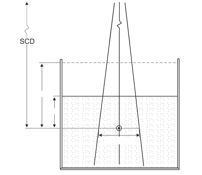
69
used in hospitals and standards laboratories. This is of importance because the beams
produced by the non-clinical accelerators found in some standards laboratories will in
general not be identical to those from clinical accelerators.
6.3.2. Measurement of beam quality
The experimental set-up for measuring TPR
20,10
is shown in Fig. 6. The refer-
ence conditions of measurements are given in Table 12.
Although the definition of TPR
20,10
is strictly made in terms of ratios of
absorbed dose, the use of ionization ratios provides an acceptable accuracy owing to
the slow variation with depth of water/air stopping-power ratios and the assumed con-
stancy of perturbation factors beyond the depth of dose maximum. The influence of
FIG. 6. Experimental set-up for the determination of the beam quality index Q (TPR
20,10
). The
source-to-chamber distance (SCD) is kept constant at 100 cm and measurements are made
with 10 g/cm
2
and 20 g/cm
2
of water over the chamber. The field size at the position of the
reference point of the chamber is 10 cm
×
10 cm. Either a cylindrical or a plane-parallel
ionization chamber can be used.
10 g/cm²
20 g/cm²
10 cm × 10 cm

70
recombination effects at the two depths should be investigated and taken into account
if there is a variation with depth.
6.4. DETERMINATION OF ABSORBED DOSE TO WATER
6.4.1. Reference conditions
The reference conditions for determination of absorbed dose to water are given
in Table 13.
6.4.2. Determination of absorbed dose under reference conditions
The general formalism is given in Section 3. The absorbed dose to water at the
reference depth z
ref
in water, in a photon beam of quality Q and in the absence of the
chamber, is given by
D
w,Q
= M
Q
N
D,w,Q
o
k
Q,Q
o
(20)
TABLE 12. REFERENCE CONDITIONS FOR THE DETERMINATION OF
PHOTON BEAM QUALITY (TPR
20,10
)
Influence quantity Reference value or reference characteristics
Phantom material Water
Chamber type Cylindrical or plane parallel
Measurement depths 20 g/cm
2
and 10 g/cm
2
Reference point of the chamber For cylindrical chambers, on the central axis at the
centre of the cavity volume. For plane-parallel
chambers, on the inner surface of the window at its
centre
Position of the reference For cylindrical and plane-parallel chambers, at the
point of the chamber measurement depths
SCD 100 cm
Field size at SCD 10 cm × 10 cm
a
a
The field size is defined at the plane of the reference point of the detector, placed at the
recommended depths in the water phantom.

71
where M
Q
is the reading of the dosimeter with the reference point of the chamber
positioned at z
ref
in accordance with the reference conditions given in Section 6.4.1
and corrected for the influence quantities temperature and pressure, electrometer
calibration, polarity effect and ion recombination as described in the worksheet (see
also Section 4.4.3). N
D,w,Q
o
is the calibration factor in terms of absorbed dose to water
for the dosimeter at the reference quality Q
o
, and k
Q,Q
o
is a chamber specific factor
which corrects for the difference between the reference beam quality Q
o
and the
actual quality being used, Q.
6.4.3. Absorbed dose at z
max
Section 6.4.2 provides a methodology for determining absorbed dose at z
ref
.
However, clinical dosimetry calculations are often referenced to the depth of dose
TABLE 13. REFERENCE CONDITIONS FOR THE DETERMINATION OF
ABSORBED DOSE TO WATER IN HIGH ENERGY PHOTON BEAMS
Influence quantity Reference value or reference characteristics
Phantom material Water
Chamber type Cylindrical
Measurement depth z
ref
For TPR
20,10
< 0.7, 10 g/cm
2
(or 5 g/cm
2
)
a
For TPR
20,10
≥ 0.7, 10 g/cm
2
Reference point of the chamber On the central axis at the centre of the cavity volume
Position of the reference point
of the chamber At the measurement depth z
ref
SSD/SCD 100 cm
b
Field size 10 cm × 10 cm
c
a
In an ESTRO–IAEA report on monitor unit calculations [77], the use of a single reference
depth z
ref
= 10 g/cm
2
for all photon beam energies is recommended. The constancy with
depth of N
D,w
reported by the BIPM [30] validates this option. However, some users may
prefer using the same reference depth as that used for
60
Co beams, i.e. z
ref
= 5 g/cm
2
; this
option is therefore allowed in this Code of Practice.
b
If the reference dose has to be determined for an isocentric set up, the SAD of the acceler-
ator shall be used even if this is not 100 cm.
c
The field size is defined at the surface of the phantom for a SSD type set-up, whereas for a
SAD type set-up it is defined at the plane of the detector, placed at the reference depth in the
water phantom at the isocentre of the machine.

72
TABLE 14. CALCULATED VALUES OF k
Q
FOR HIGH ENERGY PHOTON BEAMS FOR VARIOUS CYLINDRICAL
IONIZATION CHAMBERS AS A FUNCTION OF BEAM QUALITY TPR
20,10
(adapted from Andreo [20])
Beam quality TPR
20,10
Ionization chamber type
a
0.50 0.53 0.56 0.59 0.62 0.65 0.68 0.70 0.72 0.74 0.76 0.78 0.80 0.82 0.84
Capintec PR-05P mini 1.004 1.003 1.002 1.001 1.000 0.998 0.996 0.994 0.991 0.987 0.983 0.975 0.968 0.960 0.949
Capintec PR-05 mini 1.004 1.003 1.002 1.001 1.000 0.998 0.996 0.994 0.991 0.987 0.983 0.975 0.968 0.960 0.949
Capintec PR-06C/G 1.001 1.001 1.000 0.998 0.998 0.995 0.992 0.990 0.988 0.984 0.980 0.972 0.965 0.956 0.944
Farmer
Exradin A2 Spokas 1.001 1.001 1.001 1.000 0.999 0.997 0.996 0.994 0.992 0.989 0.986 0.979 0.971 0.962 0.949
Exradin T2 Spokas 1.002 1.001 0.999 0.996 0.993 0.988 0.984 0.980 0.977 0.973 0.969 0.962 0.954 0.946 0.934
Exradin A1 mini Shonka 1.002 1.002 1.001 1.000 1.000 0.998 0.996 0.994 0.991 0.986 0.982 0.974 0.966 0.957 0.945
Exradin T1 mini Shonka 1.003 1.001 0.999 0.996 0.993 0.988 0.984 0.980 0.975 0.970 0.965 0.957 0.949 0.942 0.930
Exradin A12 Farmer 1.001 1.001 1.000 1.000 0.999 0.997 0.994 0.992 0.990 0.986 0.981 0.974 0.966 0.957 0.944
Far West Tech. IC-18 1.005 1.003 1.000 0.997 0.993 0.988 0.983 0.979 0.976 0.971 0.966 0.959 0.953 0.945 0.934
FZH TK 01 1.002 1.001 1.000 0.998 0.996 0.993 0.990 0.987 0.984 0.980 0.975 0.968 0.960 0.952 0.939
Nuclear Assoc. 30-750 1.001 1.001 1.000 0.999 0.998 0.996 0.994 0.991 0.988 0.984 0.979 0.971 0.963 0.954 0.941
Nuclear Assoc. 30-749 1.001 1.000 1.000 0.999 0.998 0.996 0.994 0.992 0.989 0.984 0.980 0.972 0.964 0.956 0.942
Nuclear Assoc. 30-744 1.001 1.000 1.000 0.999 0.998 0.996 0.994 0.992 0.989 0.984 0.980 0.972 0.964 0.956 0.942
Nuclear Assoc. 30-716 1.001 1.000 1.000 0.999 0.998 0.996 0.994 0.992 0.989 0.984 0.980 0.972 0.964 0.956 0.942
Nuclear Assoc. 30-753 1.001 1.000 1.000 0.999 0.998 0.996 0.994 0.992 0.989 0.985 0.980 0.973 0.965 0.956 0.943
Farmer shortened
Nuclear Assoc. 30-751 1.002 1.002 1.000 0.999 0.997 0.994 0.991 0.989 0.985 0.981 0.977 0.969 0.961 0.953 0.940
Farmer
Nuclear Assoc. 30-752 1.004 1.003 1.001 1.000 0.998 0.996 0.993 0.991 0.989 0.985 0.981 0.974 0.967 0.959 0.947
Farmer
73
TABLE 14. (cont.)
NE 2515 1.001 1.001 1.000 0.999 0.997 0.994 0.991 0.988 0.984 0.980 0.975 0.967 0.959 0.950 0.937
NE 2515/3 1.005 1.004 1.002 1.000 0.998 0.995 0.993 0.991 0.989 0.986 0.982 0.975 0.969 0.961 0.949
NE 2577 1.005 1.004 1.002 1.000 0.998 0.995 0.993 0.991 0.989 0.986 0.982 0.975 0.969 0.961 0.949
NE 2505 Farmer 1.001 1.001 1.000 0.999 0.997 0.994 0.991 0.988 0.984 0.980 0.975 0.967 0.959 0.950 0.937
NE 2505/A Farmer 1.005 1.003 1.001 0.997 0.995 0.990 0.985 0.982 0.978 0.974 0.969 0.962 0.955 0.947 0.936
NE 2505/3, 3A Farmer 1.005 1.004 1.002 1.000 0.998 0.995 0.993 0.991 0.989 0.986 0.982 0.975 0.969 0.961 0.949
NE 2505/3, 3B Farmer 1.006 1.004 1.001 0.999 0.996 0.991 0.987 0.984 0.980 0.976 0.971 0.964 0.957 0.950 0.938
NE 2571 Farmer 1.005 1.004 1.002 1.000 0.998 0.995 0.993 0.991 0.989 0.986 0.982 0.975 0.969 0.961 0.949
NE 2581 Farmer 1.005 1.003 1.001 0.998 0.995 0.991 0.986 0.983 0.980 0.975 0.970 0.963 0.956 0.949 0.937
NE 2561/2611 Sec. Std 1.006 1.004 1.001 0.999 0.998 0.994 0.992 0.990 0.988 0.985 0.982 0.975 0.969 0.961 0.949
PTW 23323 micro 1.003 1.003 1.000 0.999 0.997 0.993 0.990 0.987 0.984 0.980 0.975 0.967 0.960 0.953 0.941
PTW 23331 rigid 1.004 1.003 1.000 0.999 0.997 0.993 0.990 0.988 0.985 0.982 0.978 0.971 0.964 0.956 0.945
PTW 23332 rigid 1.004 1.003 1.001 0.999 0.997 0.994 0.990 0.988 0.984 0.980 0.976 0.968 0.961 0.954 0.943
PTW 23333 1.004 1.003 1.001 0.999 0.997 0.994 0.990 0.988 0.985 0.981 0.976 0.969 0.963 0.955 0.943
PTW 30001/30010 Farmer 1.004 1.003 1.001 0.999 0.997 0.994 0.990 0.988 0.985 0.981 0.976 0.969 0.962 0.955 0.943
PTW 30002/30011 Farmer 1.006 1.004 1.001 0.999 0.997 0.994 0.992 0.990 0.987 0.984 0.980 0.973 0.967 0.959 0.948
PTW 30004/30012 Farmer 1.006 1.005 1.002 1.000 0.999 0.996 0.994 0.992 0.989 0.986 0.982 0.976 0.969 0.962 0.950
PTW 30006/30013 Farmer 1.002 1.002 1.000 0.999 0.997 0.994 0.990 0.988 0.984 0.980 0.975 0.968 0.960 0.952 0.940
PTW 31002 flexible 1.003 1.002 1.000 0.999 0.997 0.994 0.990 0.988 0.984 0.980 0.975 0.968 0.960 0.952 0.940
PTW 31003 flexible 1.003 1.002 1.000 0.999 0.997 0.994 0.990 0.988 0.984 0.980 0.975 0.968 0.960 0.952 0.940
SNC 100730 Farmer 1.004 1.003 1.001 0.999 0.997 0.993 0.990 0.988 0.985 0.981 0.977 0.970 0.963 0.956 0.944
SNC 100740 Farmer 1.006 1.005 1.002 1.000 0.999 0.996 0.994 0.992 0.990 0.987 0.983 0.977 0.971 0.963 0.951
Victoreen 1.005 1.004 1.001 0.998 0.996 0.993 0.989 0.986 0.983 0.979 0.975 0.968 0.961 0.954 0.943
Radocon III 550

74
TABLE 14. (cont.)
Victoreen 1.005 1.003 1.000 0.997 0.995 0.990 0.986 0.983 0.979 0.975 0.970 0.963 0.956 0.949 0.938
Radocon II 555
Victoreen 30-348 1.004 1.003 1.000 0.998 0.996 0.992 0.989 0.986 0.982 0.978 0.973 0.966 0.959 0.951 0.940
Victoreen 30-351 1.004 1.002 1.000 0.998 0.996 0.992 0.989 0.986 0.983 0.979 0.974 0.967 0.960 0.952 0.941
Victoreen 30-349 1.003 1.002 1.000 0.998 0.996 0.992 0.989 0.986 0.983 0.980 0.976 0.969 0.962 0.954 0.942
Victoreen 30-361 1.004 1.003 1.000 0.998 0.996 0.992 0.989 0.986 0.983 0.979 0.974 0.967 0.960 0.953 0.942
Scdx-Wellhöfer IC 05 1.001 1.000 1.000 0.999 0.998 0.996 0.994 0.992 0.989 0.984 0.980 0.972 0.964 0.956 0.942
Scdx-Wellhöfer IC 06 1.001 1.000 1.000 0.999 0.998 0.996 0.994 0.992 0.989 0.984 0.980 0.972 0.964 0.956 0.942
Scdx-Wellhöfer IC 10 1.001 1.000 1.000 0.999 0.998 0.996 0.994 0.992 0.989 0.984 0.980 0.972 0.964 0.956 0.942
Scdx-Wellhöfer IC 15 1.001 1.000 1.000 0.999 0.998 0.996 0.994 0.992 0.989 0.984 0.980 0.972 0.964 0.956 0.942
Scdx-Wellhöfer IC 25 1.001 1.000 1.000 0.999 0.998 0.996 0.994 0.992 0.989 0.984 0.980 0.972 0.964 0.956 0.942
Scdx-Wellhöfer IC 28 1.001 1.000 1.000 0.999 0.998 0.996 0.994 0.992 0.989 0.985 0.980 0.973 0.965 0.956 0.943
Farmer shortened
Scdx-Wellhöfer
IC 69 Farmer 1.002 1.002 1.000 0.999 0.997 0.994 0.991 0.989 0.985 0.981 0.977 0.969 0.961 0.953 0.940
Scdx-Wellhöfer
IC 70 Farmer 1.004 1.003 1.001 1.000 0.998 0.996 0.993 0.991 0.988 0.985 0.981 0.974 0.967 0.959 0.946
a
Some of the chambers listed in this table fail to meet some of the minimum requirements described in Section 4.2.1. However, they have been included
because of their current clinical use.
75
maximum z
max
(or at some other depth). To determine the absorbed dose at the appro-
priate depth the user should, for a given beam, use the central axis PDD data for SSD
set-ups and TPR or TMRs for SAD set-ups. Section 6.7.1 describes how to generate
central axis PDD data.
6.5. VALUES FOR k
Q,Q
o
6.5.1. Chamber calibrated in
60
Co
When the reference quality Q
o
is
60
Co, k
Q,Q
o
is denoted by k
Q
and N
D,w,Q
o
is
denoted by N
D,w
.
Calculated values for the factor k
Q
are given in Table 14 for a series of user
qualities Q (i.e. TPR
20,10
) and for a number of chamber types. These values have
been adapted from the calculations of Andreo [20] and can be used at the reference
depths given in Table 13. A sleeve of 0.5 mm thick PMMA has been used in the
calculations for all the chambers which are not waterproof; for sleeve thicknesses
up to 1 mm the change in k
Q
is not greater than about 0.1%. Values of k
Q
for non-
tabulated qualities may be obtained by interpolation. For illustrative purposes a plot
of calculated k
Q
values for selected chamber types in common use is given in Fig. 7.
The stopping-power ratios and perturbation factors used to calculate k
Q
are
described in Appendix II. It is emphasized that calculated k
Q
values cannot distin-
guish chamber to chamber variations within a given chamber type and their use
necessarily involves larger uncertainties than directly measured values (see
Section 6.8).
It should be noted that there is no value of Q that corresponds to
60
Co where all
the k
Q
values are equal to 1.000. While in principle there is a value of TPR
20,10
that
would correspond to a pure
60
Co spectrum, the response of a particular chamber in an
accelerator beam of the same TPR
20,10
depends on its energy response over the whole
spectrum, and will not necessarily be the same as for
60
Co. In addition there is
considerable disagreement in the literature as to what the TPR
20,10
of a
60
Co beam is
(0.568 for the beam in Ref. [86]; 0.572 in Refs [81, 87, 88]; 0.578 in Ref. [89];
0.579 in Ref. [90], etc.), so that a single reference value cannot be used.
6.5.2. Chamber calibrated in a series of photon beam qualities
For a chamber calibrated in a series of photon beam qualities, the data from the
calibration laboratory will ideally be presented in the form of a single calibration
factor N
D,w,Q
o
and a set of measured factors k
Q,Q
o
. From the latter, a value for k
Q,Q
o
at the user quality Q may be derived by interpolation. N
D,w,Q
o
and the resulting k
Q,Q
o
are then used directly in Eq. (20).

76
When the calibration laboratory provides a series of calibration factors N
D,w,Q
,
data must first be converted to the above format by choosing one of the photon beam
qualities used by the calibration laboratory as reference quality Q
o
. The k
Q,Q
o
factors
are evaluated using
(21)
Interpolation to determine k
Q,Q
o
at the user quality Q then proceeds as above. Note
that when the reference quality Q
o
is
60
Co, k
Q,Q
o
is denoted by k
Q
and N
D,w,Q
o
is
denoted by N
D,w
.
Once experimental values for N
D,w,Q
o
and k
Q,Q
o
are obtained for a particular
chamber, it may not be necessary for the user to calibrate the chamber every time at
all qualities Q, but only at the single reference quality Q
o
. In this case the new
calibration factor N
D,w,Q
o
should be used in conjunction with the existing values for
D,w,Q
Q,Q
o
D,w,Q
o
N
k=
N
FIG. 7. Sigmoidal fits of calculated values of k
Q
for various cylindrical ionization chambers
commonly used for reference dosimetry, as a function of photon beam quality, Q (TPR
20,10
).
Open symbols correspond to graphite walled ionization chambers, solid symbols to plastic
walled chambers. Data from Table 14.
Photon beam quality, Q (TPR
20,10
)
0.50 0.55 0.60 0.65 0.70 0.75 0.80 0.85
k
Q
0.93
0.94
0.95
0.96
0.97
0.98
0.99
1.00
1.01

77
k
Q,Q
o
and the quality dependence of that chamber (k
Q,Q
o
values) needs to be verified
every third calibration cycle of the chamber or if the user suspects that the chamber
has been damaged. The single calibration does not need to be performed at the same
laboratory where the experimental k
Q,Q
o
values were measured. Note, however, that
this procedure should not be repeated more than twice in succession; the chamber
should be recalibrated at all qualities at least every six years.
6.5.3. Chamber calibrated at Q
o
with generic experimental k
Q,Q
o
values
Calibration laboratories sometimes provide generic experimental k
Q,Q
o
values
measured for a particular chamber type, together with a single experimental N
D,w,Q
o
for
the user chamber where the reference quality Q
o
is usually
60
Co. Only those generic
values of k
Q,Q
o
that have been obtained by a standards laboratory from a large sample
of ionization chambers and whose standard deviation of chamber to chamber differ-
ences is small are recommended for use in this Code of Practice (see Section 4.1).
Generic values not determined by a standards laboratory are not recommended.
It is emphasized that directly measured values of k
Q,Q
o
for an individual
chamber within a given chamber type are the preferred choice in this Code of
Practice, followed by the calculated values of k
Q,Q
o
for a given chamber type given in
Table 14. Note that if generic values for k
Q,Q
o
(measured for a particular chamber
type) exist, these should be used only if they meet the criteria expressed in
Section 4.1.
6.6. CROSS-CALIBRATION OF FIELD IONIZATION CHAMBERS
As noted in Section 6.2.1, a field chamber may be cross-calibrated against a
calibrated reference chamber at the reference quality Q
o
. The chambers are compared
by alternately placing the chambers in a water phantom with their reference points at
z
ref
(a side by side chamber intercomparison is a possible alternate configuration).
The calibration factor in terms of absorbed dose to water for the field ionization
chamber is given by
(22)
where M
ref
and M
field
are the meter readings per monitor unit (MU) for the reference
and field chambers, respectively, corrected for the influence quantities temperature and
pressure, electrometer calibration, polarity effect and ion recombination as described
in the worksheet (see also Section 4.4.3) and N
ref
D,w,Q
o
is the calibration factor in terms
field ref
ref
field
D,w,Q D,w,Q
oo
M
N=N
M

of absorbed dose to water for the reference chamber. Preferably, the readings M
ref
and
M
field
should actually be the averages and , where (M
ref
/M
em
)
i
and (M
field
/M
em
)
i
are, respectively, the ratios of the reading of the reference detector
and the field instrument to the reading of an external monitor. The external monitor
should preferably be positioned inside the phantom approximately at the depth z
ref
but
at a distance of 3–4 cm away from the chamber centre along the major axis in the
transverse plane of the beam. Note that in the case of a side by side measurement an
external monitor is not needed provided that the beam profile is adequately uniform.
The field chamber with the calibration factor N
field
D,w,Q
o
may be used subsequently
for the determination of absorbed dose to water in the user beam using the procedure
of Section 6.4.2, where N
D,w,Q
o
is replaced by N
field
D,w,Q
o
.
6.7. MEASUREMENTS UNDER NON-REFERENCE CONDITIONS
Clinical dosimetry requires the measurements of PDD, TPRs or TMRs, isodose
distributions, transverse beam profiles and output factors as a function of field size
and shape for both reference and non-reference conditions. Such measurements
should be made for all possible combinations of energy, field size and SSD or SAD
used for radiotherapy treatment.
6.7.1. Central axis depth dose distributions
All measurements should follow the recommendations given in Section 4.2
regarding choices for phantoms and dosimeters, although other types of detectors can
also be used. For measurements of depth ionization curves, plane-parallel ionization
chambers are recommended. If a cylindrical ionization chamber is used instead, then the
effective point of measurement of the chamber must be taken into account. This requires
that the complete depth ionization distribution be shifted towards the surface a distance
equal to 0.6 r
cyl
[17, 21] where r
cyl
is the cavity radius of the cylindrical ionization
chamber. To make accurate measurements in the buildup region, extrapolation cham-
bers or well guarded fixed separation plane-parallel chambers should be used. Attention
should be paid to the use of certain solid state detectors (some types of diodes and dia-
mond detectors) to measure depth dose distributions (see, for instance, Ref. [21]); only
a solid state detector whose response has been regularly verified against a reference
detector (ionization chamber) should be selected for these measurements.
Since the stopping power ratios and perturbation effects can be assumed to a
reasonable accuracy to be independent of depth for a given beam quality and field
size, relative ionization distributions can be used as relative distributions of absorbed
dose, at least for depths at and beyond the depth of dose maximum.
field em
M/M
ref em
M/M
78

6.7.2. Output factors
The output factor may be determined as the ratio of corrected dosimeter read-
ings measured under a given set of non-reference conditions to that measured under
reference conditions. These measurements are typically done at the depth of max-
imum dose or at the reference depth [77] and corrected to the depth of maximum dose
using PDD (or TMR). When output factors are measured in open as well as wedged
beams, special attention should be given to the uniformity of the radiation fluence
over the chamber cavity. This is especially important for field sizes smaller than
5cm× 5 cm. Some accelerators have very pronounced V shaped photon beam pro-
files which usually vary with depth and field size. For large detectors it may be diffi-
cult to correct for this variation accurately. Thimble chambers with large cavity length
and plane-parallel chambers with large collecting electrodes (see Section 4.2.1 for
chamber requirements) should therefore be avoided in situations where the beams
have pronounced V shaped profiles.
In wedged photon beams the radiation intensity varies strongly in the direction
of the wedge. For output measurements in such beams the detector dimension in the
wedge direction should be as small as possible. A small thimble chamber aligned with
its axis perpendicular to the wedge direction is recommended. The coincidence of the
central axes of the beam, the collimator and the wedge should be ensured prior to
making the output measurements.
6.8. ESTIMATED UNCERTAINTY IN THE DETERMINATION
OF ABSORBED DOSE TO WATER UNDER REFERENCE CONDITIONS
When a reference dosimeter is used for the determination of absorbed dose to
water in the user beam, the uncertainties in the different physical quantities or proce-
dures that contribute to the dose determination can be divided into two steps. Step 1
considers uncertainties up to the calibration of the user reference dosimeter in terms
of N
D,w
at the standards laboratory. Step 2 deals with the calibration of the user beam
and includes the uncertainties associated with the measurements at the reference point
in a water phantom. Step 2 also includes the uncertainty of the k
Q
value. The uncer-
tainties of the factors that contribute to the uncertainty of calculated k
Q
values can be
found in Appendix II. Combining the uncertainties in quadrature in the various steps
yields the combined standard uncertainty for the determination of the absorbed dose
to water at the reference point.
An estimate of the uncertainties in the calibration of a high energy photon beam
is given in Table 15. When the calibration of the reference dosimeter is carried out in
the
60
Co beam of an SSDL, the combined standard uncertainty in D
w
is estimated to
be typically about 1.5%, based on calculated values of k
Q
. This estimate may vary
79

80
depending on the uncertainty quoted by the calibration laboratory. If the calibration
of the reference dosimeter is carried out at a PSDL, but calculated values of k
Q
are
used, the final uncertainty in D
w
is not expected to decrease as it is dominated by the
uncertainty in the k
Q
values. If these values are measured at the PSDL for the user
chamber, the uncertainty in D
w
decreases to about 1.2%. If a field dosimeter is used,
the uncertainty in dose determination increases somewhat (by approximately 0.2%)
because of the additional step needed to cross-calibrate the field dosimeter against the
calibrated reference dosimeter.
TABLE 15. ESTIMATED RELATIVE STANDARD UNCERTAINTY
a
OF D
w,Q
AT
THE REFERENCE DEPTH IN WATER AND FOR A HIGH ENERGY PHOTON
BEAM, BASED ON A CHAMBER CALIBRATION IN
60
Co GAMMA
RADIATION
Physical quantity or procedure Relative standard uncertainty (%)
Step 1: Standards laboratory
b
N
D,w
calibration of secondary standard at PSDL 0.5
Long term stability of secondary standard 0.1
N
D,w
calibration of the user dosimeter at the standard laboratory 0.4
Combined uncertainty of step 1 0.6
Step 2: User high energy photon beam
Long term stability of user dosimeter 0.3
Establishment of reference conditions 0.4
Dosimeter reading M
Q
relative to beam monitor 0.6
Correction for influence quantities k
i
0.4
Beam quality correction k
Q
(calculated values) 1.0
c
Combined uncertainty of step 2 1.4
Combined standard uncertainty of D
w,Q
(steps 1 + 2) 1.5
a
See the ISO Guide for the expression of uncertainty [32], or Appendix IV. The estimates given
in the table should be considered typical values; these may vary depending on the uncertainty
quoted by standards laboratories for calibration factors and on the experimental uncertainty
at the user’s institution.
b
If the calibration of the user dosimeter is performed at a PSDL, then the combined standard
uncertainty in step 1 is lower. The combined standard uncertainty in D
w
should be adjusted
accordingly.
c
If k
Q
is measured at a PSDL for the user chamber, this uncertainty is approximately of the
order of 0.7%.

81
6.9. WORKSHEET
Determination of the absorbed dose to water in a high energy photon beam
User: ____________________________________________________ Date: _______________
1. Radiation treatment unit and reference conditions for D
w,Q
determination
Accelerator: Nominal Acc. potential: MV
Nominal dose rate:
MU/min Beam quality, Q (TPR
20,10
):
Reference phantom: water Set-up: ❏ SSD ❏ SAD
Reference field size: cm × cm Reference distance (cm):
Reference depth z
ref
: ___________ g/cm
2
2. Ionization chamber and electrometer
Ionization chamber model: ________________ Serial No.: ____________
Chamber wall material: thickness: g/cm
2
Waterproof sleeve material: thickness: g/cm
2
Phantom window material: thickness: g/cm
2
Absorbed dose to water calibration factor
a
N
D,w,Q
o
= _________________ ❏ Gy/nC ❏ Gy/rdg
Calibration quality Q
o
❏
60
Co ❏ photon beam Calibration depth: ____________ g/cm
2
If Q
o
is photon beam, give TPR
20,10
: _____________
Reference conditions for calibration P
o
: _________ kPa T
o
: ________ °C Rel. humidity: ___ %
Polarizing potential V
l
:__________ V Calibration polarity: ❏ +ve ❏ –ve ❏ corrected for polarity
User polarity: ❏ +ve ❏ –ve
effect
Calibration laboratory: Date:
Electrometer model: Serial No.:
Calibrated separately from chamber: ❏ yes ❏ no Range setting:
If yes, calibration laboratory:
Date:
3. Dosimeter reading
b
and correction for influence quantities
Uncorrected dosimeter reading at V
1
and user polarity: ❏ nC ❏ rdg
Corresponding accelerator monitor units: MU
Ratio of dosimeter reading and monitor units: M
1
= ❏ nC/MU ❏ rdg/MU
(i) Pressure P: ______ kPa Temperature T: ________ °C Rel. humidity (if known): ______ %
(ii) Electrometer calibration factor
c
k
elec
: ❏ nC/rdg ❏ dimensionless k
elec
=
(iii) Polarity correction
d
rdg at + V
1
: M
+
= ________ rdg at –V
1
: M
_
=
= _________________
k
MM
M
pol
=
+
+-
2
k
T
T
P
P
TP
o
o
=
+
+
=
(. )
(. )
273 2
273 2
10 × 10

82
(iv) Recombination correction (two voltage method)
Polarizing voltages: V
1
(normal) = __________ V V
2
(reduced) = ______________ V
Readings
e
at each V: M
1
= _________________ M
2
= ______________________
Voltage ratio V
1
/V
2
= ___________ Ratio of readings M
1
/M
2
= ___________
Use Table 9 for a beam of type: ❏ pulsed ❏ pulsed–scanned
a
0
= ____________ a
1
= ____________ a
2
= ____________
________________
Corrected dosimeter reading at the voltage V
1
:
M
Q
= M
1
k
TP
k
elec
k
pol
k
s
= ____________ ❏ nC/MU ❏ rdg/MU
4. Absorbed dose to water at the reference depth z
ref
Beam quality correction factor for the user quality Q: k
Q,Q
o
=
taken from ❏ Table 14 ❏ Other, specify:
D
w,Q
(z
ref
) = M
Q
N
D,w,Q
o
k
Q,Q
o
= Gy/MU
5. Absorbed dose to water at the depth of dose maximum z
max
Depth of dose maximum: z
max
= ______________________ g/cm
2
(i) SSD set-up
Percentage depth dose at z
ref
for a 10 cm × 10 cm field size: PDD (z
ref
= _______ g/cm
2
) = _____ %
Absorbed dose calibration of monitor at z
max
:
D
w,Q
(z
max
) = 100 D
w,Q
(z
ref
)/PDD (z
ref
) = ___________________ Gy/MU
(ii) SAD set-up
TMR at z
ref
for a 10 cm × 10 cm field size: TMR (z
ref
= _______________ g/cm
2
) = ____________
Absorbed dose calibration of monitor at z
max
:
D
w,Q
(z
max
) = D
w,Q
(z
ref
)/TMR(z
ref
) = __________________ Gy/MU
a
Note that if Q
o
is
60
Co, N
D,w,Q
o
is denoted by N
D,w
.
b
All readings should be checked for leakage and corrected if necessary.
c
If the electrometer is not calibrated separately, set k
elec
= 1.
d
M in the denominator of k
pol
denotes reading at the user polarity. Preferably, each reading in the equation
should be the average of the ratios of M (or M
+
or M
–
) to the reading of an external monitor, M
em
.
It is assumed that the calibration laboratory has performed a polarity correction. Otherwise k
pol
is
determined according to:
rdg at +V
1
for quality Q
o
: M
+
= ________ rdg at –V
1
for quality Q
o
: M
–
= ________
_______________________
e
Strictly, readings should be corrected for polarity effect (average with both polarities). Preferably, each
reading in the equation should be the average of the ratios of M
1
or M
2
to the reading of an external
monitor, M
em
.
()
()
pol
+–
Q
+–
Q
o
M+M M
k= =
M+M M
È˘
Î˚
È˘
Î˚
kaa
M
M
a
M
M
s
=+
Ê
Ë
Á
ˆ
¯
˜
+
Ê
Ë
Á
ˆ
¯
˜
=
01
1
2
2
1
2
2

83
f
It is assumed that the calibration laboratory has performed a recombination correction. Otherwise the
factor k
′
s
= k
s
/k
s,Q
o
should be used instead of k
s
. When Q
o
is
60
Co, k
s,Q
o
(at the calibration laboratory) will
normally be close to unity and the effect of not using this equation will be negligible in most cases.
g
Check that
h
Note that if Q
o
is
60
Co, k
Q
, Q
o
is denoted by k
Q
, as given in Table 14.
12
12
1
1
1
s
MM–
k–
VV–
ª

84
7. CODE OF PRACTICE FOR
HIGH ENERGY ELECTRON BEAMS
7.1. GENERAL
This section provides a Code of Practice for reference dosimetry (beam
calibration) and recommendations for relative dosimetry in clinical electron beams
with energies in the range from 3–50 MeV. It is based upon a calibration factor in
terms of absorbed dose to water N
D,w,Q
o
for a dosimeter in a reference beam of quality
Q
o
. This reference quality may be either
60
Co gamma radiation or an electron beam
quality. In the latter case the dosimeter may be calibrated either directly at a standards
laboratory or by cross-calibration in a clinical electron beam.
Aside from having its foundation on standards of absorbed dose, the most
significant change from current practice is the use of a new reference depth. This
depth has been shown to reduce significantly the influence of spectral differences
between different accelerators as well as that of electron and photon contamination in
clinical electron beams [21, 91]. For simplicity, beam qualities and all factors depen-
dent on beam quality (including the new reference depth) are expressed in terms of
the half-value depth R
50
rather than beam energy. This change parallels the long
standing practice in photon dosimetry, where beam qualities are expressed in terms
of the penetration of the beam.
7.2. DOSIMETRY EQUIPMENT
7.2.1. Ionization chambers
The recommendations regarding ionization chambers given in Section 4.2.1
should be followed. Plane-parallel chambers are the recommended type for all beam
qualities and must be used for beam qualities R
50
< 4 g/cm
2
(E
o
10 MeV).
26
Ideally,
the chamber should be calibrated in an electron beam, either directly at a standards
laboratory or by cross-calibration in a clinical electron beam. The reference point for
plane-parallel chambers is taken to be on the inner surface of the entrance window, at
26
The approximate relation E
o
= 2.33 R
50
is assumed, where E
o
is the mean energy at
the phantom surface in MeV and R
50
is expressed in g/cm
2
. The value stated for R
50
takes
precedence over that stated for E
o
.

85
the centre of the window. This point should be positioned at the point of interest in
the phantom. Chamber window thicknesses (in mm and in mg/cm
2
) for a variety of
plane-parallel chamber types are given in Table 4.
For beam qualities R
50
≥ 4 g/cm
2
(E
o
10 MeV) cylindrical chambers may be
used. The reference point for cylindrical chambers is taken to be on the chamber axis
at the centre of the cavity volume. For measurements in electron beams this reference
point should be positioned a distance 0.5 r
cyl
deeper than the point of interest in the
phantom, where r
cyl
is the radius of the air cavity.
27
Values for r
cyl
for a variety of
cylindrical chamber types are given in Table 3.
7.2.2. Phantoms and chamber sleeves
The recommendations regarding phantoms and chamber sleeves given in
Sections 4.2.3 and 4.2.4 should be followed, both for determination of absorbed dose
and for beam quality specification. Water is recommended as the reference medium
for measurements in electron beams. The water phantom should extend to at least
5 cm beyond all four sides of the largest field size employed at the depth of mea-
surement. There should also be a margin of at least 5 g/cm
2
beyond the maximum
depth of measurement.
In a horizontal electron beam, the window of the phantom should be of plastic
and of thickness t
win
between 0.2 cm and 0.5 cm.
28
The water equivalent thickness of
the phantom window (in g/cm
2
) should be taken into account when positioning the
chamber at the desired measurement depth. This thickness is calculated as the product
t
win
ρ
pl
, where
ρ
pl
is the density of the plastic (in g/cm
3
). For the commonly used
plastics PMMA and clear polystyrene, the nominal values
ρ
PMMA
= 1.19 g/cm
3
and
ρ
polystyrene
= 1.06 g/cm
3
may be used [64].
Under certain circumstances and for beam qualities R
50
< 4 g/cm
2
(E
o
10 MeV), a plastic phantom may be used; all depths must then be appropriately scaled
(see Sections 4.2.3 and 7.8).
29
27
As with the concept of ‘effective point of measurement’(see Section 1.6), positioning
the chamber in this way is used to avoid the need for a fluence gradient correction. This is of
particular significance because, in common with Refs [17, 21], the reference depth as defined
in this Code of Practice does not always coincide with that of the dose maximum.
28
A window of only a few millimetres in thickness may bow outwards slightly owing to
water pressure on the inner surface. Any such effect should be accounted for when positioning
the chamber at the depth of interest, particularly in low energy electron beams.
29
Plastic phantoms can be used for routine quality assurance measurements, provided a
transfer factor between plastic and water has been established at the time of beam calibration.
86
Plane-parallel chambers, if not inherently waterproof or supplied with a water-
proof cover, should be used in a waterproof enclosure, preferably of PMMA or a
material that matches the chamber walls. Ideally, there should be no more than 1 mm
of added material in front of and behind the air cavity. Cylindrical chambers should
be used in a PMMA sleeve, preferably not thicker than 1.0 mm. The air gap between
the chamber wall and the sleeve should be sufficient (0.1–0.3 mm) to allow the air
pressure in the chamber to follow the ambient air pressure. For both chamber types,
the same (or similar) waterproofing should be used for the determination of absorbed
dose to water at the user facility as was used for calibration at the standards
laboratory.
Strictly, when used in conjunction with the calculated values for k
Q,Q
o
given in
this section, the water equivalent thickness (in g/cm
2
) of the chamber wall and any
waterproofing material should be taken into account when positioning the chamber at
the point of interest. However, this is a very small effect and may be ignored in
practice. For general comments on the positioning of chambers, see Section 4.2.5.
7.3. BEAM QUALITY SPECIFICATION
7.3.1. Choice of beam quality index
For electron beams the beam quality index is the half-value depth in water R
50
.
This is the depth in water (in g/cm
2
) at which the absorbed dose is 50% of its value
at the absorbed dose maximum, measured with a constant SSD of 100 cm and a field
size at the phantom surface of at least 10 cm × 10 cm for R
50
≤ 7 g/cm
2
(E
o
16 MeV)
and at least 20 cm × 20 cm for R
50
> 7 g/cm
2
(E
o
16 MeV). As noted in Ref. [21],
some accelerators at high electron energies have an intrinsic poor homogeneity at
large field sizes, which may improve at smaller field sizes as a result of electrons
scattered from the collimator (or applicator, cones, etc.). In such cases a field size
smaller than 20 cm × 20 cm may be used provided that R
50
does not change by more
than around 0.1 g/cm
2
from the value measured for a 20 cm × 20 cm field.
The choice of R
50
as the beam quality index is a change from the current
practice of specifying beam quality in terms of the mean energy at the phantom
surface E
o
. As E
o
is normally derived from R
50
, this change in beam quality index is
merely a simplification which avoids the need for a conversion to energy.
7.3.2. Measurement of beam quality
The reference conditions for the determination of R
50
are given in Table 16. For
all beam qualities, the preferred choice of detector for the measurement of R
50
is a

87
plane-parallel chamber. For beam qualities R
50
≥ 4 g/cm
2
(E
o
10 MeV), a cylin-
drical chamber may be used, with the reference point positioned 0.5 r
cyl
deeper than
the point of interest in the phantom. A water phantom is the preferred choice. In a
vertical beam the direction of scan should be towards the surface to reduce the effect
of meniscus formation. For beam qualities R
50
< 4 g/cm
2
(E
o
10 MeV), a plastic
phantom may be used, in which case all depths must be scaled according to the
procedure described in Section 7.8.
Ion recombination and polarity corrections are required at all depths (see
Section 4.4.3). These may be derived from a reduced set of representative measure-
ments, for example near the surface, the ionization maximum and the depths
corresponding to 90% and 50% of the ionization maximum. For measurements made
over a short period of time, air temperature and pressure corrections need not be
made.
TABLE 16. REFERENCE CONDITIONS FOR THE DETERMINATION OF
ELECTRON BEAM QUALITY (R
50
)
Influence quantity Reference value or reference characteristics
Phantom material For R
50
≥ 4 g/cm
2
, water
For R
50
< 4 g/cm
2
, water or plastic
Chamber type For R
50
≥ 4 g/cm
2
, plane parallel or cylindrical
For R
50
< 4 g/cm
2
, plane parallel
Reference point of For plane parallel chambers, on the inner surface of the
the chamber window at its centre.
For cylindrical chambers, on the central axis at the centre of
the cavity volume
Position of the reference For plane-parallel chambers, at the point of interest
point of the chamber For cylindrical chambers, 0.5 r
cyl
deeper than the point of
interest
SSD 100 cm
Field size at phantom surface For R
50
≤ 7 g/cm
2
, at least 10 cm × 10 cm
For R
50
> 7 g/cm
2
, at least 20 cm × 20 cm
a
a
A field size smaller than 20 cm × 20 cm may be used provided that R
50
does not change by
more than around 0.1 g/cm
2
from the value measured for a 20 cm × 20 cm field.
When using an ionization chamber, the measured quantity is the half-value of
the depth ionization distribution in water, R
50,ion
. This is the depth in water (in g/cm
2
)
at which the ionization current is 50% of its maximum value. The half-value of the
depth dose distribution in water R
50
is obtained using [92]:
R
50
= 1.029 R
50,ion
– 0.06 g/cm
2
(R
50,ion
≤ 10 g/cm
2
)
(23)
R
50
= 1.059 R
50,ion
– 0.37 g/cm
2
(R
50,ion
> 10 g/cm
2
)
As an alternative to the use of an ionization chamber, other detectors (for
example diode, diamond, etc.) may be used to determine R
50
. In this case the user
must verify that the detector is suitable for depth dose measurements by test compar-
isons with an ionization chamber at a set of representative beam qualities.
7.4. DETERMINATION OF ABSORBED DOSE TO WATER
7.4.1. Reference conditions
The reference conditions for determination of absorbed dose to water in
electron beams are given in Table 17. Because the precise choice of field size is not
critical [21], a convenient choice for the reference field size is that which is used
for the normalization of output factors, subject to the constraint that it should not
be less than 10 cm × 10 cm at the phantom surface. The reference depth z
ref
is given
by [91]
z
ref
= 0.6 R
50
– 0.1 g/cm
2
(R
50
in g/cm
2
) (24)
This depth is close to the depth of the absorbed dose maximum z
max
at beam
qualities R
50
< 4 g/cm
2
(E
o
10 MeV), but at higher beam qualities is deeper than
z
max
. It is recognized that this choice of reference depth may be less convenient than
that recommended in Ref. [17], since for a given accelerator no two reference beams
will have the same reference depth. However, the new depth has been shown signif-
icantly to reduce machine to machine variations in chamber calibration factors [91]
and the accuracy gained justifies its use, particularly for plane-parallel chamber
types.
It should be noted that by recommending that reference dosimetry at higher
energies be conducted at a depth beyond z
max
, the uncertainty arising from cavity
perturbation effects for cylindrical chambers may be larger. In the worst case,
around R
50
= 5 g/cm
2
(E
o
around 12 MeV) the increased uncertainty is approxi-
mately 0.3%.
88

7.4.2. Determination of absorbed dose under reference conditions
The general formalism is given in Section 3. The absorbed dose to water at the
reference depth z
ref
in water, in an electron beam of quality Q and in the absence of
the chamber, is given by
D
w,Q
= M
Q
N
D,w,Q
o
k
Q,Q
o
(25)
where M
Q
is the reading of the dosimeter corrected for the influence quantities tem-
perature and pressure, electrometer calibration, polarity effect and ion recombination
as described in the worksheet (see also Section 4.4.3). The chamber should be
positioned in accordance with the reference conditions, as given in Table 17. N
D,w,Q
o
is the calibration factor in terms of absorbed dose to water for the dosimeter at the
reference quality Q
o
and k
Q,Q
o
is a chamber specific factor which corrects for
differences between the reference beam quality Q
o
and the actual beam quality Q.
89
TABLE 17. REFERENCE CONDITIONS FOR THE DETERMINATION OF
ABSORBED DOSE IN ELECTRON BEAMS
Influence quantity Reference value or reference characteristic
Phantom material For R
50
≥ 4 g/cm
2
, water
For R
50
< 4 g/cm
2
, water or plastic
Chamber type For R
50
≥ 4 g/cm
2
, plane parallel or cylindrical
For R
50
< 4 g/cm
2
, plane parallel
Measurement depth z
ref
0.6 R
50
– 0.1 g/cm
2
Reference point of the chamber For plane-parallel chambers, on the inner surface of the
window at its centre
For cylindrical chambers, on the central axis at the centre of
the cavity volume
Position of the reference For plane-parallel chambers, at z
ref
point of the chamber For cylindrical chambers, 0.5r
cyl
deeper than z
ref
SSD 100 cm
Field size at phantom surface 10 cm × 10 cm or that used for normalization of output
factors, whichever is larger

90
7.4.3. Absorbed dose at z
max
Clinical normalization most often takes place at the depth of the dose maximum
z
max
which, in this Code of Practice, does not always coincide with z
ref
. To determine
the absorbed dose at z
max
the user should, for a given beam, use the measured central
axis depth dose distribution to convert the absorbed dose at z
ref
to that at z
max
. The
measurement of depth dose distributions is discussed in Section 7.7.1.
7.5. VALUES FOR k
Q,Q
o
The general formalism is given in Section 3. The modified treatment of k
Q,Q
o
for chambers cross-calibrated in a user electron beam, as described in Section 3.2.1,
is dealt with in Section 7.6, which may also be applied to chambers calibrated directly
at a standards laboratory at a single electron beam quality. The stopping-power ratios
and perturbation factors used in the calculation of k
Q,Q
o
are described in Appendix II.
7.5.1. Chamber calibrated in
60
Co
When the reference quality Q
O
is
60
Co, the factor k
Q,Q
o
is denoted by k
Q
.
Calculated values for k
Q
are given in Table 18 for a series of user qualities Q and for
a number of chamber types; values for non-tabulated qualities may be obtained by
interpolation. These data are also presented in Figs 8 and 9 for plane-parallel and
cylindrical chamber types, respectively. Note that if generic values for k
Q,Q
o
(measured for a particular chamber type) exist, these should be used only if they meet
the criteria expressed in Section 4.1.
7.5.2. Chamber calibrated at a series of electron beam qualities
For a chamber calibrated at a series of electron beam qualities, the data from
the calibration laboratory will ideally be presented as a single calibration factor
N
D,w,Q
o
determined in a reference electron beam of quality Q
o
and one or more
measured factors k
Q,Q
o
corresponding to the other calibration qualities Q.
However, if the calibration data are in the form of a set of calibration factors
N
D,w,Q,
, then one of the calibration qualities
30
should be chosen as the reference
calibration quality Q
o
. The corresponding calibration factor is denoted N
D,w,Q
o
and the
30
The choice here is not critical; the quality corresponding to the N
D,w,Q
factor with the
smallest relative uncertainty is appropriate, otherwise a quality close to the middle of the range.

TABLE 18. CALCULATED VALUES FOR k
Q
FOR ELECTRON BEAMS, FOR VARIOUS CHAMBER TYPES CALIBRATED IN
60
Co GAMMA RADIATION, AS A FUNCTION OF BEAM QUALITY R
50
(the data are derived using values for stopping-power ratios and perturbation factors, as given in Appendix II)
Ionization
Beam quality R
50
(g/cm
2
)
chamber type
a
1.0 1.4 2.0 2.5 3.0 3.5 4.0 4.5 5.0 5.5 6.0 7.0 8.0 10.0 13.0 16.0 20.0
Plane-parallel chambers
Attix RMI 449 0.953 0.943 0.932 0.925 0.919 0.913 0.908 0.904 0.900 0.896 0.893 0.886 0.881 0.871 0.859 0.849 0.837
Capintec PS-033 — — 0.921 0.920 0.919 0.918 0.917 0.916 0.915 0.913 0.912 0.908 0.905 0.898 0.887 0.877 0.866
Exradin P11 0.958 0.948 0.937 0.930 0.923 0.918 0.913 0.908 0.904 0.901 0.897 0.891 0.885 0.875 0.863 0.853 0.841
Holt (Memorial) 0.971 0.961 0.950 0.942 0.936 0.931 0.926 0.921 0.917 0.913 0.910 0.903 0.897 0.887 0.875 0.865 0.853
NACP / Calcam 0.952 0.942 0.931 0.924 0.918 0.912 0.908 0.903 0.899 0.895 0.892 0.886 0.880 0.870 0.858 0.848 0.836
Markus — — 0.925 0.920 0.916 0.913 0.910 0.907 0.904 0.901 0.899 0.894 0.889 0.881 0.870 0.860 0.849
Roos 0.965 0.955 0.944 0.937 0.931 0.925 0.920 0.916 0.912 0.908 0.904 0.898 0.892 0.882 0.870 0.860 0.848
Cylindrical chambers
Capintec PR06C — — — — — — 0.916 0.914 0.912 0.911 0.909 0.906 0.904 0.899 0.891 0.884 0.874
(Farmer)
Exradin A2 — — — — — — 0.914 0.913 0.913 0.913 0.912 0.911 0.910 0.908 0.903 0.897 0.888
(Spokas)
Exradin T2 — — — — — — 0.882 0.881 0.881 0.881 0.880 0.879 0.878 0.876 0.871 0.865 0.857
(Spokas)
Exradin A12 — — — — — — 0.921 0.919 0.918 0.916 0.914 0.911 0.909 0.903 0.896 0.888 0.878
(Farmer)
NE 2571 (Guarded — — — — — — 0.918 0.916 0.915 0.913 0.911 0.909 0.906 0.901 0.893 0.886 0.876
Farmer)
NE 2581 (Robust — — — — — — 0.899 0.898 0.896 0.894 0.893 0.890 0.888 0.882 0.875 0.868 0.859
Farmer)
91

92
TABLE 18. (cont.)
PTW 30001/30010 — — — — — — 0.911 0.909 0.907 0.905 0.904 0.901 0.898 0.893 0.885 0.877 0.868
(Farmer)
PTW 30002/30011 — — — — — — 0.916 0.914 0.912 0.910 0.909 0.906 0.903 0.897 0.890 0.882 0.873
(Farmer)
PTW 30004/30012 — — — — — — 0.920 0.918 0.916 0.915 0.913 0.910 0.907 0.902 0.894 0.887 0.877
(Farmer)
PTW 31002/31003 — — — — — — 0.912 0.910 0.908 0.906 0.905 0.901 0.898 0.893 0.885 0.877 0.867
(flexible)
Victoreen 30-348 — — — — — — 0.910 0.908 0.906 0.903 0.902 0.898 0.895 0.888 0.880 0.872 0.862
Victoreen 30-351 — — — — — — 0.906 0.904 0.902 0.901 0.899 0.896 0.893 0.888 0.880 0.873 0.864
Victoreen 30-349 — — — — — — 0.899 0.898 0.897 0.896 0.895 0.893 0.891 0.888 0.881 0.875 0.866
a
Some of the chambers listed in this table fail to meet all of the minimum requirements described in Section 4.2.1. However, they have been included because
of their current clinical use.
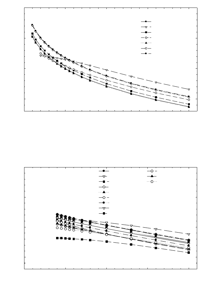
93
FIG. 9. Calculated k
Q
values for electron beams, for various cylindrical chamber types
calibrated in
60
Co gamma radiation.
k
Q
50101520
0.85
0.90
0.95
1.00
Beam quality index, R
50
(g/cm
2
)
Capintec PR06C
Exradin A2
Exradin T2
Exradin A12
NE 2571
NE 2581
PTW 30001
PTW 30002
PTW 30004
Victoreen 30-348
Victoreen 30-351
Victoreen 30-349
FIG. 8. Calculated k
Q
values for electron beams, for various plane-parallel chamber types
calibrated in
60
Co gamma radiation.
k
Q
0 5 10 15 20
0.85
0.90
0.95
1.00
Attix RMI 449
Capintec PS-033
Exradin P11
Holt (Memorial)
NACP/Calcam
Markus
Roos
Beam quality index, R
50
(g/cm
2
)

94
remaining calibration factors N
D,w,Q
are expressed as a series of factors k
Q,Q
o
using
the relation
(26)
If the quality of the user beam Q does not match any of the calibration qualities, the
value for k
Q,Q
o
to be used in Eq. (25) can be obtained by interpolation.
A chamber calibrated at a series of beam qualities may be subsequently recali-
brated at only the reference calibration quality Q
o
. In this case, the new value for
N
D,w,Q
o
should be used in conjunction with the values for k
Q,Q
o
measured previously.
Note, however, that this procedure should not be repeated more than twice in succes-
sion; the chamber should be recalibrated at all qualities at least every six years
31
,or
if the user suspects that the chamber has been damaged.
7.6. CROSS-CALIBRATION OF IONIZATION CHAMBERS
Cross-calibration refers to the calibration of a user chamber by direct compar-
ison in a suitable user beam against a reference chamber that has previously been
calibrated. A particular example of this is the cross-calibration of a plane-parallel
chamber for use in electron beams against a reference cylindrical chamber calibrated
in
60
Co gamma radiation. Despite the additional step, such a cross-calibration gener-
ally results in a determination of absorbed dose to water using the plane-parallel
chamber that is more reliable than that achieved by the use of a plane-parallel
chamber calibrated directly in
60
Co, mainly because problems associated with the
p
wall
correction for plane-parallel chambers in
60
Co, entering into the determination
of k
Q,Q
o
, are avoided. The modified k
Q,Q
o
factors to be used with a cross-calibrated
chamber are described in Section 3.2.1.
7.6.1. Cross-calibration procedure
The highest energy electron beam available should be used; R
50
> 7 g/cm
2
(E
o
16 MeV) is recommended. The reference chamber and the chamber to be
D,w,Q
Q,Q
o
D,w,Q
o
N
k=
N
31
As noted in Section 4.3, this procedure should not be used for chambers whose
stability has not been demonstrated over a period exceeding five years.

calibrated are compared by alternately positioning each at the reference depth z
ref
in
water in accordance with the reference conditions for each (see Table 17). The
calibration factor in terms of absorbed dose to water for the chamber under calibra-
tion, at the cross-calibration quality Q
cross
, is given by
(27)
where M
ref
Q
cross
and M
x
Q
cross
are the dosimeter readings for the reference chamber and
the chamber under calibration, respectively, corrected for the influence quantities
temperature and pressure, electrometer calibration, polarity effect and ion recombi-
nation as described in Section 4.4.3. N
ref
D,w,Q
o
is the calibration factor in terms of
absorbed dose to water for the reference chamber at quality Q
o
and k
ref
Q
cross
,Q
o
is the
beam quality correction factor for the reference chamber.
In practice, to minimize the effect of any variation in the accelerator output, the
readings M
ref
Q
cross
and M
ref
Q
cross
should be the averages and
respectively, measured relative to an external monitor. The external monitor should
ideally be positioned inside the phantom at the reference depth z
ref
, but displaced
laterally a distance of 3 or 4 cm from the chamber centre.
Normally, the calibration quality Q
o
for the reference chamber will be
60
Co and
the value for k
ref
Q
cross,
Q
o
is derived from Table 18. In the event that Q
o
is a high energy
electron beam, the value for k
ref
Q
cross,
Q
o
must be derived using the procedure of
Section 3.2.1:
(28)
where k
ref
Q
cross
Q
int
and k
ref
Q
o
,Q
int
are taken from Table 19.
7.6.2. Subsequent use of a cross-calibrated chamber
The cross-calibrated chamber with calibration factor N
x
D,w,Q
cross
may be used
subsequently for the determination of absorbed dose in a user beam of quality Q using
the basic Eq. (25):
D
w,Q
= M
x
Q
N
x
D,w,Q
cross
k
x
Q,Q
cross
(29)
ref
ref
cross int
cross
int
ref
Q,Q
Q,Q
o
Q,Q
o
k
k=
k
em
cross cross
x
QQ
M/M
ref
cross cross
x
QQ
M/M
ref
ref ref
cross
cross cross
cross
Q
x
D,w,Q D,w,Q Q ,Q
oox
Q
M
N=Nk
M
95

96
TABLE 19. CALCULATED VALUES FOR k
Q,Q
int
FOR VARIOUS CHAMBER TYPES CALIBRATED IN ELECTRON BEAMS, AS
A FUNCTION OF BEAM QUALITY R
50
(the data are derived using values for stopping-power ratios and perturbation factors as given in Appendix II and taking the value Q
int
= 7.5 g/cm
2
)
Beam quality R
50
(g/cm
2
)
1.0 1.4 2.0 2.5 3.0 3.5 4.0 4.5 5.0 5.5 6.0 7.0 8.0 10.0 13.0 16.0 20.0
Plane-parallel chambers
Attix RMI 449 1.078 1.068 1.055 1.047 1.040 1.034 1.028 1.023 1.019 1.014 1.010 1.003 0.997 0.986 0.972 0.961 0.948
Capintec PS-033 — — 1.016 1.015 1.014 1.013 1.012 1.010 1.009 1.007 1.006 1.002 0.998 0.990 0.978 0.968 0.955
Exradin P11 1.078 1.068 1.055 1.047 1.040 1.034 1.028 1.023 1.019 1.014 1.010 1.003 0.997 0.986 0.972 0.961 0.948
Holt (Memorial) 1.078 1.068 1.055 1.047 1.040 1.034 1.028 1.023 1.019 1.014 1.010 1.003 0.997 0.986 0.972 0.961 0.948
NACP/Calcam 1.078 1.068 1.055 1.047 1.040 1.034 1.028 1.023 1.019 1.014 1.010 1.003 0.997 0.986 0.972 0.961 0.948
Markus — — 1.038 1.032 1.028 1.024 1.020 1.017 1.014 1.011 1.008 1.003 0.997 0.988 0.976 0.965 0.952
Roos 1.078 1.068 1.055 1.047 1.040 1.034 1.028 1.023 1.019 1.014 1.010 1.003 0.997 0.986 0.972 0.961 0.948
Cylindrical chambers
Capintec PR06C — — — — — — 1.012 1.010 1.008 1.006 1.005 1.001 0.999 0.993 0.984 0.976 0.966
(Farmer)
Exradin A2 — — — — — — 1.003 1.003 1.002 1.002 1.002 1.001 0.999 0.996 0.991 0.984 0.975
(Spokas)
Exradin T2 — — — — — — 1.003 1.003 1.002 1.002 1.002 1.001 0.999 0.996 0.991 0.984 0.975
(Spokas)
Exradin A12 — — — — — — 1.012 1.010 1.008 1.006 1.005 1.002 0.998 0.993 0.984 0.976 0.965
(Farmer)
NE 2571 — — — — — — 1.012 1.010 1.008 1.006 1.005 1.001 0.999 0.993 0.984 0.976 0.966
(Guarded Farmer)
Ionization
chamber
type
a

97
TABLE 19. (cont.)
NE 2581 — — — — — — 1.012 1.010 1.008 1.006 1.005 1.001 0.999 0.993 0.984 0.976 0.966
(Robust Farmer)
PTW 30001/30010 — — — — — — 1.013 1.010 1.008 1.007 1.005 1.002 0.998 0.992 0.984 0.976 0.965
(Farmer)
PTW 30002/30011 — — — — — — 1.013 1.010 1.008 1.007 1.005 1.002 0.998 0.992 0.984 0.976 0.965
(Farmer)
PTW 30004/30012 — — — — — — 1.013 1.010 1.008 1.007 1.005 1.002 0.998 0.992 0.984 0.976 0.965
(Farmer)
PTW 31002/31003 — — — — — — 1.014 1.011 1.009 1.007 1.005 1.002 0.998 0.992 0.983 0.974 0.964
(flexible)
Victoreen 30-348 — — — — — — 1.015 1.013 1.010 1.008 1.006 1.002 0.998 0.991 0.982 0.973 0.962
Victoreen 30-351 — — — — — — 1.013 1.010 1.008 1.007 1.005 1.002 0.998 0.992 0.984 0.976 0.965
Victoreen 30-349 — — — — — — 1.008 1.006 1.005 1.004 1.003 1.001 0.999 0.995 0.988 0.980 0.971
a
Some of the chambers listed in this table fail to meet all of the minimum requirements described in Section 4.2.1. However, they have been included because of their
current clinical use.

98
The values for k
x
Q
cross
are derived using the procedure of Section 3.2.1:
(30)
where k
x
Q
int
and k
x
Q
cross
,Q
int
are taken from Table 19. Note that the above may also be
used for chambers calibrated at a standards laboratory at a single electron beam
quality Q
cross
.
7.7. MEASUREMENTS UNDER NON-REFERENCE CONDITIONS
7.7.1. Central axis depth dose distributions
The measurement of a central axis depth dose distribution should follow the
procedure given in Section 7.3.2 for the measurement of R
50
. If an ionization chamber
is used, the measured depth ionization distribution must be converted to a depth dose
distribution.
32
For a beam of quality R
50
, this is achieved by multiplying the ioniza-
tion current or charge at each measurement depth z by the stopping-power ratio s
w,air
at that depth. Values for s
w,air
are given in Table 20 as a function of R
50
and the relative
depth z/R
50
. Linear interpolation between table entries is sufficient. These stopping-
power ratios are calculated using Eq. (66) in Appendix II [91].
33
Note that this procedure neglects any variation in the perturbation factor with
depth. This is a good approximation for well guarded plane-parallel chamber types.
For plane-parallel chambers that are not well guarded and for cylindrical chamber
types, changes in the perturbation factor are significant and must be accounted for.
Unfortunately, the existing data on perturbation factors for these chamber types have
been verified only at depths close to the reference depth and are therefore not suitable
for use at other depths, despite their common use at these depths. The use of these
chambers to determine the depth dose distribution is therefore discouraged.
int
cross
cross int
Q,Q
Q,Q
QQ
x
x
x
,
k
k=
k
32
This conversion is required in electron beams because the water to air stopping-
power r
atio s
w,air
changes rapidly with depth.
33
Values for s
w,air
derived from the direct use of this equation by the user must be
verified by comparison with the values given in Table 20.

99
TABLE 20. SPENCER-ATTIX STOPPING-POWER RATIOS (∆ = 10 keV) WATER TO AIR (s
w,air
) FOR ELECTRON BEAMS, AS
A FUNCTION OF BEAM QUALITY R
50
AND RELATIVE DEPTH z/R
50
IN WATER
(the data are derived using Eq. (66) in Appendix II [91])
Beam quality R
50
(g/cm
2
)
1.0 1.4 2.0 2.5 3.0 3.5 4.0 4.5 5.0 5.5 6.0 7.0 8.0 10.0 13.0 16.0 20.0
z
ref
(g/cm
2
): 0.5 0.7 1.1 1.4 1.7 2.0 2.3 2.6 2.9 3.2 3.5 4.1 4.7 5.9 7.7 9.5 11.9
s
w,air
(z
ref
): 1.102 1.090 1.078 1.070 1.064 1.058 1.053 1.048 1.044 1.040 1.036 1.029 1.022 1.010 0.995 0.983 0.970
Relative depth
in water z/R
50
0.02 1.076 1.060 1.042 1.030 1.020 1.012 1.004 0.997 0.991 0.986 0.980 0.971 0.963 0.950 0.935 0.924 0.914
0.05 1.078 1.061 1.044 1.032 1.022 1.014 1.006 1.000 0.994 0.988 0.983 0.974 0.965 0.952 0.937 0.926 0.916
0.10 1.080 1.064 1.047 1.036 1.026 1.018 1.010 1.004 0.998 0.992 0.987 0.978 0.970 0.957 0.942 0.931 0.920
0.15 1.083 1.067 1.050 1.039 1.030 1.022 1.014 1.008 1.002 0.997 0.992 0.983 0.975 0.961 0.946 0.935 0.924
0.20 1.085 1.070 1.053 1.043 1.034 1.026 1.019 1.012 1.006 1.001 0.996 0.987 0.979 0.966 0.951 0.940 0.929
0.25 1.088 1.073 1.057 1.046 1.037 1.030 1.023 1.017 1.011 1.006 1.001 0.992 0.984 0.971 0.956 0.945 0.933
0.30 1.091 1.076 1.060 1.050 1.041 1.034 1.027 1.021 1.016 1.010 1.006 0.997 0.989 0.976 0.961 0.950 0.938
0.35 1.093 1.079 1.064 1.054 1.045 1.038 1.032 1.026 1.020 1.015 1.011 1.002 0.995 0.982 0.966 0.955 0.943
0.40 1.096 1.082 1.067 1.058 1.049 1.042 1.036 1.030 1.025 1.020 1.016 1.007 1.000 0.987 0.972 0.960 0.948
0.45 1.099 1.085 1.071 1.062 1.054 1.047 1.041 1.035 1.030 1.025 1.021 1.013 1.006 0.993 0.978 0.966 0.953
0.50 1.102 1.089 1.075 1.066 1.058 1.051 1.046 1.040 1.035 1.031 1.027 1.019 1.012 0.999 0.984 0.971 0.959
0.55 1.105 1.092 1.078 1.070 1.062 1.056 1.051 1.045 1.041 1.036 1.032 1.025 1.018 1.005 0.990 0.977 0.964
0.60 1.108 1.095 1.082 1.074 1.067 1.061 1.056 1.051 1.046 1.042 1.038 1.031 1.024 1.012 0.996 0.984 0.970
0.65 1.111 1.099 1.086 1.078 1.072 1.066 1.061 1.056 1.052 1.048 1.044 1.037 1.030 1.018 1.003 0.990 0.976
0.70 1.114 1.102 1.090 1.082 1.076 1.071 1.066 1.062 1.058 1.054 1.050 1.043 1.037 1.025 1.010 0.997 0.983
0.75 1.117 1.105 1.094 1.087 1.081 1.076 1.072 1.067 1.064 1.060 1.057 1.050 1.044 1.033 1.017 1.004 0.989

100
TABLE 20. (cont.)
0.80 1.120 1.109 1.098 1.091 1.086 1.081 1.077 1.073 1.070 1.066 1.063 1.057 1.051 1.040 1.025 1.012 0.996
0.85 1.123 1.112 1.102 1.096 1.091 1.087 1.083 1.080 1.076 1.073 1.070 1.064 1.059 1.048 1.033 1.019 1.004
0.90 1.126 1.116 1.107 1.101 1.096 1.092 1.089 1.086 1.083 1.080 1.077 1.072 1.067 1.056 1.041 1.028 1.011
0.95 1.129 1.120 1.111 1.106 1.102 1.098 1.095 1.092 1.090 1.087 1.085 1.080 1.075 1.065 1.050 1.036 1.019
1.00 1.132 1.124 1.115 1.111 1.107 1.104 1.101 1.099 1.097 1.095 1.092 1.088 1.083 1.074 1.059 1.045 1.028
1.05 1.136 1.127 1.120 1.116 1.113 1.110 1.108 1.106 1.104 1.102 1.100 1.096 1.092 1.083 1.069 1.055 1.037
1.10 1.139 1.131 1.125 1.121 1.118 1.116 1.115 1.113 1.112 1.110 1.109 1.105 1.102 1.093 1.079 1.065 1.046
1.15 1.142 1.135 1.129 1.126 1.124 1.123 1.122 1.120 1.119 1.118 1.117 1.114 1.111 1.104 1.090 1.075 1.056
1.20 1.146 1.139 1.134 1.132 1.130 1.129 1.129 1.128 1.128 1.127 1.126 1.124 1.121 1.115 1.101 1.086 1.066

101
7.7.2. Output factors
For a given electron beam, output factors should be measured at z
max
for the
non-reference field sizes and SSDs used for the treatment of patients. Output factors
may be determined as the absorbed dose at z
max
for a given set of non-reference
conditions relative to the absorbed dose at z
ref
(or z
max
) under the appropriate refer-
ence conditions. Users should be aware of the variation of the depth of maximum
dose, z
max
, particularly for small field sizes and high energies.
For detectors such as diodes, diamonds, etc., the output factor will be
adequately approximated by the detector reading under the non-reference conditions
relative to that under reference conditions. If an ionization chamber is used, the
measured ratio of corrected ionization currents or charges should be corrected for the
variation in s
w,air
with depth, using Table 20. The same considerations noted in
Section 7.7.1 regarding perturbation effects also apply here.
7.8. USE OF PLASTIC PHANTOMS
Plastic phantoms may only be used at beam qualities R
50
< 4 g/cm
2
(E
o
10 MeV). Their use is strongly discouraged, as in general they are responsible
TABLE 21. VALUES FOR THE DEPTH SCALING FACTOR c
pl
, THE
FLUENCE SCALING FACTOR h
pl
AND THE NOMINAL DENSITY ρ
pl
FOR
CERTAIN PLASTICS
Plastic phantom c
pl
h
pl
ρ
pl
(g/cm
3
)
Solid water (WT1) 0.949 1.011 1.020
Solid water (RMI-457) 0.949 1.008
a
1.030
Plastic water 0.982 0.998
b
1.013
Virtual water 0.946 —
c
1.030
PMMA 0.941 1.009 1.190
Clear polystyrene 0.922 1.026 1.060
White polystyrene
d
0.922 1.019 1.060
A-150 0.948 —
c
1.127
a
Average of the values given in Ref. [95] below 10 MeV.
b
Average of the values given in Ref. [65] below 10 MeV.
c
Data not available.
d
Also referred to as high impact polystyrene.

for the largest discrepancies in the determinations of absorbed dose in electron beams.
Nevertheless, when accurate chamber positioning in water is not possible, or when no
waterproof chamber is available, their use is permitted. The criteria determining the
choice of plastic are discussed in Section 4.2.3.
7.8.1. Scaling of depths
Depths in plastic phantoms, z
pl
, expressed in g/cm
2
, are obtained by multiplying
the depth in centimetres by the plastic density
ρ
pl
in g/cm
3
. The density of the plastic,
ρ
pl
, should be measured for the batch of plastic in use rather than using a nominal
value for the plastic type. Measurements made in a plastic phantom at depth z
pl
relate
to the depth in water given by
z
w
= z
pl
c
pl
g/cm
2
(z
pl
in g/cm
2
) (31)
where c
pl
is a depth scaling factor. Values for c
pl
for certain plastics are given in
Table 21 [93–95].
34
Nominal values for the density
ρ
pl
for each plastic are also given
in the table. These are given only for guidance.
7.8.2. Plastic phantoms for beam quality specification
If a plastic phantom is used to measure the beam quality specifier, the measured
quantity is the half-value of the depth ionization distribution in the plastic, R
50,ion,pl
.
The R
50,ion
in water is obtained using Eq. (31); that is
R
50,ion
= R
50,ion,pl
c
pl
g/cm
2
(R
50,ion,pl
in g/cm
2
)
35
(32)
The beam quality specifier R
50
in water is then obtained using Eq. (23).
102
34
In this Code of Practice, the depths z
w
and z
pl
are defined in units of g/cm
2
, in con-
trast to their definition in centimetres in Ref. [21]. The depth scaling factor c
pl
is the ratio of
the average depth of electron penetration in water and plastic [93, 94], where these depths are
also expressed in g/cm
2
. As a result of this change of units, and to a lesser extent the incorpo-
ration of new data, the values given for c
pl
in Table 21 differ from those for C
pl
given in
Table VIII of Ref. [21]. The use of lowercase for c
pl
denotes the use of these factors only with
depths expressed in g/cm
2
.
35
Strictly, c
pl
factors apply only to depth dose distributions and their use in scaling
depth ionization distributions is an approximation.

7.8.3. Plastic phantoms for absorbed dose determination at z
ref
To determine the absorbed dose to water at z
ref
in water using a plastic phantom,
the chamber must be positioned at the scaled reference depth z
ref,pl
in the plastic. This
is obtained from z
ref
in water using Eq. (31) in inverse form; that is
z
ref,pl
=z
ref
/c
pl
g/cm
2
(z
ref
in g/cm
2
) (33)
All other reference conditions are as in Table 17. In addition to depth scaling,
the dosimeter reading M
Q,pl
at depth z
ref,pl
in the plastic must be scaled to the equiv-
alent reading M
Q
at z
ref
in water using the relation
M
Q
= M
Q,pl
h
pl
(34)
Values for the fluence scaling factor h
pl
for certain plastics are given in
Table 21.
36
The uncertainty associated with this scaling is the main reason for
avoiding the use of plastic phantoms. The absorbed dose to water at z
ref
in water
follows from the value for M
Q
given by Eq. (34) and the use of Eq. (25).
7.8.4. Plastic phantoms for depth dose distributions
When using a plastic phantom to determine the depth dose distribution, each
measurement depth in plastic must be scaled using Eq. (31) to give the appropriate
depth in water. The dosimeter reading at each depth must also be scaled using
Eq. (34). For depths beyond z
ref,pl
(as given by Eq. (33)) it is acceptable to use the
value for h
pl
at z
ref,pl
derived from Table 21. At shallower depths, this value for h
pl
should be decreased linearly to a value of unity at zero depth; this ignores the effect
of backscatter differences at the surface.
If an ionization chamber is used, the measured depth ionization distribution
must be converted to a depth dose distribution. This is achieved by multiplying the
ionization current or charge at each depth by the appropriate stopping-power ratio
s
w,air
, as described in Section 7.7.1.
103
36
In Ref. [21], values for h
pl
are given as a function of energy. In this Code of Practice,
plastic phantoms may only be used for R
50
< 4 g/cm
2
(E
o
10 MeV) and in this energy range
the value for h
pl
for a given plastic can be taken as a constant to an acceptable accuracy.

7.9. ESTIMATED UNCERTAINTY IN THE DETERMINATION OF
ABSORBED DOSE TO WATER UNDER REFERENCE CONDITIONS
Uncertainty estimates are presented in two tables: Table 22 for determinations
of absorbed dose based on a
60
Co calibration factor and Table 23 for determinations
of absorbed dose based on calibration in a high energy electron beam with
R
50
~10 g/cm
2
(E
o
~23 MeV). In each table, estimates are given for both plane-parallel
and cylindrical chamber types (note that R
50
must not be less than 4 g/cm
2
when a
cylindrical chamber is used). Uncertainty estimates are not given for the
104
TABLE 22. ESTIMATED RELATIVE STANDARD UNCERTAINTY
a
OF D
w,Q
AT
THE REFERENCE DEPTH IN WATER AND FOR AN ELECTRON BEAM,
BASED ON A CHAMBER CALIBRATION IN
60
Co GAMMA RADIATION
Physical quantity or procedure
Relative standard uncertainty (%)
User chamber type: Cylindrical Plane parallel
Beam quality range: R
50
≥ 4 g/cm
2
R
50
≥ 1 g/cm
2
Step 1: Standards laboratory
N
D,w
calibration of secondary standard at PSDL 0.5 0.5
Long term stability of secondary standard 0.1 0.1
N
D,w
calibration of user dosimeter at SSDL 0.4 0.4
Combined uncertainty of step 1
b
0.6 0.6
Step 2: User electron beam
Long term stability of user dosimeter 0.3 0.4
Establishment of reference conditions 0.4 0.6
Dosimeter reading M
Q
relative to beam monitor 0.6 0.6
Correction for influence quantities k
i
0.4 0.5
Beam quality correction k
Q
(calculated values) 1.2 1.7
Combined uncertainty of step 2 1.5 2.0
Combined standard uncertainty of D
w,Q
(steps 1+2) 1.6 2.1
a
See the ISO Guide for the expression of uncertainty [32], or Appendix IV. The estimates given
in the table should be considered typical values; these may vary depending on the uncertainty
quoted by standards laboratories for calibration factors and on the experimental uncertainty
at the user’s institution.
b
A user chamber calibrated directly at a PSDL will have a slightly smaller uncertainty for
step 1. However, this has no significant effect on the combined uncertainty of the determina-
tion of absorbed dose to water in the user reference beam.

determination of absorbed dose at depths other than z
ref
, although these may be large
when plastic phantoms are used. The uncertainty of the k
Q,Q
o
factors is discussed in
Appendix II.
If measured values for k
Q,Q
o
are used instead of calculated values, the combined
uncertainty in the determination of absorbed dose to water may be considerably
reduced. For example, if values for k
Q
(that is, relative to
60
Co) are measured for a
plane-parallel chamber with a standard uncertainty of around 0.8%, the estimated
overall uncertainty in the determination of the absorbed dose to water at z
ref
in an
electron beam is reduced from 2.1 to 1.5%.
The uncertainty in the determination of the absorbed dose to water based on a
plane-parallel chamber cross-calibrated in a high energy electron beam (against a
cylindrical chamber having an absorbed dose to water calibration factor in a
60
Co
105
TABLE 23. ESTIMATED RELATIVE STANDARD UNCERTAINTY
a
OF D
w,Q
AT
THE REFERENCE DEPTH IN WATER AND FOR AN ELECTRON BEAM,
BASED ON A CHAMBER CALIBRATION IN A HIGH ENERGY ELECTRON
BEAM
Physical quantity or procedure
Relative standard uncertainty (%)
User chamber type: Cylindrical Plane parallel
Beam quality range: R
50
≥ 4 g/cm
2
R
50
≥ 1 g/cm
2
Step 1: PSDL
N
D,w
calibration of user dosimeter at PSDL 0.7 0.7
Combined uncertainty in step 1 0.7 0.7
Step 2: User electron beam
Long term stability of user dosimeter 0.3 0.4
Establishment of reference conditions 0.4 0.6
Dosimeter reading M
Q
relative to beam monitor 0.6 0.6
Correction for influence quantities k
i
0.4 0.5
Beam quality correction k
Q,Q
o
(calculated values) 0.9 0.6
Combined uncertainty in step 2 1.3 1.2
Combined standard uncertainty of D
w,Q
(steps 1+2) 1.4 1.4
a
See the ISO Guide for the expression of uncertainty [32], or Appendix IV. The estimates
given in the table should be considered typical values; these may vary depending on the
uncertainty quoted by standards laboratories for calibration factors and on the experimental
uncertainty at the user’s institution.

106
beam) deserves special attention because cancellations must be taken into account.
Combining Eq. (29) (the use of a cross-calibrated chamber), Eq. (27) (the cross-
calibration factor) and Eq. (4) (the basic equation for k
Q
), the full expression for the
absorbed dose to water is
(35)
where for clarity the subscript denoting the reference quality ‘Co-60’ has been expli-
citly written (instead of Q
o
). Note here that the s
w,air
and W
air
in Q
cross
do not appear
because of cancellation. The three chamber readings will be correlated to some
extent, and a combined uncertainty of 0.8% for all three seems reasonable. The uncer-
tainty of N
D,w,Co-60
is 0.6%. The ratios of the stopping-power ratios s
w,air
and W
air
are
each 0.5% (see Table 40 in Appendix II). The ratio of perturbation factors p for the
plane-parallel chamber in two electron qualities is 0.4 % (the four components of
Table 41 in Appendix II). The ratio of perturbation factors p for the cylindrical
chamber is 1.0 % (the four components of Table 40). Thus, a consistent approximate
estimate of the combined uncertainty of D
w,Q
is 1.6 %.
()
()
()
()
cyl
cyl
cross cross
cross cross
cyl
air
air
Co-60
cyl
air
air
Co-60
Co-60
Co-60
pp
w,
pp
w,Q D,w,
pp pp
w,
QQ
QQQ
Q
QQ
s
W
Mp
p
D=M N
W
s
Mpp

107
7.10. WORKSHEET
Determination of the absorbed dose to water in an electron beam
User: ___________________________________________________ Date: _______________
1. Radiation treatment unit and reference conditions for D
w,Q
determination
Accelerator: Nominal energy: MeV
Nominal dose rate:
MU/min Measured R
50
: g/cm
2
Reference phantom: ❏ water ❏ plastic obtained from ❏ ionization ❏ dose curves
Reference field size: cm × cm Reference SSD: 100 cm
Beam quality, Q (R
50,w
): _______ g/cm
2
Reference depth z
ref,w
= 0.6 R
50
– 0.1: g/cm
2
2. Ionization chamber and electrometer
Ionization chamber model: ___________________ Serial No.: _________ Type: ❏ pp ❏ cyl
Chamber wall/window material: thickness: g/cm
2
Waterproof sleeve/cover material: thickness: g/cm
2
Phantom window material: thickness: g/cm
2
Absorbed dose to water calibration factor
a
N
D,w,Q
o
= ❏ Gy/nC ❏ Gy/rdg
Calibration quality Q
o
: ❏
60
Co ❏ electron beam Calibration depth: g/cm
2
If Q
o
is electron beam, give R
50
: g/cm
2
Reference conditions for calibration P
o
: kPa T
o
: °C Rel. humidity:
%
Polarizing potential V
1
: V Calibration polarity: ❏ +ve ❏ –ve ❏ corrected for polarity
User polarity: ❏ +ve ❏ –ve
effect
Calibration laboratory: Date:
Electrometer model: Serial No.:
Calibrated separately from chamber: ❏ Yes ❏ No Rating setting:
If yes, calibration laboratory:
Date:
3. Phantom
Water phantom window material:
thickness: g/cm
2
Plastic phantom phantom material:
density: g/cm
3
depth scaling factor c
pl
: reference depth z
ref,pl
= z
ref
/c
pl
: g/cm
2
fluence scaling factor
b
: h
pl
=
4. Dosimeter reading
c
and correction for influence quantities
Uncorrected dosimeter reading at V
1
and user polarity: ❏ nC ❏ rdg
Corresponding accelerator monitor units: MU
Ratio of dosimeter reading and monitor units: M
1
= ❏ nC/MU ❏ rdg/MU
108
(i) Pressure P: _________ kPa Temperature T: _______ °C Rel. humidity (if known): ____ %
_________________
(ii) Electrometer calibration factor
d
k
elec
: ❏ nC/rdg ❏ dimensionless k
elec
= _____________
(iii) Polarity correction
e
rdg at + V
l
:M
+
= _____________ rdg at –V
l
: M
–
= _____________
____________________
(iv) Recombination correction (two voltage method)
Polarizing voltages: V
l
(normal) = ____________ V V
2
(reduced) = ______________ V
Readings
f
at each V: M
1
= M
2
=
Voltage ratio V
1
/V
2
= ________________________ Ratio of readings M
1
/M
2
= ____________
Use Table 9 for a beam of type: ❏ pulsed ❏ pulsed–scanned
a
0
= a
1
= a
2
=
______
g,h
Corrected dosimeter reading at the voltage V
1
:
M
Q
= M
1
h
pl
k
TP
k
elec
k
pol
k
s
= ______________________ ❏ nC/MU ❏ rdg/MU
5. Absorbed dose to water at the reference depth, z
ref
Beam quality correction factor for user quality Q:
If Q
o
is
60
Co, Table 18 gives k
Q,Q
o
=
If Q
o
is electron beam, Table 19 gives k
Q,Q
int
= k
Q
o
,Q
int
=
If k
Q,Q
o
derived from series of electron beam calibrations k
Q,Q
o
=
Calibration laboratory: Date:
D
w,Q
(z
ref
) = M
Q
N
D,w,Q
o
k
Q,Q
o
= Gy/MU
6. Absorbed dose to water at the depth of dose maximum, z
max
Depth of dose maximum: z
max
= g/cm
2
Percentage depth dose at z
ref
for a cm × cm field size: PDD(z
ref
= g/cm
2
) = %
Absorbed dose calibration of monitor at z
max
:
D
w,Q
(z
max
) = 100 D
w,Q
(z
ref
)/PDD(z
ref
) = Gy/MU
a
Note that if Q
o
is
60
Co, N
D,w,Q
o
is denoted by N
D,w
.
b
If a water phantom is used, set the fluence scaling factor h
pl
= 1.
c
All readings should be checked for leakage and corrected if necessary.
d
If the electrometer is not calibrated separately, set k
elec
= 1.
int
int
Q,Q
Q,Q
o
Q,Q
o
k
k= =
k
kaa
M
M
a
M
M
s
=+
Ê
Ë
Á
ˆ
¯
˜
+
Ê
Ë
Á
ˆ
¯
˜
=
01
1
2
2
1
2
2
+–
pol
M+M
k= =
2 M
k
T
T
P
P
TP
o
o
=
+
+
=
(. )
(. )
273 2
273 2
109
e
M in the denominator of k
pol
denotes reading at the user polarity. Preferably, each reading in the equation
should be the average of the ratios of M (or M
+
or M
–
) to the reading of an external monitor, M
em
.
It is assumed that the calibration laboratory has performed a polarity correction. Otherwise k
pol
is
determined according to:
rdg at +V
1
for quality Q
o
: M
+
= ___________ rdg at –V
1
for quality Q
o
: M
–
= _____________
___________
f
Strictly, readings should be corrected for polarity effect (average with both polarities). Preferably, each
reading in the equation should be the average of the ratios of M
1
or M
2
to the reading of an external
monitor, M
em
.
g
Check that
h
It is assumed that the calibration laboratory has performed a recombination correction. Otherwise the
factor k
′
s
= k
s
/k
s,Q
o
should be used instead of k
s
. When Q
o
is
60
Co, k
s,Q
o
(at the calibration laboratory) will
normally be close to unity and the effect of not using this equation will be negligible in most cases.
s
MM
k
VV
12
12
1
1
1
-
-ª
-
()
()
pol
+–
+–
Q
Q
0
M+M M
k= =
M+M M
È˘
Î˚
È˘
Î˚
110
8. CODE OF PRACTICE FOR
LOW ENERGY KILOVOLTAGE X RAY BEAMS
8.1. GENERAL
This section provides a Code of Practice for reference dosimetry (beam
calibration) and recommendations for relative dosimetry in X ray beams with half-
value layers of up to 3 mm of aluminium and generating potentials of up to 100 kV.
It is based upon a calibration factor in terms of absorbed dose to water N
D,w,Q
o
for a
dosimeter in a reference beam of quality Q
o
.
This range of beam qualities is referred to here as the low energy X ray range.
The division into low and medium energy ranges (the latter presented in Section 9)
is intended to reflect the two distinct types of radiation therapy for which kilo-
voltage X rays are used, ‘superficial’ and ‘deep’ (‘orthovoltage’). The boundary
between the two ranges defined in this section and the next is not strict and has an
overlap between 80 kV, 2 mm Al and 100 kV, 3 mm Al. In the overlap region the
methods of either section are equally satisfactory and whichever is more convenient
should be used.
There is a limited availability of standards of absorbed dose to water in the
kilovoltage X ray range. However, it is possible to derive calibration factors in
terms of absorbed dose to water from air kerma calibration factors using one of the
accepted codes of practice (see Appendix I). Thus any calibration laboratory with
standards of air kerma can in this way provide derived calibrations in terms of
absorbed dose to water. Even though this is formally equivalent to the user
obtaining an air kerma calibration and individually applying the same air kerma
code of practice, it has the advantage of permitting the widespread use of the uni-
fied methodology presented here, in a field of dosimetry where standard methods
are notably lacking.
The dosimetry of low energy X rays has traditionally been based on measure-
ments in air of exposure or air kerma. The absorbed dose at the surface of water is
derived from this measurement by converting exposure or air kerma to absorbed dose
to water and applying a correction factor for the effect of backscatter. This is still the
basis of most current dosimetry codes of practice for low energy X rays [17, 96, 97].
The IAEA Code of Practice [17] also includes the option of basing the dosimetry on
measurements made in a full scatter phantom, using a chamber that has been
calibrated directly in terms of absorbed dose to water while mounted in the phantom.
This is the approach taken in the present Code of Practice, expressed in terms of the
formalism given in Section 3.

8.2. DOSIMETRY EQUIPMENT
8.2.1. Ionization chambers
The recommendations regarding ionization chambers given in Section 4.2.1
should be followed. The chamber should be of a type designed for use with low
energy X rays, as given in Table 5. The chamber window thickness should be
sufficient to allow full buildup of the secondary electron spectrum. This will also
prevent secondary electrons generated upstream from entering the chamber. If the
chamber is to be used with X rays 50 kV or above it will usually be necessary to add
foils of similar material to the chamber window to ensure full buildup. The total thick-
ness required (including the thickness of the chamber wall) is given for various
plastics in Table 24. If the exact thickness in the table can not be matched, then a
slightly thicker foil should be used, because while the attenuation of the X rays from
the additional thickness is negligible, full buildup will be assured.
The reference point of the chamber for the purpose of calibration at the standards
laboratory and for measurements under reference conditions in the user beam is taken
to be on the outside of the chamber window at the window centre (or the outside of the
buildup foil if this is used). This point is positioned so that it is flush with the front
surface of the phantom. The chamber and phantom and any buildup foils should be
calibrated together at the standards laboratory at the same SSD and field size used for
111
TABLE 24. TOTAL THICKNESS
a
OF MATERIAL REQUIRED FOR FULL
BUILDUP
kV
Polyethylene PMMA
b
Mylar
mg/cm
2
mm mg/cm
2
mm mg/cm
2
mm
50 4.0 45 4.4 40 4.6 35
60 5.5 60 6.1 50 6.4 45
70 7.2 80 8.0 65 8.3 60
80 9.1 100 10.0 85 10.5 75
90 11.1 120 12.2 105 12.9 90
100 13.4 140 14.7 125 15.4 110
a
The thickness specified is taken to be equal to the csda range of the maximum energy
secondary electrons, as given in Ref. [66].
b
Polymethyl methacrylate, also known as acrylic. Trade names are Lucite, Plexiglas or
Perspex.

112
reference dosimetry in the clinic. Because of large chamber to chamber variations in
energy response, it is not recommended that a generic set of k
Q,Q
o
values for a particular
type of chamber be used.
8.2.2. Phantoms
The recommendations regarding phantoms given in Sections 4.2.3 and 4.2.4
should be followed. The phantom must permit the chamber to be mounted with the
outside face of the chamber window flush with the phantom surface. This is normally
not possible using a water phantom and so a plastic phantom should be used. The use
of a water equivalent material designed for use in kilovoltage X rays is ideal but
PMMA (Perspex, Lucite, etc.) is acceptable.
37
Because the phantom/chamber unit is
calibrated in terms of absorbed dose to water at the surface, no dose or depth conver-
sions are needed, irrespective of the type of plastic used. The phantom should extend
in the beam direction by at least 5 g/cm
2
and in the lateral direction at least far enough
beyond the reference field size used to ensure that the entire primary beam exits
through the rear face of the phantom.
8.3. BEAM QUALITY SPECIFICATION
8.3.1. Choice of beam quality index
It has long been known that it is desirable to use more than one beam quality
parameter to characterize a kilovoltage X ray spectrum for dosimetry [98, 99]. The
usual quantities used are the kilovoltage generating potential (kV) and the half-value
layer (HVL). However, it is often not possible to match both the kV and HVL of each
clinical beam with the beams of the standards laboratory. Therefore, the primary
beam quality index has traditionally been the HVL. This is the beam quality index
used in this Code of Practice for low energy X rays.
37
PMMA is acceptable for a phantom that is used only for measurements at the surface.
This is because the phantom needs to reproduce only the backscatter, and not the attenuation
or scatter at depth. The chamber is calibrated in the phantom under the reference conditions of
field size and SSD, and so as long as these are similar to the reference conditions in the clinic,
any difference between PMMA and water will be very small. For the measurement of output
factors at other field sizes and SSDs, it is only the ratio of the backscatter at the different
geometries which must be similar to that of water. Even though PMMA is not water equivalent,
the backscatter is typically an order of magnitude less than the absorbed dose at the surface,
and the difference in backscatter between water and PMMA is another order of magnitude less
again. The overall disagreement is therefore typically no more than 1%.
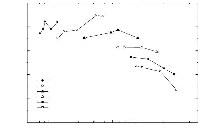
113
In spite of the fact that previous dosimetry protocols for kV X rays have used
HVL only as the quality index, these protocols have not included any discussion on
the uncertainty arising from this choice. This is a component of uncertainty which
should not be overlooked. Unfortunately, there is insufficient published experimental
work to indicate how calibration factors in terms of absorbed dose to water will vary
independently with HVL and kV. Some indication may be gained from the air kerma
calibration factor N
K,Q
for a PTW M23342 chamber over the range of typical beams
used for therapy (see Fig. 10). For a given HVL, the calibration factor varies over a
range of up to a little over 2%. However, this is not truly indicative of the variation of
N
D,w
because it does not take account of the response of the chamber to scatter from
the phantom, or the factor to convert from air kerma to dose to water. One can only
conjecture that the variation in N
D,w,Q
will be similar to that of N
K,Q
. A conservative
figure of 1.5% is taken as the type B standard uncertainty (see Appendix IV.3) for the
types of chamber recommended in this Code of Practice.
It should be noted that the concept of HVL is based on the response of a
dosimeter to air kerma. The development of a new quality index for kV X rays based
on the quantity absorbed dose to water (possibly a ratio of doses at different depths)
that can be adopted by future versions of this Code of Practice would be welcomed.
FIG. 10. Air kerma calibration factors for a PTW M23342 chamber as a function of
generating potential and HVL in the range 15–100 kV. Data measured at NRL.
0.05 0.1 0.5 1 5
1.02
1.04
1.06
1.08
1.10
1.12
N
K,Q
for a PTW M23342 chamber
15 kV
30 kV
50 kV
55 kV
70 kV
100 kV
N
K,Q
(Gy/nC
1
)
HVL (mm Al)

114
It is of course preferable, where possible, to have the dosimeter calibrated at the
same combinations of kV and HVL as those of the user clinical beams. But if this is
not possible, calibration data should be obtained for beams with lesser and greater
HVLs and the desired values derived by interpolation (see the worksheet).
8.3.2. Measurement of beam quality
The conventional material used for the determination of the HVL in low energy
X ray beams is aluminium. The HVL is defined as the thickness of an absorber which
reduces the air kerma rate of a narrow X ray beam at a reference point distant from the
absorbing layer to 50% compared with the air kerma rate for the non-attenuated beam.
Because of the absorption of low energy X rays in air, the HVL varies with the
distance from the X ray target. Therefore, the HVL for low energy X ray beams should,
as far as possible, be measured with the chamber at the same SCD as will be used for
measurements of absorbed dose. If the distance from the target to the chamber is less
than 50 cm, scatter from the added filters may affect the result. This can be checked
by using different field sizes and extrapolating to zero field size if necessary.
The ideal arrangement is to place at about half the distance between the X ray
target and the chamber a collimating aperture that reduces the field size to just enough
to encompass the whole of the chamber. There should be no other scattering material
in the beam up to 1 m behind the chamber. The filters added for the HVL measure-
ment are placed close to the aperture in combinations of thickness which span the
HVL thickness to be determined. The thickness that reduces the air kerma rate to one
half is obtained by interpolation.
Strictly, it is the ionization current or integrated charge per exposure time that
is measured, not the air kerma rate. This distinction is particularly relevant for lightly
filtered beams. A thin walled chamber with an energy response that varies less than
2% over the quality range measured should be used.
38
If required, a buildup foil
should be added to the chamber window as described in Section 8.2.1.
A monitor chamber should be used to prevent misleading results due to the
variation in X ray output. Care must be taken so that the response of the monitor
chamber is not affected by increasing scatter as more filters are placed in the beam.
If a monitor chamber is not available, the effects of output variation can be minimized
38
HVL measurement errors of up to 10% can result using a Farmer type chamber in a
lightly filtered 100 kV beam. If the chamber energy response varies by more than 2% over the
quality range, then each measurement must be converted to an air kerma measurement using
an air-kerma calibration factor appropriate for each filtered or unfiltered beam. This is an
iterative process because the calibration factor itself is determined by the HVL.

by randomizing the measurement sequence and measuring the air kerma rate without
additional filters both at the beginning and at the end.
The purity of aluminium used for HVL measurements should be 99.9%. For
further guidance on HVL determination see Refs [33, 71, 98, 100].
8.4. DETERMINATION OF ABSORBED DOSE TO WATER
8.4.1. Reference conditions
The reference conditions for the determination of absorbed dose to water are
given in Table 25.
8.4.2. Determination of absorbed dose under reference conditions
The general formalism is given in Section 3. The absorbed dose to water at the
water surface, in a low energy X ray beam of quality Q and in the absence of the
chamber, is given by
D
w,Q
= M
Q
N
D,w,Q
o
k
Q,Q
o
(36)
115
TABLE 25. REFERENCE CONDITIONS FOR THE DETERMINATION OF
ABSORBED DOSE IN LOW ENERGY X RAY BEAMS
Influence quantity Reference value or reference characteristics
Phantom material Water equivalent plastic or PMMA
Chamber type Plane-parallel for low energy X rays
Measurement depth z
ref
Phantom surface
Reference point of the chamber At the centre of outside surface of chamber window
or additional buildup foil if used
a
SSD Usual treatment distance as determined by the
reference applicator
b
Field size 3 cm × 3 cm, or 3 cm diameter, or as determined by
the reference applicator
b
a
The reference point of the chamber is the outside surface because the calibration factor N
D,w,Q
is given in terms of the absorbed dose to the surface of water.
b
An applicator with a field size equal to (or otherwise minimally larger than) the reference
field size should be chosen as the reference applicator.

where M
Q
is the reading of the dosimeter with the reference point of the chamber
positioned at z
ref
in accordance with the reference conditions given in Table 25 and
corrected for the influence quantities temperature and pressure, and electrometer
calibration, as described in the worksheet (see also Section 4.4.3). Note that the
polarity and ion recombination corrections are difficult to measure on the type of
chamber recommended for low energy X rays due to electrostatic distortion of the
chamber window. However, the effects will be negligible as long as the polarity is
kept the same as was used for calibration and the absorbed dose rate is less than a few
grays per second (see Ref. [101]). N
D,w,Q
o
is the calibration factor in terms of
absorbed dose to water for the dosimeter at the reference quality Q
o
and k
Q,Q
o
is a
chamber specific factor which corrects for differences between the reference beam
quality Q
o
and the actual beam quality being used, Q. Note also that the correction
for timer error may be significant. It is not a multiplicative correction, and is there-
fore treated separately in the worksheet.
8.5. VALUES FOR k
Q,Q
o
It is not possible to calculate values of k
Q,Q
o
using Bragg–Gray theory because
a thin-walled chamber on the surface of a phantom does not represent a Bragg–Gray
cavity. Therefore, the values for k
Q,Q
o
must be obtained directly from measurements.
Generic values, measured for a particular chamber type, should not be used because
of large chamber to chamber variations in energy response.
The calibration data for the dosimeter should ideally be presented as a single
calibration factor N
D,w,Q
o
determined in a reference beam of quality Q
o
and one or
more measured factors k
Q,Q
o
corresponding to the other calibration qualities, Q.
However, if the calibration data are in the form of a set of calibration factors N
D,w,Q
then one of the qualities should be chosen as the reference beam quality Q
o
.
39
The
corresponding calibration factor becomes N
D,w,Q
o
and the other calibration factors
N
D,w,Q
are expressed in terms of k
Q,Q
o
using the relation
(37)
D,w,Q
Q,Q
o
D,w,Q
o
N
k=
N
116
39
The choice here is not critical; the quality corresponding to the N
D,w,Q
factor with the
smallest uncertainty is appropriate, otherwise a quality close to the middle of the range.
If the quality of the user beam does not match any of the calibration qualities, the
value for k
Q,Q
o
to be used in Eq. (36) can be interpolated (see worksheet).
A chamber calibrated in a series of beam qualities may be subsequently recali-
brated at only the reference quality Q
o
. In this case the new value for N
D,w,Q
o
should
be used with the values of k
Q,Q
o
previously measured. However, because of the
particular susceptibility of ionization chambers to change in energy response to low
energy X rays, it is preferable that chambers are recalibrated at all qualities each time.
In particular, if N
D,w,Q
o
changes by an amount more than the uncertainty stated for the
calibration, or there have been any repairs to the chamber, then the dosimeter should
be re-calibrated at all qualities.
8.6. MEASUREMENTS UNDER NON-REFERENCE CONDITIONS
8.6.1. Central axis depth dose distributions
An estimate of depth dose distributions may be obtained from the literature
[81]. However if desired, the depth dose distribution can be measured by using the
same chamber as that used for reference dosimetry and a water equivalent phantom.
Thin sheets of water equivalent phantom material designed for use with kilo-
voltage X rays are placed over the chamber in its phantom and the phantom is moved
back by the same amount to maintain a constant SSD. The manufacturer’s specifications
for the material should state that it is equivalent to water within a few per cent in the
energy range of interest. This should be verified by comparison with published data.
PMMA is not suitable for measurement of depth dose distributions, even if it is used as
the phantom material for reference dosimetry. Strictly, this procedure provides a depth
ionization distribution rather than the depth dose distribution. However, if the response
of the chamber is reasonably constant (within 5%) with beam quality, the error intro-
duced by assuming that the depth dose distribution is the same as the depth ionization
distribution is not likely to be more than a few per cent at any clinically relevant depth.
8.6.2. Output factors
For clinical applications, output factors are required for all combinations of SSD
and field size used for radiotherapy treatments. The output factor is the ratio of the cor-
rected dosimeter reading at the surface for a given set of non-reference conditions to
that for the reference conditions (reference conditions are given in Table 25).
Because of the significant scatter contribution from the inside of an applicator,
it is not sufficiently accurate to estimate output factors for different applicators using
the ratio of the backscatter factors corresponding to the respective field sizes. The
output factor must be measured for each beam quality and each individual applicator.
117
If a PMMA phantom is used, the response of the chamber to different field sizes
will not be exactly the same as that for a water phantom, owing to the difference in
backscatter (see footnote 37). However, because the output factor is a ratio of
measurements, this effect should not incur an error of greater than 1%, particularly if
the reference field size is in the middle of the range of sizes used clinically.
8.7. ESTIMATED UNCERTAINTY IN THE DETERMINATION OF
ABSORBED DOSE TO WATER UNDER REFERENCE CONDITIONS
There is to date very little practical experience in primary standards of absorbed
dose for low energy X rays. The uncertainty in N
D,w,Q
determined directly from a
primary standard is assumed here to be 1%. Alternatively, if the calibration factor in
terms of absorbed dose to water is derived from a standard of air kerma, the uncer-
tainty in the determination of N
D,w,Q
is estimated as 3%. In the latter case, the uncer-
tainty of N
D,w,Q
then dominates the overall uncertainty.
The stability of a good dosimeter over a series of readings is typically better
than 0.1%, but the temperature of the chamber may be uncertain to at least ±1°C
because of heating from the X ray tube. The X ray output from some machines
depends on line voltage, tube temperature, and operator control of tube current and
voltage. This variation is minimized when the exposures are controlled by a monitor
chamber, but this is rarely the case on dedicated low energy X ray machines where
the variation in output over a series of identical exposure times may be as much as
5%. This uncertainty should be separately estimated by the user from the standard
deviation of a set of at least five exposures of typical treatment length. It is not
included in this analysis.
Because the SSD is often very short on a low energy X ray machine, there may
be difficulty in achieving a positioning reproducibility that results in an uncertainty in
the determination of absorbed dose to water better than 1%, so this uncertainty is
assigned to establishment of reference conditions.
For low energy X ray dosimetry, the values for k
Q,Q
o
are derived directly from
the calibration factors N
D,w,Q
. If the value of N
D,w,Q
o
used in Eq. (36) is the same as
that used in Eq. (37), then the uncertainty in the product k
Q,Q
o
N
D,w,Q
o
is just the
uncertainty in N
D,w,Q
together with an additional 1.5% to account for the uncertainty
of matching the calibration and user beams on the basis of HVL. However, if the
N
D,w,Q
o
used in Eq. (36) is different because it has been obtained from a subsequent
calibration of the dosimeter, then the uncertainty in k
Q,Q
o
is increased because of the
lack of correlation between the new N
D,w,Q
o
and that used to calculate the k
Q,Q
o
. This
results in an increase in the combined standard uncertainty of D
w,Q
of about 0.2%.
The uncertainties are summarized in Table 26.
118

119
TABLE 26. ESTIMATED RELATIVE STANDARD UNCERTAINTY
a
OF D
w,Q
AT THE REFERENCE DEPTH IN WATER FOR A LOW ENERGY X RAY BEAM
Physical quantity or procedure Relative standard uncertainty (%)
Step 1: Standards laboratory SSDL SSDL PSDL PSDL
N
D,w,Q
o
or N
K
calibration of secondary 1.0 0.5
standard at PSDL
Long term stability of secondary standard 0.1 0.1
N
D,w,Q
o
calibration of the user dosimeter at
the standards lab
Absorbed dose standard 0.5 1.0
Derived from air kerma standard 3.0 3.0
Combined uncertainty in step 1: 1.2 3.0 1.0 3.0
Step 2: User X ray beam
Long term stability of user dosimeter 0.3
Establishment of reference conditions 1.0
Dosimeter reading M
Q
relative to timer or 0.1
beam monitor
Correction for influence quantities k
i
0.8
Beam quality correction, k
Q,Q
o
1.5
Combined uncertainty in step 2 2.0
Combined standard uncertainty 2.3 3.6 2.2 3.6
of D
w,Q
(steps 1 + 2)
a
See the ISO Guide for the expression of uncertainty [32], or Appendix IV. The estimates given
in the table should be considered typical values; these may vary depending on the uncertainty
quoted by standards laboratories for calibration factors and on the experimental uncertainty
at the user’s institution.

120
8.8. WORKSHEET
Determination of the absorbed dose to water in a low energy X ray beam
User: Date:
1. Radiation treatment unit and reference conditions for D
w,Q
determination
X ray machine: Nominal tube potential: kV
Nominal tube current:
mA Beam quality Q (HVL):
mAl
Reference phantom:
Reference depth: phantom surface
Added foil material:
Thickness: mm
Reference field size:
cm × cm Reference SSD: cm
2. Ionization chamber and electrometer
Ionization chamber model: Serial No.:
Chamber wall material:
thickness = g/cm
2
Absorbed dose to water calibration factor N
D,w,Q
o
=
❏ Gy/nC ❏ Gy/rdg
Reference beam quality, Q
o
(HVL): mmAl
Reference conditions for calibration P
o
: kPa T
o
:
°
C Rel. humidity:
%
Polarizing potential V:
V Calibration polarity: ❏ +ve ❏ –ve ❏ corrected for polarity
User polarity: ❏ +ve ❏ –ve
effect
Calibration laboratory:
Date:
Electrometer model: Serial No.:
Calibrated separately from chamber? ❏ Yes ❏ No Range setting:
If yes, calibration laboratory: Date:
3. Dosimeter reading
a
and correction for influence quantities
Uncorrected dosimeter reading at V and user polarity: ❏ nC ❏ rdg
Corresponding time:
min
Ratio of dosimeter reading time
b
: M = ❏ nC/min ❏ rdg/min
(i) Pressure P: _____________ kPa Temperature T: ______ °C Rel. humidity (if known): ___ %
_________________
(ii) Electrometer calibration factor
c
k
elec
: ❏ nC/rdg ❏ dimensionless k
elec
= ____________
Corrected dosimeter reading at voltage V:
M
Q
= M k
TP
k
elec
= ❏ nC/min ❏ rdg/min
k
T
T
P
P
TP
o
o
=
+
+
=
(. )
(. )
273 2
273 2

121
4. Absorbed dose rate to water at the phantom surface
Beam quality correction factor for user quality Q: k
Q,Q
o
=
at Q
o
(HVL) = mmAl
Calibration laboratory:
Date:
or Beam quality correction factor interpolated:
(k
Q,Q
o
)
1
= at HVL
1
= mm Al Date:
(k
Q,Q
o
)
2
= at HVL
2
= mm Al Date:
________________
Absorbed dose rate calibration at the phantom surface:
D
w,Q
(surface) = M
Q
N
D,w,Q
o
k
Q,Q
o
= Gy/min
a
All readings should be checked for leakage and corrected if necessary.
b
The timer error should be taken into account. The correction at voltage V can be determined according to:
M
A
is the integrated reading in a time t
A
M
A
= _________ t
A
= ________ min
M
B
is the integrated reading in n short exposures of time t
B
/n each (2 ≤ n ≤ 5)
M
B
= _________ t
B
= _________
min n =
Timer error,
min (the sign of τ must be taken into account)
❏ nC/min ❏ rdg/min
c
If the electrometer is not calibrated separately, set k
elec
= 1.
A
A
M
M= =
t+
t
BA AB
AB
Mt–Mt
==
nM –M
t
121
1
1
ln ln
ln ln
2
Q,Q Q,Q Q,Q Q,Q
oo o o
HVL – HVL
k =(k ) + (k ) –(k ) =
HVL – HVL
È˘
È˘
Í˙
Í˙
Î˚
Î˚
9. CODE OF PRACTICE FOR MEDIUM ENERGY
KILOVOLTAGE X RAY BEAMS
9.1. GENERAL
This section provides a Code of Practice for reference dosimetry (beam
calibration) and recommendations for relative dosimetry in X ray beams with half-
value layers (HVL) greater than 2 mm of aluminium and generating potentials higher
than 80 kV. It is based upon a calibration factor in terms of absorbed dose to water
N
D,w,Q
o
for a dosimeter in a reference beam of quality Q
o
.
This range of beam qualities is referred to here as the medium energy X ray
range. The division into low and medium energy ranges (the former presented in
Section 8) is intended to reflect the two distinct types of radiation therapy for which
kilovoltage X rays are used, ‘superficial’ and ‘deep’ (‘orthovoltage’). The boundary
between the two ranges defined in this and the previous section is not strict and has
an overlap between 80 kV, 2 mm Al and 100 kV, 3 mm Al. In the overlap region the
methods of either section are equally satisfactory and whichever is more convenient
should be used.
There is a limited availability of standards of absorbed dose to water in the
kilovoltage X ray range. However, it is possible to derive calibration factors in terms
of absorbed dose to water from air kerma calibration factors using one of the
accepted codes of practice (see Appendix II). Thus any calibration laboratory with
standards of air kerma can in this way provide derived calibration factors in terms of
absorbed dose to water. Even though this is formally equivalent to the user obtaining
an air kerma calibration and individually applying the same air kerma code of
practice, it has the advantage of permitting the widespread use of the unified
methodology presented here, in a field of dosimetry where standard methods are
notably lacking.
Most codes of practice for the dosimetry of kilovoltage X rays specify that,
for at least part of the energy range, dosimetry is based on the measurement of
air kerma free in air. The absorbed dose at the surface of a water phantom is then
derived by converting air kerma to absorbed dose to water and by the use of Monte
Carlo calculated backscatter factors [17,96,97]. In this Code of Practice,
because absorbed dose is measured directly, all measurements are done in a water
phantom.
Medium energy X rays are used today to deliver a therapeutic dose in the depth
range of a few millimetres to a few centimetres in tissue. This is in contrast to the
early use of this modality of radiation therapy, when treatments were often much
deeper. Consequently, the traditional reference depth for measurement of 5 g/cm
2
in
water is reduced in this Code of Practice to 2 g/cm
2
.
122
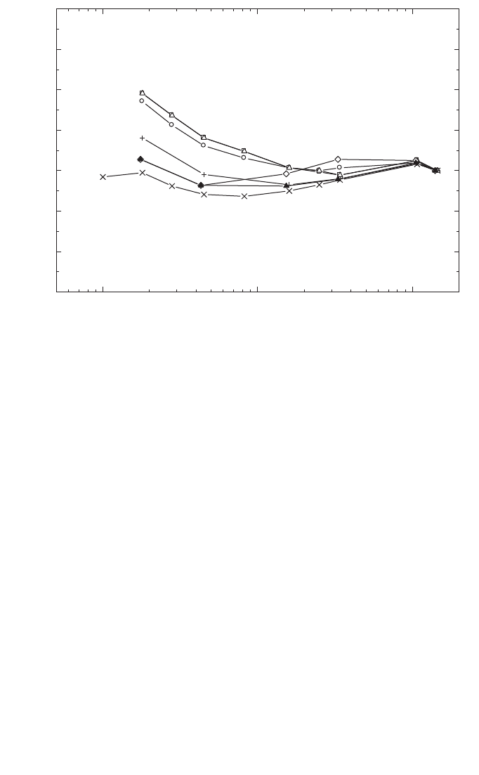
9.2. DOSIMETRY EQUIPMENT
9.2.1. Ionization chambers
The recommendations regarding ionization chambers given in Section 4.2.1
should be followed. Only cylindrical ionization chambers with a cavity volume in the
range 0.1–1.0 cm
3
are recommended for reference dosimetry in medium energy X ray
beams.
The reference point of a cylindrical chamber for the purpose of calibration at
the standards laboratory and for measurements under reference conditions in the user
beam is taken to be on the chamber axis at the centre of the cavity volume. This point
is positioned at a reference depth of 2 g/cm
2
in the water phantom.
Within a given chamber type, chamber to chamber variations in energy
response can be significant and, as for low energy X rays, each individual dosimeter
should be calibrated at a range of beam qualities suitable to allow interpolation to
the clinical beam qualities (see Fig. 11). It is not recommended that a generic set of
k
Q,Q
o
values for a particular type of chamber be used. The chamber should be
calibrated at the same SSD and field size as will be used for reference dosimetry in
the clinic.
123
0.1 1 10
0.94
0.96
0.98
1.00
1.02
1.04
1.06
1.08
70 kV
137
Cs
280250200150140120100
60
Co
k
Q
HVL (mm Cu)
FIG. 11. Chamber to chamber variation in k
Q
for seven ionization chambers, all of the type
M23331. The values are normalized at
60
Co (data measured at PTB).
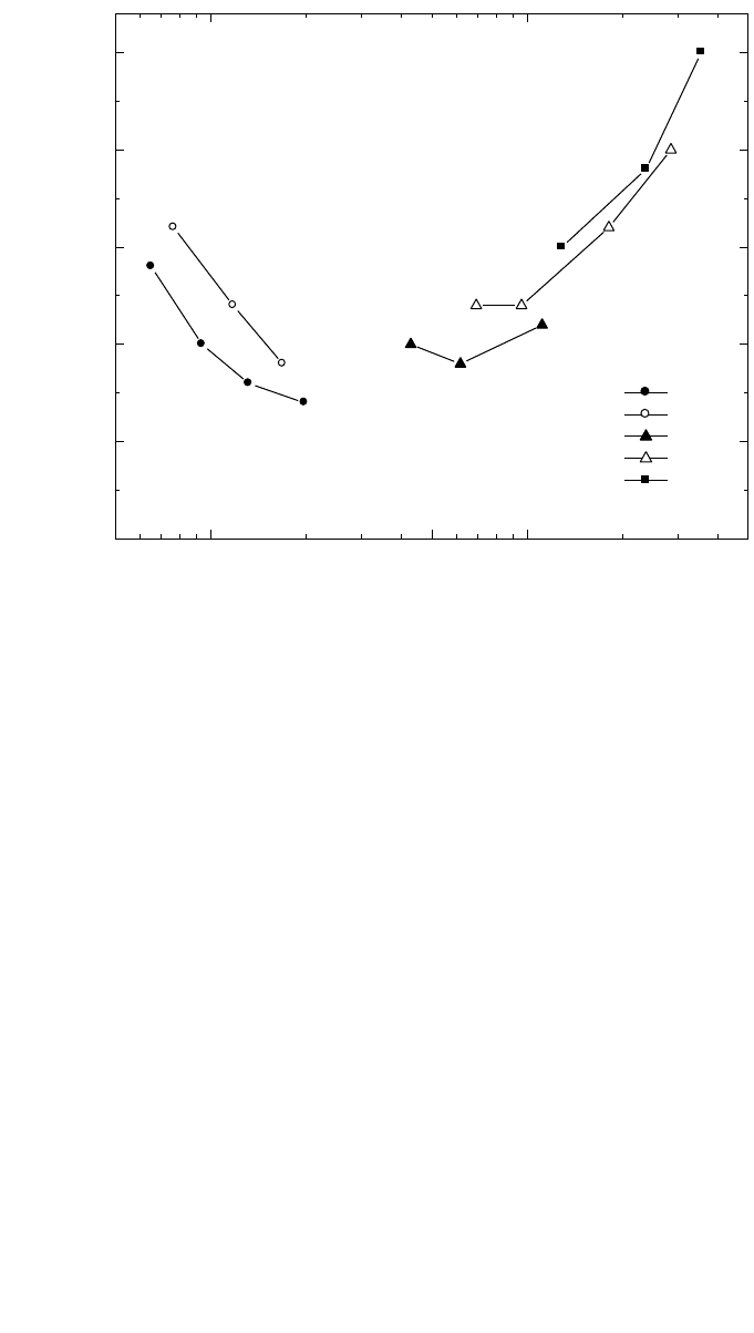
9.2.2. Phantoms and chamber sleeves
The recommendations regarding phantoms and chamber sleeves given in
Sections 4.2.3 and 4.2.4 should be followed. Water is recommended as the reference
medium for measurements of absorbed dose with medium energy X ray beams. The
phantom should extend to at least 5 cm beyond all four sides of the largest field size
employed at the depth of measurement. There should also be a margin of at least
10 g/cm
2
beyond the maximum depth of measurement.
In horizontal beams, the window of the phantom should be made of plastic and
of thickness t
win
between 0.2 cm and 0.5 cm. The water equivalent thickness (in
g/cm
2
) of the phantom window should be taken into account when evaluating the
depth at which the chamber is to be positioned; the thickness is calculated as the
product t
win
ρ
pl
where
ρ
pl
is the mass density of the plastic (in g/cm
3
). For commonly
124
FIG. 12. Calibration factor in terms of absorbed dose to water for an NE 2571 chamber as a
function of kV and HVL. These are derived from air kerma calibration factors measured at
NRL and converted to absorbed dose using factors given in Ref. [99]
.
0.05 0.1 0.5 1 5
N
D,w,Q
(Gy/nC
1
)
HVL (mm Cu)
0.0425
0.0430
0.0435
0.0440
0.0445
0.0450
N
D,w,Q
for an NE 2571 chamber
100 kV
120 kV
140 kV
200 kV
250 kV

used plastics PMMA and clear polystyrene, the nominal values
ρ
PMMA
= 1.19 g/cm
3
and
ρ
polystyrene
= 1.06 g/cm
3
[64] may be used for the calculation of the water equiv-
alent thickness of the window.
For non-waterproof chambers a waterproofing sleeve should be used, made of
PMMA, and preferably not thicker than 1.0 mm. The air gap between the chamber
wall and the waterproofing sleeve should be sufficient (0.1–0.3 mm) to allow the air
pressure in the chamber to equilibrate. The same waterproofing sleeve that was used
for calibration of the user’s ionization chamber should also be used for reference
dosimetry. If it is not possible to use the same waterproofing sleeve that was used
during calibration at the standardizing laboratory, then another sleeve of the same
material and of similar thickness should be used.
9.3. BEAM QUALITY SPECIFICATION
9.3.1. Choice of beam quality index
It has long been known that it is desirable to use more than one beam quality
parameter to characterize a kilovoltage X ray spectrum for dosimetry [98, 99]. The
usual quantities used are the kilovoltage generating potential (kV) and the HVL.
However, it is often not possible to match both the kV and HVL of each clinical beam
with the beams of the standards laboratory. Therefore the primary beam quality index
has traditionally been the HVL, and this is the beam quality index used in this Code
of Practice.
40
Up until now there are insufficient experimental data available to know how
N
D,w,Q
o
for a medium energy X ray chamber varies independently with HVL and
generating potential. However, some indication can be gained from Fig. 12 which
shows a plot of N
D,w,Q
for an NE 2571 chamber as a function of HVL and kV for a
range of typical therapy beam qualities. These values have been obtained from N
K,Q
(air kerma calibration factor) data using conversion factors given by Seuntjens [99].
125
40
Other beam quality specifiers were proposed by the ICRU in Refs [98, 99], including
a two point specification in terms of the so called ‘fall-off’ ratio. A recent proposal for using
the ratio of absorbed doses at 2 cm and 5 cm depths in water [102] is promising but needs fur-
ther investigation. This ratio is likely to be related to the mean X ray energy at the measure-
ment depth in the phantom, which is potentially a better beam quality specifier than the HVL,
which is measured in air. As noted in Section 8, the HVL is based on air kerma measurements
and requires a knowledge of the response of the dosimeter to air kerma. The development of a
new quality index for kV X rays based on the quantity absorbed dose to water, that is more
appropriate for this Code of Practice, would be welcomed.

126
The data suggest that the variation in N
D,w,Q
arising from using HVL only as the beam
quality index could be of the order of 1%. A conservative figure of 1.0% is therefore
taken as the resulting Type B standard uncertainty (see Appendix IV.3).
It is of course preferable, where possible, to have the dosimeter calibrated at the
same combinations of kV and HVL as those of the user clinical beams. But, if this is
not possible, calibration data should be obtained for beams with lesser and greater
HVLs and the desired values derived by interpolation (see worksheet).
9.3.2. Measurement of beam quality
In medium energy X ray beams, both aluminium and copper are used to deter-
mine the HVL. The HVL is defined as the thickness of an absorber which reduces the
air kerma rate of a narrow X ray beam at a reference point distant from the absorbing
layer to 50% compared with the air kerma rate for a non-attenuated beam.
The ideal arrangement is to place at about half the distance between the X ray
target and the chamber a collimating aperture that reduces the field size to just enough
to encompass the whole of the chamber. There should be no other scattering material
in the beam up to 1 m behind the chamber. The filters added for the HVL measure-
ment are placed close to the aperture in combinations of thickness which span the
HVL thickness to be determined. The thickness that reduces the air kerma rate to one
half is obtained by interpolation.
Strictly, it is the ionization current or the integrated charge per exposure time
that is measured, not the air kerma rate. This distinction is particularly relevant for
lightly filtered beams. A chamber with an energy response that varies less than 2%
over the quality range measured should be used.
41
A monitor chamber should be used to prevent misleading results due to the
variation in X ray output. Care must be taken so that the response of the monitor
chamber is not affected by increasing scatter as more filters are placed in the path of
the beam. If a monitor chamber is not available, the effects of output variation can be
minimized by randomizing the measurement sequence and measuring the air kerma
rate without additional filters both at the beginning and at the end.
The purity of aluminium or copper used for HVL measurements should be
99.9%. For further guidance on HVL determination see Refs [33, 71, 98, 100].
41
HVL measurement errors of up to 10% can result using a Farmer type chamber in a
lightly filtered 100 kV beam. If the chamber energy response varies by more than 2% over the
quality range, then each measurement must be converted to an air kerma measurement using
an air kerma calibration factor appropriate for each filtered or unfiltered beam. This is an iter-
ative process because the calibration factor itself is determined by the HVL.
9.4. DETERMINATION OF ABSORBED DOSE TO WATER
9.4.1. Reference conditions
The reference conditions for the determination of absorbed dose to water are
given in Table 27.
9.4.2. Determination of absorbed dose under reference conditions
The general formalism is given in Section 3. The absorbed dose to water at the
reference depth z
ref
in water, in a medium energy X ray beam of quality Q and in the
absence of the chamber, is given by
D
w,Q
= M
Q
N
D,w,Q
o
k
Q,Q
o
(38)
where M
Q
is the reading of the dosimeter with the reference point of the chamber
positioned at z
ref
in accordance with the reference conditions given in Table 27 and
corrected for the influence quantities temperature and pressure, polarity, and
electrometer calibration, as described in the worksheet (see also Section 4.4.3). The
correction for polarity is likely to be negligible. However, it should be checked at least
once, and there is provision for this in the worksheet. Alternatively, if the same
polarity that was used for calibration is always used for clinical measurements the
effect will cancel. The ionic recombination is negligible when the absorbed dose rate
is less than a few grays per minute (see Ref. [101]). N
D,w,Q
o
is the calibration factor
in terms of absorbed dose to water for the dosimeter at the reference quality Q
o
, and
k
Q,Q
o
is a chamber specific factor which corrects for differences between the
reference beam quality Q
o
and the actual beam quality being used, Q. Note also that
the correction for timer error may be significant. It is not a multiplicative correction,
and is therefore treated separately in the worksheet.
9.5. VALUES FOR k
Q,Q
o
The Bragg–Gray theory cannot be applied to ionization chambers in medium
energy X rays [103] and therefore the values for k
Q,Q
o
must be obtained directly from
measurements. Generic values, measured for a particular chamber type, should not be
used because of large chamber to chamber variations in k
Q,Q
o
with HVL (see Fig. 11).
The calibration data for the dosimeter should ideally be presented as a single
calibration factor N
D,w,Q
o
determined in a reference beam of quality Q
o
and one or
more measured factors k
Q,Q
o
corresponding to the other calibration qualities Q.
However, if the calibration data are in the form of a set of calibration factors N
D,w,Q
127

128
then one of the qualities should be chosen as the reference beam quality Q
o
. If the
dosimeter has also been calibrated in a
60
Co beam, this should be taken as the refer-
ence quality. But if the calibrations have been done in medium energy X rays only,
then one of the qualities should be chosen as the reference beam quality Q
o
.
42
The
corresponding calibration factor becomes N
D,w,Q
o
and the other calibration factors
N
D,w,Q
are expressed in terms of k
Q,Q
o
using the relation
(39)
D,w,Q
Q,Q
o
D,w,Q
o
N
k=
N
42
The choice here is not critical; the quality corresponding to the N
D,w,Q
factor with the
smallest uncertainty is appropriate, otherwise a quality close to the middle of the range.
TABLE 27. REFERENCE CONDITIONS FOR THE DETERMINATION OF
ABSORBED DOSE IN MEDIUM ENERGY X RAY BEAMS
Influence quantity Reference value or reference characteristics
Phantom material Water
Chamber type Cylindrical
Measurement depth z
ref
a
2 g/cm
2
Reference point of the chamber On the central axis at the centre of the cavity volume
Position of the reference point of At the measurement depth z
ref
the chamber
SSD Usual treatment distance
b
Field size 10 cm × 10 cm, or as determined by a reference
applicator
c
a
z
ref
is the reference depth in the phantom at which the reference point (see Section 9.2.1) of
the chamber is positioned.
b
If applicators of different SSD are used, then the one with the greatest SSD should be chosen
as the reference applicator.
c
When the X ray machine has an adjustable rectangular collimator, a 10 cm × 10 cm field
should be set. Otherwise, if the field is defined by fixed applicators, a reference applicator of
comparable size should be chosen.

129
If the quality of the user beam does not match any of the calibration qualities, the
value for k
Q,Q
o
to be used in Eq. (38) can be interpolated (see worksheet).
A chamber calibrated in a series of beam qualities may be subsequently recali-
brated at only the reference quality Q
o
. In this case, the new value for N
D,w,Q
o
should
be used with the values of k
Q,Q
o
previously measured. However, because of the
particular susceptibility of ionization chambers to change in energy response to
medium energy X rays, it is preferable that chambers are recalibrated at all qualities
each time. In particular, if N
D,w,Q
o
changes by an amount more than the uncertainty
stated for the calibration, or there have been any repairs to the chamber, then the
dosimeter should be recalibrated at all qualities.
9.6. MEASUREMENTS UNDER NON-REFERENCE CONDITIONS
9.6.1. Central axis depth dose distributions
A measurement under reference conditions prescribed in this Code of Practice
provides absorbed dose at the depth of 2 g/cm
2
in water. In order to relate this
measurement to the dose at other depths it is usually necessary to obtain the central
axis depth dose distribution. An estimate of the depth dose distribution may be
obtained from the literature [81]. However, it is unlikely that the published data will
match the exact kV and HVL of the clinical beam. Therefore, it is recommended that
the depth dose distributions be measured for each clinical beam.
In spite of kilovoltage X rays having been used in radiotherapy for some
decades, the methods of relative dosimetry have not been extensively researched.
According to Seuntjens and Verhaegan [104], a Farmer type cylindrical chamber
that is suitable for reference dosimetry should have a response in a phantom which
is reasonably independent of depth and field size. However, a chamber of this type
cannot be reliably used at depths in a phantom of less than about 0.5 cm. Depending
on the field size and beam energy, there may be a significant variation in the
absorbed dose in the first few millimetres of the depth dose distribution (see
Fig. 13).
It is possible to measure the depth dose distribution using a small ionization
chamber in a scanning tank, as used for relative dosimetry in high energy electron and
photon beams, or using a plane-parallel chamber of the type used for high energy
electron dosimetry [105]. This has the advantage of allowing measurements at depths
of less than 0.5 cm. However, these chamber types are not designed for use with kV
X rays and so the relationship between the depth ionization distribution and the depth
dose distribution (at depths greater than 0.5 cm) must be determined by comparison
with a Farmer type cylindrical chamber at a number of suitable depths. (The depth of
measurement of a cylindrical chamber in a phantom is taken to be the depth of the
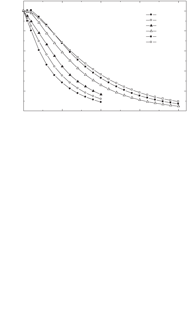
130
central axis of the chamber.) In most cases, differences between the two chamber
types are likely to be no more than a few per cent [100, 106]. Further assurance of the
accuracy of a particular chamber type can be gained by comparing with published
data [81], at least for beams for which these data are available.
Because of the overlap in the ranges of low energy and medium energy X rays,
the method of depth dose measurement using a plastic phantom as described in Section
8.6.1 may be used below 100 kV and 3 mm of aluminium HVL. It may be possible to
use the method at higher kV or HVL, but only a plastic that has been shown to give
measurements that agree within a few per cent with measurements in a water phantom
should be used. When making measurements near the surface, there must always be
sufficient material thickness to ensure full buildup of secondary electrons. The total
thickness required can be estimated from the csda range of the maximum energy
electrons in the material used (see Table 24 for 80–100 kV or Ref. [64]).
Some detectors that are used routinely for scanning high energy beams
(photons, electrons, etc.) are not suitable for use in medium energy X rays because of
excessive variation in response with beam quality at kilovoltage energies. Film
FIG. 13. Depth dose data for medium energy X rays. Data taken from Ref. [81]. Beam details:
2, 4 and 8 mm Al, 10 cm diameter, 20 cm SSD; 0.5, 1, and 3 mm Cu, 10 cm
×
10 cm, 50 cm
SSD.
0 5 10 15 20
0
20
40
60
80
100
HVL
2 mm Al
4 mm Al
8 mm Al
0.5 mm Cu
1 mm Cu
3 mm Cu
PDD
Depth in water (cm)

131
dosimetry and semiconductor diodes are, for this reason, not suitable. Some TLD
materials are suitable, but the energy response must be checked against an ionization
chamber before use.
9.6.2. Output factors
For clinical applications, output factors are required for all combinations of
SSD and field size used for radiotherapy treatment. The output factor for medium
energy X rays is the ratio of the absorbed dose at the surface of a water phantom for
a given SSD and field size to the absorbed dose measured under reference conditions
(reference conditions are given in Table 27). It is generally not possible to make reli-
able measurements directly at the surface of a phantom since there must be sufficient
depth to provide full buildup of secondary electrons. The method recommended in
this Code of Practice to obtain the output factor for each combination of SSD and
field size is to measure the absorbed dose to water at the depth of 2 g/cm
2
relative to
the absorbed dose measured under reference conditions for that beam quality, and
then to obtain the absorbed dose at the surface by extrapolation using a depth dose
distribution measured as described in Section 9.6.1.
9.7. ESTIMATED UNCERTAINTY IN THE DETERMINATION OF
ABSORBED DOSE TO WATER UNDER REFERENCE CONDITIONS
There is to date very little practical experience in standards of absorbed dose for
medium energy X rays. The uncertainty in N
D,w,Q
o
determined directly from a primary
standard is taken here to be 1%. Alternatively, if the absorbed dose to water is derived
from a standard of air kerma, the uncertainty in the determination of N
D,w,Q
is
estimated as 3%. In the latter case, the uncertainty of N
D,w,Q
o
then dominates the
overall uncertainty.
The X ray output from some machines depends on line voltage, tube tempera-
ture and operator control of tube current and voltage. This uncertainty should be
separately estimated by the user from the standard deviation of a set of at least five
exposures of typical treatment length. It is not included in this analysis.
Because the dose gradient from beams at the lower end of the energy range may
be as large as 1% per millimetre, there may be difficulty in achieving a depth
positioning reproducibility of better than 1%, so this uncertainty is assigned to the
establishment of reference conditions.
For medium energy X ray dosimetry, the values for k
Q,Q
o
are derived directly
from the calibration factors N
D,w,Q
. If the value of N
D,w,Q
o
used in Eq. (38) is the
same as that used in Eq. (39), then the uncertainty in the product k
Q,Q
o
N
D,w,Q
o
is
just the uncertainty in N
D,w,Q
together with an additional 1.0% to account for the

132
uncertainty of matching the calibration and user beams on the basis of HVL.
However, if the N
D,w,Q
o
used in Eq. (38) is different because it has been obtained
from a subsequent calibration of the dosimeter, then the uncertainty in k
Q,Q
o
is
increased because of the lack of correlation between the new N
D,w,Q
o
and that used
to calculate the k
Q,Q
o
. This results in an increase in the combined standard uncer-
tainty of D
w,Q
of up to 0.5%.
The uncertainties are summarized in Table 28.
TABLE 28. ESTIMATED RELATIVE STANDARD UNCERTAINTY
a
OF D
w,Q
AT
THE REFERENCE DEPTH IN WATER FOR A MEDIUM ENERGY X RAY
BEAM
Physical quantity or procedure Relative standard uncertainty (%)
Step 1: Standards laboratory SSDL SSDL PSDL PSDL
N
D,w,Q
o
or N
K
calibration of secondary standard 1.0 0.5
at PSDL
Long term stability of secondary standard 0.1 0.1
N
D,w,Q
o
calibration of the user dosimeter at
the standards lab
Absorbed dose standard 0.5 1.0
Derived from air kerma standard 3.0 3.0
Combined uncertainty in step 1: 1.2 3.0 1.0 3.0
Step 2: User X ray beam
Long term stability of user dosimeter 0.3
Establishment of reference conditions 1.0
Dosimeter reading M
Q
relative to timer or 0.1
beam monitor
Correction for influence quantities k
i
0.8
Beam quality correction, k
Q,Q
o
1.0
Combined uncertainty in step 2 1.6.
Combined standard uncertainty 2.0 3.4 1.9 3.0
of D
w,Q
(steps 1 + 2)
a
See the ISO Guide for the expression of uncertainty [32], or Appendix IV. The estimates given
in the table should be considered typical values; these may vary depending on the uncertainty
quoted by standards laboratories for calibration factors and on the experimental uncertainty
at the user’s institution.

133
9.8. WORKSHEET
Determination of the absorbed dose to water in a medium energy X ray beam
User: Date:
1. Radiation treatment unit and reference conditions for D
w,Q
determination
X ray machine: Nominal tube potential: kV
Nominal tube current:
mA Beam quality Q (HVL):
mm
❏ Al ❏ Cu
Reference phantom: water Reference depth: 2 g/cm
2
Reference field size:
cm × cm Reference SSD: cm
2. Ionization chamber and electrometer
Ionization chamber model: Serial No.:
Chamber wall material:
thickness = g/cm
2
Waterproof sleeve material: thickness = g/cm
2
Phantom window material: thickness = g/cm
2
Absorbed dose to water calibration factor N
D,w,Q
o
=
❏ Gy/nC ❏ Gy/rdg
Reference beam quality, Q
o
(HVL): mm ❏ Al ❏ Cu
Reference conditions for calibration P
o
: kPa T
o
: °C Rel. humidity: %
Polarizing potential V:
V Calibration polarity: ❏ +ve ❏ –ve ❏ corrected for polarity
User polarity: ❏ +ve ❏ –ve
effect
Calibration laboratory:
Date:
Electrometer model: Serial No.:
Calibrated separately from chamber: ❏ Yes ❏ No Rating setting:
If yes, calibration laboratory: Date:
3. Dosimeter reading
a
and correction for influence quantities
Uncorrected dosimeter reading at V and user polarity: ❏ nC ❏ rdg
Corresponding time:
min
Ratio of dosimeter reading and time
b
: M = ❏ nC/min ❏ rdg/min
(i) Pressure P: ________ kPa Temperature T: _______ °C Rel. humidity (if known): ____ %
(ii) Electrometer calibration factor
c
k
elec
: ❏ nC/rdg ❏ dimensionless k
elec
=
(iii) Polarity correction
d
rdg at +V: M
+
= rdg at –V : M
–
=
=
k
MM
M
pol
=
+
+-
2
k
T
T
P
P
TP
o
o
=
+
+
=
(. )
(. )
273 2
273 2

134
Corrected dosimeter reading at the voltage V:
M
Q
= M k
TP
k
elec
k
pol
= ❏ nC/min ❏ rdg/min
4. Absorbed dose rate to water at the reference depth, z
ref
Beam quality correction factor for user quality Q: k
Q,Q
o
=
at Q
o
(HVL) = mm ❏ Al ❏ Cu
Calibration laboratory:
Date:
or Beam quality correction factor interpolated:
(k
Q,Q
o
)
1
= at HVL
1
= mm ❏ Al ❏ Cu Date:
(k
Q,Q
o
)
2
= at HVL
2
= mm ❏ Al ❏ Cu Date:
Absorbed dose rate calibration at z
ref
:
D
w,Q
(z
ref
) = M
Q
N
D,w,Q
o
k
Q,Q
o
= Gy/min
5. Absorbed dose rate to water at the depth of dose maximum, z
max
Depth of dose maximum: z
max
= g/cm
2
Percentage depth dose at z
ref
for
cm × cm field size: PDD(z
ref
= 2 g/cm
2
) =
%
Absorbed dose rate calibration at z
max
:
D
w,Q
(z
max
) = 100 D
w,Q
(z
ref
)/PDD(z
ref
) = Gy/min
a
All readings should be checked for leakage and corrected if necessary.
b
The timer error should be taken into account. The correction at voltage V can be determined according to
M
A
is the integrated reading in a time t
A
M
A
= _________ t
A
= ________ min
M
B
is the integrated reading in n short exposures of time t
B
/n each (2 ≤ n ≤ 5)
M
B
= _________ t
B
= _________ min n = __
Timer error, min (the sign of τ must be taken into account)
❏ nC/min ❏ rdg/min
c
If the electrometer is not calibrated separately, set k
elec
= 1.
d
M in the denominator of k
pol
denotes reading at the user polarity. Preferably, each reading in the equation
should be the average of the ratios of M (or M
+
or M
–
) to the reading of an external monitor M
em
.
A
A
M
M= =
t+
t
BA AB
AB
Mt–Mt
==
nM –M
t
1
121
21
k
Q,Q Q,Q Q,Q Q,Q
oo o o
lnHVL – lnHVL
k =( ) + (k ) – (k ) = ____________
lnHVL – lnHVL
È˘
È˘
Í˙
Î˚
Î˚

135
10. CODE OF PRACTICE FOR PROTON BEAMS
10.1. GENERAL
This section provides a Code of Practice for reference dosimetry (beam
calibration) and recommendations for relative dosimetry in proton beams with
energies in the range from 50 MeV to 250 MeV. It is based upon a calibration factor
in terms of absorbed dose to water N
D,w,Q
o
for a dosimeter in a reference beam of
quality Q
o
.
43
At present, there are two main clinical applications for proton beams (see
Ref. [107]). Relatively low energy protons (less than 90 MeV) are employed in the
treatment of ocular tumours using field sizes smaller than 4 cm × 4 cm and high dose
rates. Higher energy protons (above 150 MeV) are used for the treatment of large or
deep seated tumours. For these applications, field sizes and dose rates similar to those
used with high energy photons are employed.
A typical depth dose distribution for a therapeutic proton beam is shown in
Fig. 14(a). This consists of a region where the dose increases slowly with depth,
called the ‘plateau’, and a region where the dose rises rapidly to a maximum, called
the ‘Bragg peak’. Clinical applications require a relatively uniform dose to be deliv-
ered to the volume to be treated, and for this purpose the proton beam has to be spread
out both laterally and in depth. This is obtained at a treatment depth by the superpo-
sition of Bragg peaks of different intensities and energies. The technique is called
‘beam modulation’ and creates a region of high dose uniformity referred to as the
‘spread-out Bragg peak’(SOBP) (see Fig. 14(b)). The width of the SOBP is normally
defined by the width of the 95% dose levels. Spreading out of a Bragg peak can be
achieved by different modulation techniques such as energy modulation [108] or
raster scanning or dynamic spot scanning [107, 109]; for the latter, the beam
modulation can be part of a more complex scanning technique in three dimensions.
Some treatments use the plateau region to treat the target, with the Bragg peak falling
beyond the distal side of the patient [110].
Clinical proton dosimetry to date has been based on different types of
dosimeters, such as calorimeters, ionization chambers, Faraday cups, track detec-
tors, activation systems and diodes [108,111,112]. Existing proton dosimetry proto-
cols [113–115] provide recommendations for ionization chamber dosimetry, based
43
As no primary standard of absorbed dose to water for proton beams is yet available,
60
Co gamma rays will be used as reference beam quality Q
o
for proton dosimetry (see
Section 10.5).
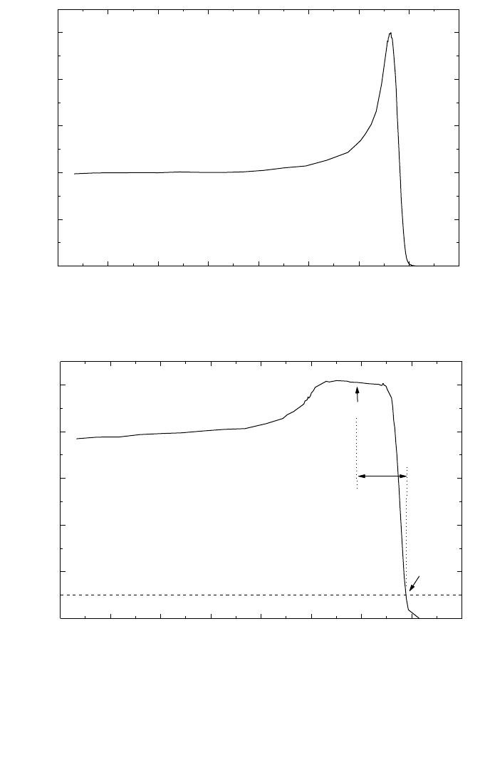
136
FIG. 14. (a) Percentage depth dose distribution for a 235 MeV proton beam, illustrating the
‘plateau’ region and the Bragg peak; (b) percentage depth dose distribution for a modulated
proton beam. Indicated on the figure are the reference depth z
ref
(middle of the SOBP), the
residual range at z
ref
used to specify the quality of the beam, R
res
, and the practical range R
p
.
0 5 10 15 20 25 30 35 40
20
40
60
80
100
235 MeV
Plateau region
Bragg peak
Relative dose
Depth in water (cm)
(a)
0 5 10 15 20 25 30 35 40
20
40
60
80
100
235 MeV
R
res
R
p
z
ref
SOBP
Relative dose
Depth in water (cm)
(b)

137
on in-air calibrations in a
60
Co beam in terms of exposure or air kerma. Reference
[116] discusses, in addition, the determination of absorbed dose in a proton beam
using ionization chambers calibrated in a
60
Co beam in terms of absorbed dose to
water; however, only a general description with little detail is provided.
10.2. DOSIMETRY EQUIPMENT
10.2.1. Ionization chambers
The recommendations regarding ionization chambers given in Section 4.2.1
should be followed. Both cylindrical and plane-parallel ionization chambers are
recommended for use as reference instruments for the calibration of clinical proton
beams. However, the combined standard uncertainty in D
w
for plane-parallel ioniza-
tion chambers will be slightly higher than for cylindrical chambers due to their higher
uncertainty for p
wall
in the
60
Co reference beam quality (see Table 32 and Appendix
II). For this reason, cylindrical ionization chambers are preferred for reference
dosimetry; their use is, however, limited to proton beams with qualities at the refer-
ence depth R
res
≥ 0.5 g/cm
2
. Graphite walled cylindrical chambers are preferable to
plastic walled chambers because of their better long term stability and smaller
chamber to chamber variations (see Section 4.2.1 and Fig. 2). The reference point for
these chambers is taken to be on the central axis of the chamber at the centre of the
cavity volume; this point is positioned at the reference depth in the phantom.
Plane-parallel chambers can be used for reference dosimetry in all proton
beams, but must be used for proton beams with qualities at the reference depth
R
res
< 0.5 g/cm
2
. For these chambers, the reference point is taken to be on the inner
surface of the entrance window, at the centre of the window; this point is positioned
at the point of interest in the phantom. The cavity diameter of the plane-parallel
ionization chamber or the cavity length of the cylindrical ionization chamber should
not be larger than approximately half the reference field size. Moreover, the outer
diameter for cylindrical ionization chambers should not be larger than half the
SOBP width.
For relative dosimetry, only plane-parallel ionization chambers are recom-
mended. The chamber types for which data are given in this Code of Practice are
listed in Table 31 of Section 10.5.
10.2.2. Phantoms and chamber sleeves
The recommendations regarding phantoms and chamber sleeves given in
Sections 4.2.3 and 4.2.4 should be followed. Water is recommended as the reference

138
medium for the determination of absorbed dose and for beam quality measurements
with proton beams. The phantom should extend to at least 5 cm beyond all four sides
of the field size employed at the depth of measurement and also extend to at least
5 g/cm
2
beyond the maximum depth of measurement.
In horizontal beams, the window of the phantom should be made of plastic and
of thickness t
win
between 0.2 and 0.5 cm. The water equivalent thickness (in g/cm
2
)
of the phantom window should be taken into account when evaluating the depth at
which the chamber is to be positioned; the thickness is calculated as the product
t
win
ρ
pl
where
ρ
pl
is the mass density of the plastic (in g/cm
3
). For the commonly used
plastics PMMA and clear polystyrene, the nominal values
ρ
PMMA
= 1.19 g/cm
3
and
ρ
polystyrene
= 1.06 g/cm
–3
[64] may be used for the calculation of the water equivalent
thickness of the window.
For non-waterproof chambers a waterproofing sleeve should be used, made of
PMMA, and preferably not thicker than 1.0 mm. The air gap between the chamber
wall and the waterproofing sleeve should be sufficient (0.1–0.3 mm) to allow the air
pressure in the chamber to equilibrate. The same waterproofing sleeve that was used
for calibration of the user’s ionization chamber should also be used for reference
dosimetry. If it is not possible to use the same waterproofing sleeve that was used
during calibration at the standardizing laboratory, then another sleeve of the same
material and of similar thickness should be used. Plane-parallel chambers, if not
inherently waterproof or supplied with a waterproof cover, must be used in a water-
proof enclosure, preferably of PMMA or a material that closely matches the chamber
walls; ideally, there should be no more than 1 mm of added material in front of and
behind the cavity volume.
Plastic phantoms should not be used for reference dosimetry in proton beams
since the required water to plastic fluence correction factors, h
pl
, are not known.
Information on the use of plastic phantoms for relative dosimetry is given in
Section 10.6.3.
10.3. BEAM QUALITY SPECIFICATION
10.3.1. Choice of beam quality index
In previous proton dosimetry protocols and recommendations [114–116], the
proton beam quality was specified by the effective energy, which is defined as the
energy of a monoenergetic proton beam having a range equal to the residual range
R
res
of the clinical proton beam (see definition below). This choice was justified by
the small energy dependence of water/air stopping-power ratios (see Fig. 21) and by
the fact that the effective energy is close to the maximum energy in the proton energy
spectrum at the reference depth (see reference conditions in Tables 29 and 30).

139
In this Code of Practice the residual range, R
res
, is chosen as the beam quality
index. This has the advantage of being easily measurable. Although this choice will
slightly underestimate the stopping-power ratios in the middle of the SOBP, this
effect is unlikely to exceed 0.3% [116, 117].
The residual range R
res
(in g/cm
2
) at a measurement depth z is defined as
R
res
= R
p
– z (40)
where z is the depth of measurement and R
p
is the practical range (both expressed in
g/cm
2
), which is defined [116] as the depth at which the absorbed dose beyond the
Bragg peak or SOBP falls to 10% of its maximum value (see Fig. 14(b)). Unlike other
radiation types covered in this Code of Practice, in the case of protons the quality Q
is not unique to a particular beam, but is also determined by the reference depth z
ref
chosen for measurement.
10.3.2. Measurement of beam quality
The residual range R
res
should be derived from a measured depth dose
distribution, obtained using the conditions given in Table 29. The preferred choice of
TABLE 29. REFERENCE CONDITIONS FOR THE DETERMINATION OF
PROTON BEAM QUALITY (R
res
)
Influence quantity Reference value or reference characteristics
Phantom material Water
Chamber type Cylindrical and plane parallel
Reference point of the chamber For plane-parallel chambers, on the inner surface of the
window at its centre. For cylindrical chambers, on the
central axis at the centre of the cavity volume
Position of the reference point For plane-parallel and cylindrical chambers, at the point
of the chamber of interest
SSD Clinical treatment distance
Field size at the phantom 10 cm × 10 cm
surface For small field applications (i.e. eye treatments),
10 cm × 10 cm or the largest field clinically available

140
detector for the measurement of central axis depth dose distributions is a plane-
parallel chamber. Additional information on the measurement of depth dose distribu-
tions is given in Section 10.6.
10.4. DETERMINATION OF ABSORBED DOSE TO WATER
10.4.1. Reference conditions
Reference conditions for the determination of absorbed dose to water in proton
beams are given in Table 30.
TABLE 30. REFERENCE CONDITIONS FOR THE DETERMINATION OF
ABSORBED DOSE IN PROTON BEAMS
Influence quantity Reference value or reference characteristics
Phantom material Water
Chamber type For R
res
≥ 0.5 g/cm
2
, cylindrical and plane parallel
For R
res
< 0.5 g/cm
2
, plane parallel
Measurement depth z
ref
Middle of the SOBP
a
Reference point of the chamber For plane-parallel chambers, on the inner surface
of the window at its centre
For cylindrical chambers, on the central axis at the centre
of the cavity volume
Position of the reference point For plane-parallel and cylindrical chambers, at the point
of the chamber of measurement depth z
ref
SSD Clinical treatment distance
Field size at the phantom 10 cm × 10 cm, or that used for normalization of the
surface output factors whichever is larger. For small field
applications (i.e. eye treatments), 10 cm × 10 cm or the
largest field clinically available
a
The reference depth can be chosen in the ‘plateau region’, at a depth of 3 g/cm
2
, for clinical
applications with a monoenergetic proton beam (e.g. for plateau irradiations).

141
10.4.2. Determination of absorbed dose under reference conditions
The general formalism for the determination of the absorbed dose to water is
given in Section 3. The absorbed dose to water at the reference depth z
ref
in water, in
a proton beam of quality Q and in the absence of the chamber, is given by
D
w,Q
= M
Q
N
D,w,Q
o
k
Q,Q
o
(41)
where M
Q
is the reading of the dosimeter with the reference point of the chamber
positioned at z
ref
in accordance with the reference conditions given in Table 30, cor-
rected for the influence quantities pressure and temperature, electrometer calibration,
polarity effect and ion recombination as described in the worksheet (see also Section
4.4.3). N
D,w,Q
o
is the calibration factor in terms of absorbed dose to water for the
dosimeter at the reference quality Q
o
and N
D,w,Q
o
is a chamber specific factor which
corrects for differences between the reference beam quality Q
o
and the actual quality
being used, Q.
10.5. VALUES FOR k
Q,Q
o
Ideally, the values for k
Q,Q
o
should be obtained by direct measurement of the
absorbed dose at the qualities Q and Q
o
, see Eq. (3), each measured under reference
conditions for the user’s ionization chamber used for proton dosimetry. However, at
present no primary standard of absorbed dose to water for proton beams is available.
Thus all values for k
Q,Q
o
given in this Code of Practice for proton beams are derived
by calculation and are based on
60
Co gamma radiation as the reference beam quality
Q
o
. The notation k
Q
denotes this exclusive use of
60
Co as the reference quality.
Values for k
Q
are calculated using Eq. (4). The data for the physical parameters
in this equation are discussed in Appendix II. Figure 15 shows calculated values for
k
Q
as a function of the beam quality index R
res
for some common cylindrical and
plane-parallel ionization chamber types. Table 31 gives calculated values for k
Q
as a
function of R
res
for cylindrical and plane-parallel ionization chambers. Values for k
Q
for non-tabulated qualities may be obtained by interpolation between tabulated
values.
10.6. MEASUREMENTS UNDER NON-REFERENCE CONDITIONS
Clinical dosimetry requires the measurement of central axis percentage depth
dose distributions, transverse beam profiles, output factors, etc. Such measurements
should be made for all possible combinations of energy, field size and SSD used for

142
TABLE 31. CALCULATED VALUES OF k
Q
FOR PROTON BEAMS, FOR VARIOUS CYLINDRICAL AND PLANE-PARALLEL
IONIZATION CHAMBERS AS A FUNCTION OF BEAM QUALITY R
res
Ionization chamber type
a
Beam quality R
res
(g/cm
2
)
0.25 0.5 1 1.5 2 2.5 3 3.5 4 4.5 5 7.5 10 15 20 30
Cylindrical chambers
Capintec PR-05P mini — 1.046 1.045 1.044 1.044 1.044 1.043 1.043 1.043 1.043 1.043 1.043 1.043 1.043 1.042 1.042
Capintec PR-05 mini — 1.046 1.045 1.044 1.044 1.044 1.043 1.043 1.043 1.043 1.043 1.043 1.043 1.043 1.042 1.042
Capintec PR-06C/G Farmer — 1.038 1.037 1.036 1.036 1.036 1.036 1.035 1.035 1.035 1.035 1.035 1.035 1.035 1.034 1.034
Exradin A2 Spokas — 1.057 1.055 1.054 1.054 1.054 1.054 1.054 1.054 1.054 1.054 1.053 1.053 1.053 1.053 1.052
Exradin T2 Spokas — 1.020 1.018 1.018 1.018 1.017 1.017 1.017 1.017 1.017 1.017 1.017 1.017 1.016 1.016 1.016
Exradin A1 mini Shonka — 1.045 1.043 1.043 1.042 1.042 1.042 1.042 1.042 1.042 1.042 1.042 1.042 1.041 1.041 1.041
Exradin T1 mini Shonka — 1.009 1.007 1.007 1.006 1.006 1.006 1.006 1.006 1.006 1.006 1.005 1.005 1.005 1.005 1.004
Exradin A12 Farmer — 1.043 1.042 1.041 1.041 1.041 1.041 1.040 1.040 1.040 1.040 1.040 1.040 1.040 1.039 1.039
Far West Tech. IC-18 — 1.007 1.006 1.005 1.005 1.005 1.004 1.004 1.004 1.004 1.004 1.004 1.004 1.003 1.003 1.003
FZH TK 01 — 1.032 1.031 1.030 1.030 1.030 1.030 1.029 1.029 1.029 1.029 1.029 1.029 1.029 1.028 1.028
Nuclear Assoc. 30-750 — 1.037 1.035 1.034 1.034 1.034 1.034 1.034 1.034 1.033 1.033 1.033 1.033 1.033 1.033 1.032
Nuclear Assoc. 30-749 — 1.041 1.039 1.039 1.038 1.038 1.038 1.038 1.038 1.038 1.038 1.037 1.037 1.037 1.037 1.036
Nuclear Assoc. 30-744 — 1.041 1.039 1.039 1.038 1.038 1.038 1.038 1.038 1.038 1.038 1.037 1.037 1.037 1.037 1.036
Nuclear Assoc. 30-716 — 1.041 1.039 1.039 1.038 1.038 1.038 1.038 1.038 1.038 1.038 1.037 1.037 1.037 1.037 1.036
Nuclear Assoc. 30-753
Farmer shortened — 1.041 1.040 1.039 1.039 1.038 1.038 1.038 1.038 1.038 1.038 1.038 1.038 1.037 1.037 1.037
Nuclear Assoc. 30-751 Farmer — 1.037 1.036 1.035 1.035 1.035 1.035 1.034 1.034 1.034 1.034 1.034 1.034 1.034 1.033 1.033
Nuclear Assoc 30-752 Farmer — 1.044 1.042 1.041 1.041 1.041 1.041 1.041 1.041 1.040 1.040 1.040 1.040 1.040 1.040 1.039

143
TABLE 31. (cont.)
NE 2515 — 1.033 1.032 1.031 1.031 1.031 1.031 1.030 1.030 1.030 1.030 1.030 1.030 1.030 1.029 1.029
NE 2515/3 — 1.043 1.041 1.041 1.040 1.040 1.040 1.040 1.040 1.040 1.040 1.039 1.039 1.039 1.039 1.038
NE 2577 — 1.043 1.041 1.041 1.040 1.040 1.040 1.040 1.040 1.040 1.040 1.039 1.039 1.039 1.039 1.038
NE 2505 Farmer — 1.033 1.032 1.031 1.031 1.031 1.031 1.030 1.030 1.030 1.030 1.030 1.030 1.030 1.029 1.029
NE 2505/A Farmer — 1.021 1.019 1.019 1.018 1.018 1.018 1.018 1.018 1.018 1.018 1.018 1.017 1.017 1.017 1.016
NE 2505/3, 3A Farmer — 1.043 1.041 1.041 1.040 1.040 1.040 1.040 1.040 1.040 1.040 1.039 1.039 1.039 1.039 1.038
NE 2505/3, 3B Farmer — 1.025 1.023 1.023 1.022 1.022 1.022 1.022 1.022 1.022 1.022 1.021 1.021 1.021 1.021 1.020
NE 2571 Farmer — 1.043 1.041 1.041 1.040 1.040 1.040 1.040 1.040 1.040 1.040 1.039 1.039 1.039 1.039 1.038
NE 2581 Farmer — 1.020 1.018 1.017 1.017 1.017 1.017 1.017 1.017 1.016 1.016 1.016 1.016 1.016 1.016 1.015
NE 2561 / 2611 Sec. Std — 1.040 1.038 1.038 1.037 1.037 1.037 1.037 1.037 1.037 1.037 1.037 1.036 1.036 1.036 1.036
PTW 23323 micro — 1.027 1.025 1.025 1.025 1.024 1.024 1.024 1.024 1.024 1.024 1.024 1.024 1.023 1.023 1.023
PTW 23331 rigid — 1.037 1.035 1.034 1.034 1.034 1.034 1.034 1.033 1.033 1.033 1.033 1.033 1.033 1.033 1.032
PTW 23332 rigid — 1.031 1.029 1.028 1.028 1.028 1.028 1.028 1.027 1.027 1.027 1.027 1.027 1.027 1.027 1.026
PTW 23333 — 1.033 1.031 1.031 1.030 1.030 1.030 1.030 1.030 1.030 1.030 1.029 1.029 1.029 1.029 1.028
PTW 30001/30010 Farmer — 1.033 1.031 1.031 1.030 1.030 1.030 1.030 1.030 1.030 1.030 1.029 1.029 1.029 1.029 1.028
PTW 30002/30011 Farmer — 1.036 1.035 1.034 1.034 1.034 1.034 1.033 1.033 1.033 1.033 1.033 1.033 1.033 1.032 1.032
PTW 30004/30012 Farmer — 1.044 1.042 1.041 1.041 1.041 1.041 1.041 1.041 1.041 1.040 1.040 1.040 1.040 1.040 1.039
PTW 30006/30013 Farmer — 1.033 1.032 1.031 1.031 1.031 1.030 1.030 1.030 1.030 1.030 1.030 1.030 1.029 1.029 1.029
PTW 31002 flexible — 1.032 1.030 1.029 1.029 1.029 1.029 1.029 1.029 1.029 1.029 1.028 1.028 1.028 1.028 1.027
PTW 31003 flexible — 1.032 1.030 1.029 1.029 1.029 1.029 1.029 1.029 1.029 1.029 1.028 1.028 1.028 1.028 1.027
SNC 100730 Farmer — 1.035 1.033 1.032 1.032 1.032 1.032 1.032 1.032 1.032 1.031 1.031 1.031 1.031 1.031 1.030
SNC 100740 Farmer — 1.046 1.044 1.044 1.043 1.043 1.043 1.043 1.043 1.043 1.043 1.043 1.042 1.042 1.042 1.042
Victoreen Radocon III 550 — 1.031 1.030 1.029 1.029 1.028 1.028 1.028 1.028 1.028 1.028 1.028 1.028 1.027 1.027 1.027
Victoreen Radocon II 555 — 1.014 1.012 1.012 1.011 1.011 1.011 1.011 1.011 1.011 1.011 1.011 1.010 1.010 1.010 1.010

144
TABLE 31. (cont.)
Victoreen 30-348 — 1.023 1.022 1.021 1.021 1.021 1.020 1.020 1.020 1.020 1.020 1.020 1.020 1.020 1.019 1.019
Victoreen 30—351 — 1.026 1.024 1.023 1.023 1.023 1.023 1.023 1.023 1.022 1.022 1.022 1.022 1.022 1.022 1.021
Victoreen 30-349 — 1.030 1.028 1.027 1.027 1.027 1.027 1.027 1.027 1.026 1.026 1.026 1.026 1.026 1.026 1.025
Victoreen 30-361 — 1.023 1.021 1.020 1.020 1.020 1.020 1.020 1.020 1.020 1.020 1.019 1.019 1.019 1.019 1.018
Scdx-Wellhöfer IC 05 — 1.041 1.039 1.039 1.038 1.038 1.038 1.038 1.038 1.038 1.038 1.037 1.037 1.037 1.037 1.036
Scdx-Wellhöfer IC 06 — 1.041 1.039 1.039 1.038 1.038 1.038 1.038 1.038 1.038 1.038 1.037 1.037 1.037 1.037 1.036
Scdx-Wellhöfer IC 10 — 1.041 1.039 1.039 1.038 1.038 1.038 1.038 1.038 1.038 1.038 1.037 1.037 1.037 1.037 1.036
Scdx-Wellhöfer IC 15 — 1.041 1.039 1.039 1.038 1.038 1.038 1.038 1.038 1.038 1.038 1.037 1.037 1.037 1.037 1.036
Scdx-Wellhöfer IC 25 — 1.041 1.039 1.039 1.038 1.038 1.038 1.038 1.038 1.038 1.038 1.037 1.037 1.037 1.037 1.036
Scdx-Wellhöfer IC 28
Farmer shortened — 1.041 1.040 1.039 1.039 1.038 1.038 1.038 1.038 1.038 1.038 1.038 1.038 1.037 1.037 1.037
Scdx-Wellhöfer IC 69 Farmer — 1.037 1.036 1.035 1.035 1.035 1.035 1.034 1.034 1.034 1.034 1.034 1.034 1.034 1.033 1.033
Scdx-Wellhöfer IC 70 Farmer — 1.043 1.042 1.041 1.041 1.040 1.040 1.040 1.040 1.040 1.040 1.040 1.040 1.039 1.039 1.039
Plane-parallel chambers
Attix RMI 449 0.995 0.992 0.990 0.989 0.989 0.989 0.989 0.989 0.989 0.989 0.989 0.988 0.988 0.988 0.988 0.987
Capintec PS-033 1.029 1.026 1.024 1.024 1.023 1.023 1.023 1.023 1.023 1.023 1.023 1.022 1.022 1.022 1.022 1.021
Exradin P11 1.000 0.997 0.995 0.994 0.994 0.994 0.994 0.994 0.994 0.994 0.993 0.993 0.993 0.993 0.993 0.992
Holt (Memorial) 1.014 1.010 1.009 1.008 1.008 1.008 1.008 1.008 1.007 1.007 1.007 1.007 1.007 1.007 1.007 1.006
NACP/Calcam 0.994 0.991 0.989 0.989 0.988 0.988 0.988 0.988 0.988 0.988 0.988 0.987 0.987 0.987 0.987 0.986
Markus 1.009 1.005 1.004 1.003 1.003 1.003 1.003 1.003 1.002 1.002 1.002 1.002 1.002 1.002 1.002 1.001
Roos 1.008 1.004 1.003 1.002 1.002 1.002 1.002 1.002 1.001 1.001 1.001 1.001 1.001 1.001 1.001 1.000
a
Some of the chambers listed in this table fail to meet some of the minimum requirements described in Section 4.2.1. However, they have been
included because of their current clinical use.
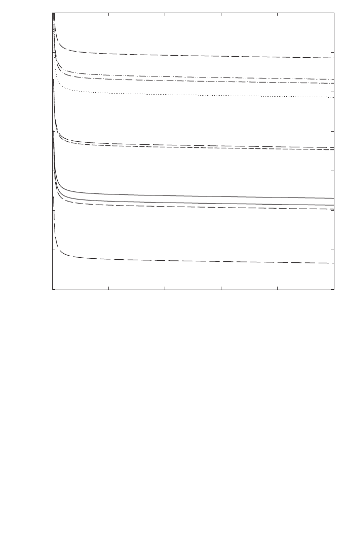
145
radiotherapy treatments. The recommendations given in Section 10.2 regarding
choices for ionization chambers and phantoms should be followed.
10.6.1. Central axis depth dose distributions
For measurements of depth dose distributions, the use of plane-parallel cham-
bers is recommended. The measured depth ionization distribution must be converted
to a depth dose distribution due to the depth dependence of the stopping-power ratio
FIG. 15. Calculated values of k
Q
for various cylindrical and plane-parallel ionization cham-
bers commonly used for reference dosimetry, as a function of proton beam quality Q (R
res
)
(data from Table 14).
Proton beam quality, R
res
(g/cm
2
)
0 5 10 15 20 25
k
Q
0.98
0.99
1.00
1.01
1.02
1.03
1.04
1.05
NACP
Markus
NE 2571
Wellhöfer IC 69
PTW 30002
PTW 30001
NE 2581
Exradin T2
FWT IC-18
Roos
Markus
FWT IC 18

146
s
w,air
, particularly in the low energy region. This is achieved by multiplying the
measured ionization charge or current at each depth z by the stopping-power ratio
s
w,air
and the perturbation factor at that depth. Values for s
w,air
as a function of R
res
can
be calculated from Eq. (73) given in Appendix II. Perturbation factors are assumed to
have a value of unity (see Appendix II). The influence of ion recombination and
polarity effects on the depth ionization distribution should be investigated and taken
into account if there is a variation with depth.
If the field size for which measurements are to be performed is smaller than
twice the diameter of the cavity of the plane-parallel chamber, then a detector with a
better spatial resolution (e.g. mini-chamber, diode or diamond) is recommended. The
resulting distribution must also be converted using the appropriate stopping-power
ratios (e.g. water to air, water to silicon or water to graphite). For the latter, the
necessary stopping-power values can be found in Ref. [118]. The suitability of such
detectors for depth dose measurements should be verified by test comparisons with a
plane-parallel chamber at a larger field size.
For clinical proton beams produced by dynamic beam delivery systems (i.e.
spot scanning), measurement times should be long enough compared to the scanning
cycle of the field in order to yield reproducible readings.
10.6.2. Output factors
The output factor may be determined as the ratio of corrected dosimeter read-
ings at the reference depth z
ref
measured under a given set of non-reference conditions
relative to that measured under reference conditions (reference conditions are given
in Table 30). For a given proton beam, output factors should be measured for all non-
reference field sizes and SSDs used for patient treatments.
10.6.3. Use of plastic phantoms for relative dosimetry
The use of plastic phantoms is strongly discouraged as, in general, they are
responsible for discrepancies in the determination of absorbed dose. Plastic phantoms
should not be used for reference dosimetry in proton beams since the required water
to plastic fluence correction factors, h
pl
, are not known. Nevertheless, when accurate
chamber positioning in water is not possible or when no waterproof chamber is
available, their use is permitted for the measurement of depth dose distribution for
low energy proton beams (approximately below 100 MeV). In this case, the dosimeter
reading at each plastic depth should be scaled using the fluence scaling factor h
pl
. It
is assumed that h
pl
has constant value of unity at all depths.
The criteria determining the choice of plastic materials are discussed in
Section 4.2.3. The density of the plastic, ρ
pl
, should be measured for the batch of
plastic in use rather than using a nominal value for the plastic type. Each

147
measurement depth in plastic z
pl
(expressed in g/cm
2
) must also be scaled to give the
corresponding depth in water z
w
by
z
w
= z
pl
c
pl
g/cm
2
(z
pl
in g/cm
2
) (42)
where c
pl
is a depth scaling factor. For proton beams, c
pl
can be calculated, to a good
approximation, as the ratio of csda ranges (in g/cm
2
) [118] in water and in plastic. The
depth scaling factor c
pl
has a value of 0.974 for PMMA and 0.981 for clear
TABLE 32. ESTIMATED RELATIVE STANDARD UNCERTAINTY
a
OF D
w,Q
AT THE REFERENCE DEPTH IN WATER AND FOR A CLINICAL PROTON
BEAM, BASED ON A CHAMBER CALIBRATION IN
60
Co GAMMA
RADIATION
Physical quantity or procedure
Relative standard uncertainty (%)
User chamber type: Cylindrical Plane parallel
Step 1: Standards laboratory SSDL
b
SSDL
b
N
D,w
calibration of secondary standard at PSDL 0.5 0.5
Long term stability of secondary standard 0.1 0.1
N
D,w
calibration of the user dosimeter at the 0.4 0.4
standards laboratory
Combined uncertainty in step 1 0.6 0.6
Step 2: User proton beam
Long term stability of the user dosimeter 0.3 0.4
Establishment of reference conditions 0.4 0.4
Dosimeter reading M
Q
relative to beam monitor 0.6 0.6
Correction for influence quantities k
i
0.4 0.5
Beam quality correction, k
Q
1.7 2.0
Combined uncertainty in step 2 1.9 2.2
Combined standard uncertainty in D
w,Q
(steps 1 + 2) 2.0 2.3
a
See the ISO Guide for the expression of uncertainty [32], or Appendix IV. The estimates given
in the table should be considered typical values; these may vary depending on the uncertainty
quoted by standards laboratories for calibration factors and on the experimental uncertainty
at the user’s institution.
b
If the calibration of the user dosimeter is performed at a PSDL then the combined standard
uncertainty in step 1 is lower. The combined standard uncertainty in D
w
should be adjusted
accordingly.

148
polystyrene. The procedure given in Section 10.6.1 should be followed to generate
central axis depth dose distributions from the measure depth ionization distributions.
If a plastic phantom is used to measure the beam quality index, the measured
quantity is the residual range in the plastic, R
res,pl
. The residual range, R
res
, in water
is also obtained using the scaling Eq. (42).
10.7. ESTIMATED UNCERTAINTY IN THE DETERMINATION OF
ABSORBED DOSE TO WATER UNDER REFERENCE CONDITIONS
The uncertainties associated with the physical quantities and procedures
involved in the determination of the absorbed dose to water in the user proton beam
can be divided into two steps. Step 1 considers uncertainties up to the calibration of
the user chamber in terms of N
D,w
at a standards laboratory. Step 2 deals with the
subsequent calibration of the user proton beam using this chamber and includes the
uncerainty of k
Q
as well as that associated with measurements at the reference depth
in a water phantom. Estimates of the uncertainties in these two steps are given in
Table 32, yielding a combined standard uncerainty of 2% and 2.3% for the determi-
nation of the absorbed dose to water in a clinical proton beam with a cylindrical and
plane-parallel ionization chamber, respectively. Details on the uncertainty estimates
for the various physical parameters entering in the calculation of k
Q
are given in
Appendix II.

149
10.8. WORKSHEET
Determination of the absorbed dose to water in a proton beam
User: Date:
1. Radiation treatment unit and reference conditions for D
w,Q
determination
Proton therapy unit: Nominal energy: MeV
Nominal dose rate:
MU/min Practical range, R
p
: g/cm
2
Reference phantom: water Width of the SOBP: g/cm
2
Reference field size:
cm × cm Reference SSD: cm
Reference depth, z
ref
: g/cm
2
Beam quality, Q(R
res
): g/cm
2
2. Ionization chamber and electrometer
Ionization chamber model:
Serial No.: Type: ❏ cyl ❏ pp
Chamber wall/window material:
thickness = g/cm
2
Waterproof sleeve/cover material: thickness = g/cm
2
Phantom window material:
thickness = g/cm
2
Absorbed dose to water calibration factor N
D,w
=
❏ Gy/nC ❏ Gy/rdg
Reference conditions for calibration P
o
: kPa T
o
:
°
C Rel. humidity: %
Polarizing potential V
1
:
V Calibration polarity: ❏ +ve ❏ –ve ❏ corrected for polarity
User polarity: ❏ +ve ❏ –ve
effect
Calibration laboratory:
Date:
Electrometer model: Serial No.:
Calibrated separately from chamber: ❏ Yes ❏ No Range setting:
If yes, calibration laboratory: Date:
3. Dosimeter reading
a
and correction for influence quantities
Uncorrected dosimeter reading at V
1
and user polarity: ❏ nC ❏ rdg
Corresponding accelerator monitor units:
MU
Ratio of dosimeter reading and monitor units: M
1
= ❏ nC/MU ❏ rdg/MU
(i) Pressure P: __________ kPa Temperature T: _______ °C Rel. humidity (if known): ____ %
(ii) Electrometer calibration factor
b
k
elec
: ❏ nC/rdg ❏ dimensionless k
elec
=
(iii) Polarity correction
c
rdg at +V
1
: M
+
= rdg at –V
1
: M
–
=
=
k
MM
M
pol
=
+
+-
2
k
T
T
P
P
TP
o
o
=
+
+
=
(. )
(. )
273 2
273 2
150
(iv) Recombination correction (two voltage method)
Polarizing voltages: V
l
(normal) = ____________ V V
2
(reduced) = _______________ V
Readings
d
at each V: M
1
= ___________________ M
2
= _______________________
Voltage ratio V
1
/V
2
= __________________________ Ratio of readings M
1
/M
2
= ___________
Use Table 9 for a beam of type: ❏ pulsed ❏ pulsed-scanned
a
0
= ____________ a
1
= ____________ a
2
= ____________
_____________
e,f
Corrected dosimeter reading at the voltage V
1
:
M
Q
= M
1
k
TP
k
elec
k
pol
k
s
= ❏ nC/MU ❏ rdg/MU
4. Absorbed dose rate to water at the reference depth, z
ref
Beam quality correction factor for user quality Q: k
Q
=
taken from ❏ Table 31 ❏ Other, specify:
Absorbed dose calibration of monitor at z
ref
:
D
w,Q
(z
ref
) = M
Q
N
D,w,
k
Q
= Gy/MU
a
All readings should be checked for leakage and corrected if necessary.
b
If the electrometer is not calibrated separately, set k
elec
= 1.
c
M in the denominator of k
pol
denotes reading at the user polarity. Preferably, each reading in the equation
should be the average of the ratios of M (or M
+
or M
–
) to the reading of an external monitor M
em
.
It is assumed that the calibration laboratory has performed a polarity correction. Otherwise, k
pol
is deter-
mined according to:
rdg at +V
1
for quality Q
o
: M
+
= ___________ rdg at –V
1
for quality Q
o
: M
–
= ____________
d
Strictly, readings should be corrected for polarity effect (average with both polarities). Preferably, each
reading in the equation should be the average of the ratios of M
1
or M
2
to the reading of an external
monitor M
em
.
e
It is assumed that the calibration laboratory has performed a recombination correction. Otherwise, the
factor k
′
s
= k
s
/k
s,Q
o
should be used instead of k
s
. When Q
o
is
60
Co, k
s,Q
o
(at the calibration laboratory) will
normally be close to unity and the effect of not using this equation will be negligible in most cases.
f
Check that
12
12
1
1
1
s
MM–
k–
VV–
ª
()
()
pol
+–
+–
Q
Q
o
M+M M
k = = ___________
M+M M
È˘
Î˚
È˘
Î˚
kaa
M
M
a
M
M
s
=+
Ê
Ë
Á
ˆ
¯
˜
+
Ê
Ë
Á
ˆ
¯
˜
=
01
1
2
2
1
2
2
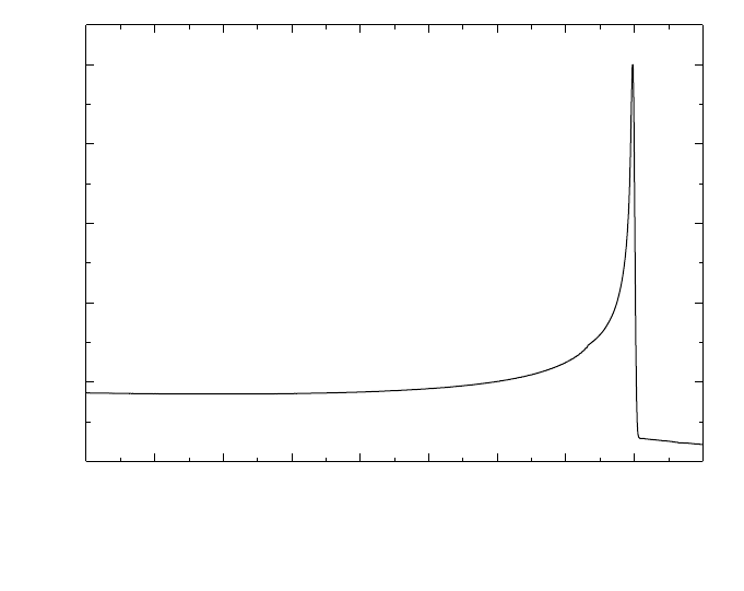
151
11. CODE OF PRACTICE FOR HEAVY ION BEAMS
11.1. GENERAL
This section provides a Code of Practice for reference dosimetry (beam
calibration) and recommendations for relative dosimetry in heavy ion beams. It is
based on a calibration factor in terms of absorbed dose to water of an ionization
chamber in a reference beam which, owing to the lack of primary standards for heavy
ions, is taken to be
60
Co gamma rays. The Code of Practice applies to heavy ion
beams with atomic numbers between 2(He) and 18(Ar) which have ranges of
2–30 g/cm
2
in water. For a carbon beam, this corresponds to an energy range of
100–450 MeV/u.
In the same way as for proton beams (see Section 10), the depth dose distribu-
tion of a monoenergetic heavy ion beam in water, shown in Fig. 16, has a sharp Bragg
peak near the region where primary particles stop. For clinical applications of heavy
ion beams, spread-out Bragg peaks (SOBP) are generated so that they include the
FIG. 16. Depth dose distribution of a monoenergetic 290 MeV/u carbon beam in water.
20
40
60
80
100
Relative dose
Depth in water (mm)
0 20 40 60 80 100 120 140 160 180
290 MeV/u carbon

152
complete target volume inside the SOBP. As opposed to most of the therapeutic
radiation beams (excluding neutrons), owing to the strong dependence of the biolog-
ical response on the energy of heavy ions in clinical applications it is common to use
a biological effective dose [119, 120] instead of a physical dose (absorbed dose to
water). The difference between the two kinds of distributions can be seen in
Figs 17(a) and 17(b), where the lack of uniformity of the physical dose distribution in
the SOBP is obvious. As is well known, the biological effective dose is defined as the
physical absorbed dose multiplied by the relative biological effectiveness (RBE) of
the beam for the tissue under consideration. In the case of heavy ions the RBE varies
with depth and with dose delivered to the tissue. The use of a biological effective dose
makes it possible to compare results obtained with conventional radiotherapy to those
using heavy ion radiotherapy.
In this Code of Practice, however, the dosimetry of heavy ions is restricted to
the determination of the physical dose using standards of absorbed dose to water
disseminated through an ionization chamber calibrated in terms of absorbed dose to
water, N
D,w,Q
o
. The reason for this limited approach is based on the feasibility of using
the same formalism and procedures for all the radiotherapy beams used throughout
the world, to achieve international consistency in dosimetry. The robustness of a
common framework for radiotherapy dosimetry will encourage correlated compar-
isons of the delivery of absorbed dose to patients, reducing the number of degrees of
freedom in comparing the outcome of a radiotherapy treatment. Biological studies
can then be made on the basis of uniform dosimetry procedures.
Heavy ion beams used in radiotherapy have a distinct physical characteristic for
radiation dosimetry compared to other therapeutic radiation beams [122]. In the case
of high energy protons, incident particles interact with target nuclei and produce low
energy protons or heavy ions. When heavy ions pass through beam modulating
devices or human tissues, they produce nuclei fragmented from the projectile and the
target nuclei. The nuclei produced by fragmentation have approximately the same
velocity as the incident heavy ions, and fragmented nuclei reach deeper regions than
those where the incident particles stop. Many kinds of atomic nuclei are present, all
with different energy distributions. This fragmentation of projectiles and targets
affects considerably the biological response to heavy-ion beams influencing the
dosimetry of heavy ions. Compared with the depth dose distribution of a proton beam
(see Fig. 14), Fig. 16 shows a tail at the distal end of the Bragg peak which is due to
the fragmentation of the incident particles.
Up to now, the only dosimetry recommendations available were those of the
protocol by the Association of American Physicists in Medicine Task Group 20 in
1984 [113]. The lack of a modern protocol for heavy ions has motivated recent inter-
comparisons of carbon beam dosimetry using different approaches [123, 124]. There
is thus a need for a new protocol in order to establish a global consistency in the deter-
mination of absorbed dose to water with heavy ions, common to dosimetry protocols
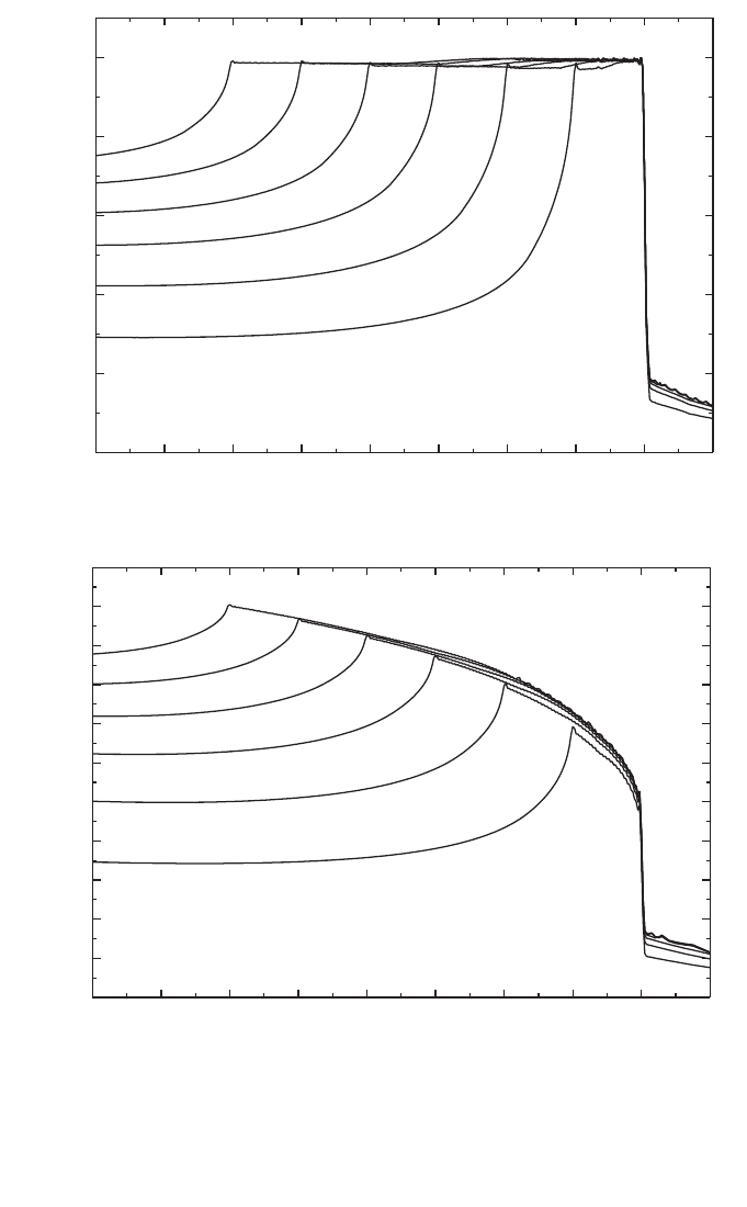
153
FIG. 17. (a) Biological dose distributions of therapeutic carbon beams of energy 290 MeV/u.
SOBPs of 20 to 120 mm width are designed to yield uniform biological effect in the peaks;
(b) physical dose distributions of the beam shown in (a) .
20
40
60
80
100
Depth in water (mm)
0 20 40 60 80 100 120 140 160 180
204060
80
100
120
SOBP width
Relative biological dose
(a)
20
40
60
80
100
Depth in water (mm)
0 20 40 60 80 100 120 140 160 180
Relative physical dose
10
30
50
70
90
110
20
40
60
80
100
120
SOBP width
(b)

154
for other radiotherapy beams. Absorbed dose in heavy ion beams can be measured
using an ionization chamber or a calorimeter. Fluence measurement methods can also
be applied for the determination of the absorbed dose of monoenergetic beams [113].
In this Code of Practice only the method based on ionometric measurements is
discussed.
For an accurate determination of absorbed dose from heavy ion beams using an
ionization chamber, it is desirable to know the energy spectra of the incident heavy
ion beam, the projectile fragments and also of the target fragmented nuclei. Very few
experimental and theoretical data on the spectral distribution of heavy ion beams are
available [125–127]. Thus, simplified values for the physical parameters required in
heavy ion dosimetry with ionization chambers will be adopted in this Code of
Practice.
11.2. DOSIMETRY EQUIPMENT
11.2.1. Ionization chambers
The recommendations regarding ionization chambers given in Section 4.2.1
should be followed. Cylindrical and plane-parallel ionization chambers are
recommended for use as reference instruments in clinical heavy ion beams. However,
the combined standard uncertainty on D
w,Q
for plane-parallel ionization chambers
will be slightly higher due to their higher uncertainty for p
wall
in the
60
Co reference
beam quality (see Table 35 and the discussion in Appendix II). For this reason,
cylindrical ionization chambers are preferred for reference dosimetry. However, their
use is limited to heavy ion beams with a SOBP width ≥2.0 g/cm
2
. Graphite walled
cylindrical chambers are preferred to plastic walled chambers because of their better
long term stability and smaller chamber to chamber variations (see Section 4.2.1 and
Fig. 2). The reference point for these chambers is taken to be on the central axis of
the chamber at the centre of the cavity volume. In the case of heavy ion beams, an
effective point of measurement of the chamber, P
eff
, should be used because the depth
dose distribution in the SOBP is not flat and the slope depends on the width of the
SOBP [123]. The reference point of the cylindrical chamber should be positioned a
distance 0.75 r
cyl
deeper than the point of interest in the phantom, where r
cyl
is the
inner radius of the chamber.
Plane-parallel chambers can be used for reference dosimetry in all heavy ion
beams, but must be used for heavy ion beams with a SOBP width <2.0 g/cm
2
. For
plane-parallel ionization chambers, the reference point is taken to be on the inner
surface of the entrance window, at the centre of the window. This point is positioned
at the point of interest in the phantom. The cavity diameter of the plane-parallel

155
ionization chamber or the cavity length of the cylindrical ionization chamber should
not be larger than approximately half the reference field size.
For relative dosimetry, only plane-parallel ionization chambers are recom-
mended. The chamber types for which data are given in this Code of Practice are
listed in Table 34 of Section 11.5.
11.2.2. Phantoms and chamber sleeves
The recommendations regarding phantoms and chamber sleeves given in
Sections 4.2.3 and 4.2.4 should be followed. Water is recommended as the reference
medium for measurements of absorbed dose in heavy ion beams. The phantom should
extend to at least 5 cm beyond all four sides of the field size employed at the depth
of measurement and also extend to at least 5 g/cm
2
beyond the maximum depth of
measurement.
In horizontal beams, the window of the phantom should be made of plastic and
of thickness t
win
between 0.2 and 0.5 cm. The water equivalent thickness (in g/cm
2
)
of the phantom window should be taken into account when evaluating the depth at
which the chamber is to be positioned; the thickness is calculated as the product
t
win
ρ
pl
where
ρ
pl
is the mass density of the plastic (in g/cm
3
). Efforts should be made
to obtain information about the density of plastic of which the phantom is made. For
the commonly used plastics PMMA and clear polystyrene, the nominal values
ρ
PMMA
= 1.19 g/cm
3
and
ρ
polystyrene
= 1.06 g/cm
3
[64] may be used for the calcula-
tion of the water equivalent thickness of the window.
For non-waterproof chambers a waterproofing sleeve should be used, made of
PMMA, and preferably not thicker than 1.0 mm. The air gap between the chamber
wall and the waterproofing sleeve should be sufficient (0.1–0.3 mm) to allow the air
pressure in the chamber to equilibrate. The same waterproofing sleeve that was used
for calibration of the user’s ionization chamber should also be used for reference
dosimetry. If it is not possible to use the same waterproofing sleeve that was used
during calibration at the standardizing laboratory, then another sleeve of the same
material and of similar thickness should be used. Plane-parallel chambers, if not
inherently waterproof or supplied with a waterproof cover, must be used in a water-
proof enclosure, preferably of PMMA or a material that closely matches the chamber
walls; ideally, there should be no more than 1 mm of added material in front of and
behind the cavity volume.
Plastic phantoms should not be used for reference dosimetry in heavy ion
beams since the required water to plastic fluence correction factors, h
pl
, are not
known. Moreover, the fluence of heavy ions including fragmented particles in a
plastic phantom will be different from that in a water phantom. However, plastic
phantoms can be used for routine quality assurance measurements, provided a
transfer factor between plastic and water has been established.

156
11.3. BEAM QUALITY SPECIFICATION
Very few experimental and theoretical data on the spectral distributions of
heavy ion beams are available. The current practice for characterizing a heavy ion
beam is to use the atomic number, mass number, energy of the incident heavy ion
beam, width of SOBP and range.
11.4. DETERMINATION OF ABSORBED DOSE TO WATER
11.4.1. Reference conditions
As shown in Fig. 17(b), the SOBP of a heavy ion depth dose distribution is not
flat, and the dose at the distal end of the SOBP is smaller than that at the proximal
part. The slope near the centre of a broad SOBP is rather small whereas that of a
narrow SOBP is steep. The reference depth for calibration should be taken at the
centre of the SOBP, at the centre of the target volume.
Reference conditions for the determination of absorbed dose to water are given
in Table 33.
TABLE 33. REFERENCE CONDITIONS FOR THE DETERMINATION OF
ABSORBED DOSE IN HEAVY ION BEAMS
Influence quantity Reference value or reference characteristics
Phantom material Water
Chamber type For SOBP width ≥2.0 g/cm
2
, cylindrical and plane-parallel
chambers
For SOBP width <2.0 g/cm
2
, plane-parallel chambers
Measurement depth z
ref
Middle of the SOBP
Reference point of For plane-parallel chambers, on the inner surface of the
the chamber window at its centre. For cylindrical chambers, on the central
axis at the centre of the cavity volume
Position of the reference For plane-parallel chambers, at the measurement depth z
ref
point of the chamber For cylindrical chambers, 0.75 r
cyl
deeper than z
ref
SSD Clinical treatment distance
Field size at the phantom 10 cm × 10 cm, or that used for normalization of the output
surface factors whichever is larger. For small field applications
(<10 cm × 10 cm) the largest field clinically available

157
11.4.2. Determination of absorbed dose under reference conditions
The formalism for the determination of the absorbed dose to water using heavy
ion beams follows the presentation given in Section 3. The absorbed dose to water at
the reference depth z
ref
in water in a heavy ion beam of quality Q and in the absence
of the chamber is given by
D
w,Q
= M
Q
N
D,w,Q
o
k
Q,Q
o
(43)
where M
Q
is the reading of the dosimeter corrected for the influence quantities
temperature and pressure, electrometer calibration, polarity effect and ion recombi-
nation as described in the worksheet (see also Section 4.4.3). The chamber should be
positioned in accordance with the reference conditions, as given in Table 33. N
D,w,Q
o
is the calibration factor in terms of absorbed dose to water for the dosimeter at the
reference quality Q
o
and k
Q,Q
o
is a chamber specific factor which corrects for the
differences between the reference beam quality Q
o
and the actual beam quality Q.
Because Q
o
corresponds to
60
Co, the beam quality correction factor is denoted by k
Q
.
11.4.2.1.Recombination correction in heavy ion beams
When beams are generated by scanning techniques, the dose rate is very high
and general recombination effects must be taken into account. The correction factor
for general recombination should be obtained experimentally by the two voltage
method [128] as discussed in Section 4.4.3.4.
When general recombination is negligible, initial recombination should be
taken into account for heavy ion beams, especially when the dose is measured using
plane-parallel ionization chambers. The collected ionization current should be fitted
by the linear relation
l/i
col
= 1/i
∞
+ b/V (44)
where V is the polarizing voltage applied to the chamber. The correction factor is
given by k
s
ini
= i
∞
/
i
col
.
11.5. VALUES FOR k
Q,Q
o
Since beam quality specifications are not currently used for the dosimetry of
heavy-ion beams k
Q
values depend only on the chamber type used. Experimental

158
values of the factor k
Q,Q
o
are not readily available and, therefore, in this report only
theoretical values will be used. The correction factor is defined by Eq. (4); that is
(45)
At present no primary standard of absorbed dose to water for heavy ion beams
is available. Thus all values for k
Q,Q
o
given in this Code of Practice for heavy ions are
derived by calculation and are based on
60
Co gamma radiation as the reference beam
quality Q
o
. The notation k
Q
denotes this exclusive use of
60
Co as the reference quality.
The factors appearing in the numerator of Eq. (45) must be evaluated for the
heavy ion beam of quality Q and, due to the complexity of the physical processes
involved, their determination represents a considerable undertaking. There is
currently no information available on perturbation factors for ion chambers in heavy
ion beams, and in what follows they will be assumed to be identical to unity.
The stopping-power ratios and W values for heavy ion beams are taken to be
independent of the beam quality, owing to a current lack of experimental data. The
contribution of fragmented nuclei to stopping-power ratios and W values are also
assumed to be negligible. Constant values of the stopping-power ratio and W value
are therefore adopted here for all heavy ion beams — these are 1.130 and 34.50 eV,
respectively. Note that the W value corresponds to dry air. As the stopping power ratio
s
w,air
of heavy ions is so close to that of
60
Co, the k
Q
values for heavy ions are
dominated by the ratio of W
air
values and the chamber specific perturbation factors
at
60
Co.
Table 34 gives values of k
Q
for various cylindrical and plane-parallel ionization
chambers in common use.
11.6. MEASUREMENTS UNDER NON-REFERENCE CONDITIONS
For clinical use, depth dose distributions, transverse beam profiles, penumbra
size of the radiation fields and output factors for the various conditions of treatments
with heavy ion beams should be measured.
Plane-parallel ionization chambers are recommended for the measurement of
depth dose distributions. For the measurement of transverse profiles or three dimen-
sional dose distributions, very small chambers having a cavity volume less than about
0.1 cm
3
can be used. For dosimeters other than ionization chambers, the energy
dependence of the detector response should be checked against ionization chambers.
()
()
()
()
air
air
air air
w,
QQQ
Q,Q
o
w, Q
Q
o
Q
o
o
s
W
p
k =
sWp

159
TABLE 34. CALCULATED VALUES OF k
Q
FOR HEAVY
ION BEAMS, FOR VARIOUS CYLINDRICAL AND
PLANE-PARALLEL IONIZATION CHAMBERS
Ionization chamber type
a
k
Q
Cylindrical chambers
Capintec PR-05P mini 1.045
Capintec PR-05 mini 1.045
Capintec PR-06C/G Farmer 1.037
Exradin A2 Spokas 1.055
Exradin T2 Spokas 1.018
Exradin A1 mini Shonka 1.043
Exradin T1 mini Shonka 1.007
Exradin A12 Farmer 1.042
Far West Tech. IC-18 1.006
FZH TK 01 1.031
Nuclear Assoc. 30-750 1.035
Nuclear Assoc. 30-749 1.039
Nuclear Assoc. 30-744 1.039
Nuclear Assoc. 30-716 1.039
Nuclear Assoc. 30-753 Farmer shortened 1.040
Nuclear Assoc. 30-751 Farmer 1.036
Nuclear Assoc. 30-752 Farmer 1.042
NE 2515 1.032
NE 2515/3 1.041
NE 2577 1.041
NE 2505 Farmer 1.032
NE 2505/A Farmer 1.019
NE 2505/3, 3A Farmer 1.041
NE 2505/3, 3B Farmer 1.023
NE 2571 Farmer 1.041
NE 2581 Farmer 1.018
NE 2561/2611 Sec. Std 1.038
PTW 23323 micro 1.026
PTW 23331 rigid 1.035
PTW 23332 rigid 1.029
PTW 23333 1.031
PTW 30001/30010 Farmer 1.031
PTW 30002/30011 Farmer 1.035
PTW 30004/30012 Farmer 1.042

160
11.7. ESTIMATED UNCERTAINTY IN THE DETERMINATION OF
ABSORBED DOSE TO WATER UNDER REFERENCE CONDITIONS
At present, uncertainties in the dosimetry of heavy ions are rather large
compared with the dosimetry of other radiotherapy beams. For the calculated k
Q
TABLE 34. (cont.)
PTW 30006/30013 Farmer 1.032
PTW 31002 flexible 1.030
PTW 31003 flexible 1.030
SNC 100730 Farmer 1.033
SNC 100740 Farmer 1.044
Victoreen Radocon III 550 1.030
Victoreen Radocon II 555 1.012
Victoreen 30-348 1.022
Victoreen 30-351 1.024
Victoreen 30-349 1.028
Victoreen 30-361 1.021
Scdx-Wellhöfer IC 05 1.039
Scdx-Wellhöfer IC 06 1.039
Scdx-Wellhöfer IC 10 1.039
Scdx-Wellhöfer IC 15 1.039
Scdx-Wellhöfer IC 25 1.039
Scdx-Wellhöfer IC 28 Farmer shortened 1.040
Scdx-Wellhöfer IC 69 Farmer 1.036
Scdx-Wellhöfer IC 70 Farmer 1.042
Plane-parallel chambers
Attix RMI 449 0.990
Capintec PS-033 1.024
Exradin P11 0.995
Holt (Memorial) 1.009
NACP/Calcam 0.989
Markus 1.004
Roos 1.003
a
Some of the chambers listed in this table fail to meet some of the
minimum requirements described in Section 4.2.1. However, they
have been included because of their current clinical use.

161
factors given in this Code of Practice, the uncertainties are dominated by those of the
stopping-power ratio and W value. Detailed comparisons between ionization chamber
dosimetry and water calorimetry are still necessary for further developments in the
field. Also, a more comprehensive investigation on projectile and target fragmentation
is necessary to improve the dosimetry of heavy ions. The estimated uncertainties
given in Table 35 should therefore be regarded as preliminary.
TABLE 35. ESTIMATED RELATIVE STANDARD UNCERTAINTY
a
OF D
w,Q
AT
THE REFERENCE DEPTH IN WATER AND FOR A CLINICAL HEAVY ION
BEAM, BASED ON A CHAMBER CALIBRATION IN
60
Co GAMMA
RADIATION
Physical quantity or procedure
Relative standard uncertainty (%)
User chamber type: Cylindrical Plane parallel
Step 1: Standards laboratory SSDL
b
SSDL
b
N
D,w
calibration of secondary standard at PSDL 0.5 0.5
Long term stability of secondary standard 0.1 0.1
N
D,w
calibration of the user dosimeter at the 0.4 0.4
standards laboratory
Combined uncertainty in step 1 0.6 0.6
Step 2: User heavy ion beam
Long term stability of user dosimeter 0.3 0.4
Establishment of reference conditions 0.4 0.6
Dosimeter reading M
Q
relative to beam monitor 0.6 0.6
Correction for influence quantities k
i
0.4 0.5
Beam quality correction, k
Q
2.8 3.2
Combined uncertainty in step 2 2.9 3.0
Combined standard uncertainty in D
w,Q
(steps 1 + 2) 3.0 3.4
a
See the Guide ISO [32] for the expression of uncertainty, or Appendix IV. The estimates given
in the table should be considered typical values; these may vary depending on the uncertainty
quoted by standards laboratories for calibration factors and on the experimental uncertainty
at the user’s institution.
b
If the calibration of the user dosimeter is performed at a PSDL, then the combined standard
uncertainty in step 1 is lower. The combined standard uncertainty in D
w
should be adjusted
accordingly.

162
11.8. WORKSHEET
Determination of the absorbed dose to water in a heavy ion beam
User: __________________________________________________ Date: ________________
1. Radiation treatment unit and reference conditions for D
w,Q
determination
Heavy ion therapy unit: Nominal energy: MeV
Nominal dose rate:
MU/min Ion used:
Reference phantom: w
ater Width of the SOBP: g/cm
2
Reference field size: cm × cm Reference SSD: cm
Reference depth z
ref
: g/cm
2
2. Ionization chamber and electrometer
Ionization chamber model: Serial No.: Type: ❏ pp ❏ cyl
Chamber wall/window material:
thickness: g/cm
2
Waterproof sleeve/cover material: thickness: g/cm
2
Phantom window material: thickness: g/cm
2
Absorbed dose to water calibration factor
a
N
D,w
= ❏ Gy/nC ❏ Gy/rdg
Reference conditions for calibration P
o
: kPa T
o
:
°
C Rel. humidity: %
Polarizing potential V
1
: V Calibration polarity: ❏ +ve ❏ –ve ❏ corrected for polarity
User polarity: ❏ +ve ❏ –ve
effect
Calibration laboratory: Date:
Electrometer model: Serial No.:
Calibrated separately from chamber: ❏ Yes ❏ No Range setting:
If yes, calibration laboratory: Date:
3. Dosimeter reading
a
and correction for influence quantities
Uncorrected dosimeter reading at V
1
and user polarity: ❏ nC ❏ rdg
Corresponding accelerator monitor units: MU
Ratio of dosimeter reading and monitor units: M
1
= ❏ nC/MU ❏ rdg/MU
(i) Pressure P: ____________ kPa Temperature T: _____ °C Rel. humidity (if known): _____ %
(ii) Electrometer calibration factor
b
k
elec
: ❏ nC/rdg ❏ dimensionless k
elec
=
(iii) Polarity correction
c
rdg at +V
1
: M
+
= rdg at –V
1
: M
–
=
=
k
MM
M
pol
=
+
+-
2
k
T
T
P
P
TP
o
o
=
+
+
=
(. )
(. )
273 2
273 2
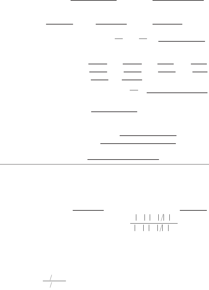
163
(iv) Recombination correction (two voltage method)
Polarizing voltages: V
l
(normal) = ____________ V V
2
(reduced) = _____________ V
Readings
d
at each V: M
1
= M
2
=
Voltage ratio V
1
/V
2
= __________________________ Ratio of readings M
1
/M
2
= ___________
Use Table 9 for a beam of type: ❏ pulsed ❏ pulsed–scanned
a
0
= a
1
= a
2
=
___________________
e,f
(v) Recombination correction (initial recombination):
Polarizing voltage (V): V
1
= V
2
= V
3
= V
4
=
Average readings at each voltage: M
1
= M
2
= M
3
= M
4
=
Coefficients of linear fitting: M
∞
= b =
Corrected dosimeter reading at the voltage V
1
:
M
Q
= M
1
k
TP
k
elec
k
pol
k
s
k
s
ini
= ❏ nC/MU ❒rdg/MU
4. Absorbed dose to water at the reference depth z
ref
Beam quality correction factor for user quality Q: k
Q
=
taken from ❏ Table 34 ❏ Other, specify:
Absorbed dose calibration of monitor at z
ref
,
D
w,Q
(z
ref
) = M
Q
N
D,w
k
Q
= Gy/MU
a
All readings should be checked for leakage and corrected if necessary.
b
If the electrometer is not calibrated separately, set k
elec
= 1.
c
M in the denominator of k
pol
denotes reading at the user polarity. Preferably, each reading in the equation
should be the average of the ratios of M (or M
+
or M
–
) to the reading of an external monitor, M
em
.
It is assumed that the calibration laboratory has performed a polarity correction. Otherwise k
pol
is
determined according to:
rdg at +V
1
for quality Q
o
: M
+
=
rdg at –V
1
for quality Q
o
: M
–
=
d
Strictly, readings should be corrected for polarity effect (average with both polarities). Preferably, each
reading in the equation should be the average of the ratios of M
1
or M
2
to the reading of an external
monitor, M
em
.
e
It is assumed that the calibration laboratory has performed a recombination correction. Otherwise the
factor k
′
s
= k
s
/k
s,Q
o
should be used instead of k
s
. When Q
o
is
60
Co, k
s,Q
o
(at the calibration laboratory) will
normally be close to unity and the effect of not using this equation will be negligible in most cases.
f
Check that
12
12
1
1
1
s
MM–
k–
VV–
ª
()
()
pol
+–
+–
o
Q
Q
M+M M
k = = __________
M+M M
È˘
Î˚
È˘
Î˚
ini
s
M
k
M
1
•
==
MMb/V
1/ 1/
•
=+
kaa
M
M
a
M
M
s
=+
Ê
Ë
Á
ˆ
¯
˜
+
Ê
Ë
Á
ˆ
¯
˜
=
01
1
2
2
1
2
2

165
Appendix I
RELATION BETWEEN N
K
AND N
D,w
BASED
CODES OF PRACTICE
The connection between the N
K
–N
D,air
formalism (used, for example, in the
IAEA’s TRS-277 [17] and TRS-381 [21]) and the N
D,w
formalism used in this Code of
Practice is, in principle, straightforward. There are, however, differences in detector
positioning and in the meaning of some correction factors which could lead to errors
if the user is not well aware of the changes. For this reason the connection between the
two formalisms is presented in detail in this appendix. An update of the information in
Ref. [17] was provided in the Ref. [21] Code of Practice for plane-parallel ionization
chambers (this also includes some changes to the data for cylindrical chambers).
I.1.
60
Co AND HIGH ENERGY PHOTON AND ELECTRON BEAMS
N
K
based protocols determine the absorbed dose to water at a reference depth
in a phantom in a two step process.
In the first step, a chamber factor in terms of absorbed dose to the cavity air,
N
D,air
, is derived. This is accomplished by relating the air kerma (free in air), K
air
,to
the mean absorbed dose
–
D
air
within the air cavity of the user ionization chamber in a
60
Co beam; that is
–
D
air
= K
air
(1 – g)k
att
k
m
k
cel
(46)
where the meaning of the factors g, k
att
and k
m
was given in Ref. [17]. The factor k
cel
in Eq. (46) takes into account the non-air equivalence of the central electrode of a
cylindrical ionization chamber during the chamber calibration in terms of air kerma
at
60
Co (see Ref. [21] and references therein). N
K
is defined as the ratio of K
air
to the
reading of a dosimeter during calibration at
60
Co, M; in the same way N
D,air
can be
defined as the ratio of
–
D
air
to the same reading, M. In the updated formalism given in
Ref. [21], N
D,air
is given by
N
D,air
= N
K
(1 – g)k
att
k
m
k
cel
(47)
This factor was called N
D
in Ref. [17], but the subscript ‘air’ was included in
Ref. [21] to specify without ambiguity that it refers to the absorbed dose to the air
of the chamber cavity; this is the N
gas
of the American Association of Physicists in
Medicine Task Group 21 [9]. Equation (47) superseded the equation given in
Ref. [17], which is

166
N
D
= N
K
(1 – g)k
att
k
m
(48)
Note that Eq. (48) in Ref. [17] did not include k
cel
and therefore N
D
did not relate
solely to the geometrical characteristics of the chamber, as the factor is intended to be
an indirect measure of the cavity volume
44
and therefore a chamber constant. The
factor k
cel
was instead included in Ref. [17] in a global factor p
cel
to account for the
combined effect of the central electrode, both during the calibration of the chamber
in air in a
60
Co beam and during subsequent measurements in photon and electron
beams in a phantom. The numerical value of N
D,air
for cylindrical chambers with a
1 mm diameter aluminium electrode (NE 2571) is a factor 1.006 greater than N
D
as
given in Ref. [17], even if the absorbed dose to water at
60
Co is the same due to can-
cellation of the two factors correcting for electrode effects (see below).
It is assumed that the N
D,air
factor derived at the
60
Co quality is also valid at the
user quality Q. The factor N
D,air
then allows the determination of the mean absorbed
dose within the air cavity at the user beam quality Q
–
D
air,Q
= M
Q
N
D,air
(49)
In the second step, the absorbed dose to water, D
w,Q
, at a point in a phantom
where the effective point of measurement of the chamber is positioned, is obtained
from the dose to air using the Bragg–Gray principle
D
w,Q
(P
eff
) = M
Q
N
D,air
(s
w,air
)
Q
p
Q
(50)
where M
Q
is the dosimeter reading at the beam quality Q corrected for influence
quantities, s
w,air
is the stopping-power ratio, water to air, p
Q
is the overall perturbation
factor of the ionization chamber for in-phantom measurements at a beam quality Q
and P
eff
is the effective point of measurement of the chamber, shifted from the
chamber centre towards the source. Note that in Ref. [17], where the beam quality Q
44
Note that if the volume of the chamber, V, was accurately known as is the case in a
primary standard ionization chamber, at the calibration quality N
D,air
would be defined as in
Ref. [12]:
(in J/kgC or Gy/C)
In the N
D,air
formalism W/e is assumed to be constant for photons and electrons [17], and there-
fore the factor N
D,air
depends only on the mass of air (Vr
air
) inside the cavity; it is thus a
constant of the chamber established for certain reference environmental conditions.
air
air
air
1
D,
DW
N
MV e
==
r

was denoted by ‘u’ (the user beam quality), the concept of an overall perturbation
factor was simplified; for photon and electron beams, p
u
was identified, respectively,
with the p
wall
and p
cav
perturbation factors used in Ref. [21] and in this Code of
Practice. It is emphasized that with Eq. (50) the absorbed dose to water is determined
at the point where P
eff
is situated.
As is well known (see Sections 1.6 and 4.2.5), an alternative to the use of the
effective point of measurement of the chamber is to consider a perturbation factor p
dis
that accounts for the effect of replacing a volume of water with the detector cavity,
when the reference point of the detector volume is taken to be at the chamber centre.
Equation (50) can be written as:
D
w,Q
(centre) = M
Q
N
D,air
(s
w,air
)
Q
p
Q
(51)
where for clarity the ‘centre’ of the chamber has been spelled in full. The expanded
form of the overall perturbation factor becomes
p
Q
= [p
cav
p
dis
p
wall
p
cel
]
Q
(52)
and the absorbed dose to water is determined at the position of the chamber centre.
The meaning of the different factors has been described in Section 1.6.
Two important remarks need to be made in relation to the correction for the cen-
tral electrode and to the use of the effective point of measurement.
(i) When the expressions for N
D,air
and for p
Q
, Eqs (47) and (52), respectively, are
inserted into Eq. (51), a product k
cel
p
cel
appears due to the effect of the central
electrode both in air and in water measurements. This product was called p
cel
in
Ref. [17], although it should have been named p
cel-gbl
to specify without ambi-
guity that it is a global correction factor. Although the values of k
cel
and p
cel
practically cancel each other at the quality of
60
Co gamma rays, it is important
to understand the difference between the p
cel
used in this Code of Practice (and
in Ref. [21]) and the p
cel-gbl
of Ref. [17], because only p
cel
plays a role in the
N
D,w
formalism as no in-air measurements are made.
(ii) When D
w,Q
is determined according to Eq. (50), the chamber is positioned with
its effective point of measurement at the reference depth where the absorbed
dose is required; the chamber centre is therefore deeper than the reference
depth. The use of Eq. (51) requires, on the other hand, that the chamber be posi-
tioned with its centre at the reference depth. The two different set-ups are illus-
trated in Fig. 18. It is clear that the two situations described by Eqs (50) and
(51) differ by the difference in per cent depth doses between P
eff
and the
chamber centre.
The connection between the present N
D,w
formalism and the N
D,air
formalism is
then established comparing Eqs (1) and (51) both for the same reference beam quality
167
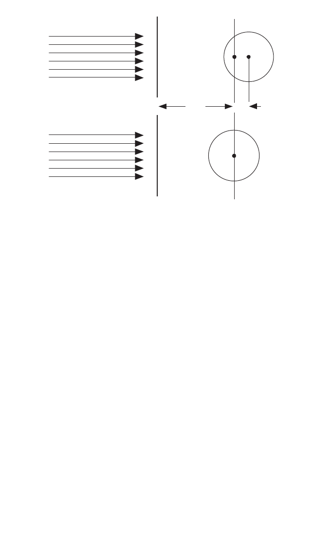
168
Q
o
. For the absorbed dose to water D
w,Q ,
o
determined at the same reference depth, it
follows that
N
D,w,Q
o
=
N
D,air
(s
w,air
)
Q
o
p
Q
o
(53)
or in expanded form
N
D,w,Q
o
= [N
K
(1 – g)k
att
k
m
k
cel
]
60
Co
(s
w,air
)
Q
o
[p
cav
p
dis
p
wall
p
cel
]
Q
o
(54)
where Q
o
usually refers to
60
Co gamma rays. The assumed constancy in N
D,air
allows
extending these relations to any reference quality, but the need for determining all the
factors entering into N
D,air
at the quality of
60
Co has been emphasized explicitly by
the subscript in the first square bracket. It is emphasized that the symbols and their
meaning correspond to those given in Ref. [21].
Details on the required stopping-power data and perturbation correction factors
are included in Appendix II. Factors related to the determination of the N
D,air
can be
found in Refs [17, 21].
FIG. 18. (a) In TRS-277 [17] the effective point of measurement of a cylindrical ionization
chamber is positioned at the reference depth z
ref
where the absorbed dose is required; the
chamber centre is deeper than z
ref
a distance d
c
equal to the shift of P
eff
(for example 0.6 r
cyl
for photon beams in Ref. [17]). (b) Except in electron and heavy ion beams, in the present code
of practice the centre of a cylindrical chamber is positioned at the reference depth z
ref
and the
absorbed dose is determined at this position.
P
eff
z
ref
(a)
(b)
d
c

I.1.1. A summary of notations used for calibration factors
The notation used in this Code of Practice for calibration factors is practically
identical to that used in Ref. [21], but differs somewhat from the symbols used in
Ref. [17]. A confusion between the different calibration factors might result in a con-
siderable error in the determination of absorbed dose to water during the calibration
of a beam, which may affect the radiotherapy treatments of a large number of
patients. For this reason, a summary of the various terms used to denote calibration
factors in the IAEA Codes of Practice and other publications is given here.
The chamber factor in terms of absorbed dose to cavity air N
D,air
was called N
D
in ICRU Report 35 [11] and in Ref. [17]. The subscript ‘air’was included in Ref. [21]
to specify without ambiguity that it refers to the absorbed dose to the air of the
chamber cavity. This is the symbol used in this Code of Practice. Extreme care should
be paid by the user to avoid confusing N
D,air
, or the former N
D
, with the calibration
factor in terms of absorbed dose to water N
D,w
.
The calibration factor in terms of absorbed dose to water N
D,w
was used in
Ref. [17] for low energy kV X rays; this is the only quality at which the calibration
factor in terms of absorbed dose to water was applied in that code of practice. In
Ref. [21] it has the same symbol as in this Code of Practice. The symbol N
D,w
has also
been adopted by the American Association of Physicists in Medicine Task Group 51
[51]. This calibration factor was referred to as N
D
in the American Association of
Physicists in Medicine Task Group 21 [9], where a relationship between N
gas
and N
D
similar to that described above was given. The symbol N
D
is also used in the calibra-
tion certificates issued by some standards laboratories and manufacturers instead
of N
D,w
.
As there is no uniformity in the adoption of unique symbols for calibration fac-
tors, users are advised to exercise extreme caution and confirm the physical quantity
used for the calibration of their detectors in order to avoid severe mistakes that could
jeopardize radiotherapy treatments. As can be easily seen in Eq. (53), the difference
between N
D,air
and N
D,w
at
60
Co is close to the value of the stopping-power ratio,
water to air, in
60
Co gamma rays (most perturbation factors are close to unity); a con-
fusion in the meaning of the factors could therefore result in an error in the dose
delivered to a patient of approximately 13%.
Examples of notations used in some codes of practice, dosimetry protocols, and
standards laboratories and manufacturers, to refer to calibration factors at the quality
of
60
Co gamma rays are given in Table 36.
I.1.2. Comparison of D
w
determinations
As already mentioned in Section 1.4, the adoption of this Code of Practice will
introduce small differences in the value of the absorbed dose to water determined in
169

170
clinical beams compared with previous codes of practice and dosimetry protocols
based on standards of air kerma (cf. Refs [17, 21]). It was also emphasized that any
conclusions drawn from comparisons between protocols based on standards of air
kerma and absorbed dose to water must take account of the differences between pri-
mary standards. Whereas details on the expected differences in various situations will
be published in the open literature, it is the purpose of this section to anticipate the
expected changes in the most common cases. For a given primary standard, the results
of a comparison will depend on the type and quality of the beam and on the type of
ionization chamber.
For
60
Co gamma radiation, which is generally better characterized than other
modalities, beam calibrations based on the two different standards, K
air
and D
w
, differ
by typically 1%. Figure 19 shows the ratio of absorbed dose to water in
60
Co
determined with calibration factors in terms of absorbed dose to water, and with
calibration factors in terms of air kerma together with TRS-277 [17] for some of the
ionization chamber types shown in Fig. 2. Although the differences lie in most cases
within the combined standard uncertainty of the two codes of practice, discrepancies
of this order are expected when N
D,w
and N
K
calibrations, traceable to the BIPM and
to most PSDLs, are used in hospitals and SSDLs. The change may be greater or
smaller when calibrations are traceable to laboratories lying at the extremes of the
TABLE 36. EXAMPLES OF NOTATION USED FOR CALIBRATION FACTORS
IN TERMS OF ABSORBED DOSE TO THE CAVITY AIR AND ABSORBED
DOSE TO WATER AT THE QUALITY OF
60
Co GAMMA RAYS
Publication or institution
Factor in terms of Factor in terms of
absorbed dose to the cavity air absorbed dose to water
This Code of Practice N
D, air
N
D,w
IAEA TRS-381 [21] N
D, air
N
D,w
IAEA TRS-277 [17] N
D
N
D,w
a
ICRU-35 [11] N
D
—
b
ICRU-64 [29] N
D, air
N
D,w
AAPM TG 21 [9] N
gas
N
D
AAPM TG 51 [51] —
b
N
D,w
Some standards laboratories
and manufacturers —
b
N
D
a
For low energy kV X rays only.
b
Not available or not applicable.
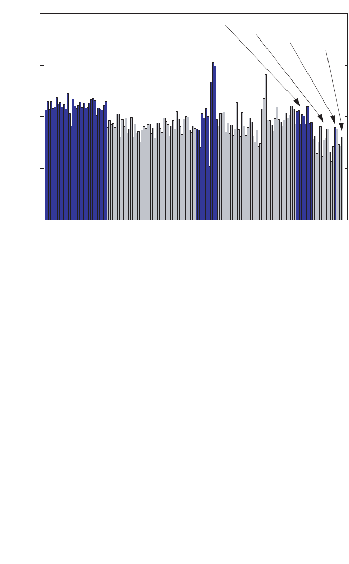
171
distributions shown in Fig. 4. Any systematic discrepancy between the two methods,
N
D,w
and N
K
, is most likely to be due to inaccuracies in the numerical factors and
expressions (for example, k
m
, p
wall
, etc.) used in the N
K
based formalism; in addition,
there is a possibility for a systematic effect in air kerma primary standards [31].
In the case of high energy photon and electron beam calibrations, only the sit-
uation involving calculated values of k
Q
is discussed here. The change in D
w
at
60
Co,
which is propagated to high energy beams, is the only significant contribution in high
energy photons, as most of the coefficients and factors involved in the calculation of
k
Q
factors are the same as in TRS-277 (2nd edition) [17] and no other differences are
expected. For electron beams, in addition to the propagated change in D
w
at
60
Co, the
second largest contribution will be due to the implementation of realistic stopping-
power ratios s
w,air
for clinical beams, as the basic data (s
w,air
for monoenergetic
FIG. 19. The ratio of absorbed dose to water in
60
Co determined with calibration factors in
terms of absorbed dose to water, N
D,w
and with calibration factors in terms of air kerma, N
K
,
using the IAEA TRS-277 [17] Code of Practice for some of the ionization chamber types
shown in Fig. 2. Both calibration factors are traceable to the BIPM. The differences are in
most cases within the combined standard uncertainty of the two Codes of Practice based on
N
D,w
and N
K
.
D
W
(N
+TRS-277 [17])
) / D
w
(
N
KD,w
0.99
1.00
1.01
1.02
1.03
NE 2561
and
NE 2611
NE 2571
NE 2581
PTW 30001
PTW 30002
PTW 30006
PTW 23333
PTW 30004

172
beams) remains practically the same; this will result in changes of the order of 0.5%.
As with
60
Co, the differences lie within the combined standard uncertainty of the two
Codes of Practice based on N
D,w
and N
K
.
I.2. KILOVOLTAGE X RAY BEAMS
For kilovoltage X ray beams the connection between the two formalisms, N
D,w
and N
K
, is established by different expressions depending on the beam quality.
For medium energy X ray beams and measurements made with the centre of a
cylindrical chamber at a reference depth of 2 g/cm
2
in a water phantom, the calibra-
tion factor in terms of absorbed dose to water is derived using
N
D,w,Q
o
= N
K,Q
o
([m
en
/r)
w,air
]
Q
o
p
Q
o
(55)
where N
K,Q
o
is the calibration factor in terms of air kerma measured free in air at the
Q
o
X ray calibration quality, [(m
en
/r)
w,air
]
Q
o
is the ratio of the mean mass energy
absorption coefficient, water to air, at the reference depth, and p
Q
o
is a perturbation
factor. The perturbation factor accounts for (i) the effect on the chamber response of
the difference in spectra at the chamber position for the calibration free in air and at
the reference depth in the water phantom, (ii) the replacement of water by the air and
chamber wall material, (iii) the influence of the stem on the chamber response in water
and free in air, and (iv) the effect on the chamber response of the waterproof sleeve.
The reference depth in Ref. [17] was specified as 5 g/cm
2
; however, data for
(m
en
/r)
w,air
at 2 g/cm
2
were also given. The data for perturbation factors have been
shown to be valid also at 2 g/cm
2
[104].
For establishing the connection at low energy X ray beams, it is necessary to
take into account the difference in response of a plane-parallel chamber free in air
compared to that on the surface of a full scatter phantom. This is because N
K
based
protocols yield the absorbed dose at a phantom surface when a plane-parallel
chamber is positioned free in air (see TRS-277, second edition [17]), whereas the
N
D,w
formalism yields the absorbed dose at the surface of a phantom when the
chamber is positioned with its reference point at the surface of a phantom. Thus, for
the air kerma formalism
D
w,Q
o
= M
Q
o
free air
N
K,Q
o
B [(m
en
/r)
w,air
]
Q
o
free air
p
Q
o
(56)
where the air kerma calibration factor N
K,Q
o
measured free in air includes the effect
of any material in which the ion chamber is embedded, B is the backscatter factor,
[(m
en
/r)
w,air
]
Q
o
free air
is the ratio of the mean mass energy absorption coefficients in free

air, and p
Q
o
is assumed to be unity for the plane-parallel chambers used. For a
formalism based on calibration factors in terms of absorbed dose to water
D
w,Q
o
= M
Q
o
surface
N
D,w,Q
o
(57)
From Eqs (56) and (57) it follows that
(58)
Data for the various factors in Eqs (55) to (58) have been given in the second edition
of Ref. [17] or may be found in other current dosimetry protocols and codes of prac-
tice [17, 96, 97]. The relationships given in this section allow both the comparison of
this Code of Practice with protocols based on calibration factors in terms of air kerma,
and also the use of this Code of Practice by means of N
D,w,Q
o
calibration factors
derived from standards of air kerma. A comparison of this Code of Practice with an
air kerma based protocol is effectively a verification of the factors [(m
en
/r)
w,air
]
Q
o
p
Q
o
and B. Because there has been some doubt, particularly in the last two, such compar-
isons will be valuable.
freeair
freeair
surface
en ,air
[( / ) ]
Q
o
D,w,Q K,Q w Q
Q
oo o
o
Q
o
M
NNB p
M
=
mr
173

Appendix II
CALCULATION OF k
Q,Q
o
AND ITS UNCERTAINTY
II.1. GENERAL
The beam quality correction factor k
Q,Q
o
is defined by Eq. (3). In this Code of
Practice, values for k
Q,Q
o
measured for a particular chamber should be used when
available. However, in most cases such data will not be available and calculated
values must be used. Under conditions where the Bragg–Gray cavity theory is valid,
values for k
Q,Q
o
may be calculated using Eq. (4):
(59)
In photon and electron beams, the basic monoenergetic data used for electron stop-
ping powers are those given in ICRU Report 37 [64], with the density effect model
due to Sternheimer. For proton and heavy ion beams the basic monoenergetic data
used for stopping powers are those given in ICRU Report 49 [118].
The value for (W
air
/e) of 33.97 J/C [129–131] is used in this Code of
Practice for all photon and electron beams. However, in view of some evidence of a
possible variation in W
air
between
60
Co and high energy photon and electron
beams [55], a component of uncertainty is included where appropriate. The value for
W
air
used for proton and heavy ion beams is discussed in the relevant sections of this
appendix.
In the absence of a consistent data set for perturbation factors, these are
necessarily treated in a less coherent way. Certain components are derived from
experiment, others by Monte Carlo or other calculations, and in some instances where
no reliable estimate can be made they are taken to be unity and an appropriate uncer-
tainty included.
The values for s
w,air
, W
air
and p for
60
Co, high energy photons, electrons,
protons and heavy ions, and the resulting k
Q,Q
o
factors and their uncertainties, are
discussed in separate sections below. In estimating the uncertainty of k
Q,Q
o
factors,
correlations between the various parameters are taken into account in an approxi-
mate manner. For low and medium energy X rays the Bragg–Gray cavity theory is
not valid and so no calculated values for k
Q,Q
o
are given in this Code of Practice for
these radiation types.
In this appendix the term ‘uncertainty’refers to the relative standard uncertainty
expressed as a percentage.
()
()
()
()
air
air
air air
QQQ
Q,Q
o
Q
Q
o
Q
o
o
w,
w,
s
W
sW
p
k
p
=
174

II.2.
60
Co GAMMA RADIATION
As noted previously, when the reference quality Q
o
is
60
Co, the symbol for
k
Q,Q
o
is simplified to k
Q
. The factors s
w,air
, W
air
and p
Q
for
60
Co appear in the denom-
inator of k
Q
for all radiation types and the values used are presented here.
II.2.1. Value for s
w,air
in
60
Co
The value s
w,air
= 1.133 for
60
Co was calculated by Andreo et al. [80] using the
monoenergetic electron stopping-power data tabulated in Ref. [64] with the density
effect correction due to Sternheimer. Uncertainties associated with the mean
excitation energies (I values) and density effect corrections give rise to a standard
uncertainty of 0.5%, which does not include the basic uncertainty inherent in the stop-
ping-power model. In addition, as a consequence of spectral differences between
60
Co beams, the uncertainty in assigning a stopping-power ratio to a particular
60
Co
beam is estimated to be 0.1%.
II.2.2. Value for W
air
in
60
Co
W
air
is the mean energy expended in air per ion pair formed, more usually
expressed in the form W
air
/e. The value for W
air
/e in
60
Co, for dry air, is taken to be
33.97 J/C [129–131]. The uncertainty of this value was estimated by Niatel et al.
[129] to be 0.2%.
II.2.3. Values for p
Q
in
60
Co
The overall perturbation factor includes all departures from the behaviour of an
ideal Bragg–Gray detector. In general, the contributing effects are small so that the
individual perturbation factors p
i
have values close to unity and can be treated inde-
pendently. For cylindrical chamber types, the overall perturbation factor is obtained
as the product
p
Q
= p
cav
p
dis
p
wall
p
cel
(60)
The component perturbation factors p
cav
,p
dis
,p
wall
and p
cel
are defined in Section 1.6.
For plane-parallel chamber types, p
dis
and p
cel
are omitted.
II.2.3.1. Values for p
cav
in
60
Co
The cavity correction p
cav
corrects for the perturbation of the electron fluence
due to scattering differences between the air cavity and the medium. Since transient
175

176
electronic equilibrium exists in
60
Co at z
ref
(5 g/cm
2
in water), the value for p
cav
is
taken to be unity (for both cylindrical and plane-parallel chamber types). The uncer-
tainty associated with this assumption is negligible (<0.1%).
II.2.3.2. Values for p
dis
in
60
Co
The displacement correction accounts for the fact that a cylindrical chamber
cavity with its centre at z
ref
samples the electron fluence at a point which is closer to
the radiation source than z
ref
. The correction depends on the inner radius of the cavity,
r
cyl
. Values derived from the measurements of Johansson et al. [132] have been used:
p
dis
= 1 – 0.004 r
cyl
(61)
where r
cyl
is in mm. The uncertainty of p
dis
was estimated by Johansson et al. [132]
to be 0.3%. Plane-parallel chamber types are positioned with the front of the air cavity
at z
ref
and it is assumed that no displacement correction is necessary; the uncertainty
in this assumption is estimated to be 0.2%.
II.2.3.3. Values for p
wall
in
60
Co
The factor p
wall
accounts for differences in the photon mass energy absorption
coefficients and electron stopping powers of the chamber wall material and the
medium. For cylindrical chamber types, a thin plastic waterproofing sleeve is nor-
mally used to protect the chamber. The formulation developed by Almond and
Svensson [133] and modified independently by Gillin et al. [134] and Hanson and
Dominguez-Tinoco [135] is used in this Code of Practice for the evaluation of p
wall
,
which includes the effect of the sleeve
αs
wall,air
(µ
en
/ρ)
w,wall
+ τ s
sleeve,air
(µ
en
/ρ)
w,sleeve
+(1–α–τ)s
w,air
p
wall
= ————————————————————————— (62)
s
w,air
The values used assume a PMMA sleeve of thickness 0.5 mm. The values used
for s
med,air
are those evaluated by Andreo et al. [80] using the electron stopping-power
data with Sternheimer density effect corrections tabulated in Ref. [64]. The ratios of
photon mass energy absorption coefficients are taken from Cunningham (see
Ref. [17]). The values for a and t are determined according to the expressions given
in Ref. [21]; that is
a(t
w
) = 1–e
–11.88t
w
(63)

and
t(t
s
) = e
–11.88t
w
(1 – e
–11.88t
s
) (64)
where t
w
and t
s
are, respectively, the thickness of the wall and the sleeve (in g/cm
2
).
These are based on the experimental data of Lempert et al. [136] for which no uncer-
tainty estimates were given. Andreo et al. [80] compared the calculated ratios of p
wall
for some materials with the experimental data of Johansson et al. [132] and found
agreement within 0.4%. Based on this, a combined standard uncertainty of 0.5% is
estimated for p
wall
.
This estimate applies also to plastic walled chambers having a thin conductive
layer or coating of graphite (‘dag’). The effect of this coating on p
wall
is difficult to
estimate and both Monte Carlo calculations and experiments have so far failed to
provide a satisfactory explanation of the underlying phenomena (see Ref. [137]). In
addition, manufacturers do not generally provide information on the exact thickness
of the coating, an exception being PTW (see footnote e in Table 3). An alternative
calculation of p
wall
for the PTW 30001 and 30010 chamber types has been made
using Eq. (62), taking the 0.15 mm graphite coating (of density r = 0.82 g/cm
3
) to be
the chamber wall and including the PMMA section of the wall as part of the water-
proof sleeve. This results in a value for p
wall
which is approximately 0.3% lower for
60
Co gamma rays. However, approximately the same decrease is obtained for p
wall
for
high energy photons, so that the effect of the graphite coating largely cancels in the
ratio of p
wall
values entering into the calculation of k
Q
. These agree within 0.1% with
the k
Q
values obtained for this type of chamber under the assumption that the entire
wall is made of PMMA (it is these latter values which are adopted for high energy
photons in this Code of Practice). The contribution to the uncertainty of p
wall
arising
from this effect is considered to be negligible (<0.1%).
For plane-parallel chamber types, p
wall
is problematic and variations of up to
3% between chambers of the same type have been reported [138]. It is for this reason
that the cross-calibration method is included in Section 7. Nevertheless, values have
been derived by a combination of measurement and calculation. Those given in Ref.
[21] for a number of chamber types have been used. In addition, values for the Attix,
Exradin and Holt chamber types have been taken from the calculations of Rogers
[139]. By assuming that the 3% variations represent the 67% (k = 1) confidence
interval of a normal distribution, the standard uncertainty is estimated to be 1.5%.
II.2.3.4. Values for p
cel
in
60
Co
For cylindrical chamber types, p
cel
corrects for the lack of air equivalence of the
central electrode. The correction for this effect is negligible for plastic and graphite
central electrodes, as shown by the Monte Carlo calculations of Ma and Nahum [140]
177

178
and the experimental determinations of Palm and Mattsson [141]. Both groups also
showed that an aluminium central electrode of diameter 1 mm, as used in many
Farmer type chambers, increases the chamber response by around 0.7% at the refer-
ence depth in
60
Co. These findings were in good agreement with the increased
response previously measured by Mattsson [142]. Thus a value for p
cel
of 0.993 has
been used here for chambers with an aluminium central electrode of 1 mm diameter.
The uncertainty of the most recent measurements is 0.2% [141]. It is important to
note that this value agrees with that used in Ref. [17], in which a value for p
cel-gbl
of
unity was assumed for all cylindrical chamber types having a 1 mm diameter alu-
minium electrode as a result of the cancellation between the effect in air and in water
measurements (see Appendix I).
II.2.4. Summary of values and uncertainties in
60
Co
Table 37 lists the values used for the factors p
dis
, p
wall
and p
cel
and for the
product s
w,air
p
Q
for the cylindrical chamber types listed in Table 3. The uncertainty
estimates as discussed above are summarized in Table 38.
II.3. HIGH ENERGY PHOTON BEAMS
The individual parameters entering in the numerator of Eq. (59) for high energy
photon beams are discussed below. In estimating the uncertainties, correlations
between the values for these parameters in
60
Co and in the high energy photon beams
are taken into account, since it is only ratios which enter into the k
Q
factor.
II.3.1. Values for s
w,air
in high energy photon beams
The Spencer–Attix stopping-power ratios s
w,air
are taken from the calculations
of Andreo [143, 144]. These calculations were performed by using the electron stop-
ping-power data tabulated in Ref. [64]. In estimating the uncertainty of s
w,air
relative
to the
60
Co value, correlations are not large because the main effects are those arising
from the uncertainty of the I value for water, which is important for
60
Co but not for
high energies, and the density effect model used for water, which is important only at
higher energies. A value of 0.5% has been estimated. The uncertainty in assigning
stopping-power ratios to a particular user beam quality is estimated to be 0.3%.
II.3.2. Value for W
air
in high energy photon beams
The value for W
air
normally used for high energy photon beams is the same as
that used for
60
Co, and this trend is followed in this Code of Practice. However, there

179
TABLE 37. VALUES FOR THE FACTORS p
dis
,p
wall
AND p
cel
AND FOR THE
PRODUCT s
w,air
p
Q
IN
60
Co GAMMA RADIATION, FOR VARIOUS CYLIN-
DRICAL AND PLANE-PARALLEL IONIZATION CHAMBERS
(the value s
w,air
= 1.133 is assumed, as noted in the text; for non-waterproof
cylindrical chambers the calculation of p
wall
includes a 0.5 mm thick PMMA sleeve)
Ionization chamber type
a
p
dis
p
wall
p
cel
s
w, air
p
Q
Cylindrical chambers
Capintec PR-05P mini 0.992 0.977 1.000 1.098
Capintec PR-05 mini 0.992 0.977 1.000 1.098
Capintec PR-06C/G Farmer 0.987 0.989 1.000 1.107
Exradin A2 Spokas 0.981 0.978 1.000 1.088
Exradin T2 Spokas 0.981 1.013 1.000 1.127
Exradin A1 mini Shonka 0.992 0.978 1.000 1.100
Exradin T1 mini Shonka 0.992 1.013 1.000 1.139
Exradin A12 Farmer 0.988 0.984 1.000 1.101
Far West Tech. IC-18 0.991 1.016 1.000 1.141
FZH TK 01 0.986 0.996 1.000 1.113
Nuclear Assoc. 30-750 0.992 0.986 1.000 1.109
Nuclear Assoc. 30-749 0.988 0.986 1.000 1.104
Nuclear Assoc. 30-744 0.988 0.986 1.000 1.104
Nuclear Assoc. 30-716 0.988 0.986 1.000 1.104
Nuclear Assoc. 30-753
Farmer shortened 0.988 0.986 1.000 1.104
Nuclear Assoc 30-751 Farmer 0.988 0.997 0.993 1.108
Nuclear Assoc 30-752 Farmer 0.988 0.991 0.993 1.101
NE 2515 0.988 1.000 0.993 1.112
NE 2515/3 0.987 0.992 0.993 1.102
NE 2577 0.987 0.992 0.993 1.102
NE 2505 Farmer 0.988 1.000 0.993 1.112
NE 2505/A Farmer 0.988 1.012 0.993 1.126
NE 2505/3, 3A Farmer 0.987 0.992 0.993 1.102
NE 2505/3, 3B Farmer 0.987 1.009 0.993 1.122
NE 2571 Farmer 0.987 0.992 0.993 1.102
NE 2581 Farmer 0.987 1.007 1.000 1.127
NE 2561/2611 Sec. Std 0.985 0.990 1.000 1.105
PTW 23323 micro 0.993 1.001 0.993 1.119
PTW 23331 rigid 0.984 1.001 0.993 1.109
PTW 23332 rigid 0.990 1.001 0.993 1.115
PTW 23333 0.988 1.001 0.993 1.113

180
TABLE 37. (cont.)
PTW 30001/30010 Farmer 0.988 1.001 0.993 1.113
PTW 30002/30011 Farmer 0.988 0.991 1.000 1.109
PTW 30004/30012 Farmer 0.988 0.991 0.993 1.101
PTW 30006/30013 Farmer 0.988 1.001 0.993 1.112
PTW 31002 flexible 0.989 1.001 0.993 1.114
PTW 31003 flexible 0.989 1.001 0.993 1.114
SNC 100730 Farmer 0.986 1.001 0.993 1.111
SNC 100740 Farmer 0.986 0.990 0.993 1.099
Victoreen Radocon III 550 0.990 0.993 1.000 1.115
Victoreen Radocon II 555 0.990 1.010 1.000 1.134
Victoreen 30-348 0.990 1.001 1.000 1.123
Victoreen 30-351 0.988 1.001 1.000 1.121
Victoreen 30-349 0.984 1.001 1.000 1.116
Victoreen 30-361 0.990 1.001 1.000 1.124
Scdx-Wellhöfer IC 05 0.988 0.986 1.000 1.104
Scdx-Wellhöfer IC 06 0.988 0.986 1.000 1.104
Scdx-Wellhöfer IC 10 0.988 0.986 1.000 1.104
Scdx-Wellhöfer IC 15 0.988 0.986 1.000 1.104
Scdx-Wellhöfer IC 25 0.988 0.986 1.000 1.104
Scdx-Wellhöfer IC 28 Farmer
shortened 0.988 0.986 1.000 1.104
Scdx-Wellhöfer IC 69 Farmer 0.988 0.997 0.993 1.108
Scdx-Wellhöfer IC 70 Farmer 0.988 0.991 0.993 1.102
Plane-parallel chambers
Attix RMI 449 1.023 1.159
Capintec PS-033 0.989 1.121
Exradin P11 1.018 1.154
Holt (Memorial) 1.004 1.138
NACP/Calcam 1.024 1.161
Markus 1.009 1.144
Roos 1.010 1.145
a
Some of the chambers listed in this table fail to meet some of the minimum requirements
described in Section 4.2.1. However, they have been included because of their current clinical
use.

181
is growing evidence [55] that this assumption could be in error by up to 1%. To
account for this, an uncertainty component of 0.5% is assumed for the W
air
ratio in
Eq. (59).
II.3.3. Values for p
Q
in high energy photon beams
The components of the perturbation correction as given by Eq. (60) are dis-
cussed separately. Only cylindrical chamber types are considered, since plane-parallel
chambers should not be used for reference dosimetry in high energy photon beams.
II.3.3.1. Values for p
cav
in high energy photon beams
As in
60
Co, transient equilibrium is assumed to exist at the reference depth and
the value for p
cav
is taken to be unity with a negligible uncertainty (<0.1%).
II.3.3.2. Values for p
dis
in high energy photon beams
In high energy photon beams the displacement effect is one of the major con-
tributions to the final uncertainty in k
Q
. The only set of experimental data available is
due to Johansson et al. [132], with an estimated uncertainty of 0.3%. However, these
values were determined mainly using accelerators of old design and at a time when
beam qualities were specified in terms of MV. The values for this correction factor
TABLE 38. ESTIMATED RELATIVE STANDARD UNCERTAINTIES OF THE
PARAMETERS ENTERING INTO THE DENOMINATOR OF Eq. (59) AT THE
60
CO BEAM QUALITY
Component
Chamber type
Cylindrical, u
c
(%) Plane-parallel, u
c
(%)
s
w, air
0.5 0.5
Assignment of s
w, air
to beam quality 0.1 0.1
W
air
/e 0.2 0.2
p
cav
<0.1 <0.1
p
dis
0.3 0.2
p
wall
0.5 1.5
p
cel
0.2 —
Combined standard uncertainty 0.8 1.6

182
given in Ref. [9] differ from the Johansson values by up to 0.6% for a Farmer type
chamber, and even more for chambers of larger diameter, but these differences can be
assumed to be consistent with the uncertainty estimate given above.
45
The values for
60
Co and for high energy photons must be correlated, but the extent of this correla-
tion is difficult to estimate. An estimate of the uncertainty of the p
dis
ratio entering
into the k
Q
value is 0.4%.
II.3.3.3. Values for p
wall
in high energy photon beams
As for
60
Co, Eq. (62) is used for the calculation of p
wall
, assuming a PMMA
sleeve of thickness 0.5 mm. The use of this expression instead of the more common
expression developed by Almond and Svensson [133] yields a maximum increase in
p
wall
of 0.2% for certain chamber types and beam qualities. The values for s
med,air
were evaluated by Andreo [143, 144] using the electron stopping-power data of
Ref. [64]. Values for the ratios of photon mass energy absorption coefficients are
taken from Cunningham (see Ref. [17]). Since the same data and equation are used
for p
wall
in
60
Co and in high energy photons, correlations are significant and the
uncertainty in the p
wall
ratio which enters into the k
Q
value is estimated to be 0.5%.
II.3.3.4. Values for p
cel
in high energy photon beams
The Monte Carlo calculations of Ma and Nahum [140] and the experimental
determinations of Palm and Mattsson [141] showed that a plastic or graphite central
electrode of 1 mm diameter has no effect on the response of an ionization chamber in
a water phantom irradiated by high energy photons. However, the presence of an alu-
minium electrode of diameter 1 mm increases the response by 0.43% to 0.75% for
photon beam qualities TPR
20,10
of 0.80 and 0.58, respectively. These results, assumed
to vary linearly with the beam quality, have been used for the calculation of k
Q
. The
experimental uncertainty of p
cel
is estimated to be 0.2%. However, there will be some
correlation in the p
cel
values for
60
Co and for high energy photons; the uncertainty in
the ratio of p
cel
factors is estimated to be 0.1%.
45
According to the ISO [32], when there is no specific knowledge about the possible
values of a variable X
i
within an interval, one can only assume that the variable X
i
lies within
a uniform rectangular distribution with an expected value x
i
in the midpoint of the interval and
an associated variance u
2
(x
i
) = a
2
/3, where a is the half-width of the interval.

183
II.3.4. Summary of uncertainties in high energy photon beams
Table 39 summarizes the estimates of the standard uncertainties for all of the
parameters entering into Eq. (59). For high energy photon beams the combined
standard uncertainty in the values for k
Q
is 1.0%.
It is worth pointing out that the estimated uncertainties given in Table 39
take into account, in an approximate manner, limitations in our current knowledge of
ionization chamber perturbation correction factors in photon beams. For example, it
has been shown by Seuntjens et al. [145] that, when the effect of the waterproof
sleeve is neglected in the calculation of p
wall
(as in Ref. [51]), a slightly better agree-
ment between experimental and calculated k
Q
values is obtained for some ionization
chambers at high photon beam energies. The magnitude of this effect is shown in
Fig. 20 for k
Q
values calculated as a function of TPR
20,10
for two commonly used
types of ionization chamber. A small, progressive decrease in the values for k
Q
at high
energies can be seen when PMMA sleeves of thickness 1 mm, 0.5 mm and no sleeve
at all are used in the calculation of p
wall
. The net effect is a gradual improvement in
the agreement with k
Q
values determined experimentally. It should be emphasized,
however, that a similar trend could be obtained by the use of values for the perturba-
tion correction factors p
cav
, p
dis
and p
cel
which differ from those used in this Code of
Practice. Neglecting the effect of the sleeve, or any other component, in the calcula-
tion of p
wall
should not be justified on the grounds of an improved agreement with
experimental k
Q
values. The calculated values used in this Code of Practice for all
chamber perturbation correction factors are those considered to be the best choice
TABLE 39. ESTIMATED RELATIVE STANDARD
UNCERTAINTY OF THE CALCULATED VALUES
FOR k
Q
FOR HIGH ENERGY PHOTON BEAMS
Component u
c
(%)
s
w, air
relative to
60
Co 0.5
Assignment of s
w, air
to beam quality 0.2
W
air
/e relative to
60
Co 0.3
p
cav
in
60
Co and in high energy photons <0.1
p
dis
relative to
60
Co 0.4
p
wall
relative to
60
Co 0.5
p
cel
relative to
60
Co 0.1
Combined standard uncertainty in k
Q
1.0
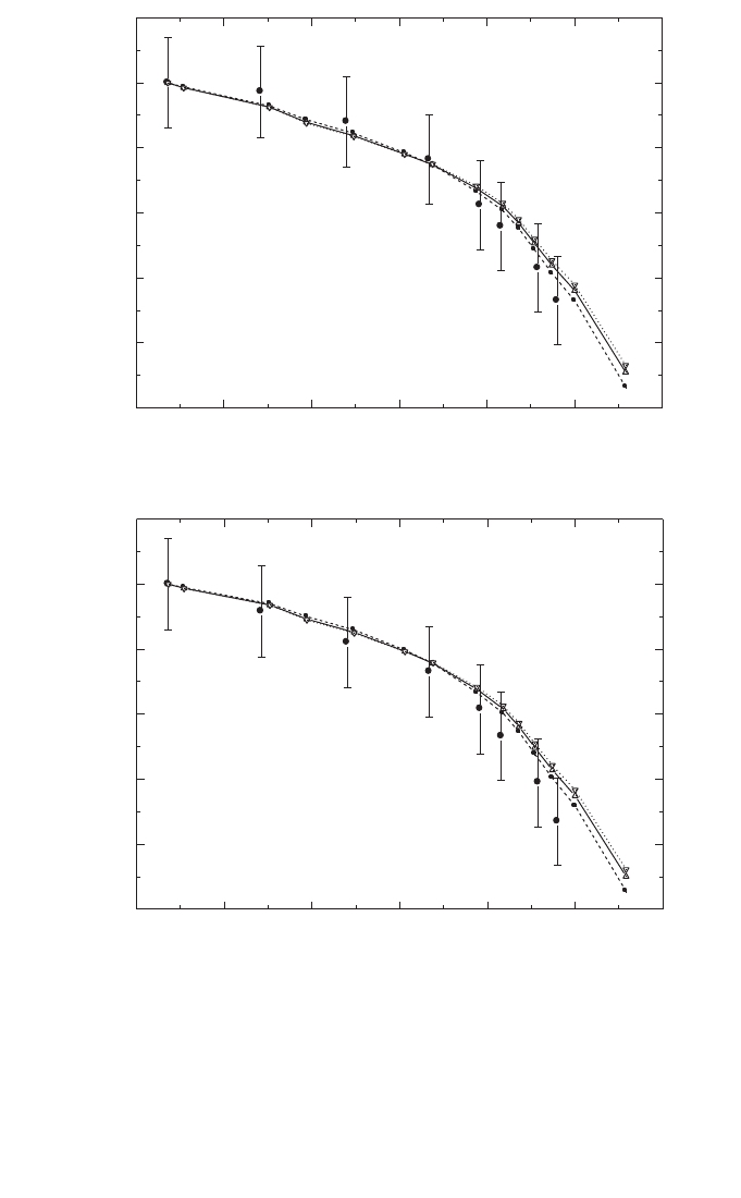
184
FIG. 20. Comparison of experimental and calculated k
Q
values for high energy photon beams,
where the influence of PMMA waterproof sleeves of different thicknesses in the calculation of
the p
wall
correction factors is shown for the chamber types (a) NE 2561/2611 and (b) NE 2571.
The experimental values (filled circles) were measured at the NPL , for which an uncertainty
of 0.7% has been estimated (see footnote c in Table 15). The sleeve thicknesses are 1 mm
(dotted lines, inverted triangles), 0.5 mm (solid lines, upright triangles) and no sleeve (dashed
lines, squares).
Photon beam quality, Q (TPR
20,10
)
k
Q
0.55 0.60 0.65 0.70 0.75 0.80 0.85
0.95
0.96
0.97
0.98
0.99
1.00
1.01
(b)
NE 2571
Photon beam quality, Q (TPR
20,10
)
k
Q
0.55 0.60 0.65 0.70 0.75 0.80 0.85
0.95
0.96
0.97
0.98
0.99
1.00
1.01
(a)
NE 2561/2611

according to the state of the art of ionization chamber dosimetry. It is emphasized
once again, however, that the preferred choice in this Code of Practice is the use of
experimentally determined values for the user chamber.
II.4. ELECTRON BEAMS
For electron dosimetry, the evaluation of k
Q,Q
o
depends on whether the calibra-
tion quality Q
o
is
60
Co or an electron beam. In the former case, k
Q
is evaluated as for
the other radiation types, taking the
60
Co values from Section II.2. In the latter case,
k
Q,Q
int
and k
Q
o
,Q
int
are introduced, but the factors (and uncertainties) contained in Q
int
cancel when the ratio of these is taken and so the choice of Q
int
is irrelevant to the
present discussion.
II.4.1. Values for s
w,air
in electron beams
Stopping-power ratios s
w,air
were calculated by Ding et al. [92] using Monte
Carlo simulations which included details of the accelerator heads of clinical linear
accelerators for a variety of accelerator types. The basic monoenergetic data were
those of Ref. [64]. The ratios calculated at z
ref
(as given by Eq. (24)) were empirically
fitted by Burns et al. [91] and it is these fitted values which are used in this Code of
Practice. The stopping-power ratio at z
ref
in an electron beam of quality R
50
is given
by
s
w,air
(z
ref
) = 1.253 – 0.1487(R
50
)
0.214
(R
50
in g/cm
2
) (65)
This relation is valid over the R
50
range from 1 to 20 g/cm
2
. The standard devi-
ation of the fitted values is 0.16%, which indicates that the values for s
w,air
at z
ref
for
different accelerators are not very different.
Estimation of the uncertainty follows the discussion of Section II.3 in relation
to correlations. When Q
o
is
60
Co, a standard uncertainty of 0.5% is appropriate for all
electron beam qualities. For calibration in an electron beam, this uncertainty is
reduced to 0.2%. The applicability to a particular accelerator of stopping powers
given by Eq. (65) was estimated by Burns et al. [91] to be less than 0.2%.
For depths other than z
ref
, the same basic data were fitted with an equation of
the form
(66)
where x = ln(R
50
) and y = z/R
50
is the relative depth. The values for the constants are
sz
abxcx dy
ex fx gx hy
w,
()
air
=
++ +
++ + +
2
23
1
185

186
a = 1.075 b = –0.5087 c = 0.0887 d = –0.084
e = –0.4281 f = 0.0646 g = 0.00309 h = –0.125
The standard deviation of the fit is 0.4%. Values derived using this equation are
given in Table 20 for a series of values of R
50
in the range from 1 to 20 g/cm
2
and for
values of the relative depth z/R
50
in the range from 0.02 to 1.2.
II.4.2. Value for W
air
in electron beams
As for high energy photons, the value for W
air
/e for dry air is taken to be
33.97 J/C and an uncertainty of 0.5% is included to account for a possible variation
in this value with electron energy. For calibration in a high energy electron beam and
use in a low energy beam, the uncertainty is smaller and a value of 0.3% is estimated.
II.4.3. Values for p
Q
in electron beams
Perturbation factors in electron beams are discussed extensively in Ref. [21],
and most of the values recommended therein are adopted in this Code of Practice. The
various components are as given in Eq. (60). Correlations between the uncertainties
for
60
Co and electron beams are assumed to be negligible. For calibration in a high
energy electron beam and use in a low energy beam, the uncertainty in the ratio of p
Q
factors is taken to be the same as that in p
Q
itself for the low energy.
Note that several data sets for perturbation factors previously expressed in
terms of E
z
, the mean energy at depth z, have been recast here in terms of R
50
. For
older data, where E
z
was calculated using the equation due to Harder [146], p
Q
data
were recast using Eq. (24) for z
ref
and the equations
E
o
= 2.33 R
50
(67)
R
p
= 1.271R
50
– 0.23
(all depths expressed in g/cm
2
) where E
o
is the mean energy at the phantom surface
and R
p
is the practical range in water. The first two relations have been widely used.
The third is taken from Ref. [147] and is derived from Monte Carlo simulations using
realistic clinical spectra. The resulting relation, obtained graphically, is
E
z
ref
= 1.23R
50
(68)
ref
ref
1
o
p
z
z
EE
R
ʈ
=-
Á˜
˯

Note that this equation is subject to the same limitations as the Harder equation
[146]. For more recent data for which improved E
z
values were derived using
Ref. [17], the data were recast using
E
z
ref
= 0.07+1.027 R
50
– 0.0048 (R
50
)
2
(69)
which is a fit to the data in Refs [17, 21] at the reference depths given by Eq. (24).
Note that perturbation factors expressed in terms of E
z
are normally determined
close to the dose maximum, but it is assumed here that they also apply at z
ref
. At low
energies, where z
ref
coincides with the dose maximum, this is a good assumption. At
higher energies it may not be so good, but in this regime perturbation factors are small
and vary slowly with depth so that the approximation should be sufficiently good.
Nevertheless, measurements of perturbation factors at z
ref
are to be encouraged;
experimental work by Huq et al. [148] has verified the above assumption for the
Farmer cylindrical chamber type.
II.4.3.1. Values for p
cav
in electron beams
For plane-parallel chamber types which are considered to be ‘well-guarded’,
that is having a radial guard area around the collecting volume of at least 1.5 times
the electrode spacing, p
cav
at z
ref
is assumed to be unity (with a negligible
uncertainty).
For a cylindrical chamber of internal radius r
cyl
, the p
cav
data of
Refs [17, 21, 132] have been recast in terms of R
50
and fitted with the equation
p
cav
= 1 – 0.0217r
cyl
exp(–0.153 R
50
)(r
cyl
in mm, R
50
in g/cm
2
) (70)
which is valid (at z
ref
) for r
cyl
in the range from 1.5 mm to 3.5 mm. For beam qualities
just above R
50
= 4 g/cm
2
, for which cylindrical chambers may be used, the cavity
correction for most chamber types is less than 3% and an uncertainty of 0.5% is
estimated.
II.4.3.2. Values for p
dis
in electron beams
In this Code of Practice, all chambers are positioned in electron beams so as to
minimize the displacement effect, and no explicit correction is applied. For plane-
parallel chamber types, the uncertainty in this procedure is estimated to be less than
0.2% and for cylindrical chamber types an uncertainty of 0.3% is assumed.
187

188
II.4.3.3. Values for p
wall
in electron beams
For plane-parallel chamber types, wall effects in electron beams are discussed
in detail in Ref. [21]; some more recent relative measurements are given by Williams
et al. [149]. In summary, despite evidence that backscatter differences between the
rear chamber wall and water may introduce a non-negligible p
wall
, there are at present
insufficient data to recommend explicit values and so p
wall
is taken to be unity. The
uncertainty associated with this assumption is difficult to estimate. The most likely
explanation for the observed results is that the graphite rear wall of the NACP
chamber type backscatters much like water (within 0.2%) and that the thin PMMA
rear wall of the Roos chamber type gives rise to the small backscatter deficiency (less
than 0.2%) hinted at in measurements relative to the NACP chamber type. An uncer-
tainty of p
wall
for well guarded chamber types of 0.3% at low energies is consistent
with this explanation.
For cylindrical chambers the p
wall
component in electron beams is generally
considered to be small (cf. Ref. [150]) and in this Code of Practice it is taken as unity.
The uncertainty of this assumption is estimated to be 0.5%.
II.4.3.4. Values for p
cel
in electron beams
For cylindrical chambers p
cel
must be considered for chambers which have an
aluminium central electrode. The calculations of Ma and Nahum [140] and the exper-
imental determinations of Palm and Mattsson [141] show that, for a Farmer type
chamber with an aluminium electrode of diameter 1 mm, a value of around 0.998 can
be used for all energies. A standard uncertainty of 0.1% is assumed.
II.4.3.5. Measured values for p
Q
for certain chamber types in electron beams
Three plane-parallel chamber types known to have insufficient guarding are
included because of their widespread use. Data for the PTW Markus chamber
M23343 and the Capintec PS-033 are given in Ref. [21]. When recast in terms of R
50
,
these data can be represented by
p
Markus,R
50
= 1 – 0.037exp(–0.27R
50
)(R
50
≥ 2 g/cm
2
) (71)
and
p
Capintec,R
50
= 1 – 0.084exp(–0.32R
50
)(R
50
≥ 2 g/cm
2
) (72)
Note the lower limits of validity of these equations and that both data sets apply
only at z
ref
. For all chamber types, the values given were determined by relative
measurements against a well guarded chamber type whose perturbation correction

189
was assumed to be unity. The standard uncertainty of the fitted values, which repre-
sent the total perturbation correction p
Q
, is less than 0.2%. However, the overall
uncertainty is limited by the uncertainty of p
wall
for the well guarded chamber type,
which is 0.3%.
II.4.4. Summary of uncertainties in electron beams
Table 40 summarizes the estimates of the standard uncertainties for all of the
parameters entering into Eq. (59) for the case when Q
o
is
60
Co. The combined stan-
dard uncertainty in the values for k
Q
is 1.2% for cylindrical chamber types and 1.7%
for plane-parallel chamber types, the latter dominated by p
wall
in
60
Co. Table 41 gives
the uncertainties for the case when Q
o
is a high energy electron beam (note that R
50
must not be less than 4 g/cm
2
when a cylindrical chamber is used). The uncertainties
are significantly lower than those for calibration in
60
Co, particularly for plane-
parallel chamber types due to the avoidance of p
wall
in
60
Co.
TABLE 40. ESTIMATED RELATIVE STANDARD UNCERTAINTY OF THE
CALCULATED VALUES FOR k
Q
FOR ELECTRON BEAMS (BASED ON THE
CALIBRATION QUALITY
60
Co)
Chamber type: Cylindrical Plane parallel
Beam quality range: Electrons
60
Co+electrons Electrons
60
Co+electrons
R
50
≥ 4 g/cm
2
R
50
≥ 4 g/cm
2
R
50
≥ 1 g/cm
2
R
50
≥ 1 g/cm
2
Component u
c
(%) u
c
(%) u
c
(%) u
c
(%)
s
w, air
relative to
60
Co — 0.5 — 0.5
Assignment of s
w, air
to
beam quality 0.2 — 0.2
W
air
/e relative to
60
Co — 0.5 — 0.5
p
cav
0.5 0.5 < 0.1 < 0.1
p
dis
0.3 0.4 0.2 0.3
p
wall
0.5 0.7 0.3 1.5
p
cel
0.1 0.2 — —
Combined standard
uncertainty in k
Q
— 1.2 — 1.7

190
II.5. PROTON BEAMS
For proton dosimetry, the calculated beam quality correction factors given in
this Code of Practice are based on a calibration in
60
Co. The values used for the
denominator of Eq. (59) are discussed in Section II.2.
II.5.1. Values for s
w,air
in proton beams
The values used are derived from the proton beam quality specifier R
res
(73)
where a = 1.137, b = –4.3 ¥ 10
–5
and c = 1.84 ¥ 10
–3
.
This equation is obtained as a fit to the monoenergetic stopping-power ratios
calculated using the Monte Carlo code PETRA [151]; the basic proton stopping
powers are taken from Ref. [118]. The PETRA stopping-power ratios include the
transport of secondary electrons and nuclear inelastic processes, which is not the case
for the ICRU stopping powers. PETRA calculates stopping-power ratios ‘in-line’;
that is, during the transport of the particles, following the Spencer–Attix cavity
w
c
sabR
R
,air res
res
=+ +
TABLE 41. ESTIMATED RELATIVE STANDARD UNCERTAINTIES OF THE
CALCULATED VALUES FOR k
Q,Q
o
FOR ELECTRON BEAMS (based on calibra-
tion in a high electron beam)
Chamber type: Cylindrical Plane parallel
Beam quality range: R
50
≥ 4 g/cm
2
R
50
≥ 1 g/cm
2
Component u
c
(%) u
c
(%)
s
w, air
relative to high energy beam 0.2 0.2
Assignment of s
w, air
to beam quality 0.3 0.3
W
air
/e relative to high energy beam 0.3 0.3
p
cav
relative to high energy beam 0.5 0
p
dis
relative to high energy beam 0.3 0.2
p
wall
relative to high energy beam 0.5 0.3
p
cel
relative to high energy beam 0.1 —
Combined standard uncertainty in k
Q,Q
o
0.9 0.6
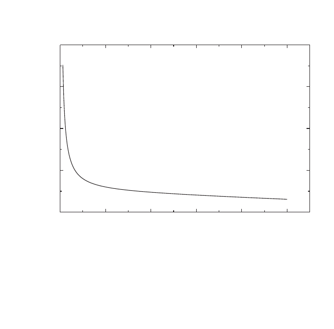
theory. In-line calculation has the advantage of exact scoring of the tracks ends. In
addition, any possible influence on the result of the number and size of the energy
scoring bins is avoided.
The resulting ratios are at most 0.6% higher than the corresponding ICRU
values. At the reference depth (as given in Table 30) the difference between the
PETRA and the ICRU calculated values is smaller (between 0.2% and 0.4% depending
on depth, energy and SOBP width) and is well within the stated uncertainties. The
statistical uncertainty of s
w,air
is estimated to be 0.2% [152]. The uncertainty of the
stopping-power ratios at the reference depth in a clinical beam is estimated to be 1%.
Figure 21 shows s
w,air
as a function of R
res
. No correlation with electron stopping
powers is assumed in evaluating the uncertainty of k
Q
factors. The uncertainty of
assigning stopping-power ratios to a given proton beam quality is estimated to
be 0.3%.
191
FIG. 21. Spencer–Attix (D = 10 keV) stopping-power ratios, water to air, for clinical proton
beams as a function of the beam quality index R
res
. The curve is a fit to monoenergetic stop-
ping-power ratios calculated by Medin and Andreo using the Monte Carlo code PETRA
[151, 152]. The data include the transport of secondary electrons and nuclear inelastic
processes, and the basic proton stopping powers are taken from ICRU Report 49 [118].
0 5 10 15 20 25
1.136
1.138
1.140
1.142
1.144
s
w,air
Residual range, R
res
(g/cm
2
)

192
II.5.2. Value for W
air
in proton beams
A comprehensive review of the literature on the value for W
air
(E), including
values obtained from the comparison of calorimetric and ionometric methods, is
presented in Ref. [116]. Moreover, the ICRU report presents an extensive discussion
on the difference between W
g
(E), the mean energy required for charged particles of
energy E to create an electron–ion pair in a gas g, and w
g
(E), the differential value.
Since in this Code of Practice the PETRA stopping-power ratios are recommended,
the values for W
air
(E) given in Ref. [116] (namely those obtained from comparisons
of calorimetric and ionometric measurements) must be corrected to account for the
small differences between the PETRA and ICRU stopping-power ratios. A procedure
using weighted medians, taking into account the statistical uncertainty of each value
[153, 154], yields the value W
air
/e=34.23 J/C, with a standard uncertainty of 0.4%.
This uncertainty can be compared with the uncertainty of 0.2% for the W
air
/e value
for electrons, which was obtained by the same statistical method.
46
Until more information is available, the value W
air
/e=34.23 J/C and a standard
uncertainty of 0.4% are recommended for proton dosimetry, and these values are used
in this Code of Practice.
II.5.3. Values for p
Q
in proton beams
Experimental information on perturbation factors in proton beams is currently
only available for a limited number of ionization chambers at a specific proton
energy; therefore all components are taken to be unity. The discussion below concen-
trates on the uncertainties.
II.5.3.1. Values for p
cav
in proton beams
The uncertainty of p
cav
may be considered in two parts, corresponding to the
contributions of secondary electrons and of heavier secondary particles. The slowing
down of the secondary electrons generated in a proton beam is similar to that for pho-
tons (
60
Co or high energy photons) and so the negligible uncertainty assumed for the
photon case may also be assumed for protons. The uncertainty of the heavier particle
contribution is taken to be 0.3%, for both plane-parallel and cylindrical chambers.
46
It is possible to arrive at the same average value using a simple “robust fit”, which
minimizes the influence of outliers (see Ref. [155]), but the procedure given in this reference
does not allow statistical weights to be taken into account in determining the uncertainty.

193
II.5.3.2. Values for p
dis
in proton beams
Since the reference depth (as given in Table 30) is situated in a uniform dose
region, p
dis
is taken to be unity. The magnitude of the correction is unlikely to exceed
0.5%. This includes the effect of possible ripples in the SOBP and a small dose
gradient in the plateau region. It should be stressed that this effect might depend on
the resolution of the modulation, influencing the dose uniformity in the SOBP. An
uncertainty of 0.2% is estimated for this correction, for both plane-parallel and cylin-
drical chambers.
II.5.3.3. Values for p
wall
in proton beams
Monte Carlo calculations by Palmans and Verhaegen [117] indicate a possible
effect on p
wall
due to the influence of secondary electrons. Recent measurements
[156] confirmed these calculations for certain wall materials; however, the effect
would not be larger than 0.5%. Therefore, p
wall
is currently taken to be equal to unity.
In estimating the uncertainty, a similar argument to that for p
cav
may be applied to
p
wall
, namely that the uncertainty arising from the secondary electron component
should be similar to that for photons, which is 0.5%. Likewise, a heavy particle con-
tribution of 0.3% is assumed. A component of 0.2% arising from the primary pro-
tons is also included, giving a combined uncertainty of 0.6%, for both plane-parallel
and cylindrical chambers.
II.5.3.4. Values for p
cel
in proton beams
For chamber types with an aluminium central electrode, a value for p
cel
of 0.997
was reported by Medin et al. [54] for a 170 MeV proton beam and of 1.00 by Palmans
et al. [156] in a 75 MeV proton beam. The value 1.0 is used in this Code of Practice
along with their stated uncertainty of 0.4%, which is adopted for all cylindrical ion-
ization chambers.
II.5.4. Summary of uncertainties in proton beams
Table 42 summarizes the uncertainty estimates and shows a combined standard
uncertainty in k
Q
for proton beams of 1.7% and 2.1% for cylindrical and plane-
parallel ionization chambers, respectively. The largest component of this uncertainty
is the uncertainty of s
w,air
and the uncertainty of p
wall
for plane-parallel ionization
chambers in the
60
Co reference beam.

194
II.6. HEAVY ION BEAMS
For heavy ion beams, the calculated beam quality correction factors given in
this Code of Practice are based on a calibration in
60
Co. Thus the values used for the
denominator of Eq. (59) are discussed in Section II.2.
II.6.1. Value for s
w,air
in heavy ion beams
The value for s
w,air
should be obtained by averaging over the complete spectrum
of primary particles and fragmented nuclei at the reference depth, as
(74)
E,i w
i
w
E,i i
i
EdE
s
SE dE
i
0
,air
air
0
(S ( ) / )
(()/)
•
•
F◊ r
=
F◊ r
Â
Ú
Â
Ú
TABLE 42. ESTIMATED RELATIVE STANDARD UNCERTAINTY OF THE
CALCULATED VALUES FOR k
Q
FOR PROTON BEAMS
Chamber type: Cylindrical Plane parallel
Protons
60
Co+protons Protons
60
Co+protons
Component u
c
(%) u
c
(%) u
c
(%) u
c
(%)
s
w, air
1.0 1.1 1.0 1.1
Assignment of s
w, air
to
beam quality 0.3 0.4 0.3 0.4
W
air
/e 0.4 0.5 0.4 0.5
p
cav
0.3 0.3 0.3 0.3
p
dis
0.2 0.4 0.2 0.3
p
wall
0.6 0.8 0.6 1.6
p
cel
0.4 0.5 — —
Combined standard
uncertainty in k
Q
— 1.7 — 2.1
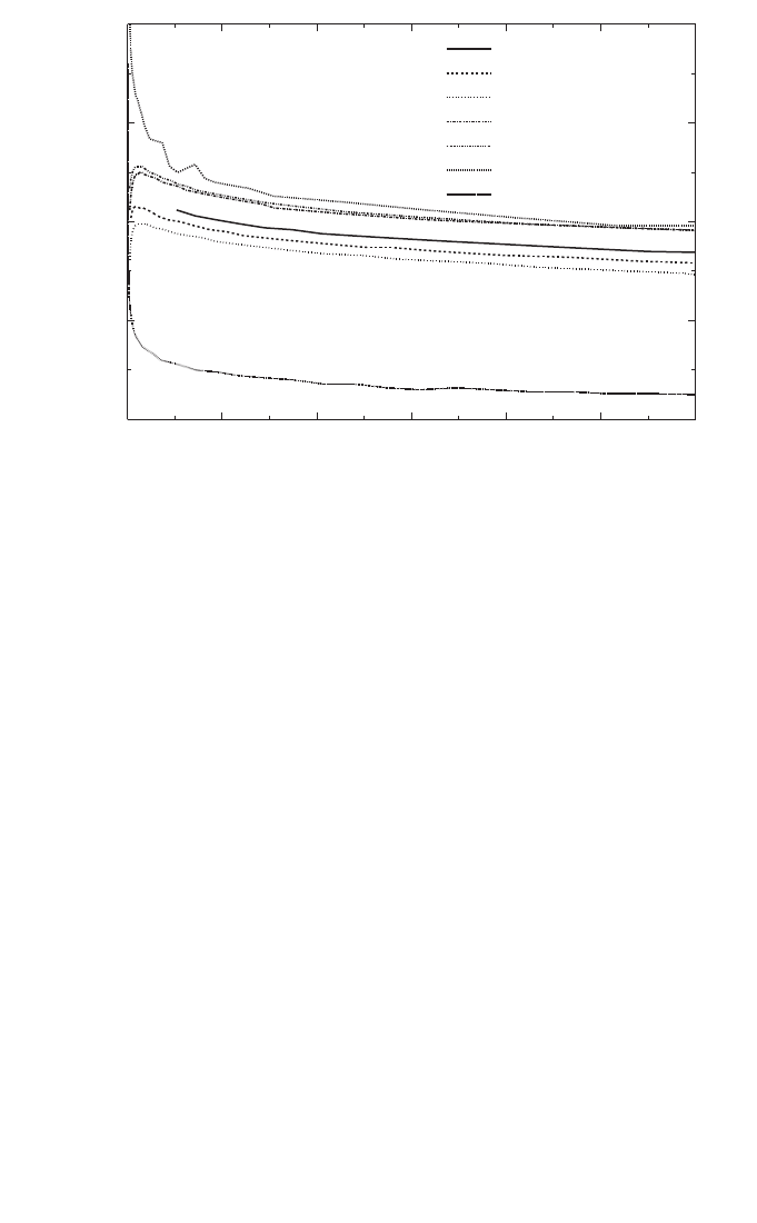
195
where (S
i
(E)/r)
m
is the mass stopping power at energy E for particle i in medium m
and F
E
is the particle fluence differential in energy. However, in view of the lack of
knowledge of the fluence spectra F
E
, substantial simplifications must be made.
Figure 22 shows calculated values for s
w,air
using several computer codes devel-
oped by Salamon [157] for helium, carbon, neon and argon ions, by Hiraoka and
Bichsel [158] for carbon ions, and by the ICRU [118] for protons and helium. As can
be seen from this figure, all values lie in the range from 1.12 to 1.14, including the
values for slow heavy ions. At present, a constant value of 1.13 is adopted for the
value of s
w,air
in heavy ion beams. The uncertainty of s
w,air
in heavy ion beams should
be much larger than that in proton beams because of its dependence on energy and
particle type. Uncertainties in the basic stopping powers must also be included. A
combined standard uncertainty of 2.0% has been estimated [123], which is adopted
here.
FIG. 22. Stopping-power ratio water to air for heavy ions calculated using the computer
codes developed by Salamon [157] (for C, Ne, Ar and He) and by Hiraoka and Bichsel [158]
(for C). Data for protons and He given in Ref. [118] are also included.
Residual range, R
res
(g/cm
2
)
0 5 10 15 20 25 30
1.120
1.125
1.130
1.135
1.140
C
Ne
Ar
He
p [118]
He [118]
C [158]
Water/air stopping-power ratio

II.6.2. Value for W
air
in heavy ion beams
As discussed above for s
w,air
, the value for W
air
should ideally be obtained by
averaging over the complete spectrum of primary particles and fragmented nuclei at
the reference depth
(75)
where w
i
(E) is the differential value of W
air
at energy E for particle i. The fluence
differential in energy, F
E
, should cover a wide energy spectrum and include all
primary and secondary particles.
There have been only a few experimental investigations of W
air
for high energy
heavy ions. Hartmann et al. [123] analysed the W
air
value for high energy carbon ions
and concluded that the value 34.8 J/Cshould be used. In the present code, W
air
values
for different ions were taken from the literature and are given in Table 43. The same
procedure as applied for the proton beams, taking into account the statistical
uncertainty of each value [153, 154], results in a value for W
air
/e=34.50 J/C with a
standard uncertainty of 1.5%.
Until more information is available, the value W
air
/e=34.50 J/C and a standard
uncertainty of 1.5% are recommended for heavy ion beam dosimetry, and these
values are used in this Code of Practice.
II.6.3. Value for p
Q
in heavy ion beams
At present, no experimental information is available on perturbation factors in
heavy ions and all components are taken to be unity. An overall uncertainty of 1.0%
is assumed, based on the evaluation of Hartmann et al. [123].
II.6.4. Summary of uncertainties in heavy ion beams
Table 44 summarizes the uncertainty estimates and shows a combined standard
uncertainty in k
Q
in heavy ion beams of 2.8% and 3.2% for the cylindrical and plane-
parallel chambers, respectively. This arises largely from the uncertainty of the
stopping-power ratio s
w,air
, and the value for W
air
.
air
0
air
0
(()/)
(()/)
()/
E,i i
i
HI
E,i i
i
i
SE dE
w
e
SE
dE
wE e
•
•
F◊ r
ʈ
=
Á˜
˯
F◊ r
Â
Ú
Â
Ú
196

197
TABLE 43. EXPERIMENTAL VALUES FOR W
air
/e FOR VARIOUS IONS AT
DIFFERENT ENERGIES
Ion W
air
/e (J/C) Energy (MeV/u) Reference
3
He 34.5 10.3 [159]
3
He 35.7 31.67 [160]
12
C 36.2 6.7 [159]
12
C 33.7 129.4 [159]
12
C 35.28 250 [161]
12
C 35.09 250 [162]
20
Ne 34.13 375 [162]
40
Ar 33.45 479 [162]
Ions with Z between 9 and 14 31.81 170 [163]
W
air
/e (weighted median) = 34.50 J/C ± 1.5%
TABLE 44. ESTIMATED RELATIVE STANDARD UNCERTAINTY OF THE
CALCULATED VALUES FOR k
Q
FOR HEAVY IONS
Heavy ions
60
Co+heavy ions Heavy ions
60
Co+heavy ions
Component: Cylindrical chambers Plane-parallel chambers
u
c
(%) u
c
(%) u
c
(%) u
c
(%)
s
w, air
2.0 2.1 2.0 2.1
W
air
/e 1.5 1.5 1.5 1.5
p (combined) 1.0 1.0 1.0 1.8
Combined standard
uncertainty in k
Q
— 2.8 — 3.2

198
Appendix III
PHOTON BEAM QUALITY SPECIFICATION
47
The specification of the quality of a photon beam has been the subject of
numerous studies due to its relevance in radiation dosimetry. However, no beam
quality specifier has been found that satisfies all possible requirements of being a
unique specifier for the entire energy range of photon energies used in radiotherapy
and all possible accelerators used in hospitals and standards laboratories. Discussions
raised in this context are described in this appendix in order to provide a reasoned
discussion of the advantages and disadvantages of using TPR
20,10
versus other spec-
ifiers, specifically PDD(10)
x
proposed by Kosunen and Rogers [164] and used in the
dosimetry protocol of the American Association of Physicists in Medicine Task
Group 51 [51]. For completeness, an overview of common photon beam quality spec-
ifiers used in radiotherapy dosimetry is given here based on the description provided
by the ICRU report on the dosimetry of high energy photon beams based on standards
of absorbed dose to water [29].
III.1. OVERVIEW OF COMMON PHOTON BEAM QUALITY SPECIFIERS
Most dosimetry protocols, based on both standards of air kerma and standards
of absorbed dose to water, have recommended the tissue phantom ratio, TPR
20,10
,as
specifier of the quality of a high energy photon beam [9, 12–14, 17, 19, 49, 50].
TPR
20,10
is defined as the ratio of water absorbed doses on the beam axis at the depths
of 20 cm and 10 cm in a water phantom, obtained with a constant source detector
distance (SDD) of 100 cm and a 10 cm × 10 cm field size at the position of the
detector. The parameter TPR
20,10
is a measure of the effective attenuation coefficient
describing the approximately exponential decrease of a photon depth dose curve
beyond the depth of maximum dose [82–84] and, more importantly, it is independent
of the electron contamination in the incident beam.
Prior to the use of dose ratios for specifying photon beam quality, the nominal
accelerator potential was the parameter most commonly used in photon beam
dosimetry. Measured ionization (charge or current) or absorbed dose ratios were first
used as a beam quality index in the dosimetry recommendations of the Nordic
Association of Clinical Physicists (NACP) [8, 165]. The measured ratio in a clinical
47
Part of this appendix has been adopted from Ref. [85] and is reproduced here with
the permission of the American Association of Physicists in Medicine.

199
treatment unit was, however, associated with a generic nominal accelerator energy
(nominal accelerating potential or nominal maximum energy, expressed in MV), which
was then used for the selection of conversion factors. A first attempt at improving the
NACP procedure was made in Ref. [9]. Data in Ref. [9] for stopping-power ratios, mass
energy absorption coefficient ratios, etc., were still given numerically as a function of
the nominal MV, but these data were associated in graphical form with measured
ionization ratios. There were, however, two limitations in the Ref. [9] method: (i) the
relation between measured and calculated ionization ratios was based on inaccurate
calculations, and (ii) the graphical procedure also involved a unique correspondence
between MV and ionization ratios, similar to the drawback pointed out for the NACP
recommendations [8, 165]. Andreo and Brahme [78] showed that the use of only the
nominal accelerator potential, ignoring the actual penetration properties of a clinical
beam, could yield variations of up to 1.5% in the stopping-power ratio. It is mainly for
this reason that the use of TPR
20,10
was considered to be the more appropriate choice
for radiotherapy beams, rather than using the nominal accelerating potential.
Other beam quality specifiers have been proposed for photon beam dosimetry
which are, in most cases, related to the depth of maximum absorbed dose and can,
therefore, be affected by the electron contamination at this depth. In addition, the use
of ionization distributions measured with thimble type ionization chambers is prob-
lematic, as the displacement of phantom material by the detector has to be taken into
account to convert ionization into dose distributions. This is avoided if plane-parallel
ionization chambers are used, but these are not common in photon beam dosimetry.
Based on percentage depth dose distributions, a widely disseminated recom-
mendation for specifying the quality of high energy photon beams was made in
Supplement 17 of the British Journal of Radiology (BJR) [87]. This supplement
defined the parameter d
80
as the depth of the 80% depth dose (i.e. 80% of the dose
maximum) for a 10 cm × 10 cm field size at an SSD of 100 cm. In Ref. [87] it was
pointed out that electron contamination should be considered a practical shortcoming
of the method. The use of d
80
as a photon beam quality index has also been endorsed
in Supplement 25 of the British Journal of Radiology [81], although other beam
quality specifiers, like PDD(10) below, are also considered. In its conclusions,
Supplement 25 also referred to contaminating electrons as the greatest problem for
normalization at z
max
, as by changing the dose at this depth electron contamination
can alter the apparent beam quality. It is interesting to note that even since
Supplement 11 of the British Journal of Radiology [166], the problem of electron
contamination and the need to normalize dose distributions at depths larger than z
max
has been addressed by different BJR supplements, but alternatives for a specifier
independent of electron contamination have not been proposed in this series of
publications.
The parameter PDD(10), the percentage depth dose at 10 cm depth, determined
under the same conditions of field size and SSD as d
80
, has the same limitation with

200
regard to the effect of electron contamination as d
80
. This parameter has been com-
monly used by accelerator manufacturers, associating it with an effective accelerator
potential. The work by LaRiviere [167], proposing a relation between the beam
quality specified in terms of MV and PDD(10), has been used by manufacturers to
justify the use of this parameter. This has, however, produced the paradoxical
situation where an accelerator could have an effective MV larger than the accelerator
electron energy.
LaRiviere [167] also proposed a relation between PDD(10) and the dose
weighted mean energy of the photon spectrum, which was suggested as an alternative
beam quality index. That proposal led Kosunen and Rogers [164] to investigate the
relation of PDD(10)
x
in a ‘pure photon beam’ (i.e. without electron contamination) to
stopping-power ratios. Based on the linearity of the relation obtained, they proposed
extending the use of PDD(10)
x
to specify the quality of photon beams and to select
conversion and correction factors. Kosunen and Rogers referred to the problem of the
difference between absorbed dose and ionization measurements with cylindrical
ionization chambers due to the use of a displacement (or replacement) factor, and also
emphasized that electron contamination should be removed from the photon beam for
measuring PDD(10)
x
. According to these authors the latter can be achieved using a
thin lead foil as filter, which has become the method recommended in Ref. [51].
III.2. ADVANTAGES AND DISADVANTAGES OF TPR
20,10
For clinical beams in the most widely used energy region (TPR
20,10
between
approximately 0.50 and 0.70)
48
, the small variation of stopping-power ratios, and
therefore in N
D,w
, with TPR
20,10
has an important advantage in the final uncertainty
of the determination of the absorbed dose to water at the reference point, as possible
errors in the measurement of TPR
20,10
do not yield a significant change in the value
of the stopping-power ratio [22]. From a compilation of 21 clinical spectra published
by different authors and 16 additional calculated spectra corresponding to clinical
beams [78], it has been shown that stopping-power ratios and TPR
20,10
are very well
correlated and lie on an almost universal curve. These stopping-power ratios can be
fitted to better than 0.15% for practically all the clinical spectra with a cubic
48
In a large survey carried out by the Radiological Physics Center in Houston [168], for
which the summary of RPC measured depth dose data was updated in 1996 (W. Hanson,
private communication), of approximately 1200 clinical accelerators investigated in North
America, more than 80% of the machines had a maximum nominal accelerating potential of
10 MV or less. This figure is expected to be even larger in developing countries.
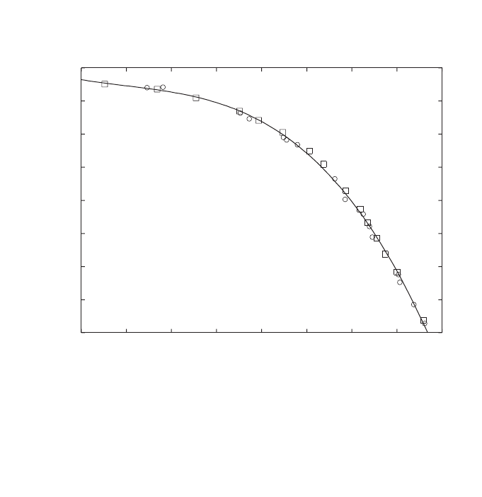
polynomial (see Fig. 23), where the stopping-power data and TPR
20,10
values are
taken from Ref. [144]. Measurements made by Followill et al. [79] on 685 photon
beams from 45 different accelerators with energies ranging from 4 MV to 25 MV
have shown very few TPR
20,10
values above approximately 0.8, and their estimated
water/air stopping-power ratios for the entire data set had a spread of ±0.25%. For the
few beams with TPR
20,10
higher than 0.75 or so, the steep gradient of the stopping-
power ratio versus TPR
20,10
curve could result in the propagation of possible errors in
measuring TPR
20,10
into larger variations in stopping-power ratios, and therefore in
k
Q
, than for lower beam qualities, but these variations will, in most cases, not be
larger than 0.5%.
There have been misinterpretations in the literature [147, 164] where data for
idealized beams (i.e. beams which do not exist in reality such as mono-energetic pho-
tons, thin target Schiff-bremsstrahlung spectra, etc.) which had been calculated for
illustrative and teaching purposes [169], have been used as an argument against the
201
s
w,air
1.06
1.07
1.08
1.09
1.10
1.11
1.12
1.13
1.14
0.45 0.50 0.55 0.60 0.65 0.70 0.75 0.80 0.85
TPR
20,10
f =a+b x+c x
2
+d x
3
a = 1.3614
b =-1.2963
c = 2.5302
d =-1.6896
r
2
=0.998
FIG. 23. Spencer–Attix (D = 10 keV, d
ICRU/Ashley
) water/air stopping-power ratios for clinical
photon beams as a function of the quality of the photon beam TPR
20,10
. Circles correspond to
spectra published by different authors (cf. Table 2 in Ref. [78]) and squares represent the
calculated spectra in the same reference. The solid line is a cubic polynomial, fitting the data
to better than 0.15%. The stopping power data and TPR
20,10
values are taken from Ref. [144].
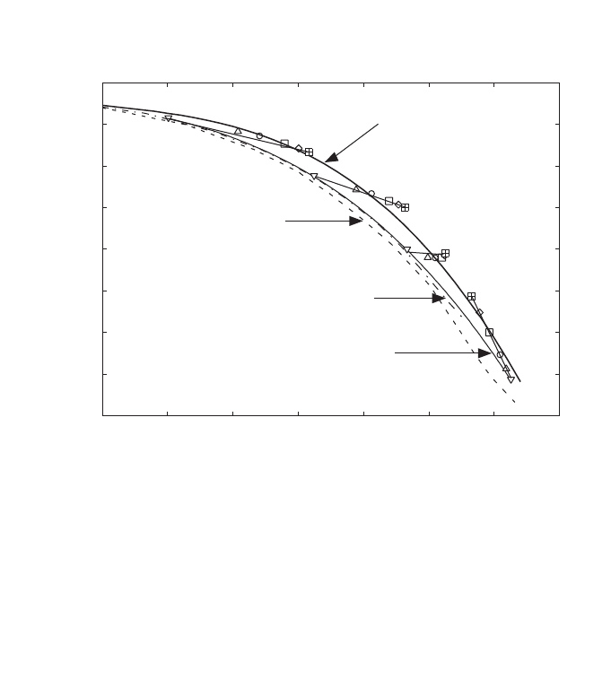
202
use of TPR
20,10
. Some of these data are reproduced in Fig. 24, and it is worth clari-
fying that the intention with such calculations was, in fact, to demonstrate that even
for those non-existing hypothetical beams, the largest variation in stopping-power
ratios would never exceed 1%. Unfortunately, these data have been misinterpreted
and the argument has been reversed and used as ‘evidence’against the use of TPR
20,10
[147, 164]. In any case it, should not be forgotten that, as in the case of kilovoltage
X ray dosimetry, in which the use of HVL must be complemented with information
on beam filtration and kV, TPR
20,10
can be meaningless if the accelerator potential
and the target and filter combinations used to derive stopping-power data are com-
pletely ignored.
The advantage of a small variation of stopping-power ratios with TPR
20,10
in
the majority of clinical environments has been argued [147, 164, 170] to be a
FIG. 24. Calculated water/air stopping-power ratios for various target and filter combina-
tions as a function of the quality of the photon beam TPR
20,10
. Data for tungsten targets
without filter are represented by the dashed–dotted line (thin target), the dashed line (thick-
ness equal to the electron csda range in tungsten) and the thin solid line (thickness equal to
one third of the electron csda range in tungsten). The symbols correspond to the r
o
/3-thick
target spectra for several “MV” (for clarity a line joins the symbols for each energy) after a
filtration with different thicknesses of lead (inverted triangles, no filter; normal triangles,
10 mm; circles, 20 mm; squares, 40 mm; trapezoids, 60 mm; crossed squares, 80 mm. The
thick solid line is the cubic fit to data calculated for clinical beams shown in Fig. 23. The figure
is adapted from Refs [53, 84].
s
w,air
1.06
1.07
1.08
1.09
1.10
1.11
1.12
1.13
1.14
0.50 0.55 0.60 0.65 0.70 0.75 0.80 0.85
10 MV
20 MV
50 MV
Cubic fit to data calculated
for clinical spectra
4 MV
Tungsten target r / 3
o
thick for 4–50 MV
(symbols: 0, 10, 20, 40, 60, 80 mm Pb filter)
Thin tungsten target
(without filter)
Tungsten target r
o
thick
(without filter)

203
limitation in a standards laboratory because different beam qualities might yield sim-
ilar ion chamber calibration factors. On the contrary, it has to be argued that if
chamber response varies slowly at a given beam quality range, this should not be a
problem as the chamber response both at the standards laboratory and at the hospital
will be similar.
The major argument against TPR
20,10
has been its limitation to select, with an
accuracy better than 0.5% or so, stopping-power ratios for the very high energy
photon beams produced by non-conventional clinical accelerators (for example
scanned beams without flattening filter) or accelerators used in one or two standards
laboratories having targets and filters considerably thicker than in clinical machines.
For example, as described by Ross et al. [171], the photon beams at the standards lab-
oratory in Canada are produced with a 4.5–6 cm thick aluminium fully stopping target
and 10–15 cm thick aluminium filters, which cannot be accommodated in the thera-
peutic head of a clinical accelerator, and have TPR
20,10
values in the range 0.75–0.83.
However, it is this capability of distinguishing a beam ‘forced to look like a clinical
beam’ by using non-clinical targets and filters, to achieve the same TPR
20,10
as in a
clinical beam, that makes this quality index attractive. At high photon energies, for
these unconventional and non-clinical accelerators, the steep gradient of the stopping-
power ratios versus TPR
20,10
might in some extreme cases yield stopping-power
ratios different from those resulting from a detailed Monte Carlo calculation, but still
the selection is well within the range of the estimated uncertainty of stopping-power
ratios which is of the order of 0.6% for high energy photons [22, 53]. At a standards
laboratory it is in this region where TPR
20,10
can easily show differences in calibra-
tion factors for similar beam qualities (but not identical) which can not be distin-
guished with specifiers based on percentage depth-dose distributions like PDD(10)
x
;
at this range of beam qualities TPR
20,10
is a more sensitive specifier than PDD(10)
x
.
On the practical side, TPR
20,10
is very simple to measure in a clinical beam
(usually vertical), as once the phantom and the detector are fixed, only the water level
has to be changed and the distance from the source to the detector is not relevant (TPR
or TAR are independent of distance from the source). Any errors in the position of the
detector will mostly cancel out in the measurements at two depths. For the same
reason, the uncertainty associated with the displacement effect or the position of the
effective point of measurement of the detector plays a minor role.
III.3. ADVANTAGES AND DISADVANTAGES OF PDD(10)
x
It is important to emphasize that, in principle, stopping-power ratios and k
Q
values could easily be related to any parameter indicating the penetration character-
istics of photon beams, as both stopping-power ratios and dose distributions are usu-
ally determined in a correlated manner using a Monte Carlo calculation. Figure 25
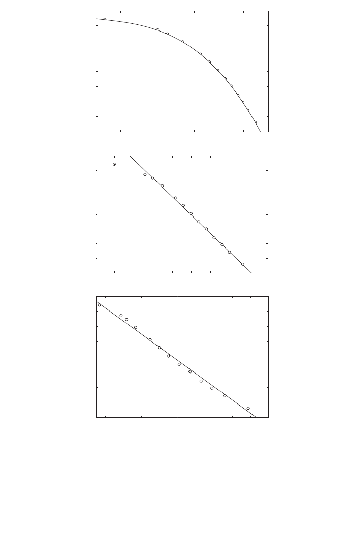
204
FIG. 25. Spencer–Attix (D = 10 keV, d
ICRU/Ashley
) water/air stopping-power ratios versus dif-
ferent photon beam quality specifiers: (a) TPR
20,10
, (b) PDD(10) and (c) d
80
. The basic
Stopping-power ratios are derived for the TPR
20,10
data in Ref. [81] using the cubic fit of
Fig. 23; these have been converted to the other specifiers using the data given in Ref. [81]. (b)
For PDD(10) the data point at 2 MV (circle with cross) has not been used in the linear fit. The
solid lines represent fits of the stopping-power ratios to each beam quality specifier for the
data set from Ref. [81].
TPR
20,10
0.50 0.55 0.60 0.65 0.70 0.75 0.80 0.85
1.06
1.07
1.08
1.09
1.10
1.11
1.12
1.13
1.14
1.06
1.07
1.08
1.09
1.10
1.11
1.12
1.13
1.14
1.06
1.07
1.08
1.09
1.10
1.11
1.12
1.13
1.14
(a)
PDD(10)
50 55 60 65 70 75 80 85 90 95
(b)
d
80
(mm)
50 60 70 80 90 100 110 120 130 140
f = a+b x
a = 1.176
b =-8.685 10
-4
r † = 0.993
f = a+b x
a = 1.288
b =-2.513 10
-3
r † = 0.993
(c)
s
w,air
s
w,air
s
w,air
TPR
20,10

illustrates the variation of water/air stopping-power ratios with different photon beam
quality specifiers, TPR
20,10
, PDD(10) and d
80
, using the beam quality parameters
given in Table 5.iii of BJR Supplement 25 [81]. The basic stopping-power ratios were
first obtained for the TPR
20,10
data using the fit given in Fig. 23 for clinical beam
spectra, and then were converted to the other specifiers using data from Ref. [81].
The fits included in the plots show that it is possible to derive a close relation
for any specifier (the data point at 2 MV has not been included in the fit for PDD(10)
given here, nor was it included in those given in Refs [164, 170, 172, 175]), and
similar plots could have been produced also for broad or narrow beam attenuation
coefficients. Note in particular that the linear correlation with the beam quality spec-
ifier recommended in Ref. [81], d
80
, is excellent for the entire range of energies used
in this comparison. Considering that the depth dose data have been averaged over
many types of clinical accelerators (from Ref. [81]), it could be assumed that these
simple linear fits are representative of clinical data. However, as the electron contam-
ination varies from machine to machine, this indirect procedure has never been
recommended and only the data expressed as a function of TPR
20,10
can be used inde-
pendently of contamination.
Calculating the stopping-power ratio data directly as a function of PDD(10) or
d
80
for realistic beams is not possible due to the lack of information on the spectra of
contaminant electrons, which would be required as input to the calculations. Instead,
the parameter PDD(10)
x
, i.e. PDD(10) for ‘pure photon beams’, has been recom-
mended to select stopping-power ratios [147, 164]. The problem is that in reality
‘pure photon beams’ do not exist. Therefore, beam quality specification must rely
either on a simple practical parameter which is truly related to the intrinsic physics of
photon interactions (like a practical attenuation coefficient, which is equivalent to
using TPR
20,10
), or the problems associated with electron contamination will cancel
any possible theoretical advantage in a simple linear fit valid for most practical
beams. In the latter case, the difficulty with relating a ‘pure photon beam’ parameter
to a parameter easily measurable in a hospital is a major limitation which will be
discussed below. A related problem which has received little attention in the assign-
ment of stopping-power ratios to Monte Carlo calculated depth dose distributions is
the statistical noise that appears in depth dose data. Figure 26 illustrates this situation,
which is specially relevant in the region around the depth of maximum dose, z
max
. The
histogram in the figure corresponds to the simulation, using the Monte Carlo code
DOSRZ/EGS4 [174], of 15 million histories of 10 MeV monoenergetic photons in a
1 mm depth grid, and shows the difficulty of finding values of the dose at z
max
and at
a single depth (for PDD(10) or d
80
) due to the statistical noise of the Monte Carlo
data. For comparison, the solid line corresponds to a convolution of calculated energy
deposition kernels which overcomes this problem; the procedure has been used to
derive the correlation between TPR
20,10
and stopping-power ratios in Ref. [144]
shown in Fig. 23.
205
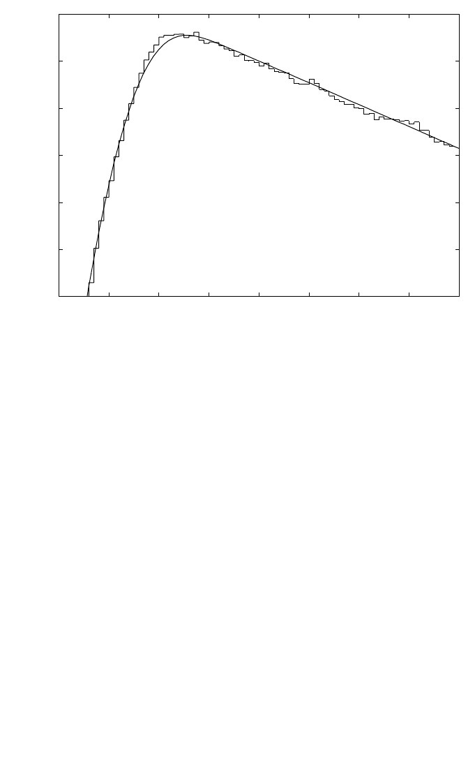
The linearity of the relation between PDD(10)
x
and stopping-power ratios for
all types of beams, even for those not available in hospitals, has been a major argu-
ment for promoting the use of PDD(10)
x
as a photon beam quality specifier and min-
imizing the importance of electron contamination. There have been efforts by some
standards laboratories to have PDD(10)
x
accepted so that these laboratories can have
their accelerators showing a specification similar to that found in clinical machines,
even if the accelerator energy is very different. It is unfortunate that practically all the
experimental comparisons showing the ‘superiority’ of PDD(10)
x
over TPR
20,10
have
been made on non-clinical accelerators at standards laboratories [171, 175]. In a
recent publication [176] where k
Q
values were determined in the photon beams of a
standards laboratory, a statement concluding “support PDD(10) as a better beam
quality specifier” was given even when the electron contamination contribution to the
dose at z
max
had been estimated in a crude way and PDD(10) corrected according to
206
FIG. 26. Comparison between central axis depth dose distributions for 10 MeV monoener-
getic photon beams obtained from Monte Carlo simulations using the code DOSRZ/EGS4
[174] (the histogram corresponds to 15 million photon histories using a 1 mm depth grid) and
from the convolution of calculated energy deposition kernels (solid line). The plot illustrates
the difficulty of deriving values of the dose at z
max
and at a single depth owing to the statis-
tical noise of the Monte Carlo data, but the problem can be overcome with the use of kernels.
The data are taken from Ref. [144].
Depth in water (cm)
0.125
0.130
0.135
0.140
0.145
0.150
0.155
20 30 40 50 60 70 80 90 100
Energy deposition per incident photon (MeV·cm
-2
·g
-1
)
10 MeV photons

such an estimation. Other major laboratories, on the other hand, do have clinical
beams or intend to install a clinical treatment head.
As all the specifiers based on percentage depth dose distributions are affected
by the electron contamination of the beam, identical photon spectra with different
contamination would appear as having different qualities, even when their dosi-
metric properties at depth (attenuation, stopping-power ratios, etc.) are the same.
These specifiers thus have a closer relation to the manufacturer’s design of an accel-
erator treatment head, which is the major source of contaminant electrons, than with
the physics governing the penetration of photon beams. To remove electron contam-
ination an appropriate ‘electron filter’should be used. The ideal solution would be a
purging magnet (cf. Ref. [84]), but this is seldom available and only some versions
of racetrack microtron accelerators include such a device. As already mentioned, the
use of a lead foil has been suggested by a group of authors [164, 172], and this has
been the recommendation of the American Association Physicists in Medicine Task
Group 51 protocol [51]. It is surprising that a material like lead has been recom-
mended, when it has long been well known that lead in itself is an additional source
of contaminant electrons. This was recognized in early radiotherapy in relation with
skin sparing problems produced by electrons originated in lead blocks and, for
instance, ICRU Reports 10b and 10d [98, 177] recommended using materials of
intermediate atomic number, such as copper, iron or brass, as filters to minimize
electron production.
Having decided that an electron lead filter will be used, a relation between the
uncontaminated non-clinical photon beam and the contaminated clinical beam must
be established for the accelerator and filter used in specific conditions. The term
uncontaminated deserves special attention because the lead filter used to measure
depth dose data produces new electron contamination whose consequences have not
been studied in detail for a large number of clinical photon spectra. What is available
today is a set of empirical equations, derived for a few examples, all requiring several
steps and the use of multiple parameters and approximations. Rogers [147], for
example, has provided a relationship between PDD(10) and PDD(10)
x
which is based
only on two sets of measured data. Also, the series of publications by Rogers and
colleagues on this topic [164, 170, 172, 173] is based on a so-called ‘standard set’ of
photon beam spectra, which contains only five typical clinical beams (those calcu-
lated by Mohan et al. [178]), but no further accelerator photon beams have been
modelled and simple electron spectra have been used as inputs to some of the
necessary calculations [173]. Whereas the scientific interest of these calculations is
unquestionable, on the practical side one could question if the uncertainty introduced
by the various steps and general fits does not counter balance the hypothetical advan-
tage of using a ‘pure photon beam’ parameter.
An elementary question which may be raised in relation to this topic is, if all
electron contamination can be removed from z
max
, and a depth dose curve can be
207

measured with satisfactory accuracy by every user, then why is the depth of maximum
dose z
max
not recommended for photon beam calibration, instead of at a depth of
10 cm? This would eliminate the step of transferring the dose from a larger depth to
z
max
, which is used by most medical physicists for performing clinical reference
dosimetry. In this case, only a relative measurement between the filtered and the non-
filtered beam would be necessary, exactly as for measuring relative field outputs. This
question has not been addressed by the various publications which recommend that
PDD(10)
x
be used as a beam quality specifier [164, 170, 172, 173] nor by Ref. [51].
On the practical side, problems may arise in the measurement of PDD(10)
x
,in
addition to those related to the positioning of the lead filter whose distance to the
phantom surface may be critical [173]. Because only one depth is relevant, this speci-
fier is affected by errors in the positioning of the chamber at depth, although the influ-
ence on the determination of absorbed dose is probably very small. Care should be
taken when PDD(10)
x
is measured with cylindrical chambers due to the position of the
effective point of measurement of the ionization chamber, or to the need for using a dis-
placement (replacement) factor for the measurement at 10 cm depth but not at the depth
of the maximum absorbed dose. The depth of the maximum dose may be different in
the filtered and non-filtered beams, so that accurate depth doses down to at least 10 cm
depth need to be measured in both conditions, and it is well known that these may vary
with the type of detector and measuring device used. Any systematic error in the
measuring set up (SSD, depths, etc.) will also change the measured PDD(10)
x
.
These practical problems and their influence on the final dose determination
have been omitted in most occasions where PDD(10)
x
has been recommended as a
beam quality specifier [164, 170, 172, 173] and in Ref. [51]. The user may then
decide that it is not worth measuring PDD(10)
x
under careful reference conditions.
Even the possible impact of electron contamination has been minimized to such an
extent in these references, where often a clear distinction between PDD(10)
x
and
PDD(10) is omitted in the concluding remarks [164, 172], that users may feel it is
unnecessary to use an electron filter for measuring PDD(10)
x
, and use instead
PDD(10) in an open beam (or the typical values given in Ref. [81]). This may be
acceptable for relatively clean beams, yielding errors probably less than 0.5%, but
may have detrimental dosimetry consequences for beams with significant electron
contamination. The risk of users oversimplifying dosimetry procedures should not be
ignored or otherwise the possible advantages of implementing new dosimetry
protocols may be jeopardized.
III.4. CONCLUDING REMARKS
The general conclusion is that there is no unique beam quality specifier that
works satisfactorily in all possible conditions for the entire energy range of photon
208

energies used in radiotherapy and all possible accelerators used in hospitals and in
standards laboratories.
The most recent dosimetry protocols or codes of practice, based on the calibra-
tion of ionization chambers in terms of absorbed dose to water, use a photon beam
quality specifier in terms of TPR
20,10
[49, 50], and this is also the choice in the present
International Code of Practice. The American Association of Physicists in Medicine
Task Group 51 protocol [51] in North America uses PDD(10)
x
.
For a hospital user there is strictly no advantage of one index over the other, as
both sets of data, PDD and TPR (or TMR), are available for routine clinical use.
However, there are more practical problems with measuring PDD(10)
x
than with
TPR
20,10
, and errors in determining the beam quality index may have in general more
adverse consequences with PDD(10)
x
than with TPR
20,10
. The final impact on clinical
photon beam dosimetry resulting from the use of different photon beam quality
specifiers to select k
Q
values, is that they are not expected to yield a significant change
(i.e. more than 0.5%, and in most cases they agree within 0.2% [179]) in the value of
the absorbed dose to water in reference conditions for most clinical beams. This
difference is considerably smaller than the combined uncertainty of the different
factors and coefficients used in photon dosimetry. In addition, for standard laborato-
ries the use of PDD(10)
x
would require having different set ups for measuring beam
quality and for the calibration of ionization chambers, which may result in increased
calibration costs for the user. A change that does not improve photon dosimetry at the
hospital and has so many complications from a practical point of view for the user
does not appear to be justified.
209

Appendix IV
EXPRESSION OF UNCERTAINTIES
The evaluation of uncertainties in this Code of Practice follows the guidance
given by the ISO [32]. In 1986 the ISO was given the task of developing detailed
guidelines for the evaluation of uncertainties based on the new unified approach out-
lined in the BIPM Recommendation INC-1. These recommendations were approved
by the Comité International des Poids et Mesures [180]. This effort resulted in the
issue in 1993 of the ISO document entitled ‘Guide to the Expression of Uncertainty
in Measurement’, with a first corrected edition published in 1995 [32]. The guide
should be consulted for further details. This appendix provides practical implemen-
tation of the ISO recommendations, based on the summaries provided in
Refs [17, 33].
IV.1. GENERAL CONSIDERATIONS ON ERRORS AND UNCERTAINTIES
Contrary to earlier practice, when the terms error and uncertainty were used
interchangeably, the modern approach, initiated by the Comité International des Poids
et Mesures [180], distinguishes between these two concepts. Traditionally, an error
has been viewed as having two components, namely a random component and a sys-
tematic component. According to present definitions, an error is the difference
between a measured value and the true value. If errors were known exactly, the true
value could be determined; in reality, errors are estimated in the best possible way and
corrections are made for them. Therefore, after application of all known corrections,
errors do not need any further consideration (their expectation value being zero) and
the quantities of interest are uncertainties. An error has both a numerical value and a
sign. In contrast, the uncertainty associated with a measurement is a parameter that
characterizes the dispersion of the values ‘that could reasonably be attributed to the
measurand’. This parameter is normally an estimated standard deviation. An uncer-
tainty, therefore, has no known sign and is usually assumed to be symmetrical. It is a
measure of our lack of exact knowledge, after all recognized systematic effects have
been eliminated by applying appropriate corrections.
Uncertainties of measurements are expressed as relative standard uncertainties
and the evaluation of standard uncertainties is classified into type A and type B. The
method of evaluation of type A standard uncertainties is by statistical analysis of a
series of observations, whereas the method of evaluation of type B standard uncer-
tainties is based on means other than statistical analysis of a series of observations.
In the traditional categorization of uncertainties it was usual to distinguish
between random and systematic contributions. This is undesirable because classifying
210
the components instead of the method of evaluation is prone to ambiguities. For
example, a random component of uncertainty in one measurement may become a
systematic component of uncertainty in another measurement in which the result of
the first measurement is used as an input datum.
IV.2. TYPE A STANDARD UNCERTAINTIES
In a series of n measurements, with observed values x
i
, the best estimate of the
quantity x is usually given by the arithmetic mean value
(76)
The scatter of the n measured values x
i
, around their mean ¯x can be character-
ized by the standard deviation
(77)
and the quantity s
2
(x
i
) is called the sample variance.
We are often interested in the standard deviation of the mean value, written as
s(¯x), for which the general relation
(78)
applies. An alternative way to estimate s(¯x) would be based on the outcome of several
groups of measurements. If they are all of the same size, the formulas given above can
still be used, provided that x
i
is now taken as the mean of group i and ¯x is the overall
mean (or mean of the means) of the n groups. For groups of different size, statistical
weights would have to be used. This second approach may often be preferable, but it
usually requires a larger number of measurements. A discussion of how much the two
results of s(¯x) may differ from each other is beyond this elementary presentation.
The standard uncertainty of type A, denoted here by u
A
, will be identified with
the standard deviation of the mean value; that is
u
A
= s(¯x) (79)
1
() ( )
i
sx sx
n
=
2
1
1
() ( )
1
n
ii
i
sx x x
n
=
=-
-
Â
1
1
n
i
i
xx
n
=
=
Â
211

Obviously, an empirical determination of an uncertainty can not be expected to
give its true value; it is by definition only an estimate. This is so for both type A and
type B uncertainties. It will be noted from Eq. (78) that a type A uncertainty on the
measurement of a quantity can, in principle, always be reduced by increasing the
number n of individual readings. If several measurement techniques are available, the
preference will go to the one which gives the least scatter of the results, that is which
has the smallest standard deviation s(x
i
), but in practice the possibilities for reduction
are often limited.
In the past, uncertainties owing to random effects have often been evaluated in
the form of confidence limits, commonly at the 95% confidence level. This approach
is not used now because there is no statistical basis for combining confidence limits.
The theory of the propagation of uncertainties requires combination in terms of
variances.
IV.3. TYPE B STANDARD UNCERTAINTIES
There are many sources of measurement uncertainty that can not be estimated
by repeated measurements. They are called type B uncertainties. These include not
only unknown, although suspected, influences on the measurement process, but also
little known effects of influence quantities (pressure, temperature, etc.), application of
correction factors or physical data taken from the literature, etc.
Type B uncertainties must be estimated so that they correspond to standard devi-
ations; they are called type B standard uncertainties. Some experimenters claim that
they can estimate directly this type of uncertainty, while others prefer to use, as an inter-
mediate step, some type of limit. It is often helpful to assume that these uncertainties
have a probability distribution which corresponds to some easily recognizable shape.
It is sometimes assumed, mainly for the sake of simplicity, that type B uncer-
tainties can be described by a rectangular probability density, that is that they have
equal probability anywhere within the given maximum limits -M and +M. It can be
shown that with this assumption, the type B standard uncertainty u
B
is given by
(80)
Alternatively, if the assumed distribution is triangular (with the same limits), we
are led to the relation
(81)
M
u
B
6
=
M
u
B
3
=
212

Another assumption is that type B uncertainties have a distribution that is
approximately Gaussian (normal). On this assumption, the type B standard uncer-
tainty can be derived by first estimating some limits ±L and then dividing that limit
by a suitable number. If, for example, the experimenter is fairly sure of the limit L,it
can be considered to correspond approximately to a 95% confidence limit, whereas if
the experimenter is almost certain, it may be taken to correspond approximately to a
99% confidence limit. Thus, the type B standard uncertainty u
B
can be obtained from
the equation
(82)
where k = 2 if the experimenter is fairly sure and k = 3 if the experimenter is almost
certain of his or her estimated limits ±L. These relations correspond to the properties
of a Gaussian distribution and it is usually not worthwhile to apply divisors other than
2 or 3 because of the approximate nature of the estimation.
There are thus no rigid rules for estimating type B standard uncertainties. The
experimenter should use his or her best knowledge and experience and, whichever
method is applied, provide estimates that can be used as if they were standard devia-
tions. There is hardly ever any meaning in estimating type B uncertainties to more
than one significant figure, and certainly never to more than two.
IV.4. COMBINED AND EXPANDED UNCERTAINTIES
Because type A and type B uncertainties are both estimated standard devia-
tions, they are combined using the statistical rules for combining variances (which
are squares of standard deviations). If u
A
and u
B
are the type A and type B standard
uncertainties of a quantity, respectively, the combined standard uncertainty of that
quantity is
(83)
The combined standard uncertainty thus still has the character of a standard
deviation. If, in addition, it is believed to have a Gaussian probability density, then the
standard deviation corresponds to a confidence limit of about 68%. Therefore, it is
often felt desirable to multiply the combined standard uncertainty by a suitable
factor, called the coverage factor, k, to yield an expanded uncertainty. Values of the
2
cAB
2
uuu
=+
L
u
k
B
=
213

coverage factor of k = 2 or 3 correspond to confidence limits of about 95 or 99%.
The approximate nature of uncertainty estimates, in particular for type B, makes it
doubtful that more than one significant figure is ever justified in choosing the
coverage factor. In any case, the numerical value taken for the coverage factor should
be clearly indicated.
214

REFERENCES
[1] INTERNATIONAL COMMISSION ON RADIATION UNITS AND
MEASUREMENTS, Determination of Absorbed Dose in a Patient Irradiated by Beams
of X or Gamma rays in Radiotherapy Procedures, Rep. 24, ICRU, Bethesda, MD (1976).
[2] BRAHME, A., et al., Accuracy requirements and quality assurance of external beam
therapy with photons and electrons, Acta Oncol. Suppl. 1 (1988).
[3] MIJNHEER, B.J., BATTERMANN, J.J., WAMBERSIE, A., What degree of accuracy is
required and can be achieved in photon and neutron therapy?, Radiother. Oncol. 8 (1987)
237–252.
[4] MIJNHEER, B.J., BATTERMANN, J.J., WAMBERSIE, A., Reply to precision and
accuracy in radiotherapy, Radiother. Oncol. 14 (1989) 163–167.
[5] WAMBERSIE, A., VAN DAM, J., HANKS, G., MIJNHEER, B.J., BATTERMANN,
J.J., “What accuracy is needed in dosimetry?”, Radiation Dose in Radiotherapy from
Prescription to Delivery (Proc. Seminar Leuven, 1991), IAEA-TECDOC-734, Vienna
(1991) 11–35.
[6] INTERNATIONAL ORGANIZATION FOR STANDARDIZATION, Quantities and
Units — Part 0: General Principles, International Standard 31-0, ISO, Geneva (1992).
[7] INTERNATIONAL ELECTROTECHNICAL COMMISSION, Medical Electrical
Equipment. Dosimeters with Ionization Chambers as used in Radiotherapy, Standard
IEC-60731, IEC, Geneva (1997).
[8] NORDIC ASSOCIATION OF CLINICAL PHYSICS, Procedures in external radiation
therapy dosimetry with electron and photon beams with maximum energies between 1
and 50 MeV, Acta Radiol. Oncol. 19 (1980) 55–79.
[9] AMERICAN ASSOCIATION OF PHYSICISTS IN MEDICINE, Task Group 21: A pro-
tocol for the determination of absorbed dose from high-energy photon and electron
beams, Med. Phys. 10 (1983) 741–771.
[10] HOSPITAL PHYSICISTS’ASSOCIATION, Revised Code of Practice for the dosimetry
of 2 to 25 MV X ray, and of
137
Cs and
60
Co gamma-ray beams, Phys. Med. Biol. 28
(1983) 1097–1104.
[11] INTERNATIONAL COMMISSION ON RADIATION UNITS AND
MEASUREMENTS, Radiation Dosimetry: Electron Beams with Energies Between
1 and 50 MeV, Rep. 35, ICRU, Bethesda, MD (1984).
[12] SOCIEDAD ESPAÑOLA DE FISICA MEDICA, Procedimientos Recomendados para
la Dosimetría de Fotones y Electrones de Energías Comprendidas entre 1 MeV y 50
MeV en Radioterapia de Haces Externos, Rep. 84-1, SEFM, Madrid (1984).
[13] SOCIEDAD ESPAÑOLA DE FISICA MEDICA, Suplemento al Documento 84-1:
Procedimientos Recomendados para la Dosimetría de Fotones y Electrones de Energías
Comprendidas entre 1 MeV y 50 MeV en Radioterapia de Haces Externos, Rep. 87-1,
SEFM, Madrid (1987).
[14] NEDERLANDSE COMMISSIE VOOR STRALINGSDOSIMETRIE, Code of Practice
for the Dosimetry of High-Energy Photons Beams, Rep. NCS-2, NCS, Delft (1986).
[15] NEDERLANDSE COMMISSIE VOOR STRALINGSDOSIMETRIE, Code of Practice
for the Dosimetry of High-Energy Electron Beams, Rep. NCS-5, NCS, Delft (1989).
215

[16] SWISS SOCIETY OF RADIATION BIOLOGY AND RADIATION PHYSICS,
Dosimetry of High Energy Photon and Electron Beams: Recommendations,
(GARAVAGLIA, G., Ed.), Ospedale San Giovanni, Bellinzona, Switzerland (1986).
[17] INTERNATIONAL ATOMIC ENERGY AGENCY, Absorbed Dose Determination in
Photon and Electron Beams:An International Code of Practice, Technical Reports Series
No. 277 (2nd edn in 1997), IAEA, Vienna (1987).
[18] COMITE FRANCAIS MESURE DES RAYONNEMENTS IONISANTS,
Recommandations pour la Mesure de la Dose Absorbée en Radiothérapie dans les
Faisceaux de Photons et d’Electrons d’Energie Comprise entre 1 MeV et 50 MeV,
Rapport No. 2, CFMRI, Chiron (1987).
[19] ASSOCIAZIONE ITALIANA DI FISICA BIOMEDICA, Protocollo per la dosimetria
di base nella radioterapia con fasci di fotoni ed elettroni con E
max
fra 1 e 40 MeV, Fis.
Biomedica VI 2 (1988).
[20] ANDREO, P., Absorbed dose beam quality factors for the dosimetry of high-energy
photon beams, Phys. Med. Biol. 37 (1992) 2189–2211.
[21] INTERNATIONAL ATOMIC ENERGY AGENCY, The Use of Plane-parallel
Ionization Chambers in High-energy Electron and Photon Beams. An International Code
of Practice for Dosimetry, Technical Reports Series No. 381, IAEA, Vienna (1997).
[22] ANDREO, P., Uncertainties in dosimetric data and beam calibration, Int. J. Radiat.
Oncol. Biol. Phys. 19 (1990) 1233–1247.
[23] THWAITES, D.I., “Uncertainties at the end point of the basic dosimetry chain”,
Measurement Assurance in Dosimetry (Proc. Symp. Vienna, 1993), IAEA, Vienna
(1993) 239–255.
[24] REICH, H., Choice of the measuring quantity for therapy-level dosemeters, Phys. Med.
Biol. 24 (1979) 895–900.
[25] COMITE CONSULTATIF DES LES ETALONS DE MESURE DES
RAYONNEMENTS IONISANTS (SECTION I), Report to the Comite International des
Poids et Mesures, 9th Meeting CCEMRI(I) (HARGRAVE, N.J., Rapporteur), Bureau
International des Poids et Mesures, Sèvres (1988).
[26] INTERNATIONAL COMMISSION ON RADIATION UNITS AND
MEASUREMENTS, Clinical Neutron Dosimetry, Part I: Determination of Absorbed
Dose in a Patient Treated by External Beams of Fast Neutrons, Report 45, ICRU,
Bethesda, MD (1989).
[27] HOHLFELD, K., “The standard DIN 6800: Procedures for absorbed dose determination
in radiology by the ionization method”, Dosimetry in Radiotherapy (Proc. Symp.
Vienna, 1987), Vol. 1, IAEA, Vienna (1988) 13–22.
[28] ROGERS, D.W.O., The advantages of absorbed-dose calibration factors, Med. Phys. 19
(1992) 1227–1239.
[29] INTERNATIONAL COMMISSION ON RADIATION UNITS AND
MEASUREMENTS, Dosimetry of High-Energy Photon Beams based on Standards of
Absorbed Dose to Water, Report 64, ICRU, Bethesda, MD (in press).
[30] BOUTILLON, M., PERROCHE, A.M., Determination of calibration factors in terms of
air kerma and absorbed dose to water in the Co-60 gamma rays, IAEA SSDL Newsl. 32
(1993) 3–13.
216

[31] BIELAJEW, A.F., ROGERS, D.W.O., Implications of new correction factors on primary
air kerma standards in
60
Co beams, Phys. Med. Biol. 37 (1992) 1283–1291.
[32] INTERNATIONAL ORGANIZATION FOR STANDARDIZATION, Guide to the
Expression of Uncertainty in Measurement, 2nd edn, Geneva (1995).
[33] INTERNATIONAL ATOMIC ENERGY AGENCY, Calibration of Dosimeters used in
Radiotherapy, Technical Reports Series No. 374, IAEA, Vienna (1994).
[34] BUREAU INTERNATIONAL DES POIDS ET MESURES, The International System
of Units (SI), BIPM, Sèvres (1998).
[35] ORGANISATION INTERNATIONALE DE METROLOGIE LEGALE, Secondary
Standard Dosimetry Laboratories for the Calibration of Dosimeters used in
Radiotherapy, Document OIML D-21, OIML, Paris (1990).
[36] INTERNATIONAL ATOMIC ENERGY AGENCY, A Charter for the SSDLs, IAEA,
Vienna (1999).
[37] BOUTILLON, M., PERROCHE, A.M., Ionometric determination of absorbed dose to
water for
60
Co gamma rays, Phys. Med. Biol. 38 (1993) 439–454.
[38] DOMEN, S.R., LAMPERTI, P.J., Heat-loss-compensated calorimeter: Theory, design
and performance, J. Res. Nat. Bur. Stand. A Phys. Chem. 78A (1974) 595–610.
[39] PRUITT, J.S., DOMEN, S.R., LOEVINGER, R., The graphite calorimeter as a standard
of absorbed dose for
60
Co gamma radiation, J. Res. Nat. Bur. Stand (1981) 495–502.
[40] GUERRA, A.S., LAITANO, R.F., PIMPINELLA, M., Characteristics of the absorbed
dose to water standard at ENEA, Phys. Med. Biol. 41 (1996) 657–674.
[41] DOMEN, S.R., A sealed water calorimeter for measuring absorbed dose, J. Res. Nat.
Inst. Stand. Technol. (US) 99 (1994) 121–141.
[42] KLASSEN, N.V., ROSS, C.K., Water calorimetry: The heat effect, J. Res. Nat. Inst.
Stand. Technol. (US) 102 (1997) 63–74.
[43] SHORTT, K.R., KLASSEN, N.V., ROSS, C.K., SMITH, G.D., Ferrous sulphate
dosimetry and its role in establishing an absorbed dose to water standard for the National
Research Council of Canada, Workshop on Water Calorimetry, Rep. NRC-29637
(ROSS, C.K., KLASSEN, N.V., Eds), National Research Council of Canada, Ottawa,
(1988) 121–126.
[44] FEIST, H., Determination of the absorbed dose to water for high-energy photons and
electrons by total absorption of electrons in ferrous sulfate-solution, Phy. Med. Biol. 27
(1982) 1435.
[45] BOHM, J., HOHLFELD, K., REICH, H., “A primary standard for determination of
absorbed dose in water for X rays generated at potentials of 7.5 to 30 kV”, National and
International Standardization of Radiation Dosimetry (Proc. Symp. Atlanta, 1977), Vol.
1, IAEA, Vienna (1978) 53–63.
[46] BOUTILLON, M., COURSEY, B.M., HOHLFELD, K., OWEN, B., ROGERS, D.W.O.,
“Comparison of primary water absorbed dose standards”, Measurement Assurance in
Dosimetry (Proc. Symp. Vienna, 1993), IAEA, Vienna (1994) 95–111.
[47] BOUTILLON, M., ANDREO, P., Some Thoughts on the Dissemination of N
D,w
Calibration Factors in
60
Co Gamma Radiation, Rep. CCEMRI(I)/97-1, Bureau
International des Poids et Mesures, Sèvres (1997).
[48] ALLISY-ROBERTS, P.J., BURNS, D.T., Comparisons and Calibrations at the BIPM,
Rep. CCRI(I)/99-1, Bureau International des Poids et Mesures, Sèvres (1999).
217

[49] INSTITUTE OF PHYSICAL SCIENCES IN MEDICINE, Code of practice for high-
energy photon therapy dosimetry based on the NPL absorbed dose calibration service,
Phys. Med. Biol. 35 (1990) 1355–1360.
[50] DEUTSCHES INSTITUT FUR NORMUNG, Dosismessverfahren nach der
Sondenmethode für Photonen- und Elektronenstrahlung, Teil 2: Ionisationsdosimetrie,
Deutsche Norm DIN 6800-2, DIN, Berlin (1997).
[51] AMERICAN ASSOCIATION OF PHYSICISTS IN MEDICINE, Task Group 51:
Protocol for clinical reference dosimetry of high-energy photon and electron beams,
Med. Phys. 26 (1999) 1847–1870.
[52] INTERNATIONAL ORGANIZATION FOR STANDARDIZATION, International
Vocabulary of Basic and General Terms in Metrology, ISO, Geneva (1993).
[53] ANDREO, P., The status of high-energy photon and electron beam dosimetry five years
after the publication of the IAEA Code of Practice in the Nordic countries, Acta Oncol.
32 (1993) 483–500.
[54] MEDIN, J., et al., Ionisation chamber dosimetry of proton beams using cylindrical and
plane-parallel chambers. N
w
versus N
k
ion chamber calibrations, Phys. Med. Biol. 40
(1995) 1161-1176.
[55] SVENSSON, H., BRAHME, A., “Recent advances in electron and photon dosimetry”,
Radiation Dosimetry, Physical and Biological Aspects (ORTON, C.G., Ed.), Plenum
Press, New York (1986) 87–170.
[56] ROOS, M., HOHLFELD, K., “Status of the primary standard of water absorbed dose for
high energy photon and electron radiation at the PTB”, Measurement Assurance in
Dosimetry (Proc. Symp. Vienna, 1993), IAEA, Vienna (1994) 25–33.
[57] BURNS, J.E., Absorbed-dose calibrations in high-energy photon beams at the National
Physical Laboratory: Conversion procedure, Phys. Med. Biol. 39 (1994) 1555–1575.
[58] ROSSER, K.E., et al., “The NPL absorbed dose to water calibration service for high
energy service photons”, Measurement Assurance in Dosimetry (Proc. Symp. Vienna,
1993), IAEA, Vienna (1994) 73–81.
[59] ROGERS, D.W.O., ROSS, C.K., SHORTT, K.R., KLASSEN, N.V., BIELAJEW, A.F.,
“Towards a dosimetry system based on absorbed dose standards”, ibid., 565–580
[60] SHARPE, P., Progress Report on Radiation Dosimetry at NPL, Rep. CCRI(I)/99-20,
Bureau International des Poids et Mesures, Sèvres (1999).
[61] MIJNHEER, B.J., Variations in response to radiation of a nylon-walled ionization
chamber induced by humidity changes, Med. Phys. 12 (1985) 625–626.
[62] INTERNATIONAL COMMISSION ON RADIATION UNITS AND
MEASUREMENTS, Tissue Substitutes in Radiation Dosimetry and Measurement, Rep.
44, ICRU, Bethesda, MD (1989).
[63] AGOSTINELLI, A.G., SMOLEN, S.D., NATH, R., A new water-equivalent plastic for
dosimetry calibration, Med. Phys. 19 (1992) 774.
[64] INTERNATIONAL COMMISSION ON RADIATION UNITS AND
MEASUREMENTS, Stopping Powers for Electrons and Positrons, Rep. 37, ICRU,
Bethesda, MD (1984).
[65] TELLO, V.M., TAILOR, R.C., HANSON, W.F., How water equivalent are water-equiv-
alent plastics for output calibration of photon and electron beams?, Med. Phys. 22
(1995) 1177–1189.
218

[66] THWAITES, D.I., Charge storage effect on dose in insulating phantoms irradiated with
electrons, Phys. Med. Biol. 29 (1984) 1153.
[67] HANSON, W.F., ARNOLD, D.J., SHALEK, R.J., HUMPHRIES, L.J., Contamination
of ionization chambers by talcum powder, Med. Phys. 15 (1988) 776–777.
[68] COMITE CONSULTATIF DES LES ETALONS DE MESURE DES
RAYONNEMENTS IONISANTS (SECTION I), Correction d'Humidité, CCEMRI(I)
R(I)-30, Bureau International des Poids et Mesures, Sèvres (1977).
[69] NISBET, A., THWAITES, D.I., Polarity and ion recombination correction factors for
ionization chambers employed in electron beam dosimetry, Phys. Med. Biol. 43 (1998)
435–443.
[70] BOAG, J.W., Ionization measurements at very high intensities. I. Pulsed radiation
beams, Brit. J. Radiol. 23 (1950) 601.
[71] INTERNATIONAL ATOMIC ENERGY AGENCY, Manual of Dosimetry in
Radiotherapy, Technical Reports Series No. 110, IAEA, Vienna (1970).
[72] BOAG, J.W., CURRANT, J., Current collection and ionic recombination in small cylin-
drical ionization chambers exposed to pulsed radiation, Brit. J. Radiol. 53 (1980) 471.
[73] WEINHOUS, M.S., MELI, J.A., Determining Pion, the correction factor for recombi-
nation losses in an ionization chamber, Med. Phys. 11 (1984) 846–849.
[74] BURNS, D.T., MCEWEN, M.R., Ion recombination corrections for the NACP parallel
plate chamber in a pulsed electron beam, Phys. Med. Biol. 43 (1998) 2033–2045.
[75] DERIKUM, K., ROOS, M., Measurement of saturation correction factors of thimble-
type ionization chambers in pulsed photon beams, Phys. Med. Biol. 38 (1993) 755–763.
[76] BURNS, J.E., BURNS, D.T., Comments on ion recombination corrections for plane-
parallel and thimble chambers in electron and photon radiation, Phys. Med. Biol. 38
(1993) 1986–1988.
[77] EUROPEAN SOCIETY FOR THERAPEUTIC RADIOLOGY AND ONCOLOGY,
INTERNATIONAL ATOMIC ENERGY AGENCY, Monitor Unit Calculation for High
Energy Photon Beams, ESTRO Booklet No. 3 (Physics for Clinical Radiotherapy),
Garant, Leuven (1997).
[78] ANDREO, P., BRAHME, A., Stopping power data for high energy photon beams, Phys.
Med. Biol. 31 (1986) 839–858.
[79] FOLLOWILL, D.S., TAILOR, R.C., TELLO, V.M., HANSON, W.F., An empirical rela-
tionship for determining photon beam quality in TG-21 from a ratio of percent depth
doses, Med. Phys. 25 (1998) 1202–1205.
[80] ANDREO, P., NAHUM, A.E., BRAHME, A., Chamber-dependent wall correction fac-
tors in dosimetry, Phys. Med. Biol. 31 (1986) 1189–1199.
[81] Central axis depth dose data for use in radiotherapy, Brit. J. Radiol. Supplement No. 25
(1996).
[82] BRAHME, A., SVENSSON, H., Radiation beam characteristics of a 22 MeV microtron,
Acta Radiol. Oncol. 18 (1979) 244–272.
[83] GREENING, J.R., Fundamentals of Radiation Dosimetry, Medical Physics Handbooks,
Adam Hilger, Bristol (1981).
[84] BRAHME, A., ANDREO, P., Dosimetry and quality specification of high energy photon
beams, Acta Radiol. Oncol. 25 (1986) 213-223.
219

[85] ANDREO, P., On the beam quality specification of high-energy photons for radio-
therapy dosimetry, Med. Phys. 27 (2000) 434–440.
[86] BURNS, J.E., DALE, J.W.G., Conversion of Absorbed Dose Calibration from Graphite
into Water, Report RSA(EXT) 7, National Physical Laboratory, Teddington, (1990).
[87] “Central axis depth dose data for use in radiotherapy”, Brit. J. Radiol. Supplement
No. 17 (1983).
[88] BOAS, J.F., et al., A comparison of absorbed dose standards for Co-60 and megavoltage
photon radiations, (in preparation).
[89] SHORTT, K.R., et al., A comparison of absorbed dose standards for high-energy X rays,
Phys. Med. Biol. 38 (1993) 1937–1955.
[90] JOHNS, H.E., CUNNINGHAM, J.R., The Physics of Radiology, Thomas, Springfield,
IL (1983).
[91] BURNS, D.T., DING, G.X., ROGERS, D.W.O., R
50
as a beam quality specifier for
selecting stopping-power ratios and reference depths for electron dosimetry, Med. Phys.
23 (1996) 383–388.
[92] DING, G.X., ROGERS, D.W.O., MACKIE, T.R., Calculation of stopping-power ratios
using realistic clinical electron beams, Med. Phys. 22 (1995) 489–501.
[93] FERNANDEZ-VAREA, J.M., ANDREO, P., TABATA, T., Detour factors in water and
plastic phantoms and their use for range and depth-dose scaling in electron beam
dosimetry, Phys. Med. Biol. 41 (1996) 1119–1139.
[94] TABATA, T., ANDREO, P., Semiempirical formulas for the detour factor of 1 to 50 MeV
electrons in condensed materials, Radiat. Phys. Chem. 53 (1998) 353–360.
[95] NISBET, A., THWAITES, D.I., An evaluation of epoxy resin phantom materials for
electron dosimetry, Phys. Med. Biol. 43 (1998) 1523–1528.
[96] INSTITUTE OF PHYSICS AND ENGINEERING IN MEDICINE AND BIOLOGY,
The IPEMB code of practice for the determination of absorbed dose for X rays below
300 kV generating potential (0.035 mm Al–4 mm Cu; 10–300 kV generating potential),
Phys. Med. Biol. 41 (1996) 2605–2625.
[97] NEDERLANDSE COMMISSIE VOOR STRALINGSDOSIMETRIE, Dosimetry of
Low and Medium Energy X rays, a Code of Practice for Use in Radiotherapy and
Radiobiology, Rep. NCS-10, NCS Delft (1997).
[98] INTERNATIONAL COMMISSION ON RADIATION UNITS AND
MEASUREMENTS, Physical Aspects of Irradiation, Rep. 10b, ICRU, Bethesda, MD
(1962).
[99] SEUNTJENS, J., THIERENS, H., VAN DER PLAETSEN, A., SEGAERT, O.,
Conversion factor f for X ray beam qualities, specified by peak tube potential and HVL
value, Phys. Med. Biol. 32 (1987) 595–603.
[100] KLEVENHAGEN, S.C., THWAITES, D.I., “Kilovoltage X rays”, Radiotherapy Physics
in Practice (WILLIAMS, J.R., THWAITES, D.I., Eds), Oxford University Press, Oxford
(1993) 95–112.
[101] HAVERCROFT, J.M., KLEVENHAGEN, S.C., Ion recombination corrections for
plane-parallel and thimble chambers in electron and photon radiation, Phys. Med. Biol.
38 (1993) 25–38.
[102] ROSSER, K.E., An alternative beam quality index for medium-energy X ray dosimetry,
Phys. Med. Biol. 43 (1998) 587–598.
220

[103] MA, C.M., NAHUM, A.E., Bragg–Gray theory and ion chamber dosimetry for photon
beams, Phys. Med. Biol. 36 (1991) 413–428.
[104] SEUNTJENS, J.P., VERHAEGEN, F., Dependence of overall correction factor of a
cylindrical ionization chamber on field size and depth in medium-energy X ray beams,
Med. Phys. 23 (1996) 1789–1796.
[105] LI, X.A., MA, C.-M., SALHANI, D., Measurement of percentage depth dose and lateral
beam profile for kilovoltage X ray therapy beams, Phys. Med. Biol. 42 (1997)
2561–2568.
[106] MA, C.-M., LI, X.A., SEUNTJENS, J., Consistency study on kilovoltage X ray beam
dosimetry for radiotherapy, Med. Phys. 25 (1998) 2376–2384.
[107] PEDRONI, E., et al., The 200 MeV proton therapy project at the Paul Scherrer Institute:
Conceptual design and practical realization, Med. Phys. 22 (1995) 37–53.
[108] KOEHLER, A.M., Dosimetry of proton beams using small diodes, Radiat. Res. Suppl. 7
(1967) 53.
[109] KANAI, T., et al., Spot scanning system for proton radiotherapy, Med. Phys. 7 (1980)
365.
[110] JONES, D.T.L., Development of a horizontal proton beam facility, Annual Report
NAC/AR/91, National Accelerator Centre, Cape Town (1991).
[111] VERHEY, L., et al., The determination of the absorbed dose in a proton beam for pur-
poses of charged-particle radiation therapy, Radiat. Res. 79 (1979) 34–54.
[112] VYNCKIER, S., MEULDERS, J.P., ROBERT, P., WAMBERSIE, A., The proton
therapy program at the cyclotron Cyclone of Louvain-la-Neuve (first dosimetric results),
J. Eur. Radiother. 5 (1984) 245–247.
[113] AMERICAN ASSOCIATION OF PHYSICISTS IN MEDICINE, Task Group 20:
Protocol for Heavy Charged-particle Therapy Beam Dosimetry, Rep. 16, AAPM, New
York (1986).
[114] VYNCKIER, S., BONNETT, D.E., JONES, D.T.L., Code of practice for clinical proton
dosimetry, Radiother. Oncol. 20 (1991) 53–63.
[115] VYNCKIER, S., BONNETT, D.E., JONES, D.T.L., Supplement to the code of practice
for clinical proton dosimetry, Radiother. Oncol. 32 (1994) 174–179.
[116] INTERNATIONAL COMMISSION ON RADIATION UNITS AND
MEASUREMENTS, Clinical proton dosimetry, Part I: Beam Production, Beam
Delivery and Measurement of Absorbed Dose, Rep. 59, ICRU, Bethesda, MD
(1999).
[117] PALMANS, H., VERHAEGEN, F., Effects of fluence perturbation on cavity dose
response in clinical proton beams (Monte Carlo study), Phys. Med. Biol. 43 (1998)
65–89.
[118] INTERNATIONAL COMMISSION ON RADIATION UNITS AND
MEASUREMENTS, Stopping Powers and Ranges for Protons and Alpha Particles,
Rep. 49, ICRU, Bethesda, MD (1993).
[119] LYMAN, J.T., “Computer modelling of heavy charged particle beams”, Pion and Heavy
Ion Radiotherapy: Pre-Clinical and Clinical Studies, Elsevier North–Holland,
Amsterdam (1983) 139–147.
[120] KANAI, T., et al., Radiation of mixed beam and design of spread-out Bragg peak for
heavy-ion radiotherapy, Radiat. Res. 147 (1997) 78–85.
221

[121] KANAI, T., et al., Biophysical characteristics of HIMAC clinical irradiation system for
heavy-ion radiation therapy, Int. J. Radiat. Oncol. Biol. Phys. 44 (1999) 201–210.
[122] BROERSE, J.J., LYMAN, L.T., ZOETELIEF, J., “Dosimetry of external beams of
nuclear particles”, The Dosimetry of Ionizing Radiation (KASE, K.R., BJANGARD,
B.E., ATTIX, F.H., Eds), Vol.1, Academic Press, New York (1987) 229–290.
[123] HARTMANN, G.H., JAKEL, O., HEEG, P., KARGER, C.P., KRIESSBACH, A.,
Determination of water absorbed dose in a carbon ion beam using thimble ionization
chambers, Phys. Med. Biol. 44 (1999) 1193–1206.
[124] FUKUMURA, A., et al., Carbon beam dosimetry intercomparison at HIMAC, Phys.
Med. Biol. 43 (1998) 3459–3463.
[125] LLACER, J., TOBIAS, C.A., HOLLEY, W.R., KANAI, T., On-line characterization of
heavy-ion beams with semiconductor detectors, Med. Phys. 11 (1984) 266–278.
[126] SCHALL, I., et al., Charge-changing nuclear reactions of relativistic light-ion beams
(5 < or= Z < or=10) passing through thick absorbers, Nucl. Instrum. Methods Phys. Res.
B117 (1996) 221–234.
[127] MATSUFUJI, N., et al., “Energy distribution of projectile fragment particles in heavy
ion therapeutic beam”, Nuclear Data (Proc. Symp. Ibaraki, 1997), Rep. JAERI-CONF
98-003 (1998) 101–106.
[128] BOAG, J.W., “Ionization chambers”, The Dosimetry of Ionizing Radiation (KASE,
K.R., BJARNGARD, B.E., ATTIX, F.H., Eds), Vol. 2, Academic Press, New York (1987)
169–243.
[129] NIATEL, M.T., PERROCHE-ROUX, A.M., BOUTILLON, M., Two determinations of
W for electrons in dry air, Phys. Med. Biol. 30 (1985) 67–75.
[130] COMITE CONSULTATIF DES LES ETALONS DE MESURE DES
RAYONNEMENTS IONISANTS (SECTION I), Effect of a Change of Stopping-power
Values on the W Values Recommended by ICRU for Electrons in Dry Air,
CCEMRI(I)/85-8, Bureau International des Poids et Mesures, Sèvres (1985).
[131] BOUTILLON, M., PERROCHE-ROUX, A.M., Re-evaluation of the W for electrons in
dry air, Phys. Med. Biol. 32 (1987) 213–219.
[132] JOHANSSON, K.A., MATTSSON, L.O., LINDBORG, L., SVENSSON, H., “Absorbed-
dose determination with ionization chambers in electron and photon beams having ener-
gies between 1 and 50 MeV”, National and International Standardization of Radiation
Dosimetry (Proc. Symp. Atlanta, 1977), Vol. 2, IAEA, Vienna (1978) 243–270.
[133] ALMOND, P.R., SVENSSON, H., Ionization chamber dosimetry for photon and elec-
tron beams Theoretical considerations, Acta Radiol. Ther. Phys. Biol. 16 (1977) 177.
[134] GILLIN, M.T., KLINE, R.W., NIROOMAND-RAD, A., GRIMM, D.F., The effect of
thickness of the waterproofing sheath on the calibration of photon and electron beams,
Med. Phys. 12 (1985) 234–236.
[135] HANSON, W.F., DOMINGUEZ-TINOCO, J.A., Effects of plastic protective caps on the
calibration of therapy beams in water, Med. Phys. 12 (1985) 243–248.
[136] LEMPERT, G.D., NATH, R., SCHULZ, R.J., Fraction of ionization from electrons
arising in the wall of an ionization chamber, Med. Phys. 10 (1983) 1–3.
[137] NAHUM, A.E., Perturbation Effects in Dosimetry, Rep. ICR-PHYS-1/94, Joint
Department of Physics, Institute of Cancer Research and Royal Marsden Hospital,
Surrey (1994).
222

[138] KOSUNEN,A., JARVINEN, H., SIPILA, P., “Optimum calibration of NACP type plane
parallel ionization chambers for absorbed dose determination in low energy electron
beams”, Measurement Assurance in Dosimetry (Proc. Symp. Vienna, 1993), IAEA,
Vienna (1994) 505–513.
[139] ROGERS, D.W.O., Calibration of parallel-plate chambers: Resolution of several prob-
lems by using Monte Carlo calculations, Med. Phys. 19 (1992) 889–899.
[140] MA, C.M., NAHUM, A.E., Effect of the size and composition of the central electrode
on the response of cylindrical ionisation chambers in high-energy photon and electron
beams, Phys. Med. Biol. 38 (1993) 267–290.
[141] PALM, A., MATTSSON, O., Experimental study on the influence of the central elec-
trode in Farmer-type ionization chambers, Phys. Med. Biol. 44 (1999) 1299–1308.
[142] MATTSSON, L.O., Application of the Water Calorimeter, Fricke Dosimeter and
Ionization Chamber in Clinical Dosimetry, Doctoral Thesis, Univ. of Gothenburg
(1984).
[143] ANDREO, P., Dosimetry of High-energy Photon Beams. Present Status and Future
Prospects for the Data Used in Ionization Chamber Dosimetry, Rep. RI 1991-03,
Radiation Physics Department, Univ. of Stockholm (1991).
[144] ANDREO, P., “Improved calculations of stopping-power ratios and their correlation
with the quality of therapeutic photon beams”, Measurement Assurance in Dosimetry
(Proc. Symp. Vienna, 1993), IAEA, Vienna (1994) 335–359.
[145] SEUNTJENS, J.P., ROSS, C.K., SHORTT, K.R., ROGERS, D.W.O., Absorbed-dose
beam quality conversion factors for cylindrical chambers in high-energy photon beams,
Med. Phys. 27 (2000) 2763–2779.
[146] HARDER, D., “Energiespektren schneller Elektronen in verschiedenen Tiefen”, High
Energy Electrons (Proc. Symp. Berlin, 1964), Springer-Verlag, Berlin (1965) 26–33.
[147] ROGERS, D.W.O., “Fundamentals of dosimetry based on absorbed-dose standards”,
Teletherapy Physics, Present and Future (Palta, J.R., Mackie, T.R., Eds), Association of
American Physicists in Medicine, Washington, DC (1996) 319–356.
[148] HUQ, M.S., YUE, N., SUNTHARALINGAM, N., Experimental determination of flu-
ence correction factors at depths beyond d
max
for a Farmer type cylindrical ionization
chamber in clinical electron beams, Med. Phys. 24 (1997) 1609–1613.
[149] WILLIAMS, A.J., MCEWEN , M.R., DUSAUTOY, A.R., A Calculation of the Water to
Graphite Perturbation Factor Ratios for the NACP Type 02 Ionisation Chamber using
Monte Carlo Techniques, Report CIRM 13, National Physical Laboratory, Teddington
(1998).
[150] MATTSSON, L.O., JOHANSSON, K.A., SVENSSON, H., Calibration and use of
plane-parallel ionization chambers for the determination of absorbed dose in electron
beams, Acta Radiol. Oncol. 20 (1981) 385.
[151] MEDIN, J., ANDREO, P., PETRA: A Monte Carlo Code for the Simulation of Proton
and Electron Transport in Water, Rep. MSF 1997-01, Radiation Physics Department,
Univ. of Stockholm (1997).
[152] MEDIN, J., ANDREO, P., Monte Carlo calculated stopping-power ratios water/air for
clinical proton dosimetry (50–250 MeV), Phys. Med. Biol. 42 (1997) 89–105.
[153] MULLER, J.W., Possible Advantages of a Robust Evaluation of Comparisons, Rep.
BIPM-95/2, Bureau Internationals des Poids et Mesures, Sèvres (1995).
223

[154] MÜLLER, J.W., Work Carried out for the Development of this Code of Practice, BIPM,
Sèvres (1999). See also “Weighted medians”, Rep. BIPM-2000/6, Bureau International
des Poids et Mesures, Sèvres (2000).
[155] PRESS, W.H., FLANNERY, B.P., TEUKOLSKY, S.A., VETTERLING, W.T.,
Numerical Recipes. The Art of Scientific Computing, Cambridge University Press, New
York (1986).
[156] PALMANS, H., VERHAEGEN, F., DENIS, J.-M., VYNCKIER, S., THIERENS, H.,
Experimental study of perturbation correction factors for ionization chambers in a 75
MeV clinical proton beam, Radiother. Oncol. 51 Suppl. 1 (1999) S39.
[157] SALAMON, M.H., A Range-energy Program for Relativistic Heavy Ions in the Region
1<E<3000 MeV/amu, Rep. 10446, Lawrence Berkeley Laboratories, Berkeley, CA
(1980).
[158] HIRAOKA, T., BICHSEL, H., Stopping powers and ranges for heavy ions, Jpn. J. Med.
Phys. 15 (1995) 91–100.
[159] KANAI, T., et al., Dosimetry and measured differential w value of air for heavy ions,
Radiat. Res. 135 (1993) 293–291.
[160] HIRAOKA, T., KAWASHIMA, K., HOSHINO, K., FUKUMURA, A., Estimation of
w-value for particle beams in several gases, Jpn. Radiol. Phys. 9 (1989) 143–152.
[161] STEPHENS, L.D., THOMAS, R.H., KELLY, L.S., A measurement of the average
energy required to create an ion pair in nitrogen by 250 MeV/amu C6+ ions, Phys. Med.
Biol. 21 (1976) 570–576.
[162] THOMAS, R.H., LYMAN, J.T., DE CASTRO, T.M., A measurement of the average
energy required to create an ion pair in nitrogen by high-energy ions, Radiat. Res. 82
(1980) 1–12.
[163] SCHIMMERLING, W., et al., “Measurements of W for high energy heavy ions”,
Microdosimetry (Proc. 8th Symp. Jülich, Germany) (1982) 311–321.
[164] KOSUNEN, A., ROGERS, D.W.O., Beam quality specification for photon beam
dosimetry, Med. Phys. 20 (1993) 1181–1188.
[165] NORDIC ASSOCIATION OF CLINICAL PHYSICS, Procedures in radiation therapy
dosimetry with 5 to 50 MeV electrons and roentgen and gamma rays with maximum
photon energies between 1 and 50 MeV, Acta Radiol. Ther. Phys. Biol. 11 (1972)
603–624.
[166] Central axis depth dose data for use in Radiotherapy, Brit. J. Radiol. Supplement No. 11
(1972).
[167] LARIVIERE, P.D., The quality of high-energy X ray beams, Brit. J. Radiol. 62 (1989)
473–481.
[168] HANSON, W.F., KENNEDY, P., Best Fit Published Depth-dose Data and RPC
Measured Output Factors and In-air Off-axis Factors, Internal Rep. RPC-TX-1992,
Radiological Physics Center, Houston (1992).
[169] ANDREO, P., “Current status and future trends of the dosimetry of high-energy photon and
electron beams”, VII Congreso Nacional de Física Médica, Sociedad Española de Física
Médica (Proc. Symp. Oviedo, Spain), Sociedad Española de Física Médica (1989) 11–43.
[170] ROGERS, D.W.O., YANG, C.L., Corrected relationship between %dd(10)
x
and stop-
ping-power ratios, Med. Phys. 26 (1999) 538–540.
224

[171] ROSS, C.K., SHORTT, K.R., ROGERS, D.W.O., DELAUNAY, F., “A test of TPR
20,10
as a beam quality specifier for high energy photon beams”, Measurement Assurance in
Dosimetry (Proc. Symp. Vienna, 1993), IAEA, Vienna (1994)
[172] LI, X.A., ROGERS, D.W.O., Reducing electron contamination for photon-beam-quality
specification, Med. Phys. 21 (1994) 791–798.
[173] ROGERS, D.W.O., Correcting for electron contamination at dose maximum in photon
beams, Med. Phys. 26 (1999) 533–537.
[174] NELSON, W.R., HIRAYAMA, H., ROGERS, D.W.O., The EGS4 Code System, SLAC-
265, Stanford Linear Accelerator Center, Stanford, CA (1985).
[175] SEUNTJENS, J.P., SHORT, K.R., ROSS, C.K., MA, C.M., ROGERS, D.W.O.,
Measurements of beam quality correction factors k
Q
for cylindrical ionisation chambers
in high energy photon beams, Med. Phys. 23 (1996) 1071.
[176] PALMANS, H., MONDELAERS, W., THIERENS, H., Absorbed dose beam quality
correction factors k
Q
for the NE 2571 chamber in a 5 MV and a 10 MV photon beam,
Phys. Med. Biol. 44 (1999) 647–663.
[177] INTERNATIONAL COMMISSION ON RADIATION UNITS AND
MEASUREMENTS, Clinical Dosimetry, Rep. 10d, ICRU, Bethesda, MD (1962).
[178] MOHAN, R., CHUI, C., LIDOFSKY, L., Energy and angular distributions of photons
from medical linear accelerators, Med. Phys. 12 (1985) 592–597.
[179] HUQ, M.S., HOSSAIN, M., ANDREO, P., A comparison of the AAPM TG51 protocol
and the IAEA absorbed-dose-to-water based Code of Practice for dosimetry calibration
of high energy photon beams, Med. Phys. 26 (1999) 1153.
[180] COMITE INTERNATIONAL DES POIDS ET MEASURES, Rapport du Groupe de
Travail sur l'expression des incertitudes au Comité International des Poids et Measures,
Procés-Verbaux 49 (1981) A1–A12.
225

CONTRIBUTORS TO DRAFTING AND REVIEW
Andreo, P. International Atomic Energy Agency
Burns, D.T. BIPM, France
Hohlfeld, K. Physikalisch-Technische Bundesanstalt, Germany
Huq, M.S. Thomas Jefferson University,
Kimmel Cancer Center of Jefferson Medical College,
United States of America
Kanai, T. National Institute of Radiological Sciences, Japan
Laitano, F. Ente per le Nuove Tecnologie l’Energia e l’Ambiente,
Nazionale di Metrologie delle Radiazioni Ionizzanti, Italy
Smythe, V.G. National Radiation Laboratory, New Zealand
Vynckier, S. Catholic University of Louvain,
Cliniques Universitaires St-Luc, Belgium
The organizations endorsing this Code of Practice wish to acknowledge valuable suggestions
and criticisms from
Allisy-Roberts, P. BIPM
Belletti, S. Italy
Bjerke, H. Norway
Boas, J.F. Australia
Bridier, A. France
Brosed, A. Spain
Bucciolini, M. Italy
Burns, J.E. United Kingdom
Chavaudra, J. France
Delaunay, F. France
DeWerd, L.A. United States of America
Duane, S. United Kingdom
DuSautoy, A. United Kingdom
Ferreira, I. France
Ginestet, C. France
Grindborg, J.E. Sweden
Guerra, A. Italy
226
Hartmann, G. Germany
Huntley, R.B. Australia
Järvinen, H. Finland
Johansson, K.-A. Sweden
Kotler, L.H. Australia
Lassen, S. Denmark
Lindborg, L. Sweden
Ma, C. United States of America
Marinello, G. France
Mattsson, O. Sweden
McEwen, M. United Kingdom
Medin, J. Sweden
Mijnheer, B. ESTRO
Millar, R.M. Australia
Moretti, C. United Kingdom
Negi, P.S. India
Nilsson, B. Sweden
Nyström, H. Denmark
Palm, Å. Sweden
Palmans, H. Belgium
Pimpinella, M. Italy
Rehani, M.M. WHO
Rosser, K. United Kingdom
Sabattier, R. France
Schulz, R.J. PAHO
Sernbo, G. Sweden
Seuntjens, J. Canada
Shortt, K. Canada
Stucki, G. Switzerland
Svensson, H. ESTRO
Van Dam, J. Belgium
Webb, D.V. Australia
227
228
Advisory Group Meeting
Vienna, Austria: 30 September – 4 October 1996
Research Co-ordination Meetings
Rome, Italy: 3–7 November 1997; Brussels, Belgium: 3–7 May 1999
Consultants Meetings
Vienna, Austria: 25–28 November 1996; 25–29 May 1998
229
RELATED IAEA PUBLICATIONS
Validation of Data and Methods recommended in the International Code of Practice in
Technical Reports Series No. 381, IAEA-TECDOC-1173 (2000).
Lessons Learned from Accidental Exposures in Radiotherapy, IAEA Safety Reports Series
No. 17 (2000).
Dosimetry for Radiation Processing: Final Report of the Co-ordinated Research Project on
Characterization and Evaluation of High Dose Dosimetry Techniques for Quality Assurance in
Radiation Processing, IAEA-TECDOC-1156 (2000).
Aspectos Físicos de la Garantía de Calidad en Radioterapia: Protocolo de Control de Calidad,
IAEA-TECDOC-1151 (2000).
Calibration of Brachytherapy Sources: Guidelines on Standardized Procedures for the
Calibration of Brachytherapy Sources at Secondary Standard Dosimetry Laboratories (SSDLs)
and Hospitals, IAEA-TECDOC-1079 (1999).
Techniques for High-Dose Dosimetry in Industry, Agriculture and Medicine (Proc. Symp.
Vienna, 1998), IAEA-TECDOC-1070 (1999).
SSDL Network Charter: IAEA/WHO Network of Secondary Standard Dosimetry Laboratories,
IAEA/WHO/SSDL/99 (1999).
Design and Implementation of a Radiotherapy Programme: Clinical, Medical Physics,
Radiation Protection and Safety Aspects, IAEA-TECDOC-1040 (1998).
Accidental Overexposure of Radiotherapy Patients in San José, Costa Rica, IAEA Special
Publication Series, IAEA-STI/PUB/1027 (1998).
Quality Assurance in Radiotherapy, IAEA-TECDOC-989 (1997).
The Use of Plane Parallel Ionization Chambers in High Energy Electron and Photon Beams:
An International Code of Practice for Dosimetry, Technical Reports Series No. 381 (1997).
Absorbed Dose Determination in Photon and Electron Beams: An International Code of
Practice, Technical Reports Series No. 277, 2nd Edition (supersedes the first 1987 edition)
(1997).
Review of Data and Methods Recommended in the International Code of Practice, Technical
Reports Series No. 277 for Absorbed Dose Determination in Photon and Electron Beams,
IAEA-TECDOC-897 (1996).
Radiation Dose in Radiotherapy from Prescription to Delivery (Proc.Seminar Rio de Janeiro,
1994), IAEA-TECDOC-896 (1996).
Calibration of Dosimeters used in Radiotherapy: A Manual, Technical Reports Series No. 374
(1994).
Radiation Dose in Radiotherapy from Prescription to Delivery (Proc. Interregional Seminar
Leuven, 1991), IAEA-TECDOC-734 (1994).
Measurement Assurance in Dosimetry (Proc. Symp. Vienna, 1993) (1994).
