• Modern design
• Engineer Hold-o
• Selectable sound output 105dB(A) or 85dB(A)
• Optional trigger wire monitoring
• Selectable timers
• Selectable Negative or Positive triggers
• Conrmation Input
• Fault Output
• Test Input
• Backlight option
• Available in Grade 2, Grade 3 or Wire-free (G2 only)
Senza
InStallatIon and operatIng
InStructIonS
CQR Fire & Security. 125, Pasture Road, Moreton, Merseyside. CH46 4TH, United Kingdom
Tel: +44 (0)151 606 1000 | email: info@cqr.co.uk | Web http://www.cqr.co.uk
external WarnIng devIce
Page 2 of 16
v3.1
Index
3 deScrIptIon
3 FeatureS & optIonS
4 locatIon oF partS
5 WIred pcB layoutS
6 WIre-Free pcB layoutS
7 termInal deScrIptIon
7 dIp SWItch SettIngS
8 mountIng InStructIonS
10 WIrIng connectIon guIde Standard Version
11 WIrIng connectIon guIde PLUS Version
12 WIrIng connectIon guIde Wirefree Version
13 FIttIng coverS
14 operatIng InStructIonS
15 SpecIFIcatIon
16 SaFety precautIonS
16 product order codeS
Page 3 of 16
v3.1
This range of external warning devices includes 3 models: 2 wired at Grade 2 & 3 and 1 wire-free at Grade 2 all are
Environmental class IV and can be installed in security systems in accordance with EN50131-1: 2006 + A1: 2009.
The wired models comply to EN50131-4: 2009, WD type Z; the wire-free model complies to EN50131-4:2009, WD type W.
These warning devices feature one piezo and one LED strobe for audible and visual indication of an alarm activation.
Each model includes the latest innovation in electronics and incorporates a lithium Ion battery for better reliability, each
of the wired versions incorporates a smart charging circuit to optimise the battery capability and battery life.
A number of other unique features are listed below.
deScrIptIon
FeatureS & optIonS
Back-light
Only available on the PLUS version.
It is possible to select either ON or ECO (default). In the ON position the back-light is permanently ON. In the ECO
position the inbuilt light sensor will automatically switch the back-light o during the day, thereby reducing power
consumption.
Test
Conrmation
Only available on the PLUS and WIRE-FREE versions.
This feature allows the user to be notied before entering the premises that the intruder alarm system has generated
a conrmed alarm due to 2 or more detectors being activated.
During an alarm activation if a negative (0v) signal is applied to the conrmed input at the same time as a signal is
applied to the siren input the siren tone will change to a rapid tone every few seconds. If a signal is applied to the
strobe input, the strobe ash rate will also change. If the signal is removed from the conrmed input, the tone/ash
rate will revert back to the standard tone/ash rate.
If the signal is removed from the siren/strobe inputs the sounder will stop sounding/ashing regardless of a signal
being applied to the conrmed input.
Only available on the PLUS and WIRE-FREE versions.
If a positive signal is applied to this input it will start the test routine. At the start of the test the fault output terminals
will go open circuit. During the test the siren will sound for 3 seconds, strobe will ash for 3 seconds and battery will
be tested to ensure that all are functioning correctly. At the end of a successful test the Senza will make a low level
sound and the fault output terminals will change to a closed circuit.
If a fault is detected, the fault output terminals will stay open circuit until the fault has been rectied.
Trigger Monitoring
Only available on the PLUS version and is mandatory for all grade 3 installations.
When selected, the device monitors the siren and strobe trigger wire’s integrity by means of monitoring resistors.
These resistors are connected to the opposite signal that is required to activate the siren or strobe i.e. negative siren
trigger signal (default), the monitoring resistor is connected between a positive and the trigger wire in the control
panel. In the event of the siren trigger wire being cut or removed, the fault output circuit will open. In the event of the
strobe trigger wire being cut or removed the strobe will start to ash. The fault output circuit will NOT be activated.
Note:- Fitting the resistor in the warning device does not comply with grade 3 requirements.
Engineer Hold-o
During the rst installation of the Senza this feature allows you to connect the on-board battery without the sounder
sounding, after hold-o voltage is applied the Senza will enter its normal mode. If Hold-o voltage is removed the
sounder will sound.
Fault
Only available on the PLUS and WIRE-FREE versions.
The 2 fault outputs are normally closed and will switch to an open circuit if a fault occurs with the sounder, strobe, and
battery. If trigger wire monitoring has been selected the fault output will also open circuit if a fault is detected. It also
acts as conrmation that the test procedure has been started by going open circuit and on a successful completion of
the test procedure the outputs will go closed circuit.
Volume
Each model will allow you to select the dB(A) level required to comply with the country/regional requirements it is
possible to reduce the sound output from 105dB(A) (default) to maximum sound output of 85dB(A)
Page 4 of 16
v3.1
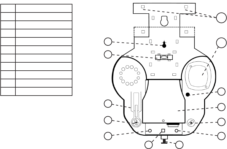
locatIon oF partS
Tamper Return
SAB/SCB
Trigger Signal
Siren Cut-o timer
Only available on the PLUS versions.
In SAB mode (default) the power required to produce the sound is drawn from the security systems control panel. In
SCB mode the power required to produce the sound is drawn from the on-board lithium Ion battery.
It is possible to select 1 of 3 optional times depending on the model being used
The PLUS version and the WIRE-FREE version have either 15minutes (default) 3 minutes or intermittent (50sec ON,
50sec OFF, 50sec ON, 50sec OFF, 50sec ON then stops (times are approximate).
The STANDARD model only has 15minutes (default) or intermittent.
Each model allows you to select the triggering method used to activate the siren and strobe, either Negative 0v
applied (default) or positive +ve applied, depending on the output of the control panel you are using.
Only available on the PLUS and WIRE-FREE versions.
Allows you to select either a Negative signal (default) or a positive signal for the Tamper Return signal to match the
requirements of the control panel being used.
Strobe Saver
After 1 hour of continuous activation the strobe ash rate will be reduced from 1Hz to 0.25Hz
WIRE-FREE version Only
During the installation of the Wire-free version it is possible to check that the best location is selected for the warning
device. Whilst in engineer mode the Green LED will ash to indicate that the warning device is communicating
with the control panel module, if the Green LED stops ashing this indicates that it has lost communication with
the control panel module. Relocate the warning device until the Green LED starts to ash, this indicates that
communication have been re-established.
Communication conrmation
4
7
1
3
2
10
8
9
11
1 Key slot mounting hole
2 Spirit level
3 Tamper protection
4 Swivel Mounting hole
5 Comfort LED
6 Strobe LED
7 Cover xing screw
8 Cover to electronics
9 Cable entry
10 Piezo
11 Hinge bracket for cover
4
5 5
6
X

Page 5 of 16
v3.1
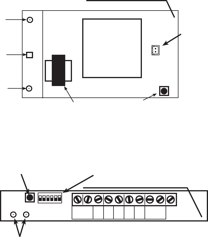
WIred pcB layoutS
+BATT -
Connector
Tamper
Return
Pos +ve
Neg -0v
Con-
Strobe
Siren
Test
Fault
+BATT -
Connector
Charge
LED
Tamper
Return
Pos +ve
Neg -0v
Con-
Strobe
Siren
Test
Fault
pluS
Grade 2 & 3
Standard
Grade 2 only
Tamper
LED
Hold-o
LED
Strobe
LED
Connector
for back-light
PCBA
Connector
for Battery
Sounder
Transformer
Option switches
Connection
Terminals
Battery
Battery
charging
LED
}
Tamper
LED
Hold-o
LED
Strobe
LED
Connector
for Battery
Sounder
Transformer
Option switches
Connection
Terminals
Battery
charging
LED
}
Battery
ON
12345678
ON
1234
Page 6 of 16
v3.1
+BATT -
Connector
Tamper
LED
Coms
LED
Strobe
LED
Sounder
Transformer
Battery
Connector
for Battery
Antenna
Enrolment button
Con-
rmed
Tamper
return
Strobe
Hold O
Pos+
Hold O
Neg-
Test
Siren
Fault
Int
3m
15M
<>>
<<>
N<>P Trig
H<>L Vol
N<>P Tamp
Siren
Antenna
Diagnostic
LEDs
Tamper switch/
Enrolment button
Option switches
Connection
Terminals
}
WIre-Free pcB layoutS
control panel module (cpm)
Grade 2 only
WarnIng devIce (Wd)
Grade 2 only
Green
Red
ON
123456
Page 7 of 16
v3.1
Model
Terminal
Number
Terminal
Name
Description
Plus & CPM 9 Fault
These 2 terminals are normally closed, going open when a fault is
detected.
They also act as a conrmation that the test routine has started by
opening and closing after a successful completion of the test routine.
Plus & CPM 8 Fault
Plus & CPM 7 Test A Positive signal from the control panel to start the test routine LED
Plus & CPM 6 Conrmed
A Negative signal from the control panel to change the Sounder and
Strobe pattern
Plus, standard
& CPM
5
Tamper
Return
A signal from the senza to the control panel to indicate the condition
of the tamper circuit
Plus, standard
& CPM
4 Strobe A signal from the control panel to activate the strobe LED
Plus, standard
& CPM
3 Siren A signal from the control panel to activate the siren LED
Plus, standard
& CPM
2
Hold-o
Positive +ve
A permanent positive DC supply from the control panel
Plus, standard
& CPM
1
Hold-o
Negative 0v
A permanent negative DC supply from the control panel
termInal deScrIptIon
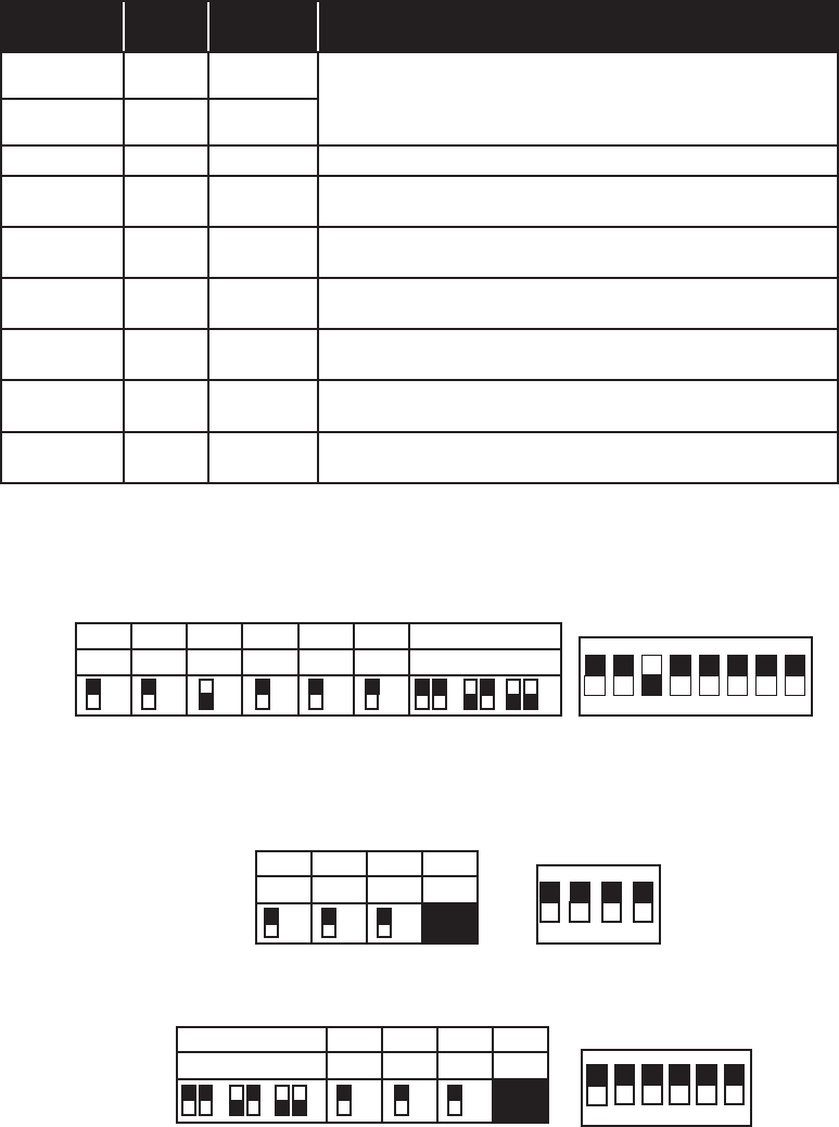
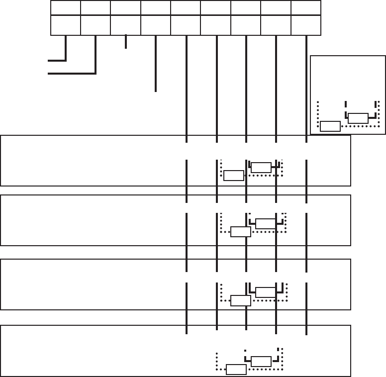
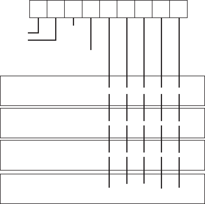
dIp SWItch SettIngS
pluS modelS
Standard modelS
WIre-Free model
1 2 3 4 5 6 7 & 8
Back-light
Tamp
Rtn
SAB/SCB Volume
Trigger
signal
Trigger
Mon
Siren Cut-o timings
ON
ECO
Pos
Neg
SAB
SCB
Lo
Hi
Pos
Neg
ON
OFF
15 3 Int
ON
12345678
Default setting
1 2 3 4
Trigger
signal
Volume
Siren
Timing
Not Used
Pos
Neg
Lo
Hi
Int
15
ON
1234
Default setting
1 & 2 3 4 5 6
Siren Cut-o timings
Trigger
signal
Volume
Tamper
Rtn
Not Used
15 3 Int
Pos
Neg
Lo
Hi
Pos
Neg
Default setting
ON
123456
Page 8 of 16
v3.1
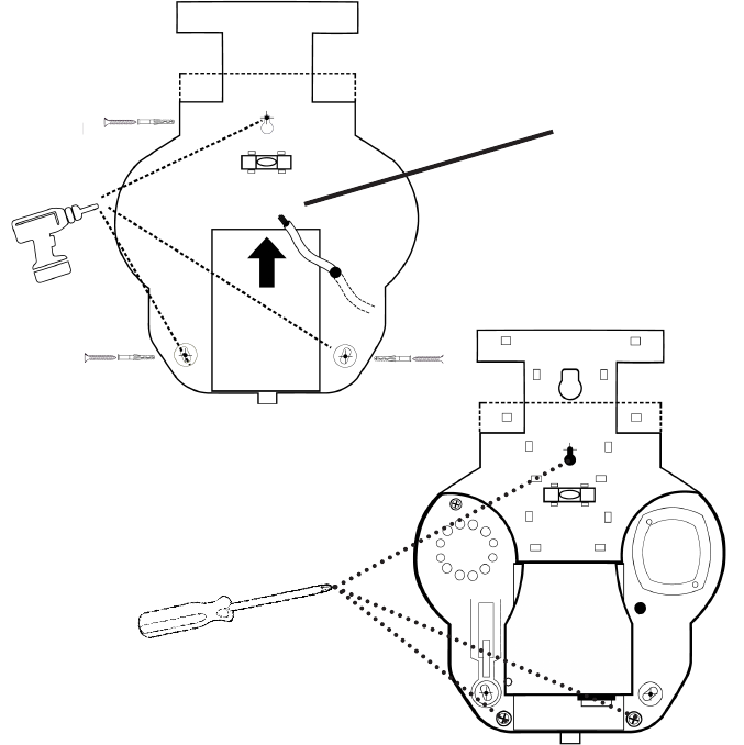
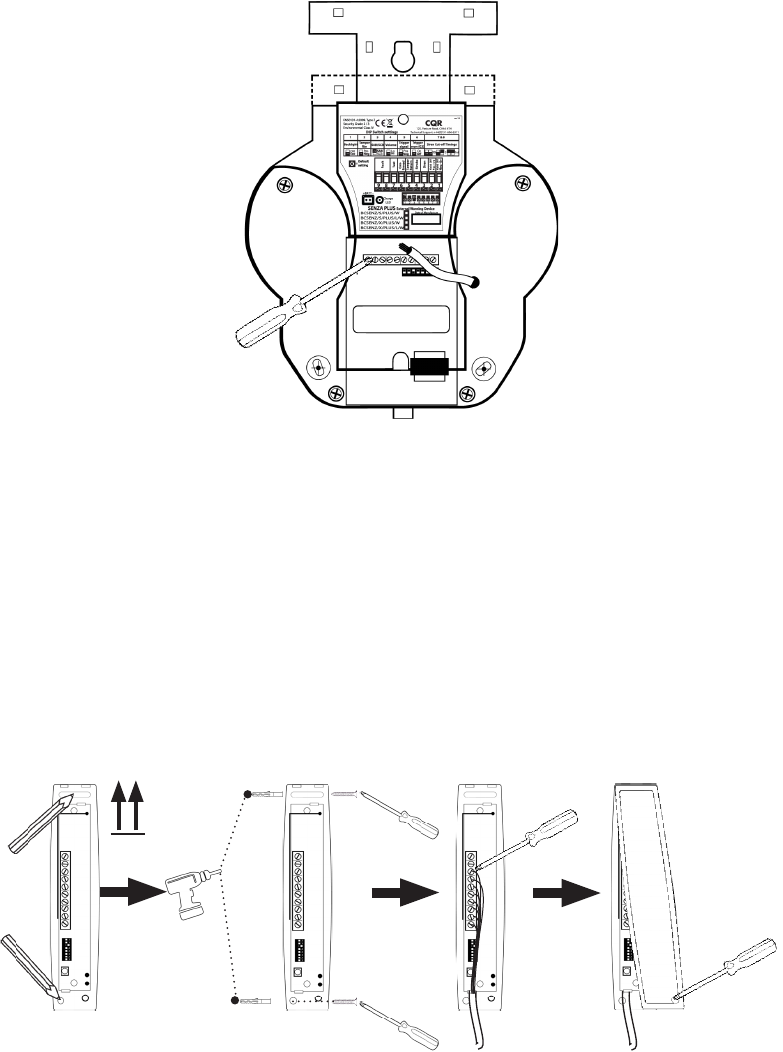
mountIng InStructIonS
Identify a suitable mounting location for the warning device on a at wall. If you are installing the
Wirefree version, you can use the built-in coms feature to locate the best location and ensure the there is
communication between the warning device and the control panel module.
It should not be possible to reach the device without the aid of access equipment, where practical it
should be sited under the eaves to give additional protection.
Mark the xing points on the surface of the selected location using the drill template on the back of the
box. Drill 3 holes using a 5.5mm masonry drill 41mm deep for the enclosed wall plugs, insert the wall
plugs into the holes, t the top centre screw, enclosed, leaving it protruding by 25mm.
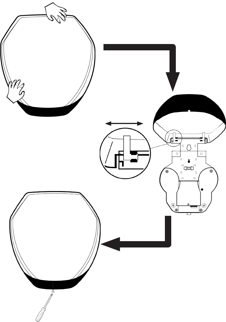
Feed the cable through the cable entry point on the
senza
and carefully slot the top xing point of the
senza
over the previously installed screw, rotate the 2 x bottom xing points, if necessary, to allow the
holes to line up and x in-place using the enclosed screws.
Please note in order for the tamper protection to function correctly one of the mounting screws is
required to be tted in the removal from wall mechanism as shown below. Do not over-tighten this
screw. If forced removal is attempted this will cause irreversible damage and may need replacing.
X
Use the
template on
back of the Box
Page 9 of 16
v3.1
mountIng InStructIonS
control panel model (cpm)
When identifying a suitable mounting location for the CPM, the following points should be noted:
• Do not mount next to an AC source
• Mount away from wireless interference sources (computers, cordless phones, wireless routers, etc.)
• Large metal objects (a distance of 1m is recommended)
Temporarily place the unit in the selected location (do not hold) ensuring that the CPM is vertical,
using the built-in coms feature in the warning device, ensure that there is communication between the
warning device and the CPM see page 12, if not move the location of the CPM and repeat the process.
Mount the CPM in the selected location, connect the CPM to the control panel as shown on page 12.
Ensure CPM
is mounted
Vertical

Page 10 of 16
v3.1
1. Connect Hold-o Neg - 0v to 12v -
2. Connect Hold-o Pos + ve to 12v +
3. Connect Siren to OP BELL
4. Connect Strobe to OP Strobe
5. Connect Tamper Return to an input via a 2K2Ω resistor
1. Connect Hold-o Neg - 0v to D
2. Connect Hold-o Pos + ve to A
3. Connect Siren to B
4. Connect Strobe to S
5. Connect Tamper Return to C
1. Connect Hold-o Neg - 0v to 12v com
2. Connect Hold-o Pos + ve to +12v
3. Connect Siren to BELL
4. Connect Strobe to STRB
5. Connect Tamper Return via a 2K2Ω resistor to D1
1. Connect Hold-o Neg - 0v to 0v
2. Connect Hold-o Pos + ve to 12v
3. Connect Siren to Bell
4. Connect Strobe to STB
5. Connect Tamper Return to TR
Texecom
Pyronix
Honeywell
Scantronic
WIrIng connectIon guIde
1. Ensure that the DIP switches are set to your requirements.
2. Connect the wires to the
senza
as shown below.
3. Plug in the battery and one bleep will be heard.
4. Ensure the tamper switch will close properly and t the lid, two bleeps will be heard.
5. The tamper LED should start to ash twice a second.
6. This will stay like this until hold o voltage is applied or the battery goes at.
7. Connect the control panel as indicated below.
8. Apply power to the
senza.
9. Both the hold-o LED and the tamper LED will now ash. Two bleeps will be heard.
10. After a few seconds the unit will bleep again and the LED’s will ash alternately.
11. After 5 minutes the engineer mode will expire and the LED’s will ash at the normal rate of once per second.
12. The
senza
is now in its normal mode.
Note:- Examples shown below are provided only as a guide, Control panel manufacturers may alter their notation
from time to time and there may be dierences to those shown.
Standard Version
Hold-o
Pos +
SirenStrobe
Tamper
Rtn
Hold-o
Neg -
C AS B D
D1 +12VSTRB BELL
COM
senza ConneCtions
TR +12VSTB BELL
0v
Input 12V
OP
STRB
OP
BELL
12v-
5 4 3 2 1
Page 11 of 16
v3.1
1. Connect Hold-o Neg - 0v to 12v -
2. Connect Hold-o Pos + ve to 12v +
3. Connect Siren to OP BELL
4. Connect Strobe to OP Strobe
5. Connect Tamper Return to an input via a 2K2Ω resistor
1. Connect Hold-o Neg - 0v to D
2. Connect Hold-o Pos + ve to A
3. Connect Siren to B
4. Connect Strobe to S
5. Connect Tamper Return to C
1. Connect Hold-o Neg - 0v to 12v com
2. Connect Hold-o Pos + ve to +12v
3. Connect Siren to BELL
4. Connect Strobe to STRB
5. Connect Tamper Return via a 2K2Ω resistor to D1
1. Connect Hold-o Neg - 0v to 0v
2. Connect Hold-o Pos + ve to 12v
3. Connect Siren to Bell
4. Connect Strobe to STB
5. Connect Tamper Return to TR
WIrIng connectIon guIde
1. Ensure that the DIP switches are set to your requirements.
2. Connect the wires to the
senza
as shown below.
3. Plug in the battery and one bleep will be heard.
4. Ensure the tamper switch will close properly and t the lid, two bleeps will be heard.
5. The tamper LED should start to ash twice a second.
6. This will stay like this until hold o voltage is applied or the battery goes at.
7. Connect the control panel as indicated below.
8. If Trigger wire monitoring is selected the 2 x 1kΩ resistors must be tted prior to power up (G3 requirement).
9. Apply power to the
senza.
10. Both the hold-o LED and the tamper LED will now ash. Two bleeps will be heard.
11. After a few seconds the unit will bleep again and the LED’s will ash alternately.
12. After 5 minutes the engineer mode will expire and the LED’s will ash at the normal rate of once per second.
13. The
senza
is now in its normal mode.
Note:- Examples shown below are provided only as a guide, Control panel manufacturers may alter their notation
from time to time and there may be dierences to those shown.
PLUS Version
Fault Fault Test
Con-
rmed
Hold-o
Pos +
SirenStrobe
Tamper
Rtn
Hold-o
Neg -
C D
D1
COM
Texecom
Pyronix
senza ConneCtions
Honeywell
TR
0v
Input
12v-
Connect to a
suitable input
within the
control panel
Connect to a
suitable output
within the
control panel
Connect to a
suitable output
within the
control panel
1kΩ
1kΩ
1kΩ
1kΩ
1kΩ
1kΩ
1kΩ
1kΩ
AB
+12VBELLSTRB
S
+12VSTB BELL
12V
OP
STRB
OP
BELL
Scantronic
1kΩ
1kΩ
Pull-up resistors
required for trigger
wire monitoring
G3 requirement
9 8 7 6 5 4 3 2 1
Page 12 of 16
v3.1
WIrIng connectIon guIde
Wirefree Version
Fault Fault Test
Con-
rmed
Hold-o
Pos +
SirenStrobe
Tamper
Rtn
Hold-o
Neg -
CPM Connections
Connect to a
suitable input
within the
control panel
Connect to a
suitable output
within the
control panel
1. Connect Hold-o Neg - 0v to 12v -
2. Connect Hold-o Pos + ve to 12v +
3. Connect Siren to OP BELL
4. Connect Strobe to OP Strobe
5. Connect Tamper Return to an input via a 2K2Ω resistor
1. Connect Hold-o Neg - 0v to D
2. Connect Hold-o Pos + ve to A
3. Connect Siren to B
4. Connect Strobe to S
5. Connect Tamper Return to C
1. Connect Hold-o Neg - 0v to 12v com
2. Connect Hold-o Pos + ve to +12v
3. Connect Siren to BELL
4. Connect Strobe to STRB
5. Connect Tamper Return via a 2K2Ω resistor to D1
1. Connect Hold-o Neg - 0v to 0v
2. Connect Hold-o Pos + ve to 12v
3. Connect Siren to Bell
4. Connect Strobe to STB
5. Connect Tamper Return to TR
Texecom
Pyronix
Honeywell
Scantronic
C AS B
D
D1 +12VSTRB BELL
COM
TR +12VSTB BELL
0v
Input
12V
OP
STRB
OP
BELL
12v-
Connect to a
suitable output
within the
control panel
1. Connect the CPM to the control panel as shown in the ‘Senza CPM connections’ below, ensuring that the DIP
switches are set to your requirements. The Green and Red LEDs should ash alternately.
2. Connect the battery in the WD. The CPM and WD should automatically pair. This is indicated by the Green LED on
the WD ashing every 2 seconds. If not refer to Installation and operating instructions on ‘How to pair’.
3. During the next 30 minutes the WD will be in engineer mode, after which it will automatically leave this mode.
Note: if the tamper is still open the sounder will sound.
4. Whilst the WD is in engineer mode the Green LED ashes every 2 seconds to indicate that the WD is
communicating with the CPM.
5. Using this feature will allow you to select the best position for the WD to be installed, if the Green LED stops
ashing it has lost communication with the CPM and should be repositioned.
6. The Blue LED on the WD ashing every 2 seconds indicates that the tamper is closed.
7. To exit Engineer mode briey apply a trigger to the Siren input of the CPM the Strobe will ash once and the
sounder will chirp.
8. Normal operating mode is indicated by the Green and Blue LEDs on the WD ashing alternately every 4 seconds.
Note:- Examples shown below are provided only as a guide, Control panel manufacturers may alter their notation
from time to time and there may be dierences to those shown.
Page 13 of 16
v3.1
FIttIng coverS
Cover
Lock
UnLock
Page 14 of 16
v3.1
operatIng InStructIonS
Please refer to the DIP switch setting on page 7 to setup the device for the conguration you require.
To activate the siren apply an appropriate signal (depending on selection made via the DIP switch) to the
SIREN terminal (3). To deactivate the siren remove the applied signal.
To activate the strobe apply an appropriate signal (depending on selection made via the DIP switch) to
the STROBE terminal (4). To deactivate the strobe remove the applied signal.
During an activation of the Siren and/or Strobe, if a negative signal is applied to the Conrmed Terminal
(6) it will change the Siren tone and/or the Strobe ash rate. Removal of the signal will result in the Siren
tone and/or the Strobe ash rate returning to it normal tone/rate.
If the device’s tamper protection is activated by opening the cover or by forcibly removing the warning
device from the wall, the signal (depending on the selection made via DIP switch) will be removed from
the Tamper Return terminal (5). Closing the cover will result in the signal being restored.
Note: The Senza is designed not to sound when the tamper switch is opened to allow for the installation/
service engineer to access the unit without genterating a sound, however this will depend on the
condition/settings of the control panel it is connected to e.g if the panel is in a set condition the sounder
may sound.
If a positive signal is applied to the Test input (7) it will start the test routine.
If the rechargeable battery is disconnected from the device or is not capable of supplying
power to the device, then the Fault output circuit will open.
The loss of the remote power source to the device will activate the siren for the pre selected time via DIP
switches 7 & 8 on the
Plus
or DIP switch 3 on the
standard.
the
Green
(tamper) and
red
(hold-o) comfort LEDs ash alternately at 1Hz. If the
Green
LED stops
ashing this indicates that the tamper protection for the cover and/or the removal from wall is open. If
the
red
LED stops ashing this indicates that there is no voltage on the Hold-o terminals.
The Red battery LED is illuminated when the battery is healthy. If the LED is extinguished this indicates
that the battery is disconnected or faulty.
Wired models
Please refer to the DIP switch setting on page 7 to setup the device for the conguration you required.
To activate the siren apply an appropriate signal (depending on selection made via the DIP switch) to the
SIREN terminal. To deactivate the siren remove the applied signal.
To activate the strobe apply an appropriate signal (depending on selection made via the DIP switch) to
the STROBE terminal. To deactivate the strobe remove the applied signal.
During an activation of the siren and/or strobe, if a negative signal is applied to the Conrmed Terminal
it will change the siren tone and or the strobe ash rate. Removal of the signal will result in the siren tone
and/or the strobe ash rate returning to it normal tone/rate.
If the device’s tamper protection is activated by opening the cover or by forcibly removing the warning
device from the wall, the signal (depending on the selection made via DIP switch on the CPM) will be
removed from the Tamper Return terminal and the sounder will sound. Closing the cover will result in the
signal being restored and the sounder stopping.
If a positive signal is applied to the Test input it will start the test routine. Failure of the test routine will
result in the fault output staying open.
The battery is monitored every 24hrs and this test checks the condition of the battery by applying a load
to the battery. If the battery fails this test the fault output will open circuit.
the
Green
(coms) and
Blue
(tamper)
comfort LEDs ash alternately every 5 seconds. If the
Blue
LED stops
ashing this indicates that the tamper protection for the cover and/or the removal from wall is open.
If the
Green
LED stops ashing this indicates that there is no communication with the control panel
module.
Wire-free model
Page 15 of 16
v3.1
Hold o voltage: 10-15 vDC (12 vDC nominal)
Current Consumption @ 12 vDC: SAB Mode SCB mode
Quiescent: ~35mA (battery fully charged) ~35mA (battery fully charged)
Back-light ON ~55mA ~55mA
Alarm (Sounder & Strobe): ~300mA ~120mA
Siren: ~175mA ~110mA
Strobe: ~55mA ~55mA
Sounder: Type: Piezo
Acoustic Output: Tone
Sound duration: ≤ 15 minutes, ≤ 3 minutes or intermittent
Sound Output Levels: ~105db(A) @ 1 metre
Triggering Method: -ve applied, +ve applied
Strobe: Type: LED
Flash Rate: ~ 60 per minute
Strobe saver mode: ~ 7 per minute
Triggering Method: -ve applied, +ve applied
Battery: Type: Lithium Ion (rechargeable)
Nominal Voltage: 3.7 volt
Capacity: 2000mAh
LED Indicators: Tamper (GREEN), Hold-o (RED) and Battery charging (RED)
Tamper Detection: Removal from mounting and cover.
StandardS:
EN50131-1: 2006 + A2: 2017 Security Grade: 2/3, Environmental Class: IV
EN50131-4: 2009 Warning device Type: Z
WarnIng devIce (Wd)
Battery : Type: Lithium Manganese Dioxide (non-rechargeable)
Nominal Voltage: 3 volt
Capacity: 4700mAh
Approximate life: ~2 years (depending on the number and duration of activations)
Current Consumption:
Quiescent: ~3.5mA
Alarm (Sounder & Strobe): ~245mA
Sounder: Type: Piezo
Acoustic Output: Tone
Sound duration: ≤ 15 minutes, ≤ 3 minutes or intermittent
Sound Output Levels: ~105db(A) @ 1 metre
Strobe: Type: LED
Flash Rate: ~ 60 per minute
Strobe saver mode: ~ 7 per minute
LED Indicators: Tamper (BLUE), Comms (GREEN)
Tamper Detection: Removal from mounting and cover.
Radio Frequency: 868MHz Narrowband
Communication Distance: 100m (Line of Site)
control panel module (cpm)
Power supply: 10-15vDC (12vDC nominal)
Current Consumption @12vDC:
Quiescent: ~20mA
Alarm (Sounder & Strobe): ~30mA
LED indicators: RED & GREEN used for diagnostics
Tamper Detection: Cover and Removal from mounting
StandardS:
EN50131-1:2006 + A2:2017; Security Grade 2, Environmental Class II(CPM) IV(WD)
EN50131-4:2009; Type W
EN50131-5-3:2017; Grade 2
SpecIFIcatIon
Wired
Wire-free
Page 16 of 16
v3.1
Never remove the cover when the strobe is ashing.
The piezo transformer will be hot during and after sounding. Whilst not directly hazardous, touching it
when hot will cause discomfort and should be avoided.
When the Senza is in an alarm condition, high voltages are present. Before removing the cover, stop the
piezo and strobe from operating.
Failure to observe the following precautions regarding the batteries could lead to danger of heating,
ignition, explosion and leaking of hazardous chemicals.
• Do not throw into a re
• Do not heat
• Do not overcharge
• Do not reverse charge
• Do not attempt to charge the battery used in the wire-free version as it is not rechargeable
• Do not short circuit the battery wires
• Do not disassemble
Always observe local regulations when disposing of a battery.
Plastic bags can suocate, always dispose of packaging carefully.
Order code Description
BCSENZ/S/STD/W Senza S Grade 2 Backplate White
BCSENZ/S/PLUS/W Senza S Grade 2/3 Backplate White
BCSENZ/S/PLUS/L/W Senza S Grade 2/3 Backplate White with Backlight
BCSENZ/S/WF/W Senza S Wirefree Kit White (WD & CPM)
BCSENZ/S/COV/W/B Senza S Cover White with Blue Lens
BCSENZ/S/COV/W/B/L Senza S Cover White with Blue Lens with Backlight Panel
BCSENZ/S/DUM/WH Senza S Dummy Backplate White
BCSENZ/X/STD/W Senza X Grade 2 Backplate White
BCSENZ/X/PLUS/W Senza X Grade 2/3 Backplate White
BCSENZ/X/PLUS/L/W Senza X Grade 2/3 backplate White with Backlight
BCSENZ/X/WF/W Senza X Wirefree Kit (WD & CPM)
BCSENZ/X/COV/W Senza X Cover White
BCSENZ/X/COV/W/L Senza X Cover White with Backlight Panel
BCSENZ/X/DUM/W Senza X Dummy Backplate
BCSENZ/S/WF/WD/W Senza S Wirefree Warning device Backplate (WD)
BCSENZ/X/WF/WD/W Senza X Wirefree Warning device Backplate (WD)
BCSENZ/WF/CPM/WH Senza Wirefree Control Panel Module White (CPM)
SaFety precautIonS
product order codeS
