21
1
CQR Security Ltd. 125, Pasture Road, Moreton, Merseyside. CH46 4TH, United Kingdom
Tel: +44 (0)151 606 1000 Support: +44 (0)151 606 6311 email: info@cqr.co.uk Web http://www.cqr.co.uk
Description
Operating and Installation
Instructions
BCMB Issue 6.1
BCMB/*/STD
BCMB/*/PLUS
External Warning Device.
Versatile design with two models.
Choice of eight covers available.
Up to 115dB(A) sound output.
Selectable trigger wire monitoring.
Selectable high and low sound output.
Selectable timers.
Negative or Positive trigger option.
Specifications
Safety Precautions
Never remove the cover when the strobe is flashing.
Wait 3 minutes after the strobe has stopped flashing before removing the cover.
The piezo transformer wll be hot during and after ounding. Whilst not directly hazardous, touching it when hot
wil cause discomfort and should be avoided.
When the Multibox is in alarm condition, high voltages are present. Before removing the cover, stop the piezo
and strobe from operating.
Failure to observe the following precautions regarding the re-chargeable battery could lead to danger of
heating, ignition, explosion and leaking of hazardous chemicals.
Do not throw into a fire.
Do not heat.
Do not overcharge.
Do not reverse charge.
Do not short circuit the battery wires.
Do not disassemble.
Always observe local regulations when disposing of a battery.
Plastic bags can suffocate, always dispose of packaging carefully.
This self powered external warning device can be installed in security systems up to and
including Grade 2 and Grade 3 (depending on model) Environmental class IV in accordance
with EN50131-1: 2006 + A3: 2020. It is certified by Kiwa to EN50131- 4: 2019, WD type Z.
The warning device features one or two piezos (depending on model) and a strobe for
audible and visual indication of an alarm activation. It is supplemented by a choice of six
stylish covers that are easily attached using one fixing screw. Installer features include
selectable timing options that are model dependant and selectable sound output of
85dB(A) and 115dB(A) measured at 3 metres and 1 meter respectively.
Hold off voltage: 11-15 Vdc (13.6 Vdc nominal)
Current Consumption @ 13.6 Vdc:
Sounder Type: Piezo
Acoustic Output: Tone
Sound duration: ≤ 15 minutes, ≤ 3 minutes or intermittent
Sound Output Levels: ~85db(A) @ 3 metre / ~115db(A) @ 1 metre
Triggering Method: -ve applied, +ve applied or hold off removed
Strobe Type: Xenon
Flash Rate: ~ 60 per minute
Strobe saver mode: ~ 7 per minute
Triggering Method: -ve applied, +ve applied or hold off removed
Rechargeable Battery Type: NiMH
Nominal Voltage: 7.2 volt
Capacity: 330mAh
Interconnections: <30 m
LED Indicators: Tamper and hold off
Tamper (Model dependant): Removal from mounting and screw.
Dimension excluding outer cover: 175mm x 140mm x 65mm
EN50131-1: 2006 +A3:2020
Plus: Grade 3 Environmental Class IV
Std: Grade 2 Environmental Class IV
EN50131-4: 2019
Warning device Type: Z
Multibox Std 85dB (A)
Multibox Std 115dB (A)
Multibox Plus 85db (A)
Multiltibox Plus 115dB (A)
Quiescent Sounder Strobe Total
≤ 40 mA
≤ 40 mA
≤ 40 mA
≤ 40 mA
≤ 40 mA
≤ 40 mA
~20mA
~250mA
~30mA
~15mA
~330mA
~15mA
~190mA
~190mA
~190mA
~190mA
~190mA
~190mA
~160mA
~360mA
~200mA
~200mA
~500mA
~200mA
SAB
SAB
SAB
SAB
SCB
SCB
Denotes Colour
*
Multibox
2 11
Multibox Reference Chart
Whilst every effort has been made to ensure that the contects of this booklet are correct CQR does not
accept liability for loss or damage caused or alledged to have been caused directly or indirectly by this
booklet. CQR Security reserve the right to change the design/ specification of this product and/ or the
contents of this booklet without notice.
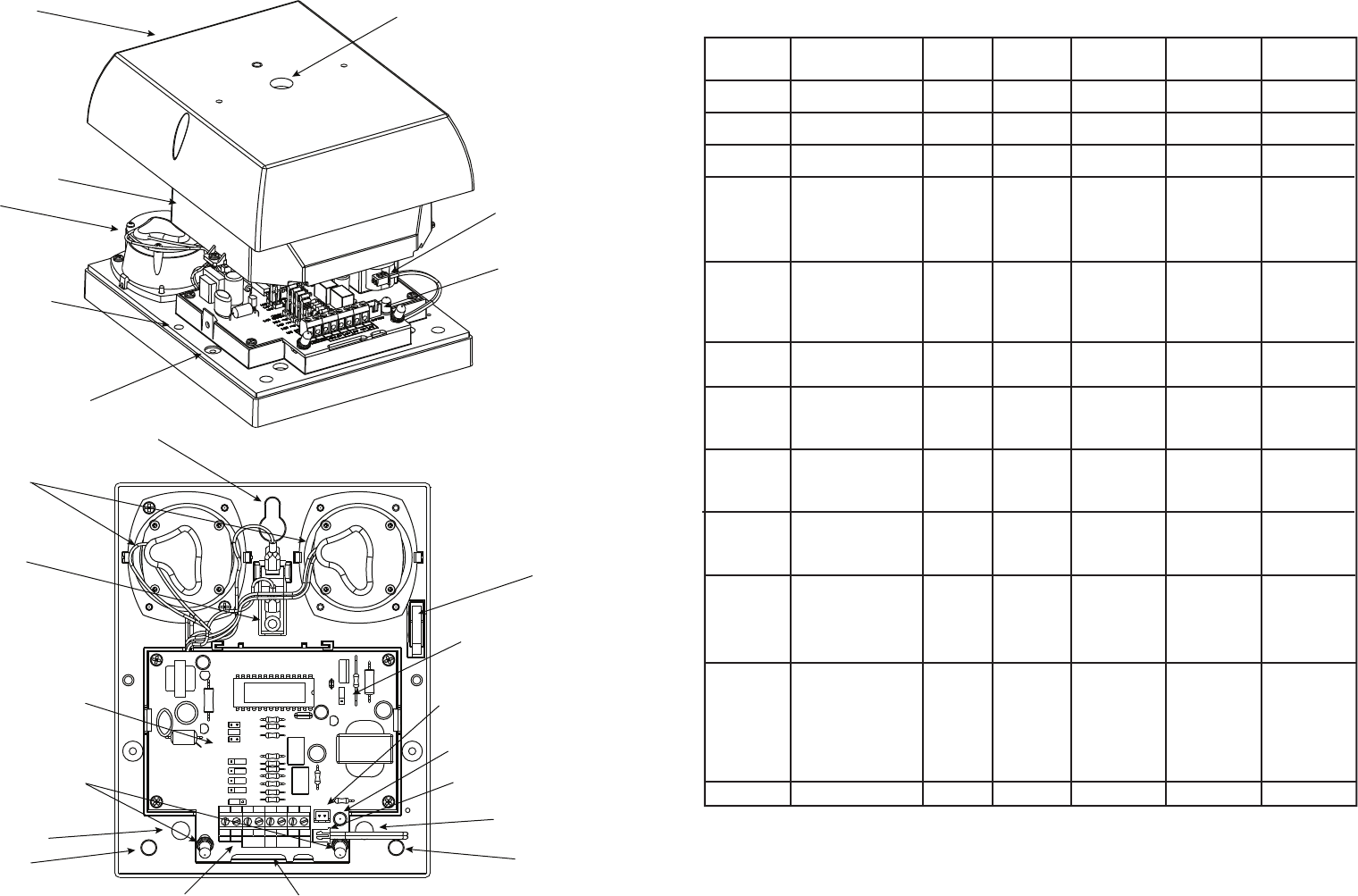
Cover fixing point
Battery connector plug
Battery connector socket
Piezo
Lid fixing point
Inner lid fixing point
Lid
Inner Lid
Fixing point 1
Fixing point 2
Fixing point 3
Lid screw tamper
Battery connector socket
Battery connector plug
Piezo sounders (Model dependant)
Tamper switch
Information LED’s
LK1-LK8 selectors.
Connection terminals
Battery charge LED
LK9 selector
Xenon flash strobe underneath pcb
Cable entry point
Cable entry point
STB
TRIG
HOLD
OFF
-
+
RTN
Fault Fault
TEST
LK1
LK2
LK3
LK4
SAB
+ve
+ve
+ve
SCB
Polarity
-ve
-ve
-ve
STROBE
Disable
LK5
Enable
SIREN
TAMPER RTN
Trigger Wire Monitor
LK6
LK7
LK8
3 Min
15 Min
Intermittent
Siren Timing
BATTERY
Sound output
STD
SPN
LK9
MULTIBOX
ADE
Panels
Ademco
Infra 16
Aritech
Panels
Castle
C & K
DSC
Galaxy
Gardtech
Menvier
Pyronix
Scantronic
Texeco m
2500/1000/15-1700
2700
Omega
ZX1250
800L
700L
703
Active 5
Panel
832
8
60
16
350
370
580/800
400/790/900/2200
TSD402/TS690/TS700
800
Conqueror/ Paragon E
Paragon Plus/ Octogon
Sterling 10
NEW Sterling 10
9448/9800
8136
4600/4500
9100/ 9105
9851
500R
R8
B STROBE- T A D
BELL - STR - BELL TAMP R 0V 12V
EXT BELL STROBE - EOL res TR BHO BELL +
BELL - STR- SAB TAMP HO - HO +
NO / C STR- SAB TAMP HO - HO +
B - STR- ST + return 12V- HO +
EXB- HOLD OFF- HOLD OFF+ST + return
S - ST - R - V - V +
S - ST - R - BELL - BELL +
N0 / COM ST - R - 0V SOUND +
S - ST - 24 TAMPER V - AUX
BELL TRIG STRB TRIG Zone or TAMP HOLD OFF -VE HOLD OFF +VE
BELL - PG2 Z1 AU - BELL +
T HOLD - HOLD +
R101/1 R101/NO T AUX- AUX +
BELL SUN T HOLD - HOLD +
BELL - - STB SCBP SCBA BELL +
BELL - STROBE- SAB TMP BELL HOLD - BELL +
BELL - STROBE- SAB TMP BELL HOLD - BELL +
TRG - STB BELL TAMPER 0V BELL +
TRG - STB - TR - HO - HO +
BELL O/P STRB BELL TMP H/O - H/O +
BA STB BT B/S - B/S +
BA STB BT B - B +
BA STB BT B - B +
NO NO BT BELL - BELL +
BELL STR TR 0V 12V +
OP1 OP2 A/T AUX - VE AUX + VE
BELL NO STR NO TR 0V COM AUX +
NO NO TR 0V 12V
NO NO TR 0V 12V
BELL STR TR 0V 12V
BS C D A
Manufacturer Model Trig STB RTN Hold Off - Hold Off +
01
3
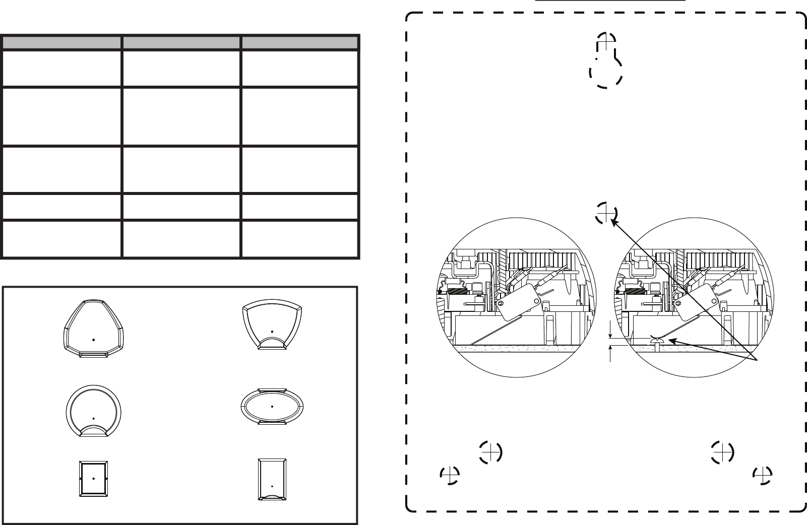
Mounting Instructions
Identify a suitable mounting location for the warning device on a flat wall. It should not be
possible to reach the device without the aid of access equipment, were practical it should be
sited under the eaves to give additional protection. To remove the lid, unscrew the retaining
screws on the each side and carefully remove the lid. Using the template marked on this
page, mark the fixing points on the surface of the selected location. Drill 3 x 8mm holes x 41
mm deep for the enclosed wall plugs, insert the wall plugs into the holes, feed the cable
through the cable entry point on the sounder and using the enclosed screws, fix the sounder
to the selected location.
Please note in order for the tamper protection to conform to grades requiring removal from
mounting protection, a fourth screw is needed under the tamper switch arm as shown below.
Normal Installation
Once the backplate has been mounted, the tamper mechanism should be checked for
correct operation by fitting the lid and if necessary bend the tamper arm to suit. Once this is
complete, the wiring should be carried out in accordance with the next few pages.
Removal from mounting installation.
Screw
7mm
Multibox Diagnostics
SYMPTOM CAUSE REMEDY
Hold-off and tamper
LED’s flash alternately
once per second
Normal operation N/A
Tamper LED flashes twice
per second
Rechargeable battery
connected and the
tamper switch is closed.
No hold-off voltage
present
Apply hold-off voltage
Red battery charging LED
is not illuminated
Rechargeable battery
faulty, damaged or
low charge
Allow the battery to
recharge. Check condtion
of battery and replace if
necessary
Tamper LED not
illuminated
Tamper switch open
Close tamper switch
Hold-off LED not
illuminated
12Vdc not present at
hold-off terminals
Connect 12Vdc to
hold-off terminals, check
fuses in panel
Aries Cover
Taurus Cover
Leo Cover
Corona cover
Libra Cover
Virgo Cover
Fixing point 1
Fixing point 2
Fixing point 3
Tamper
Screw Position
Cable entry point Cable entry point
Available Multibox Covers
295mm x 288mm x 82mm
247mm x 265mm x 75mm
175mm x 140mm x 4mm
235mm x 294mm x 75mm
175mm x 300mm x 75mm
262mm x 178mm x 75mm
(H x W x D)
94
BATTERY
STB
TRIG
HOLD OFF
-
+
RTN
FaultFault
TEST
Trigger Wire Monitor
LK5 Disable
Enable
LK4 +ve
LK3 +ve
LK2 +ve
LK1 SAB
Polarity
SCB
LK8
LK7
LK6
3 Min
15 Min
Intermittent
Siren Timing
LK9
STD SPN
Sound output
-ve
STROBE
-ve
SIREN
TAMPER RTN
-ve
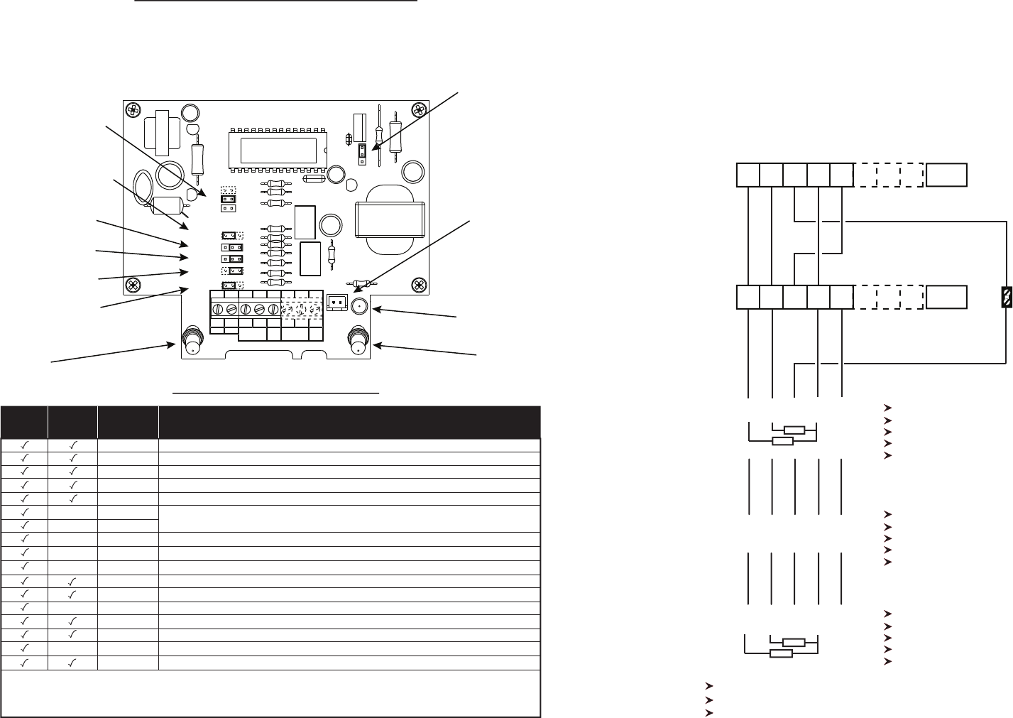
Multibox Circuit Board Layout
MULTIBOX
LK9 Select between
STD 115dB (A) or
SPN 85dB (A)
Battery Socket
Battery charging
indicator LED
LK1 Select SAB/(SCB Mode)
LK2 (Select +ve) or -ve
tamper return
LK3 Select +ve or -ve
siren trigger
LK4 Select +ve or -ve
strobe trigger
LK5 Select Enable/Disable
trigger wire monitoring
LK8 Select (3 minute timer)
LK7 Select 15 minute timer
LK6 Select intermittent timer
Hold off LED
Tamper LED
Terminal Descriptions
(Options in bold italic are on the plus model only)
Quick Set-up Guide
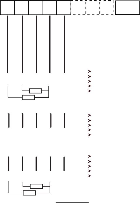
Installing two Multibox units on one system with or without trigger wire monitoring.
1. If trigger wire monitoring is required, ensure that the trigger wire monitoring jumper is in the enabled
position and that two 1K resitors are fitted in the panel where indicated below, if they are required.
2. Connect the five wires between Multibox “1” and “2” as shown. Ensure the wire from the Hold Off -
terminal on Multibox “1” is connected to a terminal block set in Multibox “1” for connection to the
control panel.
3. Connect the batteries, fit the covers to the Multiboxes and then power up the control panel.
Terminal Block
Multibox “1”
Honeywell Panels
Texecom Panels
Scantronic Panels
Connect Hold off + to 12V
Connect Hold off - to 12v-
Connect TRIG(Siren) to OP BELL
Connect STB to OP STRB
Connect RTN to an INPUT via a
2k2Ω resistor
Connect Hold off + to A
Connect Hold off - to D
Connect TRIG(Siren) to B
Connect STB to S
Connect RTN to C
Connect Hold off + to 12v
Connect Hold off - to 0v
Connect TRIG(Siren) to Bell
Connect STB to STB
Connect RTN to TR
Multibox “2”
Check that the red and green LED’s are flashing alternately.
Use the control panel to check the functions of the Multibox.
After aprox 5mins the test mode will expire and the LED’s will speed up.
-+
Plus Only
STB
TRIG
HOLD OFF
-+
RTN
FAULT TESTFAULT
Battery
-+
Plus Only
STB
TRIG
HOLD OFF
-+
RTN
FAULT TESTFAULT
Battery
OP
STRB
12V12v-
OP
BELL
Input
1K
1K
BTSlleB
v21v0
RT
SCDAB
1K
1K
PLUS
Grade 3
STD
Grade 2
Terminal
/Link
Description
Signal from control panel to activate strobe
Signal from control panel to activate siren
Permanent 0v supply from the control panel -ve
Permanent 12vdc supply from the control panel +ve
Tamper return to the control panel
Closed circuit going open during a fault condition
+ve signal from the control panel to activate self test routine
Select SAB/SCB
Select tamper return signal +ve or -ve
Select siren trigger +ve or -ve
Select strobe trigger +ve or -ve
Select trigger wire monitoring Enable or Disable. See Important Note
Intermittant timer
15 minute timer
3 minute timer
Selectable Sound Level: STD = 115dB (A) SPN = 85dB (A). See Important Note
STB
TRIG
HOLD OFF -
HOLD OFF +
RTN
FAULT
FAULT
TEST
LK1
LK2
LK3
LK4
LK5
LK6
LK7
LK8
LK9
X
X
X
X
X
X
X
Note: Default settings are in bold.
Important Note: To comply with Grade 3 requirements, trigger wire monitoring must be enabled, and the sound
level must be set to STD unless national or local variations require a lower dB(A) level.
8 5
Quick Set-up guide.
1. Ensure that the trigger wire monitoring jumper is in the enabled
position.
2. Connect the wires to the Multibox as shown below.
3. Plug in the battery and one bleep will be heard.
4. Ensure the tamper switch will close properly and fit the lid, two bleeps will be heard.
5. The tamper LED should start to flash twice a second. This will stay like this
until hold off voltage is applied or the battery goes flat.
6. Connect the control panel as indicated below and switch on. Two 1 k resistors must be fitted
prior to power up.
7. The hold off LED will now flash with the tamper LED. Two bleeps will be heard.
8. After a few seconds the unit will bleep again and the LED’s will flash alternately.
9. After 5 minutes the engineer mode will expire and the LED’s will flash at the normal
rate of once per second.
* With trigger wire monitoring.
BTS
l
leB
v21v0
RT
SCDAB
Honeywell Panels
Texecom Panels
Scantronic Panels
Connect Hold off + to 12V
Connect Hold off - to 12v-
Connect TRIG(Siren) to OP BELL
Connect STB to OP STRB
Connect
RTN to an Input via a
2k2Ω resistor
Connect Hold off + to A
Connect Hold off - to D
Connect TRIG(Siren) to B
Connect STB to S
Connect RTN to C
Connect Hold off + to 12v
Connect Hold off - to 0v
Connect TRIG(Siren) to Bell
Connect STB to STB
Connect RTN to TR
1K
1K
-+
Plus Only
STB
TRIG
HOLD OFF
-+
RTN
FAULT TESTFAULT
Battery
*Special note
In the event of failure or damage to the trigger wires of the siren or strobe, the Multibox will
indicate by sounder or strobe depending on which one has failed.
1K
1K
Features
Engineer Hold-Off
During the initial connection, it is possible to connect the rechargeable battery without the siren
activating, thus, the siren can be mounted and connected at the same time (one trip up the
ladder) without the need to return to the unit once the hold-off voltage is applied. Please note this
feature is only applicable upon initial installation or if the Multibox has been completely de-powered
i.e. Hold- off supply and the rechargeable battery disconnected.
Engineer Mode
When hold-off voltage has been applied, the unit will first self check, before entering test mode.
This test mode lasts for 5 minutes. During this time, if the sounder is tested, it will sound for 3 or 15
seconds only, depending on which time is selected. This allows testing of the installation without
excessive noise. When the test mode expires the unit will emit a brief sound and the flashing LED’s
will speed up to 1 flash per second.
Strobe Tube Saver
When activated the strobe will flash at 60 flashes per minute for the first hour, after which the
flash rate reduces to 1 every 8 seconds.
Battery Monitor
The rechargeable battery is contantly monitored to determine whether it is no longer able to
power the device in the event of the hold off voltage being removed. Upon installation the battery
monitor may indicate a fault for a few minutes untill the battery has received sufficient charge.
Fault Output
This output signals a failure of the battery. When a failure is detected the normally closed circuit
goes open. When a remote test is started, the fault output opens the circuit which remains open if
a fault is detected and closes if no faults are detected. This output also opens circuits when the
device detects that the siren trigger wire has been removed. (Only if trigger wire monitoring is
enabled)
Test Input
Applying a positive signal from a control panel to this connection will start a local self test proce-
dure.
Options
LK1 SAB/SCB
SAB (Default):- When activated, all power required to operate the siren is drawn from the control
panel
SCB:- When activated, all the power to operate the siren is drawn from the device’ s internal
battery.
LK2 Tamper RTN
Allows you to select either a negative signal (default) or a positive signal for the tamper return
output.
LK3 Siren
Allows you to select the triggering method to activate the siren, either -ve applied (default) or +ve
applied.
LK4 Strobe
Allows you to select the triggering method to activate the strobe, either -ve applied (default) or
+ve applied.
OP
STRB
12V12v-
OP
BELL
Input
76
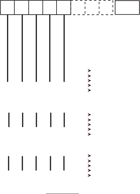
Quick Set-up guide.
1. Ensure that the trigger wire monitoring jumper is in the disabled
position.
2. Connect the wires to the Multibox as shown below.
3. Plug in the battery and one bleep will be heard.
4. Ensure the tamper switch will close properly and fit the lid, two bleeps will be heard.
5. The tamper LED should start to flash twice a second. This will stay like this
until hold off voltage is applied or the battery goes flat.
6. Connect the control panel as indicated below and switch on.
7. The hold off LED will now flash with the tamper LED. Two bleeps will be heard.
8. After a few seconds the unit will bleep again and the LED’s will flash alternately.
9. After 5 minutes the engineer mode will expire and the LED’s will flash at the normal
rate of once per second.
* Without trigger wire monitoring.
BTSlleB
v21v0RT
SCDAB
-+
Plus Only
Honeywell Panels
Texecom Panels
Scantronic Panels
Connect Hold off + to 12V
Connect Hold off - to 12v-
Connect TRIG(Siren) to OP BELL
Connect STB to OP STRB-
Connect RTN to an Input via a
2k2Ω resistor
Connect Hold off + to A
Connect Hold off - to D
Connect TRIG(Siren) to B
Connect STB to S
Connect RTN to C
Connect Hold off + to 12v
Connect Hold off - to 0v
Connect TRIG(Siren) to Bell
Connect STB to STB
Connect RTN to TR
STB
TRIG
HOLD OFF
-+
RTN
FAULT TESTFAULT
*Special note
Please be aware that if trigger wire monitoring is disabled, in the event of failure or damage to the
trigger wires of the siren or strobe, in most cases the control panel will not signal the fact that the
siren and/or strobe are in fact disabled.
Battery
OP
STRB
12V12v-
OP
BELL
Input
Options (continued)
LK5 Trigger Wire Monitoring
This is mandatory for all grade 3 installations. When selected, the device monitors the siren and
strobe trigger wire’s integrity by means of monitoring resistors. These resistors are connected to
opposite signal that is required to activate the siren or strobe i.e. negative siren trigger signal
(default), the monitoring resistor is connected between a positive and trigger wire in the control-
panel. In the event of the siren trigger wire being cut or removed, the fault output circuit will
open, in the event of the strobe trigger wire being cut or removed the strobe will start to flash.
The fault output circuit will NOT be activated.
Note:- Fitting the resistor in the device does not comply with grade 3 requirements.
LK6 Intermittent Timer
When selected the siren will sound for a maximum cycle of 3 times.
50 sec ON, 50 sec OFF, 50 sec ON, 50 sec OFF, 50 sec ON then stops. (times are aproximate).
LK7 15 Min Timer (default)
When selected the siren will sound for a maximum of 15 minutes (times are aproximate).
LK8 3 Min Timer
When selected the siren will sound for a maximum of 3 minutes (times are aproximate)
LK9 Sound Output
Allows selection of the sound output level of either 115dB (A) @1 m (default) or 85 dB (A) @3m
Operating Instructions
Please follow the Set-up guide for instructions on setting up the device for the configuration
required.
• To activate the siren apply an appropriate signal (depending on selected option LK3)
to the TRIG terminal. To deactivate the siren, remove the applied signal.
• To activate the strobe apply an apropriate signal (depending on selected option LK4)
to the STB terminal. To deactivate the strobe, remove the applied signal.
• If the devices tamper protection is activated, the RTN terminal signal (depending on
selected option LK2) will be removed. Deactivating the tamper protection will result in
the terminal being restored.
• If the rechargeable battery is disconnected from the device or is not capable of supply
ing power to the device, in the event of the removal for the remote power source (Plus
model only), the Fault output circuit will open.
• The loss of the remote power source to the device will activate the siren for the time
selected by LK6, LK7 or LK8
