Simulation of die heating for forgings and pressure castings
by convective heating systems
MHI Aritcle # 4 (Further information including Airtorch Catalogs may be
obtained by contacting MHI at 513-772-0404 or 513-672-3333 (fax) or by
email at Airtorch™@mhi-inc.com.)
Abstract
A comparison is made of die temperature uniformity for different heating configurations.
The two situations which are compared are an electric air heater and flame heating.
The temperature uniformity with electric air heating is noted to be substantially superior
to flame heating of large dies. The simulation results are compared with experimentally
obtained numbers and found to be in agreement.
Introduction
The heating of the die is often the most critical start up procedure in forging, extrusion
and pressure die casting operations. Improper pre-heating results in a variety of
problems, the most significant being low die life on account of non-uniform temperature
along the surface of the die (the primary cause for early failure or distortion from
thermal fatigue).
A wide variety of thermal processing techniques are used for die heating. Most
commonly, the dies are heated with one or several gas flame torches. Often, the gas
torches are arranged in a manner so as to produce a distributed heat source on the die
surface. The common problems encountered with this heating method are carbon
deposits, high noise, very significant temperature non-uniformities and a large
temperature difference between the upper and lower die surfaces in vertical
configurations. An alternative to die heating by flames torches, is available with a new
device called the Airtorch™ which is a patented method of electrically heating air or
gasses (1, 2). With the Airtorch™, the problems such as carbon deposits, noise and
explosion hazard conditions are clearly avoided. In this article, we test for the

temperature distribution and uniformity with such a system and compare the uniformity
against flame heating. The use of a similar electrical device has been shown in previous
articles to greatly diminish the power required in low and medium temperature ovens,
enhance the uniformity in oven treated parts, and also completely eliminate distortion
during the heat treating of complex castings (3, 4). Figure 1(a) shows a photograph of
a 3kW, 10kW and 20kW Airtorch™ models.
Figure 1(a): Pictures of a 3, 10 and 20kW Airtorch™ models (counter-clockwise top to
bottom). Picture reproduced with permission from Micropyretics Heaters International.
In this article, die heating by Airtorch™ is simulated by comprehensive computational
fluid dynamic approach and predicted temperatures are compared with experiments.
The air-flow pattern and, in turn, die heating are analyzed. The flame heating is
simulated based on a simplified mathematical assumption model and compared
somewhat with experimental data. Heating patterns of die by air-torch and flame are
compared and reported.
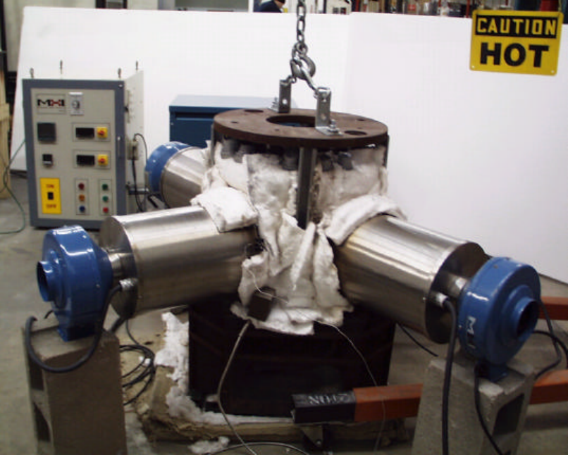
Figure 1(b) A typical configuration for die heating of an aluminum wheel die.
Numerical Simulation of Die Heating
Standard numerical techniques are used to simulate both the cases of die heating by
flame and Airtorch™ heating. Experimental verification of the simulation results by
comparing the temperature and heating rates obtained in complex dies (such as those
shown in Figure 1(b)) is also attempted. The available dies are extremely complex and
so are not simulated exactly except for their overall size and weight. The configuration
considered is the horizontally opposed flat platen assembly commonly used for low
pressure die casting.
A. Modeling of Die Heating by Airtorch™
Two dies of approximately 7500lbs are placed one above the other separated by a
distance of 317.5mm. The dies are provided a heat insulation blanket made of Alumina-
Silicate sheet 1” thick. The heat insulation blanket is held vertically from the top to the
bottom die. The distance between the dies and the heat insulation blanket is 5mm. Hot
air at 25 CFM and 1200°C is directed between the two dies by three Airtorch™ placed
120 degrees apart (Figure 1 (b)). The typical diameter of the Airtorch™ is approximately
254mm. In the present case, the air outlet is provided only close to the the top die
through a narrow passage whereas there is no air outlet at the bottom die.
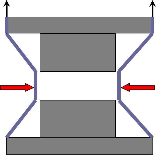
Figure 2: Schematic of die heating by Airtorch™
Air-Outlet
Airtorch™
Airtorch™
Air-Outlet
Die heating by the Airtorch™ is controlled by the thermo-fluid transport in the
surrounding air and by thermal diffusion in the die. The heating of the die by Airtorch™
is governed by 1) the three dimensional Navier-Stokes equations in terms of
conservation of mass, momentum and energy in the space between the two die and 2)
three dimensional conservation equation of energy in the die. A detailed mathematical
representation of the model is presented in the Table I.

Table I
The Model for Heating by Airtorch™
A general conservation equation for all transport variables in a Cartesian
coordinate system is given by:
ΦΦΦ
=
∂
Φ∂
Γ
∂
∂
−
Φ
∂
∂
+
∂
Φ∂
S
xx
u
xt
C
ii
i
i
)(
)(
ρ
ρ
(1)
where
Φ
denotes a general transport variable such as energy,
i
x the
i
-th
Cartesian coordinate,
i
u the
i
-th Cartesian velocity component,
T
the
temperature of the fluid,
ρ
the density of the fluid,
Φ
Γ the diffusivity of
Φ
(dynamic viscosity
µ
or thermal conductivity
λ
), and
Φ
S the source
term of
Φ
(such as heat generation per unit time). Table II gives the
values of
Φ
,
Φ
C ,
Φ
Γ and
Φ
S for all transport equations applied in the
model. Here,
p
C denotes the specific heat at constant pressure. For
simplicity, all equations are given in Cartesian coordinates. However, the
computations were performed on curvilinear boundary-fitted grids.
The boundary conditions:
At the air inlet in three locations 120 degrees apart,
V
in(absolute)
= 25 CFM and T
in
=1200 C (2)
At the heat blanket surface,
Q = 0 and U=V=W= 0 ( no-slip boundary conditions) (3)
At the Air outlet, an outflow boundary condition is specified,
0)( =
i
n
i
dx
dv
dx
d
(4)

Table: II
Transport Variable
Φ
, diffusivity
Φ
Γ and source term
Φ
S for the mass,
momentum and energy equation
Conservation Variable
Φ
Φ
C
Φ
Γ
Φ
S
Mass 1 1 0 0
Momentum
(
j
-th component)
j
u
1
µ
j
x
P
∂
∂
−
Energy
T
p
C
λ
j
i
i
j
j
i
x
u
x
u
x
u
∂
∂
∂
∂
+
∂
∂
µ
Numerical Details
The numerical solution of the governing equations is based on fully conservative finite
volume discretization on non-orthogonal boundary-fitted grids with non-staggered
arrangement of variables. Block structured grids where the grids are globally
unstructured and locally structured, are used and 33507 control volumes are generated
in 33 blocks to discretize the computational domain. Using fully implicit time marching,
the governing equations are solved. Small time-step (1s) is used untill the flow field
reached a quasi-steady state and large time-step (20s) is used beyond time. The
simulations are performed using FASTEST-3D which is a high-performance block-
structured CFD code [6]. Different steps to perform the simulation and optimization of
heating of the die are outlined in the Table III.
Table III
Steps to optimize die heating by Airtorch™
1. Geometric modeling of die assembly.
2. Multi-block grid generation for complete assembly.
3. Applying boundary conditions to solution domain.
4. Specifying Process parameters and Material properties.
5. Specifying Numerical parameters.
6. Numerical Simulation
7. Post processing of results
B. Modeling of Die Heating by Flame
Multiple oxy-acetylene flames at different locations are used in this heating system.
Flame to die heat transfer is extremely complicated involving radiation, convection and
diffusion of flame. A simplified approach is followed in this article to model the flame
heating as outlined below.
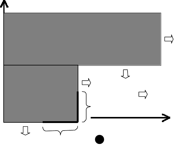
In order to model the thermal transport in the die, a symmetric two-dimensional plane
of the die is considered with flame heating in the corner as shown in Figure 2. The flame
is directly in touch with the surface of the die and the die surface under the flame (i.e.,
S
flame
as shown in the Figure 3) depends on the diameter of the flame, distance of the
torch from the surface as well as the fuel flow rate. The flame heating is modeled by
radiative heat transfer from the flame to the die surface under the flame (S
flame
).
Although the adiabatic temperature of oxy-acetylene flame is 3300°C, there are
significant losses from the flame to ambient and the flame temperature, T
flame
, is
considerably lower than 3300°C. In the modeling approach as describe above, S
flame
and
T
flame
are unknown and these are determined using experimental data of die
temperature. The mathematical model of the flame heating is presented in Table IV.
Figure 3: Modeling of Die Heating by Flame
S
flame
S
flame
The Flame,
T
flame
Convective
Heat Loss

Table IV
The Model for Flame Heating
The governing equation is due to conservation of energy as outlined
below:
0
2
=∇− T
dt
dT
α
(5)
Boundary Conditions
Along S
flame
on the die surface, as shown in the Figure 2, radiative heat
flux is imposed,
0)(
44
=−−
sideflame
TT
A
Q
σε
(6)
From the surface of the die exposed to the ambient, convective heat loss
is In places where heat loss is considered,
0)( =−−
ambientside
TTh
A
Q
(7)
Along the axis of symmetry, Q = 0
The convective heat transfer co-efficient is estimated using standard correlation [5]
1. For Vertical Flat Surfaces
Nu = { 0.825+ (0.387 Ra
1/6
) / [1+(0.492/Pr)
9/16
]
8/27
}
2. For Horizontal flat Surfaces
Nu = 0.27 Ra
1/4
Where Nu, Pr and Ra are Nusselt, Prandtl and Raleigh numbers respectively.
Based on these correlation’s, h
vertical
and h
horizontal
are estimated to
be 8.75 and 3.10 W/m
2
K respectively.
Numerical Details and Fine Tuning:
Using 7500 control volumes, the conservative finite volume equations are solved by fully
implicit time marching and a time-step of 1 second is used for the simulation.
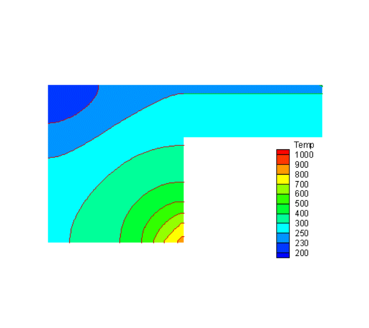
The die temperature near the top surface at 3 mm (approx.) from the top was measured
to be 230°C after 75 minutes of flame heating. Using this data and the materials
properties as presented in Table V, T
flame
and S
flame
are determined to be 1600°C and 6.5
cm respectively and to have a reasonable match between the measurement and
predictions as shown in figure 4. Using these values of T
flame
and S
flame,
die heating by
oxy-acetelene flame is further simulated in this article.
Figure 4. Predicted thermal field in the die after 75 minutes of flame heating

Table V
Material Properties of the Die [4] and Air [5] used in the simulation
Property Die Air
Density 7600 Kg/m
3
0.3166 Kg/m
3
Specific Heat 445 J/kg/K 1159 J/kg/K
Viscosity 449x10
-7
Kg/m/s
Heat Conductivity 60 W/m
2
K 71.5 x 10
-3
W/m
2
K
Emmisivity 0.3
Results and Discussions
In actual die heating practice, the Airtorch™ is placed at an angle to the horizontal plane
depending upon the air-outlet location and the die geometry. In the present study, the
Airtorch™ placement is considered to be without any inclination in order to simplify the
problem. Figure 4 presents isotherms and velocity field in the die-torch assembly at two
cross-sectional planes ( X-X’ and Y-Y’) after two hours of heating as shown in Figure 3.
From the vector plot, a weak flow field can be noted around the sides of the bottom-die
at both the cross-sections. Due to the zero inclination condition of the Airtorch™, the
planar flow field from each Airtorch™ interacts and moves upward towards the outlet as
can be noted in Figure 4. This results in an artificial theoretically low rate of heating in
the lower die. Hence, the thermal field and heating pattern of the top die is considered
for comparison with practical experience as well as for comparing with the simulated
flame heating. Due to the strong flow and mixing, the thermal field around the top die
is noted to be between 600°C and 800°C in the gas and provides a uniform heating
environment.
During heating of a typical medium sized forging die by the Airtorch™ assembly, the
measurements of die temperatures were carried out at different time intervals; typical
values are presented in Table 3. Figures 5 to 7 show the thermal fields in the die at 30
min., 1 hr 30 min. and 2 hrs through the isotherm plot. It is important to note that a
representative die geometry (flat opposing horizontal configuration) is considered
instead of the actual one for the sake of simplicity in the calculations. From Figures 5 to
7 and table VI, it is clearly noted that there is reasonable overall agreement between the

predicted numbers and the measurement. Given the the approximation of the actual die
geometry and Airtorch™, the placement at zero degree inclination, and the overall
agreement in the thermal field clearly establishes validity of the simulation methodology
for such heating.
Table VI
Measured temperature of a die weighing 7500 lbs using three Airtorches™ each with
20 kW power
Time
Hrs Min.
Temperature, C
0 22 135
1 35 200
2 0 220
It is important to note from figures 4-6 that although the maximum thermal gradients
are noted to be between temperatures of 135°C, 200°C and 220°C at 30 min., 1 hr 30
min, and 2 hrs respectively, most of the die surface has a thermal distribution with a
very low temperature gradient. As discussed earlier, the flow field ensures a uniform
heating environment (typically the temperature varies between 600°C and 800°C)
during the entire period of heating; it was noted that the flow field reaches a pseudo
steady state in a very short period from the beginning of the operation and ensures
uniform heating for most the entire period. Such low thermal gradient during the entire
heating period helps to reduce thermal distortion of the die significantly.
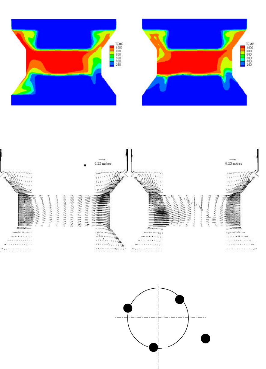
Figure 4. Thermal and flow field in the die-torch assembly at 2 hours of heating
c) Thermal field along Y-Y’
b) Velocity vectors along X-X’ d) Velocity vectors along Y-Y’
a) Thermal field along X-X’
X X’
Y
Y’
The Cross-sectional
Planes of Study
: The Airtorch™
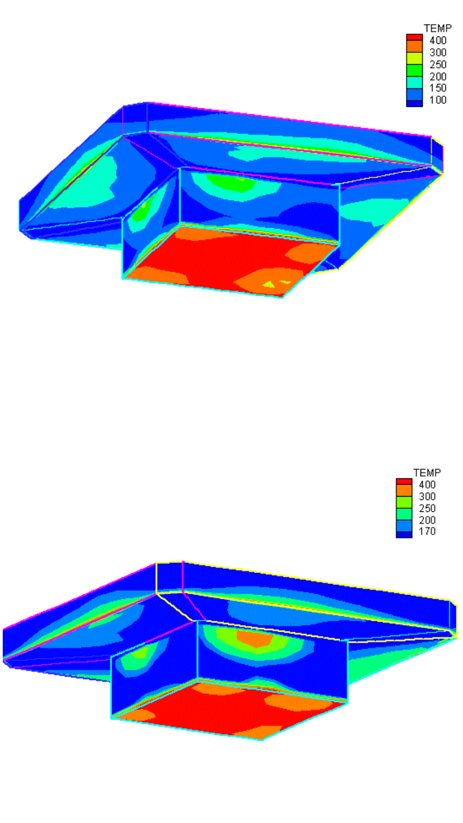
Figure 5. Thermal field in the die after 30 min. of heating by Airtorch™
Figure 6. Thermal field in the die after 1 hr and 30 min. of heating by Airtorch™
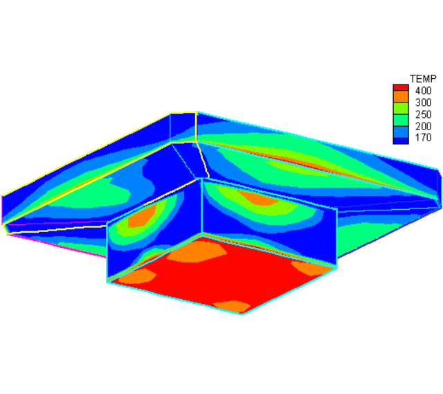
Figure 8 presents a comparative study between flame and Airtorch™ heating of the die.
It can be clearly seen that a very large thermal gradient exists in the die during flame
heating during the entire period of heating. When compared to the uniform heating by
the Airtorch™, we note localized heating by flame resulting in hot-spots as well as a
large thermal gradient as is noted from Figure 8. Additionally, on account of the large
heat loss from the flame and localized heating, the heating efficiency of die by the flame
configuration is considerably lower than that by Airtorch™ which ensures minimal heat
loss.
Summary and Conclusion:
In this article, the heating of a die by both the Airtorch™ and flame are numerically
simulated. A comprehensive approach based on the computational fluid dynamic (CFD)
methods is employed for the Airtorch™ heating simulation. The predicted temperature
of the die surface from the CFD-based modeling of the Airtorch™ heating is shown to be
Figure 7, Thermal field in the die after 2 hrs of heating by Airtorch™
in reasonable agreement with the measured values. Using the CFD simulation as
presented in this paper, the Airtorch™ parameters may be effectively optimized for any
die (for forging and pressure casting) assembly leading to savings in time and cost to
during manufacturing. In addition, the Airtorch™ heating is noiseless and pollution free.
With an air inlet temperature of 1200°C, it is shown that Airtorch™ ensures a near
uniform heating environment of 600°C to 800°C during the entire period of heating of
the die. The temperature in the die does not vary much during the entire period of
heating. In contrast, during flame heating, a high thermal gradient is noted in the die
and additionally there are hot-spots on the surface.
Although the case simulated in this article pertains to heating the die from the cold state
(start-up), the Airtorch™ assembly may be used for “touch up” heating of the die
assembly between runs, in order to bring better uniformity and consistency to the parts
being manufactured.
Further information may be obtained by contacting MHI at 513-772-0404 or 513-672-
3333 (fax) or by email at Airtorch™@mhi-inc.com.
References
1 K. Staples, V. Sarvepalli, M. Fu and J. A. Sekhar, US Patent 5,963, 709 Oct. 5 1999
(see also www.mhi-inc.com)
2 F.H. Jeddy, M. A. Jog, J. A. Sekhar, R. D. Markle, V. Sarvepalli, R. Burada, Advanced
Materials and Processes, Oct, 1999, pg. 13-16
3 J. A. Sekhar, S. Penumella and M. Fu, Novel Heaters for Thermal Processing, eds. R.
Ravindra and R.K. Singh, The Minerals, Metals and Materials Society, 1966, pg. 171-
175
4 M. Fu, K. Staples, V. Sarvepalli, JOM, Vol.50, No.5, May 1988, pg. 42-44
5 Yogesh Jaluria Design and Optimization of thermal Systems .The McGraw – Hill
Companies, INC. International Edition 1998
6 FASTEST-3D, Manual, Invent Computing GmbH, Erlangen, Germany, September
2000.

Nomenclature
T
Temperature
A
Q
Heat Flux
h
Heat transfer Coefficient
ρ
Density
σ
Stefan Boltzman constant
ε
Emissivity
α
Thermal diffusivity
p
c
k
ρ
w
v
u
,
,
Velocities
µ
Viscosity
k
Thermal conductivity
b
Body forces
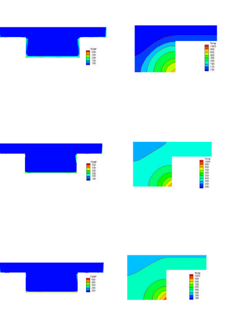
Figure 8, Comparative study of Airtorch™ and Flame heating of die
d) Flame : 30 mins.
e) Flame : 1 hr. 30 min.
f) Flame : 2 hrs
c) Airtorch™ : 2 hrs
a) Airtorch™ : 30 mins.
b) Airtorch™ : 1 hr. 30 mins.
