Heat Exchanger
Design Handbook
Heat Exchanger
Design Handbook
Kuppan Thulukkanam
Second e dition
Thulukkanam
ISBN: 978-1-4398-4212-6
9 781439 842126
9 0 0 0 0
K11966
“One of the most important strengths I noticed after reading Chapter 1 was the
detailed description about the different kinds of heat exchangers. This kind of
description is ideal for students and industry professionals. ... Looking at the
contents and title, the author has made efforts to cover all aspects of heat exchanger
design related to concepts, materials, geometry, fabrication, quality control, and
maintenance. …. I found it extremely useful as a design reference guide for industry
professionals or course textbook for engineering students.”
— RAJEEV MADAZHY, Engineering Manager, Taper-Lok, Sugar Land, TX
Completely revised and updated to reflect current advances in heat exchanger
technology, Heat Exchanger Design Handbook, Second Edition includes enhanced
figures and thermal effectiveness charts, tables, a new chapter, and additional topics—
all while keeping the qualities that made the first edition a centerpiece of information for
practicing engineers, research, engineers, academicians, designers, and manufacturers
involved in heat exchange between two or more fluids.
See What’s New in the Second Edition:
•
Updated information on pressure vessel codes, manufacturer’s
association standards.
•
A new chapter on heat exchanger installation, operation, and
maintenance practices.
•
Classification chapter now includes coverage of scrapped surface,
graphite, coil wound, microscale, and printed circuit heat exchangers.
•
Thorough revision of fabrication of shell and tube heat exchangers,
heat transfer augmentation methods, fouling control concepts and
inclusion of recent advances in PHEs.
New topics like EMbaffle
®
, Helixchanger
®
, and Twisted Tube
®
heat exchanger, feedwater
heater, steam surface condenser, rotary regenerators for HVAC applications, CAB brazing
and cupro-braze radiators.
Without proper heat exchanger design, efficiency of cooling/heating system of plants
and machineries, industrial processes and energy systems can be compromised, and
energy wasted. This thoroughly revised handbook offers comprehensive coverage
of single-phase heat exchangers—selection, thermal design, mechanical design,
corrosion and fouling, FIV, material selection and their fabrication issues, fabrication of
heat exchangers, operation, and maintenance of heat exchangers—all in one volume.
Heat Exchanger
Design Handbook
Heat Exchanger
Design Handbook
Second
e dition
Mechanical engineering
K11966_Cover_mech.indd All Pages 4/22/13 1:12 PM
Heat Exchanger
Design Handbook
SECOND EDITION
MECHANICAL ENGINEERING
A Series of Textbooks and Reference Books
Founding Editor
L. L. Faulkner
Columbus Division, Battelle Memorial Institute
and Department of Mechanical Engineering
The Ohio State University
Columbus, Ohio
RECENTLY PUBLISHED TITLES
Heat Exchanger Design Handbook, Second Edition,
Kuppan Thulukkanam
Vehicle Dynamics, Stability, and Control, Second Edition,
Dean Karnopp
HVAC Water Chillers and Cooling Towers: Fundamentals, Application,
and Operation, Second Edition,
Herbert W. Stanford III
Ultrasonics: Fundamentals, Technologies, and Applications, Third Edition,
Dale Ensminger and Leonard J. Bond
Mechanical Tolerance Stackup and Analysis, Second Edition,
Bryan R. Fischer
Asset Management Excellence,
John D. Campbell, Andrew K. S. Jardine, and Joel McGlynn
Solid Fuels Combustion and Gasication: Modeling, Simulation, and Equipment
Operations, Second Edition, Third Edition,
Marcio L. de Souza-Santos
Mechanical Vibration Analysis, Uncertainties, and Control, Third Edition,
Haym Benaroya and Mark L. Nagurka
Principles of Biomechanics,
Ronald L. Huston
Practical Stress Analysis in Engineering Design, Third Edition,
Ronald L. Huston and Harold Josephs
Practical Guide to the Packaging of Electronics, Second Edition:
Thermal and Mechanical Design and Analysis,
Ali Jamnia
Friction Science and Technology: From Concepts to Applications, Second Edition,
Peter J. Blau
Design and Optimization of Thermal Systems, Second Edition,
Yogesh Jaluria

CRC Press is an imprint of the
Taylor & Francis Group, an informa business
Boca Raton London New York
Heat Exchanger
Design Handbook
Kuppan Thulukkanam
SECOND EDITION
CRC Press
Taylor & Francis Group
6000 Broken Sound Parkway NW, Suite 300
Boca Raton, FL 33487-2742
© 2013 by Taylor & Francis Group, LLC
CRC Press is an imprint of Taylor & Francis Group, an Informa business
No claim to original U.S. Government works
Version Date: 20130204
International Standard Book Number-13: 978-1-4398-4213-3 (eBook - PDF)
This book contains information obtained from authentic and highly regarded sources. Reasonable efforts have been
made to publish reliable data and information, but the author and publisher cannot assume responsibility for the valid-
ity of all materials or the consequences of their use. The authors and publishers have attempted to trace the copyright
holders of all material reproduced in this publication and apologize to copyright holders if permission to publish in this
form has not been obtained. If any copyright material has not been acknowledged please write and let us know so we may
rectify in any future reprint.
Except as permitted under U.S. Copyright Law, no part of this book may be reprinted, reproduced, transmitted, or uti-
lized in any form by any electronic, mechanical, or other means, now known or hereafter invented, including photocopy-
ing, microfilming, and recording, or in any information storage or retrieval system, without written permission from the
publishers.
For permission to photocopy or use material electronically from this work, please access www.copyright.com (http://
www.copyright.com/) or contact the Copyright Clearance Center, Inc. (CCC), 222 Rosewood Drive, Danvers, MA 01923,
978-750-8400. CCC is a not-for-profit organization that provides licenses and registration for a variety of users. For
organizations that have been granted a photocopy license by the CCC, a separate system of payment has been arranged.
Trademark Notice: Product or corporate names may be trademarks or registered trademarks, and are used only for
identification and explanation without intent to infringe.
Visit the Taylor & Francis Web site at
http://www.taylorandfrancis.com
and the CRC Press Web site at
http://www.crcpress.com
Dedicated to
my parents, S. Thulukkanam and T. Senthamarai,
mywife, Tamizselvi Kuppan,
and my mentor, Dr. Ramesh K. Shah

vii
Contents
Preface................................................................................................................................................li
Acknowledgments ........................................................................................................................... liii
Author ...............................................................................................................................................lv
Chapter 1 Heat Exchangers: Introduction, Classication, and Selection ......................................1
1.1 Introduction .......................................................................................................1
1.2 Construction of Heat Exchangers ...................................................................... 1
1.3 Classication of Heat Exchangers ..................................................................... 1
1.3.1 Classication According to Construction ............................................2
1.3.1.1 Tubular Heat Exchanger .......................................................2
1.3.1.2 Plate Heat Exchangers ........................................................ 10
1.3.1.3 Extended Surface Exchangers ............................................ 15
1.3.1.4 Regenerative Heat Exchangers ...........................................15
1.3.2 Classication according to Transfer Process ..................................... 16
1.3.2.1 Indirect Contact Heat Exchangers ...................................... 16
1.3.2.2 Direct Contact–Type Heat Exchangers ............................... 17
1.3.3 Classication according to Surface Compactness.............................. 17
1.3.4 Classication According to Flow Arrangement ................................. 18
1.3.4.1 Parallelow Exchanger ....................................................... 18
1.3.4.2 Counterow Exchanger ......................................................19
1.3.4.3 Crossow Exchanger ..........................................................19
1.3.5 Classication According to Pass Arrangements ................................20
1.3.5.1 Multipass Exchangers .........................................................20
1.3.6 Classication According to Phase of Fluids ...................................... 21
1.3.6.1 Gas–Liquid ......................................................................... 21
1.3.6.2 Liquid–Liquid .....................................................................21
1.3.6.3 Gas–Gas.............................................................................. 21
1.3.7 Classication According to Heat Transfer Mechanisms .................... 21
1.3.7.1 Condensers .......................................................................... 21
1.3.7.2 Evaporators ......................................................................... 21
1.3.8 Other Classications ..........................................................................22
1.3.8.1 Micro Heat Exchanger ........................................................ 22
1.3.8.2 Printed Circuit Heat Exchanger .......................................... 23
1.3.8.3 Perforated Plate Heat Exchanger as Cryocoolers ...............25
1.3.8.4 Scraped Surface Heat Exchanger .......................................25
1.3.8.5 Graphite Heat Exchanger ....................................................27
1.4 Selection of Heat Exchangers .......................................................................... 28
1.4.1 Introduction ........................................................................................28
1.4.2 Selection Criteria ................................................................................29
1.4.2.1 Materials of Construction ................................................... 30
1.4.2.2 Operating Pressure and Temperature .................................30
1.4.2.3 Flow Rate ............................................................................ 31
1.4.2.4 Flow Arrangement .............................................................. 31
1.4.2.5 Performance Parameters: Thermal Effectiveness and
Pressure Drops .................................................................... 31
viii Contents
1.4.2.6 Fouling Tendencies ............................................................. 32
1.4.2.7 Types and Phases of Fluids .................................................32
1.4.2.8 Maintenance, Inspection, Cleaning, Repair, and
Extension Aspects ............................................................... 32
1.4.2.9 Overall Economy ................................................................ 32
1.4.2.10 Fabrication Techniques ....................................................... 33
1.4.2.11 Choice of Unit Type for Intended Applications ..................33
1.5 Requirements of Heat Exchangers ..................................................................34
References ..................................................................................................................34
Suggested Readings ....................................................................................................35
Bibliography ............................................................................................................... 35
Chapter 2 Heat Exchanger Thermohydraulic Fundamentals ......................................................39
2.1 Heat Exchanger Thermal Circuit andOverall Conductance Equation ........... 39
2.2 Heat Exchanger Heat Transfer Analysis Methods ........................................... 41
2.2.1 Energy Balance Equation ................................................................... 41
2.2.2 Heat Transfer ...................................................................................... 41
2.2.3 Basic Methods to Calculate Thermal Effectiveness...........................42
2.2.3.1 ε-NTU Method ................................................................... 42
2.2.3.2 P-NTU
t
Method .................................................................. 43
2.2.3.3 Log Mean Temperature Difference Correction Factor
Method ................................................................................ 45
2.2.3.4 ψ-P Method ........................................................................48
2.2.4 Some Fundamental Relationships to Characterize
theExchanger for “Subdesign” Condition .........................................49
2.3 Thermal Effectiveness Charts .........................................................................50
2.4 Symmetry Property and Flow Reversibility and Relation between
the Thermal Effectiveness of Overall Parallel and Counterow Heat
Exchanger Geometries.....................................................................................52
2.4.1 Symmetry Property ............................................................................ 52
2.4.2 Flow Reversibility .............................................................................. 52
2.5 Temperature Approach, Temperature Meet, and Temperature Cross .............54
2.5.1 Temperature Cross for Other TEMA Shells ......................................56
2.6 Thermal Relation Formulas for Various Flow Arrangements and Pass
Arrangements ..................................................................................................56
2.6.1 Parallelow .........................................................................................57
2.6.2 Counterow ........................................................................................ 57
2.6.3 Crossow Arrangement ......................................................................57
2.6.3.1 Unmixed–Unmixed Crossow ........................................... 57
2.6.3.2 Unmixed–Mixed Crossow ................................................57
2.6.3.3 Mixed–Mixed Crossow .................................................... 57
2.6.3.4 Single or Multiple Rows in Crossow ................................57
2.6.4 Thermal Relations for Various TEMA Shells and Others ................. 72
2.6.4.1 E Shell ................................................................................. 74
2.6.4.2 TEMA F Shell ....................................................................79
2.6.4.3 TEMA G Shell or Split-Flow Exchanger ............................79
2.6.4.4 TEMA H Shell .................................................................... 81
2.6.4.5 TEMA J Shell or Divided-Flow Shell ................................ 81
2.6.4.6 TEMA X Shell ....................................................................90
2.6.5 Thermal Effectiveness of Multiple Heat Exchangers .........................90
ixContents
2.6.5.1 Two-Pass Exchangers .........................................................92
2.6.5.2 N-Pass Exchangers ..............................................................92
2.6.6 Multipass Crossow Exchangers ........................................................92
2.6.6.1 Multipassing with Complete Mixing between Passes ........93
2.6.6.2 Two Passes with One Fluid Unmixed throughout,
Cross-Counterow Arrangement ........................................94
2.6.6.3 Two Passes with Both Fluids Unmixed–Unmixed
inEach Pass and One Fluid Unmixed throughout,
Cross-Counterow Arrangement ........................................98
2.6.6.4 Two Passes with Both Fluids Unmixed throughout,
Cross-Counterow Arrangement ...................................... 101
2.6.7 Thermal Effectiveness of Multiple-Pass Shell and
TubeHeatExchangers ......................................................................108
Acknowledgment ...................................................................................................... 113
References ................................................................................................................ 113
Bibliography ............................................................................................................. 115
Chapter 3 Heat Exchanger Thermal Design ............................................................................. 117
3.1 Fundamentals of Heat Exchanger Design Methodology ............................... 117
3.1.1 Process/Design Specications ......................................................... 117
3.1.1.1 Problem Specication ....................................................... 117
3.1.1.2 Exchanger Construction .................................................... 118
3.1.1.3 Surface Selection .............................................................. 119
3.1.2 Thermohydraulic Design .................................................................. 119
3.1.2.1 Basic Thermohydraulic Design Methods ......................... 119
3.1.2.2 Thermophysical Properties ............................................... 119
3.1.2.3 Surface Geometrical Properties ....................................... 119
3.1.2.4 Surface Characteristics ..................................................... 119
3.2 Design Procedure ..........................................................................................120
3.3 Heat Exchanger Design Problems .................................................................120
3.3.1 Rating ...............................................................................................120
3.3.1.1 Rating of a Compact Exchanger ....................................... 120
3.3.1.2 Rating of a Shell and Tube Exchanger .............................. 121
3.3.2 Sizing ................................................................................................ 121
3.3.2.1 Size of a Heat Exchanger .................................................. 121
3.3.2.2 Sensitivity Analysis .......................................................... 122
3.3.2.3 Sizing of a Compact Heat Exchanger ...............................122
3.3.2.4 Sizing of a Shell and Tube Heat Exchanger ......................122
3.3.2.5 Heat Exchanger Optimization ..........................................122
3.3.3 Solution to the Rating and Sizing Problem ...................................... 122
3.3.3.1 Rating ................................................................................122
3.3.3.2 Solution to the Sizing Problem .........................................123
3.4 Computer-Aided Thermal Design ................................................................. 123
3.4.1 Overall Structure of a Thermal Design Computer Program ............123
3.4.1.1 Guidelines on Program Logic ...........................................124
3.4.2 Program Structure for a Shell and Tube Exchanger ......................... 125
3.5 Pressure-Drop Analysis, Temperature-Dependent Fluid Properties,
Performance Failures, Flow Maldistribution, Fouling, and Corrosion ......... 125
3.5.1 Heat Exchanger Pressure-Drop Analysis ......................................... 125
3.5.1.1 Pressure-Drop Evaluation for Heat Exchangers ...............125
x Contents
3.5.1.2 Pressure Drop through a Heat Exchanger ........................ 126
3.5.1.3 Shell and Tube Heat Exchangers ......................................127
3.5.1.4 Pressure Drop due to Flow Turning..................................127
3.5.1.5 Pressure Drop in the Nozzles ...........................................128
3.5.2 Temperature-Dependent Fluid Properties Correction ......................128
3.5.2.1 Gases ................................................................................. 128
3.5.2.2 Liquids .............................................................................. 129
3.5.3 Performance Failures ....................................................................... 130
3.5.4 Maldistribution ................................................................................. 131
3.5.5 Fouling ............................................................................................. 131
3.5.6 Corrosion Allowance ........................................................................ 132
3.6 Cooperative Research Programs on Heat Exchanger Design ....................... 132
3.6.1 HTRI ................................................................................................ 132
3.6.2 HTFS ................................................................................................ 132
3.7 Uncertainties in Thermal Design of Heat Exchangers .................................. 133
3.7.1 Uncertainties in Heat Exchanger Design ......................................... 133
3.7.1.1 Uncertainty in Process Conditions ................................... 134
3.7.1.2 Uncertainty in the Physical Properties of the Process
Fluids ................................................................................134
3.7.1.3 Flow Nonuniformity ......................................................... 134
3.7.1.4 Nonuniform Flow Passages .............................................. 135
3.7.1.5 Uncertainty in the Basic Design Correlations .................. 135
3.7.1.6 Uncertainty due to Thermodynamically Dened
Mixed or Unmixed Flows for Crossow Heat
Exchangers, after Digiovanni and Webb .......................... 136
3.7.1.7 Nonuniform Heat Transfer Coefcient ............................. 136
3.7.1.8 Bypass Path on the Air Side of Compact Tube-Fin
Exchangers ........................................................................137
3.7.1.9 Uncertainty in Fouling ..................................................... 137
3.7.1.10 Miscellaneous Effects ....................................................... 137
3.7.2 Determination of Uncertainties ........................................................ 137
3.7.2.1 Computational Procedures ............................................... 137
3.7.3.2 Additional Surface Area Required due to Uncertainty .... 139
3.7.3.3 Additional Pressure Drop due to Uncertainty .................. 139
Nomenclature ........................................................................................................... 140
References ................................................................................................................ 141
Bibliography ............................................................................................................. 143
Chapter 4 Compact Heat Exchangers ....................................................................................... 145
4.1 Classication and Construction Details ofTube-Fin Compact Heat
Exchangers ..................................................................................................... 145
4.1.1 Characteristics of Compact Heat Exchangers .................................. 145
4.1.2 Construction Types of Compact Heat Exchangers ........................... 146
4.1.3 Tube-Fin Heat Exchangers ............................................................... 146
4.1.3.1 Specic Qualitative Considerations for Tube-Fin Surfaces .....147
4.1.3.2 Applications ...................................................................... 148
4.1.3.3 Individually Finned Tubes ................................................ 148
4.1.4 Continuous Fins on a Tube Array .................................................... 151
4.1.4.1 Tube: Primary Surface .................................................. 151
4.1.4.2 Fin: Secondary Surface ................................................. 151
xiContents
4.1.4.3 Headers .......................................................................... 152
4.1.4.4 Tube-to-Header Joints ................................................... 152
4.1.4.5 Casings or Tube Frame.................................................. 152
4.1.4.6 Circuiting ...................................................................... 152
4.1.4.7 Exchangers for Air Conditioning and Refrigeration ..... 152
4.1.4.8 Radiators ....................................................................... 153
4.1.4.9 Effect of Fin Density on Fouling .................................. 153
4.1.4.10 One-Row Radiator .......................................................154
4.1.4.11 Manufacture of Continuous Finned Tube Heat
Exchangers .................................................................... 155
4.1.5 Surface Selection .............................................................................. 156
4.1.5.1 Qualitative Considerations ............................................ 156
4.1.5.2 Quantitative Considerations .......................................... 157
4.2 Plate-Fin Heat Exchangers ............................................................................ 157
4.2.1 PFHE: Essential Features ................................................................. 158
4.2.2 Application for Fouling Service ....................................................... 158
4.2.3 Size ................................................................................................... 159
4.2.4 Advantages of PFHEs ...................................................................... 159
4.2.5 Limitations of PFHEs....................................................................... 159
4.2.6 Applications ......................................................................................159
4.2.7 Economics ........................................................................................ 160
4.2.8 Flow Arrangements .......................................................................... 160
4.2.9 Fin Geometry Selection and Performance Factors ..........................160
4.2.9.1 Plain Fin ........................................................................ 160
4.2.9.2 Plain-Perforated Fin ...................................................... 161
4.2.9.3 Offset Strip Fin ............................................................. 162
4.2.9.4 Serrated Fins ................................................................. 163
4.2.9.5 Herringbone or Wavy Fin ............................................. 163
4.2.9.6 Louver Fins ................................................................... 163
4.2.9.7 Pin Fins ......................................................................... 164
4.2.9.8 FIN Corrugation Code .................................................. 165
4.2.10 Corrugation Selection .......................................................................166
4.2.11 Materials of Construction .................................................................166
4.2.11.1 Aluminum ..................................................................... 166
4.2.11.2 Other Metals.................................................................. 166
4.2.12 Mechanical Design ........................................................................... 166
4.2.13 Manufacture, Inspection, and Quality Control ................................ 166
4.2.14 Brazed Aluminum Plate-Fin Heat Exchanger (BAHX) .................. 166
4.2.14.1 ALPEMA Standard ....................................................... 166
4.2.14.2 Applications .................................................................. 169
4.2.14.3 Heat Exchanger Core .................................................... 169
4.2.14.4 Flow Arrangement ........................................................ 169
4.2.14.5 Rough Estimation of the Core Volume ......................... 171
4.2.14.6 Provisions for Thermal Expansion and Contraction ........ 173
4.2.14.7 Mechanical Design of Brazed Aluminum Plate-Fin
Heat Exchangers ............................................................ 173
4.2.14.8 Codes ............................................................................. 173
4.2.14.9 Materials of Construction ............................................. 173
4.2.14.10 Manufacture .................................................................. 174
4.2.14.11 Quality Assurance Program and Third Party
Inspection ...................................................................... 174
xii Contents
4.2.14.12 Testing of BAHX .......................................................... 174
4.2.14.13 Guarantees .................................................................... 174
4.2.14.14 ALEX: Brazed ALuminum EXchanger ....................... 174
4.2.15 Comparison of Salient Features of Plate-Fin Heat Exchangers
and Coil-Wound Heat Exchanger ..................................................... 175
4.2.16 Heat Exchanger Specication Sheet for Plate-Fin Heat Exchanger .........175
4.3 Surface Geometrical Relations ...................................................................... 175
4.3.1 Surface Geometrical Parameters: General ....................................... 175
4.3.1.1 Hydraulic Diameter, D
h
.................................................... 175
4.3.1.2 Surface Area Density α and σ .......................................... 177
4.3.2 Tubular Heat Exchangers ................................................................. 177
4.3.2.1 Tube Inside ........................................................................ 177
4.3.2.2 Tube Outside ..................................................................... 178
4.3.3 Compact Plate-Fin Exchangers ........................................................ 184
4.3.3.1 Heat Transfer Area............................................................ 184
4.3.3.2 Components of Pressure Loss ........................................... 186
4.4 Factors Inuencing Tube-Fin Heat Exchanger Performance ........................ 187
4.4.1 Tube Layout ...................................................................................... 187
4.4.2 Equilateral Layout versus Equivelocity Layout ............................... 187
4.4.3 Number of Tube Rows ...................................................................... 187
4.4.4 Tube Pitch ......................................................................................... 188
4.4.5 Tube-Fin Variables ........................................................................... 188
4.4.5.1 Fin Height and Fin Pitch ................................................... 188
4.4.6 Finned Tubes with Surface Modications........................................ 188
4.4.7 Side Leakage .................................................................................... 189
4.4.8 Boundary-Layer Disturbances and Characteristic Flow Length ..... 189
4.4.9 Contact Resistance in Finned Tube Heat Exchangers ...................... 190
4.4.9.1 Continuous Finned Tube Exchanger .................................190
4.4.9.2 Tension-Wound Fins on Circular Tubes ............................190
4.4.9.3 Integral Finned Tube ......................................................... 190
4.4.10 Induced Draft versus Forced Draft .................................................. 191
4.4.10.1 Induced Draft .................................................................... 191
4.4.10.2 Forced Draft...................................................................... 191
4.5 Thermohydraulic Fundamentalsof Finned Tube Heat Exchangers .............. 191
4.5.1 Heat Transfer and Friction Factor CorrelationsforCrossow
over Staggered Finned Tube Banks .................................................. 191
4.5.2 The j and f Factors ............................................................................192
4.5.2.1 Bare Tube Bank ................................................................ 192
4.5.2.2 Circular Tube-Fin Arrangement ....................................... 193
4.5.2.3 Continuous Fin on Circular Tube ..................................... 196
4.5.2.4 Continuous Fin on Flat Tube Array .................................. 198
4.6 Correlations for j and f factors of Plate-Fin Heat Exchangers ...................... 198
4.6.1 Offset Strip Fin Heat Exchanger ...................................................... 198
4.6.2 Louvered Fin ....................................................................................200
4.6.3 Pin Fin Heat Exchangers .................................................................. 201
4.7 Fin Efciency ................................................................................................202
4.7.1 Fin Length for Some Plate-Fin Heat Exchanger Fin
Congurations ..................................................................................202
4.7.2 Fin Efciency ...................................................................................202
4.7.2.1 Circular Fin .......................................................................202
4.7.2.2 Plain Continuous Fin on Circular Tubes ..........................204
xiiiContents
4.8 Rating of a Compact Exchanger ....................................................................206
4.8.1 Rating of Single-Pass Counterow and Crossow Exchangers ....... 207
4.8.2 Shah’s Method for Rating of Multipass Counterow and
Crossow Heat Exchangers ..............................................................209
4.9 Sizing of a Compact Heat Exchanger ............................................................ 210
4.9.1 Core Mass Velocity Equation ........................................................... 210
4.9.2 Procedure for Sizing a Compact Heat Exchanger ............................ 211
4.9.3 Optimization of Plate-Fin Exchangers andConstraints on
Weight Minimization ....................................................................... 211
4.10 Effect of Longitudinal Heat Conduction on Thermal Effectiveness ............. 212
4.10.1 Longitudinal Conduction Inuence on Various Flow
Arrangements ................................................................................... 213
4.10.2 Comparison of Thermal Performance of Compact Heat
Exchangers ....................................................................................... 213
4.11 Air-Cooled Heat Exchanger (ACHE) ............................................................ 213
4.11.1 Air versus Water Cooling ................................................................. 214
4.11.1.1 Air Cooling ....................................................................... 215
4.11.2 Construction of ACHE ..................................................................... 216
4.11.2.1 Tube Bundle Construction ................................................ 216
4.11.3 American Petroleum Institute Standard API 661/ISO 13706 ..........224
4.11.4 Problems with Heat Exchangers in Low-Temperature Environments .. 225
4.11.4.1 Temperature Control .........................................................225
4.11.5 Forced Draft versus Induced Draft ..................................................225
4.11.5.1 Forced Draft......................................................................225
4.11.5.2 Induced Draft ....................................................................225
4.11.6 Recirculation ....................................................................................226
4.11.7 Design Aspects ................................................................................. 226
4.11.7.1 Design Variables ............................................................... 226
4.11.7.2 Design Air Temperature ...................................................227
4.11.8 Design Tips .......................................................................................228
4.11.8.1 Air-Cooled Heat Exchanger Design Procedure ................228
4.11.8.2 Air-Cooled Heat Exchanger Data/Specication Sheet .....229
4.11.8.3 Performance Control of ACHEs .......................................230
Nomenclature ...........................................................................................................230
References ................................................................................................................232
Bibliography .............................................................................................................236
Chapter 5 Shell and Tube Heat Exchanger Design ................................................................... 237
5.1 Construction Details for Shell and Tube Exchangers .................................... 237
5.1.1 Design Standards .............................................................................. 237
5.1.1.1 TEMA Standard ...............................................................237
5.1.1.2 ANSI/API Standard 660 ................................................... 237
5.2 Tubes ..............................................................................................................238
5.2.1 Tube Diameter .................................................................................. 239
5.2.2 Tube Wall Thickness ........................................................................ 239
5.2.3 Low-Finned Tubes ............................................................................240
5.2.4 Tube Length ......................................................................................240
5.2.5 Means of Fabricating Tubes .............................................................240
5.2.6 Duplex or Bimetallic Tubes ..............................................................240
5.2.7 Number of Tubes .............................................................................. 241
xiv Contents
5.2.8 Tube Count ....................................................................................... 241
5.2.9 U-Tube .............................................................................................. 241
5.2.9.1 U-Tube U-Bend Requirements as per TEMA ................... 241
5.3 Tube Arrangement ......................................................................................... 242
5.3.1 Tube Pitch .........................................................................................242
5.3.2 Tube Layout ...................................................................................... 242
5.3.2.1 Triangular and Rotated Triangular Arrangements ........... 242
5.3.2.2 Square and Rotated Square Arrangements .......................243
5.4 Bafes ............................................................................................................243
5.4.1 Classication of Bafes ....................................................................243
5.4.2 Transverse Bafes ............................................................................243
5.4.2.1 Segmental Bafes ............................................................. 243
5.4.3 Disk and Doughnut Bafe ................................................................247
5.4.4 Orice Bafe .................................................................................... 248
5.4.5 No Tubes in Window ........................................................................ 248
5.4.6 Longitudinal Bafes .........................................................................249
5.4.7 Rod Bafes ....................................................................................... 249
5.4.8 NEST Bafes and Egg-Crate Tube Support .....................................249
5.4.8.1 Non-Segmental Bafes .....................................................250
5.4.9 Grimmas Bafe ................................................................................ 251
5.4.10 Wavy Bar Bafe ............................................................................... 251
5.4.11 Bafes for Steam Generator Tube Support ...................................... 251
5.5 Tubesheet and Its Connection with Shell and Channel ................................. 252
5.5.1 Clad and Faced Tubesheets .............................................................. 253
5.5.2 Tube-to-Tubesheet Attachment.........................................................253
5.5.3 Double Tubesheets ............................................................................253
5.5.3.1 Types of Double Tubesheet Designs .................................253
5.5.4 Demerits of Double Tubesheets........................................................256
5.6 Tube Bundle ...................................................................................................256
5.6.1 Bundle Weight .................................................................................. 256
5.6.2 Spacers, Tie-Rods, and Sealing Devices ..........................................256
5.6.3 Outer Tube Limit .............................................................................. 256
5.7 Shells .............................................................................................................258
5.8 Pass Arrangement ..........................................................................................258
5.8.1 Tubeside Passes ................................................................................ 258
5.8.1.1 Number of Tube Passes .....................................................258
5.8.1.2 End Channel and Channel Cover ......................................260
5.8.2 Shellside Passes ................................................................................262
5.8.2.1 Expansion Joint .................................................................263
5.8.2.2 Drains and Vents ...............................................................263
5.8.2.3 Nozzles and Impingement Protection ...............................263
5.9 Fluid Properties and Allocation ....................................................................266
5.10 Classication of Shell and Tube Heat Exchangers ........................................266
5.11 TEMA System for Describing Heat Exchanger Types ..................................266
5.11.1 Fixed Tubesheet Exchangers ............................................................269
5.11.2 U-Tube Exchangers ...........................................................................270
5.11.2.1 Shortcomings of U-Tube Exchangers ...............................270
5.11.3 Floating Head Exchangers ...............................................................271
5.11.3.1 Sliding Bar/Surface ........................................................... 271
5.11.3.2 Kettle-Type Reboiler .........................................................272
xvContents
5.12 Differential Thermal Expansion ....................................................................272
5.13 TEMA Classication of Heat Exchangers Based on Service Condition ....... 272
5.14 Shell and Tube Heat Exchanger Selection .....................................................272
5.14.1 Shell Types .......................................................................................272
5.14.1.1 TEMA E Shell .................................................................. 274
5.14.1.2 TEMA F Shell .................................................................. 274
5.14.1.3 TEMA G, H Shell ............................................................. 275
5.14.1.4 TEMA G Shell or Split Flow Exchanger .......................... 275
5.14.1.5 TEMA H Shell or Double Split Flow Exchanger .............275
5.14.1.6 TEMA J Shell or Divided Flow Exchanger .....................276
5.14.1.7 TEMA K Shell or Kettle Type Reboiler ........................... 276
5.14.1.8 TEM X Shell ..................................................................... 277
5.14.1.9 Comparison of Various TEMA Shells .............................. 278
5.14.2 Front and Rear Head Designs ..........................................................278
5.14.2.1 Designations for Head Types ............................................278
5.14.3 TEMA Specication Sheet ............................................................... 279
5.15 Shellside Clearances ......................................................................................279
5.15.1 Tube-to-Bafe-Hole Clearance ........................................................ 279
5.15.2 Shell-to-Bafe Clearance ................................................................. 279
5.15.3 Shell-to-Bundle Clearance ...............................................................279
5.15.4 Bypass Lanes ....................................................................................282
5.16 Design Methodology .....................................................................................282
5.16.1 Shellside Flow Pattern ......................................................................282
5.16.1.1 Shell Fluid Bypassing and Leakage .................................282
5.16.1.2 Bypass Prevention and Sealing Devices ...........................282
5.16.1.3 Shellside Flow Pattern ......................................................284
5.16.1.4 Flow Fractions for Each Stream .......................................285
5.16.1.5 Shellside Performance ......................................................285
5.16.2 Sizing of Shell and Tube Heat Exchangers ......................................285
5.16.3 Guidelines for STHE Design............................................................285
5.16.3.1 Heat Transfer Coefcient and Pressure Drop ................... 286
5.16.4 Guidelines for Shellside Design .......................................................286
5.16.4.1 Specify the Right Heat Exchanger....................................287
5.16.5 Design Considerations for a Shell and Tube Heat Exchanger .......... 287
5.16.5.1 Thermal Design Procedure ...............................................288
5.16.5.2 Detailed Design Method: Bell–Delaware Method ........... 291
5.16.5.3 Auxiliary Calculations, Step-by-Step Procedure .............293
5.16.6 Shellside Heat Transfer and Pressure-Drop Correction Factors ......297
5.16.6.1 Step-by-Step Procedure to Determine Heat Transfer
and Pressure-Drop Correction Factors .............................298
5.16.6.2 Shellside Heat Transfer Coefcient and Pressure Drop .......301
5.16.6.3 Tubeside Heat Transfer Coefcient and Pressure Drop ...........304
5.16.6.4 Accuracy of the Bell–Delaware Method ..........................308
5.16.6.5 Extension of the Delaware Method to Other Geometries .........308
5.17 Shell and Tube Heat Exchangers with Non-Segmental Bafes .................... 310
5.17.1 Phillips RODbafe Heat Exchanger................................................. 310
5.17.1.1 RODbafe Exchanger Concepts ....................................... 310
5.17.1.2 Important Benet: Elimination of Shellside
Flow-Induced Vibration .................................................... 311
5.17.1.3 Proven RODbafe Applications ....................................... 311
xvi Contents
5.17.1.4 Operational Characteristics .............................................. 311
5.17.1.5 Thermal Performance ....................................................... 311
5.17.1.6 Design and Rating Program Available ............................. 312
5.17.2 EMbafe
®
Heat Exchanger .............................................................. 312
5.17.2.1 Application of EMbafe Technology ............................... 312
5.17.2.2 Design ............................................................................... 312
5.17.2.3 Benets of EMbafe Technology ..................................... 314
5.17.3 Helixchanger
®
Heat Exchanger ........................................................ 314
5.17.3.1 Merits of Helixchanger Heat Exchanger ........................... 315
5.17.3.2 Applications ...................................................................... 315
5.17.3.3 Helixchanger Heat Exchanger: Congurations ................ 315
5.17.3.4 Performance ...................................................................... 317
5.17.4 Twisted Tube
®
Heat Exchanger ........................................................ 318
5.17.4.1 Applications ...................................................................... 318
5.17.4.2 Advantages ........................................................................ 318
5.17.4.3 Merits of Twisted Tube Heat Exchanger ........................... 319
5.17.5 End Closures .................................................................................... 319
5.17.5.1 Breech-Lock™ Closure .................................................... 319
5.17.5.2 Easy Installation and Dismantling Jig .............................. 320
5.17.6 Taper-Lok
®
Closure ..........................................................................320
5.17.7 High-Pressure End Closures ............................................................320
5.A Appendix A ................................................................................................... 321
5.A.1 Reference Crossow Velocity as per Tinker .................................... 321
5.A.2 Design of Disk and Doughnut Heat Exchanger ...............................323
5.A.2.1 Design Method..................................................................323
5.A.2.2 Heat Transfer ....................................................................324
5.A.2.3 Shellside Pressure Drop ....................................................326
5.A.2.4 Shortcomings of Disk and Doughnut Heat Exchanger .....326
5.A.3 NORAM RF™ Radial Flow Gas Heat Exchanger ..........................326
5.A.3.1 Tube Layout ......................................................................327
5.A.4 Closed Feedwater Heaters ................................................................ 327
5.A.4.1 Low-Pressure Feedwater Heaters .....................................328
5.A.4.2 High-Pressure Feedwater Heaters ....................................328
5.A.5 Steam Surface Condenser ................................................................ 329
5.A.5.1 Mechanical Description ....................................................330
5.A.5.2 Parts of Condenser ............................................................330
5.A.5.3 Condenser Tube Material .................................................. 331
5.A.5.4 Condenser Support Systems ............................................. 332
Nomenclature ........................................................................................................... 332
References ................................................................................................................ 333
Suggested Readings .................................................................................................. 336
Chapter 6 Regenerators ............................................................................................................. 337
6.1 Introduction ...................................................................................................337
6.1.1 Regeneration Principle ..................................................................... 337
6.1.2 Regenerators in Thermodynamic Systems and Others .................... 337
6.1.3 Gas Turbine Cycle with Regeneration .............................................. 337
6.1.4 Waste Heat Recovery Application ....................................................338
6.1.5 Benets of Waste Heat Recovery ..................................................... 338
6.1.5.1 Direct Benets .................................................................. 338
xviiContents
6.1.5.2 Indirect Benets ................................................................ 339
6.1.5.3 Fuel Savings due to Preheating Combustion Air .............. 339
6.2 Heat Exchangers Used for Regeneration ....................................................... 339
6.2.1 Recuperator ...................................................................................... 339
6.2.1.1 Merits of Recuperators ..................................................... 339
6.2.2 Regenerator.......................................................................................340
6.2.3 Types of Regenerators ......................................................................340
6.2.4 Fixed-Matrix or Fixed-Bed-Type Regenerator ................................. 341
6.2.4.1 Fixed-Matrix Surface Geometries ....................................342
6.2.4.2 Size ...................................................................................342
6.2.4.3 Merits of Fixed-Bed Regenerators ....................................342
6.2.5 Rotary Regenerators .........................................................................343
6.2.5.1 Salient Features of Rotary Regenerators ..........................343
6.2.5.2 Rotary Regenerators for Gas Turbine Applications ..........345
6.2.5.3 Types of Rotary Regenerators ..........................................345
6.2.5.4 Drive to Rotary Regenerators ........................................... 345
6.2.5.5 Operating Temperature and Pressure ............................... 345
6.2.5.6 Surface Geometries for Rotary Regenerators ................... 345
6.2.5.7 Inuence of Hydraulic Diameter on Performance............345
6.2.5.8 Size ...................................................................................346
6.2.5.9 Desirable Characteristics for a Regenerative Matrix ........346
6.2.5.10 Total Heat Regenerators ....................................................346
6.2.5.11 Merits of Regenerators ...................................................... 347
6.3 Rotary Regenerative Air Preheater ...............................................................347
6.3.1 Design Features ................................................................................ 348
6.3.2 Heating Element Proles ..................................................................349
6.3.3 Enameled Elements .......................................................................... 349
6.3.4 Corrosion and Fouling ......................................................................349
6.3.5 Heat Exchanger Baskets ................................................................... 349
6.3.6 Seals and Sealing System Components ............................................350
6.3.6.1 Radial Seals and Sector Plates .......................................... 350
6.3.6.2 Axial Seals and Sealing Plates ......................................... 351
6.3.6.3 Circumferential Seals and Circumferential Sealing
Ring ..............................................................................351
6.3.7 Leakage ............................................................................................ 351
6.3.8 Alstom Power Trisector Ljungström
®
Air Preheater ........................ 351
6.4 Comparison of Recuperators and Regenerators ............................................ 352
6.5 Considerations in Establishing a Heat Recovery System .............................. 352
6.5.1 Compatibility with the Existing Process System ............................. 352
6.5.2 Economic Benets ............................................................................ 353
6.5.2.1 Capital Costs ..................................................................... 353
6.5.3 Life of the Exchanger ....................................................................... 353
6.5.4 Maintainability ................................................................................. 353
6.6 Regenerator Construction Material ............................................................... 353
6.6.1 Strength and Stability at the Operating Temperature ......................354
6.6.2 Corrosion Resistance ........................................................................ 355
6.6.3 Ceramic Heat Exchangers ................................................................ 355
6.6.3.1 Low Gas Permeability ...................................................... 355
6.6.4 Ceramic–Metallic Hybrid Recuperator ............................................ 355
6.6.5 Regenerator Materials for Other than Waste Heat Recovery ........... 355
xviii Contents
6.7 Thermal Design: Thermal-Hydraulic Fundamentals .................................... 356
6.7.1 Surface Geometrical Properties ....................................................... 356
6.7.2 Correlation for j and f ....................................................................... 357
6.8 Thermal Design Theory ................................................................................ 358
6.8.1 Regenerator Solution Techniques ..................................................... 359
6.8.1.1 Open Methods: Numerical Finite-Difference Method ..... 359
6.8.1.2 Closed Methods ................................................................ 359
6.8.2 Basic Thermal Design Methods ....................................................... 359
6.8.3 Coppage and Longon Model for a Rotary Regenerator ...................360
6.8.3.1 Thermal Effectiveness ...................................................... 362
6.8.3.2 Heat Transfer ....................................................................364
6.8.4 Parameter Denitions .......................................................................364
6.8.5 Classication of Regenerator............................................................365
6.8.6 Additional Formulas for Regenerator Effectiveness ........................365
6.8.6.1 Balanced and Symmetric Counterow Regenerator ........366
6.8.7 Reduced Length–Reduced Period (Λ–Π) Method ........................... 367
6.8.7.1 Counterow Regenerator .................................................. 367
6.8.8 Razelos Method for Asymmetric-Unbalanced Counterow
Regenerator....................................................................................... 370
6.8.9 Inuence of Longitudinal Heat Conduction in the Wall .................. 371
6.8.9.1 Bahnke and Howard Method ............................................ 372
6.8.9.2 Romie’s Solution ............................................................... 372
6.8.9.3 Shah’s Solution to Account for the Longitudinal
Conduction Effect ............................................................. 373
6.8.10 Fluid Bypass and Carryover on Thermal Effectiveness ................... 374
6.8.11 Regenerator Design Methodology .................................................... 374
6.8.12 Primary Considerations Inuencing Design .................................... 374
6.8.13 Rating of Rotary Regenerators ......................................................... 374
6.8.14 Sizing of Rotary Regenerators ......................................................... 374
6.9 Mechanical Design ........................................................................................ 375
6.9.1 Single-Bed and Dual-Bed Fixed Regenerators ................................ 375
6.9.2 Rotary Regenerators ......................................................................... 375
6.9.2.1 Leakages ........................................................................... 375
6.9.2.2 Seal Design ....................................................................... 376
6.9.2.3 Drive for the Rotor ............................................................376
6.9.2.4 Thermal Distortion and Transients ...................................377
6.9.2.5 Pressure Forces ................................................................. 377
6.10 Industrial Regenerators and Heat Recovery Devices .................................... 377
6.10.1 Fluid-Bed Regenerative Heat Exchangers ........................................ 377
6.10.2 Fluidized-Bed Waste Heat Recovery ............................................... 378
6.10.3 Vortex-Flow Direct-Contact Heat Exchangers .................................379
6.10.4 Ceramic Bayonet Tube Heat Exchangers ......................................... 379
6.10.5 Regenerative Burners .......................................................................379
6.10.6 Porcelain-Enameled Flat-Plate Heat Exchangers .............................380
6.10.7 Radiation Recuperators ....................................................................380
6.10.8 Heat-Pipe Heat Exchangers .............................................................. 381
6.10.8.1 Merits of Heat-Pipe Heat Exchanger ................................ 382
6.10.8.2 Application........................................................................382
6.10.9 Economizer ......................................................................................382
6.10.10 Thermocompressor ...........................................................................382
6.10.11 Mueller Temp-Plate
®
Energy Recovery Banks ................................ 383
xixContents
6.11 Rotary Heat Exchangers for Space Heating .................................................. 383
6.11.1 Working Principle ............................................................................384
6.11.2 Construction .....................................................................................385
6.11.3 Rotor Materials .................................................................................385
6.11.3.1 Construction ......................................................................385
6.11.3.2 Carryover .......................................................................... 385
6.11.3.3 Seals .................................................................................. 385
6.11.4 Drive System and Control Unit ........................................................ 386
6.11.5 Cleaning Devices .............................................................................386
Nomenclature ...........................................................................................................386
References ................................................................................................................388
Bibliography ............................................................................................................. 391
Chapter 7 Plate Heat Exchangers and Spiral Plate Heat Exchangers ....................................... 393
7.1 Plate Heat Exchanger Construction: General ................................................393
7.1.1 Flow Patterns and Pass Arrangement ..............................................394
7.1.2 Useful Data on PHE ......................................................................... 396
7.1.3 Standard Performance Limits ..........................................................397
7.2 Benets Offered by Plate Heat Exchangers ...................................................397
7.3 Comparison between a Plate Heat Exchanger and a Shell and Tube Heat
Exchanger ...................................................................................................... 399
7.4 Plate Heat Exchanger: Detailed Construction Features ................................399
7.4.1 Plate .................................................................................................. 399
7.4.1.1 Plate Pattern ...................................................................... 399
7.4.1.2 Types of Plate Corrugation ...............................................400
7.4.1.3 Intermating Troughs Pattern .............................................400
7.4.1.4 Chevron or Herringbone Trough Pattern ..........................400
7.4.1.5 Plate Materials ..................................................................400
7.4.2 Gasket Selection ...............................................................................400
7.4.3 Bleed Port Design .............................................................................400
7.4.4 Frames ..............................................................................................402
7.4.5 Nozzles .............................................................................................402
7.4.6 Tie Bolts ...........................................................................................402
7.4.7 Connector Plates ...............................................................................403
7.4.8 Connections ...................................................................................... 403
7.4.9 Installation ........................................................................................403
7.5 Brazed Plate Heat Exchanger ........................................................................403
7.6 Other Forms of Plate Heat Exchangers .........................................................403
7.6.1 All-Welded Plate Exchangers ........................................................... 403
7.6.2 Supermax
®
and Maxchanger
®
Plate Heat Exchangers ..................... 404
7.6.3 Wide-Gap Plate Heat Exchanger ......................................................406
7.6.4 GEABloc Fully Welded Plate Heat Exchanger ................................407
7.6.5 Free-Flow Plate Heat Exchanger ......................................................407
7.6.6 Flow-Flex Tubular Plate Heat Exchanger.........................................407
7.6.7 Semiwelded or Twin-Plate Heat Exchanger .....................................409
7.6.8 Double-Wall Plate Heat Exchanger .................................................. 411
7.6.9 Diabon F Graphite Plate Heat Exchanger ........................................ 411
7.6.10 Glue-Free Gaskets (Clip-On Snap-On Gaskets) .............................. 411
7.6.11 AlfaNova 100% Stainless Steel Plate Heat Exchanger .................... 412
7.6.12 Plate Heat Exchanger with Electrode Plate ........................................... 412
xx Contents
7.6.13 Plate Heat Exchanger with Flow Rings ............................................ 412
7.6.14 AlfaRex
™
Gasket-Free Plate Heat Exchanger .................................. 412
7.6.15 Alfa Laval Plate Evaporator ............................................................. 413
7.6.16 Sanitary Heat Exchangers ................................................................ 413
7.6.17 EKasic
®
Silicon Carbide Plate Heat Exchangers ............................. 413
7.6.18 Deep-Set Gasket Grooves ................................................................ 413
7.7 Where to Use Plate Heat Exchangers ............................................................ 413
7.7.1 Applications for Which Plate Heat Exchangers Are Not
Recommended .................................................................................. 413
7.8 Thermohydraulic Fundamentals of Plate Heat Exchangers .......................... 414
7.8.1 High- and Low-Theta Plates ............................................................. 415
7.8.2 Thermal Mixing ............................................................................... 416
7.8.2.1 Thermal Mixing Using High- and Low-Theta Plates ....... 416
7.8.2.2 Thermal Mixing Using Horizontal and
VerticalPlates ........................................................... 416
7.8.3 Flow Area ......................................................................................... 417
7.8.4 Heat Transfer and Pressure-Drop Correlations ................................ 419
7.8.4.1 Heat Transfer Correlations ................................................ 419
7.8.4.2 Pressure Drop ...................................................................420
7.8.5 Specic Pressure Drop or Jensen Number ....................................... 421
7.9 PHE Thermal Design Methods ..................................................................... 421
7.9.1 LMTD Method due to Buonopane et al. .......................................... 422
7.9.2 ε-NTU Approach ..............................................................................422
7.9.3 Specication Sheet for PHE ............................................................. 423
7.9.3.1 Design Pressure ................................................................ 423
7.9.3.2 Plate Hanger ......................................................................424
7.10 Corrosion of Plate Heat Exchangers ..............................................................424
7.11 Fouling ........................................................................................................... 425
7.12 Limitations of Plate Heat Exchangers ...........................................................425
7.13 Spiral Plate Heat Exchangers ........................................................................425
7.13.1 Flow Arrangements and Applications ..............................................426
7.13.2 Construction Material ......................................................................426
7.13.3 Thermal Design of Spiral Plate Heat Exchangers ............................426
7.13.4 Mechanical Design of Spiral Plate Heat Exchangers ....................... 427
7.13.5 Applications for Spiral Plate Heat Exchangers ................................427
7.13.6 Advantages of Spiral Plate Exchangers ............................................428
7.13.7 Limitations .......................................................................................428
7.14 Platecoil
®
Prime Surface Plate Heat Exchangers .......................................... 428
Nomenclature ...........................................................................................................429
References ................................................................................................................430
Bibliography ............................................................................................................. 431
Chapter 8 Heat Transfer Augmentation .................................................................................... 433
8.1 Introduction ................................................................................................... 433
8.1.1 Benets of Heat Transfer Augmentation .......................................... 433
8.2 Application of Augmented Surfaces.............................................................. 433
8.3 Principle of Single-Phase Heat Transfer Enhancement ................................. 434
8.3.1 Increase in Convection Coefcient without an Appreciable
AreaIncrease....................................................................................434
xxiContents
8.3.2 Enhancement in Turbulent Flow ......................................................434
8.3.3 Enhancement in Laminar Flow ........................................................ 435
8.4 Approaches and Techniques for Heat Transfer Enhancement ....................... 435
8.5 Heat Transfer Mode ....................................................................................... 437
8.6 Passive Techniques ........................................................................................ 437
8.6.1 Extended Surfaces ............................................................................ 437
8.6.1.1 Extended Surfaces for Gases ............................................ 437
8.6.1.2 Extended Surfaces for Liquids.......................................... 438
8.6.2 Treated Surfaces ...............................................................................441
8.6.3 Rough Surfaces ................................................................................442
8.6.4 Tube Inserts and Displaced Flow Enhancement Devices ................444
8.6.4.1 Enhancement Mechanism .................................................444
8.6.4.2 Forms of Insert Device .....................................................444
8.6.4.3 Displaced Flow Enhancement Devices ............................444
8.6.5 Swirl Flow Devices .......................................................................... 450
8.6.5.1 Twisted Tape Insert ........................................................... 450
8.6.5.2 Corrugated Surfaces .........................................................450
8.6.5.3 Doubly Enhanced Surfaces ............................................... 452
8.6.5.4 Turbulators ........................................................................ 453
8.6.6 Surface Tension Devices .................................................................. 453
8.6.7 Additives for Liquids ........................................................................ 453
8.6.8 Additives for Gases .......................................................................... 453
8.7 Active Techniques .........................................................................................454
8.8 Friction Factor ...............................................................................................454
8.9 Pertinent Problems ........................................................................................454
8.9.1 Testing Methods ...............................................................................454
8.9.2 Fouling ............................................................................................. 455
8.9.3 Performance Evaluation Criteria ...................................................... 455
8.9.3.1 Webb’s PECs: Performance Comparison with
aReference........................................................................456
8.9.3.2 Shah’s Recommendation for Surface Selection of
Compact Heat Exchanger with Gas on One Side .............456
8.9.4 Market Factors .................................................................................. 457
8.9.4.1 Alternate Means of Energy Savings ................................. 457
8.9.4.2 Adoptability to Existing Heat Exchanger ......................... 457
8.9.4.3 Proven Field/Performance Trials ...................................... 457
8.9.5 Mechanical Design and Construction Considerations ..................... 458
8.10 Phase Change.................................................................................................458
8.10.1 Condensation Enhancement ............................................................. 458
8.10.1.1 Horizontal Orientation ...................................................... 459
8.10.1.2 Shellside Condensation on Vertical Tubes ........................ 459
8.10.2 Evaporation Enhancement ................................................................ 459
8.10.3 Heat Transfer Augmentation Devices for the Air-Conditioning
andRefrigeration Industry .............................................................. 459
8.10.3.1 Shellside Evaporation of Refrigerants .............................. 459
8.10.3.2 Shellside Condensation of Refrigerants ............................460
8.10.3.3 In-Tube Evaporation of Refrigerants.................................460
8.11 Major Areas of Applications .........................................................................460
Nomenclature ........................................................................................................... 461
References ................................................................................................................ 461
Bibliography .............................................................................................................463
xxii Contents
Chapter 9 Fouling .....................................................................................................................465
9.1 Effect of Fouling on the Thermohydraulic Performance of Heat Exchangers ...... 465
9.2 Costs of Heat Exchanger Fouling .................................................................. 467
9.2.1 Oversizing ........................................................................................467
9.2.2 Additional Energy Costs ..................................................................467
9.2.3 Treatment Cost to Lessen Corrosion and Fouling ............................467
9.2.4 Lost Production due to Maintenance Schedules and Down
Timefor Maintenance ...................................................................... 467
9.3 Fouling Curves/Modes of Fouling ................................................................467
9.4 Stages of Fouling ........................................................................................... 468
9.5 Fouling Model ...............................................................................................468
9.6 Parameters That Inuence Fouling Resistances............................................469
9.6.1 Properties of Fluids and Usual Propensity for Fouling ....................469
9.6.2 Temperature ......................................................................................469
9.6.3 Velocity and Hydrodynamic Effects ................................................ 470
9.6.4 Tube Material ................................................................................... 470
9.6.5 Impurities ......................................................................................... 470
9.6.6 Surface Roughness ........................................................................... 471
9.6.7 Suspended Solids .............................................................................. 471
9.6.8 Placing More Fouling Fluid on the Tubeside ................................... 471
9.6.9 Shellside Flow .................................................................................. 471
9.6.10 Type of Heat Exchanger ................................................................... 472
9.6.10.1 Low-Finned Tube Heat Exchanger ................................... 472
9.6.10.2 Heat Transfer Augmentation Devices ............................... 472
9.6.10.3 Gasketed Plate Heat Exchangers ...................................... 472
9.6.10.4 Spiral Plate Exchangers .................................................... 472
9.6.11 Seasonal Temperature Changes ....................................................... 472
9.6.12 Equipment Design ............................................................................ 472
9.6.13 Heat Exchanger Geometry and Orientation ..................................... 472
9.6.14 Heat Transfer Processes like Sensible Heating, Cooling,
Condensation, and Vaporization ...................................................... 473
9.6.15 Shell and Tube Heat Exchanger with Improved Shellside
Performance ..................................................................................... 473
9.6.15.1 EMbafe
®
Heat Exchanger ............................................... 473
9.6.15.2 Twisted Tube Heat Exchanger .......................................... 473
9.6.15.3 Helixchanger Heat Exchanger .......................................... 473
9.7 Mechanisms of Fouling ................................................................................. 474
9.7.1 Particulate Fouling ........................................................................... 474
9.7.2 Chemical Reaction Fouling (Polymerization) .................................. 475
9.7.3 Corrosion Fouling ............................................................................ 475
9.7.4 Crystallization or Precipitation Fouling ........................................... 476
9.7.4.1 Modeling for Scaling ........................................................ 476
9.7.5 Biological Fouling ............................................................................ 476
9.7.6 Solidication Fouling or Freezing Fouling ...................................... 477
9.8 Fouling Data .................................................................................................. 477
9.9 How Fouling Is Dealt while Designing Heat Exchangers .............................477
9.9.1 Specifying the Fouling Resistances ................................................. 477
9.9.2 Oversizing ........................................................................................ 477
9.10 TEMA Fouling Resistance Values ................................................................ 478
9.10.1 Research in Fouling.......................................................................... 478
xxiiiContents
9.11 Fouling Monitoring ....................................................................................... 478
9.11.1 Fouling Inline Analysis .................................................................... 478
9.11.2 Tube Fouling Monitors ..................................................................... 481
9.11.3 Fouling Monitor Operation ..............................................................482
9.11.3.1 Instruments for Monitoring of Fouling.............................482
9.11.3.2 Gas-Side Fouling Measuring Devices .............................. 482
9.12 Expert System ................................................................................................482
9.13 Fouling Prevention and Control ....................................................................483
9.13.1 Measures to Be Taken during the Design Stages ............................. 483
9.14 Cleaning of Heat Exchangers ........................................................................484
9.14.1 Cleaning Techniques ........................................................................484
9.14.2 Deposit Analysis ...............................................................................485
9.14.3 Selection of Appropriate Cleaning Methods ....................................485
9.14.3.1 Precautions to Be Taken hile Undertaking
aCleaning Operation ........................................................485
9.14.4 Off-Line Mechanical Cleaning ........................................................485
9.14.4.1 Manual Cleaning ..............................................................486
9.14.4.2 Jet Cleaning ......................................................................486
9.14.4.3 Drilling and Roding of Tubes ...........................................487
9.14.4.4 Turbining ..........................................................................487
9.14.4.5 Hydro Drilling Action ......................................................487
9.14.4.6 Passing Brushes through Exchanger Tubes ...................... 487
9.14.4.7 Scraper-Type Tube Cleaners .............................................487
9.14.4.8 Blast Cleaning ...................................................................488
9.14.4.9 Soot Blowing ....................................................................488
9.14.4.10 Thermal Cleaning ............................................................. 488
9.14.5 Merits of Mechanical Cleaning ........................................................488
9.14.6 Chemical Cleaning ...........................................................................489
9.14.6.1 Clean-in-Place Systems ....................................................489
9.14.6.2 Choosing a Chemical Cleaning Method ...........................489
9.14.6.3 Chemical Cleaning Solutions ...........................................489
9.14.7 General Procedure for Chemical Cleaning ...................................... 489
9.14.8 Off-line Chemical Cleaning ............................................................. 490
9.14.8.1 Integrated Chemical Cleaning Apparatus ........................ 491
9.14.9 Merits of Chemical Cleaning ........................................................... 491
9.14.10 Disadvantages of Chemical Cleaning Methods ............................... 491
9.14.11 Online Cleaning Methods ................................................................ 491
9.14.12 Online Mechanical Cleaning Methods ............................................492
9.14.12.1 Upstream Filtration (Debris Filter) ................................... 492
9.14.12.2 Flow Excursion .................................................................492
9.14.12.3 Air Bumping .....................................................................492
9.14.12.4 Reversing Flow in Heat Exchangers .................................492
9.14.12.5 Automatic Tube Cleaning Systems ...................................493
9.14.12.6 Insert Technology ..............................................................494
9.14.12.7 Grit Cleaning .....................................................................496
9.14.12.8 Self-Cleaning Heat Exchangers ........................................497
9.14.13 Merits of Online Cleaning ...............................................................499
9.15 Foulant Control by Chemical Additives ........................................................ 499
9.16 Control of Fouling from Suspended Solids ................................................... 501
9.17 Cooling-Water Management for Reduced Fouling ........................................ 501
9.17.1 Forms of Water-Side Fouling ........................................................... 501
xxiv Contents
9.17.2 Inuence of Surface Temperature on Fouling ..................................502
9.17.3 Foulant Control versus Type of Cooling-Water System ................... 502
9.17.3.1 Once-Through System ......................................................502
9.17.3.2 Open Recirculating System ..............................................502
9.17.3.3 Closed Recirculating Systems ..........................................502
9.17.3.4 Online Chemical Control of Cooling-Water Foulants ...... 502
9.17.4 Control of Scale Formation and Fouling Resistances for Treated
Cooling Water ..................................................................................503
9.17.4.1 Chemical Means to Control Scaling .................................503
9.17.4.2 Electrostatic Scale Controller and Preventer ....................504
9.17.5 Cleaning of Scales ............................................................................ 504
9.17.5.1 Chemical Cleaning ...........................................................504
9.17.6 Iron Oxide Removal .........................................................................504
Nomenclature ...........................................................................................................504
References ................................................................................................................505
Bibliography .............................................................................................................507
Chapter 10 Flow-Induced Vibration of Shell and Tube Heat Exchangers ..................................509
10.1 Principles of Flow-Induced Vibration ...........................................................509
10.1.1 Principles of Flow-Induced Vibration .............................................. 509
10.1.2 Possible Damaging Effects of FIV on Heat Exchangers .................. 510
10.1.3 Most Probable Regions of Tube Failure ........................................... 510
10.1.4 Failure Mechanisms ......................................................................... 510
10.1.5 Flow-Induced Vibration Mechanisms .............................................. 511
10.1.6 Tube Response Curve ....................................................................... 511
10.1.7 Dynamical Behavior of Tube Arrays in Crossow .......................... 511
10.1.8 Hydrodynamic Forces ...................................................................... 512
10.1.9 FIV Mechanisms versus Flow Mediums ......................................... 512
10.1.10 Approaches to FIV Analysis ............................................................ 512
10.1.11 Empirical Nature of Flow-Induced Vibration Analysis ................... 512
10.2 Discussion of Flow-Induced Vibration Mechanisms..................................... 513
10.2.1 Vortex Shedding ............................................................................... 513
10.2.1.1 Single Tube ....................................................................... 513
10.2.1.2 Strouhal Number .............................................................. 513
10.2.1.3 Vortex Shedding for Tube Bundles ................................... 514
10.2.1.4 Avoiding Resonance ......................................................... 515
10.2.1.5 Calculation of Strouhal Number for Tube Arrays ............ 515
10.2.1.6 Criteria to Avoid Vortex Shedding ................................... 516
10.2.1.7 Response due to Vortex Shedding Vibration
Prediction by Dynamic Analysis ...................................... 517
10.3 Turbulence-Induced Excitation Mechanism .................................................. 518
10.3.1 Turbulence ........................................................................................ 518
10.3.2 Turbulent Buffeting .......................................................................... 518
10.3.3 Owen’s Expression for Turbulent Buffeting Frequency ................... 518
10.3.4 Turbulent Buffeting Excitation as a Random Phenomenon ............. 519
10.4 Fluid Elastic Instability ................................................................................. 519
10.4.1 Fluid Elastic Forces .......................................................................... 520
10.4.2 General Characteristics of Instability ..............................................520
10.4.3 Connors’ Fluid Elastic Instability Analysis .....................................520
10.4.4 Analytical Model .............................................................................. 521
xxvContents
10.4.5 Unsteady Model................................................................................ 521
10.4.5.1 Displacement Mechanism ................................................ 521
10.4.5.2 Velocity Mechanism ........................................................ 521
10.4.5.3 Unsteady Model ............................................................... 522
10.4.6 Design Recommendations ................................................................522
10.4.6.1 Chen’s Criterion ............................................................... 522
10.4.6.2 Au-Yang et al. Criteria ..................................................... 523
10.4.6.2 Guidelines of Pettigrew and Taylor..................................523
10.4.7 Acceptance Criteria ..........................................................................523
10.4.8 Stability Diagrams ...........................................................................524
10.5 Acoustic Resonance .......................................................................................524
10.5.1 Principle of Standing Waves ............................................................ 524
10.5.1.1 Effect of Tube Solidity on Sound Velocity ...................... 525
10.5.2 Expressions for Acoustic Resonance Frequency ..............................526
10.5.2.1 Blevins Expression ........................................................... 527
10.5.3 Excitation Mechanisms ....................................................................528
10.5.3.1 Vortex Shedding Mechanism ...........................................528
10.5.3.2 Turbulent Buffeting Mechanism ...................................... 528
10.5.4 Acceptance Criteria for Occurrence of Acoustic Resonance ........... 529
10.5.4.1 Vortex Shedding...............................................................529
10.5.4.2 Turbulent Buffeting .......................................................... 530
10.6 Vibration Evaluation Procedure .................................................................... 530
10.6.1 Steps of Vibration Evaluation ........................................................... 530
10.6.1.1 Step 6 for Liquid Flow ..................................................... 531
10.6.1.2 Step 6 for Gas Flow ......................................................... 531
10.6.2 Caution in Applying Experimentally Derived Values
forVibration Evaluation ................................................................... 531
10.7 Design Guidelines for Vibration Prevention ................................................. 531
10.7.1 Methods to Increase Tube Natural Frequency ................................. 531
10.7.1.1 FIV of Retubed Units ....................................................... 533
10.7.2 Methods to Decrease Crossow Velocity......................................... 534
10.7.3 Suppression of Standing Wave Vibration ......................................... 535
10.7.3.1 Antivibration Bafes ........................................................ 535
10.7.3.2 Helmholtz Cavity Resonator ............................................ 537
10.7.3.3 Concept of Fin Barrier ..................................................... 537
10.7.3.4 Concept of Helical Spacers .............................................. 538
10.7.3.5 Detuning .......................................................................... 538
10.7.3.6 Removal of Tubes ............................................................. 538
10.7.3.7 Surface Modication........................................................ 539
10.7.3.8 Irregular Spacing of Tubes ............................................... 539
10.7.3.9 Change the Mass Flow Rate ............................................ 539
10.8 Bafe Damage and Collision Damage .......................................................... 539
10.8.1 Empirical Checks for Vibration Severity ......................................... 539
10.9 Impact and Fretting Wear .............................................................................. 539
10.9.1 Tube Wear Prediction by Experimental Techniques ........................ 540
10.9.2 Theoretical Model ............................................................................540
10.10 Determination of Hydrodynamic Mass, Natural Frequency,
andDamping..........................................................................................541
10.10.1 Added Mass or Hydrodynamic Mass ............................................... 541
10.10.2 Determination of Added Mass Coefcient, C
m
, for Single-Phase
Flow .................................................................................................. 541
xxvi Contents
10.10.2.1 Blevins Correlation ........................................................ 541
10.10.2.2 Experimental Data of Moretti et al. ............................... 542
10.10.3 Natural Frequencies of Tube Bundles ..............................................542
10.10.3.1 Estimation of Natural Frequencies of Straight Tubes ....543
10.10.3.2 U-Tube Natural Frequency .............................................544
10.10.4 Damping ...........................................................................................544
10.10.4.1 Determination of Damping ............................................545
10.10.5 Other Values ..................................................................................... 546
10.11 New Technologies of Antivibration Tools ..................................................... 546
10.11.1 Antivibration Tube Stakes ................................................................ 546
10.11.2 ExxonMobil Research and Engineering ..........................................548
10.12 Software Programs for Analysis of FIV ........................................................548
10.A Appendix A: Calculation Procedure for Shellside Liquids ........................... 549
Nomenclature ........................................................................................................... 556
References ................................................................................................................ 558
Suggested Readings .................................................................................................. 562
Chapter 11 Mechanical Design of Shell and Tube Heat Exchangers ......................................... 563
11.1 Standards and Codes ..................................................................................... 563
11.1.1 Standards .......................................................................................... 563
11.1.1.1 Company Standards .......................................................... 563
11.1.1.2 Trade or Manufacturer’s Association Standards ..............564
11.1.1.3 National Standards............................................................564
11.1.2 Design Standards Used for the Mechanical Design of Heat
Exchangers .......................................................................................564
11.1.2.1 TEMA Standards Scope and General Requirements
(Section B-1, RCB-1.1) ...................................................... 564
11.1.2.2 Scope of TEMA Standards ...............................................564
11.1.2.3 Differences among TEMA Classes R, C, and B ..............565
11.1.2.4 TEMA Engineering Software .......................................... 565
11.1.2.5 When Do the TEMA Standards Supplement
orOverride the ASME Code Specication? .....................565
11.1.2.6 Heat Exchange Institute Standards ................................... 566
11.1.3 Codes ................................................................................................566
11.1.3.1 ASME Codes .................................................................... 567
11.1.3.2 CODAP ............................................................................. 572
11.1.3.3 AD Merkblatter 2000–German Pressure Vessel Code .... 572
11.1.3.4 UPV: The European Standards EN 13445 ....................... 573
11.2 Basics of Mechanical Design ........................................................................ 573
11.2.1 Fundamentals of Mechanical Design ............................................... 574
11.2.1.1 Information for Mechanical Design ................................. 574
11.2.1.2 Content of Mechanical Design of Shell and Tube Heat
Exchangers ........................................................................ 575
11.2.1.3 Mechanical Design Procedure ..........................................577
11.2.1.4 Design Loadings ............................................................... 577
11.2.1.5 Topics Covered in the Next Sections ................................577
11.3 Stress Analysis, Classes, and Categories of Stress ........................................577
11.3.1 Stress Analysis ................................................................................. 577
11.3.2 Classes and Categories of Stresses ...................................................577
11.3.2.1 Stress Categories ............................................................... 578
xxviiContents
11.3.2.2 Stress Classication .......................................................... 578
11.3.2.3 Membrane Stress .............................................................. 578
11.3.2.4 Primary Stress .................................................................. 578
11.3.3 Stress Classication .......................................................................... 578
11.3.3.1 Primary Membrane Stress, P
m
.......................................... 578
11.3.3.2 Primary Bending Stress, P
b
.............................................. 579
11.3.3.3 Local Membrane Stress, P
L
.............................................. 579
11.3.3.4 Secondary Stress ............................................................... 579
11.3.3.5 Thermal Stresses ...............................................................580
11.3.3.6 Peak Stress, F ...................................................................580
11.3.3.7 Discontinuity Stresses.......................................................580
11.3.4 Fatigue Analysis ............................................................................... 580
11.3.5 Design Methods and Design Criteria ............................................... 581
11.3.5.1 ASME Code Section VIII Design Criteria ....................... 581
11.3.6 Allowable Stress ............................................................................... 581
11.3.7 Combined-Thickness Approach for Clad Plates .............................. 581
11.3.8 Welded Joints....................................................................................582
11.3.8.1 Welded Joint Efciencies .................................................. 582
11.3.8.2 Joint Categories .................................................................582
11.3.8.3 Weld Joint Types ...............................................................583
11.3.9 Key Terms in Heat Exchanger Design ............................................. 583
11.3.9.1 Design Pressure ................................................................ 583
11.3.9.2 Design Temperature ..........................................................584
11.3.9.3 Maximum Allowable Working Pressure ..........................584
11.3.9.4 Operating Temperature or Working Temperature ............ 584
11.3.9.5 Operating Pressure or Working Pressure .........................584
11.4 Tubesheet Design ........................................................................................... 585
11.4.1 Fundamentals ................................................................................... 585
11.4.1.1 Tubesheet Connection with the Shell and Channel .......... 585
11.4.1.2 Supported Tubesheet and Unsupported Tubesheet ...........585
11.4.1.3 Tubesheet Thickness ......................................................... 585
11.4.1.4 Tubesheet Design Procedure: Historical
Background ............................................................586
11.4.1.5 Assumptions in Tubesheet Analysis ................................. 587
11.4.2 Basis of Tubesheet Design ................................................................590
11.4.2.1 Analytical Treatment of Tubesheets .................................590
11.4.2.2 Design Analysis ................................................................ 591
11.4.3 Tubesheet Design as per TEMA Standards ..................................... 595
11.4.3.1 Tubesheet Formula for Bending .......................................595
11.4.3.2 Parameter F ......................................................................596
11.4.3.3 Shear Formula RCB-7.133 ................................................597
11.4.3.4 Stress Category Concept in TEMA Formula ................... 598
11.4.3.5 Determination of Effective Design Pressure, P
(RCB-7.16) ..................................................................... 598
11.4.3.6 Equivalent Differential Expansion Pressure, p
d
(RCB7.161) ....................................................................... 598
11.4.3.7 Differential Pressure Design, after Yokell........................600
11.4.3.8 Longitudinal Stress Induced in the Shell and Tube
Bundle ............................................................................... 601
11.4.3.9 TEMA Fixed Tubesheet Design with Different
Thickness ........................................................................603
xxviii Contents
11.4.4 Tubesheet Design Method as per ASME,
CODAPandUPV:EN 13443 and Comparison
withTEMARules ..................................................................... 603
11.4.4.1 Effect of Ligament Efciency in Tubesheet Thickness
andTube-to-Tubesheet Joint Strength Calculation ...........604
11.4.4.2 Tubesheet Design Rules .................................................... 605
11.4.5 Methodology to Use ASME Rules ...................................................608
11.4.6 Flanged Tubesheets: TEMA Design Procedure ............................... 609
11.4.6.1 Fixed Tubesheet or Floating Tubesheet ............................609
11.4.6.2 U-Tube Tubesheet ............................................................. 610
11.4.7 Rectangular Tubesheet Design ......................................................... 610
11.4.7.1 Methods of Tubesheet Analysis ........................................ 610
11.4.8 Curved Tubesheets ........................................................................... 611
11.4.8.1 Advantages of Curved Tubesheets .................................... 611
11.4.9 Conventional Double Tubesheet Design .......................................... 611
11.5 Cylindrical Shell, End Closures, and Formed Heads under Internal
Pressure ......................................................................................................... 612
11.5.1 Cylindrical Shell under Internal Pressure ........................................ 612
11.5.1.1 Thin Thick Cylindrical Shells .......................................... 612
11.5.1.2 Design for External Pressure and/or Internal Vacuum ..... 613
11.5.2 End Closures and Formed Heads ..................................................... 613
11.5.2.1 Flat Cover ......................................................................... 614
11.5.2.2 Hemispherical ................................................................... 614
11.5.2.3 Ellipsoidal ......................................................................... 614
11.5.2.4 Torispherical ..................................................................... 615
11.5.2.5 Conical .............................................................................. 615
11.5.3 Minimum Thickness of Heads and Closures ................................... 616
11.5.3.1 Flat Cover ......................................................................... 617
11.5.3.2 Ellipsoidal Heads .............................................................. 617
11.5.3.3 Torispherical Heads .......................................................... 617
11.5.3.4 Hemispherical Heads ........................................................ 617
11.5.3.5 Conical Heads and Sections (without Transition
Knuckle) ............................................................................ 618
11.5.4 Comparison of Various Heads ......................................................... 619
11.6 Bolted Flanged Joint Design .......................................................................... 619
11.6.1 Construction and Design .................................................................. 619
11.6.1.1 Flanged Joint Types .......................................................... 619
11.6.1.2 Constructional Details of Bolted Flange Joints ................ 619
11.6.1.3 Design of Bolted Flange Joints ......................................... 620
11.6.1.4 Gasket Design ...................................................................623
11.6.1.5 Bolting Design ..................................................................626
11.6.1.6 Flange Design ................................................................... 629
11.6.2 Step-by-Step Procedure for Integral/Loose/Optional Flanges
Design ............................................................................................... 633
11.6.2.1 Data Required ................................................................... 633
11.6.2.2 Step-by-Step Design Procedure ........................................ 633
11.6.2.3 Taper-Lok
®
Heat Exchanger Closure ................................637
11.6.2.4 Zero-Gap Flange ............................................................... 638
11.6.2.5 Long Weld Neck Assembly ..............................................639
11.7 Expansion Joints ............................................................................................640
11.7.1 Flexibility of Expansion Joints .........................................................640
xxixContents
11.7.2 Classication of Expansion Joints .................................................... 640
11.7.2.1 Formed Head or Flanged-and-Flued Head ....................... 640
11.7.2.2 Bellows or Formed Membrane .........................................642
11.7.2.3 Deciding between Thick- and Thin-Walled Expansion
Joints .................................................................................644
11.7.3 Design of Expansion Joints ..............................................................644
11.7.3.1 Formed Head Expansion Joints ........................................644
11.7.3.2 Finite Element Analysis ....................................................645
11.7.3.3 FEA by Design Consultants .............................................645
11.7.3.4 Singh and Soler Model......................................................646
11.7.3.5 Procedure for Design of Formed Head Expansion
Joints .............................................................................. 647
11.7.3.6 Design Procedure as per ASME Code .............................648
11.7.4 Design of Bellows or Formed Membranes .......................................649
11.7.4.1 Shapes and Cross Section ................................................. 649
11.7.4.2 Bellows Materials .............................................................649
11.7.4.3 Bellows Design: Circular Expansion Joints ......................649
11.7.4.4 Limitations and Means to Improve the Operational
Capability of Bellows .......................................................649
11.7.4.5 Fatigue Life .......................................................................652
11.8 Opening and Nozzles..................................................................................... 653
11.8.1 Openings .......................................................................................... 653
11.8.1.1 Reinforcement Pad ............................................................653
11.8.1.2 Reinforced Pad and Air–Soap Solution Testing ............... 653
11.8.2 Nozzles .............................................................................................654
11.8.3 Stacked Units ....................................................................................655
11.9 Supports .........................................................................................................655
11.9.1 Design Loads .................................................................................... 655
11.9.2 Horizontal Vessel Supports .............................................................. 656
11.9.2.1 Saddle Supports ................................................................656
11.9.2.2 Ring Supports ................................................................... 656
11.9.2.2 Leg Supports .....................................................................657
11.9.3 Vertical Vessels ................................................................................ 657
11.9.3.1 Skirt Supports ................................................................... 657
11.9.3.2 Lug Supports ..................................................................... 657
11.8.3.3 Ring Support ..................................................................... 658
11.9.4 Procedure for Support Design ..........................................................658
11.9.4.1 TEMA Rules for Supports Design (G-7.1) ........................ 658
11.9.4.2 ASME Code ...................................................................... 659
11.9.5 Lifting Devices and Attachments.....................................................659
References ................................................................................................................659
Bibliography .............................................................................................................663
Chapter 12 Corrosion .................................................................................................................. 665
12.1 Basics of Corrosion ........................................................................................665
12.1.1 Reasons for Corrosion Studies .........................................................665
12.1.2 Corrosion Mechanism ......................................................................666
12.1.2.1 Basic Corrosion Mechanism of Iron in Aerated
Aqueous System................................................................667
xxx Contents
12.1.3 Forms of Electrochemical Corrosion ...............................................668
12.1.3.1 Bimetallic Cell ..............................................................668
12.1.3.2 Concentration Cell ........................................................668
12.1.3.3 Differential Temperature Cells .....................................669
12.1.4 Corrosion Potential and Corrosion Current .....................................669
12.1.5 Corrosion Kinetics ...........................................................................669
12.1.5.1 Polarization Effects .......................................................669
12.1.5.2 Passivation ..................................................................... 670
12.1.6 Factors Affecting Corrosion of a Material in an Environment ........ 672
12.1.6.1 Environmental Factors .................................................. 672
12.2 Forms of Corrosion ........................................................................................673
12.2.1 Uniform Corrosion versus Localized Corrosion .............................. 673
12.2.2 Factors That Favor Localized Attack ............................................... 674
12.2.3 Forms of Corrosion .......................................................................... 674
12.2.3.1 Uniform or General Corrosion ...................................... 675
12.2.3.2 Galvanic Corrosion .......................................................680
12.2.3.3 Pitting Corrosion ........................................................... 684
12.2.3.4 Crevice Corrosion .........................................................689
12.2.3.5 Intergranular Corrosion................................................. 691
12.2.3.6 Dealloying or Selective Leaching ................................. 692
12.2.3.7 Erosion–Corrosion ........................................................694
12.2.3.8 Stress Corrosion Cracking ............................................ 701
12.2.3.9 Hydrogen Damage ......................................................... 705
12.2.3.10 Fretting Corrosion ......................................................... 706
12.2.3.11 Corrosion Fatigue ..........................................................706
12.2.3.12 Microbiologically Inuenced Corrosion ....................... 707
12.3 Corrosion of Weldments ................................................................................ 711
12.4 Corrosion Prevention and Control ................................................................. 712
12.4.1 Principles of Corrosion Control ....................................................... 712
12.4.2 Corrosion Control by Proper Engineering Design ........................... 713
12.4.2.1 Design Details ............................................................... 713
12.4.2.2 Preservation of Inbuilt Corrosion Resistance ............... 713
12.4.2.3 Design to Avoid Various Forms of Corrosion ............... 713
12.4.2.4 Weldments, Brazed and Soldered Joints ....................... 713
12.4.2.5 Plant Location ............................................................... 714
12.4.2.6 Startup and Shutdown Problems ................................... 714
12.4.2.7 Overdesign .................................................................... 714
12.4.3 Corrosion Control by Modication of the Environment
(UseofInhibitors) ............................................................................ 714
12.4.3.1 Inhibitors ....................................................................... 715
12.4.4 Corrosion-Resistant Alloys .............................................................. 717
12.4.5 Bimetal Concept ............................................................................... 717
12.4.5.1 Cladding ........................................................................ 718
12.4.5.2 Bimetallic or Duplex Tubing ......................................... 718
12.4.6 Protective Coatings .......................................................................... 719
12.4.6.1 Plastic Coatings .............................................................720
12.4.6.2 Effectiveness of Coatings ..............................................720
12.4.6.3 Surface Treatment .........................................................720
12.4.7 Electrochemical Protection (Cathodic and Anodic Protection) ....... 720
12.4.7.1 Principle of Cathodic Protection ...................................720
12.4.7.2 Anodic Protection ......................................................... 721
xxxiContents
12.4.8 Passivation ........................................................................................ 722
12.5 Corrosion Monitoring ....................................................................................722
12.5.1 Benets ............................................................................................. 722
12.5.2 Approaches to Corrosion Monitoring ..............................................722
12.5.3 Corrosion Monitoring Techniques ................................................... 723
12.5.3.1 Online Monitoring Techniques .........................................723
12.5.3.2 Corrosion Monitoring of Condensers by Systematic
Examination of the State of the Tubes ..............................724
12.5.4 Limitations of Corrosion Monitoring ...............................................724
12.5.5 Requirements for Success of Corrosion Monitoring Systems ..........724
12.6 Cooling-Water Corrosion ............................................................................... 725
12.6.1 Corrosion Processes in Water Systems ............................................725
12.6.2 Causes of Corrosion in Cooling-Water Systems ..............................725
12.6.2.1 Dissolved Solids and Water Hardness ..............................726
12.6.2.2 Chloride ............................................................................728
12.6.2.3 Sulfates .............................................................................728
12.6.2.4 Silica .................................................................................728
12.6.2.5 Oil ..................................................................................... 728
12.6.2.6 Iron and Manganese ......................................................... 728
12.6.2.7 Suspended Matter .............................................................729
12.6.2.8 Dry Residue ...................................................................... 729
12.6.2.9 Dissolved Gases ................................................................ 729
12.6.3 Cooling Systems ............................................................................... 732
12.6.3.1 Once-Through System ...................................................... 732
12.6.3.2 Open Recirculating Systems ............................................. 733
12.6.3.3 Closed Recirculating Systems .......................................... 733
12.6.4 Corrosion Control Methods for Cooling-Water Systems ................. 733
12.6.4.1 Material Selection .............................................................734
12.6.4.2 Water Treatment ............................................................... 735
12.6.4.3 Corrosion Inhibitors .......................................................... 735
12.6.4.4 Ferrous Sulfate Dosing ..................................................... 735
12.6.4.5 Passivation ........................................................................ 735
12.6.5 Inuence of Cooling-Water Types on Corrosion ..............................736
12.6.5.1 Fresh Water ....................................................................... 736
12.6.5.2 Seawater Corrosion ........................................................... 736
12.6.5.3 Brackish Waters ................................................................736
12.6.5.4 Boiler Feedwaters .............................................................736
12.6.6 Corrosion of Individual Metals in Cooling-Water Systems .............736
12.6.7 Forms of Corrosion in Cooling Water .............................................. 737
12.6.7.1 Uniform Corrosion............................................................ 737
12.6.7.2 Galvanic Corrosion ...........................................................737
12.6.7.3 Pitting Corrosion ...............................................................737
12.6.7.4 Crevice Corrosion ............................................................. 738
12.6.7.5 Stress Corrosion Cracking ................................................ 738
12.6.7.6 Corrosion Fatigue and Fretting Wear ............................... 738
12.6.7.7 Erosion of Tube Inlet ........................................................738
12.6.7.8 Dezincication .................................................................. 738
12.6.7.9 Microbiologically Induced Corrosion ...............................738
12.6.8 Material Selection for Condenser Tubes ..........................................738
12.6.9 Operational Maintenance of Condensers and Feedwater Heaters ... 739
12.6.10 Preventing Corrosion in Automotive Cooling Systems....................739
xxxii Contents
12.7 Material Selection for Hydrogen Sulde Environments ...............................739
12.7.1 Effects of Hydrogen in Steel (ASTM/ASME A/SA 516 Grades
60/65/70) ........................................................................................... 739
12.7.2 Sources of Hydrogen in Steel ........................................................... 740
12.7.3 Hydrogen-Induced Cracking ............................................................ 740
12.7.3.1 Stress-Oriented Hydrogen-Induced Cracking ..................740
12.7.3.2 Susceptibility of Steels to HIC ......................................... 741
12.7.3.3 Prevention of HIC ............................................................. 741
12.7.4 Hydrogen Embrittlement .................................................................. 741
12.7.4.1 Mechanism of Hydrogen Embrittlement .......................... 741
12.7.4.2 Hydrogen Embrittlement of Steel Weldments .................. 742
12.7.5 Hydrogen-Assisted Cracking ............................................................ 742
12.7.5.1 Prevention of HSCC ......................................................... 742
12.7.6 Hydrogen Blistering ......................................................................... 743
12.7.6.1 Susceptible Materials ........................................................ 743
12.7.6.2 Prevention of Blistering .................................................... 743
12.7.6.3 Detection of Blisters in Service ........................................ 743
12.7.6.4 Correction of Blistered Condition in Steel Equipment ..... 743
12.7.7 Pressure Vessel Steels for Sour Environments ................................. 743
12.7.8 HIC Testing Specication ................................................................ 743
References ................................................................................................................744
Bibliography ............................................................................................................. 748
Chapter 13 Material Selection and Fabrication .......................................................................... 749
13.1 Material Selection Principles......................................................................... 749
13.1.1 Material Selection ............................................................................750
13.1.2 Review of Operating Process ........................................................... 750
13.1.3 Review of Design ............................................................................. 750
13.1.4 Selection of Material ........................................................................ 750
13.1.4.1 ASME Code Material Requirements ................................750
13.1.4.2 Functional Requirements of Materials ............................. 751
13.1.5 Evaluation of Materials ....................................................................760
13.1.5.1 Material Tests ................................................................... 761
13.1.5.2 Materials Evaluation and Selection to Resist Corrosion ...... 761
13.1.6 Cost ................................................................................................... 761
13.1.6.1 Cost-Effective Material Selection ..................................... 761
13.1.7 Possible Failure Modes and Damage in Service .............................. 762
13.2 Equipment Design Features ........................................................................... 762
13.2.1 Maintenance ..................................................................................... 762
13.2.2 Failsafe Features ............................................................................... 762
13.2.3 Access for Inspection ....................................................................... 762
13.2.4 Safety ................................................................................................ 763
13.2.5 Equipment Life ................................................................................. 763
13.1.5.1 Component Life ................................................................ 763
13.2.6 Field Trials ........................................................................................ 763
13.3 Raw Material Forms Used in theConstruction of Heat Exchangers ............ 763
13.3.1 Castings ............................................................................................764
13.3.2 Forgings ............................................................................................764
13.3.3 Rods and Bars ..................................................................................764
13.3.3.1 Pipe Fittings and Flanges ..................................................764
xxxiiiContents
13.3.4 Bolts and Studs .................................................................................764
13.3.4.1 Materials for Corrosion-Resistant Fasteners ....................764
13.3.5 Handling of Materials ...................................................................... 765
13.3.6 Material Selection for Pressure Boundary Components .................. 765
13.3.6.1 Shell, Channel, Covers, and Bonnets ................................ 765
13.3.6.2 Tubes ................................................................................. 765
13.3.6.3 Tubesheet .......................................................................... 765
13.3.6.4 Bafes ............................................................................... 766
13.4 Materials for Heat Exchanger Construction ..................................................766
13.5 Plate Steels ..................................................................................................... 767
13.5.1 Classications and Designations of Plate Steels: Carbon and
Alloy Steels ...................................................................................... 767
13.5.1.1 How Do Plate Steels Gain Their Properties? ................... 767
13.5.1.2 Changes in Steel Properties due to Heat Treatment ......... 767
13.5.1.3 ASTM Specications on Plate Steels Used for
Pressure Vessel Fabrications and Heat Exchangers ..........768
13.5.2 Processing of Plate Steels ................................................................. 770
13.6 Pipes and Tubes ............................................................................................. 771
13.6.1 Tubing Requirements ....................................................................... 771
13.6.2 Selection of Tubes for Heat Exchangers ........................................... 772
13.6.3 Specications for Tubes ...................................................................772
13.6.4 Defect Detection ............................................................................... 772
13.6.5 Standard Testing for Tubular Products ............................................. 772
13.6.5.1 Hydrostatic Pressure Testing ............................................772
13.6.5.2 Pneumatic Test ..................................................................773
13.6.5.3 Corrosion Tests ................................................................. 773
13.6.5.4 Dimensional Tolerance Tests ............................................ 773
13.6.6 Mill Scale ......................................................................................... 773
13.6.7 ASTM Specications for Ferrous Alloys Tubings ...........................773
13.7 Weldability Problems .................................................................................... 774
13.7.1 Cold Cracking .................................................................................. 774
13.7.1.1 Hydrogen-Induced Cracking............................................. 775
13.7.1.2 Underbead Cracking ......................................................... 780
13.7.1.3 Lamellar Tearing ..............................................................780
13.7.1.4 Fish-Eye Cracking ............................................................ 783
13.8 Hot Cracking .................................................................................................783
13.8.1 Factors Responsible for Hot Cracking ..............................................784
13.8.1.1 Segregation of Low-Melting-Point Elements ....................784
13.8.1.2 Stress States That Induce Restraint ..................................784
13.8.1.3 Mode of Solidication ......................................................784
13.8.2 Susceptible Alloys ............................................................................ 784
13.8.3 Types of Hot Cracking .....................................................................784
13.8.3.1 Solidication Cracking ..................................................... 784
13.8.3.2 Heat-Affected Zone Liquation Cracking ..........................786
13.8.3.3 Reheat Cracking or Stress-Relief Cracking ......................786
13.8.3.4 Ductility Dip Cracking .....................................................788
13.8.3.5 Chevron Cracking .............................................................788
13.8.3.6 Crater Cracks ....................................................................788
13.9 Laboratory Tests to Determining Susceptibility to Cracking .......................788
13.9.1 Weldability Tests .............................................................................. 788
13.9.2 Varestraint (Variable Restraint) Test ................................................789
xxxiv Contents
13.9.3 MultiTask Varestraint Weldability Testing System ......................790
13.10 Service-Oriented Cracking ............................................................................790
13.10.1 Temper Embrittlement or Creep Embrittlement ........................... 790
13.11 Welding-Related Failures ..............................................................................790
13.12 Selection of Cast Iron and Carbon Steels ...................................................... 791
13.12.1 Cast Iron ....................................................................................... 791
13.12.2 Steels ............................................................................................. 791
13.12.2.1 Process Improvements ................................................ 792
13.12.2.2 Carbon Steels .............................................................. 792
13.12.2.3 Types of Steel ..............................................................792
13.12.2.4 Product Forms ............................................................792
13.12.2.5 Use of Carbon Steels ..................................................793
13.12.2.6 Fabrication .................................................................. 794
13.13 Low-Alloy Steels ........................................................................................... 795
13.13.1 Selection of Steels for Pressure Vessel Construction ................... 795
13.13.2 Low-Alloy Steels for Pressure Vessel Constructions ...................796
13.13.2.1 Applications of Low-Alloy Steel Plates ......................796
13.13.2.2 Carbon–Molybdenum Steels ......................................796
13.13.2.3 Carbon–Manganese Steels .........................................796
13.13.2.4 Carbon–Manganese–Molybdenum Steels ..................797
13.14 Quenched and Tempered Steels.....................................................................797
13.14.1 Compositions and Properties ........................................................798
13.14.2 Weldability ....................................................................................799
13.14.3 Joint Design ..................................................................................799
13.14.4 Preheat ..........................................................................................799
13.14.5 Welding Processes ........................................................................799
13.14.6 Postweld Heat Treatment .............................................................. 799
13.14.7 Stress-Relief Cracking ..................................................................800
13.15 Chromium–Molybdenum Steels....................................................................800
13.15.1 Composition and Properties .........................................................800
13.15.2 Applications .................................................................................. 801
13.15.3 Creep Strength .............................................................................. 801
13.15.4 Welding Metallurgy ......................................................................802
13.15.4.1 Joint Design ................................................................802
13.15.4.2 Joint Preparation .........................................................802
13.15.4.3 Preheating ...................................................................802
13.15.4.4 Welding Processes ......................................................802
13.15.4.5 Filler Metal .................................................................802
13.15.5 Temper Embrittlement Susceptibility ........................................... 802
13.15.6 Step-Cooling Heat Treatment ....................................................... 803
13.15.7 CVN Impact Properties ................................................................804
13.15.8 Temper Embrittlement of Weld Metal ..........................................804
13.15.8.1 Control of Temper Embrittlement of Weld Metal .......804
13.15.9 Postweld Heat Treatment (Stress Relief) ......................................804
13.15.9.1 Larson–Miller Tempering Parameter ......................... 805
13.15.10 Reheat Cracking in Cr–Mo and Cr–Mo–V Steels ........................ 805
13.15.11 Modied 9Cr–1Mo Steel ..............................................................805
13.15.12 Advanced 3Cr–Mo–Ni Steels.......................................................805
13.16 Stainless Steels ..............................................................................................805
13.16.1 Classication and Designation of Stainless Steels .......................806
13.16.1.1 Designations ...............................................................806
xxxvContents
13.16.1.2 ASTM Specication for Stainless Steels .................... 806
13.16.1.3 Guidance for Stainless Steel Selection .......................806
13.16.2 Martensitic Stainless Steel ........................................................... 806
13.16.3 Austenitic Stainless Steel Properties and Metallurgy .................807
13.16.3.1 Types of Austenitic Stainless Steel ............................. 807
13.16.3.2 Alloy Development ..................................................... 807
13.16.3.3 Stainless Steel for Heat Exchanger Applications .......808
13.16.3.4 Properties of Austenitic Stainless Steels ....................808
13.16.3.5 Alloying Elements and Microstructure ......................809
13.16.3.6 Alloy Types and Their Applications ........................... 809
13.16.4 Mechanism of Corrosion Resistance ........................................... 810
13.16.4.1 Sigma Phase ................................................................ 811
13.16.4.2 Passive versus Active Behavior................................... 811
13.16.4.3 Resistance to Chemicals ............................................. 811
13.16.4.4 Stainless Steel in Seawater ......................................... 811
13.16.4.5 Resistance to Various Forms of Corrosion ................. 811
13.16.4.6 Galvanic Corrosion ..................................................... 811
13.16.4.7 Localized Forms of Corrosion .................................... 812
13.16.4.8 Pitting Corrosion ......................................................... 812
13.16.4.9 Crevice Corrosion ....................................................... 813
13.16.4.10 Stress Corrosion Cracking .......................................... 814
13.16.4.11 Intergranular Corrosion .............................................. 817
13.16.4.12 Knifeline Attack ......................................................... 818
13.16.5 Austenitic Stainless Steel Fabrication .......................................... 819
13.16.5.1 Pickling ....................................................................... 819
13.16.5.2 Passivation .................................................................. 819
13.16.5.3 Mechanical Cutting Methods ..................................... 819
13.16.5.4 Gas Cutting Method ................................................... 819
13.16.6 Austenitic Stainless Steel Welding ..............................................820
13.16.6.1 Welding Processes ......................................................820
13.16.6.2 Welding Methods .......................................................820
13.16.6.3 Filler Metal Selection ................................................. 821
13.16.6.4 Shielding Gases ..........................................................822
13.16.6.5 Weld Preparation ........................................................822
13.16.6.6 Joint Design ................................................................822
13.16.6.7 Preweld Cleaning ........................................................822
13.16.6.8 Welding Considerations .............................................. 823
13.16.6.9 TIG Welding Techniques to Overcome Carbide
Precipitation ................................................................830
13.16.6.10 Gas Coverage .............................................................. 830
13.16.6.11 Welding Practices to Improve the Weld Performance ..... 831
13.16.6.12 Protection of Weld Metal against Oxidation
andFluxing to Remove Chromium Oxide ................. 831
13.16.6.13 Protecting the Roots of the Welds against Oxidation ....831
13.16.6.14 Welding Processes Generate Different Weld Defects......832
13.16.6.15 Postweld Heat Treatment ............................................ 832
13.16.6.16 Welding Stainless Steels to Dissimilar Metals ........... 833
13.16.6.17 Postweld Cleaning ...................................................... 833
13.16.6.18 Corrosion Resistance of Stainless Steel Welds ...........834
13.17 Ferritic Stainless Steels .................................................................................834
13.17.1 Conventional Ferritic Stainless Steels .........................................834
xxxvi Contents
13.17.2 “New” and “Old” Ferritic Stainless Steels .................................... 835
13.17.2.1 Superferritic Stainless Steels, Superaustenitic
Stainless Steels, and Duplex Stainless Steels .............835
13.17.3 Superferritic Stainless Steel ..........................................................835
13.17.3.1 Characteristics ............................................................. 835
13.17.3.2 Alloy Composition ...................................................... 835
13.17.3.3 Applications ................................................................ 837
13.17.3.4 Physical Properties ......................................................837
13.17.3.5 Corrosion Resistance ...................................................838
13.17.3.6 Fabricability ................................................................ 839
13.17.3.7 Welding .......................................................................839
13.18 Duplex Stainless Steels ..................................................................................840
13.18.1 Composition of Duplex Stainless Steels ........................................ 841
13.18.2 Comparison with Austenitic and Ferritic Stainless Steels ............842
13.18.3 Corrosion Resistance of Duplex Stainless Steels ..........................843
13.18.4 Process Applications .....................................................................843
13.18.5 Welding Methods ...........................................................................843
13.18.5.1 Weldability .................................................................. 843
13.18.5.2 Postweld Stress Relief ................................................. 845
13.18.6 Nondestructive Testing of Duplex SS ............................................845
13.19 Superaustenitic Stainless Steels with Mo + N ...............................................845
13.19.1 4.5% Mo Superaustenitic Steels ....................................................846
13.19.2 6% Mo Superaustenitic Stainless Steel .........................................846
13.19.2.1 Corrosion Resistance ...................................................847
13.19.2.2 Applications ................................................................ 847
13.19.2.3 Welding .......................................................................848
13.19.3 Corrosion Resistance of Superaustenitic Stainless Steel Welds ....849
13.20 Aluminum Alloys: Metallurgy ...................................................................... 850
13.20.1 Properties of Aluminum ................................................................850
13.20.1.1 Aluminum for Heat Exchanger Applications .............. 850
13.20.1.2 Wrought Alloy Designations ....................................... 851
13.20.1.3 Temper Designation System of Aluminum and
Aluminum Alloys ........................................................853
13.20.1.4 Product Forms and Shapes .......................................... 853
13.20.2 Corrosion Resistance ..................................................................... 853
13.20.2.1 Surface Oxide Film on Aluminum ............................. 853
13.20.2.2 Chemical Nature of Aluminum: Passivity .................. 854
13.20.2.3 Resistance to Waters ...................................................854
13.20.2.4 Forms of Corrosion ..................................................... 855
13.20.2.5 Corrosion Prevention and Control Measures .............. 858
13.20.3 Fabrication ..................................................................................... 859
13.20.3.1 Parameters Affecting Aluminum Welding ................. 859
13.20.3.2 Surface Preparation and Surface Cleanliness ............. 861
13.20.3.3 Plate Cutting and Forming .......................................... 861
13.20.3.4 Joint Design ................................................................. 861
13.20.3.5 Joint Geometry ............................................................ 861
13.20.3.6 Preheating ................................................................... 861
13.20.3.7 Wire Feeding ...............................................................862
13.20.3.8 Push Technique ...........................................................862
13.20.3.9 Travel Speed ................................................................ 862
13.20.3.10 Shielding Gas ..............................................................862
xxxviiContents
13.20.3.11 Welding Wire ..............................................................862
13.20.3.12 Convex-Shaped Welds .................................................862
13.20.3.13 Corrosion Resistance: Welded, Brazed, and
Soldered Joints ............................................................862
13.20.3.14 Welding Filler Metals..................................................862
13.20.3.15 Welding Methods ........................................................863
13.21 Copper ...........................................................................................................864
13.21.1 Copper Alloy Designation ..............................................................864
13.21.1.1 Wrought Alloys ...........................................................864
13.21.1.2 Heat Exchanger Applications ...................................... 864
13.21.1.3 Copper in Steam Generation .......................................865
13.21.1.4 Wrought Copper Alloys: Properties and Applications .... 865
13.21.1.5 Product Forms .............................................................868
13.21.2 Copper Corrosion............................................................................868
13.21.2.1 Corrosion Resistance ...................................................868
13.21.2.2 Galvanic Corrosion .....................................................868
13.21.2.3 Pitting Corrosion ......................................................... 870
13.21.2.4 Intergranular Corrosion...............................................870
13.21.2.5 Dealloying (Dezincication) ....................................... 871
13.21.2.6 Erosion–Corrosion ......................................................872
13.21.2.7 Stress Corrosion Cracking ..........................................872
13.21.2.8 Condensate Corrosion ................................................. 873
13.21.2.9 Deposit Attack .............................................................873
13.21.2.10 Hot-Spot Corrosion ..................................................... 874
13.21.2.11 Snake Skin Formation ................................................. 874
13.21.2.12 Corrosion Fatigue ........................................................ 874
13.21.2.13 Biofouling .................................................................... 874
13.21.2.14 Cooling-Water Applications ........................................ 874
13.21.2.15 Resistance to Seawater Corrosion ............................... 874
13.21.2.16 Sulde Attack .............................................................. 874
13.21.2.17 Exfoliation ...................................................................875
13.21.2.18 Copper and Aquatic Life ............................................. 875
13.21.3 Copper Welding .............................................................................. 875
13.21.3.1 Weldability .................................................................. 875
13.21.3.2 Alloy Classication from Weldability Considerations ...877
13.21.3.3 PWHT ......................................................................... 879
13.21.3.4 Dissimilar Metal Welding ........................................... 879
13.22 Nickel and Nickel-Base Alloys Metallurgy and Properties...........................880
13.22.1 Classication of Nickel Alloys ....................................................... 881
13.22.1.1 Commercially Pure Nickel .......................................... 881
13.22.1.2 Nickel–Copper Alloys and Copper–Nickel Alloys ..... 882
13.22.1.3 Inconel and Inco Alloy ................................................882
13.22.1.4 Nickel–Iron–Chromium Alloys and
Inco Nickel–Iron–Chromium Alloys for
High-Temperature Applications .................................884
13.22.1.5 Magnetic Properties and Differentiation of Nickels ........ 885
13.22.2 Nickel and Nickel-Base Alloys: Corrosion Resistance ................... 885
13.22.2.1 Galvanic Corrosion .....................................................885
13.22.2.2 Pitting Resistance ........................................................886
13.22.2.3 Intergranular Corrosion...............................................886
13.22.2.4 Stress Corrosion Cracking ..........................................887
xxxviii Contents
13.22.3 Nickel and Nickel-Base Alloys: Welding........................................888
13.22.3.1 Considerations while Welding Nickel ......................... 888
13.22.3.2 Welding Methods ........................................................ 891
13.22.3.3 Postweld Heat Treatment ............................................892
13.22.4 Hastelloy
®
.......................................................................................892
13.23 Titanium: Properties and Metallurgy ............................................................ 892
13.23.1 Properties That Favor Heat Exchanger Applications .....................892
13.23.2 Alloy Specication .........................................................................893
13.23.3 Titanium Grades and Alloys ...........................................................893
13.23.3.1 Unalloyed Grades ........................................................893
13.23.3.2 Alloy Grades ...............................................................894
13.23.3.3 ASTM and ASME Specications for Mill Product
Forms ..........................................................................894
13.23.4 Titanium Corrosion Resistance ......................................................895
13.23.4.1 Surface Oxide Film .....................................................895
13.23.4.2 General Corrosion ....................................................... 895
13.23.4.3 Resistance to Chemicals and Solutions .......................896
13.23.4.4 Resistance to Waters ...................................................896
13.23.4.5 Forms of Corrosion .....................................................896
13.23.4.6 Thermal Performance .................................................897
13.23.4.7 Fouling ........................................................................898
13.23.4.8 Applications ................................................................898
13.23.5 Titanium Fabrication ......................................................................899
13.23.5.1 Welding Titanium .......................................................899
13.23.5.2 In-Process Quality Control and Weld Tests ................ 903
13.23.5.3 Heat Treatment ............................................................ 904
13.23.5.4 Forming of Titanium-Clad Steel Plate ........................ 904
13.24 Zirconium ......................................................................................................904
13.24.1 Properties and Metallurgy ..............................................................904
13.24.1.1 Alloy Classication .....................................................904
13.24.1.2 Limitations of Zirconium ............................................905
13.24.2 Corrosion Resistance ......................................................................905
13.24.2.1 Resistance to Chemicals .............................................906
13.24.2.2 Forms of Corrosion .....................................................906
13.24.3 Fabrication ......................................................................................906
13.24.3.1 Welding Method .......................................................... 906
13.24.3.2 Weld Metal Shielding ..................................................907
13.24.3.3 Weld Preparation ......................................................... 907
13.24.3.4 Surface Cleaning ......................................................... 907
13.24.3.5 Filler Metals ................................................................907
13.24.3.6 Weld Inspection ...........................................................907
13.24.3.7 Welding of Dissimilar Metals .....................................907
13.25 Tantalum ........................................................................................................ 907
13.25.1 Corrosion Resistance ......................................................................909
13.25.1.1 Hydrogen Embrittlement ............................................. 909
13.25.1.2 Resistance to Chemicals .............................................909
13.25.2 Product Forms and Cost .................................................................909
13.25.3 Performance versus Other Materials ..............................................909
13.25.4 Heat Transfer ..................................................................................909
13.25.5 Welding ........................................................................................... 910
13.26 Graphite, Glass, Teon, and Ceramics .......................................................... 910
xxxixContents
13.27 Graphite ......................................................................................................... 910
13.27.1 Applications of Impervious Graphite Heat Exchangers .............. 910
13.27.2 Drawbacks Associated with Graphite ......................................... 911
13.27.3 Forms of Graphite Heat Exchangers ........................................... 911
13.27.4 Shell-and-Tube Heat Exchanger .................................................. 911
13.27.5 Graphite Plate Exchanger ............................................................ 912
13.28 Glass .............................................................................................................. 912
13.28.1 Applications ................................................................................. 912
13.28.2 Mechanical Properties and Resistance to Chemicals .................. 912
13.28.3 Construction Types ...................................................................... 912
13.28.3.1 Shell-and-Tube Heat Exchangers ............................. 913
13.28.3.2 Coil Heat Exchangers............................................... 913
13.28.3.3 Hybrid Heat Exchangers .......................................... 913
13.28.3.4 Glass-Lined Steel ..................................................... 913
13.28.3.5 Drawbacks of Glass Material ................................... 913
13.29 Teon ............................................................................................................. 913
13.29.1 Teon as Heat Exchanger Material ............................................. 913
13.29.2 Heat Exchangers of Teon in the Chemical Processing Industry .....914
13.29.3 Design Considerations ................................................................. 914
13.29.4 Size/Construction ........................................................................ 914
13.29.5 Heat Exchanger Fabrication Technology ..................................... 914
13.29.6 Fluoropolymer Resin Development ............................................. 915
13.30 Ceramics ........................................................................................................ 915
13.30.1 Suitability of Ceramics for Heat Exchanger Construction .......... 915
13.30.2 Classication of Engineering Ceramics ...................................... 915
13.30.3 Types of Ceramic Heat Exchanger Construction ........................ 916
13.31 Hexoloy
®
Silicon Carbide Heat Exchanger Tube .......................................... 916
13.32 Alloys for Subzero Temperatures .................................................................. 917
13.32.1 Ductile–Brittle Transition Temperature ...................................... 917
13.32.2 Crystal Structure Determines Low-Temperature Behavior ......... 917
13.32.3 Requirements of Materials for Low-Temperature Applications ...... 918
13.32.4 Notch Toughness ......................................................................... 918
13.32.4.1 Notch Toughness: ASME Code Requirements ........ 918
13.32.5 Selection of Material for Low-Temperature Applications ........... 918
13.32.6 Materials for Low-Temperature and Cryogenic Applications ..... 918
13.32.6.1 Aluminum for Cryogenic Applications ................... 919
13.32.6.2 Copper and Copper Alloys ......................................920
13.32.6.3 Titanium and Titanium Alloys .................................920
13.32.6.4 Nickel and High-Nickel Alloys ................................ 920
13.32.6.5 Carbon Steels and Alloy Plate Steels .......................920
13.32.6.6 Products Other than Plate ........................................ 922
13.32.6.7 Austenitic Stainless Steel .........................................922
13.32.7 Fabrication of Cryogenic Vessels and Heat Exchangers .............922
13.32.8 9% Nickel Steel ...........................................................................923
13.32.8.1 Merits of 9% Nickel Steel ........................................923
13.32.8.2 Forming of 9% Nickel Steel .....................................923
13.32.8.3 Surface Preparation and Scale Removal for
Welding .................................................................... 923
13.32.8.4 Edge Preparation ......................................................923
13.32.8.5 Welding Procedures ................................................. 923
13.32.8.6 Electrodes.................................................................924
xl Contents
13.32.8.7 Guidelines for Welding of 9% Ni Steel ....................924
13.32.8.8 Welding Problems with 9% Ni Steel ........................925
13.32.8.9 Postweld Heat Treatment .........................................925
13.32.9 Welding of Austenitic Stainless Steels for Cryogenic Application ..... 925
13.32.9.1 Charpy V-Notch Impact Properties .........................925
13.32.9.2 Problems in Welding ................................................926
13.32.10 Safety in Cryogenics ....................................................................926
13.32.10.1 Checklist ..................................................................926
13.33 Cladding ........................................................................................................927
13.33.1 Clad Plate .....................................................................................927
13.33.2 Cladding Thickness ..................................................................... 927
13.33.3 Methods of Cladding ................................................................... 927
13.33.3.1 Loose Lining ............................................................. 928
13.33.3.2 Resistance Cladding .................................................. 928
13.33.3.3 Lining Using Plug Welding .......................................928
13.33.3.4 Thermal Spraying .....................................................928
13.33.3.5 Weld Overlaying or Weld Surfacing .........................928
13.33.3.6 Roll Cladding ............................................................ 932
13.33.3.7 Explosive Cladding ...................................................933
13.33.4 Processing of Clad Plates ............................................................936
13.33.4.1 Forming of Clad Steel Plates ....................................936
13.33.5 Failure of Clad Material .............................................................. 938
13.33.6 ASME Code Requirements in Using Clad Material ...................938
13.34 Postweld Heat Treatment of Welded JointsinSteel Pressure Vessels and
Heat Exchangers ............................................................................................ 938
13.34.1 Objectives of Heat Treatment ...................................................... 939
13.34.2 Types of Heat Treatment ............................................................. 939
13.34.3 Effects of Changes in Steel Quality and PWHT ......................... 940
13.34.4 ASME Code Requirements for PWHT .......................................940
13.34.4.1 Charts for Heat Treatment as per ASME Code ........940
13.34.5 PWHT Cycle................................................................................940
13.34.6 Quality Control during Heat Treatment ...................................... 941
13.34.7 Methods of PWHT ...................................................................... 941
13.34.8 Effectiveness of Heat Treatment ..................................................942
13.34.9 Defects due to Heat Treatment ....................................................942
13.34.10 Possible Welding-Related Failures ..............................................942
13.34.11 NDT after PWHT ........................................................................942
References ................................................................................................................942
Bibliography ............................................................................................................. 953
Chapter 14 Quality Control and Quality Assurance, Inspection, and Nondestructive Testing ..........955
14.1 Quality Control and Quality Assurance ........................................................ 955
14.1.1 Quality Management in Industry ..................................................... 955
14.1.2 Quality and Quality Control ............................................................ 955
14.1.2.1 Aim of Quality Control ....................................................956
14.1.3 Quality Assurance ............................................................................ 956
14.1.3.1 Need for QA ......................................................................956
14.1.3.2 Essential Elements of Quality Assurance Program ..........956
14.1.3.3 Requirements of QA Programs for Success .....................956
xliContents
14.1.3.4 Quality Assurance in Fabrication of Heat Exchangers
and Pressure Vessels .......................................................956
14.1.3.5 Contents of QAP for Pressure Vessels and
HeatExchangers .............................................................957
14.1.4 Quality System ................................................................................. 957
14.1.4.1 ASME Code: Quality Control System ............................959
14.1.5 Quality Manual ................................................................................ 959
14.1.5.1 Details of QA Manuals ...................................................960
14.1.6 Main Documents of the Quality System .......................................... 960
14.1.6.1 Quality Assurance Program ...........................................960
14.1.6.2 Operation Process Sheet .................................................960
14.1.6.3 Checklist ......................................................................... 961
14.1.7 Economics of Quality Assurance ..................................................... 961
14.1.8 Review and Evaluation Procedures ..................................................962
14.1.8.1 Auditing .......................................................................... 962
14.1.8.2 Auditing Procedure ......................................................... 962
14.1.8.3 Contents of an Audit Plan ...............................................962
14.1.9 Documentation .................................................................................962
14.1.10 ISO 9000 ..........................................................................................963
14.1.10.1 What Is the ISO 9000 Series? .........................................963
14.1.10.2 Principles of ISO 9000 ...................................................963
14.1.10.3 Why ISO 9000? ..............................................................963
14.1.10.4 Benets of ISO 9000 ......................................................963
14.1.10.5 Listing of Selected ISO 9000 Quality Standards ...........963
14.1.10.6 Total Quality Management ............................................. 963
14.2 Inspection ......................................................................................................964
14.2.1 Denitions ........................................................................................964
14.2.2 Objectives of Inspection ...................................................................964
14.2.3 Design and Inspection ...................................................................... 964
14.2.4 Inspection Guidelines .......................................................................964
14.2.5 Scope of Inspection of Heat Exchangers ..........................................964
14.2.5.1 Material Control and Raw Material Inspection ..............965
14.2.5.2 Positive Material Identication .......................................965
14.2.6 Detailed Checklist for Components .................................................966
14.2.6.1 Checklist for Tubesheet ..................................................966
14.2.7 TEMA Standard for Inspection ........................................................966
14.2.8 Master Traveler .................................................................................966
14.2.9 Scope of Third-Party Inspection ...................................................... 967
14.2.9.1 Hold Points and Witness Points ......................................967
14.3 Welding Design .............................................................................................968
14.3.1 Parameters Affecting Welding Quality ............................................968
14.3.2 Welding Quality Design ................................................................... 968
14.3.2.1 Variables Affecting Welding Quality ............................. 969
14.3.3 Scheme of Symbols for Welding ...................................................... 970
14.3.4 Standard for Welding and Welding Design ......................................970
14.3.4.1 ASME Code Section IX ................................................. 970
14.3.5 Selection of Consumables ................................................................970
14.3.6 P Numbers ........................................................................................ 970
14.3.7 Filler Metals .....................................................................................970
14.3.7.1 F Numbers ...................................................................... 971
14.3.7.2 A Numbers ...................................................................... 971
xlii Contents
14.3.8 Welding Procedure Qualication: Welding Procedure
Specication and Procedure Qualication Record .......................... 971
14.3.8.1 Welding Procedure Specication ...................................971
14.3.8.2 Procedure Qualication Record .....................................972
14.3.8.3 Welder’s Performance Qualication ...............................972
14.3.8.4 Welder Requalication ...................................................972
14.3.8.5 Welding Positions and Qualications ............................. 972
14.3.9 Weld Defects and Inspection of Weld Quality ................................. 973
14.3.9.1 Weld Defects (Discontinuities) ....................................... 973
14.3.9.2 Causes of Discontinuities ...............................................973
14.3.9.3 General Types of Defects and Their Signicance .......... 973
14.3.9.4 Approach to Weld Defect Acceptance Levels ................ 975
14.4 Nondestructive Testing Methods ................................................................... 976
14.4.1 Selection of NDT Methods .............................................................. 976
14.4.1.1 Capabilities and Limitations of Nondestructive
Testing Methods .............................................................. 976
14.4.1.2 Acceptance Criteria ........................................................976
14.4.1.3 Cost ................................................................................. 976
14.4.1.4 Personnel .........................................................................979
14.4.2 Inspection Equipment .......................................................................980
14.4.3 Reference Codes and Standards ....................................................... 980
14.4.3.1 ASME Code Section V: Nondestructive
Examination ............................................................980
14.4.4 NDT Symbols ...................................................................................980
14.4.5 Written Procedures ...........................................................................980
14.4.5.1 Content of NDT Procedures ........................................... 981
14.4.5.2 General Details of Requirements in the NDT
Procedure Document ...................................................... 981
14.4.5.3 Deciencies in NDT Procedures .................................... 982
14.4.6 Visual Examination ..........................................................................982
14.4.6.1 Principle of VT ............................................................... 982
14.4.6.2 Merits of Visual Examination ........................................ 983
14.4.6.3 VT Written Procedure ....................................................983
14.4.6.4 Reference Document .......................................................983
14.4.6.5 Visual Examination: Prerequisites .................................983
14.4.6.6 Visual Examination Equipment ...................................... 983
14.4.6.7 NDT of Raw Materials ...................................................983
14.4.6.8 Visual Examination during Various Stages of
Fabrication by Welding ...................................................984
14.4.6.9 Developments in Visual Examination Optical
Instruments .....................................................................984
14.4.7 Liquid Penetrant Inspection .............................................................986
14.4.7.1 Principle ..........................................................................986
14.4.7.2 Applications .................................................................... 987
14.4.7.3 Merits of PT ....................................................................987
14.4.7.4 Limitations ......................................................................987
14.4.7.5 Written Procedure ...........................................................987
14.4.7.6 Standards ........................................................................988
14.4.7.7 Test Procedure ................................................................988
14.4.7.8 Penetrants ........................................................................988
14.4.7.9 Method ............................................................................ 989
xliiiContents
14.4.7.10 Selection of Developer .................................................... 989
14.4.7.11 Penetrant Application ..................................................... 989
14.4.7.12 Surface Preparation ........................................................989
14.4.7.13 Excess Penetrant Removal .............................................. 989
14.4.7.14 Standardization of Light Levels for Penetrant and
Magnetic Inspection .......................................................990
14.4.7.15 Evaluation of Indications ................................................990
14.4.7.16 Acceptance Standards.....................................................990
14.4.7.17 Postcleaning .................................................................... 990
14.4.7.18 Recent Developments in PT............................................990
14.4.8 Magnetic Particle Inspection ............................................................990
14.4.8.1 Principle ..........................................................................991
14.4.8.2 Applications .................................................................... 991
14.4.8.3 Reference Documents ..................................................... 991
14.4.8.4 Test Procedure ................................................................991
14.4.8.5 Factors Affecting the Formation and Appearance
ofthe Magnetic Particles Pattern ....................................991
14.4.8.6 Merits of Magnetic Particle Inspection ..........................992
14.4.8.7 Limitations of the Method .............................................. 992
14.4.8.8 Written Procedure ...........................................................992
14.4.8.9 Magnetizing Current ......................................................992
14.4.8.10 Equipment for Magnetic Particle Inspection .................. 993
14.4.8.11 Magnetizing Technique ..................................................993
14.4.8.12 Inspection Medium (Magnetic Particles) .......................994
14.4.8.13 Inspection Method .......................................................... 995
14.4.8.14 Surface Preparation ........................................................995
14.4.8.15 Evaluation of Indications ................................................996
14.4.8.16 Demagnetization ............................................................. 996
14.4.8.17 Record of Test Data ........................................................996
14.4.8.18 Interpretation ..................................................................996
14.4.8.19 Acceptance Standards.....................................................996
14.4.8.20 MT Accessories ..............................................................996
14.4.9 Radiographic Testing ........................................................................996
14.4.9.1 Principle of Radiography ................................................ 997
14.4.9.2 Application......................................................................997
14.4.9.3 Radiation Sources (X-Rays and Gamma Rays) .............. 997
14.4.9.4 Merits and Limitations ...................................................998
14.4.9.5 Radiographic Test Written Procedure ............................998
14.4.9.6 Requirements of Radiography ........................................999
14.4.9.7 General Procedure in Radiography ................................999
14.4.9.8 Reference Documents .....................................................999
14.4.9.9 Safety ..............................................................................999
14.4.9.10 Identication Marks ........................................................999
14.4.9.11 Location Markers ............................................................999
14.4.9.12 Processing of X-Ray Films .............................................999
14.4.9.13 Surface Preparation ........................................................999
14.4.9.14 Radiographic Techniques for Weldments
ofPressureVessels .......................................................1000
14.4.9.15 Full Radiography .......................................................... 1001
14.4.9.16 Radiographic Quality ...................................................1002
14.4.9.17 Recent Developments in Radiography ..........................1004
xliv Contents
14.4.10 Ultrasonic Testing ..........................................................................1007
14.4.10.1 Test Method ...............................................................1008
14.4.10.2 Application of Ultrasonic Technique in Pressure
Vessel Industry ..........................................................1008
14.4.10.3 Written Procedure .....................................................1009
14.4.10.4 Code Coverage ...........................................................1009
14.4.10.5 Advantages of Ultrasonic Inspection ........................1009
14.4.10.6 Limitations of Ultrasonic Inspection ..........................1010
14.4.10.7 Examination Procedure ..............................................1010
14.4.10.8 Surface Preparation ................................................... 1012
14.4.10.9 Probes ........................................................................ 1012
14.4.10.10 Couplant..................................................................... 1012
14.4.10.11 Ultrasonic Testing of Welds ...................................... 1012
14.4.10.12 Examination Coverage ...............................................1014
14.4.10.13 UT Calculators ...........................................................1014
14.4.10.14 Acceptance Criteria ....................................................1014
14.4.10.15 Reference Blocks ........................................................1014
14.4.10.16 Calibration ................................................................. 1015
14.4.10.17 Phased Array Ultrasonic Testing ............................... 1015
14.4.10.18 Fracture Mechanics ................................................... 1019
14.4.10.19 What Is New in UT? .................................................. 1020
14.4.11 Acoustical Holography ................................................................... 1021
14.4.11.1 Merits and Comparison of Acoustical Holography
with Radiography and Ultrasonic Testing ................. 1021
14.4.11.2 Holographic and Speckle Interferometry .................. 1021
14.4.12 Acoustic Emission Testing ............................................................. 1021
14.4.12.1 Principle of Acoustic Emission ................................. 1021
14.4.12.2 Emission Types and Characteristics ..........................1022
14.4.12.3 Kaiser Effect ..............................................................1022
14.4.12.4 Reference Code .......................................................... 1023
14.4.12.5 Written Procedure ..................................................... 1023
14.4.12.6 AE Testing Instrument ..............................................1023
14.4.12.7 Signal Analysis ..........................................................1023
14.4.12.8 Factors Inuencing AE Data ..................................... 1023
14.4.12.9 Applications: Role of AE in Inspection and Quality
Control of Pressure Vessels and Heat Exchangers .... 1023
14.4.12.10 Merits of Acoustic Emission Testing .........................1024
14.4.13 Eddy Current Testing .....................................................................1024
14.4.13.1 Principles of Eddy Current Testing ........................... 1025
14.4.13.2 Written Procedure ..................................................... 1026
14.4.13.3 ASTM Specications.................................................1026
14.4.13.4 Probes ........................................................................1026
14.4.13.5 Eddy Current Test Equipment ................................... 1027
14.4.13.6 Signal Processing ...................................................... 1027
14.4.13.7 Inspection or Test Frequency and Its Effect on
Flaw Detectability .....................................................1028
14.4.13.8 Operating Variables ................................................... 1028
14.4.13.9 Inspection Method for Tube Interior ......................... 1029
14.4.13.10 Tube Inspection with Magnetic Flux Leakage .......... 1030
14.4.13.11 Remote Field Eddy Current Testing .......................... 1030
14.4.13.12 Tube Inspection with Near Field Testing ................... 1030
xlvContents
14.4.13.13 Tube Inspection with Internal Rotating Inspection
System for Ferrous and Nonferrous Materials .......... 1033
14.4.13.14 Instrumentation ......................................................... 1033
14.4.13.15 Testing of Weldments ................................................ 1033
14.4.13.16 Calibration ................................................................. 1033
14.4.13.17 Merits of ET and Comparison with Other Methods .......1034
14.4.13.18 Limitations of Eddy Current Testing ......................... 1034
14.4.13.19 Recent Advances in Eddy Current Testing................ 1034
14.4.13.20 Tubesheet Diagram for Windows .............................. 1035
14.4.14 Leak Testing ................................................................................... 1035
14.4.14.1 Written Procedure ..................................................... 1036
14.4.14.2 Methods of Leak Testing ........................................... 1036
References .............................................................................................................. 1041
Bibliography ...........................................................................................................1044
Chapter 15 Heat Exchanger Fabrication ................................................................................... 1045
15.1 Introduction to Fabrication of theShell and Tube Heat Exchanger ............ 1045
15.2 Details of Manufacturing Drawing .............................................................1045
15.2.1 Additional Necessary Entries .........................................................1046
15.3 Stages of Heat Exchanger Fabrication .........................................................1046
15.3.1 Identication of Materials ..............................................................1046
15.3.2 Edge Preparation and Rolling of Shell Sections, Tack Welding,
and Alignment for Welding of Longitudinal Seams ...................... 1047
15.3.2.1 General Discussion on Forming of Plates ...................... 1047
15.3.2.2 Fabrication of Shell ......................................................... 1049
15.3.3 Plate Bending Machines, PWHT, and Manipulative
Equipment ............................................................................. 1051
15.3.3.1 Roll Bending Machine .................................................... 1051
15.3.3.2 Vertical Plate Bending Machine ..................................... 1051
15.3.3.3 PWHT of Shells .............................................................. 1051
15.3.3.4 Manipulative Equipment ................................................ 1051
15.3.4 Welding of Shells, Checking the Dimensions, andSubjecting
Pieces to Radiography .................................................................... 1051
15.3.5 Checking the Circularity of the Shell and the Assembly
Fit,Including Nozzles and Expansion Joints ................................. 1052
15.3.5.1 Welding of Nozzles ......................................................... 1053
15.3.5.2 Supports .......................................................................... 1053
15.3.5.3 Attachment of Expansion Joints ..................................... 1053
15.3.6 Tubesheet and Bafe Drilling ........................................................ 1054
15.3.6.1 Tubesheet Drilling .......................................................... 1054
15.3.6.2 Tube Hole Finish ............................................................. 1054
15.3.6.3 Drilling of Bafes ........................................................... 1055
15.3.7 Tube Bundle Assembly ................................................................... 1056
15.3.7.1 Assembly of Tube Bundle outside
theExchangerShell ...................................................1056
15.3.7.2 Assembly of Tube Bundle inside the Shell ..................... 1058
15.3.7.3 Tube Nest Assembly of Large Steam Condensers .......... 1059
15.3.7.4 Cautions to Exercise while Inserting Tubes ................... 1059
15.3.7.5 Assembly of U-Tube Bundle ........................................... 1059
15.3.8 Tubesheet to Shell Welding ............................................................ 1060
xlvi Contents
15.3.9 Tube-to-Tubesheet Joint Fabrication .............................................. 1061
15.3.9.1 Quality Assurance Program for Tube-to-Tubesheet
Joint ........................................................................... 1062
15.3.9.2 Mock-Up Test ............................................................ 1062
15.3.9.3 Tube Expansion ......................................................... 1063
15.3.9.4 Requirements for Expanded Tube-to-Tubesheet Joints ....1063
15.3.9.5 Tube-to-Tubesheet Expansion Methods .................... 1063
15.3.9.6 Rolling Equipment ....................................................1064
15.3.9.7 Basic Rolling Process ................................................1064
15.3.9.8 Optimum Degree of Expansion ................................1065
15.3.9.9 Methods to Check the Degree of Expansion .............1066
15.3.9.10 Criterion for Rolling-in Adequacy ............................1066
15.3.9.11 Length of Tube Expansion ........................................ 1074
15.3.9.12 Full-Depth Rolling .................................................... 1075
15.3.9.13 Size of Tube Holes..................................................... 1076
15.3.9.14 Factors Affecting Rolling Process ............................ 1079
15.3.9.15 Strength and Leak Tightness of Rolled Joints .......... 1079
15.3.9.16 Expanding in Double Tubesheets .............................. 1081
15.3.9.17 Leak Testing .............................................................. 1081
15.3.9.18 Residual Stresses in Tube-to-Tubesheet Joints .......... 1081
15.3.10 Tube-to-Tubesheet Joint Welding ................................................... 1082
15.3.10.1 Various Methods of Tube-to-Tubesheet Joint Welding .... 1083
15.3.10.2 Tube-to-Tubesheet Joint Conguration ..................... 1083
15.3.10.3 Welding of Sections of Unequal Thickness .............. 1092
15.3.10.4 Seal-Welded and Strength-Welded Joints..................1093
15.3.10.5 Considerations in Tube-to-Tubesheet Welding..........1094
15.3.10.6 Welding of Titanium Tubes to Tubesheet..................1096
15.3.10.7 Merits of Sequence of Completion of Expanded
and Welded Joints ..................................................... 1096
15.3.10.8 Full-Depth, Full-Strength Expanding after Welding .......1099
15.3.10.9 Ductility of Welded Joint in Feedwater Heaters ....... 1099
15.3.10.10 Welded Mock-Ups ..................................................... 1100
15.3.10.11 Inspection of Tube-to-Tubesheet Joint Weld ............. 1100
15.3.10.12 Leak Testing of Tube-to-Tubesheet Joint .................. 1102
15.3.10.13 Brazing Method for Tube-to-Tubesheet Joints .......... 1102
15.3.11 Heat Treatment ............................................................................... 1103
15.3.11.1 With Tubes Welded in One Tubesheet and Left
Free in the Other Tubesheet ...................................... 1103
15.3.11.2 Both Ends of the Tubes Welded with Tubesheets ..... 1103
15.3.11.3 Heat Treatment: General Requirements .................... 1103
15.3.12 Assembly of Channels/End Closures ............................................. 1104
15.3.12.1 Bolt Tightening ......................................................... 1104
15.3.13 Hydrostatic Testing ......................................................................... 1104
15.3.13.1 ASME CODE Requirement ...................................... 1104
15.3.13.2 TEMA Standard Requirement .................................. 1105
15.3.13.3 Hydrostatic Testing: Prerequisites ............................. 1105
15.3.13.4 Improved Method for Hydrostatic Testing of
Welded Tube-to-Tubesheet Joint of Feedwater
Heaters ...................................................................... 1106
15.3.13.5 HydroProof™ ............................................................ 1106
15.3.13.6 Plate-Fin Heat Exchanger ............................................. 1107
xlviiContents
15.3.14 Preparation of Heat Exchangers for Shipment ............................... 1108
15.3.14.1 Painting ......................................................................... 1108
15.3.14.2 Nitrogen Filling ............................................................. 1108
15.3.15 Making Up Certicates .................................................................. 1108
15.3.15.1 Foundation Loading Diagrams/Drawings .................... 1109
15.3.15.2 Schematics or Flow Diagrams ...................................... 1109
15.3.15.3 Installation, Maintenance, and Operating
Instructions ..............................................................1109
15.4 Forming of Heads and Closures .................................................................. 1109
15.4.1 Forming Methods ........................................................................... 1109
15.4.2 Spinning ......................................................................................... 1109
15.4.3 Pressing ...........................................................................................1110
15.4.4 Crown-and-Segment (C and S) Technique ......................................1112
15.4.5 PWHT of Dished Ends ....................................................................1112
15.4.6 Dimensional Check of Heads ..........................................................1114
15.4.7 Purchased End Closures .................................................................. 1114
15.5 Brazing .........................................................................................................1114
15.5.1 Denition and General Description of Brazing ..............................1114
15.5.2 Brazing Advantages ........................................................................1114
15.5.3 Disadvantages of Brazing ................................................................1115
15.6 Elements of Brazing .....................................................................................1115
15.6.1 Joint Design .....................................................................................1115
15.6.1.1 Joint Types ......................................................................1116
15.6.2 Brazing Filler Metals ......................................................................1116
15.6.2.1 Composition of Filler Metals ..........................................1116
15.6.2.2 Aluminum Filler Metals .................................................1116
15.6.2.3 Copper Fillers .................................................................1117
15.6.2.4 Nickel-Based Filler Metals .............................................1117
15.6.2.5 Silver-Based Filler Metals ..............................................1117
15.6.2.6 Gold-Based Fillers .......................................................... 1117
15.6.2.7 Forms of Filler Metal .....................................................1118
15.6.2.8 Placement of Filler Metal ...............................................1118
15.6.2.9 ASME Code Specication for Filler Metals ..................1118
15.6.3 Precleaning and Surface Preparation ..............................................1118
15.6.3.1 Precleaning .....................................................................1118
15.6.3.2 Scale and Oxide Removal ..............................................1118
15.6.3.3 Protection of Precleaned Parts .......................................1119
15.6.4 Fluxing ............................................................................................1119
15.6.4.1 Selection of a Flux ..........................................................1119
15.6.4.2 Composition of the Flux .................................................1119
15.6.4.3 Demerits of Brazing Using Corrosive Fluxes .................1119
15.6.5 Fixturing ..........................................................................................1119
15.6.6 Brazing Methods ............................................................................ 1120
15.6.6.1 Torch Brazing ................................................................ 1120
15.6.6.2 Dip Brazing ................................................................... 1120
15.6.6.3 Furnace Brazing ............................................................ 1122
15.6.6.4 Vacuum Brazing ............................................................ 1124
15.6.7 Postbraze Cleaning ......................................................................... 1125
15.6.7.1 Braze Stopoffs ............................................................... 1125
15.7 Fundamentals of Brazing Process Control .................................................. 1125
15.7.1 Heating Rate ................................................................................... 1125
xlviii Contents
15.7.2 Brazing Temperature ...................................................................... 1125
15.7.3 Brazing Time .................................................................................. 1125
15.7.4 Temperature Uniformity ................................................................ 1126
15.7.5 Control of Distortion during the Furnace Cycle ............................ 1126
15.8 Brazing of Aluminum.................................................................................. 1126
15.8.1 Need for Closer Temperature Control ............................................ 1126
15.8.2 Aluminum Alloys That Can Be Brazed ......................................... 1127
15.8.3 Elements of Aluminum Brazing .................................................... 1127
15.8.3.1 Joint Clearance ............................................................. 1127
15.8.3.2 Precleaning ................................................................... 1127
15.8.3.3 Surface Oxide Removal................................................ 1127
15.8.3.4 Aluminum Filler Metals ............................................... 1127
15.8.3.5 Fluxing ......................................................................... 1127
15.8.4 Brazing Methods ............................................................................ 1128
15.8.4.1 Aluminum Dip Brazing ................................................ 1128
15.8.4.2 Furnace Brazing ........................................................... 1128
15.8.4.3 Brazing Process ............................................................ 1130
15.8.4.4 Vacuum Brazing of Aluminum .................................... 1132
15.9 Brazing of Heat-Resistant Alloys and Stainless Steel ................................. 1135
15.9.1 Brazing of Nickel-Based Alloys ..................................................... 1135
15.9.1.1 Brazing Filler Metals ................................................... 1135
15.9.2 Brazing of Cobalt-Based Alloys ..................................................... 1136
15.9.3 Brazing of Stainless Steel............................................................... 1136
15.9.3.1 Brazeability of Stainless Steel ...................................... 1136
15.10 Quality Control, Inspection, and NDT of Brazed Heat Exchangers ........... 1137
15.10.1 Quality of the Brazed Joints ........................................................... 1138
15.10.1.1 Discontinuities .............................................................. 1138
15.10.2 Inspection ....................................................................................... 1139
15.10.2.1 Visual Examination ...................................................... 1139
15.10.2.2 Leak Testing ................................................................. 1139
15.10.3 Brazing Codes and Standards ........................................................ 1139
15.11 Soldering of Heat Exchangers ..................................................................... 1139
15.11.1 Elements of Soldering .................................................................... 1139
15.11.1.1 Joint Design .................................................................. 1140
15.11.1.2 Tube Joints .................................................................... 1140
15.11.1.3 Tube-to-Header Solder Joints ....................................... 1140
15.11.1.4 Solders .......................................................................... 1140
15.11.1.5 Cleaning and Descaling ................................................1141
15.11.1.6 Soldering Fluxes ............................................................ 1141
15.11.1.7 Soldering Processes .......................................................1141
15.11.1.8 Flux Residue Removal ...................................................1142
15.11.2 Ultrasonic Soldering of Aluminum Heat Exchangers .....................1142
15.11.2.1 Material That Can Be Ultrasonically Soldered ............ 1143
15.11.2.2 Basic Processes for Soldering All-Aluminum Coils ........ 1143
15.11.3 Quality Control, Inspection, and Testing ....................................... 1146
15.11.4 Nondestructive Testing ................................................................... 1146
15.11.4.1 Visual Inspection .......................................................... 1146
15.11.4.2 Discontinuities .............................................................. 1146
15.11.4.3 Removal of Residual Flux ............................................ 1146
15.11.4.4 Pressure and Leak Testing ............................................1147
15.11.4.5 Destructive Testing ........................................................1147
xlixContents
15.12 Corrosion of Brazed and Soldered Joints .....................................................1147
15.12.1 Factors Affecting Corrosion of Brazed Joints ................................. 1147
15.12.2 Corrosion of the Aluminum Brazed Joint .......................................1147
15.12.2.1 Galvanic Corrosion Resistance ..................................1147
15.12.2.2 Inuence of Brazing Process .................................... 1148
15.12.3 Corrosion of Soldered Joints ...........................................................1149
15.12.3.1 Solder Bloom Corrosion .............................................1149
15.12.3.2 Manufacturing Procedures to Control Solder
Bloom Corrosion ........................................................1149
15.13 Evaluation of Design and Materials of Automotive Radiators .....................1149
15.13.1 Mechanical Durability Tests .......................................................... 1150
15.13.2 Tests for Corrosion Resistance ....................................................... 1150
15.13.2.1 External Corrosion Tests ........................................... 1150
15.13.2.2 Internal Corrosion Tests ............................................ 1150
15.14 CuproBraze Heat Exchanger ........................................................................1151
15.14.1 Round Tube versus Flat Tube ..........................................................1151
15.14.1.1 Tube Fabrication .........................................................1151
15.14.1.2 High-Performance Coatings ......................................1151
15.A Appendix ......................................................................................................1151
References ...............................................................................................................1162
Suggested Reading ................................................................................................. 1165
Chapter 16 Heat Exchanger Installation, Operation, and Maintenance ....................................1167
16.1 Storage ......................................................................................................... 1168
16.2 Installation ................................................................................................... 1168
16.3 Operation ..................................................................................................... 1168
16.4 Maintenance ................................................................................................ 1169
16.5 Periodical Inspection of Unit ....................................................................... 1169
16.6 Indications of Fouling.................................................................................. 1169
16.7 Deterioration of Heat Exchanger Performance ............................................1170
16.7.1 Air-Cooled Heat Exchangers...........................................................1170
16.7.1.1 Determine the Original Design Performance Data of
the ACHE .........................................................................1170
16.7.1.2 Inspect the Heat Exchanger Unit .....................................1170
16.7.1.3 Determine the Current ACHE Performance and Set
Baseline............................................................................1170
16.7.1.4 Install Upgrades ...............................................................1170
16.7.1.5 Tube Bundle .....................................................................1171
16.7.2 Shell and Tube Heat Exchanger.......................................................1171
16.7.2.1 Quality Auditing of Existing Heat Exchanger ................. 1171
16.7.2.2 Leak Detection: Weep-Hole Inspection ..........................1171
16.7.2.3 Tube Bundle Removal and Handling ...............................1172
16.7.3 Brazed Aluminum Plate-Fin Heat Exchanger .................................1181
16.7.3.1 Leak Detection.................................................................1181
16.7.3.2 Repair of Leaks ...............................................................1181
16.8 NDT Methods to Inspect and Assess the Condition ofHeat Exchanger
and Pressure Vessel Components .................................................................1182
16.8.1 Ultrasonic Internal Rotary Inspection System ................................1182
16.8.2 Remote Field Eddy Current Testing ................................................1182
l Contents
16.8.3 Eddy Current Testing ......................................................................1182
16.8.4 Tubes ...............................................................................................1183
16.9 Residual Life Assessment of Heat Exchangers by NDT Techniques ...........1183
16.9.1 Creep Waves ................................................................................... 1184
16.9.2 Ultrasonic Method Based on Backscatter and Velocity Ratio
Measurement .................................................................................. 1184
16.9.3 Pulsed Eddy Currents ..................................................................... 1184
16.9.4 Flash Radiography.......................................................................... 1184
16.9.5 Low-Frequency Electromagnetic Test ............................................ 1184
16.9.6 Photon-Induced Positron Annihilation andDistributed Source
Positron Annihilation ......................................................................1185
16.9.6.1 Replication Techniques ....................................................1185
16.9.6.2 Creep Determinations by Nondestructive Testing
Method .............................................................................1185
16.10 Pressure Vessel Failure .................................................................................1185
16.10.1 Failure Modes ..................................................................................1185
16.11 Professional Service Providers for Heat Exchangers ...................................1185
References .............................................................................................................. 1186

li
Preface
INTRODUCTION
The advances in heat exchanger technology since the publication of the rst edition and the topics
that had been missed have necessitated a second edition of this book. This edition showcases recent
advances in the selection, design, construction, operation, and maintenance of heat exchangers.
The errors in the previous edition have been corrected, and the quality of gures including
thermal effectiveness charts has been improved. This book provides up-to-date information on
the single-phase heat transfer problems encountered by engineers in their daily work. It will con-
tinue to be a centerpiece of information for practicing engineers, research engineers, academicians,
designers, and manufacturers involved in heat exchange between two or more uids. Permission
was sought from leading heat exchanger manufacturers and research organizations to include
gures of practical importance, and these have been added in this edition. Care has been taken to
minimize errors.
COVERAGE
In the chapter on the classication of heat exchangers, topics such as scrapped surface heat exchanger,
graphite heat exchanger, coil wound heat exchanger, microscale heat exchanger, and printed circuit
heat exchanger have been included. The construction and performance features of various types of
heat exchangers have been compared.
Concepts like ALEX core for PFHE, radial ow heat exchanger for waste heat recovery, and
rotary regenerator for HVAC applications have been added. Breach-Lock
TM
and Taper-Lok
TM
end
closures have also been included.
Construction details and performance features of nonsegmental bafes heat exchangers such as
EMbafe
®
, Helixchanger
®
, and Twisted Tube
®
heat exchangers have been added. Design features of
feedwater heater, steam surface condenser, and tantalum heat exchanger for pharmaceutical appli-
cations have also been included.
Information on pressure vessel codes, manufacturer’s association standards, and ASME codes
has been updated. ALPEMA standards for PFHE have been dealt with in depth.
Performance features of coil wound heat exchangers have been compared with brazed aluminum
heat exchangers. The construction, selection, design, and concepts of manufacture of ACHE have
been updated.
Recent advances in PHE concepts such as all welded, shell type, wide gap, free ow, semi-welded,
and double-wall have been discussed and their construction and performance features compared.
The chapter on heat transfer augmentation has been thoroughly revised. Underlying the principle
of heat transfer enhancement, devices such as hiTRAN thermal system and wire matrix turbulators
have been described.
Fouling control concepts, such as back ushing, heat exchangers, such as self-cleaning, and liq-
uid uidized bed technology, uidized bed units, and fouling control devices, such as Spirelf
®
,
Fixotal
®
, and Turbotal
®
, have been added.
A new chapter on heat exchanger installation, operation, and maintenance covers the commis-
sioning of new units, operation, their maintenance, repair practices, tube bundle removal, handling
and cleaning, leak testing and plugging of tubes, condition monitoring, quality audit, and residual
life assessment by NDT methods.
The tubesheet design procedure as per the latest ASME code, CODAP, PD 5000, and UPV has
been discussed and compared with TEMA standards. The software program structure for design
lii Preface
of ACHE and STHE has been updated. Recent trends in NDT methods such as ECT, UT, and leak
testing have been included.
The chapter on fabrication of heat exchangers has now been revised, covering the recent advances
in tube expansion and tube-to-tubesheet welding practices, rolling equipment, accessories, adequacy
of rolling, cold working principle, conguration of tube-to-tubesheet joints for welding, modern
equipment for tube hole preparation, and internal bore welding tubes. The section on heat exchanger
heads has now been updated by incorporating various hot/cold working methods, and manufactur-
ing procedures and PWHT have been discussed. New topics like CAB brazing of compact heat
exchanger, cupro-braze radiators, and at tube versus round tube concept for radiator tubings have
also been added.
Due to their content and coverage, chapters 2, 5, 13 and 15 can be treated as individually
self-contained units, as they do not require other chapters to be understood. This edition is abun-
dantly illustrated with over 600 drawings, diagrams, photos, and tables. The Heat Exchanger Design
Handbook, Second Edition is an excellent resource for mechanical, chemical, and petrochemical
engineers; process equipment and pressure vessel designers, consultants, and heat exchanger manu-
facturers; and upper-level undergraduate and graduate students in these disciplines.

liii
Acknowledgments
A large number of my colleagues from Indian Railways, well-wishers, and family members had
contributed immensely toward the preparation of the book. Though I could not acknowledge them
individually in the rst edition, I mention a few of them here, as follows: Jothimani Gunasekaran,
V.R. Ventakaraman, P. Subramani, Rajasri Anandan, and P. Gajapathy of ICF; Amitab Chakraborty
(ADG), O. P. Agarwal (ED), M. Vijayakumar (Director), R. S. Madhukar, Suresh Prakash, Ashok
Krishan, P. A. Rehman, and V. P. Gupta of RDSO, Lucknow; S. Bangaru Lakshman (then MOSR) and
S. Dasarathy (then member mechanical, Railway Board, Ministry of Railways); Lilly Ravi, Renuka
Devi Balasubramanian, Sukanya Balakrishnan, Sardha Balasubramaniam, and T. Adikesavan of
Southern Railway; Amarnath, GM (retd.), and Radhey Shyam, GM, CLW; Cittaranjan, Ministry of
Railways; Shanka Sinha of CLW; K. Kamaraj of IIT-Madras Library; M. Krishnasamy, Member
of Parliament; my sisters, Anjala Manoharan, Maya Pannerselvam, and Indira Mari; my family
members, Dr. K. Kalai (alias Vasanth), Dr. K. Kumudhini, and Er. K. Praveen; and Arunkumar
Aranganathan, project manager, and Anithajohny Mariasusai, assistant director at SPi Global,
Puducherry, India, who oversaw the production of the second edition on behalf of Taylor & Francis
Group. I have immensely beneted from the contributions of scholars such as Dr. K. P. Singh,
Dr.J.P. Gupta, and Dr. Ramesh K. Shah, the Donald Q. Kern awardee for the year 2005 by the
American Society of Mechanical Engineers and the American Institute of Chemical Engineers. I also
acknowledge the computer facilities of the Engine Development Directorate of RDSO, Lucknow,
Ministry of Railways, and the library facilities of IIT-M, IIT-K, IIT-D, and RDSO, Lucknow. A
large number of heat exchanger manufacturers and research organizations had spared photos and
gures, and their names are acknowledged in the respective gure captions.

lv
Author
Thulukkanam Kuppan, Indian Railway Service of Mechanical Engineers (IRSME), Ministry of
Railways, is the chief mechanical engineer (senior administrative grade) in a rolling stock produc-
tion unit. He has authored an article in the ASME Journal of Pressure Vessel Technology. His
various roles have included being an experienced administrator, staff recruitment board chairman
for a zonal railway, and joint director of the Engine Development Directorate of RDSO, Lucknow.
He was also involved in design and performance evaluation of various types of heat exchangers
used in diesel electric locomotives and has served as chief workshop engineer for the production
of rolling stocks and as Director of Public Grievances (DPG) to the Minister of State for Railways,
Railway Board, Government of India. Kuppan received his BE (hons) in 1980 from the PSG College
of Technology, Coimbatore, Madras University, and his MTech in production engineering in 1982
from the Indian Institute of Technology, Madras, India.

1
1
Heat Exchangers
Introduction, Classification,
and Selection
1.1 INTRODUCTION
A heat exchanger is a heat transfer device that is used for transfer of internal thermal energy
between two or more uids available at different temperatures. In most heat exchangers, the uids
are separated by a heat transfer surface, and ideally they do not mix. Heat exchangers are used in
the process, power, petroleum, transportation, air-conditioning, refrigeration, cryogenic, heat recov-
ery, alternate fuels, and other industries. Common examples of heat exchangers familiar to us in
day-to-day use are automobile radiators, condensers, evaporators, air preheaters, and oil coolers.
Heat exchangers can be classied into many different ways.
1.2 CONSTRUCTION OF HEAT EXCHANGERS
A heat exchanger consists of heat-exchanging elements such as a core or matrix containing the heat
transfer surface, and uid distribution elements such as headers or tanks, inlet and outlet nozzles
or pipes, etc. Usually, there are no moving parts in the heat exchanger; however, there are excep-
tions, such as a rotary regenerator in which the matrix is driven to rotate at some design speed and
a scraped surface heat exchanger in which a rotary element with scraper blades continuously rotates
inside the heat transfer tube. The heat transfer surface is in direct contact with uids through which
heat is transferred by conduction. The portion of the surface that separates the uids is referred to
as the primary or direct contact surface. To increase heat transfer area, secondary surfaces known
as ns may be attached to the primary surface. Figure 1.1 shows a collection of few types of heat
exchangers.
1.3 CLASSIFICATION OF HEAT EXCHANGERS
In general, industrial heat exchangers have been classied according to (1) construction, (2) trans-
fer processes, (3) degrees of surface compactness, (4) ow arrangements, (5) pass arrangements,
(6)phase of the process uids, and (7) heat transfer mechanisms. These classications are briey
discussed here. For more details on heat exchanger classication and construction, refer to Shah
[1,2], Gupta [3], and Graham Walker [4]. For classication and systematic procedure for selection
of heat exchangers, refer to Larowski et al. [5a,5b]. Table 1.1 shows some types of heat exchangers,
their construction details, and performance parameters.
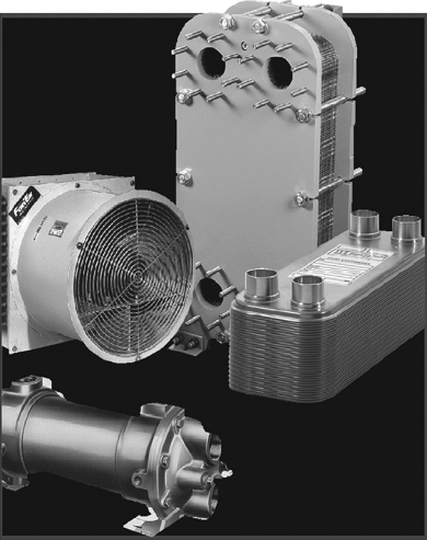
2 Heat Exchanger Design Handbook
1.3.1 ClassifiCation aCCording to ConstruCtion
According to constructional details, heat exchangers are classied as [1] follows:
Tubular heat exchangers—double pipe, shell and tube, coiled tube
Plate heat exchangers (PHEs)—gasketed, brazed, welded, spiral, panel coil, lamella
Extended surface heat exchangers—tube-n, plate-n
Regenerators—xed matrix, rotary matrix
1.3.1.1 Tubular Heat Exchanger
1.3.1.1.1 Double-Pipe Exchangers
A double-pipe heat exchanger has two concentric pipes, usually in the form of a U-bend design. Double-
pipe heat changers with U-bend design are known as hairpin heat exchangers. The ow arrangement is
pure countercurrent. A number of double-pipe heat exchangers can be connected in series or parallel
as necessary. Their usual application is for small duties requiring, typically, less than 300 ft
2
and they
are suitable for high pressures and temperatures and thermally long duties [5]. This has the advantage
of exibility since units can be added or removed as required, and the design is easy to service and
requires low inventory of spares because of its standardization. Either longitudinal ns or circumfer-
ential ns within the annulus on the inner pipe wall are required to enhance the heat transfer from the
inner pipe uid to the annulus uid. Design pressures and temperatures are broadly similar to shell
and tube heat exchangers (STHEs). The design is straightforward and is carried out using the method
of Kern [6] or proprietary programs. The Koch Heat Transfer Company LP, USA, is the pioneer in the
design of hairpin heat exchangers. Figures 1.2 through 1.4 show double-pipe heat exchangers.
1.3.1.1.1.1 Application When the process calls for a temperature cross (when the hot uid
outlet temperature is below the cold uid outlet temperature), a hairpin heat exchanger is the
most efcient design and will result in fewer sections and less surface area. Also, they are com-
monly used for high-fouling services such as slurries and for smaller heat duties. Multitube heat
FIGURE 1.1 Collection of few types of heat exchangers. (Courtesy of ITT STANDARD, Cheektowaga, NY.)

3Heat Exchangers
TABLE 1.1
Heat Exchanger Types: Construction and Performance Features
Type of Heat
Exchanger Constructional Features Performance Features
Double
pipe(hair
pin) heat
exchanger
A double pipe heat exchanger has two concentric
pipes, usually in the form of a U-bend design.
U-bend design is known as hairpin heat
exchangers. The ow arrangement is pure
countercurrent. The surface area ranges from
300 to 6000 ft
2
(nned tubes). Pressure
capabilities are full vacuum to over 14,000 psi
(limited by size, material, and design condition)
and temperature from −100°C to 600°C (−150°F
to 1100°F).
Applicable services: The process results in a
temperature cross, high-pressure stream on
tubeside, a low allowable pressure drop is
required on one side, when the exchanger is
subject to thermal shocks, when ow-induced
vibration may be a problem.
Shell and
tube heat
exchanger
(STHE)
The most commonly used heat exchanger. It is the
“workhorse” of industrial process heat transfer.
They are used as oil cooler, surface condenser,
feed water heater, etc.
The major components of a shell and tube
exchanger are tubes, bafes, shell, front head, rear
head, and nozzles.
Shell diameter: 60 up to 2000 mm. Operating
temperature: −20°C up to 500°C. Operating
pressure max. 600 bar.
Advantages: Extremely exible and robust design,
easy to maintain and repair.
Disadvantages
1. Require large site (footprint) area for
installation and often need extra space to
remove the bundle.
2. Construction is heavy.
3. PHE may be cheaper for pressure below 16 bar
(230 psi) and temperature below 200°C
(392°F).
Coiled tube
heat
exchanger
(CTHE)
Construction of these heat exchangers involves
winding a large number of small-bore ductile
tubes in helix fashion around a central core tube,
with each exchanger containing many layers of
tubes along both the principal and radial axes.
Different uids may be passed in counterow to
the single shellside uid.
Advantages, especially when dealing with
low-temperature applications where
simultaneous heat transfer between more
thantwo streams is desired. Because of small
bore tubes on both sides, CTHEs do not
permitmechanical cleaning and therefore are
used to handle clean, solid-free uids or uids
whose fouling deposits can be cleaned by
chemicals. Materials are usually aluminum
alloys for cryogenics, and stainless
steels for high-temperature applications.
Finned-tube
heat
exchanger
Construction
1. Normal ns on individual tubes referred to as
individually nned tubes.
2. Longitudinal ns on individual tubes, which
aregenerally used in condensing applications
and for viscous uids in double-pipe heat
exchangers.
3. Flat or continuous (plain, wavy, or interrupted)
external ns on an array of tubes (either circular
or at tube).
4. The tube layout pattern is mostly staggered.
Merits: small inventory, low weight, easier
transport, less foundation, better temperature
control
Applications
Condensers and evaporators of air conditioners,
radiators for internal combustion engines, charge
air coolers and intercoolers for cooling
supercharged engine intake air of diesel
engines,etc.
(continued)

4 Heat Exchanger Design Handbook
TABLE 1.1 (continued)
Heat Exchanger Types: Construction and Performance Features
Type of Heat
Exchanger Constructional Features Performance Features
Air cooled
heat
exchanger
(ACHE)
Construction
1. Individually nned tube bundle. The tube
bundleconsists of a series of nned tubes set
between side frames, passing between header
boxes at either end.
2. An air-pumping device (such as an axial ow
fanor blower) across the tube bundle which may
be either forced draft or induced draft.
3. A support structure high enough to allow air to
enter beneath the ACHE.
Merits: Design of ACHE is simpler compared to
STHE, since the airside pressure and temperature
pertain to ambient conditions. Tubeside design is
same as STHE. Maintenance cost is normally
less than that for water-cooled systems. The
fouling on the air side can be cleaned easily.
Disadvantages of ACHEs
ACHEs require large heat transfer surfaces
because of the low heat transfer coefcient on
the air side and the low specic heat of air. Noise
is a factor with ACHEs.
Plate-n heat
exchanger
(PFHE)
Plate n heat exchangers (PFHEs) are a form of
compact heat exchanger consisting of a stack of
alternate at plates called “parting sheets” and n
corrugations, brazed together as a block. Different
ns (such as the plain triangular, louver,
perforated, or wavy n) can be used between
plates for different applications.
Plate-n surfaces are commonly used in gas-to-gas
exchanger applications. They offer high area
densities (up to about 6000 m
2
/m
3
or 1800 ft
2
/ft
3
).
Designed for low-pressure applications, with
operating pressures limited to about 1000 kPa g
(150 psig) and operating temperature from
cryogenic to 150°C (all-aluminum PFHE) and
about 700°C–800°C (1300°F–1500°F) (made of
heat-resistant alloys).
1. PFHE offers superior in thermal performance
compared to extended surface heat exchangers.
2. PFHE can achieve temperature approaches as
low as 1°C between single-phase streams and
3°C between multiphase streams.
3. With their high surface compactness, ability to
handle multiple streams, and with aluminum’s
highly desirable low-temperature properties,
brazed aluminum plate ns are an obvious
choice for cryogenic applications.
4. Very high thermal effectiveness can be achieved;
for cryogenic applications, effectiveness of the
order of 95% and above is common.
Limitations:
1. Narrow passages in plate-n exchangers make
them susceptible for fouling and they cannot be
cleaned by mechanical means. This limits their
use to clean applications like handling air, light
hydrocarbons, and refrigerants.
Regenerator The heat exchanger used to preheat combustion air
iscalled either a recuperator or a regenerator.
Arecuperator is a convective heat transfer type heat
exchanger like tubular, plate-n and extended
surface heat exchangers. The regenerator is classied
as (1) xed matrix or xed bed and (2) rotary
regenerators. The matrix is alternatively heated by
hot uid and cooled by the cold uid. Features:
1. A more compact size (β = 8800 m
2
/m
3
for
rotatingtype and 1600 m
2
/m
3
for xed
matrixtype).
2. Application to both high temperatures
(800°C–1100°C) for metal matrix, and 2000°C
for ceramic regenerators for services like gas
turbine applications, melting furnaces or steam
power plant heat recovery, and low-temperature
applications like space heating (HVAC).
Usage
1. Reheating process feedstock.
2. Waste heat boiler and feed water heating for
generating steam (low-temperature recovery
system).
3. Air preheater—preheating the combustion air
(high temperature heat recovery system).
4. Space heating—rotary heat exchanger (wheel)
is mainly used in building ventilation or in the
air supply/discharge system of air conditioning
equipment.

5Heat Exchangers
TABLE 1.1 (continued)
Heat Exchanger Types: Construction and Performance Features
Type of Heat
Exchanger Constructional Features Performance Features
3. Operating pressure of 5–7 bar for gas turbine
applications and low pressure of 1–1.5 bar for
air dehumidier and waste heat recovery
applications.
4. The absence of a separate ow path like tubes
orplate walls but the presence of seals to
separate the gas stream in order to avoid mixing
due to pressure differential.
Plate heat
exchanger
(PHE)
A plate heat exchanger is usually comprised of a
stack of corrugated or embossed metal plates in
mutual contact, each plate having four apertures
serving as inlet and outlet ports, and seals
designed so as to direct the uids in alternate ow
passages.
Standard performance limits
Maximum operating pressure 25 bar (360 psi)
Maximum temperature 160°C (320°F)
With special gaskets 200°C (390°F)
Maximum ow rate 3600 m
3
/h (950,000
USG/min)
Temperature approach As low as 1°C
Heat recovery As high as 93%
Heat transfer coefcient 3000–7000 W/m
2
·°C
(water–water duties with
normal fouling resistance)
Merits: True counterow, high turbulence and
high heat transfer performance. Close approach
temperature.
Reduced fouling: Cross-contamination eliminated.
Multiple duties with a single unit. Expandable.
Easy to inspect and clean, and less maintenance.
Low liquid volume and quick process control.
Lower cost.
Disadvantages
1. The maximum operating temperature and
pressure are limited by gasket materials. The
gaskets cannot handle corrosive or
aggressivemedia.
2. Gasketed plate heat exchangers cannot handle
particulates that are larger than 0.5 mm.
3. Gaskets always increase the leakage risk.
Exchanger
Other varieties include, brazed plate heat exchanger
(BPHE), shell and plate heat exchanger, welded
plate heat exchanger, wide-gap plate heat
exchanger, free-ow plate heat exchanger,
semi-welded or twin-plate heat exchanger,
double-wall plate heat exchanger, biabon F
graphite plate heat exchanger, etc.
Spiral plate
heat
exchanger
(SPHE)
SPHE is fabricated by rolling a pair of relatively
long strips of plate to form a pair of spiral
passages. Channel spacing is maintained
uniformly along the length of the spiral passages
by means of spacer studs welded to the plate strips
prior to rolling.
Advantages: To handle slurries and liquids with
suspended bers, and mineral ore treatment
where the solid content is up to 50%. The SPHE
is the rst choice for extremely high viscosities,
say up to 500,000 cp, especially in cooling
duties.
Applications: SPHEs are nding applications in
reboiling, condensing, heating or cooling of
viscous uids, slurries, and sludge.
Printed
circuit heat
exchangers
(PCHEs)
HEATRIC printed circuit heat exchangers consist
of diffusion-bonded heat exchanger core that are
constructed from at metal plates into which
uid ow channels are either chemically etched
or pressed. They can withstand pressure of
600bar (9000 psi) with extreme temperatures,
ranging from cryogenic to 700°C (1650°F).
Merits: uid ow can be parallelow,
counterow, crossow, or a combination of these
to suit the process requirements. Thermal
effectiveness is of the order of 98% in a single
unit. They can incorporate more than two
process streams into a single unit.
(continued)

6 Heat Exchanger Design Handbook
TABLE 1.1 (continued)
Heat Exchanger Types: Construction and Performance Features
Type of Heat
Exchanger Constructional Features Performance Features
Lamella heat
exchanger
(LHE)
A lamella heat exchanger normally consists of a
cylindrical shell surrounding a number of heat
transferring lamellas. The design can be
compared to a tube heat exchanger but with the
circular tubes replaced by thin and wide
channels, lamellas. The lamella heat exchanger
works with the media in full counter current
ow. The absence of bafe plates minimizes the
pressure drop and makes handling of most
media possible.
Merits: Since the lamella bundle can be easily
dismantled from the shell, inspection and
cleaning is easy.
Applications
Cooking uid heating in pulp mills.
Liquor preheaters.
Coolers and condensers of ue gas.
Oil coolers.
Heat pipe
heat
exchanger
The heat-pipe heat exchanger used for gas–gas
heat recovery is essentially bundle of nned
tubes assembled like a conventional air-cooled
heat exchanger. The heat pipe consists of three
elements: (1) a working uid inside the tubes,
(2) a wick lining inside the wall, and
(3)vacuum sealed nned tube. The heat-pipe
heat exchanger consists of an evaporative
section through which the hot exhaust gas ows
and a condensation section through which the
cold air ows. These two sections are separated
by a separating wall.
Application: The heat pipes are used for (i) heat
recovery from process uid to preheating of air
for space heating, (ii) HVAC application-waste
heat recovery from the exhaust air to heat the
incoming process air
It virtually does not need mechanical
maintenance, as there are no moving parts. The
heat pipe heat recovery systems are capable of
operating at a temperature of 300°C–315°C with
60%–80% heat recovery capability.
Plate coil
heat
exchanger
(PCHE)
Fabricated from two metal sheets, one or both of
which are embossed. When welded together, the
embossings form a series of well-dened passages
through which the heat transfer media ows.
A variety of standard PLATECOIL
®
fabrications,
such as pipe coil, half pipe, jacketed tanks and
vessels, clamp-on upgrades, immersion heaters
and coolers, heat recovery banks, storage tank
heaters, etc., are available. Easy access to panels
and robust cleaning surfaces reduce maintenance
burdens.
Scraped
surface heat
exchanger
Scraped surface heat exchangers are essentially
double pipe construction with the process uid
in the inner pipe and the cooling (water) or
heating medium (steam) in the annulus. A
rotating element is contained within the tube
and is equipped with spring-loaded blades. In
operation the rotating shaft scraper blades
continuously scrape product lm from the heat
transfer tube wall, thereby enhancing heat
transfer and agitating the product to produce a
homogenous mixture.
Scraped surface heat exchangers are used for
processes likely to result in the substantial
deposition of suspended solids on the heat
transfer surface. Scraped surface heat
exchangers can be employed in the
continuous, closed processing of virtually
any pumpable fluid or slurry involving
cooking, slush freezing, cooling,
crystallizing, mixing, plasticizing, gelling,
polymerizing, heating, aseptic processing,
etc. Use of a scraped surface exchanger
prevents the accumulation of significant
buildup of soliddeposits.
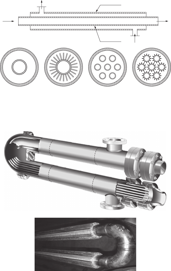
7Heat Exchangers
Outer tube
Inner tube
(i) (ii) (iii) (iv)
(a)
(b)
FIGURE 1.2 Double pipe/twin pipe hairpin heat exchanger. (a) Schematic of the unit, (b): (i) double pipe
with bare internal tube, (ii) double pipe with nned internal tube, (iii) double pipe with multibare inter-
nal tubes, and (iv) double pipe with multinned internal tubes. (Courtesy of Peerless Mfg. Co., Dallas, TX,
Makers of Alco and Bos-Hatten brands of heat exchangers.)
(a)
(b)
FIGURE 1.3 Double pipe/hairpin heat exchanger. (a) 3-D view and (b) tube bundle with longitudinal ns.
(Courtesy of Peerless Mfg. Co., Dallas, TX, Makers of Alco and Bos-Hatten brands of heat exchangers.)
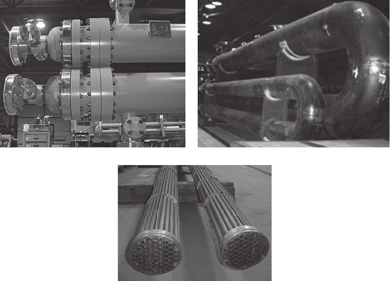
8 Heat Exchanger Design Handbook
exchangers are used for larger heat duties. A hairpin heat exchanger should be considered when
one or more of the following conditions exist:
• The process results in a temperature cross
• High pressure on tubeside application
• A low allowable pressure drop is required on one side
• When an augmentation device to enhance the heat transfer coefcient is desired
• When the exchanger is subject to thermal shocks
• When ow-induced vibration may be a problem
• When solid particulates or slurries are present in the process stream
1.3.1.1.2 Shell and Tube Heat Exchanger
In process industries, shell and tube heat exchangers are used in great numbers, far more than any
other type of exchanger. More than 90% of heat exchangers used in industry are of the shell and
tube type [7]. STHEs are the “workhorses” of industrial process heat transfer [8]. They are the rst
choice because of well-established procedures for design and manufacture from a wide variety of
materials, many years of satisfactory service, and availability of codes and standards for design and
fabrication. They are produced in the widest variety of sizes and styles. There is virtually no limit
on the operating temperature and pressure. Figure 1.5 shows STHEs.
1.3.1.1.3 Coiled Tube Heat Exchanger
Construction of these heat exchangers involves winding a large number of small-bore ductile tubes
in helix fashion around a central core tube, with each exchanger containing many layers of tubes
(a) (b)
(c)
FIGURE 1.4 Hairpin heat exchanger. (a) Separated head closure using separate bolting on shellside and tube-
side and (b) Hairpin exchangers for high-pressure and high-temperature applications and (c) multitubes (bare)
bundle. (Photo courtesy of Heat Exchanger Design, Inc., Indianapolis, IN.)
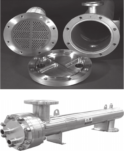
9Heat Exchangers
along both the principal and radial axes. The tubes in individual layers or groups of layers may
be brought together into one or more tube plates through which different uids may be passed in
counterow to the single shellside uid. The construction details have been explained in Refs. [5,9].
The high-pressure stream ows through the small-diameter tubes, while the low-pressure return
stream ows across outside of the small-diameter tubes in the annular space between the inner
central core tube and the outer shell. Pressure drops in the coiled tubes are equalized for each
high-pressure stream by using tubes of equal length and varying the spacing of these in the different
layers. Because of small-bore tubes on both sides, CTHEs do not permit mechanical cleaning and
therefore are used to handle clean, solid-free uids or uids whose fouling deposits can be cleaned
by chemicals. The materials used are usually aluminum alloys for cryogenics and stainless steel for
high-temperature applications.
CTHE offers unique advantages, especially when dealing with low-temperature applications for
the following cases [9]:
• Simultaneous heat transfer between more than two streams is desired. One of the three
classical heat exchangers used today for large-scale liquefaction systems is CTHE.
• A large number of heat transfer units are required.
• High-operating pressures are involved.
CTHE is not cheap because of the material costs, high labor input in winding the tubes, and the
central mandrel, which is not useful for heat transfer but increases the shell diameter [5].
1.3.1.1.3.1 Linde Coil-Wound Heat Exchangers Linde coil-wound heat exchangers are com-
pact and reliable with a broad temperature and pressure range and suitable for both single- and two-
phase streams. Multiple streams can be accommodated in one exchanger. They are known for their
(a)
(b)
FIGURE 1.5 Shell and tube heat exchanger. (a) Components and (b) heat exchanger. (Courtesy of Allegheny
Bradford Corporation, Bradford, PA.)
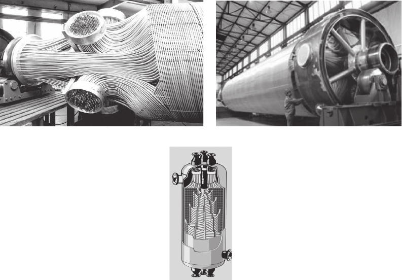
10 Heat Exchanger Design Handbook
robustness in particularly during start-up and shut-down or plant-trip conditions. Both the brazed
aluminum PFHEs and CTHEs nd application in liquecation processes. A comparison of salient
features of these two types of heat exchangers is shown in Chapter 4. Figure1.6 shows Linde coil-
wound heat exchangers.
Glass coil heat exchangers: Two basic types of glass coil heat exchangers are (i) coil type and
(ii) STHE with glass or MS shells in combination with glass tube as standard material for tube.
Glass coil exchangers have a coil fused to the shell to make a one-piece unit. This prohibits leak-
age between the coil and shellside uids [10]. The reduced heat transfer coefcient of boro silicate
glass equipment compares favorably with many alternate tube materials. This is due to the smooth
surface of the glass that improves the lm coefcient and reduces the tendency for fouling. More
details on glass heat exchangers are furnished in Chapter 13.
1.3.1.2 Plate Heat Exchangers
PHEs are less widely used than tubular heat exchangers but offer certain important advantages.
PHEs can be classied into three principal groups:
1. Plate and frame or gasketed PHEs used as an alternative to tube and shell exchangers for
low- and medium-pressure liquid–liquid heat transfer applications
2. Spiral heat exchanger used as an alternative to shell and tube exchangers where low main-
tenance is required, particularly with uids tending to sludge or containing slurries or
solids in suspension
3. Panel heat exchangers made from embossed plates to form a conduit or coil for liquids
coupled with ns
(a)
(b)
(c)
FIGURE 1.6 Coiled tube heat exchanger. (a) End section of a tube bundle, (b) tube bundle under fabrication,
and (c) construction details. (From Linde AG, Engineering Division. With permission.)
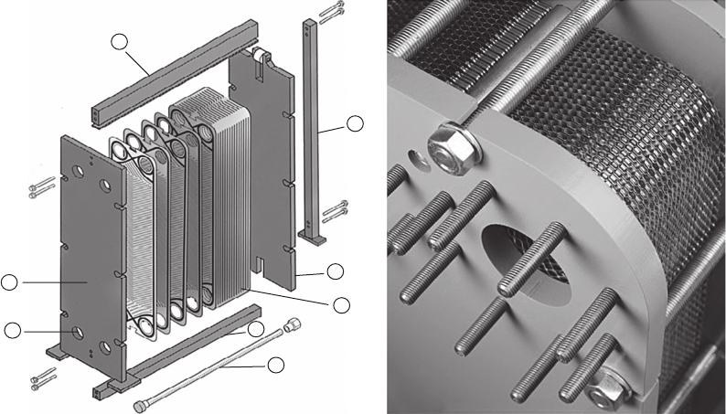
11Heat Exchangers
1.3.1.2.1 Plate and Frame or Gasketed Plate Heat Exchangers
A PHE essentially consists of a number of corrugated metal plates in mutual contact, each plate hav-
ing four apertures serving as inlet and outlet ports, and seals designed to direct the uids in alternate
ow passages. The plates are clamped together in a frame that includes connections for the uids.
Since each plate is generally provided with peripheral gaskets to provide sealing arrangements, PHEs
are called gasketed PHEs. PHEs are shown in Figure 1.7 and are covered in detail in Chapter 7.
1.3.1.2.2 Spiral Plate Heat Exchanger
SPHEs have been used since the 1930s, when they were originally developed in Sweden for heat
recovery in pulp mills. They are classied as a type of welded PHE. An SPHE is fabricated by roll-
ing a pair of relatively long strips of plate around a split mandrel to form a pair of spiral passages.
Channel spacing is maintained uniformly along the length of the spiral passages by means of spacer
studs welded to the plate strips prior to rolling. Figure 1.8 shows an SPHE. For most applications,
both ow channels are closed by alternate channels welded at both sides of the spiral plate. In some
services, one of the channels is left open, whereas the other closed at both sides of the plate. These
two types of construction prevent the uids from mixing.
The SPHE is intended especially for the following applications [5]:
To handle slurries and liquids with suspended bers and mineral ore treatment where the solid
content is up to 50%.
SPHE is the rst choice for extremely high viscosities, say up to 500,000 cp, especially in
cooling duties, because of maldistribution, and hence partial blockage by local overcooling
is less likely to occur in a single-channel exchanger.
SPHEs are nding applications in reboiling, condensing, heating, or cooling of viscous uids,
slurries, and sludge [11].
More details on SPHE are furnished in Chapter 7.
(a) (b)
2
1
7
8
3
5
6
4
FIGURE 1.7 Plate heat exchanger. (a) Construction details—schematic (Parts details: 1, Fixed frame plate; 2, Top
carrying bar; 3, Plate pack; 4, Bottom carrying bar; 5, Movable pressure plate; 6, Support column; 7, Fluids port; and
8, Tightening bolts.) and (b) closer view of assembled plates. (Courtesy of ITT STANDARD, Cheektowaga, NY.)
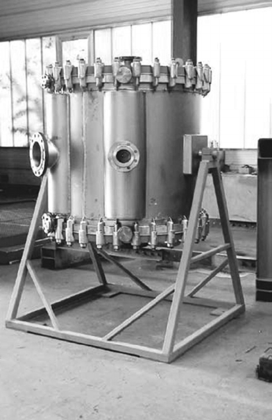
12 Heat Exchanger Design Handbook
1.3.1.2.3 Plate or Panel Coil Heat Exchanger
These exchangers are called panel coils, plate coils, or embossed panel or jacketing. The panel coil
serves as a heat sink or a heat source, depending upon whether the uid within the coil is being
cooled or heated. Panel coil heat exchangers are relatively inexpensive and can be made into any
desired shape and thickness for heat sinks and heat sources under varied operating conditions.
Hence, they have been used in many industrial applications such as cryogenics, chemicals, bers,
food, paints, pharmaceuticals, and solar absorbers.
Construction details of a panel coil: A few types of panel coil designs are shown in Figure1.9.
The panel coil is used in such industries as plating, metal nishing, chemical, textile, brewery,
pharmaceutical, dairy, pulp and paper, food, nuclear, beverage, waste treatment, and many others.
Construction details of panel coils are discussed next. M/s Paul Muller Company, Springeld, MO,
and Tranter, Inc., TX, are the leading manufacturers of panel coil/plate coil heat exchangers.
Single embossed surface: The single embossed heat transfer surface is an economical type to utilize
for interior tank walls, conveyor beds, and when a at side is required. The single embossed design
uses two sheets of material of different thickness and is available in stainless steel, other alloys,
carbon steel, and in many material gages and working pressures.
Double embossed surface: Inated on both sides using two sheets of material and the same thick-
ness, the double embossed construction maximizes the heating and cooling process by utilizing
both sides of the heat transfer plate. The double embossed design is commonly used in immersion
applications and is available in stainless steel, other alloys, carbon steel, and in many material gages
and working pressures.
FIGURE 1.8 Spiral plate heat exchanger. (Courtesy of Tranter, Inc., Wichita Falls, TX.)
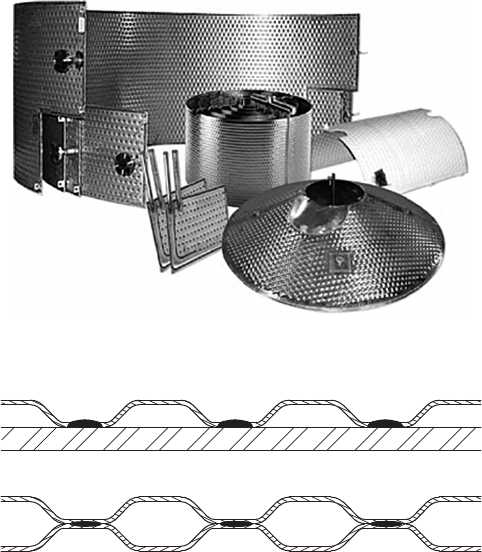
13Heat Exchangers
Dimpled surface: This surface is machine punched and swaged, prior to welding, to increase
the flow area in the passages. It is available in stainless steel, other alloys, carbon steel, in
many material gages and working pressures, and in both MIG plug-welded and resistance spot-
welded forms.
Methods of manufacture of panel coils: Basically, three different methods have been used to
manufacture the panel coils: (1) they are usually welded by the resistance spot-welding or seam-
welding process. An alternate method now available offers the ability to resistance spot-weld the
dimpled jacket-style panel coil with a perimeter weldment made with the GMAW or resistance
welding. Figure 1.10 shows a vessel jacket welded by GMAW and resistance-welding process. Other
methods are (2) the die-stamping process and (3) the roll-bond process. In the die-stamping process,
ow channels are die-stamped on either one or two metal sheets. When one sheet is embossed and
joined to a at (unembossed sheet), it forms a single-sided embossed panel coil. When both sheets
are stamped, it forms a double-sided embossed panelcoil.
Types of jackets: Jacketing of process vessels is usually accomplished by using one of the three
main available types: conventional jackets, dimple jackets, and half-pipe coil jackets [12].
Advantages of panel coils: Panel coils provide the optimum method of heating and cooling pro-
cess vessels in terms of control, efciency, and product quality. Using a panel as a means of heat
transfer offers the following advantages [12]:
• All liquids can be handled, as well as steam and other high-temperature vapors.
• Circulation, temperature, and velocity of heat transfer media can be accurately controlled.
• Panels may often be fabricated from a much less expensive metal than the vessel itself.
• Contamination, cleaning, and maintenance problems are eliminated.
FIGURE 1.9 Temp-Plate
®
heat transfer surface. (Courtesy of Mueller, Heat Transfer Products, Springeld, MO.)
(a)
(b)
FIGURE 1.10 Welded dimpled jacket template. (a) Gas metal arc welded and (b) resistance welded.
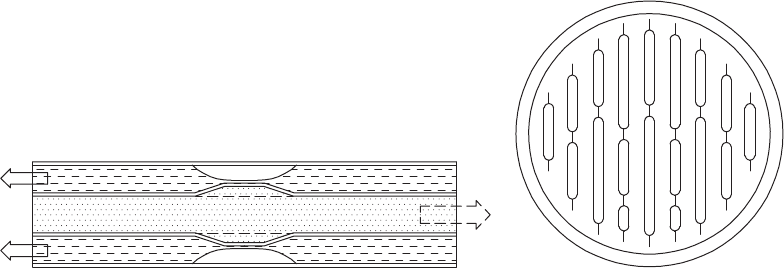
14 Heat Exchanger Design Handbook
• Maximum efciency, economy, and exibility are achieved.
• In designing reactors for specic process, this variety gives chemical engineers a great
deal of exibility in the choice of heat transfer medium.
1.3.1.2.4 Lamella Heat Exchanger
The lamella heat exchanger is an efcient, and compact, heat exchanger. The principle was
originally developed around 1930 by Ramens Patenter. Later Ramens Patenter was acquired by
Rosenblads Patenter and the lamella heat exchanger was marketed under the Rosenblad name. In
1988, Berglunds acquired the product and continued to develop it. A lamella heat exchanger nor-
mally consists of a cylindrical shell surrounding a number of heat-transferring lamellas. The design
can be compared to a tube heat exchanger but with the circular tubes replaced by thin and wide
channels, lamellas. Sondex Tapiro Oy Ab Pikkupurontie 11, FIN-00810 Helsinki, Finland, markets
lamella heat exchangers worldwide.
The lamella is a form of welded heat exchanger that combines the construction of a PHE with
that of a shell and tube exchanger without bafes. In this design, tubes are replaced by pairs of thin
at parallel metal plates, which are edge welded to provide long narrow channels, and banks of
these elements of varying width are packed together to form a circular bundle and tted within a
shell. The cross section of a lamella heat exchanger is shown schematically in Figure 1.11. With this
design, the ow area on the shellside is a minimum and similar in magnitude to that of the inside
of the bank of elements; due to this, the velocities of the two liquid media are comparable [13]. The
ow is essentially longitudinal countercurrent “tubeside” ow of both tube and shell uids [4]. Due
to this, the velocities of the two liquid media are comparable. Also, the absence of bafes minimizes
the pressure drop. One end of the element pack is xed and the other is oating to allow for thermal
expansion and contraction. The connections tted at either end of the shell, as in the normal shell
and tube design, allow the bank of elements to be withdrawn, making the outside surface accessible
for inspection and cleaning. Opposed from an STHE, where the whole exchanger has to be replaced
in case of damage, it is possible just to replace the lamella battery and preserve the existing shell.
Lamella heat exchangers can be fabricated from carbon steel, stainless steel, titanium, Incolly, and
Hastelloy. They can handle most uids, with large volume ratios between uids. The oating nature
of the bundle usually limits the working pressure to 300 psi. Lamella heat exchangers are generally
used only in special cases. Design is usually done by the vendors.
Merits of lamella heat exchanger are as follows:
1. Strong turbulence in the uid
2. High operation pressure
(a) (b)
FIGURE 1.11 Lamella heat exchanger. (a) Counterow concept and (b) lamella tube bundle.
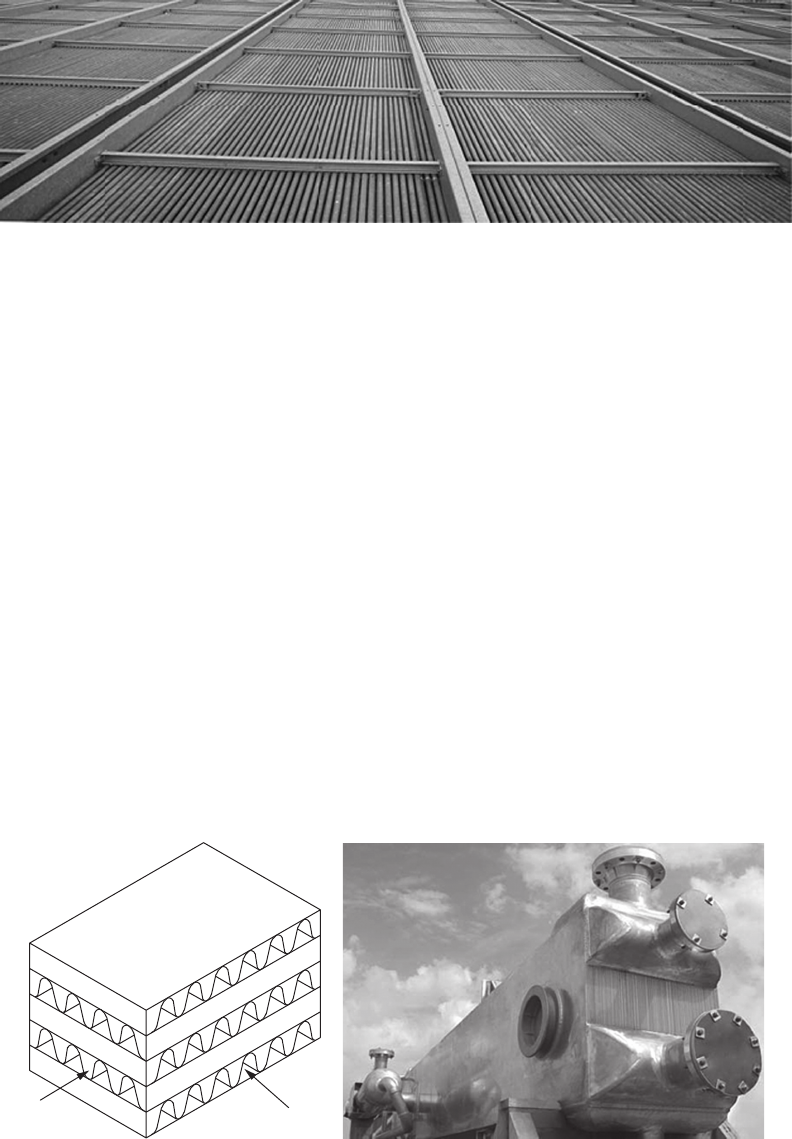
15Heat Exchangers
Applications
Cooking uid heating in pulp mills
Liquor preheaters
Coolers and condensers of ue gas
Oils coolers
1.3.1.3 Extended Surface Exchangers
In a heat exchanger with gases or some liquids, if the heat transfer coefcient is quite low, a large
heat transfer surface area is required to increase the heat transfer rate. This requirement is served
by ns attached to the primary surface. Tube-n heat exchangers (Figure 1.12) and plate-n heat
exchangers (Figure 1.13) are the most common examples of extended surface heat exchangers. Their
design is covered in Chapter 4.
1.3.1.4 Regenerative Heat Exchangers
Regeneration is an old technology dating back to the rst open hearths and blast furnace stoves.
Manufacturing and process industries such as glass, cement, and primary and secondary metals
account for a signicant fraction of all energy consumed. Much of this energy is discarded in the
form of high-temperature exhaust gas. Recovery of waste heat from the exhaust gas by means of
heat exchangers known as regenerators can improve the overall plant efciency [14].
Types of regenerators: Regenerators are generally classied as xed-matrix and rotary regenera-
tors. Further classications of xed and rotary regenerators are shown in Figure 1.14. In the former,
FIGURE 1.12 Air-cooled condenser. (Courtesy of GEA Iberica S.A., Vizcaya, Spain.)
(a) (b)
FIGURE 1.13 Plate-n heat exchanger. (a) Schematic of exchanger and (b) brazed aluminum plate-n heat
exchanger. (From Linde AG, Engineering Division. With permission.)
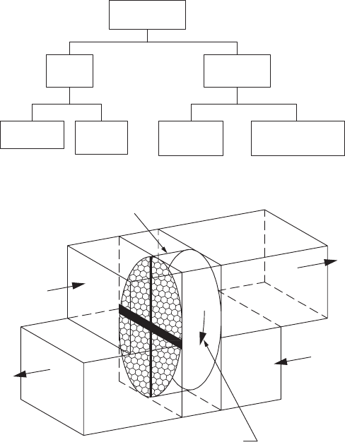
16 Heat Exchanger Design Handbook
regeneration is achieved with periodic and alternate blowing of hot and the cold stream through a
xed matrix. During the hot ow period, the matrix receives thermal energy from the hot gas and
transfers it to the cold stream during the cold stream ow. In the latter, the matrix revolves slowly
with respect to two uid streams. The rotary regenerator is commonly employed in gas turbine
power plants where the waste heat in the hot exhaust gases is utilized for raising the temperature
of compressed air before it is supplied to the combustion chamber. A rotary regenerator (rotary
wheel for HVAC application) working principle is shown in Figure 1.15, and Figure 1.16 shows the
Rothemuhle regenerative air preheater of Babcock and Wilcox Company. Rotary regenerators fall
in the category of compact heat exchangers since the heat transfer surface area to regenerator vol-
ume ratio is very high. Regenerators are further discussed in detail in Chapter 6.
1.3.2 ClassifiCation aCCording to transfer ProCess
These classications are as follows:
Indirect contact type—direct transfer type, storage type, uidized bed
Direct contact type—cooling towers
1.3.2.1 Indirect Contact Heat Exchangers
In an indirect contact–type heat exchanger, the uid streams remain separate and the heat transfer
takes place continuously through a dividing impervious wall. This type of heat exchanger can be
further classied into direct transfer type, storage type, and uidized bed exchangers. Direct transfer
type is dealt with next, whereas the storage type and the uidized bed type are discussed in Chapter 6.
Regenerator
Rotary
regenerator
Rotary
matrix
Fixed matrix—
rotating hoods
Fixed
matrix
Dual bed
valved
Single bed
FIGURE 1.14 Classication of regenerators.
Rotating regenerator
Atmospheric
cold air
Cooled
exhaust air
Direction of
rotation
Warm room
exhaust air
Warm ai
r
to room
FIGURE 1.15 Rotary regenerator: working principle.
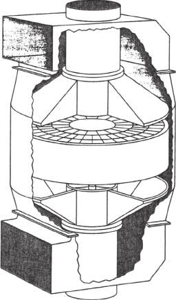
17Heat Exchangers
1.3.2.1.1 Direct Transfer–Type Exchangers
In this type, there is a continuous ow of heat from the hot uid to the cold uid through a separat-
ing wall. There is no direct mixing of the uids because each uid ows in separate uid passages.
There are no moving parts. This type of exchanger is designated as a recuperator. Some examples
of direct transfer–type heat exchangers are tubular exchangers, PHEs, and extended surface exchangers.
Recuperators are further subclassied as prime surface exchangers, which do not employ ns or
extended surfaces on the prime surface. Plain tubular exchangers, shell and tube exchangers with
plain tubes, and PHEs are examples of prime surface exchangers.
1.3.2.2 Direct Contact–Type Heat Exchangers
In direct contact–type heat exchangers, the two uids are not separated by a wall and come into
direct contact, exchange heat, and are then separated.
Owing to the absence of a wall, closer temperature approaches are attained. Very often, in the
direct contact type, the process of heat transfer is also accompanied by mass transfer. Various types
of direct contact heat exchangers include (a) immiscible uid exchanger, (b) gas–liquid exchanger,
and (c) liquid–vapor exchanger. The cooling towers and scrubbers are examples of a direct contact–
type heat exchanger.
1.3.3 ClassifiCation aCCording to surfaCe ComPaCtness
Compact heat exchangers are important when there are restrictions on the size and weight of
exchangers. A compact heat exchanger incorporates a heat transfer surface having a high area den-
sity, β, somewhat arbitrarily 700 m
2
/m
3
(200 ft
2
/ft
3
) and higher [1]. The area density, β, is the ratio
of heat transfer area A to its volume V. A compact heat exchanger employs a compact surface on one
or more sides of a two-uid or a multiuid heat exchanger. They can often achieve higher thermal
effectiveness than shell and tube exchangers (95% vs. the 60%–80% typical for STHEs), which
2
1
2
FIGURE 1.16 Rothemuhle regenerative air preheater of Babcock and Wilcox Company—stationary matrix
(part 1) and revolving hoods (part 2). (Adapted from Mondt, J.R., Regenerative heat exchangers: The elements
of their design, selection and use, Research Publication GMR-3396, General Motors Research Laboratories,
Warren, MI, 1980.)
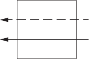
18 Heat Exchanger Design Handbook
makes them particularly useful in energy-intensive industries [15]. For least capital cost, the size
of the unit should be minimal. There are some additional advantages to small volume as follows:
Small inventory, making them good for handling expensive or hazardous materials [15]
Low weight
Easier transport
Less foundation
Better temperature control
Some barriers to the use of compact heat exchangers include [15] the following:
The lack of standards similar to pressure vessel codes and standards, although this is now
being redressed in the areas of plate-n exchangers [16] and air-cooled exchangers [17].
Narrow passages in plate-n exchangers make them susceptible for fouling and they cannot
be cleaned by mechanical means. This limits their use to clean applications like handling
air, light hydrocarbons, and refrigerants.
1.3.4 ClassifiCation aCCording to flow arrangement
The basic ow arrangements of the uids in a heat exchanger are as follows:
Parallelow
Counterow
Crossow
The choice of a particular ow arrangement is dependent upon the required exchanger effective-
ness, uid ow paths, packaging envelope, allowable thermal stresses, temperature levels, and other
design criteria. These basic ow arrangements are discussed next.
1.3.4.1 Parallelflow Exchanger
In this type, both the uid streams enter at the same end, ow parallel to each other in the same direc-
tion, and leave at the other end (Figure 1.17). (For uid temperature variations, idealized as one-dimen-
sional, refer Figure 2.2 of Chapter 2.) This arrangement has the lowest exchanger effectiveness among
the single-pass exchangers for the same ow rates, capacity rate (mass × specic heat) ratio, and surface
area. Moreover, the existence of large temperature differences at the inlet end may induce high thermal
stresses in the exchanger wall at inlet. Parallelows are advantageous. (a) In heating very viscous uids,
parallelow provides for rapid heating. The quick change in viscosity results in reduced pumping power
requirements through the heat exchanger, (b) where the more moderate mean metal temperatures of the
tube walls are required, and (c) where the improvements in heat transfer rates compensate for the lower
LMTD. Although this ow arrangement is not used widely, it is preferred for the following reasons [2]:
1. When there is a possibility that the temperature of the warmer uid may reach its freezing point.
2. It provides early initiation of nucleate boiling for boiling applications.
3. For a balanced exchanger (i.e., heat capacity rate ratio C* = 1), the desired exchanger effec-
tiveness is low and is to be maintained approximately constant over a range of NTU values.
4. The application allows piping only suited to parallelow.
1
2
FIGURE 1.17 Parallelow arrangement.
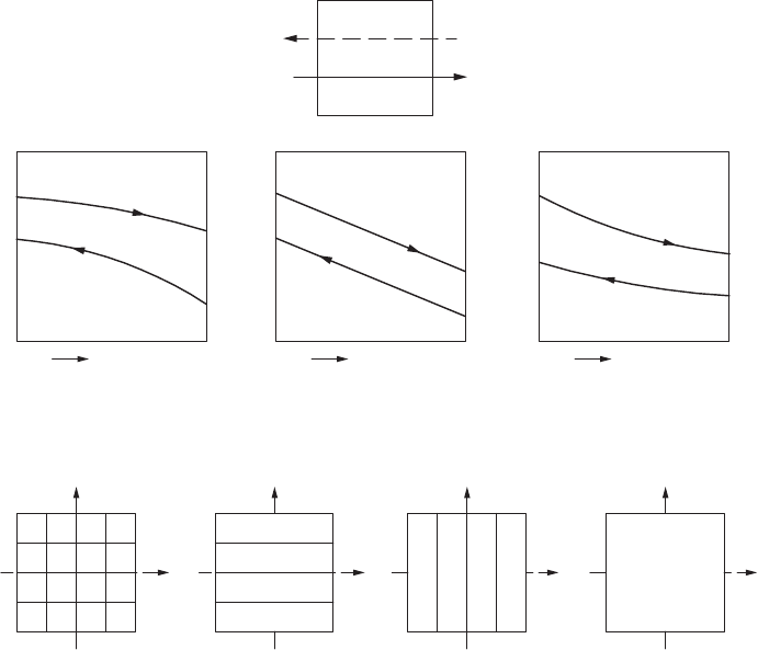
19Heat Exchangers
5. Temperature-sensitive uids such as food products, pharmaceuticals, and biological prod-
ucts are less likely to be “thermally damaged” in a parallelow heat exchanger.
6. Certain types of fouling such as chemical reaction fouling, scaling, corrosion fouling, and
freezing fouling are sensitive to temperature. Where control of temperature-sensitive foul-
ing is a major concern, it is advantageous to use parallelow.
1.3.4.2 Counterflow Exchanger
In this type, as shown in Figure 1.18a, the two uids ow parallel to each other but in opposite
directions, and its temperature distribution may be idealized as shown in Figure 1.18b. Ideally,
this is the most efcient of all ow arrangements for single-pass arrangements under the same
parameters. Since the temperature difference across the exchanger wall at a given cross section
is the lowest, it produces minimum thermal stresses in the wall for equivalent performance com-
pared to other ow arrangements. In certain types of heat exchangers, counterow arrangement
cannot be achieved easily, due to manufacturing difculties associated with the separation of the
uids at each end, and the design of inlet and outlet header design is complex and difcult [2].
1.3.4.3 Crossflow Exchanger
In this type, as shown in Figure 1.19, the two uids ow normal to each other. Important types of
ow arrangement combinations for a single-pass crossow exchanger include the following:
• Both uids unmixed
• One uid unmixed and the other uid mixed
• Both uids mixed
2
1
(a)
t
h,i
C
h
> C
c
Hot fluid
Hot fluid
Hot fluid
Cold fluid
Cold fluid
Cold fluid
Flow length Flow length Flow length
C
h
< C
c
C
h
= C
c
t
c,o
t
h,i
t
h,o
t
c,o
t
c,i
t
h,i
t
h,o
t
c,o
t
c,i
t
h,
o
t
c,i
(b)
FIGURE 1.18 (a) Counterow arrangement (schematic) and (b) temperature distribution (schematic). (Note:
C
h
and C
c
are the heat capacity rate of hot uid and cold uid respectively, i refers to inlet, o refers to outlet
conditions and t refers to uid temperature.)
1
2(a)
1
2(b)
1
2
1
2 (c)
FIGURE 1.19 Crossow arrangement: (a) unmixed–unmixed, (b) unmixed–mixed, and (c) mixed–mixed.
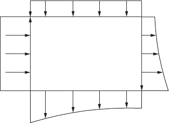
20 Heat Exchanger Design Handbook
A uid stream is considered “unmixed” when it passes through individual ow passage without any
uid mixing between adjacent ow passages. Mixing implies that a thermal averaging process takes
place at each cross section across the full width of the ow passage. A tube-n exchanger with at
(continuous) ns and a plate-n exchanger wherein the two uids ow in separate passages (e.g.,
wavy n, plain continuous rectangular or triangular ow passages) represent the unmixed–unmixed
case. A crossow tubular exchanger with bare tubes on the outside would be treated as the unmixed–
mixed case, that is, unmixed on the tubeside and mixed on the outside. The both uid mixed case
is practically a less important case and represents a limiting case of some multipass shell and tube
exchangers (TEMA E and J shell).
For the unmixed–unmixed case, uid temperature variations are idealized as two-dimensional
only for the inlet and outlet sections; this is shown in Figure 1.20. The thermal effectiveness for
the crossow exchanger falls in between those of the parallelow and counterow arrangements.
This is the most common ow arrangement used for extended surface heat exchangers because it
greatly simplies the header design. If the desired heat exchanger effectiveness is generally more
than 80%, the size penalty for crossow may become excessive. In such a case, a counterow unit
is preferred [2]. In shell and tube exchangers, crossow arrangement is used in the TEMA X shell
having a single tube pass.
1.3.5 ClassifiCation aCCording to Pass arrangements
These are either single pass or multipass. A uid is considered to have made one pass if it ows
through a section of the heat exchanger through its full length once. In a multipass arrangement, a
uid is reversed and ows through the ow length two or more times.
1.3.5.1 Multipass Exchangers
When the design of a heat exchanger results in either extreme length, signicantly low veloci-
ties, or low effectiveness, or due to other design criteria, a multipass heat exchanger or several
single-pass exchangers in series or a combination of both is employed. Specically, multipassing
is resorted to increase the exchanger thermal effectiveness over the individual pass effectiveness.
As the number of passes increases, the overall direction of the two uids approaches that of a pure
counterow exchanger. The multipass arrangements are possible with compact, shell and tube, and
plate exchangers.
t
c,i
t
c,o
Hot fluid outle
t
temperature
distribution
t
h,i
t
h,o
Cold fluid outlet
temperature
distribution
FIGURE 1.20 Temperature distribution for unmixed–unmixed crossow arrangement.
21Heat Exchangers
1.3.6 ClassifiCation aCCording to Phase of fluids
1.3.6.1 Gas–Liquid
Gas–liquid heat exchangers are mostly tube-n-type compact heat exchangers with the liquid on the
tubeside. The radiator is by far the major type of liquid–gas heat exchanger, typically cooling the
engine jacket water by air. Similar units are necessary for all the other water-cooled engines used in
trucks, locomotives, diesel-powered equipment, and stationery diesel power plants. Other examples
are air coolers, oil coolers for aircraft, intercoolers and aftercoolers in compressors, and condensers
and evaporators of room air-conditioners. Normally, the liquid is pumped through the tubes, which
have a very high convective heat transfer coefcient. The air ows in crossow over the tubes. The
heat transfer coefcient on the air side will be lower than that on the liquid side. Fins will be gener-
ally used on the outside of the tubes to enhance the heat transfer rate.
1.3.6.2 Liquid–Liquid
Most of the liquid–liquid heat exchangers are shell and tube type, and PHEs to a lesser extent. Both
uids are pumped through the exchanger, so the principal mode of heat transfer is forced convec-
tion. The relatively high density of liquids results in very high heat transfer rate, so normally ns
or other devices are not used to enhance the heat transfer [4]. In certain applications, low-nned
tubes, micron tubes, and heat transfer augmentation devices are used to enhance the heat transfer.
1.3.6.3 Gas–Gas
This type of exchanger is found in exhaust gas–air preheating recuperators, rotary regenerators,
intercoolers, and/or aftercoolers to cool supercharged engine intake air of some land-based die-
sel power packs and diesel locomotives, and cryogenic gas liquefaction systems. In many cases,
one gas is compressed so that the density is high while the other is at low pressure and low den-
sity. Compared to liquid–liquid exchangers, the size of the gas–gas exchanger will be much larger,
because the convective heat transfer coefcient on the gas side is low compared to the liquid side.
Therefore, secondary surfaces are mostly employed to enhance the heat transfer rate.
1.3.7 ClassifiCation aCCording to heat transfer meChanisms
The basic heat transfer mechanisms employed for heat transfer from one uid to the other are
(1) single-phase convection, forced or free, (2) two-phase convection (condensation or evaporation)
by forced or free convection, and (3) combined convection and radiation. Any of these mechanisms
individually or in combination could be active on each side of the exchanger. Based on the phase
change mechanisms, the heat exchangers are classied as (1) condensers and (2) evaporators.
1.3.7.1 Condensers
Condensers may be liquid (water) or gas (air) cooled. The heat from condensing streams may be used
for heating uid. Normally, the condensing uid is routed (1) outside the tubes with a water-cooled
steam condenser or (2) inside the tubes with gas cooling, that is, air-cooled condensers of refrigera-
tors and air-conditioners. Fins are normally provided to enhance heat transfer on the gas side.
1.3.7.2 Evaporators
This important group of tubular heat exchangers can be subdivided into two classes: red systems
and unred systems.
Fired systems: These involve the products of combustion of fossil fuels at very high temperatures
but at ambient pressure (and hence low density) and generate steam under pressure. Fired systems
are called boilers. A system may be a re tube boiler (for small low-pressure applications) or a water
tube boiler.

22 Heat Exchanger Design Handbook
Unred systems: These embrace a great variety of steam generators extending over a broad
temperature range from high-temperature nuclear steam generators to very-low-temperature cryo-
genic gasiers for liquid natural gas evaporation. Many chemical and food processing applications
involve the use of steam to evaporate solvents, concentrate solutions, distill liquors, or dehydrate
compounds.
1.3.8 other ClassifiCations
1.3.8.1 Micro Heat Exchanger
Micro- or microscale heat exchangers are heat exchangers in which at least one uid ows in lateral
connements with typical dimensions below 1 mm and are fabricated via silicon micromachin-
ing, deep x-ray lithography, or nonlithographic micromachining [18]. The plates are stacked forming
“sandwich” structures, as in the “large” plate exchangers. All ow congurations (cocurrent, coun-
tercurrent, and crossow) are possible.
Typically, the uid ows through a cavity called a microchannel. Microheat exchangers have
been demonstrated with high convective heat transfer coefcient. Investigation of microscale
thermal devices is motivated by the single-phase internal ow correlation for convective heat
transfer:
h
k
D
=
Nu
h
where
h is the heat transfer coefcient
Nu is the Nusselt number
k is the thermal conductivity of the uid
D
h
is the hydraulic diameter of the channel or duct
In internal laminar ows, the Nusselt number becomes a constant. As the Reynolds number is
proportional to hydraulic diameter, uid ow in channels of small hydraulic diameter will predomi-
nantly be laminar. This correlation therefore indicates that the heat transfer coefcient increases as
the channel diameter decreases. Heat transfer enhancement in laminar ow is further discussed in
Chapter 8 Section 8.3.3.
1.3.8.1.1 Advantages over Macroscale Heat Exchangers
• Substantially better performance
• Enhanced heat transfer coefcient with a large number of smaller channels
• Smaller size that allows for an increase in mobility and uses
• Light weight reduces the structural and support requirements
• Lower cost due to less material being used in fabrication
1.3.8.1.2 Applications of Microscale Heat Exchangers
Microscale heat exchangers are being used in the development of fuel cells. They are currently used
in automotive industries, HVAC applications, aircraft, manufacturing industries, and electronics
cooling.
1.3.8.1.3 Demerits of Microscale Heat Exchangers
One of the main disadvantages of microchannel heat exchangers is the high-pressure loss that is
associated with a small hydraulic diameter.
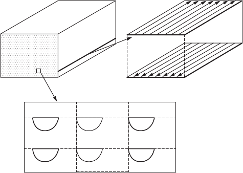
23Heat Exchangers
1.3.8.2 Printed Circuit Heat Exchanger
PCHE, developed by Heatric Division of Meggitt (UK) Ltd., is a promising heat exchanger because
it is able to withstand pressures up to 50 MPa and temperatures from cryogenic to 700°C. It is
extremely compact (the most common design feature to achieve compactness has been small chan-
nel size) and has high efciency, of the order of 98%. It can handle a wide variety of clean uids. The
ow conguration can be either crossow or counterow. It will maintain parent material strength
and can be made from stainless steel, nickel alloys, copper alloys, and titanium. Fluid ow channels
are etched chemically on metal plates. It has a typical plate thickness of 1.6 mm, width 600 mm, and
length 1200 mm. The channels are semicircular with 1–2 mm diameter. Etched plates are stacked
and diffusion bonded together to fabricate as a block. The blocks are then welded together to form
the complete heat exchanger core, as shown in Figure 1.21a.
HEATRIC PCHEs consist of diffusion-bonded heat exchanger core that are constructed
from at metal plates into which uid ow channels are either chemically etched or pressed.
The required conguration of the channels on the plates for each uid is governed by the
operating temperature and pressure-drop constraints for the heat exchange duty and the chan-
nels can be of unlimited variety and complexity. Fluid ow can be parallelow, counterow,
crossow, or a combination of these to suit the process requirements. Figure 1.21b through f
shows HEATRIC PCHE.
The etched plates are then stacked and diffusion-bonded together to form strong, compact, all
metal heat exchanger core. Diffusion bonding is a “solid-state joining” process entailing pressing
metal surfaces together at temperatures below the melting point, thereby promoting grain growth
between the surfaces. Under carefully controlled conditions, diffusion-bonded joints reach parent
metal strength and stacks of plates are converted into solid blocks containing the uid ow pas-
sages. The blocks are then welded together to form the complete heat exchange core. Finally,head-
ers and nozzles are welded to the core in order to direct the uids to the appropriate sets of passages.
Welded and diffusion-bonded PCHEs employ no gaskets or braze material, resulting in superior
integrity compared to other technologies that may use gaskets or brazing as part of their construc-
tion. (Gaskets or braze material can be potential sources of leakage, uid incompatibility, and tem-
perature limitations.) The mechanical design is normally of ASME VIII Division 1. Other design
codes can be employed as required.
(a)
FIGURE 1.21 Printed circuit heat exchanger. (a) Heat exchanger block with ow channel.
(continued)
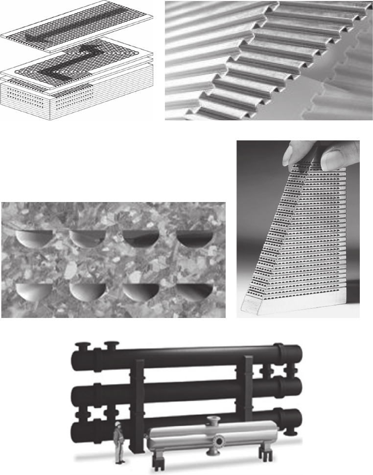
24 Heat Exchanger Design Handbook
1.3.8.2.1 Materials of Construction
The majority of diffusion-bonded heat exchangers are constructed from 300 series austenitic
stainless steel. Various other metals that are compatible with the diffusion-bonded process
and have been qualied for use include 22 chromeduplex, copper–nickel, nickel alloys, and
titanium.
(b
) (c)
(d
)(
e)
(f)
FIGURE 1.21 (continued) Printed circuit heat exchanger. (b) Flow channel, (c) and (d) section through ow
channel, (e)diffusion bonded core, (f) comparison of size of PCHE shell and tube heat exchanger (smaller
size) with a conventional exchanger (bigger size) for similar duty. (Courtesy of Heatric UK, Dorset, U.K.)
25Heat Exchangers
1.3.8.2.2 Features of PCHE
Diffusion-bonded heat exchangers are highly compact and robust that are well established in the
upstream hydrocarbon processing, petrochemical and rening industries. Various salient construc-
tional and performance features are given next:
1. Compactness: Diffusion-bonded heat exchangers are 1/4–1/6th the conventional STHEs of
the equivalent heat duty. This design feature has space and weight advantages, reducing
exchanger size together with piping and valve requirements. The diffusion-bonded heat
exchanger in the foreground of Figure 1.21e undertakes the same thermal duty, at the same
pressure drop, as the stack of three shell and tube exchangers behind. PCHE might be
judged as a promising compact heat exchanger for the high efciency recuperator [19].
2. Process capability: They can withstand pressures of 600 bar (9000 psi) or excess and can
cope with extreme temperatures, ranging from cryogenic to 900°C (1650°F).
3. Thermal effectiveness: Diffusion-bonded exchangers can achieve high thermal effective-
ness of the order of 98% in a single unit.
4. They can incorporate more than two process streams into a single unit.
5. The compatibility of the chemical etching and diffusion-bonding process with a wide range
of materials ensure that they are suitable for a range of corrosive and high puritystreams.
1.3.8.3 Perforated Plate Heat Exchanger as Cryocoolers
High-efciency compact heat exchangers are needed in cryocoolers to achieve very low temperatures.
One approach to meet the requirements for compact and efcient cooling systems is the perforated
PHE. Such heat exchangers are made up of a large number of parallel, perforated plates of high-
thermal conductivity metal in a stacked array, with gaps between plates being provided by spacers.
Gas ows longitudinally through the plates in one direction and other stream ows in the opposite
direction through separated portions of the plates. Heat transfer takes place laterally across the plates
from one stream to the other. The operating principles of this type of heat exchanger are described by
Fleming [20]. The device employs plates of 0.81 mm thickness with holes of 1.14 mm in diameter and a
resulting length-to-diameter ratio in the range of 0.5–1.0. The device is designed to operate from room
temperature to 80 K. In order to improve operation of a compact cryocooler, much smaller holes, in the
low-micron-diameter range, and thinner plates with high length-to-diameter ratio are needed. As per
US Patent 5101894 [21], uniform, tubular perforations having diameters down to the low-micron-size
range can be obtained. Various types of heat exchange devices including recuperative and regenera-
tive heat exchangers may be constructed in accordance with the invention for use in cooling systems
based on a number of refrigeration cycles such as the Linde–Hampson, Brayton, and Stirling cycles.
1.3.8.4 Scraped Surface Heat Exchanger
Scraped surface heat exchangers are used for processes likely to result in the substantial deposi-
tion of suspended solids on the heat transfer surface. Scraped surface heat exchangers can be
employed in the continuous, closed processing of virtually any pumpable uid or slurry involv-
ing cooking, slush freezing, cooling, crystallizing, mixing, plasticizing, gelling, polymerizing,
heating, aseptic processing, etc. Use of a scraped surface exchanger prevents the accumulation of
signicant buildup of solid deposits. The construction details of scraped surface heat exchangers
are explained in Ref. [4]. Scraped surface heat exchangers are essentially double pipe construc-
tion with the process uid in the inner pipe and the cooling (water) or heating medium (steam) in
the annulus. A rotating element is contained within the tube and is equipped with spring-loaded
blades. In operation, the rotating shaft scraper blades continuously scrape product lm from the
heat transfer tube wall, thereby enhancing heat transfer and agitating the product to produce a
homogenous mixture. For most applications, the shaft is mounted in the center of the heat transfer
tube. An off-centered shaft mount or eccentric design is recommended for viscous and sticky
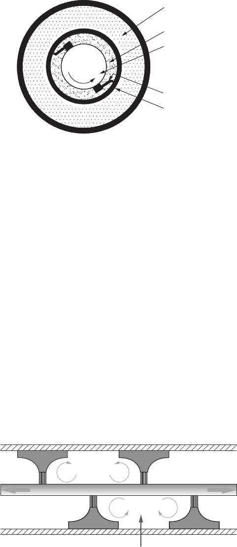
26 Heat Exchanger Design Handbook
products. This shaft arrangement increases product mixing and reduces the mechanical heat load.
Oval tubes are used to process extremely viscous products. All pressure elements are designed in
accordance with the latest ASME code requirements. The principle of working of scraped surface
heat exchangers is shown in Figure1.22. For scraped surface exchangers, operating costs are high
and applications are highly specic [5]. Design is mostly done by vendors. The leading manufac-
tures include HRS Heat Exchangers, Ltd., UK, and Waukesha Cherry-Burrell, USA.
1.3.8.4.1 Unicus Scraped Surface Heat Exchanger
Unicus™ is the trade name for scraped surface heat exchanger of HRS Heat Exchangers Ltd., UK,
for high-fouling and viscous uid applications. The design is based on STHE with scraping ele-
ments inside each interior tube. The scrapers are moved back and forth by hydraulic action. The
scraping action has two very important advantages: any fouling on the tube wall is removed and the
scraping movement introduces turbulence in the uid increasing heat transfer.
1.3.8.4.1.1 Elements of the Unicus Unicus consists of three parts: a hydraulic cylinder that
moves the scraper bars, the STHE part, and a chamber that separates both the elements. The hydrau-
lic cylinder is connected to a hydraulic power pack. The smaller models of the Unicus range can be
supplied with a pneumatic cylinder. The scraping system consists of a stainless steel rod to which
the scraping elements are tted, as shown in Figure 1.23, and Figure 1.24 shows Unicus scraped
surface heat exchangers. The pictures show the various types of scrapers that can be applied. For
each application, the optimal scraper is selected and tted.
Service fluid
Service fluid
Heat transfer
Scraper
Tube wall
Scraper ba
r
Extra
turbulence
Product
FIGURE 1.23 Principle of Unicus scraped surface heat exchanger working. (Courtesy of HRS Heat
Exchangers Ltd, Herts, U.K.)
Heating and cooling me
dium
Product
Shaft
+
Heat transfer tube
Scraper blade
FIGURE 1.22 Scraped surface heat exchanger: principle.
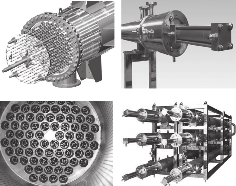
27Heat Exchangers
1.3.8.5 Graphite Heat Exchanger
Impervious graphite as a heat exchanger material is used for the construction of various types of
heat exchangers such as STHE, cubic block heat exchanger, and plate and frame or gasketed heat
exchangers (PHEs). Graphite tubes are used in STHE (refer to Chapter 13) and plates are used in
PHEs (refer to Chapter 7) for special purpose applications. It resists a wide variety of inorganic and
organic chemicals. Graphite heat exchangers are employed as boilers and condensers in the distilla-
tion by evaporation of hydrochloric acid and in the concentration of weak sulfuric acid and of rare
earth chloride solutions. Since cubic heat exchanger cannot be treated in categorization of extended
surface heat exchanger, the same is covered next.
Cubic heat exchanger: It is similar to the compact crossow heat exchanger, consisting of
drilled holes in two perpendicular planes. They are suitable when both the process streams are
corrosive. With a cubic exchanger, a multipass arrangement is possible. It is manufactured by
assembling of accurately machined and drilled graphite plates bonded together by synthetic res-
ins, oven cured and sintered. Gasketed headers with nozzles are assembled on both sides to the
block to form a block heat exchanger and are clamped together, as shown in Figure 1.25.
Modular-block cylindrical exchanger: In this arrangement, solid impervious graphite blocks
have holes drilled in them. These blocks can be multistacked in a cylindrical steel shell that has
(a)
(b)
(c) (d)
FIGURE 1.24 Unicus dynamic scraped surface heat exchanger. (a) 3-D model, (b) hydraulic cylinder head,
(c) a unit of Unicus, and (d) multiple Unicus units. (Courtesy of HRS Heat Exchangers Ltd, Herts, U.K.)
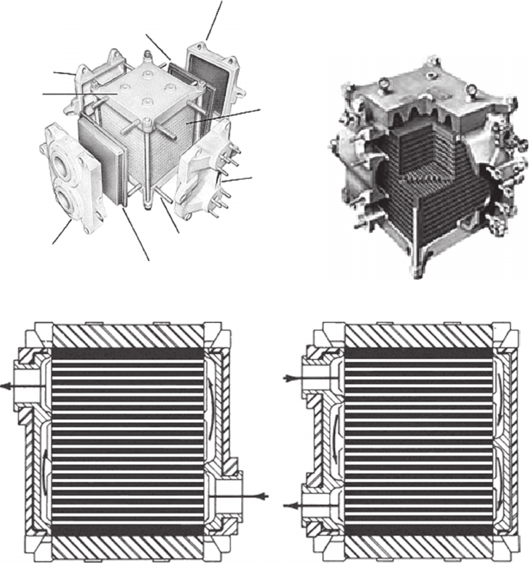
28 Heat Exchanger Design Handbook
glandttings. The process holes are axial and the service holes are transverse. The units are designed
as evaporators and reboilers. A modular block Graphilor
®
exchanger is shown in Figure 1.26.
1.4 SELECTION OF HEAT EXCHANGERS
1.4.1 introduCtion
Selection is the process in which the designer selects a particular type of heat exchanger for a given
application from a variety of heat exchangers. There are a number of alternatives for selecting heat
transfer equipment, but only one among them is the best for a given set of conditions. The heat
exchanger selection criteria are discussed next.
(c) ree passFour pass
Multipass process
return head
Graphite
core
Multipass
inlet/outlet
service head
Process graphite
head liner in/out
Multipass process
inlet/outlet
head
(a)
Clam
ping
plate
Return
service head
Process graphite
return liner
Clamping bolts
Typical flow pattern
(b)
FIGURE 1.25 NK series multipass cubic graphite heat exchanger. (a) Construction details, (b) cut section,
and (c) multipass ow pattern. (Courtesy of MERSEN, Paris La Défense, France.)
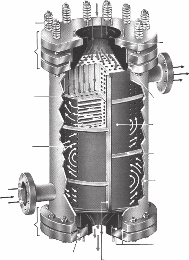
29Heat Exchangers
1.4.2 seleCtion Criteria
Selection criteria are many, but primary criteria are type of uids to be handled, operating pres-
sures and temperatures, heat duty, and cost (see Table 1.1). The uids involved in heat transfer
can be characterized by temperature, pressure, phase, physical properties, toxicity, corrosivity,
and fouling tendency. Operating conditions for heat exchangers vary over a very wide range, and
a broad spectrum of demands is imposed for their design and performance. All of these must be
Coil springs maintain
axial force on heat
exchanger assembly
during operational
temperature changes
Floating end comp
en-
sates for differential
expansion between
graphite core and
steel shell
Drilled axial process
holes (3 diameters
available)
Drilled transverse
service holes
Fixed end
Vertical service fluid drain
(vent and drain are on shell
for horizontal operation)
Stainless steel
longitudinal guide bars
and service baffle
Service fluid gaskets
Steel shell
Elastomeric service
baffles
Graphilor
heat transfer core
(4 diameters available)
Service fluid seal:
TFE packing
Armored floa
ting head
assembly (1 piece
graphite and steel)
FIGURE 1.26 GRAPHILOR
®
cylindrical tubes (in block) heat exchanger. (Courtesy of MERSEN, Paris La
Défense, France.)
30 Heat Exchanger Design Handbook
considered when assessing the type of unit to be used [22]. When selecting a heat exchanger for a
given duty, the following points must be considered:
• Materials of construction
• Operating pressure and temperature, temperature program, and temperature driving force
• Flow rates
• Flow arrangements
• Performance parameters—thermal effectiveness and pressure drops
• Fouling tendencies
• Types and phases of uids
• Maintenance, inspection, cleaning, extension, and repair possibilities
• Overall economy
• Fabrication techniques
• Mounting arrangements: horizontal or vertical
• Intended applications
1.4.2.1 Materials of Construction
For reliable and continuous use, the construction materials for pressure vessels and heat exchangers
should have a well-dened corrosion rate in the service environments. Furthermore, the material should
exhibit strength to withstand the operating temperature and pressure. STHEs can be manufactured in vir-
tually any material that may be required for corrosion resistance, for example, from nonmetals like glass,
Teon, and graphite to exotic metals like titanium, zirconium, tantalum, etc. Compact heat exchangers
with extended surfaces are mostly manufactured from any metal that has drawability, formability, and
malleability. Heat exchanger types like PHEs normally require a material that can be pressed or welded.
1.4.2.2 Operating Pressure and Temperature
1.4.2.2.1 Pressure
The design pressure is important to determine the thickness of the pressure-retaining components.
The higher the pressure, the greater will be the required thickness of the pressure-retaining mem-
branes and the more advantage there is to placing the high-pressure uid on the tubeside. The pres-
sure level of the uids has a signicant effect on the type of unit selected [22].
At low pressures, the vapor-phase volumetric ow rate is high and the low-allowable pressure
drops may require a design that maximizes the area available for ow, such as crossow or
split ow with multiple nozzles.
At high pressures, the vapor-phase volumetric ow rates are lower and allowable pressure
drops are greater. These lead to more compact units.
In general, higher heat transfer rates are obtained by placing the low-pressure gas on the out-
side of tubular surfaces.
Operating pressures of the gasketed PHEs and SPHEs are limited because of the difculty in pressing
the required plate thickness, and by the gasket materials in the case of PHEs. The oating nature of
oating-head shell and tube heat exchangers and lamella heat exchangers limits the operating pressure.
1.4.2.2.2 Temperature
Design temperature: This parameter is important as it indicates whether a material at the design
temperature can withstand the operating pressure and various loads imposed on the component.
For low-temperature and cryogenic applications, toughness is a prime requirement, and for high-
temperature applications the material has to exhibit creep resistance.
Temperature program: Temperature program in both a single-pass and multipass STHE decides
(1) the mean metal temperatures of various components like shell, tube bundle, and tubesheet, and
31Heat Exchangers
(2) the possibility of temperature cross. The mean metal temperatures affect the integrity and capa-
bility of heat exchangers and thermal stresses induced in various components.
Temperature driving force: The effective temperature driving force is a measure of the actual
potential for heat transfer that exists at the design conditions. With a counterow arrangement, the
effective temperature difference is dened by the log mean temperature difference (LMTD). For
ow arrangements other than counterow arrangement, LMTD must be corrected by a correction
factor, F. The F factor can be determined analytically for each ow arrangement but is usually
presented graphically in terms of the thermal effectiveness P and the heat capacity ratio R for each
ow arrangement.
Inuence of operating pressure and temperature on selection of some types of heat exchangers:
The inuence of operating pressure and temperature on selection of STHE, compact heat exchanger,
gasketed PHE, and spiral exchanger is discussed next.
Shell and tube heat exchanger: STHE units can be designed for almost any combination of
pressure and temperature. In extreme cases, high pressure may impose limitations by fabrication
problems associated with material thickness, and by the weight of the nished unit. Differential
thermal expansion under steady conditions can induce severe thermal stresses either in the tube
bundle or in the shell. Damage due to ow-induced vibration on the shellside is well known. In
heat-exchanger applications where high heat transfer effectiveness (close approach temperature) is
required, the standard shell and tube design may require a very large amount of heat transfer sur-
face [23]. Depending on the uids and operating conditions, other types of heat-exchanger design
should be investigated.
Compact heat exchanger: Compact heat exchangers are constructed from thinner materials; they
are manufactured by mechanical bonding, soldering, brazing, welding, etc. Therefore, they are lim-
ited in operating pressures and temperatures.
Gasketed plate heat exchangers and spiral exchangers: Gasketed PHEs and spiral exchangers
are limited by pressure and temperature, wherein the limitations are imposed by the capability of the
gaskets.
1.4.2.3 Flow Rate
Flow rate determines the ow area: the higher the ow rate, the higher will be the crossow
area. Higher ow area is required to limit the ow velocity through the conduits and ow
passages, and the higher velocity is limited by pressure drop, impingement, erosion, and, in
the case of shell and tube exchanger, by shellside ow-induced vibration. Sometimes, a mini-
mum ow velocity is necessary to improve heat transfer to eliminate stagnant areas and to
minimizefouling.
1.4.2.4 Flow Arrangement
As dened earlier, the choice of a particular ow arrangement is dependent upon the required
exchanger effectiveness, exchanger construction type, upstream and downstream ducting, packag-
ing envelope, and other design criteria.
1.4.2.5 Performance Parameters: Thermal Effectiveness and Pressure Drops
Thermal effectiveness: For high-performance service requiring high thermal effectiveness, use
brazed plate-n exchangers (e.g., cryogenic service) and regenerators (e.g., gas turbine applica-
tions), use tube-n exchangers for slightly less thermal effectiveness in applications, and use
shell and tube units for low-thermal effectiveness service.
Pressure drop: Pressure drop is an important parameter in heat exchanger design. Limitations
may be imposed either by pumping cost or by process limitations or both. The heat exchanger
should be designed in such a way that unproductive pressure drop is avoided to the maximum extent
32 Heat Exchanger Design Handbook
in areas like inlet and outlet bends, nozzles, and manifolds. At the same time, any pressure-drop
limitation that is imposed must be utilized as nearly as possible for an economic design.
1.4.2.6 Fouling Tendencies
Fouling is dened as the formation on heat exchanger surfaces of undesirable deposits that impede the
heat transfer and increase the resistance to uid ow, resulting in higher pressure drop. The growth of
these deposits causes the thermohydraulic performance of heat exchanger to decline with time. Fouling
affects the energy consumption of industrial processes, and it also decides the amount of extra mate-
rial required to provide extra heat transfer surface to compensate for the effects of fouling. Compact
heat exchangers are generally preferred for nonfouling applications. In a shell and tube unit, the uid
with more fouling tendencies should be put on the tubeside for ease of cleaning. On the shellside with
cross bafes, it is sometimes difcult to achieve a good ow distribution if the bafe cut is either too
high or too low. Stagnation in any regions of low velocity behind the bafes is difcult to avoid if the
bafes are cut more than about 20%–25%. PHEs and spiral plate exchangers are better chosen for
fouling services. The ow pattern in PHE induces turbulence even at comparable low velocities; in the
spiral units, the scrubbing action of the uids on the curved surfaces minimizes fouling. Also consider
Philips RODbafe heat exchanger, TWISTED TUBE
®
heat exchanger, Helixchanger
®
heat exchanger
or EMbafe
®
heat exchanger to improve ow velocity on shellside, enhance heat transfer performance
and reduce fouling tendencies on shellside.
1.4.2.7 Types and Phases of Fluids
The phase of the uids within a unit is an important consideration in the selection of the heat
exchanger type. Various combinations of uid phases dealt in heat exchangers are liquid–liquid,
liquid–gas, and gas–gas. Liquid-phase uids are generally the simplest to deal with. The high den-
sity and the favorable values of many transport properties allow high heat transfer coefcients to be
obtained at relatively low-pressure drops [4].
1.4.2.8 Maintenance, Inspection, Cleaning, Repair, and Extension Aspects
Consider the suitability of various heat exchangers as regards maintenance, inspection, cleaning, repair,
and extension. For example, the pharmaceutical, dairy, and food industries require quick access to internal
components for frequent cleaning. Since some of the heat exchanger types offer great variations in design,
this must be kept in mind when designing for a certain application. For instance, consider inspection and
manual cleaning. Spiral plate exchangers can be made with both sides open at one edge, or with one side
open and one closed. They can be made with channels between 5 and 25 mm wide, with or without studs.
STHE can be made with xed tubesheets or with a removable tube bundle, with small- or large-diameter
tubes, or small or wide pitch. A lamella heat exchanger bundle is removable and thus fairly easy to clean on
the shellside. Inside, the lamella, however, cannot be drilled to remove the hard fouling deposits. Gasketed
PHEs are easy to open, especially when all nozzles are located on the stationary end-plate side. The plate
arrangement can be changed for other duties within the frame and nozzle capacity.
Repair of some of the shell and tube exchanger components is possible, but the repair of expansion
joint is very difcult. Tubes can be renewed or plugged. Repair of compact heat exchangers of tube-
n type is very difcult except by plugging of the tube. Repair of the plate-n exchanger is generally
very difcult. For these two types of heat exchangers, extension of units for higher thermal duties is
generally not possible. All these drawbacks are easily overcome in a PHE. It can be easily repaired,
and plates and other parts can be easily replaced. Due to modular construction, PHEs possess the
exibility of enhancing or reducing the heat transfer surface area, modifying the pass arrangement,
and addition of more than one duty according to the heat transfer requirements at a future date.
1.4.2.9 Overall Economy
There are two major costs to consider in designing a heat exchanger: the manufacturing cost and the
operating costs, including maintenance costs. In general, the less the heat transfer surface area and less

33Heat Exchangers
the complexity of the design, the lower is the manufacturing cost. The operating cost is the pumping cost
due to pumping devices such as fans, blowers, and pumps. The maintenance costs include costs of spares
that require frequent renewal due to corrosion, and costs due to corrosion/fouling prevention and control.
Therefore, the heat exchanger design requires a proper balance between thermal sizing and pressure drop.
1.4.2.10 Fabrication Techniques
Fabrication techniques are likely to be the determining factor in the selection of a heat transfer
surface matrix or core. They are the major factors in the initial cost and to a large extent inuence
the integrity, service life, and ease of maintenance of the nished heat exchanger [24]. For example,
shell and tube units are mostly fabricated by welding, plate-n heat exchangers and automobile
aluminum radiators by brazing, copper–brass radiators by soldering, most of the circular tube-n
exchangers by mechanical assembling, etc.
1.4.2.11 Choice of Unit Type for Intended Applications
According to the intended applications, the selection of heat exchangers will follow the guidelines
given in Table 1.2.
TABLE 1.2
Choice of Heat Exchanger Type for Intended Applications
Application Remarks
Low-viscosity uids For high temperature/pressures, use STHE or double-pipe heat exchanger. Use
PHE or LHE for low temperature/pressure applications.
Low-viscosity liquid to steam Use STHE in carbon steel.
Medium-viscosity uids Use PHE or with high solids content, use SPHE.
High-viscosity uids PHE offers the advantages of good ow distribution. For extreme viscosities,
the SPHE is preferred.
Fouling liquids Use STHE with removable tube bundle. SPHE or PHE is preferred due to
good ow distribution. Use PHE if easy access is of importance. Also
consider Philips RODbafe heat exchanger, TWISTED TUBE
®
heat
exchanger and Helixchanger
®
heat exchanger, and EMbafe
®
heat exchanger
to improve ow velocity on the shellside, enhance heat transfer performance,
and reduce fouling tendencies on shellside.
Slurries, suspensions, and pulps SPHE offers the best characteristics. Also consider free ow PHE or wide gap
PHE, or scraped surface heat exchanger.
Heat-sensitive liquids PHE fullls the requirements best. Also consider SPHE.
Cooling with air Extended surface types like tube-n heat exchanger or PFHE.
Gas or air under pressure Use STHE with extended surface on the gas side or brazed plate-n exchanger
made of stainless steel or nickel alloys.
Cryogenic applications Brazed aluminum plate-n exchanger, coiled tube heat exchangers, or PCHE.
Vapor condensation Surface condensers of STHE in carbon steel are preferred. Also consider
SPHE or brazed plate heat exchanger.
Vapor/gas partial condensation Choose SPHE.
Refrigeration and air conditioning
applications
Finned tube heat exchangers, special types of PHEs, brazed PHE up to 200°C.
Air–air or gas–gas applications Regenerators and plate-n heat exchangers. Also consider STHE.
Viscous products, aseptic products, jam,
food and meat processing, heat sensitive
products and particulate laden products
Scraped surface heat exchanger.
Note: STHE, shell and tube heat exchanger; PHE, gasketed plate heat exchanger; SPHE, spiral plate heat exchanger; LHE, lamella
heat exchanger; PCHE, printed circuit heat exchangers; CTHE, coiled tube heat exchanger; PFHE, plate-n heat exchanger.
34 Heat Exchanger Design Handbook
1.5 REQUIREMENTS OF HEAT EXCHANGERS
Heat exchangers have to fulll the following requirements:
• High thermal effectiveness
• Pressure drop as low as possible
• Reliability and life expectancy
• High-quality product and safe operation
• Material compatibility with process uids
• Convenient size, easy for installation, reliable in use
• Easy for maintenance and servicing
• Light in weight but strong in construction to withstand the operational pressures and vibra-
tions especially heat exchangers for military applications
• Simplicity of manufacture
• Low cost
• Possibility of effecting repair to maintenance problems
The heat exchanger must meet normal process requirements specied through problem specication
and service conditions for combinations of the clean and fouled conditions, and uncorroded and cor-
roded conditions. The exchanger must be maintainable, which usually means choosing a congura-
tion that permits cleaning as required and replacement of tubes, gaskets, and any other components
that are damaged by corrosion, erosion, vibration, or aging. This requirement may also place limita-
tions on space for tube bundle pulling, to carry out maintenance around it, lifting requirements for
heat exchanger components, and adaptability for in-service inspection and monitoring.
REFERENCES
1. Shah, R. K., Classication of heat exchangers, in Heat Exchangers: Thermal-Hydraulic Fundamentals
and Design (S. Kakac, A. E. Bergles, and F. Mayinger, eds.), Hemisphere, Washington, DC, 1981,
pp. 9–46.
2. Shah, R. K. and Sekulic, D. P., Fundamentals of Heat Exchanger Design, John & Wiley, New York,
2003.
3. Gupta, J. P., Fundamentals of Heat Exchanger and Pressure Vessel Technology, Hemisphere, Washington,
DC, 1986.
4. Walker, G., Cryocoolers, Part 2: Applications, Plenum Press, New York, 1983.
5a. Larowski, A. and Taylor, M. A., Systematic Procedures for Selection of Heat Exchangers, C58/82,
Institution of Mechanical Engineers, London, U.K., 1982, pp. 32–56.
5b. Larowski, A. and Taylor, M. A., Systematic Procedure for Selection of Heat Exchangers, Proc. Inst.
Mech. Eng., 197A, 51–69 (1983).
6. Kern, D. Q., Process Heat Transfer, McGraw-Hill, New York, 1950.
7. Chisholm, D. (ed.), Developments in Heat Exchanger Technology—1, Applied Science Publishers,
London, England, 1980.
8. Minton, P., Process heat transfer, Proceedings of the 9th International Heat Transfer Conference, Heat
Transfer 1990–Jerusalem, Israel, Paper No. KN–2, 1, 355–362 (1990).
9. Timmerhaus, K. D. and Flynn, T. M., Cryogenic Progress Engineering, Plenum Press, New York, 1989.
10. Muoio, J. M., Glass as a material of construction for heat transfer equipment, Industrial Heat Exchangers
Conference Proceedings (A. J. Hayes, W. W. Liang, S. L. Richlen, and E. S. Tabb, eds.), American
Society for Metals, Metals Park, OH, 1985, pp. 385–390.
11. Yilmaz, S. and Samuelson, B., Vertical thermosyphon boiling in spiral plate heat exchangers, in Heat
Transfer—1983, Seattle, Chem. Eng. Prog. Symp. Ser., 79(225), 47–53 (1983).
12. Markovitz, R. E., Picking the best vessel jacket, Chem. Eng., 78(26), 156–162 (1971).
13. Usher, J. D. and Cattell, G. S., Compact heat exchangers, in Developments in Heat Exchanger
Technology—1 (D. Chisholm, ed.), Applied Science Publishers Ltd., London, U.K., 1980, pp.
127–152.
35Heat Exchangers
14. Reay, D. A., Heat exchangers for waste heat recovery, International Research and Development Co., Ltd.,
New Castle upon Tync, U.K., in Developments in Heat Exchanger Technology—1 (D. Chisholm, ed.),
Applied Science Publishers Ltd., London, U.K., 1980, pp. 233–256.
15. Butterworth, D. and Mascone, C. F., Heat transfer heads into the 21 century, Chem. Eng. Prog., September,
30–37 (1991).
16a. Taylor, M. A. (ed), Plate-Fin Heat Exchangers, Guide to Their Specication and Use, HTFS (Harwell
Laboratory), Oxon, U.K., 1980.
16b. ALPEMA, The standards of the Brazed Aluminium Plate-Fin Heat Exchanger Manufacturer’s Association,
3rd ed., Didcot, Oxon, U.K., 2010. (www.alpema.org).
17. API Standard 660, Shell and Tube Exchangers for General Renery Services, 7th edn., American
Petroleum Institute, Washington, DC, 2002.
18a. Steinke, M. E. and Kandlikar, G., Single-phase heat transfer enhancement techniques in microchannel
and minichannel ows, in Microchannels and Minichannels—2004, ASME, Rochester, NY, June 17–19,
2004.
18b. Tuckerman, D. B. and Pease, R. F. W., High-performance heat sinking for VLSI, IEEE Electron Device
Letters, Vol. 2 (5), May 1981, pp. 126–129.
19. Nikitin, K., Kato, Y. and Ngo, L., Thermal-Hydraulic Performance of Printed Circuit Heat Exchanger
in Supercritical CO
2
Cycle, Research Laboratory for Nuclear Reactors, Tokyo Institute of Technology,
Okayama, Tokyo, Japan, 2005.
20. Fleming, R. B., A Compact Perforated Plate Heat Exchanger, in Advances in Cryogenic Engineering,
Vol. 14, Plenum Press, New York, 1969, pp. 196–204.
21. Hendricks, J. B., Perforated plate heat exchanger and method of fabrication, Patent number: 5101894,
Apr 7, 1992.
22. Gollin, M., Heat exchanger design and rating, in Handbook of Applied Thermal Design (E. C. Guyer,
ed.), Chapter 2, Part 7, McGraw-Hill, New York, 1984, pp. 7-24–7-36.
23. Caciula, L. and Rudy, T. M., Prediction of plate heat exchanger performance, D Symp. Ser., Heat
Transfer—1983, Seattle, WA, pp. 76–89.
24. Fraas, A. P. and Ozisik, M. N., Heat Exchanger Design, John Wiley & Sons, New York, 1965.
SUGGESTED READINGS
Bell, K. J. and Mueller, A. C., Wolverine Heat Transfer Data Book II, Wolverine Division of UOP Inc., Decatur,
AL, 1984.
Scaccia, C. and Theoclitus, G., Types, performance and applications, in The Chemical Engineering Guide to
Heat Transfer, Volume I: Plant Principles (K. J. McNaughton and the Staff of Chemical Engineering,
eds.), Hemisphere/McGraw-Hill, New York, 1986, pp. 3–14.
Shah, R. K., Classication of heat exchangers, in Low Reynolds Number Flow Heat Exchangers (S. Kakac,
R. K. Shah, and A. E. Bergles, eds.), Hemisphere, Washington, DC, 1983, pp. 9–19.
Shah, R. K., What’s new in heat exchanger design, ASME, Mech. Eng., 106, 50–59 (1984).
Sukhatme, S. P. and Devotta, S., Classication of heat transfer equipment, in Heat Transfer Equipment
Design (R. K. Shah, E. C. Subbarao, and R. A. Mashelikar, eds.), Hemisphere, Washington, DC,
1988, pp. 7–16.
Thome, R. T., Wolverine Heat Transfer Engineering Data Book III, Wolverine Division of UOP Inc., Decatur,
AL, 2004.
BIBLIOGRAPHY
Afgan, N. H. and Schlunder, E. U. (eds.), Heat Exchangers: Design and Theory Sourcebook, McGraw-Hill,
New York, 1974.
Apblett, W. R. (ed.), Shell and Tube Heat Exchangers, American Society for Metals, Metals Park, OH, 1982.
Bhatia, M. V. and Cheremisinoff, N. P., Heat Transfer Equipment, Process equipment series, Vol. 2, Technomic,
Westport, CT, 1980.
Bryers, R. W. (ed.), Fouling of Heat Exchanger Surfaces, Engineering Foundation, New York, 1983.
Chen, S. S., Flow Induced Vibration of Circular Cylindrical Structures, Hemisphere, Washington, DC,
1987.
Cheremisinoff, N. (ed.), Handbook of Heat and Mass Transfer, Vol. 1—Heat Transfer Operation & Vol. 2—
Mass Transfer and Reactor Design, Gulf Publishing Company, Houston, TX, pp. 767–805, 1986.
36 Heat Exchanger Design Handbook
Cheremisinoff, N. P., Heat Transfer Pocket Handbook, Gulf Publishing Company, Books Division, Houston,
TX, 1984.
Chisholm, D. (ed.), Heat Exchanger Technology, Elsevier Applied Science, New York, 1988.
Effectiveness Ntu Relationships for Design and Performance Evaluation of Multi-pass Crossow Heat
Exchangers, Engineering Sciences Data Unit Item 87020, ESDU International, McLean, VA, October
1987.
Effectiveness Ntu Relationships for Design and Performance Evaluation of Two-Stream Heat Exchangers,
Engineering Sciences Data Unit Item 86018, ESDU International, McLean, VA, July 1986.
Foster, B. D. and Patton, J. B. (eds.), Ceramic Heat Exchangers, American Ceramic Society, Columbus, OH,
1985.
Fraas, A. P., Heat Exchanger Design, 2nd edn., John Wiley & Sons, New York, 1989.
Ganapathy, V., Applied Heat Transfer, PennWell Publishing Co., Tulsa, OK, 1982.
Garrett-Price, B. A., Smith, S. A., Watts, R. L., Knudsen, J. C., Marner, W. J., and Suitor, J. W., Fouling of Heat
Exchangers, Noyes, Park Ridge, NJ, 1985.
Hayes, A. J., Liang, W. W., Richlen, S. L., and Tabb, E. S. (eds.), Industrial Heat Exchangers Conference
Proceedings, American Society for Metals, Metals Park, OH, 1985.
Hewitt, G. F. (coordinating editor), Hemisphere Handbook of Heat Exchanger Design, Hemisphere, New York,
1990.
Hewitt, G. F., Shires, G. L., and Bott, T. R., Process Heat Transfer, CRC Press, Boca Raton, FL, 1994.
Hewitt, G. F. and Whalley, P. B., Handbook of Heat Exchanger Calculations, Hemisphere, Washington, DC,
1989.
Hryniszak, W., Heat Exchangers: Application to Gas Turbines, Butterworth Scientic Publications, London,
U.K., 1958.
Hussain, H., Heat Transfer in Counterow, Parallel Flow and Cross Flow, McGraw-Hill, New York, 1982.
Jakob, M., Heat Transfer, John Wiley & Sons, New York, 1957.
Kakac, S., Bergles, A. E., and Fernandes, E. O. (eds.), Two-Phase Flow Heat Exchangers: Thermal Hydraulic
Fundamentals and Design, Kluwer Academic Publishers, Dordrecht, the Netherlands, 1988.
Kakac, S., Bergles, A. E., and Mayinger, F. (eds.), Heat Exchangers: Thermal-Hydraulic Fundamentals and
Design, Hemisphere/McGraw-Hill, Washington, DC, 1981.
Kakac, S., Shah, R. K., and Aung, W. (eds.), Handbook of Single Phase Convective Heat Transfer, John Wiley &
Sons, New York, 1987.
Kakac, S., Shah, R. K., and Bergles, A. E. (eds.), Low Reynolds Number Flow Heat Exchangers, Hemisphere,
Washington, DC, 1983.
Kays, W. M. and London, A. L., Compact Heat Exchangers, 3rd edn., McGraw-Hill, New York, 1984.
Kern, D. Q. and Kraus, A. D., Extended Surface Heat Transfer, McGraw-Hill, New York, 1972, pp. 439–641.
Kraus, A. D., Analysis and Evaluation of Extended Surface Thermal Systems, Hemisphere, Washington, DC,
1982.
Levenspiel, O., Engineering Flow and Heat Exchange, Plenum Press, New York, 1984.
Mahajan, K. K., Design of Process Equipments, Pressure Vessel Handbook Publishing Company, Tulsa, OK,
1985.
Manzoor, M., Heat Flow through Extended Surface Heat Exchangers, Springer-Verlag, Berlin, Germany, 1984.
Martin, H., Heat Exchangers, Hemisphere, Washington, DC, 1992.
McNaughton, K. J. and the Staff of Chemical Engineering (eds.), The Chemical Engineering Guide to Heat
Transfer: Vol. I: Plant Principles, Vol. II: Equipment, Hemisphere/McGraw-Hill, New York, 1986.
Melo, L. F., Bott, T. R., and Bernardo, C. A. (eds.), Advances in Fouling Science and Technology, Kluwer
Academic Publishers, Dordrecht, the Netherlands, 1988.
Mondt, J. R., Regenerative Heat Exchangers: The Elements of Their Design, Selection and Use, Research
Publication GMR-3396, General Motors Research Laboratories, Warren, MI, 1980.
Mori, Y., Sheindlin, A. E., and Afgan, N. H. (eds.), High Temperature Heat Exchangers, Hemisphere,
Washington, DC, 1986.
Palen, J. W. (ed.), Heat Exchanger Sourcebook, Hemisphere, Washington, DC, 1987.
Perry, R. H. and Chilton, C. H. (eds.), Chemical Engineers’ Handbook, 5th edn., McGraw-Hill, New York,
1973.
Reay, D. A., Heat Recovery Systems, E. and F. N. Spon Ltd., London, U.K., 1979.
Rohsenow, W. M., Hartnett, J. P., and Ganic, E. N. (eds.), Handbook of Heat Transfer Applications, McGraw-Hill,
New York, 1985.
Saunders, E. A. D., Heat Exchangers: Selection, Design and Construction, Addison Wesley Longman, Reading,
MA, 1989.
37Heat Exchangers
Schlunder, E. U. (editor-in-chief), Heat Exchanger Design Handbook, in ve volumes (Vol. 1—Heal
Exchanger Theory, Vol. 2—Fluid Mechanics and Heat Transfer, Vol. 3—Thermal and Hydraulic Design
of Heat Exchangers, Vol. 4—Mechanical Design of Heat Exchangers, and Vol. 5—Physical Properties),
Hemisphere, Washington, DC, 1983.
Schmidt, F. W. and Willmott, A. J., Thermal Energy Storage and Regeneration, Hemisphere/McGraw-Hill,
Washington, DC, 1981.
Shah, R. K., Kraus, A. D., and Metzger, D. (eds.), Compact Heat Exchangers—A Festschrift for A. L. London,
Hemisphere, Washington, DC, 1990, pp. 31–90.
Shah, R. K. and London, A. L., Laminar Flow Forced Convection in Ducts, Supplement 1 to advances in heat
transfer series, Academic Press, New York, 1978.
Shah, R. K. and Mueller, A. C., Heat exchanger, in Ullmann’s Encyclopedia of Industrial Chemistry, Unit
Operations II, Vol. B3, Chapter 2, VCH Publishers, Weinheim, Germany, 1989.
Shah, R. K., Subbarao, E. C., and Mashelkar, R. A. (eds.), Heat Transfer Equipment Design, Hemisphere,
Washington, DC, 1988.
Sheindlin, A. E. (ed.), High Temperature Equipment, Hemisphere, Washington, DC, 1986.
Singh, K. P. and Soler, A. I., Mechanical Design of Heat Exchangers and Pressure Vessel Components, Arcturus
Publishers, Cherry Hill, NJ, 1984.
Somerscales, E. F. C. and Knudsen, J. G. (eds.), Fouling of Heat Transfer Equipment, Hemisphere/McGraw-
Hill, Washington, DC, 1981.
Stasiulevicius, J. and Skrinska, A., Heat Transfer of Finned Tube Bundles in Crossow, Hemisphere,
Washington, DC, 1987.
Taborek, J., Hewitt, G. F., and Afgan, N. (eds.), Heat Exchangers: Theory and Practice, Hemisphere/McGraw-
Hill, Washington, DC, 1983.
Walker, G., Industrial Heat Exchangers—A Basic Guide, Hemisphere/McGraw-Hill, New York, 1982.
Yokell, S., A Working Guide to Shell and Tube Heat Exchangers, McGraw-Hill, New York, 1990.
Zukauskas, A. A., High Performance Single-Phase Heat Exchangers (J. Karni, English edition editor),
Hemisphere, Washington, DC, 1989.
Zukauskas, A. and Ulinskas, R., Heat Transfer in Tube Banks in Crossow, Hemisphere, Washington, DC,1988.

39
2
Heat Exchanger
Thermohydraulic
Fundamentals
2.1 HEAT EXCHANGER THERMAL CIRCUIT ANDOVERALL
CONDUCTANCE EQUATION
In order to develop relationships between the heat transfer rate q, surface area A, uid terminal
temperatures, and ow rates in a heat exchanger, the basic equations used for analysis are the energy
conservation and heat transfer rate equations [1]. The energy conservation equation for an exchanger
having an arbitrary ow arrangement is
qCtt Ct t=−=−
hh,i h,occ,oc,i
()()
(2.1)
and the heat transfer rate equation is
qUAt
t
R
==
∆
∆
m
m
o
(2.2)
where
∆t
m
is the true mean temperature difference (MTD), which depends upon the exchanger ow
arrangement and the degree of uid mixing within each uid stream
C
c
is the capacity rate of the cold uid, (Mc
p
)
c
C
h
is the capacity rate of the hot uid, (Mc
p
)
h
t
c,i
and t
c,o
are cold uid terminal temperatures (inlet and outlet)
t
h,i
and t
h,o
are hot uid terminal temperatures (inlet and outlet)
The heat exchanger thermal circuit variables and overall conduction described here are based on
Refs. [1,2].
The inverse of the overall thermal conductance UA is referred to as the overall thermal resistance
R
o
, and it is made up of component resistances in series as shown in Figure 2.1:
RRRR RR
o h1w2c
=++++
(2.3)
where the parameters of the right-hand side of Equation 2.3 are R
h
, hot side lm convection resis-
tance, 1/(η
o
hA)
h
; R
1
, thermal resistance due to fouling on the hot side given in terms of fouling
resistance R
f,h
(i.e., values tabulated in standards or textbooks), R
f,h
/(η
o
A)
h
; R
w
, thermal resistance of
the separating wall, expressed for a at wall by
R
Ak
w
ww
=
δ
(2.4a)
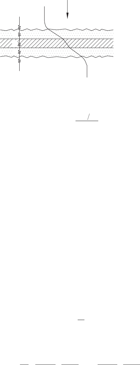
40 Heat Exchanger Design Handbook
and for a circular wall by
R
dd
kLN
w
i
wt
ln
=
()
2
π
(2.4b)
where
δ is the wall thickness
A
w
is the total wall area for heat conduction
k
w
is the thermal conductivity of the wall material
d is the tube outside diameter
d
i
is the tube inside diameter
L is the tube length
N
t
is the number of tubes, and total wall area for heat conduction is given by
ALLL
wp
=
12
(2.5)
where
L
1
, L
2
, and N
p
are the length, width, and total number of separating plates, respectively
R
2
is the thermal resistance due to fouling on the cold side, given in terms of cold side fouling
resistance R
f,c
by R
f,c
/(η
o
A)
c
R
c
is the cold side lm convection resistance, 1/(η
o
hA)
c
In these denitions, h is the heat transfer coefcient on the side under consideration, A represents
the total of the primary surface area, A
p
, and the secondary (nned) surface area, A
f
, on the uid side
under consideration, η
o
is the overall surface effectiveness of an extended surface, and the subscripts
h and c refer to the hot and cold uid sides, respectively. The overall surface effectiveness η
o
is related
to the n efciency η
f
and the ratio of n surface area A
f
to total surface area A as follows:
ηη
o
f
f
=− −
11
A
A
()
(2.6)
Note that η
o
is the unity for an all prime surface exchanger without ns. Equation 2.3 can be alternately
expressed as
11 1
UA hA
R
A
R
hA
R
A
=+++ +
() ()
ηη
ηη
oh
f,h
oh
w
oc
f,c
oc
() ()
(2.7)
Laminar sublayer
q
q
h
, C
h
, T
h
T
c
, C
c
, q
c
Laminar sublayer
Fouling layer
Fouling layer
Heat transfer surfa
ce
R
h
R
1
R
w
R
2
R
c
FIGURE 2.1 Elements of thermal resistance of a heat exchanger.

41Heat Exchanger Thermohydraulic Fundamentals
Since UA = U
h
A
h
= U
c
A
c
, the overall heat transfer coefcient U as per Equation 2.7 may be dened
optionally in terms of either hot uid surface area or cold uid surface area. Thus, the option of A
h
or
A
c
must be specied in evaluating U from the product, UA. For plain tubular exchangers, U
o
based
on tube outside surface is given by
11
2Uh
R
ddd
k
Rd
d
d
hd
oo
f,o
i
w
f,i
iii
/
=+ +++
ln()
(2.8)
The knowledge of wall temperature in a heat exchanger is essential to determine the localized hot
spots, freeze points, thermal stresses, local fouling characteristics, or boiling and condensing coef-
cients. Based on the thermal circuit of Figure 2.1, when R
w
is negligible, T
w,h
= T
w,c
= T
w
is computed
from [1,2] as
T
TTRRRR
RRRR
w
hch1 c
hc2
/
/
=
++ +
[]
++ +
[]
()()
()
()
2
1
1
(2.9)
When R
1
= R
2
= 0, Equation 2.9 further simplies to
T
TR TR
RR
hA ThAT
hA hA
w
hh cc
hc
ohho
cc
oh oc
//
//
=
+
+
=
+
+
11
() ()
()()
ηη
ηη
(2.10)
2.2 HEAT EXCHANGER HEAT TRANSFER ANALYSIS METHODS
2.2.1 energy BalanCe equation
The rst law of thermodynamics must be satised in any heat exchanger design procedure at
both the macro and microlevels. The overall energy balance for any two-uid heat exchanger
is given by
mc tt mc tt
hp,h h,ih,o cp,c c,
oc
,i
() ()−= −
(2.11)
Equation 2.11 satises the “macro” energy balance under the usual idealizations made for the basic
design theory of heat exchangers [3].
2.2.2 heat transfer
For any ow arrangement, heat transfer for two uid streams is given by
qCtt Ct t=−=−
hh,i h,occ,oc,i
()()
(2.12)
and the expression for maximum possible heat transfer rate q
max
is
qCtt
max min
()=−
h,ic,i
(2.13)
The maximum possible heat transfer rate would be obtained in a counterow heat exchanger with
very large surface area and zero longitudinal wall heat conduction, and the actual operating condi-
tions are the same as the theoretical conditions.

42 Heat Exchanger Design Handbook
2.2.3 BasiC methods to CalCulate thermal effeCtiveness
There are four design methods to calculate the thermal effectiveness of heat exchangers:
1. ε-NTU method
2. P-NTU
t
method
3. LMTD method
4. ψ-P method
The basics of these methods are discussed next. For more details on these methods, refer to
Refs. [1,2].
2.2.3.1 ε-NTU Method
The formal introduction of the ε-NTU method for the heat exchanger analysis was in 1942 by
London and Seban [4]. In this method, the total heat transfer rate from the hot uid to the cold uid
in the exchanger is expressed as
qCtt=−ε
min
()
h,ic,i
(2.14)
where ε is the heat exchanger effectiveness. It is nondimensional and for a direct transfer type heat
exchanger, in general, it is dependent on NTU, C*, and the ow arrangement:
ε=φ
(,
*
,)NTUflowarrangementC
(2.15)
These three nondimensional parameters, C*, NTU, and ε, are dened next.
Heat capacity rate ratio, C*: This is simply the ratio of the smaller to larger heat capacity rate
for the two uid streams so that C* ≤ 1.
C
C
C
mc
mc
*
()
()
min
max
min
max
==
p
p
(2.16)
where
C refers to the product of mass and specic heat of the uid
the subscripts min and max refer to the C
min
and C
max
sides, respectively
In a two-uid heat exchanger, one of the streams will usually undergo a greater temperature change
than the other. The rst stream is said to be the “weak” stream, having a lower thermal capacity rate
(C
min
), and the other with higher thermal capacity rate (C
max
) is the “strong” stream.
Number of transfer units, NTU: NTU designates the nondimensional “heat transfer size” or
“thermal size” of the exchanger. It is dened as a ratio of the overall conductance to the smaller
heat capacity rate:
NTU ==
∫
UA
CC
UdA
A
min min
1
(2.17)
If U is not a constant, the denition of the second equality applies. For constant U, substitution of
the expression for UA results in [1,2]
NTU
//
oh
wo
c
=
++ ++
11
11
12
ChARRR hA
min
()
()ηη
(2.18)

43Heat Exchanger Thermohydraulic Fundamentals
where R
1
and R
2
are the thermal resistances due to fouling on the hot side and the cold side, respec-
tively, as dened in Equation 2.7. In the absence of the fouling resistances, NTU can be given by
the expression
11 1
NTUNTU /NTU /
hh
w
cc
=++
() ()
min
min
min
CC
RC
CC
(2.19)
and the number of heat transfer units on the hot and cold sides of the exchanger may be dened as
follows:
NUT NTU
h
oh
h
c
oc
c
==
() ()ηηhA
C
hA
C
(2.20)
Heat exchanger effectiveness, ε: Heat exchanger effectiveness, ε, is dened as the ratio of the actual
heat transfer rate, q, to the thermodynamically possible maximum heat transfer rate (q
max
) by the
second law of thermodynamics:
ε=
q
q
max
(2.21)
The value of ε ranges between 0 and 1. Using the value of actual heat transfer rate q from Equation
2.12 and q
max
from Equation 2.13, the exchanger effectiveness ε of Equation 2.21 is given by
ε=
−
−
=
−
−
Ct t
Ct t
Ct t
Ct t
hh,i h,o
h,ic,i
cc,o c,i
h,
ic
,i
()
()
()
(
min min
))
For
*
,
hc
C
==
1
εε
(2.22)
Dependence of ε on NTU: At low NTU, the exchanger effectiveness is generally low. With increas-
ing values of NTU, the exchanger effectiveness generally increases, and in the limit it approaches
the maximum asymptotic value. However, there are exceptions such that after reaching a maximum
value, the effectiveness decreases with increasing NTU.
2.2.3.2 P-NTU
t
Method
This method represents a variant of the ε-NTU method. The origin of this method is related to shell
and tube exchangers. In the ε-NTU method, one has to keep track of the C
min
uid. In order to avoid
possible errors, an alternative is to present the temperature effectiveness, P, of the uid side under
consideration as a function of NTU and heat capacity rate of that side to that of the other side, R.
Somewhat arbitrarily, the side chosen is the tubeside regardless of whether it is the hot side or the
cold side.
General P-NUT
t
functional relationship: Similar to the exchanger effectiveness ε, the thermal
effectiveness P is a function of NTU
t
, R, and ow arrangement:
PR=φ(,,)NTUflowarrangement
t
(2.23)
where P, NTU
t
, and R are dened consistently based on the tubeside uid variables. In this method,
the total heat transfer rate from the hot uid to the cold uid is expressed by
qPCT t=−
t1 1
()
(2.24)

44 Heat Exchanger Design Handbook
Thermal effectiveness, P: For a shell and tube heat exchanger, the temperature effectiveness of
the tubeside uid, P, is referred to as the “thermal effectiveness.” It is dened as the ratio of the
temperature rise (drop) of the tubeside uid (regardless of whether it is hot or cold uid) to the dif-
ference of inlet temperature of the two uids. According to this denition, P is given by
P
tt
Tt
P=
−
−
21
1
is referred to tubeside
1
()
(2.25)
where
t
1
and t
2
refer to tubeside inlet and outlet temperatures, respectively
T
1
and T
2
refer to shellside inlet and outlet temperatures, respectively
Comparing Equations 2.25 and 2.22, it is found that the thermal effectiveness P and the exchanger
effectiveness ε are related as
P
C
C
CC
CCC
== =
==
min
min
max
t
t
t
for
*for
εε
ε
(2.26)
Note that P is always less than or equal to ε. The thermal effectiveness of the shellside uid can be
determined from the tubeside values by the relationship given by
PP
C
C
PR
RPP
t
s
s
(tubeside)
==
==For
*
,
s
1
(2.27)
(For TEMA shell types, the thermal effectiveness charts given in this chapter 2, depicts thermal
effectiveness referred to tubeside only)
Heat capacity ratio, R: For a shell and tube exchanger, R is the ratio of the capacity rate of the tube
uid to the shell uid. This denition gives rise to the following relation in terms of temperature
drop (rise) of the shell uid to the temperature rise (drop) of the tube uid:
R
C
C
TT
tt
==
−
−
t
s
12
21
(2.28)
where the right-hand-side expressions come from an energy balance and indicate the temperature drop/
rise ratios. The value of R ranges from zero to innity, zero being for pure vapor condensation and inn-
ity being for pure liquid evaporation. Comparing Equations 2.28 and 2.16, R and C
*
are related by
R
C
C
CCC
C
CC
== =
==
t
s
t
t
for
for
*
*
min
max
1
(2.29)
Thus R is always greater than or equal to C*.
Number of transfer units, NTU
t
: For a shell and tube exchanger, the number of transfer units
NTU
t
is dened as a ratio of the overall conductance to the tubeside uid heat capacity rate:
NTU
t
t
=
UA
C
(2.30)

45Heat Exchanger Thermohydraulic Fundamentals
Thus, NTU
t
is related to NTU based on C
min
by
NTUNTU NTUfor
NTUfor
t
t
t
t
== =
==
C
C
CC
CCC
min
min
max
*
(2.31)
Thus NTU
t
is always less than or equal to NTU.
2.2.3.3 Log Mean Temperature Difference Correction Factor Method
The maximum driving force for heat transfer is always the log mean temperature difference
(LMTD) when two uid streams are in countercurrent ow. However, the overriding importance
of other design factors causes most heat exchangers to be designed in ow patterns different
from true countercurrent ow. The true MTD of such ow arrangements will differ from the
logarithmic MTD by a certain factor dependent on the ow pattern and the terminal tempera-
tures. This factor is usually designated as the log MTD correction factor, F. The factor F may
be dened as the ratio of the true MTD to the logarithmic MTD. The heat transfer rate equation
incorporating F is given by
qUAt UAFt==∆∆
ml
m
(2.32)
where
∆t
m
is the true MTD
∆t
lm
is the LMTD
The expression for LMTD for a counterow exchanger is given by
LMTD
ln
lm
=∆ =
∆−∆
∆∆
t
tt
tt
12
12
()
(2.33a)
where ∆t
1
= t
h,i
− t
c,o
= T
1
− t
2
and ∆t
2
= t
h,o
− t
c,i
= T
2
− t
1
for all ow arrangements except for paral-
lelow; for parallelow ∆t
1
= t
h,i
− t
c,i
(=T
1
− t
1
) and ∆t
2
= t
h,o
− t
c,o
(=T
2
− t
2
). Therefore, LMTD can be
represented in terms of the terminal temperatures, that is, greater terminal temperature difference
(GTTD or GTD) and smaller terminal temperature difference (STTD or STD) for both pure paral-
lel- and counterow arrangements. Accordingly, LMTD is given by
LMTD
GTTD STTD
ln GTTD/STTD
lm
=∆ =
−
t
()
(2.33b)
The terminal temperature distribution to calculate LMTD is shown in Figure 2.2a.
2.2.3.3.1 LMTD Correction Factor, F
Charts to determine LMTD from the terminal temperature differences are shown in Figure 2.2b.
(Note: While referring the nomogram of Figure 2.2b, use GTD in place of GTTD and STD in place
of STTD.)
From its denition, F is expressed by
F
t
t
=
∆
∆
m
lm
(2.34)
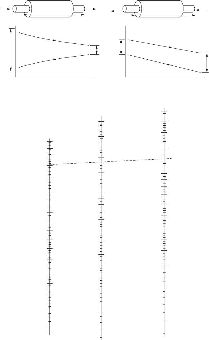
46 Heat Exchanger Design Handbook
t
1
∆t
2
∆t
2
∆t
1
∆t
1
t
1
1. Parallelflow(a) 2. Counterflow
Temperature distribution along
the length of heat exchanger
Temperature distribution along
the length of heat exchanger
Temperature
Temperature
t
1
t
2
t
2
t
2
T
2
T
2
T
2
T
1
t
2
t
1
T
2
T
1
T
1
T
1
400
400
350
300
250
150
100
90
80
70
60
50
40
30
20
∆t
1
GTD
∆t
1
Greatest temperature difference (GTD) °F
∆t
m
Log mean temperature difference (LMTD) °F
∆t
2
Least temperature difference (LTD) °F
100
90
80
70
60
50
40
30
20
100
90
80
70
60
50
40
30
20
10
(b)
∆t
2
LTDLMTD
10
9
8
7
6
10
9
8
7
6
5
4
200
300
250
150
200
300
250
150
200
FIGURE 2.2 (a) Terminal temperature to calculate LMTD; (b) nomogram to nd LMTD. (Courtesy of
Paul-Muller Company, Springeld, MO.)

47Heat Exchanger Thermohydraulic Fundamentals
In situations where the heat release curves are nonlinear, the approach just described is not appli-
cable and a “weighted” temperature difference must be determined.
It can be shown that, in general, F is dependent upon the thermal effectiveness P, the heat capac-
ity rate ratio R, and the ow arrangement. Therefore, F is represented by
FPR=φ(,,, )NTUflowarrangement
t
(2.35)
and the expression for F in terms of P, R, and NTU is given by
F
R
P
PR
R
P
P
R
=
−
−
−
≠
=
−
=
1
1
1
1
1
1
1
()
()
NTU
ln for
NTU
for
(2.36a)
F
C
C
C
C
=
−
−
−
≠
=
−
=
1
1
1
1
1
1
1
(*)
*
*
(
*
NTU
ln for
)NTU
for
ε
ε
ε
ε
(2.36b)
The factor F is dimensionless.
The value of F is unity for a true counterow exchanger, and thus independent of P and R.
For other arrangements, F is generally less than unity, and can be explicitly presented as a func-
tion of P, R, and NTU
t
by Equation 2.36. The value of F close to unity does not mean a highly
efcient heat exchanger, but it means a close approach to the counterow behavior for the com-
parable operating conditions of ow rates and inlet uid temperatures. Because of a large capital
cost involved with a shell and tube exchanger, generally it is designed in the steep region of the
P-NTU
t
curve (ε-NTU relation for the compact heat exchanger) (ε or P < 60%), and as a rule of
thumb, the F value selected is 0.80 and higher. However, a better guideline for F
min
is provided
in the next section. For more details on heat exchanger thermal design methods, refer to Shah
and Sekulic [5] and Ref. [6].
2.2.3.3.2 Approximate F Value for Heat Exchanger Sizing Purpose
This correction factor accounts for the two streams not in counterow. At the estimation stage, we do
not know the detailed ow and pass arrangement so we can assume the following for preliminary sizing:
• F = 1.0 for true counterow, e.g., double-pipe heat exchanger in counterow arrangement,
F shell type of shell and tube heat exchanger
• F = 0.7 for crossow heat exchanger
• F = 0.7 for TEMA E shell with single pass on both shellside and tubeside
• F = 0.80 for E
1–2
shell and tube heat exchanger (refer Figure 2.28)
• F = 0.95 for G
1–2
(refer Figure 2.34), H
1–2
shell and tube heat exchanger (refer Figure 2.36)
• F = 0.79 for J
1–2
shell and tube heat exchanger (refer Figure 2.38)
• F = 0.9 for multi-pass compact heat exchanger and multiple passes on both shellside and
tubeside of TEMA E shell
• F = 1.0 if one stream is isothermal, C* = 0, R = 0 or ∞ (typically boiling or condensation)
Applicability of ε-NTU and LMTD methods: Generally, the ε-NTU method is used for the design
of compact heat exchangers. The LMTD method is used for the design of shell and tube heat
exchangers. It should be emphasized that either method will yield the identical results within the
convergence tolerances specied.

48 Heat Exchanger Design Handbook
2.2.3.4 ψ-P Method
The ψ-P method was originally proposed by Smith [7] and modied by Mueller [8]. In this method,
a new term ψ is introduced, which is expressed as the ratio of the true MTD to the inlet temperature
difference of the two uids:
ψ=
∆
−
=
∆
−
t
tt
t
Tt
m
h,ic,i
m
11
(2.37)
and ψ is related to ε and NTU and P and NTU
t
as
ψ
ε
==
NTUNTU
t
P
(2.38)
and the heat transfer rate is given by
qUAt t=−ψ()
h,
ic
,i
(2.39a)
=−UA Ttψ()
11
(2.39b)
Since ψ represents the nondimensional ∆t
m
, there is no need to compute ∆t
lm
in this method.
Functional relationship between the various thermal design methods: The general functional
relationship for the ε-NTU, P-NTU
t
, LMTD, and ψ-P methods is shown in Table 2.1, which has
been adapted and modied from Ref. [1], and the relationship between the dimensionless groups of
these methods is given in Table 2.2.
Thermal design methods for the design of shell and tube heat exchangers: Any of the four meth-
ods (ε-NTU, P-NTU
t
, LMTD, and ψ-P) can be used for shell and tube exchangers.
TABLE 2.1
General Functional Relationship between Dimensionless Groups of the ε-NTU, P-NTU
t
,
and LMTD
Heat Transfer
Parameters ε-NTU Method P-NTU
t
Method LMTD Method
Heat capacity rate
ratio
C
C
C
mc
mc
*
()
()
min
max
min
max
==
p
p
R
C
C
TT
tt
==
−
−
t
s
12
21
LMTD
=
−
∆∆
∆
∆
tt
t
t
12
1
2
ln
NTU
NT
U
A
==
∫
UA
CC
UdA
min min
1
NTU
t
t
=
UA
C
LMTD = ∆t
lm
F = ϕ (P, R, NTU
t
, ow arrangement)
Thermal
effectiveness
ε = ϕ(NTU, C*, ow
arrangement)
P = ϕ(NTU
t
, R, ow
arrangement)
F
t
t
=
∆
∆
m
lm
F
R
P
PR
R
P
P
R
=
−
−
−
≠
=
−
=
1
1
1
1
1
1
1
()
()
NTU
ln for
NTU
for
qUAt UAFt
==
∆∆
mlm
ε
=
hh,i h,o
h,ic,i
cc,o c,i
h,ic,i
Ct t
Ct t
Ct t
Ct t
()
()
()
(
min min
−
−
=
−
−
))
P
tt
Tt
=
−
−
21
11
PP
C
C
PR
s
t
s
==
Heat transfer
qCtt Ct t=−=−
hh,i h,occ,oc,i
()()
qPCT t=−
t1 1
()

49Heat Exchanger Thermohydraulic Fundamentals
2.2.4 some fundamental relationshiPs to CharaCterize
theexChanger for “suBdesign” Condition
The partial derivatives of the temperature efciency P with respect to NTU and R enable complete
characterization of the exchanger performance around an operating point. Thus, the exchanger per-
formance can be readily predicted for the “subdesign” conditions [9]. Singh [9] developed deriva-
tives of P, F, and NTU. Derivatives for P and F are discussed next.
Dependence of thermal effectiveness: Thermal performance P and thermal effectiveness ε can
be represented through R by [9]
ε
>
=≤
=
PR
PR R
1
1
(2.40)
Pf R= (,)NTU
(2.41)
εφ()= NTUR,*
(2.42)
Thus,
dd d
R
dRεφ
φφ
==
∂
∂
+
∂
∂NTU
NTU
(2.43)
ddP
P
d
P
R
dR Rε= =
∂
∂
+
∂
∂
≤
NTU
NT
Uf
or 1
(2.44)
dPdR RdPε= +
(2.45)
=+
∂
∂
+
∂
∂
PdRR
P
d
P
R
dR
NTU
NTU
(2.46)
TABLE 2.2
Relationship between Dimensionless Groups
of the ε-NTU, P-NTU
t
, and LMTD Methods
R
C
C
CCC
C
CC
== =
==
t
s
t
t
for*
*
for
min
max
1
NTUNTU NTUfor
NTUfor
tt
t
== =
==
C
C
CC
CCC
min
t
min
max
*
F
R
P
PR
R
P
P
R
P
=
−
−
−
≠
=
−
=
==
1
1
1
1
1
1
1
()
ln
()
NTU
for
NTU
for
NTUNT
ψ
ε
UU
t

50 Heat Exchanger Design Handbook
or
dPR
P
R
dR R
P
dRε≥
=+
∂
∂
+
∂
∂
NTU
NTUfor 1
(2.47)
Dependence of LMTD correction factor, F: The derivatives of F with respect to ε, P, and R are
given by [9]
∂
∂
=−
−
−
−
=
−
F
R
P
PR
F
NTUNTU
ln
NTU
1
1
1
1
2
()
(2.48)
∂
∂
=
−−
F
PPPR
1
11NTU( )( )
(2.49)
∂
∂
=
−
−
+
−−
F
R
F
RRPR() ()()1
1
11NTU
(2.50)
and
dF
F
P
dP
F
d
F
R
dR=
∂
∂
+
∂
∂
+
∂
∂NTU
NTU
(2.51)
2.3 THERMAL EFFECTIVENESS CHARTS
Broadly speaking, there are two types of heat exchanger problems: rating and sizing. To solve either
type of problem from rst principles is laborious and time-consuming. However, sizing and rating
of heat exchangers are solved with the use of performance charts easily. The graphical charts were
introduced many years ago and have gained wide acceptance throughout the industry. Five types of
heat exchanger design charts are found in the literature, and the salient features of these charts are
discussed by Turton et al. [10]. These charts are shown schematically in Figure 2.3a–f. The dimen-
sionless variables used in these charts (ε, P, R, C*, F, NTU, NTU
t
) have been dened in Section 2.2.
Figure 2.3a is the most widely used of these charts and was introduced by Bowman et al. [11] in
1940. In this chart, the LMTD correction factor, F, is presented as a function of the effectiveness, P,
and the heat capacity rate ratio, R. Using this chart, the design problem where terminal temperatures
and ow rates are usually specied but overall U and/or A are unknown can be solved; however,
the rating problem can be solved by a trial-and-error solution. Since F compares the true MTD of a
given ow arrangement with that of the counterow arrangement, these charts provide a well-suited
means of nding out the best of several possible ow arrangements. The one with the higher F will
require the lower NTU, that is, the lower area if U remains constant, operating with the same R and
P. Underwood [12] rst derived the expression for true MTD for E
1–2
, E
1–4
, and E
2–4
shell and tube
exchangers in 1934. Bowman et al. [11] published a summary of correction factors for exchangers of
different ow arrangements. Ten Broeck [13] further constructed charts using dimensionless groups,
UA/(mc
p
)
t
, P = (t
2
− t
1
)/(T
1
− t
1
), and R = (T
1
− T
2
)/(t
2
− t
1
) for direct calculation of terminal temperatures
with known surface area of a heat exchanger. At present, F charts are available for all TEMA shells.
Figure 2.3b and c are due to Kays and London [14] and TEMA [15], respectively. Figure 2.3c
is plotted on a semilog paper, since the most useful NTU and NTU, design range for compact
heat exchangers and shell and tube exchangers, respectively, is 0.2–3.0. A careful look at the lin-
ear graphical presentation of the ε-NTU results of Figure 2.3b indicates that the NTU scale in
this range is short and hence one cannot obtain the accurate values of ε or NTU from graphs.
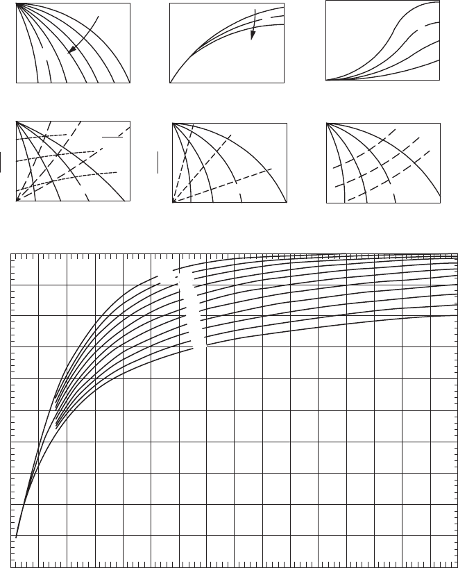
51Heat Exchanger Thermohydraulic Fundamentals
Forbetter appreciation, this is illustrated through the thermal relation chart (ε-NTU) for crossow
heat exchanger in Figure 2.3. An alternative is to stretch the NTU scale in the range 0.2–3.0 by using
a logarithmic scale. Thus, the P-NTU
t
results are generally presented on a semilog paper, as shown
for example in Figure 2.3c, in order to obtain more accurate graphical values of P or NTU
t
. Using
these charts, both the sizing and rating problem can be solved. However, the LMTD correction fac-
tor F is not shown in these charts. Hence, it is to be calculated additionally.
Muller [8] proposed the charts of Figure 2.3d with its triple family of curves. This chart can be
used to solve both the sizing and rating problems and in addition gives the F values. However, Figure
2.3d is somewhat cramped and difcult to read accurately and introduces yet another parameter,
1
0
0.1 1.0
10
P
R
NTU(c)
1
1
0
0
P
R
F
NTU
P
NTU
1
(d)
1
0
F
1
0
P
1
0
P
RR
NTU
NTU
P
NTU
(e)(f)
1
0
01
F
1
0
P
R
P
01
NTU
(a)
(b)
R
1.0
0.9
0.8
0.1
C = 0
*
0.2
0.3
0.4
0.5
0.6
0.7
0.8
0.9
1.0
0.7
0.6
0.5
0.4
0.3
ε, Thermal effectiveness
0.2
0.1
0.0
0.5
(g)
1.0 1.5 2.0 2.5 3.0 3.5 4.0
NTU
5.0 6.0 7.0
8.0
4.5 5.5 6.5 7.5
FIGURE 2.3 Thermal effectiveness charts. (a) Bowman chart; (b) Kays and London chart; (c) TEMA chart;
(d)F–P–R-chart; (e) ψ chart; (f) F-P-R-NTU chart (From Turton, R. et al., Trans. ASME J. Heat Transfer, 106,
893, 1984); (g) ε-NTU chart for unmixed–unmixed crossow, as per Eq. T4 of Table 2.4.
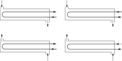
52 Heat Exchanger Design Handbook
P/NTU
t
. The Muller charts have been redrawn recently by Taborek and included in HEDH [16]. The
present form of this chart is shown in Figure 2.3e. The main difference between Figure 2.3d ande
is that the F parameter curves have been omitted in the latter, and thus the problem of having to
separately calculate the F values has been retained.
In a system with four variables, F, P, R, and NTU or NTU
t
, any chart displays just one family
of curves, such as Figure 2.3a–c, and does not give all the interrelationships directly. On the other
hand, a chart with three families of curves, as in Figure 2.3d, has one set that is redundant. To show
all the interrelationships between these four variables requires a chart with two families of curves.
This is satised by Figure 2.3e.
In the graphical presentation, ψ is plotted against P and R as a parameter as shown in Figure 2.3e. The
lines of constant R originate at ψ = 1 and terminate at ψ = 0 so that the asymptotic values of P for NTU
tend to innity. Thus the curves of constant R are similar to those for the F-P charts. In order to tie in
with the P-NTU
t
and LMTD methods, the lines of constant NTU
t
and constant F are also superimposed
on this chart. Figure 2.3e also has one limitation: It does not show directly the four parameters of interest.
Constraints due to the charts in Figure 2.3a–e are overcome by a chart, shown in Figure 2.3f, proposed
by Turton et al. [10]. The chart in Figure 2.3f extends the easy-to-read Bowman charts of Figure 2.3a to
include a second family of curves representing the variable NTU. Both the sizing and rating problems
can be solved using this form of chart, and F values can be found directly for both types of problems.
Thus to nd exchanger surface area, use P and R to evaluate F and NTU. To nd terminal temperature,
use NTU and R to evaluate P and F. Most of the charts included in this book are of the type of Figure 2.3f.
2.4 SYMMETRY PROPERTY AND FLOW REVERSIBILITY AND RELATION
BETWEEN THE THERMAL EFFECTIVENESS OF OVERALL PARALLEL
AND COUNTERFLOW HEAT EXCHANGER GEOMETRIES
2.4.1 symmetry ProPerty
The symmetry property relates the thermal behavior of a heat exchange process to that of the reverse
process, in which the directions of ow of both uids are reversed [17]. Figure 2.4 shows four dif-
ferent ow arrangements for the TEMA E
1–2
shell and tube heat exchanger that are equivalent if
complete transverse mixing of the shell uid is satised.
2.4.2 flow reversiBility
Flow reversibility establishes a relation between the thermal effectiveness of two heat exchanger
congurations that differ from each other in the inversion of either one of the two uids [18].
t
2
t
1
t
2
t
1
t
1
t
2
t
1
t
2
T
1
T
1
T
1
T
2
(a)
(b)
(c)(d)
T
1
T
2
T
2
T
2
FIGURE 2.4 Flow reversibility principle. (a) Basic E
1-2
case, (b) basic case with tube uid reversed, (c) basic
case with shell uid reversed, and (d) basic case with both shell and tube uids reversed. (Symmetry opera-
tions performed on the TEMA E
1–2
shell.) (From Pignotti, A., Trans. ASME, J. Heat Transfer, 106, 361, 1984.)

53Heat Exchanger Thermohydraulic Fundamentals
Although the inversion of both uids often does not alter the conguration, the inversion of only
one of them usually leads from one conguration to an entirely different one, as is the case in going
from a pure parallelow to a pure counterow arrangement or vice versa. Using this relation, if the
expression for the effectiveness, P, of a conguration as a function of the heat capacity rate ratio, R
(or C*), and the number of heat transfer units NTU is known, the corresponding expression for the
“inverse” conguration is immediately obtained from the simple relation [18]:
PR
PR
RP R
i
NTU
NTU
NTU
(, )
(, )
(, )
=
−
+−
1
(2.52)
where P denotes the effectiveness of a given arrangement, and P
i
, that of the same one with uid
direction reversed. The relation is valid under the assumptions of temperature independence of
the heat transfer coefcient and heat capacity rates, when one of the uids proceeds through the
exchanger in a single, mixed stream. In some cases with special symmetry, the inversion of both
uids does not alter the geometry, and therefore this property is trivially satised. Pignotti [18]
illustrates the property of ow reversibility with several examples from the available literature. An
example to clarify the meaning of Equation 2.52 is given next. Consider the well-known expression
for the effectiveness of a parallelow conguration:
PR
R
R
(, )
exp()
()
NTU
NTU
=
−− +
[
+
11
1
(2.53)
Let us derive from it the expression for the effectiveness of a pure counterow conguration,
which we denote P
c
(R, NTU). Equation 2.52 is applicable, because the counterow geometry
is obtained from parallelow by inverting the direction of ow of one of the uids, and the
condition that at least one of the uids should be mixed throughout the exchanger is satised.
After replacing R by −R in Equation 2.53 and performing the elementary algebraic operations
indicated in Equation 2.52, we obtain the expression for the effectiveness of the counterow
conguration:
PR
R
RR
c
NTU
NTU
expNTU
(, )
exp()
()
=
−− −
[]
{}
−− −
[]
{}
11
11
(2.54)
Observe also that the inversion of one uid leads from a parallelow connection to a counterow
one, and likewise, from the latter to the former; therefore, Equation 2.52 can be used to go from
parallelow to counterow and vice versa.
The transformation property of Equation 2.52 can also be expressed in terms of the variables
referred to the mixed uid. For example, if the thermal relation on the shellside or tubeside is
known in terms of P
x
, R
x
, and NTU
x
, the thermal relation for the other side P
y
, R
y
, and NTU
y
may
be obtained from the relation
PRPR
R
R
yxx
x
yx x
y
== =,,
1
NT
UN
TU
(2.55)
For example, let the tubeside values of an H
1–2
exchanger be P = 0.752, R = 0.7, and NTU = 2.5. Then
the shellside values will be P = 0.7 × 0.752, R = 1/0.7, and NTU = 0.7 × 2.5. For R = 1.0, both the
tubeside and shellside values are the same.
When the thermal effectiveness is the same for the original case and the inverted case, it is
referred to as stream symmetric. Typical examples for stream symmetric are parallelow, counter-
ow, and crossow unmixed–unmixed and mixed–mixed cases.
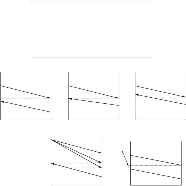
54 Heat Exchanger Design Handbook
2.5 TEMPERATURE APPROACH, TEMPERATURE
MEET, AND TEMPERATURE CROSS
The meanings of temperature approach, temperature meet, and temperature cross are as follows.
Temperature approach is the difference of the hotside and coldside uid temperature at any point
of a given exchanger. In a counterow exchanger or a multipass exchanger, (1) if the cold uid out-
let temperature t
c.o
is less than the hot uid outlet temperature t
h.o
, then this condition is referred
to as temperature approach; (2) if t
c.o
= t
h,o
, this condition is referred to as temperature meet; and
(3) if t
c.o
is greater than t
h.o
, the difference (t
c.o
− t
h.o
) is referred to as the temperature cross or tem-
perature pinch. In this case, the temperature approach (t
h.o
− t
c.o
) is negative and loses its meaning.
Temperature cross indicates a negative driving force for heat transfer between the uids. It requires
either a large area for heat transfer or the uid velocity to increase overall heat transfer coefcient.
The underlying meanings of these three cases are brought out in Table 2.3 and the same are shown
in Figure 2.5a.
The temperature cross is undesirable, particularly for shell and tube exchangers, because the
tube surface area is not utilized effectively and hence there is wastage of capital cost. If outlet
TABLE 2.3
Temperature Approach, Temperature Meet,
andTemperature Cross
Temperature Approach Temperature Meet Temperature Cross
t
h,i
→ t
h,o
t
h,i
→ t
h,o
t
h,i
→ t
h,o
t
c,o
← t
c,i
t
c,o
← t
c,i
t
c,o
← t
c,i
t
c,o
< t
h,o
t
c,o
= t
h,o
t
c,o
> t
h,o
T
1
Normal temperature distribution
(a
)(b) (c)Temperature meet
Thermodynamic
violation!
Temperature cross
t
1
t
1
t
2
t
2
T
2
T
2
t
1
T
2
T
1
t
2
T
1
(d)
a
b
x
a
–b—Temperature normal
a
΄–b—Temperature meet
a
˝–b—Temperature cross
x
—Temperature cross point
a
΄
a
˝
t
1
T
2
(e)
Temperature
approach
t
1
T
2
t
2
T
1
t
2
T
1
FIGURE 2.5 Principle of temperature approach, temperature meet, and temperature cross. (a) Normal
temperature distribution; (b) temperature meet; (c) temperature cross; (d) temperature approach, meet,
and cross superimposed; (e) temperature distribution in an E
1–2
exchanger without temperature cross;

55Heat Exchanger Thermohydraulic Fundamentals
temperatures form a temperature cross in a multiple tube pass heat exchanger, a lower than desirable
LMTD correction factor will occur. A simple way to avoid this is to use more exchanger shells in
series. Other engineers suggest that a small temperature cross may be acceptable and may provide a
less expensive design than the more complex alternatives. For a E
1–2
heat exchanger, the temperature
cross occurs around a relatively narrow range of F value about 0.78–0.82. Lower values of F may be
taken as an indication that temperature cross will occur.
The concept of the temperature cross or meet at the exchanger outlet can be utilized to determine
the number of shells in series required to meet the heat duty without having a temperature cross in
any individual shell. Temperature cross is undesirable for shell and tube heat exchanger because the
tube surface area is not utilized cost-effectively. An optimum design would mean that the tempera-
ture cross or meet point lies just at the end of the second tube pass. This phenomenon is explained
in detail by Shah [2] and is briey dealt with here with reference to an E
1–2
exchanger.
For E
1-2
two possible shell uid directions with respect to the tube uid direction are shown in
Figure 2.5b. The temperature distributions of Figure 2.5b reveal that there is a temperature cross.
In region X, the second tube pass transfers heat to the shell uid. This is contrary to the design
objective, in which ideally the heat transfer should have taken place only in one direction (from the
shell uid to the tube uid, as shown in Figure 2.5a) throughout the two passes. The reason for this
temperature cross is as follows: Although an addition of surface area (a high value of NTU
t
, or a
low value of LMTD correction factor F) is effective in raising the temperature of the tube uid and
rises in the second pass up to point X, beyond this point the temperature of the shell uid is lower
than that of the tube uid, since we have considered the shell uid mixed at a cross section and it is
cooled rapidly by the rst pass. Thus, the addition of the surface area in the second tube pass left of
point X is useless from the thermal design point of view. A “good” design avoids the temperature
cross in a shell and tube exchanger. Theoretically, the optimum design would have the temperature
cross point just at the end of the second tube pass, which will satisfy the following condition:
tt tt
t,os,o t,os,o
or=−= 0
(2.56)
This condition leads to the following formula:
P
R
=
+
1
1
(2.57)
(f)
t
1
t
1
T
2
T
1
R >1
T
1
(g)
t
1
t
1
T
2
T
2
t
2
J
1
2
t
2
R >1
T
1
T
1
T
i
T
2
T
i
t
2
t
2
FIGURE 2.5 (continued) Principle of temperature approach, temperature meet, and temperature cross.
(f) with temperature cross.

56 Heat Exchanger Design Handbook
Thus for a given R, Equation 2.57 provides the limiting (maximum) value of P. Corresponding to P
and R, the limiting (maximum) value of NTU
t
beyond which there will be a temperature cross can
be determined from its thermal relation formula. Therefore, from P, R, and NTU, F can be calcu-
lated. This F value is known as the F
min
value beyond which there will be a temperature cross. This
is illustrated for an E
1–2
exchanger here. For a known value of R, determine the limiting value of P
from Equation 2.57 and NTU from the following equation:
NTUln
E
12
1
1
211
211
205
205
205
−
=
+
−+−+
−+++
()
()
()
.
.
.
R
PR R
PR R
(2.58)
For known values of P, R, and NTU, determine F from Equation 2.36.
2.5.1 temPerature Cross for other tema shells
Temperature cross for other TEMA shells such as G
1–2
, H
1–2
, and J
1–2
can be evaluated from Equation
2.57 [19]. The F
min
curves for G
1–2
, H
1–2
, and J
1–2
cases are given in the next section.
2.6 THERMAL RELATION FORMULAS FOR VARIOUS FLOW
ARRANGEMENTS AND PASS ARRANGEMENTS
The heat exchanger effectiveness is dened as the ratio of the overall temperature drop of the weaker
stream to the maximum possible temperature difference between the uid inlet temperatures. The
following assumptions are commonly made in deriving thermal effectiveness:
1. The overall heat transfer coefcient is constant throughout the exchanger.
2. Each pass has the same heat transfer area; that is, unsymmetrical pass arrangements are
not considered.
3. There is no phase change.
4. The specic heat of each uid is constant and independent of temperature.
5. The ow rates of both streams are steady.
6. The ow of both uids is evenly distributed over both the local and the total transfer area.
7. Heat losses from the system are negligible.
In this section, thermal relation formulas for (1) various ow arrangements—parallelow, coun-
terow, and crossow—(2) various types of heat exchangers—compact and shell and tube—and (3)
multipass arrangements or multiple units of both compact and shell and tube heat exchangers are
presented. Most of the formulas are tabulated and the thermal effectiveness charts are given. Mostly
counterow arrangements are considered. For shell and tube exchangers, formulas are given for both
parallelow and counterow, but thermal effectiveness charts are given only for counterow arrange-
ments referred to tubeside (similar to TEMA Standards [15]). For stream symmetric cases, thermal
effectiveness relations referred to the shellside can be derived from the “ow reversibility” principle.
From counterow thermal effectiveness relations, thermal effectiveness relations for parallelow
arrangements can be easily derived (for stream symmetric cases only) from the “ow reversibility”
principle. Customarily, the ε-NTU method is employed for compact heat exchangers. In this method,
the capacity ratio C* is always ≤1. Hence, thermal effectiveness charts are given in terms of ε–C*–
NTU, and wherever possible, the thermal effectiveness charts are also given in terms of P–R–F–NTU,
instead of ε–C*–NTU.
57Heat Exchanger Thermohydraulic Fundamentals
2.6.1 Parallelflow
For a given set of values of C* or R, and NTU, (1) the thermal effectiveness is much lower for paral-
lelow than for counterow arrangement, except in the limiting case C* = R = 0, where it is the same
for both cases and approaches unity as NTU increases to innity, and (2) at a given value of NTU, the
effectiveness increases with decreasing capacity ratio, C* or R. The formula for thermal effectiveness
is given by Equation T1 in Table 2.4, and the thermal effectiveness chart is given in Figure 2.6.
2.6.2 Counterflow
Among the various ow arrangements, counterow has the highest thermal effectiveness. For coun-
terow exchangers, at a given value of NTU, the effectiveness increases with decreasing capacity
ratio, C* or R. The formula for thermal effectiveness is given by Equation T2, and the thermal
effectiveness chart is given in Figure 2.7.
2.6.3 Crossflow arrangement
2.6.3.1 Unmixed–Unmixed Crossflow
This is an industrially important arrangement representing the case of a large number of unmixed
channels in both sides. The original solution was due to Nusselt [20] and was later reformulated
into a more manageable equation by Mason [21]. Mason’s formula is given by Equation T3, and this
equation can be used for P–NTU–R relation. Baclic [22] presents Nusselt’s equation in terms of a
modied Bessel function of the rst kind as given in Equation T4; Eckert [23] provides a simplied
formula without involving Bessel function as given by Equation T5, and this equation predicts ε
within ±1% of ε from Equation T4 for 1 < NTU < 7; Equations T4 and T5 can be used for formulas
involving C* ≤ 1 only. The thermal effectiveness chart as per Equation T3 is given in Figure 2.8 and
as per Equation T4 is given in Figure 2.9.
2.6.3.2 Unmixed–Mixed Crossflow
In this arrangement, one uid is mixed and the other is unmixed. A typical example is a bare
tube compact heat exchanger in which the uid outside the tube is mixed, whereas the tubeside
uid is unmixed. There are two possible cases: (1) weaker uid (C
min
) is mixed and (2) stronger
uid (C
max
) is mixed. Formulas for thermal effectiveness for the weaker uid mixed are given by
Equation T6 and for the stronger uid mixed by Equation T7. The thermal effectiveness charts
are given in Figure 2.10 for the weaker uid mixed and Figure 2.11 for the stronger uid mixed.
For R = 1 or C* = 1, the thermal effectiveness is the same for both cases.
2.6.3.3 Mixed–Mixed Crossflow
This case has no industrial application and is shown here only as an extreme of the crossow
arrangement. The solution is identical to the TEMA J shell with innite tubeside passes. The for-
mula for thermal effectiveness is given by Equation T8.
2.6.3.4 Single or Multiple Rows in Crossflow
Many process heat exchangers provide a crossow arrangement between the hot (or cold) process
uid that ows through the tubes and the external coolant (or hot air such as supercharged engine
intake air), usually air. Because this ow arrangement is not strictly countercurrent, the MTD must be
corrected by applying a correction factor, F. The factor F depends on the terminal temperatures, the
number of tube rows per pass, and the number of passes. The basic unmixed–unmixed case shown in
Figure 2.12 assumes a large number of ow channels in both streams. For a single tubeside pass with
one or more tube rows, the thermal effectiveness formula is different from that of the basic unmixed–
unmixed case. Thermal relations for single-pass tube rows arrangements are discussed next.
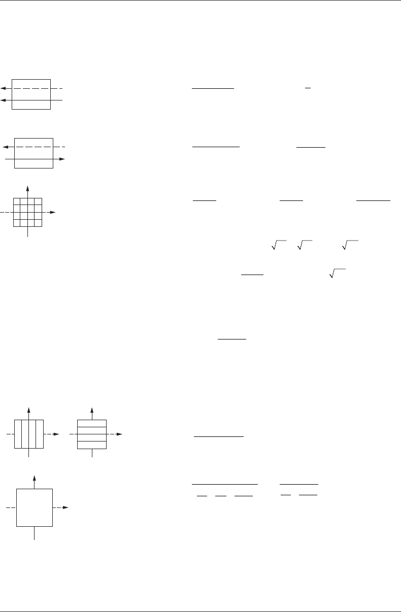
58 Heat Exchanger Design Handbook
TABLE 2.4
Thermal Effectiveness Relations for Basic Cases
Flow Arrangement
Equation
No./
Reference General Formula Value for R = 1 and Special Cases
1
2
Parallelow; stream symmetric
T1
P
e
R
R
=
−
+
−+
1
1
NTU(1)
Pe R
eR
PR
=− =
=− =
==
−
1
2
1
0
50 1
[]
%
max
(2NTU)
NTO
for1
1for
for
−
1
2
Counterow; stream symmetric
T2
P
e
Re
R
R
=
−
−
−
−
1
1
NTU(
1)
NTU(
1)
−
−
PR
eR
=
+
=
=− =
−
NTU
NTU
for
for
NTU
1
1
10
1
2
T3 [21]
P
R
e
m
e
m
m
m
k
R
m
m
k
=−
−
−−
=
∑∑
1
11
0
NTU
NT
UR
NTU
!
NTU
=0
NTU
!
()
=
=
∞
∑
k
R
0
1Forthisequation holds.,
T4 [22]
ε= −+
−
−
−
12
1
01
eICCIC
C
C
CI
C[(
()(*)
*
*
*(
1+ *)NTU]
n/2
n
NTU* *2NTU
2 NNTU
n
C*)
=
∞
∑
2
Crossow; both the uids unmixed;
stream symmetric
For C* = 1.
ε= −+
−
1
01
eI I
2NTU
2NTU 2NTU()()
T5 [23]
ε=
−−
−
11
022
078
exp
*
[exp(
*)
]
.
.
NTU
NTU
C
C
Crossow; one uid mixed
and the other uid unmixed (1)
weaker (C
min
) uid mixed;
(2)stronger (C
max
) uid mixed
T6
Weaker (C
min
) uid mixed
Pe
1
1
1=−
−−
−
()
NTU
e
P
1
= [1 − exp(−K/R)]
K = 1 − exp(−RNTU)
1
1
22
T7 Stronger (C
max
) uid mixed
P
KR
R
1
1
=
−−[exp( )]
K = 1 − exp(−NTU)
Pe
1
1
1
=−
−−
−
()e
NTU
1
2
Crossow; mixed–mixed ow;
stream symmetric same as J
1–∞
P
K
R
K
P
K
=
+−
=
−
1
11
1
21
12
1
NTU
NTU
K
1
= 1 − e
(–NTU)
K
2
= 1 − e
(–RNTU)
T8
Note: P
2
can be found using Equation 2.55;
I
0
, I
1
and I
n
are modied Bessel functions of the rst kind.
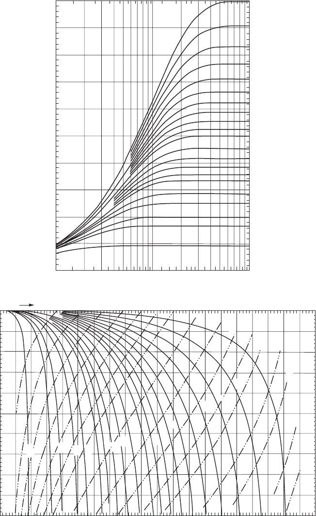
59Heat Exchanger Thermohydraulic Fundamentals
1.0
0.9
0.8
0.7
0.6
0.5
0.4
P, Thermal effectiveness
0.3
0.2
0.1
0.0
0.1 0.2 0.3 0.4
(a) NTU
0.5 1.0 2.0
2.0
1.8
1.6
1.4
1.2
0.1
0.2
0.3
0.4
0.5
0.6
0.8
0.9
1.0
R = 0
2.5
3.0
3.0
4.0
4.0
5.0
5.0
10.0
10.0
0.7
3.0
1.0
NTU
0.9
0.8
0.7
0.6
10.0
5.0
4.0
2.5
2.0
1.8
1.6
1.4
1.2
1.0
0.9
0.8
0.7
0.6
0.5
0.4
0.3
0.2
0.1
0.5
0.1 0.2
0.2
0.3
0.3
0.4
0.4
0.5
0.5
P, ermal effectiveness(b)
F, Correction factor
0.6
0.6
0.7
0.7
0.8
0.8
0.9
1.0
1.0
1.25
1.50
1.75
2.0
2.5
3.0
4.0
5.0
0.9
FIGURE 2.6 (a) Thermal effectiveness chart—parallelow; stream symmetric, R–P–NTU chart (as per
Equation T1, Table 2.4); (b) parallelow; stream symmetric, F–R–P–NTU chart; F as a function of P for
constant R (solid lines) and constant NTU (dashed lines) (Equation T1, Table 2.4).
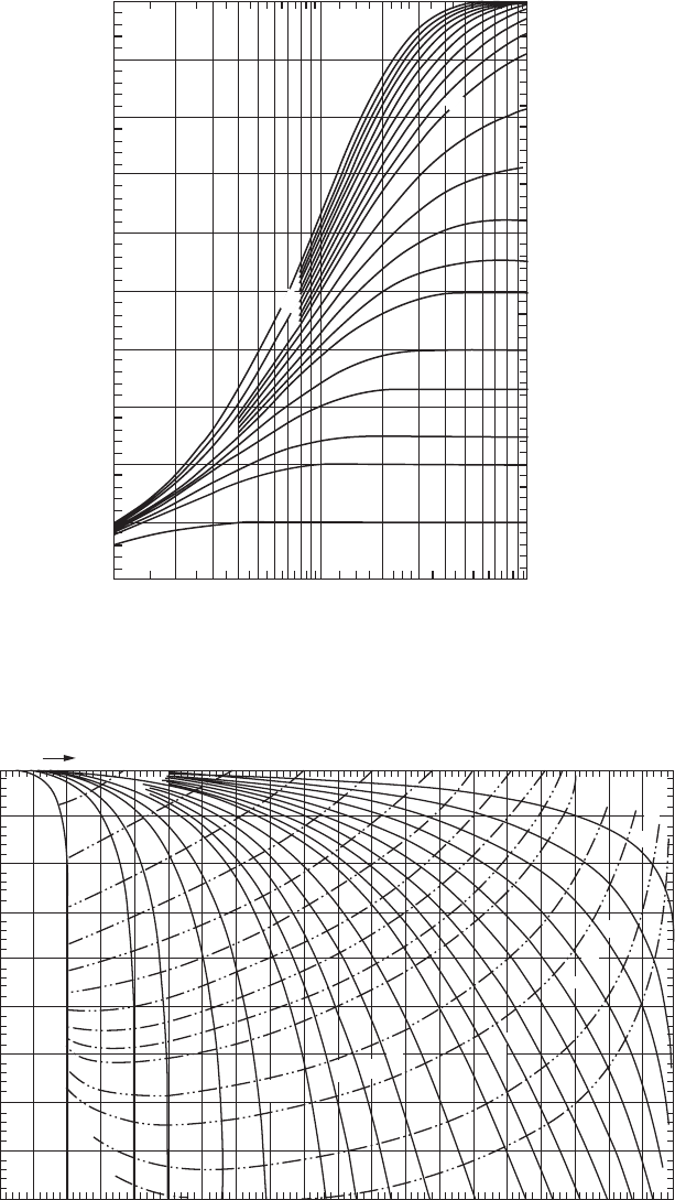
60 Heat Exchanger Design Handbook
1.0
0.9
0.8
0.7
0.6
P
1
, ermal effectiveness
0.5
0.4
0.3
0.2
0.1
0.0
0.1 0.2 0.3 0.4 0.5
NTU
1234
51
0
10.0
5.0
4.0
3.0
2.5
2.0
1.8
1.6
1.4
1.2
R = 0
1.0
0.5
FIGURE 2.7 Thermal effectiveness chart—counterow; stream symmetric, R–P–NTU chart (as per
Equation T2, Table 2.4).
1.00
0.2
0.4
0.6
0.8
1.0
1.2
1.4
2.5
3.0
0.2
0.3
0.4
0.5
0.6
0.7
0.8
0.9
1.0
1.2
1.4
1.6
1.8
2.0
3.0
4.0
5.0
10.0
5.0
1.6
1.8
2.0
0.95
0.90
0.85
0.80
0.75
0.70
F, Correction factor
P, ermal eectiveness
0.65
0.60
0.55
0.1 0.2 0.3 0.4 0.5 0.6 0.7 0.8 0.9
1.0
2.5
0.1
4.0
NTU
FIGURE 2.8 Thermal effectiveness chart—crossow; both the uids unmixed; stream symmetric; F–R–P–
NTU chart; F as a function of P for constant R (solid lines) and constant NTU (dashed lines) (as per Equation T3,
Table 2.4).

61Heat Exchanger Thermohydraulic Fundamentals
2.6.3.4.1 Single Tubeside Pass, N Rows per Pass, Both Fluids Unmixed
A common header at one end of the tubes distributes the tubeside uid into a single pass hav-
ing N rows in parallel. A similar header at the other end collects tubeside uid. For given ter-
minal temperatures, F increases with the number of rows per pass and the number of passes
being increased and is more sensitive to the latter. Taborek [24], Pignotti and Cordero [25], and
Pignotti [26] present values of F for a variety of crossow congurations, applicable to air-
cooled heat exchangers.
Schedwill’s formula for the thermal effectiveness of N rows is given by [27]
P
R
Ne
i
j
Ke
k
j
i
jijN
k
k
j
i
N
=−
+
=
−−
==
−
∑∑
1
1
1
00
1
NKR
NTU/
(NKR)
()
!
11
1
∑
−
(2.59)
1.0
0.9
0.8
0.7
0.6
0.5
0.5 1.0
NTU
2.03.0
3.0
2.5
2.0
1.8
1.6
1.4
1.2
1.0
R =
0
0.1
0.2
0.3
0.4
0.5
0.6
0.7
0.8
0.9
4.0
4.0
5.0
5.0
10.0
10.
0
0.4
0.4
0.3
0.3
P
1
, ermal effectiveness
0.2
0.2
0.1
0.1
0.0
FIGURE 2.9 Thermal effectiveness chart—crossow; both the uids unmixed; stream symmetric; R–P–
NTU chart (as per Equation T4, Table 2.4).
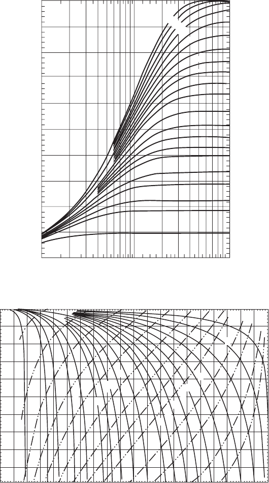
62 Heat Exchanger Design Handbook
1.0
0.9
0.8
0.7
0.6
0.5
0.5 1.0 2.0 3.0
R = 0
0.1
0.2
0.3
0.4
0.5
0.6
0.7
0.8
0.9
4.0 5.0
10.0
0.4
0.4
0.3
0.3
P
1
, Th
ermal effectiveness
0.2
0.2
0.1
0.1
0.0
NTU
(a)
1.75
1.25
1.5
0.1
0.2
0.3
0.4
0.5
0.6
0.7
0.8
0.9
1.0
1.2
1.4
1.6
1.8
2.0
3.0
4.0
5.0
10.0
2.5
1.0
0.8
0.6
0.4
0.2
1.0
0.9
0.8
0.7
0.6
0.5
0.1
0.2
0.3
NTU
0.4
0.5
0.6
0.7
0.8
0.9
1.0
2.0
2.5
3.0
4.0
5.0
P
1
, Thermal effectiveness
F, Correction factor
(b)
FIGURE 2.10 (a) Thermal effectiveness chart—crossow: unmixed–mixed—the weaker (C
min
) uid mixed,
R–P–NTU chart (as per Equation T6, Table 2.4); (b) F–R–P–NTU chart; F as a function of P for constant R
(solid lines) and constant NTU (dashed lines) (as per Equation T6, Table 2.4).

63Heat Exchanger Thermohydraulic Fundamentals
1.0
0.1
0.2
0.3
0.4
0.5
0.6
0.7
0.8
0.9
R = 0
1.2
1.4
1.6
1.8
2.0
2.5
3.0
4.0
5.0
10.
0
10.0
5.0
4.0
3.0
2.0
1.0
0.5
0.4
0.3
0.2
0.1
0.0
0.1
0.2
0.3
0.4
P
1
, Thermal effectiveness
0.5
0.6
0.7
0.8
0.9
1.0
(a) NTU
0.6
1.0
0.2
0.1
0.2
0.3
0.4
0.5
0.6
0.7
0.8
0.9
1.0
F-Correction factor
(b)
2.5
3.0
2.0
1.8
1.6
1.4
1.2
1.0
0.9
0.8
0.7
0.5
5.0
4.0
3.0
2.5
1.75
2.0
0.4
0.3
0.2
0.1
4.0
P
1
, Thermal effectiveness
0.4
0.6
0.8
1.0
1.25
1.50
0.9
0.8
0.7
0.6
0.5
5.0
10.0
NTU
FIGURE 2.11 (a) Thermal effectiveness chart—crossow: unmixed–mixed—the stronger (C
max
) uid mixed,
ε-C*-NTU chart (as per Equation T7, Table 2.4); (b) Thermal effectiveness chart: F–R–P–NTU chart; F as a
function of P for constant R (solid lines) and constant NTU (dashed lines) (as per Equation T7, Table 2.4).

64 Heat Exchanger Design Handbook
where
i
j
i
ijj
=
−
!
()!!
(2.60)
that is, the number of combinations of i and j taken j at a time, and
K
N
=− −
1exp
NTU
(2.61)
By substituting N = 1, 2, 3, … in Equations 2.59 and 2.61, equations for thermal relations are
obtained for the specic arrangements by Nicole [28], and this is given in Table 2.5 (Equations T9
through T12) for one row, two rows, three rows, and four rows. For a larger number of tube rows
(for all practical purposes, when N exceeds 5), the solution approaches that of unmixed–unmixed
crossow arrangement. Values of F for N = 1, 2, 3, 4 are shown in Figures 2.13 through 2.16 and are
always less than the basic case of unmixed–unmixed crossow (Figure 2.8).
2.6.3.4.2 Multipass Tube Rows Cross-CounterflowArrangements,BothFluidsUnmixed,
andMultiple Tube Rows in MultipassTube Rows,Cross-Counterflow
Arrangements
This would apply to a manifold-type air cooler in which the tubes in one row are connected to the
next by U-bends. The solutions are based on Ref. [28]. Solutions for the 2 rows-2 pass and 3 rows-3
pass cases are based on Stevens et al. [29]. The general formula for thermal effectiveness referred to
the air side (n side) is given by [28]
P
R
1
1
1
1
=−
ζ
(2.62)
The expressions for ζ for various cases are as follows:
1. Two-tube rows, two passes, as shown in Figure 2.17a [29]
ζ= +−
KK
e
KR
2
1
2
2
(2.63a)
K =− −
1exp
NTU
2
(2.63b)
2
1
FIGURE 2.12 Unmixed–unmixed crossow arrangement.
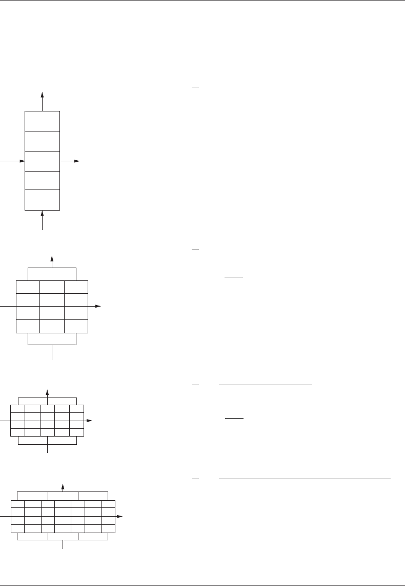
65Heat Exchanger Thermohydraulic Fundamentals
TABLE 2.5
Thermal Effectiveness Relations for Tube Rows with Single Pass Arrangement
Flow Arrangement
Equation
No./
Reference
General Formula, Ref. [28]. Note: These Formulas
Are Valid for R = 1
One-tube row
1
2
T9 [28]
P
R
e
K
KR
1
1
1
1
=−
=− −
−
()
exp( NTU)
Two-tube rows
1
2
T10 [28]
P
R
eR
K
K
KR
1
22
1
11
1
2
=− +
=− −
−
()
exp
NTU
Three-tube rows
1
2
T11 [28]
P
R
e
RK KRK
K
KR
1
3
22
4
1
1
1
13 32
1
=−
+−+
=− −
−
()()
exp
/
N
TTU
3
Four-tube rows
1
2
T12 [28]
P
R
e
RK KK RK KRK
KR
1
4
2224 36
1
1
1
1644283
=−
+−++ −+
−
[( )()( )/
=− −
K 1exp( NTU/4)
Note: To nd P
2
, use Equation 2.55.
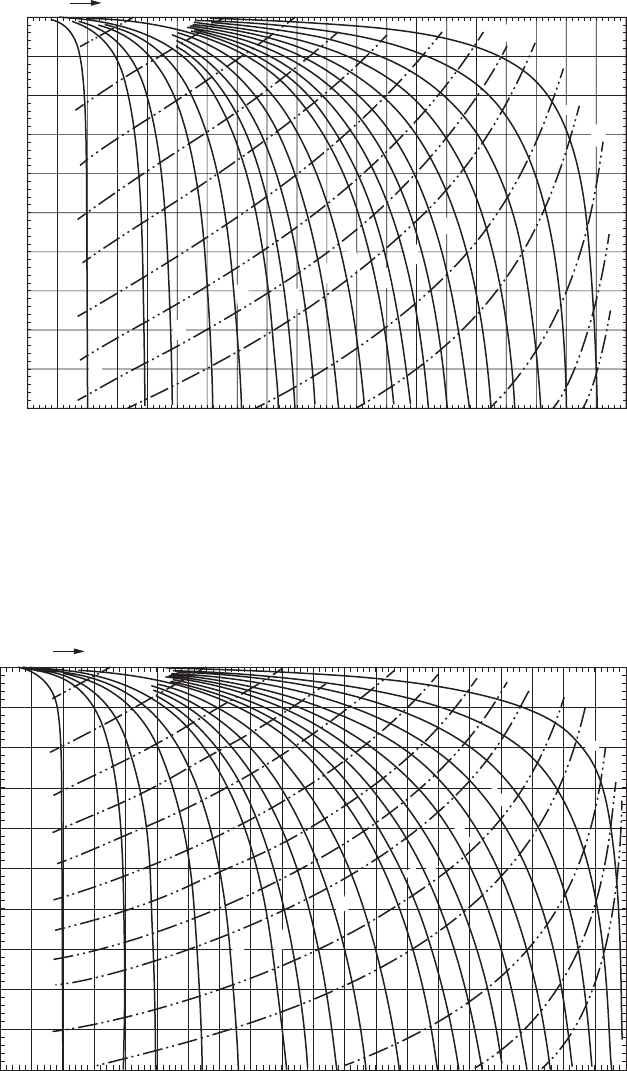
66 Heat Exchanger Design Handbook
1.
0
0.90.80.70.6
1.50
1.25
1.0
0.8
0.6
0.4
0.2
1.0
0.9
0.8
10.0
5.0
4.0
3.0
2.5
2.0
1.8
1.6
1.4
1.2
1.0
0.9
0.8
0.7
0.6
0.5
0.4
0.3
0.2
0.1
1.75
2.0
2.5
3.0
4.0
5.0
6.0
0.7
0.6
0.5
0.50.40.30.20.1
NTU
P
1
, Thermal effectiveness
FIGURE 2.14 Thermal effectiveness chart—two-tube rows; F as a function of P for constant R (solid lines)
and constant NTU (dashed lines) (as per Equation T10, Table 2.5).
1.0
0.9
0.8
0.7
0.6
1.50
1.25
1.0
0.8
0.6
0.4
0.2
1.0
0.9
0.8
F, Correction factor
10.0
5.0
4.0
3.0
2.5
2.0
1.8
1.6
1.4
1.2
1.0
0.9
0.8
0.7
0.6
0.5
0.4
0.3
0.2
0.1
1.75
2.0
2.5
4.0
5.0
6.0
0.7
0.6
0.5
0.5
0.4
0.3
0.2
0.1
3.0
NTU
P
1
, Thermal effectiveness
FIGURE 2.13 Thermal effectiveness chart—one-tube row; F as a function of P for constant R (solid lines)
and constant NTU (dashed lines) (as per Equation T9, Table 2.5).
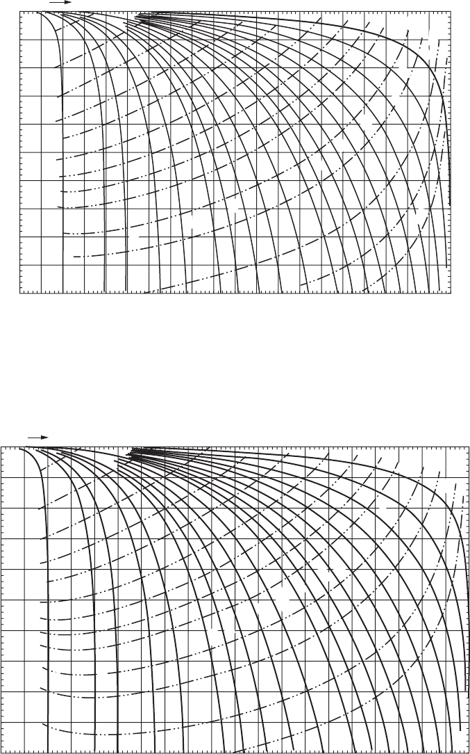
67Heat Exchanger Thermohydraulic Fundamentals
1.0
0.9
0.8
0.7
0.6
1.50
1.25
1.0
0.8
0.6
0.4
0.2
1.0
0.9
0.8
F, Correction factor
10.0
5.0
4.0
3.0
2.5
2.0
1.8
1.6
1.4
1.2
1.0
0.9
0.8
0.7
0.6
0.5
0.4
0.3
0.2
0.1
1.75
2.0
2.5
3.0
4.0
5.0
6.0
0.7
0.6
0.5
0.5
0.4
0.3
0.2
0.1
NTU
P
1
, Thermal effectiveness
FIGURE 2.15 Thermal effectiveness chart—three-tube rows; F as a function of P for constant R (solid lines)
and constant NTU (dashed lines) (as per Equation T11, Table 2.5).
1.0
0.9
0.8
0.7
0.6
1.0
0.9
0.8
10.0
5.0
4.0
3.0
2.5
2.0
1.80
1.60
1.40
1.20
1.0
0.9
0.8
0.7
0.6
0.5
0.4
0.3
0.2
0.1
2.5
3.0
4.0
5.0
0.7
F, Correction factor
0.6
0.5
0.5
P
1
, Thermal effectiveness
0.4
0.3
0.2
0.1
2.0
1.75
1.50
1.25
1.0
0.8
0.6
0.4
0.2
NTU
FIGURE 2.16 Thermal effectiveness chart—four-tube rows; F as a function of P for constant R (solid lines)
and constant NTU (dashed lines) (as per Equation T12, Table 2.5).
