BY ORDER OF THE COMMANDER
LITTLE ROCK AIR FORCE BASE
LITTLE ROCK AIR FORCE BASE
INSTRUCTION 13-250
29 APRIL 2010
Incorporating Change 1, 27 February 2014
Corrective Actions applied on 11 March 2014
Space, Missile, Command, and Control
AIRFIELD OPERATIONS AND LOCAL
FLYING PROCEDURES
COMPLIANCE WITH THIS PUBLICATION IS MANDATORY
ACCESSIBILITY:
Publications and forms are available on the e-Publishing website at
www.e-publishing.af.mil for downloading or ordering.
RELEASABILITY:
There are no releasability restrictions on this publication.
OPR: 19 OSS/OSA
Supersedes: LITTLEROCKAFBI13-250,
15 Oct 2007
Certified by: 19 OG/CC
(Colonel David A. Kasberg)
Pages: 65
This instruction implements AFPD 13-2, Air Traffic Control, Airspace, Airfield, and Range
Management, 13 series AFIs, and directs procedures to be used for airfield operations activities
at Little Rock AFB. It defines requirements and responsibilities of support agencies for services
required and provided. The procedures and instructions are directive for all assigned base and
partner units and aircrews, but are not intended to supplement good judgment in the interest of
flight safety. The Airfield Operations Board (AOB) has approved this instruction. Deviations to
this instruction are authorized only when directed by Air Traffic Control (ATC), Airfield
Management (AM), or in emergency situations where adherence would jeopardize safe aircraft
operations. This instruction combines various directives, which affect the entire ATC system at
Little Rock AFB, into one document common to all users and service agencies.
Recommendations for improvements to this instruction are encouraged. Changes will be
submitted to the Little Rock AFB Airfield Operations Board (AOB) through the 19th Operations
Support Squadron Airfield Operations Flight (19 OSS/OSA) using the exact wording desired for
approval on AF Form 847, Recommendation for Change of Publication. Prior to submission,
changes must be coordinated by the submitting organizations with all affected agencies. 19
OSS/OSA, Airfield Operations Flight Commander, or representative will incorporate all changes
approved by the board. This instruction will be reviewed by the AOB annually. The use of the
name or mark of any specific manufacturer, commercial product, commodity, or service in this
publication does not imply endorsement by the Air Force.

2 LITTLEROCKAFBI13-250 29 APRIL 2010
“Ensure that all records created as a result of processes prescribed in this publication are
maintained in accordance with Air Force Manual (AFMAN) 33-363, Management of Records,
and disposed of in accordance with Air Force Records Information Management System
(AFRIMS) Records Disposition Schedule (RDS) located at http://ttps/www.my.af.mil/gcss-
af61a/afrims/afrims/.”
SUMMARY OF CORRECTIVE ACTIONS
Missing paragraphs 4.8.1 and 4.8.1.1 were added.
SUMMARY OF CHANGES
This interim change revises LRAFBI 13-250 by (1) changing the “Quiet Hours” options, (2)
updating pattern altitudes, (3) removing procedural references to the Supervisor of Flying (SOF),
(4) updating coordination requirements for airfield lighting checks, engine tests, and airfield
closures, (5) adjusting drop zone/landing zone procedures, (6) updating Night Vision Goggle
operations, (7) updating facility evacuation locations, (8) modifying flight plan filing procedures,
and (9) modifying local aircraft priorities. A margin bar (|) indicates newly revised material.
Chapter 1—GENERAL INFORMATION 7
1.1. Scope. ..................................................................................................................... 7
1.2. Policy. .................................................................................................................... 7
1.3. Quiet Hours for Special Events on and Around the Flight Line. ........................... 7
1.4. Airfield Coordination Requirements. ..................................................................... 8
1.5. Airfield Construction. ............................................................................................ 9
Chapter 2—AIRFIELD FACILITIES INFORMATION 10
2.1. Airfield Information. .............................................................................................. 10
2.2. Runway and Assault Zone. .................................................................................... 10
2.3. Taxiways. ............................................................................................................... 10
2.4. Runway Selection Procedures. ............................................................................... 10
2.5. Airfield Lighting Systems. ..................................................................................... 10
2.6. Permanently Closed/Unusable Portions of Airfield. .............................................. 11
2.7. Aircraft Arresting Systems. ................................................................................... 11
2.8. Parking Plan/Restrictions. ...................................................................................... 11
2.9. Air Traffic Control and Airfield Management Operations Facilities. .................... 12
2.10. Local Frequencies. ................................................................................................. 12
Table 2.1. Local Frequencies. ................................................................................................. 13
2.11. Navigational Aids (NAVAIDS), Preventative Maintenance Inspection (PMI), and
Generator Power. ................................................................................................... 13
LITTLEROCKAFBI13-250 29 APRIL 2010 3
Table 2.2. NAVAIDS Location, Frequency, & IDENT. ........................................................ 14
2.12. Transient Alert. ...................................................................................................... 15
2.13. Automated Terminal Information Service (ATIS) Procedures. ............................. 15
2.14. Aircraft Special Operations Areas. ........................................................................ 15
2.15. Aircraft Tow Procedures. ....................................................................................... 15
2.16. Aircraft Taxiing Requirements/Routes. ................................................................. 16
2.17. Airfield Maintenance (Airfield Sweeper, Airfield Lighting Procedures, Airfield
Mowing. ................................................................................................................. 16
Figure 2.1. Weekly Area Sweeping Schedule and Diagram. ................................................... 17
2.18. Runway Surface Condition (RSC) and Runway Condition Reading (RCR)
Values. ................................................................................................................... 19
2.19. Runway Inspections/Checks Procedures and Requirements. ................................ 19
2.20. Engine Test/Run-Up Procedures. ........................................................................... 20
2.21. Noise Abatement Procedures. ................................................................................ 21
2.22. Noise Complaints. .................................................................................................. 21
2.23. Protecting Precision Approach Critical Areas. ...................................................... 21
Figure 2.2. ILS/Localizer Critical Area. ................................................................................... 21
Figure 2.3. RWY 25 ILS/Glideslope and POFZ Critical Areas. .............................................. 22
2.24. Airfield Restricted Areas. ...................................................................................... 23
2.25. Runway Suspension Procedures. ........................................................................... 23
2.26. Airfield Closure Procedures. .................................................................................. 23
2.27. Airfield Opening Procedures. ................................................................................ 23
2.28. Radio and Visual Blind Spots. ............................................................................... 24
2.29. Aircraft Rescue Fire Fighting (ARFF). .................................................................. 24
Chapter 3—LOCAL FLYING AREAS 25
3.1. General Description of Local Terrain and Obstructions. ....................................... 25
3.2. Local Flying Area. ................................................................................................. 25
3.3. Designation of Airspace. ........................................................................................ 25
3.4. Fixed Wing Functional Check Flight (FCF) Area. ................................................ 25
3.5. Restricted Areas. .................................................................................................... 25
3.6. VFR Local Training Areas. .................................................................................... 26
3.7. Local Drop Zones. ................................................................................................. 26
3.8. Practice Approaches by Transient Aircraft. ........................................................... 27
4 LITTLEROCKAFBI13-250 29 APRIL 2010
Chapter 4—VFR PROCEDURES 28
4.1. VFR Weather Minimums. ...................................................................................... 28
4.2. VFR Traffic Patterns. ............................................................................................. 28
4.3. Assault Zone (AZ) Operations. .............................................................................. 30
4.4. Helicopter Operations. ........................................................................................... 31
4.5. Special Procedures. ................................................................................................ 31
4.6. Low Altitude Closed Traffic and Circling Approach Procedures. ......................... 33
4.7. Reduced Same Runway Separation Procedures. .................................................... 34
4.8. Line up and Wait Procedures. ................................................................................ 35
4.9. Intersection Departures. ......................................................................................... 35
4.10. Night Vision Goggle (NVG) Operations. .............................................................. 36
Chapter 5—IFR PROCEDURES 37
5.1. Air traffic control service at Little Rock AFB. ...................................................... 37
5.2. IFR Control. ........................................................................................................... 37
5.3. Radar Traffic Patterns. ........................................................................................... 37
5.4. Radar Vector to Initial Procedures. ........................................................................ 37
5.5. Local Departure Procedures. .................................................................................. 37
5.6. Availability/Restrictions for Surveillance (ASR) Approaches and Precision
Approach Radar (PAR) Approaches/Monitoring. ................................................. 38
Chapter 6—EMERGENCY PROCEDURES 39
6.1. General. .................................................................................................................. 39
6.2. Types of Declared Emergencies. ........................................................................... 39
6.3. Operation of Primary Crash Alarm System (PCAS) and Secondary Crash Net
(SCN). .................................................................................................................... 39
6.4. On/Off-Base Aircraft Mishaps or Emergencies. .................................................... 39
6.5. External Stores Jettison Areas. .............................................................................. 40
6.6. Fuel Dumping Procedures. ..................................................................................... 40
6.7. Emergency Arresting/Barrier Gear Procedures. .................................................... 40
6.8. Hot Brake Areas and Procedures. .......................................................................... 40
6.9. Abandonment/Bailout of Aircraft. ......................................................................... 40
6.10. Personnel/Crash Locator Beacon Signal/Emergency Locator Transmitters (ELT)
Response Procedures. ............................................................................................ 40
6.11. Combat Aircraft Arm/De-arm/Hot Gun/Hung Ordnance/Hot Flares/Chaff
Bundles .................................................................................................................. 40
LITTLEROCKAFBI13-250 29 APRIL 2010 5
6.12. Hydrazine Parking Area. ........................................................................................ 41
6.13. Unlawful Seizure of Aircraft Procedures. .............................................................. 41
6.14. Aircraft Engine Start and Movement (Anti-hijacking). ......................................... 41
6.15. Wind Limitations on the Control Tower. ............................................................... 41
6.16. Evacuation of ATC and AM Operations Facilities. ............................................... 41
6.17. Alternate Facilities. ................................................................................................ 41
6.18. Combat Arms and Explosive Ordnance Disposal (EOD) Area ............................. 42
6.19. Emergency Airfield Checks. .................................................................................. 42
Chapter 7—AIRFIELD VEHICLE (CMA)/PEDESTRIAN OPERATIONS 43
7.1. Responsibilities ..................................................................................................... 43
7.2. Controlled Movement Area (CMA. ....................................................................... 43
7.3. Vehicle Control Area (VCA. ................................................................................. 43
7.4. Airfield Driving Requirements. ............................................................................. 43
7.5. Privately Owned Vehicles (POV) and Government Leased Vehicles (GLV. ....... 43
7.6. Vehicle Traffic Procedures. ................................................................................... 43
7.7. Vehicular Call Signs. ............................................................................................. 43
7.8. Airfield Driving Violations and Penalties. ............................................................. 43
7.9. Emergency Vehicle Operations. ............................................................................ 43
7.10. Airfield Construction/Work Crew/Maintenance Restrictions ................................ 44
Chapter 8—FLIGHT PLANNING PROCEDURES 45
8.1. Flight Plans. ........................................................................................................... 45
8.2. Emailing or Faxing Flight Plans. ........................................................................... 45
8.3. Responsibilities. ..................................................................................................... 45
Chapter 9—MISCELLANEOUS PROCEDURES 46
9.1. Airfield Operations Board (AOB. .......................................................................... 46
Table 9.1. AOB Membership .................................................................................................. 46
9.2. Notice to Airmen (NOTAM) System Procedures. ................................................. 47
9.3. Flight Information Publication (FLIP) Accounts and Procedures for Requesting
Changes. ................................................................................................................. 48
9.4. Waivers to Airfield/Airspace Criteria. ................................................................... 48
9.5. Prior Permission Requested (PPR) Procedures. ..................................................... 48
9.6. Arriving Air Evac Notification and Response Procedures. ................................... 48
9.7. Unscheduled Aircraft Arrivals. .............................................................................. 48
6 LITTLEROCKAFBI13-250 29 APRIL 2010
9.8. Distinguished Visitor (DV) Notification Procedures. ............................................ 48
9.9. Dangerous/Hazardous Cargo. ................................................................................ 49
9.10. Wear of Hats. ......................................................................................................... 49
9.11. Local Aircraft Priorities. ........................................................................................ 49
9.12. Lost Communication Instructions. ......................................................................... 50
9.13. Standard Climb-out Instructions. ........................................................................... 51
9.14. Opposite Direction Take-offs and Landings. ......................................................... 51
9.15. Breakout/Go Around/Missed Approach Procedures. ............................................. 51
9.16. Flight Line Smoking Policy ................................................................................... 51
9.17. Civilian Aircraft Operations. ................................................................................. 51
9.18. Civil Use of Military NAVAIDS. .......................................................................... 52
9.19. Aero Club Operations. ........................................................................................... 52
9.20. Weather Dissemination and Coordination Procedures – Hazardous/Severe
Weather Notification Procedures and Lightning Response ................................... 52
9.21. Airfield Snow Removal Procedures. ...................................................................... 53
9.22. Bird/Wildlife Control – BASH. ............................................................................. 53
9.23. Bird Hazard Notification System. .......................................................................... 53
9.24. DELETED. ............................................................................................................ 53
9.25. Taking of Photographs on the Airfield. ................................................................. 53
9.26. Joint Readiness Training Center (JRTC) Ground Operations. .............................. 53
9.27. Mid-Air Collision Avoidance Program (MACA. .................................................. 53
9.28. Quarterly Joint Airfield Inspection. ....................................................................... 54
9.29. Annual Airfield Certification/Safety Inspection. ................................................... 54
9.30. Hearing Protection. ................................................................................................ 54
9.31. DELETED. ............................................................................................................ 55
9.32. Adopted IMTs/Forms. ........................................................................................... 55
Attachment 1—GLOSSARY OF REFERENCES AND SUPPORTING INFORMATION 56
Attachment 2—FIXED WING TRAFFIC PATTERNS DIAGRAM 60
Attachment 3—CONTROLLED MOVEMENT AREA & VEHICLE CONTROL AREA 61
Attachment 4—AIRFIELD DIAGRAM 63
Attachment 5—ATCALS DOWNTIME REQUEST 65

LITTLEROCKAFBI13-250 29 APRIL 2010 7
Chapter 1
GENERAL INFORMATION
1.1. Scope. This instruction prescribes Air Traffic Control (ATC) and Airfield Management
(AM) procedures for Little Rock AFB. AFI 13-204 specifies applicable items that must be
addressed herein. Command and Wing directives will be consulted in order to determine how to
perform specific operations. The procedures described here are directive in nature and apply to
personnel and aircraft assigned to the 19 AW, 314 AW, 189 AW, and tenant units. Deviations
from the procedures outlined herein are authorized when flying safety dictates, or when directed
by Memphis Center, Little Rock (Adams Field) Approach Control, Little Rock AFB Tower, or
AM Operations.
1.2. Policy. Each partner unit or assigned organization is responsible for ensuring its personnel
are familiar with this instruction.
1.2.1. The following definitions apply within this instruction.
1.2.1.1. Shall or must - indicates a mandatory procedure.
1.2.1.2. Should - indicates a recommended procedure.
1.2.1.3. May or need not - indicates an optional procedure.
1.2.1.4. Will - indicates futurity, not a requirement for the application of a procedure.
1.3. Quiet Hours for Special Events on and Around the Flight Line.
1.3.1. Coordination for “Quiet Hours” requests will begin with 19 OSS/OSO (Current
Operations). 19 OSS/OSO will then forward a request to the 189 OG/OSO, 314 OG/OGO, 29
WPS, 19 OG/CD, 314 OG/CD, 189 OG/CC, 19 MXG/CC, 314 MXG/CC, 189 MXG/CC,
and 29 WPS for coordination. Requests will be forwarded to 34 CTS for info only. 19
OG/CC will grant final approval. In order to minimize conflict with formation takeoff times,
events requiring quiet hours should not be scheduled during the following time periods:
0920-1005, 1115-1300 and 1415-1615. Quiet hours shall be coordinated prior to ordering
invitations or making other special, permanent arrangements as the times may change subject
to local flying requirements. Requests must be submitted no later than 10 business days prior
to event date to allow proper coordination and notification. If the above suspense is not met,
the requester will require face-to-face approval from 19 AW/CC. If proper coordination is
not followed, the request for quiet hours is subject to disapproval. Recommend use of loud
speaker system to help abate noise pollution.
1.3.1.1. The quiet hours option selected by the 19 OG/CC will be included in the daily
flying schedule (Bluelines) on the day of the event.
1.3.2. Special Event Options:
1.3.2.1. Option 1: A sterile flightline. No flying or ground operations.
1.3.2.2. Option 2: No south traffic except on All American Drop Zone (AADZ) days,
when PLAYNS Run-ins require pattern aircraft be in south traffic. No High-speed
downwind recoveries. No engine runs, aircraft APU/GTC running or aircraft taxi

8 LITTLEROCKAFBI13-250 29 APRIL 2010
anywhere on the parking ramp. No aircraft towing, refueling, AGE or K-loader operation
within 3 rows of the event location.
1.3.2.3. Option 3: Choose a location option below:
1.3.2.3.1. Hangar 228: No engine runs, aircraft APU/GTC running, taxi or towing, or
aircraft fueling: Oscar – Victor parking rows from the flight line road to Taxiway
Foxtrot. No engine run above ground idle: Mike – Yankee parking rows. Taxiway
Foxtrot open for taxi. Flight line road open to vehicles. No south traffic except on
AADZ days, when PLAYNS Run-ins require pattern aircraft be in south traffic. No
High-speed downwind recoveries.
1.3.2.3.2. Hangar 276: No engine runs, aircraft APU/GTC running, taxi or towing, or
aircraft fueling: Charlie – Juliet parking rows from the flight line road to Taxiway
Foxtrot. No engine run above ground idle: Alpha - Mike parking rows. Taxiway
Foxtrot open for taxi. Flight line road open to vehicles. No south traffic except on
AADZ days, when PLAYNS Run-ins require pattern aircraft be in south traffic. No
High-speed downwind recoveries.
1.3.2.3.3. Hangar 233: No ground operations from Papa to Whiskey row, no
maximum power engine runs from November to Zulu row, Taxiway Foxtrot open for
taxi operations. Taxiway Charlie will not be used by aircraft. No south traffic except
on AADZ days, when PLAYNS Run-ins require pattern aircraft be in south traffic.
No High-speed downwind recoveries.
1.3.2.3.4. Ramp Ceremony: No ground operations within 3 rows either side of event,
no max power engine runs within 6 rows of event. Taxiway Foxtrot open for taxi
operations. Flight Line road open to vehicles. No south traffic except on AADZ days,
when PLAYNS Run-ins require pattern aircraft be in south traffic. No High-speed
downwind recoveries.
1.3.2.4. Hangar 228: No engine runs, aircraft APU/GTC running, taxi or towing, or
aircraft fueling: S – V parking rows from the flight line road to TWY F. No engine run
above ground idle: W – Z1 parking rows. TWY F open for taxi. Flight line road open to
vehicles.
1.3.2.5. Hangar 276: No engine runs, aircraft APU/GTC running, taxi or towing, or
aircraft fueling: C – H parking rows from the flight line road to TWY F. No engine run
above ground idle: A, B, I - M parking rows. TWY F open for taxi. Flight line road
open to vehicles. Note: When selecting Hangar 228 or 276, Option 1, 2, or 3 above must
also be selected.
1.3.3. Ground operations are defined as: aircraft engine runs, aircraft APU/GTC running,
taxi or tow, aircraft fueling, and powered AGE equipment. Automotive vehicles are allowed
with the exception of k-loaders.
1.4. Airfield Coordination Requirements. Airfield activities (airshows, aerial demonstrations,
exercises, deployments, crane operations, construction projects, etc.) must be coordinated
through 19 OSS/OSA in advance to ensure proper notification and coordination.
1.4.1. Crane operations must be coordinated through 19 CES a minimum of 60 days in
advance of the requested operation to ensure a Federal Aviation Administration (FAA) Form
LITTLEROCKAFBI13-250 29 APRIL 2010 9
7460-1, Notice of Proposed Construction or Alteration is filed as required by Federal
Aviation Regulation (FAR) Part 77, Objects Affecting Navigable Airspace. Once there is an
approved FAA waiver, 19 OSS/OSA shall be notified 10 days in advance of any crane
operation to ensure flying operations are not impacted. Note: When the approved FAA
Form 7460-1 is returned to the requestor, a copy must be sent to 19 CES and 19 OSS/OSAA.
Failure to coordinate may result in suspension of construction operations until approved by
the installation commander.
1.4.2. Temporary Construction Waivers: All proposed airfield construction must be
coordinated at least 30 days in advance through 19 CES/CEPD for approval of a temporary
construction waiver by the 19 AW/CC. See Unified Facilities Criteria 3-260-01
Airfield/Heliport Planning Design (UFC 3-260-01), Attachments 2 and 15, for further
information.
1.4.2.1. Project administrators must submit waivers through 19 CES 45 days prior to and
no less than 30 days prior to project start.
1.4.2.2. Waiver requests will detail obstructions requiring a waiver (construction
equipment, vehicles, etc.), and provide necessary procedures to mitigate any safety
hazards during the construction.
1.4.2.3. Temporary airfield construction waivers shall be signed and approved by 19
AW/CC prior to starting any airfield construction project.
1.5. Airfield Construction. Base civil engineers shall coordinate the location, dates, and times
of construction and any restrictions to aircraft operations with AM Operations. Note 1: AOF,
AM Operations, and (if available) TERPS liaison will be invited to all airfield pre-construction,
work in-progress, and project acceptance construction meetings affecting the airfield or airspace
surrounding Little Rock AFB’s airfield. Note 2: IAW AFIs, AM Operations does not provide
escorts for airfield construction projects.
1.5.1. AM Operations will display airfield construction hazards on the Airfield Status slide
found on the shared drive at \\ltrfs01\tlr_current_ops.
1.5.2. Airfield construction within restricted areas requires the sponsoring agency to provide
escorts for contracted personnel. If required, 19 CONS should consider adding licensed and
bonded guards/escorts (IAW 19 SFS requirements) into the contract to prevent the Air Force
from providing escorts.
1.5.3. AM Operations will ensure all contractors are briefed and trained on safe airfield
driving procedures IAW LRAFBI 13-202.

10 LITTLEROCKAFBI13-250 29 APRIL 2010
Chapter 2
AIRFIELD FACILITIES INFORMATION
2.1. Airfield Information. Little Rock AFB’s center of the airfield is located at coordinates:
34°55'03"N (34 55.05N), 92°08'42"W (92 08.70W). Field elevation is 310ft Mean Sea Level
(MSL).
2.2. Runway and Assault Zone.
2.2.1. Runway: The touchdown zone elevation for RWY 25 is 298ft MSL and 307ft MSL
for RWY 07. The threshold elevation for RWY 25 is 288ft MSL and 285ft MSL for RWY
07. RWY 07/25 (true azimuth 071/251) is 12,000ft by 200ft with 25ft non-load bearing
asphalt shoulders. There are 1,000ft asphalt non-load bearing overruns at each end of RWY
25/07. See Attachment 4.
2.2.2. Assault Zone (AZ): The AZ (true azimuth 069/249) is 3,500ft by 60ft. The AZ has a
300ft unmarked load bearing underrun and overrun and 10ft non-load bearing shoulders. The
AZ is painted with a white rectangle dictating the landing surface. The distance from the
edge of the Assault Zone to the edge of the main runway is 320ft. See Attachment 4.
2.3. Taxiways. All taxiways (TWY) have non-load bearing shoulders and are 75ft wide except
for TWYs H and J, which are 40ft wide. See Attachment 4.
2.4. Runway Selection Procedures.
2.4.1. RWY 25 is designated as the calm wind and primary instrument RWY. Mission
requirements (AADZ run-in, AZ landings, surrounding airspace, etc.) make designation of
RWY 25 advantageous even when the prevailing winds favor RWY 07.
2.4.2. When the 19 AW, 314 AW, and/or 189 AW are scheduled to fly, base weather shall
call tower watch supervisor whenever a tailwind component of 10 knots or more is forecast
to remain in effect for more than 2 hours. The Watch Supervisor will monitor current wind
situations at Little Rock AFB and determine if a runway change is necessary.
2.4.3. If the WS elects to change the active RWY, he/she will notify Command Post, Little
Rock (LIT) Approach, AMOPs, Tower Chief Controller who will notify 19 OG/CC office,
and Base Weather. Additionally, tower will attempt to coordinate with 189 AW
“FOXTROT” prior to changing the RWY in use. As soon as the decision is made to change
the active RWY. the Tower shall make a transmission on frequencies 121.5 and 243.0
notifying LRAFB aircraft of RWY change in progress.
2.4.4. Tower will determine when to commence the RWY change based upon existing air
traffic. Tower shall coordinate with Little Rock (LIT) Approach, AM Operations, 19 OG/CC
or designated representative, and Base Weather before changing the runway and notify these
agencies upon completion of the runway change.
2.5. Airfield Lighting Systems. Airfield lighting controls are located in the tower.
2.5.1. Runway lighting: RWYs 07/25: HIRLs, ALSF-1 Sequenced Flashing Lights, and
PAPI lights.

LITTLEROCKAFBI13-250 29 APRIL 2010 11
2.5.2. AZ: HIRLs that will be set with RWY lights but not greater than step 3, unless
requested by pilot.
2.5.3. Infrared (IR) lights: RWY 25/07 and AZ 069/249 are equipped with IR lighting for
Night Vision Goggle (NVG) training.
2.5.3.1. IR lighting configuration pattern is an AMP-2 on RWY 25 and AZ 069/249.
One IR light is located on either side of RWY 25 at 500ft and 1,000ft, and on the AZ
069/249 at the threshold and 500ft. Additionally, one strobe light is located on centerline
at the departure end overrun of RWY 25 and AZ 069/249. Due to equipment limitations,
AMOPs must receive at least 2 hours advanced notification if aircrews need the IR lights
set-up on RWY 07. The IR lights are solar-charged/battery powered and are
automatically activated at night via photo sensors.
2.5.4. Minimums for inoperative airfield lighting: When airfield lighting, or portions of it, is
inoperative, the following procedures apply:
2.5.4.1. See FLIP for decision height and minimum descent altitude no light minimums.
2.5.4.2. Circling approach minimums are not affected.
2.5.4.3. Sequenced Flashing Lights (SFL): Although an optional addition to the ALSF-1
approach lights, SFLs do not change approach minimums; however, the RWY must be
clearly outlined for landings at night regardless of weather conditions (AFI 11-206, Vol
3). Outages of any system, or a portion of any system, must be promptly reported to AM
Operations for a determination of system degradation. If it is determined that there is a
system degradation, AMOPS will issue a NOTAM IAW AFI 11-208.
2.5.4.4. Tower will include the following statement on the ATIS: “APPROACH
LIGHTS OUT, NO LIGHT APPROACH MINIMA APPLIES.”
2.5.5. 19 CES will check airfield lighting as outlined in para 2.17.5.2.2. of this instruction.
2.6. Permanently Closed/Unusable Portions of Airfield. There are no permanently closed or
unusable areas of the airfield.
2.7. Aircraft Arresting Systems. There are no aircraft arresting systems on the airfield.
2.8. Parking Plan/Restrictions. See LRAFBI 11-102, Aircraft Parking Plan.
2.8.1. Parking ramp responsibility:
2.8.1.1. The 19th Maintenance Operations Center (MOC) is the OPR for AETC and
AMC parking ramps.
2.8.1.2. The ANG parking ramp is coordinated through 189 AW MOC.
2.8.1.3. The transient alert parking ramp is controlled by AM Operations.
2.8.2. The Compass Rose is restricted to C-130 or smaller aircraft.
2.8.3. The Christmas Tree Parking Apron is restricted to C-17 or smaller aircraft. Note:
Stub 1 of the Christmas Tree is used for AGE equipment parking. All AGE equipment must
remain behind the white lines. C-130 aircraft wishing to park on stub 1 require prior
permission from the Airfield Manager or designated representative.
12 LITTLEROCKAFBI13-250 29 APRIL 2010
2.9. Air Traffic Control and Airfield Management Operations Facilities.
2.9.1. The control tower and airfield management will be staffed when locally assigned
aircraft are scheduled to fly or as directed by the 19 OG/CC. Airfield closures will be as
scheduled in the IFR Enroute Sup. During low flying periods, the tower may be staffed with
minimal manning. Airfield management must have two qualified personnel on duty at all
times, unless otherwise directed by the AOF/CC.
2.9.1.1. Normally, the daily flying period is 0800L – 0200L, Monday – Friday and
Saturdays and Sundays when more than four base-assigned aircraft are scheduled to
conduct local flying.
2.9.1.2. Little Rock AFB tower and airfield management operations are staffed IAW
AFMS 13E1, Manpower and Organization Airfield Operations Flight. Emergency
Staffing Level (ESL), a term for staffing below authorized levels, represents the
minimum number of qualified personnel available to provide normal services without
degrading safety.
2.9.1.3. AM Operations will not factor the Airfield Manager, Deputy Airfield Manager,
or unqualified 3-level personnel into ESL computations. When AM Operations staffing
reaches ESL, actions will be taken to mitigate the impact IAW AFIs.
2.9.1.4. Operating the tower at ESL requires combining control positions and/or staffing
shifts with a senior controller instead of a dedicated watch supervisor. During tower’s
ESL and while operating with a senior controller, the VFR traffic pattern may be limited.
Should any Airfield Operations Flight facility remain at ESL for more than 60 days (or
personnel staffing declines below ESL), additional curtailment actions will be completed
IAW AFIs.
2.10. Local Frequencies.

LITTLEROCKAFBI13-250 29 APRIL 2010 13
Table 2.1. Local Frequencies.
2.11. Navigational Aids (NAVAIDS), Preventative Maintenance Inspection (PMI), and
Generator Power.
2.11.1. Tower is designated as the NAVAIDS/NOTAM monitoring facility. All equipment
or monitor malfunctions, including alarms, shall be promptly reported to maintenance
personnel. Tower shall inform AM Operations when a NAVAID is removed from service
due to a maintenance malfunction or a scheduled maintenance period. AM Operations will
send the appropriate NOTAM IAW AFI 11-208.
2.11.1.1. Little Rock AFB maintains (except the VORTAC) the following NAVAIDS:
AGENCY
UHF
VHF
CHANNEL
LIT ATIS
125.65
1
LRF CLNC DLVY
253.5
1
LRF GND
275.8
132.8
2
LRF TWR
269.075
120.6
3
LIT DEPT
306.2
119.5
4
MEMPHIS CTR
281.55
126.85
5
MEMPHIS CTR
377.15
128.475
6
BJ DZ (FM 46.75/HF 7460)
342.4
139.6
7
LIT APP
340.8
135.4
8
LIT APP
257.625
120.125
9
LRAFB CP “ROCK OPS”
349.4
143.875
13
LRAFB CP “ROCK OPS”
321.0
PTD COMMON
372.2
14
METRO
239.8
15
LRF ATIS
251.1
119.175
16
UNICOM
122.8
16
189 AW ANG OPS “PROP OPS”
225.45
138.6
17
AA DZ/LZ
342.3
143.75
18
FSS COMMON
255.4
122.55
19
314 AW SOF
349.4
138.95

14 LITTLEROCKAFBI13-250 29 APRIL 2010
Table 2.2. NAVAIDS Location, Frequency, & IDENT.
FACILITY
LOCATION
FREQ/CHNL
IDENT
VORTAC
LRF 181/14.5 NM
113.9 MHz/CH 86
LIT
TACAN
North of mid-field
CH 29
LRF
NDB
LRF 069/7.1 NM
290 KHz
TYV
ILS
On the airfield
I-TYV
-Localizer
West end of airfield
109.9 MHz
-Glide Slope
East end of airfield
333.8 MHz
2.11.1.2. Before taking a NAVAID with monitors, 19 CS Operations Flight will inform
the tower watch supervisor. Note: Flight check on a NAVAID with monitors renders a
NAVAID unusable for the period of the flight check. AMOPS shall issue a NOTAM
IAW AFI 11-208.
2.11.1.3. There are two ground TACAN checkpoints, located on TWY A and E.
2.11.1.4. Little Rock AFB NAVAID components are not part of the National Airspace
System.
2.11.2. Preventative Maintenance Inspection (PMI): 19 CS Operations Flight will notify the
AOF at least 24 hours in advance of any ATCALS equipment (TACAN, ILS, etc.) requiring
downtime outside of the No-NOTAM PMI schedule, located in the DoD IFR Enroute
Supplement. The AOF will coordinate necessary downtime with the Tower Chief Controller,
Airfield Manager, 19 OSS/CC, 314 OG/CC, and the 19 OG/CC. If the weather is VFR
during the downtime and there will be minimal wing flying, the 19 OSS/CC may approve
downtime requests; however, the 19 OG/CC retains final approval authority. Note: 19 CS
shall use the ATCALS Downtime Request Form found in Attachment 5 when requesting
ATCALS downtime outside of the No-NOTAM PMI schedule.
2.11.2.1. Meteorological and Navigational Aid (METNAV) shall attempt to schedule all
downtime requests prior to or after scheduled wing flying.
2.11.2.2. 19 CS personnel or contractors must contact the tower watch supervisor/senior
controller prior to taking any NAVAID off the air or performing any PMI action, even
during the No-NOTAM PMI window. The tower watch supervisor, AOF, or tower chief
controller should postpone scheduled PMI during actual or forecasted IMC conditions or
when visibility goes/or is forecast below 5 miles and ceiling below 3,000ft, IAW AFI
33-100, Repairing and Restoring Air Traffic Control and Base Weather Facility
Malfunctions and the DoD IFR Enroute Supplement.
2.11.2.3. Upon approval of ATCALS downtime, the AOF will notify the tower chief
controller and/or watch supervisor, and the Airfield Manager.
2.11.3. Generator Power: During normal operations, all ATCALS facilities are authorized to
rely on auxiliary power auto-start capability.
LITTLEROCKAFBI13-250 29 APRIL 2010 15
2.11.3.1. METNAV and civil engineer personnel must obtain tower’s approval prior to
changing power (generator or commercial) at ATCALS facilities. Generator tests should
be conducted during non-scheduled flying hours.
2.12. Transient Alert. See the IFR Enroute Supplement for transient services and available
hours.
2.13. Automated Terminal Information Service (ATIS) Procedures. The ATIS is used for
essential non-control information as outlined in FAA ORDER JO 7110.65, Air Traffic Control.
The following local advisories will be included on the ATIS, when appropriate:
2.13.1. Bird Watch Condition (BWC) and Deer Watch Condition (DWC), other than Low.
2.13.2. Avian Hazard Advisory System (AHAS), when AHAS is reported as Severe.
2.13.3. Index of Thermal Stress (ITS), when ITS is Caution or higher.
2.13.4. NOTAMs affecting aircraft operations issued less than 24 hours prior.
2.13.5. Airfield Advisories.
2.14. Aircraft Special Operations Areas.
2.14.1. Combat Off-load (COL): Primary COL is conducted on the Compass Rose and may
be used for day, night, or NVG operations. The secondary COL area is the Christmas Tree
ramp and may be used for day, night, or NVG operations. AM Operations will issue a local
NOTAM when the Christmas Tree ramp or Compass Rose is not available. ATOC should
remove the pallets not later than 30 minutes after the completion of the COL operation and
perform a complete FOD check of the area and notify tower when the area is usable for
aircraft operations.
2.14.1.1. When the primary or secondary COL areas are not available, Zulu parking rows
can be used if approved by AM Operations (UHF 372.2). AM Operations will ensure no
transient aircraft are inbound prior to approving a COL in the Zulu parking area.
Extreme vigilance is required when conducting COL operations in the Zulu parking area.
When using Zulu row for COL, ATOC should remove the pallets not later than 30
minutes after the completion of the COL operation and inform AM Ops when complete.
AMOPS will perform a complete FOD check of the area and notify tower when the area
is usable for aircraft operations.
2.14.1.1.1. Aircraft will use an East to West direction to prevent jet blast damage to
buildings and vehicles, ensuring adequate ramp space is available and aircraft are not
parked in spots directly in front of the COL aircraft.
2.14.2. Hot Pit Refueling Areas: Little Rock AFB does not have the capability for hot pit
refueling.
2.15. Aircraft Tow Procedures.
2.15.1. Aircraft must be towed by qualified maintenance personnel.
2.15.2. Maintenance personnel requesting aircraft tows shall:
2.15.2.1. Contact ground control prior to commencing tow.
2.15.2.2. Maintain radio contact with ground control until the tow is complete.

16 LITTLEROCKAFBI13-250 29 APRIL 2010
2.15.3. If tower observes an aircraft moving without two-way radio contact and the aircraft’s
intentions cannot be verified with 19 AW MOC, 189 AW MOC or AM Operations, the tower
will implement anti-hijacking procedures, IAW Little Rock Air Force Base Plan 502.
2.15.4. Outside of wing flying hours (normally 0200L-0600L) or when the tower is closed
and after tower releases control to MOC, MOC will handle requests for tow clearances or
engine runs. Before the start of wing flying, tower will contact MOC for a listing of all
engine runs/tows being conducted on the airfield. Engine runs will be monitored IAW
paragraph 2.20.
2.16. Aircraft Taxiing Requirements/Routes.
2.16.1. Any B-52 arrival must be pre-coordinated with the Airfield Manager 1 day before
landing to create a runway entry/exit plan. Note: Taxiing aircraft must exercise extreme
caution during ramp and TWY operations as numerous vehicles transition along the ramp
and TWY F west of the instrument hold line. These vehicles are not in communication with
the tower.
2.17. Airfield Maintenance (Airfield Sweeper, Airfield Lighting Procedures, Airfield
Mowing.
2.17.1. Airfield Sweeper Procedures:
2.17.1.1. The highest sweeper priority on Little Rock AFB is the airfield. Elimination of
debris from airfield parking areas and travel routes can significantly reduce Foreign
Object Damage (FOD) incidents costing thousands of dollars. A regular and systematic
sweeping program is a very important part of the overall FOD program.
2.17.1.2. The Airfield Manager, 19 OSS/OSAA, shall be the responsible agency for
overall monitoring of the sweeper program on the airfield.
2.17.1.3. Airfield Management Operations (AM Ops) personnel will conduct an airfield
FOD check prior to the start of flying activities and inspect/check the airfield throughout
the day to ensure all areas remain FOD free. The daily airfield inspection will normally
be conducted NLT 0800.
2.17.1.4. All airfield users will pick up FOD as they see it. When the volume of FOD
and the areas over which it is spread are too great, report the location of FOD
accumulation to AM Operations.
2.17.1.5. Civil Engineer Squadron (CE) will dispatch a sweeper and operator daily who
will report to AM Operations (building 120) prior to 0815, Monday through Friday, for
sweeping assignments. The operator will check in with AM Ops prior to beginning
operations, and will check out with AM Ops when leaving the airfield for any reason.
2.17.1.6. CE will provide an emergency standby operator during weekend and federal
holiday hours to sweep required areas reported by AM Ops. The standby operator will
respond to the airfield within 1 hour. The operator will check in with AM Ops prior to
beginning operations, and will check out with AM Ops when leaving the airfield.
2.17.2. Sweeper Schedule:
2.17.2.1. Little Rock AFB currently has three sweepers. One sweeper must be available
for use on the airfield at all times.
LITTLEROCKAFBI13-250 29 APRIL 2010 17
2.17.2.2. Daily sweeping requirements are threefold. The first is to clean all areas
identified through the daily airfield inspection that requires immediate attention. The
second is normal sweeping of the designated area of the day. When the designated area
is completed, the operator will report to AM Ops for further assignments or for release, as
appropriate. The third is for emergency airfield sweeper requirements, i.e., aircraft
incident/accidents. It is imperative the sweeper operator maintain a state of readiness at
all times and have the ability to respond to the airfield within 30 minutes.
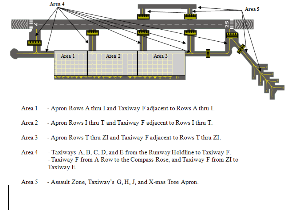
2.17.2.3. The weekly sweeper’s schedule by area is shown in Figure 1. Beginning with
Area I on Monday, Area II on Tuesday, etc.
Figure 2.1. Weekly Area Sweeping Schedule and Diagram.
2.17.2.4. Sweeper operators will not operate trucks mounted with metal bristles, as the
bristles tend to separate and create FOD.
2.17.2.5. When Aircraft Maintenance Unit (AMU) supervision determines that one or
more limited areas need to be swept, they will contact AM Ops and provide details. AM
Ops will determine the appropriate priority and dispatch the sweeper in accordance with
that priority. Note: This procedure applies only to aircraft taxi/tow routes and not
general areas or parking lots, etc.
2.17.2.6. If sweepers are not available or cannot adequately clean area to be swept,
Airfield Management will work with CE to sweep limited areas of major FOD
concentration by hand. NOTE: The Maintenance Operation Center will provide sweeper
crews as necessary for these areas.
18 LITTLEROCKAFBI13-250 29 APRIL 2010
2.17.3. Operations.
2.17.3.1. CE will provide a radio for the sweeper operator. Two-way radio contact must
be established with the control tower prior to entering the Runway, Assault Zone, and
Taxiways. The operator will monitor the radio at all times while on these areas. If radio
contact is lost, the operator will immediately and safely vacate the area and proceed to
AM Ops.
2.17.3.2. CE will ensure that all flight line sweeper operators have in their possession an
AF IMT 483, Certificate of Competency for Airfield Driving and a USAF Restricted
Area Badge (AF Form 1199), authorizing them access to all areas of the airfield.
2.17.3.3. Sweeper outages will be reported by LRS and/or CE to AM Ops as soon as the
information becomes known. Specify the nature of the maintenance problem and
expected in-commission time.
2.17.4. Special Emphasis.
2.17.4.1. Units possessing aircraft have the primary responsibility for the FOD program
in their aircraft parking areas. When assistance is required due to unusual circumstances
and to control potential FOD, units should contact AM Ops for sweeper support.
2.17.4.2. Close coordination will be maintained between CE and the Airfield
Management to support this instruction to the maximum extent.
2.17.5. Airfield Lighting Systems Inspection, Maintenance, and Reporting Procedures
2.17.5.1. Airfield Management will:
2.17.5.1.1. Conduct a daily nighttime/evening airfield lighting serviceability check.
2.17.5.1.2. Document airfield lighting discrepancies to include the date/time found,
who the outage was reported by/to, and follow-up actions until the discrepancy is
closed.
2.17.5.1.3. Report lighting outages and/or deficiencies to CE Electrical Systems for
correction.
2.17.5.1.4. Outages exceeding allowable tolerances and/or any airfield lighting
discrepancy which is considered a hazard to flight safety will immediately be reported
to CE for priority response.
2.17.5.1.5. Minor outages identified during non-duty hours which fall within
allowable tolerances and do not pose a hazard to flight safety may be reported the
following duty day.
2.17.5.2. CE Electrical Systems Personnel will:
2.17.5.2.1. Review AM’s airfield lighting discrepancy log.
2.17.5.2.2. Inspect airfield lighting systems Mon-Fri (except holidays) prior to
0900L.
2.17.5.2.3. Notify AMOPS when the lighting inspection is completed, of any
additional outages, and the status of fix actions until discrepancies are
repaired/closed.
LITTLEROCKAFBI13-250 29 APRIL 2010 19
2.17.5.2.4. Respond to airfield upon notification from AMOPS personnel of airfield
lighting discrepancies which exceed allowable tolerances and pose a hazard to flight
safety.
2.17.5.3. These procedures are established IAW AFIs. Deviations to these procedures
will be coordinated on an individual basis between CE Electrical Systems and AMOPS.
2.17.6. Mowing Operations: The normal mowing season is between March and October.
Mowing operations are completed by contract with CE serving as the Quality Assurance
representative. Airfield grass height will be maintained between 7 and 14 inches. Due to
sometimes unfavorable airfield conditions, mower operators must check in with AM
Operations prior to starting airfield mowing operations. AM Operations will notify the
appropriate agencies depending on the mowing locations. Mowers must contact tower
whenever mowing on the airfield.
2.17.6.1. Due to the closeness of the mowers to the AZ, mowers are required to get
preapproval from the tower before getting within 50ft of the AZ. While in this area,
mowers are required to maintain radio contact with the tower in case they are required to
vacate the area for aircraft landings/departures. Mowing operations around the AZ
should be conducted before wing flying to minimize delays to landing and departing
aircraft.
2.18. Runway Surface Condition (RSC) and Runway Condition Reading (RCR) Values.
2.18.1. AM Operations will conduct these checks based on current meteorological
conditions. Results of these checks will be reported to appropriate wing agencies for
dissemination to aircrews. When the airfield is open, AM Operations is responsible for
determining and reporting RSC/RCR as required IAW T.O. 33-1-23, Procedures for Use of
Decelerometer to Measure Runway Slickness, and LRAFB Plan 32-1002, Snow and Ice
Control. The RSC/RCR and any subsequent changes shall be relayed to tower, command
post, and base weather. Tower will notify other concerned ATC agencies. AMOPS will
send a NOTAM whenever the runway surface condition is other than dry.
2.19. Runway Inspections/Checks Procedures and Requirements.
2.19.1. Airfield Management will inspect the airfield daily prior to the start of flying
activities. Additional airfield checks will be accomplished as needed IAW AFIs. Normally,
AM Operations will perform airfield and RWY checks; however, other personnel may be
delegated the responsibility but must be trained and certified by the Airfield Manager or
designated representative prior to assuming duties.
2.19.2. AM Operations will conduct the following specific airfield checks:
2.19.2.1. Foreign Object Damage (FOD) and Bird Aircraft Strike Hazard (BASH): This
check will be accomplished daily before flying activities begin and as required
throughout the day.
2.19.2.1.1. AM Operations will conduct a FOD check, time and traffic permitting, of
the runway and taxiways before any fighter (excluding A-10) and KC-135R
lands/departs. Traffic permitting, tower will provide a call to AMOPS upon receiving
the inbound strip.

20 LITTLEROCKAFBI13-250 29 APRIL 2010
2.19.2.2. Airfield Lighting Serviceability: This check will be completed before the start
of NVG ops, the hours of darkness, or during the overt NVG window.
2.19.2.3. Runway Surface Condition/Runway Condition Reading will be conducted
when weather conditions or braking reports require or at pilots request.
2.19.2.4. In-flight and Ground Emergencies: See Para 6.19.1.
2.19.2.5. Check for conditions that could affect safe airfield operations during other
events, such as unauthorized aircraft landings, severe weather, airfield driving violations,
checks of construction areas, natural disaster (tornado, typhoon, earthquake, etc.).
2.19.3. When a RWY/TWY check is required, AM Operations will be notified as soon as
possible. Tower or AM Operations will suspend aircraft operations, in the affected area,
until the check is complete. Tower will give AM Operations priority access to the runway
and taxiways if FOD is reported or suspected to conduct FOD checks. If normal operations
cannot be immediately resumed following the check, AM Operations will close the affected
area and issue a NOTAM until operations can be resumed.
2.20. Engine Test/Run-Up Procedures. Maintenance personnel or Aircrews requesting engine
runs (throttles out of ground idle range) for maintenance and system checks shall first contact
MOC and then ground control for clearance. Due to radio limitations, 189th AW crews are
exempt from the requirement to contact MOC. Maintain radio contact with ground control until
the engine run is completed. Workload permitting, ground controllers will issue advisories to all
traffic in radio contact requesting to operate behind an aircraft performing an engine run;
however, aircraft commanders are ultimately responsible for aircraft safety when in proximity to
engine run operations. When the tower is closed or daily after wing flying, MOC will handle
requests for maintenance engine runs per paragraph 2.15.4 and 6.14.
2.20.1. Parking Rows B – Z, spots 1-5 in each row (except U1-2 and V1-2 for ATC tower
noise abatement), are authorized for idle power engine runs. Aircraft are authorized to
conduct above flight idle engine runs if the parking spot directly behind is vacant (to include
taxiing aircraft, vehicle, and pedestrian movement) during the duration of the engine run.
Note: Aircraft in Papa Row may conduct engine runs regardless of aircraft parked in Romeo
Row as the necessary distance requirement is met; however, spotters must still consider
vehicle and pedestrian movement.
2.20.2. Engine Runs Conducted by Aircrew Members. Note: Aircrews should not normally
conduct engine runs or propulsion system checks in lieu of maintenance personnel. All
engine run propulsion systems checks will be performed by qualified aircrew members and
accomplished IAW MDS specific -1 guidance. MDS specific -6 procedures will be
conducted by FCF crews only. The aircraft commander is ultimately responsible for ensuring
all potential danger areas are clear. When conducting engine runs at or above flight idle in
congested areas (i.e. aircraft parking rows), the aircraft commander will use an external
spotter (crewmember or maintainer) to monitor the aircraft and danger areas and advise the
crew of any hazards. The external spotter will connect to the aircraft’s interphone system
and close the crew entrance door. The external spotter will take a position outboard of the
left wing, in a position to see the pilot and the area behind the aircraft. After the engine run
is completed and clearance is given by the pilot, the external spotter can board the aircraft.
LITTLEROCKAFBI13-250 29 APRIL 2010 21
2.21. Noise Abatement Procedures. Formal noise abatement procedures are not applicable;
however, avoid overflying base housing and the school, both located south-southwest of the
runway. See Attachment 2 for VFR ground tracks.
2.22. Noise Complaints.
2.22.1. During duty hours (0730-1630L), refer all noise complaints to PA (DSN: 731-3601).
2.22.2. After duty hours, Command Post will record the information and forward it to the
public affairs office the next duty day.
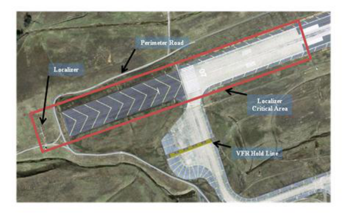
2.23. Protecting Precision Approach Critical Areas.
2.23.1. Localizer & Glideslope Critical Areas:
2.23.1.1. In addition to standard RWY hold lines, there are instrument hold lines and
illuminated instrument (INST) hold signs on TWYs F and G.
Figure 2.2. ILS/Localizer Critical Area.
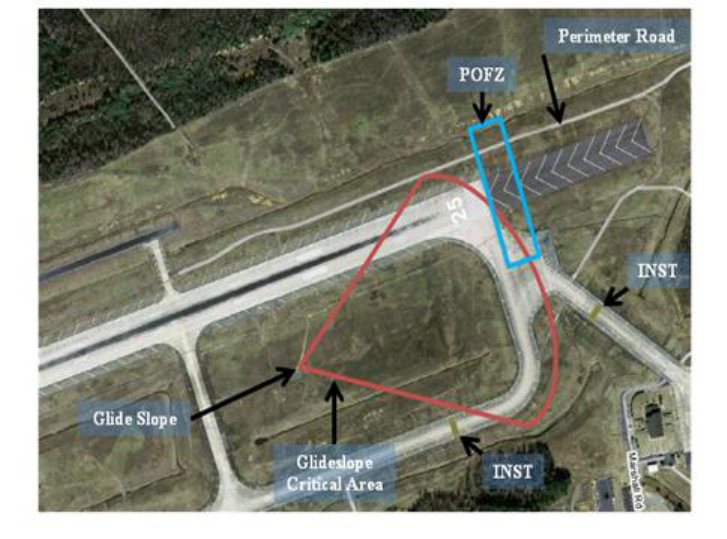
22 LITTLEROCKAFBI13-250 29 APRIL 2010
Figure 2.3. RWY 25 ILS/Glideslope and POFZ Critical Areas.
2.23.1.2. The INST hold signs are turned on when the reported weather conditions are
ceiling less than 800ft and/or visibility less than 2 miles. When the INST hold signs are
illuminated, tower shall prohibit aircraft or vehicles beyond the INST hold lines if an
arriving aircraft is inside the final approach fix (FAF) (This procedure is more restrictive
than FAA ORDER JO 7110.65 and AFIs). The following exceptions apply:
2.23.1.2.1. Aircraft may be in or over the localizer critical area while landing,
departing, exiting, or conducting missed approach. DO NOT allow aircraft to stop in
the critical areas unless an emergency exists.
2.23.1.3. When the reported weather conditions are ceiling less than 200ft and/or RVR
2,000ft or less (1/2 mile if RVR is not available) do not authorize vehicle or aircraft
operations in or over the localizer critical area when an arriving aircraft is inside 1 NM
from touchdown.
2.23.1.4. When weather conditions are such that the INST hold lines are NOT in effect,
but an arriving aircraft is conducting a "coupled approach" or “autoland” the tower shall
protect the appropriate critical area. Inform the aircraft when the appropriate critical
areas are not being protected. (Phraseology: "ILS CRITICAL AREA NOT
PROTECTED"). NOTE: Vehicles/aircraft must obtain tower clearance to enter either of
the critical areas when the instrument hold signs are illuminated.
2.23.2. Precision Obstacle Free Zone (POFZ):
2.23.2.1. The POFZ is an 800 foot wide by 200 foot long rectangular area centered on
the runway centerline, beginning at and extending outward from the threshold, designed
to protect aircraft flying precision approaches from ground vehicles and other aircraft

LITTLEROCKAFBI13-250 29 APRIL 2010 23
when the ceiling is less than 300 feet, or visibility is less than ¾ statute mile (or runway
visual range below 4,000 feet). See Figure 2.3.
2.23.2.2. The POFZ is considered clear even if the wing of the aircraft holding on a
taxiway waiting for runway clearance penetrates the POFZ; however, neither the fuselage
nor the tail may infringe on the POFZ.
2.23.2.3. IAW LRAFBI 13-202, Non-essential vehicle operators will obtain permission
from tower to enter the POFZ (which is penetrated while transiting the east end perimeter
road or holding short of the runway at Txy E) prior to entering the POFZ. Ground
vehicles essential to airport operations are excluded from this requirement. Essential
vehicles include those vehicles necessary for the maintenance of the airport and
navigation facilities, but do not include non-essential vehicles such as construction,
refueling vehicles, or mowers.
2.23.2.4. In the event that taxiing/parked aircraft or vehicles are not clear of the POFZ,
controllers are to provide traffic advisories only to the arriving aircraft regarding the
position of the offending aircraft/vehicles.
2.24. Airfield Restricted Areas.
2.24.1. Restricted areas: Areas on the airfield designated by the installation commander for
the protection of resources. The C-130 parking apron is a designated restricted area (parking
rows A through Y). Additionally, all aircraft maintenance hangars and the Christmas tree
parking apron are designated restricted areas when protection-level 3 resources or higher are
present.
2.24.2. Individuals must have a restricted area line badge (AF Form 1199) or be escorted by
someone who does before entering these areas. Contact unit security managers for specific
details.
2.25. Runway Suspension Procedures. Tower and/or AM Operations should temporarily
suspend RWY or AZ operations anytime an unsafe condition exists (e.g. dropped objects, FOD,
liquid spills, wildlife, etc). AM Ops will complete an airfield check of the affected area and
report status of the RWY/AZ prior to resuming operations. Note: AM Operations has authority
to impose airfield restrictions (close, suspend, or resume RWY/AZ or taxiway operations) as
necessary.
2.26. Airfield Closure Procedures. The process for closure requests outside of published
airfield operating hours can be found in AFI 13-204V3. The AOF/CC will coordinate all
closures with, at a minimum, 19 OSS/OSO, 314 OG/OGO, and 189 OG before requesting final
approval as instructed by AFI 13-204V3 and applicable supplements.
2.26.1. Will take control of the airfield when the control tower, AMOPS, and airfield
are closed. Otherwise, owner/user personnel will be actively involved in security of
their assets by providing internal control and surveillance for aircraft parking areas
and resources. Security response will be provided by SFS.
2.27. Airfield Opening Procedures.
2.27.1. Responsibilities:
2.27.1.1. AM Operations:

24 LITTLEROCKAFBI13-250 29 APRIL 2010
2.27.1.1.1. Will call 19 SFS via the hot line to obtain control of the airfield.
2.27.1.1.2. Will notify 19 AW/CP and 189 AW/CP of airfield opening. Note:
Control of the airfield will be transferred to AM Operations upon request. At that
time, all information of any personnel in the CMA will be given to AM Operations.
2.27.1.1.3. Will document on AF IMT 3616, Daily Record of Events, each vehicle by
call sign that is on the airfield plus any additional pertinent information relayed by
Security Forces.
2.27.1.1.3.1. Will advise the control tower via the Tower Net or Tower Hotline of
all vehicles within the CMA, by call sign, prior to opening.
2.27.1.1.4. Report for duty 1 hour prior to pre-coordinated ETA/ETD or scheduled
opening time and complete an airfield inspection/check and transfer control of the
airfield to tower 30 minutes prior to a pre-coordinated ETA/ETD or scheduled
opening time, whichever comes first.
2.27.1.2. Control Tower:
2.27.1.2.1. Will be operational and expect control of the airfield from AM Operations
30 minutes prior to a pre-coordinated ETA/ETD, or scheduled opening time.
2.27.1.2.1.1. Will receive control of the airfield from Airfield Management via
the Tower Net or Tower Hotline. At that time, the call sign of each vehicle within
the CMA will be relayed to the Tower.
2.27.1.2.1.2. Will confirm the location of all vehicles relayed by AM Operations
and request any other vehicles to check in if not already called by making the
following announcement to all agencies on the Tower Net: “Little Rock Air
Force Base airfield is open, contact Tower for approval onto the Controlled
Movement Area.”
2.28. Radio and Visual Blind Spots.
2.28.1. Radio: Occasionally, transmissions on the Clearance Delivery frequency are not
received by the tower from aircraft located in the Christmas Tree and/or the transient ramp
(Row “Z1” spots 3-5).
2.28.2. Visual: West of the jumbo hangar (bldg. 250) and the Christmas Tree apron.
2.29. Aircraft Rescue Fire Fighting (ARFF).
2.29.1. ARFF notifications will be accomplished IAW AFI 13-204V3_AMCSUP.
2.29.2. The ARFF capability degradation restrictions are defined by the ARFF/Airfield
Operations Restriction working group, and will be published separately in an Operations
Letter to be incorporated into applicable checklists and FLIPs as appropriate. The working
group is co-chaired by the OSS/CC and CES/CC, delegated no lower than their respective
deputies and will convene IAW AFI 13-204V3_AMCSUP.

LITTLEROCKAFBI13-250 29 APRIL 2010 25
Chapter 3
LOCAL FLYING AREAS
3.1. General Description of Local Terrain and Obstructions. The area surrounding Little
Rock AFB is generally flat with some rolling hills (400ft to 500ft MSL) west of the RWY. The
highest obstruction within 25 NM of Little Rock AFB is a television antenna (2,220ft MSL) 17.8
NM southwest, approximately in line with the RWY.
3.2. Local Flying Area.
3.2.1. Consists of a 600 NM radius around Little Rock AFB. Note: Flights in and around
the Warrior MOA and KAEX will also be considered local area for members of 34 CTS and
34 CTS certified Trainer/Mentors.
3.2.1.1. Restricted areas 2403A/B are located approximately five miles west of Little
Rock AFB (see Para 3.5.).
3.2.1.2. There are three drop zones (DZ) in the Little Rock AFB area: All American
(AADZ) located in R-2403A, which encompasses an AZ; Black Jack (BJDZ) located
approximately 19 miles NNE of Little Rock AFB and JAX DZ located just north of
RWY25/07 and at the west end of the AZ on Little Rock AFB (see Para 3.7.).
3.3. Designation of Airspace. The aerodrome is designated as Class D airspace. It
encompasses a 5.6 NM circle from the center of the airfield, from the surface to and including
2,800ft MSL. Two-way radio communication is required with ATC prior to entering the Class D
airspace and will be maintained until exiting the Class D airspace or a frequency change
approval is given by the tower. Little Rock Approach may use portion of the Class D airspace as
shown in the Little Rock AFB Tower and Little Rock Tower Coordination LOA, Attachment 2.
3.4. Fixed Wing Functional Check Flight (FCF) Area. The Little Rock AFB FCF local flying
area begins 30 NM from the Jacksonville TACAN (LRF) to the 600 NM boundary; on a line
from LRF through Jackson VORTAC (JAN), then clockwise to a line from LRF to Walnut Ridge
VORTAC (ARG); then due north of Walnut Ridge VORTAC to the area boundary. Normally,
an FCF will be performed under radar control and in the FCF area to the maximum extent
possible.
3.5. Restricted Areas.
3.5.1. R-2403 A/B is located 5-9 miles west of Little Rock AFB and can be active up to
16,000ft. The Department of the Adjutant General of the Arkansas Army National Guard
controls R-2403A/B. NOTAMs concerning R-2403A/B are found in the Enroute Special
Notice section under Memphis ARTCC. Little Rock AFB control tower will have R2403
active times on the DATIS as applicable.
3.5.1.1. When notified, Little Rock AFB AM Operations may process a local NOTAM
for the activation of R-2403A/B; however, IAW AFI 11-208, AM Operations is not
required to issue any NOTAM concerning R-2403A/B activity. The Camp Robinson
Range Officer coordinates all starts/stops/changes to operations in R-2403A/B with LIT
Approach Control. Requests to deactivate R-2403A/B, due to an emergency, will be
made through LIT Approach Control.

26 LITTLEROCKAFBI13-250 29 APRIL 2010
3.5.2. When R-2403B is active, instrument approaches to RWY 07 are not authorized.
Additionally, Category E circling to RWY 07 is not authorized. Note: Run-ins to AADZ
and AALZ are authorized. Use caution to stay north of N 34° 53.33, Declination Rd, which
denotes the weapons range on Camp Robinson, approximately 1.4NM south of the AADZ
southern boundary.
3.5.3. The Combat Arms complex and EOD detonation area are located 1-2 NM ESE of the
east end of RWY 25.
3.6. VFR Local Training Areas. N/A
3.7. Local Drop Zones. Procedures for local DZ and AZ use are contained in 19 AW
Supplement to AFI 11-2C-130, Vol 3, 314 AW Supplement to AFI 11-2C-130, Vol 3, and the
Little Rock AFB Aircrew Flimsy. EXCEPTION: See Paras 3.7.1.-3.
3.7.1. Jacksonville Drop Zone (JAX DZ): JAX DZ is located on the airfield (north of the
runway and west of the AZ) and consists of two DZs of varying dimensions. Contact 19
OSS/OSK for information and restrictions.
3.7.1.1. Use of JAX DZ requires prior coordination with the 19 OG/CC and specific
authorization of the 19 AW/CC. Before using JAX DZ, mission commanders will ensure
that 19 OSS/OSK briefs crewmembers and airdrop leaders.
3.7.1.2. JAX DZ is approved for day and night operations of heavy equipment, container
delivery system (CDS), and personnel (high altitude low opening and static line).
CARPS (computed aerial release points) should not fall south of the RWY. In the event
the CARP falls south of the RWY, approval must be obtained from the 19 OG/CC. Use
the LRF 275/7 at 1,900ft MSL for the emergency salvo area.
3.7.1.3. JAX DZ personnel and equipment drops require special emphasis by all parties
concerned to ensure the safety of the jumpers and ground personnel. All aircraft ground
movements shall be suspended on TWY F northward and west of TWY D (and vehicle
movements on tower controlled movement area) until Drop Zone Control Officer
(DZCO) advises tower personnel that the DZ is clear. DZCO shall maintain radio contact
with the tower on 275.8 and advise them when drops have terminated. Tower shall
approve parachute jumping with respect to known or observed traffic and issue advisory
information to the jump aircraft and to non-participating aircraft as necessary for the safe
conduct of the jump operation.
3.7.2. All American Drop Zone/Assault Zone: Scheduling for the use of the DZ/AZ located
in restricted area R-2403A, will be coordinated IAW LRAFBI 11-201. In the event of an
emergency, or to affect a cease-fire on R-2403A/B, contact LIT Approach Control and LZ
controller.
3.7.3. Black Jack Drop Zone: Scheduling for the use of the DZ will be coordinated IAW 11-
201.

LITTLEROCKAFBI13-250 29 APRIL 2010 27
3.8. Practice Approaches by Transient Aircraft. Transient aircraft may make practice VFR
or IFR approaches when base assigned or attached aircraft are flying in the tower or radar pattern
as long as they do not interrupt the base’s mission. HHQ directed missions, distinguished visitor
aircraft, Camp Robinson AAF helicopters (Guard Copter), and Air National Guard aircraft
assigned to the 188th Fighter Wing (call sign “Hawg” or “Tusk”) will be given priority over
other transient aircraft. If a formation flight, practice approaches by transient aircraft are
considered local operations and will be assigned priority IAW Para. 9.11.

28 LITTLEROCKAFBI13-250 29 APRIL 2010
Chapter 4
VFR PROCEDURES
4.1. VFR Weather Minimums. VFR weather minimums in the Little Rock AFB local flying
area are IAW AFI 11-202, Vol 3. To conduct VFR transition training in the Little Rock AFB
Class D airspace, the reported ceiling must be at or above 1,500ft AGL and 3 SM visibility. The
tower will discontinue VFR training when aircraft are no longer visible from the tower in any
portion of the VFR traffic pattern. Weather minimums for other than USAF aircraft will be IAW
FAA ORDER JO 7110.65.
4.2. VFR Traffic Patterns.
4.2.1. General Procedures:
4.2.1.1. The tower watch supervisor will determine the number of aircraft that can safely
operate in the VFR traffic pattern.
4.2.1.2. Formation flights conducting different type landings to the RWY, such as #1 full
stop, #2 and #3 low approach, should request and receive clearance for the “OPTION.”
Note: Aircraft within a formation flight are not authorized to conduct operations to
different landing surfaces.
4.2.1.3. For traffic pattern efficiency and safety, aircraft flying an approach at other than
normal airspeed ("NO FLAP" approach), shall inform air traffic control of their
intentions during the downwind leg of the radar or tower patterns.
4.2.1.4. Air traffic controllers will not approve a pilot's request or request a pilot to
conduct unusual maneuvers within the Class D airspace if they are not essential to the
performance of flight. Maneuvers identified in AFI 11-2C-130 Vol 3, applicable AFTTP
3-3, and this instruction, are considered to be operationally required for wing aircraft, and
are not classified as unusual maneuvers. All other requests will be denied unless
specifically approved by the 19 OG or designated representative (19 AW assets) or the
314 OG or designated representative (314 AW assets).
4.2.1.5. Aircraft are not authorized to conduct a GROUND-IDLE TOUCH-AND-GO or
a STOP-AND-GO when cleared for the “OPTION.” These landings must be specifically
approved by ATC.
4.2.1.6. Aircraft are authorized to operate at or below 250 KIAS while in the Class D
Airspace.
4.2.2. Rectangular Traffic Patterns (see Attachment 2): The traffic patterns will normally be
entered from the north of Little Rock AFB using a 45-degree entry leg to downwind. The
traffic pattern altitude is 1,400ft MSL. Any pilot deviation from the pattern altitude by more
than +/- 100ft MSL requires control tower notification.
4.2.2.1. RWY 25 Left Closed Traffic: Use of this traffic pattern is directed by the tower
as necessary, typically to sequence traffic due to formation high-speed downwind
recoveries to RWY 25, or during formation east-to-west All American Drop Zone run-
ins.

LITTLEROCKAFBI13-250 29 APRIL 2010 29
4.2.2.1.1. Turn left crosswind when safely airborne, but no earlier than the end of the
RWY. Downwind leg shall not exceed 2 NM miles south of airfield, unless
otherwise instructed by ATC. Aircrews will remain above 1,000’ AGL when Combat
Arms M-203 training is in progress. During EOD activations, aircrews will not
overfly the EOD area except when the EOD area is active for non-blast/fragment
producing explosives or ground burst simulator detonations only.
4.2.2.2. RWY 25 Right Closed Traffic: Turn right crosswind when safely airborne, but
no earlier than the end of the RWY, unless otherwise instructed by ATC.
4.2.2.3. RWY 07 Left Closed Traffic: Turn left crosswind when safely airborne, but no
earlier than the end of the RWY, unless otherwise instructed by ATC.
4.2.2.4. RWY 07 Right Closed Traffic: Turn right crosswind when safely airborne, but
no earlier than the end of the RWY. Downwind leg shall not exceed 2 NM miles south of
airfield, unless otherwise instructed by ATC. Aircrews will remain above 1,000ft AGL
when Combat Arms M-203 training is in progress. During EOD activations, aircrews
will not overfly the EOD area except when the EOD area is active for non-blast/fragment
producing explosives or ground burst simulator detonations only. Note: If traffic
permits, tower may authorize closed traffic (crosswind turn) prior to departure end of the
RWY.
4.2.3. Overhead Pattern (Attachment 2): Both conventional and jet aircraft may fly the
overhead patterns. The overhead traffic pattern altitude is 1,900ft MSL. When operating on
RWY 25, local C-130 aircraft will normally break left at the RWY numbers consistent with
wing aircraft priority; however, the break may be delayed (i.e. midfield, departure end), as
directed by ATC for safety or traffic reasons. All other aircraft will be issued a right break
IAW the IFR Sup, unless otherwise directed by ATC. Note 1: When the EOD area is active,
Rwy 25 left breaks from the overhead pattern will not be permitted except when the EOD
area is active for non-blast/fragment producing explosives or ground burst simulator
detonations only. Rwy 25 right breaks will be approved, traffic permitting. Note 2: To
comply with noise abatement, the preferred recovery for Rwy 07 overhead is left break.
Aircraft may perform Rwy 07 right break due to pattern saturation or in the interest of safety.
Note 3: For drop zone transitions, these procedures only apply to Blackjack DZ when Rwy
25 is active. During concurrent AADZ/BJDZ operations, overhead transitions are not
authorized from All-American.
4.2.3.1. Base assigned C-130 aircraft escaping visually from Blackjack DZ shall squawk
0322, beginning at the Initial Point (IP), to signal LIT and tower that an overhead
approach recovery is desired.
4.2.3.2. On DZ escape, maintain VFR (Day/Night 1500ft MSL), contact LIT, and request
own navigation to initial. Climb to 1,900’ MSL prior to turning initial.
4.2.4. To ensure protection of the overhead pattern, when applicable, tower will instruct
transient aircraft departing from LRAFB to maintain at or below 1,400ft MSL until the
departure end of the runway.
4.2.5. All American Run-in Procedures: When All American LZ/DZ operations are active
and C-130 aircraft are approved for the PLAYNS transition by LIT, the following procedures
go into effect:

30 LITTLEROCKAFBI13-250 29 APRIL 2010
4.2.5.1. Tower will:
4.2.5.1.1. Establish a south traffic pattern to de-conflict pattern traffic from
transitioning aircraft.
4.2.5.1.2. Release IFR departures IAW the Little Rock AFB & FAA Letter of
Agreement.
4.2.5.2. Transitioning C-130 aircraft will:
4.2.5.2.1. When cleared to AADZ by LIT, maintain at or above 3,000’ MSL until
PLAYNS (LRF 062/30), then descend and maintain 2,000’ MSL. When formation
lead is past TYV and at slowdown, aircraft may descend to drop altitude and
complete the run-in as stated in the Little Rock AFB Aircrew FLIMSY.
4.3. Assault Zone (AZ) Operations.
4.3.1. Use by other than base assigned C-130’s must be coordinated in advance with the 19
OG/CC.
4.3.2. Departures: Aircraft may depart the AZ on an IFR or VFR flight-plan.
4.3.3. Arrivals:
4.3.3.1. Aircraft must inform ATC of the landing surface as soon as possible (AZ or
RWY).
4.3.4. Weather minimums to request/receive approval to transition to the assault zone are the
same as circling minimums for the non-precision approach.
4.3.5. Single aircraft may land on the AZ by transitioning visually from non-precision
approaches to RWY 25/07. Weather minimums to request/receive approval to transition to
the assault zone are the same as circling minimums for the non-precision approach. Crews
must request the transition prior to commencing/receiving clearance for the instrument
approach (Little Rock Approach will clear the aircraft for the approach). In the case of
missed approach, crews will transition to the main runway (RWY 25/07) and execute
published missed approach or (alternate instructions).
4.3.5.1. Formations are not authorized to land to the AZ since Reduced Runway
Separation cannot be applied. Traffic permitting, aircraft within a formation requesting
to recover to the AZ must assume individual call signs and continue as single ships as
directed by ATC.
4.3.5.2. Formations are not authorized to depart the AZ unless prior coordinated with
ATC.
4.3.6. Tower approves or disapproves AZ approaches based on traffic and shall use the
following phraseology: "ASSAULT ZONE, CLEARED TO LAND/LOW APPROACH" or
"UNABLE ASSAULT ZONE" (Time permitting, give reason(s), and provide alternate
instructions, such as transition to RWY 25, etc.). Note: To the maximum extent possible,
consistent with pilot qualifications and aircraft performance, pilots will comply with tower’s
request to transition from one landing surface to another. (I.E. “UNABLE ASSAULT
ZONE, MAKE LOW APPROACH RUNWAY 25”)
4.3.7. After landing on the AZ, hold short of RWY 25/07 until given ATC instructions.

LITTLEROCKAFBI13-250 29 APRIL 2010 31
4.3.8. AZ operations shall be temporarily suspended anytime personnel or equipment are on
the AZ. Tower will coordinate with AM Operations to ensure expeditious removal of
personnel and equipment on or adjacent to the AZ to expedite its availability for use.
4.4. Helicopter Operations.
4.4.1. Helicopters may take off and land on any portion of the movement area depending
upon tower traffic. Due to uncontrolled vehicles and other aircraft operations, tower will use
caution when instructing helicopters to depart/land from other than the tower controlled
movement area. The tower may allow helicopters to cross the RWY at any point depending
upon other air traffic; however, helicopters shall not overfly any aircraft on the ground.
4.5. Special Procedures.
4.5.1. Simulated Flameout (SFO) Patterns: SFO patterns are not authorized at Little Rock
AFB. An actual flameout is an emergency and shall be provided priority handling. Tower
shall make every effort, time permitting, to clear the Class D airspace prior to an actual
flameout reporting “High Key.”
4.5.2. RANDOM STEEP APPROACH: A VFR maneuver allowing base assigned C-130
pilots to practice approaches and landings in a simulated hostile environment. This
maneuver is subject to tower approval and consists of a high altitude, steep spiral, and
descent over the airport to the RWY/AZ. Procedures are as follows:
4.5.2.1. The pilot shall request this approach from LRF tower at any point in the VFR
traffic pattern or inform LIT approach on initial contact of proposed approach altitude
(typically 4,500ft MSL) and the landing surface. Advise ATC, if other than left break
and one turn to final.
4.5.2.2. ATC shall relay any known traffic and issue transponder Mode 3 code 0333.
4.5.3. RANDOM SHALLOW APPROACH: These VFR maneuvers will be approved by
the tower only during periods of low-density traffic. Single-ship approaches are expected;
formation approaches require advance coordination and tower approval. Normally, pilots
will begin this maneuver from the VFR traffic pattern, and maintain radio contact with the
tower. Airspeed is at the pilot’s discretion, not to exceed 250 KIAS, unless the pilot advises
that a higher minimum speed is required.
4.5.3.1. Pilots shall inform the tower of the type approach (i.e. straight-in or abeam) and
obtain approval prior to departing the traffic pattern or beginning the maneuver if outside
the traffic pattern. Note: Tower may terminate this approach at any time and direct a
climb and entry into the VFR pattern.
4.5.3.2. RANDOM SHALLOW ABEAM: (Not authorized while RWY 07 is in use)
Random shallow abeam approaches must cross the runway from the north while
remaining east of the control tower and aircraft shall maintain at 900ft MSL (day) and
1,100ft MSL (night). Tower shall not approve random shallow abeam approaches when
the Combat Arms complex is active or during EOD activity.
4.5.3.3. RANDOM SHALLOW STRAIGHT-IN: Prior to turning final, aircraft will
climb to and maintain 1,400’ MSL within the Little Rock AFB Class D airspace. Aircraft
executing a straight-in from the visual pattern should obtain clearance from tower to

32 LITTLEROCKAFBI13-250 29 APRIL 2010
maneuver to the north/east and remain within 5 NM of the active runway. Descent to
900’ MSL (day) or 1,100’ MSL (night) is at pilot discretion.
4.5.3.4. Random shallow approaches (except a straight-in) will enter the Class D
airspace from the north.
4.5.3.5. Aircraft shall maintain avoidance criteria IAW AFI 11-202, Vol. 3 throughout
the maneuver.
4.5.4. Other Random Procedures:
4.5.4.1. HIGH ALTITUDE PENETRATION DESCENT (PD15, PD25, and PD30):
This is initially an IFR procedure, until IFR is canceled (outside the Class D Airspace).
Returning IFR aircraft may request the approach, and ATC will approve/disapprove
based on traffic. Final approach is completed using a random shallow straight-in
approach (see Para. 4.5.3.3.). The final altitude is 14,500ft MSL.
4.5.4.2. HIGH-SPEED DOWNWIND: Primarily used to enter a high-speed downwind
pattern when visually escaping from AADZ and BJDZ.
4.5.4.2.1. Entry point: LRF 350/12, regardless of runway in use.
4.5.4.2.2. DELETED.
4.5.4.2.3. Base assigned C-130 aircraft escaping visually from All American or
Blackjack DZ shall squawk 0311, beginning at the Initial Point, to signal LIT and
LRF tower that a high-speed downwind recovery is desired.
4.5.4.2.4. On DZ escape, maintain VFR (Day/Night 1500ft MSL), contact LIT, and
request own navigation or radar vectors to the downwind entry point.
4.5.4.2.5. At the downwind entry point, fly an approximate heading of 170 to enter
the downwind pattern, regardless of runway in use. Aircraft shall not proceed past 7
NM northwest until radio contact has been established with the tower and tower has
approved the high-speed downwind entry. (Phraseology: “DOWNWIND ENTRY
APPROVED”).
4.5.4.3. CARGO WEST: A VFR stereo route allowing predictable VFR flight, along
with flight following, from Little Rock AFB to Blackjack DZ and return to Little Rock
AFB. The final altitude is 14,500ft MSL.
4.5.4.3.1. DELETED.
4.5.4.3.2. DELETED.
4.5.4.3.3. DELETED.
4.5.4.3.4. AFI 11-202 and FAR procedures for VFR flight shall apply throughout the
entire route. If unable to comply with the VFR rules, aircrew shall advise ATC
4.5.4.4. BLACKJACK 19: A higher altitude SKE route with a block altitude of 16,000
through 17,000.
4.5.4.4.1. DELETED.
LITTLEROCKAFBI13-250 29 APRIL 2010 33
4.5.4.5. RANDOM SHALLOW TEARDROP: All teardrop approaches should
commence from the active RWY downwind entry point described in paragraph 4.2.2.,
unless otherwise directed by ATC.
4.5.4.5.1. When departing All American or Blackjack DZ, request clearance from
LIT ATC and maneuver north until cleared inbound by tower. Proceed inbound until
within 5 NM, then maneuver to align on the extended runway centerline. Descent to
at or below 900ft MSL (day) is at pilot's discretion.
4.5.4.5.2. Do not over fly any landing surface during the teardrop maneuver (i.e. fly
opposite direction overhead the runway for a late break turn) without explicit
approval from tower. Initiate a continuous turn to final when the aircraft is abeam the
landing threshold.
4.5.4.5.3. For night approaches, maintain 1,500ft MSL until within 5 NM then
descend to 1,100ft MSL at pilot's discretion.
4.6. Low Altitude Closed Traffic and Circling Approach Procedures. A maneuver that
allows pilots to practice circling maneuvers when a circling approach, to the opposite RWY,
cannot be approved. Pilots may request this maneuver from tower or LIT. The weather
minimums for low altitude closed traffic are transition weather minimums (1,500ft ceiling and 3
SM visibility). The maneuver begins with a non-precision instrument approach, followed by an
over-flight of the RWY along the RWY centerline, and closed traffic at circling MDA.
4.6.1. When aircraft are transferred to Little Rock AFB tower, the pilot will request low
altitude closed traffic as follows: ("JODY 63 REQUEST LOW ALTITUDE CLOSED")
Tower will approve or disapprove low altitude closed traffic based upon traffic conditions.
The phrase “LOW ALTITUDE CLOSED TRAFFIC APPROVED” is approval for an over-
flight of the RWY along the RWY centerline followed by closed traffic (at circling MDA) at
the departure end of the RWY. When disapproving low altitude closed traffic, tower will
provide alternate instructions. Note 1: When the aircraft begins low altitude closed traffic,
IFR is automatically cancelled the first time the aircraft crosses the landing threshold. Note
2: Air traffic controllers shall not allow aircraft conducting “LOW ALTITUDE CLOSED
TRAFFIC” to over-fly aircraft that are “POSITION AND HOLD.”
4.6.2. When weather conditions do not permit Low Altitude Closed Traffic (weather below
transition minimums), pilots may request a “Circling Approach” to RWY aligned with the
instrument approach procedure. This is an IFR maneuver and pilots are expected to comply
with all appropriate circling criteria, including keeping the RWY environment in sight. ATC
will expect pilots to commence this maneuver at the departure end of the RWY or as
instructed by ATC. For example: For RWY 25, pilots will be instructed to “CIRCLE
NORTHEAST FOR A RIGHT BASE” or “CIRCLE SOUTHEAST FOR A LEFT BASE TO
RWY 25.” For RWY 07; pilots will be instructed to “CIRCLE NORTHWEST FOR A LEFT
BASE TO RWY 07.”
4.6.3. Circling maneuvers will normally be north of the field to prevent traffic congestion
and to avoid flying over populated areas. Circling south of the field is not authorized except
for emergency situations or when directed by ATC for safety reasons.

34 LITTLEROCKAFBI13-250 29 APRIL 2010
4.7. Reduced Same Runway Separation Procedures.
4.7.1. RWY 25/07: Tower may use Reduced Same Runway Separation (RSRS) standards,
as outlined in AFIs, between base assigned or attached C-130 aircraft. Aircrews or air traffic
controllers may refuse RSRS anytime safety of flight may be jeopardized.
4.7.1.1. General procedures:
4.7.1.1.1. Weather must be at or above transition minimums (1,500ft ceiling and 3 mi
visibility).
4.7.1.1.2. Runway surface must be dry.
4.7.1.1.3. RSRS standards are only authorized between similar/compatible type
operations (departure behind a departure, full stop behind a full stop, full stop behind
a departure, touch and go behind a touch and go, low approach behind a low
approach, touch and go behind a departure, touch and go behind a low approach, full
stop behind an OPTION).
4.7.1.1.3.1. Full Stop following a Full Stop: The preceding C-130 must be at the
appropriate separation down the RWY before the succeeding C-130 crosses the
landing threshold.
4.7.1.2. C-130 RSRS Minimums:
4.7.1.2.1. Sunrise to sunset: 5,000ft.
4.7.1.2.2. Sunset to sunrise: 6,000ft.
4.7.1.2.3. C-130 formation landings: 6,000ft between formations or formations and
single ship.
4.7.1.3. RSRS shall not apply when:
4.7.1.3.1. Aircraft (succeeding/preceding) are cleared for the OPTION (except full
stop behind an OPTION), or the preceding aircraft is cleared for a STOP AND GO.
4.7.1.3.2. Aircraft are cleared for a low approach behind a touch and go or a touch
and go behind a full stop.
4.7.1.3.3. A pilot declares an emergency.
4.7.2. RWY and AZ Separation Procedures: The following minimum separation shall apply
between C-130 aircraft using the AZ and the RWY.
4.7.2.1. A C-130 landing on the AZ behind a C-130 landing or departing RWY 25 shall
not pass abeam the RWY 25 threshold until the preceding C-130 has landed or the
departure is airborne and 5,000ft down the RWY.
4.7.2.2. A C-130 landing on RWY 25 behind a C-130 landing on the AZ shall not cross
the RWY 25 threshold until the preceding C-130 has landed on the AZ. If the AZ is
planned low approach, ensure that the preceding (AZ) aircraft passes abeam TXY H
before the succeeding aircraft crosses the RWY 25 landing threshold.
4.7.2.3. A C-130 landing on RWY 07 behind a C-130 landing on AZ shall not cross
RWY 07 threshold until the preceding C-130 passes the 6,000ft remaining marker.

LITTLEROCKAFBI13-250 29 APRIL 2010 35
4.7.2.4. A C-130 landing on the AZ behind a C-130 landing or departing RWY 07 shall
not pass abeam the landing threshold of RWY 07 until the preceding C-130 has landed or
the departure is airborne and passed 6,000ft remaining marker. Note: If the preceding
aircraft in paragraph 4.7.2.4. is a stop-and-go, touch-and-go, or low approach, use
departure separation criteria.
4.7.2.5. A C-130 landing on RWY 07/25 behind a C-130 departing the AZ shall not
cross the RWY 07/25 threshold until the AZ departure is airborne.
4.7.2.6. A C-130 departing the AZ shall not begin takeoff roll until a C-130 making a
full stop landing on RWY 07/25 is landing assured.
4.7.2.7. For C-130 aircraft using the AZ only, apply same RWY separation procedures
IAW FAA ORDER JO 7110.65. An arriving aircraft must have taxied clear of TWY H
or J before the succeeding aircraft is allowed to cross the AZ threshold or begin takeoff
roll.
4.8. Line up and Wait Procedures.
4.8.1. To expedite traffic, aircraft may be taxied into takeoff position to hold on one surface
while traffic is landing or taking off on the other surface. ATC shall issue traffic advisories
IAW FAA ORDER JO 7110.65.
4.8.1.1. HQ AFFSA and the FAA have issued a waiver (on file at 19 OSS/OSA) which
allows one base assigned or attached aircraft at a time to taxi into position and hold at an
intersection on the main RWY during the hours of darkness when the controller can visually
see the aircraft holding in position and uses established memory aids.
4.9. Intersection Departures. RWY intersection departures may be made from the following
TWYs:
4.9.1. RWY 25: TWYs C, D, H, and J.
4.9.2. RWY 07: TWYs B, C, and H.
4.9.3. The distance remaining from the intersection to the end of the RWY will not be
transmitted to locally based aircraft except upon pilot request. Distances remaining from
intersections are depicted in Attachment 4.
4.9.4. To avoid delaying AZ departures, aircraft using TWY D intersection should be ready
for departure upon reaching the RWY. If a delay is anticipated at TWY D, continue to TWY
E for departure.
4.9.5. To avoid delaying aircraft exiting the AZ from TWY H, aircraft using TWY C for
departures should be ready for departure upon reaching the RWY. If a delay is anticipated,
continue to TWY E for departure.
4.9.6. Whenever an aircraft is parked on the secondary or tertiary Hot Cargo Pad (the
compass rose or intersection of taxiways Alpha and Foxtrot) the following restrictions apply:
Runway 25 Intersection departures are only authorized from Taxiway Delta or the full length
of Runway 25. Runway 07 full length departures are prohibited. This is to mitigate an
increased risk to operations as the result of an ORM Assessment conducted as part of the
MAJCOM approved HCP waivers.

36 LITTLEROCKAFBI13-250 29 APRIL 2010
4.10. Night Vision Goggle (NVG) Operations. NVG operations are authorized to Runway
25/07 and Assault 249/069. Note: Requests to turn the runway and assault zone lights on or off
shall be made through the tower and will be taken in the following priorities: Non NVG capable
aircraft arriving from off station, local a/c not utilizing NVGs, then NVG aircraft. Final approval
authority before changing the lighting configuration is the Tower WS.
4.10.1. During airfield covert lighting operations, RSRS cannot be applied.
4.10.1.1. NVG operations to an IR/covert only lighted airfield are not authorized while
non-participating aircraft are within the Class D airspace.
4.10.1.2. Tower shall turn off airfield lighting only after non-participating or non-NVG
aircraft have departed the Class D airspace.
4.10.2. Non-NVG flight training may be conducted to a normal/overt lighted landing surface
while NVG flight training is being conducted to the other, IR/covert only lighted, landing
surface. Reduced Same Runway Separation is authorized only when Rwy25/07 is overt
lighted.
4.10.2.1. DELETED.
4.10.2.1.1. Taxiways H and J will be turned off whenever the Assault Zone is the
IR/covert only landing surface and turned on when Runway 25 is the IR/covert only
landing surface.
4.10.2.1.2. DELETED.
4.10.2.1.3. Airfield lighting on the normal/overt lighted surface will normally be
operated IAW FAA ORDER JO 7110.65 during local night operations, unless
otherwise requested. The approach lights will be turned off when requested.
4.10.3. Little Rock AFB air traffic controllers do not use NVGs while controlling aircraft
in the air or on the ground. Controllers will only use NVGs to enhance situational
awareness of the airfield. Use of NVGs will be at the discretion of the WS. The interior
tower cab lighting shall be adjusted if using NVGs to observe NVG operations.

LITTLEROCKAFBI13-250 29 APRIL 2010 37
Chapter 5
IFR PROCEDURES
5.1. Air traffic control service at Little Rock AFB.
5.1.1. Air Traffic Control Service is provided by the following agencies:
5.1.1.1. Memphis Center (ZME)
5.1.1.2. Little Rock Approach Control (LIT)
5.1.1.3. Little Rock AFB Control Tower (LRF)
5.2. IFR Control. IFR traffic above 15,000ft MSL is controlled by ZME. LIT provides
approach and departure control services to aircraft within approximately a 30 NM radius of LIT
VORTAC up to and including 15,000ft MSL. LRF tower is responsible for providing VFR ATC
service within the Little Rock AFB Class D Airspace. The operating hours for Little Rock
AFB’s airfield are contained in the IFR Supplement.
5.2.1. LIT provides basic radar service to all aircraft transitioning to and from Little Rock
AFB and will consist of safety alerts, traffic advisories, limited radar vectoring when
requested by the pilot, and sequencing VFR traffic with IFR and other participating VFR
traffic.
5.2.2. Due to high traffic volume, all arriving VFR aircraft will contact LIT Approach
Control for sequencing prior to entry into Little Rock AFB airspace.
5.2.3. Although basic radar service is not mandatory, radar use enhances the overall air
traffic system and is encouraged. If service is not desired, the pilot must state "negative radar
service" on initial call-up. ATC will assume all VFR aircraft are participants unless informed
otherwise.
5.3. Radar Traffic Patterns. As vectored by LIT approach control.
5.4. Radar Vector to Initial Procedures. As directed by LIT ATC.
5.5. Local Departure Procedures. Note: Little Rock AFB does not have any published
Departure Procedures (DP).
5.5.1. Charlie Climb-out Instructions:
5.5.1.1. CHARLIE CLIMB-OUT: A departure clearance (not a DP) assigned by tower
or LIT to aircraft requesting to depart and enter the radar traffic pattern, or remain in the
radar traffic pattern for instrument approaches. The clearance limit is LRF and it replaces
other missed approach instructions.
5.5.1.1.1. Aircraft cleared for Charlie Climb-out will fly RWY heading, climb and
maintain at or below 1,400ft until departure end of RWY (maintains overhead traffic
pattern protection), then climb and maintain 2,000ft, at 2 DME turn right heading 360
(RWY 25) or left heading 360 (RWY 07), contact local channel 9 (257.625 or
120.125 or LIT frequency as assigned).

38 LITTLEROCKAFBI13-250 29 APRIL 2010
5.5.1.1.2. In the event the TACAN is out of service, aircraft will execute the Charlie
Climb-out as published, except turn right heading 360 (RWY 25) at LIT 352/14 or
turn left heading 360 (RWY 07) at LIT 007/15.
5.5.2. Departure Control Instructions: Formation departures shall be changed to departure
control frequency before takeoff. Any emergency instructions from the tower, after the
formation has changed to departure frequency, will be broadcast on GUARD frequency(ies).
5.5.3. When pilots request a local IFR clearance to LIT that was not part of the original
flight plan, controllers will issue ―Cleared to Little Rock Adams Field as filed‖ in lieu of
reading the full route clearance over the radio. Although radar vectors are common, aircrews
should understand that ATC expects the pilot to fly the stereo routing to LIT as stated in the
Flimsy (LRF248008 BEGEE TYV LIT). Pilots may request LRF or LIT to fly direct to LIT
Adams Field. All requests will be taken on an individual basis.
5.6. Availability/Restrictions for Surveillance (ASR) Approaches and Precision Approach
Radar (PAR) Approaches/Monitoring. LRAFB does not have an ASR or PAR approach.
LITTLEROCKAFBI13-250 29 APRIL 2010 39
Chapter 6
EMERGENCY PROCEDURES
6.1. General. Specific procedures cannot be prescribed for every situation that might be
considered an emergency. As a general rule, an emergency includes any situation, which places
an aircraft, people, and/or property in danger or distress. If it is unclear whether a situation is an
emergency, treat it as an emergency.
6.2. Types of Declared Emergencies. When an aircrew declares an emergency it will be
classified as one of the following emergencies: in-flight, ground, or physiological.
6.3. Operation of Primary Crash Alarm System (PCAS) and Secondary Crash Net (SCN).
6.3.1. Primary Crash Alarm System: IAW AFIs, the primary crash circuit is limited to two-
way communications with the fire department, AM Operations, and the flight surgeon
(during clinic operational hours). Additional agencies may have receive-only capability.
Note: The flight surgeon’s office is only staffed during normal duty hours. After normal
duty hours, the fire department will make the necessary calls for medical personnel.
6.3.2. Secondary Crash Net: IAW AFIs, the secondary crash net is operated by AM
Operations. All information received over the PCAS shall be transmitted verbatim over the
SCN.
6.3.3. To ensure system reliability, the PCAS and SCN shall be tested daily between 0830
and 0900L.
6.4. On/Off-Base Aircraft Mishaps or Emergencies. In the event of an aircraft mishap or
emergency, tower will:
6.4.1. On-Base: Immediately activate the Primary Crash Alarm System (PCAS) providing
all available information regarding the emergency. Information should include: type of
emergency, call sign, type aircraft, location, estimated time of arrival, landing RWY,
personnel on board, fuel on board, current wind, hazardous cargo, nature of emergency, and
any other pertinent information.
6.4.1.1. Suspend normal operations when an aircraft mishap is observed or when normal
operations would conflict with an emergency aircraft's priority.
6.4.1.2. The ground controller will notify ground traffic and taxiing aircraft to "HOLD
POSITION" when emergency (crash) equipment moves out to respond to the emergency.
Normally, ground operations will resume after the emergency has been terminated;
however, ground movements may be approved on a case-by-case basis, prior to
emergency termination, after coordination with the Incident Commander/fire chief.
6.4.1.3. Relay additional information to crash crew personnel over the two-way radio.
All references to the crash site will include location or grid map coordinates if available.
6.4.2. Off-Base: In the event an off-base mishap report is received from a credible source,
(ATC facility, Sheriff’s Department, etc.) the following shall apply: Note: Anytime the
source of a mishap report is questionable, tower shall notify command post to verify the
40 LITTLEROCKAFBI13-250 29 APRIL 2010
authenticity of the report. During these circumstances, tower will activate the PCAS as
directed by the command post or base officials.
6.4.2.1. Activate the PCAS.
6.4.2.2. The tower will notify other aircraft to remain clear of the mishap area unless
otherwise advised by the Incident Commander or Command Post.
6.4.2.3. The designation and responsibilities of the Incident Commander can be found in
LRAFB Plan 91-204, Mishap Response Plan. The Fire Chief is normally the Incident
Commander; however, the Incident Commander will be designated by the 19 MSG/CC.
6.5. External Stores Jettison Areas. The jettison area is located on the eastern edge of R-2403
A/B, and west of the Rock Ridge and Cato Mountain Ridge in Faulkner County. Controllers
shall not determine the exact time or location of external stores release).
6.5.1. The primary emergency jettison area is located on the LRF 275/7 NM at a desired
altitude of 1,900ft MSL.
6.5.2. Aircraft operating VFR will notify the tower of an emergency situation requiring
jettisoning and may obtain an approach control frequency for vectors to the jettison area.
6.5.3. When aircraft are “own navigation,” the aircraft should maintain RWY heading (250
MH) for 7 NM miles and turn north for 3 1/2 NM miles to the jettison area.
6.6. Fuel Dumping Procedures. Fuel dumping procedures and area will be determined by
coordination with ZME or LIT Approach.
6.7. Emergency Arresting/Barrier Gear Procedures. There is no arresting/barrier gear
equipment located on the airfield.
6.8. Hot Brake Areas and Procedures. The designated hot brake areas are TWYs A, B, C, D,
and E. Specific instructions will be relayed by ATC as given by the Incident Commander.
6.9. Abandonment/Bailout of Aircraft. The controlled abandonment area is located on the
LRF 275/7 NM.
6.10. Personnel/Crash Locator Beacon Signal/Emergency Locator Transmitters (ELT)
Response Procedures.
6.10.1. The tower will notify ZME (Mission Coordinator), Command Post, and AM
Operations when a Personnel/Crash Locator Beacon Signal or ELT signal is received or
when an aircraft reports receiving such a signal.
6.10.2. The PCAS and SCN will be activated for a Personnel/Crash Locator Beacon Signal
or ELT signal only if emergency response is desired by command post.
6.11. Combat Aircraft Arm/De-arm/Hot Gun/Hung Ordnance/Hot Flares/Chaff Bundles
6.11.1. Any of the above operations will be conducted on the Arm/De-arm pads located on
Taxiways A and E.
6.11.2. If landing RWY 07: Hung ordnance area is on the on TWY E hammerhead with
aircraft positioned in such a way that the guns/rockets are pointing not less than 003 degrees
or more than 030 degrees. Note: Operations on RWY 25 will be suspended.

LITTLEROCKAFBI13-250 29 APRIL 2010 41
6.11.3. If landing RWY 25: Hung ordnance area is on the is on TWY A hammerhead with
the aircraft positioned in such a way that the guns/rockets are pointing not more than 245
degrees or less than 240 degrees. Note: Operations on RWY 07 will be suspended.
6.12. Hydrazine Parking Area. Unless the Incident Commander directs another area, the
hydrazine parking area is TWY A (RWY 25) or TWY E (RWY 07).
6.13. Unlawful Seizure of Aircraft Procedures. Unlawful seizures of aircraft procedures are
contained in LRAFB Plan (OPLAN) 502, Air Operations Security.
6.14. Aircraft Engine Start and Movement (Anti-hijacking). When the tower is open,
aircraft requesting engine start for flight shall contact clearance delivery. Aircraft being towed,
requesting engine start for maintenance, or requesting taxi shall contact ground control. If an
aircraft is observed moving and two-way radio contact cannot be established, the tower will
implement anti-hijacking procedures. When the tower is closed or outside of wing flying
(normally 0200-0600L), 19 AW MOC will handle requests for maintenance engine run clearance
and aircraft towing. Before the start of wing flying, tower will contact MOC for a listing of all
engine runs/tows on the airfield.
6.15. Wind Limitations on the Control Tower. The tower will be evacuated when wind
reaches 75 knots or more.
6.16. Evacuation of ATC and AM Operations Facilities.
6.16.1. ATC: When the tower (Bldg 214) must be evacuated due to fire, bomb threat,
excessive wind, tornado sighted or reported moving toward the base, or other unsafe
conditions requiring ATC personnel to leave, tower will broadcast the following message on
ALL frequencies, including emergency frequencies: “ATTENTION ALL AIRCRAFT,
LITTLE ROCK AFB TOWER IS BEING EVACUATED, ALL TAXIING AIRCRAFT
RETURN TO PARKING. ALL AIRCRAFT IN THE VFR PATTERN MAINTAIN VFR,
DEPART THE PATTERN TO THE NORTH, CONTACT LITTLE ROCK APPROACH ON
257.625/120.125.”
6.16.1.1. Only emergency response vehicles are permitted on the tower controlled
movement area. AM Operations has approval authority for other vehicles.
6.16.1.2. While the tower is evacuated, NAVAIDS can continue to operate with internal
monitoring as long as pilot or maintenance reports show the NAVAID is operating
normally IAW AFIs.
6.16.1.3. Tower evacuates to either the base of the tower, Bldg 120 (primary), or Bldg
314 (secondary) as necessary.
6.16.2. AMOPs: When AMOPs (Bldg 120) personnel must be evacuated due to fire, bomb
threat, or other unsafe conditions, AMOPs will relocate to the alternate AMOPs facility in
Bldg 314.
6.16.2.1. Transient Aircrews will be directed to alternate facility by Transient Alert.
6.17. Alternate Facilities.
6.17.1. AM Operations: The alternate AM Operations facility is located in Bldg 325. It is
equipped with the SCN, all necessary landlines, radios, and computers with LAN
connections.
42 LITTLEROCKAFBI13-250 29 APRIL 2010
6.17.2. ATC: No alternate ATC facility is available.
6.18. Combat Arms and Explosive Ordnance Disposal (EOD) Area
6.18.1. The Combat Arms range complex and EOD detonation area are located 1 to 2 NM
ESE of the east end of RWY 25.
6.18.2. Combat Arms and/or EOD personnel will coordinate with 19 OSS/OSAT (7x3416)
prior to detonating any explosive. Combat Arms range coordination is only required for
activation of the M-203 range.
6.18.2.1. Combat Arms and EOD personnel will contact tower via “Crash” Net/Tower
Net or Tower telephone (7-3416) prior to activating range (live fire or detonation) and at
the termination of operations.
6.18.2.2. AM Operations will issue a local NOTAM indicating flight restrictions over
Combat Arms range complex and EOD area.
6.18.2.3. Combat Arms and EOD personnel will notify 19 OSS/OSO and Tower when
range activities have been cancelled.
6.19. Emergency Airfield Checks.
6.19.1. Following an aircraft emergency, a check of the RWY and TWYs (appropriate
sections) is required anytime foreign objects are reported or suspected of being present
(dropped objects, foreign debris, liquid spills, etc). Examples of emergencies requiring
checks are blown tires, hydraulic leaks, reported loss of antennas, panels or cowlings, or
turbine disintegration. Note: During emergency aircraft recoveries, the Airfield Manager or
designated representative has the authority to waive the RWY check if in their opinion the
potential for FOD does not exist.
LITTLEROCKAFBI13-250 29 APRIL 2010 43
Chapter 7
AIRFIELD VEHICLE (CMA)/PEDESTRIAN OPERATIONS
7.1. Responsibilities
7.1.1. Radio Discipline: All personnel shall exercise professional communications
procedures when operating radio equipment. Radios shall be utilized for official business
only.
7.1.2. All vehicles entering the Controlled Movement Area (CMA) shall be Tower Net or
Crash Net equipped. Those vehicles that are not Tower or Crash Net equipped will not be
allowed to enter the CMA unless escorted by a vehicle with Tower or Crash Net capability.
7.1.3. IAW LRAFBI 13-202, the Deputy Airfield Manager is the OPR for the airfield
driving program at Little Rock AFB. AM Operations will only train and certify unit airfield
driving program managers.
7.1.4. Unit Commanders must ensure that personnel authorized to drive on the airfield are
trained and certified IAW LRAFBI 13-202, Airfield Driving, and vehicular operations are
kept to a minimum.
7.1.5. Unit Airfield Driving Program Managers will train unit trainers or drivers to drive on
the airfield. All airfield drivers shall meet the requirements established in LRAFBI 13-202,
Airfield Driving.
7.2. Controlled Movement Area (CMA. The purpose of this area is to establish positive
control over ground traffic. See Attachment 3.
7.3. Vehicle Control Area (VCA. See Attachment 3.
7.4. Airfield Driving Requirements. See LRAFBI 13-202, Airfield Driving.
7.5. Privately Owned Vehicles (POV) and Government Leased Vehicles (GLV. Guidance
on POVs and GLVs can be found in LRAFBI 13-202, Airfield Driving.\
7.6. Vehicle Traffic Procedures. See LRAFBI 13-202, Airfield Driving.
7.7. Vehicular Call Signs. Vehicular (radio) call signs must be utilized IAW LRAFBI 33-101,
Radio Call Signs.
7.8. Airfield Driving Violations and Penalties. See LRAFBI 13-202, Airfield Driving.
7.9. Emergency Vehicle Operations.
7.9.1. The deployment (standby) position of crash and rescue equipment shall be determined
by the fire chief depending upon the nature of the emergency, personnel, and equipment
limitations. The normal standby position is on the ramp adjacent to the intersections of
TWYs B and F, C and F, and D and F.
7.9.2. Crash and rescue equipment have the right-of-way over all vehicular and aircraft
movement from the time emergency (crash) vehicles move out to cover the emergency until
the emergency is terminated. Crash response vehicles shall not proceed onto the active RWY
without clearance from the control tower.
44 LITTLEROCKAFBI13-250 29 APRIL 2010
7.10. Airfield Construction/Work Crew/Maintenance Restrictions See LRAFBI 13-202,
Airfield Driving.

LITTLEROCKAFBI13-250 29 APRIL 2010 45
Chapter 8
FLIGHT PLANNING PROCEDURES
8.1. Flight Plans. Aircraft departing USAF installations must have a flight plan on file with
AM Operations prior to flight IAW General Planning instructions. A DD Form 175, Military
Flight Plan; DD Form 1801, DOD International Flight Plan; or any other authorized form may
be used as outlined in AFI 11-202, Volume 3, General Flight Rules or FLIP General Planning
must be used. Original flight plans will not be accepted by radio.
8.1.1. Locally filed flight plans:
8.1.1.1. Can be amended by any means, provided a flight plan is on file at AM
Operations. Additionally, an aircraft commander on a stopover or divert flight plan may
re-file or amend the flight plan with AM Operations by any means provided AM
Operations can verify the original flight plan.
8.1.1.2. Must list the pilot in command and appropriate signature of approving
authority. All other crew members should be listed on the crew orders.
8.1.2. Transient/stopover/divert flight plans:
8.1.2.1. Flight plans may be re-filed or amended with AM Operations via any means
(radio, telephone, fax, etc) provided AM Operations personnel can verify an original
flight plan was filed. AM Operations may verify original flight plans by contacting the
original departure location via telephone or flight plan processing computer.
8.2. Emailing or Faxing Flight Plans.
8.2.1. Aircrews will contact AMOPs (7-6123) approximately five minutes after sending the
flight plan to confirm receipt. Aircrew orders do NOT need to be sent to AMOPs with the
flight plan if maintained at the local flying unit. Indicate the location of the orders in in the
block “Crew/Passenger List” on the DD Form 175 (ie, On File at 53 AS). Changes to the
crew orders including “Half-time” crew swaps will be annotated on the orders at the flying
unit.
8.3. Responsibilities.
8.3.1. AM Operations will:
8.3.1.1. File the flight plan, making only those changes needed for computer acceptance.
When changes to the flight plan are necessary, a full clearance read-back (FRC) will be
entered in as the first item in remarks.
8.3.1.2. Provide flight following when flight plans are filed.
8.3.2. ATC shall forward to AM Operations the following:
8.3.2.1. All arrival/departure times.
8.3.2.2. After initial contact, all known information regarding civil aircraft attempting to
land without a Prior Permission Required (PPR) number.

46 LITTLEROCKAFBI13-250 29 APRIL 2010
Chapter 9
MISCELLANEOUS PROCEDURES
9.1. Airfield Operations Board (AOB. The AOB is established IAW AFIs as a forum for
discussing, updating, and tracking various activities in support of the wing flying mission. The
AOB meets quarterly or as directed by the 19 OG/CC. The Airfield Operations Flight
Commander (AOF/CC) normally conducts the AOB.
9.1.1. AOB members include, but are not limited to designated representatives from the
following units/agencies:
Table 9.1. AOB Membership
19 OG/CC (Chair)
19 AW/SEF
41 AS/CC
19 OG/OGV
314 OG/CC
50 AS/CC
19 OSS/CC
314 AW/SEF
53 AS/CC
19 OSS/OSA (Recorder)
314 OG/OGV
61 AS/CC
19 OSS/OSAA
189 OG/CC
34 CTS/CC
19 OSS/OSAT
189 AW/SEF
48 AS/CC
19 OSS/OSAM
19 CS/CC
62 AS/CC
19 OSS/OSW
19 CES/CEPD
29 WPS/CC
154 TRS/CC
19 SFS/CC
FAA (LIT, NLR)
9.1.2. The following mandatory items must be reviewed:
9.1.2.1. Quarterly Review Items:
9.1.2.1.1. Airspace (terminal, en-route, and special use) as changes occur.
9.1.2.1.2. ATC Flying Procedures (new, revised, and seldom used) as changes occur.
9.1.2.1.3. Military, FAA, and/or Host Nation concerns.
9.1.2.1.4. AOF (Flight Support, AM, and ATC) Staffing and Proficiency.
9.1.2.1.5. ATCALS (flight insp schedule, ATCALS equip problems, status,
upgrades, etc.).
9.1.2.1.6. Airfield Environment: Review airfield activities, problems, and programs
such as:
9.1.2.1.6.1. Number and status of permanent/temporary airfield waivers.
9.1.2.1.6.2. Status of deteriorating airfield/runway conditions (inspection trends,
foreign object damage/tire damage comparisons).
9.1.2.1.7. Airfield projects (Project list should include title, project number, wing
priority number, cost, source of funding, status, OPR, and estimated completion date).
LITTLEROCKAFBI13-250 29 APRIL 2010 47
9.1.2.1.8. Status of airfield driving program.
9.1.2.1.8.1. Include specific units to be inspected next quarter and the results of
unit inspections during the current quarter.
9.1.2.1.9. TERPS, as changes occur.
9.1.2.1.10. Runway intrusions/Controlled Movement Area (CMA) violations.
9.1.2.1.11. HATRs.
9.1.2.1.12. Air Installation Compatibility Use Zone (AICUZ).
9.1.2.1.13. Local Aircraft Priorities.
9.1.2.1.14. Aircraft Parking Plan.
9.1.2.1.15. SII Checklists.
9.1.2.1.16. Open ATSEP Problem/Observation Status.
9.1.2.2. Semi-Annually:
9.1.2.2.1. (May and October) Mid Air Collision Avoidance Program (MACA).
9.1.2.3. Annually:
9.1.2.3.1. Airspace (terminal, en route, and special use airspace).
9.1.2.3.2. ATC/Flying Procedures (new, revised, rescinded and seldom used).
9.1.2.3.3. Local Operating Procedures (LOP) (validate the need to keep, revise, or
delete).
9.1.2.3.3.1. LOAs (April).
9.1.2.3.3.2. Base Instructions (July).
9.1.2.3.3.3. OIs (October).
9.1.2.3.3.4. OPLANs (January).
9.1.2.3.3.5. Status of the Annual Airfield Waiver Package.
9.1.2.3.3.6. Aircraft Parking Plan.
9.1.2.3.3.7. TERPS instrument procedures.
9.1.2.3.3.8. Engine Run Procedures.
9.1.3. AOB Working Group: The AOB Working Group is convened by the 19 OG/CC when
necessary to staff specific ATC problems requiring rapid response or coordination. The
working group will consist of AOB members as designated by the 19 OG/CC depending
upon the issue at hand. The AOF will notify AOB members selected to attend the working
group after coordination with the 19 OG/CC.
9.2. Notice to Airmen (NOTAM) System Procedures. AM Operations will transmit all
required NOTAMs as necessitated by current airfield restrictions. NOTAMs will be processed
via the Defense Internet NOTAM Service IAW AFI 11-208, Department of Defense Notice to
48 LITTLEROCKAFBI13-250 29 APRIL 2010
Airmen (NOTAM) System. In the event the base server is not working, NOTAMs will be
processed by Keesler or Barksdale AFB AM Operations.
9.2.1. The tower is designated as the NOTAM monitoring facility, IAW AFIs.
9.2.2. AM Operations will notify the tower and use the NOTAM notification checklist each
time a NOTAM has been updated. When passing the NOTAM number, AM Operations will
also pass what the NOTAM covers.
9.3. Flight Information Publication (FLIP) Accounts and Procedures for Requesting
Changes. AM Operations receives and issues FLIPs for the following agencies; 19 OG/OGV,
19 OSS/OSW, 19 OSS/OSO, 19 OSS/OSA, 19 OSS/OSAT, 19 OSS/OSAM and Command Post.
The 314 AW, 189 AW, 48 AS, 53 AS, 62 AS, 41AS, 50 AS, 61 AS, and 29 WPS maintain their
own FLIP accounts. Units should contact their unit FLIP manager for FLIP account changes
requirements.
9.4. Waivers to Airfield/Airspace Criteria. Airfield/Airspace waivers are reviewed annually
and briefed at the AOB. 19 CES/CEPD is the OPR for the Airfield Waiver Program and 19
OSS/OSA is the OPR for Airspace Criteria. Further guidance can be found in the AMC Airfield
Waiver Policy for Implementing UFC 3-260-01, Airfield and Heliport Planning and Design.
9.5. Prior Permission Requested (PPR) Procedures. Little Rock AFB is PPR only for all
transient aircraft except those aircraft listed in paragraph 3.8., Air Evacuation, and Armed Forces
Courier aircraft. Transient aircraft visiting Little Rock AFB must obtain a PPR number no
earlier than 14 days and no later than 72 hours prior to arrival. A PPR number is valid +/-30
minutes of the proposed estimated arrival time.
9.6. Arriving Air Evac Notification and Response Procedures.
9.6.1. Tower shall notify AM Operations when Air Evac aircraft are 15 NM from landing.
9.6.2. Upon notification/arrival of any Air Evac aircraft, AM Operations will notify 19
AW/CP. Command post will notify hospital, fire department, and rescue protection.
9.7. Unscheduled Aircraft Arrivals.
9.7.1. ATC will contact AM Operations for permission to grant an unscheduled aircraft
arrival.
9.7.2. AM Operations will grant or deny permission for unscheduled aircraft arrivals IAW
local checklists and directives.
9.8. Distinguished Visitor (DV) Notification Procedures. When a DV is inbound to Little
Rock AFB, AM Operations will complete the DV Checklist and notify tower, protocol, 19 AW
or 189 AW CP (as applicable), Transient Alert, Base Weather, and the Airfield Manager. If the
DV is a code 4 or higher, AM Operations will also notify Security Forces.
9.8.1. Known DV Requirements: 19 AW Protocol will ensure all known DV handling
requirements are promptly forwarded to 19 AW/CP.
9.8.2. Workload permitting, tower will notify AM Operations of known DV arrivals no later
than 15 flying miles from the airport. After notification from tower, AM Operations will
immediately notify command post of the pending DV arrival.

LITTLEROCKAFBI13-250 29 APRIL 2010 49
9.8.3. No-notice Requirements: As soon as possible after becoming aware of a no-notice
DV arrival, tower shall notify AM Operations. AM Operations will immediately notify
command post upon receipt of the estimated time of arrival (ETA).
9.8.4. At no time will safety of flight be jeopardized to provide priority handling for a DV
aircraft.
9.8.4.1. Arriving and departing DV aircraft will be sequenced and handled on a first-
come, first-served basis consistent with the local aircraft priorities listed in paragraph
9.11. Note: When priority handling of DV aircraft is in the best interest of the 19 AW,
the 19 AW/CC/CV, 19 OG/CC, 19 OSS/CC, or the AOF/CC may direct priority handling
of DV aircraft over any 19 AW aircraft which normally are authorized higher priority.
9.8.4.2. Requests for priority DV handling will be made through command post to the
tower.
9.8.4.3. Upon receipt of a DV priority request, tower will complete all necessary actions
to allow the unimpeded taxi, takeoff, or landing of the DV aircraft consistent with the
local aircraft priorities listed in paragraph 9.11.
9.9. Dangerous/Hazardous Cargo. These procedures are in addition to those contained in
AFJI 11-204, Operational Procedures for Aircraft Carrying Hazardous Material. Taxi routes
and other procedures applicable to hazardous material and contaminated aircraft are established
for use at Little Rock AFB.
9.9.1. Notification of inbound aircraft carrying hazardous cargo may be received from the air
terminal operations center, tower, pilot-to-dispatch message, flight service, etc. AFJI 11-204
requires aircraft carrying hazardous cargo or inert devices to indicate type cargo in the
remarks section of the DD Form 175, Military Flight Plan. A base agency receiving
information on an inbound aircraft carrying hazardous cargo will relay all available
information to AM Operations. AM Operations will notify and keep the appropriate agencies
updated.
9.9.2. Parking for hazardous cargo aircraft will be IAW LRAFBI 13-205, Aircraft Parking
Plan.
9.10. Wear of Hats. Hats are not authorized on the Little Rock AFB flight line. This restriction
is an effort to reduce Foreign Object Damage (FOD) risk to aircraft. IAW LRAFBI 21-140,
Foreign Object Damage and Dropped Object Prevention Programs, exemptions are as follows:
9.10.1. Protocol duties when hats are appropriate (i.e. greeters).
9.10.2. Security forces and emergency personnel when headgear/hats are required.
9.10.3. Aircraft maintenance personnel when protective/weather headgear. Note: All
personnel wearing hats and/or headgear must remove all head garments/gear in the vicinity
of aircraft engine intakes, exhausts, props wash, and jet blasts, as loose garments can cause
serious damage to aircraft engines.
9.11. Local Aircraft Priorities.
9.11.1. The 19 OG/CC, 19 OSS/CC, AOF/CC, or designated representative will coordinate
any change to the application of these priorities with the tower.

50 LITTLEROCKAFBI13-250 29 APRIL 2010
9.11.1.1. Emergencies
9.11.1.2. Other Missions as identified in FAAO JO 7110.65
9.11.1.3. FAA Flight Check aircraft
9.11.1.4. Higher Headquarter (HHQ) directed missions requesting priority. Note: HHQ
missions shall inform clearance delivery and tower of their higher headquarters mission
and their desire for priority. (“LITTLE ROCK TOWER, BULL 25, HIGHER
HEADQUARTERS MISSION, REQUESTING PRIORITY.”)
9.11.1.5. All American DZ runs, formation
9.11.1.6. All American DZ runs, single ship
9.11.1.7. Distinguished visitors
9.11.1.8. Local formation instrument or overhead recoveries
9.11.1.9. Formations with controlled departure times (CDT). Note: On initial call-up,
aircrews shall inform clearance delivery of their CDT. Aircrews will advise the
appropriate controller of any subsequent CDT change. Aircrews are cautioned that
changing a CDT after taxi may result in a departure delay.
9.11.1.10. Formation downwind recoveries off of a DZ.
9.11.1.11. Single aircraft with controlled departure time
9.11.1.12. Formations and close interval sequence departures without controlled takeoff
times.
9.11.2. Controlled Departure Time (CDT): On initial call-up, aircrews shall inform
clearance delivery of their CDT. Aircrews will advise the appropriate controller of any
subsequent CDT change. Aircrews are cautioned that changing a CDT after taxi may result
in a departure delay.
9.11.3. HHQ missions shall inform clearance delivery and tower of their higher headquarters
mission and their desire for priority. (“LITTLE ROCK TOWER, BULL 25, HIGHER
HEADQUARTERS MISSION, REQUESTING PRIORITY.”)
9.12. Lost Communication Instructions.
9.12.1. In the event of two-way radio failure while in tower’s Class D airspace, Squawk
7600 and expect a green light gun signal from tower approaching 5-mile final, or during base
turn.
9.12.2. Under radar control: If no transmissions are received for 1 minute in the radar
pattern or 15 seconds on final, attempt to contact Tower on 269.075 and proceed VFR
towards Little Rock AFB. Squawk 7600 and look for a green light gun signal while on final
from the Tower.
9.12.2.1. VMC: If able to maintain flight in VMC continue flight under VFR and return
to Little Rock AFB.
9.12.2.2. IMC: If VFR recovery is not practical, intercept and proceed via the LRF 13
DME arc until joining the TACAN, ILS or NDB final approach course. Maintain the last
assigned altitude (or higher if required by the MEA/MVA, etc.) until established on final

LITTLEROCKAFBI13-250 29 APRIL 2010 51
and complete the approach as published. Look for the tower to provide a green light gun
signal.
9.12.3. Aircraft on DZ Runs: Reference Aircrew Flimsy.
9.13. Standard Climb-out Instructions. Little Rock AFB standard climb-out instruction is the
Charlie Climb-out as described in paragraph 5.5.1.1.
9.14. Opposite Direction Take-offs and Landings. Tower must obtain releases for IFR
opposite direction departures from LIT approach control. Approval is granted on a case-by-case
basis IAW LIT LRF LOA.
9.14.1. Arrival versus arrival: When simultaneous arrivals to opposite runways are in
progress, the succeeding aircraft may approach no closer than 6 miles from the runway end
until the first aircraft has landed or has commenced a minimum 45 degree turn away from the
opposite direction aircraft.
9.14.2. Arrival versus Departure/Low Approach: An aircraft on final approach may come
no closer than 6 miles from the runway end until the departing aircraft is airborne and has
commenced a minimum 45 degree turn.
9.15. Breakout/Go Around/Missed Approach Procedures.
9.15.1. Breakout/Go Around will be as instructed by ATC.
9.15.2. Low/Missed Approach: When making a low approach or missed approach, LRF or
LIT will instruct aircraft to "EXECUTE CHARLIE CLIMBOUT, (reason, if necessary).”
9.15.3. Formation Alternate Missed Approach Instructions: Formations requesting alternate
missed approach instructions will be issued "FLY RWY HEADING, CLIMB AND
MAINTAIN AT OR BELOW 1,400ft UNTIL DEPARTURE END OF RUNWAY, THEN
CLIMB AND MAINTAIN 2,000ft," or as otherwise instructed by ATC.
9.16. Flight Line Smoking Policy Smoking is prohibited on Little Rock AFB Flight Line
except at designated smoking locations along Flight Line Drive.
9.17. Civilian Aircraft Operations. Civilian aircraft may use base navigational aids and tower
services. Practice approaches (IFR/VFR) are not authorized during wing flying (base assigned or
attached). Outside of wing flying, civil aircraft may make low approaches only. Note: For
other than a low approach, approval must be obtained IAW AFR AFI 10-1001, Civil Aircraft
Landing Permits. If an unauthorized aircraft lands at Little Rock AFB, the tower will activate
the primary crash alarm system.
9.17.1. Use of Little Rock AFB by civil/general aviation is not authorized. Only the
Installation Commander or designated representative can grant exceptions to this policy.
9.17.1.1. Except for emergencies, no civil aircraft will land without approval of the 19
AW/CC or designated representative.
9.17.1.2. Requests for civil aircraft landing permits will be processed through
Headquarters USAF/XOOCA IAW AFI 10-1001. Note: Under certain conditions, civil
aircraft landing permits may be processed through 19 OSS/OSA for Installation
Commander approval.
52 LITTLEROCKAFBI13-250 29 APRIL 2010
9.17.2. Unauthorized landings present a distinct security risk to Little Rock AFB. If a pilot
files a flight plan to and lands at Little Rock AFB without first obtaining prior permission,
the 19 AW/CC or designated representative may categorize the landing as unauthorized in
IAW AFI 10-1001.
9.17.3. When a civil aircraft, without a PPR requests permission to land, AM Operations will
inform the tower watch supervisor that no prior approval has been obtained and the aircraft is
to be denied landing rights.
9.17.4. If the pilot of a civil aircraft declares an emergency and needs to land at Little Rock
AFB, the tower watch supervisor/controller-in-charge will allow the aircraft to land, direct
him to clear the active runway and hold position, and notify AM Operations of location. In
this situation, the tower shall activate the PCAS to inform base agencies of both an IFE and
an unauthorized aircraft landing.
9.17.4.1. Upon receiving the information from the PCAS, AM Operations will
immediately ring the secondary crash net. 19 SFS will dispatch a security team to the
aircraft to maintain security of the aircraft and crew and, if necessary, conduct follow-on
actions as directed by the Incident Commander.
9.17.4.2. AM Operations supervisor will respond to the aircraft and coordinate with ATC
to ensure the aircraft is held in position until 19 SFS responds.
9.17.4.3. AM Operations will notify the AOF/CC.
9.17.4.4. AM Operations will have Transient Alert provide a vehicle to the aircraft and
standby to escort and/or park the aircraft.
9.17.4.5. The Airfield Manager or designated representative will proceed to the aircraft
to determine landing validity.
9.17.4.6. The responding representative will interview the pilot and obtain a written
circumstantial report, copies of pilot’s license, driver’s license, aircraft registration, and
copies of reports taken by other responders such as FAA, Security Forces, or Secret
Service.
9.17.4.7. Once the interview is completed the category of landing will be ascertained (the
installation commander or a designated representative will identify an unauthorized
landing as either an emergency landing, an inadvertent landing, or an intentional landing)
and appropriate labor, material, etc. cost will be assessed according to AFI 10-1001 and
appropriate report sent to HQ USAF XOO/CA.
9.17.4.8. The AOF/CC will update the 19 OG/CC and 19 AW/CC.
9.18. Civil Use of Military NAVAIDS. Civilian aircraft may use Little Rock AFB NAVAIDs.
9.19. Aero Club Operations. Little Rock AFB does not have an Aero Club.
9.20. Weather Dissemination and Coordination Procedures – Hazardous/Severe Weather
Notification Procedures and Lightning Response Weather dissemination and coordination
procedures will be IAW AFI 10-206, Operational Reporting.
9.20.1. Wind Information: Wind information shall be transmitted to aircraft as outlined in
AFIs; however, variable wind information, as described in AFIs, is not required to be issued

LITTLEROCKAFBI13-250 29 APRIL 2010 53
to base assigned or attached aircraft. Variable wind information shall be issued to transient
aircraft.
9.20.2. IAW LRAFB Plan, 15-101, Weather Support Plan, when base weather issues a
weather advisory, watch, or warning, AM Operations will record and transmit the
information over the SCN.
9.21. Airfield Snow Removal Procedures. 19 CES is the OPR for snow removal operations.
Airfield snow removal operations will be conducted IAW LRAFB Plan 32-1002, Snow and Ice
Control.
9.22. Bird/Wildlife Control – BASH. AM Operations shall mitigate BASH hazards as outlined
in LRAFB (BASH) Plan 91-202 and locally developed checklists. Mitigation may include
vehicle horns, pyrotechnics, propane cannons, and the use of shotguns or a recommendation to
depredate.
9.23. Bird Hazard Notification System.
9.23.1. AM Operations and the control tower will mitigate BASH hazards and restrict
operations in accordance with procedures outlined in LRAFB (BASH) Plan 91-202.
9.24. DELETED.
9.25. Taking of Photographs on the Airfield. Cameras will not be brought into restricted
areas supporting PL1, 2, or 3 resources unless approval has been granted by the group
commander owning the resources or by the 19 AW/Public Affairs Division in writing. Cell
phones equipped with a camera feature are not to be used for photography in restricted areas
without proper authorization. Airfield Management has received approval from PA to take
pictures on any portion of the airfield. See LRAFBI 31-101, Little Rock AFB Installation
Security Instruction for specific details.
9.26. Joint Readiness Training Center (JRTC) Ground Operations. JRTC aircraft will
normally conduct operations on TWY G and the Christmas Tree. JRTC personnel will
accomplish marshaling and aircraft handling. JRTC aircraft may use the transient ramp only
after coordination with the airfield management.
9.27. Mid-Air Collision Avoidance Program (MACA. The goal of the MACA Program is to
enhance the safety of pilots with whom we share airspace. The purpose of the program is to
educate civilian pilots about Little Rock AFB flying operations and military pilots about civilian
flying operations.
9.27.1. Little Rock National/Adams Field airport is located 12 NM miles south of the
airbase. The traffic patterns are separated; however, certain maneuvers can bring aircraft into
close proximity with individuals in other patterns.
9.27.2. North Little Rock airport is 7 NM miles southwest of the base, and Camp Robinson
airport is 8.3 NM miles southwest of the base. Visual and instrument traffic patterns to Little
Rock AFB are north of RWY 25/07 in order to minimize conflicts with other area traffic.
9.27.3. Toneyville NDB is located 5.6 NM miles from the approach end of runway 25, and is
the final approach fix for the NDB approach. A high volume of civil and military air traffic
passes this fix. In addition, the NDB is also used for holding patterns at or above 2,000ft
MSL.

54 LITTLEROCKAFBI13-250 29 APRIL 2010
9.27.4. Potential Conflict Area: Highway 67/167 makes a convenient visual landmark for
aircraft traveling between Little Rock and Searcy, Walnut Ridge, or Jonesboro. The highway
passes through the Little Rock AFB Class D airspace and crosses the final approach course to
RWY 25, just inside the Toneyville NDB. This area has historically been a potential conflict
area and pilots are advised to be extremely vigilant when operating in this area.
9.28. Quarterly Joint Airfield Inspection. The purpose of the inspection will be to note
hazards, identify new short and long range requirements, validate previously identified
maintenance requirements and identify items that could have safety of flight connotations. This
inspection will provide an avenue for identifying and eventually prioritizing issues impacting
safe operations and mission accomplishment. Participants will be the Airfield Manager or
Deputy Airfield Manager, ATC, Safety, TERPs liaison (if available), and 19 CES (community
planner, pavements engineer, horizontal shop, and electrical shop). Note: The annual Airfield
Waiver Inspection will be completed simultaneously with the 2nd Quarter Quarterly Joint
Airfield Inspection.
9.29. Annual Airfield Certification/Safety Inspection. The purpose of the inspection will be
to note any potential hazards and validate previously identified hazards for status (removed or
remaining). In addition, it acts as a standardized inspection program to validate whether Little
Rock airfield meets standards and elevates the status of the airfield facilities to wing leadership.
This inspection will be completed simultaneously with the Quarterly Joint Airfield Inspection
each September.
9.29.1. The Airfield Certification/Safety Inspection Checklist listed in 13 series AFIs will be
used. Brief results at the AOB and maintain a copy on file for 12 months.
9.29.2. Participants will be the Airfield Manager, 19 CES (community planner, pavements
engineer, horizontal shop, and airfield lighting), and 19 AW/SEF. Representatives from
ATCALS maintenance, Weather, Security Forces, and the TERPS liaison (if available) are
highly encouraged to participate to provide technical expertise in their area of responsibility.
9.29.3. The 19 AW/CC will review/coordinate on the formal report and indicate whether the
airfield meets USAF standards. If not, identify corrective action being taken and estimated
“Get Well” dates.
9.30. Hearing Protection. Personnel operating on the flight line and near machinery producing
loud noise for extended periods of time will maintain at least one set of ear plugs on their person.
9.30.1. The following limits apply to all personnel routinely exposed to hazardous noise
IAW 29 CFR 1910.95. Routine exposure is defined as exposure to hazardous noise
(>85dBA) for 30 days per year. Reference 19 AMDS/SGPB (Bio-Environmental) survey
data for equipment not listed below (987-7398).
9.30.1.1. Wear double hearing protection (plugs and muffs/comm sets):
9.30.1.1.1. When within 100 feet (one aircraft parking spot or four 25ft parking ramp
blocks) of an aircraft with 1 or more engines operating or APU/GTC running.
9.30.1.1.2. When operating/starting APU/GTC, -95 and -60 power carts.
9.30.1.1.3. All aircrew members accomplishing engines running offload/onload
duties will wear double hearing protection within 100 feet of the aircraft. Active

LITTLEROCKAFBI13-250 29 APRIL 2010 55
Noise Reduction (ANR) headsets may be considered double hearing protection for
this purpose.
9.30.1.2. Wear single hearing protection (plugs or muffs/comm sets):
9.30.1.2.1. When within 25 feet (one parking ramp concrete block) of all operating
(excluding -95/-60 power carts, see para. 9.30.1.1.2.) or in industrial environments
with noise exceeding 85 dBA.
9.30.1.2.2. When operating/working in areas within 100ft (one aircraft parking
spot/four 25ft parking ramp concrete blocks) of aircraft with at least one engine
and/or the APU/GTC operating.
9.30.1.2.3. When operating/working between 100 and 500 feet of an aircraft with
four engines operating.
9.30.1.2.4. Passengers being onloaded/offloaded with engines running are only required
to wear single hearing protection.
9.30.1.3. Personnel transiting/working in vehicles while on the flight line (with windows
rolled up) or enclosed offices are not required to wear hearing protection.
9.30.1.4. DELETED.
9.30.1.5. For exercise purposes, personnel operating in MOPP 4 within 500 feet of
hazardous noise (aircraft engines or APU) are not required to wear hearing protection.
Exception: within 100 feet of an aircraft with engines running – doff Kevlar helmet and don
double hearing protection.
9.30.1.6. Personnel transiting hangers are not required to wear hearing protection.
9.31. DELETED.
9.32. Adopted IMTs/Forms. AF IMT 1199, Restricted Area Line Badge, AF IMT 3616, Daily
Record of Events, DD175, Military Flight Plan, and DD1801 DOD International Flight Plan.
GREGORY S. OTEY, Colonel, USAF
Commander
56 LITTLEROCKAFBI13-250 29 APRIL 2010
Attachment 1
GLOSSARY OF REFERENCES AND SUPPORTING INFORMATION
References
AFI 10-206, Operational Reporting, 15 October 2008
AFI 10-1001, Civil Aircraft Landing Permits, 1 September 1995
AFI 11-202 Volume 3, General Flight Rules, 5 April 2006
AFI 11-218, Aircraft Operations and Movement on the Ground, 11 May 2005
AFI 13-217, Drop Zone and Landing Zone Operations, 10 May 2007
AFI 24-301, Vehicle Operations, 1 November 2008
AFJI 11-204, Operational Procedures for Aircraft Carrying Hazardous Material, 11 November
1994
AFMAN 33-363, Records Management, 1 Mar 2008
AFMAN 91-201, Explosive Safety Standards, 11 November 2008
AFJMAN 11-208, Department of Defense Notice to Airman (NOTAM) System, 1 August 2004
AFMS 13E1, Air Force Manpower Standard, Airfield Operations Flight, 24 September 2007
LRAFBI 11-102, Aircraft Parking Plan, 8 May 2007
LRAFBI 13-201, Airfield Sweeper Procedures, 7 August 2006
LRAFBI 13-202, Airfield Driving, 5 June 2006
LRAFBI 15-101, Base Weather Support Plan, 24 August 2009
LRAFBI 21-101, Crashed, Damaged, or Disabled Aircraft Recovery Procedures, 19 October
2007
LRAFBI 21-140, Foreign Object Damage and Dropped Object Prevention Programs, 8
February 2007
LRAFBI 31-101, Little Rock AFB Installation Security Instruction, 13 January 2005
LRAFB OPLAN 32-1002, Snow and Ice Control, 3 November 2009
LRAFB OPLAN 91-202, Bird Aircraft Strike Hazard Plan, 26 October 2009
LRAFB OPLAN 91-204, LRAFB Mishap Response Plan, 18 December 2009
LRAFB OPLAN 502, Air Operations Security, 15 March 2010
OSAT OI 13-201, Air Traffic Control, 1 November 2009
OSAA OI 13-213, Airfield Management, 1 November 2009
AOF OI 13-1, Airfield Operations Flight Standard Operating Procedures, 17 August 2009
FAA ORDER JO 7110.65, Air Traffic Control, 11 February 2010
LITTLEROCKAFBI13-250 29 APRIL 2010 57
LOA, Little Rock Air Traffic Control Tower and Little Rock Air Force Base Tower, 2 November
2009
Abbreviations and Acronyms
AADZ/LZ—All American Drop Zone/Landing Zone
AETC—Air Education and Training Command
AFJI—Air Force Joint Instruction
AGE—Aerospace Ground Equipment
AGL—Above Ground Level
ALS—Approach Lighting System
ALSF—Approach Light System with Sequenced Flashing Light
AMC—Air Mobility Command
AMOPS—Airfield Management Operations
ANG—Air National Guard
AOB—Airfield Operations Board
AOF—Airfield Operations Flight
AS—Airlift Squadron
ASR—Surveillance Approaches
ATC—Air Traffic Control
ATCALS—Air Traffic Controls and Landing Systems
ATIS—Automatic Terminal Information Service
AW—Airlift Wing
AZ—Assault Zone
BASH—Bird Aircraft Safety Hazard
BJDZ—Black Jack Drop Zone
CES—Civil Engineering Squadron
CMA—Controlled Movement Area
COL—Combat Off-load
CS—Communications Squadron
DME—Distance Measuring Equipment
DV—Distinguished Visitor
DZ—Drop Zone
DZCO—Drop Zone Control Officer
58 LITTLEROCKAFBI13-250 29 APRIL 2010
ELT—Emergency Locator Transmitter
ETL—Engineering Technical Letter
FAA—Federal Aviation Administration
FAF—Final Approach Fix
FCIF—Flight Crew Information File
FCF—Functional Check Flight
FLIP—Flight Information Publication
FOD—Foreign Object Damage
FPCON—Force Protection Condition
HATR—Hazardous Air Traffic Report
HHQ—Higher Headquarters
HIRL—High Intensity Runway Lights
HQ—Headquarters
IFR—Instrument Flight Rules
IMC—Instrument Meteorological Conditions
IR—Infrared
JRTC—Joint Readiness Training Center
LIT—Little Rock Approach Control
MACA—Mid-air Collision Avoidance
MDA—Minimum Descent Altitude
MH—Magnetic Heading
MOC—Maintenance Operations Center
MSL—Mean Sea Level
NDB—Non Directional Beacon
NM—Nautical Mile
NORDO—No Radio
NVG—Night Vision Goggles
OG—Operations Group
OSS—Operations Support Squadron
OSS/OSA—Operations Support Squadron/Airfield Operations Flight
PAPI—Precision Approach Path Indicators
PCAS—Primary Crash Alarm System
LITTLEROCKAFBI13-250 29 APRIL 2010 59
PPR—Prior Permission Required
RCR—Runway Condition Reading
RSC—Runway Surface Conditions
RSRS—Reduced Same Runway Separation
RVR—Runway Visual Range
RWY—Runway
SCN—Secondary Crash Net
SFS—Security Forces Squadron
SM—Statute Mile
SOF—Supervisor of Flying
TACAN—Tactical Air Navigation
TWY—Taxiway
VFR—Visual Flight Rules
VMC—Visual Meteorological Conditions
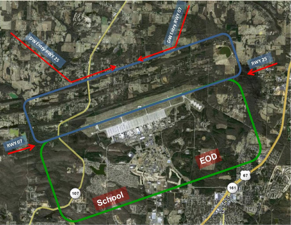
60 LITTLEROCKAFBI13-250 29 APRIL 2010
Attachment 2
FIXED WING TRAFFIC PATTERNS DIAGRAM
Figure A2.1. LRAFB VFR Traffic Pattern.
A2.1. Rectangular (1,300’ MSL).
A2.2. Enter Pattern only from the North.
A2.3. Tower approval required for southern pattern. Avoid overflight of school, base
housing, and EOD when active.
A2.4. Remain east of Batesville Pike Road (LRF 3 DME) in the northern pattern.
A2.5. Aircraft, including helicopters, will not over-fly aircraft in/on the Christmas Tree,
Compass Rose, TWYs A - G, H, J, or the AZ.
LITTLEROCKAFBI13-250 29 APRIL 2010 61
Attachment 3
CONTROLLED MOVEMENT AREA & VEHICLE CONTROL AREA
A3.1. CONTROLLED MOVEMENT AREA (CMA):
A3.1.1. The following areas on the airfield are part of the Tower CMA: Runway, Assault
Zone, Taxiways Alpha through Echo, grassy areas north of Taxiway Foxtrot (except fuel
facilities outlined in Attachment 4), and the eastern portion of Taxiway Foxtrot beginning at
the instrument (INST) hold line. Additional areas include Taxiway Golf from Echo to the
entrance (marked by the INST hold line) of the Christmas Tree Apron. The CMA continues
west, north, and east from these areas to the tree line around the airfield. All operators must
comply with CMA restrictions and procedures IAW LRAFBI 13-202.
A3.1.2. Vehicle operators intending to operate within the CMA must establish direct two-
way radio contact with the Tower (or contact Base Defense Operations Center (BDOC) duty
desk during airfield closures) and receive approval prior to entering any portion of the CMA
(includes Meteorological and Navigational Aid (METNAV) Maintenance, Airfield Lighting,
CE Horizontal Shop, etc.). Vehicle operators will remain in radio contact with the Tower at
all times while operating within the CMA. If radio contact is lost (or cannot be established)
with personnel or vehicles on the RWY or AZ, tower will flash the appropriate light gun
signal, or turn the applicable RWY edge lights on and off as an emergency signal for
personnel operating vehicles to immediately exit the tower controlled movement area. If
emergency signals fail to recall the vehicle, the tower shall inform AM Operations. AM
Operations will attempt to intercept the vehicle. Note: The tower may suspend aircraft
operations when an uncontrolled aircraft, vehicle, or pedestrian is observed entering the
controlled movement or non-movement areas which may create a hazard to the safe
movement of aircraft.
A3.2. VEHICLE CONTROL AREA (VCA):
A3.2.1. Vehicle Control Area (VCA): The grassy areas south of Taxiway Foxtrot, east and
west of the parking apron, to the tree line south of the airfield. Additional areas include the
Christmas Tree and all fuel pump houses/maintenance facilities, with direct access from non-
CMA portions of Taxiway Foxtrot.
A3.2.2. Vehicles operating in this area are not required to have contact with the tower (or
Base Defense Operations Center (BDOC) airfield closure); however, driver requirements and
vehicle movements must be IAW LRAFBI 13-202.
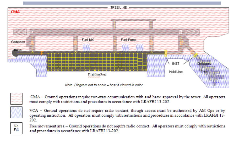
62 LITTLEROCKAFBI13-250 29 APRIL 2010
Figure A3.1. CMA Diagram.
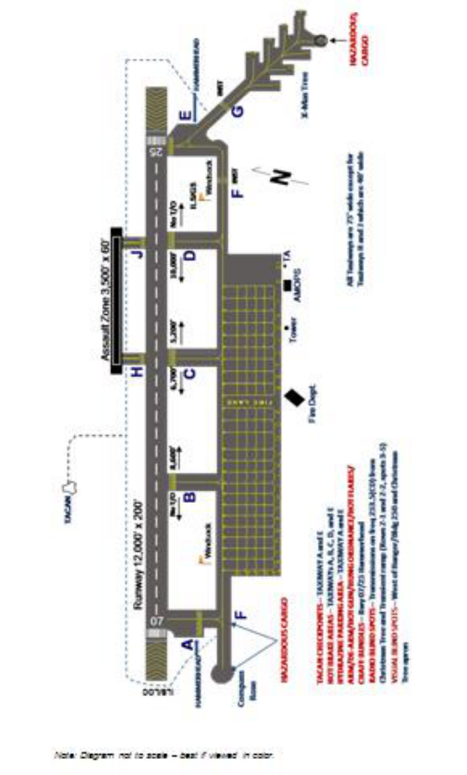
LITTLEROCKAFBI13-250 29 APRIL 2010 63
Attachment 4
AIRFIELD DIAGRAM
Figure A4.1. Airfield Diagram
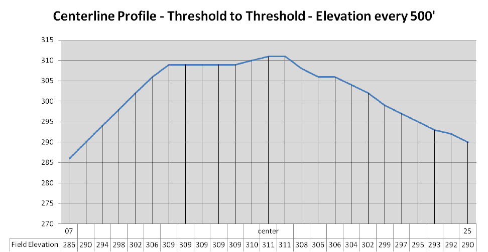
64 LITTLEROCKAFBI13-250 29 APRIL 2010
Figure A4.2. Runway Gradient.
LITTLEROCKAFBI13-250 29 APRIL 2010 65
Attachment 5
ATCALS DOWNTIME REQUEST
A5.1. What is the scope of the work to be done?
A5.2. Why can't work be accomplished during next scheduled maintenance inspection?
A5.3. What is the emergency restoral capability/time?
A5.4. What is the name of the equipment requiring downtime?
A5.5. What is desired window for the downtime?
A5.5.1. Window:
A5.6. Which 19 CS maintenance work center is requesting downtime?
A5.6.1. Office Symbol: SCOA
A5.6.2. Telephone: 7-6829
A5.6.3. POC: TSgt John Hupp, SSgt Jason Smith
A5.7. Will any other missions or equipment be affected during this time?
A5.7.1. Other Missions:
A5.8. (OPTIONAL) If possible, can this work be done outside of the flying window i. e.
A5.8.1. Nights or weekends?
A5.8.2. Nights: Yes.
A5.8.3. Weekends: no.
A5.9. (OPTIONAL) When is the next scheduled maintenance inspection due?
