
FINAL INVESTIGATION REPORT ON
SERIOUS INCIDENT TO AIR INDIA
LTD. AIRBUS A-320 AIRCRAFT VT-ESI
AT COCHIN ON 21.08.2014
COMMITTEE OF INQUIRY VT-ESI
(K Ramachandran)
Air Safety Officer
AAIB
Member
(Raje Bhatnagar)
Assistant Director
AAIB
Member
Foreword
In accordance with Annex 13 to the Convention on International Civil
Aviation Organization (ICAO) and Rule 03 of Aircraft (Investigation of
Accidents and Incidents), Rules 2012, the sole objective of the investigation
of an accident/incident shall be the prevention of accidents/incidents and not
apportion blame or liability.
This document has been prepared based upon the evidences collected during
the investigation, opinion obtained from the experts and laboratory
examination of various components. Consequently, the use of this report for
any purpose other than for the prevention of future accidents/incidents could
lead to erroneous interpretations.

INDEX
CONTENTS
PAGE No.
SYNOPSIS
02
1
FACTUAL INFORMATION
03
1.1
HISTORY OF THE FLIGHT
03
1.2
INJURIES TO PERSONS
04
1.3
DAMAGE TO AIRCRAFT
04
1.4
OTHER DAMAGE
07
1.5
PERSONNEL INFORMATION
07
1.6
AIRCRAFT INFORMATION
10
1.7
METEOROLOGICAL INFORMATION
16
1.8
AIDS TO NAVIGATION
16
1.9
COMMUNICATIONS
16
1.10
AERODROME INFORMATION
16
1.11
FLIGHT RECORDERS
17
1.12
WRECKAGE AND IMPACT INFORMATION
19
1.13
MEDICAL AND PATHOLOGICAL INFORMATION
19
1.14
FIRE
19
1.15
SURVIVAL ASPECTS
19
1.16
TESTS AND RESEARCH
19
1.17
ORGANISATIONAL & MANAGEMENT INFORMATION
34
1.18
ADDITIONAL INFORMATION
34
1.19
USEFUL AND EFFECTIVE TECHNIQUES
34
2
ANALYSIS
34
2.1
SERVICEABILITY OF AIRCRAFT
34
2.2
WEATHER
36
2.3
PILOT FACTOR
36
2.4
CIRCUMSTANCES LEADING TO INCIDENT
37
3
CONCLUSIONS
37
3.1
FINDINGS
37
3.2
PROBABLE CAUSE OF THE INCIDENT
39
4
SAFETY RECOMMENDATIONS
40

1
FINAL INVESTIGATION REPORT ON SERIOUS INCIDENT
TO AIR INDIA LTD. AIRBUS A-320 AIRCRAFT
VT-ESI AT COCHIN ON 21.08.2014
1.
Aircraft
Type
Airbus A-320
Nationality
Indian
Registration
VT-ESI
2.
Owner & Operator
Air India Ltd
3.
Pilot – in –Command
ATPL Holder
Extent of Injuries
None
4.
Co-pilot
ATPL Holder
Extent of Injuries
None
5.
No. of Passengers on board
169 (Pax) + 04 (Cabin Crew)
Extent of Injuries
None
6.
Date & Time of Incident
21.08.2014; 15:36 UTC
7.
Place of incident
Cochin
8.
Last point of Departure
Cochin
9.
Intended landing place
Delhi
10.
Type of Operation
Scheduled Passenger Flight
11.
Phase of operation
Take-off Climb
12.
Type of Incident
In-Flight Shut Down (Uncontained Engine
Failure)
(All timings in the report are in UTC unless otherwise specified)
2
SYNOPSIS
Air India Airbus 320 aircraft VT-ESI flight AI 047 (Cochin - Delhi) was involved in a serious
incident of in-flight shutdown due uncontained failure of engine # 2 on 21-08-2014 at
Cochin. The aircraft was under the command of a pilot an ATPL holder on type & Co-pilot
also an ATPL holder. There were 04 cabin crew and 169 passengers on board the aircraft.
There was no injury to any person on board the aircraft.
The aircraft was operating flight AI047 for Delhi and was cleared for take-off runway 27.
The aircraft took-off at around 1535 UTC from runway 27. Soon after take-off while
climbing the pilot heard a loud bang sound which was followed by engine # 2 fire warning.
The pilot carried out ECAM actions and declared MAY DAY. The pilot informed ATC about
the engine # 2 on fire and requested for priority landing runway 27. The aircraft was then
cleared for landing runway 27. The pilot carried out overweight landing checklist and the
aircraft then landed on runway 27 uneventfully. The aircraft was then parked at bay 11 and
passengers were disembarked normally. Thereafter walk around inspection was carried out
and it was observed that there were metal debris on engine #2 exhaust. The C-duct cowl was
found punctured. There was no injury to any of the occupant on board the aircraft. The fire
was confined to within engine only.
Ministry of Civil Aviation vide order No. AV 15029/118/2015-DG constituted a committee
of inquiry to investigate the cause of the serious incident under Rule 11 (1) of Aircraft
(Investigation of Accidents and Incidents), Rules 2012.
3
1. FACTUAL INFORMATION.
1.1 History of flight
Air India Airbus 320 aircraft VT-ESI was scheduled to operate flight AI 047 from Cochin to
Delhi on 21.08.2014 under the command of pilot, an ATPL holder, qualified on type with
Co-pilot also an ATPL holder, qualified on type. There were 04 cabin crew and 169
passengers on board the aircraft.
Prior to the incident flight the aircraft VT-ESI had operated flight AI 934 from Sharjah to
Cochin. The aircraft landed at Cochin at about 1330 UTC. The flight was uneventful. There
was no snag reported by the pilot after the flight. The aircraft was parked at stand # 4.
Thereafter the aircraft was scheduled to operate flight AI 047 to Delhi. The ATC cleared the
aircraft for take-off runway 27 and informed winds as 140
o
/05 Kts. The aircraft took-off at
1535 UTC from runway 27. After about 01 minute 05 seconds of take-off a loud bang sound
was heard by the cockpit crew which was followed by engine fire warning in cockpit. The co-
pilot informs the PIC about engine # 2 on fire and both the crew then carried out ECAM
actions. On being contacted by ATC for further clearance, the pilot declares MAY DAY due
“engine # 2 fire” and informs that they are maintaining runway heading. The same was
acknowledged by ATC and asked pilot about runway preference. The pilot informed ATC
that they will prefer runway 27 for landing and the same was cleared by the ATC. Meanwhile
cabin crew also informs pilot that the passengers saw fire in engine # 2 and they heard a loud
bang sound from their respective position in cabin. The pilot informs cabin crew to standby
for further instructions. Cockpit crew then carried out approach checklist. The pilot thereafter
informs ATC that they are cancelling MAY DAY call and changing to PAN PAN as there is
no fire now. The pilot then informs cabin crew that they have lost one engine i.e. engine #2
and landing back to Cochin in 05 minutes and advised cabin crew to prepare the cabin for
landing. Cockpit crew then carried out overweight landing checklist and carried out
uneventful overweight landing on runway 27. The ATC then cleared the aircraft for parking
bay 11 via taxiway ‘C’ & ‘B’. The pilot requested ATC for guidance to the bay and someone
to look at the engine for fire. Pilot then requests ATC to inform the company for GPU
(Ground Power Unit) and electrical. After reaching stand, the ATC confirmed with pilot if all
operations are normal for which the pilot replied back as affirm and when asked for further
assistance required, the pilot replied back as negative. The pilot then briefed passengers about
the situation and thereafter confirms with cabin crew that there is no fire. After about 08
4
minutes of the aircraft reaching the bay, the step ladder was attached to aircraft to disembark
the passengers. The passengers were disembarked normally.
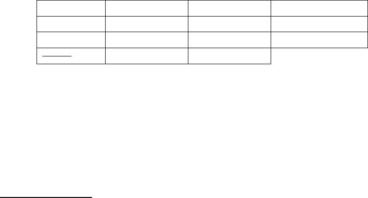
Thereafter walk around inspection was carried out and it was observed that there were metal
debris on engine #2 exhaust. The C-duct cowl was found breached (punctured). There was no
injury to any of the occupant on board the aircraft. The fire was confined to within engine
only.
1.2 Injuries to persons.
Injuries
Crew
Passengers
Others
Fatal
NIL
NIL
NIL
Serious
NIL
NIL
NIL
Minor/None
02+04
169
1.3 Damage to aircraft.
The aircraft damage was confined to engine # 2. No damage was observed in the
surrounding area of the engine (wing lower surface, flap, RH landing gear etc.). Following
main damages were observed on the engine:
External Damages
1. Outboard C Duct
- Outer Barrel found ruptured approximately 12 inches.
- Inner Barrel Burn mark & rupture observed
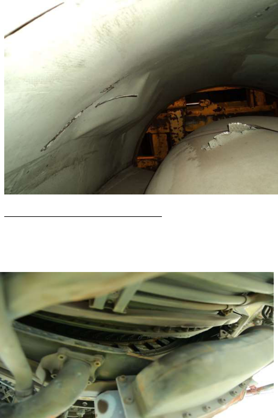
2. Inner C Duct
- Inner Barrel found burnt at 6 O’Clock position.
3. LPT (Low Pressure Turbine) stage 4 blades
- more than 20% of blades found damaged
- Most of the stage 4 NGV’s (Nozzle Guide Vanes) found damaged.
4. Overheating was observed on all the latches.
5
6
Damage to C Ducts
Damages Observed after opening both the C Ducts
5. The turbine cooling air feed tube at 4 O’ Clock position found ruptured.
6. HPT (High Pressure Turbine) case between 1 & 3 O’ Clock position found ruptured
open.
7. HPT case opened up and ruptured from 6 to 9 O’clock position shearing the 27 bolts
on front side and 18 on rear side exposing entire HP turbine area.
The High Pressure Turbine case breached
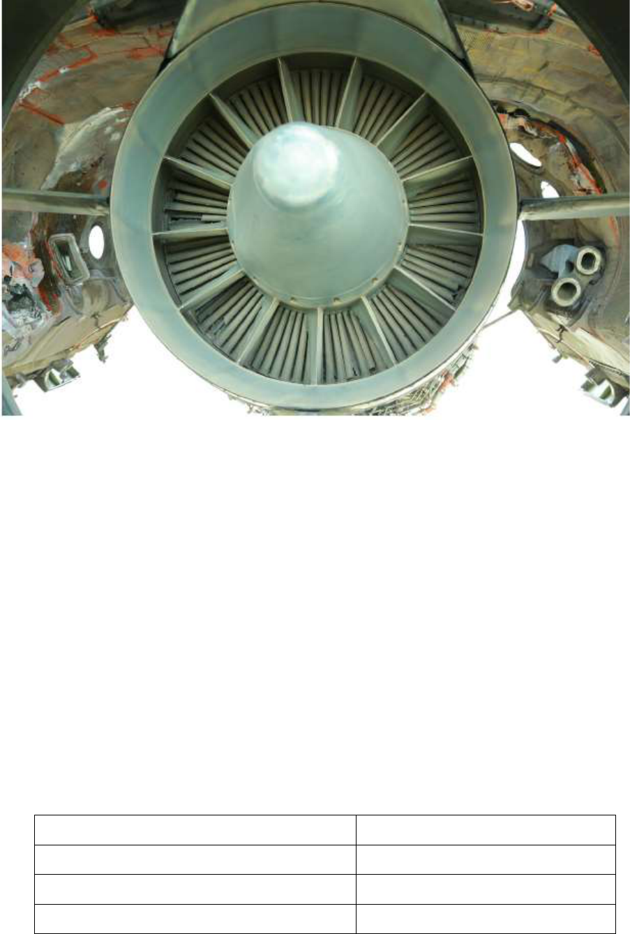
7
Engine Rear View
8. All the turbine blades of stage 1 & 2 and stage 2 NGV’s found missing.
9. Turbine cooling air feed tube at 7 O’clock position found damaged.
10. HPT ACC duct found ruptured.
11. Lot of metal debris found stuck at different locations of the engine.
12. No. 2 shaft seized.
13. The No.1 shaft was found stuck and found difficult to rotate.
14. Fire bottles were found discharged.
1.4 Other damage: Nil
1.5 Personnel information:
1.5.1 Pilot – in – Command:
AGE
48 Years
License
ATPL
Date of License Issue and Valid up to
27/11/13 and 26/11/2015
Category
Aeroplane

8
Class
Multi Engine
Endorsements as PIC
C-152/PA-23,C-90,
A320/A319/A321
Date of Joining Company
06/06/2001
Date of Endorsement as PIC on type
27/02/2006
Instrument Rating
06/11/2013
Date of RTR Issue and Valid up to
25/01/2013 & lifetime validity
Date of FRTOL issue & validity
24/10/2011 & valid upto 23/10/2016
Date of Med. Exam & validity
05/04/2014 & valid upto 04/04/2015
Date of Route Check
01/12/13 to 02/12/13
Date of Last Proficiency Check
25/04/2014
Date of English language Proficiency &
Valid up to
24/01/2011 and Lifetime Validity
Date of last CRM
08/11/2013
Date of Dangerous Goods Awareness
Training
11/11/2013
Date of last Refresher/Simulator
25/11/2013
Simulator Training for Critical Emergencies
25/04/2014
Total flying experience
10000 Hrs. (approx.)
Total Experience on type
7500 Hrs. (approx.)
Total Experience as PIC on type
4500 Hrs. (approx.)
Last flown on type
08/08/2014
Total flying experience during last 01 Year
596:31 Hrs
Total flying experience during last 180 days
380:56 Hrs
Total flying experience during last 90 days
203:05 Hrs
Total flying experience during last 30 days
46:00 Hrs
Total flying experience during last 07 Days
17:40 Hrs
Total flying experience during last 24 Hours
05:15 Hrs

9
1.5.2 Co-Pilot:
AGE
34 years
License
ATPL
Date of License Issue and Valid up to
20/06/2014 & Valid upto 19/06/2016
Category
Aeroplane
Class
Multi Engine
Endorsements as PIC
King Air C-90A/TB-20
Date of Joining Company
04/10/2012
Date of Endorsement as PIC on type
Co-pilot
Instrument Rating
21/09/2014
Date of RTR Issue and Valid up to
30/01/2000 and Lifetime Validity
Date of FRTOL issue & validity
09/06/2011 & Valid upto 08/06/2016
Date of Med. Exam & validity
24/06/2014 & Valid upto 23/06/2015
Date of Route Check
23/09/2013
Date of Last Proficiency Check
03/03/2014
Date of English language Proficiency &
Valid up to
27/11/2013 & Valid upto 26/11/2019
Date of last CRM
06/06/2014
Date of last Monsoon training
June 2014
Date of Dangerous Goods Awareness Training
10/06/2013
Date of last Refresher/Simulator
06/06/2014
Simulator Training for Critical Emergencies
30/03/2014
Total flying experience
3564 Hrs. (approx.)
Total Experience on type
3314 Hrs. (approx.)
Total Experience as PIC on type
Co-Pilot
Last flown on type
13/08/2014
Total flying experience during last 01 Year
748:32 Hrs
Total flying experience during last 180 days
399:53 Hrs
Total flying experience during last 90 days
192:47 Hrs
Total flying experience during last 30 days
69:55 Hrs
Total flying experience during last 07 Days
25:40 Hrs
Total flying experience during last 24 Hours
05:15 Hrs
10
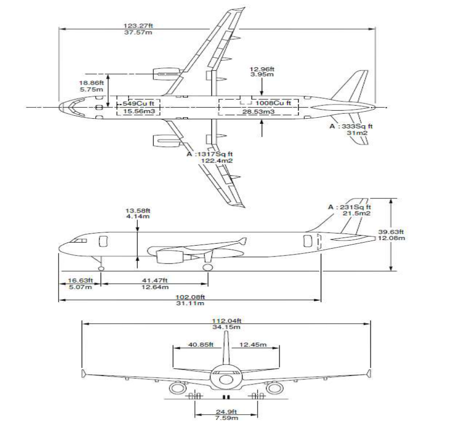
1.6 Aircraft Information
1.6.1 Airbus A320 Information
The Airbus A320 aircraft VT-ESI is a subsonic, medium-range, Civil Transport Aircraft. The
aircraft has two high bypass turbofan engines manufactured by International Aero Engines
AG, USA. The aircraft is designed for operation with two pilots and has passenger seating
capacity of 168.
The aircraft is certified in normal (Passenger) category, for day and night operation under
VFR & IFR. The maximum operating altitude is 39,100 feet and maximum Take-off weight
is 73.5 tonnes. The maximum Landing weight is 64.5 tonnes. The aircraft length is 37.57
meters, wingspan is 34.15 meters and height of this aircraft is 12.08 meters. The distance
between main wheel centers is 7.59 meters.
3 View Diagram of Airbus A 320 aircraft
11
A320 aircraft fuselage is a semi monocoque structure having five main section. The structure
is primarily made of chemically milled skin panels attached with frames and stringers made
of sheet metal. The fuselage has got total 80 No. of frames in which frame No. 1 is forward
pressure bulkhead and frame No. 70 is rear pressure bulkhead. Frame No. 70 to 80 is
unpressurised zone. In general standard frames have a common Z-shaped section made of
formed sheet which provides continuous structural integrity to stringers and skin panels
through sheet metal cleats.
Two wings on each side of the fuselage is attached through a center wing box at the middle of
the fuselage. Wings are joined with the fuselage by means of Cruciform fittings at upper end
and Triform fittings at lower end between center and outer wing box. Wing box are generally
box structure having front and rear spar with number of ribs in between along each outer
wing and the whole things are covered with skin panels. Wings carry the landing gear,
engines and flight control devices. Wing also carries the fuel inside the box cavity.
Primary control surfaces are aileron on wings, elevator on trailing edge (T.E) horizontal
stabilizer and rudder on trailing edge vertical stabilizer. Secondary control surfaces are flaps,
slats and spoilers. All control surfaces are electrically control and hydraulically operated.
Control surfaces are generally having box structure made of Carbon Fiber Reinforced Plastics
(CFRP).
A320 aircraft VT-ESI is fitted with V 2500 – A1 engines manufactured by International Aero
Engines (IAE).
The V 2500 – A1 engine is a dual rotor are variable stator high bypass turbofan engine. The
engine is made of four primary modules.
The fan & LP (Low Pressure) compressor are supported by the fan frame which host forward
engine mount. Five stages LP Turbine drives the forward fan and the four-stage booster
compressor. LP turbine is supported by TRF which host rear engine mount. The high pressure
rotor is made of ten stage HP compressor driven by two stage HP turbine. The annular
combustion chamber is located between HPC & HPT and is equipped with ports for 20 fuel
nozzles and ignitor plugs. The accessory gear box is located at the bottom of the fan case and
is driven by HP rotor through transfer gear box. The fuel pump, oil pump, hydraulic pump
and other accessories are driven by the gear box.

12
1.6.2 General Information
Airbus A320 aircraft VT-ESI (MSN 0486) was manufactured in the year 1994. The aircraft is
registered under the ownership of M/s. AIR INDIA LTD. The Certificate of registration No.
2618/3 under category ‘A’ was issued on 24.02.2011. As on 21.08.2014, the aircraft VT-ESI
had logged 55849: 27 airframe hours & 34460 cycles since new and 4608:28 hours were
logged since last C of A. Airworthiness Review Certificate (ARC) was initially issued on
10.04.2013 and was later extended on 09.04.2014 which was valid up to 10.09.2014.
The aircraft was holding a valid Certificate of Airworthiness Number 2106 issued under
normal category sub-division passenger/ Mail / Goods by DGCA on 10.09.2013 and was
valid till 10.09.2014. The aircraft is holding aero mobile License No. A-014/048-RLO/NR
and was valid on the day of incident. This aircraft was operated under Scheduled Operator’s
permit No. S-09 and is valid till 30.06.2018. Prior to flight the aircraft was holding a valid
Certificate of Flight Release.
The aircraft was last weighed on 16.07.2014 at Delhi, weight schedule was prepared and duly
approved by the office of DAW, Delhi. As per the approved weight schedule the Empty
Weight of the aircraft is 39909.26 kgs. Maximum usable fuel quantity is 18730 kgs.
Maximum payload with full fuel tanks is 10681 kgs. Empty weight CG is 18.76 meters aft of
datum. The next weighing was due on 15.07.2019.
Computerized Load & Trim sheet was made for VT-ESI operating flight AI-047. The Details
of basic weight schedule were as follows:-
Weight
Maximum Permissible (Kg)
Actual Weight (Kg)
Take-off weight
73500
72800
Landing weight
64500
71800
Dry Operating weight for the flight was 44089 Kgs. The c.g of the aircraft was within the
operating limits.
The aircraft and Engines were being maintained under continuous maintenance as per
maintenance programme consisting of calendar period and flying Hours/Cycles based
maintenance approved by O/o DGCA, Delhi dated 06.09.2013. The last Major Inspection ‘4A
check’ inspection was carried out at 55397:46 hours / 34156 cycles on 01.07.2014.

13
Subsequently all lower inspections (Pre-flight checks, Service Checks, Weekly Checks) were
carried out as and when due before the incident.
Engine
Serial No.
Time Since New
(TSN)
Cycle Since New
(CSN)
#1
V0299
42828 hrs
28189
#2
V0118
41505 hrs
27772
The last engine # 2 overhaul was carried out on 31.03.2012 at 33341:37 engine hours. The
engine had logged 8163:23 Hours since last overhaul. The engine # 2 was released from the
shop on 31.03.2012. On 31.03.2012 the engine V0118 was released from shop and installed
on VT-EPH on 03.04.2012.
On 13.09.2012 the engine was removed from VT-EPH and installed onto VT-ESC. On
11.05.2014 the engine was removed from VT-ESC due “repeated high EGT” warning and
was later installed onto VT-ESI (#2 position) on 18.05.2014.
The last fuel microbiological test was done on 24.02.2014 at Delhi by Air India Ltd. During
2A check and the colony count was within acceptable limits.
1.6.3 Lapping Procedure of Bearing Front Seal Seat (Seal Plate)
Long Soak Cleaning: The One Step Alkaline rust remover procedure.
Aqueous Degrease the component.
Soak the component in one of the alkaline rust remover solutions at the applicable
temperature for 30 to 60 minutes.
- The operating temperature range of the solution is 88-93
o
C.
Flush the component with cold water.
- Remove the component from the alkali tank. Use a cold water spray to flush the
alkaline solution from the component. Do this over the tank.
- Pressure spray rinse to remove scale, corrosion, and oxides & put the component
fully in a cold water tank.
- Remove the component from the cold water tank and then use cold water spray to
flush the component again.
Do an inspection of the component to make sure that component is clean.
Flash dry the component with hot water.

14
- Put the component fully in to hot water at a temperature of 66-93
o
C until the
temperature of the component is at the water temperature. Remove the component
from the hot water & flash dry.
Apply the corrosion inhibitor, as necessary to prevent corrosion of component.
Bearing front seal seat- Inspection
Ensure that the component is cleaned before inspection.
Examine component for cracks (Fluorescent Penetrant Inspection) as per Standard
Practices Manual (SPM) Task. Accept or repair if required.
Examine the seal seat for chipped hardface. Accept or repair if required.
Examine the seal seat for hardface that is pitted, scratched or gone. Repair if required.
Accept or repair if required.
Examine the seal seat for nicks, dents, scratches & pits on areas other than the
hardface. Accept or repair if required.
Pilot inside diameter. Accept or repair if required.
Axial dimension. Accept or repair if required.
Measure the thickness of the hardface. Accept or repair if required.
Preserve the part as per SPM Task.
Bearing Front seal seat (Seal plate) - Lap the seat.
The lapping procedure
- The basic lapping equipment is available from one of the sources that follow:
Lapmaste, Supfina, peter Walters of America or their equivalent or their
equivalent. The machine must give the specified surface finish and must be
satisfactory for used with diamond lapping compounds.
- Use a lap plate made of gray cast-iron or Meehanite - GA50. The lap surface
must contain serrations or grooves, with a 90
O
shape.
- The diamond lapping compound must be fully included in the lap. Push the
CoMat 05-118 DIAMOND LAPPING COMPOUND, SLURRY, SPRAY, OR
SUSPENSION, or an equivalent, into the lap: by lapping with a hard steel, or
linde flame plated disk which has a weight of approximately 20 psi. The disk must
be put in the conditioning rings, the same as the part.
- Apply a thin coating of CoMat 10-061 STODDARD SOLVENT to the lap. Run
the lap almost dry, until its surface looks iridescent. The lap must have a matt
15
finish and not look wet, as when too much solvent is used. The lap surface must
be very dark, when fully charged.
- Lap the part at approximately 1 psi (6.9 kPa) and at a rate of 100 to 300 surface
feet a minute (31 to 91 surface meters a minute); as measured at the average
diameter of the area to be lapped.
- It is only necessary to charge the lap again, when the lap time has increased by
more than 50 percent; of that used for a fully charged lap. When the correct load is
applied to the part, the necessary finish will be completed in less than 25 minutes;
if all the operational conditions are satisfactory.
- Examine the lapped surface.
- Clean the parts as per SPM task. Parts put into storage before they are cleaned
must be kept wet with CoMat 10-061 STODDARD SOLVENT so that the lapping
compound will not become dry.
Special procedure used to clean the seal plate and spacer (As per Long Soak Cleaning
SPM Task).
Examine the Seal Seat after Lap repair
- Examine the front seal seat for the surface finish, flatness and the axial dimensions
of the seal seat face.
1.6.4 Oil Consumption History for V0118 Engine.
As mentioned earlier the Engine was installed on 3 different airframes, oil consumption trend
was reviewed from April 2012 to August 2014 which reveled following:
From February 2013 to August 2014 oil consumption indicates upward trend.
Acceptable & stable trend was observed between April 2012 and February 2013.
Maximum consumption observed was 0.258 qt/hr which is less than 0.30 qt/hr
threshold.
No reported evidence of external oil loss (TEC wetting, etc.)
Oil Consumption showed increasing trend but was within limits.

16
1.7 Meteorological information:
The weather at Cochin during the time of incident was:
Time
in
UTC
Wind
Direct-
ion
Speed
(K)
Vis (m)
Weather
Clouds
Temp
(°C)
Dew
Point
(
o
C)
QFE
hPa
QNH
hPa
Trend
1500
100
06
4000
Hz
SCT
450 m
26
24
1006
1007
NOSIG
1530
120
05
4000
Hz
SCT
450 m
25
24
1006
1007
NOSIG
1.8 Aids to navigation:
Cochin airport is equipped with VOR, DME, NDB, and ASDE. PAPI & ILS Cat- II is
installed on Runway 27 & 09.
1.9 Communications:
There was always two way communications between the aircraft and the ATC.
1.10 Aerodrome information.
Cochin Airport is an international airport located in Cochin, Kerala. The IATA location
Identifier code is COK and ICAO location Indicator code is VOCI. The airport is operated by
Cochin International Airport Limited (CIAL). The elevation AMSL of airport is 9.14 m (30
ft). The airport is licensed by DGCA No. AL/Public /005 for both IFR and VFR traffic. The
airport reference code is 4E.
The airport has one runway. The Runway specification is as under:
Orientation: 27/09
Runway Length: 3400 m
Runway Width: 45 m
Runway Shoulder Width: 7.5 m (on both sides)
Strength: PCN 60
Parallel Taxiway: 3400 m
The Airport Reference point is 10°09'13.8''N 072°51'58''E. Runway has marking for
Designation, THR, TDZ, Centreline, Rwy Edge and is lighted for THR, Edge, End, TDZ, and
Centreline. The Airport Rescue and Fire Fighting Services is Category ‘9’ (Nine).
17
1.11 Flight recorders.
The aircraft was fitted with Solid State CVR & DFDR manufactured by L-3
Communications, USA. The CVR & DFDR were removed from the aircraft after the incident
& data from CVR & DFDR were downloaded and analysed.
CVR
A total of last 02:03:23 hrs audio data was available in CVR. Salient observations made from
the CVR tape transcript are given below:
The ATC cleared aircraft for take-off runway 27 and informed winds as 140
o
/05 Kts.
Soon after about 01 minute 05 seconds of take-off a loud bang sound was heard
followed by Engine fire alarm sound in cockpit.
The co-pilot immediately told PIC that “Engine # 2 on fire”.
The PIC then calls for ECAM actions and the same was carried out.
On being contacted by ATC for further clearance, the pilot declares MAY DAY,
informs ATC about “engine # 2 fire” and maintaining runway heading.
The ATC confirms the MAY DAY call and asks pilot for runway preference.
The pilot informed ATC that they will prefer runway 27 for landing.
The cabin crew then informs cockpit crew that they heard a loud bang sound.
The pilot informs cabin crew to standby for further instructions.
ATC again confirm with pilot about reason for MAY DAY and the same was
acknowledged by the pilot.
Cabin crew again informs pilot that the passengers saw fire in engine # 2 and they
heard a loud bang sound from their respective position in cabin.
Cockpit crew then carried out approach checklist.
The pilot then informs ATC they are cancelling MAY DAY call and changing to PAN
PAN as there is no fire.
The pilot then informs cabin crew that they have lost one engine i.e. engine #2 and
landing back to Cochin. He further advised cabin crew if the cabin is ready for
landing.
Cockpit crew then carried out overweight landing checklist.
The aircraft touched down (landed back) after about 13 minutes post engine fire.
The ATC then clears the aircraft for parking bay 11 via taxiway ‘C’ & ‘B’.
18
The pilot requests ATC for guidance to the bay and someone to look at the engine and
confirms it’s the right engine i.e. #2 engine.
Pilot then requests ATC to inform to the company for GPU and electrical.
ATC confirms for all operations normal, and ask for any further assistance for which
the pilot replied back as negative.
The pilot then briefs passengers about the situation and thereafter confirms with cabin
crew that there is no fire.
After about 08 minutes of the aircraft reaching the bay, the step ladder was attached
to aircraft to disembark the passengers.
Thereafter the pilot was heard discussing about engine C-duct breach with one of the
ground personal.
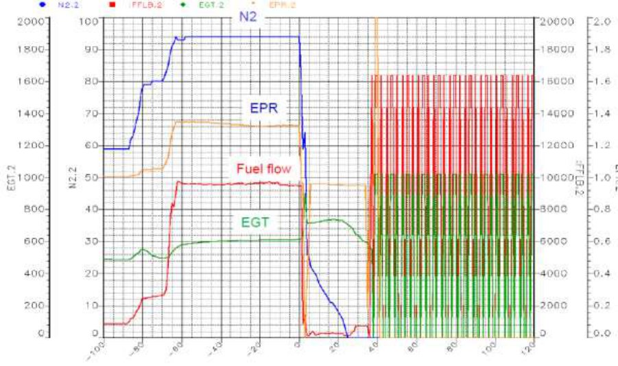
DFDR analysis was carried out and following observations were made:-
The aircraft took-off at 15:35:49 UTC heading 270.
After about 65 seconds of take-off i.e. 15:36:54 UTC, the Engine # 2 N2 decreases
from 93 to 78, probably the time of incident.
In another 30 seconds the Engine # 2 TLA (Thrust Lever Angle) was changed from
34 to 0.
Engine # 2 parameters vs time with the time of incident taken at t=o.
19
Engine #2 EGT over limit sustained for approximately 30 seconds ranging from
637
o
C to a maximum of 735
o
C.
The engine # 2 fire warning sustained for about 131 seconds.
High engine # 2 N2 vibrations for 04 seconds.
1.12 Wreckage and impact information.
The aircraft sustained damages to the core engine and the engine C-duct.
1.13 Medical and pathological Information:
Both the Cockpit crew had undergone pre-flight medicals / Breath analyzer test and were
found to be negative.
1.14 Fire:
The fire was confined to engine # 2 only.
1.15 Survival aspects:
The incident was survivable.
1.16 Tests and research:
1.16.1 Engine Strip Examination
The involved engine ESN V0118 was brought to Delhi and strip examined at JEOC, Air
India by NTSB (Technical experts from IAE) in the presence of Committee of Inquiry and
representatives from Airbus Industries. The engine was stripped and some of the damaged
engine parts were transported to NTSB (IAE/ Prat & Whitney) for further detailed
examination.
Observations made during the strip examination of the damaged engine are as follows:
General:
All location references are aft looking forward (ALF) and the numbering convention is by
analog clock position.
20
The engine data identified the engine as V0118. The low pressure compressor (LPC) fan case
module was verified as serial number 320118. The electronic engine control (EEC) was
verified as serial number 25/29/31/32. The high pressure turbine (HPT) module was verified
as serial number 450087. The low pressure turbine (LPT) module serial number was unable
to be verified as it was illegible due to significant oxidation on the data plate.
The engine was found with the Common Nozzle Assembly (CNA) attached. There were
indication of fire damage at the 12’O clock position on the CNA, and the damage extended
axially from where the CNA attaches to the engine, to the aft most point on the CNA, and on
the external surface at 12’O clock position where the CNA mates with the aft –most portion
of the engine pylon. The internal damage consisted of a charred and sooted surface measuring
approximately 12 inches by 12 inches and the external surface was lightly covered in black
soot and discoloration in an area measuring 12 inches wide by 16 inches long.
Sooting was present at the 12’O clock location on the LPT case, and on the main turbine case
cooling (TCC) supply line.
All accessory components were found still installed on the engine.
There was oil present in the main engine oil tank, but a quantity was not measured. The
integrated drive generator (IDG) oil level was found to be in the green band of the sight glass
indicator.
All engine mounts were found still installed and intact with no obvious damage observed.
The pins located on the aft mount on the LPT were difficult to remove, had some oxidation
present and exhibited radial scoring along their load bearing surface upon removal.
Fan / Low Pressure Compressor Module:
The fan and spinner were intact with 22 blades present and numbered. The fan was able to
rotate freely, and also rotated the LPT. Fan blade#1 had a cropped area at the leading edge of
the tip. Fan blade#21 had a cropped area at the tailing edge of the tip. The fan rub strip
located on the inner diameter (I.D.) of the fan case in the plane of fan rotation had a rub 360
o
around the circumferences, with heavier rub marks at the 2’O clock and 10’O clock locations.
All external hardware was present on the outside of the fan case with no damage noted. The
inlet guide vanes for the low pressure compressor (LPC) were intact and present with no
damage noted. The fan exit guide vanes (FEGV) were intact and present with no damage
noted.
21
The forward bearing compartment (FBC) which is comprised of the #1, #2 and #3 bearing
compartments and associated hardware was not examined.
High Pressure Compressor Module:
The high pressure compressor (HPC) was intact with no damage noted. Powder-like residue
from the fire extinguisher agent, which was coloured white, covered nearly the entire HPC
assembly the Variable Guide Vanes (VGV) on the HPC were positioned in a near fully open
position. All visible VSV hardware was intact and undamaged. All the VSV hardware was
intact and undamaged. The I.D. of the HPC shaft showed evidence of a rub from contact with
the LPT shaft. The area of the rub covered approximately 180 degrees of the shaft I.D. and
was 7 inches long axially towards the front of the engine.
The HPC was examined by borescope and showed indications of a rub on the 3rd and 4th
stages. A dust- like material was present throughout this location in the HPC. This dust-like
material resembled liberated abraidable coating material from the HPC casing. There was no
obvious wetting towards or presence of fluids in, on, or around the 3rd and 4th HPC stages.
Diffuser Module:
The diffuser case was intact with no external damage noted. Powder-like residue from the fire
extinguishing agent, which was coloured white, covered the external surface and hardware of
the diffuser case in random locations. The diffuser case was examined via borescope.
Domestic object debris (DOD) was found inside the diffuser case, within the combustor liners
at the 2’O clock position. The 1st stage Nozzle Guide Vanes (NGV) were eroded at both the
leading and trailing edges, with impact damage at location at 10’O clock and 2’O clock,
DOD was found speared and lodged through the 1st stage NGV’s in a forward direction, at
the 3’O clock position.
Coked oil was found on the HPC shaft at the interface of the carbon seal and the shaft
circumference on the aft side of the #4 bearing compartment.
High pressure Turbine Module:
The HPT Module had four locations where the case was damaged in a manner consistent with
material having penetrated through the case. These four locations are referred to as un-
containment location. Two un-containment locations were at 11’O clock in the plane of the
2nd stage NGVs. Each of these two holes were approximately 2 inches long in the
22
circumferential direction and 1inch long in axial direction. Another un-containment location
consisted of the HPT case being torn open aft of M-flange and forward of N-flange from
approximately the 9’O clock to the 6’O clock position. M-flange was separated at the 6’O
clock position, and N-flange was separated at the 7’O clock position. Of the 100 nuts and
bolts that should be present at M-flange, 28 were missing. Of the 100 nuts and bolts that
should be present at N-flange, 20 were missing.
The tear in the HPT case originated at approximately 9’O clock position, just forward of N-
flange, and extended circumferentially towards approximately 6’O clock position. The widest
point of the tear was approximately 2 inches. At 6’O clock position the tear was nearly the
entire width of the HPT case, approximately 6 inches the tear extended past the fractured M-
flange location at 6 inches, and transitioned into an approximately 1 inch wide elongated and
non-uniform hole, which terminated at approximately 5’O clock position, the remaining un-
containment location was present between1’O clock and 3’O clock. It was an elongated, non-
uniform hole that was 2 inch wide at its widest location and 0.5 inches wide at its narrowest
width axially.
A quantity of ten 2
nd
stage Blade Outer Air Seals (BOAS) were found intact and in place and
showed impact damage at the 1’O clock to 4’O clock positions. The rest of the BOAS were
unable to be identified or located at disassembly.
A quantity of five 2nd stage outer diameter (O.D.) vane platforms, were in place and
significantly damaged with approximately 90% of total material missing. A quantity of two
2nd stage O.D. vane platforms were dislodged and located against the case between 1’O
clock and 3’O clock position, just forward of the 2nd stage BOAS, which were in place.
A quantity of ten 1st stage BOAS supports were found intact and in place beginning at the
12’O clock position and progressing counter-clockwise (CCW) towards the 6’O clock
location. The BOAS support flange located just forward of the O.D. case rail was not in place
with some material remaining. It was bent forward from the 3’O clock to 9’O clock position.
A quantity of 33 BOAS were liberated from the engine. One BOAS was recovered in a box
of debris which arrived with the engine.
The HPT nut was removed by normal means. The indicated breakaway torque of the HPT nut
was approximately 1750 ft-lbs.
23
A section of the HPT 1st stage seal was cut at 6’O clock and 8’O clock position in order to
permit further hardware removal.
The 1st stage blades were fractured near or at the platform, while the 2nd stage blades
retained 25% of their original length nearly uniformly around 360
o
of the circumference of
the rotor. The 2nd stage blades had a fracture surface similar to the profile of the under barrel
of the 2nd stage seal. The remnants of the 1st stage HPT blades were found retained in their
disk attachment location. The 2nd stage HPT blades around 20 in number were displaced
forward by approximately ¼ inch. The 1st stage near HPT air-seal were all damaged. Around
13 seals were liberated from their installed locations. The disk attachment teeth located on the
aft side of the 1st stage disk were sheared off in the region of the missing seals. The 2nd stage
NGV’s were liberated from their installed locations. The 2nd stage HPT retention tabs were
intact and in place with no damage noted.
The aft side of the 1st stage HP disk showed impact marks and scoring. All 12 air metering
plugs were intact and in place with no damaged noted. The front side of the 2nd stage HPT
disk showed impact marks and scoring, consistent with the diameter of the inner bore of the
2nd stage seal.
The HPT 2nd stage air-seal assembly was damaged and detached from its mounting location.
The inner bore and bore to web transition fillet of the 2nd stage seal was fully intact and was
found resting on the bores of the 1st stage disks. The 2nd stage air-seal assembly was
fractured on the O.D. of the web. There were two regions where the fracture extended
inwards towards the bore. These fractures terminated at approximately the bore to web
transition fillet, and were approximately 120
o
apart.
Four pieces of the outer barrel of the 2nd stage air-seal assembly were recovered. The largest
piece measured approximately 38 inches in length and was found lodged inside the
combustor between the 11’O clock and 5’O clock position on the 4th and 5th rows of the
outer combustor liner segments. The next largest piece measured approximately 16 inches in
length and was found lodged in the combustor assembly from 1’O clock and 3’O clock and
laying against the HPT case between the 1st and 2nd HPT rotors. The largest piece measured
approximately 14 inches in length and was found at the 3’O clock position protruding
outward through the 1st stage NGV’s and aft towards N-flange. The final and smallest piece
was approximately 2 inches by 2 inches and was found lodged between two 1st stage NGVs
at the 9’O clock position.
24
Coked oil was present at the forward inner snap diameter location of the 1st stage HPT, 360
o
around the circumference. Thickness or width could not be determined.
Low Pressure turbine Module / Turbine Exhaust Case:
The LPT module was intact and visible rotating hardware was found damaged. There were no
uncontained penetrations visible through the LPT case. The LPT shaft showed signs of
contact approximately 4 inches long and its widest point and was in the plane of the 2nd stage
HPT rotor. Just forward of P flange on the LPT and extended 360 degrees around the
circumference of the shaft at this location. At a location approximately 14 inches forward
from where the LPT shaft is necked to a larger diameter, a contact mark approximately 1 inch
long and ½ inch wide at its largest point was present.
All 3rd stage LPT vanes exhibited impact damage, with vane trailing edges most significantly
damaged at 3’O clock location. Liberated HPT hardware was also found lodged at this
location. At 12’O clock, two LPT 3rd stage inner transition ducts were found dislodged from
their intended position. Additional HPT hardware was found loosely lodged in the 3rd stage
LPT vanes and in the case, predominantly at the 6’O clock location.
The 7th stage LPT rotor blades were all present, but all also exhibited impact damage in
varying forms. The damage varied from a blade which had approximately 30% of its span
missing to blades which had trailing edge damage only and to blades which were missing
their outer shroud. The 7th stage blade outer air-seal was distressed, with minimal
honeycomb seal material remaining and indication of machining damage, in the form of a
distinct groove which extended 360
o
around the circumference of the inner barrel. The 7th
stage stator vanes in the LPT were able to be partially viewed. Missing material in varying
dimensions and locations was observed on every vane.
The #5 bearing compartment and associated components located in the LPT module showed
no signs of distress. The #4 weep tube port, which is located at approximately between 5’O
clock & 6’O clock position on the turbine exhaust showed no signs of oil leakage. The
exhaust plug which interfaces with the I.D. of the TEC showed no signs of damage.
Externals:
The turbine cooling air (TCA) feed tube which interfaces with the HPT case at 4’O clock was
found 75% severed around its diameter and showed signs of impact damage. The majority of
the damage was located on the outboard portion of the tube, forward of m-flange. The TCA
25
tube which interfaces with the HPT case at 8’O clock had the outboard portion of the tube
which bends inward toward the HPT case dented. The dent was approximately 3 inches long
along the surface of the tube and 1 inch wide at the widest point. The depth of the dent was
approximately 25% of the tube diameter. The air cooled air cooler (ACAC) located at 7’O
clock between M and N-flange showed signs in the form of dents from impact damage on the
inboard side of the assembly which faces the HPT case.
The turbine case cooling (TCC) tubes located at the un-containment locations on the HPT
case had signs on impact damage and were crushed or bent. The forward most TCC tube on
the HPT at 3’O clock had a piece of metal approximately 4 inches long by 25 inches wide at
the widest point speared through the centre of the tube body. Tubes which were located
between 5’O clock and 7’O clock in the plane of un-containment on the HPT case had
peppering and slight impact damage.
The remainder of externals located other than in the planes of un-containment on the HPT
case elsewhere on the engine were found installed and impact with no obvious damage
observed.
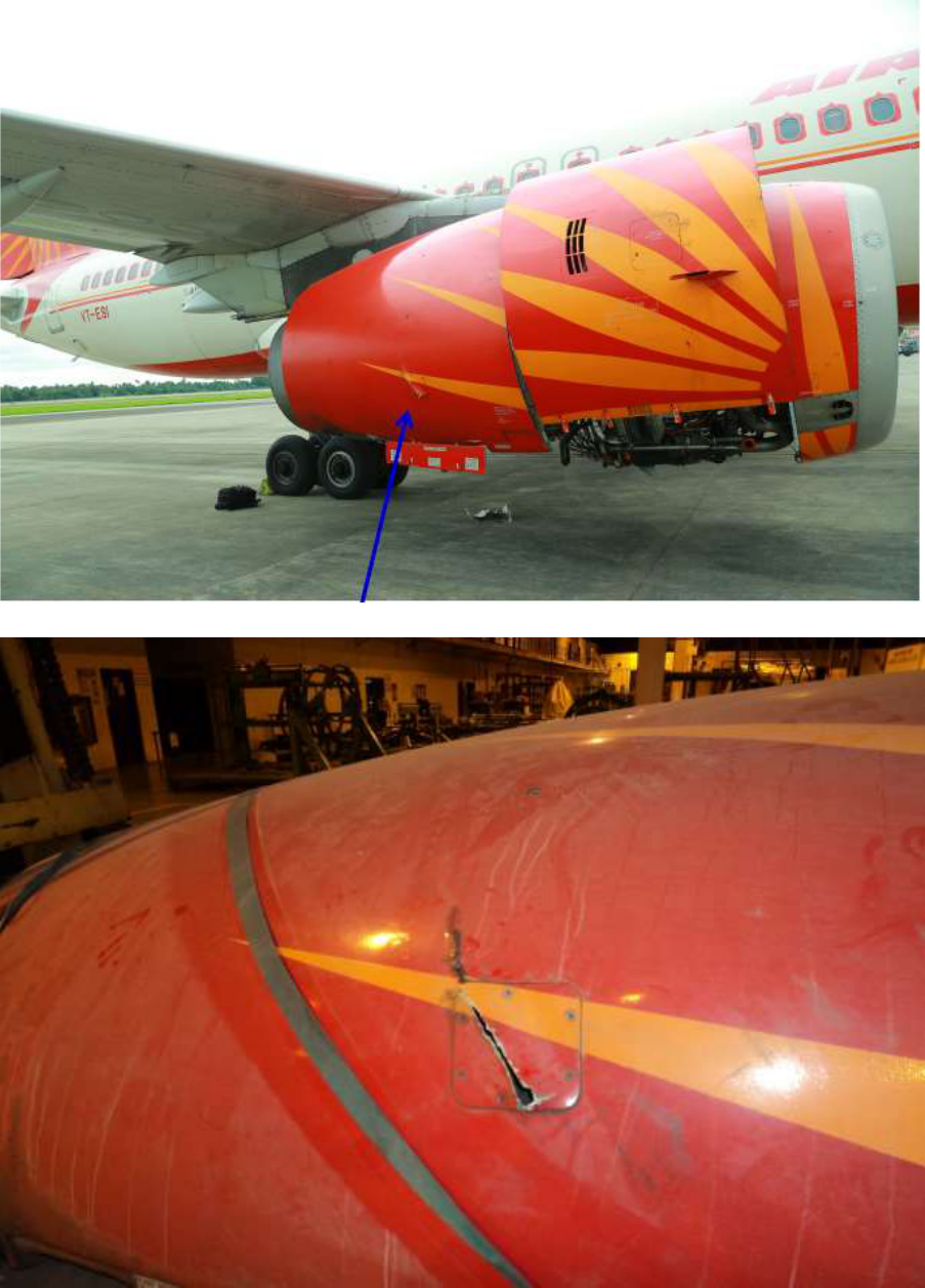
Nacelle:
The inboard and outboard nacelle assemblies installed at the time of the event were available
for review. All nacelle and access panel latches were in place and appeared undamaged. The
outboard nacelle had damage at 5’O clock position in the form of a tear which is
approximately 14 inches in length and 2 inches wide at the widest point. The tear originates 6
inches above an access panel at this location, and continues down at the approximate 45
o
angle relative to an installed position, and terminates at the forward most bottom edge of the
access panel. The inner diameter of the inner barrel of the outboard nacelle had impact
damage at 3’O clock position and evidence of thermal damage and sooting between 1’O
clock and 3’O clock. the inner diameter of the outer barrel of the outboard nacelle had impact
damage at 3’O clock and a piece of DOD of an undeterminable dimension, penetrated into
this location. The wall at this location was bulged inward towards the engine centreline just
aft of this location. Accurate dimensions could not be determined.
The inboard nacelle outer surface which faces towards the airframe was intact and showed no
areas of un-containment. The inner diameter of the inner barrel of the inboard nacelle was
thermally damaged and material missing. The abatable coating was damaged and honeycomb
material crumbled when touched. Accurate dimensions could not be determined. The outer

26
diameter of the inner barrel had two un-containment locations at approximately the 6’O clock
location. Accurate dimensions could not be determined.
1.16.2 Seal Plate Lapping Process Review
After the strip examination of the involved engine S/N V0118 at JEOC, Air India, some of
the damaged engine parts were sent to NTSB (IAE/ Prat & Whitney), USA for detailed
metallurgical testing. The damaged engine parts like fractured HPT 1-2 seal and other
damaged parts were analysed for probable root cause of engine fire/failure. No. 4 seal plate
of engine # 2 (V0118) was analysed and it was observed that the weep grooves and holes of
the seal plate were mostly blocked with lapping debris. In order to confirm the same, on site,
lapping process review was carried out at JEOC overhaul shop by IAC Personnel.
Observations
A review of the shop processing procedures and records for a typical seal plate was
conducted. To accomplish this, a used seal plate was provided by IAE. The seal plate part
number was 2A3432, which is representative of a front seal plate used in the #4 compartment
in the V2500 engine. No serial number or other identification markings were present on this
seal plate. It was observed that the JEOC seal plate lapping process matches with the IAE
Engine Manual (EM) and Standard Practices Manual (SPM). The process sheet follower was
properly signed off as per standard JEOC procedures. The JEOC process sheets utilized
during this review were provided.
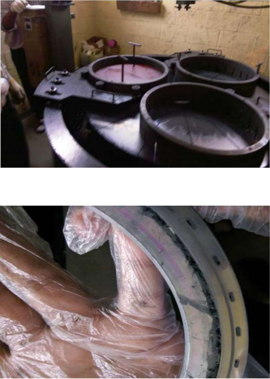
The entire lapping process was observed from beginning to end as per the JEOC process
sheets. Before lapping, the IAE supplied seal plate used in the review was processed through
the pre-lapping cleaning procedure. After this initial cleaning process, carbon and staining
were removed but the grooves had black residue remaining. See image #1.
After cleaning and prior to the lapping process, the subject seal seat was dimensionally and
visually inspected. Instead of performing a Magnetic Particle Inspection (MPI), JEOC
performs a Fluorescent Penetrant Inspection (FPI) via a waiver which was not documented,
granted by IAE. FPI was not carried out in the interest of time as this was a demonstration
article and was not germane to the intent of this process review. The seal seat was examined
for a chipped hard face condition, deep scratches or pits, and blocked oil slots.
The first step as per the process before physical lapping was to clean the table. This involved
wetting the table with a locally available product consistent with the EM recommendation,
27
and then wiping the lapping table surface with a cloth while rotating the table. The intent of
cleaning procedure is to ensure that all lapping residue from previous operations is removed.
See image #2.
Debris was found in the sump or area underneath and beside the lapping table surface where
lapping medium collects as a result of the process. A sample was obtained for analysis by
IAE in order to provide some history of past lapping constituents.
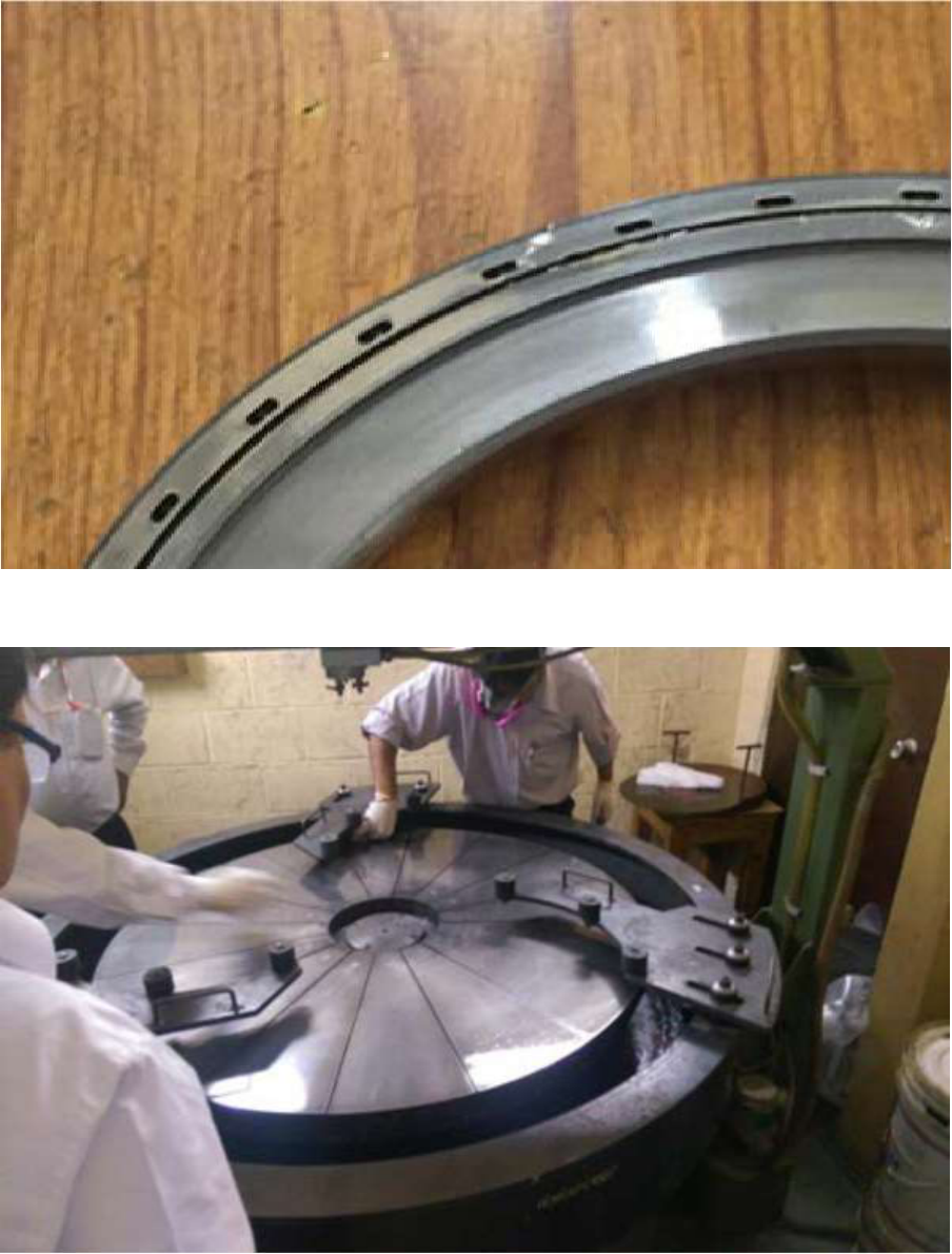
When the table cleaning process was completed, the lapping tooling was installed and
diamond lapping paste applied to the table. See image #3. The machine was run for 5 minutes
to distribute the diamond paste as per normal JEOC practice.
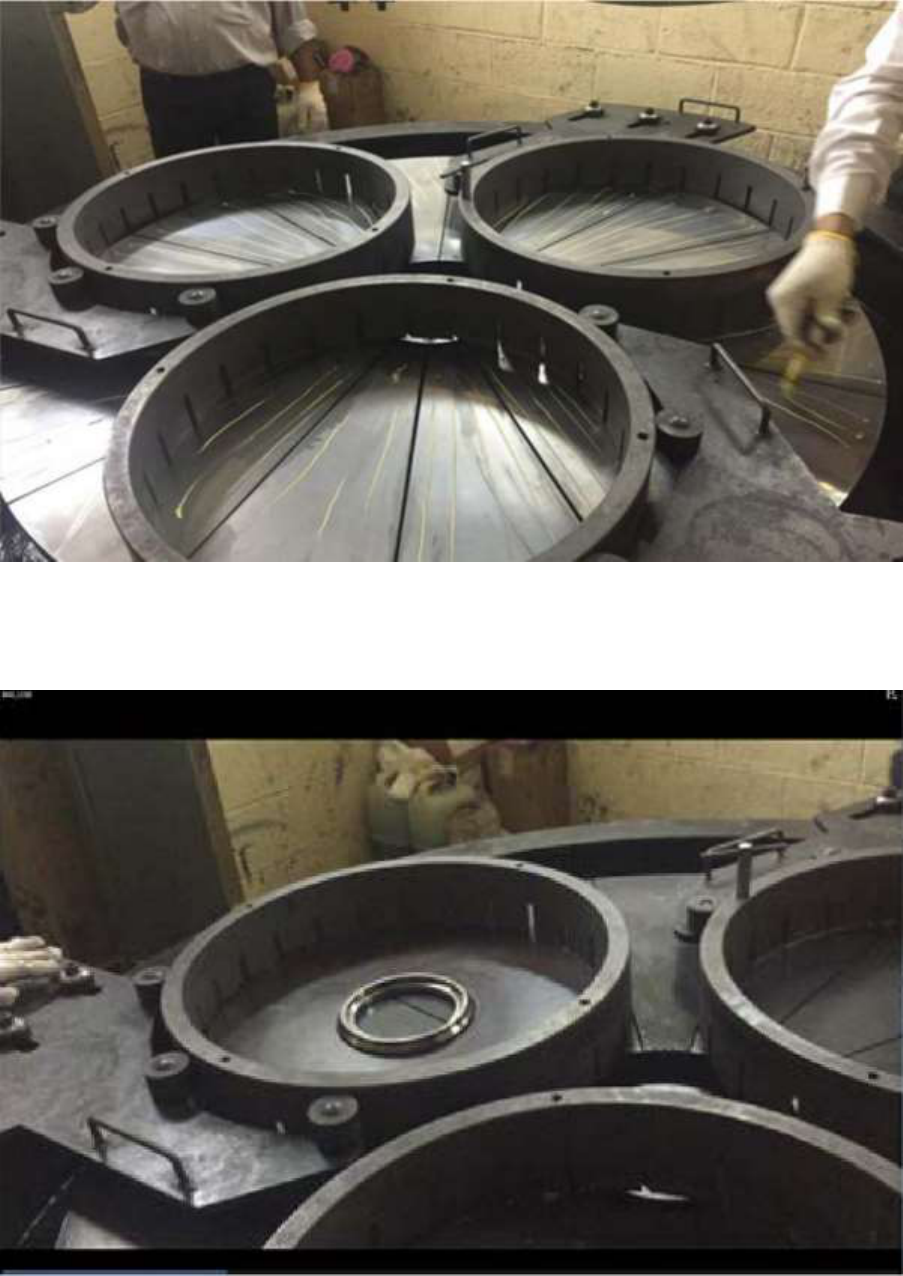
After the diamond paste was distributed, the subject seal seat was placed on table. See image
#4. The positioning tooling was then installed and a weight consisting of a 28kg steel disc
was placed on top of the seat. See image #5. The seat was lapped for 10 minutes. Additional
solvent was added in small quantities during the process when the table appeared too dry to
the operator performing the process.
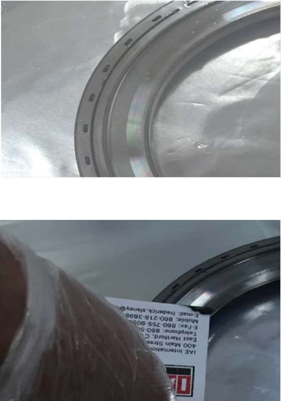
After lapping, the seal plate was removed from the machine. There was lapping residue
deposited in the lubrication slots and holes present in the seal plate as depicted in image #6.
The seat was run through the cleaning process and coated with preservation oil as per the
EM. Subsequently, the seal plate was presented to IAE as being in a clean condition and
ready for use in an engine as per the JEOC process sheets and the IAE EM. See image #7.
Visual inspection showed that lapping residue had not been completely removed from
external surfaces. Visual inspection of the slots and lubrication holes was difficult and could
not be performed.
A business card of one of the IAE personnel present was run along a slot of the seal plate,
allowing for a collection of lapping debris on the card. Debris was raised out of the slot
during this procedure. A sample of this debris was retained, analyzed, and compared to the
debris acquired from the V0118 seal plates. See images #8 & #9.
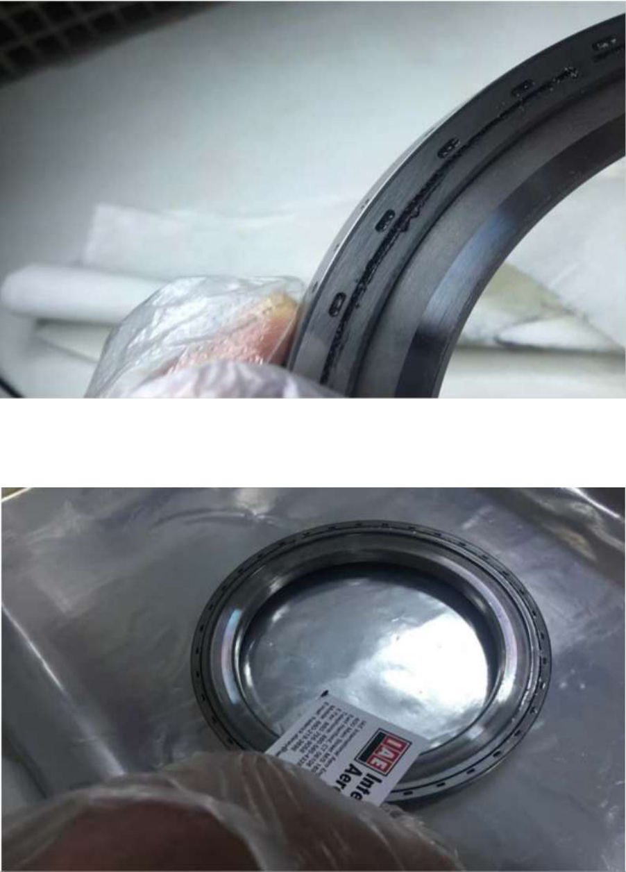
After this observation was made, JEOC personnel then physically removed as much material
as possible with plastic picks and ran the part through the cleaning cycle a second time.
Another business card was inserted and debris was present again but to a lesser degree than
the original attempt to check for debris. See image #10.
28
Image #1 – Demonstration seal plate after cleaning and before lapping.
Image #2 - Cleaning the Table with Hicrolap solvent prior to lapping.
29
Image #3 - Tooling Installed and Diamond Lapping Paste Applied (yellow streaks).
Image #4 - Placement of seal plate for lapping.
30
Image #5 – Seal plate installed in lapping machine with 28kg weight installed.
Image #6 – Post lapping condition of the demonstration seal plate.
31
Image #7 – Post cleaning condition of the demonstration seal plate.
Image #8 – Lapping debris removed from demonstration seal plate slot.
32
Image #9 – Debris removed from demonstration seal plate groove after process complete.
Image #10 – Debris removed from demonstration seal plate after second cleaning cycle.
33
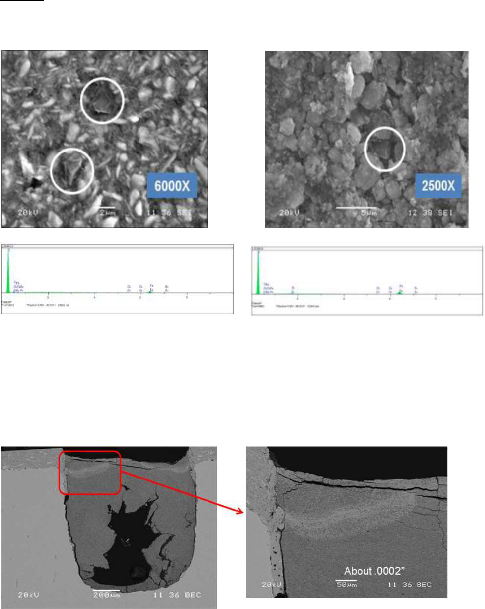
Findings
Diamond particles found in anti-weep grooves of Both V0118 event seal plates &
JEOC Demonstration seal plate.
Debris from V0118 seal plate Debris from JEOC Demonstration Seal plate
Chemistry and aspect ratio of metallic Debris & Diamond particles matches OEM
lapping Debris.
Diamond particles not found in environmental debris
Barium found in anti-weep grooves of both V0118 event seal plates & JEOC
demonstration seal plates; source identified as preservation fluid (AeroShell Fluid 12).
Cross section of V0118 seal plate Anti-weep Groove
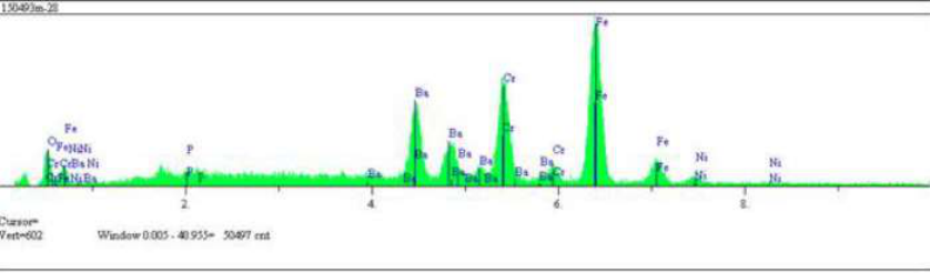
34
Barium was not found outside of V0118 Anti-Weep Groove, Therefore it was not
environmental.
1.17 Organizational and management information:
Air India Limited is a Scheduled Airlines and operates a fleet of Airbus and Boeing aircraft.
The airline was issued Air Operator’s Permit (AOP) No. S-9 in Category “Passenger and
Cargo” by DGCA and was valid at the time of incident. The Airline IATA Code is “AI”,
ICAO code “AIC” and call sign “Air India”. The airline operates a fleet of 113 aircraft
includes 24 Airbus A319-100 aircraft, 28 Airbus A320-200 aircraft, 20 Airbus A321-200
aircraft , 05 Boeing 747-400 aircraft, 15 Boeing 777 aircraft and 21 Boeing 787 aircraft. Air
India is having 02 Subsidiaries as Air India Express & Air India Regional which have
separate permit. The airline operates at 84 destinations (48 Domestic + 36 international) and
having approx. 28000 employees. The airline has headquarter in New Delhi. Its primary hub
is at Indira Gandhi International Airport, New Delhi, and secondary hub at Chhatrapati
Shivaji International Airport, Mumbai.
1.18 Additional information: Nil
1.19 Useful or effective investigation techniques: NIL
2. ANALYSIS
2.1 SERVICEABILITY OF THE AIRCRAFT
2.1.1 Airbus A320 aircraft VT-ESI (MSN 0486) was manufactured in the year 1994. The
Certificate of registration was valid at the time of incident. As on 21.08.2014 the aircraft
had logged 55849: 27 airframe hours and 34460 cycles since new and 4608:28 hours were
logged since last C of A. Airworthiness Review Certificate (ARC) was valid up to
10.09.2014.

35
The aircraft was holding a valid Certificate of Airworthiness. The aircraft was holding
valid aero mobile License. This aircraft was operated under Scheduled Operator’s permit
No. S-09 valid till 30.06.2018. Prior to incident fight the aircraft was holding a valid
Certificate of Flight Release.
The aircraft and Engines were being maintained under continuous maintenance as per
maintenance program consisting of calendar period based maintenance and flying
Hours/Cycles based maintenance as per maintenance program approved by O/o DAW,
Delhi. The last Major Inspection ‘4A check’ was carried out at 55397:46 hours / 34156
cycles on 01.07.2014. Subsequently all lower inspections (Pre-flight checks, Service
Checks, Weekly Checks) were carried out as and when due before the incident.
Engine
Serial No.
TSN
CSN
#1
V0299
42828 hrs
28189
#2
V0118
41505 hrs
27772
The last engine # 2 overhaul was carried out on 31.03.2012 at 33341:37 engine hours. The
engine had logged 8163:23 Hours since last overhaul. On 11.05.2014 the engine was
removed from VT-ESC due “repeated high EGT” warning and was later installed onto
VT-ESI (#2 position) on 18.05.2014.
The last fuel microbiological test was done on 24.02.2014 and the colony count was
within acceptable limits.
The load and trim sheet was prepared before flight and c.g. of the aircraft was within the
operating limits. There was no snag reported on the aircraft prior to the incident flight.
2.1.2 After the strip examination of the involved engine S/N V0118 at JEOC, Air India, some of
the damaged engine parts were sent to NTSB (IAE/ Prat & Whitney), USA for detailed
metallurgical testing. The damaged engine parts like fractured HPT 1-2 seal and other
damaged parts were analysed for probable root cause of engine fire/failure.
No. 4 seal plate of engine # 2 (V0118) was analysed and it was observed that the weep
grooves and holes of the seal plate were mostly blocked with lapping debris. In order to
confirm the same, on site, lapping process review was carried out at IAC overhaul shop by
IAC Personnel. IAC personnel performed lapping process demo using IAE provided
36
V2500, #4 seal plate. After lapping, cleaning and preservation, it was observed that, seal
plate weep grooves contained residual lapping debris or “slurry”. The slurry was analysed
and was found to be matching with V0118 # 4 seal plate debris.
Both samples contained:
Diamond particles- consistent with lapping paste.
Barium- consistent with Aero-Shell 12, used for preservation.
Iron particle size- consistent with lapping table.
The Anti weep circuit prevents the oil from escaping the compartment during sub idle
conditions. V0118’s # 4 seal plate weep grooves and holes which were mostly blocked
with lapping debris, allowed the oil release from #4 bearing compartment at the sub idle
condition during start and shutdown.
The #4 seal plate lapping was carried out during the #2 engine overhaul and inadequate cleaning and
inspection of Seal Plate after lapping resulted in most of the seal plate groove and holes
getting blocked with lapping debris. This allowed the oil to escape # 4 compartment at engine
sub-idle and getting ignited at increased engine power.
In view of the above it is inferred that serviceability of the aircraft engine is a factor to the
incident.
2.2 WEATHER:
At the time 1530 UTC, the visibility was reported to be 4000 meters with winds 120/05 kts,
temp 25°, Dew point 24 QFE 1006 hPa, QNH 1007 and clouds not significant.
In view of the above the weather at the time of incident was fine and is not a contributory
factor to the incident.
2.3 PILOT FACTOR
Both the cockpit crew were qualified to operate the subject flight. The PIC and the co-pilot
both were holding a valid ATPL license and were qualified on type. Both the crew were
current in all the trainings and ratings as per the requirements. The pilot had total flying
experience of about 10,000 hours with approximately7500 hours on type and about 4500
hours as PIC on type. The co-pilot had total flying experience of about 3564 hours and
approximately 3314 hours on type as P2.
37
The ATC cleared the aircraft for take-off runway 27. The pilot carried out pre take-off
checklist and the aircraft took-off at around 1535 UTC from runway 27. After about 01
minute 05 seconds of take-off a loud bang sound was heard by the cockpit crew which was
followed by engine fire warning in cockpit. The co-pilot immediately informed the PIC about
engine # 2 on fire and as per procedure they carried out ECAM actions. The pilot declared
MAY DAY and informed ATC about “engine # 2 fire”. The pilot then informed ATC that
they will prefer runway 27 for landing. Both the cockpit crew then carried out approach
checklist. The MAY DAY call was cancelled by PIC and was replaced by PAN PAN as the
fire warning went off afterwards. The pilot then informs cabin crew that they have lost one
engine i.e. engine #2 and landing back to Cochin. The Cockpit crew then carried out
overweight landing checklist and carried out uneventful overweight landing on runway 27.
The pilot requested ATC for guidance to the bay and someone to look at the engine for fire.
Pilot then requests ATC to inform the company for GPU and electrical.. After reaching stand,
the pilot briefed the passengers about the situation.
2.4 CIRCUMSTANCES LEADING TO THE INCIDENT
Engine # 2 was overhauled at engine overhaul shop. During the overhaul process lapping of
the No. 4 bearing seal was carried out. During the process, the anti-weep grooves which prevent
the oil from escaping the compartment during sub idle conditions were not adequately
cleaned and inspected which resulted into most of the grooves blocked with lapping debris.
This allowed the oil to escape the No. 4 bearing compartment and migrate to the HPT (High
Pressure Turbine) at the sub idle condition during start and shutdown. The oil migration to
the HPT resulted into the oil ignition in the HPT during the power ON condition. This might
have resulted into formation of crack in the HPT 2nd stage air-seal at high temperatures. The
crack may have propagated and eventually developed into low cycle fatigue fracture of 2nd
stage air-seal located in the HPT module and subsequently to engine fire. The damaged parts
of air seal at high temperatures then damaged the HPT blades which subsequently breached
the HPT casing and engine C-ducts.
3. CONCLUSIONS:
3.1 FINDINGS:
1) The certificate of Airworthiness, Certificate of Registration, and CRS of the aircraft
was valid on the date of incident.
38
2) The PIC & Co-pilot had undergone the requisite pre-flight medical examination and
were certified as not being under the influence of alcohol.
3) The CG of the aircraft was within the prescribed limits. There was no sang reported
on the aircraft prior to the incident flight.
4) All navigation and approach aids were functional and were operating normally at the
time of incident.
5) The PIC had a total flying hours of about 10,000 Hrs of which 7500 hrs were on type.
Co-Pilot had a total flying experience of 3564 hrs and 3314 hrs as P2 on type. Both
the cockpit crew were qualified to operate the subject flight.
6) Prior to the incident flight the aircraft had operated Dubai – Cochin flight and the
flight was uneventful.
7) The ATC cleared the aircraft for take-off runway 27 and the aircraft took-off at 1535
UTC from runway 27.
8) After about 01 minute 05 seconds of take-off a loud bang sound was heard by the
cockpit crew which was followed by engine fire warning in cockpit.
9) The co-pilot informs the PIC about engine # 2 fire and they carried out ECAM
actions.
10) The pilot declares MAY DAY and informs ATC about “engine # 2 fire”.
11) The pilot informed ATC that they will prefer runway 27 for landing and the ATC
cleared the aircraft for priority landing.
12) Cabin crew also informed pilot that the passengers saw fire in engine # 2 and they
heard a loud bang sound from their respective position in cabin.
13) Cockpit crew carried out approach checklist and informed ATC that they are
cancelling MAY DAY call and changing to PAN PAN as there was no fire
afterwards.
14) The pilot then informs cabin crew that they have lost one engine i.e. engine #2 and
landing back to Cochin.
15) Cockpit crew then carried out overweight landing checklist and an uneventful
overweight landing on runway 27.
16) The ATC then cleared the aircraft for parking bay 11 via taxiway ‘C’ & ‘B’. The pilot
requested ATC for guidance to the bay and someone to look at the engine for fire.
17) Pilot then requests ATC to inform the company for GPU and electrical.
39
18) After reaching stand, the ATC confirmed with pilot if all operations are normal for
which the pilot replied back as affirm and when asked for further assistance required,
the pilot replied back as negative.
19) The pilot then briefed passengers about the situation.
20) After about 08 minutes of the aircraft reaching the bay, the step ladder was attached to
aircraft to disembark the passengers. The passengers were disembarked normally.
21) Thereafter walk around inspection was carried out and it was observed that there were
metal debris on engine #2 exhaust. The C-duct cowl was found breached (punctured)
along with the HPT casing.
22) There was no injury to any of the occupant on board the aircraft.
23) The fire was confined to within engine only.
24) At the time of incident visibility was 4000 meters and winds 120/05 kts.
25) During teardown inspection of engine HPT stage 2 air seal was found substantially
damaged along with the HPT blades.
26) Inadequate cleaning and inspection of No. 4 bearing seal after lapping, during the
overhaul of Engine # 2 at engine overhaul shop resulted into most of the anti-weep
grooves blocked with lapping debris.
27) This blocked anti-weep groove allowed the oil to escape the No. 4 bearing
compartment and migrate to the HPT (High Pressure Turbine) at the sub idle
condition during start and shutdown.
28) The oil migration to the HPT resulted into the oil ignition in the HPT during the high
power condition and this resulted into low cycle fatigue fracture to 2nd stage air-seal
at high temperatures.
29) The damaged parts of air seal at high temperatures then damaged the HPT blades
which subsequently breached the HPT casing and engine C-ducts.
3.2 PROBABLE CAUSE OF THE INCIDENT:
Non adherence to the stipulated lapping procedure of cleaning and inspection of #4 seal
plate during overhaul of engine # 2 resulted in blocking of anti-weep groove which allowed
the oil to escape # 4 compartment and enter the HPT during sub-idle conditions. This oil
seepage got ignited at increased engine power which eventually resulted into low cycle
fatigue fracture to HPT 2nd stage air-seal.
40
4. SAFETY RECOMMENDATIONS:
1. M/s Air India Ltd. and other operators operating with IAE V2500-A1 engines should
strictly adhere to the service bulletin V2500-ENG-72-0670 (Engine Oil Consumption
Monitoring and No. 4 Front and Rear Seal Seat Replacement) issued by the engine
manufacturer IAE post incident and mandated by the FAA Airworthiness Directive
dated 05.09.2016.
Date: 09.11.2017
Place: New Delhi
