Operators Manual
XHR
Part #600280
Date : Sept 2022
Flameless Air Heater
As a new customer of Tamarack Industries we would like to welcome you! We
are looking forward to providing you with technical support for your Thawzall unit.
Whatever you need we are here to help.
Ways to contact us for support
By Phone : 1-888-757-3545
The main Technical support phone line is staed monday-friday 7:00 AM to 4:30
PM excluding holidays.
After hours support
Calls received outside of regular hours are directed to the On-call technician. Af-
ter hours support is reserved for issues that cannot wait until the next business day
for resolution. If no answer please leave a message and we will get back to you as
soon as possible.
By Email : [email protected]
Feel free to email us at any time with technical questions or parts inquiries.
Please include the year make and model of your unit if you have a specic ques-
tion about your machine so we can better help you. If it is an emergency please call
1-888-757-3545
For more information please visit our website
www.thawzall.com
1
For model:
XHR
Please record the following information from your new Thawzall
for future reference. This information is required for all warranty
claims.
Purchase date: ______/______/_______
Machine model:____XHR____________________
Machine serial number:________________
*Vin number located on trailer tongue*
Manufactured by Thawzall, LLC
A DIVISION OF TAMARACK INDUSTRIES
2736 Latoka Lane Unit B
Alexandria, MN 56308
Phone 320.759.1588
Fax: 320.759.1583
Tech Support 888.757.3545
Website:www.Thawzall.com
E-Mail: [email protected]
2

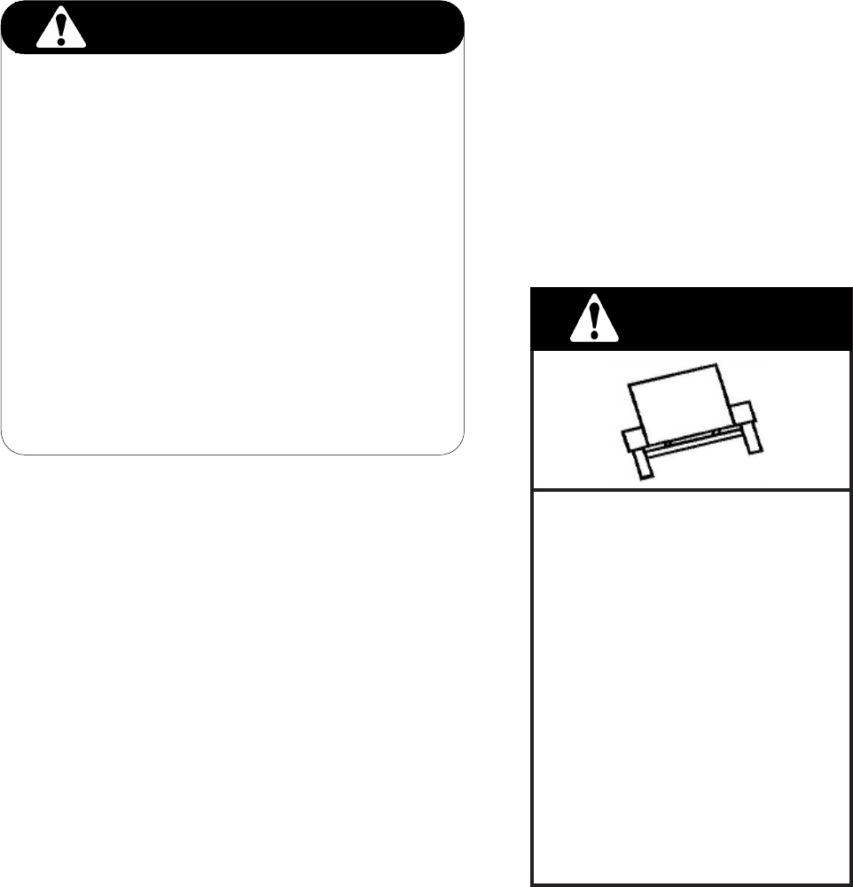
WARNING
CALIFORNIA - Proposition 65 Warning
Engine exhaust and some of its constituents and some dust
created by power sanding, sawing, grinding, drilling and
other construction activities contains chemicals known to the
State of California to cause cancer, birth defects and other
reproductive harm.
Some examples of these chemicals are:-
Lead from lead-based paints
Crystalline silica from bricks
Cement and other masonry products
Arsenic and chromium from chemically
treated lumber
Your risk from these exposures varies, depending on how
often you do this type of work. To reduce your exposure to
these chemicals:
ALWAYS work in a well ventilated area, and work with
approved safety equipment, such as dust masks that are
specially designed to lter out microscopic particles.
3
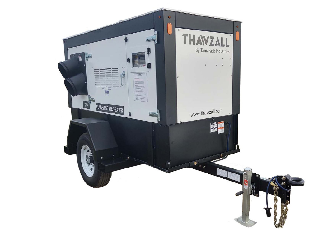
INTRODUCTION
Congratulations on your choice of a Tamarack Industries Thawzall XHR to complement your construction opera-
tion. This equipment has been designed and manufactured to meet the needs of the buyer for the ecient heat-
ing of construction sites.
Safe, ecient and trouble free operation of your XHR requires that you and anyone else who will be operating or
maintaining the Heater, read and understand the Safety, Operation, Maintenance and Trouble Shooting informa-
tion contained in the Operator's Manual.
This manual is applicable to the XHR built by Tamarack Industries. Use the Table of Contents as a guide
when searching for specic information.
Keep this manual handy for frequent reference and to pass on to new operators or owners.
4

Table of contents
Title
Pages
Ways to contact Us 1
Unit Information 2
Proposition 65 warning 3
Introduction 4
Safety 6-11
Warranty 12-13
How it works 14
Controls 15
Operating Procedures 16
Main Screen Overview 17-22
Diagnostics Overview 23-26
Service screen overview 27
Troubleshooting 28-32
Maintenance 33-44
Specications 45
MSDS 46-49
Schematics 50-54
5

Accidents Disable and Kill
Accidents Cost
Accidents Can Be Avoided
Why is SAFETY important to you?
3 Big Reasons
ous situation that, if not avoided, will
result in death or serious injury. This
signal word is to be limited to the most
extreme situations, typically for ma-
chine components that, for functional
purposes, cannot be guarded.
Indicates a potentially hazardous situa-
tion that, if not avoided, could result in
death or serious injury, and includes
hazards that are exposed when guards
are removed. It may also be used to
alert against unsafe practices.
Indicates a potentially hazardous situa-
tion that, if not avoided, may result in
minor or moderate injury. It may also
be used to alert against unsafe prac-
tices.
SIGNAL WORDS:
Note the use of the signal words DANGER,
The Safety Alert symbol identies
important safety messages on the
Tamarack Heat King and in the
manual. When you see this symbol,
be alert to the possibility of personal
injury or death. Follow the instruc-
tions in the safety message.
This Safety Alert symbol means
ATTENTION! BECOME ALERT!
YOUR SAFETY IS INVOLVED!
WARNING and CAUTION with the safety
messages. The appropriate signal word for
each message has been selected using the
following guide-lines:
SAFETY
SAFETY ALERT SYMBOL
DANGER - Indicates an imminently hazard-
WARNING -
CAUTION -
6

Safety, Installation & Operation
SAFETY
YOU are responsible for the SAFE operation and
maintenance of your Tamarack Industries Heat
King. YOU must ensure that you and anyone else
who is going to operate, maintain or work around
the Heat King be familiar with the operating and
maintenance procedures and related SAFETY
information contained in this manual. This manual
will take you step-by-step through your working
day and alerts you to all good safety practices that
should be adhered to while operating the Heater.
Remember, YOU are the key to safety. Good
safety practices not only protect you but also
the people around you. Make these practices a
working part of your safety program. Be certain
that EVERYONE operating this equipment is
familiar with the recommended operating and
maintenance procedures and follows all the safety
precautions. Most accidents can be prevented.
Do not risk injury or death by ignoring good safety
practices.
• Heater owners must give operating instruc-
tions to operators or employees before allow-
ing them to operate the machine, and at least
annually thereafter.
• The most important safety device on this
equipment is a SAFE operator. It is the opera-
tor’s responsibility to read and understand
ALL Safety and Operating instructions in the
manual and to follow these. Most accidents
can be avoided.
• A person who has not read and understood
all operating and safety instructions is not
qualied to operate the machine. An untrained
operator exposes himself and bystanders to
possible serious injury or death.
• Do not modify the equipment in any way.
Unauthorized modication may impair the
function and/or safety and could aect the life
of the equipment.
• The Installation must meet the requirements
of the B138.2,Portable Oil Burning Equip-
ment- installation requirements
• Think SAFETY! Work SAFELY!
GENERAL SAFETY
Only trained competent persons shall operate
the Heater. An untrained operator is not qualied
to operate the machine.
Have a rst-aid kit available for
use, should the need arise and
know how to use it.
Do not allow riders.
Have a re extinguisher available for use
should the need arise and know how to
use it.
Wear appropriate protective gear. This
list includes, but is not
limited to:
- A hard hat
- Protective boots with
slip resistant soles
- Protective goggles
- Heavy gloves
- Hearing protection
Place all controls in their OFF position,
disconnect power cords and wait for all moving
parts to stop before servicing, adjusting or
maintaining
Wear appropriate hearing protection
when operating for long periods of
time.
Wear protective gloves
Ventilation ~ Never operate in a poorly
ventilated or enclose area. Avoid
prolonged breathing of exhaust
gases.
2.
3.
4.
5.
6.
7.
8.
9.
10.
1. Read and understand the
Operator's manual and all
safety signs before
operating, maintaining,
adjusting, servicing or
cleaning the Heater.
7
ELECTRICAL SAFETY
1. Place all controls in their OFF position, discon-
nect power cords and wait for all moving parts to
stop before servicing, adjusting or maintaining.
2. Place all controls in their OFF position before
plugging in power cords.
3. Keep all electrical components in good repair
before starting.
4. Do not lay power lines or connectors in water
or on a wet surface. Dry connectors and raise
power lines out of the water before and during
operation.
5. Do not operate machine if there are electrical
malfunctions. Correct problem before resuming
work.
11. Hot surface ~ Avoid contact with
hot exhaust and glycol system.
Allow to cool before performing repairs
or service.
12. Electrocution Hazard ~ Always use proper size
grounded extension cord. Inspect all extension
cords for cuts, frayed wires and broken connectors.
Do not use cords if not in good condition.
13. Fire Hazard ~ Do not operate
machine in the vicinity of open
ames, sparks or while
smoking.
14. Explosion Hazard ~ Battery
Take care when handling battery
(if installed)
TIRE SAFETY
1. Failure to follow proper procedures when
mounting a tire on a wheel or rim can produce
an explosion which may result in serious injury
or death.
2. Do not attempt to mount a tire unless you have
the proper equipment and experience to do the
job.
3. Have a qualied tire dealer or repair service
perform required tire maintenance.
4. Torque wheel nuts to 120 ft-lbs
STORAGE SAFETY
1. Store unit in an area away from human
activity.
2. Do not permit children to play on or around the
stored Heater.
FUEL SAFETY
Danger: To avoid possible injury, re, or explo-
sion, please read and follow these instruc-
tions.
1. Handle fuel with care. It is highly ammable.
2. Allow burners to cool for 5 minutes before
refueling. Clean up spilled fuel before restarting
engine.
3. Do not refuel the machine while smoking or
when near open ame or sparks.
4. Always use an approved fuel container.
5. Fill fuel tank outdoors.
6. Prevent res by keeping machine clean of ac
cumulated trash, grease and debris.
7
MAINTENANCE SAFETY
1. Review the Operator's Manual and all safety
items before working with, maintaining or
operating the Heater.
2. Place all controls in their OFF position, dis-
connect power cords and wait for all moving
parts to stop before servicing, adjusting or
maintaining.
3. Follow good shop practices:
4. Keep hands, feet, clothing and hair away from
all moving and/or rotating parts.
5. Always wear heavy gloves to prevent burns
when handling hot components. Wait until burn-
ers, coils and glycol system components have
cooled before working on them.
6. Do not attempt any adjustment or maintenance
to any system of the Heater unless the power
wires are disconnected from the battery.
7. Make sure that all guards, shields and hoods
are properly installed and secured before oper-
ating the Heater.
8. Securely support the machine using blocks
or safety stands before working beneath it or
changing tires.
9. Store and transfer diesel fuel, solvents, cleaners
or any ammable liquids only in safety standard
approved containers.
- Keep service
area clean and dry.
- Be sure electri-
cal outlets and tools
are properly ground-
ed.
- Use adequate
light for the job at
hand.
OPERATING SAFETY
1. Read and understand the Operator’s Manual
and all safety signs before operating, servic-
ing, maintaining or adjusting the Heater.
2. Place all controls in their OFF position,
disconnect power cords and wait for all
moving parts to stop before servicing,
adjusting or maintaining.
3. Do not allow riders in or on machine during
transport.
4. Clear the area of bystanders, especially small
children, before starting and operating.
5. Keep the working area clean and free of de-
bris to prevent slipping or tripping. Clean up
fuel spills immediately if they occur.
6. Slow down. Use care when working around
unit - the steps, frame or oor may be wet
and/or slippery.
7. Do not allow personnel that are taking drugs,
alcohol or any medications that impair the
senses or when excessively tired or stressed
to operate the Heater.
8. Do not operate unit in a poorly ventilated or
enclosed area to prevent asphyxiation when
the heaters are operating.
9. Do not smoke when connecting fuel source or
when working around machine.
10. Always wear heavy gloves when working on
the machine to prevent burns when touching
hot components.
11. Use the foot pedal switch to engage the hose
reel take up or extend function and guide the
hose by hand.
12. Keep all electrical lines and components in
good working order. Do not operate in wet
conditions or when standing in water. Damp
or wet conditions can cause shocks or trip the
breakers.
13. Keep all components in good condition.
14.Do Not plug or block access doors or vents.
Keep 1 foot of clearance around unit.
15. Review safety instructions with operators
annually.
9
SAFE TRANSPORTATION AND STORAGE
When transporting the machine, review and follow
these instructions:
1. Be sure all bystanders are clear of the machine.
2. Back the truck up to the hitch and lower hitch
over the ball.
3. Secure with a mechanical retainer.
1. Attach to towing vehicle and secure with a me-
chanical retainer. Cross the safety chains under
the hitch and anchor to truck frame.
2. Connect the brake anchor cable to the truck
frame to activate the trailer brakes if the trailer
unexpectedly unhooks. Provide sucient slack
for turning.
3. Check that all lights and reectors required by
the DOT are clean and functioning.
4. Do not exceed 55 mph under ideal conditions.
5. Do not allow riders on machine.
6. Do not drink and drive.
TRANSPORTING SAFETY
TRAILER TOWING CAN
BE HAZARDOUS
WARNING
* DO NOT exceed 55 mph under ideal
conditions
* Reduce speed under adverse
weather, road or terrain conditions
* Avoid sudden lane changes, U-turns
etc.
* Sudden maneuvers may cause
tipping, rollover, jackkning or sliding
of the trailer and without warning loss
of control of the towing vehicle may
result.
* Allow for increased braking distance
due to weight of trailer
* Read the Operator's Manual before
towing.
4. Cross the safety chains under the hitch and at-
tach to truck frame.
5. Attach the brake line to the truck frame. Be sure
to leave sucient slack for turning.
6. Connect electrical harness to truck plug-in.
7. Raise and secure the hitch jack.
8. Reverse the Heat King set-up procedure t
9. Check and be sure that all lights are working.
10. Do not allow riders on machine.
11. Never exceed a safe travel speed.
12. Do not drink and drive.
13. Check with local highway authorities on the
specic requirements for transporting fuel oil
through their jurisdiction. Always comply with the
requirements before transporting.
10

SIGN-OFF FORM
Tamarack Industries follows the general Safety Standards specied by the Society of Automotive Engi-
neers (SAE) and the Occupational Safety and Health Administration (OSHA). Anyone who will be operat-
ing and/or maintaining the Heat King must read and clearly understand ALL Safety, Operating and Mainte-
nance information presented in this manual.
Do not operate or allow anyone else to operate this equipment until such information has been reviewed.
Annually review this information before the season start-up.
Make these periodic reviews of SAFETY and OPERATION a standard practice for all of your equipment.
We feel that an untrained operator is unqualied to operate this machine.
A sign-o sheet is provided for your record keeping to show that all personnel who will be working with the
equipment have read and understand the information in the Operator’s Manual and have been instructed
in the operation of the equipment.
DATE
EMPLOYEES SIGNATURE
EMPLOYERS SIGNATURE
SIGN-OFF FORM
11

Date Dealer’s Rep. Signature
The above equipment and Operator’s Manual have been received by me and I have been thoroughly
instructed as to care, adjustments, safe operation and applicable warranty policy.
Date Owner's Signature
TAMARACK INDUSTRIES
THAWZALL
WARRANTY REGISTRATION FORM & INSPECTION REPORT
DISTRIBUTOR INSPECTION REPORT
SAFETY
Emergency Stop Switch Works
All Decals Installed and Legible
Lights and Reectors Installed,
Clean and Working
Review Operating And
Safety Instructions
WARRANTY REGISTRATION (please print)
This form must be lled out by the dealer and signed by both the dealer and the customer at the time of deliv-
ery.
Customer’s Name Distributor Name
Address Address
City, State, Code City, State, Code
Phone Number ( ) Check One:
Contact Name Private
THAWZALL Model Contractor
Serial Number Other
Delivery Date
I have thoroughly instructed the buyer on the above described equipment which review included the Op-
erator’s Manual content, equipment care, adjustments, safe operation and applicable warranty policy.
Tire Pressure Checked
Wheel Bolts Torqued
Brakes Work
Check Fluid Levels (Fuel and Glycol)
Lubricate Machine
Check That All Controls Function
12
Tamarack Industries CONDITIONS OF SALES & LIMITED WARRANTY
All sales made by Tamarack Industries, here after ref-
ered to as Tamarack, a Division of ELJO Industries Inc.
are subject to these conditions unless otherwise agreed
in writing with a duly authorized ocer of Tamarack. In
all cases of conict between these conditions and the
requirements of the purchase order, these conditions
shall prevail.
(1) SALES POLICY: Nothing herein shall be construed
as abridging the right of Tamarack to sell directly or indi-
rectly to: (a) Federal, State or Provincial Governments
or Agencies thereof, or to Agencies employing Federal,
State or Provincial Government aid; (b) Purchasers
who buy Tamarack's products for sale as integral or as-
sembled parts of their products; (c) Firms operating on a
national scale; (d) Any other class of purchaser to whom
Tamarack may from time to time, elect to sell.
(2) PRICES: All prices are F.O.B. our warehouses,
freight allowance as specied on Distributor Net Price
Lists. The suggested list prices and discounts schedules
are established by Tamarack and are intended to act as
a guide for our distributors. Unless otherwise stated in
writing, prices are subject to change without notice and
will be applied as in eect at time of shipment.
(3) TERMS: Unless otherwise agreed upon in writing by
an ocer of Tamarack, all invoices become due and pay-
able net 30 days following the date in invoice. Interest
at the maximum legal rate will be charged on all overdue
accounts. Minimum net charge per invoice is $75.00
(4) CANCELLATION AND CHANGES: No orders or
sales may be cancelled or changed without the consent
of Tamarack. At Tamarack's option cancelled/changed
orders are subject to payment of cancellation charges
equal to all costs incurred by Tamarack up to the date
of cancellation/change.
(5) DELAYED DELIVERIES: Tamarack shall not be
liable for any delay of merchandise for any cause what-
soever.
(6) CLAIMS: All goods shall be deemed delivered to pur-
chaser at the time they are placed in the hands of carrier
and consigned to purchaser: loss, damage or destruc-
tion of any said merchandise is assumed by purchaser.
No claims may be made for shortages unless made in
writing within ten days from receipt of merchandise.
(7) RETURN OF GOODS: Written permission from
Tamarack must be obtained before returning any mer-
chandise. All transportation charges must be borne by
the purchaser. Credit for returned goods will be based
on the original price paid, less 20%. Special parts or
custom-built items cannot be returned for credit.
(8) LIMITATION OF LIABILITY: Tamarack's liability on
any claim of any kind, including negligence, for any loss
or damage arising out of, connected with, or resulting
from contract, or the performance or breach thereof, or
the design, manufacture, sale, delivery, resale, installa-
tion, technical direction of installation, inspection, repair,
operation or use of any equipment covered by or fur-
nished under contract shall in no case exceed the price
paid by the purchaser for the equipment. Tamarack also
disclaims all purchaser for the equipment. Tamarack
also disclaims all liability, whether in contract, tort, war-
ranty, or otherwise, to any party other than purchaser.
(9) All Price Lists, Catalogues and other material shall re-
main the property of Tamarack and are subject to return
on demand. The Suggested List Prices are established
by Tamarack and are intended to act as a guide. All
shipping weights shown are approximate.
LIMITED TAMARACK WARRANTY
For two years from date of purchase, Tamarack will
replace or repair for the original purchaser, free of
charge, any part or parts, found upon examination by any
Tamarack Authorized Service Depot or by the Tamarack
factory, to be defective in material or workmanship or
both. Equipment and accessories not manufactured
by Tamarack are warranted only to the extent of the
original manufacturer's warranty. All transportation
charges on parts submitted for replacement or repair
under this warranty must be borne by the purchaser.
For warranty service contact your nearest Tamarack
Authorized Service Depot.
THERE IS NO OTHER EXPRESS WARRANTY,
IMPLIED WARRANTIES, INCLUDING THOSE OF
MERCHANTABILITY AND FITNESS FOR A PARTICU-
LAR PURPOSE ARE LIMITED TO ONE YEAR FROM
PURCHASE AND TO THE EXTENT PERMITTED BY
LAW. LIABILITY FOR CONSEQUENTIAL DAMAGES
UNDER ANY AND ALL WARRANTIES ARE EXCLUD-
ED TO THE EXTENT EXCLUSION IS PERMITTED BY
LAW. (THIS WARRANTY IS AN ADDITION TO ANY
STATUTORY WARRANTY.)
P.O. Box 234, Station "L"
Winnipeg, Manitoba
Canada R3H 0Z5
WARRANTY VOID IF NOT REGISTERED
13
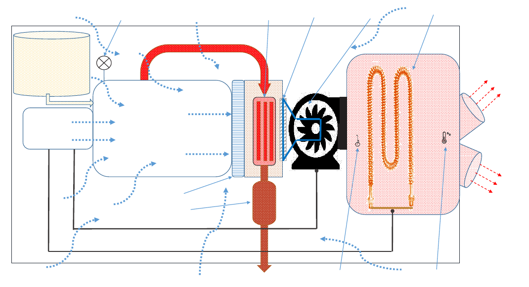
On board Diesel
Fuel Tank
ENGINE
Generator
TO OUTSIDE
RADIATOR
POSITIVE AIR SHUTOFF
FAN
HEATER COILS
CLEAN
HOT AIR
XHR700 : FLAMELESS HEATER
SLIDE GATE
ENGINE EXHAUST
MUFFLER
HEAT EXCHANGER
AIR FLOW SENSOR
AIR TEMP SENSOR
How It Works
Flameless Heater:
This equipment was designed for space heating of buildings under construction, as an outdoor
application with engine exhaust gases discharged outdoors. This unit is a self-contained and does
not require an external power supply.
The XHR has a diesel engine and AC alternator which is used to provide power to the on board
heater bank and blower motor. External air is drawn into the enclosure, this air is then heated by
the residual heat from the internal components. The air is further heated by being drawn through
the coolant radiator and through a heat exchanger utilizing hot exhaust gases. This heated air
is nally blown across a heater bank to increase the air to the desired temperature setting. This
ameless application is well suited for use in hazardous areas where amed heaters cannot be
used. The unit is automated by an onboard computer sytem with user settable temperature and
air speed.
14

15
Controls
8 | Page
PPAARRTT NNUUMMBBEERR:: 660000330077 –– PPRROOGGRRAAMMMMEEDD HHMMII
1. TACTILE KEY’S
1.1. Used for screen navigation & button activation
2. TOUCHSCREEN
2.1. Displays machine graphics & parameters
2.2. Touch activation as described in Screen Operation Section
3. HMI INDICATORS
3.1. Power Indication & Mode Status
3.2. USB Connected
3.3. Network Connected
3.4.
CPU Processing
4. DIAL ENCODER
4.1. Parameter Adjustment
5. HOME KEY
5.1. Returns To Previous Screen
6. ESCAPE KEY
6.1. Returns To Previous Screen
7. USB PORT
7.1. Software Update & Factory Use

16
9 | Page
OPERATIONS
S
S
T
T
A
A
R
R
T
T
U
U
P
P
P
P
R
R
E
E
-
-
M
M
A
A
C
C
H
H
I
I
N
N
E
E
S
S
T
T
A
A
R
R
T
T
U
U
P
P
(PRE-STARTUP INSPECTION PERFORMED)
P
P
R
R
E
E
-
-
A
A
L
L
A
A
R
R
M
M
&
&
E
E
N
N
G
G
I
I
N
N
E
E
S
S
T
T
A
A
R
R
T
T
S
S
E
E
Q
Q
U
U
E
E
N
N
C
C
E
E
1. At the Main Screen or Engine Screen press
2. Provided ECU “Wait to Start” lamp is OFF, HMI buzzer will begin to beep for 5sec
indicating the Engine is about to start
3. HMI will begin to crank the engine until Cutout RPM reached or 10sec elapses
E
E
N
N
G
G
I
I
N
N
E
E
W
W
A
A
R
R
M
M
U
U
P
P
S
S
E
E
Q
Q
U
U
E
E
N
N
C
C
E
E
1. Engine Idles at Idle RPM until High Idle Engine Temp is reached
2. HMI will command engine to High Idle
H
H
E
E
A
A
T
T
C
C
O
O
N
N
T
T
R
R
O
O
L
L
O
O
P
P
E
E
R
R
A
A
T
T
I
I
O
O
N
N
1. HMI turns on Blower after Blower 1 Delay setting
2. HMI Turns on Heater 1 after Heater 1 Delay setting
3. HMI begins Heat Control by cycling heaters 2 thru 4 to achieve desired Heat Setting
selected on Main Screen.
3.1. LOW Setpoint Factory Default: 120DegF
3.2. MED Setpoint Factory Default: 182DegF
3.3. HIGH Setpoint Factory Default: 222DegF
NOTE: The Heat Control also monitors the Engine Load Percentage which may cause the
controller to lower the Heater load for an interval of time. This is to optimize the
performance of the equipment while protecting the wear of the engine.
E
E
N
N
G
G
I
I
N
N
E
E
S
S
H
H
U
U
T
T
D
D
O
O
W
W
N
N
S
S
E
E
Q
Q
U
U
E
E
N
N
C
C
E
E
1. At the Main Screen or Engine Screen press
2. HMI will turn off Heat Control leaving on the Blower Motor ON. ‘SHUTDOWN CYCLE’ is
displayed in message center.
3. HMI will continue run the Blower Motor until LOW IDLE ENGINE TEMP is reached OR 3min
elapses
4. After 5sec HMI will command Engine Idle RPM
5. After 1min HMI will shut off Engine
6. HMI Message Center will display “Machine Ok”
100
150
200
17
10 | Page
SSOOFFTTWWAARREE
M
M
A
A
I
I
N
N
S
S
C
C
R
R
E
E
E
E
N
N
-
-
O
O
V
V
E
E
R
R
V
V
I
I
E
E
W
W
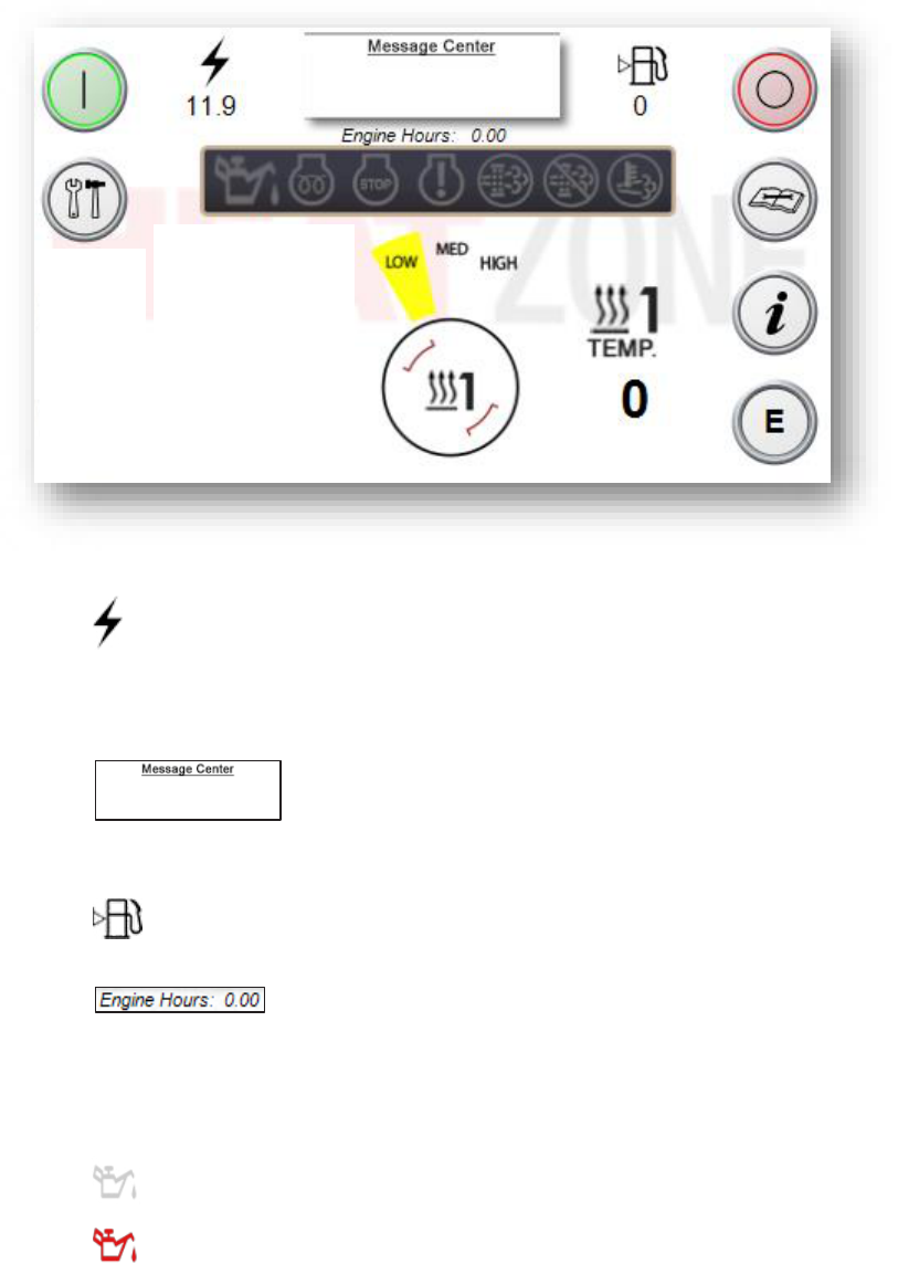
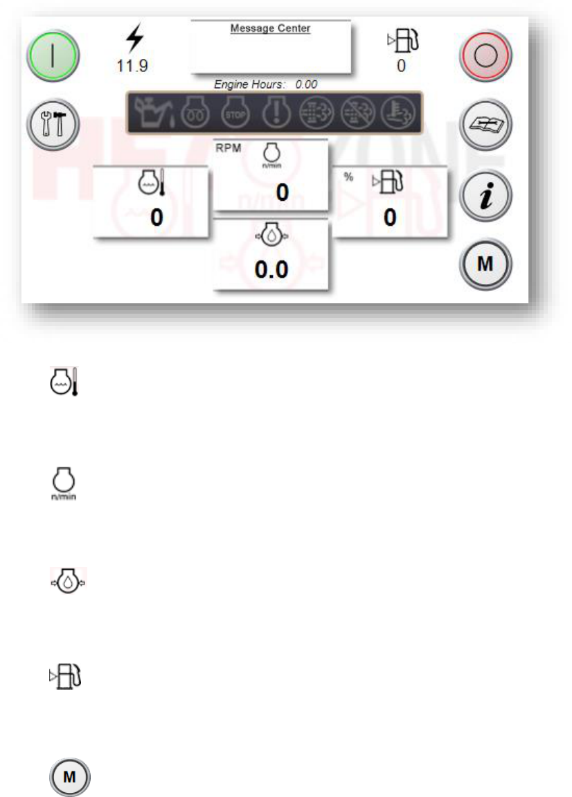
1. DISPLAY
1.1. Engine Battery Voltage is display here. Data is transmitted over J1939
network from Engine.
1.1.1. NOTE: No Engine data is transmitted when the Ignition is OFF.
1.2. Machine status is displayed here including Faults, Warnings,
and Engine Codes.
1.3. Fuel Level is displayed here. Data is transmitter over J1939 from SKIM.
1.4. Engine Hours is displayed here. Data is transmitted over J1939
network from Engine.
1.5.Engine Oil Level is displayed with the following icon. Data is transmitted over
J1939 network from SKIM.
-
Inactive
- Active

18
11 | Page
1.6.Engine Wait is displayed with the following icon. Data is transmitted over J1939
network from Engine. Refer to engine manufacturer for further information.
-
Inactive
- Active
1.7.Engine Stop is displayed with the following icon. Data is transmitted over J1939
network from Engine. Refer to engine manufacturer for further information.
-
Inactive
- Active
1.8.Engine Fault is displayed with the following icon. Data is transmitted over J1939
network from Engine. Refer to engine manufacturer for further information.
- Inactive
- Active
1.9.DPF Active is displayed with the following icon. Data is transmitted over J1939
network from Engine. Refer to engine manufacturer for further information.
- Inactive
- Active
1.10.High Exhaust Temp is displayed with the following icon. Data is transmitted
over J1939 network from Engine. Refer to engine manufacturer for further
information.
- Inactive
- Active
1.11.DPF Disabled is displayed with the following icon. Data is transmitted over
J1939 network from Engine. Refer to engine manufacturer for further
information.
- Inactive
- Active
1.12. Gate Actuator position is displayed here when engine is running at High
Idle
.
1.12.1. NOTE: Only displayed when Actuator is Active in OEM Settings.
19
12 | Page
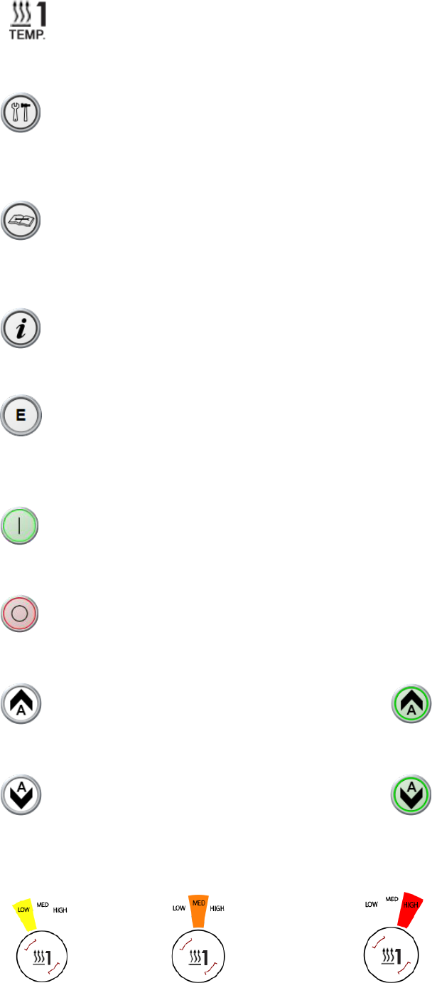
1.13. Duct Temperature is displayed here in Fahrenheit.
2. NAVIGATION
2.1. Press adjacent tactile button or touch screen icon to navigate to SETUP
SCREEN.
2.1.1. NOTE: This feature disappears when equipment is running.
2.2. Press adjacent tactile button or touch screen icon to navigate to
MAINTENANCE SCREEN.
2.2.1. NOTE: This feature disappears when equipment is running.
2.3. Press adjacent tactile button or touch screen icon to navigate to
INFORMATION SCREEN.
2.4. Press adjacent tactile button or touch screen icon to navigate to ENGINE
SCREEN.
3. FUNCTIONS
3.1. System Start is activated here. This initiates the start sequence of the
machine.
3.2. System Stop is activated here. This commands the shutdown sequence of
the machine.
3.3. Gate Open is activated here. Function illuminates when active.
3.3.1. NOTE: Only displayed when Actuator is Active in OEM Settings
3.4. Gate Close is activated here. Function illuminates when active.
3.4.1. NOTE: Only displayed when Actuator is Active in OEM Settings
3.5. Heat Setting is selected by touching the center of the circle in the Heat Setting.
- LOW Setting - MEDIUM Setting - HIGH Setting
20
13 | Page
E
E
N
N
G
G
I
I
N
N
E
E
S
S
C
C
R
R
E
E
E
E
N
N
-
-
O
O
V
V
E
E
R
R
V
V
I
I
E
E
W
W
1. DISPLAY (Notice display features carry over from Main Screen)
1.1. Engine Temp is displayed in the field below this icon. Data is transmitted
over J1939 network from Engine. Refer to engine manufacturer for further
information.
1.2. Engine RPM is displayed in the field below this icon. Data is transmitted
over J1939 network from Engine. Refer to engine manufacturer for further
information.
1.3. Engine Oil Pressure is displayed in the field below this icon. Data is
transmitted over J1939 network from Engine. Refer to engine manufacturer for
further information.
1.4. Fuel Level is displayed in the field below this icon. Data is transmitter over
J1939 from SKIM.
2. NAVIGATION (Notice navigation features carry over from Main Screen)
2.1. Press adjacent tactile button or touch screen icon to navigate to MAIN
SCREEN.
3. FUNCTIONS (Notice function features carry over from Main Screen)
21
14 | Page
S
S
E
E
T
T
U
U
P
P
S
S
C
C
R
R
E
E
E
E
N
N
-
-
O
O
V
V
E
E
R
R
V
V
I
I
E
E
W
W
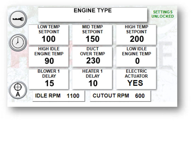
1. DISPLAY
1.1.ENGINE TYPE is the selected engine profile to be controlled
1.1.1. CAT 3.4B
1.1.2. DEUTZ TCD2.9
1.1.3. JOHN DEERE
All temperatures displayed in Fahrenheit
1.2.LOW TEMP SETPOINT is the LOW temperature setting.
1.3.MID TEMP SETPOINT is the MEDIUM temperature setting.
1.4.HIGH TEMP SETPOINT is the HIGH temperature setting.
1.5.HIGH IDLE ENGINE TEMP is the minimum “warm up” temperature the Engine
must reach before proceeding to High Idle startup.
1.5.1. NOTE: High Idle setting is 1800 RPM
1.6.DUCT OVER TEMP is the max allowable temperature within the Duct before the
machine will perform a commanded shutdown sequence.
1.7.LOW IDLE ENGINE TEMP is the minimum “cool down” temperature the Engine
should reach before proceeding to Low Idle shutdown.
1.7.1. NOTE: If this temperature is not reached within 3min the Engine will
proceed to Low Idle and shutdown.
1.8.BLOWER 1 DELAY is the time delay after engine is started to engage the Blower
Motor. Display is in seconds.

22
15 | Page
1.9.HEATER 1 DELAY is the time delay after the Blower Motor is engaged for the
purpose of limiting inrush current. Display is in seconds.
1.10.ELECTRIC ACTUATOR is to enable the Actuator controls when installed.
1.11.IDLE RPM is to set the engines IDLE RPM. This is for qualified personnel ONLY.
1.12.CUTOUT RPM is the RPM at which the start signal will disengage due to the
engine running. This adjustment is for qualified personnel ONLY.
1.13. indicates that access has been granted to modify factory settings.
2. NAVIGATION
2.1. Press adjacent tactile button or touch screen icon to navigate to OEM
LOGIN SCREEN. (Factory Use ONLY)
2.2. Press adjacent tactile button or touch screen icon to navigate to TIME &
DATE SCREEN.
2.3. Press adjacent tactile button or touch screen icon to navigate to
CALIBRATION SCREEN.
2.4. Returns To Previous Screen
3. FUNCTIONS (Settings Unlocked)
3.1. Touch screen over any one of the boxes to enable adjustment. Box will
highlight to indicate adjustment has been enabled . Turn Dial Encoder
clockwise and counterclockwise modify number or selection.
3.1.1. NOTE: Depress Dial Encoder while turning for coarse adjustment in
intervals of 10.
23
20 | Page
DIAGNOSTICS
S
S
O
O
F
F
T
T
W
W
A
A
R
R
E
E
D
D
I
I
A
A
G
G
N
N
O
O
S
S
T
T
I
I
C
C
S
S
C
C
R
R
E
E
E
E
N
N
-
-
O
O
V
V
E
E
R
R
V
V
I
I
E
E
W
W
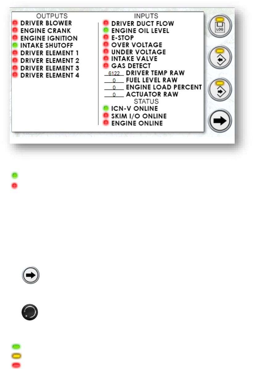
1. DISPLAY
- Function ON/ Device Online
- Function OFF/ Device Offline
1.1.OUTPUTS displays the status for a column of Digital functions being controlled
1.2.INPUTS displays the status for a column of Digital & Analog functions being
monitored.
1.3.STATUS displays the online or offline status of networked devices.
2. NAVIGATION
2.1. Press adjacent tactile button or touch screen icon to navigate to
INFORMATION SCREEN.
2.2. Returns To Previous Screen
3. FUNCTIONS
- Active
- Standby
- Disconnected
24
21 | Page
3.1. Log Export is activated here. Machine log will upload to compatible USB
storage device.
3.2. Parameters Export is activated here. Machine parameters can be
downloaded to compatible USB storage device. (Factory Use)
3.3. Parameters Import is activated here. Machine parameters can be
downloaded to compatible USB storage device. (Factory Use)
I
I
N
N
F
F
O
O
R
R
M
M
A
A
T
T
I
I
O
O
N
N
S
S
C
C
R
R
E
E
E
E
N
N
–
–
O
O
V
V
E
E
R
R
V
V
I
I
E
E
W
W
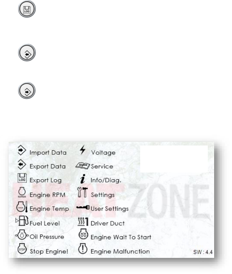
1. DISPLAY
1.1. This screen displays the symbols used within the application with a description
of each.
1.1.1. NOTE: The software version is located in the bottom right of screen.

25
22 | Page
H
H
A
A
R
R
D
D
W
W
A
A
R
R
E
E
C
C
O
O
N
N
T
T
R
R
O
O
L
L
P
P
A
A
N
N
E
E
L
L
1. Back Panel Components
1.1.DC Fuse Holders provide Blown Fuse Status
1.1.1.
1.2.DC Control relays provide ON/OFF LED indication
1.2.1.
1.3.DC Power Supply provides indication that output voltage is good (>90%)
1.3.1.
1.4.Class CC Fuse Holder provide Blown Fuse Status
1.4.1.
1.5.LM1 provides indication of status of the following:
1.5.1. Over-voltage Relay - Yellow
1.5.2. Power On – Green
1.5.3. Under-voltage Relay – Yellow
1.5.4.

26
23 | Page
C
C
H
H
A
A
S
S
S
S
I
I
S
S
C
C
O
O
M
M
P
P
O
O
N
N
E
E
N
N
T
T
S
S
1. 600449R0 – Chassis Harness
1.1.E-STOP Operator provides indication of status
1.1.1. E-STOP pressed – LED ON
1.1.2. E-STOP pulled out – LED OFF
1.1.3.
2. 600318 – Air Flow Sensor
2.1.Sensor provides indication of status
2.1.1. Power/ Standby – Red
2.1.2. Relay Closed – Green
3. Duct Temperature Sensor
3.1.Sensor provides indication of power when Green.
24 | Page
SERVICE
S
S
O
O
F
F
T
T
W
W
A
A
R
R
E
E
S
S
E
E
R
R
V
V
I
I
C
C
E
E
S
S
C
C
R
R
E
E
E
E
N
N
–
–
O
O
V
V
E
E
R
R
V
V
I
I
E
E
W
W
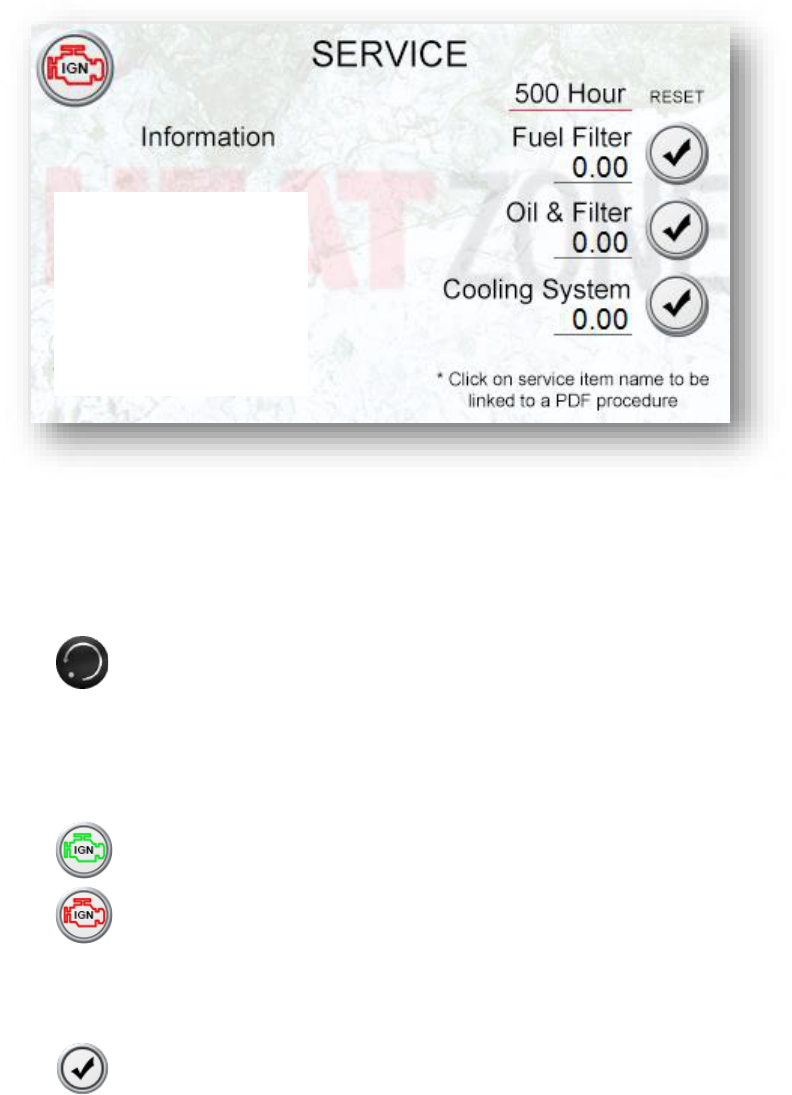
1. NAVIGATION
1.1. Selecting “Information, CAT engine, Deutz Engine, John Deere Engine, Fuel
Filter, Oil & Filter, or Cooling System” will direct you to a PDF containing information
pertaining to that subject.
1.2. Returns To Previous Screen
2. FUNCTIONS
2.1.Engine Ignition can be toggled via screen press or adjacent button. Icon also
displays the status as follows:
-
Ignition ON
- Ignition OFF
500 Hour is a column tracking the engine hours between services for maintenance
required after 500 hours.
2.2. will reset the corresponding service performed
27
28
25 | Page
TROUBLESHOOTING
S
S
O
O
F
F
T
T
W
W
A
A
R
R
E
E
C
C
O
O
M
M
M
M
A
A
N
N
D
D
E
E
D
D
S
S
H
H
U
U
T
T
D
D
O
O
W
W
N
N
F
F
A
A
U
U
L
L
T
T
S
S
Faults that activate shutdown sequence without activating Intake Valve Shutoff
1. CODE: ‘WARNING’ ‘Fuel Level Low’
1.1.CAUSE: Fuel Level dropped below 2%.
1.2.HOW TO CLEAR: Fuel Level must reach >10%.
2. CODE: ‘FAULT’ ‘Fuel Level Sensor’
2.1.CAUSE: Fuel Sensor Signal not detected.
2.2.HOW TO CLEAR: Correct signal.
2.3.POSSIBLE ISSUES: Check wiring or replace sensor.
3. CODE: ‘CYCLE POWER’ ‘Duct Flow Shutdown’
3.1.CAUSE: Flow Sensor input OFF while Blower Motor is ON.
3.2.HOW TO CLEAR: Cycle Power.
3.3.POSSIBLE ISSUES: MMP1 is tripped, inspect sensor indicators and wiring.
4. CODE: ‘CYCLE POWER’ ‘Duct Overtemp Shutdown’
4.1.CAUSE: Duct Overtemp setting reached.
4.2.HOW TO CLEAR: Cycle Power.
4.3.POSSIBLE ISSUES: Duct is blocked, Gate Actuator closed too far, ambient
temperature too high.
5. CODE: ‘FAULT’ ‘Duct Temp Sensor’
5.1.CAUSE: Duct Temp Sensor signal not detected.
5.2.HOW TO CLEAR: Correct signal.
5.3.POSSIBLE ISSUES: Check wiring or replace sensor.
6. CODE: ‘FAULT’ ‘Check Oil Level’
6.1.CAUSE: Oil Level Sensor input OFF indicating oil has dropped below safe level.
6.2.HOW TO CLEAR: Correct signal.
6.3.POSSIBLE ISSUES: Check Oil Level Gauge and wiring. Refer to Factory for
troubleshooting Engine.
7. CODE: ‘FAULT’ ‘Skim IO Offline’
7.1.CAUSE: SKIM IO is not detected on J1939 network.
7.2.HOW TO CLEAR: Correct communication to device.
7.3.POSSIBLE ISSUES: Check power indicators and wiring.
8. CODE: ‘FAULT’ ‘ICN-V Node 5 Offline’
8.1.CAUSE: ICN-V is not detected on CANopen network.
8.2.HOW TO CLEAR: Correct communication to device.
8.3.POSSIBLE ISSUES: Check power indicators and wiring.
29
26 | Page
E
E
M
M
E
E
R
R
G
G
E
E
N
N
C
C
Y
Y
S
S
H
H
U
U
T
T
D
D
O
O
W
W
N
N
F
F
A
A
U
U
L
L
T
T
S
S
Faults that activate immediate shutdown and activate Intake Valve Shutoff
1. CODE: ‘CYCLE POWER’ ‘E-Stop Shutdown’
1.1.CAUSE: E-Stop operator pressed.
1.2.HOW TO CLEAR: Correct Cause & Cycle Power.
2. CODE: ‘CYCLE POWER’ ‘Gas Detect Shutdown’
2.1.CAUSE: Gas Detect Sensor signal ON indicating atmosphere is unsafe to operate.
2.2.HOW TO CLEAR: Correct Cause & Cycle Power.
3. CODE: ‘CYCLE POWER’ ‘Engine Overrev Shutdown’
3.1.CAUSE: Engine RPM exceeded safe operating speed indicating malfunction.
3.2.HOW TO CLEAR: Correct Cause & Cycle Power.
3.3.POSSIBLE ISSUES: Gas is in atmosphere or engine failure. Refer to Factory.
4. CODE: ‘CYCLE POWER’ ‘Undervoltage Shutdown’
4.1.CAUSE: 3-Phase AC power dropped below tolerance.
4.2.HOW TO CLEAR: Correct Cause & Cycle Power.
4.3.POSSIBLE ISSUES: Genset or AVR malfunctioned. Refer to Factory.
5. CODE: ‘CYCLE POWER’ ‘Overvoltage Shutdown’
5.1.CAUSE: 3-Phase AC power exceed upper tolerance.
5.2.HOW TO CLEAR: Correct Cause & Cycle Power.
5.3.POSSIBLE ISSUES: Genset or AVR malfunctioned. Refer to Factory.
M
M
A
A
C
C
H
H
I
I
N
N
E
E
N
N
O
O
T
T
I
I
F
F
I
I
C
C
A
A
T
T
I
I
O
O
N
N
S
S
Codes that serve to notify operator. Some may prevent machine start.
1. CODE: ‘STARTUP CYCLE’
1.1.CAUSE Machine Startup has been activated by operator
1.2.HOW TO CLEAR: No action necessary
2. CODE: ‘SHUTDOWN CYCLE’
2.1.CAUSE: Machine Shutdown has been activated by operator
2.2.HOW TO CLEAR: No action necessary
3. CODE: ‘ACTIVE ENGINE CODE’ ‘SPN## FMI##’
3.1.CAUSE: Engine Error Occurred
3.2.HOW TO CLEAR: Refer to Factory to troubleshoot Engine.
4. CODE: ‘WARNING’ ‘Low Voltage Detected’
4.1.CAUSE: Voltage to HMI dropped below tolerance.
4.2.HOW TO CLEAR: Correct Cause.
4.3.POSSIBLE ISSUES: Check PS1 indicators, bad Voltage Booster, poor Battery
health, inspect wiring.

30
27 | Page
5. CODE: ‘WARNING’ ‘High Engine Temp’
5.1.CAUSE: Engine Temp reached 210degF. This is to warn operator prior to engine
ECM commanding shutdown.
5.2.HOW TO CLEAR: Correct Cause.
6. CODE: ‘WARNING’ ‘Intake Valve Closed’
6.1.CAUSE: Intake Shutoff Valve has not reset by controller. Engine will not start.
6.2.HOW TO CLEAR: Cycle Power or wait for Intake Controller to reset valve.
7. CODE: ‘FAULT’ ‘Inspect Intake Valve’
7.1.CAUSE: Intake Valve signal was not received during emergency shutdown
7.2.HOW TO CLEAR: Correct Cause & Cycle Power.
7.3.POSSIBLE ISSUES: Check wiring.
8. CODE: ‘FAULT’ ‘Actuator NOT Calibrated’
8.1.CAUSE: Actuator Calibration procedure has not been performed.
8.2.HOW TO CLEAR: Perform Calibration Procedure.
9. CODE: ‘FAULT’ ‘Actuator Position Sensor’
9.1.CAUSE: Actuator Position Sensor signal not detected.
9.2.HOW TO CLEAR: Correct Cause.
9.3.POSSIBLE ISSUES: Check wiring or replace Actuator.
10. CODE: ‘FAULT’ ‘Actuator Stalled Detected’
10.1.CAUSE: No position change detected when operating Actuator.
10.2.HOW TO CLEAR: Correct Cause.
10.3.POSSIBLE ISSUES: Obstruction at Gate Actuator or Actuator out of Calibration.
H
H
A
A
R
R
D
D
W
W
A
A
R
R
E
E
S
S
Y
Y
S
S
T
T
E
E
M
M
T
T
R
R
O
O
U
U
B
B
L
L
E
E
S
S
H
H
O
O
O
O
T
T
I
I
N
N
G
G
1. ISSUE: No Power at HMI
POSSIBLE CAUSES:
1.1. Battery Disconnect OFF
1.1.1. Turn ON
1.2. 25A Fuse Blown (P09 – 600449R0)
1.2.1. Needs to be replaced
1.3. 5A Fuse Blown (“F8” – 600435)
1.3.1. Needs to be replaced
1.4. HMI Failure
1.4.1. Needs to be replaced
31
28 | Page
2. ISSUE: No Power at PS1
POSSIBLE CAUSES
2.1. Engine not running at High Idle
2.1.1. Initiate Start Cycle
2.2. 15A Fuse Blown (“F5” – 600435)
2.2.1. Needs to be replaced
3. ISSUE: No Power to LM1
POSSIBLE CAUSES:
3.1.Disconnect OFF
3.1.1. Turn ON
3.2.Fuse Blown at F0 in Genset
3.2.1. Needs to be replaced
3.3.AVR Failure
3.3.1. Refer to Factory
3.4.Genset Failure
3.4.1. Refer to Factory
4. ISSUE: No Power to Blower when MC-1 turns ON
POSSIBLE CAUSES:
4.1.Disconnect OFF
4.1.1. Turn On
4.2.MMP1 Tripped
4.2.1. Inspection by qualified personnel required.
4.3.AVR Failure
4.3.1. Refer to Factory
4.4.Genset Failure
4.4.1. Refer to Factory
5. ISSUE: No Heat while machine running
POSSIBLE CAUSES:
5.1. F1…F4 Fuses Blown
5.1.1. Inspection by qualified personnel required
5.1.2. Needs to be replaced
5.2. MC1…4 Failure.
5.2.1. Needs to be replaced
5.3. Heater Failure.
5.3.1. Refer to Factory
6. ISSUE: Running Lights not ON while machine running
POSSIBLE CAUSES:
6.1. 10A Fuse blown (“F9” – 600435).
6.1.1. Needs to be replaced
6.2. Light Failure.
6.2.1. Needs to be replaced.
6.3. Relay Failure (“R3” - 600435).
6.3.1. Needs to be replaced.
32
29 | Page
7. ISSUE: Engine not Online
POSSIBLE CAUSES:
7.1. Ignition not ON or Start Cycle has not been initiated
7.2. Emergency condition NOT cleared
7.2.1. See Message Center on HMI and refer to Software Codes.
7.3. 25A Fuse blown (P09 – 600449R0)
7.3.1. Needs to be replaced.
7.4. 5A Fuse Blown (“F8” – 600435)
7.4.1. Needs to be replaced.
8. ISSUE: Engine Starter will not engage after Pre-Start alarm
POSSIBLE CAUSES:
8.1. Wait to Start required by Engine ECM.
8.1.1. See indicators on HMI and refer to Screen Layout.
8.2. 25A Fuse blown (P09 – 600449R0)
8.2.1. Needs to be replaced.
8.3. 5A Fuse Blown (“F8” – 600435)
8.3.1. Needs to be replaced.
8.4. Engine Starter Failure.
8.4.1. Refer to Factor for troubleshooting Engine.

Maintenance
NOTE: The Thawzall XHR can be equipped with a DEUTZ or FIAT engine.
Please refer to the appropriate service information for your engine.
Top level maintenance is provided in this section. For detailed engine maintenance procedures
please refer to the engine manufacturers operation and maintenance manual supplied with your
heater. There you will nd a full range of maintenance procedures and maintenance scheduling.
DATE HOURS SERVICED BY SERVICE PERFORMED
Maintenance Record
33
XHR Engine Maintenance Chart
Description Operation Every
350
Hours
Every
500
Hours
Monthly
Engine oil Change X
Engine Oil
lter
Change X
Engine Air
Filter
Check
Engine Fuel
lter
Change
Grease Axle
Hubs
Service X
Torque
Wheel Nuts
(120 ft/lbs)
Check X
Service Parts
Description Part Number/ Type
Engine Oil See Engine Manual
Engine Oil Filter 0117 4416
Engine Air Filter (inner) 0118 0871
Engine Air Filter (outer) 0131 9258
Engine Fuel Filter 0413 7456
Engine Fuel/Water Separator 0413 0241
Refer to engine manual for greater detail
35
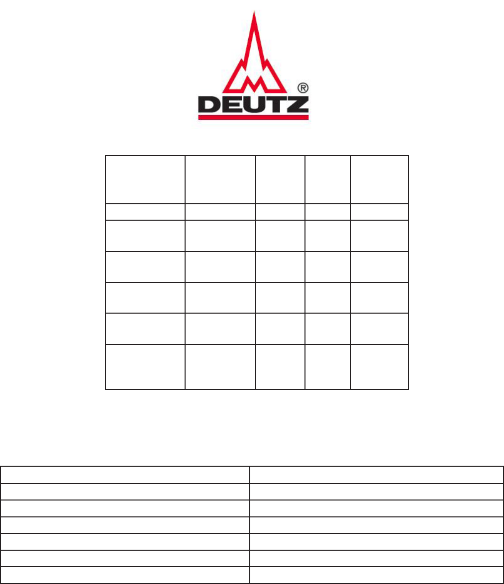
Deutz Engine

XHR Engine Maintenance Chart
Description Operation Every
600
Hours
Every
1200
Hours
Monthly
Engine oil Change X
Engine Oil
lter
Change X
Engine Air
Filter
Check X
Engine Fuel
lter
Change X
Grease Axle
Hubs
Service X
Torque
Wheel Nuts
(120 ft/lbs)
Check X
Service Parts
Description Part Number/ Type
Engine Oil See Engine Manual
Engine Oil Filter 5802431041
Engine Air Filter (inner) P822769
Engine Air Filter (outer) 8050800
Engine Fuel Filter 5801693493
Engine Fuel/Water Separator 504372615
Refer to engine manual for greater detail
36
Fiat Engine
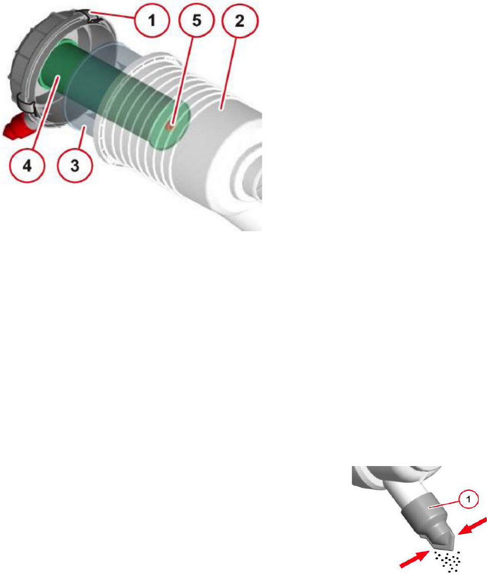
Air Filter
38
• Empty the dust discharge valve (1) by pressing together the dischage slit.
• Remove and stuck on dust residues by squeezing the upper area of the valve.
• Clean the discharge slit.
Clean the air lter dust discharge valve
Refer to engine manual for greater detail
1. Clamp
2. Filter hood
3. Outer air lter
4. Inner air lter
5. Hexagon nut
Maintaining the Air lter
NOTICE
Do not clean the air lter with chemicals or hot liquids!
• Maintain the lter elements according to the interval in the maintenance schedule
• Lift the clamps to open the housing
• Pull out the lter element, blow out with compressed air from the inside to the
outside if soiling is only slight.
• Replace if heavily soiled.
• Unscrew hexagonal nut
• Replace inner and outer lters
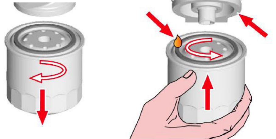
Fuel Filter
Remove
Remove the spin-on fuel lter with a lter wrench, collect escaping fuel.
Install
Do not pre-ll an on-engine fuel lter with fuel. Prelling the fuel lter can result in debris enter-
ing the fuel system and damaging fuel system components Lubricate the O-ring seal with clean
lubrication oil.
Use the correct fuel lter. See the service parts page for the correct part number for your engine.
Install the lter on the lter head. Tighten the lter until the gasket contacts the lter head surface.
Tighten the fuel lter an additional ¾ turn after contact, or consult the lter manufacturer instruc-
tions.
Prime fuel system after lter installation.
WARNING
The fuel pump high-pressure fuel lines and fuel rail contain very high-pressure fuel. Never loosen
any ttings while the engine is running. Personal injury and property damage can result.
To prime the engine use the OEM installed priming device. Typically, a priming pump is installed at
or near the prelter. See the OEM’s instructions for the number of strokes (hand primer) or cycles
time (electric priming pump) needed to prime the low pressure system.
Operate the engine and check for leaks.
39
Change fuel lter
Fuel/Water Separator
DEUTZ ENGINE
1. Fuel supply ow to the pump
2. Venting Screw
3. Electrical connection for water level sensor.
4. Drain Plug
5. Filter Cartridge
6. Fuel supply from the tank
Draining Water
• Shut down engine.
• Place suitable container underneath.
• Disconnect electrical connection.
• Loosen drain plug.
• Drain until pure fuel runs out.
• Tighten drain plug.
• Connect electrical connection
Changing the Pre-lter insert
• Shut down engine
• Place suitable container underneath.
• Disconnect electrical connection.
• Loosen drain plug and drain liquid.
• Dissasemble lter insert.
• Clean any dirt o of the sealing surfaces
• Wet the sealing surfaces of the lter car-
tridge with fuel and screw back on to the
lter head, clockwise.
• Tighten drain plug.
• Connect electrical connection
• Prime the fuel system.
Priming the Fuel System
NOTICE
Do not crank the engine continuously for
more than 30 seconds. Allow the starting
motor to cool for two minutes before crank-
ing the engine again.
The fuel system is primed via the electric
fuel supply pump.
In order to ensure that no error messages
are generated, no attempt should be made
to start the system whilst priming.
Priming
Refer to engine manual for greater detail
40
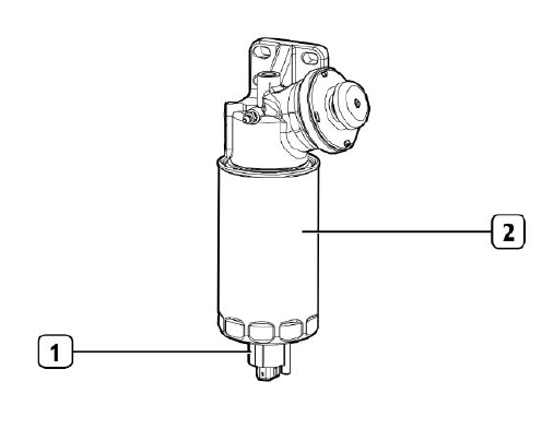
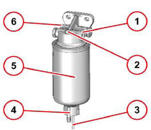
Fuel/Water Separator
FIAT ENGINE
1. Drain Valve
2. Filter
Draining Water
• Shut down engine.
• Place suitable container underneath.
• Disconnect electrical connection.
• Loosen drain plug.
• Drain until pure fuel runs out.
• Tighten drain plug.
• Connect electrical connection
Changing The Filter Element
• Shut down engine
• Place suitable container underneath.
• Disconnect electrical connection.
• Loosen drain plug and drain liquid.
• Dissasemble lter insert.
• Clean any dirt o of the sealing surfaces
• Wet the sealing surfaces of the lter car-
tridge with fuel and screw back on to the
lter head, clockwise.
• Tighten drain plug.
• Connect electrical connection
• Vent the fuel system.
Priming the Fuel System
NOTICE
Do not crank the engine continuously for
more than 30 seconds. Allow the starting
motor to cool for two minutes before crank-
ing the engine again.
• Ensure the fuel system is in working
order and the supply valve is in the “on”
position ( if equipped)
• Operate the hand priming pump. Count
the number of operations of the pump.
After approximately 80 depressions of
the pump stop.
• The fuel system should now be primed
and the engine should be able to start.
• Operate the engine starter and crank
the engine.After the engine has started,
operate the engine at low idle for a mini-
mum of 5 minutes to ensure the system
is free from leaks.
NOTE
Do not loosen the high pressure fuel lines
in order to purge air from the system. This
procedure is not required.
Refer to engine manual for greater detail
42
Engine Oil and Filter
To reduce the possibility of personnel injury, avoid direct contact of hot oil with your skin.
Danger of scalding! Do not pull out the dipstick with the engine running. Danger of injury!
NOTE: For most engines, use a container that can hold at least 20 liters (21qt) of lubricating oil.
Change the lubricating oil and lter at the specied oil change interval. See the maintenance
schedule to nd the correct change interval for your application.
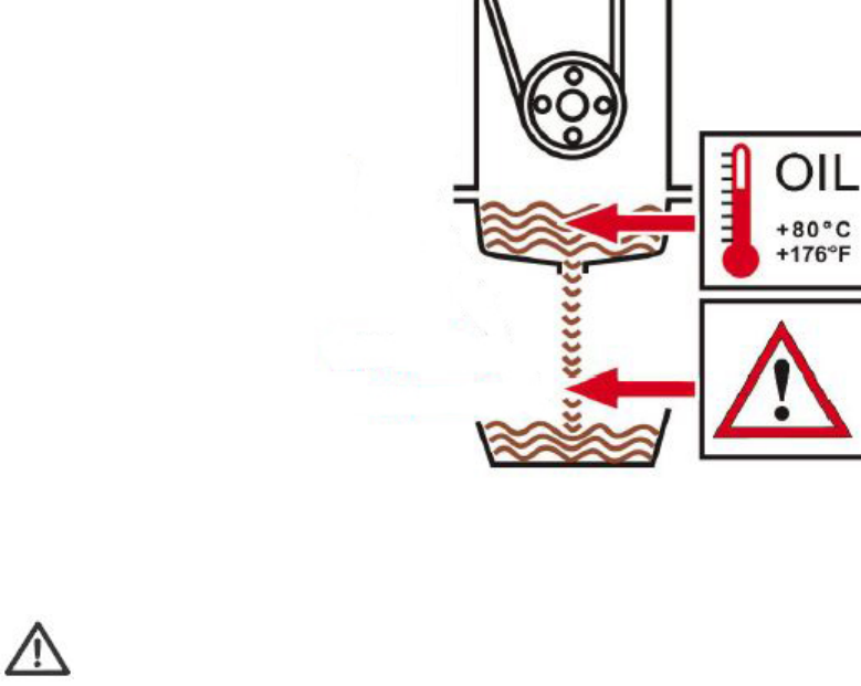
1. Operate the engine until the temperature reaches 80°C (176°F).
2. Shut o the engine
3. Position drain pan under the oil drain plug.
4. Remove the oil drain plug. Drain the oil immediately to be sure all the oil and suspended con-
taminants are removed from the engine.
5. Turn in and tighten oil drain plug .
42
Oil Drain

REMOVE
Clean the area around the lubricating oil lter head.
Use an oil lter wrench to remove the lter.
Clean the gasket surface of the lter head.
NOTE: The O-ring can stick on the lter head. Be sure it is removed before installing the new
lter.
Install
Use the correct oil lter. See the service parts page for the correct oil lter part number.
Use clean oil to coat the gasket surface of the lter.
Apply a light lm of lubricating oil to the gasket sealing surface before installing the lter.
NOTE: Be careful the no debris is poured into the lter. If using an oil supply with a metallic or
plastic seal under the cap, be careful to peel the seal back. Punching the seal with a knife or
sharp object can create debris in the oil container.
CAUTION
Mechanical overtightening of the lter can distort the threads or damage the lter sealing element
seal. Install the lter on the oil lter head. Tighten the lter until the gasket contacts the lter
head surface. Tighten ¾ turn after the gasket makes contact with the lter head.
43
Change oil lter
OIL LEVEL MAINTENANCE CHECK
CAUTION
Never operate the engine with oil level below the MIN level or above the MAX level. Poor engine
performance or engine damage can occur.
The engine must be level when checking the oil level to make sure the measurement is correct.
Shut o the engine for an accurate reading.
Wait at least 15 minutes after shutting o the engine to check the oil level. This allows time for
the oil to drain into the oil pan.
44
Fill
Clean and check the lubricating oil drain plug threats and sealing surface. Use a new sealing
washer, if damaged.
Install the lubricating oil pan plug.
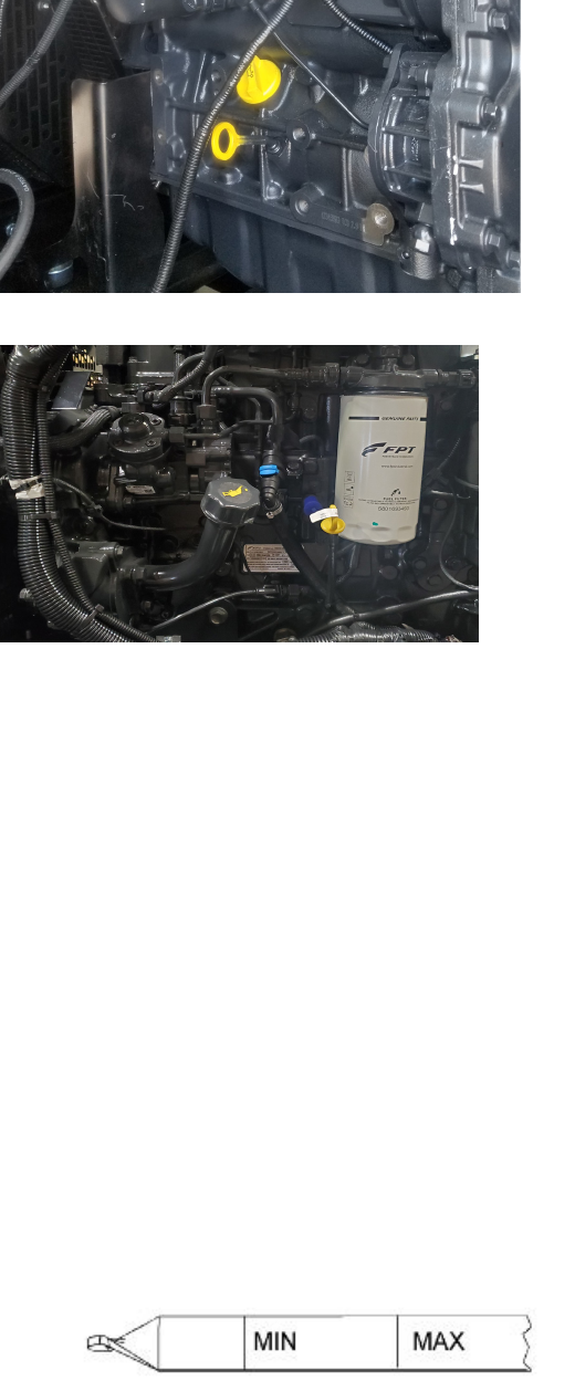
DEUTZ ENGINE
FIAT ENGINE
Fill the engine with clean lubricating oil to the proper level.
Idle the engine to inspect for leaks at the drain plug and , if replaced, the oil lter seal.
NOTE: Engine oil pressure must be indicated on the gauge within 15 seconds after starting. If oil
pressure is not registered within 15 seconds, shut o the engine immediately to avoid engine dam-
age. Conrm that the correct oil level is in the oil pan.
Shut o the engine. Wait approximately 5 minutes to let the oil drain from the upper parts of the
engine. Check the level again. Add oil as necessary to bring the oil level to the H (high) mark on
the dipstick.

XHR Specications
Performance Specications
General Capacities and Component Specications
Height (w/ heater vent)
94.5”
Width 77”
Length 160”
Weight ( Fuel Empty/Full) 5300/6400 LBS
Engine (2 options) Deutz / Fiat F34
Air Ducts 2 x 12”
Heater Element 480V Electric
Trailer and Fuel Tank
Axles 7000 Lb. With Electric Brakes
Tires ST235/80R-16
Tire Ination Pressure 80 PSI
Wheel Nut Torque 120 FT-LBS
Hitch 2-5/16” Ball or Pintle
Tie Downs 4 For Transporting
Fuel Tank Capacity 160 US Gallons
Ground Clearance 14”
Containment 173%
Nominal Heat Output 572,000 BTU/H
Fuel Requirement #1 or #2 Diesel Fuel
Fuel Consumption 4.5 GPH MAX
Run Time Min 35 Hrs @ 100%
Air Flow Variable Max 4500 CFM
45
Section 1. Chemical Product and Company Identification
Material Safety Data Sheet
WHMIS (Pictograms) Protective Clothing
Product Name
Synonym
Code
DIESEL FUEL
Diesel 50, Diesel 50 LS, #1 Diesel , #1 Diesel LS, Diesel LC, Seasonal Diesel,
Seasonal Diesel LS, Diesel AA, Domestic Marine Diesel, International marine
Diesel, Seasonal Diesel Locomotive, Domestic Marine diesel LS, diesel -20°C
(LS), LSD, Low Sulphur Diesel, dyed diesel, marked diesel, coloured diesel,
Naval Distillate.
W104
SAP: 120, 121, 122, 287
Diesel fuels are distillate fuels suitable for use in high and medium speed
internal combustion engines of the compression ignition type.
In case of
Emergency
Petro-Canada: 403-296-3000
Canutec Transportation:
613-996-6666
Poison Control Centre: Consult
local telephone directory for
emergency number(s).
PETRO-CANADA
P.O. Box 2844
Calgary, Alberta
T2P 3E3
WHMIS (Classification)
B-3, D-2B
TDG (pictograms)
3
Manufacturer
Material Uses
Validated on 3/2/2001.
1) Diesel oil.
68334-30-5 >99.9 Not established* Not established Not established
2) Proprietary additives.
Not available <0.1 Not established Not established Not established
3) Aromatic content is 50% maximum ( benzene: nil).
4) * Notice of Intended Change (2000): 100 mg/m³, skin,
A3.
Section 2. Composition and Information on Ingredients
Name
CAS #
Exposure Limits (ACGIH)
CEILING% (V/V) TLV-TWA(8 h) STEL
Manufacturer
Recommendation
Not applicable
Consult local, state, provincial or territory authorities for acceptable exposure limits.
Other Exposure Limits
Section 3. Hazards Identification.
Eye contact may cause mild eye irritation. Skin contact can cause moderate to severe irritation and produce drying,
cracking, or defatting dermatitis. Inhalation of vapours can cause CNS depression with symptoms of nausea, headaches,
vomiting, dizziness, fatigue, light-headedness, reduced coordination, unconciousness and possibly death. Inhalation can also
cause irritation of nose and throat. Aspiration of liquid drops into the lungs may produce potentially fatal chemical
pneumonitis (fluid in the lungs), severe lung damage, or respiratory failure. For more information, refer to Section 11.
Potential Health
Effects
DO NOT induce vomiting because of danger of aspirating liquid into lungs. Seek medical attention.
Eye Contact
Skin Contact
Inhalation
Ingestion
IMMEDIATELY flush eyes with running water for at least 15 minutes, keeping eyelids open. Seek medical attention.
Remove contaminated clothing - launder before reuse. Wash gently and thoroughly the contaminated skin with running water
and non-abrasive soap. Seek medical attention.
Evacuate the victim to a safe area as soon as possible. If the victim is not breathing, perform artificial respiration. Allow the
victim to rest in a well ventilated area. Seek medical attention.
Section 4. First Aid Measures
Note to Physician
Not available
Auto-Ignition
Temperature
Products of
Combustion
Flash Points
Flammable Limits
Fire Hazards
in Presence of
Various
Substances
225ºC (437ºF)
Carbon oxides (CO, CO2), nitrogen oxides (NOx), sulphur oxides (SOx), sulphur compounds (H2S), water vapour (H2O),
smoke and irritating vapours as products of incomplete combustion.
Diesel Fuel: Closed Cup: >40ºC (>104ºF)
Marine Diesel Fuel: Closed Cup: >60ºC (>140ºF)
LOWER: 0.7%, UPPER: 6%
Flammable in presence of open flames, sparks, or
heat. Vapours are heavier than air and may travel
considerable distance to sources of ignition and
flash back. This product can accumulate static
charge and ignite. May accumulate in confined
spaces.
Explosion
Hazards in
Presence of
Various
Substances
Containers may explode in heat of fire. Do not
cut, weld, heat, drill or pressurize empty
container. Vapour explosion hazard indoors,
outdoors or in sewers. Runoff to sewer may
create fire or explosion hazard.
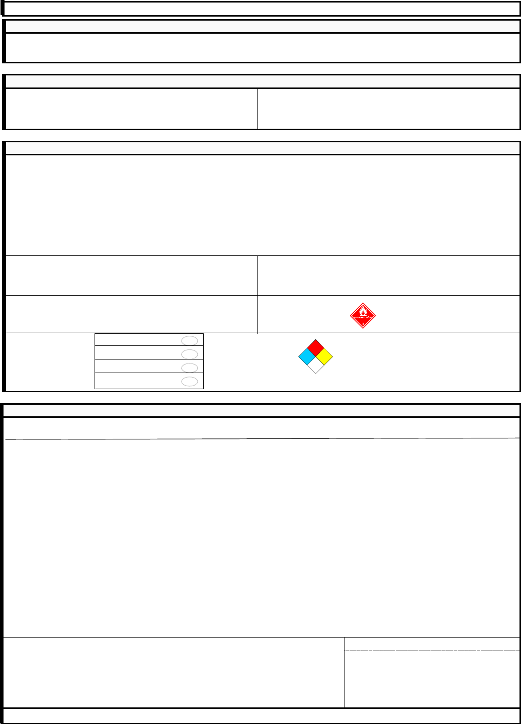
Flammability
Class II - combustible liquid (NFPA).
Section 5. Fire-fighting Measures
Continued on Next Page Available in French
46

DIESEL FUEL Page Number: 2
Fire Fighting
Media and
Instructions
NAERG96, GUIDE 128, Flammable liquids (Non-polar/Water-immiscible).
CAUTION: This product has a moderate flash point above 40ºC: Use of water spray when fighting fire may be inefficient.
If tank, rail car or tank truck is involved in a fire, ISOLATE for 800 meters (1/2 mile) in all directions; also consider initial
evacuation for 800 meters (1/2 mile) in all directions.
SMALL FIRES: Dry chemical, CO2, water spray or regular foam.
LARGE FIRES: Water spray, fog or regular foam. Do not use straight streams. Move containers from fire area if you can do
it without risk.
Fires Involving Tanks or Car/Trailer Loads: Fight fire from maximum distance or use unmanned hose holders or monitor
nozzles.
Cool containers with flooding quantities of water until well after fire is out. Withdraw immediately in case of rising sound from
venting devices or any discolouration of tank. ALWAYS stay away from the ends of tanks. For massive fire, use unmanned
hose holders or monitor nozzles; if this is impossible withdraw from area and let fire burn. Wear positive pressure
self-contained breathing apparatus (SCBA). Structural firefighters' protective clothing will only provide limited protection.
Section 6. Accidental Release Measures
Material Release
or Spill
NAERG96, GUIDE 128, Flammable Liquids (Non-polar/ Water-immiscible).
ELIMINATE ALL IGNITION SOURCES. Avoid contact. Stop leak if without risk. Contain spill. Absorb with inert absorbents,
dry clay, or diatomaceous earth. Avoid inhaling dust of diatomaceous earth for it may contain silica in very fine particle size,
making this a potential respiratory hazard. Place used absorbent in closed metal containers for later disposal or burn
absorbent in a suitable combustion chamber. DO NOT FLUSH TO SEWERS, STREAMS OR OTHER BODIES OF WATER.
Check with applicable jurisdiction for specific disposal requirements of spilled material and empty containers. Notify the
appropriate authorities immediately.
Storage
Store in tightly closed containers in cool, dry, isolated, well-ventilated area, and away from incompatibles. Ground all
equipment containing material.
Keep away from heat. Keep away from sources of ignition. Empty containers pose a fire risk. DO NOT reuse empty
containers without commercial cleaning or reconditioning. Ground/bond line and equipment during pumping or transfer to
avoid accumulation of static charge. DO NOT ingest. Do not breathe gas/vapour/spray. In case of insufficient ventilation,
wear suitable respiratory equipment. If ingested, seek medical advice immediately. Avoid contact with skin and eyes.
Practice good personal hygiene. Wash hands after handling and before eating. Launder work clothes frequently. Discard
saturated leather goods.
Handling
Section 7. Handling and Storage
Engineering Controls
Personal Protection -
The selection of personal protective equipment varies, depending upon conditions of use.
For normal application, special ventilation is not necessary. If user's operations generate vapours or mist, use ventilation to
keep exposure to airborne contaminants below the exposure limit. Make-up air should always be supplied to balance air
removed by exhaust ventilation. Ensure that eyewash station and safety shower are close to work-station.
Wear appropriate footwear to prevent product from coming in contact with feet and skin.
Section 8. Exposure Controls/Personal Protection
Eyes
Body
Respiratory
Hands
Feet
Wear appropriate chemically protective gloves. When handling hot product ensure gloves are heat resistant and insulated.
Where concentrations in air may exceed the occupational exposure limits given in Section 2 (and those applicable to your
area) and where engineering, work practices or other means of exposure reduction are not adequate, NIOSH approved
respirators may be necessary to prevent overexposure by inhalation.
Wear appropriate clothing to prevent skin contact. As a minimum long sleeves and trousers should be worn.
Eye protection (i.e., safety glasses, safety goggles and/or face shield) should be determined based on conditions of use. If
product is used in an application where splashing may occur, the use of safety goggles and/or a face shield should be
considered.
Section 9. Physical and Chemical Properties
Physical State and
Appearance
Boiling Point
Odour Threshold
Density
Vapour Density
Oil / Water Dist.
Coefficient
Bright oily liquid.
0.85 kg/L @ 15ºC (Water = 1).
4.5 (Air = 1)
Not available
Petroleum oil like.
Odour
Variable, 0ºC to -50ºC (32ºF to -58ºF)Clear to yellow / brown. Low sulphur diesel
fuels (<0.05 wt % sulphur) are colourless to
light yellow (and may be dyed red for taxation
purposes). Regular sulphur diesel fuels
(0.05-0.50 % sulphur) may be colourless to
yellow / brown and are usually dyed red for
taxation purposes.
Colour
Dropping Point
Penetration
Not applicable.
Not applicable.
Viscosity
1.3-4.1 cSt @ 40ºC (104ºF)
Pour Point
Softening Point
150-371ºC (302-700ºF)
Ionicity (in water)
Not applicable.
Not applicable.
Not available
Continued on Next Page Available in French
47

DIESEL FUEL Page Number: 3
Volatility
Vapour Pressure
Solubility
<0.1 (Butyl acetate = 1), less than gasoline.
1.0 kPa @ 20ºC (7.5 mmHg @ 68ºF).
Insoluble in cold water, soluble in non-polar
hydrocarbon solvents.
Dispersion Properties
Not available
Stability
Corrosivity
The product is stable under normal handling
and storage conditions.
Not available
Reactive with oxidizing agents and acids.
Section 10. Stability and Reactivity
Incompatible
Substances /
Conditions to Avoid
Decomposition
Products
May release COx, NOx, SOx, H2S, H2O, smoke and
irritating vapours when heated to decomposition.
Hazardous
Polymerization
Will not occur under normal working conditions.
Acute Lethality
Routes of Entry
Skin contact, eye contact, inhalation, and ingestion.
Acute oral toxicity (LD50): 7500 mg/kg (rat).
Section 11. Toxicological Information
Other Considerations
No additional remark.
Chronic or Other Toxic EffectsChronic or Other Toxic Effects
Dermal Route:
Inhalation Route:
Oral Route:
Eye Irritation/Inflammation:
Immunotoxicity:
Skin Sensitization:
Respiratory Tract Sensitization:
Mutagenic:
Reproductive Toxicity:
Teratogenicity/Embryotoxicity:
Carcinogenicity (ACGIH):
Carcinogenicity (IARC):
Carcinogenicity (NTP):
Carcinogenicity (IRIS):
Carcinogenicity (OSHA): This product is not known to contain any chemicals at reportable quantities that are listed as carcinogens by
OSHA.
Not available
This product is not known to contain any chemicals at reportable quantities that are listed as carcinogens by
NTP.
This product is not known to contain any chemicals at reportable quantities that are listed as group 1, 2A or 2B
carcinogens by IARC.
ACGIH Notice of Intended Changed (2000): proposed A3: animal carcinogen. [Diesel oil]
This product is not expected to be a teratogen or an embryotoxin, based on the available data and the known
hazards of the components.
This product is not expected to be a reproductive hazard, based on the available data and the known hazards of
the components.
This product is not expected to be a mutagen, based on the available data and the known hazards of the
components.
This product is not expected to be a respiratory tract sensitizer, based on the available data and the known
hazards of the components.
This product is not expected to be a skin sensitizer, based on the available data and the known hazards of the
components.
Not available
Eye contact may cause mild irritation, but no permanent damage.
Aspiration of liquid drops into the lungs may produce potentially fatal chemical pneumonitis (fluid in the lungs),
severe lung damage, or respiratory failure.
Inhalation of vapours can cause CNS depression with symptoms of nausea, headaches, vomiting, dizziness,
fatigue, light-headedness, reduced coordination, unconciousness and possibly death. Inhalation can also cause
irritation of nose and throat.
Skin contact may cause moderate to severe irritation. Repeated exposure would produce drying and cracking or
defatting dermatitis.
Section 12. Ecological Information
Environmental
Fate
Not available
BOD5 and COD Products of
Biodegradation
Persistance/
Bioaccumulation
Potential
Additional Remarks
Not available Not available
Not available
No additional remark.
Continued on Next Page Available in French
48
DIESEL FUEL Page Number: 4
Section 13. Disposal Considerations
Waste Disposal
Preferred waste management priorities are: (1) recycle or reprocess; (2) incineration with energy recovery; (3) disposal at
licensed waste disposal facility. Ensure that disposal or reprocessing is in compliance with government requirements and
local disposal regulations. Consult your local or regional authorities.
Section 14. Transport Information
TDG Classification Special Provisions
for Transport
Diesel Fuel
UN1202
3
III
Not applicable.
0
Personal Protection
Health Hazard
This product is acceptable for use under the provisions of WHMIS-CPR. All components of this formulation are listed on the
CEPA-DSL (Domestic Substances List).
All components of this formulation are listed on the US EPA-TSCA Inventory.
All components of this product are on the European Inventory of Existing Commercial Chemical Substances (EINECS).
This product has been classified in accordance with the hazard criteria of the Controlled Products Regulations (CPR) and the
MSDS contains all of the information required by the CPR.
Please contact Product Safety for more information.
2*
2
H
Section 15. Regulatory Information
Other
Regulations
DSD/DPD (Europe)
ADR (Europe)
(Pictograms)
DOT (U.S.A)
(Pictograms)
NFPA (U.S.A.)HMIS (U.S.A.)
Not evaluated.
Fire Hazard
Reactivity
Health
Fire Hazard
Reactivity
Specific hazard
2
2 0
NOT EVALUATED FOR
EUROPEAN TRANSPORT
NON ÉVALUÉ POUR LE
TRANSPORT EUROPÉEN.
Rating
1
3
4
2
0
Slight
Moderate
Extreme
High
Insignificant
HCS (U.S.A.)
CLASS: Irritating substance.
CLASS: Target organ effects.
CLASS: Combustible liquid having a flash point
between 37.8°C (100°F) and 93.3°C (200°F).
Prepared by Product Safety - TAR on 3/2/2001.
Data entry by Product Safety - JDW.
References
Available upon request.
* Marque de commerce de Petro-Canada - Trademark
Section 16. Other Information
Fuels & Solvents:
Western Canada, telephone: 403-296-4158; fax: 403-296-6551
Ontario & Central Canada, telephone: 1-800-668-0220; fax: 1-800-837-1228
Quebec & Eastern Canada, telephone: 514-640-8308; fax: 514-640-8385
For Product Safety Information: (905) 804-4752
For Copy of MSDS
Glossary
ACGIH - American Conference of Governmental Industrial Hygienists
ADR - Agreement on Dangerous goods by Road (Europe)
ASTM - American Society for Testing and Materials (
BOD5 - Biological Oxygen Demand in 5 days
CAN/CGA B149.2 Propane Installation Code
CAS - Chemical Abstract Services
CEPA - Canadian Environmental Protection Act
CERCLA - Comprehensive Environmental Response, Compensation and Liability Act
CFR - Code of Federal Regulations
CHIP - Chemicals Hazard Information and Packaging Approved Supply List
COD5 - Chemical Oxygen Demand in 5 days
CPR - Controlled Products Regulations
DOT - Department of Transport
DSCL - Dangerous Substances Classification and Labeling (Europe)
DSD/DPD - Dangerous Substances or Dangerous Preparations Directives (Europe)
DSL - Domestic Substance List
EEC/EU - European Economic Community/European Union
EINECS - European Inventory of Existing Commercial Chemical Substances
EPCRA - Emergency Planning and Community Right to Know Act
FDA - Food and Drug Administration
FIFRA - Federal Insecticide, Fungicide and Rodenticide Act
HCS - Hazardous Communication System
HMIS - Hazardous Material Information System
IARC - International Agency for Research on Cancer
IRIS - Integrated Risk Information System
LD50/LC50 - Lethal Dose/Concentration kill 50%
LDLo/LCLo - Lowest Published Lethal Dose/Concentration
NAERG'96 - North American Emergency Response Guide Book (1996)
NFPA - National Fire Prevention Association
NIOSH - National Institute for Occupational Safety & Health
NPRI - National Pollutant Release Inventory
NSNR - New Substances Notification Regulations (Canada)
NTP - National Toxicology Program
OSHA - Occupational Safety & Health Administration
PEL - Permissible Exposure Limit
RCRA - Resource Conservation and Recovery Act
SARA - Superfund Amendments and Reorganization Act
SD - Single Dose
STEL - Short Term Exposure Limit (15 minutes)
TDG - Transportation Dangerous Goods (Canada)
TDLo/TCLo - Lowest Published Toxic Dose/Concentration
TLm - Median Tolerance Limit
TLV-TWA - Threshold Limit Value-Time Weighted Average
TSCA - Toxic Substances Control Act
USEPA - United States Environmental Protection Agency
USP - United States Pharmacopoeia
WHMIS - Workplace Hazardous Material Information System
Continued on Next Page Available in French
49
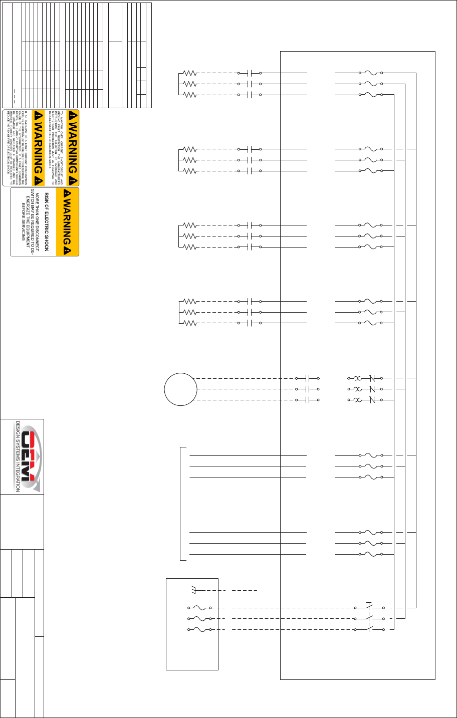
50
SCHEMATICS
PANEL, CONTROL MAIN POWER X600
3500 N. St Paul Ave. Sioux Falls, SD 57104
PH: 605.338.9982
TOLERANCE +1.00"/ -0.00"
PROPRIETARY AND CONFIDENTIAL
THE IN FORMATION CONTAINED IN
THIS DRAWING IS THE SOLE
PROPERTY OF DAKOTA FLUID
POW ER . A NY REPRO DUCTION IN
PART OR A S A WHOLE WITHOUT
THE WRITTEN PERMISSI ON OF
DAKOTA FLUID PO WER IS
PROHIBITED.
JMA
11-Jun-2019
ISSUED
DRAWN
WIRE TYPE GXL or SXL
LOCATION
120
TITL E
600435
1 OF 3
DRAWING NO
SHEET
MMP1
Overload Setting: 8.7A
L1
L2 L3
T1
T2 T3
BLO WE R
480 VAC
7.6 FLA
L1
L2 L3
T1
T2 T3
MC5
L1
L2 L3
T1
T2 T3
MC3
L1
L2 L3
T1
T2 T3
MC4
HEATER-1
480 VAC
12.0 FLA
HEATER-2
480 VAC
12.0 FLA
HEATER-3
480 VAC
12.0 FLA
HEATER-4
480 VAC
12.0 FLA
INCOMING POWER CIRCUIT
Tightening Tor qu e:
31.5IN-LB
Tightening Torqu e:
31.5IN-LB
Tightening Torqu e:
31.5IN-LB
Tightening Torqu e:
31.5IN-LB
DSC1
600VAC/ 100A
DISCONN ECT
POWER CIRCUIT
F6
R ati ng : 600Vac/0.1A
Type: CC-F a s t A c ti n g
L1
L1
L2
L2
L3
L3
10AWG BLACK
14AWG BLACK
GND
L1 L2 L3
L1 L2 L3
Tightening Torqu e:
35.4 IN-LB (8-2AWG)
LINE PROTECTION PROVIDED IN FIELD
F5
R ati ng : 600Vac/15A
Type: CC-F a s t A c ti n g
F4
R ati ng : 600Vac/25A
Type: CC-F a s t A c ti n g
L1
L1
L2
L2
L3
L3
10AWG BLACK
10AWG BLACK
F3
R ati ng : 600Vac/25A
Type: CC-F a s t A c ti n g
L1
L1
L2
L2
L3
L3
10AWG BLACK
10AWG BLACK
10AWG BLACK
F2
R ati ng : 600Vac/25A
Type: CC-F a s t A c ti n g
L1
L1
L2
L2
L3
L3
10AWG BLACK
10AWG BLACK
10AWG BLACK
L1
L2 L3
T1
T2 T3
MC2
F1
R ati ng : 600Vac/25A
Type: CC-F a s t A c ti n g
L1
L1
L2
L2
L3
L3
10AWG BLACK
10AWG BLACK
10AWG BLACK
L1
L2 L3
T1
T2 T3
MC1
14AWG BLACK
14AWG BL ACK
MANUFACTURER MAX V OL TAGE PHASE FLA
HZ
6073.1A3DAKOTA FLU ID POWER 480V AC
LAR G ES T M O TOR F LA SHORT CIRC UIT CURRENT RATI NG
7.6A 5 kVA
POWER SPECIFICATIONS
ENCL OSUR E TYPE
EQUIVALENT CONDUIT HUBS AND/OR
FITTINGS MUST BE USED TO MAINTAIN
ENVIRONMENTAL RATING
1
WIRE & CAB LE SPECIFICATIONS
DE S CRI PTION CO LOR SIZE TYPE
CLASS K
MTW
MTW
MTW
MTW
MTW
MTW
MTW
10 AWG
14 AWG
14 AWG
14 AWG
18 AWG
18 AWG
18 AWG
14 AWG
BL AC K
BL AC K
BL AC K
RED
RED
BL UE
BL AC K
GREEN
MC(1-4) BR ANC H
MMP1 BR ANC H
F(5-6) BR ANC H
12VDC INCOMING
12VDC CONTROL
24VDC CONTROL
0VDC CONTR OL
CHASSIS GROUND
F US E C H ART
DE S CRI PTION V OL TA G E SIZE TYPE
J (T)
CC (F)
CC (F)
CC (F)
CE R AMI C
CE R AMI C
CE R AMI C
CE R AMI C
80
25A
15A
0.1A
4A
5A
10A
15A
600V AC
600V AC
600V AC
600V AC
125V DC
125V DC
125V DC
125V DC
F0
F(1-4)
F5
F6
F7
F8
F9
F10
NOTE: ALL FIELD W IRING SHALL B E COPPER CONDUCTORS WITH A
75deg TEMPERATURE RATING FIELD WIRE
NOTE: ALL FUSES MUST BE REPLACED WITH A TYPE EQUIVALENT TO
THAT SPECIFIED
L1
L1
L2
L2
L3
L3
14AWG BLACK
14AWG BLACK
14AWG BLACK
14AWG BL ACK
14AWG BLACK
14AWG BLACK
SHEET 2
[LM1]
[PS1]
600VAC/ 150A
3POLE BUS BAR
F0
R ati ng : 600Vac/80A
Type: J Tim e-Delay
L1
L1
L2
L2
L3
L3
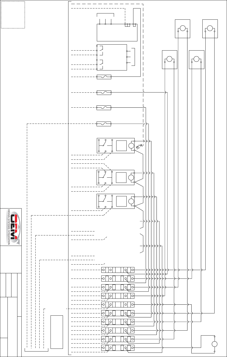
51
PANEL, CONTROL MAIN POWER X600
3500 N. St Paul Ave. Sioux Falls, SD 57104
PH: 605.338.9982
TOLERANCE +1.00"/ -0.00"
PROPRIETARY AND CONFIDENTIAL
THE IN FORMATION CONTAINED IN
THIS DRAWING IS THE SOLE
PROPERTY OF DAKOTA FLUID
POW ER . A NY REPRO DUCTION IN
PART OR A S A WHOLE WITHOUT
THE WRITTEN PERMISSI ON OF
DAKOTA FLUID PO WER IS
PROHIBITED.
JMA
11-Jun-2019
ISSUED
DRAWN
WIRE TYPE GXL or SXL
LOCATION
120
TITL E
600435
2 OF 3
DRAWING NO
SHEET
SHEET 1
LM1
3PH LI NE
MO NIT OR
(SEE DETAIL)
L1 L2 L3
12 11 14
R1
PS1
24VDC/ 5A
POWER
SUP PLY
L3
L2
L1
(+)
(-)
480VAC
INP UT
24VDC
OU TPUT
[F5]
SHEET 1
[F6]
PS1+
PS1-
CONTROL CIRCUIT
LVLE CIRCUIT 1
F7
R ati ng :
125VDC/4A
F7_B
A B
PANEL HARN ESS
CHASSIS HARNE SS
FL1_05
BRANCH CIRCUIT PROTECTION
& DISCONNECT PROVIDED BY
INSTALLER
LVLE CIRCUIT 2
F8
R ati ng :
125VDC/5A
F8_B
A B
F9
R ati ng :
125VDC/10A
F9_B
A B
F10
R ati ng :
125VDC/15A
F10_B
A B
22 21 24
R2
A2A1
R2
FAUL T
12 12
11 11
14 14
LM1_24
LM1_21
LM1_14
LM1_11
R2_11
R2_14
R2_11
R2_14
A2A1
R3
RUN
12 12
11 11
14 14
R3_11
R3_14
A2A1
R1
INTA KE
12 12
11 11
14 14
R1_11
R1_14
A2A1
R5
GATE
CLOSE
12 12
11 11
14 14
R5_11
R5_14
A2A1
R4
GATE
OPEN
12 12
11 11
14 14
R4_11
R4_14
R5_12
12V
0V
12V
0V
12V
0V
12V
0V
12V
0V
12V
0V
12V
0V
12V
0V
12V
0V
12V
0V
1
6
1
6
2
7
2
7
3
8
3
8
4
9
4
9
5
10
5
10
R4_12
0V
0V
0V
0V
0V
12V
12V
12V
6
1
7
2
8
3
9
4
10
5
INCOMING 12VDC
FL1_04
FL1_03
FL1_02
FL1_01
A2
A1
MC1
A2
A1
MC2
A2
A1
MC3
A2
A1
MC4
HEATER 1
MC5
A2A1
BLO WE R
HEATER 3
HEATER 2
HEATER 4
JUMPER JUMPER JUMPER JUMPER
0V
0V
0V
0V
0V
12V
12V
12V
6
1
7
2
8
3
9
4
10
5
F7_A
F8_A
F9_A
F10_A
R1_A1
R2_A1
R3_A1
R4_A1
R5_A1
MC1_A1
MC1_A2
MC2_A1
MC2_A2
MC3_A1
MC3_A2
MC4_A1
MC4_A2
MC5_A1
MC5_A2
DETAIL
LM1 – DIAL SETTINGS
VO LTAGE: 480
>U: 20%
<U: 20%
Tt1: 2.8
Tt2: 2.8
REMOVED
REMOVED
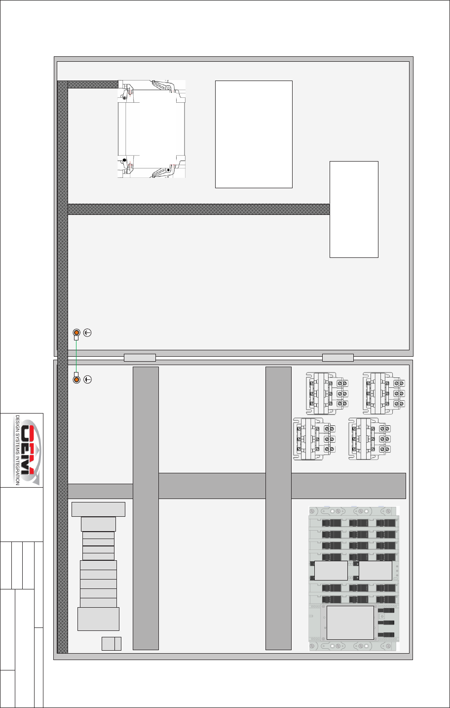
52
PANEL, CONTROL MAIN POWER X600
3500 N. St Paul Ave. Sioux Falls, SD 57104
PH: 605.338.9982
TOLERANCE +1.00"/ -0.00"
PROPRIETARY AND CONFIDENTIAL
THE IN FORMATION CONTAINED IN
THIS DRAWING IS THE SOLE
PROPERTY OF DAKOTA FLUID
POW ER . A NY REPRO DUCTION IN
PART OR A S A WHOLE WITHOUT
THE WRITTEN PERMISSI ON OF
DAKOTA FLUID PO WER IS
PROHIBITED.
JMA
11-Jun-2019
ISSUED
DRAWN
WIRE TYPE GXL or SXL
LOCATION
120
TITL E
600435
3 OF 3
DRAWING NO
SHEET
LAYOUT
PS1
WIRE WAY
DC COMPONENT
ASSEMBLY
WIRE WAY
WIRE WAY
WIRE WAY
LM1
F10F9F8F7 R1 R2 R3 R4 R5
TERMINAL
BLOCKS
GND
DSC1
F6F5F4F3F2F1
MMP1
MC5
MC4
MC3
MC1
MC2
WIRE WAY
HMI
PRINT POCKET
PANEL HARNESS
ENCLOSURE: 36x30x12" TYPE 4
SUB-PANEL: GALVANIZED STEEL
DOOR SUB-PANEL
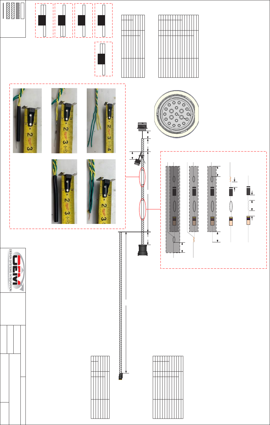
54
1/4"
P04
INTAKE VALVE
HAR NE SS, DEUTZ ADAPTER X600
3500 N. St Paul Ave. Sioux Falls, SD 57104
PH: 605.338.9982
TOLERANCE +1.00"/ -0.00"
PROPRIETARY AND CONFIDENTIAL
THE IN FORMATION CONTAINED IN
THIS DRAWING IS THE SOLE
PROPERTY OF DAKOTA FLUID
POW ER . A NY REPRO DUCTION IN
PART OR A S A WHOLE WITHOUT
THE WRITTEN PERMISSI ON OF
DAKOTA FLUID PO WER IS
PROHIBITED.
JMA
15-Apr-20 19
ISSUED
DRAWN
WIRE TYPE GXL or SXL
LOCATION
120
TITL E
600438
1 OF 1
DRAWING NO
SHEET
BRAID
NO BRAID
SPL##
SPL ICE
HEAT SHRINK
SLEEVE
P03
CHASSIS
ITEM QT Y PA R T N UMBE R DESCRI PTION
SOCKET
WEDGELO CK
2
1
LA2702000
W2S-P012
20-16AWG
2P SOCKET
IDENTITY PLUG DESCRI PTION
P04 DT06-2S-P012 INTAKE VALVE
PIN CO LOR SIZE DE S CRI PTION
LO CA TION
1
2
BL K
WHT
INTK_V AL VE_GND
INTK_V AL VE_S IGNAL
P03_08
P03_07
ITEM QT Y PA R T N UMBE R DESCRI PTION
PIN
PIN
CAVITY PL UG
CAVITY PL UG
7
2
10
2
LA2701000
LA2903200
LA2700500
LA2608000
20-16AWG
S I ZE 12
RED
WHITE
IDENTITY PLUG DESCRI PTION
P01 LA 2400200 ENGINE
PIN CO LOR SIZE DE S CRI PTION
LO CA TION
A
B
C
D
F
P
R
V
X
GN/TP
RED
YE/TP
BL K
WHT
WHT
WHT
YE/TP
GN/TP
DIAG_J1939_LO
BATT_PWR
DIAG_J1939_HI
BATT_GND
S TAR T
ALT_EXCITE
IGNITION
J1939_HI
J1939_LO
SPL_05
P02_A
SPL_04
P02_B
P03_04
SPL_02
SPL_03
P03_05
P03_06
14
14
P01
ENGINE
P02
DIAG. PLUG
136"
30"2"
ITEM QT Y PA R T N UMBE R DESCRI PTION
PIN
CAVITY PLUG
WEDGELO CK
6
6
1
LA2701000
LA2700500
LA6412000
20-16AWG
RED
12P, REC PT
IDENTITY PL UG DE S CRI PTION
P03 DT04-12PA-CE02 CHASSIS
3
4
5
6
7
8
WHT
WHT
YE/TP
GN/TP
WHT
BL K
IGNITION
S TAR T
J1939_HI
J1939_LO
INTK_V AL VE_S IGNAL
INTK_V AL VE_GND
SPL_03
P01_F
P01_V
P01_X
P04_02
P04_01
PIN CO LOR SIZE DE S CRI PTION
LO CA TION
ITEM QT Y PA R T N UMBE R DESCRI PTION
SOCKET
CAVITY PL UG
4
8
192900-0634
192991-0018
26-14AWG
SIGNAL
IDENTITY PLUG DESCRI PTION
P02 192900-0313 DIAG. PLU G
PIN CO LOR SIZE DE S CRI PTION
LO CA TION
A
B
G
H
RED
BL K
GN/TP
YE/TP
BATT_PWR
BATT_GND
DIAG_J1939_LO
DIAG_J1939_HI
P01_B
P01_D
SPL_05
SPL_04
14
14
3"
2"
3"
FRONT VIEW
C
D
E
F
G
J
K
L
M
N
P
R
S
T
U
V
W
DIODE RES ISTOR
SPL_01
SPL01-02-03
SPL_01
STE P 1
1/4"
1/2"
SPL_01
STE P 2
1/4"
SPL_02
P01_P
SPL_01
STE P 3
1/2"
SPL_02
P01_P
1/2"
SPL_01
STE P 4
SPL_02
P01_P
SPL_03
P01_R
P03_03
SPL_01
STE P 5
SPL_02
P01_P
SPL_03
P01_R
P03_03
1/2"
PN: 1N4001-E3/54 PN: PR03000204709JAC00
SPL04-05
COMPONENTS
STE P 1
STE P 4
STE P 2 STE P 5
STE P 3
P01_P DIODE
SPL_02
ALT_EXCITE
RESISTOR P01_R
P03_03SPL_03
IGNITION
P01_A
P02_G
RES ISTOR
SPL_05
DIAG J19 39 LO
P01_C
P02_H
RES ISTOR
SPL_04
DIAG J19 39 HI
ZIP-TIE
NOTES:
Wi re s hal l be 18 Awg unless otherwise specified.
DEUTZ ADAPTER HARNESS

1-888-757-3545
1-320-759-1583
WWW.THAWZALL.COM
2736 Latoka Lane SW, Unit B
Alexandria,MN 56308
USA
