Baseband Signal Processing Framework for the
OsmocomBB GSM Protocol Stack
Harald Kr
¨
oll, Christian Benkeser, Stefan Zwicky, Benjamin Weber, Qiuting Huang
Integrated Systems Laboratory
ETH Zurich, 8092 Zurich, Switzerland
e-mail:
{kroell,benkeser,zwicky,huang}@iis.ee.ethz.ch
Abstract—The open source GSM protocol stack of the Os-
mocomBB project offers a versatile development environment
regarding the data link and network layer. There is no solution
available for developing physical layer baseband algorithms in
combination with the data link and network layer. In this paper,
a baseband development framework architecture with a suitable
interface to the protocol stack of OsmocomBB is presented.
With the proposed framework a complete GSM protocol stack
can be run and baseband algorithms can be evaluated in a
closed system. It closes the gap between physical layer signal
processing implementations in Matlab and the upper layers of
the Osmocombb GSM protocol stack. The functionality of the
system is verified with a testbed comprising a base station and
a receiver board with RF transceiver and FPGA.
I. INTRODUCTION
Recently, the open source community has discovered the
GSM protocol as an interesting exploration area, mainly for
security aspects. Among the various successful attempts of
open source implementation of several parts of the GSM
network, the community behind the Open Source Mobile
Communication Baseband (OsmocomBB [1]) project has im-
plemented rather complete versions of the data link layer (L2),
and the network layer (L3) of the mobile station (MS) side.
The physical layer (L1) is running partially on a host computer
and partially on hardware of a MS.
Unfortunately, hardware support for L1 is limited: reverse
engineered legacy phones with modified firmware are mainly
used for running OsmocomBB software. Access below the
DSP application interface (API) can hardly be achieved, which
limits the scope of new applications and implementations.
Important tasks in digital baseband domain, such as channel
equalization or decoding, are mostly implemented on the DSP,
and therefore not accessible for further investigation. This
deficiency restricts using OsmocomBB for (research) activities
on the physical layer, which includes analog and digital front-
end, baseband signal processing and L1 control functionality.
The signal processing, hardware development, and commu-
nication technology community has strong interest in an ex-
pandable baseband development framework with an interface
to L2 and above of the GSM protocol stack. OsmocomBB’s
L1CTL protocol between L1 and L2 is well defined, but there
is no development environment available in an ubiquitous
scientific computing language such as Matlab or GNU/Octave,
which can be connected to L1CTL. A framework with an
interface of this type simplifies the validation of the function-
ality of baseband implementations towards higher layers in
a closed system without expensive measurement equipment.
Baseband engineers could use OsmocomBB during the design
process and during testing signal processing blocks that require
interaction with L2/L3.
Contribution: In this paper, a Matlab-based physical layer
development framework architecture with an appropriate in-
terface to the L2/L3 implementation of OsmocomBB is pre-
sented. The framework contains digital baseband signal pro-
cessing with corresponding L1 controller and time processing
unit (TPU), as required for GSM receivers. The different
signal processing blocks are partitioned into so called primitive
functions, which carry out essential tasks like signal filtering,
symbol detection, parameter estimation, bit scrambling, and
decoding. The functionality of the presented framework and
interface architecture is verified on a testbed.
Outline: The paper is organized as follows. In Section II
an overview on mobile phone architecture is given, and the
need for crossing the boundary between L1 and L2/L3 is
substantiated. An interface that connects OsmocomBB with a
physical layer Matlab implementation is presented in Section
III. The Matlab framework architecture is explained in Section
IV. The testbed setup is described in Section V and Section
VI concludes the paper.
II. T
HE MISSING LINK
The protocol stack for GSM is a layered architecture that
is based on the concepts of the ISO Open Systems Intercon-
nection (OSI) model with 7 abstraction layers. The layered
structure allows the distribution of work to specialists that
can focus on a specific layer without having to consider the
multitude of problems and issues that occur in the remaining
6 layers. In particular, baseband signal processing algorithms
and architectures for the physical layer can be developed
by neglecting L2/L3 procedure or operations of even higher
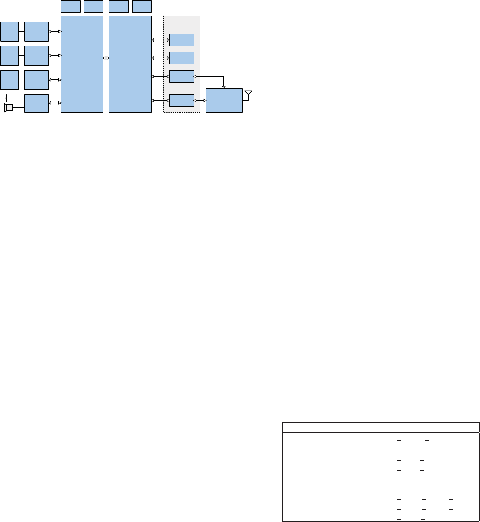
layers. The separation of layers in the GSM standard has led
to the classical partitioning of hardware in mobile phones, as
depicted in Figure 1.
Proceedings of SDR'12-WInnComm-Europe, 27-29 June 2012
©2012 The Software Defined Radio Forum, Inc.-All Rights Reserved 127
!
"
#
$%
#
$%
#
$%$
$
$
$%&'
&'
Fig. 1. A common GSM MS architecture. The PHY is distributed over a
DSP and hardware accelerators [2].
Digital baseband signal processing tasks with low and
medium computational complexity are typically executed on
the Baseband Processor, a power-efficient Digital Signal Pro-
cessor (DSP) optimized for mobile applications. The most
complex parts of the digital baseband signal processing are
usually directly mapped to dedicated hardware accelerator
blocks, in order to achieve the required performance (e.g., bit
error rate, throughput) at reasonably low power consumption.
RLC/MAC layer procedures instead are suitable for an in-
tegration in software, because computational complexity is
fairly low and high flexibility is required. Therefore, these
tasks are typically realized on a reduced instruction set (RISC)
microprocessor, the System Processor, which is connected to
the physical layer implementation via DSP’s API.
Although the strict separation of layers simplifies indepen-
dent development and integration of the specific layers, it
impedes optimizations and applications that require crossing
the layer boundaries. For example, hybrid ARQ which is a
key feature of modern mobile communication standards to
enable high average throughput requires interaction between
RLC/MAC layer and channel decoding in the physical layer.
The hybrid ARQ technique specified for GSM/EDGE [3] is
called Incremental Redundancy (IR). IR manages the storage
of erroneously received data packets, and the combination
of the stored data with re-transmissions of the same data
packet. The combination of the received data packet with
previously received and stored data significantly increases the
probability of correct decoding
1
, and therefore the average data
throughput. Channel decoding is a computationally expensive
baseband signal processing task in the physical layer, whereas
the organization and controlling of re-transmissions, and the
memory management of the stored data blocks is a proce-
dure, that is typically controlled by RLC/MAC layer (see for
example [2]). Therefore, in order to simulate the entire IR
functionality, in order to evaluate average receiver throughput
(with IR enabled) accurately, and in order to optimize IR im-
plementations, being able to operate across the layer boundary
between physical layer and RLC/MAC layer is desired from
designer’s point of view.
1
Different (exclusive and non-exclusive) puncturing schemes are usually
used, in order to increase the information gain with each re-transmission.
Refer to, e.g., [4] for further details.
More than that, having access from higher layers to the
physical layer and vice versa renders new applications pos-
sible. Physical layer procedures, intermediate results of base-
band signal processing blocks, or simply raw baseband sam-
ples can be be monitored from higher layers, which simplifies
debugging and enables new visualization opportunities of
physical layer operations. New applications that require inter-
action between physical layer and higher layers are possible,
such as user cooperation. In an exemplary user cooperation
scenario, several mobile devices M
i
support a mobile device
M
0
by acting as it’s remote antennas. Raw received baseband
samples of the mobile devices M
i
are forwarded from their
physical layer to their application layer. From there, an app
organizes the transmission of these samples to M
0
via an ad-
hoc radio technology, where the samples are combined in the
physical layer. Various combining schemes (e.g., [5]) can be
applied in order to improve the probability of correct decoding.
We conclude that there is a need to have access to the
physical layer in mobile phones, and to be able to model
physical layer functions in combination with higher layers.
In the following, we describe our approach of interfacing
OsmocomBB with a physical layer framework.
III. T
HE INTERFACE BETWEEN L1 AND L2
The GSM specifications do not foresee a detailed protocol
for the communication between L1 and L2. The GSM stan-
dard [6] defines basic messages
2
for the communication with
the data link layer and the RLC/MAC layer. They are sub-
divided into request (REQ), confirm (CONF) and indication
(IND) message types. The messages of OsmocomBB’s L1CTL
protocol are inspired from these message types of the GSM
standard. A set of examples for L1CTL messages is given in
Table I.
TABLE I
L1CTL
MESSAGE EXAMPLES
Functionality L1CTL messages
Reset PHY L1CTL RESET REQ
L1CTL RESET CONF
Synchronization L1CTL FBSB REQ
L1CTL FBSB CONF
Power Measurement L1CTL PM REQ
L1CTL PM CONF
Control Channel Mode L1CTL CCCH MODE REQ
L1CTL CCCH MODE CONF
Data indication L1CTL DA T A IND
The default OsmocomBB interface implementation between
L1 and L2, called osmocon, uses a serial link with HDLC
protocol [7] to load the firmware into the phone’s memory.
Using L1CTL messages, this firmware communicates via
osmocon with a Unix domain Socket as implemented on
the OsmocomBB side for the connection to L2/L3 running
on the host computer. In order to be able to replace the
firmware with a physical layer Matlab implementation, the
2
The basic messages are called primitives of the physical layer in the GSM
specifications [6].
128
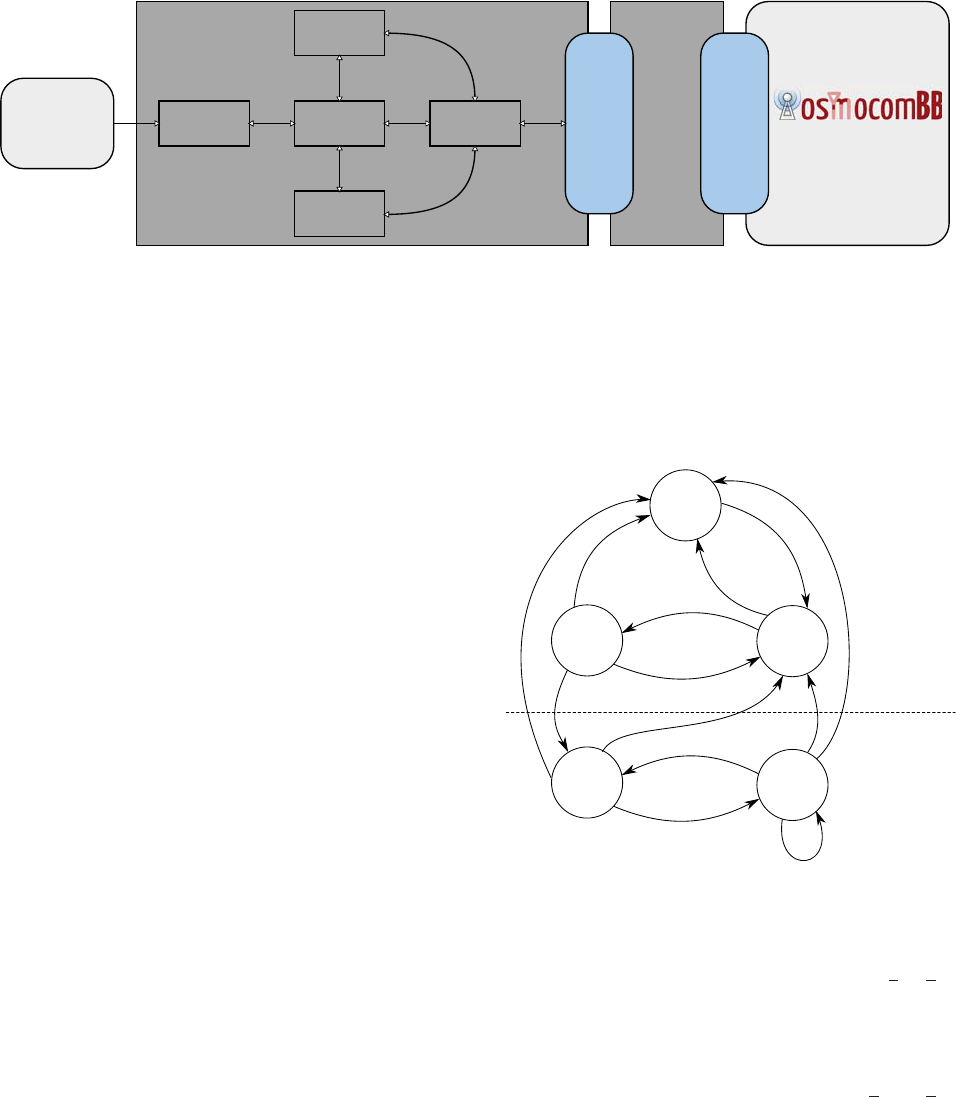
Fig. 2. Architecture of interface and framework between physical layer and mobile.
Unix domain socket needs to be connected with Matlab.
Unfortunately, Matlab does not directly support Unix domain
sockets, so an interface written in C is required for the
socket communication. One solution would be to have such
an interface embedded in a MEX function, such that it could
be called inside a Matlab script. means of Matlab engine
function calls. However, both MEX function calls and Matlab
engine function calls are blocking, what prohibits parallel
execution L1CTL protocol handling and baseband processing.
Instead, the interface (herein referred to as phyconnect) for
the proposed physical layer development framework connects
the Unix domain socket to Matlab via memory mapped file as
depicted in Figure 2.
In order to prevent accidental overwriting of data in the
memory, a handshake protocol has been implemented. Thus,
phyconnect sending data to Matlab waits first for Matlab to
retrieve any data in the memory mapped file. By the same
token, Matlab waits for the phyconnect process to retrieve data
first before overwriting it. The memory mapped file has a total
length of 880 bytes, which is used to build an array of 220
entries of 32 bit unsigned integers. There are entries for all
information that needs to be accessible by L1, phyconnect and
L2, such as GSM counters, L1CTL message properties, pay-
load, and necessary information for the handshake protocol.
We conclude that the proposed interface is a flexible solution to
connect RLC/MAC layer of OsmocomBB with physical layer
implementations in Matlab. In the following section we present
our framework architecture that uses phyconnect to enable the
simulation of our L1 Matlab realization in combination with
the L2/L3 software, the mobile application, of OsmocomBB.
IV. F
RAMEWORK ARCHITECTURE
Our baseband signal processing framework is shown in
Figure 2. It comprises a GSM physical layer implementation,
referred to as phydev, and the interface phyconnect to connect
the mobile application of OsmocomBB, as explained in the
previous section. Phydev is a Matlab realization of the phys-
ical baseband receiver that is typically implemented on the
baseband processor assisted by accelerator blocks in dedicated
hardware (cf., Figure 1). The main components of phydev are
the TPU, the L1 controller, the primitive functions, and the
handles, which will be explained in the following.
A. Layer 1 controller
The layer 1 controller builds the connection between the in-
terface towards L2/L3 and the actual physical layer processing
units. It implements the PHY finite state machine of a MS for
GSM, as specified in [6] and shown in Figure 3.
!
!
"#
$"
"""#
$"
Fig. 3. PHY finite state machine with the states for the idle and dedicated
mode [6].
After switching on the MS the state machine starts from the
NULL state. From this, after having received a L1
PM REQ
message, the cell search procedure starts. First, the power
levels of all possible GSM carriers are measured and reported
to higher layers in the searching BCH state, in order to find the
beacon carrier. Next, synchronization in time and frequency
is performed after having received a L1CTL
FBSB REQ
message. In the BCH state the system information carried on
the logical BCCH channel is extracted and reported to L2/L3.
At this point the GSM state camping on any cell is achieved.
Note that the states of dedicated mode (c.f. Figure 3) are not
implemented in our framework so far.
The controller receives L1CTL messages from the interface
via the memory mapped file. Subsequently, the messages
get processed and multiplexed to a corresponding handle.
The handle schedules the execution of primitive functions
129
if applicable and creates confirmation (CONF) or indication
(IND) messages for the layer above.
During the searching BCH state the involved handles oper-
ate on consecutive samples, as there is no information about
the GSM timing available. This streaming based operation
is applied for the synchronization procedure and the power
measurements (c.f., the example shown in Figure 5). After
synchronization in frequency and time (in BCH state) the
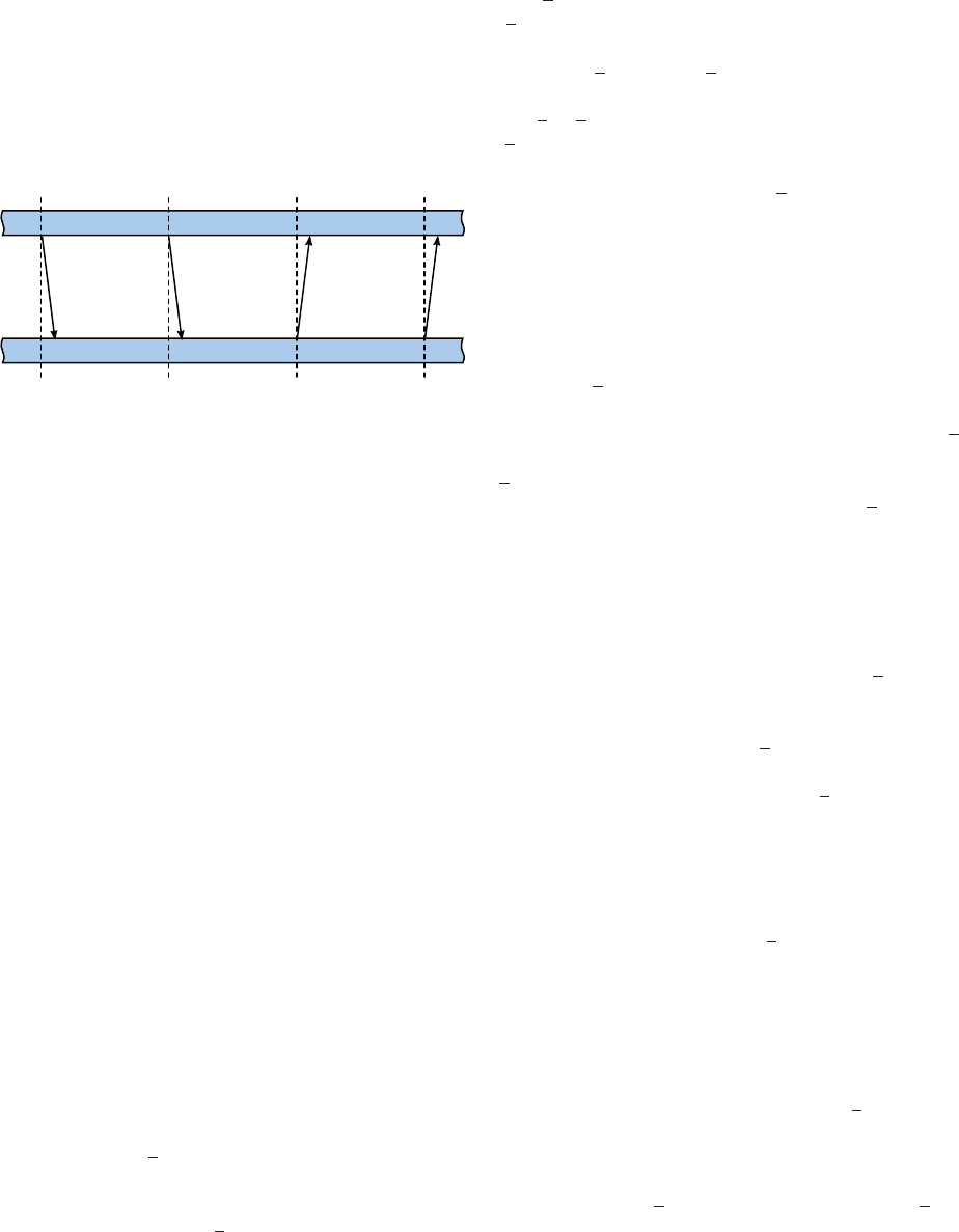
execution is frame based as depicted in Figure 4.
Fig. 4. Frame based execution on the physical layer in dedicated mode.
The complex signal processing algorithms do not run fast
enough in Matlab to be executed in real time as required for
the physical layer implementation. As timing is essential in
GSM, we have implemented a TPU in phydev that emulates the
four specified GSM timebase counters. This TPU allows the
simulation of the timing between execution of primitives, L1
controller procedures, and communication with higher layers.
More specifically, handles are called according to the TPU
counter states. For each call, the counters are increased by
the number of samples the corresponding primitive function
processes. The corresponding L1CTL messages are generated
and transmitted to OsmocomBB.
B. Primitive Functions
To ensure that the execution of operations on I/Q samples is
carried out at the right time, functions which provide a result
after a predefined number of samples are necessary. To this
end, functions that process a fixed number of I/Q samples are
implemented in phydev, referred to as primitive functions. The
number of samples to be processed and other primitive-specific
parameters are input arguments of the functions. The output of
a primitive function is processed by the corresponding handle
and forwarded to the L1 controller. The signal processing
blocks represent entities as typically implemented as accel-
erator blocks or on the baseband processor, such as channel
equalization, digital filtering stages or correlations. In addition
to the primitive functions, auxiliary functions (auxiliaries) for
common RF transceiver operations like RF power control or
oscillator tuning (DCXO
tune) are provided.
In the following the main primitives and related signal
processing blocks are explained in detail.
1) Power Measurements (PM
meas): Mobile stations for
GSM have to measure the received signal power on all possible
GSM carriers after power on, as well as the received signal
power of the beacon carrier transmitted by surrounding base
stations during operation. These tasks can be performed with
the PM
meas primitive function. The input arguments of
PM
meas are the number of samples to be processed and
the absolute radio frequency channel number (ARFCN). The
output of PM
meas (RMS LEVEL) is the RMS power in
dBm computed over the amount of processed samples. The
L1CTL
PM REQ-handle maps the result to an integer value
RX
LEV and computes the running average according to the
GSM specifications in [8].
2) Frequency burst detection (FB
det): The first synchro-
nization step after the initial power measurements in the
cell search procedure is the detection of the frequency burst
(FB) on the beacon carrier, which is broadcast approx. every
47 ms. The FB is transmitted as a complex sinusoid, what
enables a variety of detection strategies at receiver side. In
this framework FB detection is performed according to [9],
where the predictability of a complex sinusoid is exploited. By
calling the FB
det primitive function, this detection algorithm
is computed on the samples to be processed given as input
arguments. The instance of time of the last successful FB
det
primitive call gives a coarse timing estimate which is used in
SB
synch.
3) Carrier frequency offset estimation (FB
est): Carrier
frequency estimation is crucial during cell search, but also
during normal operation. In our framework the carrier fre-
quency offset is estimated from the FB’s complex sinusoid by
using the T&F estimator from [10], where a correlation based
estimator is used. This approach has a significantly lower
computational complexity when compared to, e.g., costly
periodogram-based estimators. By calling the FB
est primitive
function, this carrier frequency offset estimation algorithm is
executed by processing the number of samples specified as
input arguments. The output of FB
est is the estimated carrier
frequency offset.
4) Synchronization burst detection (SB
synch): After syn-
chronization in frequency has been achieved, timing synchro-
nization needs to be performed. In GSM the detection of the
synchronization burst (SB) which is also broadcast on the
beacon carrier allows precise synchronization in time. A coarse
timing estimate is already provided by the FB detection and
given as input argument to the SB
synch primitive function.
Thus, the SB detection needs only to be performed on the
part of the received samples, which has been identified by the
coarse synchronization as SB. Finally, the position of the 64
bit extended training sequence of the SB is detected accurately
by performing a correlation between the received signal and
the known training sequence.
5) Synchronization burst demodulation (SB
demod): Some
of the GSM system information is transmitted on the SB
and needs to be extracted during the cell search procedure.
Demodulation of the symbols on the SB is performed with the
primitive function SB
demod, which is similar to NB demod
for the demodulation of symbols on a normal burst (NB),
which is explained in more detail in the next paragraph.
Different training sequence lengths of SB and NB require two
separate primitive functions.
130
6) Normal burst Demodulation (NB demod): The primitive
function NB
demod demodulates traffic and control data on
normal bursts (NB). To this end, channel estimation, channel
equalization and symbol demodulation have to be performed.
In our implementation the channel profile is estimated in
MMSE sense, as described in [11], where the midamble (train-
ing sequence) of each GSM burst is exploited. Channel equal-
ization and symbol demodulation are performed with maxi-
mum likelihood sequence estimation (MLSE) [12], as typically
used in GSM receivers. Input arguments of NB
demod are
the number of samples to be processed, and the demodulated
symbols are output.
Other tasks like interleaving, bit swapping, burst demapping
or channel decoding (with a Viterbi decoder implementation)
are executed by the L1 controller correspondingly.
An exemplary scenario for the processing of a
L1CTL
FBSB REQ message is depicted in Figure 5.
As can be seen in Figure 3, successful processing of
L1CTL
FBSB REQ is required to reach the BCH state in
the PHY functional state machine. After all the primitives
and auxiliaries are called by the L1CTL handle, it composes
a L1CTL
FBSB CONF message and sends it back to the
controller.
!
"#
$%
!$
&
!
'(!
Fig. 5. Processing of L1CTL FBSB REQ message.
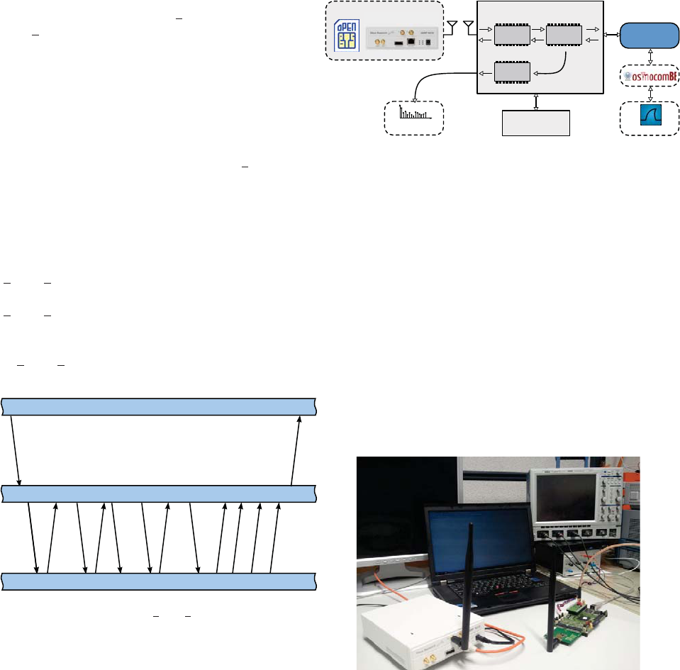
V. T ESTBED SETUP
In order to feed our baseband signal processing framework
with real-world data, a testbed setup, shown in Figure 6, has
been developed. It consists of a GSM base station (BTS)
emulator, a receiver board, a computer and a spectrum analyzer
for debugging purposes.
The BTS emulator has been realized with OpenBTS [13]
(an open source BTS software) and GNU radio software
running on a computer, and a USRP
3
board with antenna
to transmit the signal over the air. On the receiver board an
antenna is connected to a state-of-the-art RF transceiver with
ADC
4
, which converts the RF signal to baseband and digital
domain. The oversampled signal is fed into an FPGA on the
3
Universal Software Radio Peripheral, from Ettus Research.
4
IRIS305 RF Transceiver from ACP Semiconductors, Zollikon, Switzer-
land.
!
"#$
%
Fig. 6. Testbed Architecture with involved components.
receiver board, where decimation filtering and downsampling
is performed with our digital front-end (DFE) implementation.
A DAC on the receiver board allows to convert this signal
back to analog domain and visualize the signal on a spectrum
analyzer, which enables us to quickly identify problems on the
receiver board. From the FPGA the DFE output signal is sent
to a computer, where our framework processes the received
samples and communicates with the mobile application of Os-
mocomBB, as described in the previous sections. The mobile
application encapsulates the down-link data in UDP packets,
which are forwarded for visualization to the Wireshark [14]
protocol analyzer running on the same computer. A picture of
the testbed setup is shown in Figure 7.
Fig. 7. Testbed setup with USRP N200 and receiver board.
The testbed setup has been used to verify the functionality
of our framework in combination with L2/L3 of OsmocomBB
by performing the initial cell search procedure in GSM
(c.f. Section IV-A). To this end, the BTS emulator transmits
a standard-compliant GSM beacon channel. The signal is
received and processed on the receiver board as previously
described, and corresponding I/Q samples are loaded from the
receiver board into phydev, where the beacon carrier is found,
and synchronization in time and frequency is achieved. The
GSM system information (SI) broadcast on the beacon carrier
is correctly extracted and propagated through OsmocomBB to
Wireshark, where the SI messages are displayed.
131
VI. CONCLUSION
The OsmocomBB project provides an excellent open-source
software implementation of the data link layer and the network
layer of GSM. Unfortunately, the physical layer is not cov-
ered by OsmocomBB and hardware support is limited. Our
proposed baseband signal processing framework shows how
the physical layer can be realized in Matlab and connected to
OsmocomBB with a dedicated interface. The verification of
the framework and interface with the developed testbed setup
proofs the feasibility of the proposed approach.
R
EFERENCES
[1] “OsmocomBB, http://bb.osmocom.org, April 2012.”
[2] L. Chang and Y. Wang, “EDGE incremental redundancy memory
structure and memory management,” Jul. 23 2009, uS Patent App.
12/507,835.
[3] 3GPP TR 44.004: General Packet Radio Service (GPRS); Mobile Station
(MS) - Base Station System (BSS) interface; Radio Link Control /
Medium Access Control (RLC/MAC) protocol, TS 45.060, Rev. 9.0.0,
Dec. 2009.
[4] E. Seurre, P. Savelli, and P. Pietri, EDGE for mobile Internet. Artech
House Publishers, 2003.
[5] B. Djeumou, S. Lasaulce, and A. Klein, “Practical quantize-and-forward
schemes for the frequency division relay channel,” EURASIP Journal on
Wireless Communications and Networking, p. 2, 2007.
[6] 3GPP TR 44.004: GSM/EDGE Layer 1; General requirements,TS
45.004, Rev. 9.0.0, Dec. 2009.
[7] ISO/IEC 13239: Information technology Telecommunications and infor-
mation exchange between systems High-level data link control (HDLC)
procedures, TS 132 394, Rev. 9.0.0, Jul. 2002.
[8] 3GPP TR 45.008: GSM/EDGE Radio Access Network; Radio subsystem
link control, TS 45.008, Rev. 9.0.0, Nov. 2009.
[9] U. Jha, “Acquisition of frequency synchronization for GSM and its
evolution systems,” in Proceedings of IEEE International Conference
on Personal Wireless Communications, 2000, pp. 558–562.
[10] D. Tufts and P. Fiore, “Simple, effective estimation of frequency based
on prony’s method,” in Proceedings of IEEE International Conference
on Acoustics, Speech, and Signal Processing (ICASSP), vol. 5, may
1996, pp. 2801–2804.
[11] E. Yakhnich, “Channel estimation for EGPRS modems,” in Proceedings
of Vehicular Technology Conference, VTC-Spring, vol. 1. IEEE, 2001,
pp. 419–422.
[12] J. Proakis, Digital communications. McGraw-hill, 1987.
[13] “Openbts, http://openbts.sourceforge.net, april 2012.”
[14] A. Orebaugh, G. Ramirez, and J. Burke, Wireshark & Ethereal network
protocol analyzer toolkit. Syngress Media Inc, 2007.
132
