Global System for Mobile Global System for Mobile
(GSM) (GSM)
David Tipper
Associate ProfessorAssociate Professor
Graduate Program of Telecommunications and
Networking
Universit
y
of Pittsbur
g
h
Telcom 2700
1
yg
TelcomTelcom 2700 Slides 52700 Slides 5
Based largely on material from Jochen Schiller, Mobile Communications
2
nd
edition
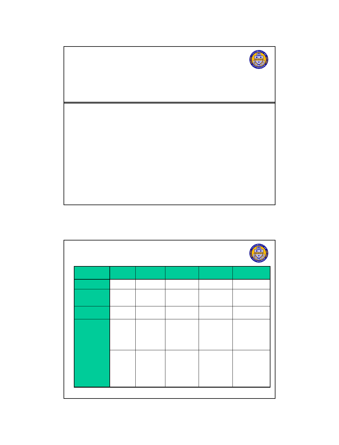
Generations of Cellular Networks
Feature/
Decade
1980s 1990s 1999-2002 2002-2010 2010-2020
Generation First Second 2.5G Third , 3.5G Fourth/Fifth
Keywords
Analog
Digital Voice
Wireless Data
High speed
High Data rate
Keywords
Analog
Digital
Voice
Wireless
Data
High
speed
wireless data
High
Data
rate
,
IP- based, high
mobility
Multiaccess FDMA TDMA
CDMA
TDMA
CDMA
CDMA, OFDMA
Systems AMPS,
NMT
TACS
NTT
C45
NA-TDMA
PDC
GSM
IS-95 (cdma
one)
HSCSD,
GPRS,EDGE
cdma 2000
WCDMA,
UMTS, HSDPA,
HSUPA
Cdma2000 -
EVDO
LTE
Hybrid networks
Telcom 2700
2
Telcom 2700
C45
one)
Incompatibl
e systems
Limited
mobility
Voice Only
Incompatible
systems –
focus still
voice, SMS
low speed
data
Focus on data
service
Max Data rate
171kbps
Data rate
.2-11 Mbps
Data rate
2-54 Mbps

First Generation Systems
Goal: Provide basic voice service to mobile users over
large area
1 G Systems developed late 70
’
s early 80
’
s deployed in
1
G
Systems
developed
late
70 s
early
80 s
,
deployed
in
80’s
Advanced Mobile Phone System (AMPS) - USA
Total Access Communications Systems (TACS) - UK
Nordic Mobile Telephone (NMT) System – Scandanavian
PTTs
C
4
50
-W.
Ge
rm
a
n
y
Telcom 2700
3
C50
Ge a y
NTT System - Nippon Telephone & Telegraph (NTT) – Japan
Incompatible systems using different frequencies!
Have similar characteristics though
First Generation Systems
Characteristics of 1G systems
Use Cellular Concept to provide service to a
g
eo
g
ra
p
hic area
(
i.e. number of small ad
j
acent
ggp ( j
cells to provide coverage)
Frequency Reuse
Handoff/Handover
FDMA/FDD systems
Common Air Interface (CAI) standards only
A
nalo
g
Voice communications usin
g
FM
Telcom 2700
4
gg
Digital Control channels for signalling
Adjustable Mobile Power levels
Macro Cells : 1-40 km radius
Second Generation Cellular Systems
Motivation for 2G Digital Cellular:
Increase System Capacity
Add additional services/features
(
SMS, caller ID, etc..
)
()
Reduce Cost
Improve Security
Interoperability among components/systems (GSM only)
2G Systems
Pacific Digital Cellular orphan technology
North American TDMA (NA
TDMA)
orphan technology
Telcom 2700
5
North
American
TDMA
(NA
-
TDMA)
orphan
technology
Global System for Mobile (GSM)
IS-95 (cdma one)
GSM: History
1982 CEPT establishes Groupe Speciale Mobile
Motivation develop Pan-European mobile network
Support European roaming and interoperability in landline
Increase system capacity
Increase
system
capacity
Provide advanced features
Emphasis on STANDARDIZATION, supplier independence
Low cost infrastructure and terminals
1989 European Telecommunications Standardization Institute (ETSI)
takes over standardization
changes name: Global System for Mobile communication
1990 First Official Commercial launch in Europe
Telcom 2700
7
1990
First
Official
Commercial
launch
in
Europe
1995 GSM Specifications ported to 1900 MHz band
GSM is the most popular 2G technology and still the most popular
technology ~ 70% of phones worldwide are GSM only or GSM
compatible has more users than all other technologies combined

GSM Overview
• FDD/ FDMA/TDMA – channel structure - 200 KHz
channels – each carriers 8 voice channels
• Higher Quality than Analog Systems
Di it l V i 13 3Kb
•
Di
g
it
a
l
V
o
i
ce
13
.
3Kb
ps
• Slow frequency hopping, adaptive equalizer, error
control coding, DTX
• Low power handsets – support sleep mode
• Security with encryption
• Wide roaming capability
•
Subscriber Identity Modules (SIM cards)
Telcom 2700
9
Subscriber
Identity
Modules
(SIM
cards)
• Digital data service
• fax, circuit switched data
• SMS short messaging service
• Additional features : call waiting, voice mail, group calling,
caller id etc.
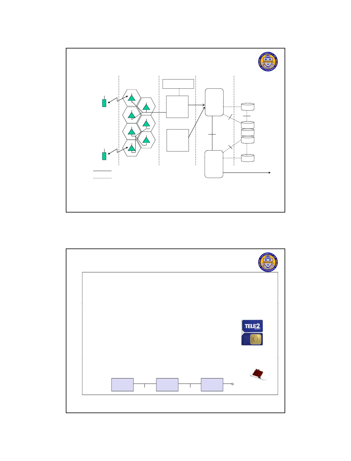
Architecture of the GSM system
GSM is a PLMN (Public Land Mobile Network)
Several providers can setup mobile networks following the GSM
standard within each country
Major components
MS (mobile station)
BTS (base transceiver station) or BS or cell site
BSC (base station controller)
MSC (mobile switching center)
LR (location registers): VLR, HLR
AUC(Authentication database), EIR (Equipment Identity Register)
Subsystems
RSS (radio subsystem): covers all radio aspects
Telcom 2700
10
RSS
(radio
subsystem):
covers
all
radio
aspects
NSS (network and switching subsystem): call forwarding, handoff,
switching, location tracking, etc.
OSS (operation support subsystem): management of the network
Standardized interfaces
Allows provider to mix and match vendor equipment
GSM System Architecture
BTS
BTS
BTS
BTS
BTS BSC
BSC MSC
HLR VLR AUC
PSTN
ISDN
MS
Telcom 2700
11
BTS
OMC
Data
Networks
Operation Support
Subsystem
Network Switching Subsystem
Public NetworksRadio Station Subsystem
MS
Functional Architecture
Radio Subsystem (RSS)
Base Station Subsystem
(BSS)
Network and
Switching
Subsystem (NSS)
Operation
Subsystem
(OSS)
MS
MS
BTS
BTS
BSC
HLR
VLR
AuC
OMC
O
Telcom 2700
12
MS
BTS
BTS
BSC
MSC
EIR
Radio Interface
Interface to
other networks
PSTN etc.
U
m
A
bis
A
GSM System Architecture
B, C, D, E, F
Mobile Application
Protocol Interfaces
Mobile
Switchin
g
OMC - Radio
Base
Si
BTS
BTS
UM
Interface
A-Bis
Interface
A Interface B Interface
VLR
HLR
AUC
EIR
VLR
Mobile
g
Center
(MSC)
S
tat
i
on
Controller
(BSC)
Base
Station
Controller
(BSC)
BTS
BTS
BTS
BTS
BTS
D Interface
F
Interface
C
Interface
E
Interface
Telcom 2700
13
VLR
Switching
Center
(MSC)
Traffic and Signaling
Signaling only
VLR = Visitor Location Register
HLR = Home Location Register
EIR = Equipment Identity Register
AUC = Authentication Center
BTS = Base Transceiver Station
ADC = Admission Data Center
OMC = Operation Maintenance Center
PSTN
Mobile station
Terminal for the use of GSM services
A mobile station (MS) comprises several functional groups
MT (Mobile Terminal):
offers common functions used b
y
all services the MS offers
y
end-point of the radio interface (U
m
)
TA (Terminal Adapter):
terminal adaptation, hides radio specific characteristics
TE (Terminal Equipment):
peripheral device of the MS, offers services to a user
does not contain GSM specific functions
SIM (Subscriber Identity Module):
Telcom 2700
14
personalization of the mobile terminal, stores user parameters (subscriber
number, authentication key, PIN, etc.)
RS
U
m
TE TA MT
Radio Station Subsystem (RSS)
Components
MS (Mobile Station)
BSS (Base Station Subsystem):
U
radio statiion
subsystem
network and switching
subsystem
MS MS
consisting of
BTS (Base Transceiver Station):
antenna + digital radio equipment
BSC (Base Station Controller):
controlling several transceivers, map
radio channels (Um) onto terrestrial
channels A
Interfaces
U
: radio interface
U
m
A
bis
A
BTS
BSC
MSC
BTS
Telcom 2700
15
U
m
:
radio
interface
A
bis
: standardized, open interface with
16 kbit/s user channels
A: standardized, open interface with
64 kbit/s user channels as in wired
telephone network
A
BSS
BTS
BSC
BTS
MSC
Base Transceiver Station and Base Station
Controller
Tasks of a RSS are distributed over BSC and BTS
BTS comprises radio specific functions
BSC is the switchin
g
center for radio channels
g
Functions BTS BSC
Management of radio channels X
Frequency hopping (FH) X X
Management of terrestrial channels X
Mapping of terrestrial onto radio channels X
Channel coding and decoding X
Rate adaptation X X
Encr
yp
tion and decr
yp
tion
X
X
Telcom 2700
16
yp yp
Paging X X
Uplink signal measurements X
Traffic measurement X
Handover management X
GSM Air Interface U
m
Uses Physical FDMA/TDMA/FDD physical
In 900 MHz band: 890-915 MHz Uplink band, 935-960 MHz
Downlink
Radio carrier is a 200kHz channel => 125 pairs of radio channels
Called Absolute Radio Frequency Channel Number (ARFCN)
ARFCN numbers given by f(n) = 890 +.2n MHz for Uplink band n = 0,
…124
Corresponding downlink is f(n) + 45 MHz
Channels and ARFCN slightly different in other frequency bands
A TDMA frame is defined on the radio carrier (8 users per carrier)
C
Telcom 2700
17
C
hannel rate is 270.833 kbps
(RELPC) digital speech 13.3kbps
Two types of logical channels map onto physical channels
Control Channels (call setup, power adjustment, etc..)
Traffic Channels (voice or data) = 22.8kbps = 1 slot in a TDMA frame
935-960 MHz
124 channels (200 kHz)
downlink
890-915 MHz
124 channels (200 kHz)
GSM - TDMA/FDMA
12
3
4
5
6
78
higher GSM frame structures
uplink
time
GSM TDMA frame
4.615 ms
Telcom 2700
18
GSM time-slot (normal burst)
546.5 µs
577 µs
tail user data TrainingS
guard
space
S user data tail
guard
space
3 bits 57 bits 26 bits
57 bits1
13
GSM: FDD Channels
B
S
to
M
S
D
o
wnlink
0 1 2 3 4 5 6 7 0
1.73 ms
BS
to
MS
Downlink
MS to BS Uplink
200 KHz
1 2
5 6 7 0 1 2 3 4 5 6 7
45 MHz
Telcom 2700
19
Frame= 4.62 ms
Uplink and Downlink channels have a 3 slot offset – so that
MS doesn’t have to transmit and receive simultaneously
MS can also take measurements during this offset time and delay
between next frame
GSM Normal Burst
Training sequence is
utilized for seting
4.615 ms
adaptive equalizer
parameters
Guard Period = 30.5
microsecs
Needed to allow for
clock misalignment
and propagation time
of mobiles as
0 1 2 3 4 5 6 7
T
3
Data
57
S
1
Train
26
S
1
Data
57
T
3
Guard
825
Telcom 2700
20
of
mobiles
as
different distances
from BTS
3
57
1
26
1
57
3
8
.
25
577 us
T: tail bits, S:flag, Train: equalizer training sequence
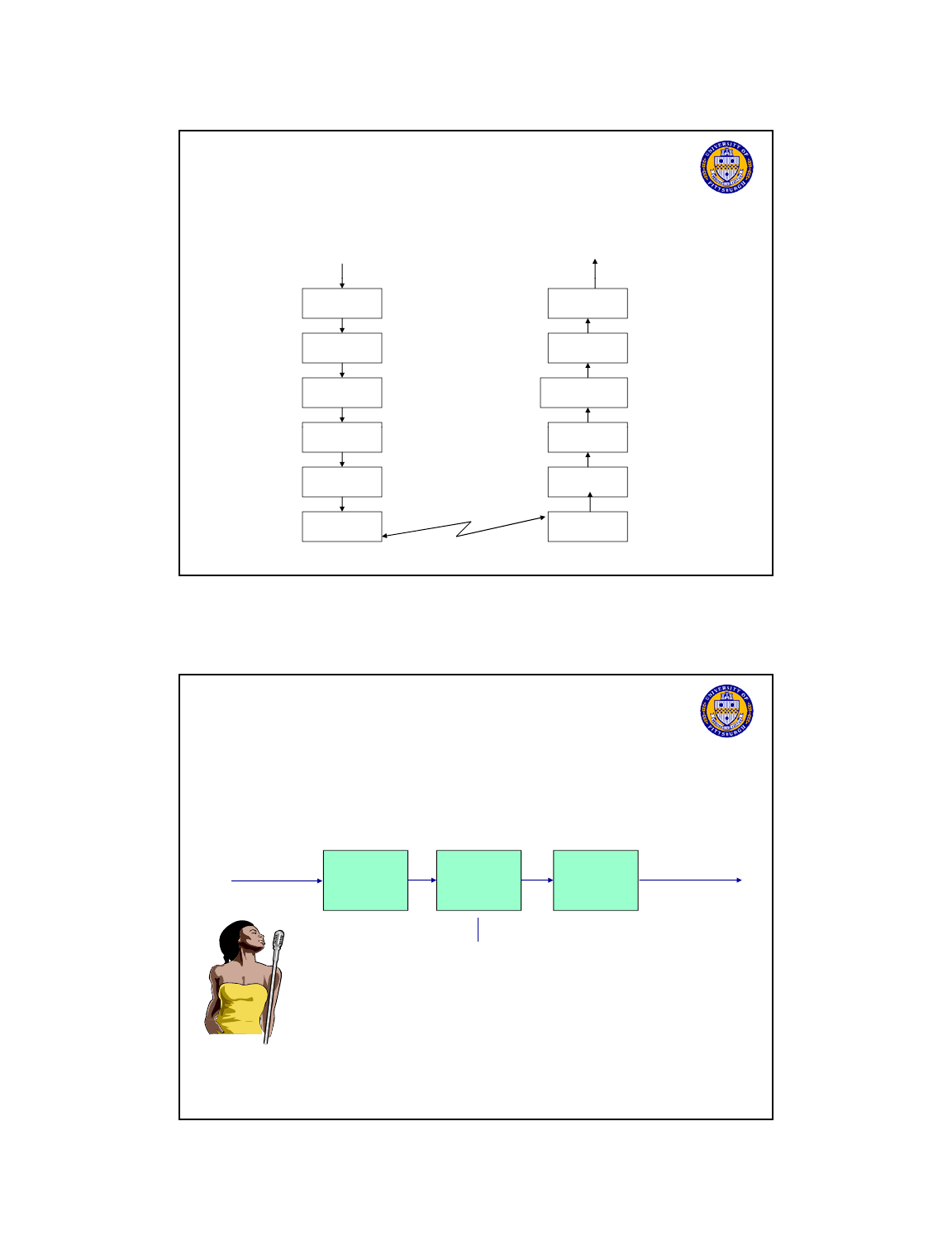
GSM operation from speech Input to Output
Speech
Speech
Digitizing and
source coding
Channel
coding
Interleaving
Burst
Source
decoding
Channel
decoding
De-Interleaving
Burst
Telcom 2700
21
Burst
Formatting
Ciphering
Modulation
Burst
Formatting
De-ciphering
Demodulation
Radio
Channel
GSM Speech Coding
Low-pass
filter
Analog
speech
A/D
RPE-LTP
speech
encoder
Channel
encoder
8000 samples/s,
13 bits/sample
104 kbps
13 kbps
Telcom 2700
22
13
bits/sample
GSM Speech Coding (cont)
Regular pulse excited - long term prediction (RPE-LRP)
speech encoder (RELP speech coder)
RPE-LTP
speech
encoder
160 samples/
20 ms from A/D
(= 2080 bits)
36 LPC bits/20 ms
9 LTP bits/5 ms
47 RPE bits/5 ms
260 bits/20 ms
to channel
encoder
Telcom 2700
23
LPC: linear prediction coding filter
LTP: long term prediction – pitch + input
RPE: Residual Prediction Error:
Error protection for speech signals in GSM
Type Ia
50bits
Type Ib
132bits
Type II
78bits
Parity
check
ClilCd
50bits
132bits
78bits
50 3 132 4
Telcom 2700
24
456 bits per 20ms speech frame
C
onvo
l
ut
i
ona
l
C
o
d
e
Rate ½, constraint length 5
378 78
Interleaving Format
speech
20 ms 20 ms
RPE-LTP encoding
260 260
Channel
encoding
Channel
encoding
Speech
coder
Speech
coder
456 bit
encoding
encoding
456 bit
D
1
D
2
D
3
D
4
D
5
D
6
D
7
D
8
D
1
D
2
D
3
D
4
D
6
D
5
D
7
D
8
1
2345678
Interleaving
Stream of
Timeslots
(only one time slot sent in a frame)
Single frame
Telcom 2700
25
Interleave distance = 8
tail
3
57 bit
26 bit
(training)
11 38.25
data data tail
Guard
57 bit
Out of first 20 msec
Out of second 20 msec
Normal burst
Modulation
• Variation on Frequency Shift Keying (FSK)
• Avoids sudden phase shifts MSK (Minimum Shift Keying)
Bit t t d i t d dd bit th d ti f h
Gaussian
Low Pass
Filter
FM
Transmitter
NRZ Data GMSK Output at RF
•
Bit
s
t
ream separa
t
e
d
i
n
t
o even an
d
o
dd
bit
s,
th
e
d
ura
ti
on o
f
eac
h
bit is doubled
Telcom 2700
26
Depending on the bit values (even, odd) the higher or lower
frequency, original or inverted is chosen
The frequency of one carrier is twice the frequency of the other
Example of MSK
data
even bits
1
11 1000
bit
even 0 1 0 1
odd 0 0 1 1
odd bits
low
frequency
high
frequency
signal h n n h
value --+ +
h: high frequency
n: low frequency
+: original signal
-: inverted signal
Telcom 2700
27
t
MSK
signal
No phase shifts!
GSM Frequency Hopping
Optionally, TDMA is combined with frequency
hopping to address problem of channel fading
TDMA bursts are transmitted in a precalculated
TDMA
bursts
are
transmitted
in
a
precalculated
sequence of different frequencies (algorithm
programmed in mobile station)
If a TDMA burst happens to be in a deep fade,
then next burst most probably will not be
Hel
p
s to make transmission
q
ualit
y
more uniform
Telcom 2700
28
pqy
among all subscribers
Improves frequency resuse
Hops at the frame level – 217 hops/sec
Frequency-hopped signal in GSM
Frame N-1
Frequency
Frame 1
4.615 msec
Frame 2
Frame 3
Frame N
Telcom 2700
29
Time
Frame N+1
GSM Air Interface Specifications Summary
Parameter Specifications
Reverse Channel Frequency
Forward Channel Frequency
935 – 960 MHz
890 – 915 MHz
ARFCN Number
Tx/Rx Frequency Spacing
Tx/Rx Time Slot Spacing
Modulation Data Rate
Frame Period
Users per Frame (Full Rate)
Time slot Period
576.9
s
8
4.615 ms
270.833333 kbps
45 MHz
3 Time slots
0 to 124
Telcom 2700
30
Time
slot
Period
Bit Period
Modulation
ARFCN Channel Spacing
Interleaving (max. delay)
Voice Coder Bit Rate
13.3 kbps
40 ms
200 kHz
GMSK
3.692 s
576.9
s
Notation Name Size (bits) Description
IMSI
International mobile
subscriber identity
15 digits (50 bits) Directory number conforming to international
convention – assigned by operating company
to subscriber
GSM System Identifiers
TMSI
Temporary mobile
subscriber identity
32 bits Assigned by visitor location register to a
subscriber
IMEI
International mobile
equipment identifier
15 digits Assigned by manufacturer to a mobile station
Ki
Authentication Key 128 bits Secret key assigned by the operating
company to a subscriber
Kc
Cipher Key 64 bits Computed by network and mobile station
Telcom 2700
31
-
Mobile Station class mark 32 bits Indicates properties of a mobile station
BSIC
Base Station identity code 6 bits Assigned by operating company to each BTS
-
Training Sequence 26 bits Assigned by operating company to each BTS
LAI
Location Area Identity 40 bits Assigned by operating company to each BTS
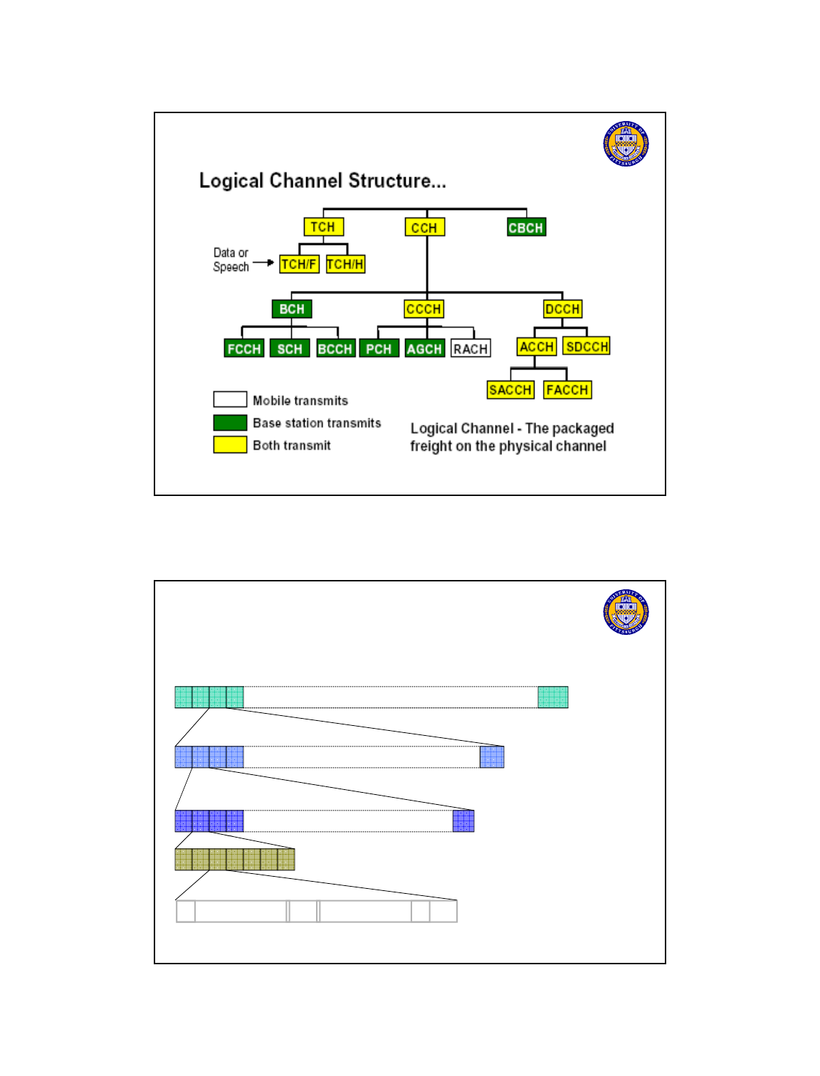
GSM Channels
Physical Channel – 1 time slot on a uplink/downlink radio carrier.
125 radio carriers, 8 slots per carrier => 1000 physical channels
Traffic Channels
Full rate (TCH/F) at 22 8 kb/s or half rate (TCH/H) at 11 4 kb/s
Full
rate
(TCH/F)
at
22
.
8
kb/s
or
half
rate
(TCH/H)
at
11
.
4
kb/s
Physical channel = full rate traffic channel (1 timeslot) or 2 half rate
traffic channels (1 timeslot in alternating frames)
Full rate channel may carry 13 kb/s speech or data at 12, 6, or 3.6 kb/s
Half rate channel may carry 6.5 kb/s speech or data at 6 or 3.6 kb/s
Control Channels
Three groups of logical control channels
1
BCH (b d t h l ) i t
t
lti i t d li k l
Telcom 2700
32
1
.
BCH
(b
roa
d
cas
t
c
h
anne
l
s
)
: po
i
n
t
-
t
o-mu
lti
po
i
n
t
d
own
li
n
k
on
ly
2. CCCH (common control channel): for paging and access
3. DCCH (dedicated control channel): bi-directional point-to-point signaling
GSM Channels
Telcom 2700
33
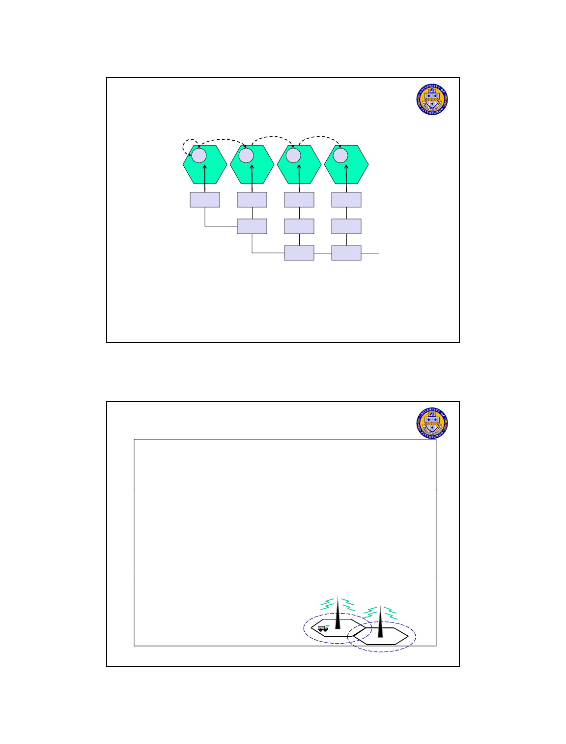
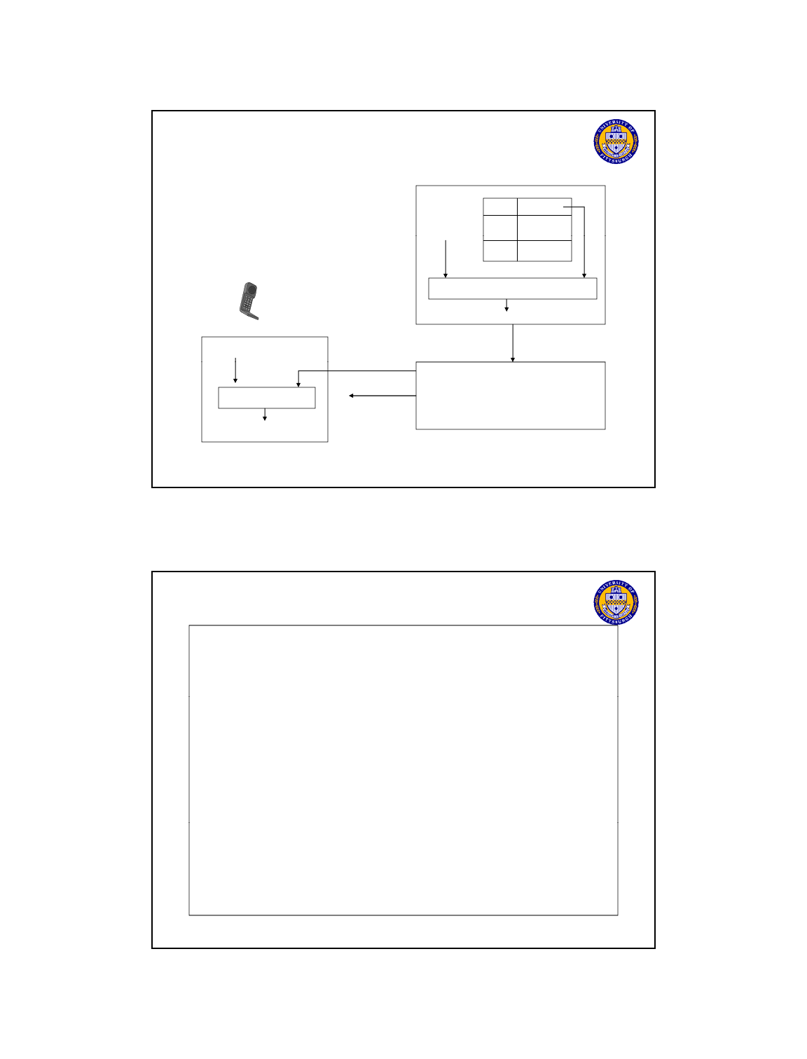
Framing Scheme in GSM (Traffic Channels)
1 2 3 4 2048
Hyperframe: 3 hours 28 min 53.76 s
Framing scheme is implemented for encryption and identifying time slots
1 2 3 4 51
1 2 3 4 26
Superframe: 6.12 s
Traffic Multiframe: 120 ms
Telcom 2700
34
TB
TBData (57 bits) TS GPData (57 bits)
1 2 3 5 6 7 8
Frame: 4.615 ms
Slot: 577 s

GSM Logical Channels (cont)
BCH (broadcast channels): point-to-multipoint downlink only
BCCH (broadcast control channel): send cell identities, organization
info about common control channels, cell service available, etc
FCCH (frequency correction channel): send a frequency correction
FCCH
(frequency
correction
channel):
send
a
frequency
correction
data burst to effect a constant frequency shift of RF carrier
SCH (synchronization channel): send TDMA frame number and base
station identity code to synchronize MSs
CCCH (common control channel): for paging and access
PCH (paging channel): to page MSs
AGCH
(
access
g
rant channel
)
: to assi
g
n MSs to stand-alone
Telcom 2700
35
(g )g
dedicated control channels for initial assignment
RACH (random access channel): for MS to send requests for
dedicated connections
GSM Logical Channels (cont)
DCCH (dedicated control channel): bidirectional point-to-
point -- main signaling channels
SDCCH (stand-alone dedicated control channel): for service
request, subscriber authentication, equipment validation,
assignment to a traffic channel
SACCH (slow associated control channel): for signaling associated
with a traffic channel, eg, signal strength measurements
FACCH (fast associated control channel): for preemptive signaling
on a traffic channel, eg, for handoff messages –sets S (stealing
Flag in traffic slot)
Control channels are organized in a complex frame
Telcom 2700
36
Control
channels
are
organized
in
a
complex
frame
structure
Certain ARFCNs are assigned as having a control channel – TS0 is
used for control channel
One control channel per sector per cell.

1 2 3 4 2048
Hyperframe: 3 hours 28 min 53.76 s
Framing scheme is implemented for encryption and identifying time slots
Framing Scheme in GSM (Control Channels)
1 2 3 4 26
1 2 3 4 51
Superframe: 6.12 s
Control Multiframe: 235.4 ms
Telcom 2700
37
TB
TBData (57 bits) TS GPData (57 bits)
1 2 3 5 6 7 8
Frame: 4.615 ms
Slot: 577 s
Control Channel Multiframe (Forward link TS0)
0
F
1
S
2
B
3
B
4
B
5
B
6
C
7
C
8
C
9
C
10
F
11
S
12
C
13
C
20
F
21
S
22
C
39
C
40
F
41
S
42
C
49
C
50
I
…
……
14
C
Control Multiframe = 51 TDMA Frames
235 ms
Control Channel Multiframe (Reverse link for TS0)
F: FCCH burst (BCH)
S: SCH burst (BCH)
B: BCCH burst (BCH)
C: PCH/AGCH burst (CCCH)
I: Idle
Control Multiframe = 51 TDMA Frames
235 ms
Telcom 2700
38
0
R
1
R
2
R
3
R
4
R
5
R
6
R
46
R
47
R
48
R
49
R
50
R
………………………………..
R: Reverse RACH burst (CH)
Send
message
begin
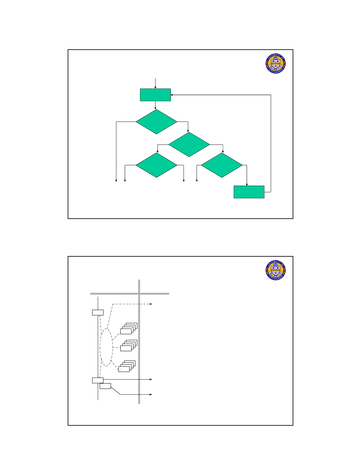
GSM Reverse Access Channel Protocol
Other
Transmissions
In this slot
?
Base detects
messages?
Another
ith
yes
no
y
es
no
yes
no
y
es no
Telcom 2700
39
messages w
ith
same 5-bit
code?
Random
Time delay
y
Access
Fails
Access
Succeeds
Max attempts?
Access
conflict
y
GSM Access protocol for the random access channel RACCH.
System architecture: network and switching
subsystem
Components
MSC (Mobile Services Switching Center):
IWF (Interworking Functions)
network
subsystem
MSC
fixed partner
networks
ISDN
PSTN
ISDN (Integrated Services Digital Network)
PSTN (Public Switched Telephone Network)
PSPDN (Packet Switched Public Data Net.)
CSPDN (Circuit Switched Public Data Net.)
Databases
HLR (Home Location Register)
MSC
SS7
EIR
HLR
VLR
Telcom 2700
41
VLR (Visitor Location Register)
EIR (Equipment Identity Register)
MSC
IWF
ISDN
PSTN
PSPDN
CSPDN
VLR

Network and switching subsystem
NSS is the main component of the public mobile network GSM
switching, mobility management, interconnection to other networks,
system control
Com
p
onents
p
Mobile Services Switching Center (MSC)
controls all connections via a separated network to/from a mobile
terminal within the domain of the MSC - several BSC can belong to a
MSC
Databases (important: scalability, high capacity, low delay)
Home Location Register (HLR)
central master database containing static user data, (mobile number,
Telcom 2700
42
billing address, service subscribed, etc.) and dynamic data of all
subscribers last VLR location
Visitor Location Register (VLR)
local dynamic database for a subset of HLR data, including data about
all user currently in the domain of the MSC attached to VLR
Mobile Services Switching Center
The MSC (mobile switching center) plays a central role in GSM
switching functions
additional functions for mobility support
mana
g
ement of network resources
g
interworking functions via Gateway MSC (GMSC)
integration of several databases
Functions of a MSC
specific functions for paging and call forwarding
termination of SS7 (signaling system no. 7)
mobility specific signaling
location registration and forwarding of location information
Telcom 2700
43
location
registration
and
forwarding
of
location
information
provision of new services (fax, data calls)
support of short message service (SMS)
generation and forwarding of accounting and billing information

Operation subsystem
OSS (Operation Subsystem) enables centralized
operation, management, and maintenance
Components
A th ti ti C t (AUC)
A
u
th
en
ti
ca
ti
on
C
en
t
er
(AUC)
generates user specific authentication parameters on request of a
VLR
authentication parameters used for authentication of mobile
terminals and encryption of user data on the air interface within the
GSM system
Equipment Identity Register (EIR)
registers GSM mobile stations and user rights
Telcom 2700
44
registers
GSM
mobile
stations
and
user
rights
stolen or malfunctioning mobile stations can be locked and
sometimes even localized
Operation and Maintenance Center (OMC)
different control capabilities for the radio subsystem and the network
subsystem
GSM Protocol Stack
Three Layers specified in the protocol
Network layer has three sublayers
1. Call Management
Establishment, maintenance, and termination of circuit-switched
calls
2. Mobility Management
Registration, authentication, and location tracking
3. Radio Resource Management
Establishment, maintenance, and termination of radio channel
connections
Telcom 2700
45
Link Layer
Uses variation of ISDN LAPD protocol – termed LAPD
m
Physical layer (already discussed)
Time slot on a 200 KHz carrier – absolute radio frequency
channel number (ARFCN)
Air Interface
U
m
Abis A
GSM Protocol Stack
CM
MM
RRM
LAPD
m
CM
MM
RRM
MTP
SCCP
LAPD
m
LAPD
RRM
LAPD MTP
SCCP
RRM
Telcom 2700
46
radio 64 kbpsradio 64 kbps 64 kbps 64 kbps
Mobile
station
Base transceiver
station
Base transceiver
controller
Mobile services
switching center
CM: call management
MM: mobility management
RRM: radio resources management
SCCP: signal connection control part (SS7)
MTP: message transfer part (SS7)
LAPD: link access protocol-D channel (ISDN)
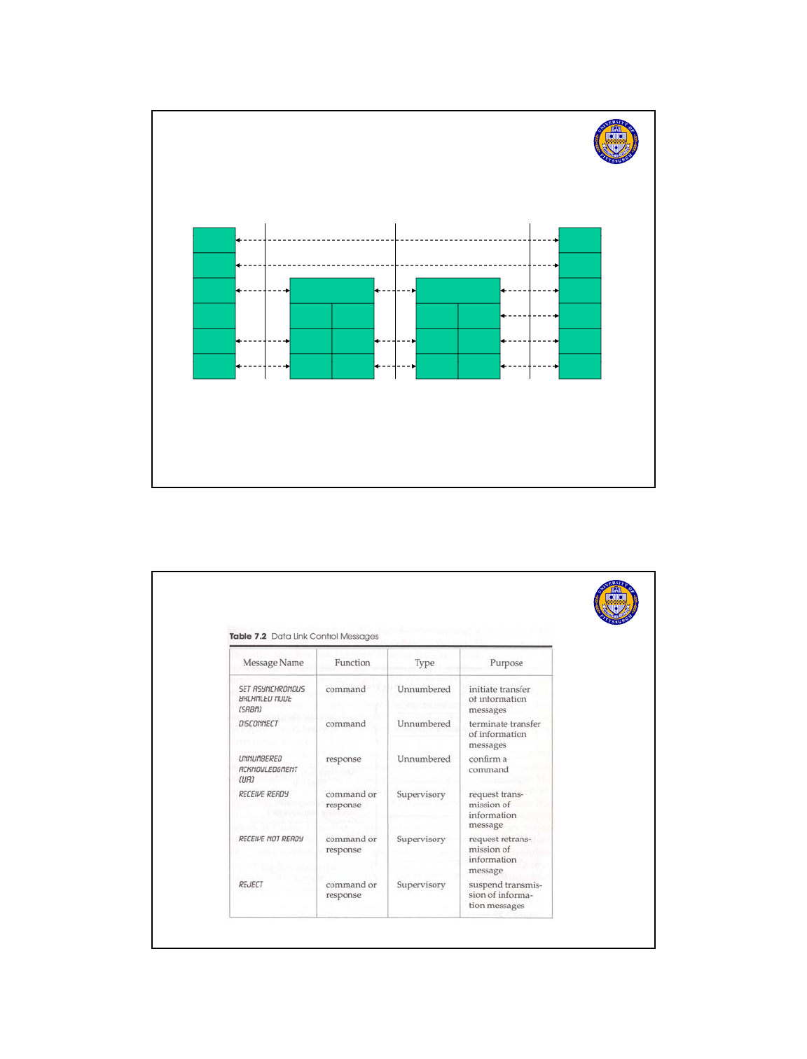
GSM Data Link LAPD
m
Messages
Telcom 2700
47
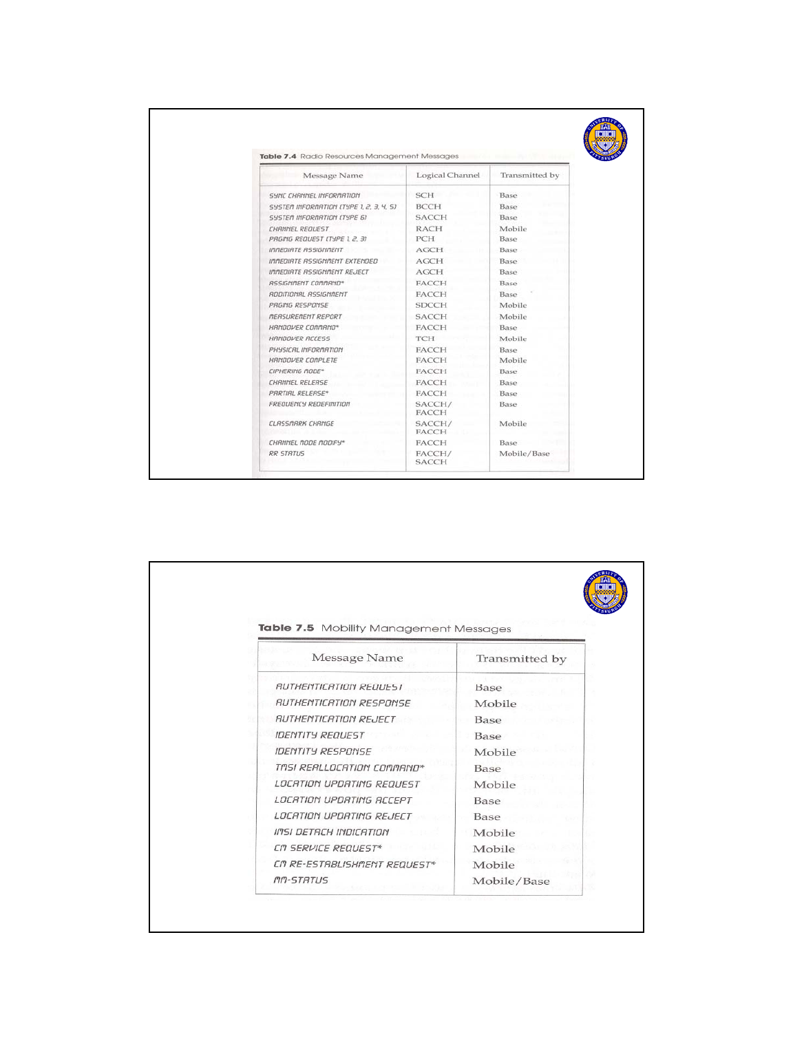
GSM RRM Messages
Telcom 2700
48
GSM MM Messages
Telcom 2700
49
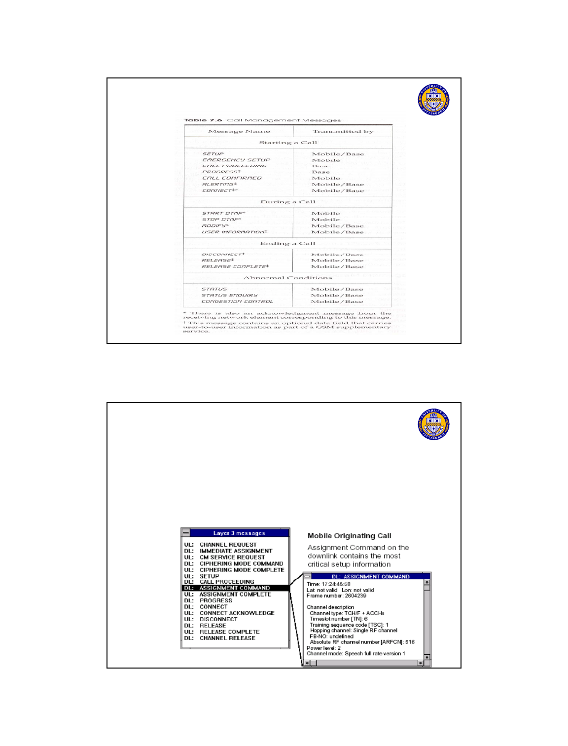
GSM CM Messages
Telcom 2700
50
Sample GSM Message
Assignment Command
message on FACCH used in handoff to inform of new channel info
Bit Position Information
1-4 Protocol Discriminator 0110 (RRM – message)
5-8 Transaction identifier
9-16 Message Type 00101110
17-40 Channel Description
41-48 Power Command
variable Optional Data
Telcom 2700
51

GSM Call Management
Call Operation Types
Registration
Upo
n
po
w
e
rin
g
up,
t
h
e
M
S
sca
n
s
co
mm
o
n
co
n
t
r
o
l
Upon
powering
up,
the
MS
scans
common
control
channels and locks onto channel with strongest signal
Searches for FCCH on RF carrier, finds SCH to synch up
After synchronization the MS decodes BCCH – decides
whether to update location register or not.
Once registered or locked on to BCCH
Mobile Originating (MO) Call
Telcom 2700
52
Mobile types in number presses Send
Mobile Terminating (MT) Call
Mobile registered and phone On – received incoming
call
GSM Registration
RF + FCCH
Lock on strong freq.
and find FCCH
SCH sync + training
Find SCH channel for
sync. and training
BCCH system parameters
Gets cell and
system parameters
Telcom 2700
53
RACH channel request
Request stand alone
dedicated channel
AGCH channel assignment
SDCCH established
GSM Registration (cont)
SDCCH location update
Make location update
request
SDCCH challenge
Computes challenge
response to verify
identity
SDCCH challenge response
SDCCH ciphered mode
Initiate encryption of
Telcom 2700
54
Initiate
encryption
of
data for transmission
Ack ciphered mode
Location update confirm
Complete location
update process
Ack
Location Registration
Register at power up/call placement/(power down)/ when detect a new
location area id
Walkthrough Roaming case
1. Mobile-> MSC signals HLR update VLR pointer
2. Auc verifies user- may issue challenge/response
3. HLR – gives VLR mobile service profile
4. HLR – deregisters mobile from last VLR location
Target ITU-T bound on location registration 4sec
Location Update Types
Intra – VLR ( LAs attached to same VLR)
Telcom 2700
55
Only change LA id in VLR ( local signaling)
Target ITU-T location update time 2 sec
Inter –VLR ( LAs attached to different VLR)
must signal HLR to update VLR pointer
Target ITU-T Location update time 4 sec
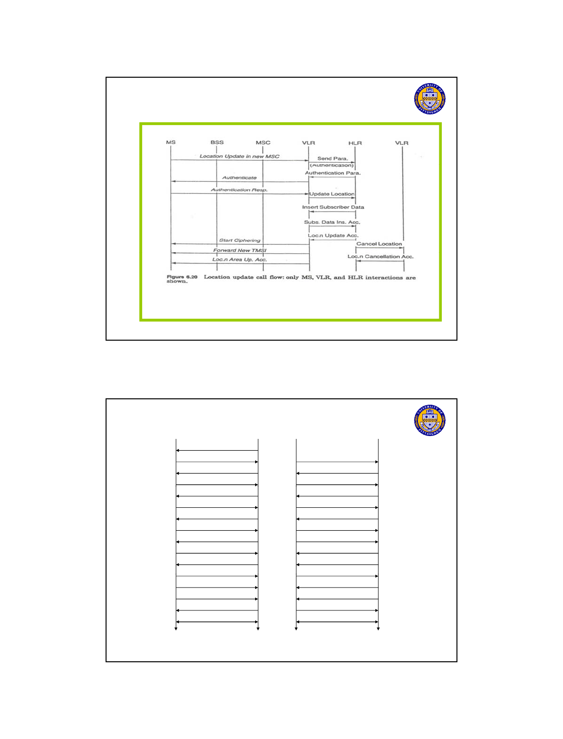
Location Update Call Flow
Telcom 2700
57
MTC/MOC general behavior
BTSMS
paging request
channel request
immediate assignment
paging response
BTS
MS
channel request
immediate assignment
service request
MTC MOC
authentication request
authentication response
ciphering command
ciphering complete
setup
call confirmed
assignment command
assi
g
nment com
p
lete
authentication request
authentication response
ciphering command
ciphering complete
setup
call confirmed
assignment command
assi
g
nment com
p
lete
Telcom 2700
58
gp
alerting
connect
connect acknowledge
data/speech exchange
gp
alerting
connect
connect acknowledge
data/speech exchange
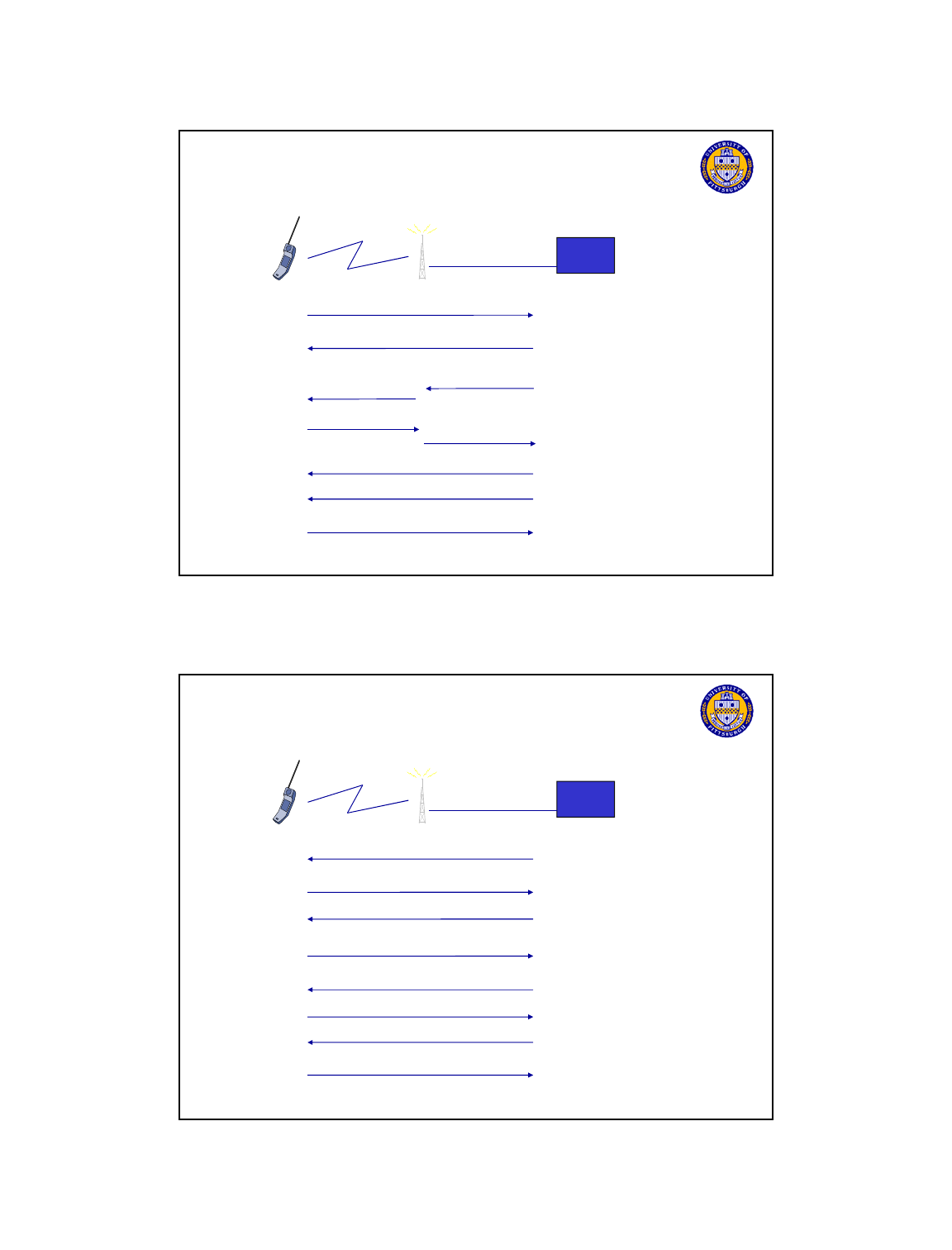
GSM MOC Calling from MS
MSC
Setup Request
Fetches subscriber info
from VLR to process
call, acks caller
Dial called
party
Call Proceeding
Allocates trunk +
radio channel
Radio channel
Ack
Tune to
radio freq.
Clt
Cll td
Telcom 2700
60
C
omp
l
e
t
e
C
a
ll
connec
t
e
d
through PSTN
Alerting
Connect
Connect ack
Alerts caller
Called party picks up
Call can proceed
GSM MTC Calling to MS
MSC
PCH page request
Incoming call from PSTN
Request
dedicated
control
channel
RACH channel request
Allocates control
channel
Answer page
SDCCH h ll
AGCH assignment
SDCCH paging response
Telcom 2700
62
Request authentication
SDCCH
c
h
a
ll
enge
Request ciphering on
channel
Computes
response
SDCCH challenge response
SDCCH ciphering mode
Ciphering mode complete
Begin
ciphering
GSM MTC Calling to MS (cont)
MSC
Notify call
Accept call
SDCCH i t
SDCCH setup
SDCCH setup ack
Telcom 2700
63
Assign traffic channel
SDCCH
ass
i
gnmen
t
Alert called party
Tune to
freq.
Assignment complete
FACCH alerting/connect
FACCH connect ack
Start
connection
GSM Features
Discontinuous Transmission (DTX)
Handset/BSC contain voice activity detectors (much of a conversation is
silence!)
If no speech detected NO information is transmitted – TDMA slot left empty
Saves battery power in mobile
Saves
battery
power
in
mobile
Reduces co-channel and adjacent channel interference
Comfort Noise is periodically played back if long silence period
Power control
Both mobile and BTS regulate power (increase and decrease)
Mobile power adjusted in 2 dB levels, BTS power adjusted in 4 dB levels
Conserves battery power in mobile
Reduces interference
Telcom 2700
64
Mobile Assisted Handoff (MAHO)
Mobile takes measurements of signals strength of radio channels in adjacent
cells - reports to BSC and MSC to pick cell for handoff
Sleep Mode
Handset once registered with network will be assigned a sleep mode level
Checks paging channel for page/SMS periodically depending on level
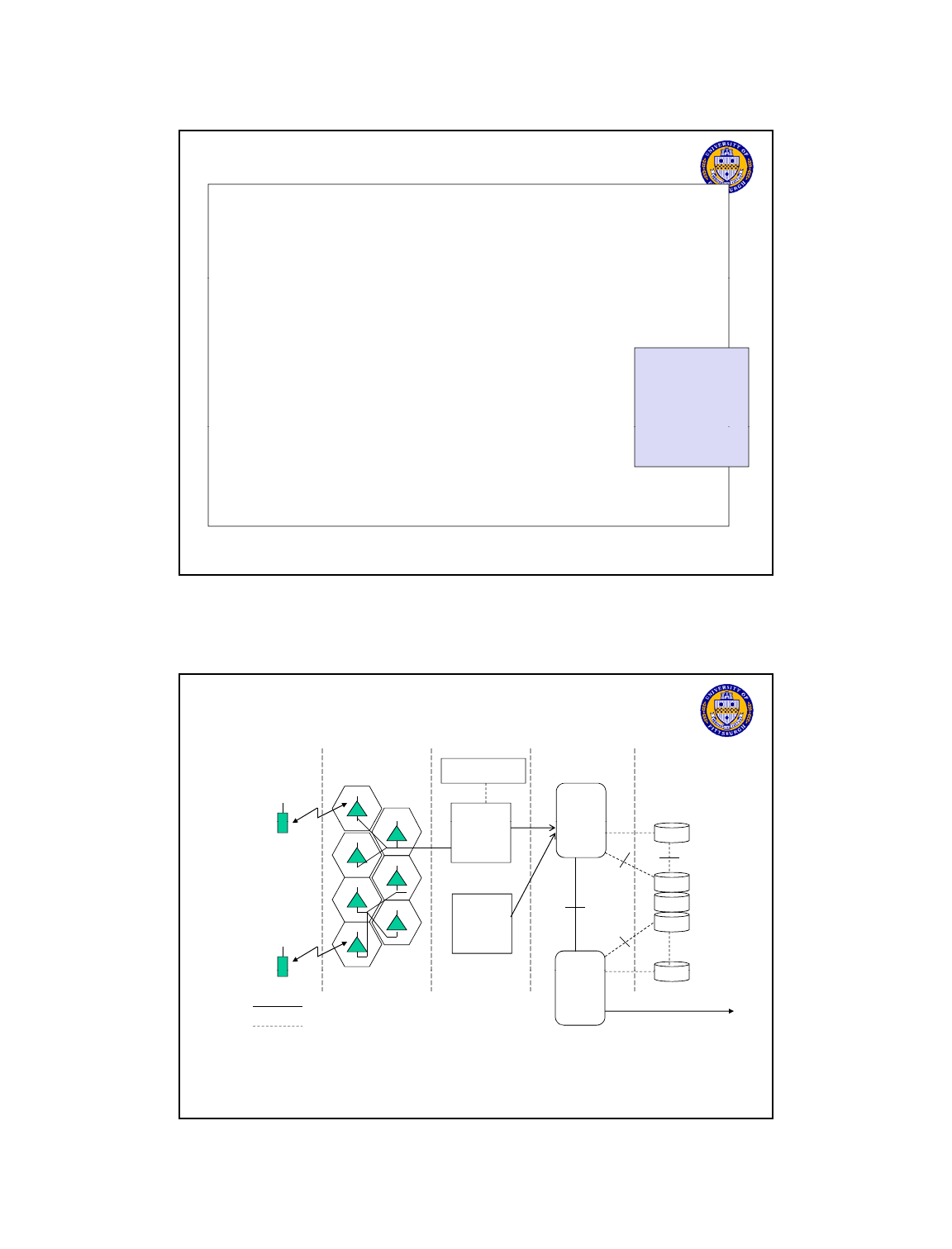
GSM Mobility Management
Mobility Types
Track location of users for incoming calls/SMS
L
ocat
i
o
n r
eg
i
st
r
at
i
o
n
/aut
h
e
n
t
i
cat
i
o
n
/pag
in
g
Location
registration/authentication/paging
Divide coverage area into non-overlapping groups of
cells – assign each a unique id
Location Area ID periodically broadcast by each cell
As a mobile moves/turns phone on – it listens to location
area id – if different from last one registered in – performs a
location update/authentication procedure with VLR and
possibly HLR
Telcom 2700
65
Call in progress mobility
Handoff call from one BTS to another BTS
MAHO by mobile reporting measurements of signal
strength
Location Management
Location Area ( LA)
Divide coverage into non-overlapping groups of cells
Assign each LA a unique id
Assign
each
LA
a
unique
id
Location Area ID is periodically broadcast by each cell
Two level database hierarchy HLR/VLR
HLR points to VLR where mobile located
VLR entry points to LA where mobile last located
In large networks may have HLR split among regions
with aggregate info cross region
Location
Area 1
Location
Location
Area 3
Telcom 2700
66
with
aggregate
info
cross
region
Location
Area 2
Location Area and Cell Identification Parameters
MCC – Mobile Country Code
Uniquely identify the country of the GSM subscriber
MNC – Mobile Network Code
Identifies the GSM operator within the country. Each
country can have several GSM operators each having a
unique MNC.
LAI – Location Area Identity
Uniquely identifies a location area in the network
Made up of MCC + MNC + LAC
CGI – Cell Global Identifier
Uniquely identifies the cell within the network
Made up of LAI + CI
LAC – Location Area Code
Defines a location area, which consists of a group of cells.
Each MNC can have several LACs.
CI – Cell Identity
Uniquely identifies a cell in a location area.
Mobile network code
unique to each
operator
in a country
Telcom 2700
67
Location Areas
Define group of cells
Cell Identity
Unique to each cell
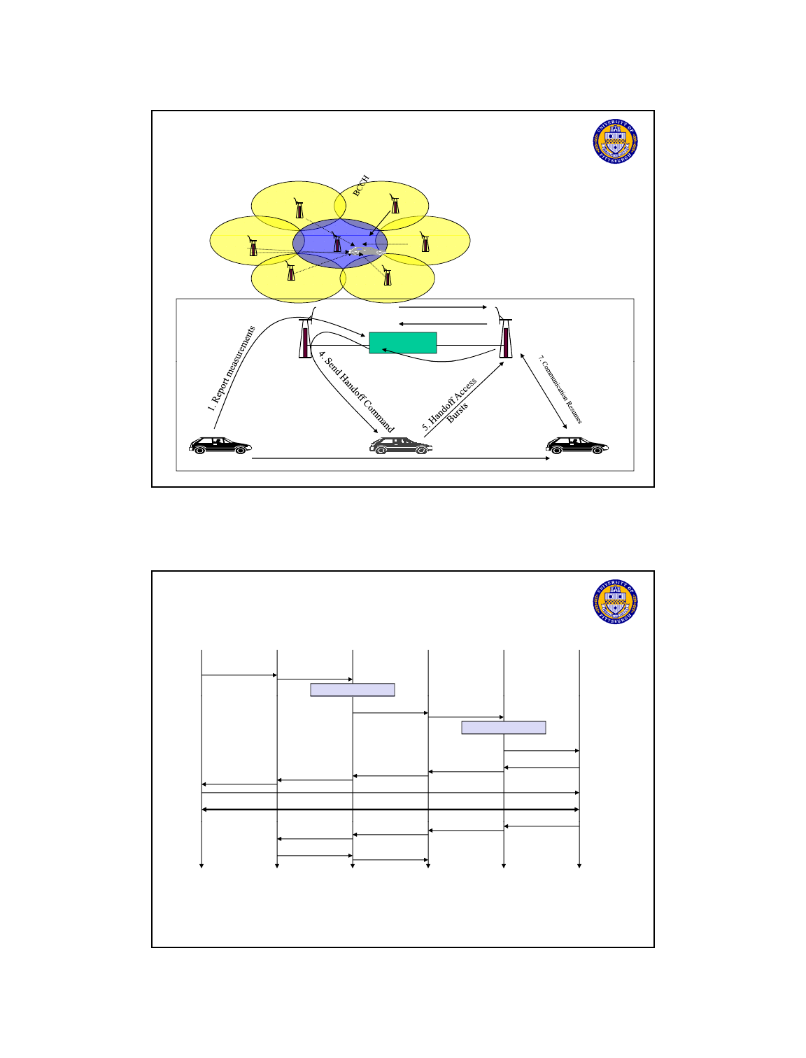
GSM Handoffs
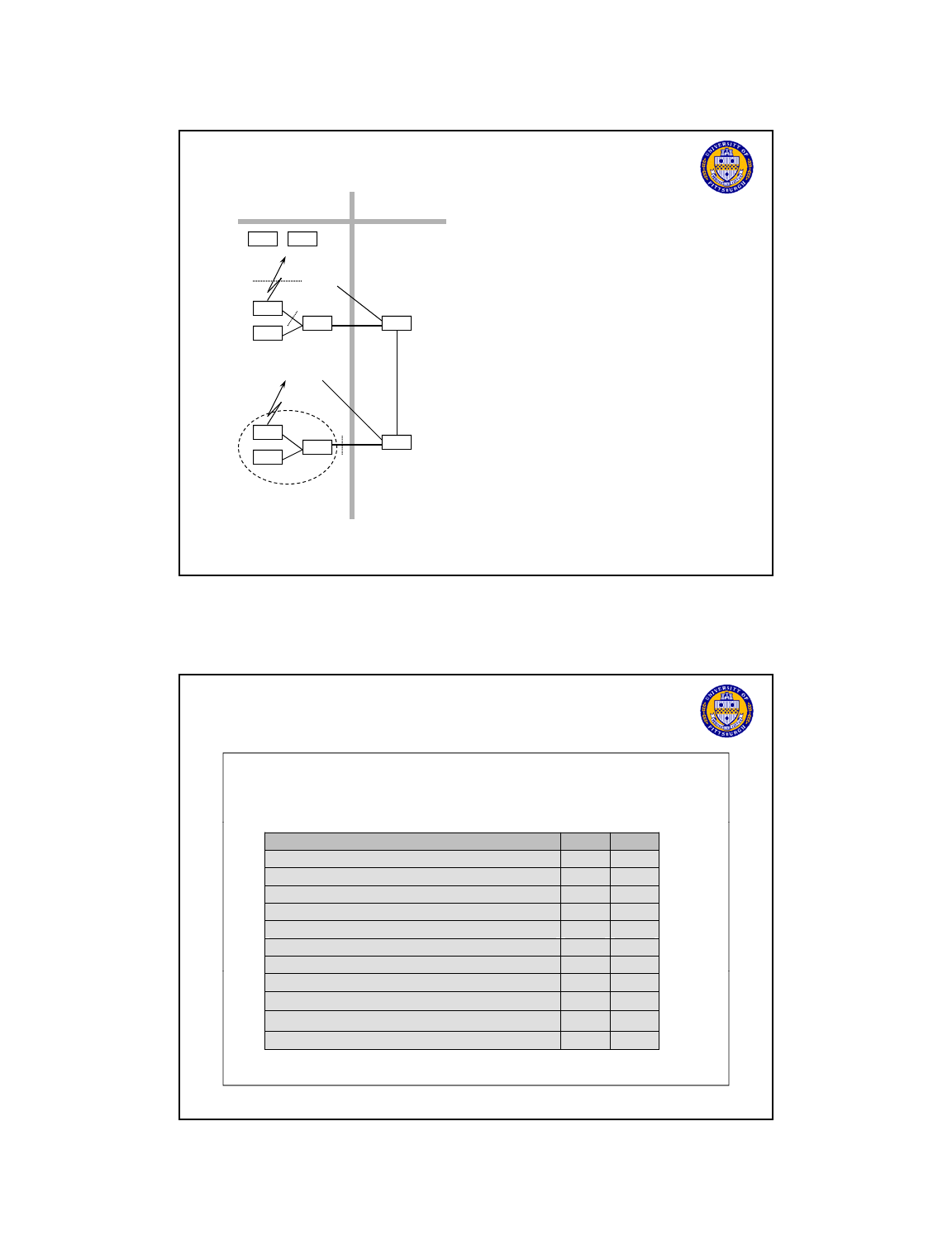
Handoff major decision-making stages
Identify the need
Identify the candidate
Evaluate the candidates
Evaluate
the
candidates
Select a target cell
Types of handoffs
Intra-Cell : Handoff between sectors of same cell
Intra-BSS: if old and new BTSs are attached to same base
station
MSC is not involved
Telcom 2700
68
Intra-MSC: if old and new BTSs are attached to different
base stations but within same MSC
Inter-MSC: if MSCs are changed
Handoff Forward, Handoff Back, Handoff to a Third
Types of Handoff
MS MS MS MS
Intracell
Standard
Inter-BSC
Intersystem handoff
MSC
MSC
BSC BSCBSC
BTS BTS BTSBTS
Telcom 2700
69
MSC
MSC
Handoff initiation:
Base station or MS notices signal is weakening (when the received
signal strength goes below a certain threshold value)
Base station or MS sends a handoff measurement re
q
uest
GSM - Handoff
q
message to its BSC/MSC
BSC/MSC requests
neighbor base stations to report their reception of mobile’s signal
strength
MS to measure strength of neighbor base stations on downlink
(called Mobile Assisted Handoff)
BSC/MSC picks neighbor base station with highest received signal
strength combination in p and do nlink to handoff too
Telcom 2700
70
strength
combination
in
u
p
and
do
w
nlink
to
handoff
too
Mobile listens to the
BCCH of six neighboring
base stations
GSM - Mobile Assisted Handoff
BTS1
BTS2
MSC
2. Request channel
3. Activate Channel
BTS1
BTS2
Break before Make
handoff (hard handoff)
Telcom 2700
72
6. Handoff Detection
Handoff Procedure
BTS
old
BSC
new
measurement
result
BSC
old
MSC
MS
measurement
report
HO decision
BTS
new
HO access
Link establishment
HO required
HO request
resource allocation
ch. activation
ch. activation ack
HO request ack
HO command
HO command
HO command
HO com
p
lete
HO complete
Telcom 2700
73
p
HO
complete
clear command
clear command
clear complete
clear complete
Security in GSM
Security services
access control/authentication
user SIM (Subscriber Identity Module): secret PIN (personal
identification number)
SIM
network: challenge response method
SIM
network:
challenge
response
method
confidentiality
voice and signaling encrypted on the wireless link (after successful
authentication)
anonymity
temporary identity TMSI
(Temporary Mobile Subscriber Identity)
newly assigned at each new location update (LUP)
encrypted transmission
“secret”:
• A3 and A8
available via the
Internet
• network
p
roviders
Telcom 2700
74
encrypted
transmission
3 algorithms specified in GSM
A3 for authentication (“secret”, open interface)
A5 for encryption (standardized)
A8 for key generation (“secret”, open interface)
p
can use stronger
mechanisms
GSM System Architecture
B, C, D, E, F
MAP Interfaces
Mobile
Switchin
g
OMC - Radio
Base
Si
BTS
BTS
UM
Interface
A-Bis
Interface
A Interface B Interface
VLR
HLR
AUC
EIR
VLR
Mobile
g
Center
(MSC)
S
tat
i
on
Controller
(BSC)
Base
Station
Controller
(BSC)
BTS
BTS
BTS
BTS
BTS
D Interface
F
Interface
C
Interface
E
Interface
Telcom 2700
75
VLR
Switching
Center
(MSC)
Traffic and Signaling
Signaling only
VLR = Visitor Location Register
HLR = Home Location Register
EIR = Equipment Identity Register
AUC = Authentication Center
BTS = Base Transceiver Station
ADC = Admission Data Center
OMC = Operation Maintenance Center
PSTN
Authentication and Encoding
Mobile Station Base Station Controller
A Interface
Service
Switching
Point
Radio
Control
Pit
VLR
S
p
eech and data in clear
Signaling in clearEncoded
Speech,
Data, and
Signaling
RAND
SRES
Kc
A5
Base
transceiver
SRES
RAND
Ki
A3
A8
Kc
A5
Encoded
Speech
Data and
Signaling
Speech and Data
S
i
g
n
a
lin
g
in
C
l
ea
r
Telcom 2700
76
P
o
i
n
t
station
Sg a g Cea
Authentication Procedure in GSM
AUC
Random
Number
RAND
IMSI (1)
Ki(1)
::
SRES Signed Response 32 bit
A3 Authentication Algorithm
Ki 128-bit subscriber key unique to each subscriber
RAND 128
bit random n mber
RAND
Ki
RAND, SRES
A3
SRES
IMSI (X)
Ki(X)
RAND
128
-
bit
random
n
u
mber
Telcom 2700
77
MS
MSC
SRES
RAND
SRES
A3
COMPARES SRES VALUES RECEIVED
FROM AUC AND MOBILE STATION
IF IDENTICAL THEN MS IS AUTHENTICATED
Ciphering Procedure in GSM
AUC
Random
Number
RAND
IMSI (1)
Ki(1)
::
Kc 64 bit Ciphering Key
A8 Ciphering Algorithm
Ki 128-bit subscriber key unique to each subscriber
RAND 128
bit random n mber
RAND
Ki
RAND, Kc
A8
Kc
IMSI (X)
Ki(X)
RAND
128
-
bit
random
n
u
mber
Telcom 2700
78
MS
MSC
Kc to BTS
RAND
Kc
A8
SEND RAND TO MOBILE STATION AND Kc
TO
BSC FOR CIPHERING
Data services in GSM
Circuit Switched Data transmission standardized at 9.6 kbit/s
advanced coding allows 14.4 kbit/s in a standard TDMA slot
Widely deployed and used by WAP GSM phones
not enough bandwidth for multimedia applications
HSCSD (High-Speed Circuit Switched Data)
already standardized
bundling of several time-slots on a radio carrier to get higher data
rate : called AIUR (Air Interface User Rate)
maximum rate 57.6 kbit/s using 4 slots, 14.4 kbps each
(4 slot limit to allow MS to transmit then listen to downlink channel)
Advantages: ready to use, constant quality, simple no additional
equipment needed in network just software upgrades
Telcom 2700
79
equipment
needed
in
network
just
software
upgrades
Disadvantage: channels blocked for voice transmission, expensive,
not supported by all service providers
Most operators now have 2.5G solutions like GRPS or EDGE
in place or 3G UMTS for data sevice

Summary
• Generations of Cellular Systems
• GSM – most widely deployed and used
system
• System Architecture
• Physical Layer
• Protocol Stack
•
Mobility Management
Telcom 2700
80
Mobility
Management
• Security
• Data Service
• GSM being replaced with 3G UMTS
