Ovewiew
Of
The
GSM
System
and
Protocol Architecture
We can use
GSM
as a basic framework to define and develop
the standards for handling the mobility-specific functions
of
next-generation
PCNs.
Moe Rahnema
lobal system for mobile telecom-
munication (GSM) comprises the
CEFT-defined standardization of
the services, functional/subsystem
interfaces, and protocol archi-
tecture, based on the use of
worldwide standards produced by CCI7T and CCIR,
for a pan-European digital land mobile system
primarily intended to serve users in motor vehi-
cles. The digital mobile radio networks, for which
GSM represents the European standards, pro-
vide powerful message signaling capabilities that
facilitate and enhance roaming,compared to the first
generation analogue systems, through automatic
network location detection and registration.
GSM provides terminal mobility, with person-
al mobility provided through tbe insertion of a
subscriber identity module (SIM) into the GSM net-
work (mobile station). The SIM carries the personal
number assigned to the mobile user. The GSM-based
cellular mobile networks are currently in widespread
use in Europe. At the present time, the next gen-
eration of personal communication services
(PCS) beyond GSM is also being considered.
These third generation systems, known as univer-
sal personal communication networks (PCN) will be
using lower power handsets to provide personal
mobility to pedestrians, aswell. The PCS low-power
handsets are expected to eliminate the need to
have different handsets for wide-area (cellular)
and local (cordless) applications. The universal PCS
will also provide a higher quality of personal-service
mobility across the boundaries of many different net-
works (mobile and fixed, wide- and local-area).
Many network capabilities, however, such as
mobility management, user security protection, and
resource allocation, addressed in GSM, are also some
of the critical requirements and issues in UPC net-
works of the future. GSM is expected to play a
major role in the specification of the standards
for UPC. In the United Kingdom, PCN is already
being designed and deployed with close adher-
ence to the GSM standards other than the differ-
ent operating frequencies (GSM operates at
900
MHz and the United Kingdom PCN operates at
1800
MOE
RAHNEMA
is a
principal communication
engineer at Motorola Satellite
Communications.
L
MHz). Generally, GSM may be viewed as a frame-
work for studying the functions and issues that
are specific to cellular type personal communication
networks, whatever the means of implementation
might be.
In applying and extending GSM to the next gen-
eration personal communication networks, how-
ever, one should be careful in differentiating some
of the implementation specifics unique to the GSM
network architecture and application from the func-
tions and issues that would be more or less gener-
ally applicable and relevant to cellular networking.
It is with this point in mind that the reader should
view GSM as a framework or platform on which
to build his or her vision of how GSM may be used
as a guide to design and build the next generation
networks. In that regard, a good understanding of
the GSM standards and network functions is
essential for the professional working on the next
generation personal communication networks. This
article is intended to assist with this objective.
The
Cellular
Concept
ellular mobile communication is based on the
C
concept of frequency reuse. That is, the limit-
ed spectrum allocated to the service is partitioned
into, for example, N non-overlapping channel
sets, which are then assigned in a regular repeat-
ed pattern to a hexagonal cell grid. The hexagon
is just a convenient idealization that approximates
the shape of a circle (the constant signal level
contour from an omnidirectional antenna placed
at the center) but forms a grid with no gaps or
overlaps. The choice ofN is dependent on many trade-
offs involving the local propagation environment,
traffic distribution, and costs. The propagation envi-
ronment determines the interference received from
neighboring co-channel cells which in turn gov-
erns the reuse distance, that is, the distance
allowed between co-channel cells (cells using the
same set of frequency channels).
The cell size determination is usually based on
the local traffic distribution and demand. The more
the concentration of traffic demand in the area,
92
0163-6804/93/$03.00 19930
IEEE
IEEE
Communications Magazine
April
1993
-
__
.
Authorized licensed use limited to: UNIVERSITI SAINS MALAYSIA. Downloaded on August 5, 2009 at 23:41 from IEEE Xplore. Restrictions apply.

the smaller the cell has to be sized in order to avail
the frequency set to a smaller number of roaming
subscribers and thus limit the call blocking proba-
bility within the cell. On the other hand, the
smaller the cell is sized, the more equipment will
be needed in the system as each cell requires the nec-
essary transceiver and switching equipment,
known as the base station subsystem
(BSS),
through which the mobile users access the net-
work over radio links. The degree to which the
allocated frequency spectrum is reused over the cel-
lular service area, however, determines the spectrum
efficiency in cellular systems. That means the
smaller the cell size, and the smaller the number
of cells in the reuse geometry, the higher will be
the spectrum usage efficiency. Since digital mod-
ulation systems can operate with a smaller signal
to noise (i.e., signal to interference) ratio for the
same service quality, they, in one respect, would allow
smaller reuse distance and thus provide higher spec-
trum efficiency. This is one advantage the digital cel-
lular provides over the older analogue cellular radio
communication systems. The interested reader may
refer to
[1,2]
for the details on spectrum efficien-
cy analysis in cellular network.
It isworthmentioning that thedigitalsystems have
commonly used sectored cells with 120-degree or
smaller directional antennas to further lower the
effective reuse distance. This allows a smaller
number of cel!s in the reuse pattern and makes a
larger fraction of the total frequency spectrum avail-
able within each cell. Currently, research is being
done on implementing other enhancements such
as the use
of
dynamic channel assignment strate-
gies for raising the spectrum efficiency in certain
cases, such as high uneven traffic distribution
over cells.
The Network Infrastructure
he cellular concept
of
networking is based on the
T
superposition of a distributed star type net-
work architecture on the existing fixed landline tele-
phony communication infrastructure. The basic
network architecture is illustratedin Fig.
1.
The tele-
phony network is used to provide not only the
communication links between a mobile user and
a fixed landline user, but also to provide the con-
nectivity between the mobile users roaming in remote-
ly located cells or in the domain of mobile networks
operated by different service providers. The
BSSs,
provide management of the radio resources,
and the switching between the radio channels and
the TDM slots on their connections with the
mobile switching center (MSC). MSCs link groups
of neighboring
BSSs
through point-to-point land-
line or microwave-based El trunks. The MSC
acts as the nerve center of the system. It controls
call signaling and processing, and coordinates the
handover
of
the mobile connection from one
base station to another as the mobile roams
around. Each MSC is in turn connected to the
local public switched telephony network (PSTN,
or ISDN) to provide the connectivity between the
mobile and the fixed telephony users, as well as the
necessary global connectivity among the MSCs of
the cellular mobile network. This is intended to make
it possible for any mobile user to communicate
with any other mobile
or
fixed telephony user in
the world. Thus, the global connectivity provided
Figure
1.
Cellular network infrastructure.
by the existing landline telephony infrastructure
is used to link up the cellular mobile subscribers
throughout the world.
Direct links between certain “local” MSCs
may also be provided
to
allow the communication
between two mobile users to bypass the telepho-
ny network when there is considerable traffic
flow between the mobile users roaming in the
areas under the coverage of those MSCs. Thus,
the communication path between any two mobile
users roaming under the coverage of two “local”
MSCsmayormaynot switch throughthepublictele-
phony network. It depends on the connectivity
provided between the two MSCs. The MSC may also
connect to public data networks (PDN), such as
the packet-switched networks, to provide the mobiles
with access to data services.
SM
defines anumber of networkdatabases that
G
are used in performing the functions of mobil-
ity management and call control in a public land
mobile network (PLMN). These elements include
the location registers consisting of the home loca-
tion register (HLR), and the visiting location reg-
ister
(JXR),
the equipment identity register (EIR),
and the authentication center (AC). The HLR main-
tains and updates the mobile subscriber’s loca-
tion and his or her service profile information.
The VLR maintains the same information local-
ly, where the subscriber is roaming. The VLR is
defined as a stand-alone function (see followingpara-
graph), but is usually viewed by vendors as part of
the MSC. These registers are called service con-
trol points (SCP) in the terminology used in intel-
ligent networking (IN). The EIR is used to list
the subscribers’ equipment identities, which are used
for identification of unauthorized subscriber equip-
ment, and hence denial of service by the network.
The AC provides the keys and algorithm for
maintaining the security
of
subscriber identities, and
for encrypting information passed over the air inter-
face. The MSC is equipped with a service switch-
ing point (SSP) module which is used to query
the databases such as a location register to identi-
fy
where a mobile subscriber is located and what
his or her service profile is, for the routing, and
processing of calls to (or by) the subscriber.
The GSM specifications have defined logically
separate functions and standard interfaces for each
of
the databases, to allow each function to be imple-
mented on a physically separate network compo-
nent. The interfaces are specified via the mobile
application part (MAP) that uses the transaction
i
J
Network Databases and
Standardization
IEEE
Communications Magazine
April
1993
93
--.
Authorized licensed use limited to: UNIVERSITI SAINS MALAYSIA. Downloaded on August 5, 2009 at 23:41 from IEEE Xplore. Restrictions apply.
-
In
GSM,
the radio
channels are
based
on
a
TDM
structure
that is
implemented
on
multiple
subbands
frequency
(TDkW
FDMA).
capability applicationspart (TCAP) of (SS7). These
are all elements of an IN. GSM is considered an
IN application and GSM providers are consider-
ing the GSM implementation as experience in
intelligent networking.
Numbering Plan
he numberingconsistsof at least one international
T
ISDN number allocated to either the mobile sub-
scriber, if the mobile is card operated,
or
to the mobile
station, otherwise. The mobile station ISDN (MSIS-
DN) conforms to the CCIlT E.164 recommenda-
tion, and should, in each country, comply to that
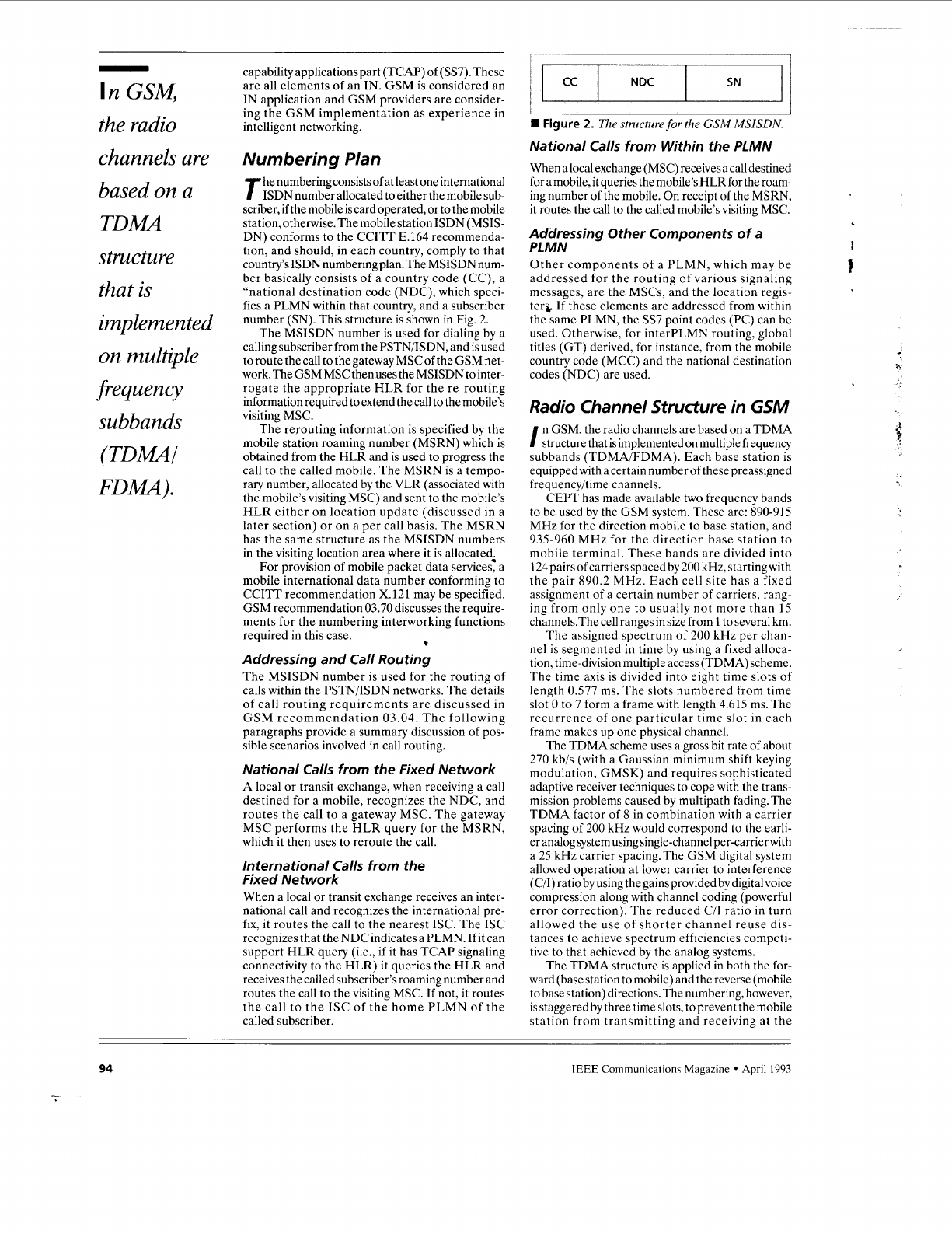
country’s ISDN numbering plan. The MSISDN num-
ber basically consists of a country code (CC), a
“national destination code (NDC), which speci-
fies a PLMN within that country, and a subscriber
number (SN). This structure
is
shown in Fig. 2.
The MSISDN number is used for dialing by a
calling subscriber from the PSTN/ISDN, and is used
toroute thecall to thegateway MSCofthe GSMnet-
work. The GSM MSC then uses the MSISDN to inter-
rogate the appropriate HLR for the re-routing
information required to extend the call
to
the mobile’s
visiting MSC.
The rerouting information is specified by the
mobile station roaming number (MSRN) which is
obtained from the HLR and is used to progress the
call
to
the called mobile. The MSRN
is
a tempo-
rary number, allocated by the VLR (associated with
the mobile’s visiting MSC) and sent
to
the mobile’s
HLR either on location update (discussed in a
later section) or on a per call basis. The MSRN
has the same structure as the MSISDN numbers
in the visiting location area where it is allocated.
For
provision of mobile packet data service; a
mobile international data number conforming to
CCITT recommendation
X.
121 may be specified.
GSM recommendation 03.70 discusses the require-
ments for the numbering intenvorking functions
required in this case.
b
Addressing and Call Routing
The MSISDN number is used for the routing of
calls within the PSTNIISDN networks. The details
of call routing requirements are discussed in
GSM recommendation 03.04. The following
paragraphs provide a summary discussion of pos-
sible scenarios involved in call routing.
National Calls from the Fixed Network
A local
or
transit exchange, when receiving a call
destined for a mobile, recognizes the NDC, and
routes the call to a gateway MSC. The gateway
MSC performs the HLR query for the MSRN,
which it then uses to reroute the call.
International Calls from the
Fixed Network
When a local or transit exchange receives an inter-
national call and recognizes the international pre-
fix, it routes the call to the nearest ISC. The ISC
recognizes that the NDC indicates a PLMN. If it can
support HLR query (i.e.,
if
it has TCAP signaling
connectivity to the HLR) it queries the HLR and
receives the called subscriber’s roaming number and
routes the call to the visiting MSC. If not, it routes
the call to the ISC of the home PLMN of the
called subscriber.
NDC SN
I I
I/
I
I
SN NDC
W
Figure
2.
The
structure
for
the
GSM
MSISDN.
National Calls from Within the PLMN
Whenalocalexchange(MSC)receivesacalldestined
for a mobile, it queries the mobile’s HLR for the roam-
ing number of the mobile. On receipt of the MSRN,
it routes the call
to
the called mobile’s visiting MSC.
Addressing Other Components of a
PLMN
Other components of a PLMN, which may be
addressed for the routing of various signaling
messages, are the MSCs, and the location regis-
ter& If these elements are addressed from within
the same PLMN, the SS7 point codes (PC) can be
used. Otherwise, for interPLMN routing, global
titles (GT) derived, for instance, from the mobile
country code (MCC) and the national destination
codes (NDC) are used.
Radio Channel Structure in
GSM
n
GSM, the radio channels are based on a TDMA
I
structure that is implemented on multiple frequency
subbands (TDMAIFDMA). Each base station is
equippedwith a certain number of these preassigned
frequencyhime channels.
CEPT has made available
two
frequency bands
to be used by the GSM system. These are: 890-915
MHz for the direction mobile to base station, and
935-960 MHz for the direction base station to
mobile terminal. These bands are divided into
124 pairs of carriers spaced by 200 kHz, startingwith
the pair 890.2 MHz. Each cell site has a fixed
assignment of a certain number
of
carriers, rang-
ing from only one to usually not more than
15
channels.The cell ranges in size from
1
to several km.
The assigned spectrum of 200 kHz per chan-
nel is segmented in time by using a fixed alloca-
tion, time-division multiple access (TDMA) scheme.
The time axis is divided into eight time slots of
length 0.577 ms. The slots numbered from time
slot 0 to 7 form a frame with length 4.615 ms.The
recurrence of one particular time slot in each
frame makes up one physical channel.
The TDMA scheme uses a gross bit rate of about
270 kb/s (with a Gaussian minimum shift keying
modulation, GMSK) and requires sophisticated
adaptive receiver techniques to cope with the trans-
mission problems caused by multipath fading.The
TDMA factor
of
8
in combination with a carrier
spacing of 200 kHz would correspond to the earli-
er analog system using single-channel per-carrier with
a 25 kHz carrier spacing. The GSM digital system
allowed operation at lower carrier
to
interference
(CII) ratio by using the gains provided by digital voice
compression along with channel coding (powerful
error correction). The reduced CII ratio in turn
allowed the use of shorter channel reuse dis-
tances to achieve spectrum efficiencies competi-
tive to that achieved by the analog systems.
The TDMA structure is applied in both the for-
ward (base station
to
mobile) and the reverse (mobile
to base station) directions. The numbering, however,
is staggered
by
three time slots, toprevent the mobile
station from transmitting and receiving at the
94
IEEE
Communications Magazine
April
1993
-
Authorized licensed use limited to: UNIVERSITI SAINS MALAYSIA. Downloaded on August 5, 2009 at 23:41 from IEEE Xplore. Restrictions apply.
same time. These time slots are used to carry
user, and signaling
or
control information in
bursts. The bursts are slightly shorter than the
slots, namely .546 ms, to allow for burst timing align-
ment errors, delay dispersion on the propagation
path, and for smoothswitchon/off ofthe transmitter.
GSM defines a variety of traffic and signal-
ing/control channels
of
different bit rates. These
channels are assigned to logical channels derived
from multiframe structuring of the basic eight
slotted TDMA frames just discussed. For this
purpose, two multiframe structures have been
defined: one consisting of 26 time frames (result-
ing in a recurrence interval of 120 ms), and onecom-
prising 51 time frames
(or
236 ms).
The 26 multiframe is used to define traffic
channels (TCH), and their slow and fast associat-
ed control channels (SACCH and FACCH) that
carry link control information between the mobile
and the base stations. The TCH have been defined
to provide
six
different formsof services, that is, full-
rate speech
or
data channels supporting effective bit
rates of 13 kb/s (for speech), 2.4,4.8, and
9.6
kb/s;
and the half-rate channels with effective bit-rates
of
6.5
(for speech) and kb/s, 2.4 kb/s, and 4.8 kb/s
for data (note that the gross bit rates on these
channels are higher due to required channel coding,
22.8 kb/s for full-rate speech). The full-rate
TCHs are implemented on 24 frames of the mul-
tiframe, with each TCH occupying one time slot from
each frame: The SACCH is implemented on
frame
12
(numberedfromO),providingeight
SACCH
channels, one dedicated to each of the eight TCH
channels. Frame 25 in the multiframe is currently
idle and reserved to implement the additional
eight SACCH required when half-rate speech chan-
nels become a reality. The FACCH is obtained
on demand by stealing from the TCH, and is used
by either end for signaling the transfer character-
istics of the physical path, or other purposes such
as connection handover control messages. The steal-
ing of a TCH slot for FACCH signaling is indi-
cated through a flag within the TCH slot.
The 51-frame multiframe has a more complex
structure and we will refer the reader to GSM
Recommendation
05.0
for the specific positions
of the various logical channels in the multiframe.
The 51-frame structure, however, is used to derive
the following signaling and control channels.
SDCCH
-
Stand-alone dedicated control chan-
nel is used for the transfer of call control signal-
ing to and from the mobile during call setup. Like
the TCHs, the SDCCH has its own SACCH and
is released once call setup is complete.
BCCH
-
Broadcast control channel is used in
the BSS to mobile direction to broadcast system
information such as the synchronization parame-
ters, available services, and cell ID. This channel
is continuously active, with dummy bursts substi-
tuted when there is no information to transmit,
because its signal strengths are monitored by mobiles
for handover determination.
SCH
-
Synchronization channel carries informa-
tion from the BSS for frame synchronization.
FCCH
-
Frequency control channel carries infor-
mation from the
BSS
for carrier synchronization.
CCCH
-
Common control channels are used for
transferring signaling information between all
mobiles and the BSS for call origination and call-
paging functions. There are three common con-
trol channels:
PCH: paging channel used to call (page) a mobile
from the system.
RACH: random access channel used by the mobiles
trying to access the system. The mobiles use
the slotted Aloha scheme over this channel for
requesting a DCCH from the system at call ini-
tiation.
AGCH: access grant channel used by the sys-
tem to assign resources to a mobile such
as
a DCCH
channel.
Note that the AGCH and the PCH are never used
byamobile at the same time, and therefore are imple-
mented on the same logical channel. All the con-
trol signaling channels, except the SDCCH, are
implemented on time slot
0
in different TDMA
frames of the 51 multiframes using a dedicated
RF carrier frequency assigned on a per cell basis.
The multiframe structure for the SDCCH and its
associated slow associated control channel
(SACC)
is
implemented on one of the physical chan-
nels (TDM slots and RFcarriers) selected by the sys-
tem operator.
Mobility Management
obility management is concernedwith the func-
M
tions of tracking the location of roaming
mobiles and registering the information in appro-
priate network elements, and handling connec-
tion handoffs for users in the communication process.
These functions qe discussed in the following
sections.
Connection HandoHs
This may be done between channels in the same
cell, between channels in different cells under the
same
gSS
coverage, or between cells under the
coverage of different BSSs, and even different
MSCs. In GSM, the BSS may autonomously han-
dle the connection handoffs in the same cell,
or
between cells under its own coverage. This is called
internal connection handoffs. The MSC is involved
in managing connection handoffs that need to
take place between cells under coverage
of
two
different BSSs. These are called external connec-
tion handoffs. When the BSS indicates that an exter-
nal handover is required, the decision of when
and whether an external handover should occur
is then taken by the MSC. The MSC uses the signal
quality measurement information reported by the
mobile stations (MSs) which are pre-processed at
the BSS for external handover determination.
The original MSC handling a call will always
keep control of the call in an external handover
to a different and even a subsequent MSC.
When the
BSS
performs an internal connec-
tion handoff, it informs the MSC at the comple-
tion of the process. The need for a connection handoff
may be indicated by the mobile user, through
messaging on the FACH, for instance, or by the
BSS as it keeps tracking the quality of the signals
received. The
BSS
monitors the quality of the
radio signal received and also transmits such
results to the MSC who keeps a more global view
on the radio channels belonging to its BSSs. The
-
Common
control
channels
are
used for
transfem'ng
signaling
infomation
between
all
mobiles and
the
BSS
for
call
origination
and call-
paging
functions.
IEEE
Communications Magazine April
1993
95
-~
Authorized licensed use limited to: UNIVERSITI SAINS MALAYSIA. Downloaded on August 5, 2009 at 23:41 from IEEE Xplore. Restrictions apply.
,
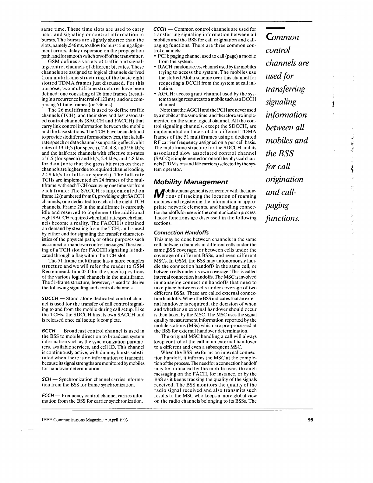
Figure
3.
GSMprotocol architecture,
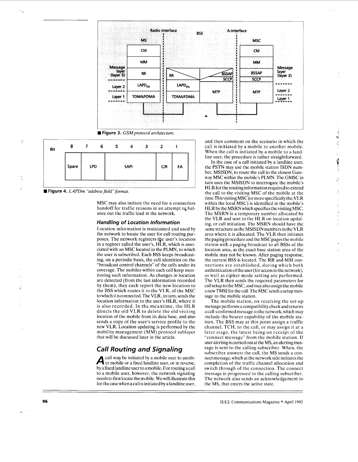
Figure
4.
LAPDm
“addressfield” format.
MSC may also initiate the need for a connection
handoff for traffic reasons in an attempt tq bal-
ance out the traffic load in the network.
Handling of Location Information
Location information is maintained and used by
the network to locate the user for call routing pur-
poses. The network registers tQe user’s location
in a register called the user’s, HLR, which is asso-
ciated with an MSC located in the PLMN, to which
the user is subscribed. Each
BSS
keeps broadcast-
ing, on a periodic basis, the cell identities on the
“broadcast control channels” of the cells under its
coverage. The mobiles within each cell keep mon-
itoring such information.
As
changes in location
are detected (from the last information recorded
by them), they each report the new location to
the
BSS
which routes it to the VLR, of the MSC
towhichit
isconnected.TheVLR,inturn,sendsthe
location information to the user’s HLR, where it
is also recorded. In the meantime, the HLR
directs the old VLR to delete the old visiting
location of the mobile from its data base, and also
sends a copy of the user’s service profile to the
new VLR. Location updating is performed by the
mobility management (MM) protocol sublayer
that will be discussed later in the article.
Call Routing and Signaling
call may be initiated by a mobile user to anoth-
A
er mobile
or
a fixed landline user,
or
in reverse,
by a fixed landline user to amobile.
For
routing acall
to a mobile user, however, the network signaling
needs to first locate the mobile. We will illustrate this
for thecasewhen acall isinitiatedby alandline user,
and then comment on the scenario in which the
call
is
initiated by a mobile to another mobile.
When the call is initiated by a mobile to a land-
line user, the procedure is rather straightforward.
In the case of a call initiated by a landline user,
the PSTN may use the mobile station ISDN num-
ber, MSISDN, to route the call to the closest Gate-
way MSC within the mobile’s PLMN. The GMSC in
turn uses the MSISDN to interrogate the mobile’s
HLRfor the routing information required to extend
the call to the visiting MSC of the mobile at the
time.Thisv,isiting MSC (or more specifically the,VLR
within the local MSC) is identified in the mobile’s
HLR by the MSRNwhich specifies the visiting MSC.
The MSRN is a temporary number allocated by
the VLR and sent to the HLR on location updat-
ing, or call initiation. The MSRN should have the
same structure as the MSISDN numbers in the VLR
area where it is allocated. The VLR then initiates
the paging procedure and the MSC pages the mobile
station with a paging broadcast to all
BSSs
of the
location area, as the exact base station area of the
mobile may not be known. After paging response,
the current
BSS
is located. The RR and MM con-
nections are established, during which both
authenticationoftheuser (for accesstothenetwork),
as well as cipher mode setting are performed.
The VLR then sends the required parameters
for
call setup to the MSC, and may also assign the mobile
a new TMSI for the call. The MSC sends asetup mes-
sage to the mobile station.
The mobile station, on receiving the set-up
message performs acompatibility check and returns
a call-confirmed message to the network, which may
include the bearer capability of the mobile sta-
tion. The
BSS
may at this point assign a traffic
channel, TCH, to the call, or may assign it at a
later stage, the latest being on receipt of the
“connect message” from the mobile station. If
user alerting is carried out at the MS, an alerting mes-
sage is sent to the calling subscriber. When, the
subscriber answers the call, the MS sends a con-
nect message, which at the network side initiates the
completion of the traffic channel allocation and
switch through of the connection. The connect
message
is
progressed to the calling subscriber.
The network also sends an acknowledgement to
the MS, that enters the active state.
96
IEEE
Communications
Magazine
April
1993
Authorized licensed use limited to: UNIVERSITI SAINS MALAYSIA. Downloaded on August 5, 2009 at 23:41 from IEEE Xplore. Restrictions apply.
I
I
I
Figure
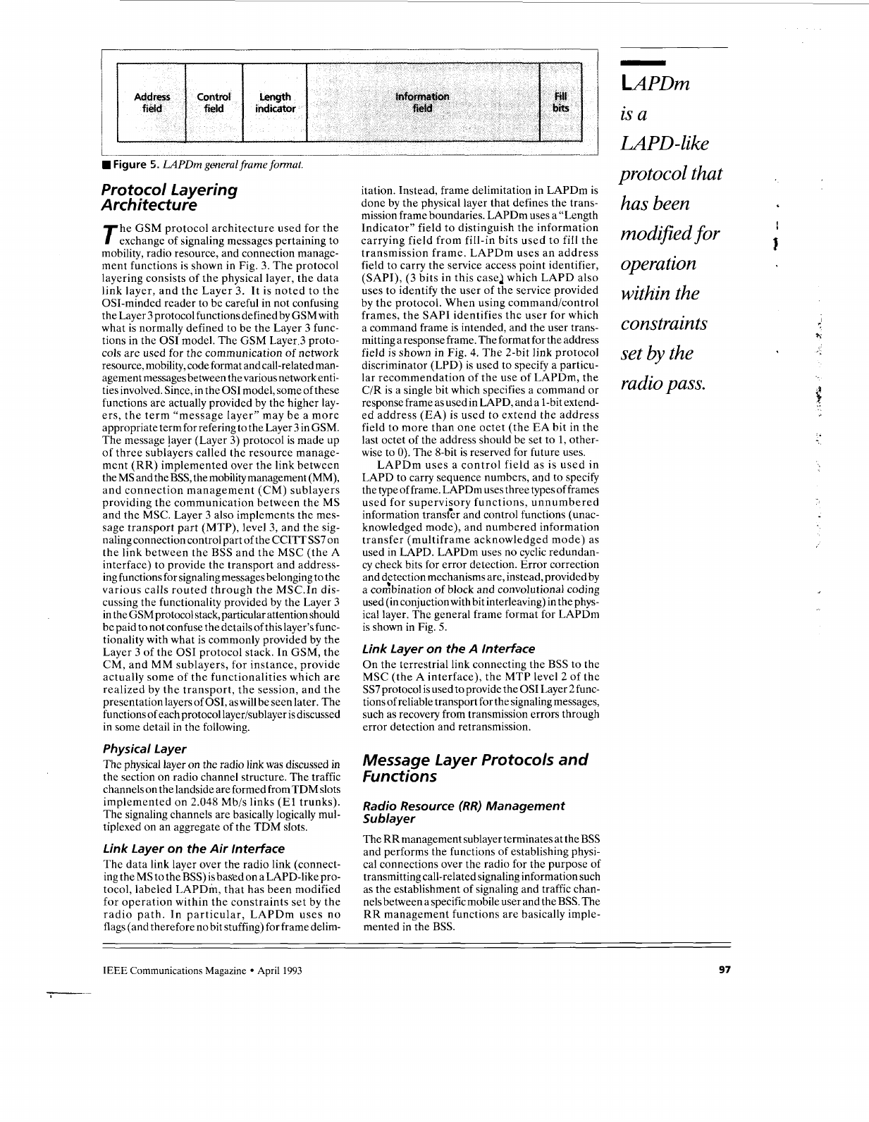
5.
LAPDm
general frame format.
Protocol layering
Architecture
he GSM protocol architecture used for the
T
exchange
of
signaling messages pertaining to
mobility, radio resource, and connection manage-
ment functions is shown in Fig.
3.
The protocol
layering consists of the physical layer, the data
link layer, and the Layer
3.
It is noted to the
OSI-minded reader to be careful in not confusing
the Layer
3
protocol functions defined by GSM with
what is normally defined to be the Layer
3
func-
tions in the
OS1
model. The GSM Layer
3
proto-
cols are used for the communication of network
resource, mobility, code format and call-related man-
agement messages between the various network enti-
ties involved. Since, in the
OS1
model, some
of
these
functions are actually provided by the higher lay-
ers, the term “message layer” may be a more
appropriate term for refering to the Layer
3
in GSM.
The message !ayer (Layer
3)
protocol is made
up
of three sublayers called the resource manage-
ment (RR) implemented over the link between
the MS and the
BSS,
the mobility management (MM),
and connection management (CM) sublayers
providing the communication between the MS
and the MSC. Layer
3
also implements the mes-
sage transport part (MTP), level
3,
and the sig-
naling connection control part of the CCIn SS7
on
the link between the
BSS
and the MSC (the A
interface) to provide the transport and address-
ing functions for signaling messages belonging to the
various calls routed through the
MSC.In
dis-
cussing the functionality provided by the Layer
3
in the GSM protocol stack, particular attention should
be paid to not confuse the details of this layer’sfunc-
tionality with what is commonly provided by the
Layer
3
of the
OS1
protocol stack.
In
GSM, the
CM,
and MM sublayers, for instance, provide
actually some of the functionalities which are
realized by the transport, the session, and the
presentation layers of
OSI,
as will be seen later. The
functions of each protocol layerisublayer is discussed
in some detail in the following.
Physical Layer
The physical layer on the radio link was discussed in
the section on radio channel structure. The traffic
channels
on
the landside are formed fromTDM slots
implemented on 2.048 Mb/s links
(El
trunks).
The signaling channels are basically logically mul-
tiplexed
on
an aggregate of the TDM slots.
Link Layer on the Air Interface
The data link layer over the radio link (connect-
ing theMS to
theBSS)isbas'edonaLAPD-like pro-
tocol, labeled LAPDm, that has been modified
for operation within the constraints set by the
radio path.
In
particular, LAPDm uses no
flags (and therefore
no
bit stuffing) for frame delim-
Address
Control
Length
Information
Fill
field field indicator field
bits
itation. Instead, frame delimitation in LAPDm is
done by the physical layer that defines the trans-
mission frame boundaries. LAPDm uses a “Length
Indicator” field to distinguish the information
carrying field from fill-in bits used to fill the
transmission frame. LAPDm uses an address
field to carry the service access point identifier,
(SAPI),
(3
bits in this case2 which LAPD also
uses to identify the user of the service provided
by the protocol. When using command/control
frames, the SAPI identifies the user for which
a command frame is intended, and the user trans-
mitting a response frame. The format for the address
field is shown in Fig. 4. The 2-bit link protocol
discriminator (LPD)
is
used to specify a particu-
lar recommendation of the use of LAPDm, the
C/R is a single bit which specifies a command or
response frame as used in LAPD, and a 1-bit extend-
ed address (EA)
is
used to extend the address
field to more than one octet (the EA bit in the
last octet of the address should be set to
1,
other-
wise to
0).
The 8-bit is reserved for future uses.
LAPDm uses a control field as is used in
LAPD to carry sequence numbers, and to specify
the type of frame. LAPDm uses three types of frames
used for supervisory functions, unnumbered
information transfer and control functions (unac-
knowledged mode), and numbered information
transfer (multiframe acknowledged mode) as
used in LAPD. LAPDm uses no cyclic redundan-
cy check bits for error detection. Error correction
and detection mechanisms are, instead, provided by
a conbination
of
block and convolutional coding
used (in conjuctionwith bit interleaving) in thephys-
ical layer. The general frame format for LAPDm
is shown in Fig.
5.
Link Layer on the
A
interface
On
the terrestrial link connecting the
BSS
to the
MSC (the A interface), the MTP level
2
of the
SS7protocol is used to provide the
OS1
Layer 2func-
tions of reliable transport for the signaling messages,
such as recovery from transmission errors through
error detection and retransmission.
Message layer Protocols and
Functions
Radio Resource (RR) Management
Sublayer
The RRmanagement sublayer terminates at the
BSS
and performs the functions of establishing physi-
cal connections over the radio for the purpose of
transmitting call-related signaling information such
as the establishment of signaling and traffic chan-
nels between a specific mobile user and the
BSS.
The
RR management functions are basically imple-
mented in the
BSS.
-
DPDm
is a
LA
PD -like
protocol that
has been
modified
for
operation
within the
constraints
set
by
the
radio pass.
h‘
f
IEEE
Communications Magazine April
1993
97
--
Authorized licensed use limited to: UNIVERSITI SAINS MALAYSIA. Downloaded on August 5, 2009 at 23:41 from IEEE Xplore. Restrictions apply.
-
Location
updating
is the
procedure
for
keeping
the network
informed
of
where
the mobile
is roaming.
Mobility Management Sublayer (MM)
The MM sublayer is terminated at the MSC and
the related messages from or to the MS are
relayed transparently in the BSS using the DTAP
process. The MM sublayer provides functions
that can be classified into three types of proce-
dures. These are called the MM specific procedures,
the MM common procedures, and the MM con-
nection-related procedures. These procedures
are discussed in the following.
MM Connection Related Procedures
These are the procedures used to establish, main-
tain, and release a MM connection between the MS
and the network (MSC) over which an entity of
the connection management (CM) sublayer can
exchange information with its peer. More than
one MM connection may be active at the same
time to serve multiple CM entities. Each CM
entitywithin the MS will have its
own
MM connection,
and each connection is identified by the protocol dis-
criminator, and a transaction identifier within the
related signaling messages exchanged. The trans-
action identifier is sort of analogous to the call
reference used by ISDN to identify signaling mes-
sages from different calls
on
the
D
channel. Thus
parallel calls can be supported by the same MS which
are then identified by a different value for the
transaction identifier parameter. Establishment
of a MM connection requires that no MM-specif-
ic procedure (discussed later) be active.
The MM connections provide services to the
different entities of the upper connection man-
agement (CM) sublayer which currently consist
of the call control (CC), the short messagc ser-
vices (SMS), and the call-independent supple-
mentaryservices
(SS).
AnMMconnection is initiated
by a CM service request message which identifies
the requesting CM entity and the type of service
required of the MM connection. The services
provided by the MM connections include such things
as enciphering (for privacy of user information), and
authentication (of the users-access to the network
and the service requested) which would be actual-
lyprovided by the presentation, and application lay-
ers in the OS1 framework. Each of these services
would involve the exchange of multiple messages
between the MS and the network before the required
MM connection is established and the requesting
entity within the CM sublayer is notified.
Mobility Management Specific
Procedures
The MM specific procedures do not set up an
MMconnection.Theycanonlybeinitiatedwhenno
other MM-specific procedure is running, andno MM
connection is established. These procedures
consist of location updating, and the IMSI attach
procedures. These are discussed in the following.
Location Updating
Location updating is the procedure for keeping the
network informed of where the mobile is roaming.
Location updating is always initiated by the mobile
station on either detecting that it is in a new loca-
tion area by periodically monitoring the location
information broadcast by the networkon the broad-
cast channel, and comparing it to the information
previously stored in its memory,
or
by receiving an
indication from the network that it is not known
in the VLR upon trying to establish an MM con-
nection. Anytime, the network updates the mobile's
location, it sends
itanupdated"temporarymobi1esub-
scriber identification" (TMSI), in ciphered mode,
which is stored in the MS and used for subsequent
mobile identification in paging and call initiating
operations. The purpose of using the TMSI as
opposed to the user's IMSI is to keep the subscriber's
identity confidential on the radio link. The
TMSI
has
no GSM- specific structure, and has significance only
within the location area assigned. The TMSI has
tobe combinedwith thelocation areaidentifier
(LAI)
to provide for unambiguous identification outside
the area where it is assigned.
lMSl Attach
zhe IMSI attach procedure is the complement of the
IMSI detach procedure, a function of the MM
common procedures (discussed later). Both of these
procedures are network options whose necessity
of usage are indicated through a flag in the sys-
tem information broadcast on the BCCH chan-
nel. The IMSI detachiattach procedures mark the
MS as detachediattached in the VLR (and option-
ally
in
the HLR) on MS power down or power up
or subscriber information module (SIM) removed or
inserted (The IMSI detach disables the location
updating function to prevent unnecessary signal-
ing overhead
on
the network). Any incoming
calls, in that case, are either rejected
or
forward-
ed as may be specified by the user). The IMSI is used
to indicate the IMSI as active in the network.
This procedure is invoked
if
an IMSI is activated
in
a MS (power up, or SIM insertion) in the cov-
erage area of the network,
or
an activated MS enters
the network's coverage area from outside. The IMSI
attach procedure is then performed only
if
the stored
location area at the time is the same as the one
being broadcast on the BCCH channel of the
serving cell. Otherwise, a normal location updat-
ing procedure is invoked regardless of whether the
network supports IMSI attachidetach procedures.
MM Common Procedures
The MM common procedures can be initiated at any
time while a dedicated radio channel exists between
the network and the MS. They do not se't up an
MM connection, but can be initiated during an
MM specific procedure,
or
while an MM connection
is in place. The MM Common procedures consist
of IMSI detach, TMSI reallocation, and authenti-
cationiidentification. These are discussed next.
lMSl Detach
The IMSI detach procedure is invoked by the mobile
station to indicate inactive status to the network.
No response
or
acknowledgement is returned to
the MS by the network on setting the active flag
for the IMSI.
The IMSI detach procedure is not started if at the
time a
MM-specific procedure
is active. In that case,
the IMSI detach procedure is delayed,
if
possible
until the MM-specific procedure is finished, oth-
erwise the IMSI detach request is omitted.
If at the time of a detach request, a radio con-
nection is in existence between the MS and the
network, the MM sublayer will release any ongo-
ing MM connections before the MM detach indi-
cation message is sent.
98
IEEE
Communications Magazine
April 1993
f
Authorized licensed use limited to: UNIVERSITI SAINS MALAYSIA. Downloaded on August 5, 2009 at 23:41 from IEEE Xplore. Restrictions apply.
TMSI Reallocation
The purpose of TMSI reallocation is to provide iden-
tity confidentiality. That is, to protect the user
from being identified and located by an intruder.
This procedure must be performed at least at each
change of the MSC coverage area. Reallocation
in any other case is left to the network operator.
If the TMSI provided by a mobile station is
unknown in the network; for instance, in the case
of a data base failure, the MS has to provide its
IMSI on request from the network. In this case
the identification procedure has to be performed
before the TMSI procedure can be initiated.
Authentication
The purpose of the authentication procedure is
to let the network verify the identity provided by
the userwhen requested, and to provide a new cipher-
ing key to the mobile station. The caseswhen authen-
tication procedures should be used are defined in
GSM Recommendation 02.09. The authentica-
tion procedure is always initiated and controlled
by the network.
Identification
This procedure is used by the network to request
a mobile station to provide specific identification
parameters to the network, such as the user’s
international mobile subscriber or equipment
identifiers(IMS1 or IMEI). The mobile station should
be ready to respond to an identity request mes-
sage at any timewhile RRconnection exists between
the mobile and the network.
Connection Management
Sublayer (CM)
he CM sublayer terminates at the MSC and con-
T
tains entities that currently consist of CC includ-
ing call-related supplementary services, SMS, and
call independent supplementary services support
(SS).
Once a MM connection has been established,
the CM can use it for information transfer. The
CCentityuses the CCI’ITQ.931 protocol, withminor
modifications, for the communication of call con-
trol-related messages between the MS and the MSC.
The SMS is a GSM-defined service that providesfor
speedy packet mode (“connectionless”) commu-
nication of messages up to 140 bytes between the MS
and a third party service center. These messages can
be sent
or
received by the mobile stationwhile avoice
or data call is in the active or inactive state. It is accept-
able, however,
if
the service is aborted while a
call is in a transitional state such as handover or busy-
to-idle. The service center is responsible for the
collection, storage, and delivery of short mes-
sages, and is outside the scope of GSM.
BSS
Application Part
(BSSAP)
he BSS, in addition to providing thechannel switch-
T
ing and aerial functions, performs radio resource
management, and intenvorking functions between
the data link protocols used
on
the radio and the
BSS-MSC side for transporting signaling-related
messages. These functions are provided by the
BSS Management Application Process (BSSMAP),
and the Direct Transfer Application Process (DTAP).
The BSSMAP is used to implement all proce-
dures between the MSC and the BSS that require
interpretation and the processing of information
related to single calls, and resource manage-
ment. Basically, the BSSMAP is the process with-
in the BSS that controls radio resources in
response to instructions from the MSC (in that
sense, the BSSMAP represents the RR sublayer
to the MSC).
For
instance, the BSSMAP is used
in the assignment and switching
of
radio channels
at call setup, and handover processes.
The DTAP process is used for the transparent
transfer
of
MM/CM signaling messages between the
MS and the MSC. That is, the DTAP function
provides the transport level protocol intenvorking
function for transferring Layer 3 signaling messages
from and to the MS to and from the MSC with-
out any analysis of the message contents.
Signaling Transport Protocols
he CCITT
SS7
MTP and SCCP protocols are
T
used to implement both the data link and the
Layer 3 transport functionsfor carrying the call con-
trol and mobility management signaling messages
on
the BSS-MSC link. The MM and CM sublayer
signaling information from the mobile station is rout-
ed over signaling channels (such as the DCCH,
SACCH, FACCH) to the BSS from where they are
transparently relayed through the DTAP process
to an SCCP, of CCITT
SS7
type logical channel,
assigned for that call, on the BSS-MSC link for trans-
mission to the peer CC entity in the MSC for pro-
cessing. Similarly, any call signaling information
initiated by the MSC
on
the SCCP connection is
relayed through the DTAP process in the BSS to the
assigned signaling’ channel, using the LAPDm
datalink protocol, for delivery to the mobile station.
The interworking between the Layer 2 proto-
col on the radio side and the
SS7
on
the BSS-MSC
link is provided by a distribution data unit within
the information field of the SCCP. These param-
eters a’re known as the discrimination, and the data
link connection identifier (DLCI) parameters.
The discrimination parameter (currently dedicat-
ed one octet) uses a single bit to address a message
either to the DTAP or the BSSMAP processes. The
DLCIparameter (sized one octet) is made up of two
subparameters that identify the radio channel type
(such as the DCCH, SACCH, FACCH), and the
“Service Access Point Interface”(SAP1) value (in the
LAPDm protocol) used for the message on the radio
link. The SCCP provides for the logical multiplexing
of signaling information from different calls onto
the same physical channel (such as a single 64 kb/s
slot of a 2.048
Mb/s
El
trunk)
on
the BSS-MSC link.
For
each call supported by a BSS, an SCCP logical
connection is established on the BSS-MSC link. Any
information pertaining to a specific call flows through
its associated SCCP connection and that is how
signaling information exchange pertaining to
different calls are identified in the
BSS
or MSC.
The connectionless service mode of the SCCP
is also supported for the transfer of OA&M relat-
ed messages as well as BSSMAP messages that
do not pertain to any specific call (Note that BSSMAF’
messages pertaining to specific calls, such as hand-
off messages, are transmitted using the SCCP
connection established for the call). The SCCP rout-
ing function uses the Subsystem Number
(SSN)
-
The authenti-
cation proce-
dure allows
the network
to veri8 the
identity pro-
vided
by
the
user ,when
requested,
and topro-
vide a new
ciphering key
to the mobile
station.
i
I
h‘
Q
IEEE
Communications Magazine April
1993
-
~.
99
Authorized licensed use limited to: UNIVERSITI SAINS MALAYSIA. Downloaded on August 5, 2009 at 23:41 from IEEE Xplore. Restrictions apply.
-
The optimum
size
for
the
paging area
is
determined
by
a proper
balance
between the
costs
of
paging and
the costs
of
location
updates.
in the Service Information Octet (SIO) within the
MTP level
3
message to distinguish messages
addressed to the OA&M function from those
addressed to either the DTAP or the BSSMAP appli-
cation parts. The high-level address translation capa-
bility of the SCCP, known as global title translation,
may then be used to provide additional address-
ing capabilities such as use of E. 164 numbering
for addressing different OA&M entities. The
global title translation feature of the SCCP also pro-
vides the MSC the capability to address signaling
messages to remote MSCs that may be located in
a different PLMN.
The interworking functions between the CM, MM
and BSSMAP entities and the corresponding
entitiesof the
SS7
(i.e., the ISDN-UP), MAP, SCCP,
and the transactions capabilities application part
(TCAP) is provided by the MSC.
Paging
and present it in some logical and well-related
format. I have tried my best, however, to achieve this
goal in this article.
This article was meant to provide a concise, brief,
but adequately detailed description of the GSM sys-
tem and protocol architecture that can serve as a
quick, rather self-contained conceptual frame-
work for extending and relating the mobility-specific
functions of the next generation personal com-
munication networks to the GSM network functions,
and the protocols used to achieve them. Finally, a
list of references have been provided for any
more detailed information on the issues addressed
in the article.
Acknowlegements
The author would like to thank Bomber Bishop
and
David Leeper from Motorola, and Prapeep
Sherman from AT&T for their careful reading of
the original manuscript and for providing useful
comments.
i
1
aging messages for mobiles are sent via the
P
BSSMAP'to the BSS as a connectionless mes--
sage through the SCCP/MTP. The paging mes-
sage may include the mobile's IMSI in order to
allow derivation of the paging population num-
ber. A single paging message transmitted to the BSS
may contain a list of cells in which the page is to be
broadcast. The larger the paging area is defined, the
lower the frequency of location updatesand hence
the associated traffic overhead on the network.
On the other hand, large paging areas result in
increased use of transmitting power as well as the
radio resources (channels). Therefore, the optimum
size for the paging area (location area) is detem-
ined by a proper balance between the costs-of
paging and the costs of location updates.
The paging messages received from the MSC are
stored in the BS, and corresponding paging messages
are transmitted over the radio interface at the appro-
priate time. Each paging message relates to only one
mobile station and the BSS has to pack the pages into
the relevant 04.08 paging messagz(inc1ude Layer
3
information). Once a paging message is broad-
cast over the radiochannel(s), if a response message
is received from the mobile, the relevant signaling
connection is set up towards the MSC and the
page response message is passed to the MSC.
Summary Remarks
he description of the GSM network functions,
T
system architecture and protocols are spread
over a large number of GSM do.cuments, each
of
which contains many details with some of the crit-
ical issues and highlights covered within those details.
Therefore, it is not an easy task to extract out
some of the crucial concepts and design specifics,
References
[11 W.C.Y. Lee, "Spectrum Efficiencyin Cellular,"lEE€Trans on Veh. Tech.,
[21 W.C.Y. Lee, "Spectrum Efficiency and Digital Cellular."38th
/E€€
I31 GSM Recommendation 04.03, "MS-855 Interface: Channel Struc-
[41 GSM Recommendation 05.01, "Physical Link Layer on the Radio
I51 GSM Recommendation 05.02, "Multiplexing and Multiple Access
[61 Conference Proceedings. Digital Cellular Radioconference, Hagen FRG,
[71 GSM Recommendation002.02, "Bearer Services Supported bya PLMN."
181 GSM Recommendation 09.01, "General Aspects on PLMN Inter-
(91 GSM Recommendation 03.04, "Signaling Requirements Related to
[lo1 GSM Recommendation 08.02, "855-MSC Interface-Interface Principles."
[l 11 GSM Recommendation
08
04, "BSS-MSC Layer 1 Specifications."
11 21 GSM Recommendation
08.06,
"
Signaling Transport Mechanisms
[131 GSM Recommendation 09.02, "Mobile Application Part (MAP)
I141 GSM Recommendation
08.08.
"855-MSC Layer
3
Specifications."
[151 GSM Recommendation 04.08, "Mobile Radio Interface-Layer
3
vol.
38. no. 2, May 1989.
Veh. Tech. Conf. Records,
pp.643.
June 1988..
tures and Access Capabilities."
Path" (General Description).
on the Radio Path."
Oct. 1988.
working."
Routing of Calls to Mobile Subscribers."
for BSS-MSC Interface."
Specification.''
Specifications."
Biography
MO€
RnhNFMn
received
a
B
5
oegree in engmeer ng science
from
the
Jniversity
of
Kentucky at -exington in 1978 with honors He received
the M
5
degree dnd the more advance0 engineermg degree in Avion
ics
from
MI1 n 1981
From
1983
to
1984 he tabght and stbdied
com
mbnication scjencesat Northeastern Universdyfrom which healso receivea
the Engineer degree m electrical and computer engineer ng with Ph
D
eve coursework He worked as a senior communlcation deslgn eng
neer at nf net in Andover. Mass
from
1984 to 1985 where he designed
thed gitalslgna
processingfirmwarefora4800baud
modem
From
1985
to
1989
heworkeoasamemberofthetechnicalstaff
atGTE Laboratories
ana developed a new system architecture for fast packet switching
oasedon theslotted ring concept (pbbtished inl€EE TransaciionsonCom
munrcations April 1990) From 1989
to
1991 ne workea
as
a prNnci
pa engineerat
Arinconthedesignandanalys
sofatrlgroundcommun cation
networks for the airlines industry He pned Motorola as a princlpa
communlcatton engineer in 1992, and since has been working on the
r
d bm satellite prolect
His
mterests nclude wireless networks com
mbn catnon systems and digital slgnal processing
h
100
IEEE
Communications Magazine
April
1993
-
Authorized licensed use limited to: UNIVERSITI SAINS MALAYSIA. Downloaded on August 5, 2009 at 23:41 from IEEE Xplore. Restrictions apply.
