1
818 West Diamond Avenue - Third Floor, Gaithersburg, MD 20878
Phone: (301) 670-4784 Fax: (301) 670-9187 Email: [email protected]
Website: https://www.gl.com
1
Global System for Mobile Communications (GSM) Protocol
Analysis and Simulation

2
What is GSM ?
• Global System for Mobile (GSM) is a second generation cellular standard developed to cater voice
services and data delivery using digital modulation
Based on ETSI standards
• GSM is a digital system with an over-the-air bit rate of 270 kbps. The frequency range is 1,850 to 1,990
MHz (mobile station to base station)
• GSM utilizes the time or frequency division multiple access (TDMA / FDMA) concept
• GSM uses Gaussian minimum shift keying (GMSK)
• GSM specifications follow the stipulations for the bottom three layers (physical, data link, & network
layers) of the OSI model

3
Advantages of GSM over Analog System
• Capacity increases
• Reduced RF transmission power and longer battery life
• International roaming capability
• Better security against fraud (through terminal validation and user authentication)
• Encryption capability for information security and privacy
• Compatibility with ISDN, leading to wider range of services

4
GSM Specifications
• GSM 900
➢ Mobile to BTS (uplink): 890-915 Mhz
➢ BTS to Mobile(downlink):935-960 Mhz
➢ Bandwidth : 2* 25 Mhz
• GSM 1800
➢ Mobile to BTS (uplink): 1710-1785 Mhz
➢ BTS to Mobile(downlink) 1805-1880 Mhz
➢ Bandwidth : 2* 75 Mhz
➢ PCS 1900 or DCS 1900
➢ The only frequency used in the United States and Canada for GSM
5
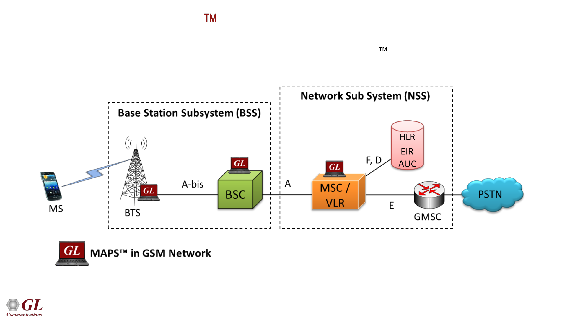
GSM System Architecture
• Network Switching Subsystem (NSS) – Its main components
include:
➢ Mobile Switching Center (MSC)
➢ Home Location Register (HLR)
➢ Visitor Location Register (VLR)
➢ Authentication Center (AUC)
➢ Equipment Identity Register (EIR)
• Base Station Subsystem (BSS) – Its main components include:
➢ Base Transceiver Station (BTS)
➢ Base Station Controller (BSC)
• Mobile Station (MS) – Its main components include:
➢ Mobile Equipment (ME)
➢ Subscriber Identity Module (SIM)
• Operation SubSystem (OSS) – Its main components include:
➢ Operations and Maintenance Center (OMC)
➢ Network Management Center (NMC)
➢ Administration Center (ADC)
6
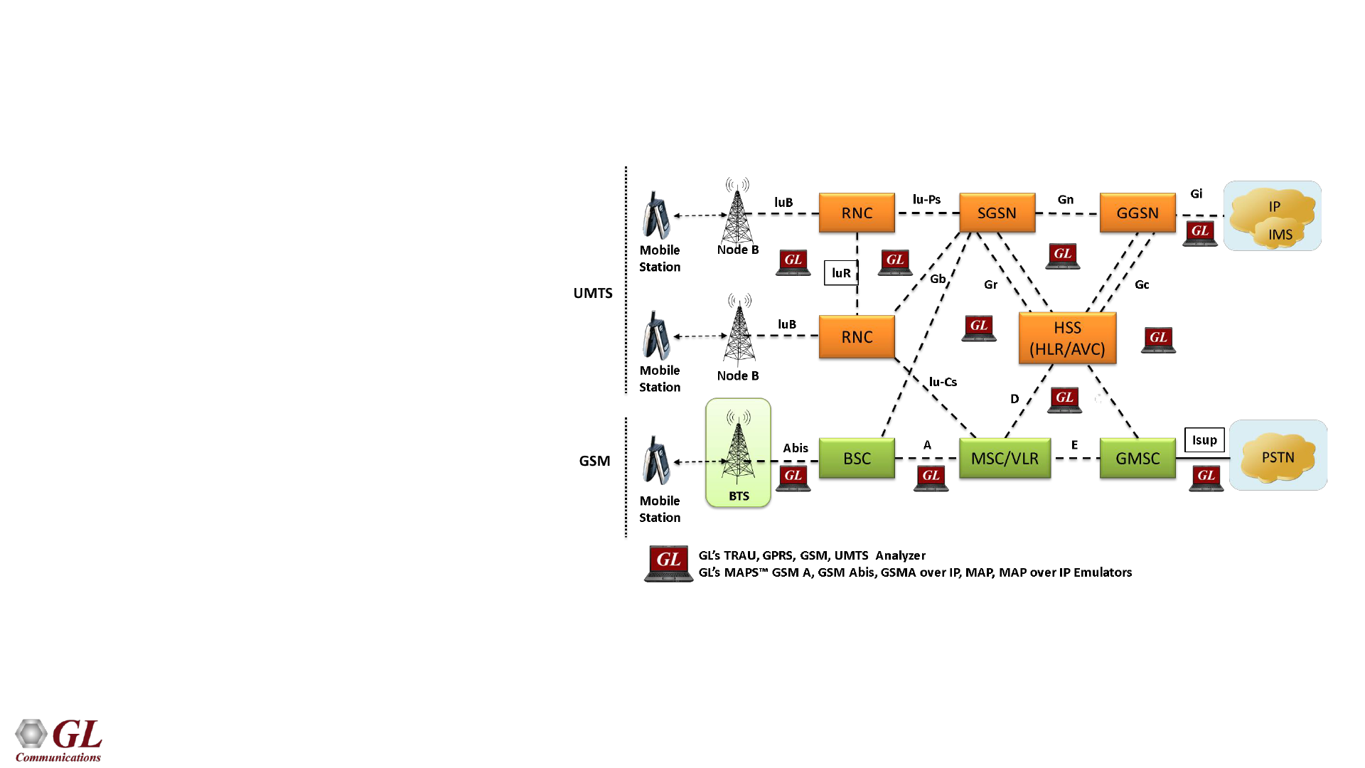
T1 E1 Analyzer Hardware Platforms
7
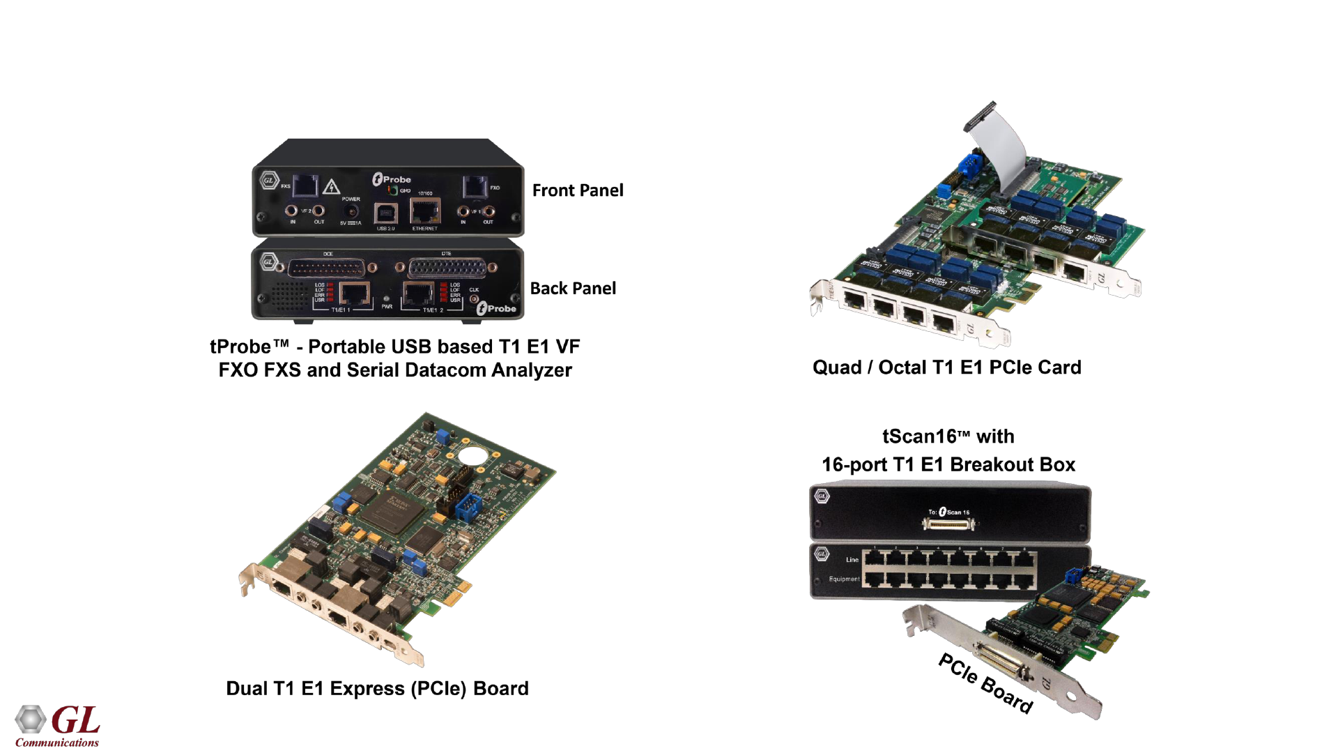
TDM mTOP Solutions
mTOP tProbe FXO FXS Dual UTA
1U tProbe with FXO and FXS1

8
Base Station Subsystem (BSS)
• Base Transceiver Station (BTS)
➢ Encodes, encrypts, multiplexes, modulates and feeds the RF signals to the antenna.
➢ Frequency hopping
➢ Communicates with Mobile station and BSC
➢ Consists of Transceivers (TRX) units
▪ Base Station Controller (BSC)
➢ Manages Radio resources for BTS
➢ Assigns Frequency and time slots for all MS’s in its area
➢ Handles call set up
➢ Transcoding and rate adaptation functionality
➢ Handover for each MS
➢ Radio Power control
➢ It communicates with MSC and BTS

9
Network Switching Subsystem (NSS)
• Carries out switching functions and manages the communications between mobile phones and the PSTN
• Allows mobile phones to communicate with each other
• Includes the following elements –
➢ Mobile Switching Center (MSC) –
– Capable of receiving a short message from a Service Center (SC)
– Interrogating an HLR for routing information and message waiting data, and delivering the short
message to the MSC of the receiving MS
➢ Home Location Registers (HLR) –
– Connection of mobile subscribers and definition of corresponding subscriber data
– Maintenance of a database of mobile subscribers and corresponding subscriber data
– Subscription to basic services
– Registration/deletion of supplementary services
– Activation/deactivation of supplementary services
.

10
Network Switching Subsystem (NSS)
➢Visitor Location Registers (VLR) –
▪ Functions for setting up and controlling calls, including supplementary services
▪ Functions for handling speech path continuity for moving subscribers (handover)
▪ Functions for updating mobile subscribers’ location (location updating and location canceling) in the different location
registers
▪ Functions for updating mobile subscriber data
➢Authentication Center (AUC) -
▪ a RANDom number (RAND)
▪ a Signed RESponse (SRES)
▪ a Ciphering Key (Kc)
• generates user specific authentication parameters on request of a VLR authentication parameters used for
authentication of mobile terminals and encryption of user data on the air interface within the GSM system
➢Equipment Identity Register (EIR)
• registers GSM mobile stations and user rights stolen or malfunctioning mobile stations can be locked and sometimes
even localized

11
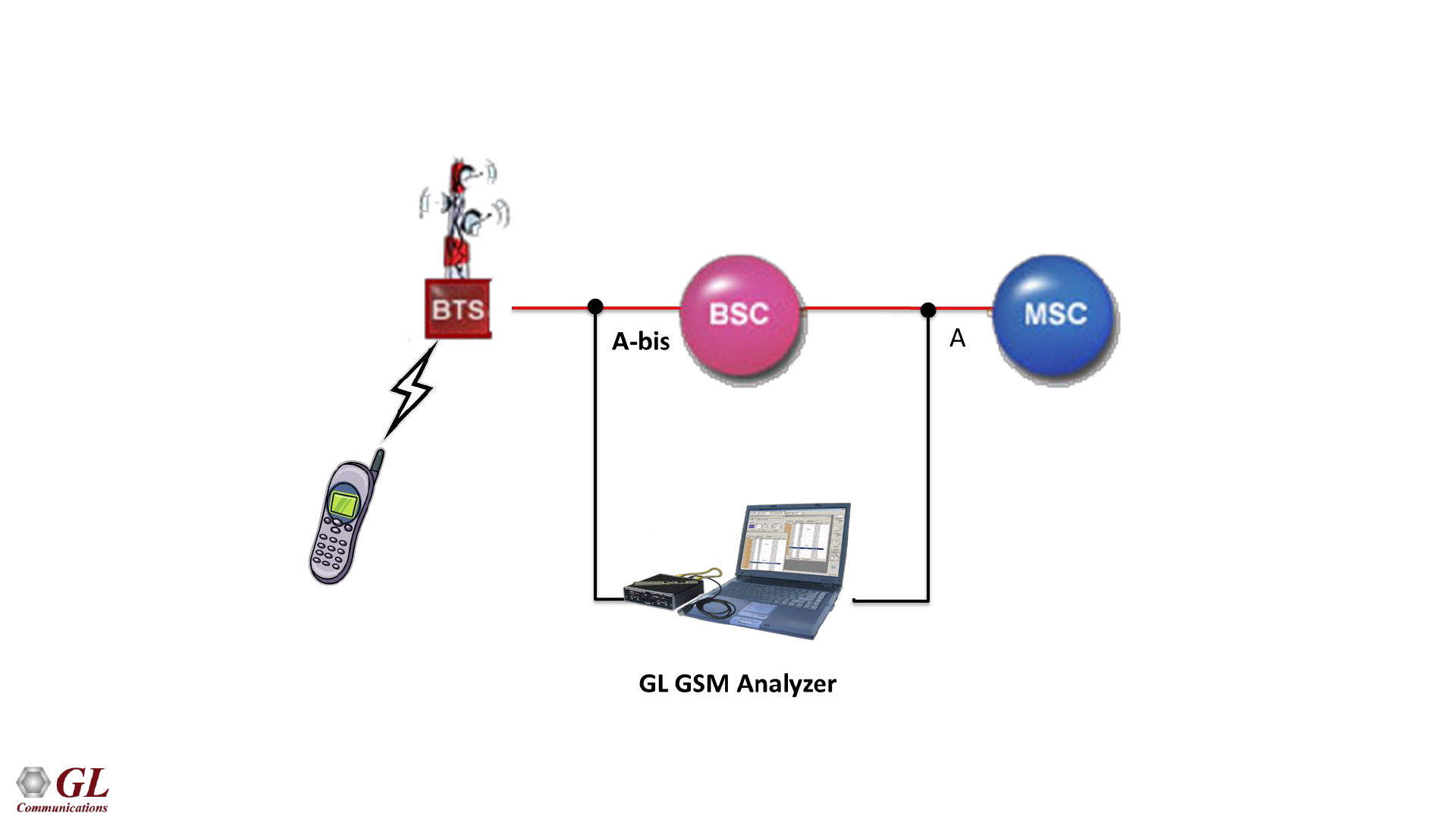
GSM Signaling Interfaces
• Um - Air interface used for exchanges between a MS and a BSS
• Abis - Abis interface allows control of the radio equipment and radio frequency allocation in the BTS
• A - A interface is between the BSS and the MSC. The A interface manages the allocation of suitable radio
resources to the MSs and mobility management
• B - The B interface between the MSC and the VLR uses the MAP/B protocol. Most MSCs are associated
with a VLR, making the B interface "internal"
• C - The C interface is between the HLR and a GMSC or a SMS-G. MAP/C protocol over the C interface is
used to obtain the routing information required to complete the call
• D - The D interface is between the VLR and HLR, and uses the MAP/D protocol to exchange the data
related to the location of the MS and to the management of the subscriber

12
Interfaces
• E - The E interface interconnects two MSCs. The E interface exchanges data related to handover between
the anchor and relay MSCs using the MAP/E protocol
• F - The F interface connects the MSC to the EIR, and uses the MAP/F protocol to verify the status of the
IMEI that the MSC has retrieved from the MS
• G - The G interface interconnects two VLRs of different MSCs and uses the MAP/G protocol to transfer
subscriber information, during e.g. a location update procedure
• H - The H interface is between the MSC and the SMS-G, and uses the MAP/H protocol to support the
transfer of short messages
• I - The I interface (not shown in Figure 1) is the interface between the MSC and the MS. Messages
exchanged over the I interface are relayed transparently through the BSS
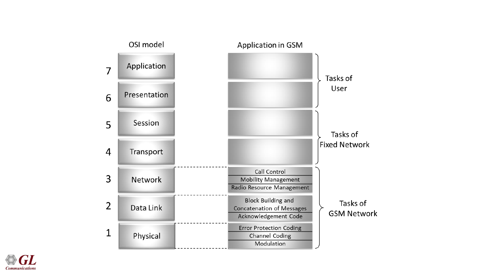
13
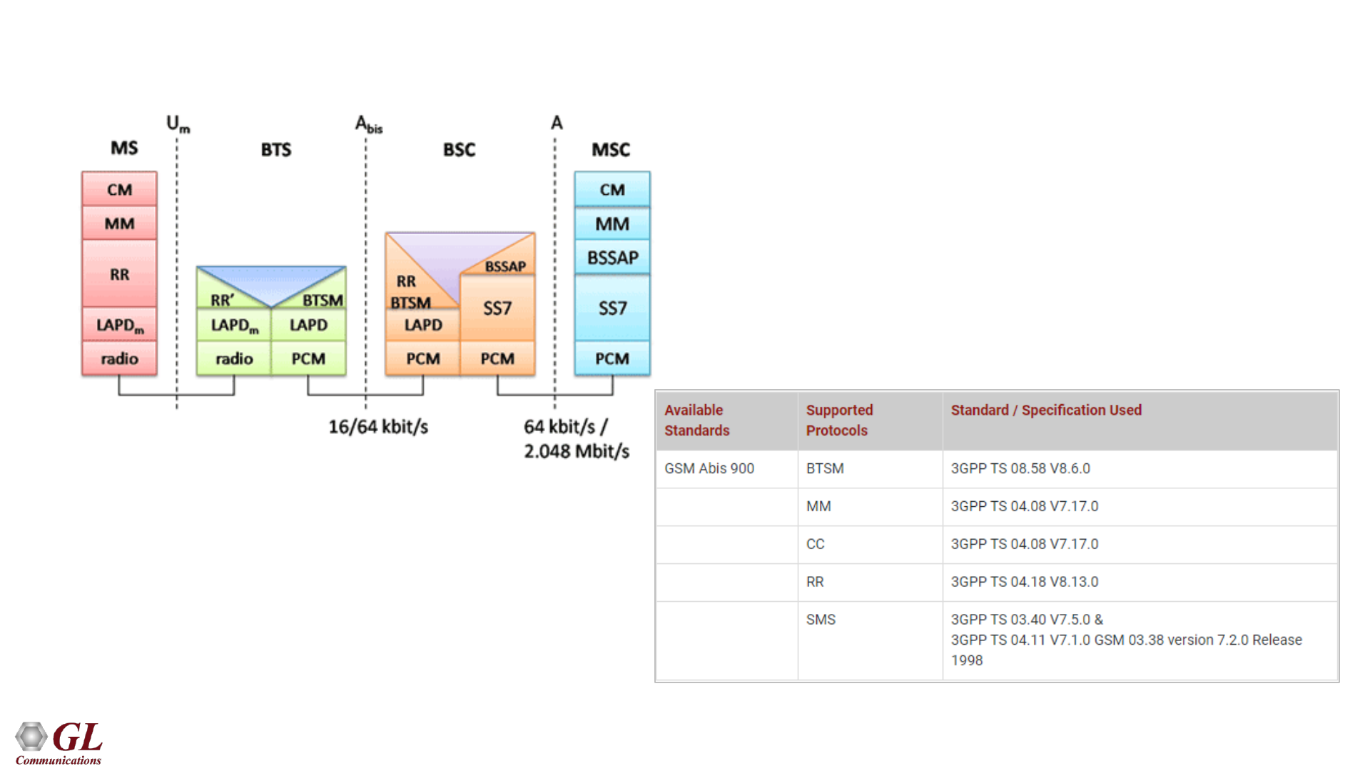
Comparing GSM layers with OSI model
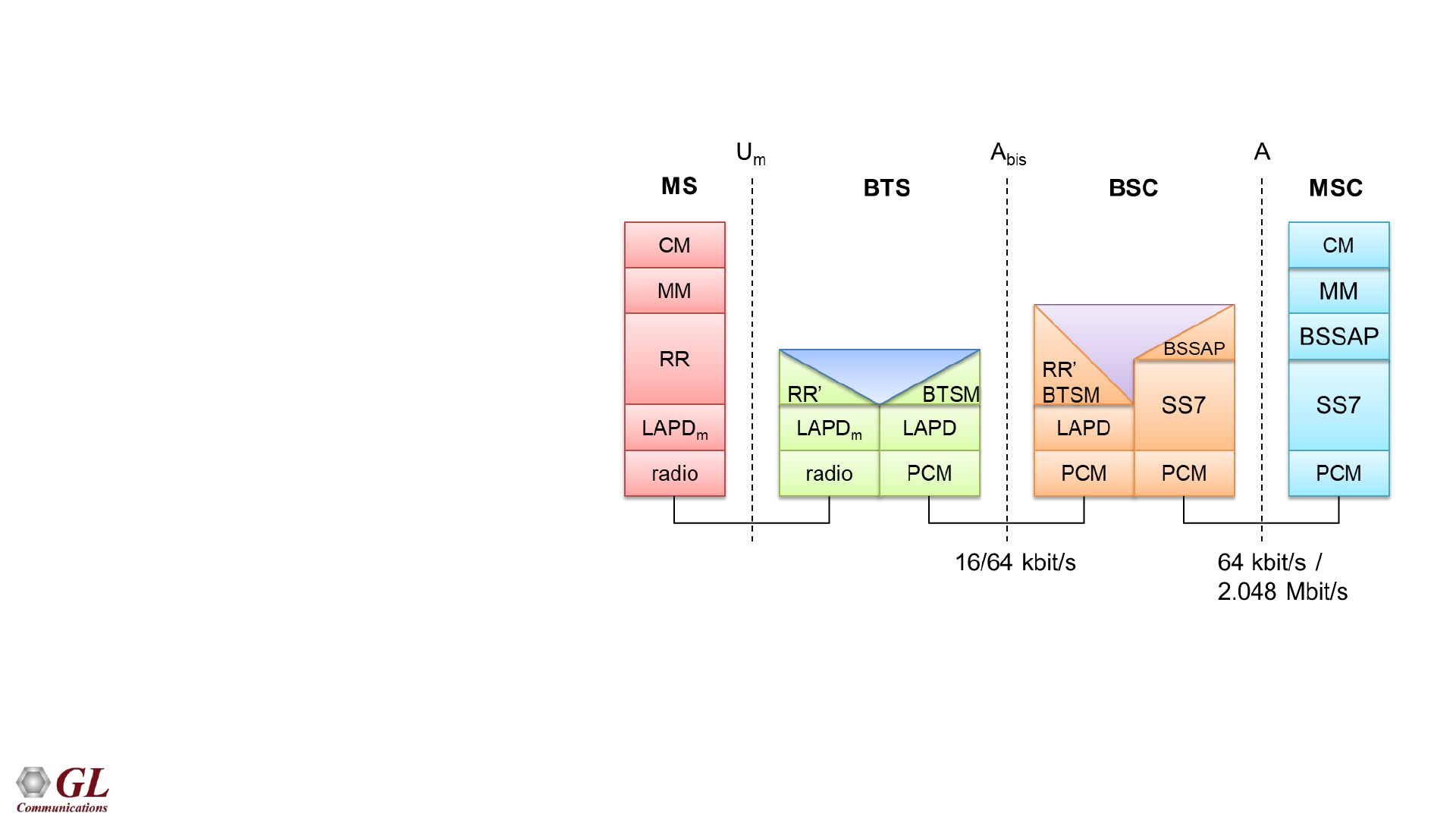
14
GSM Protocol Layers for Signaling
• CM – Connection Management
• MM – Mobility Management
• RR – Radio Resource Management
• LAPDm – Link Access Protocol D-
Channel Modified
• BSSMAP Base Station Subsystem
Mobile Application Part
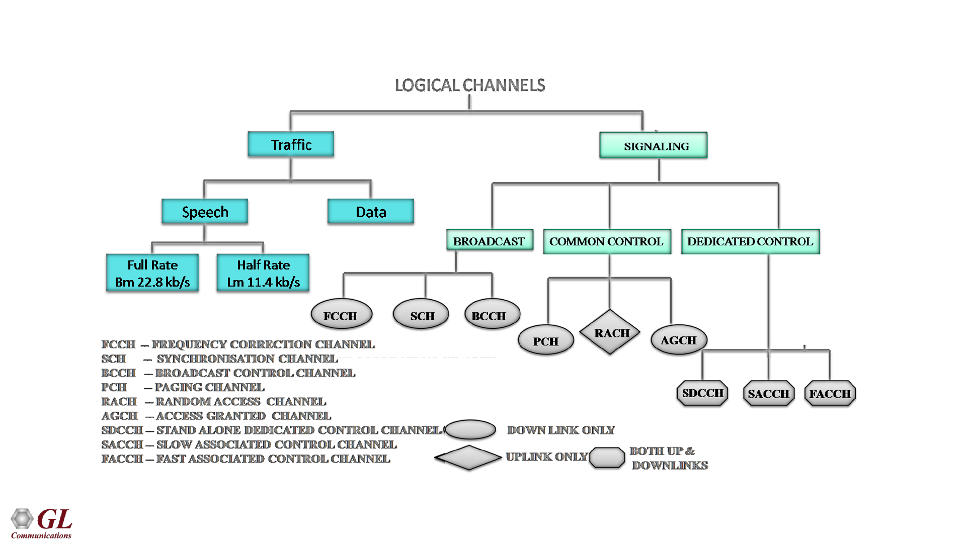
15
Logical Channels

16
GSM Services
• Tele-services Telecommunication services that enable voice communication, fax transmission via mobile
phones
➢Offered services - Mobile telephony, Emergency calling
• Bearer or Data Services Include various data services for information transfer between GSM and other
networks like PSTN, ISDN etc. at rates from 300 to 9600 bps
➢Offered services - Short Message Service (SMS), Unified Messaging Services(UMS), Group 3 fax,
Voice mailbox, Electronic mail
• Supplementary Service
➢Call related services - Call Waiting, Call Hold, Call Barring, Call Forwarding, Multi Party Call
Conferencing, CLIP , CLIR , CUG
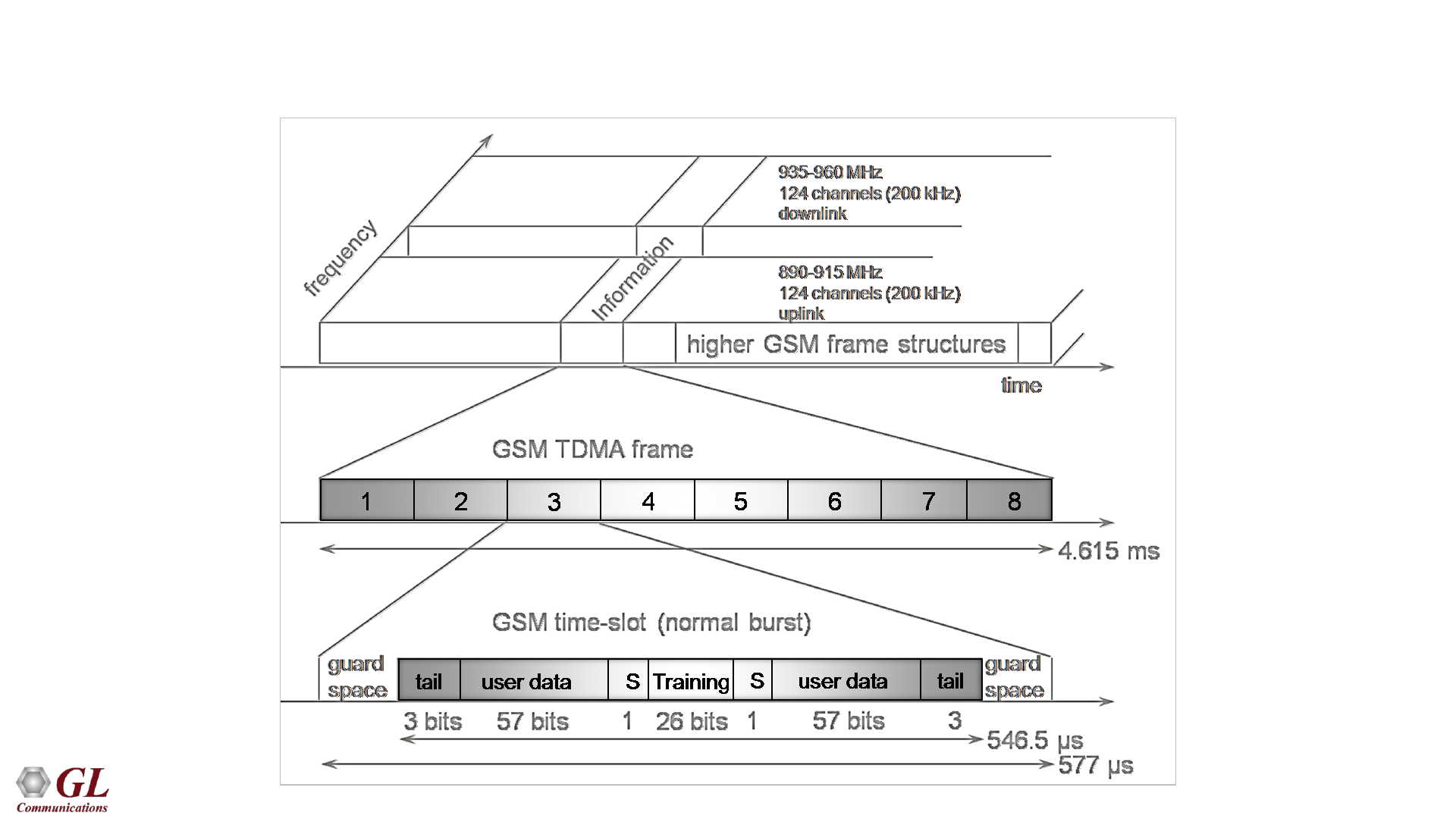
17
GSM Frame Structure
18
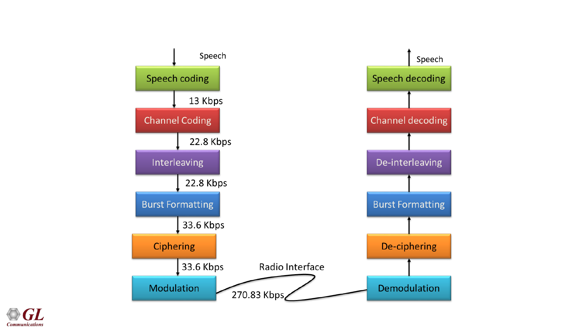
GSM Operation
19
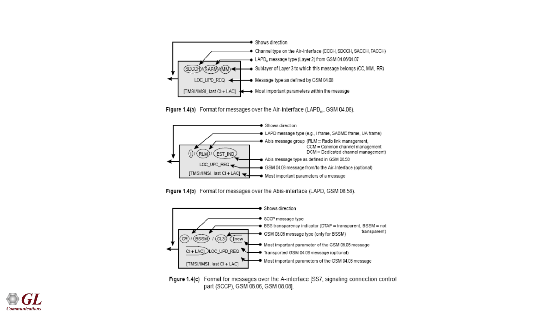
Message Format
20
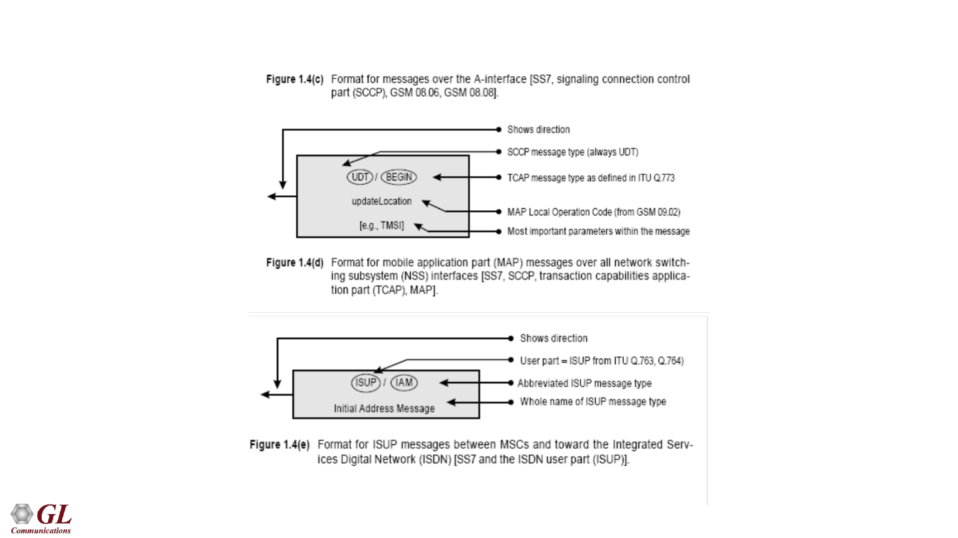
Message Format
21
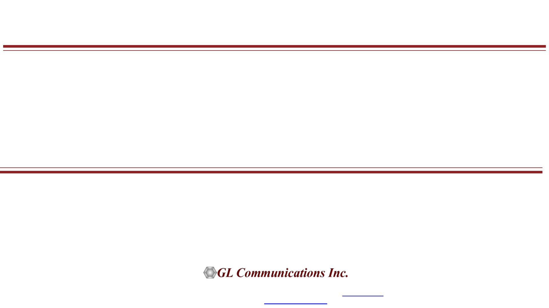
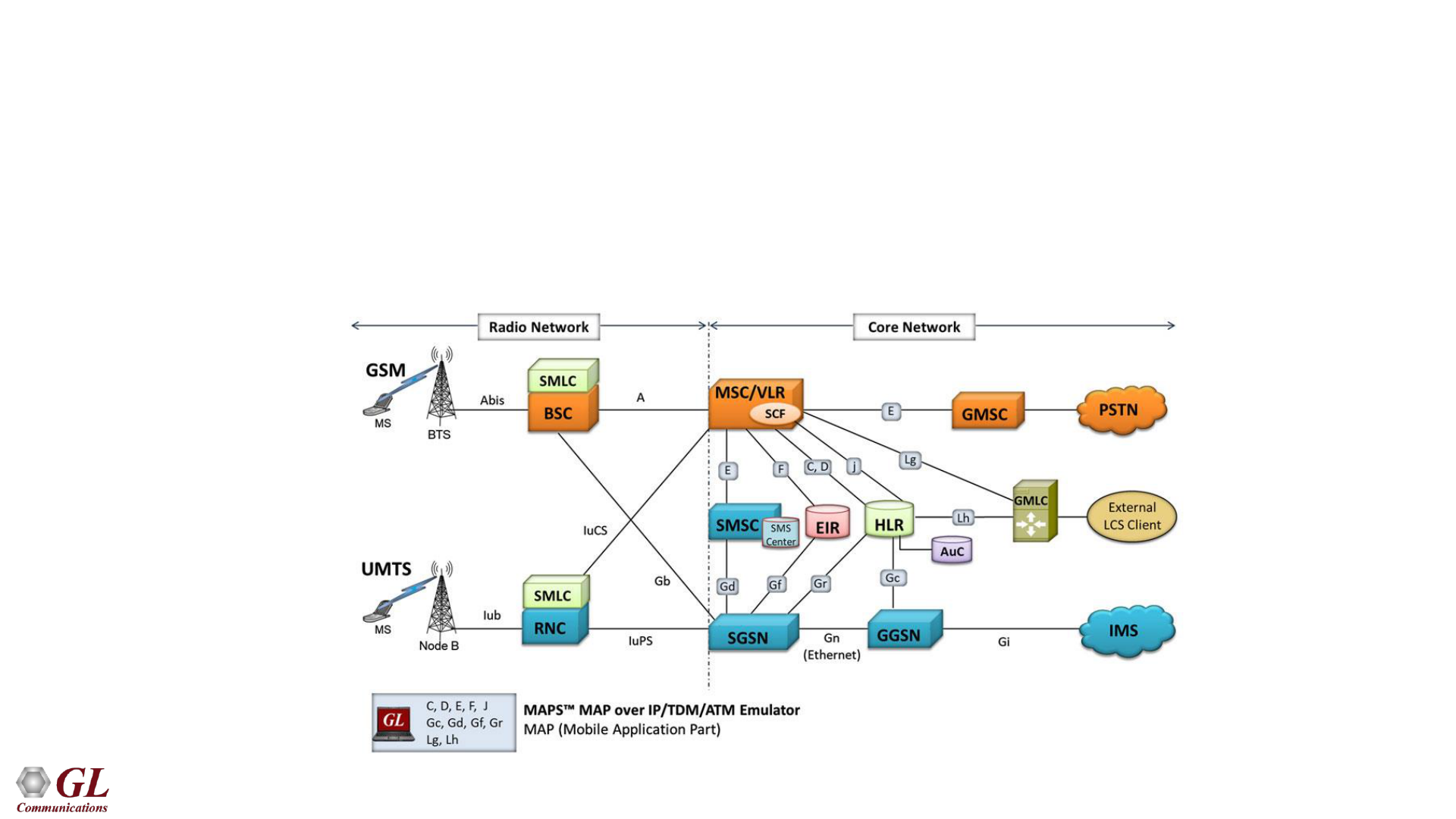
Mobile Application Part (MAP) Signaling
for GSM and UMTS Networks
• The components in the MSCs such as HLR, AuC, EIR, and the VLR are interconnected by MAP
signaling
• MAP uses Signaling System No. 7 (SS7) as carrier and provide services to mobile phone users such
as roaming, call handling, non-interruptive handover, and more

22
Mobile Application Part (MAP) Signaling
• Some of the GSM/UMTS Circuit Switched interfaces transported over SS7 using MAP signaling are:
➢B -> MSC to VLR
➢C -> MSC to HLR
➢D -> VLR to HLR
➢E -> Inter-MSC handover
➢F -> MSC to EIR
• There are also several GSM/UMTS PS interfaces transported over SS7 using MAP signaling :
➢Gr -> SGSN to HLR
➢Gd -> SGSN to SMS-C
➢Gc -> GGSN to HLR
➢Gf -> SGSN to EIR
23
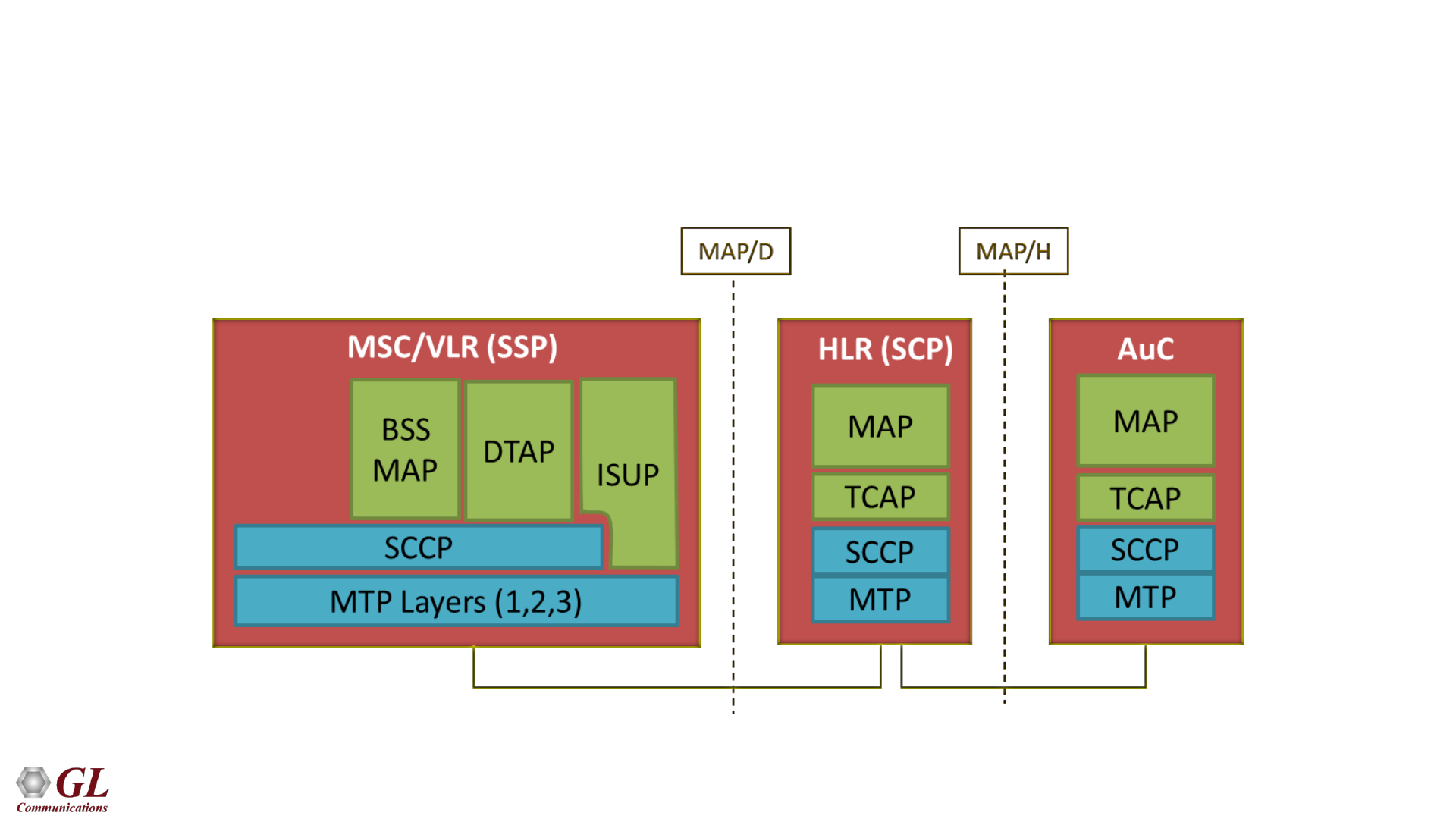
Typical Protocol Stack
• The Mobile Application Part (MAP) is the application-layer protocol that resides on top of the SS7
protocol stack, and is carried within Transaction Capabilities Application Part (TCAP) messages

24
GL's GSM Protocol Analysis and Simulation
25
GL's GSM Analyzer
26
GL's GSM Analyzer

27
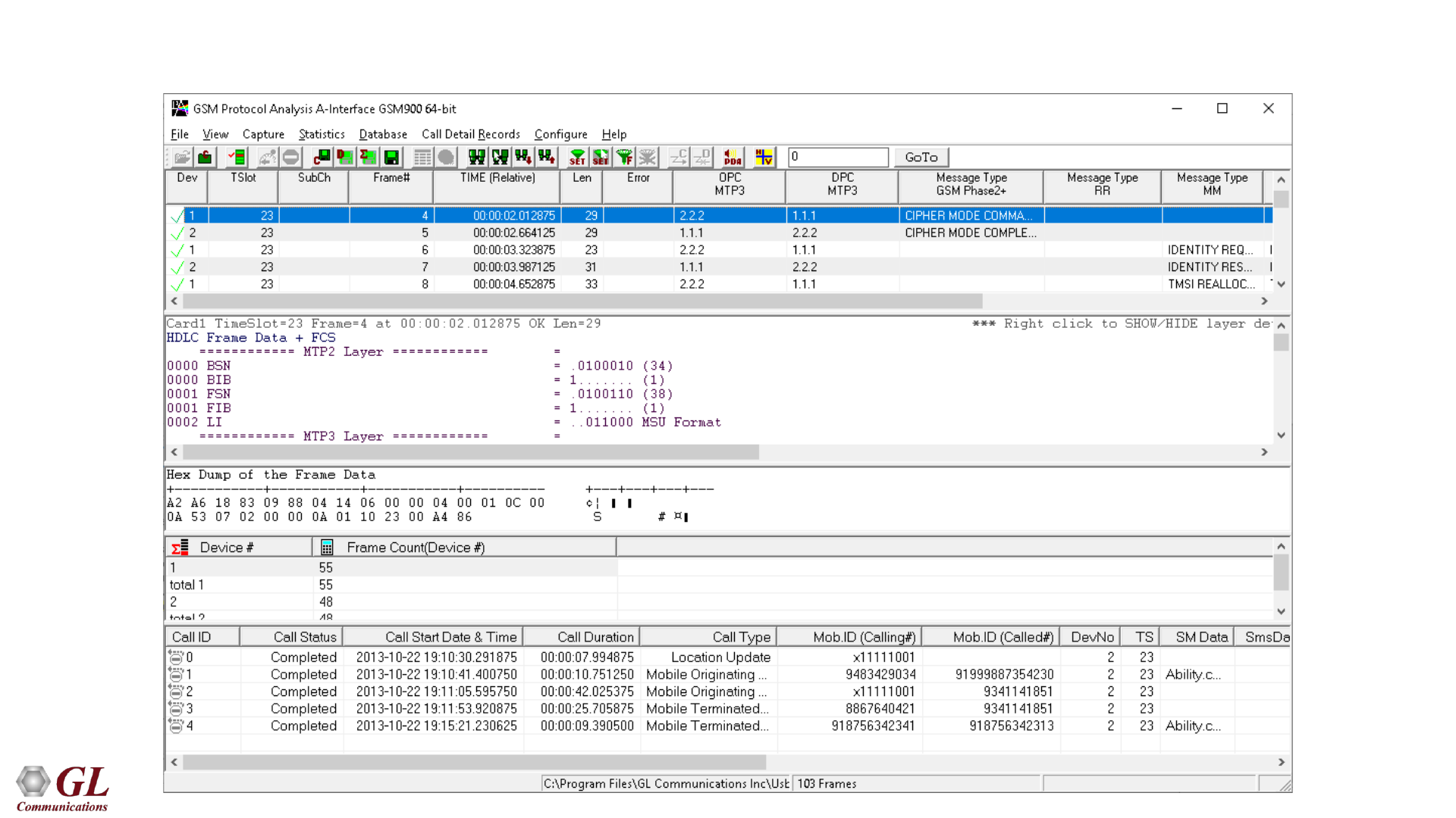
Key Features
• Monitor GSM network real-time, offline, as well as remote
• Multiple streams of GSM traffic on various T1 E1 channels can be simultaneously decoded with different
GUI instances
➢ Displays Summary, Detail, Hex-Dump, Statistics, and Call Detail View
• Any protocol field can be added to the summary view, filtering, and search features providing users more
flexibility to monitor required protocol fields
• Option to create multiple aggregate column groups and prioritize the groups as per the requirement to
display the summary results efficiently
• Allows the user to create search/filter criteria automatically from the current screen selection
• Captured frames can later be used for traffic simulation
• Remote monitoring capability using GL's Network Surveillance System
28
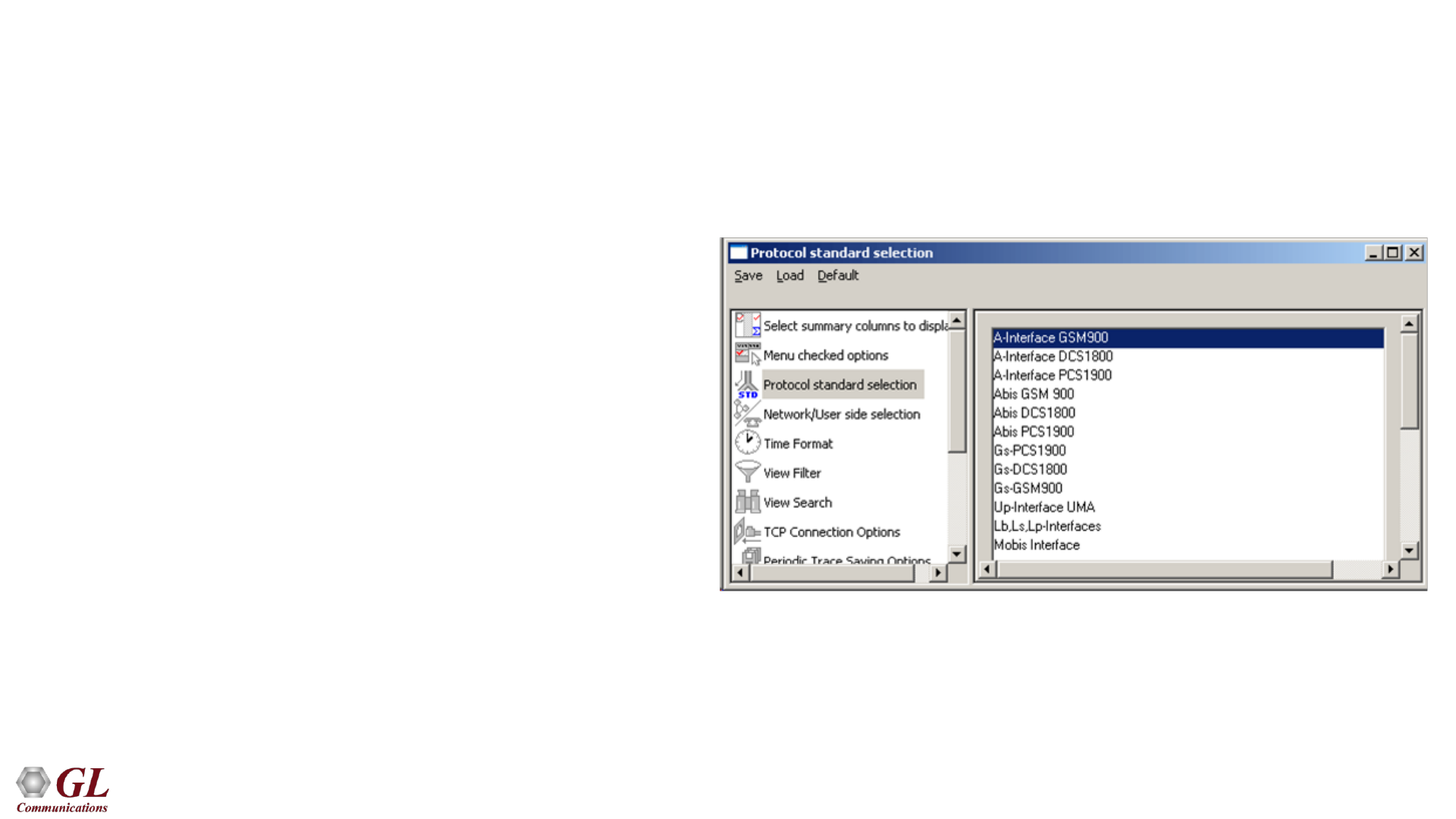
Protocol Standards
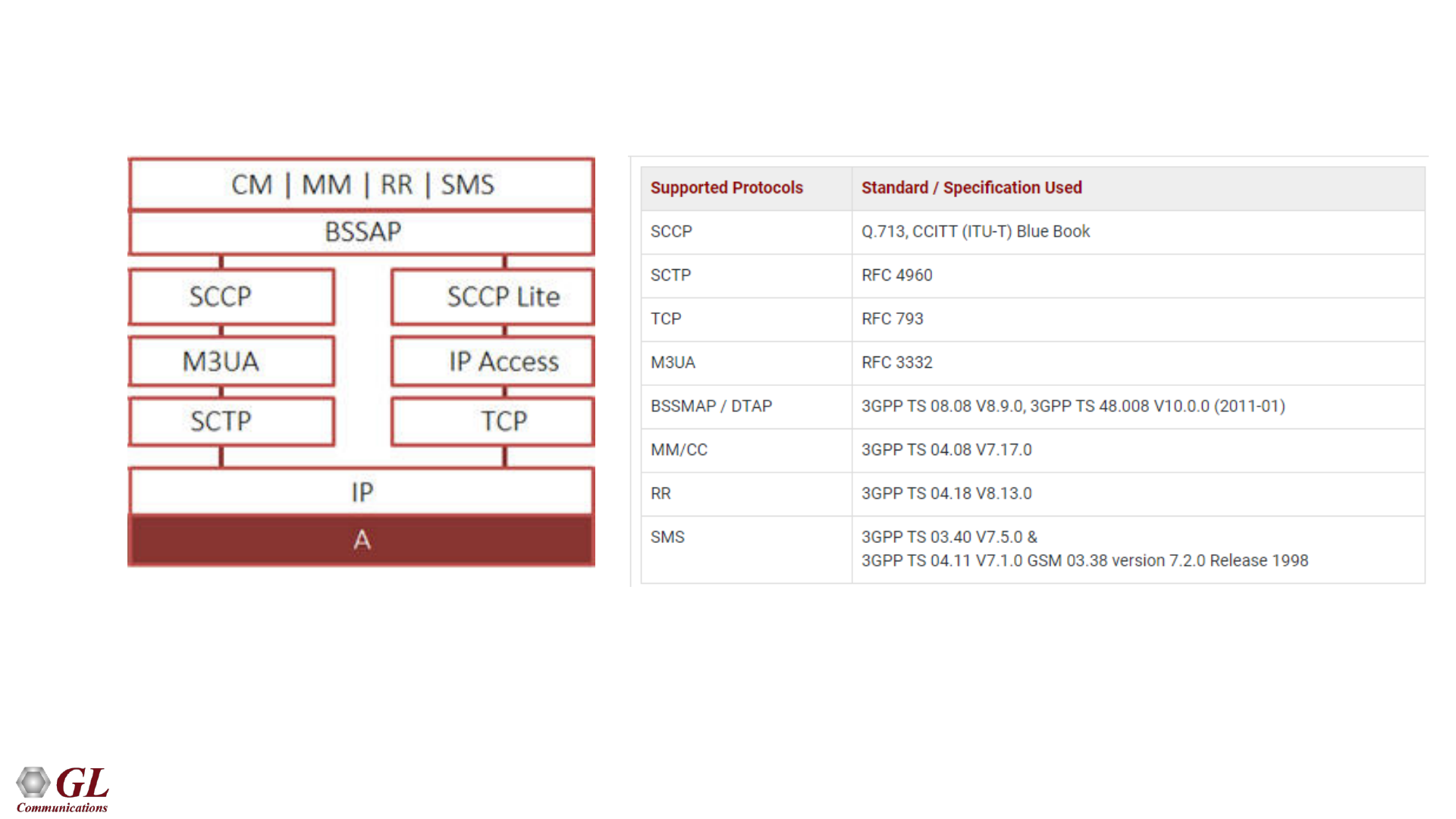
• A Interface - MTP2, MTP3, SCCP, BSSMAP,
SMS, MM, & CC
• Abis Interface – LAPD, BTSM, RR, SMS, MM &
CC
• Gs Interface – MTP2, MTP3, BSSAP+
• Lb, Ls, Lp Interface – RRLP, BSSLAP.
SMLCPP, LLP, BSSAP-LE, SCCP, MTP3, &
MTP2
• UP Interface - UMA Protocols , TCP, UDP, IP,
&MAC
• Motorola Proprietary Mobis Interface
29
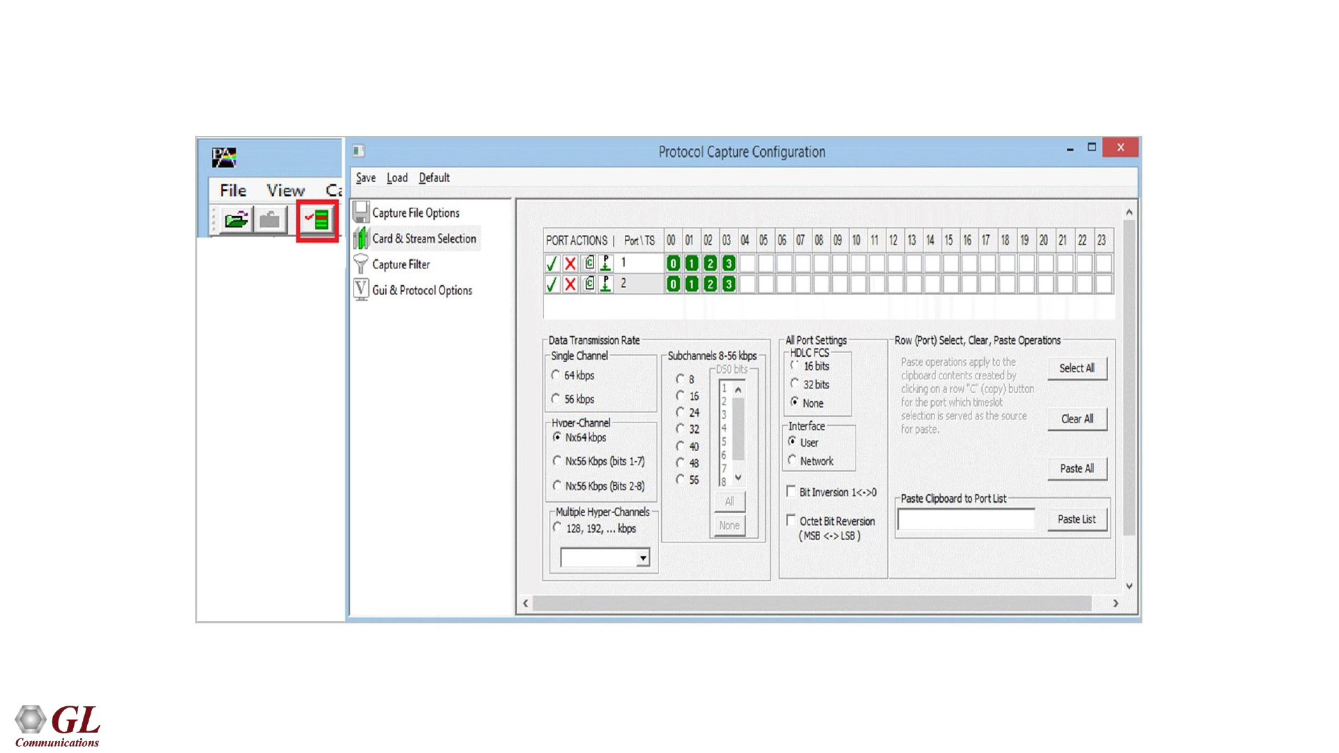
Real-time Capture
30
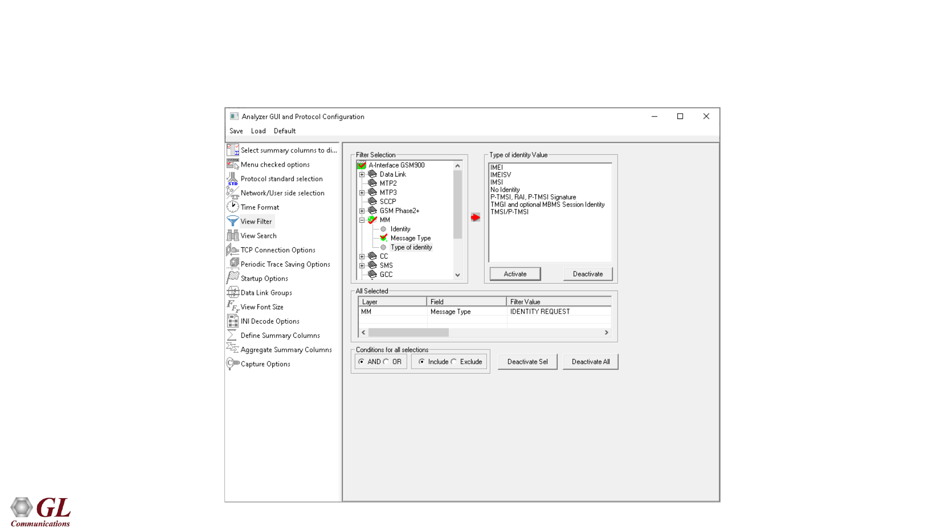
Filtering Criteria
• Search and Filter features provide very fast search/filter for finding the required frames
31
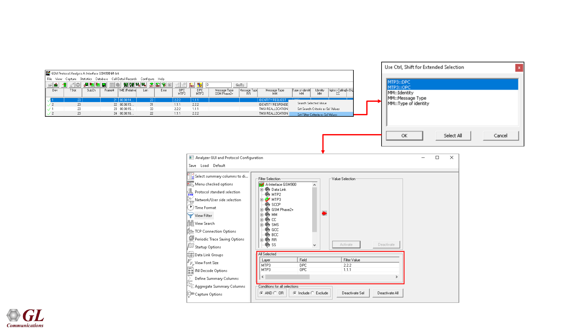
Filtering Criteria From Screen Selection
• Allows the user to create filter criteria automatically from the current screen selection
32
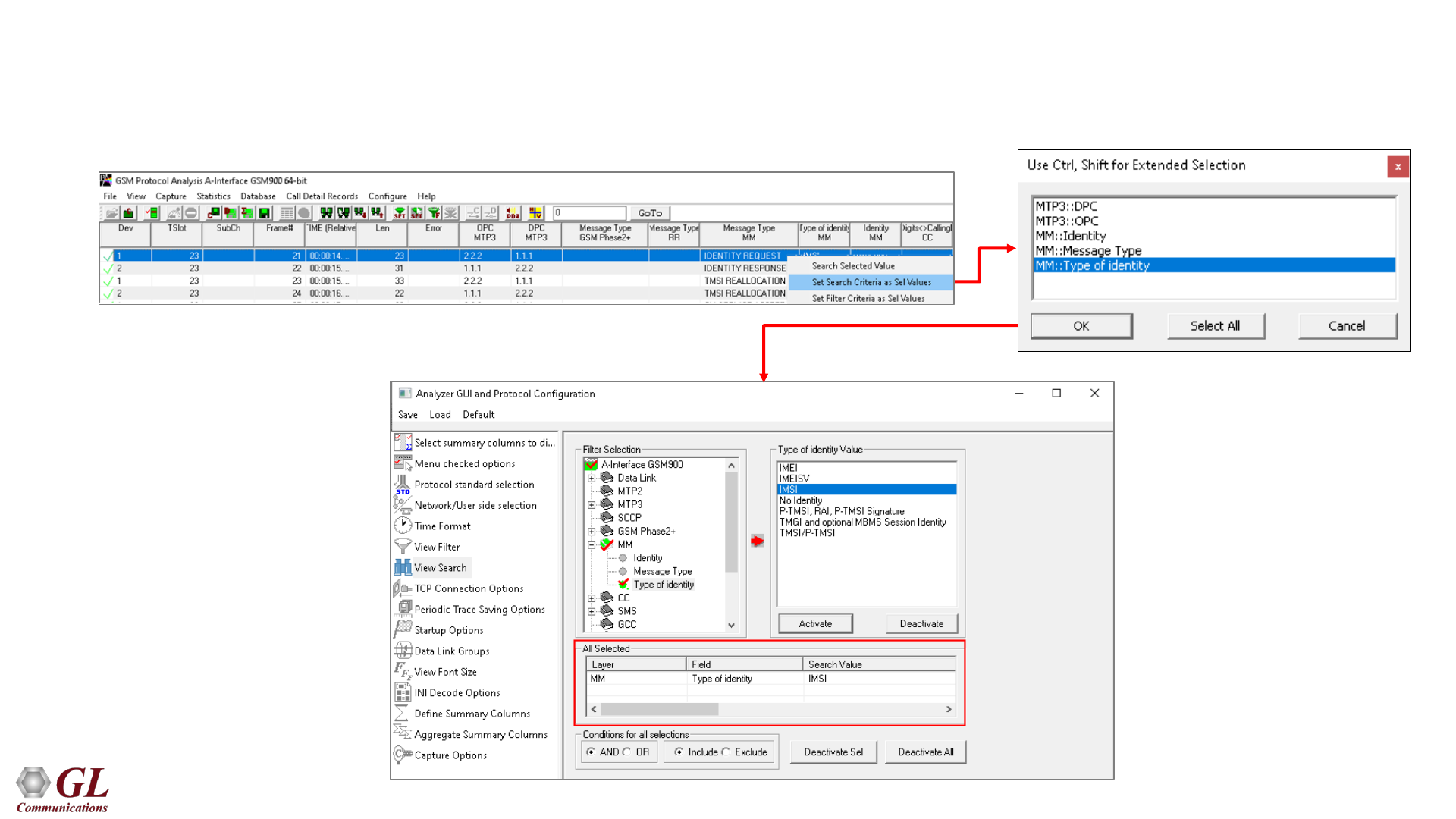
Search Criteria From Screen Selection
• Allows the user to create search criteria automatically from the current screen selection
33
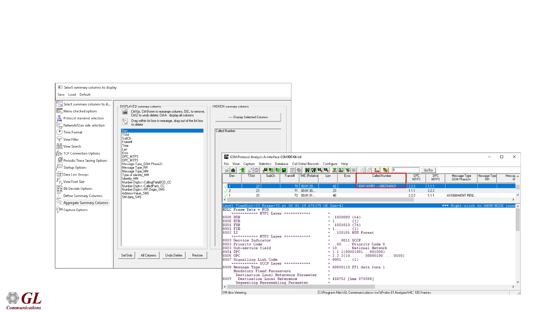
Define Summary Columns
• Required protocol fields can be added through Define summary column option
• User can remove the protocol field which is not required
34
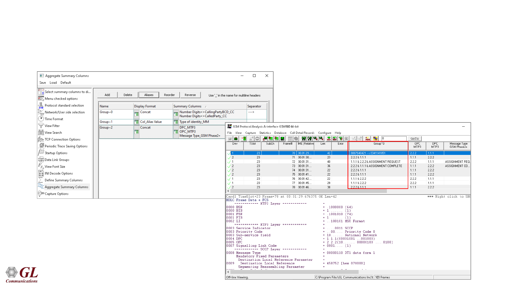
Aggregate Group Column
• The user can create multiple aggregate column groups and prioritize the groups as per the requirement to display
the summary results efficiently
Selection of Summary Column
Output display in analyzer
35
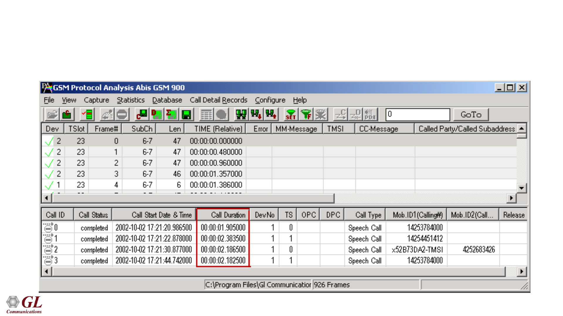
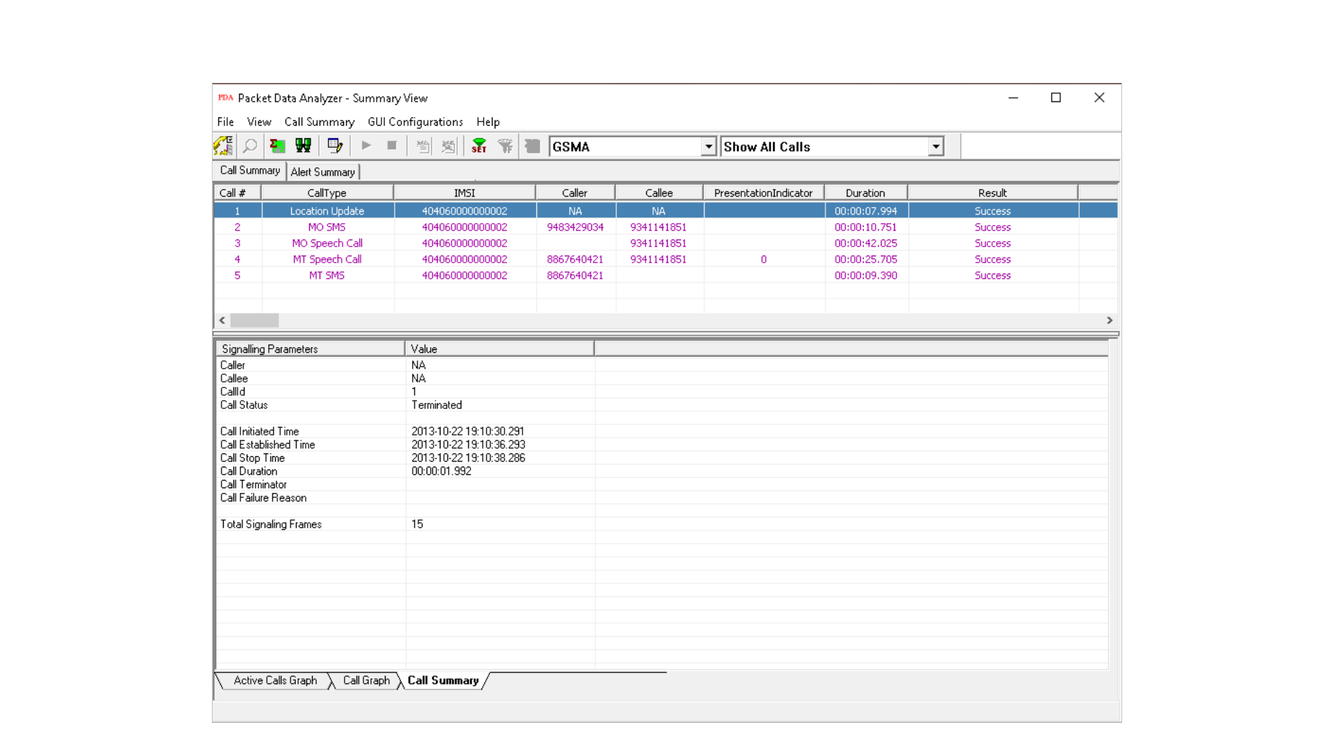
Call Detail Records
• Call trace defining important call specific parameters such as call ID, status (active or completed),
duration, CRV, release complete cause etc. are displayed

36
Applications
• Used as independent standalone units as "probes" integrated in a network surveillance systems
• Triggering, collecting, and filtering for unique subscriber information and relaying such information to a
back end processor
• Collecting Call Detail Records (CDR) information for billing

37
MAPS GSM A Emulator
(Testing over T1 E1)
38
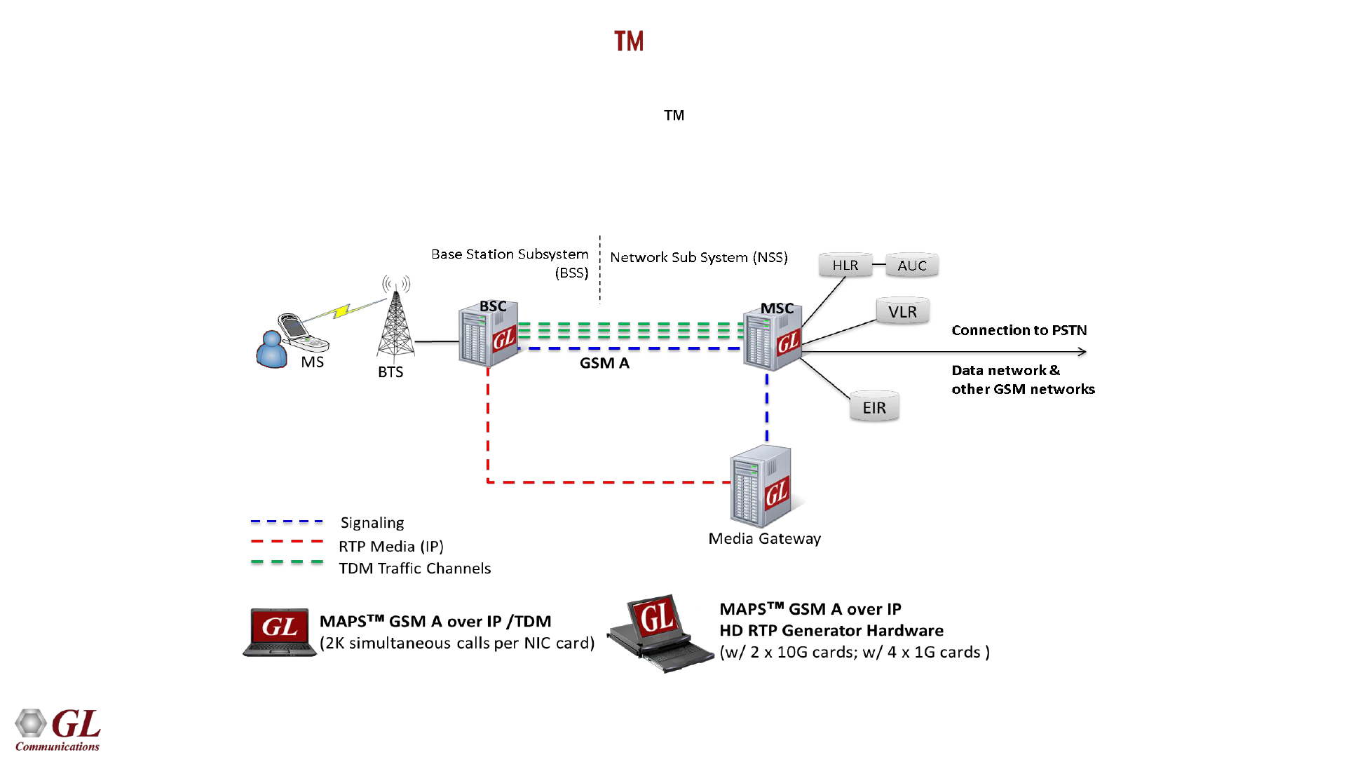
MAPS - GSM A Emulator (XX692)
• Scripted GSM A Interface simulation over TDM (T1 E1) using GL’s MAPS
• Simulates BSC and MSC entities
39
Supported Protocol Standards
40
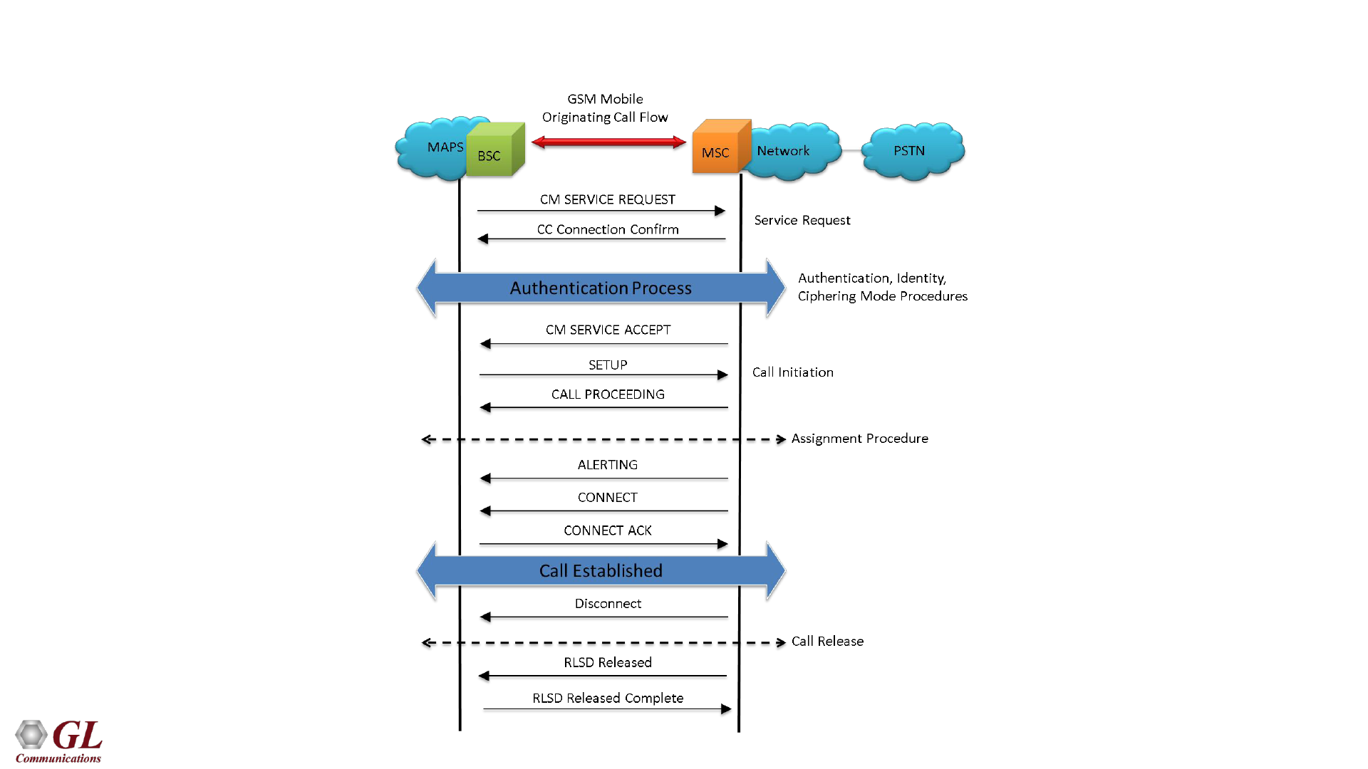
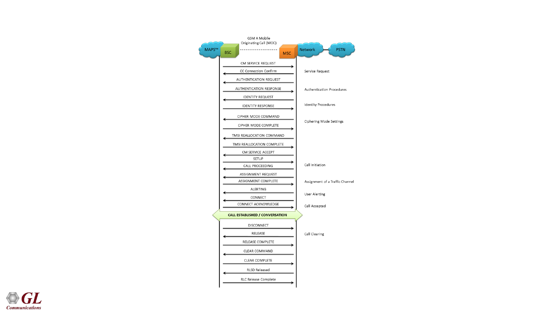
GSM A Mobile Originating Call Flow
41
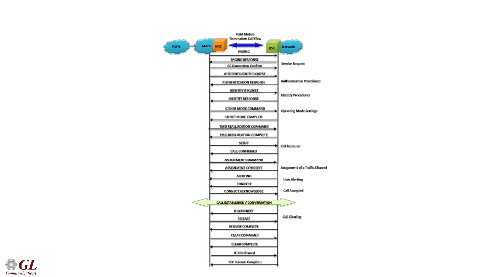
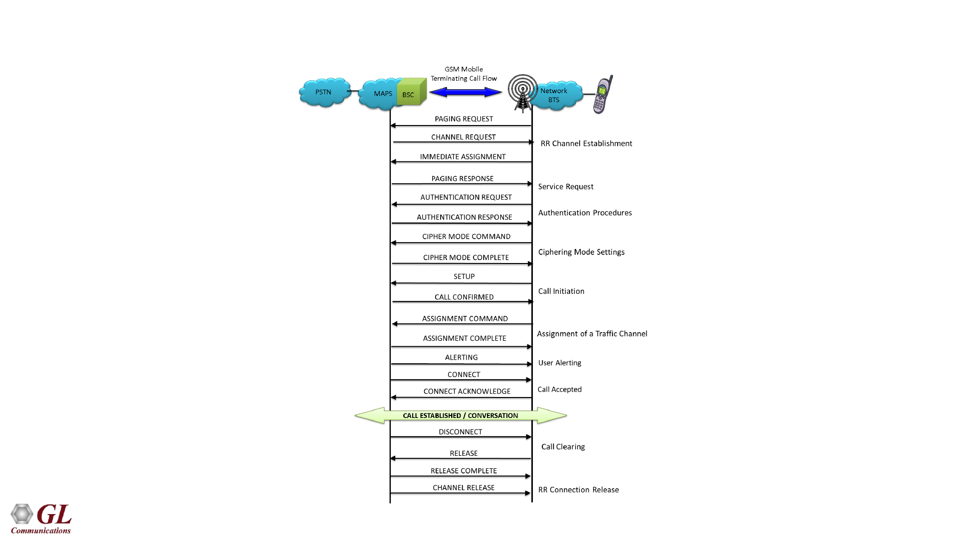
GSM A Mobile Terminating Call Flow
42
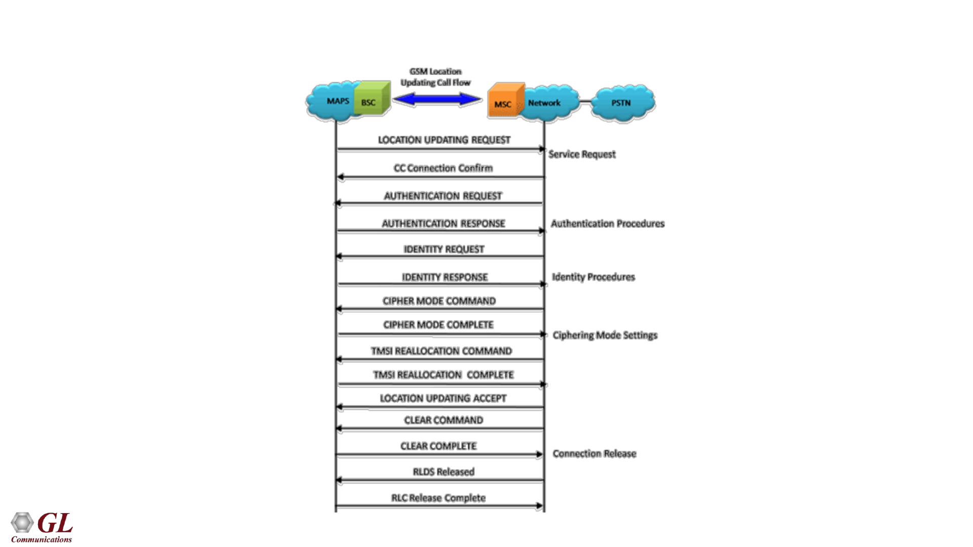
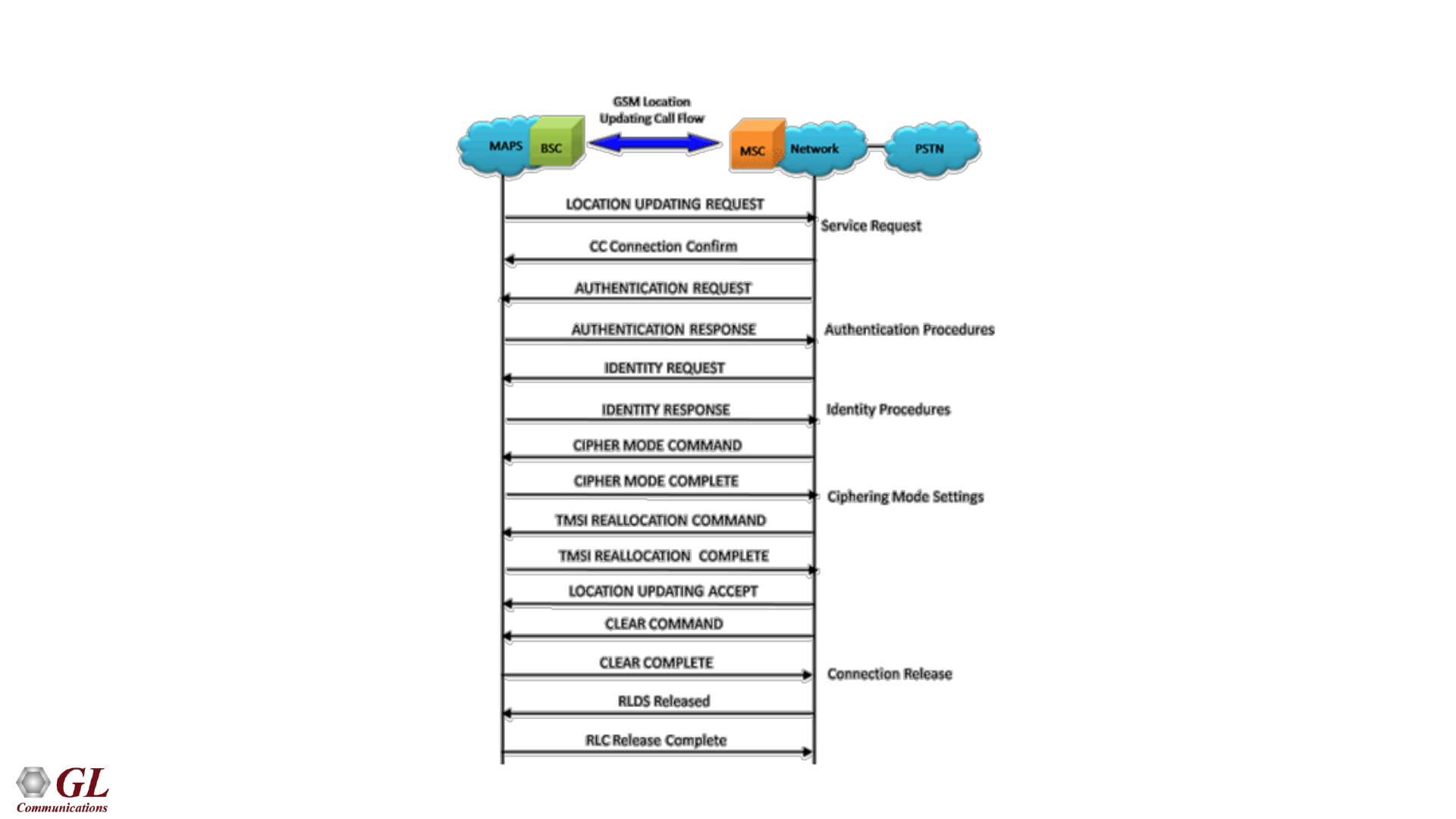
Location Updating Call Flow
43
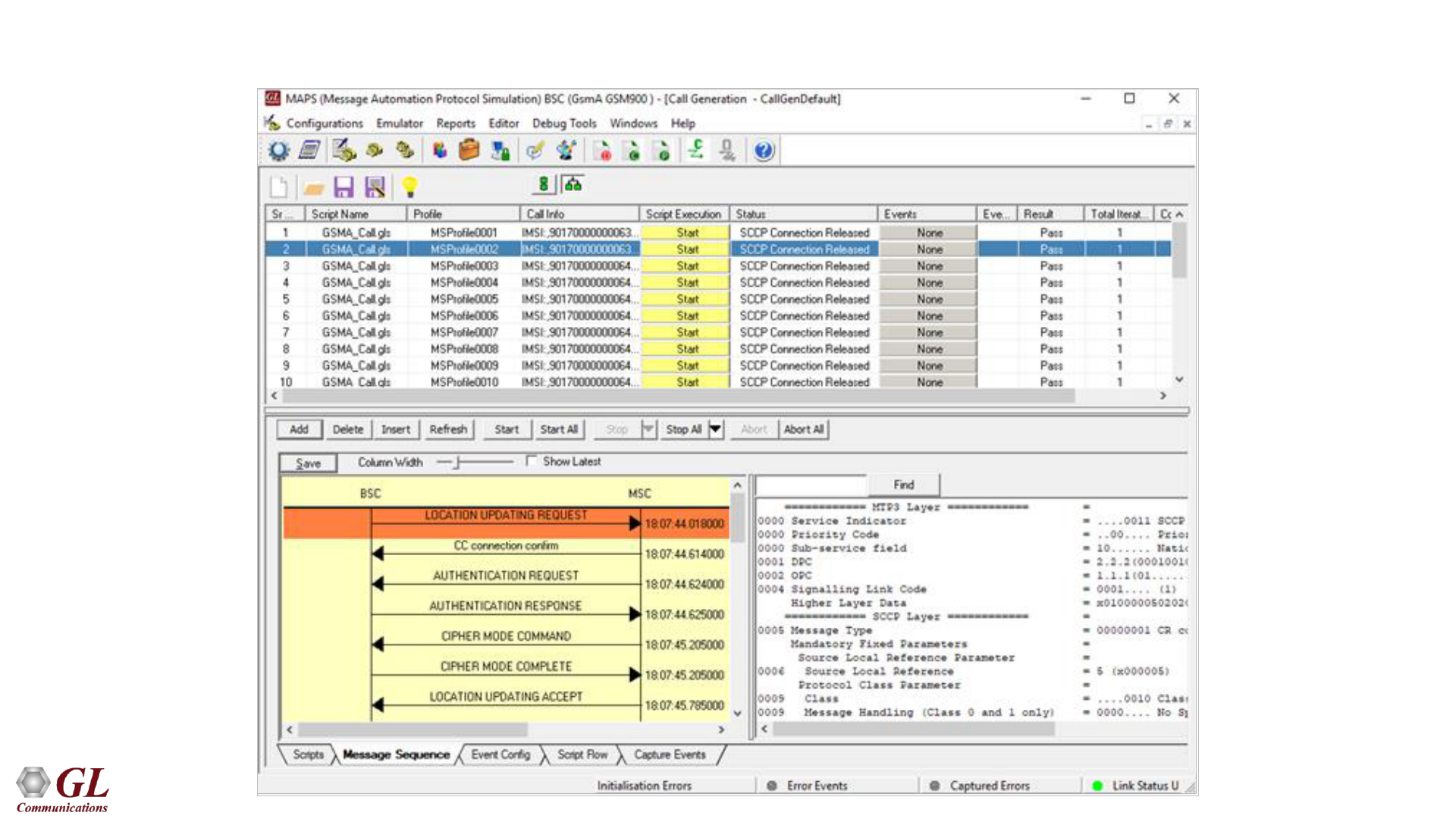
GSM A Call Generation
44
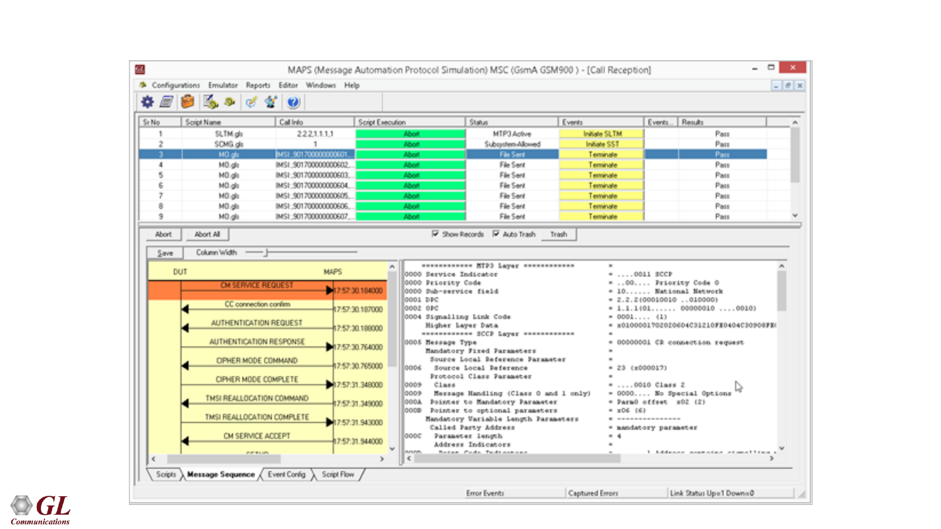
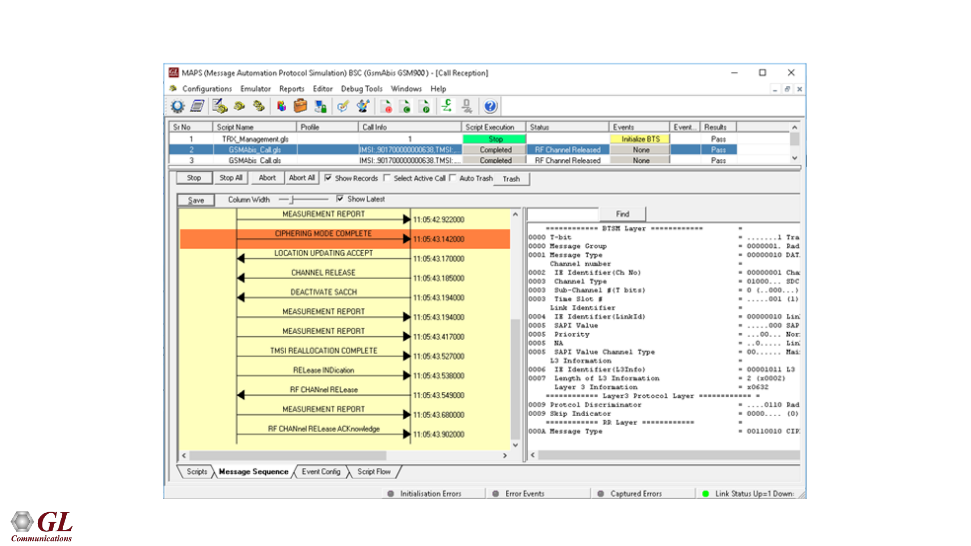
GSM A Call Reception
45
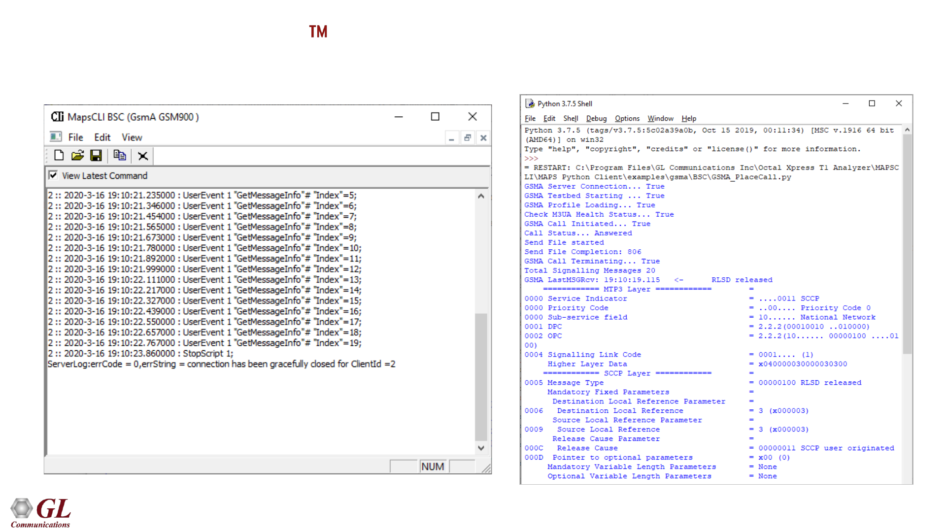
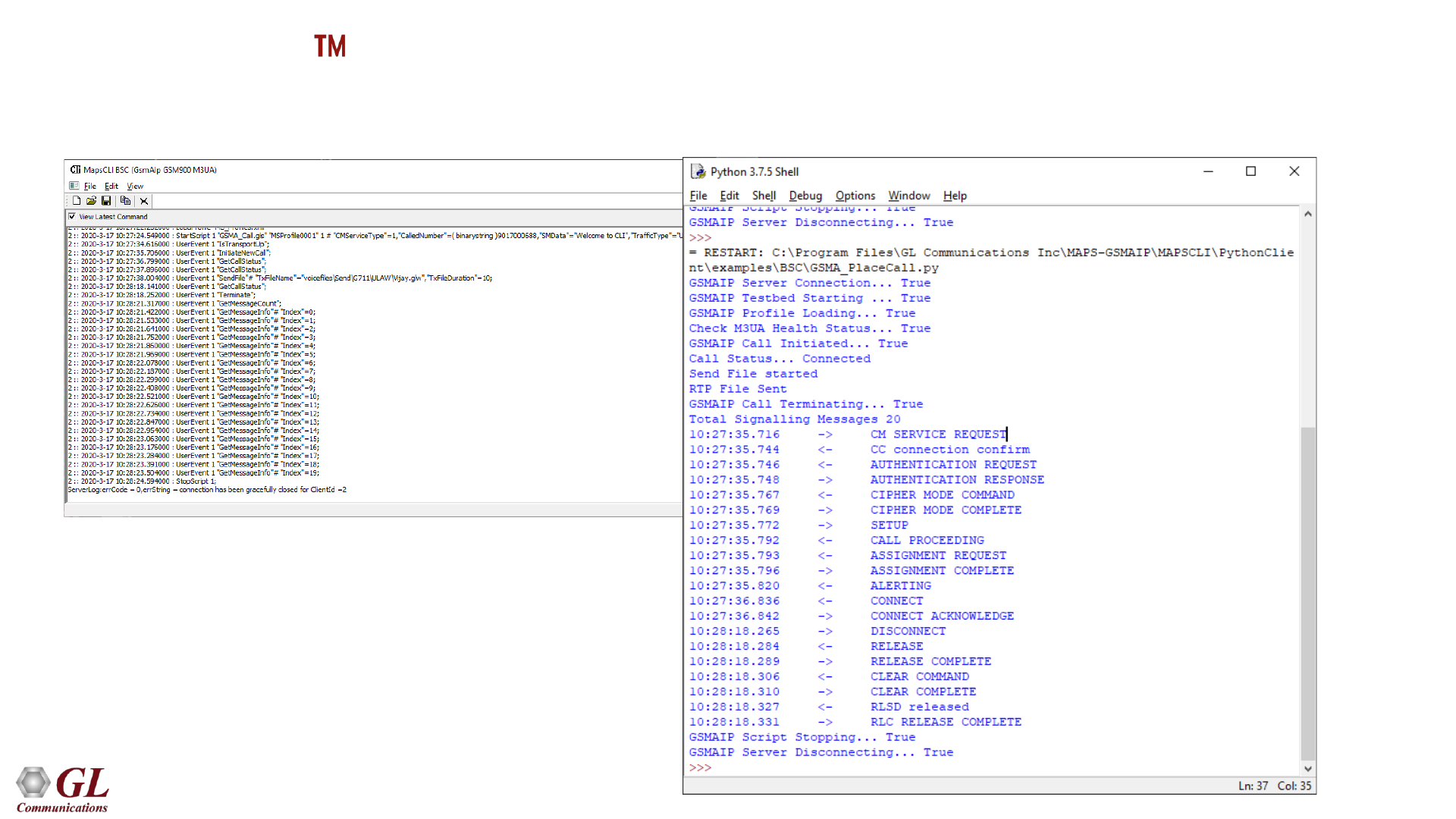
MAPS GSMA Command Line Interface (CLI)
MAPS GSMA CLI Server Sample Python Client Script

46
MAPS GSM Abis Emulator
(Testing over T1 E1)
47
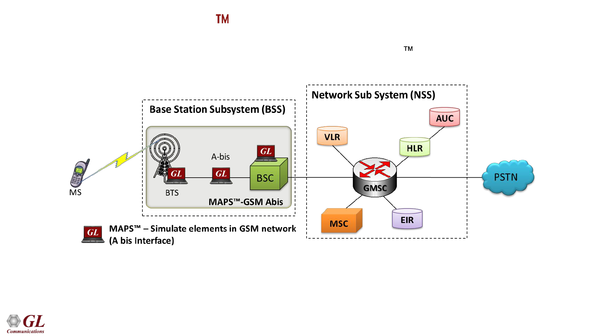
MAPS - GSM Abis in the Network
• Scripted GSM Abis Interface simulation over TDM (T1 E1) using MAPS
• Simulates BSC and BTS entities
48
Supported Protocol Standards
49
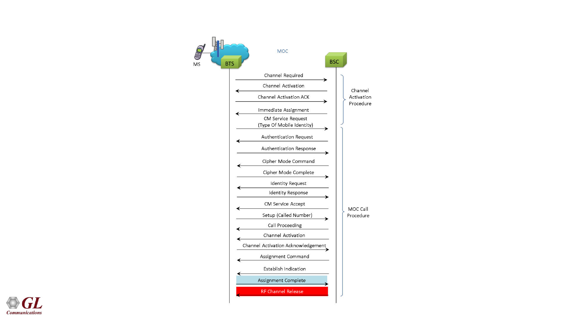
GSM Abis Mobile Originating Call Flow

50
GSM Abis Mobile Terminating Call Flow
51
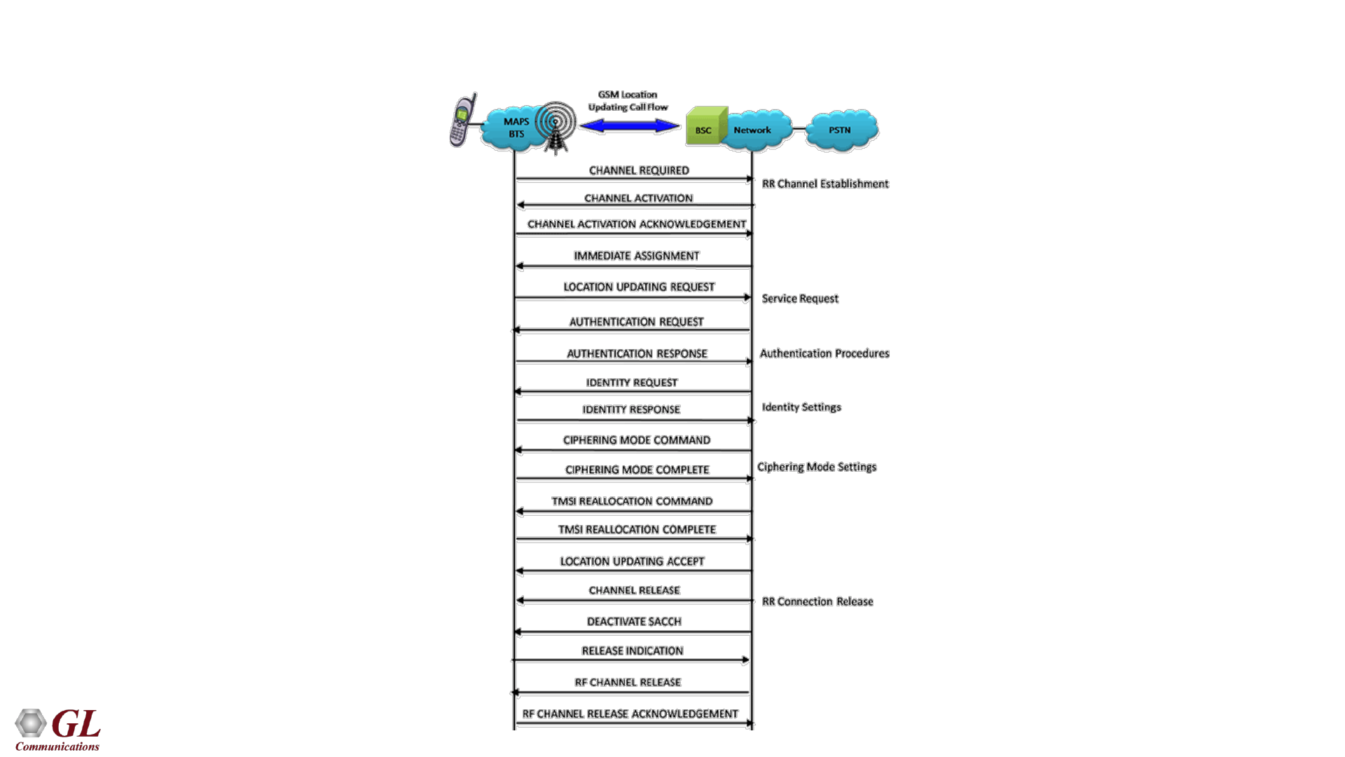
GSM Abis Location Updating Call Flow
52
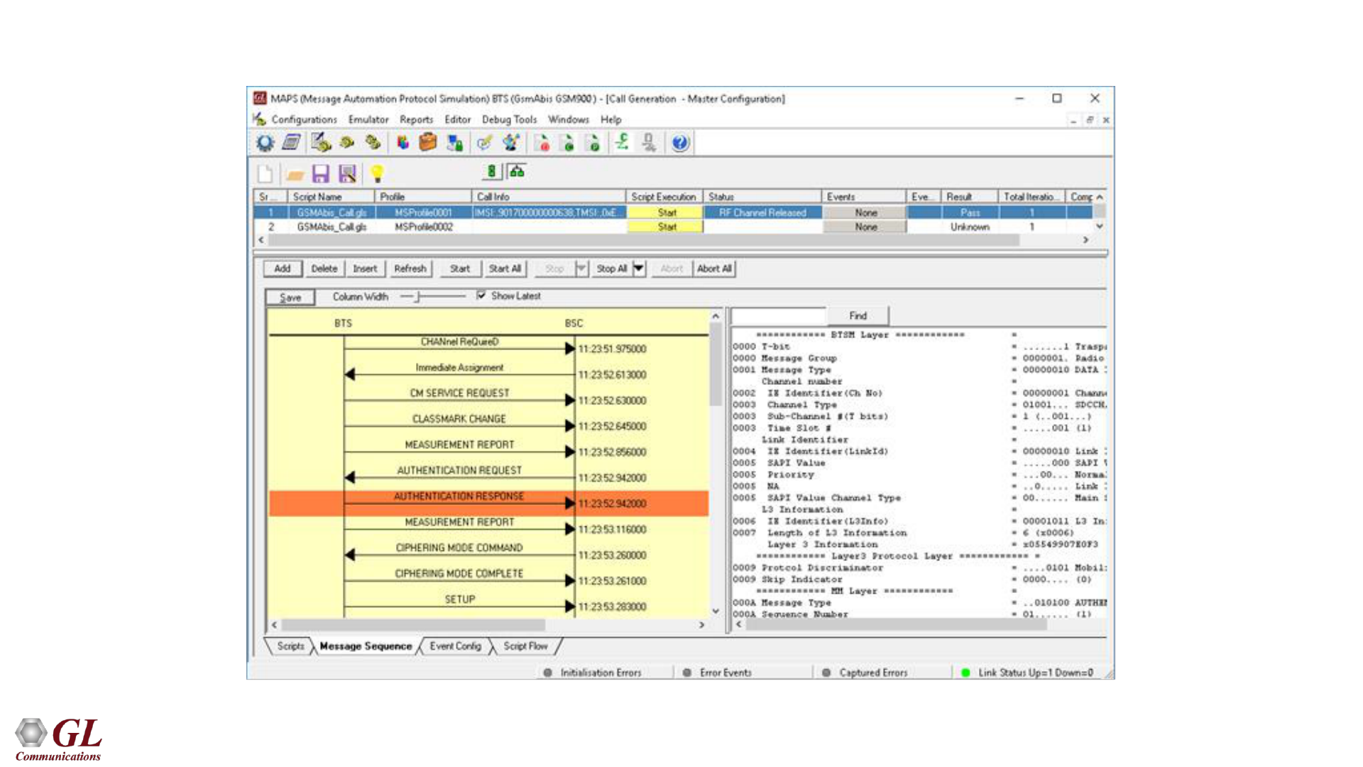
GSM Abis Call Generation
53
GSM Abis Call Reception

54
MAPS - GSMAoIP (GSM A over IP)
(PKS137)
55
MAPS - GSMAoIP
• Scripted GSM A simulation over IP using MAPS
• Simulates BSC or MSC entities
• User-friendly GUI for configuring the SCTP Layer parameters
56
GSMAoIP Mobile Originating Call Flow
57
GSMAoIP Mobile Terminating Call Flow
58
GSMAoIP Location Updating Call Flow
59
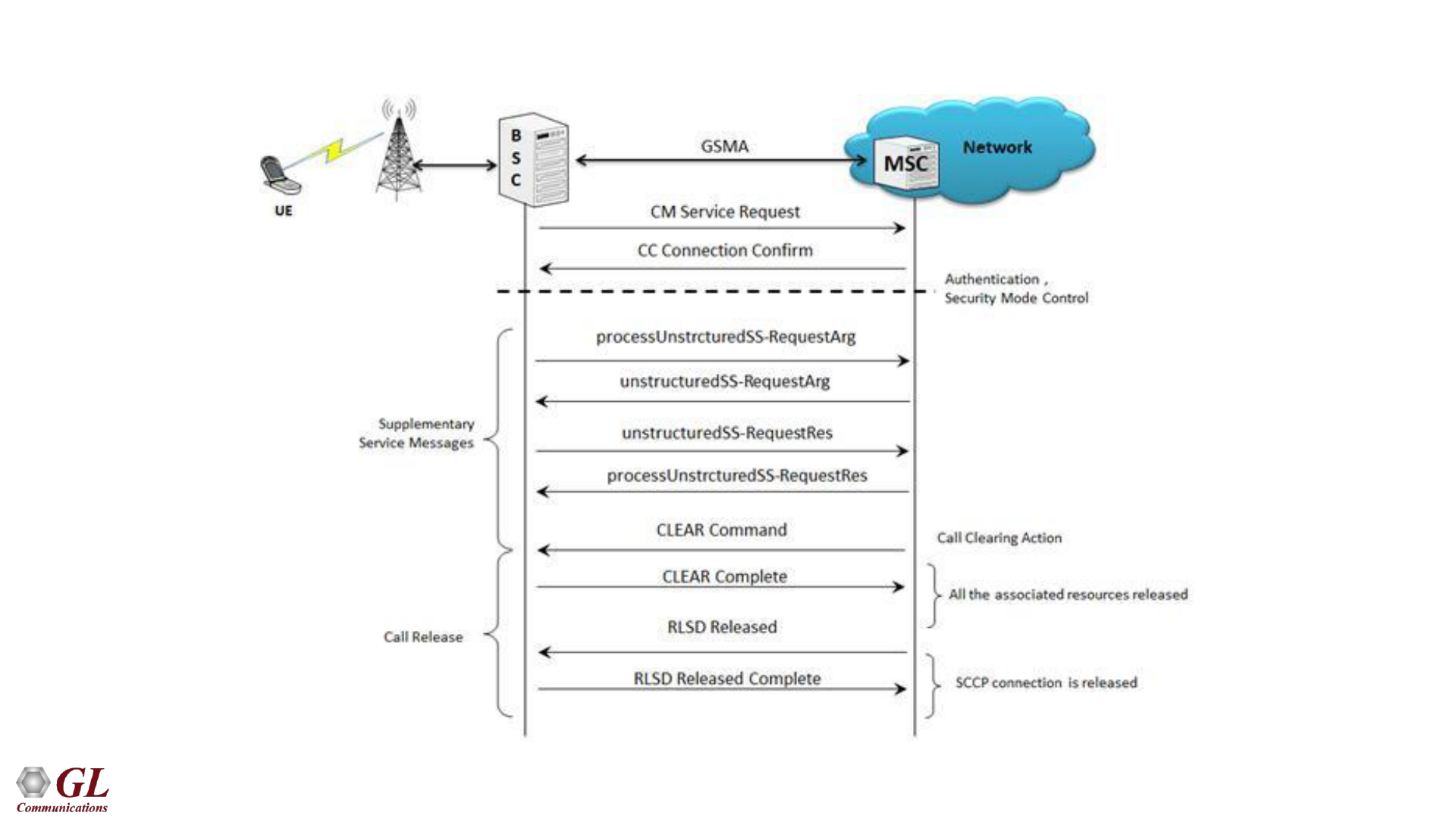
GSMAoIP Supplementary Service Activation Call Flow
60
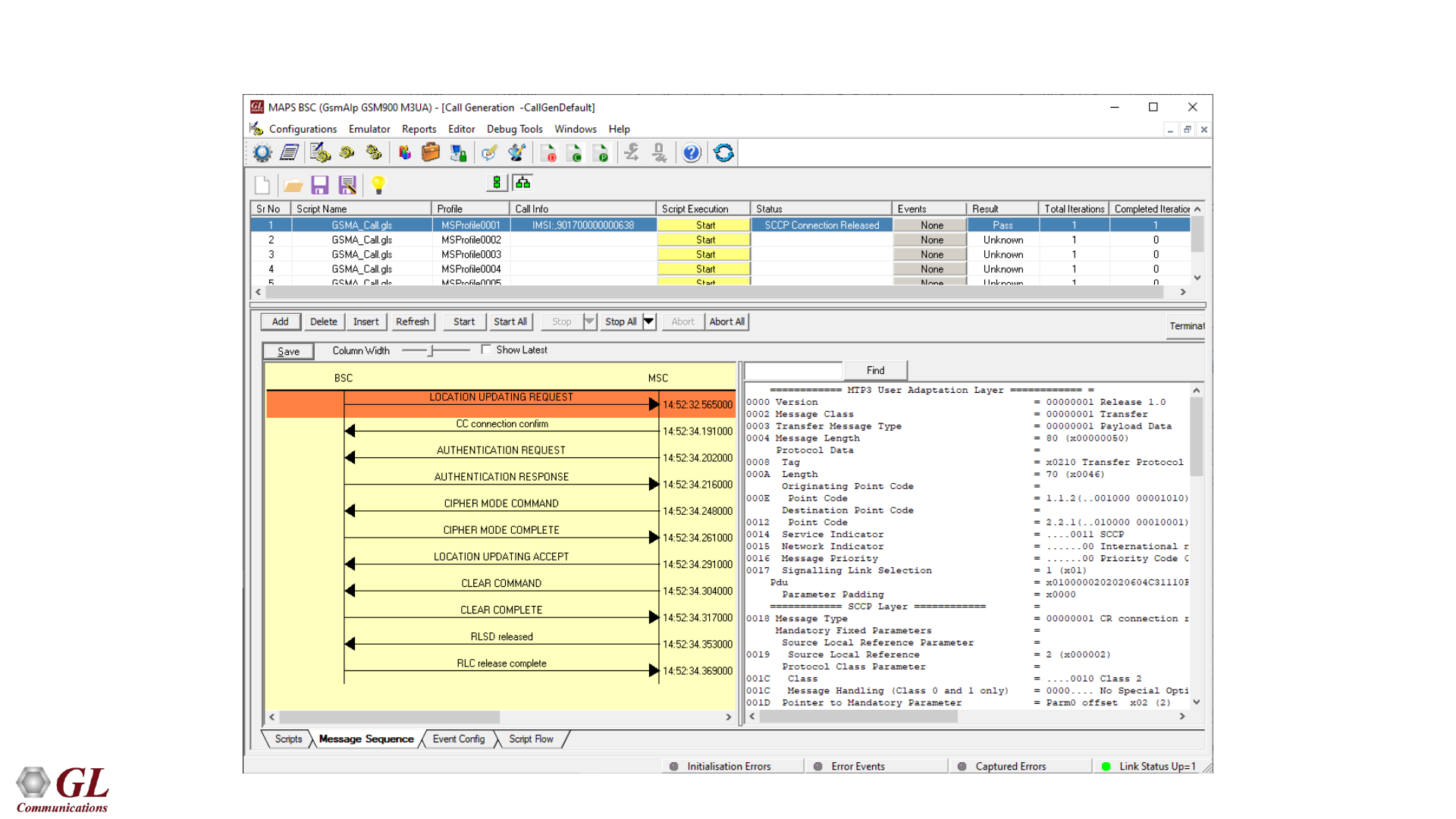
GSMoIP Call Generation
61
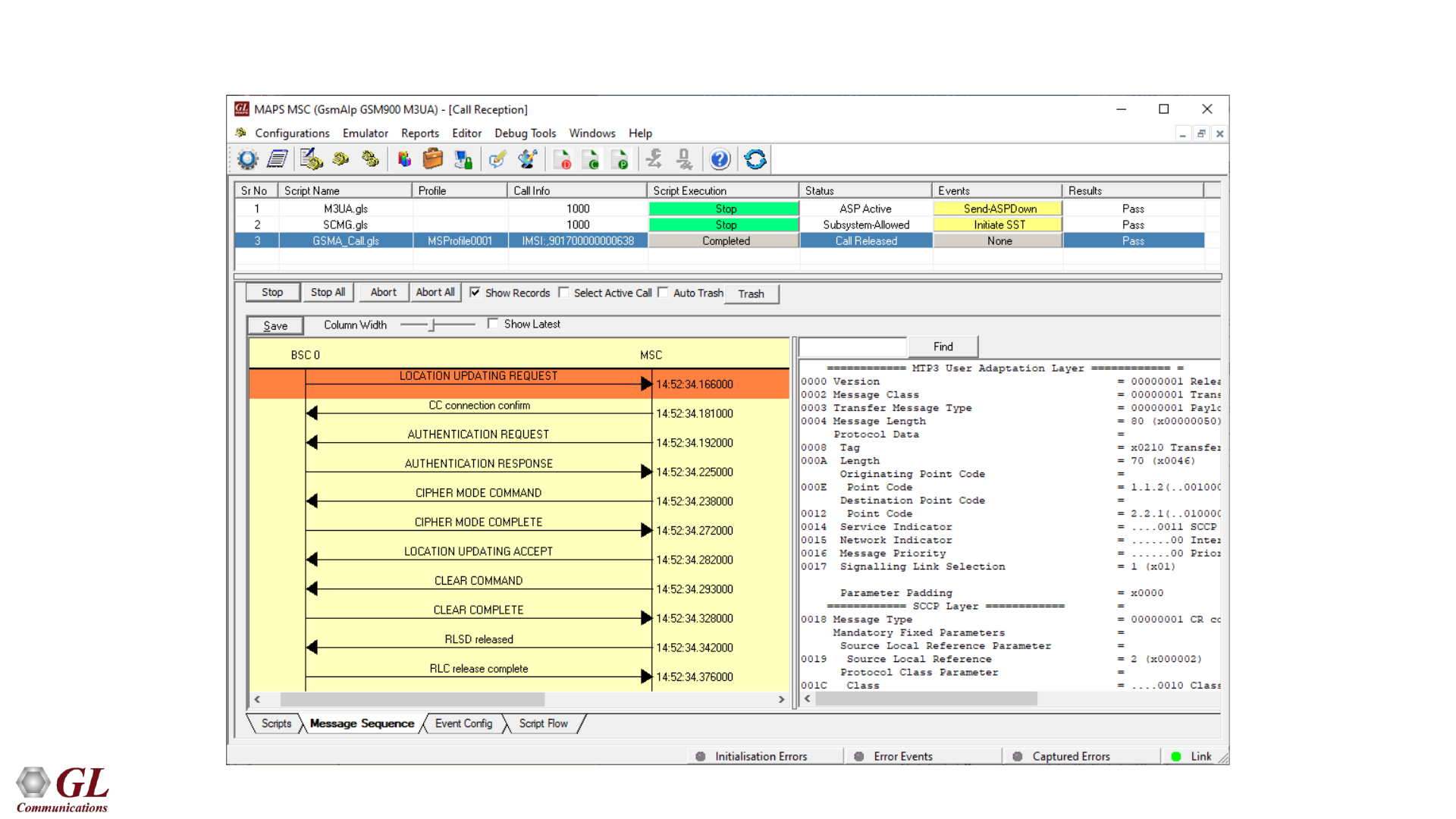
GSMoIP Call Reception
62
MAPS GSMA over IP Command Reference Interface (CLI)
MAPS GSMAIP CLI Server
Sample Python Client Script

63
GSM Packet Data Analysis (PDA)
64
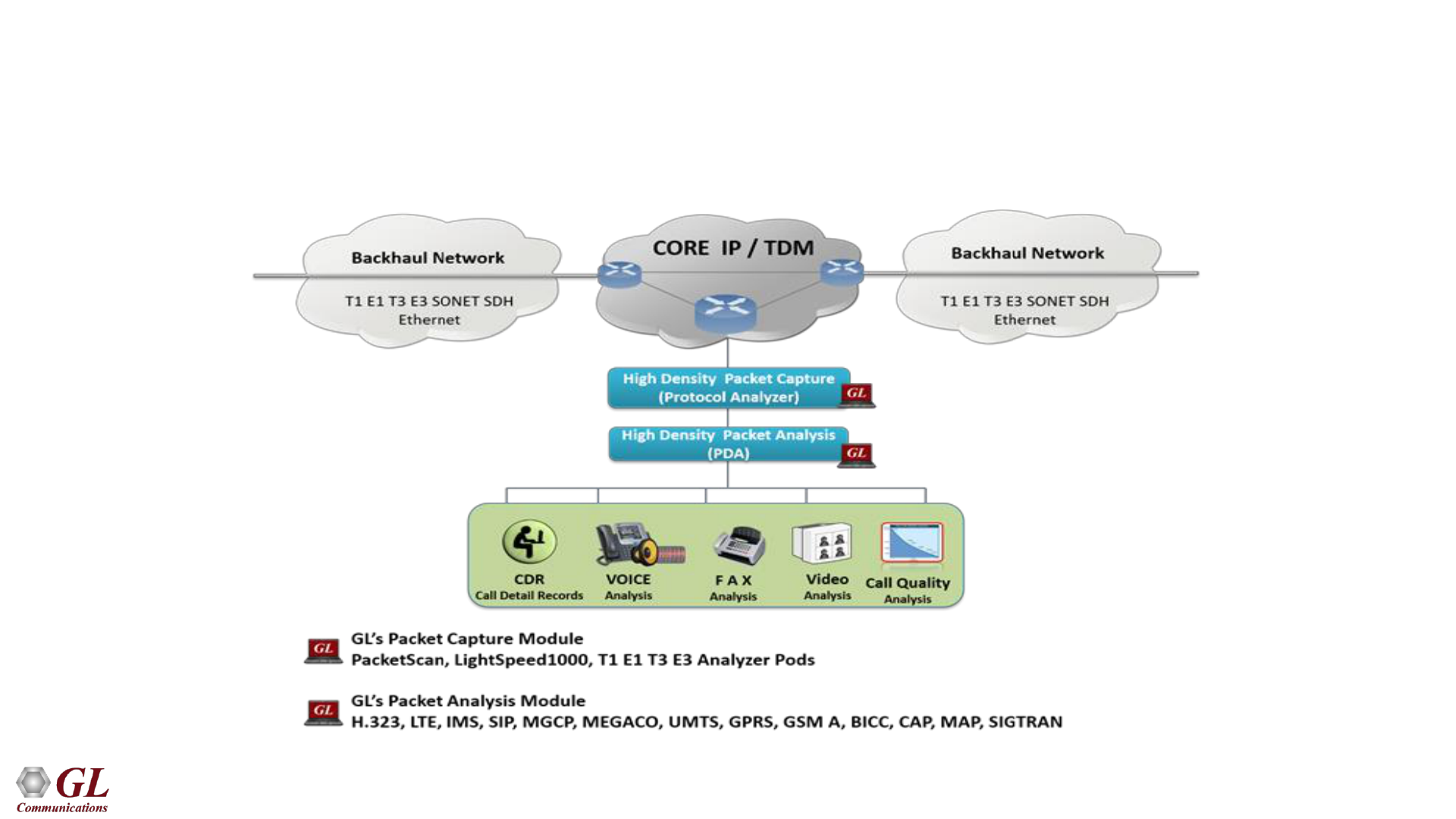
Packet Data Analyzer over TDM
• Monitors live TDM networks including capture, analysis, and reporting of every call-in detail. Supported
protocols include CAS, ISDN, ISUP, CAMEL, MAP, INAP, and GSM
65
Main Features
CDR, Call Flow,
Statistics, and Report
Generation
•
Isolates call specific information for each individual call from the captured data and
displays the information in an organized fashion
•
A host of call and message counters gives the user an instantaneous snapshot of the
traffic on the network
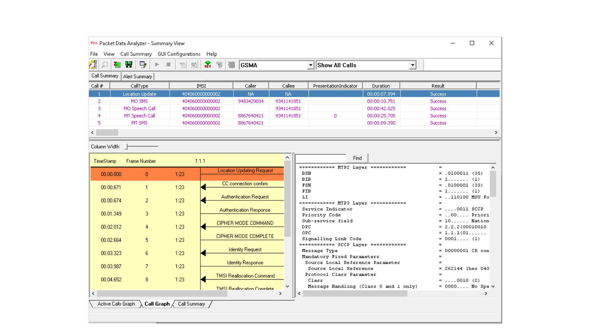
• Pictorial representation of the statistics including ladder diagrams for the calls of various
protocols
•
Ability to export and analyze call detail records of completed calls in CSV file format.
•
These reports can be further fed to DB and accessed using GL’s NetSurveyorWeb
Lite for analysis
•
Isolates calls, a graphical call flow diagram can be created from a call trace
•
Filters on CDR information feature is used to search required calls by using “key” as
CDR parameters
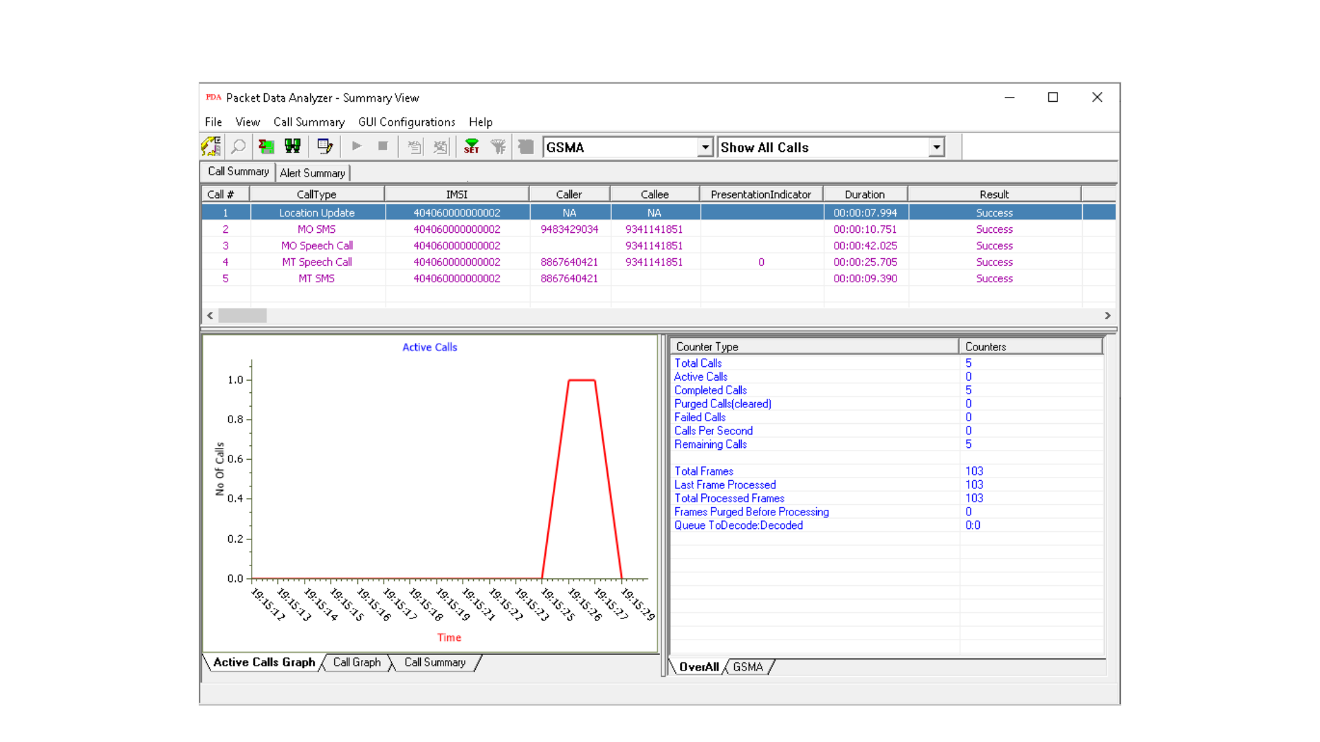
• Event counters on CDR information provides over all count of completed events such as
total calls, active calls, completed calls, purged calls, failed calls, calls per second,
remaining calls and more
•
Flexible options are provided to interchange/hide the columns as required
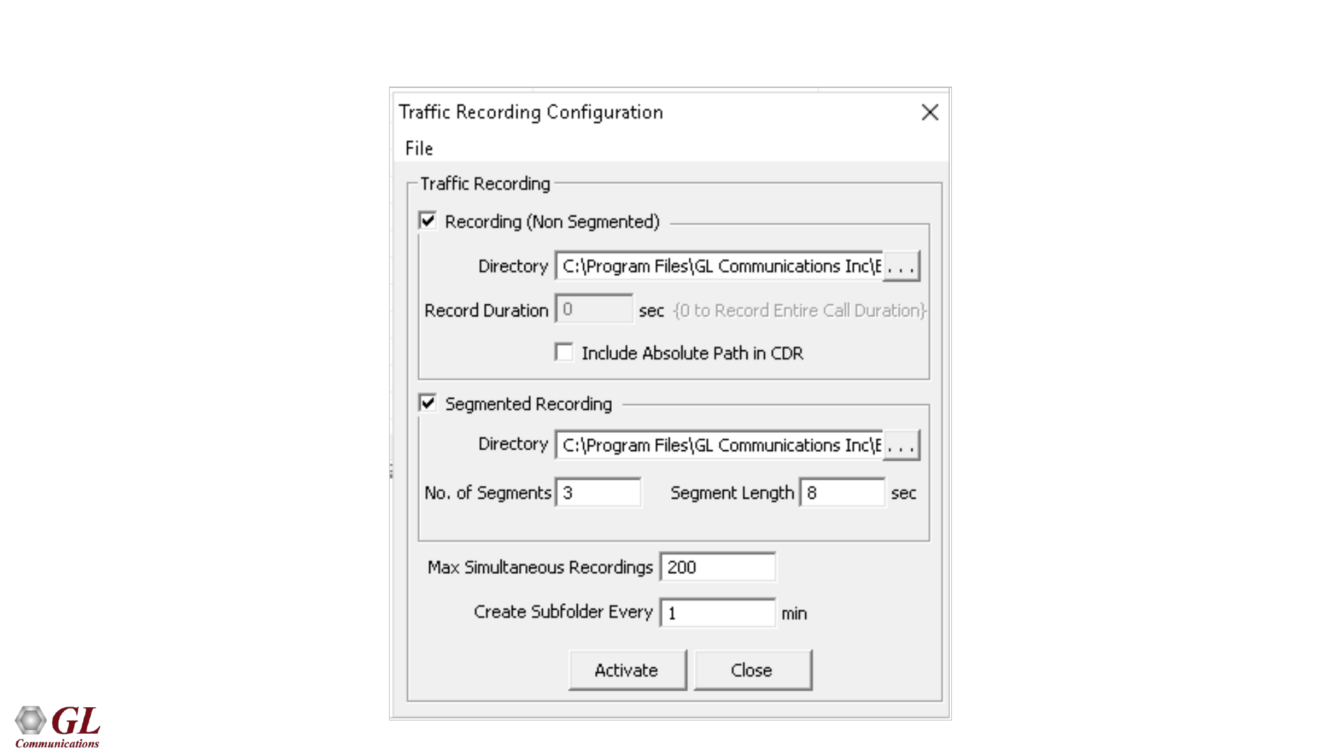
Traffic Recording
•
Supports capturing of voice, digits, tones and FAX etc. to *.PCM file format
Triggers and Actions
• Filter captures based on protocol parameters such as OPC, DPC or CIC in case of ISUP
followed by a set of actions such as save call, send mail, trigger alarm notification etc.
for the completed calls
Exporting Calls
•
Supports saving the selected calls from traffic analyzer into *.HDL, *.PCAP, or
*.PCAPNG formats
66
Data Link Group
67
Traffic Recording Configurations

68
GSMA Call Summary
69
Active Call Graph
70
Summary View
71
Call Summary - Signaling Parameters

72
Triggers and Action Settings
73
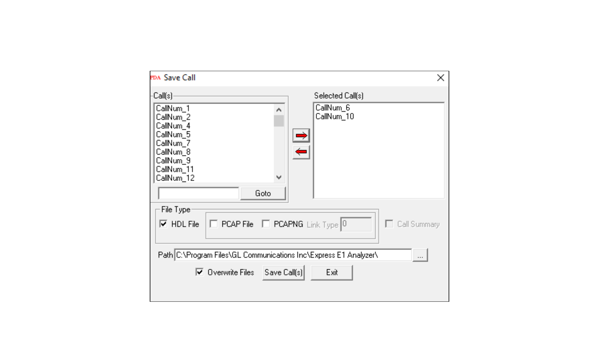
Save Call to File
• Allows the users to save the filtered files either in *.HDL, *.PCAP, or *.PCAPNG format
74
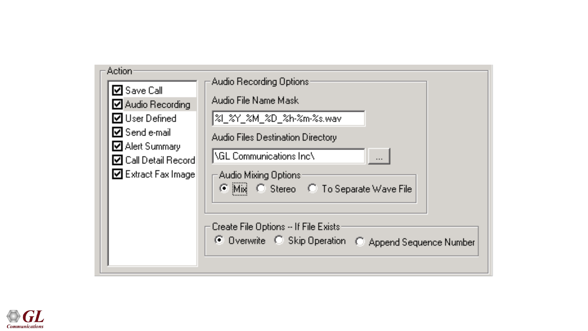
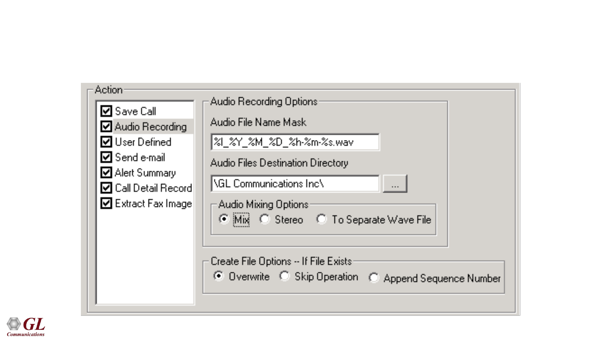
Audio Recording
• Allows to save the filtered files as the voice files in *.wav format
75
Send e-mail
• With this option, the Packet Data Analyzer sends an e-mail containing useful information about each
filtered call
76
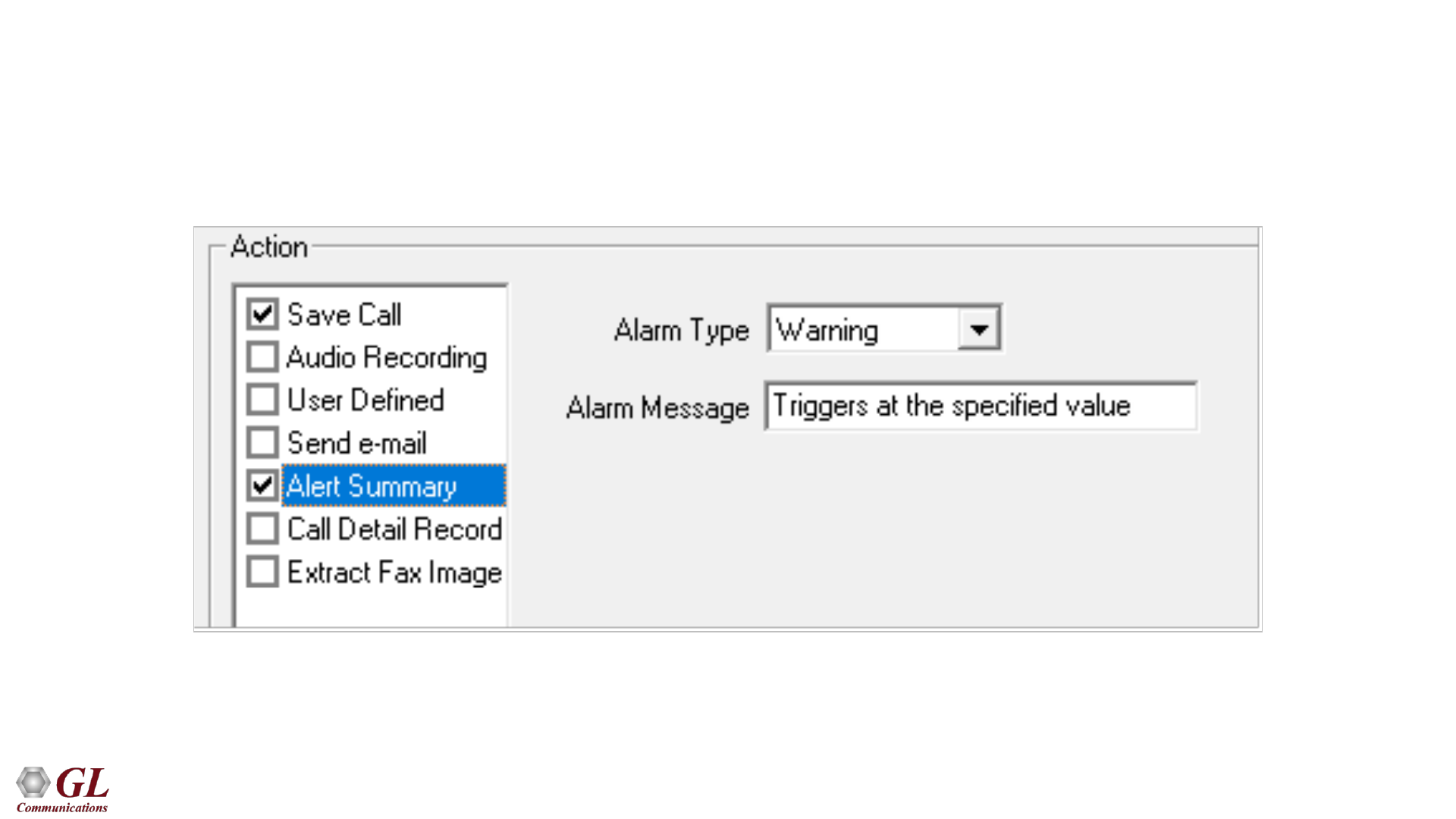
Alert Summary
• This option allows the user to set the alarm type and alarm message for the selected triggering type
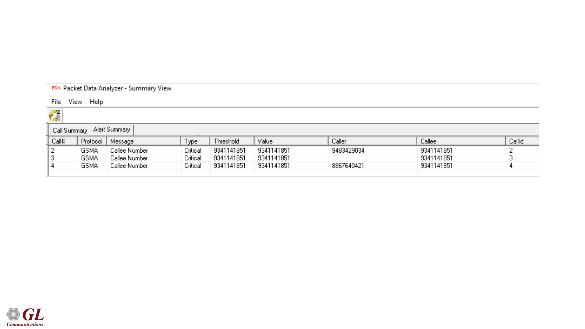
77
Alert Summary
78
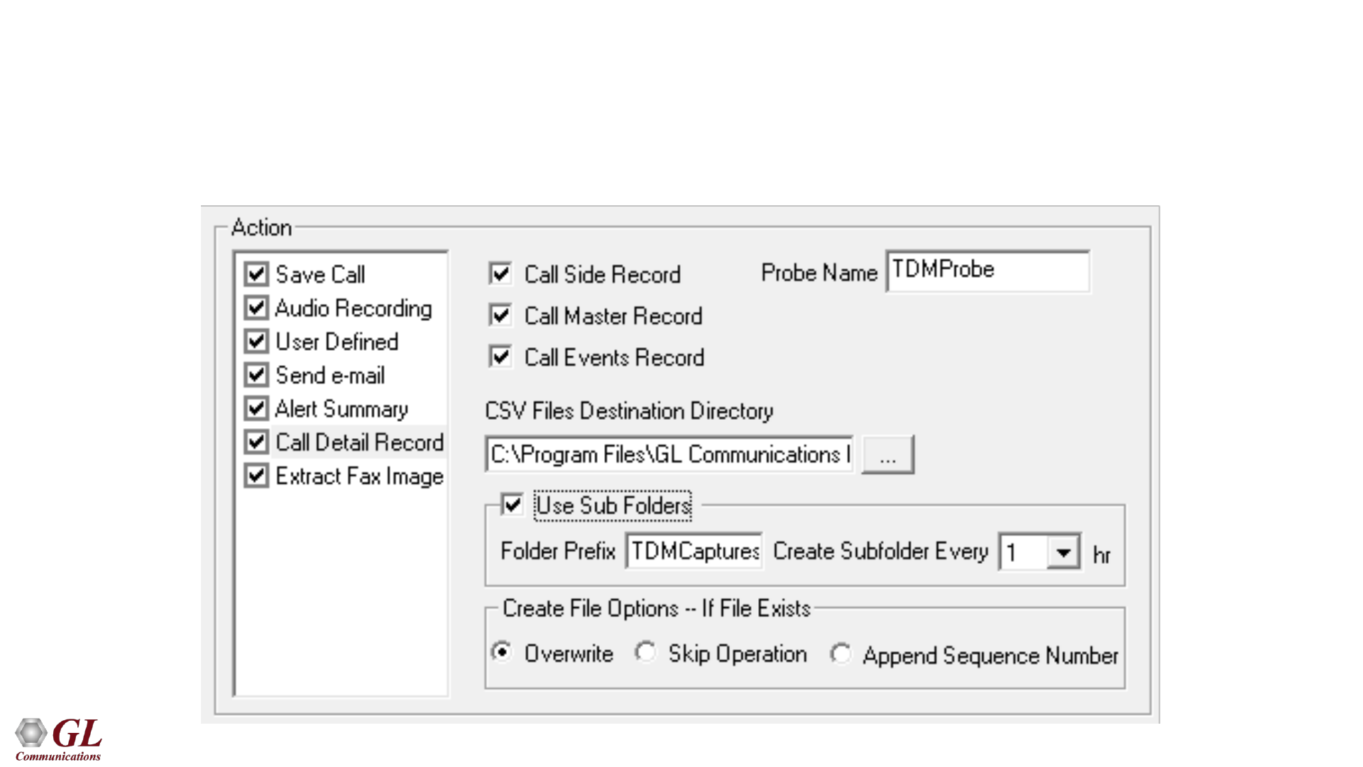
Call Detail Record (CDR)
• With this option, the Packet Data Analyzer can output call detail records (CDR) in the form of three Comma Separated
Value (CSV) files such as Call Side Record, Call Master Record, and Call Events
79
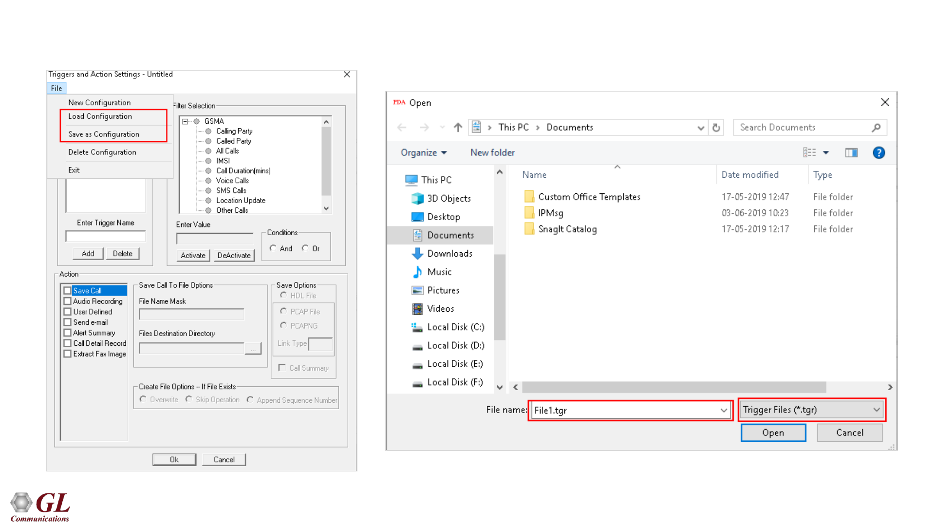
Load or Save Configurations
80
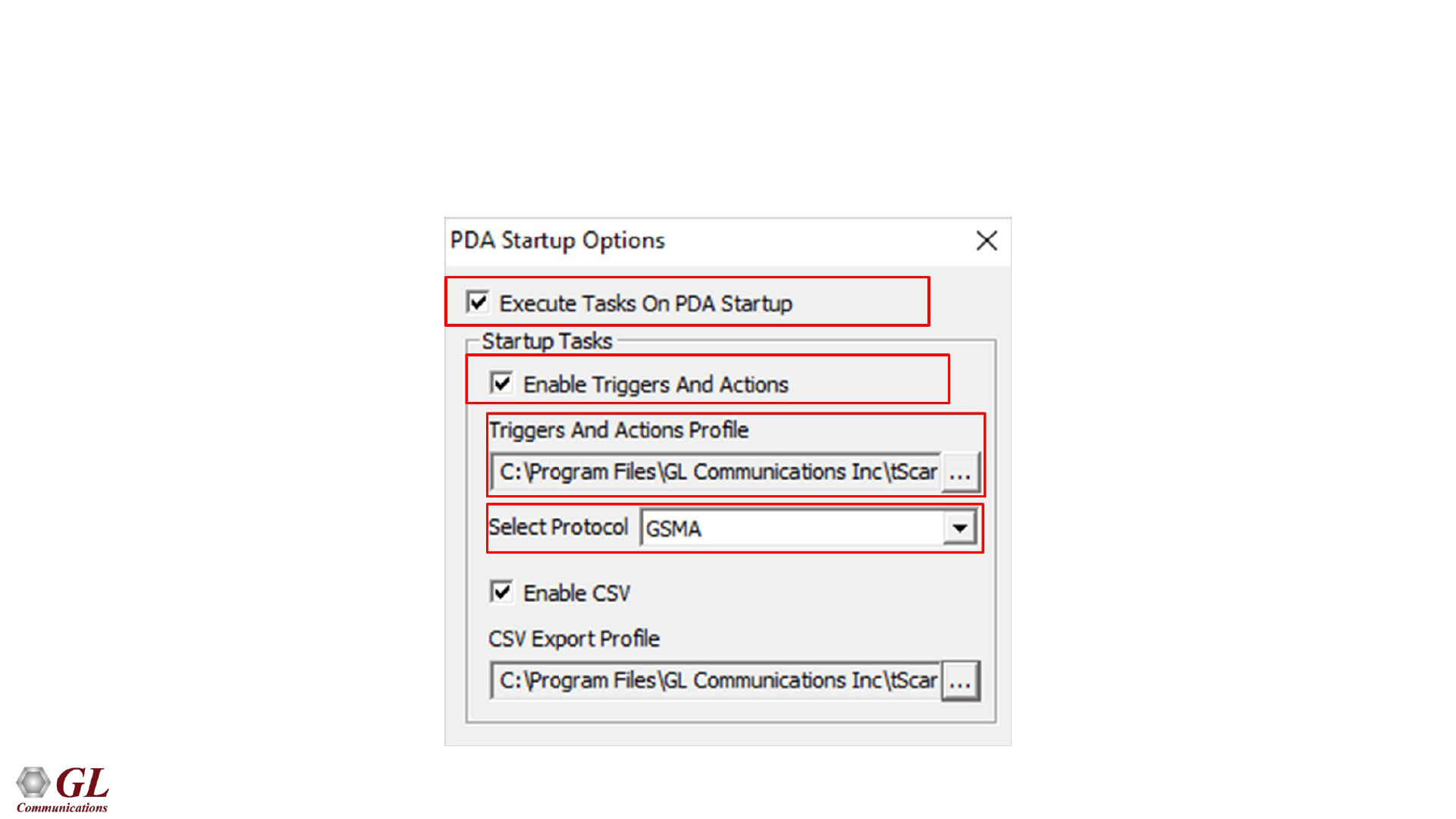
PDA Startup Options
• Allows user to configure start-up tasks which will be started automatically whenever PDA is launched
• Loads the selected Triggers and Actions profile while invoking PDA

81
Thank You
