
1
Stack in LC3 &
Interrupt Processing
(Chapters 10)
1
Subroutines in LC3
• we covered TRAP routines
• System calls to process I/O (or other system tasks)
• Written by system, called by user
ØResides as part of system code
• Steps: Call, Process, Return
• Subroutines – i.e., functions
• Written by user
• Called by user program
• Steps: Call, Process, Return
2

2
Finally. . last concept at Machine Level. . The
Stack: An abstract data type (ADT)
• An important abstraction you will encounter in many
applications
• Abstract Data Type
• Defined by behavior not implementation
• Stack
• Last in/First Out
• Many ways to implement
• Many uses in CS
Ø Interrupt drive I/O, Saving state of Processor, function calls, etc.
• Push/Pop
3
Stack: An Abstract Data Type
•An important abstraction that you will encounter
in many applications.
•Example: three uses --
•Interrupt-Driven I/O
• The rest of the story…
•Evaluating arithmetic expressions
• Store intermediate results on stack instead of in registers
Ø Do this in HW 5
•Data type conversion
• 2’s comp binary to ASCII strings
• You will read this on your own and use it in HW5 and Project 2
4
3
Stacks
•Simplest form of storage ?
•A LIFO (last-in first-out) storage structure.
• The first thing you put in is the last thing you take out.
• The last thing you put in is the first thing you take out.
•This means of access is what defines a stack,
not the specific implementation.
•Two main operations:
PUSH: add an item to the stack
• POP: remove an item from the stack
5
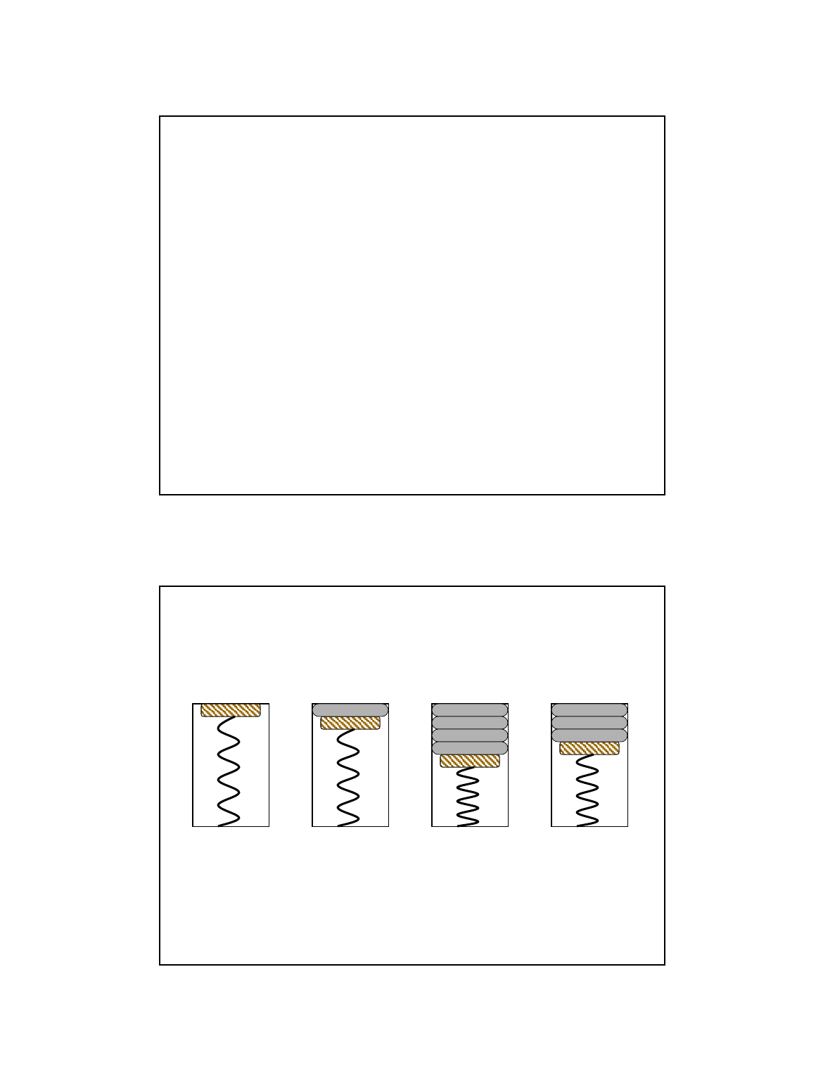
A Physical Stack
•Coin rest in the arm of an automobile
•First quarter out is the last quarter in.
1995 1996
1998
1982
1995
1998
1982
1995
Initial State After
One Push
After Three
More Pushes
After
One Pop
6
4
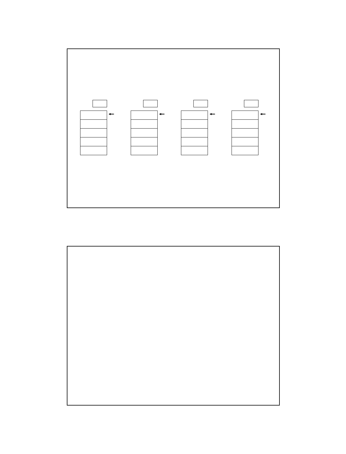
A Hardware Implementation
•Data items move between registers to memory
•
/ / / / / /
/ / / / / /
/ / / / / /
/ / / / / /
/ / / / / /
YesEmpty:
TOP
#18
/ / / / / /
/ / / / / /
/ / / / / /
/ / / / / /
NoEmpty:
TOP
#12
#5
#31
#18
/ / / / / /
NoEmpty:
TOP
#31
#18
/ / / / / /
/ / / / / /
/ / / / / /
NoEmpty:
TOP
Initial State After
One Push
After Three
More Pushes
After
Two Pops
7
Problems….
• Implement a stack as an array.
• Push will involve moving each element over 1:
• a(n+1) = a(n)
• a(0) = new_element
• Etc.
• So what’s the solution….
8
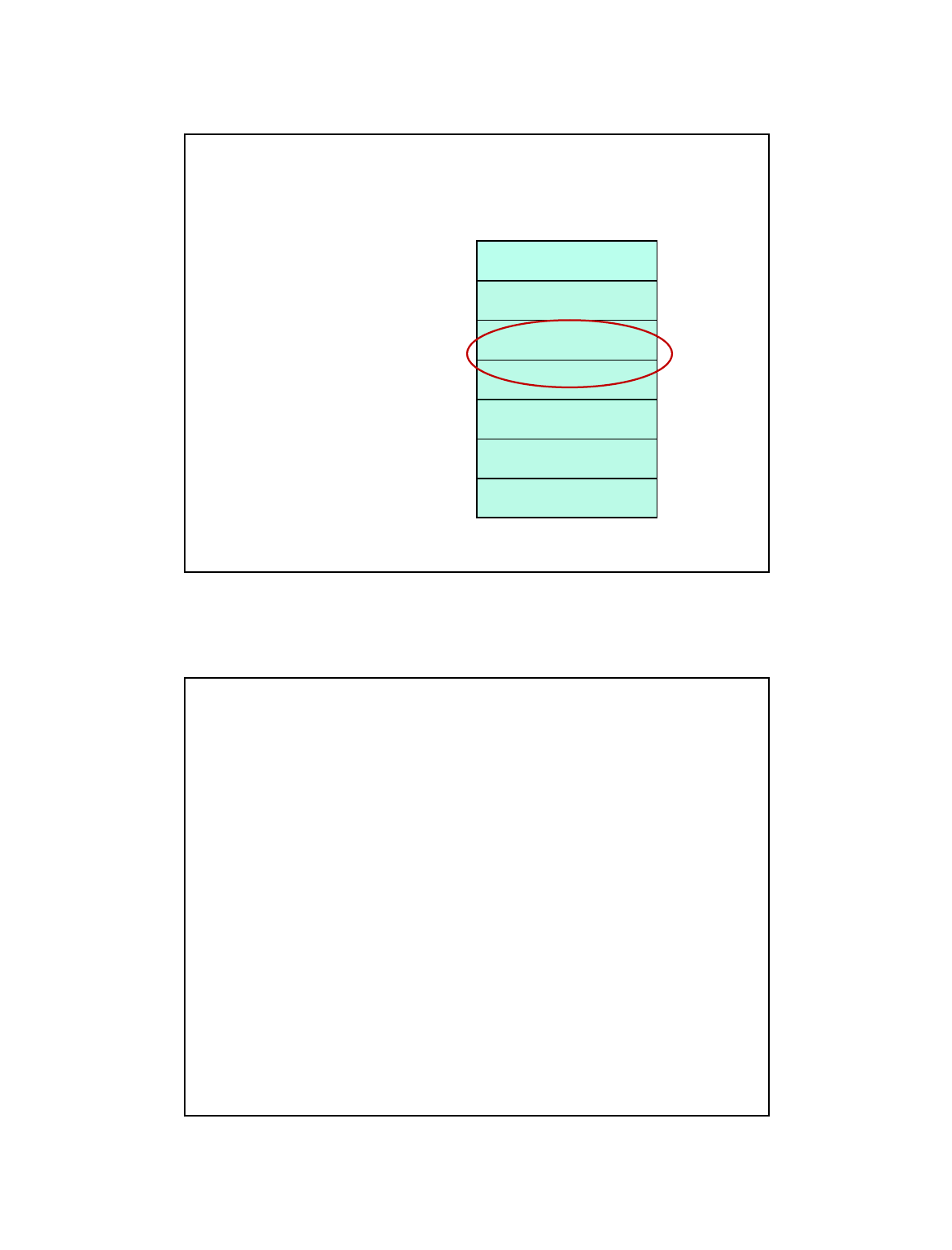
5
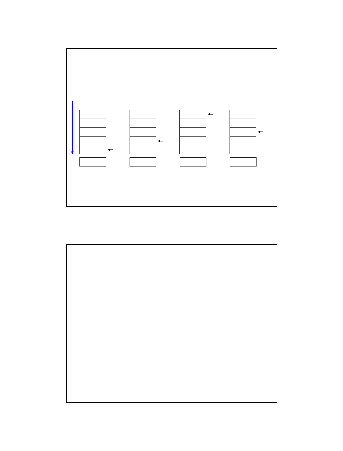
A Software Implementation
•Data items don't move in memory, just our idea about where
the TOP of the stack is.
• Note: stack “grows” towards lower numbered addresses
/ / / / / /
/ / / / / /
/ / / / / /
/ / / / / /
/ / / / / / TOP
/ / / / / /
/ / / / / /
/ / / / / /
#18
/ / / / / /
TOP
#12
#5
#31
#18
/ / / / / /
TOP
#12
#5
#31
#18
/ / / / / /
TOP
Initial State After
One Push
After Three
More Pushes
After
Two Pops
x4000 x3FFF x3FFC x3FFE
R6 R6 R6 R6
By convention, in LC3 R6 holds the Top of Stack (TOS) pointer.
every ISA specifies such a register
Memory addresses increase ‘downward’; bottom of stack has highest address
9
Question…State of stack
• R6 points to top of stack
•What happens after a push ?
•What happens after a pop ?
10

6
Basic Push and Pop Code
•For our implementation, stack grows downward
in address space
• (when item added, TOS moves closer to 0)
•Push: value in register R0 into the stack
• ADD R6, R6, #-1 ; decrement stack ptr
STR R0, R6, #0 ; store data (R0)
•Pop: value at top of stack into register R0
• LDR R0, R6, #0 ; load data from TOS
ADD R6, R6, #1 ; decrement stack ptr
11
Anything missing…?
•Detect underflow
• Trying to pop from empty stack
•Detect overflow
• Trying to push into a “full” stack
•Need to send a “signal” back to calling program indicating
success or failure of pop or push operations
12

7
Pop subroutine with Underflow Detection
•If we try to pop too many items,an underflow condition occurs.
• Check for underflow by checking TOS before removing data.
• Return status code in R5 (0 for success, 1 for underflow)
• Return value at TOS into R0
•POP LD R1, EMPTY ; EMPTY = -x4000
ADD R2, R6, R1 ; Compare stack pointer
BRz FAIL ;
LDR R0, R6, #0
ADD R6, R6, #1
AND R5, R5, #0 ; SUCCESS: R5 = 0
RET
FAIL AND R5, R5, #0 ; FAIL: R5 = 1
ADD R5, R5, #1
RET
EMPTY .FILL xC000
13
Push Subroutine with Overflow Detection
•If we try to push too many items,an overflow condition occurs.
• Check for underflow by checking TOS before adding data.
• Return status code in R5 (0 for success, 1 for overflow)
• Push value in R0 onto the stack
•PUSH LD R1, MAX ; MAX = -x3FFB
ADD R2, R6, R1 ; Compare stack pointer
BRz FAIL ;
ADD R6, R6, #-1
STR R0, R6, #0
AND R5, R5, #0 ; SUCCESS: R5 = 0
RET
FAIL AND R5, R5, #0 ; FAIL: R5 = 1
ADD R5, R5, #1
RET
MAX .FILL xC005
14

8
More Stack Use examples
•Simple calculator program
• Also illustrates use of subroutines
•Converting ASCII to Binary
• System always reads ASCII characters from terminal/input
• System operates on binary numbers
• Who does the conversion ?
ØNeed a subroutine
•Interrupts
• Interrupt driven I/O
Will need to understand stack concept and use it later to
implement high level language program execution
15
HW: Calculator using Stack
•Simulate a calculator using LC3
•You MUST read the Example in Chapter 10
• You will be required to implement it in Team homework
• various portions of the source code have been provided, but you have
to put them together and get them to work
ØThere are some integration issues you need to worry about – i.e.,
ignoring them will lead to bugs
• Source code can help with your Project 4 (and Homework 5)
ØYou can use any of the code provided
ØAvailable in electronic reserves on Blackboard
16
9
Arithmetic Using a Stack
•Instead of registers, some ISA's used a stack for
source and destination operations: a zero-address machine.
• Example:
ADD instruction pops two numbers from the stack,
adds them, and pushes the result to the stack.
•Evaluating (A+B)·(C+D) using a stack:
•(A,B,+)(C,D,+)*
• (1) push A
(2) push B
(3) ADD
(4) push C
(5) push D
(6) ADD
(7) MULTIPLY
(8) pop result
Why use a stack?
• Limited registers.
• Convenient calling convention
for subroutines.
• Algorithm naturally expressed
using FIFO data structure.
Historical note: HP calculators used reverse polish notation…similar to this
17
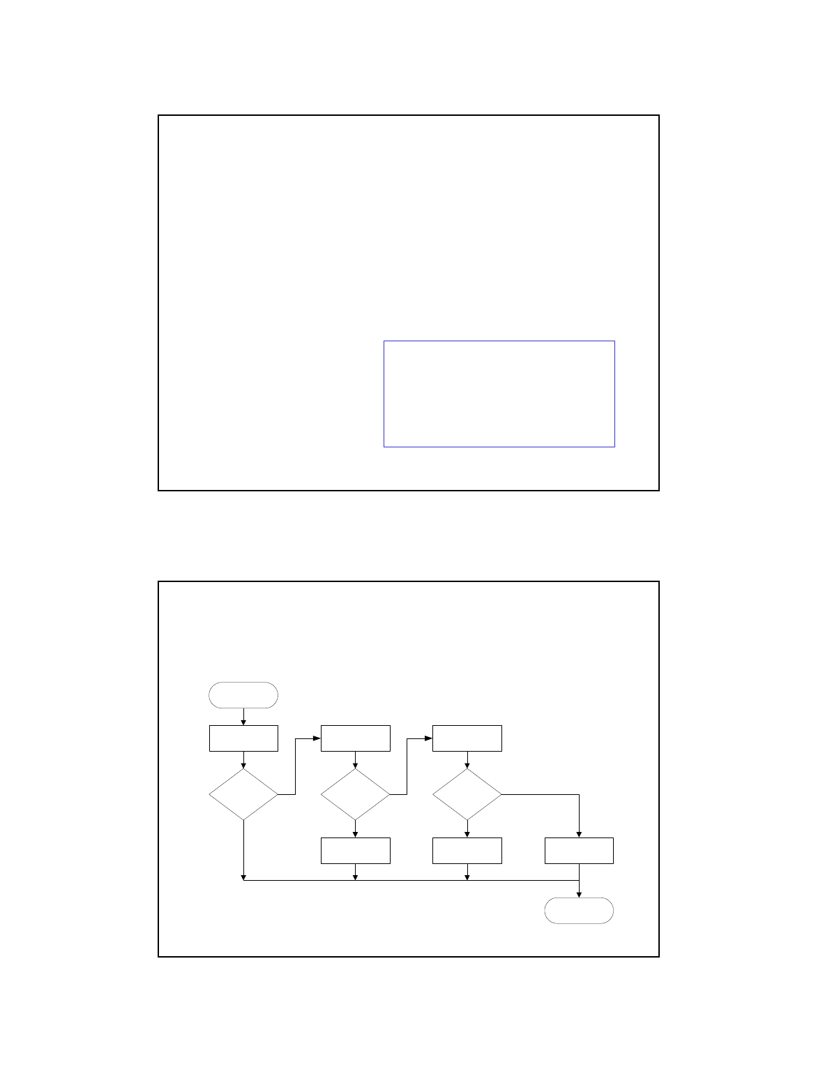
Example: So how does Add operation (OpAdd)
work on this calculator ?
•POP two values, ADD, then PUSH result.
START
POP POP
OK? OK?
ADD
Range
OK?
PUSH
RETURN
Put back bothPut back first
Yes
No
No No
Yes
Yes
18

10
Example: OpAdd
•
OpAdd JSR POP ; Get first operand.
ADD R5,R5,#0 ; Check for POP success.
BRp Exit ; If error, bail.
ADD R1,R0,#0 ; Make room for second.
JSR POP ; Get second operand.
ADD R5,R5,#0 ; Check for POP success.
BRp Restore1 ; If err, restore & bail.
ADD R0,R0,R1 ; Compute sum.
JSR RangeCheck ; Check size.
BRp Restore2 ; If err, restore & bail.
JSR PUSH ; Push sum onto stack.
RET
Restore2 ADD R6,R6,#-1 ; Decr stack ptr (undo POP)
Restore1 ADD R6,R6,#-1 ; Decr stack ptr
Exit RET
19
Data Type Conversion
• LC3 keyboard input routines read ASCII characters,
not binary values.
•Similarly, LC3 output routines write ASCII.
•You’ve seen this program:
• IN ; input from keybd into R0
ADD R1, R0, #0 ; move to R1
IN ; read next input from keybd
ADD R2, R0, #0 ; move to R2 add two inputs
ADD R0, R1,R2 ; add the two inputs
OUT ; print result
•What happened ?
• Why? ASCII '2' (x32) + ASCII '3' (x33) = ASCII 'e' (x65)
20
11
ASCII to Binary
•Useful to deal with mult-digit decimal numbers
•Assume we've read three ASCII digits (e.g., "259")
into a memory buffer.
•How do we convert this to a number
we can use?
• Convert first character to digit (subtract x30)
and multiply by 100.
• Convert second character to digit and
multiply by 10.
• Convert third character to digit.
• Add the three digits together.
x32
x35
x39
'2'
'5'
'9'
Curious ? Look up atoi function in C…
21
Multiplication via a Lookup Table
•How can we multiply a number by 100?
• One approach:
Add number to itself 100 times.
• Another approach:
Add 100 to itself <number> times. (Better if number < 100.)
•Since we have a small range of numbers (0-9),
use number as an index into a lookup table.
• Entry 0: 0 x 100 = 0
Entry 1: 1 x 100 = 100
Entry 2: 2 x 100 = 200
Entry 3: 3 x 100 = 300
etc.
22

12
Binary to ASCII Conversion
•Converting a 2's complement binary value to
a three-digit decimal number
• Resulting characters can be output using OUT
•Instead of multiplying, we need to divide by 100
to get hundreds digit.
• Why wouldn't we use a lookup table for this problem?
• Subtract 100 repeatedly from number to divide.
•First, check whether number is negative.
• Write sign character (+ or -) to buffer and make positive.
23
More Stack uses…
•Interrupt processing
•Will need to understand stack concept and use it later to
implement high level language program execution
24

13
Recall: Interrupt-Driven I/O
• Two ways to process I/O
• Polling: CPU waits for input device
• Interrupt driven: device signals when it is ready
• Why?
• Polling consumes a lot of cycles,
especially for rare events – these cycles could be used to do useful
computations.
• Example: Process previous input while waiting for network/disk.
25
Interrupt Processing
External device can:
(1) Force currently executing program to stop;
(2) Have the processor satisfy the device’s needs; and
(3) Resume the stopped program as if nothing happened.
26
14
Interrupt-Driven I/O
•To implement an interrupt mechanism, we need:
• A way for the I/O device to signal the CPU that an
interesting event has occurred.
• A way for the CPU to test whether the interrupt signal is set
and whether its priority is higher than the current program.
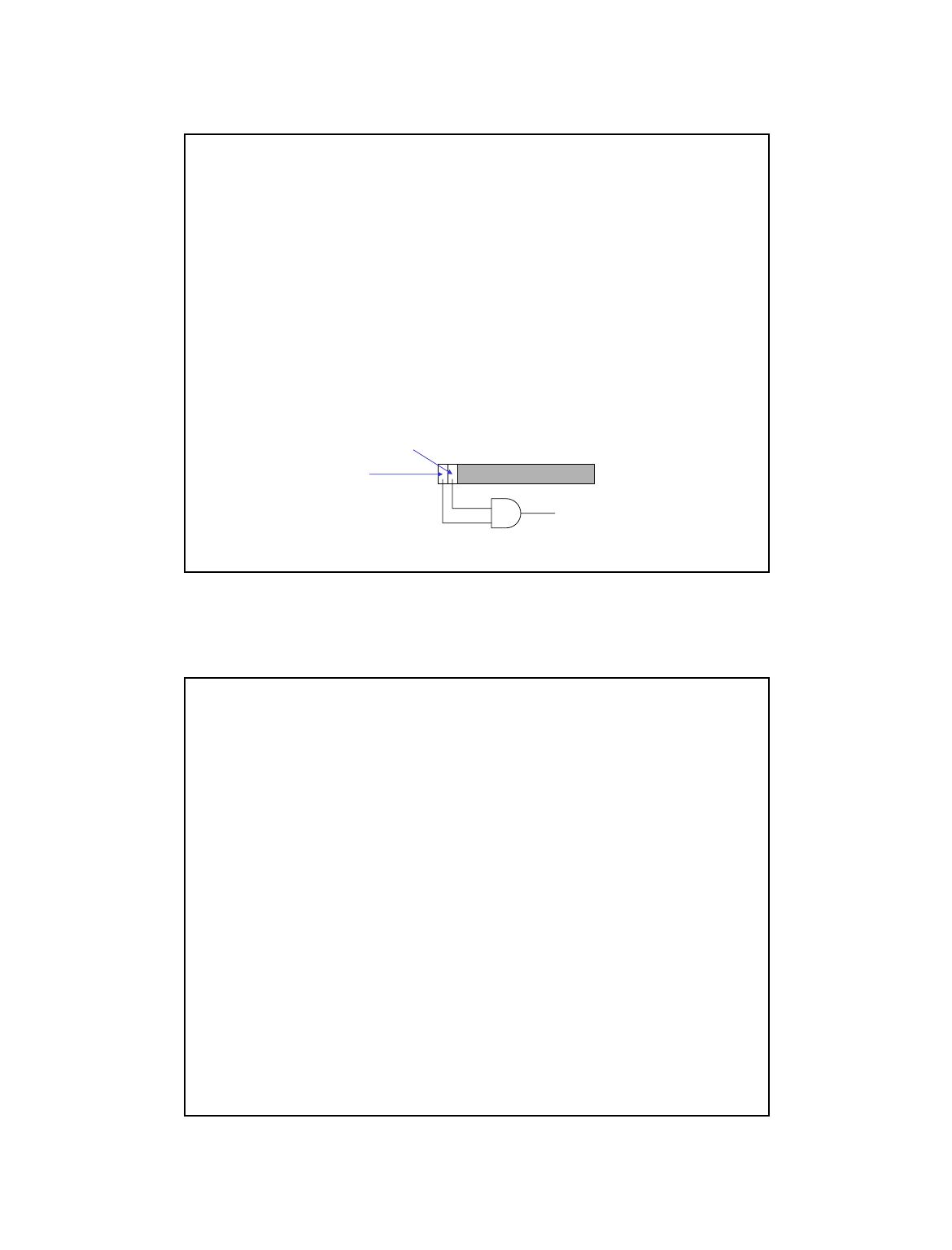
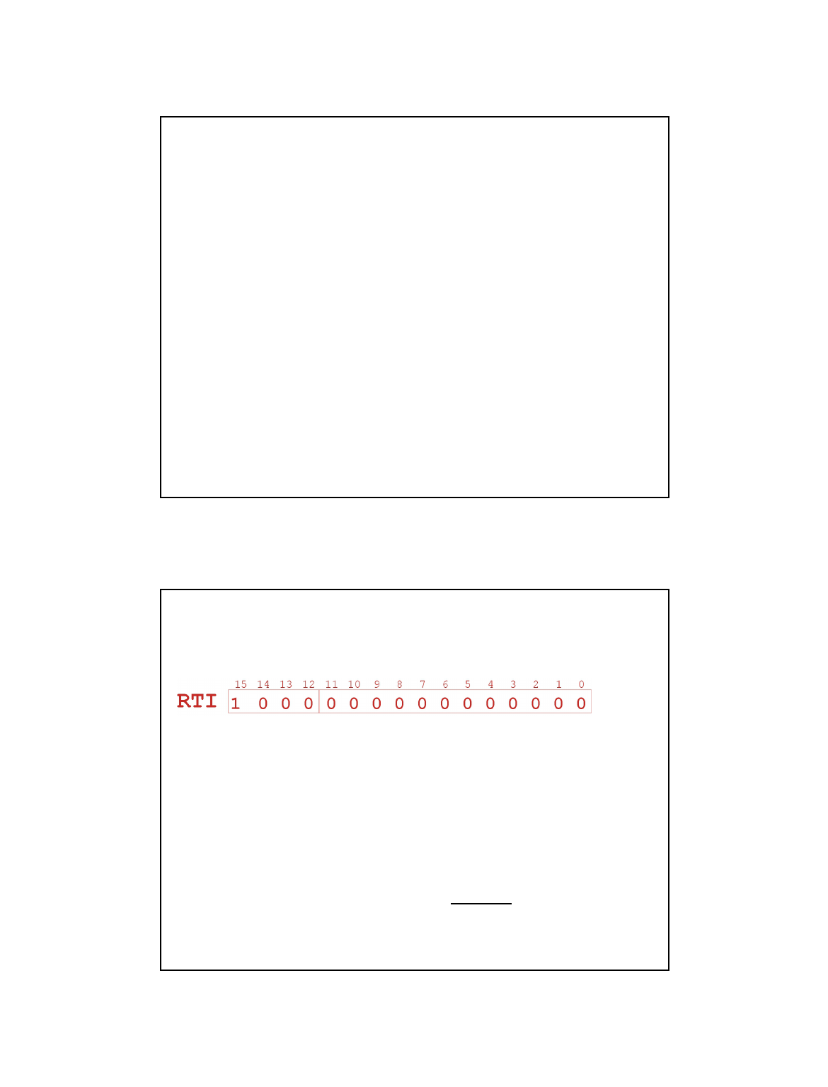
•Generating Signal
• Software sets "interrupt enable" bit in device register.
• When ready bit is set and IE bit is set, interrupt is signaled.
KBSR
15 14 0
ready bit
13
interrupt enable bit
interrupt signal
to processor
27
Priority
•Every instruction executes at a stated level of urgency.
•LC-3: 8 priority levels (PL0-PL7)
• Example:
Ø email program runs at PL0.
Ø Nuclear power correction program runs at PL6.
• It’s OK for PL6 device to interrupt PL0 program,
but not the other way around.
•Priority encoder selects highest-priority device,
compares to current processor priority level,
and generates interrupt signal if appropriate.
28
15
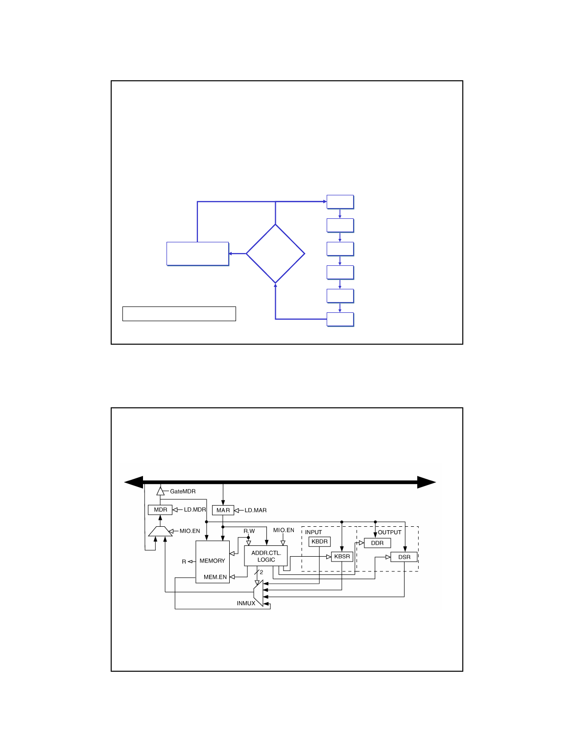
Testing for Interrupt Signal
•CPU looks at signal between STORE and FETCH phases.
•If not set, continues with next instruction.
•If set, transfers control to interrupt service routine.
EA
OP
EX
S
F
D
interrupt
signal?
Transfer to
ISR
NO
YES
More details in Chapter 10.
29
Full Implementation of LC-3 Memory-Mapped I/O
Because of interrupt enable bits, status registers (KBSR/DSR)
must be written, as well as read.
30
16
Interrupt-Driven I/O
•Interrupts processing:
1. External device signals need to be serviced.
2. Processor saves state and starts service routine.
3. When finished, processor restores state and resumes program.
•How do steps (2) and (3) occur,
involves a stack.
Interrupt is an
unscripted subroutine call
,
triggered by an external event.
31
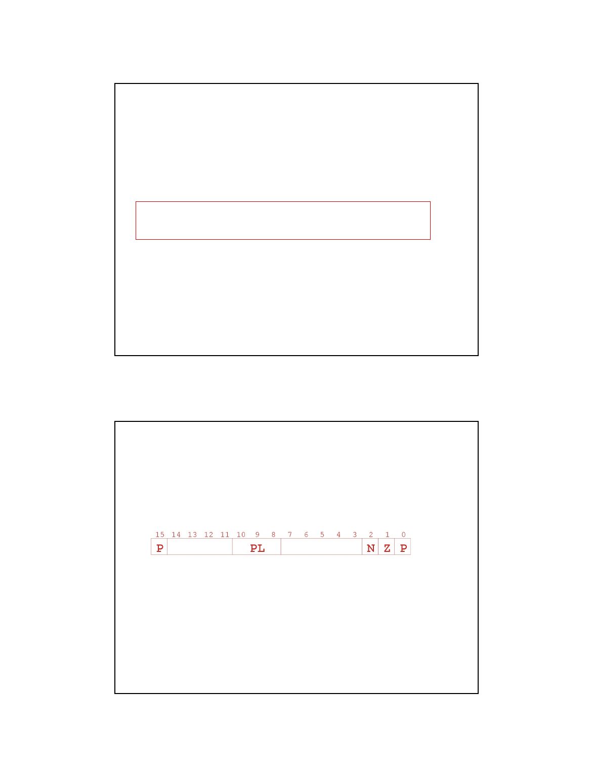
Processor State
•What state is needed to completely capture the
state of a running process?
•Processor Status Register
• Privilege [15], Priority Level [10:8], Condition Codes [2:0]
•Program Counter
• Pointer to next instruction to be executed.
•Registers
• All temporary state of the process that’s not stored in memory.
Ø Can be saved by Interrupt processing routine (similar to TRAP routines)
32

17
Where to Save Processor State?
•Can’t use registers.
• Programmer doesn’t know when interrupt might occur,
so she can’t prepare by saving critical registers.
• When resuming, need to restore state exactly as it was.
•Memory allocated by service routine?
• Must save state before invoking routine,
so we wouldn’t know where.
• Also, interrupts may be nested –
that is, an interrupt service routine might also get interrupted!
•Use a stack!
• Location of stack “hard-wired”.
• Push state to save, pop to restore.
33
Supervisor Stack
•A special region of memory used as the stack
for interrupt service routines.
• Initial Supervisor Stack Pointer (SSP) stored in Saved.SSP.
• Another register for storing User Stack Pointer (USP):
Saved.USP.
•Want to use R6 as stack pointer.
• So that our PUSH/POP routines still work.
•When switching from User mode to Supervisor mode (as
result of interrupt), save R6 to Saved.USP.
34
18
Invoking the Service Routine – The Details
1. If Priv = 1 (user),
Saved.USP = R6, then R6 = Saved.SSP.
2. Push PSR and PC to Supervisor Stack.
3. Set PSR[15] = 0 (supervisor mode).
4. Set PSR[10:8] = priority of interrupt being serviced.
5. Set PSR[2:0] = 0.
6. Set MAR = x01vv, where vv = 8-bit interrupt vector
provided by interrupting device (e.g., keyboard = x80).
7. Load memory location (M[x01vv]) into MDR.
8. Set PC = MDR; now first instruction of ISR will be fetched.
Note: This all happens between
the STORE RESULT of the last user instruction and
the FETCH of the first ISR instruction.
35
Returning from Interrupt
• Special instruction – RTI – that restores state.
1. Pop PC from supervisor stack. (PC = M[R6]; R6 = R6 + 1)
2. Pop PSR from supervisor stack. (PSR = M[R6]; R6 = R6 + 1)
3. If PSR[15] = 1, R6 = Saved.USP.
(If going back to user mode, need to restore User Stack Pointer.)
• RTI is a privileged instruction.
• Can only be executed in Supervisor Mode.
• If executed in User Mode, causes an exception.
(More about that later.)
36
19
Example (1)
/ / / / / /
/ / / / / /
/ / / / / /
/ / / / / /
/ / / / / /
x3006
PC
Program A
ADD
x3006
Executing ADD at location x3006 when Device B interrupts.
Saved.SSP
37
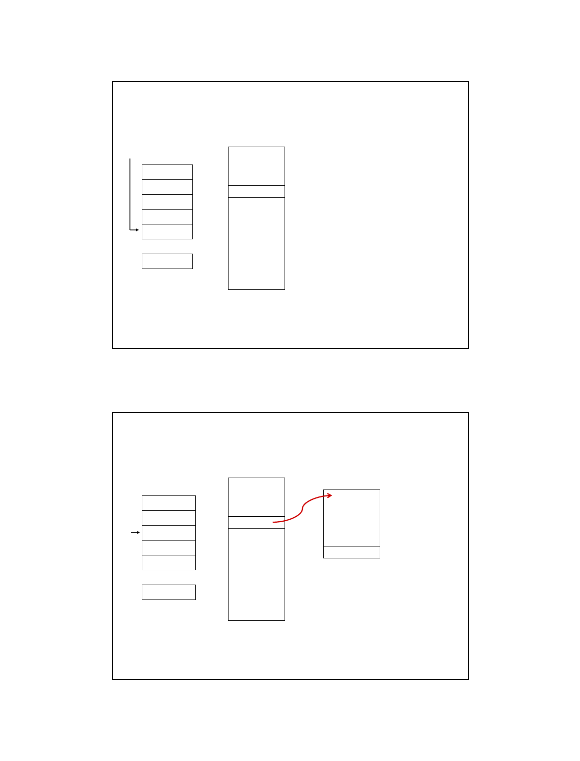
Example (2)
/ / / / / /
x3007
PSR for A
/ / / / / /
/ / / / / /
x6200
PC
R6
Program A
ADD
x3006
Saved.USP = R6. R6 = Saved.SSP.
Push PSR and PC onto stack, then transfer to
Device B service routine (at x6200).
x6200
ISR for
Device B
x6210
RTI
38
20
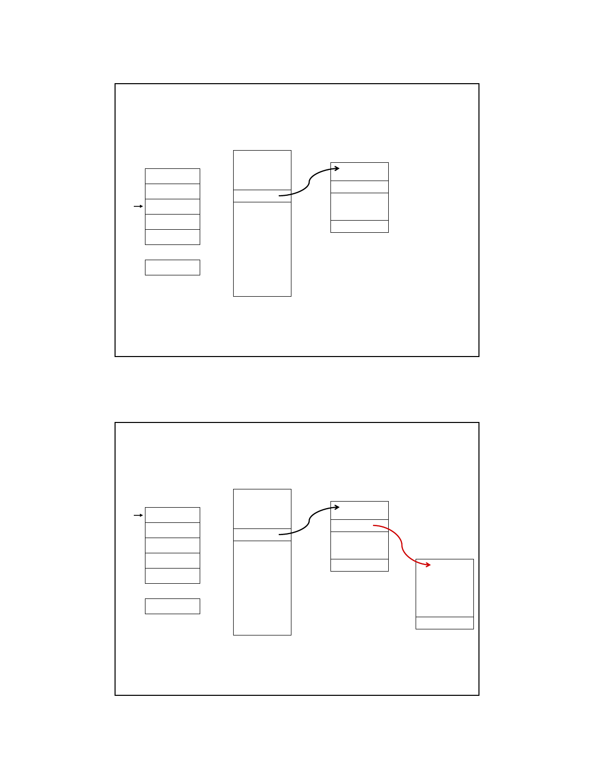
Example (3)
/ / / / / /
x3007
PSR for A
/ / / / / /
/ / / / / /
x6203
PC
R6
Program A
ADD
x3006
Executing AND at x6202 when Device C interrupts.
x6200
ISR for
Device B
AND
x6202
x6210
RTI
39
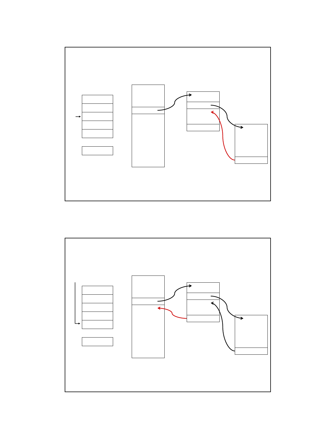
Example (4)
/ / / / / /
x3007
PSR for A
x6203
PSR for B
x6300
PC
R6
Program A
ADD
x3006
x6200
ISR for
Device B
AND
x6202
ISR for
Device C
Push PSR and PC onto stack, then transfer to
Device C service routine (at x6300).
x6300
x6315
RTI
x6210
RTI
40
21
Example (5)
/ / / / / /
x3007
PSR for A
x6203
PSR for B
x6203
PC
R6
Program A
ADD
x3006
x6200
ISR for
Device B
AND
x6202
ISR for
Device C
Execute RTI at x6315; pop PC and PSR from stack.
x6300
x6315
RTI
x6210
RTI
41
Example (6)
/ / / / / /
x3007
PSR for A
x6203
PSR for B
x3007
PC
Program A
ADD
x3006
x6200
ISR for
Device B
AND
x6202
ISR for
Device C
Execute RTI at x6210; pop PSR and PC from stack.
Restore R6. Continue Program A as if nothing happened.
x6300
x6315
RTI
x6210
RTI
Saved.SSP
42

22
Exception: Internal Interrupt
•When something unexpected happens
inside the processor, it may cause an exception.
•Examples:
• Privileged operation (e.g., RTI in user mode)
• Executing an illegal opcode
• Divide by zero
• Accessing an illegal address (e.g., protected system memory)
•Handled just like an interrupt
• Vector is determined internally by type of exception
• Priority is the same as running program
43
What Next ?
44
23
Problem Transformation
- levels of abstraction
Natural Language
Algorithm
Program
Machine Architecture
Devices
Micro-architecture
Logic Circuits
Interaction and
Translation from
High level to ISA
How do user programs
get executed?
45
What to study next..
•How are high level programs executed on the processor ?
• Review some aspects of C
ØHow are operators implemented?
• Function calls and recursion
ØHow does the system support this?
– Any guesses?
• Memory
ØConcept of virtual memory
•Performance
• How “efficient is your program” ?
46
