
NVIDIA OptiX 7.7
Programming Guide
12 July 2023
Version 1.15

NVIDIA OptiX 7.7 – Programming Guide
Copyright Information
2023 NVIDIA Corporation. All rights reserved. Document build number rev370822
ii NVIDIA OptiX 7.7 ± Programming Guide © 2023 NVIDIA Corporation

Contents
Preface 1
Terms used in this document . . . . . . . . . . . . . . . . . . . . . . . . . . . . . . . . . . . . . . . . . . . 1
1
Overview 3
2
Basic concepts and definitions 5
2.1
Program . . . . . . . . . . . . . . . . . . . . . . . . . . . . . . . . . . . . . . . . . . . . . . . . . . . . . . . . . . . . 5
2.2 Program and data model . . . . . . . . . . . . . . . . . . . . . . . . . . . . . . . . . . . . . . . . . . . . . . 5
2.2.1
Shader binding table . . . . . . . . . . . . . . . . . . . . . . . . . . . . . . . . . . . . . . . . . . . . . . 6
2.2.2
Ray payload . . . . . . . . . . . . . . . . . . . . . . . . . . . . . . . . . . . . . . . . . . . . . . . . . . . . . 6
2.2.3
Primitive attributes . . . . . . . . . . . . . . . . . . . . . . . . . . . . . . . . . . . . . . . . . . . . . . . . 7
2.2.4 Buffer . . . . . . . . . . . . . . . . . . . . . . . . . . . . . . . . . . . . . . . . . . . . . . . . . . . . . . . . . . 7
2.3
Acceleration structures . . . . . . . . . . . . . . . . . . . . . . . . . . . . . . . . . . . . . . . . . . . . . . . . 7
2.4
Opacity micromaps . . . . . . . . . . . . . . . . . . . . . . . . . . . . . . . . . . . . . . . . . . . . . . . . . . . 7
2.5 Traversing the scene graph . . . . . . . . . . . . . . . . . . . . . . . . . . . . . . . . . . . . . . . . . . . . . 7
2.6
Ray tracing with NVIDIA OptiX . . . . . . . . . . . . . . . . . . . . . . . . . . . . . . . . . . . . . . . . 9
3
Implementation principles 11
3.1
Error handling . . . . . . . . . . . . . . . . . . . . . . . . . . . . . . . . . . . . . . . . . . . . . . . . . . . . . . 11
3.2 Thread safety . . . . . . . . . . . . . . . . . . . . . . . . . . . . . . . . . . . . . . . . . . . . . . . . . . . . . . . 11
3.3
Stateless model . . . . . . . . . . . . . . . . . . . . . . . . . . . . . . . . . . . . . . . . . . . . . . . . . . . . . 11
3.4
Asynchronous execution . . . . . . . . . . . . . . . . . . . . . . . . . . . . . . . . . . . . . . . . . . . . . . 11
3.5
Opaque types . . . . . . . . . . . . . . . . . . . . . . . . . . . . . . . . . . . . . . . . . . . . . . . . . . . . . . 11
3.6 Function table and entry function . . . . . . . . . . . . . . . . . . . . . . . . . . . . . . . . . . . . . . . 11
4
Context 15
4.1
Sending messages with a callback function . . . . . . . . . . . . . . . . . . . . . . . . . . . . . . . 16
4.2
Compilation caching . . . . . . . . . . . . . . . . . . . . . . . . . . . . . . . . . . . . . . . . . . . . . . . . . 17
4.3 Validation mode . . . . . . . . . . . . . . . . . . . . . . . . . . . . . . . . . . . . . . . . . . . . . . . . . . . . 18
5
Acceleration structures 19
5.1
Primitive build inputs . . . . . . . . . . . . . . . . . . . . . . . . . . . . . . . . . . . . . . . . . . . . . . . . 21
5.2
Curve build inputs . . . . . . . . . . . . . . . . . . . . . . . . . . . . . . . . . . . . . . . . . . . . . . . . . . 24
5.3 Sphere build inputs . . . . . . . . . . . . . . . . . . . . . . . . . . . . . . . . . . . . . . . . . . . . . . . . . . 25
5.4
Instance build inputs . . . . . . . . . . . . . . . . . . . . . . . . . . . . . . . . . . . . . . . . . . . . . . . . . 26
5.5
Build flags . . . . . . . . . . . . . . . . . . . . . . . . . . . . . . . . . . . . . . . . . . . . . . . . . . . . . . . . . 27
5.6 Dynamic updates . . . . . . . . . . . . . . . . . . . . . . . . . . . . . . . . . . . . . . . . . . . . . . . . . . . 28
5.7
Relocation . . . . . . . . . . . . . . . . . . . . . . . . . . . . . . . . . . . . . . . . . . . . . . . . . . . . . . . . . 29
© 2023 NVIDIA Corporation NVIDIA OptiX 7.7 ± Programming Guide iii

5.8 Compacting acceleration structures . . . . . . . . . . . . . . . . . . . . . . . . . . . . . . . . . . . . . 31
5.9
Traversable objects . . . . . . . . . . . . . . . . . . . . . . . . . . . . . . . . . . . . . . . . . . . . . . . . . . 33
5.9.1 Traversal of a single geometry acceleration structure . . . . . . . . . . . . . . . . . . . . 34
5.10
Motion blur . . . . . . . . . . . . . . . . . . . . . . . . . . . . . . . . . . . . . . . . . . . . . . . . . . . . . . . . 34
5.10.1
Basics . . . . . . . . . . . . . . . . . . . . . . . . . . . . . . . . . . . . . . . . . . . . . . . . . . . . . . . . . 34
5.10.2
Motion geometry acceleration structure . . . . . . . . . . . . . . . . . . . . . . . . . . . . . . 36
5.10.3 Motion instance acceleration structure . . . . . . . . . . . . . . . . . . . . . . . . . . . . . . . 37
5.10.4
Motion matrix transform . . . . . . . . . . . . . . . . . . . . . . . . . . . . . . . . . . . . . . . . . . 38
5.10.5
Motion scale/rotate/translate transform . . . . . . . . . . . . . . . . . . . . . . . . . . . . . . 39
5.10.6 Transforms trade-offs . . . . . . . . . . . . . . . . . . . . . . . . . . . . . . . . . . . . . . . . . . . . . 40
5.11
Opacity micromaps . . . . . . . . . . . . . . . . . . . . . . . . . . . . . . . . . . . . . . . . . . . . . . . . . . 41
5.11.1
Opacity micromap arrays . . . . . . . . . . . . . . . . . . . . . . . . . . . . . . . . . . . . . . . . . . 42
5.11.2
Usage . . . . . . . . . . . . . . . . . . . . . . . . . . . . . . . . . . . . . . . . . . . . . . . . . . . . . . . . . 44
5.11.2.1 Construction of the geometry acceleration structure . . . . . . . . . . . . . . . . . 44
5.11.2.2
Traversal . . . . . . . . . . . . . . . . . . . . . . . . . . . . . . . . . . . . . . . . . . . . . . . . . . . 46
5.11.3
Encoding . . . . . . . . . . . . . . . . . . . . . . . . . . . . . . . . . . . . . . . . . . . . . . . . . . . . . . . 47
5.12 Displaced micro-meshes . . . . . . . . . . . . . . . . . . . . . . . . . . . . . . . . . . . . . . . . . . . . . . 47
5.12.1
Displaced micro-meshes . . . . . . . . . . . . . . . . . . . . . . . . . . . . . . . . . . . . . . . . . . . 48
5.12.2
Displacement micro-maps . . . . . . . . . . . . . . . . . . . . . . . . . . . . . . . . . . . . . . . . . 50
5.12.2.1
Displacements blocks . . . . . . . . . . . . . . . . . . . . . . . . . . . . . . . . . . . . . . . . . 53
5.12.2.1.1 Uncompressed displacement block format . . . . . . . . . . . . . . . . . . . . . . 54
5.12.2.1.2
Compressed displacement block formats . . . . . . . . . . . . . . . . . . . . . . . 54
5.12.2.2
Edge decimation . . . . . . . . . . . . . . . . . . . . . . . . . . . . . . . . . . . . . . . . . . . . . 57
5.12.3
Displaced micro-mesh API . . . . . . . . . . . . . . . . . . . . . . . . . . . . . . . . . . . . . . . . . 58
5.12.3.1 Displacement micro-map arrays . . . . . . . . . . . . . . . . . . . . . . . . . . . . . . . . . 58
5.12.3.2
Geometry acceleration structure build for DMM triangles . . . . . . . . . . . . . 60
6
Program pipeline creation 61
6.1
Program input . . . . . . . . . . . . . . . . . . . . . . . . . . . . . . . . . . . . . . . . . . . . . . . . . . . . . . 62
6.2 Programming model . . . . . . . . . . . . . . . . . . . . . . . . . . . . . . . . . . . . . . . . . . . . . . . . . 63
6.3
Module creation . . . . . . . . . . . . . . . . . . . . . . . . . . . . . . . . . . . . . . . . . . . . . . . . . . . . 64
6.4
Pipeline launch parameter . . . . . . . . . . . . . . . . . . . . . . . . . . . . . . . . . . . . . . . . . . . . 66
6.4.1 Parameter specialization . . . . . . . . . . . . . . . . . . . . . . . . . . . . . . . . . . . . . . . . . . 66
6.5
Program group creation . . . . . . . . . . . . . . . . . . . . . . . . . . . . . . . . . . . . . . . . . . . . . . 69
6.6
Pipeline linking . . . . . . . . . . . . . . . . . . . . . . . . . . . . . . . . . . . . . . . . . . . . . . . . . . . . . 72
6.7
Pipeline stack size . . . . . . . . . . . . . . . . . . . . . . . . . . . . . . . . . . . . . . . . . . . . . . . . . . . 73
6.7.1 Constructing a path tracer . . . . . . . . . . . . . . . . . . . . . . . . . . . . . . . . . . . . . . . . . 75
6.8
Compilation cache . . . . . . . . . . . . . . . . . . . . . . . . . . . . . . . . . . . . . . . . . . . . . . . . . . . 75
7
Shader binding table 77
7.1
Records . . . . . . . . . . . . . . . . . . . . . . . . . . . . . . . . . . . . . . . . . . . . . . . . . . . . . . . . . . . 77
7.2 Layout . . . . . . . . . . . . . . . . . . . . . . . . . . . . . . . . . . . . . . . . . . . . . . . . . . . . . . . . . . . . 78
7.3
Acceleration structures . . . . . . . . . . . . . . . . . . . . . . . . . . . . . . . . . . . . . . . . . . . . . . . 79
7.3.1 SBT instance offset . . . . . . . . . . . . . . . . . . . . . . . . . . . . . . . . . . . . . . . . . . . . . . . 79
iv NVIDIA OptiX 7.7 ± Programming Guide © 2023 NVIDIA Corporation

7.3.2 SBT geometry-AS index . . . . . . . . . . . . . . . . . . . . . . . . . . . . . . . . . . . . . . . . . . . 79
7.3.3
SBT trace offset . . . . . . . . . . . . . . . . . . . . . . . . . . . . . . . . . . . . . . . . . . . . . . . . . . 81
7.3.4 SBT trace stride . . . . . . . . . . . . . . . . . . . . . . . . . . . . . . . . . . . . . . . . . . . . . . . . . . 81
7.3.5
Example SBT for a scene . . . . . . . . . . . . . . . . . . . . . . . . . . . . . . . . . . . . . . . . . . . 81
7.4
SBT record access on device . . . . . . . . . . . . . . . . . . . . . . . . . . . . . . . . . . . . . . . . . . . 83
8
Curves and spheres 85
8.1 Differences between curves, spheres, and triangles . . . . . . . . . . . . . . . . . . . . . . . . . 85
8.2
Splitting curve segments . . . . . . . . . . . . . . . . . . . . . . . . . . . . . . . . . . . . . . . . . . . . . . 86
8.3
Curves and the hit program . . . . . . . . . . . . . . . . . . . . . . . . . . . . . . . . . . . . . . . . . . . 86
8.4
Spheres and the hit program . . . . . . . . . . . . . . . . . . . . . . . . . . . . . . . . . . . . . . . . . . . 87
8.5 Interpolating curve endpoints . . . . . . . . . . . . . . . . . . . . . . . . . . . . . . . . . . . . . . . . . 87
8.6
Back-face culling . . . . . . . . . . . . . . . . . . . . . . . . . . . . . . . . . . . . . . . . . . . . . . . . . . . . 88
8.7
Limitations . . . . . . . . . . . . . . . . . . . . . . . . . . . . . . . . . . . . . . . . . . . . . . . . . . . . . . . . 88
9
Ray generation launches 91
10
Limits 93
11
Device-side functions 95
11.1
Launch index . . . . . . . . . . . . . . . . . . . . . . . . . . . . . . . . . . . . . . . . . . . . . . . . . . . . . . . 97
11.2
Trace . . . . . . . . . . . . . . . . . . . . . . . . . . . . . . . . . . . . . . . . . . . . . . . . . . . . . . . . . . . . . 97
11.3 Payload access . . . . . . . . . . . . . . . . . . . . . . . . . . . . . . . . . . . . . . . . . . . . . . . . . . . . . . 99
11.4
Reporting intersections and attribute access . . . . . . . . . . . . . . . . . . . . . . . . . . . . . 100
11.5
Ray information . . . . . . . . . . . . . . . . . . . . . . . . . . . . . . . . . . . . . . . . . . . . . . . . . . . 101
11.6
Undefined values . . . . . . . . . . . . . . . . . . . . . . . . . . . . . . . . . . . . . . . . . . . . . . . . . . 102
11.7 Intersection information . . . . . . . . . . . . . . . . . . . . . . . . . . . . . . . . . . . . . . . . . . . . . 102
11.8
SBT record data . . . . . . . . . . . . . . . . . . . . . . . . . . . . . . . . . . . . . . . . . . . . . . . . . . . . 103
11.9
Vertex random access . . . . . . . . . . . . . . . . . . . . . . . . . . . . . . . . . . . . . . . . . . . . . . . 103
11.9.1 Displaced micro-mesh triangle vertices . . . . . . . . . . . . . . . . . . . . . . . . . . . . . . 104
11.10
Geometry acceleration structure motion options . . . . . . . . . . . . . . . . . . . . . . . . . . 106
11.11
Transform list . . . . . . . . . . . . . . . . . . . . . . . . . . . . . . . . . . . . . . . . . . . . . . . . . . . . . 106
11.12
Instance random access . . . . . . . . . . . . . . . . . . . . . . . . . . . . . . . . . . . . . . . . . . . . . . 108
11.13 Terminating or ignoring traversal . . . . . . . . . . . . . . . . . . . . . . . . . . . . . . . . . . . . . . 109
11.14
Exceptions . . . . . . . . . . . . . . . . . . . . . . . . . . . . . . . . . . . . . . . . . . . . . . . . . . . . . . . . 109
12
Payload 115
13
Callables 119
13.1 Callable programs . . . . . . . . . . . . . . . . . . . . . . . . . . . . . . . . . . . . . . . . . . . . . . . . . . 119
13.2
Non-inlined functions . . . . . . . . . . . . . . . . . . . . . . . . . . . . . . . . . . . . . . . . . . . . . . . 120
14
NVIDIA AI Denoiser 121
14.1
Functions and data structures for denoising . . . . . . . . . . . . . . . . . . . . . . . . . . . . . 122
14.1.1 Structure and use of image buffers . . . . . . . . . . . . . . . . . . . . . . . . . . . . . . . . . 124
14.1.2
Temporal denoising modes . . . . . . . . . . . . . . . . . . . . . . . . . . . . . . . . . . . . . . . 126
14.1.3
Allocating denoiser memory . . . . . . . . . . . . . . . . . . . . . . . . . . . . . . . . . . . . . . 127
© 2023 NVIDIA Corporation NVIDIA OptiX 7.7 ± Programming Guide v

14.1.4 Using the denoiser . . . . . . . . . . . . . . . . . . . . . . . . . . . . . . . . . . . . . . . . . . . . . . 128
14.1.5
Calculating the HDR average color of the AOV model . . . . . . . . . . . . . . . . . . 131
14.1.6 Calculating the HDR intensity parameter . . . . . . . . . . . . . . . . . . . . . . . . . . . . 131
14.2
Using image tiles with the denoiser . . . . . . . . . . . . . . . . . . . . . . . . . . . . . . . . . . . . 132
vi NVIDIA OptiX 7.7 ± Programming Guide © 2023 NVIDIA Corporation

Preface
DirectX Raytracing (DXR),
1
Vulkan
2
(through the VK_NV_ray_tracing extension) and the
NVIDIA OptiX™ API
3
employ a similar programming model to support ray tracing
capabilities. DXR and Vulkan enable ray tracing effects in raster-based gaming and
visualization applications. NVIDIA OptiX is intended for ray tracing applications that use
NVIDIA
®
CUDA
®
technology, such as:
•
Film and television visual effects
•
Computer-aided design for engineering and manufacturing
•
Light maps generated by path tracing
•
High-performance computing
•
LIDAR simulation
NVIDIA OptiX also includes support for motion blur and multi-level transforms, features
required by ray-tracing applications designed for production-quality rendering.
Terms used in this document
This document and the OptiX API use abbreviations for the software components of OptiX.
The nine types of user-defined ray interactions, called programs, are abbreviated as follows:
Program type Abbreviation
Ray generation RG
Intersection IS
Any-hit AH
Closest-hit CH
Miss MS
Exception EX
Direct callable DC
Continuation callable CC
The NVIDIA OptiX program types resemble shaders in traditional rendering systems; the
term “shader” is sometimes used in the names of API elements.
1. https://microsoft.github.io/DirectX-Specs/d3d/Raytracing.html
2. https://www.khronos.org/vulkan/
3. https://developer.nvidia.com/optix/
© 2023 NVIDIA Corporation NVIDIA OptiX 7.7 ± Programming Guide 1

The geometry of the scene to be rendered is optimized for ray tracing through acceleration
structures:
Acceleration structure type Abbreviation in this document Abbreviation in the API
Geometry acceleration structure geometry-AS GAS
Instance acceleration structure instance-AS IAS
Acceleration structures in general AS
Bottom-level acceleration structure
(DXR and Vulkan)
BLAS
Top-level acceleration structure
(DXR and Vulkan)
TLAS
The relationship of NVIDIA OptiX programs and the elements of the acceleration structures
with which they interact are defined in the shader binding table, abbreviated as “SBT”. (Note
that “shader” in this context refers to an NVIDIA OptiX “program.”) No other terms
associated with the shader binding table are abbreviated.
Other abbreviations in the document include:
Term Abbreviation
application programming interface API
axis-aligned bounding box AABB
graphics processing unit GPU
high dynamic range HDR
just-in-time JIT
low dynamic range LDR
multiple instruction, multiple data MIMD
parallel thread execution PTX
scaling, rotation, translation SRT
streaming assembly [language] SASS
streaming multiprocessor SM
In this document and in the names of API elements, the “host” is the processor that begins
execution of an application. The “device” is the GPU with which the host interacts. A “build”
is the creation of an acceleration structure on the device as initiated by the host.
2 NVIDIA OptiX 7.7 ± Programming Guide © 2023 NVIDIA Corporation

1 Overview
The NVIDIA OptiX API is a CUDA-centric API that is invoked by a CUDA-based application.
The API is designed to be stateless, multi-threaded and asynchronous, providing explicit
control over performance-sensitive operations like memory management and shader
compilation.
It supports a lightweight representation for scenes that can represent instancing, vertex- and
transform-based motion blur, with built-in triangles, built-in swept curves, built-in spheres,
and user-defined primitives. The API also includes highly-tuned kernels and neural networks
for machine-learning-based denoising.
An NVIDIA OptiX context controls a single GPU. The context does not hold bulk CPU
allocations, but like CUDA, may allocate resources on the device necessary to invoke the
launch. It can hold a small number of handle objects that are used to manage expensive
host-based state. These handle objects are automatically released when the context is
destroyed. Handle objects, where they do exist, consume a small amount of host memory
(typically less than 100 kilobytes) and are independent of the size of the GPU resources being
used. For exceptions to this rule, see
“Program pipeline creation” (page 61).
The application invokes the creation of acceleration structures (called builds), compilation,
and host-device memory transfers. All API functions employ CUDA streams and invoke
GPU functions asynchronously, where applicable. If more than one stream is used, the
application must ensure that required dependencies are satisfied by using CUDA events to
avoid race conditions on the GPU.
Applications can specify multi-GPU capabilities with a few different recipes. Multi-GPU
features such as efficient load balancing or the sharing of GPU memory via NVLINK must be
handled by the application developer.
For efficiency and coherence, the NVIDIA OptiX runtime—unlike CUDA kernels—allows the
execution of one task, such as a single ray, to be moved at any point in time to a different lane,
warp or streaming multiprocessor (SM). (See section
“Kernel Focus”
1
in the CUDA Toolkit
Documentation
.
2
) Consequently, applications cannot use shared memory, synchronization,
barriers, or other SM-thread-specific programming constructs in their programs supplied to
OptiX.
The NVIDIA OptiX programming model provides an API that future-proofs applications: as
new NVIDIA hardware features are released, existing programs can use them. For example,
software-based ray tracing algorithms can be mapped to hardware when support is added or
mapped to software when the underlying algorithms or hardware support such changes.
1. https://docs.nvidia.com/cuda/cuda-gdb/index.html#kernel-focus
2. https://docs.nvidia.com/cuda/
© 2023 NVIDIA Corporation NVIDIA OptiX 7.7 ± Programming Guide 3

1 Overview
4 NVIDIA OptiX 7.7 ± Programming Guide © 2023 NVIDIA Corporation

2 Basic concepts and denitions
2.1 Program
In NVIDIA OptiX, a program is a block of executable code on the GPU that represents a
particular shading operation. This is called a shader in DXR and Vulkan. For consistency with
prior versions of NVIDIA OptiX, the term program is used in the current documentation. This
term also serves as a reminder that these blocks of executable code are programmable
components in the system that can do more than shading. See
“Program input” (page 62).
2.2 Program and data model
NVIDIA OptiX implements a single-ray programming model with ray generation, any-hit,
closest-hit, miss and intersection programs.
The ray tracing pipeline provided by NVIDIA OptiX is implemented by eight types of
programs:
Ray generation
The entry point into the ray tracing pipeline, invoked by the system in parallel for each
pixel, sample, or other user-defined work assignment. See
“Ray generation launches”
(page 91).
Intersection
Implements a ray-primitive intersection test, invoked during traversal. See
“Traversing
the scene graph”
(page 7) and “Ray information” (page 101).
Any-hit
Called when a traced ray finds a new, potentially closest, intersection point, such as for
shadow computation. See
“Ray information” (page 101).
Closest-hit
Called when a traced ray finds the closest intersection point, such as for material
shading. See
“Constructing a path tracer” (page 75).
Miss
Called when a traced ray misses all scene geometry. See
“Constructing a path tracer”
(page 75).
Exception
Exception handler, invoked for conditions such as stack overflow and other errors. See
“Exceptions” (page 109).
Direct callables
Similar to a regular CUDA function call, direct callables are called immediately. See
“Callables” (page 119).
© 2023 NVIDIA Corporation NVIDIA OptiX 7.7 ± Programming Guide 5
2 Basic concepts and denitions 2.2 Program and data model
Continuation callables
Unlike direct callables, continuation callables are executed by the scheduler. See
“Callables” (page 119).
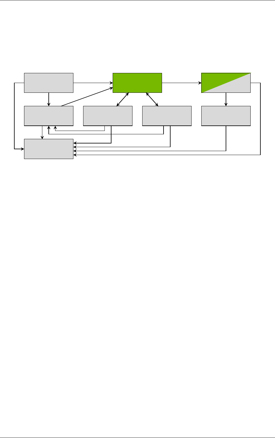
The ray-tracing “pipeline” is based on the interconnected calling structure of the eight
programs and their relationship to the search through the geometric data in the scene, called a
traversal. Figure 2.1 is a diagram of these relationships:
Ray generation
callable
Continuation
Direct callable
Miss Closest-hit Any-hit
IntersectionIntersectionScene traversal
Fig. 2.1 - Relationship of NVIDIA OptiX programs. Green represents fixed functions; gray
represents user programs.
In Figure 2.1, green represents fixed-function, hardware-accelerated operations, while gray
represents user programs. The built-in or user-provided exception program may be called
from any program or scene traversal in case of an exception if exceptions are enabled.
2.2.1 Shader binding table
The shader binding table connects geometric data to programs and their parameters. A record is
a component of the shader binding table that is selected during execution by using offsets
specified when acceleration structures are created and at runtime. A record contains two data
regions, header and data.
Record header
•
Opaque to the application, filled in by optixSbtRecordPackHeader
•
Used by NVIDIA OptiX to identify programmatic behavior. For example, a primitive
would identify the intersection, any-hit, and closest-hit behavior for that primitive in the
header.
Record data
•
Opaque to NVIDIA OptiX
•
User data associated with the primitive or programs referenced in the headers can be
stored here, for example, program parameter values.
2.2.2 Ray payload
The ray payload is used to pass data between optixTrace and the programs invoked during
ray traversal. Payload values are passed to and returned from optixTrace, and follow a
copy-in/copy-out semantic. There is a limited number of payload values, but one or more of
6 NVIDIA OptiX 7.7 ± Programming Guide © 2023 NVIDIA Corporation

2.3 Acceleration structures 2 Basic concepts and denitions
these values can also be a pointer to stack-based local memory, or application-managed
global memory. See
“Payload” (page 115).
2.2.3 Primitive attributes
Attributes are used to pass data from intersection programs to the any-hit and closest-hit
programs. Triangle intersection provides two predefined attributes for the barycentric
coordinates (U,V). User-defined intersections can define a limited number of other attributes
that are specific to those primitives.
2.2.4 Buer
NVIDIA OptiX represents GPU information with a pointer to GPU memory. References to the
term “buffer” in this document refer to this GPU memory pointer and the associated memory
contents. Unlike NVIDIA OptiX 6, the allocation and transfer of buffers is explicitly
controlled by user code.
2.3 Acceleration structures
NVIDIA OptiX acceleration structures are opaque data structures built on the device.
Typically, they are based on the
bounding volume hierarchy
1
model, but implementations and
the data layout of these structures may vary from one GPU architecture to another.
NVIDIA OptiX provides two basic types of acceleration structures:
Geometry acceleration structures
•
Built over primitives (triangles, curves, spheres, or user-defined primitives)
Instance acceleration structures
•
Built over other objects such as acceleration structures (either type) or motion transform
nodes
•
Allow for instancing with a per-instance static transform
2.4 Opacity micromaps
NVIDIA OptiX opacity micromaps are opaque data structures built on the device. An opacity
micromap specifies detailed opacity information for a triangle. See “Opacity micromaps”
(page 41).
2.5 Traversing the scene graph
To determine the intersection of geometric data by a ray, NVIDIA OptiX searches a graph of
nodes composed of acceleration structures and transformations. This search is called a
traversal; the nodes in the graph are called traversable objects or traversables.
The following types of traversable objects exist:
•
An instance acceleration structure
1. https://en.wikipedia.org/wiki/Bounding_volume_hierarchy
© 2023 NVIDIA Corporation NVIDIA OptiX 7.7 ± Programming Guide 7
2 Basic concepts and denitions 2.5 Traversing the scene graph
•
A geometry acceleration structure (as a root for graph with a single geometry
acceleration structure (see
Traversal of a single geometry acceleration structure (page 34))
•
Static transform
•
Matrix motion transform
•
Scaling, rotation, translation (SRT) motion transform
For transformation traversables, the corresponding transformation applies to all descendant
child traversables (the sub graph spanned by the child of the transformation traversable). The
transformation traversables should only be used in case of motion as applying
transformations to geometry is order dependent and motion transformations are time
dependent. Static transformations are available as they cannot be merged with any motion
transformation due to time-dependency, but should be merged with instance transformations
(if desired as the child of an instance) or any other static transformation (i.e., there should be
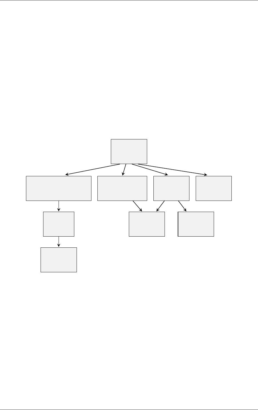
at most one static transformation following a motion transformation). For example, Figure 2.2
combines both types:
motion transform
Scale / rotate / translate
motion transform
Matrix
structure
acceleration
Instance
structure
acceleration
Geometry
structure
acceleration
Instance
transform
Static
structure
acceleration
Geometry
structure
acceleration
Geometry
structure
acceleration
Geometry
Fig. 2.2 - Example graph of traversables for a scene containing static as well as dynamic
motion-transform driven objects
OptiX uses handles as references to traversable objects. These traversable handles are 64-bit
opaque values that are generated from device memory pointers for the graph nodes. The
handles identify the connectivity of these objects. All calls to optixTrace begin at a
traversable handle.
8 NVIDIA OptiX 7.7 ± Programming Guide © 2023 NVIDIA Corporation

2.6 Ray tracing with NVIDIA OptiX 2 Basic concepts and denitions
Note: DXR and VulkanRT use the terms top-level acceleration structure and bottom-level
acceleration structure. A bottom-level acceleration structure is the same as a geometry
acceleration structure; a top-level acceleration structure is similar to an instance
acceleration structure. Traversing against a single geometry acceleration structure,
motion transform nodes, or nested instance acceleration structures (multi-level
instancing) are not supported in DXR or VulkanRT. In NVIDIA OptiX, the terms were
changed due to the additional possible configurations of scene graphs beyond the strict
two-level, top-bottom configurations supported by DXR and VulkanRT. (See
DirectX
Raytracing (DXR) Functional Spec
.
2
)
2.6 Ray tracing with NVIDIA OptiX
A functional ray tracing system is implemented by combining four components as described
in the following steps:
1. Create one or more acceleration structures over one or many geometry meshes and
instances of these meshes in the scene. See
“Acceleration structures” (page 19).
2. Create a pipeline of programs that contains all programs that will be invoked during a
ray tracing launch. See
“Program pipeline creation” (page 61).
3. Create a shader binding table that includes references to these programs and their
parameters and choose a data layout that matches the implicit shader binding table
record selection of the instances and geometries in the acceleration structures. See
“Shader binding table” (page 77).
4. Launch a device-side kernel that will invoke a ray generation program with a multitude
of threads calling optixTrace to begin traversal and the execution of the other
programs. See
“Ray generation launches” (page 91). Device-side functionality is
described in
“Device-side functions” (page 95).
Ray tracing work can be interleaved with other CUDA work to generate data, move data to
and from the device, and move data to other graphics APIs. It is the application’s
responsibility to coordinate all work on the GPU. NVIDIA OptiX does not synchronize with
any other work.
2. https://microsoft.github.io/DirectX-Specs/d3d/Raytracing.html#geometry-and-acceleration-structures
© 2023 NVIDIA Corporation NVIDIA OptiX 7.7 ± Programming Guide 9

2 Basic concepts and denitions 2.6 Ray tracing with NVIDIA OptiX
10 NVIDIA OptiX 7.7 ± Programming Guide © 2023 NVIDIA Corporation

3 Implementation principles
3.1 Error handling
Errors are reported using enumerated return codes. An optional log callback can be
registered with the device context to receive any additional logging information.
Functions that compile can optionally take a string character buffer to report additional
messaging for errors, warnings and resource use.
3.2 Thread safety
Almost all host functions are thread-safe. Exceptions to this rule are identified in the API
documentation. A general requirement for thread-safety is that output buffers and any
temporary or state buffers are unique. For example, you can create more than one
acceleration structure concurrently from the same input geometry, as long as the temporary
and output device memory are disjoint. Temporary and state buffers are always part of the
parameter list if they are needed to execute the method.
3.3 Stateless model
Given the same input, the same output should be generated. GPU state is not held by
NVIDIA OptiX internally.
In NVIDIA OptiX functions, a CUstream is associated with the CUcontext used to create the
OptixDeviceContext. Some API functions take a CUstream as an argument. These functions
incur work on the device and require that the CUcontext associated with the
OptixDeviceContext is the current context when they are called. Applications can expect the
CUcontext to remain the same after invoking NVIDIA OptiX functions.
3.4 Asynchronous execution
Work performed on the device is issued on an application-supplied CUstream using
asynchronous CUDA methods. The host function blocks execution until all work has been
issued on the stream, but does not do any synchronization or blocking on the stream itself.
3.5 Opaque types
The API employs several opaque types, such as OptixModule and OptixPipeline. Such
values should be treated like pointers, insofar as copying these does not create new objects.
3.6 Function table and entry function
The NVIDIA OptiX library uses a function table approach to assist in the introduction of new
features in future releases while maintaining backward compatibility. To that end, it defines a
© 2023 NVIDIA Corporation NVIDIA OptiX 7.7 ± Programming Guide 11

3 Implementation principles 3.6 Function table and entry function
struct OptixFunctionTable that holds pointers to all functions of the host API for a particular
version. The current version is specified in the OPTIX_ABI_VERSION macro definition.
Listing 3.1
struct OptixFunctionTable
{
OptixResult (*optixDeviceContextCreate)(
...
Parameter list details omitted
);
...
Struct members for other host API functions omitted
};
The NVIDIA OptiX driver library exports the symbol optixQueryFunctionTable. This
function is used to obtain pointers to the actual API functions:
Listing 3.2
OptixQueryFunctionTable_t* optixQueryFunctionTable;
...
OS-specic code to load the library and to assign the address of
OptixQueryFunctionTable to optixQueryFunctionTable omitted
OptixFunctionTable optixFunctionTable = {};
OptixResult result = optixQueryFunctionTable(
OPTIX_ABI_VERSION, 0, 0, 0, &optixFunctionTable,
sizeof(OptixFunctionTable));
...
Error check omitted
Note that the three “0 ”arguments in the example above allow for future extensions of the
entry function without changing its signature and are currently unused. A complete example
implementation of this functionality including code specific to the operating system is
provided as source code in optixInit() found in the header file optix_stubs.h.
After a successful call to optixQueryFunctionTable, the function table can be used as
follows, for example, for context creation:
Listing 3.3
CUcontext fromContext = nullptr;
...
fromContext initialization omitted
OptixDeviceContextOptions options = {};
...
options initialization omitted
OptixResult result = optixFunctionTable.optixDeviceContextCreate(
fromContext, &options, &context);
...
Error check omitted
12 NVIDIA OptiX 7.7 ± Programming Guide © 2023 NVIDIA Corporation

3.6 Function table and entry function 3 Implementation principles
Since the explicit call qualifications with the function table instance can be inconvenient,
optional stubs that wrap the addresses in the function table into C functions are provided.
These stubs are made available by including the header file optix_stubs.h. With these stubs
the previous example can be simplified as follows:
Listing 3.4
CUcontext fromContext = nullptr;
...
fromContext initialization omitted
OptixDeviceContextOptions options = {};
...
options initialization omitted
OptixResult result = optixDeviceContextCreate(
fromContext, &options, &context);
...
Error check omitted
Using these stubs is purely optional and applications are free to implement their own solution
to make the addresses in the function table more easily available.
© 2023 NVIDIA Corporation NVIDIA OptiX 7.7 ± Programming Guide 13

3 Implementation principles 3.6 Function table and entry function
14 NVIDIA OptiX 7.7 ± Programming Guide © 2023 NVIDIA Corporation

4 Context
The API functions described in this section are:
optixDeviceContextCreate
optixDeviceContextDestroy
optixDeviceContextGetProperty
optixDeviceContextSetLogCallback
optixDeviceContextSetCacheEnabled
optixDeviceContextSetCacheLocation
optixDeviceContextSetCacheDatabaseSizes
optixDeviceContextGetCacheEnabled
optixDeviceContextGetCacheLocation
optixDeviceContextGetCacheDatabaseSizes
A context is created by optixDeviceContextCreate and is used to manage a single GPU. The
NVIDIA OptiX device context is created by specifying the CUDA context associated with the
device. For convenience, zero can be passed and NVIDIA OptiX will use the current CUDA
context.
Listing 4.1
OptixDeviceContext context = nullptr;
cudaFree(0);
Initialize CUDA for this device on this thread
CUcontext cuCtx = 0;
Zero means take the current context
optixDeviceContextCreate(cuCtx, 0, &context);
Additional creation time options can also be specified with OptixDeviceContextOptions,
including parameters for specifying a callback function, log and data. (See “Sending
messages with a callback function”
(page 16).)
A small set of context properties exist for determining sizes and limits. These are queried
using optixDeviceContextGetProperty. Such properties include maximum trace depth,
maximum traversable graph depth, maximum primitives per build input, and maximum
number of instances per acceleration structure.
The context may retain ownership of any GPU resources necessary to launch the ray tracing
kernels. Some API objects will retain host memory. These are defined with create/destroy
patterns in the API. The application must invoke optixDeviceContextDestroy to clean up
any host or device resources associated with the context. If any other API objects associated
with this context still exist when the context is destroyed, they are also destroyed.
© 2023 NVIDIA Corporation NVIDIA OptiX 7.7 ± Programming Guide 15

4 Context 4.1 Sending messages with a callback function
A context can hold a decryption key. When specified, the context requires user code passed
into the API to be encrypted using the appropriate session key. This minimizes exposure of
the input code to security attacks.
Note: The context decryption feature is available upon request from NVIDIA.
An application may combine any mixture of supported GPUs as long as the data transfer and
synchronization is handled appropriately. Some applications may choose to simplify
multi-GPU handling by restricting the variety of these blends, for example, by mixing only
GPUs of the same streaming multiprocessor version to simplify data sharing.
4.1 Sending messages with a callback function
A log callback and pointer to host memory can also be specified during context creation or
later by using optixDeviceContextSetLogCallback. This callback will be used to
communicate various messages. It must be thread-safe if multiple NVIDIA OptiX functions
are called concurrently.
This callback must be a pointer to a function of the following type:
Listing 4.2
typedef void (*OptixLogCallback)(
unsigned int level,
const char* tag,
const char* message,
void* cbdata);
The log level indicates the severity of the message. The tag is a terse message category
description (for example, SCENE STAT). The message is a null-terminated log message
(without a newline character at the end) and the value of cbdata, the pointer provided when
setting the callback function.
The following log levels are supported:
disable
Disables all messages. The callback function is not called in this case.
fatal
A non-recoverable error. The context, as well as NVIDIA OptiX itself, may no longer be
in a usable state.
error
A recoverable error, for example, when passing invalid call parameters.
warning
Hints that the API might not behave exactly as expected by the application or that it may
perform slower than expected.
print
Status and progress messages.
16 NVIDIA OptiX 7.7 ± Programming Guide © 2023 NVIDIA Corporation

4.2 Compilation caching 4 Context
4.2 Compilation caching
Compilation of input programs will be cached to disk when creating OptixModule,
OptixProgramGroup, and OptixPipeline objects if caching has been enabled. Subsequent
compilation can reuse the cached data to improve the time to create these objects. The cache
can be shared between multiple OptixDeviceContext objects, and NVIDIA OptiX will take
care of ensuring correct multi-threaded access to the cache. If no sharing between
OptixDeviceContext objects is desired, the path to the cache can be set differently for each
OptixDeviceContext. Caching can be disabled entirely by setting the environment variable
OPTIX_CACHE_MAXSIZE to 0. Disabling the cache via the environment variable will not affect
existing cache files or their contents.
The disk cache can be controlled with:
optixDeviceContextSetCacheEnabled(..., int enabled)
When enabled has a value of 1, the disk cache is enabled; a value of 0 disables it. Note
that no in-memory cache is used when caching is disabled.
The cache database is initialized when the device context is created and when enabled
through this function call. If the database cannot be initialized when the device context is
created, caching will be disabled; a message is reported to the log callback if caching is
enabled. In this case, the call to optixDeviceContextCreate does not return an error. To
ensure that cache initialization succeeded on context creation, the status can be queried
using optixDeviceContextGetCacheEnabled. If caching is disabled, the cache can be
reconfigured and then enabled using optixDeviceContextSetCacheEnabled. If the
cache database cannot be initialized with optixDeviceContextSetCacheEnabled, an
error is returned. Garbage collection is performed on the next write to the cache
database, not when the cache is enabled.
optixDeviceContextSetCacheLocation(..., const char* location)
The disk cache is created in the directory specified by location. The value of location
must be a NULL-terminated string. The directory is created if it does not exist.
The cache database is created immediately if the cache is currently enabled. Otherwise
the cache database is created later when the cache is enabled. An error is returned if it is
not possible to create the cache database file at the specified location for any reason (for
example, if the path is invalid or if the directory is not writable) and caching will be
disabled. If the disk cache is located on a network file share, behavior is undefined.
The location of the disk cache can be overridden with the environment variable
OPTIX_CACHE_PATH. This environment variable takes precedence over the value passed
to this function when the disk cache is enabled.
The default location of the cache depends on the operating system:
Operating system Pathname
Windows %LOCALAPPDATA%\NVIDIA\OptixCache
Linux /var/tmp/OptixCache_username, or
/tmp/OptixCache_username if the first choice is not
usable. The underscore and username suffix are omitted
if the username cannot be obtained.
© 2023 NVIDIA Corporation NVIDIA OptiX 7.7 ± Programming Guide 17

4 Context 4.3 Validation mode
optixDeviceContextSetCacheDatabaseSizes(
..., size_t lowWaterMark, size_t highWaterMark)
Parameters lowWaterMark and highWaterMark set the low and high water marks for disk
cache garbage collection. Setting either limit to zero disables garbage collection. Garbage
collection only happens when the cache database is written. It is triggered whenever the
cache data size exceeds the high water mark and proceeding until the size reaches the
low water mark. Garbage collection always frees enough space to allow the insertion of
the new entry within the boundary of the low water mark. An error is returned if either
limit is nonzero and the high water mark is lower than the low water mark. If more than
one device context accesses the same cache database with different high and low water
mark values, the device context uses its values when writing to the cache database.
The high water mark can be overridden with the environment variable
OPTIX_CACHE_MAXSIZE. Setting OPTIX_CACHE_MAXSIZE to 0 will disable the cache.
Negative and non-integer values will be ignored.
The value of OPTIX_CACHE_MAXSIZE takes precedence over the highWaterMark value
passed to this function. The low water mark will be set to half the value of
OPTIX_CACHE_MAXSIZE.
Corresponding get* functions are supplied to retrieve the current value of these cache
properties.
4.3 Validation mode
The NVIDIA OptiX validation mode can help uncover errors which might otherwise go
undetected or which occur only intermittently and are difficult to locate. Validation mode
enables additional tests and settings during application execution. This additional processing
can reduce performance, so it should only be used during debugging or in the final testing
phase of a completed application.
Validation mode is enabled by setting a field in the OptixDeviceContextOptions struct:
Listing 4.3
OptixDeviceContextOptions options = {};
options.validationMode = OPTIX_DEVICE_CONTEXT_VALIDATION_MODE_ALL;
The error OPTIX_ERROR_VALIDATION_FAILURE is signaled if an error is caught when
validation mode is enabled. Function optixLaunch will synchronize after the launch and
report errors, if any.
Among other effects, validation mode implicitly enables all OptiX debug exceptions and
provides an exception program if none is provided. The first non-user exception caught
inside an exception program will therefore be reported and the launch terminated
immediately. This will make exceptions more visible that otherwise might be overlooked.
18 NVIDIA OptiX 7.7 ± Programming Guide © 2023 NVIDIA Corporation

5 Acceleration structures
The API functions described in this section are:
optixAccelComputeMemoryUsage
optixAccelBuild
optixAccelRelocate
optixConvertPointerToTraversableHandle
NVIDIA OptiX provides acceleration structures to optimize the search for the intersection of
rays with the geometric data in the scene. Acceleration structures can contain two types of
data: geometric primitives (a geometry-AS) or instances (an instance-AS). Acceleration
structures are created on the device using a set of functions. These functions enable
overlapping and pipelining of acceleration structure creation, called a build. The functions use
one or more OptixBuildInput structs to specify the geometry plus a set of parameters to
control the build.
Acceleration structures have size limits, listed in
“Limits” (page 93). For an instance
acceleration structure, the number of instances has an upper limit. For a geometry
acceleration structure, the number of geometric primitives is limited, specifically the total
number of primitives in its build inputs, multiplied by the number of motion keys.
The following build input types are supported:
Instance acceleration structures
OPTIX_BUILD_INPUT_TYPE_INSTANCES
OPTIX_BUILD_INPUT_TYPE_INSTANCE_POINTERS
A geometry acceleration structure containing built-in triangles
OPTIX_BUILD_INPUT_TYPE_TRIANGLES
A geometry acceleration structure containing built-in curve primitives
OPTIX_BUILD_INPUT_TYPE_CURVES
A geometry acceleration structure containing built-in spheres
OPTIX_BUILD_INPUT_TYPE_SPHERES
A geometry acceleration structure containing custom primitives
OPTIX_BUILD_INPUT_TYPE_CUSTOM_PRIMITIVES
For geometry-AS builds, each build input can specify a set of triangles, a set of curves, a set of
spheres, or a set of user-defined primitives bounded by specified axis-aligned bounding
boxes. Multiple build inputs can be passed as an array to optixAccelBuild to combine
different meshes into a single acceleration structure. All build inputs for a single build must
agree on the build input type.
© 2023 NVIDIA Corporation NVIDIA OptiX 7.7 ± Programming Guide 19

5 Acceleration structures
Instance acceleration structures have a single build input and specify an array of instances.
Each instance includes a ray transformation and an OptixTraversableHandle that refers to a
geometry-AS, a transform node, or another instance acceleration structure.
To prepare for a build, the required memory sizes are queried by passing an initial set of build
inputs and parameters to optixAccelComputeMemoryUsage. It returns three different sizes:
outputSizeInBytes
Size of the memory region where the resulting acceleration structure is placed. This size
is an upper bound and may be substantially larger than the final acceleration structure.
(See
“Compacting acceleration structures” (page 31).)
tempSizeInBytes
Size of the memory region that is temporarily used during the build.
tempUpdateSizeInBytes
Size of the memory region that is temporarily required to update the acceleration
structure.
Using these sizes, the application allocates memory for the output and temporary memory
buffers on the device. The pointers to these buffers must be aligned to a 128-byte boundary.
These buffers are actively used for the duration of the build. For this reason, they cannot be
shared with other currently active build requests.
Note that optixAccelComputeMemoryUsage does not initiate any activity on the device;
pointers to device memory or contents of input buffers are not required to point to allocated
memory.
The function optixAccelBuild takes the same array of OptixBuildInput structs as
optixAccelComputeMemoryUsage and builds a single acceleration structure from these
inputs. This acceleration structure can contain either geometry or instances, depending on the
inputs to the build.
The build operation is executed on the device in the specified CUDA stream and runs
asynchronously on the device, similar to CUDA kernel launches. The application may choose
to block the host-side thread or synchronize with other CUDA streams by using available
CUDA synchronization functionality such as cudaStreamSynchronize or CUDA events. The
traversable handle returned is computed on the host and is returned from the function
immediately, without waiting for the build to finish. By producing handles at acceleration
time, custom handles can also be generated based on input to the builder.
The acceleration structure constructed by optixAccelBuild does not reference any of the
device buffers referenced in the build inputs. All relevant data is copied from these buffers
into the acceleration output buffer, possibly in a different format.
The application is free to release this memory after the build without invalidating the
acceleration structure. However, instance-AS builds will continue to refer to other
instance-AS and geometry-AS instances and transform nodes.
20 NVIDIA OptiX 7.7 ± Programming Guide © 2023 NVIDIA Corporation

5.1 Primitive build inputs 5 Acceleration structures
The following example uses this sequence to build a single acceleration structure:
Listing 5.1
OptixAccelBuildOptions accelOptions = {};
OptixBuildInput buildInputs[2];
CUdeviceptr tempBuffer, outputBuffer;
size_t tempBufferSizeInBytes, outputBufferSizeInBytes;
memset(accelOptions, 0, sizeof(OptixAccelBuildOptions));
accelOptions.buildFlags = OPTIX_BUILD_FLAG_NONE;
accelOptions.operation = OPTIX_BUILD_OPERATION_BUILD;
accelOptions.motionOptions.numKeys = 0;
A numKeys value of zero species no
motion blur
memset(buildInputs, 0, sizeof(OptixBuildInput) * 2);
Initialize buildInputs
memory to 0
...
Setup bu ild inputs; see below.
OptixAccelBufferSizes bufferSizes = {};
optixAccelComputeMemoryUsage(optixContext, &accelOptions,
buildInputs, 2, &bufferSizes);
void* d_output;
void* d_temp;
cudaMalloc(&d_output, bufferSizes.outputSizeInBytes);
cudaMalloc(&d_temp, bufferSizes.tempSizeInBytes);
OptixTraversableHandle outputHandle = 0;
OptixResult results = optixAccelBuild(optixContext, cuStream,
&accelOptions, buildInputs, 2, d_temp,
bufferSizes.tempSizeInBytes, d_output,
bufferSizes.outputSizeInBytes, &outputHandle, nullptr, 0);
To ensure compatibility with future versions, the OptixBuildInput structure should be
initialized with zeros before populating it with specific build inputs.
5.1 Primitive build inputs
A triangle build input references an array of triangle vertex buffers in device memory, one
buffer per motion key (a single triangle vertex buffer if there is no motion). (See
“Motion
blur” (page 34).) Optionally, triangles can be indexed using an index buffer in device
memory. Various vertex and index formats are supported as input, but may be transformed to
an internal format (potentially of a different size than the input) that is more efficient.
For example:
© 2023 NVIDIA Corporation NVIDIA OptiX 7.7 ± Programming Guide 21

5 Acceleration structures 5.1 Primitive build inputs
Listing 5.2
OptixBuildInputTriangleArray& buildInput =
buildInputs[0].triangleArray;
buildInput.type = OPTIX_BUILD_INPUT_TYPE_TRIANGLES;
buildInput.vertexBuffers = &d_vertexBuffer;
buildInput.numVertices = numVertices;
buildInput.vertexFormat = OPTIX_VERTEX_FORMAT_FLOAT3;
buildInput.vertexStrideInBytes = sizeof(float3);
buildInput.indexBuffer = d_indexBuffer;
buildInput.numIndexTriplets = numTriangles;
buildInput.indexFormat = OPTIX_INDICES_FORMAT_UNSIGNED_INT3;
buildInput.indexStrideInBytes = sizeof(int3);
buildInput.preTransform = 0;
The preTransform is an optional pointer to a 3x4 row-major transform matrix in device
memory. The pointer needs to be aligned to 16 bytes; the matrix contains 12 floats. If specified,
the transformation is applied to all vertices at build time with no runtime traversal overhead.
A curves build input or a spheres build input is similar to a triangle build input; see
“Curve
build inputs” (page 24), “Sphere build inputs” (page 25).
The acceleration structure build input for custom primitives uses the type
OptixBuildInputCustomPrimitiveArray. Each custom primitive is represented by an
axis-aligned bounding box (AABB), which is a rectangular solid defined by ranges of x, y, and z
values, and which must completely enclose the primitive. The memory layout of an AABB is
defined in the struct OptixAabb. The AABBs are organized in an array of buffers in device
memory, with one buffer per motion key. The precise shape of each custom primitive will be
depend on the intersection program in its SBT record.
Listing 5.3
OptixBuildInputCustomPrimitiveArray& buildInput =
buildInputs[0].customPrimitiveArray;
buildInput.type = OPTIX_BUILD_INPUT_TYPE_CUSTOM_PRIMITIVES;
buildInput.aabbBuffers = d_aabbBuffer;
buildInput.numPrimitives = numPrimitives;
The optixAccelBuild function accepts multiple build inputs per call, but they must be all
triangle inputs, all curve inputs, all sphere inputs, or all AABB inputs. Mixing build input
types in a single geometry-AS is not allowed.
Each build input maps to one or more consecutive records in the shader binding table (SBT),
which controls program dispatch. (See
“Shader binding table” (page 77).) If multiple records
in the SBT are required, the application needs to provide a device buffer with per-primitive
SBT record indices for that build input. If only a single SBT record is requested, all primitives
reference this same unique SBT record. Note that there is a limit to the number of referenced
SBT records per geometry-AS. (Limits are discussed in
“Limits” (page 93).)
22 NVIDIA OptiX 7.7 ± Programming Guide © 2023 NVIDIA Corporation

5.1 Primitive build inputs 5 Acceleration structures
For example:
Listing 5.4
buildInput.numSbtRecords = 2;
buildInput.sbtIndexOffsetBuffer =
d_sbtIndexOffsetBuffer;
Values must be in range [0,1] for two SBT
records
buildInput.sbtIndexOffsetSizeInBytes = sizeof(int);
1-4 byte unsigned
integer osets allowed
buildInput.sbtIndexOffsetStrideInBytes = sizeof(int);
Each build input also specifies an array of OptixGeometryFlags, one for each SBT record.
The flags for one record apply to all primitives mapped to this SBT record.
For example:
Listing 5.5
unsigned int flagsPerSBTRecord[2];
flagsPerSBTRecord[0] = OPTIX_GEOMETRY_FLAG_NONE;
flagsPerSBTRecord[1] = OPTIX_GEOMETRY_FLAG_DISABLE_ANYHIT;
...
buildInput.flags = flagsPerSBTRecord;
The following flags are supported:
OPTIX_GEOMETRY_FLAG_NONE
Applies the default behavior when calling the any-hit program, possibly multiple times,
allowing the acceleration-structure builder to apply all optimizations.
OPTIX_GEOMETRY_FLAG_REQUIRE_SINGLE_ANYHIT_CALL
Disables some optimizations specific to acceleration-structure builders. By default,
traversal may call the any-hit program more than once for each intersected primitive.
Setting the flag ensures that the any-hit program is called only once for a hit with a
primitive. However, setting this flag may change traversal performance. The usage of
this flag may be required for correctness of some rendering algorithms; for example, in
cases where opacity or transparency information is accumulated in an any-hit program.
OPTIX_GEOMETRY_FLAG_DISABLE_ANYHIT
Indicates that traversal should not call the any-hit program for this primitive even if the
corresponding SBT record contains an any-hit program. Setting this flag usually
improves performance even if no any-hit program is present in the SBT.
Primitives inside a build input are indexed starting from zero. This primitive index is
accessible inside the intersection, any-hit, and closest-hit programs. If the application chooses
to offset this index for all primitives in a build input, there is no overhead at runtime. This can
be particularly useful when data for consecutive build inputs is stored consecutively in
device memory. The primitiveIndexOffset value is only used when reporting the
intersection primitive.
© 2023 NVIDIA Corporation NVIDIA OptiX 7.7 ± Programming Guide 23

5 Acceleration structures 5.2 Curve build inputs
For example:
Listing 5.6
buildInput[0].aabbBuffers = d_aabbBuffer;
buildInput[0].numPrimitives = ...;
buildInput[0].primitiveIndexOffset = 0;
buildInput[1].aabbBuffers = d_aabbBuffer +
buildInput[0].numPrimitives * sizeof(float) * 6;
buildInput[1].numPrimitives = ...;
buildInput[1].primitiveIndexOffset = buildInput[0].numPrimitives;
5.2 Curve build inputs
In addition to triangles and custom primitives, NVIDIA OptiX supports curves and spheres
as geometric primitives. Curves are used to represent long thin strands, such as for hair, fur,
and carpet fibers. Another variant of curves, ribbons (oriented curves), can be used for blades
of grass and similar applications. Scenes may contain thousands or millions of curves, and
they will often be no wider than a couple of pixels in the final image.
Each curve is a swept surface defined by a three-dimensional series of vertices, called control
points, and a possibly varying radius. The NVIDIA OptiX API provides curves with these
characteristics:
•
Curve geometry is defined by a cubic uniform B-spline curve, a quadratic uniform
B-spline curve, a Catmull-Rom spline curve, a Bézier curve, or a series of linear
segments.
•
The cross-section of the curve primitive is a circle.
•
For quadratic B-spline curves the cross-section can also be a straight line segment which
allows to represent flat oriented curves, called ribbons. These are ruled surfaces which
are formed by sweeping a moving straight line along the curve axis.
•
A radius is specified at each control point. The radius is interpolated along the curve
using the same spline basis as position.
•
For ribbons, normals can be specified but are not required.
•
Linear curves have spherical end caps, with spherical “elbows” for smooth joints
between segments. By default, the ends of cubic and quadratic splines are open and do
not have end caps. Flat end caps for cubic and quadratic splines can be enabled by
setting OptixBuildInputCurveArray::endcapFlags and
OptixBuiltinISOptions::curveEndcapFlags to OPTIX_CURVE_ENDCAP_ON.
Spline curves are composed of a series of polynomial segments. Each segment is defined by
two, three, or four control points, depending on the curve type:
24 NVIDIA OptiX 7.7 ± Programming Guide © 2023 NVIDIA Corporation

5.3 Sphere build inputs 5 Acceleration structures
Curve type Control points per segment
Piecewise linear 2
Quadratic 3
Cubic 4
Catmull-Rom 4
Bézier 4
NVIDIA OptiX considers each polynomial segment to be a primitive, with its own primitive
ID.
A curve build input (OptixBuildInputCurveArray) references an array of vertex buffers in
device memory, one buffer per motion key (a single vertex buffer if there is no motion). (See
“Motion blur” (page 34).) Parallel to this, there is an array of radius buffers in device memory,
one buffer per motion key, providing a radius value at each control vertex at each motion key.
There is also a (required) index buffer in device memory. Ribbons can also reference optional
normal buffers that are parallel to the vertex buffers.
The B-spline control points of each curve strand will appear sequentially in the vertex buffer.
The index array contains one index per segment, namely, the index of the segment’s first
control point. For example, a cubic curve with three segments will have six vertices. The
index array might contain {10, 11, 12}, in which case the 3 segments will have control
points: {v[10], v[11], v[12], v[13]}, {v[11], v[12], v[13], v[14]} and
{v[12], v[13], v[14], v[15]}.
The vertex buffers for ribbons store quadratic B-spline control points whereas the normal
buffers contain the normals at borders of the ribbon segments. A ribbon strand with three
segments will store five control points. If normals are specified, four normals will be required
for three segments. They are linearly interpolated along the curve segments. For example, the
ribbon strand might have indices {0, 1, 2}. In this case, the control points of the segments
would be {v[0], v[1], v[2]}, {v[1], v[2], v[3]} and {v[2], v[3], v[4]}, the
normals {n[0], n[1]}, {n[1], n[2]} and {n[2], n[3]}. The segment with index i will
use control points {v[i], v[i+1], v[i+2]} and normals {n[i], n[i+1]}. Note that there
is one more control point than normals in the ribbon strand. Since the indices are used for
addressing both vertices and normals, the normals need to be padded with an unused vector
at the end of the strand.
End caps appear at the ends of strands. NVIDIA OptiX detects the strands by checking the
overlap of segment control points. Within a B-spline strand, adjacent segments overlap all but
one of their control points. In other words, unless indexArray[N+1] is equal to
indexArray[N]+1, segment N is the end of one strand and segment N+1 is the beginning of
another.
See also
“Differences between curves, spheres, and triangles” (page 85) .
5.3 Sphere build inputs
Similar to curves, NVIDIA OptiX supports spheres as geometric primitives. Spheres can be
used in different applications to represent, for example, molecules, spray, or smoke.
Each sphere is defined by a three-dimensional center point and a radius.
© 2023 NVIDIA Corporation NVIDIA OptiX 7.7 ± Programming Guide 25

5 Acceleration structures 5.4 Instance build inputs
A sphere build input (OptixBuildInputSphereArray) references an array of vertex buffers in
device memory storing the center points, one buffer per motion key (a single vertex buffer if
there is no motion). (See “Motion blur” (page 34).) Parallel to this, there is an array of radius
buffers in device memory, one buffer per motion key, providing a radius value at each vertex
at each motion key. If all spheres have the same radius per motion key, a single radius per
radius buffer is sufficient if the singleRadius flag is set.
See also
“Differences between curves, spheres, and triangles” (page 85) .
5.4 Instance build inputs
An instance build input specifies a buffer of OptixInstance structs in device memory. These
structs can be specified as an array of consecutive structs or an array of pointers to those
structs. Each instance description references:
•
A child traversable handle
•
A static 3x4 row-major object-to-world matrix transform
•
A user ID
•
An SBT offset
•
A visibility mask
•
Instance flags
Unlike the triangle and AABB inputs, optixAccelBuild only accepts a single instance build
input per build call. There are upper limits to the possible number of instances (the size of the
buffer of the OptixInstance structs), the SBT offset, the visibility mask, as well as the user
ID. (These limits are discussed in
“Limits” (page 93).)
An example of this sequence:
Listing 5.7
OptixInstance instance = {};
float transform[12] = {1,0,0,3,0,1,0,0,0,0,1,0};
memcpy(instance.transform, transform, sizeof(float)*12);
instance.instanceId = 0;
instance.visibilityMask = 255;
instance.sbtOffset = 0;
instance.flags = OPTIX_INSTANCE_FLAG_NONE;
instance.traversableHandle = gasTraversable;
void* d_instance;
cudaMalloc(&d_instance, sizeof(OptixInstance));
cudaMemcpy(d_instance, &instance,
sizeof(OptixInstance),
cudaMemcpyHostToDevice);
OptixBuildInputInstanceArray* buildInput =
&buildInputs[0].instanceArray;
buildInput->type = OPTIX_BUILD_INPUT_TYPE_INSTANCES;
26 NVIDIA OptiX 7.7 ± Programming Guide © 2023 NVIDIA Corporation

5.5 Build ags 5 Acceleration structures
buildInput->instances = d_instance;
buildInput->numInstances = 1;
The OPTIX_BUILD_INPUT_TYPE_INSTANCE_POINTERS build input is a variation on the
OPTIX_BUILD_INPUT_TYPE_INSTANCES build input where instanceDescs references a device
memory array of pointers to OptixInstance data structures in device memory.
Instance flags are applied to primitives encountered while traversing the geometry-AS
connected to an instance. The flags override any instance flags set during the traversal of
parent instance-ASs.
OPTIX_INSTANCE_FLAG_DISABLE_TRIANGLE_FACE_CULLING
Disables face culling for triangles. Overrides any culling ray flag passed to optixTrace.
OPTIX_INSTANCE_FLAG_FLIP_TRIANGLE_FACING
Flips the triangle orientation during intersection. Also affects any culling of front and
back faces.
OPTIX_INSTANCE_FLAG_DISABLE_ANYHIT
Disables any-hit calls for primitive intersections. Can be overridden by ray flags.
OPTIX_INSTANCE_FLAG_ENFORCE_ANYHIT
Forces any-hit calls for primitive intersections. Can be overridden by ray flags.
The visibility mask is combined with the ray mask to determine visibility for this instance. If
the condition rayMask & instance.mask == 0 is true, the instance is culled. The visibility
flags may be interpreted as assigning rays and instances to one of eight groups. Instances are
traversed only when the instance and ray have at least one group in common. (See
“Trace”
(page 97).)
The sbtOffset is an offset into the SBT for hit groups (intersection, any-hit, closest-hit)
specified with the hitgroupRecordBase parameter of OptixShaderBindingTable. It is used
as a simple additive offset into the SBT to select the hit group programs run in case of an
intersection of a primitive part of this instance. See
“Acceleration structures” (page 7) for
more detail. If the child of the instance is a transform object — an OptixStaticTransform,
OptixMatrixMotionTransform, or OptixSRTMotionTransform traversable object instead of
a geometry-AS — the instance’s sbtOffset value still applies when hitting a primitive of the
geometry-AS at the end of the chain of transforms. The maximal supported SBT offset can be
queried using optixDeviceContextGetProperty with
OPTIX_DEVICE_PROPERTY_LIMIT_MAX_SBT_OFFSET. In a traversable graph with multiple
levels of instance acceleration structure (IAS) objects the offsets are added together. That is,
the offset at a GAS is the sum of the offsets of all ancestor instances in the traversable graph.
The maximal supported summed SBT offset is equal to the maximum SBT offset for a single
instance.
5.5 Build ags
An acceleration structure build can be controlled using the values of the OptixBuildFlags
enum. To enable random vertex access on an acceleration structure, use
OPTIX_BUILD_FLAG_ALLOW_RANDOM_VERTEX_ACCESS. (See
“Vertex random access”
(page 103).) To steer trade-offs between build performance, runtime traversal performance
and acceleration structure memory usage, use OPTIX_BUILD_FLAG_PREFER_FAST_TRACE and
© 2023 NVIDIA Corporation NVIDIA OptiX 7.7 ± Programming Guide 27

5 Acceleration structures 5.6 Dynamic updates
OPTIX_BUILD_FLAG_PREFER_FAST_BUILD. For curve primitives in particular, these flags
control splitting; see
“Splitting curve segments” (page 86).
The flags OPTIX_BUILD_FLAG_PREFER_FAST_TRACE and
OPTIX_BUILD_FLAG_PREFER_FAST_BUILD are mutually exclusive. To combine multiple flags
that are not mutually exclusive, use the logical “or” operator.
5.6 Dynamic updates
Building an acceleration structure can be computationally costly. Applications may choose to
update an existing acceleration structure using modified vertex data or bounding boxes.
Updating an existing acceleration structure is generally much faster than rebuilding.
However, the quality of the acceleration structure may degrade if the data changes too much
with an update, for example, through explosions or other chaotic transitions — even if for
only parts of the mesh. The degraded acceleration structure may result in slower traversal
performance as compared to an acceleration structure built from scratch from the modified
input data.
To allow for future updates of an acceleration structure, set
OPTIX_BUILD_FLAG_ALLOW_UPDATE in the build flags when building the acceleration
structure initially.
For example:
Listing 5.8
accelOptions.buildFlags = OPTIX_BUILD_FLAG_ALLOW_UPDATE;
accelOptions.operation = OPTIX_BUILD_OPERATION_BUILD;
To update the previously built acceleration structure, set the operation to
OPTIX_BUILD_OPERATION_UPDATE and then call optixAccelBuild on the same output data.
All other options are required to be identical to the original build. The update is done in-place
on the output data.
For example:
Listing 5.9
accelOptions.buildFlags = OPTIX_BUILD_FLAG_ALLOW_UPDATE;
accelOptions.operation = OPTIX_BUILD_OPERATION_UPDATE;
void* d_tempUpdate;
cudaMalloc(&d_tempUpdate, bufferSizes.tempUpdateSizeInBytes);
optixAccelBuild(optixContext, cuStream, &accelOptions,
buildInputs, 2, d_tempUpdate,
bufferSizes.tempUpdateSizeInBytes, d_output,
bufferSizes.outputSizeInBytes, &outputHandle, nullptr, 0);
Updating an acceleration structure usually requires a different amount of temporary memory
than the original build.
28 NVIDIA OptiX 7.7 ± Programming Guide © 2023 NVIDIA Corporation

5.7 Relocation 5 Acceleration structures
When updating an existing acceleration structure, only the device pointers and/or their
buffer content may be changed. You cannot change the number of build inputs, the build
input types, build flags, traversable handles for instances (for an instance-AS), or the number
of vertices, indices, AABBs, instances, SBT records or motion keys. Changes to any of these
things may result in undefined behavior, including GPU faults.
Note, however, that in the following two cases it is more efficient to re-build the geometry-AS
and/or the instance-AS, or to use the respective masking and flags:
•
When using indices, changing the connectivity or, in general, using shuffled vertex
positions will work, but the quality of the acceleration structure will likely degrade
substantially.
•
During an animation operation, geometry that should be invisible to the camera should
not be “removed” from the scene, either by moving it very far away or by converting it
into a degenerate form. Such changes to the geometry will also degrade the acceleration
structure.
Setting the acceleration structure flag OPTIX_BUILD_FLAG_ALLOW_UPDATE may also degrade
the performance of the acceleration structure when processing curve primitives.
Updating an acceleration structure requires that any other acceleration structure that is using
this acceleration structure as a child directly or indirectly also needs to be updated or rebuild.
5.7 Relocation
Geometry acceleration structures can be copied and moved, however they may not be used
until optixAccelRelocate has been called to update the copied acceleration structure and
generate the new traversable handle. Any acceleration structure may be relocated, including
compacted acceleration structures.
The copy does not need to be on the original device. This enables the copying of acceleration
structure data to compatible devices without rebuilding the acceleration structure.
To relocate an acceleration structure, an OptixRelocationInfo object is filled using
optixAccelGetRelocationInfo and the traversable handle of the source acceleration
structure. This object can then be used to determine if relocation to a device (as specified with
an OptixDeviceContext) is possible. This is done using
optixCheckRelocationCompatibility. If the target device is compatible, the source
acceleration structure may be copied to that device with a subsequent call of
optixAccelRelocate.
The traversables referenced by an IAS and the OMMs referenced by a triangle GAS may
themselves require relocation. The arguments relocateInputs and numRelocateInputs to
optixAccelRelocate should be used to specify the relocated traversables and OMMs. After
relocation, the relocated acceleration structure will reference these relocated traversables and
OMMs instead of their sources. The number of relocate inputs numRelocateInputs must
match the number of build inputs numBuildInputs used to build the source acceleration
structure. Relocate inputs correspond with build inputs used to build the source acceleration
structure and should appear in the same order (see optixAccelBuild). relocateInputs and
numRelocateInputs may be zero, preserving any references to traversables and OMMs from
the source acceleration structure. An OptixRelocateInputInstanceArray specifies a device
buffer OptixRelocateInputInstanceArray::traversableHandles of handles to relocated
traversables, one per instance. OptixRelocateInputInstanceArray::traversableHandles
© 2023 NVIDIA Corporation NVIDIA OptiX 7.7 ± Programming Guide 29

5 Acceleration structures 5.7 Relocation
may be zero, preserving any references to traversables and OMMs from the source input.
Note that the geometric bounds of the acceleration structure are not updated, so
OptixRelocateInputInstanceArray::traversableHandles should correspond to
relocated source traversables. An OptixRelocateInputTriangleArray may specify a
relocated OMM OptixRelocateInputTriangleArray::opacityMicromap.
OptixRelocateInputTriangleArray::opacityMicromap may be zero, preserving any
references to the OMM from the source input.
OptixRelocateInputTriangleArray::numSbtRecords must equal the corresponding value
OptixBuildInputTriangleArray::numSbtRecords.
The following example relocates the geometry and instance acceleration structure to new
CUDA allocations on the same device:
Listing 5.10
OptixRelocationInfo gasInfo = {};
optixAccelGetRelocationInfo(context, gasHandle, &gasInfo);
int compatible = 0;
optixCheckRelocationCompatibility(
context, &gasInfo, &compatible);
if (compatible != 1) {
fprintf(stderr,
"Device isn’t compatible for relocation "
"of geometry acceleration structures.");
exit(2);
}
This is unnecessary
because the copy
operation’s source
and destination are
on the same device,
but is here to
illustrate the API.
// Copy and relocate the geometry acceleration structure
CUdeviceptr d_relocatedGas = 0;
cudaMalloc((void**)&d_relocatedGas,
gasBufferSizes.outputSizeInBytes);
cudaMemcpy((void*)d_relocatedGas, (void*)d_gasOutputBuffer,
gasBufferSizes.outputSizeInBytes,
cudaMemcpyDeviceToDevice);
OptixTraversableHandle relocatedGasHandle = 0;
optixAccelRelocate(
context, 0,
&gasInfo,
0, 0,
d_relocatedGas,
gasBufferSizes.outputSizeInBytes,
&relocatedGasHandle);
// Copy and relocate the instance acceleration structure
CUdeviceptr d_relocatedIas = 0;
cudaMalloc((void**)&d_relocatedIas,
iasBufferSizes.outputSizeInBytes);
cudaMemcpy((void*)d_relocatedIas, (void*)d_iasOutputBuffer,
iasBufferSizes.outputSizeInBytes,
30 NVIDIA OptiX 7.7 ± Programming Guide © 2023 NVIDIA Corporation

5.8 Compacting acceleration structures 5 Acceleration structures
cudaMemcpyDeviceToDevice);
OptixRelocationInfo iasInfo = {};
optixAccelGetRelocationInfo(
context, iasHandle, &iasInfo);
OptixTraversableHandle relocatedIasHandle = 0;
std::vector<OptixTraversableHandle>
instanceHandles(g_instances.size());
CUdeviceptr d_instanceTravHandles = 0;
cudaMalloc(
(void**)&d_instanceTravHandles,
sizeof(OptixTraversableHandle) * instanceHandles.size());
for (unsigned int i = 0; i < g_instances.size(); ++i)
instanceHandles[i] = relocatedGasHandle;
cudaMemcpy((void*)d_instanceTravHandles, instanceHandles.data(),
sizeof(OptixTraversableHandle) * instanceHandles.size(),
cudaMemcpyHostToDevice);
OptixRelocateInput relocateInput = {};
relocateInput.type = OPTIX_BUILD_INPUT_TYPE_INSTANCES;
relocateInput.instanceArray.numInstances = instanceHandles.size();
relocateInput.instanceArray.traversableHandles = d_instanceTravHandles;
optixAccelRelocate(
context, 0,
&iasInfo,
&relocateInput, 1,
d_relocatedIas,
iasBufferSizes.outputSizeInBytes,
&relocatedIasHandle);
5.8 Compacting acceleration structures
A post-process can compact an acceleration structure after construction. This process can
significantly reduce memory usage, but it requires an additional pass. The build and compact
operations are best performed in batches to ensure that device synchronization does not
degrade performance. The compacted size depends on the acceleration structure type and its
properties and on the device architecture.
To compact the acceleration structure as a post-process, do the following:
1. Build flag OPTIX_BUILD_FLAG_ALLOW_COMPACTION must be set in the
OptixAccelBuildOptions as passed to optixAccelBuild.
2. The emit property OPTIX_PROPERTY_TYPE_COMPACTED_SIZE must be set in the
OptixAccelEmitDesc as passed to optixAccelBuild. This property is generated on the
device and it must be copied back to the host if it is required for allocating the new
© 2023 NVIDIA Corporation NVIDIA OptiX 7.7 ± Programming Guide 31

5 Acceleration structures 5.8 Compacting acceleration structures
output buffer. The application may then choose to compact the acceleration structure
using optixAccelCompact.
3. The optixAccelCompact call should be guarded by an
if (compactedSize < outputSize) (or similar) to avoid the compacting pass in cases
where it is not beneficial. Note that this check requires a copy of the compacted size (as
queried by optixAccelBuild) from the device memory to host memory.
Just like an uncompacted acceleration structure, it is possible to traverse, update, or relocate a
compacted acceleration structure.
For example:
Listing 5.11
size_t *d_compactedSize;
OptixAccelEmitDesc property = {};
property.type = OPTIX_PROPERTY_TYPE_COMPACTED_SIZE;
property.result = d_compactedSize;
OptixTraversableHandle accelHandle = 0;
OptixTraversableHandle compactedAccelHandle = 0;
accelOptions.buildFlags = OPTIX_BUILD_FLAG_ALLOW_COMPACTION;
optixAccelBuild(optixContext, cuStream, &accelOptions,
buildInputs, 2, d_tempUpdate, bufferSizes.tempSizeInBytes,
d_output, bufferSizes.outputSizeInBytes, &accelHandle,
&property, 1);
size_t compactedSize;
cudaMemcpy(&compactedSize, d_compactedSize,
sizeof(size_t),
cudaMemcpyDeviceToHost);
void *d_compactedOutputBuffer;
cudaMalloc(&d_compactedOutputBuffer, compactedSize);
if (compactedSize < bufferSizes.outputSizeInBytes) {
optixAccelCompact(
optixContext, cuStream,
accelHandle,
d_compactedOutputBuffer, compactedSize,
&compactedAccelHandle);
}
A compacted acceleration structure does not reference the uncompacted input data. The
application is free to reuse the memory of the uncompacted acceleration structure without
invalidating the compacted acceleration structure. However, the memory for the compacted
acceleration structure must not overlap memory of the uncompacted acceleration structure as
the compaction operation does not work in-place.
32 NVIDIA OptiX 7.7 ± Programming Guide © 2023 NVIDIA Corporation

5.9 Traversable objects 5 Acceleration structures
A compacted acceleration structure supports dynamic updates only if the uncompacted
source acceleration structure was built with the OPTIX_BUILD_FLAG_ALLOW_UPDATE build
flag. (See “Dynamic updates” (page 28).) The amount of temporary memory required for a
dynamic update is the same for the uncompacted acceleration structure and compacted
acceleration structure. Note that using the following build flags will lead to less memory
savings when enabling the compacting post-process:
•
OPTIX_BUILD_FLAG_ALLOW_UPDATE
•
OPTIX_BUILD_FLAG_PREFER_FAST_BUILD
5.9 Traversable objects
The instances in an instance-AS may reference transform traversables, as well as
geometry-ASs. Transform traversables are fully managed by the application. The application
needs to create these traversables manually in device memory in a specific form. The function
optixConvertPointerToTraversableHandle converts a raw pointer into a traversable
handle of the specified type. The traversable handle can then be used to link traversables
together.
In device memory, all traversable objects need to be 64-byte aligned. Note that moving a
traversable to another location in memory invalidates the traversable handle. The application
is responsible for constructing a new traversable handle and updating any other traversables
referencing the invalidated traversable handle.
The traversable handle is considered opaque and the application should not rely on any
particular mapping of a pointer to the traversable handle.
For example:
Listing 5.12
OptixMatrixMotionTransform transform = {};
...
Setup motion transform
cudaMemcpy(d_transform, &transform,
sizeof(OptixMatrixMotionTransform),
cudaMemcpyHostToDevice);
OptixTraversableHandle transformHandle = 0;
optixConvertPointerToTraversableHandle(
optixContext, d_transform,
OPTIX_TRAVERSABLE_TYPE_MATRIX_MOTION_TRANSFORM,
&transformHandle);
OptixInstance instance = {};
instance.traversableHandle = transformHandle;
...
Setup instance description
© 2023 NVIDIA Corporation NVIDIA OptiX 7.7 ± Programming Guide 33

5 Acceleration structures 5.10 Motion blur
5.9.1 Traversal of a single geometry acceleration structure
The traversable handle passed to optixTrace can be a traversable handle created from a
geometry-AS. This can be useful for scenes where single geometry-AS objects represent the
root of the scene graph.
If the modules and pipeline only need to support single geometry-AS traversables, it is
beneficial to change the OptixPipelineCompileOptions::traversableGraphFlags from
OPTIX_TRAVERSABLE_GRAPH_FLAG_ALLOW_ANY to
OPTIX_TRAVERSABLE_GRAPH_FLAG_ALLOW_SINGLE_GAS.
This signals to NVIDIA OptiX that no other traversable types require support during
traversal.
5.10 Motion blur
Motion support in OptiX targets the rendering of images with motion blur using a stochastic
sampling of time. OptiX supports two types of motion as part of the scene: transform motion
and vertex motion, often called deformation motion. When setting up the scene traversal
graph and building the acceleration structures, motion options can be specified per
acceleration structure as well as per motion transform traversable. At run time, a time
parameter is passed to the trace call to perform the intersection of a ray against the scene at
the selected point in time.
The general design of the motion feature in OptiX tries to strike a balance between providing
many parameters to offer a high degree of freedom combined with a simple mapping of scene
descriptions to these parameters but also delivering high traversal performance at the same
time. As such OptiX supports the following key features:
•
Vertex and transformation motion
•
Matrix as well as SRT (scale rotation translation) transformations
•
Arbitrary time ranges (ranges not limited to [0,1]) and flags to specify behavior outside
the time range
•
Arbitrary concatenations of transformations (for example, a matrix transformation on
top of a SRT transformation)
•
Per-ray timestamps
Scene descriptions with motion need to map easily to traversable objects and their motion
options as offered by OptiX. As such, the idea is that the motion options are directly derived
by the scene description, delivering high traversal performance without the need for any
performance-driven adjustments. However, due to the complexity of the subject, there are a
few exceptions that are discussed in this section.
This section details the usage of the motion options on the different traversable types and
how to map scene options best to avoid potential performance pitfalls.
5.10.1 Basics
Motion is supported by OptixMatrixMotionTransform, OptixSRTMotionTransform and
acceleration structure traversables. The general motion characteristics are specified per
traversable as motion options: the number of motion keys, flags, and the beginning and
ending motion times corresponding to the first and last key. The remaining motion keys are
34 NVIDIA OptiX 7.7 ± Programming Guide © 2023 NVIDIA Corporation

5.10 Motion blur 5 Acceleration structures
evenly spaced between the beginning and ending times. The motion keys are the data at
specific points in time and the data is interpolated in between neighboring keys. The motion
options are specified in the OptixMotionOptions struct.
The motion options are always specified per traversable (acceleration structure or motion
transform). There is no dependency between the motion options of traversables; given an
instance referencing a geometry acceleration structure with motion, it is not required to build
an instance acceleration structure with motion. The same goes for motion transforms. Even if
an instance references a motion transform as child traversable, the instance acceleration
structure itself may or may not have motion.
Motion transforms must specify at least two motion keys with the motion beginning time
strictly smaller than the ending time. Acceleration structures, however, also accept
OptixAccelBuildOptions with field OptixMotionOptions set to zero. This effectively
disables motion for the acceleration structure and ignores the motion beginning and ending
times, along with the motion flags.
OptiX also supports static transform traversables in addition to the static transform of an
instance. Static transforms are intended for the case of motion transforms in the scene.
Without any motion transforms (OptixMatrixMotionTransform or
OptixSRTMotionTransform) in the traversable graph, any static transformation should be
baked into the instance transform. However, if there is a motion transform, it may be required
to apply a static transformation on a traversable (for example, on a geometry-AS) first before
applying the motion transform. For example, a motion transform may be specified in world
coordinates, but the geometry it applies to needs to be placed into the scene first
(object-to-world transformation, which is usually done using the instance transform). In this
case, a static transform pointing at the geometry acceleration structure can be used for the
object-to-world transformation and the instance transform pointing to the motion transform
has an identity matrix as transformation.
Motion boundary conditions are specified by using flags. By default, the behavior for any
time outside the time range, is as if time was clamped to the range, meaning it appears static
and visible. Alternatively, to remove the traversable before the beginning time, set
OPTIX_MOTION_FLAG_START_VANISH; to remove it after the ending time, set
OPTIX_MOTION_FLAG_END_VANISH.
For example:
Listing 5.13
OptixMotionOptions motionOptions = {};
motionOptions.numKeys = 3;
motionOptions.timeBegin = -1f;
motionOptions.timeEnd = 1.5f;
motionOptions.flags = OPTIX_MOTION_FLAG_NONE;
OptiX offers two types of motion transforms, SRTs (scale-rotation-translation) as well as 3x4
affine matrices, each specifying one transform (SRT or matrix) per motion key. The
transformations are always specified as object-to-world transformation just like the instance
transformation. During traversal OptiX performs a per-component linear interpolation of the
two nearest keys. The rotation component (expressed as a quaternion) of the SRT is an
exception, OptiX ensures that the interpolated quaternion of two SRTs is of unit length by
© 2023 NVIDIA Corporation NVIDIA OptiX 7.7 ± Programming Guide 35

5 Acceleration structures 5.10 Motion blur
using nlerp interpolation for performance reasons. This results in a smooth, scale-preserving
rotation in Cartesian space though with non-constant velocity.
For vertex motion, OptiX applies a linear interpolation between the vertex data that are
provided by the application. If intersection programs are used and AABBs are supplied for
the custom primitives, the AABBs are also linearly interpolated for intersection. The AABBs
at the motion keys must therefore be big enough to contain any motion path of the
underlying custom primitive.
There are several device-side functions that take a time parameter such as optixTrace and
respect the motion options as set at the traversables. The result of these device-side functions
is always that of the specified point in time, e.g, the intersection of the ray with the scene at
the selected point in time. Device-side functions are discussed in detail in
“Device-side
functions”
(page 95).
5.10.2 Motion geometry acceleration structure
Use optixAccelBuild to build a motion acceleration structure. The motion options are part
of the build options (OptixAccelBuildOptions) and apply to all build inputs. Build inputs
must specify primitive vertex buffers (for OptixBuildInputTriangleArray,
OptixBuildInputCurveArray, and OptixBuildInputSphereArray), radius buffers (for
OptixBuildInputCurveArray and OptixBuildInputSphereArray), and AABB buffers (for
OptixBuildInputCustomPrimitiveArray and OptixBuildInputInstanceArray) for all
motion keys. These are interpolated during traversal to obtain the continuous motion vertices
and AABBs between the begin and end time.
For example:
Listing 5.14
CUdeviceptr d_motionVertexBuffers[3];
OptixBuildInputTriangleArray buildInput = {};
buildInput.vertexBuffers = d_motionVertexBuffers;
buildInput.numVertices = numVertices;
The motion options are typically defined by the mesh data which should directly map to the
motion options on the geometry acceleration structure. For example, if a triangle mesh has
three per-vertex motion values, the geometry acceleration structure needs to have three
motion keys. Just as for non-motion meshes, it is possible to combine meshes within a single
geometry acceleration structure to potentially increase traversal performance (this is generally
recommended if there is only a single instance of each mesh and the meshes overlap or are
close together). However, these meshes need to share the same motion options (as they are
specified per geometry acceleration structure). The usual trade-offs apply in case meshes need
to be updated from one frame to another as in an interactive application. The entire geometry
acceleration structure needs to be rebuilt or refitted if the vertices of at least one mesh change.
It is possible to use a custom intersection program to decouple the actual vertex data and the
motion options of the geometry acceleration structure. Intersection programs allow any kind
of intersection routine. For example, it is possible to implement a three-motion-key-triangle
intersection, but build a static geometry acceleration structure over AABBs by passing AABBs
to the geometry acceleration structure build that enclose the full motion path of the triangles.
36 NVIDIA OptiX 7.7 ± Programming Guide © 2023 NVIDIA Corporation

5.10 Motion blur 5 Acceleration structures
However, this is generally not recommended for two reasons: First, the AABBs tend to
increase in size very quickly even with very little motion. Second, it prevents the use of
hardware intersection routines. Both of these effects can have a tremendous impact on
performance.
5.10.3 Motion instance acceleration structure
Just as for a geometry acceleration structure, the motion options for an instance acceleration
structure are specified as part of the build options. The notable difference to a geometry
acceleration structure is that the motion options for an instance acceleration structure almost
only impact performance. Hence, whether or not to build a motion instance acceleration
structure has no impact on the correctness of the rendering (determining which instances can
be intersected), but impacts memory usage as well as traversal performance. The only
exception to that are the vanish flags as these force any instance of the instance acceleration
structure to be non-intersectable for any ray time outside of the time range of the instance
acceleration structure.
In the following, guidelines are provided on setting the motion options to achieve good
performance and avoid pitfalls. We will focus on the number of motion keys, usually the
main discriminator for traversal performance and the only factor for memory usage. The
optimal number of motion keys used for the instance acceleration structure build depends on
the amount and linearity of the motion of the traversables referenced by the instances. The
time beginning and ending range are usually defined by what is required to render the
current frame. The recommendations given here may change in the future.
The following advice should be considered a simplified heuristic. A more detailed derivation
of whether or not to use motion is given below. For RTCores version 1.0 (Turing architecture),
do not use motion for instance acceleration structure, but instead build a static instance
acceleration structure that can leverage hardware-accelerated traversal. For any other device
(devices without RTCores or RTCores version >= 2.0), build a motion instance acceleration
structure if any of the instances references a motion transform or a motion acceleration
structure as traversable child.
If a motion instance acceleration structure is built, it is often sufficient to use a low number of
motion keys (two or three) to avoid high memory costs. Also, it is not required to use a large
number of motion keys just because one of the referenced motion transforms has many
motion keys (such as the maximum motion keys of any referenced traversable by any of the
instances). The motion options have no dependency between traversable objects and a high
number of motion keys on the instance acceleration structure causes a high memory
overhead. Clearly, motion should not be used for an instance acceleration structure if the
instances only reference static traversables.
Further considerations when using motion blur:
Is motion enabled?
An instance acceleration structure should be built with motion on (the number of motion
keys larger than one) if the overall amount of motion of the instanced traversables is
non-minimal. For a single instance this can be quantified by the amount of change of its
AABB over time. Hence, in case of a simple translation (for example, due to a matrix
motion transform), the metric is the amount of the translation in comparison to the size
of the AABB. In case of a scaling, it is the ratio of the size of the AABB at different points
in times. If sufficiently many instanced traversables exhibit a non-minimal amount of
© 2023 NVIDIA Corporation NVIDIA OptiX 7.7 ± Programming Guide 37

5 Acceleration structures 5.10 Motion blur
change of their AABB over time, build a motion instance acceleration structure.
Inversely, a static instance acceleration structure can yield higher traversal performance if
many instanced traversables have no motion at all or only very little. The latter can
happen for rotations. A rotation around the center of an object causes a rather small
difference in the AABB of the object. However, if the rotational pivot point is not the
center, it is likely to cause a big difference in the AABB of the object.
As it is typically hard to actually quantify the amount of motion for the instances, switch
to motion if sufficiently many instanced traversables have or are expected to have
motion. Yet it is difficult to predict when exactly it pays off to use or not use motion on
the instance acceleration structure.
If motion is enabled, how many keys should be defined?
A reasonable metric to determine the required number of motion keys for an instance
acceleration structure is the linearity of the motion of the instanced traversables. If there
are motion transforms with many motion keys, rotations, or a hierarchical set of motion
transforms, more motion keys on the instance acceleration structure may increase
traversal performance. Transformations like a simple translation, rotation around the
center of an object, a small scale, or even all of those together are usually handles well by
a two-motion-key instance acceleration structure.
Finally, the quality of the instance acceleration structure is also affected by the number of
motion keys of the referenced traversables of the instances. As such, it is desirable to
have the motion options of the instance acceleration structure match the motion options
of any referenced motion transform. For example, if all instances reference motion
transforms with three keys, it is reasonable to also use three motion keys for the instance
acceleration structure. Note that also in this case the statement from above still applies
that using more motion keys only helps if the underlying transformation results in a
non-linear motion.
5.10.4 Motion matrix transform
The motion matrix transform traversable (OptixMatrixMotionTransform) transforms the ray
during traversal using a motion matrix. The traversable provides a 3x4 row-major
object-to-world transformation matrix for each motion key. The final motion matrix is
constructed during traversal by interpolating the elements of the matrices at the nearest
motion keys.
The OptixMatrixMotionTransform struct has a dynamic size, dependent on the number of
motion keys. The struct specifies the header and the first two motion keys for convenience;
when using more than than two keys, compute the size required for additional keys.
For example:
Listing 5.15
#define NUM_MOTION_KEYS 3
float matrixKeys[NUM_MOTION_KEYS][12];
...
size_t transformSizeInBytes = sizeof(OptixMatrixMotionTransform)
+ (NUM_MOTION_KEYS-2) * 12 * sizeof(float);
38 NVIDIA OptiX 7.7 ± Programming Guide © 2023 NVIDIA Corporation

5.10 Motion blur 5 Acceleration structures
OptixMatrixMotionTransform *transform =
(OptixMatrixMotionTransform*) malloc(transformSizeInBytes);
transform->motionOptions.numKeys = NUM_MOTION_KEYS;
transform->motionOptions.timeBegin = -1f;
transform->motionOptions.timeEnd = 1.5f;
transform->motionOptions.flags = 0;
memcpy(transform->transform, matrixKeys,
NUM_MOTION_KEYS * 12 * sizeof(float));
5.10.5 Motion scale/rotate/translate transform
The behavior of the motion transform OptixSRTMotionTransform is similar to the matrix
motion transform OptixMatrixMotionTransform. In OptixSRTMotionTransform the
object-to-world transforms per motion key are specified as a scale, rotation and translation
(SRT) decomposition instead of a single 3x4 matrix. Each motion key is a struct of type
OptixSRTData, which consists of 16 floats:
Listing 5.16
typedef struct OptixSRTData {
float sx, a, b, pvx, sy, c, pvy, sz, pvz, qx, qy, qz, qw, tx, ty, tz;
} OptixSRTData;
These 16 floats define the three components for scaling, rotation and translation whose
product is the motion transformation:
•
The scaling matrix S
S =
sx a b pvx
0 sy c pvy
0 0 sz pvz
0 0 0 1
defines an affine transformation that can include scale, shear, and a translation. The
translation enables a pivot point to be defined for the scale, shear as well as the
subsequent rotation.
•
The quaternion R
R =
h
qx qy qz qw
i
describes a rotation with angular component qw = cos(θ/2) and other components qx, qy
and qz, where
h
qx qy qz
i
= sin(θ/2) ∗
h
ax ay az
i
and where the axis
ax ay az
is normalized.
•
The translation T
© 2023 NVIDIA Corporation NVIDIA OptiX 7.7 ± Programming Guide 39

5 Acceleration structures 5.10 Motion blur
T =
1 0 0 tx
0 1 0 ty
0 0 1 tz
defines another translation that is applied after the rotation. Typically, this translation
includes the inverse translation from the matrix S to undo the pivot point
transformation.
To obtain the effective transformation at time t, the elements of the components of S, R, and T
are interpolated linearly and R is normalized afterwards. The components are then
multiplied to obtain the combined transformation C = T × R × S. The transformation C is the
effective object-to-world transformations at time t, and C
−1
is the effective world-to-object
transformation at time t.
Example 1 – Rotation about the origin
Use two motion keys. Set the first key to identity values. For the second key, define a
quaternion from an axis and angle, for example, a 60-degree rotation about the z axis is
given by:
Q =
h
0 0 sin(π/ 6) cos(π/6)
i
Example 2 – Rotation about a pivot point
Use two motion keys. Set the first key to identity values. Represent the pivot point as a
translation P, and define the second key as follows:
S
′
= P
−1
× S
T
′
= T × P
C = T
′
× R × S
′
Example 3 – Scaling about a pivot point
Use two motion keys. Set the first key to identity values. Represent the pivot as a
translation G =
G
x
G
y
f G
z
and modify the pivot point described above:
P
′
x
= P
x
+ (−S
x
∗ G
x
+ G
x
)
P
′
y
= P
y
+ (−S
y
∗ G
y
+ G
y
)
P
′
z
= P
z
+ (−S
z
∗ G
z
+ G
z
)
5.10.6 Transforms trade-os
Several trade-offs must be considered when using transforms.
SRTs compared to matrix motion transforms
Use SRTs for any transformations containing a rotation. Only SRTs produce a smooth
rotation without distortion. They also avoid any oversampling of matrix transforms to
approximate a rotation. However, note that the maximum angle of rotation due to two
neighboring SRT keys needs to be less than 180 degrees, hence, the dot product of the
quaternions needs to be positive. This way the rotations are interpolated using the
shortest path. If a rotation of 180 degrees or more is required, additional keys need to be
40 NVIDIA OptiX 7.7 ± Programming Guide © 2023 NVIDIA Corporation

5.11 Opacity micromaps 5 Acceleration structures
specified such that the rotation between two keys is less than 180 degrees. OptiX uses
nlerp to interpolate quaternion at runtime. While nlerp produces the best traversal
performance, it causes non-constant velocity in the rotation. The variation of rotational
velocity is directly dependent on the amount of the rotation. If near constant rotation
velocity is required, more SRT keys can be used.
Due to the complexity of the rotation, instance acceleration structure builds with
instances that reference SRT transforms can be relatively slow. For real-time or
interactive applications, it can be advantageous to use matrix transforms to have fast
rebuilds or refits of the instance acceleration structure.
Motion options for motion transforms
The motion options for motion transforms should be derived by the scene setup and
used as needed. The number of keys is defined by the number of transformations
specified by the scene description. The beginning, ending times should be as needed for
the frame or tighter if specified by the scene description.
Avoid duplicating instances of motion transforms to achieve a motion behavior that can
also be expressed by a single motion transform but many motion keys. An example is the
handling of irregular keys, which is discussed in the following section.
Dealing with irregular keys
OptiX only supports regular time intervals in its motion options. Irregular keys should be
resampled to fit regular keys, potentially with a much higher number of keys if needed.
A practical example for this is a motion matrix transform that performs a rotation. Since
the matrix elements are linearly interpolated between keys, the rotation is not an actual
rotation, but a scale/shear/translation. To avoid visual artifacts, the rotation needs to be
sampled with potentially many matrix motion keys. Such a sampling bounds the
maximum error in the approximation of the rotation by the linear interpolation of
matrices. The sampling should not try to minimize the number of motion keys by
outputting irregular motion keys, but rather oversample the rotation with many keys.
Duplicate motion transforms should not be used as a workaround for irregular keys,
where each key has varying motion beginning and ending times and vanish motion flags
set. This duplication creates traversal overhead as all copies need to be intersected and
their motion times compared to the ray’s time.
5.11 Opacity micromaps
Very high quality, high-definition opacity (alpha) content is usually very coherent, or locally
similar. Typically, there are larger regions that are completely transparent or opaque within
meshes that do not necessarily coincide with triangle boundaries. Consequently, any-hit
programs are often invoked for ray-triangle hits that could be trivially categorized as either a
miss or a hit. To reduce the overhead of redundant and potentially expensive any-hit
programs, OptiX opacity micromaps (OMMs) can be used to cull any-hit program invocations
in regions within a triangle known to be completely opaque or transparent.
The OMM is defined on a sub-triangle detail level, encoded in a uniformly subdivided mesh
of 4
N
microtriangles, laid out on a 2
N
× 2
N
barycentric grid.
Figure 5.1 (page 42) shows the first
few levels of the subdivision scheme.
© 2023 NVIDIA Corporation NVIDIA OptiX 7.7 ± Programming Guide 41
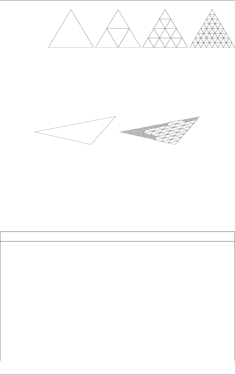
5 Acceleration structures 5.11 Opacity micromaps
0
Subdivision Level:
1
2
3
Micro-Triangle Count:
1
4 16
64
Fig. 5.1 - Microtriangle subdivision
The OMM specifies one of four opacity states per microtriangle: opaque, transparent,
unknown-opaque or unknown-transparent. An OMM is applied to one or more base
triangles in a GAS to add extra opacity detail, much like traditional texture mapping.
Figure 5.2 shows examples of OMM detail applied to a base triangle.
Fig. 5.2 - Opacity micromap detail on base triangle
5.11.1 Opacity micromap arrays
Unlike triangles, the OMMs are not stored directly in the geometry acceleration structures
(GAS), but instead reside in a separate resource, an opacity micromap array. Individual OMMs
may be referenced by triangles from within a GAS. Because OMM storage is separate from
the GASes, they can be reused within and across multiple GASes in a scene. Like acceleration
structures, OMM arrays are created on the device using the functions
optixOpacityMicromapArrayComputeMemoryUsage and
optixOpacityMicromapArrayBuild.
Listing 5.17
OptixMicromapBufferSizes bufferSizes = {};
optixOpacityMicromapArrayComputeMemoryUsage(
optixContext, &buildInput, &bufferSizes);
void* d_micromapArray;
void* d_tmp;
cudaMalloc(&d_micromapArray, bufferSizes.outputSizeInBytes);
cudaMalloc(&d_tmp, bufferSizes.tempSizeInBytes);
OptixMicromapBuffers buffers = {};
buffers.output = d_micromapArray;
buffers.outputSizeInBytes = bufferSizes.outputSizeInBytes;
buffers.temp = d_tmp;
buffers.tempSizeInBytes = bufferSizes.tempSizeInBytes;
42 NVIDIA OptiX 7.7 ± Programming Guide © 2023 NVIDIA Corporation

5.11 Opacity micromaps 5 Acceleration structures
OptixResult results = optixOpacityMicromapArrayBuild(
optixContext, cuStream, &buildInput, &buffers);
The functions use a single OptixOpacityMicromapArrayBuildInput struct specifying the set
of OMMs in the array. The build input specifies a device buffer of raw OMM data and a
device buffer with per OMM OptixOpacityMicromapDesc structs. The descriptors specify
the format and size of each OMM and its location within the raw OMM data buffer. The input
also specifies a host buffer of OptixOpacityMicromapHistogramEntry structs. This specifies
a histogram over opacity micromaps in the build input, binned by input format and
subdivision level combinations. Counts of histogram bins with equal format and subdivision
combinations are added together. The descriptors in the input buffer don’t need to appear in
any particular order, as long as the counts match the input histogram.
Listing 5.18
OptixOpacityMicromapHistogramEntry histogram[2];
Create micromap histogram
histogram[0].count = 2;
histogram[0].subdivisionLevel = 9;
histogram[0].format =
OPTIX_OPACITY_MICROMAP_FORMAT_2_STATE;
Two 1-bit OMMs of level 9
histogram[1].count = 1;
histogram[1].subdivisionLevel = 8;
histogram[1].format =
OPTIX_OPACITY_MICROMAP_FORMAT_4_STATE;
One 2-bit OMM of level 8
OptixOpacityMicromapDesc hostPerMicromapDescBuffer[2] = {...};
unsigned micromapUsageCounts = histogram[0].count + histogram[1].count;
size_t perMicromapDescBufferSizeInBytes =
micromapUsageCounts * sizeof(OptixOpacityMicromapDesc);
size_t inputBufferSizeInBytes =
histogram[0].count *
(1 << (max(3,2 * histogram[0].subdivisionLevel) - 3)) +
histogram[1].count *
(1 << (max(2,2 * histogram[1].subdivisionLevel) - 2));
All OMMs
are byte
alinged
std::vector<OptixOpacityMicromapDesc> h_perMicromapDescBuffer(
micromapUsageCounts);
std::vector<char> h_inputBuffer(inputBufferSizeInBytes);
...
Setup OMM descriptors and input data.
void* d_perMicromapDescBuffer;
void* d_inputBuffer;
cudaMalloc(d_perMicromapDescBuffer, perMicromapDescBufferSizeInBytes);
cudaMalloc(d_inputBuffer, inputBufferSizeInBytes);
© 2023 NVIDIA Corporation NVIDIA OptiX 7.7 ± Programming Guide 43
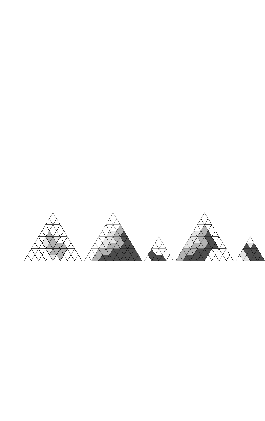
5 Acceleration structures 5.11 Opacity micromaps
cudaMemcpy(
d_perMicromapDescBuffer, h_perMicromapDescBuffer.data(),
perMicromapDescBufferSizeInBytes, cudaMemcpyHostToDevice );
cudaMemcpy(
d_inputBuffer, h_inputBuffer.data(),
inputBufferSizeInBytes, cudaMemcpyHostToDevice );
OptixOpacityMicromapArrayBuildInput buildInput = {};
buildInput.flags = OPTIX_OPACITY_MICROMAP_FLAG_NONE;
buildInput.inputBuffer = d_inputBuffer;
buildInput.perMicromapDescBuffer = d_perMicromapDescBuffer;
buildInput.numMicromapHistogramEntries = 2;
buildInput.micromapHistogramEntries = histogram;
The OMM arrays are opaque data structures, but the application is responsible for memory
management. The amount of memory required for a OMM array can be queried by passing
the build input to optixOpacityMicromapArrayComputeMemoryUsage.
The OMM array constructed by optixOpacityMicromapArrayBuild does not reference any
of the device buffers referenced in the build input. All relevant data is copied from these
buffers into the OMM array output buffer, possibly in a different format. The application is
free to release the input memory after the build without invalidating the OMM array.
Figure 5.3 shows an example of a collection of OMMs in an OMM array.
0Index:
1 2
3
4
Fig. 5.3 - Collection of opacity micromaps on a base triangle
Like acceleration structures, OMM arrays can be copied freely in memory, but the
optixOpacityMicromapArrayRelocate function must be called with the target location
address before the relocated OMM array is used in any BVHs. (See
“Relocation” (page 29).)
5.11.2 Usage
5.11.2.1 Construction of the geometry acceleration structure
The application can attach one OMM array per triangle geometry input to the GAS build.
Figure 5.4 (page 45) shows the relationship between OMM arrays and the acceleration
structure hierarchy.
44 NVIDIA OptiX 7.7 ± Programming Guide © 2023 NVIDIA Corporation
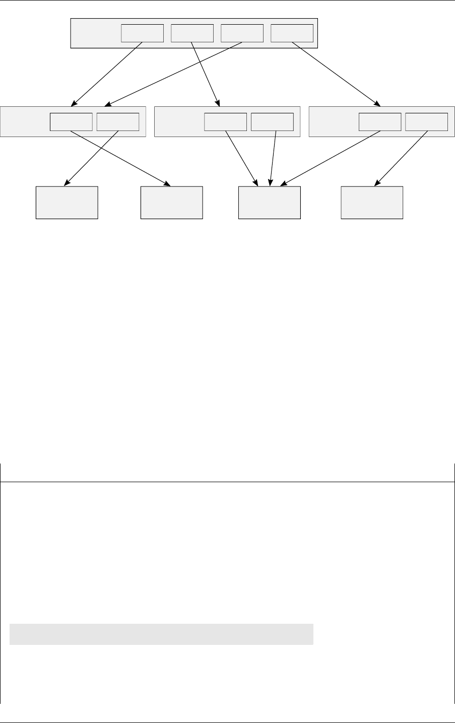
5.11 Opacity micromaps 5 Acceleration structures
structure
acceleration
Geometry
Build inputBuild input
structure
acceleration
Geometry
Build inputBuild input
structure
acceleration
Geometry
Build inputBuild input
Opacity
micromap array
structure
acceleration
Instance
Instance Instance Instance Instance
Opacity
micromap array
Opacity
micromap array
Opacity
micromap array
Fig. 5.4 - Opacity micromap arrays and the acceleration structure hierarchy
The OMM array is specified using the OptixBuildInputOpacityMicromap struct. OMM can
be indexed using an index buffer in device memory, with one OMM index per triangle.
Instead of an actual index, predefined indices (with names in the form
OPTIX_OPACITY_MICROMAP_PREDEFINED_INDEX_*) can be used to indicate that there is no OM
for this triangle, but the triangle has a uniform opacity state, and the selected behavior is
applied to the entire triangle.
The input also specifies a host buffer of OptixOpacityMicromapUsageCount structs. This
specifies the usage counts over opacity micromaps in the acceleration structure build input,
binned by input format and subdivision level combinations. Counts of bins with equal format
and subdivision combinations are added together. Duplicate use of OMMs in the GAS build
input must be included in this count, while OMMs that occur in the OMM array but are not
referenced by the GAS build input are not to be included in these counts. Note that this buffer
differs from the histogram passed to the OMM array build, which only specifies the
occurences of OMMs in the OMM array, irrespective of use by GAS build inputs.
Listing 5.19
OptixBuildInputOpacityMicromap opacityMicromap = {};
int h_indexBuffer[] = {
1, OPTIX_OPACITY_MICROMAP_PREDEFINED_INDEX_FULLY_OPAQUE 0, ...
};
cudaMemcpy(
d_indexBuffer, h_indexBuffer, sizeof(h_indexBuffer),
cudaMemcpyHostToDevice);
OptixOpacityMicromapUsageCount count[2] = { ... };
Create micromap
histogram
opacityMicromap.indexingMode =
OPTIX_OPACITY_MICROMAP_ARRAY_INDEXING_MODE_INDEXED;
opacityMicromap.indexBuffer = d_indexBuffer;
© 2023 NVIDIA Corporation NVIDIA OptiX 7.7 ± Programming Guide 45

5 Acceleration structures 5.11 Opacity micromaps
opacityMicromap.opacityMicromapArray = d_micromapArray;
opacityMicromap.indexSizeInBytes = 4;
opacityMicromap.numMicromapUsageCounts = 2;
opacityMicromap.micromapUsageCounts = count;
OptixBuildInputTriangleArray triangleInput = {};
...
triangleInput.opacityMicromap = opacityMicromap;
If a GAS has been built with the OPTIX_BUILD_FLAG_ALLOW_OPACITY_MICROMAP_UPDATE
build flag, it is possible to assign a different OMM array and OMM indices when updating a
GAS. GAS builds using OMM arrays as input will continue to refer to these OMM Arrays. If
an OMM array is overwritten with new OMM data, any GASes referencing it become stale
and must be updated.
5.11.2.2 Traversal
To render any triangles with OMMs, OMMs must be enabled in the pipeline using
allowOpacityMicromaps in the OptixPipelineCompileOptions struct. If OMMs are known
not to be used, it is more efficient to not specify the flag. If the flag is omitted and an OMM is
encountered during ray traversal, behavior is undefined.
Listing 5.20
OptixPipelineCompileOptions options = {};
...
options.allowOpacityMicromaps = true;
When a ray intersects a triangle with an OMM attached, the intersection point within the
barycentric space of the triangle is used to look up the opacity at that location through the
OMM. OMMs classify microtriangles as opaque, transparent, or unknown.
Opaque The hit is treated as a hit against a geometry with the
OPTIX_GEOMETRY_FLAG_DISABLE_ANYHIT flag set.
Transparent The hit is ignored and traversal resumes.
Unknown The hit is treated as a hit against a geometry without the
OPTIX_GEOMETRY_FLAG_DISABLE_ANYHIT flag set.
The two microtriangles states unknown-opaque and unknown-transparent are both treated as
unknown. However, using the OPTIX_RAY_FLAG_FORCE_OPACITY_MICROMAP_2_STATE ray
flag or OPTIX_INSTANCE_FLAG_FORCE_OPACITY_MICROMAP_2_STATE instance flag they can be
forced to be opaque and transparent, respectively. This redefinition affords some flexibility of
interpretation: in some ray-traced effects, exact resolution is not required and eliminating all
any-hit program invocation is visually acceptable. For example, soft shadows may be
resolved using a lower resolution proxy. The OPTIX_GEOMETRY_FLAG_DISABLE_ANYHIT flag is
ignored for triangles which have OMMs attached, as OMMs give much more fine-grained
control and are intended to replace the geometry-wide state where possible.
Ray flags and instance flags may still alter the state of opaque hits, but note that any such
flags are only applied after the OMM hit classification has occurred. This means that once the
46 NVIDIA OptiX 7.7 ± Programming Guide © 2023 NVIDIA Corporation
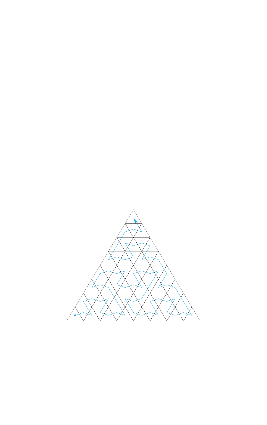
5.12 Displaced micro-meshes 5 Acceleration structures
OMM has been evaluated, there is no way to turn a transparent microtriangle miss into a hit
even by using the OPTIX_RAY_FLAG_DISABLE_ANYHIT ray flag or
OPTIX_INSTANCE_FLAG_DISABLE_ANYHIT instance flag.
It is still possible to turn off OMMs and revert to the geometry-specified behavior for
individual instances using the OPTIX_INSTANCE_FLAG_DISABLE_OPACITY_MICROMAPS
instance flag. This flag is only valid if the referenced BLAS was originally built with the
OPTIX_BUILD_FLAG_ALLOW_DISABLE_OPACITY_MICROMAPS build flag. Disabling OMMs on a
per-instance basis may be useful to implement certain level-of-detail schemes.
5.11.3 Encoding
OMM are bit masks of one or two bits per microtriangle.
A 1-bit OMM encodes each microtriangle as either transparent
(OPTIX_OPACITY_MICROMAP_STATE_TRANSPARENT) or opaque
(OPTIX_OPACITY_MICROMAP_STATE_OPAQUE) and never requires any-hit program invocation
during the tracing of a ray.
A 2-bit OMM is used if there are portions of the opacity that need to be resolved in an any-hit
program. The 2-bit OMM encodes each microtriangles as either transparent, opaque,
unknown-transparent (OPTIX_OPACITY_MICROMAP_STATE_UNKNOWN_TRANSPARENT) or
unknown-opaque (OPTIX_OPACITY_MICROMAP_STATE_UNKNOWN_OPAQUE).
The OMM microtriangle states are organized along a space-filling curve in barycentric space,
as illustrated in Figure 5.5.
Fig. 5.5 - Order of microtriangle states in a base triangle
The mapping of microtriangle into base triangle barycentric space is implemented by the
helper function optixMicromapIndexToBaseBarycentrics, made available by including the
header file optix_micromap.h .
5.12 Displaced micro-meshes
As scenes increasingly add more geometric complexity, moving into the range of billions or
even trillions of triangles, the storage requirements (as well as geometry acceleration
structure build times) grow substantially. To achieve the goal of dramatically increased
© 2023 NVIDIA Corporation NVIDIA OptiX 7.7 ± Programming Guide 47
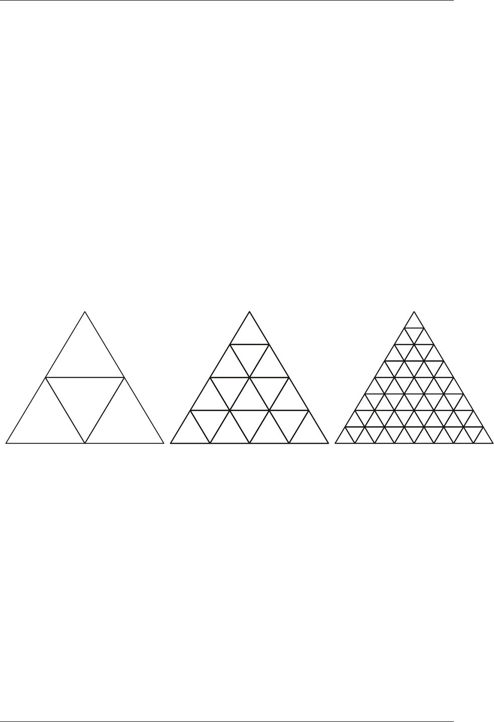
5 Acceleration structures 5.12 Displaced micro-meshes
geometric quality at sub-par storage costs, OptiX provides the builtin displaced micro-mesh
triangle primitive.
Very high-definition geometric content is typically coherent, which the new primitive exploits
for compactness. Displacement micro-maps, or DMMs, add high frequency geometric detail
to base triangles, resulting in a displaced micro-mesh. Individual DMMs only store
information about how to modulate a base triangle to add the extra detail, much like
traditional texture mapping.
The primitive was introduced with the NVIDIA Ada Lovelace generation GPUs (RtCores
version 3.0) with native hardware support. OptiX also provides software support on all
previous RTX-enabled GPUs (with RtCores version 1.0 and 2.0).
5.12.1 Displaced micro-meshes
Displaced micro-meshes are constructed by applying a scalar displacement field to a regular
triangle with displacement directions at its vertices. The initial displacement positions on the
triangle are defined by a uniform 2
N
x 2
N
subdivision of the barycentric grid on the triangle.
A uniform tessellation is applied, leading to 4
N
micro-triangles. The application specifies the
subdivision level N and hereby the amount of added micro-triangles. OptiX supports
subdivision levels from 0 to 5, resulting in up to 1024 micro-triangles.
Subdivision level
1 (4 micro triangles)
2 (16 micro triangles) 3 (64 micro triangles)
Fig. 5.6 - Subdivision scheme levels
The positions of the vertices of the micro-triangles are computed as follows. Each displaced
micro-triangle vertex, or micro-vertex, has an associated scalar displacement amount in range
[0,1] which is used to displace the micro-vertex from a base triangle along a displacement
direction. The displacement direction is computed by a barycentric (linear) interpolation of
three input displacement directions. The input displacement directions are defined by the
application for the three vertices of the base triangle. The length of the displacement
directions specifies the maximum amount of possible displacement. The scalar displacement
values used to compute a displaced micro-mesh from a base triangle are stored compactly
together in a displacement micro-map (DMM).
48 NVIDIA OptiX 7.7 ± Programming Guide © 2023 NVIDIA Corporation
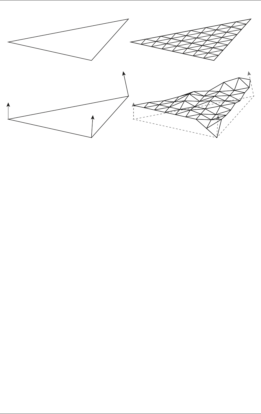
5.12 Displaced micro-meshes 5 Acceleration structures
Fig. 5.7 - Micro-map displacement detail being applied on a triangle
OptiX provides an additional optional mechanism to define the base triangle that is similar to
the “pretransform” mechanics of geometry acceleration structure builds. Instead of using the
application-provided input vertices directly, it is possible to displace these along the
displacement directions by a application-defined bias to define the base triangle. As such an
input triangle consisting of three vertex positions is supplied by the application to the
geometry acceleration structure build operation, along with input displacement directions,
scales, and biases per vertex. These inputs are combined to create a base triangle and
displacement directions that together define the possible range of displacements. An example
can be viewed in
Figure 5.8 (page 50). More concisely, the base triangle vertex positions and
displacement directions are computed using the following equations:
BasePosition = InputPosition + InputDisplacementDirection × Bias
DisplacementDirection = FloatToHalf( InputDisplacementDirection × Scale )
On the left in Figure 5.8, a base triangle and scaled displacement directions constructed from
the geometry acceleration structure inputs. On the right is a displaced micro-mesh. The green
and blue triangles are constructed from the biased base triangle vertices and scaled
displacement directions and define the minimum and maximum bounds for the possible
displacements.
© 2023 NVIDIA Corporation NVIDIA OptiX 7.7 ± Programming Guide 49
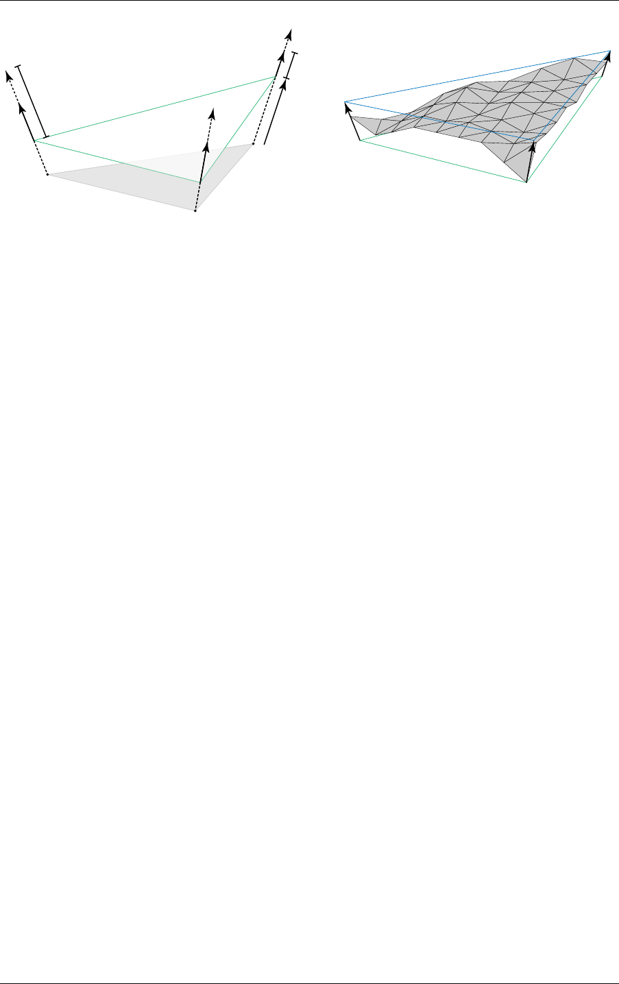
5 Acceleration structures 5.12 Displaced micro-meshes
Input triangle
Bias
Scale
Input displacement
direction
Base triangle
Displacement
direction
Base triangle
Max. displacement
Fig. 5.8 - Base vertices and scaled displacement directions
Althought the position bias and displacement direction scale are optional, they add some
additional control over the displacement range. The biased input vertices (the base vertices)
and the scaled displacement directions together define a bounding prismoid containing the
possible displacements, with the minimum and maximum displacements each forming a
triangle cap.
The base triangle positions and (scaled) displacement directions are linearly interpolated for
each micro-vertex according to the barycentric position of the micro-vertex. The final
micro-triangle vertex position is then computed by moving from the interpolated base
position along the interpolated displacement direction by the amount specified by the
corresponding micro-vertex entry in the attached DMM. This process can be summarized
with the following equations:
µVtxBasePosition = Lerp( BasePositions, µVtxBarycentrics )
µVtxDisplacementVector = Lerp( DisplacementVectors, µVtxBarycentrics )
µVtxDisplacementPosition = µVtxBasePosition + µVtxDisplacementVector × µVtxDisplacementAmount
A note on precision and performance: while all operations are performed in 32 bit precision,
the (scaled) displacement vectors are intermediately stored in half (16 bit) floating point
precision in the AS. The displacement amounts are represented using 11 bit unorm values for
compactness, allowing for 2048 possible displacements uniformly distributed between the
minimum and maximum triangle caps along the interpolated displacement direction. For
performance reasons, it is recommended to keep the bounding prismoid as tight as possible
around the displaced micro-triangles. This also helps ensuring that the 11 bit displacement
range is well utilized. Bias and scale can be used as tools to tighten the prismoid. However, it
is the applications responsibility to ensure that neighboring displaced micro-mesh triangle
primitive use that same bias and scale to ensure bit-exactness at the edge, which is required
for watertighness.
5.12.2 Displacement micro-maps
Displacement micro-maps (DMMs) contain the scalar displacement values of micro-vertices
compactly independent of the base triangle. The concept is very similar to opacity
micro-maps, normal maps, or any other textures. A displacement micro-map is the aggregate
of the storage of scalar displacement values, a subdivision level and the encoding format of
the displacement values.
Displacement amounts are stored in displacement blocks, each covering a triangular region of
micro-triangles. This triangular region is called sub-triangle and corresponds to exactly one
displacement block. Depending on the subdivision level and encoding format, one or more
50 NVIDIA OptiX 7.7 ± Programming Guide © 2023 NVIDIA Corporation
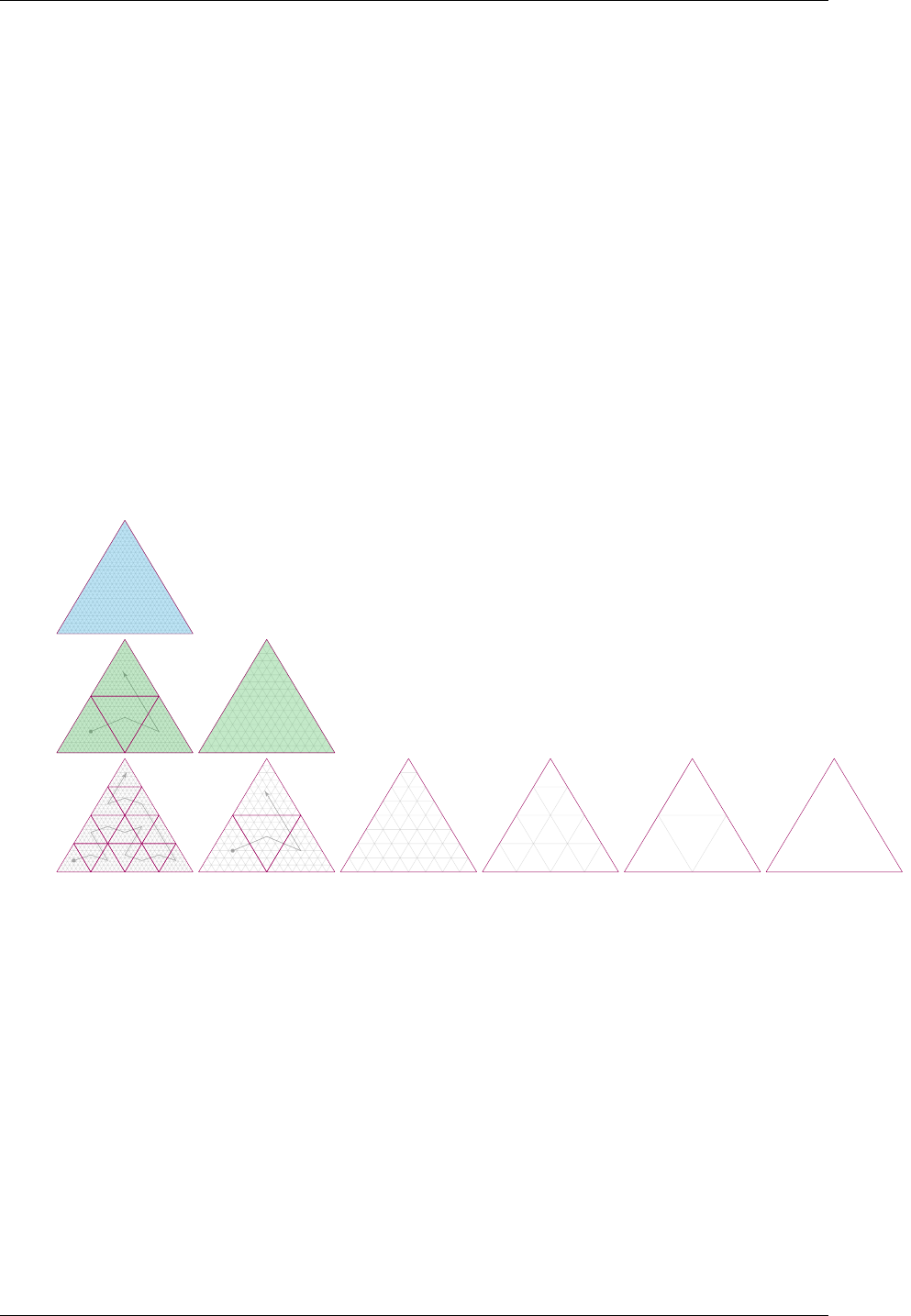
5.12 Displaced micro-meshes 5 Acceleration structures
displacement blocks (sub-triangles resp.) are required to store all displacement values for a
given displacement micro-map. OptiX offers three different displacement block encodings,
covering 64, 256, and 1024 micro-triangles per sub-triangle respectively. The different
encodings allow for a trade off between displacement precision and storage requirements. A
DMM can only use one of these encodings across all of its sub-triangles, hereby defining the
data layout of the displacement blocks. The maximum subdivision level for a displacement
micro-map is 5 (1024 micro-triangles). The full set of possible subdivision levels and block
encodings can be viewed in Figure 5.9. While neighboring sub-triangles share an edge by
construction, the corresponding displacement blocks do not share displacement values at the
edge. Instead, both displacement blocks need to specify the same displacement values for the
micro-vertices at the edge.
The sub-triangles are organized along a space-filling curve to cover all micro-triangles of the
DMM as shown in Figure 5.9. The curve defines the relative placement of the sub-triangles
within the barycentric grid and also the expected order of the displacement blocks in
memory. The space-filling curve is hierarchical and can in theory be applied to any
subdivision level. As such the curve also orders the micro-triangles within a sub-triangle as
well as globally within the DMM (
Figure 5.10 (page 52)). Note that this is the same
space-filling curve as used by opacity micro-maps.
Subdivision level
5
(1024 micro triangles)
4
(256 micro triangles)
3
(64 micro triangles)
2
(16 micro triangles)
1
(4 micro triangles)
0
(1 micro triangle)
Block format
1024 micro triangles
128 bytes
/ block
256 micro triangles
128 bytes
/ block
64 micro triangles
64 bytes
/ block
Fig. 5.9 - The available set of possible displacement block configurations in a DMM
As shown in Figure 5.9, depending on the block encoding and subdivision level, multiple
blocks may be needed to cover the total micro-triangle count of the DMM. The order of the
blocks in these cases follows a space-filling curve as indicated by the gray paths.
© 2023 NVIDIA Corporation NVIDIA OptiX 7.7 ± Programming Guide 51
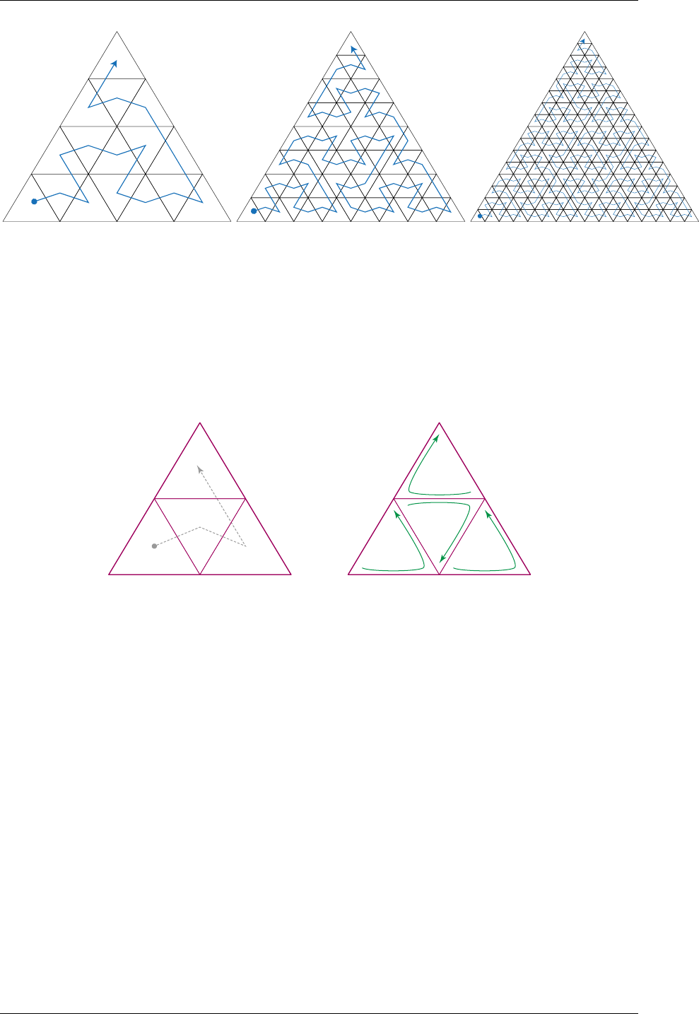
5 Acceleration structures 5.12 Displaced micro-meshes
Fig. 5.10 - The space filling curve covering 16, 64, or 256 micro-triangles (corresponding to subdivision levels 2-4). The
space filling curve index is the integer distance along the curve.
To maintain that the hierarchical ordering is contiguous, some sub-triangles are flipped and
wound differently. Sub-triangle A in Figure 5.11 is constructed with the v0, v01, and v20
corner vertices. The middle triangle, M, then starts at v20, goes to v12, and then v01. M is
flipped vertically, and C is flipped horizontally, meaning that the winding is flipped for both
of these triangles, as can be seen in Figure 5.11.
v0
v01
v1
v12
v2
v20
A
M
B
C
v0
v01
v1
v12
v2
v20
A
M
B
C
Fig. 5.11 - Left: Sub-triangle ordering at each step of hierarchical splitting. At each
split, enter at A, then go to M (middle) and B, and finally exit at C. Right: Vertex
ordering of each hierarchically split sub-triangle.
Flipping the winding direction needs to be taken into account when setting the displacement
values of a displacement block. The first displacement value of the displacement block
corresponding to sub-triangle A is at v0, while the first displacement value of the
displacement block corresponding to sub-triangle M is at v20, and the first displacement
value of the displacement block corresponding to sub-triangle C is at v12.
Figure 5.12
(page 53) shows the orientation of all sub-triangles for the three possible counts (1, 4, or 16) of
sub-triangles of a DMM.
52 NVIDIA OptiX 7.7 ± Programming Guide © 2023 NVIDIA Corporation
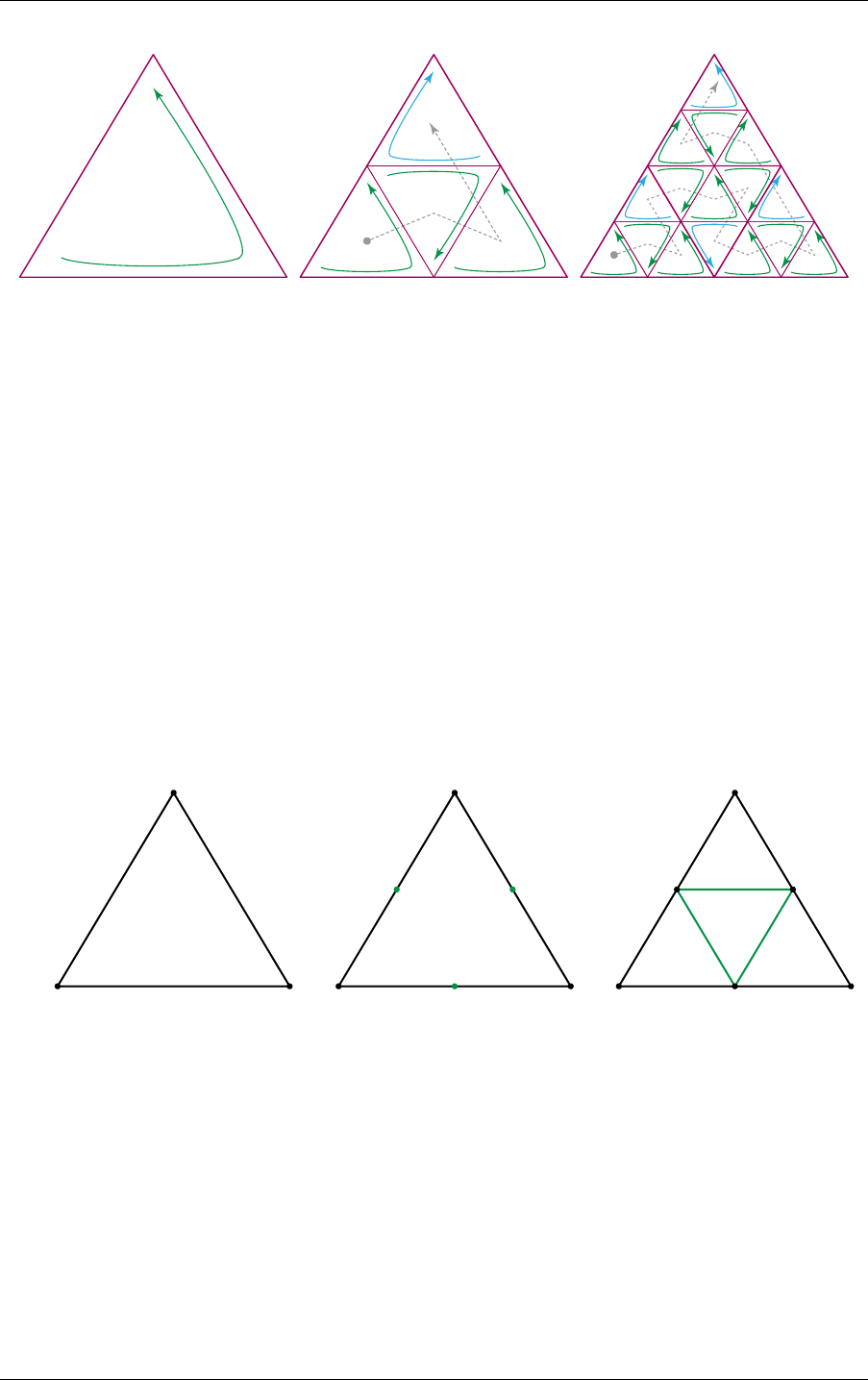
5.12 Displaced micro-meshes 5 Acceleration structures
Number of sub triangles
1 4 16
Fig. 5.12 - Illustration of how sub-triangles flip horizontally and vertically at different levels. Green arrows
indicate that the winding is unchanged or only flipped vertically for the hierarchy level above, while blue arrows
indicate a flip in horizontal winding. The dotted line traces out the space filling curve order in which the
corresponding displacement blocks are encoded.
5.12.2.1 Displacements blocks
The order of the displacement values locally within a block (the order of the micro-vertices)
follows a hierarchical splitting scheme based on the space-filling curve. The first three values
correspond to the vertices of the sub-triangle this block is applied to (subdivision level 0 wrt.
the sub-triangle). The following three values correspond to the vertices when splitting the
edges of the sub-triangle (subdivision level 1 wrt. the sub-triangle). In particular, each
subdivision level adds a new vertex on every edge connecting two vertices of the prior
subdivision level, splitting each triangle into four, as seen in Figure 5.13:
0 1
2
v
wu
A
0 1
2
5
43
0 1
2
5
43
Subdivide upright triangle A.
1. split edge u
2. split edge w
3. split edge v
Fig. 5.13 - Splitting the edges of a triangle to create new vertices. A triangle is split into four new smaller
triangles
For every subdivision level, the order of the new vertices is derived from the following rules.
The hierarchical subdivision is executed by splitting only the upright (not vertically flipped
triangles) triangles. For a given upright triangle, first edge u, then w, and finally v is split to
introduce new vertices as shown in Figure 5.13.
Next, the splitting is continued by looping over the triangles following the space-filling curve,
introducing new vertices as shown above for all upright triangles. Once all triangles are split
for a given subdivision level, the process is repeated for the next subdivision level as shown
in
Figure 5.14 (page 54).
© 2023 NVIDIA Corporation NVIDIA OptiX 7.7 ± Programming Guide 53
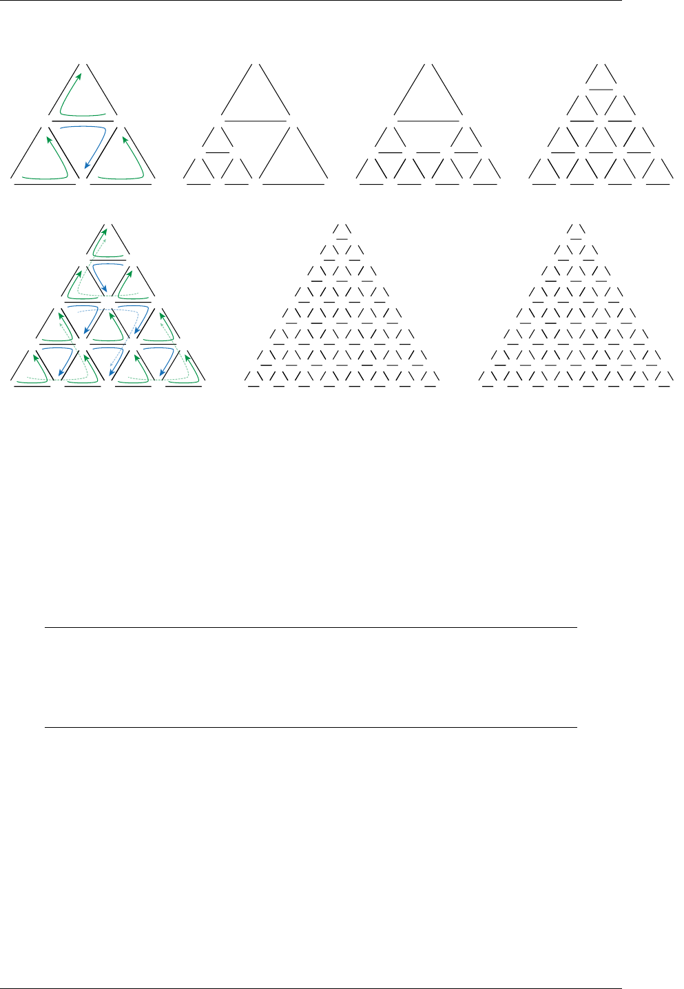
5 Acceleration structures 5.12 Displaced micro-meshes
0
3
2
4
5 1
A
B
C
D
0
3
6 7
8
2
4
5 1
B
C
D
0
3
6 9 10
11
7
8
2
4
5 1
D
0
3
12 13
14
6 9 10
11
7
8
2
4
5 1
0
3
12 13
14
6 9 10
11
7
8
2
4
5 1
A
B
H J
C I K
D
E
G
F L
O
N
M
P
0 17
15 16
xx xx xx
xx xx xx xx
xx xx xx
xx xx
xx
xx xx xx xx xx xx
xx xx xx xx
xx xx
xx xx
3
12 13
14
6 9 10
11
7
8
2
4
5 1 0 17
15 16
20 29 32
18 19 27 28
23 26 35
41 38
44
21 22 24 25 33 34
39 40 36 37
42 43
30 31
3
12 13
14
6 9 10
11
7
8
2
4
5 1
Subdivide upright triangles A, C, D by splitting the edges of each triangle in a fixed order.
Subdivide upright
triangles
A, C, D,
F,
I, K, L,
M, O, P.
Fig. 5.14 - Applying the splitting to each upright triangle in the space-filling-curve order hierarchically orders the
displacement values in a displacement block.
5.12.2.1.1 Uncompressed displacement block format
The simplest of the block formats covers 64 micro-triangles (subdivision level 3). The 45 x 11
bits displacement values are stored bit packed in the order following in the vertex indexing
scheme above. The storage requirement for these values is 495b. Another two bits are
reserved for future use (at the very end of the block). The total size of the block is padded up
to 512b (= 64B), as shown in the table below:
64 tris, 64 B block
Field Entries Bits per entry Bit offset
Displacement amounts Vertex 0–44 45 11 0
Unused 1 15 495
Reserved Must be 0 1 2 510
Layout of the uncompressed 64 micro-triangle, 64 byte block
5.12.2.1.2 Compressed displacement block formats
With the 256 and 1024 micro-triangle block formats (corresponding to subdivision levels 4
and 5, respectively) it is possible to achieve higher compression rates than the 64
micro-triangle format. Both the 256 and 1024 micro-triangle formats occupy 128B, which offer
a 2x and 8x compression ratio respectively over the uncompressed 64 micro-triangle format.
While the 64 micro-triangle format can represent any combination of 11b displacement
amounts, the 256 and 1024 micro-triangle formats cannot, and instead rely on locally similar
displacements to extract compression. These compression formats thus allow encoders to
trade compression rate for geometric accuracy.
54 NVIDIA OptiX 7.7 ± Programming Guide © 2023 NVIDIA Corporation
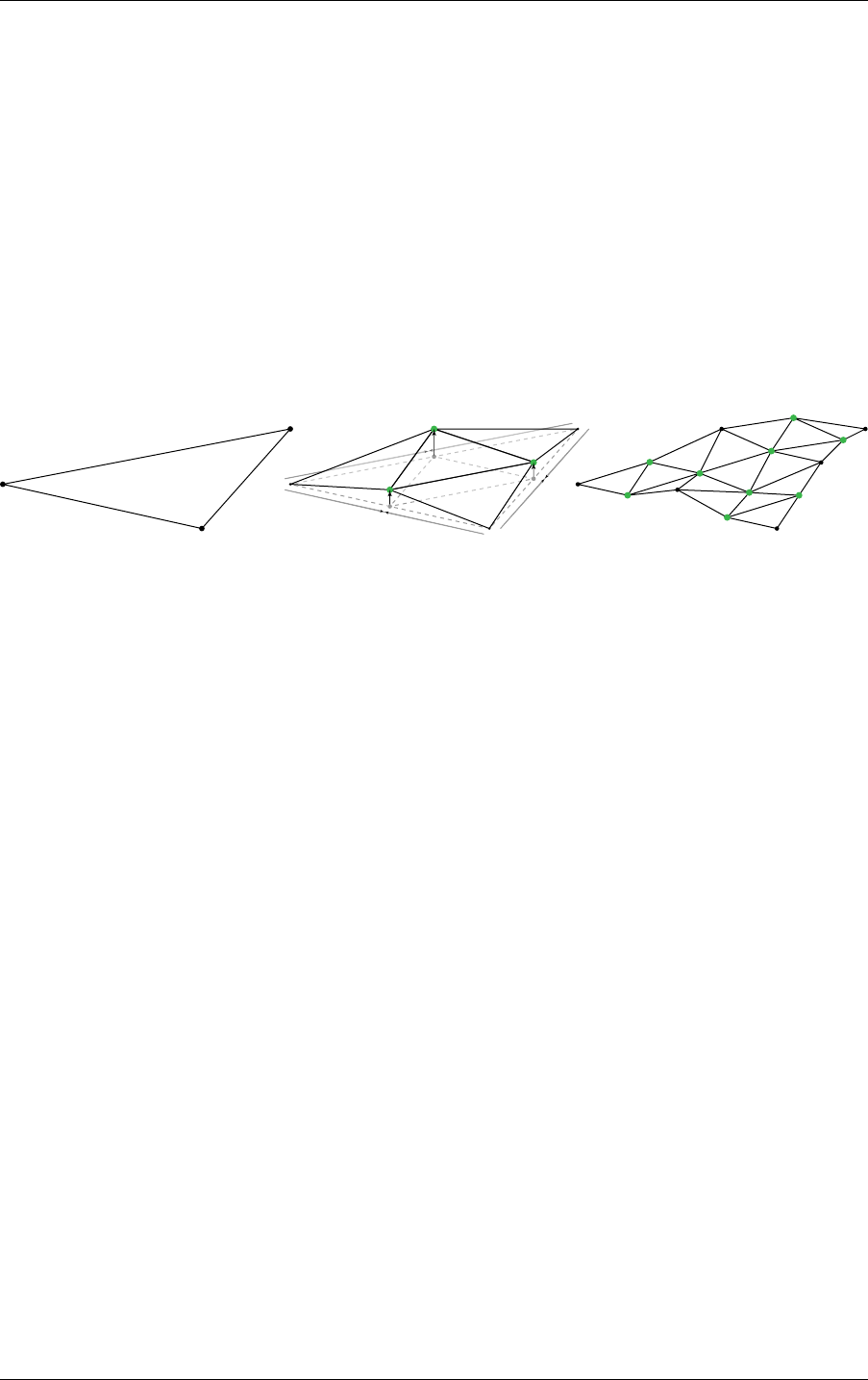
5.12 Displaced micro-meshes 5 Acceleration structures
The compression scheme relies on the natural recursive subdivision used to form a
micro-map, with each subdivision level introducing more and more vertices while using
fewer and fewer correction bits. At the coarsest subdivision level, three 11 bit anchor points
are specified for the starting vertices. At each level of subdivision, new vertices are formed by
averaging the two adjacent vertices in the lower level. This is the prediction step: treat the
unorm values as integers and predict the value as the rounded average of the two adjacent
values A and B:
Prediction = (A + B + 1) / 2
The next step corrects that prediction by adjusting it up or down to the correct location:
Decoded = Prediction + ( SignExtend( Correction ) « Shift[ Level ][ EdgeOrInterior ] )
This process is illustrated in Figure 5.15:
Fig. 5.15 - Displacement block compression: prediction and correction scheme
On the left in Figure 5.15, three anchor points at subdivision level 0. In the middle, three new
vertices (green) are introduced at subdivision level 1. The displacement amounts are
predicted by averaging the two neighbors, after which correction is applied. On the right at
subdivision level 2, nine new vertices are introduced to be predicted and corrected.
If the correction movements are small, or allowed to be stored lossy, the number of bits used
to correct the prediction can be smaller than the number of bits needed to directly encode it.
The bit width of the correction factors are variable per level. The base anchor points are
unsigned (11b unorm) while the corrections are signed (two’s complement). A shift value
allows for corrections to be stored at less than the full bit width. Shift values are stored per
level with 4 variants to allow vertices on each of the edges to be shifted independently from
each other and from internal micro-vertices, as seen in
Figure 5.16 (page 56). This allows to
pick shift values at the edges such that neighboring sub-triangles and DMMs can be matched
at the edge to ensure watertighness. Note that the decoded position does wrap when adding
the correction to the prediction. It is up to the encoder to either avoid wrapping based on
stored values or to make the wrapping outcome senseful.
© 2023 NVIDIA Corporation NVIDIA OptiX 7.7 ± Programming Guide 55
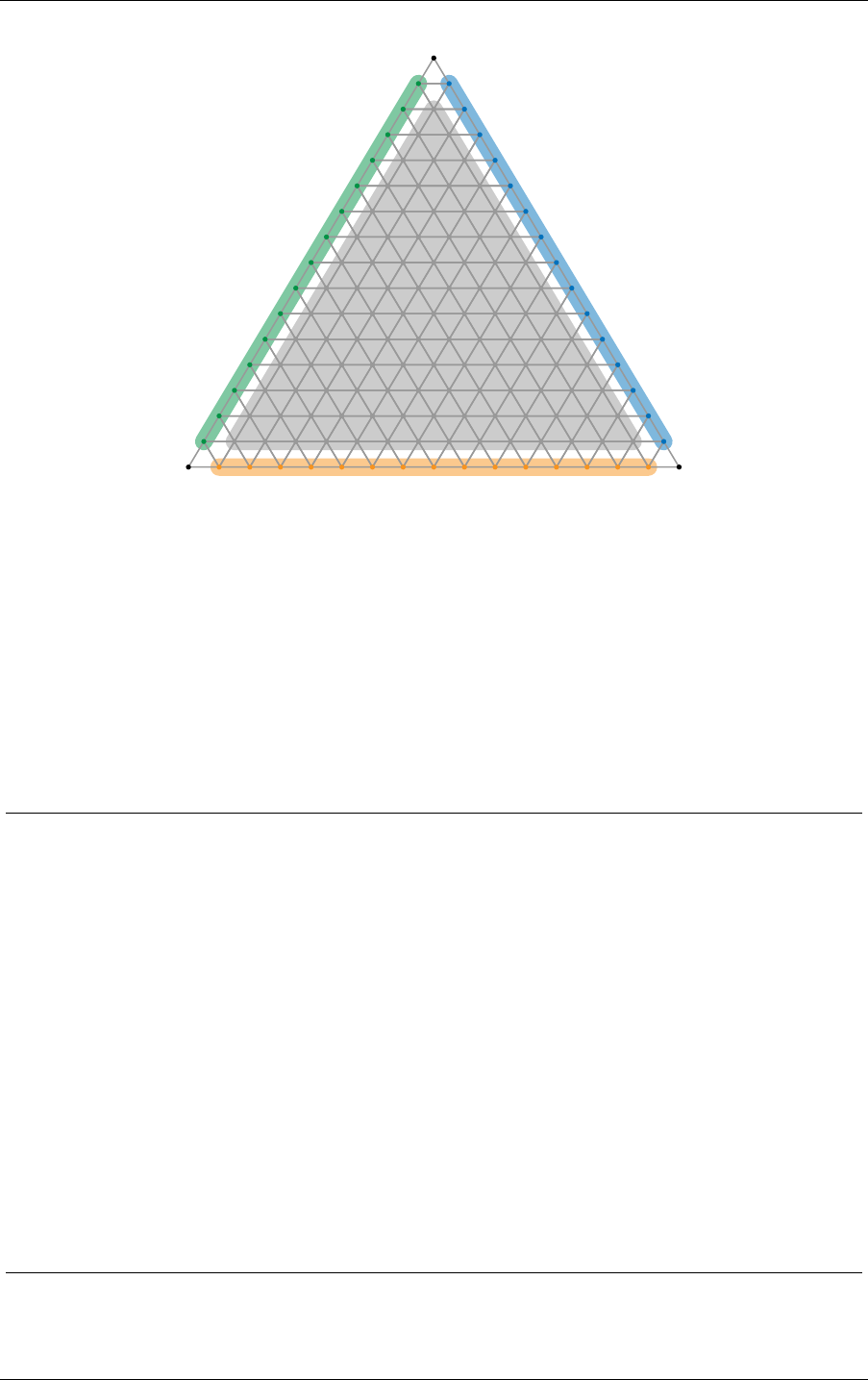
5 Acceleration structures 5.12 Displaced micro-meshes
v0 v1
v2
Fig. 5.16 - Different shift amounts can be assigned to each of the three edges and the interior of the displacement
block.
In Figure 5.16, the separate shifts allow for better control in matching edges with neighboring
sub-triangles. Also note that the shift values don’t apply to the anchor points as they are
always stored uncompressed in the displacement block.
The two compressed block formats both follow the same prediction and correction scheme,
and only differ in the bit allocations for the various fields. An overview of the format layout
can be found in the table below:
1024 tris,
128 B block
256 tris,
128 B block
Field Entries Bits per entry Bit offset Bits per entry Bit offset
Anchors Vertex 0 1 11 0 11 0
Vertex 1 1 11 11 11 11
Vertex 2 1 11 22 11 22
Corrections Level 1 corrections 3 11 33 11 33
Level 2 corrections 9 8 66 11 66
Level 3 corrections 30 4 138 10 165
Level 4 corrections 108 2 258 5 465
Level 5 corrections 408 1 474
Unused 1 88 882 1 1005
Shifts Level 5 shifts 4 4 970
Level 4 shifts 4 4 986 3 1006
Level 3 shifts 4 3 1002 1 1018
Level 2 shifts 4 2 1014
Reserved Must be 0 1 2 1022 2 1022
Bit distributions and layout of displacement block compression formats
56 NVIDIA OptiX 7.7 ± Programming Guide © 2023 NVIDIA Corporation
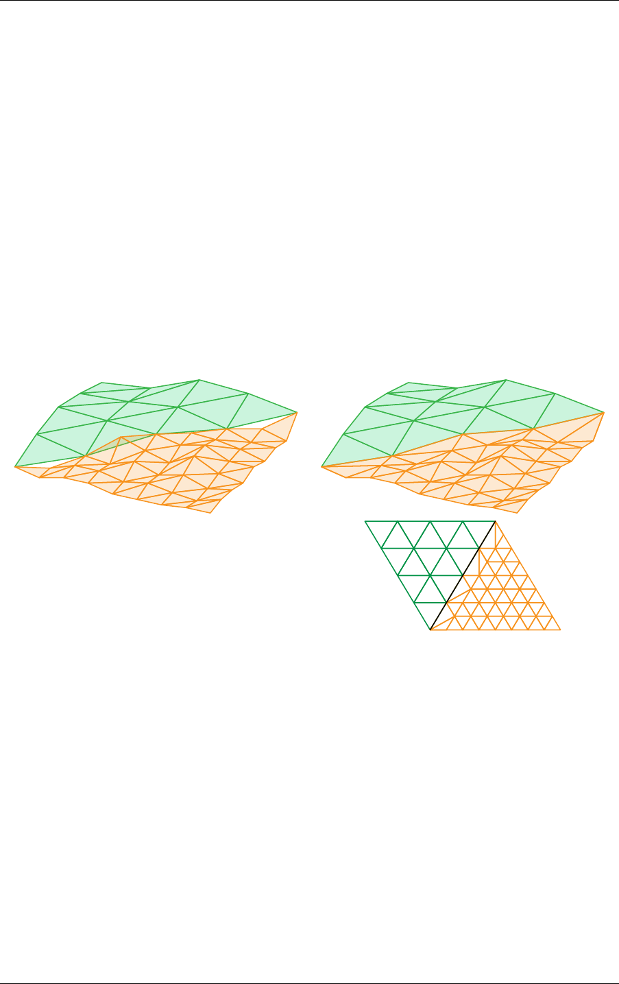
5.12 Displaced micro-meshes 5 Acceleration structures
5.12.2.2 Edge decimation
Adjacent triangles with different DMMs applied may differ in which subdivision levels are
used. This allows the amount of displacement detail to vary smoothly over the mesh. The
difference in subdivision level between two neighboring base triangles is limited to one level,
however. The change in levels though can propagate throughout the mesh such that, for
example, that level 3 base triangle is next to a level 4 base triangle which itself is next to a
level 5 base triangle.
When adjacent base triangles have different subdivision levels, the number of segments on
the shared edge differs by a factor of 2. This introduces T-junctions which introduce cracking,
as illustrated in the left image in Figure 5.17. In order to maintain watertightness across
varying resolutions, a stitching pattern is used along the edge of the higher resolution
triangles, as shown to the right in Figure 5.17.
It is the applications responsibility to ensure that there are no cracks within and between
neighboring displaced micro-mesh triangles. An edge of a displaced micro-mesh triangle can
be flagged to require edge decimation to match the topology of its neighboring displaced
micro-mesh triangle.
Fig. 5.17 - Edge decimation prevents cracking between displaced micro-mesh triangles with different subdivision
levels
In Figure 5.17, the left side shows two neighboring triangles with different subdivision level.
If this is not handled, there are cracks along the shared edges. On the right, the vertices at the
T-junctions are omitted, and the connectivity is changed using stitching pattern along the
edge.
© 2023 NVIDIA Corporation NVIDIA OptiX 7.7 ± Programming Guide 57
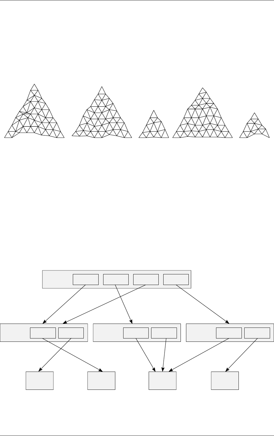
5 Acceleration structures 5.12 Displaced micro-meshes
5.12.3 Displaced micro-mesh API
The host API for displaced micro-meshes consists of two main parts: First, the interface for
specifying DMMs and constructing DMM arrays. Second, the specification of the displaced
micro-mesh triangle primitive build input to geometry acceleration structure as well as
referencing DMMs for the desired displacement.
5.12.3.1 Displacement micro-map arrays
0
DMM array index
1 2 3 4
Fig. 5.18 - Multiple DMMs are stored together in a DMM array. A specific DMM can be referenced by its index
in the DMM array.
Scalar displacement values are specified compactly in the form of DMMs, which are not
stored directly in the geometry acceleration structure, but in a separate resource, a
displacement micro-map array, see Figure 5.18. The DMM array can be referenced when
building a geometry acceleration structure and individual DMMs may then be referenced by
triangles from within a geometry acceleration structure as shown in Figure 5.19. Because
DMM storage is separate from the geometry acceleration structures, DMMs can be reused
within and across multiple geometry acceleration structures in a scene. Similar to acceleration
structures, DMM arrays are created on the device using the functions
optixDisplacementMicromapArrayComputeMemoryUsage and
optixDisplacementMicromapArrayBuild.
structure
acceleration
Geometry
Build inputBuild input
structure
acceleration
Geometry
Build inputBuild input
structure
acceleration
Geometry
Build inputBuild input
Displacement
micromap
array
Displacement
micromap
array
Displacement
micromap
array
Displacement
micromap
array
structure
acceleration
Instance
Instance Instance Instance Instance
Fig. 5.19 - DMM arrays are a separate resource that need to be built. DMM arrays can be re-used by multiple
geometry acceleration structures.
58 NVIDIA OptiX 7.7 ± Programming Guide © 2023 NVIDIA Corporation

5.12 Displaced micro-meshes 5 Acceleration structures
Listing 5.21
OptixMicromapBufferSizes bufferSizes = {};
optixDisplacementMicromapArrayComputeMemoryUsage(
optixContext, &dmmArrayBuildInput, &bufferSizes);
void* d_displacementMicromapArray;
void* d_tmp;
cudaMalloc(&d_displacementMicromapArray, bufferSizes.outputSizeInBytes);
cudaMalloc(&d_tmp, bufferSizes.tempSizeInBytes);
OptixMicromapBuffers buffers = {};
buffers.output = d_displacementMicromapArray;
buffers.outputSizeInBytes = bufferSizes.outputSizeInBytes;
buffers.temp = d_tmp;
buffers.tempSizeInBytes = bufferSizes.tempSizeInBytes;
OptixResult results = optixDisplacementMicromapArrayBuild(
optixContext, cuStream, &buildInput, &buffers);
The functions use a single OptixDisplacementMicromapArrayBuildInput struct specifying
the set of DMMs in the array. The build input specifies a device buffer of displacement blocks,
with formats and data layouts as described in the previous section. DMM arrays are a
collection of DMMs that can have different subdivision levels and formats. Therefore, the
build input also references a device buffer with per DMM OptixDisplacementMicromapDesc
structs. The descriptors specify the format and size of each DMM and its corresponding
displacement blocks as well as its location within the DMM displacement values buffer. If a
DMM requires multiple displacement blocks (for example, a subdivision level 5 DMM with
the 256 micro-triangles / 128 bytes block format), it is expected that the displacement blocks
are consecutive in memory, in the order of the sub-triangles as detailed in the previous
section. The build input also specifies a host buffer of
OptixDisplacementMicromapHistogramEntry structs. This specifies a histogram over
displacement micro-maps in the build input, binned by input format and subdivision level
combinations. Counts of histogram bins with equal format and subdivision combinations are
added together. The descriptors in the input buffer don’t need to appear in any particular
order, as long as the counts match the input histogram. Similar to the AS builds, the DMM
array build offers a “fast trace” and “fast build” flag, each designed to favor trace
performance or build speed over the other. For non-interactive renderers it is generally
recommended to use “fast trace”. Also similar to AS builds, the device data doesn’t need to
be ready for consumption when calling
optixDisplacementMicromapArrayComputeMemoryUsage and only the histogram
information as well as flags for the DMM array build are consumed for the memory size
computation.
The DMM arrays are opaque data structures, but the application is responsible for memory
management. The amount of memory required for a OMM array can be queried by passing
the build input to optixDisplacementMicromapArrayComputeMemoryUsage.
The DMM array constructed by optixDisplacementMicromapArrayBuild does not reference
any of the device buffers referenced in the build input. All relevant data is copied from these
© 2023 NVIDIA Corporation NVIDIA OptiX 7.7 ± Programming Guide 59

5 Acceleration structures 5.12 Displaced micro-meshes
buffers into the DMM array output buffer, possibly in a different format. The application is
free to release the input memory after the build without invalidating the DMM array.
5.12.3.2 Geometry acceleration structure build for DMM triangles
Primitives of type displaced micro-mesh triangle use the same build input struct
(OptixBuildInputTriangleArray) as normal triangles. However, they provide the
additional displacement information (provided via the
OptixBuildInputDisplacementMicromap struct) to turn a normal triangle into a displaced
micro-mesh triangle. The DMMs in a DMM array only store the displacement amounts, all
other information is only specified as part of the geometry acceleration structure build input.
The application can attach one DMM array per triangle geometry input to the geometry
acceleration structure build. The DMM array is set via member
displacementMicromapArray. The indexing into the DMM array happens via an explicit
index buffer or an implicit one-to-one mapping by assuming the Nth triangle in the build
input uses the Nth DMM of the referenced DMM array. The displacement directions at the
vertices of the base triangles, the optional bias and scale, and additional flags (edge
decimation flags) are provided as buffers to the geometry acceleration structure build. The
displacement directions and optional bias and scale are per-vertex attributes and the
corresponding buffers are indexed just like the vertex position buffer. The flags buffer
contains per-triangle attributes and the Nth flag is applied to the Nth primitive in the build
input. Currently, the only available flags are the edge decimation flags, signaling the
intersector if edge decimation is supposed to be applied to an edge (see section edge
decimation). OptiX does not apply edge decimation automatically, nor verifies if edge
decimation is required at an edge.
In case an index buffer is used for the DMM array indexing, a stride between the indices as
well as the byte size of a single index is set using displacementMicromapIndexStrideInBytes
and displacementMicromapIndexSizeInBytes. The index can also be offset by a constant
using member displacementMicromapIndexOffset. The displacement directions, as well as
bias and scale can be specified as float or half precision values. However, in case of the
displacement directions, the API accepts float values purely for convenience, the values are
converted to the half format internally and all operations are performed using half precision
(see previous section).
The input also specifies a host buffer of OptixDisplacementMicromapUsageCount structs.
This specifies the usage counts over displacement micro-maps in the acceleration structure
build input, binned by input format and subdivision level combinations. Counts of bins with
equal format and subdivision combinations are added together. Duplicate use of DMMs in
the geometry acceleration structure build input must be included in this count, while DMMs
that occur in the DMM array but are not referenced by the geometry acceleration structure
build input are not to be included in these counts. Note that this buffer differs from the
histogram passed to the DMM array build, which only specifies the occurrences of DMMs in
the DMM array, irrespective of use by geometry acceleration structure build inputs.
Note that neither the reference to the DMM array nor the indexing from triangles to DMMs
are allowed to change in a geometry acceleration structure update.
60 NVIDIA OptiX 7.7 ± Programming Guide © 2023 NVIDIA Corporation

6 Program pipeline creation
The following API functions are described in this section:
optixModuleCreate
optixModuleDestroy
optixProgramGroupCreate
optixProgramGroupGetStackSize
optixPipelineCreate
optixPipelineDestroy
optixPipelineSetStackSize
Programs are first compiled into modules of type OptixModule. One or more modules are
combined to create a program group of type OptixProgramGroup. Those program groups are
then linked into an OptixPipeline on the GPU. This is similar to the compile and link
process commonly found in software development. The program groups are also used to
initialize the header of the SBT record associated with those programs.
The three create methods, optixModuleCreate, optixProgramGroupCreate, and
optixPipelineCreate take an optional log string. This string is used to report information
about any compilation that may have occurred, such as compile errors or verbose information
about the compilation result. To detect truncated output, the size of the log message is
reported as an output parameter. It is not recommended that you call the function again to
get the full output because this could result in unnecessary and lengthy work, or different
output for cache hits. If an error occurred, the information that would be reported in the log
string is also reported by the device context log callback (when provided).
Both mechanisms are provided for these create functions to allow a convenient mechanism
for pulling out compilation errors from parallel creation operations without having to
determine which output from the logger corresponds to which API invocation.
Symbols in OptixModule objects may be unresolved and contain extern references to
variables and __device__ functions.
These symbols can be resolved during pipeline creation using the symbols defined in the
pipeline modules. Duplicate symbols will trigger an error.
A pipeline contains all programs that are required for a particular ray-tracing launch. An
application may use a different pipeline for each launch, or may combine multiple
ray-generation programs into a single pipeline.
Most NVIDIA OptiX API functions do not own any significant GPU state; Streaming
Assembly (SASS) instructions, which define the executable binary programs in a pipeline, are
an exception. The OptixPipeline owns the CUDA resource associated with the compiled
SASS and it is held until the pipeline is destroyed. This allocation is proportional to the
amount of compiled code in the pipeline, typically tens of kilobytes to a few megabytes.
However, it is possible to create complex pipelines that require substantially more memory,
© 2023 NVIDIA Corporation NVIDIA OptiX 7.7 ± Programming Guide 61

6 Program pipeline creation 6.1 Program input
especially if large static initializers are used. Wherever possible, exercise caution in the
number and size of the pipelines.
Module lifetimes need to extend to the lifetimes of program groups that reference them. After
using modules to create an OptixPipeline through the OptixProgramGroup objects,
modules may be destroyed with optixModuleDestroy.
6.1 Program input
NVIDIA OptiX programs are encoded in either OptiX-IR, a proprietary intermediate
representation, or
PTX,
1
an instruction set for parallel thread execution. OptiX-IR contains a
richer representation of the code that enables symbolic debugging and provides opportunities
for enhanced optimizations and future features. OptiX-IR is a binary format that can only be
read by NVIDIA tools, unlike PTX, which is stored in plain-text format.
To create PTX programs, compile CUDA source files using the NVIDIA
nvcc offline
compiler
2
or nvrtc JIT compiler.
3
To create OptiX-IR programs, compile the CUDA source
files with nvcc. OptiX device headers should be included in the source files to provide the
device API for OptiX programs.
Transitioning from PTX to OptiX-IR input is recommended when using nvcc to generate code
for OptiX. PTX will continue to be supported but may not provide all OptiX-IR features, such
as symbolic debugging.
The following example uses nvcc to create an OptiX-IR program:
nvcc -optix-ir -Ipath-to-optix-sdk/include --use_fast_math myprogram.cu -o myprogram.optixir
The nvcc command-line options are explained in more detail as part of the usage description
of the compiler options displayed with nvcc --help.
Note the following requirements for nvcc and nvrtc compilation:
•
The streaming multiprocessor (SM) target of the input OptiX program must be less than
or equal to the SM version of the GPU for which the module is compiled.
•
To generate code for the minimum supported GPU (Maxwell), use architecture targets
for SM 5.0, for example, --gpu-architecture=compute_50. Because OptiX rewrites the
code internally, those targets will work on any newer GPU as well.
•
CUDA Toolkits 10.2 and newer throw deprecation warnings for SM 5.0 targets. These
can be suppressed with the compiler option -Wno-deprecated-gpu-targets.
If support for Maxwell GPUs is not required, you can use the next higher GPU
architecture target SM 6.0 (Pascal) to suppress these warnings.
•
Use --machine=64 (-m64). Only 64-bit code is supported in OptiX.
•
Define the output type with --optix-ir or --ptx. Do not compile to obj or cubin.
•
For debugging, use the debug flag -G. Symbolic debugging is currently only supported
for OptiX-IR and not PTX, though PTX compiled with debug support can be used as
input to OptiX. It may also be necessary to set the environment variable
1. https://docs.nvidia.com/cuda/parallel-thread-execution/
2. https://docs.nvidia.com/cuda/cuda-compiler-driver-nvcc/
3. https://docs.nvidia.com/cuda/nvrtc/
62 NVIDIA OptiX 7.7 ± Programming Guide © 2023 NVIDIA Corporation

6.2 Programming model 6 Program pipeline creation
OPTIX_FORCE_DEPRECATED_LAUNCHER to 1. If breakpoints are unable to be hit, try setting
this environment variable before starting your application.
•
Enable --relocatable-device-code=true (-rdc). Command nvcc can also use the
option --keep-device-functions, which is not supported by nvrtc. These flags
prevent the CUDA compiler from eliminating direct or continuation callables as dead
code.
•
To get smaller and faster code, enable --use_fast_math. This flag enables .approx
instructions for trigonometric functions and reciprocals, avoiding inadvertent use of
slow double-precision floats. For performance reasons, it is recommended that you set
this flag; the only exception is use cases that require more precision.
•
To profile your code with Nsight Compute,
4
enable --generate-line-info and set
debugLevel = OPTIX_COMPILE_DEBUG_LEVEL_MODERATE in the
OptixModuleCompileOptions in your application host code.
6.2 Programming model
The NVIDIA OptiX programming model supports the multiple instruction, multiple data
(MIMD) subset of CUDA. Execution must be independent of other threads. For this reason,
shared memory usage and warp-wide or block-wide synchronization — such as barriers —
are not allowed in the input PTX code. All other GPU instructions are allowed, including
math, texture, atomic operations, control flow, and loading data to memory. Special
warp-wide instructions like vote and ballot are allowed, but can yield unexpected results as
the locality of threads is not guaranteed and neighboring threads can change during
execution, unlike in the full CUDA programming model. Still, warp-wide instructions can be
used safely when the algorithm in question is independent of locality by, for example,
implementing warp-aggregated atomic adds. The special registers in PTX - defined in the
PTX IR
5
- are interpreted in OptiX as follows:
PTX Special Register Interpretation in OptiX
%tid launch index
%ntid launch dimension
%ctaid always equals to 0
%nctaid always equals to 1
%laneid unchanged, but volatile across trace calls
%warpid unchanged
%nwarpid unchanged
%smid unchanged
%nsmid unchanged
%gridid unchanged
%lanemask_eq, ... unchanged, but volatile across trace calls
%clock, ... unchanged
4. https://developer.nvidia.com/nsight-compute
5. http://cuda-internal/docs/cuda/gpgpu/current/parallel-thread-execution/index.html#special-registers
© 2023 NVIDIA Corporation NVIDIA OptiX 7.7 ± Programming Guide 63

6 Program pipeline creation 6.3 Module creation
%pm0, ... invalid PTX error
%pm0_64, ... invalid PTX error
%envreg0, ... invalid PTX error
%globaltimer, ... unchanged
%reserved_smem_offset_begin, ... invalid PTX error
%total_smem_size invalid PTX error
%dynamic_smem_size invalid PTX error
While the first four registers can be accessed through CUDA intrinsics, namely threadIdx,
blockDim, blockIdx and gridDim respectively, all other special registers require the use of
PTX inline assembly. The usage of either CUDA intrinsics or PTX inline assembly applies to
both PTX or OptiX IR input.
The memory model is consistent only within the execution of a single launch index, which
starts at the ray-generation invocation and only with subsequent programs reached from any
optixTrace or callable program. This includes writes to stack allocated variables. Writes
from other launch indices may not be available until after the launch is complete. If needed,
atomic operations may be used to share data between launch indices, as long as an ordering
between launch indices is not required. Memory fences are not supported.
The input PTX should include one or more NVIDIA OptiX programs. The type of program
affects how the program can be used during the execution of the pipeline. These program
types are specified by prefixing the program’s name with the following:
Program type Function name prefix
Ray generation __raygen__
Intersection __intersection__
Any-hit __anyhit__
Closest-hit __closesthit__
Miss __miss__
Direct callable __direct_callable__
Continuation callable __continuation_callable__
Exception __exception__
If a particular function needs to be used with more than one type, then multiple copies with
corresponding program prefixes should be generated.
In addition, each program may call a specific set of device-side intrinsics that implement the
actual ray-tracing-specific features. (See
“Device-side functions” (page 95).)
6.3 Module creation
A module may include multiple programs of any program type. Two option structs control
the parameters of the compilation process:
64 NVIDIA OptiX 7.7 ± Programming Guide © 2023 NVIDIA Corporation

6.3 Module creation 6 Program pipeline creation
OptixPipelineCompileOptions
Must be identical for all modules used to create program groups linked in a single
pipeline.
OptixModuleCompileOptions
May vary across the modules within the same pipeline.
These options control general compilation settings, for example, the level of optimization.
OptixPipelineCompileOptions controls features of the API such as the usage of custom
any-hit programs, curve primitives, sphere primitives, motion blur, exceptions, ray payload
and primitive attributes. For example:
Listing 6.1
OptixModuleCompileOptions moduleCompileOptions = {};
moduleCompileOptions.maxRegisterCount =
OPTIX_COMPILE_DEFAULT_MAX_REGISTER_COUNT;
moduleCompileOptions.optLevel =
OPTIX_COMPILE_OPTIMIZATION_DEFAULT;
moduleCompileOptions.debugLevel =
OPTIX_COMPILE_DEBUG_LEVEL_MINIMAL;
moduleCompileOptions.numPayloadTypes = 0;
moduleCompileOptions.payloadTypes = 0;
OptixPipelineCompileOptions pipelineCompileOptions = {};
pipelineCompileOptions.usesMotionBlur = false;
pipelineCompileOptions.traversableGraphFlags =
OPTIX_TRAVERSABLE_GRAPH_FLAG_ALLOW_SINGLE_LEVEL_INSTANCING;
pipelineCompileOptions.numPayloadValues = 2;
pipelineCompileOptions.numAttributeValues = 2;
pipelineCompileOptions.exceptionFlags = OPTIX_EXCEPTION_FLAG_NONE;
pipelineCompileOptions.pipelineLaunchParamsVariableName = "params";
pipelineCompileOptions.usesPrimitiveTypeFlags = 0;
OptixModule module = nullptr;
char* ptxData = ...;
size_t logStringSize = sizeof(logString);
OptixResult res = optixModuleCreate(
optixContext,
&moduleCompileOptions,
&pipelineCompileOptions,
ptxData, ptx.size(),
logString, &logStringSize,
&module);
The numAttributeValues field of OptixPipelineCompileOptions defines the number of
32-bit words that are reserved to store the attributes. This corresponds to the attribute
definition in optixReportIntersection. See
“Reporting intersections and attribute access”
(page 100).
© 2023 NVIDIA Corporation NVIDIA OptiX 7.7 ± Programming Guide 65

6 Program pipeline creation 6.4 Pipeline launch parameter
The numPayloadValues field of OptixPipelineCompileOptions defines the number of 32-bit
words that are reserved to store the ray payload. Alternatively ray payload usage can be
specified in more detail using the numPayloadTypes and payloadTypes fields in
OptixModuleCompileOptions. See “Payload” (page 115).
Note: For best performance when your scene contains nothing but built-in triangles, set
OptixPipelineCompileOptions::usesPrimitiveTypeFlags to just
OPTIX_PRIMITIVE_TYPE_FLAGS_TRIANGLE.
6.4 Pipeline launch parameter
You specify launch-varying parameters or values that must be accessible from any module
through a user-defined variable named in OptixPipelineCompileOptions. In each module
that needs access, declare this variable with extern or extern "C" linkage and the
__constant__ memory specifier. The size of the variable must match across all modules in a
pipeline. Variables of equal size but differing types may trigger undefined behavior.
For example, the header file in Listing 6.2 defines the variable to shared, named params, as an
instance of the Params struct:
Listing 6.2 – Struct defined in header file params.h
struct Params
{
uchar4* image;
unsigned int image_width;
};
extern "C" __constant__ Params params;
Listing 6.3 shows that by including header file params.h, programs can access and set the
values of the shared params struct instance:
Listing 6.3 – Use of header file params.h in OptiX program
#include "params.h"
extern "C"
__global__ void draw_solid_color()
{
...
unsigned int image_index =
launch_index.y * params.image_width + launch_index.x];
params.image[image_index] = make_uchar4(255, 0, 0);
}
6.4.1 Parameter specialization
In some cases it could be beneficial to specialize modules in a pipeline to toggle specific
features on and off. For example, users may wish to compile support in their shaders for
calculating shadow rays, but may wish to disable this support if the scene parameters do not
require them. Users could support this with either multiple versions of the PTX program or
66 NVIDIA OptiX 7.7 ± Programming Guide © 2023 NVIDIA Corporation

6.4 Pipeline launch parameter 6 Program pipeline creation
by reading a value from the pipeline launch parameters to indicate whether shadows are
supported. Multiple versions of the PTX program would allow for the best performance, but
come at the cost of maintaining and storing all those program versions. NVIDIA OptiX
provides a mechanism for specializing values in the pipeline launch parameters.
During compilation of the module, NVIDIA OptiX will attempt to find loads to the pipeline
launch parameter struct that are specified by
OptixPipelineCompileOptions::pipelineLaunchParamsVariableName within a given
range. These specified loads are then each replaced with a predefined value. Compiler
optimization passes use those constant values.
The struct OptixModuleCompileBoundValueEntry in Listing 6.4 can specify an array of bytes
that will replace a portion of the pipeline parameters:
Listing 6.4
struct OptixModuleCompileBoundValueEntry {
size_t pipelineParamOffsetInBytes;
size_t sizeInBytes;
const void* boundValuePtr;
const char* annotation;
Optional string to display
};
Listing 6.5 shows how an array of OptixModuleCompileBoundValueEntry structs can be
specified in OptixModuleCompileOptions during module compilation:
Listing 6.5
struct OptixModuleCompileOptions {
...
const OptixModuleCompileBoundValueEntry* boundValues;
unsigned int numBoundValues;
};
Listing 6.6 is an example of specializing a module to disable shadow rays:
Listing 6.6 – Device code that references the pipeline launch parameters to determine if shadows are enabled
struct LP {
bool useShadows;
};
extern "C" {
__constant__ LP params;
}
extern "C"
__global__ void __closesthit__ch()
{
float3 shadowColor = make_float3( 1.f, 1.f, 1.f );
if ( params.useShadows ) {
© 2023 NVIDIA Corporation NVIDIA OptiX 7.7 ± Programming Guide 67

6 Program pipeline creation 6.4 Pipeline launch parameter
shadowColor = traceShadowRay(...);
}
...
}
On the host side, Listing 6.7 shows the implementation of the launch parameters:
Listing 6.7 – Host code to specialize the pipeline launch parameters
LP launchParams = {};
launchParams.useShadows = false;
OptixModuleCompileBoundValueEntry useShadow = {};
useShadow.pipelineParamOffsetInBytes = offsetof(LP, useShadows);
useShadow.sizeInBytes = sizeof( LP::useShadows );
useShadow.boundValuePtr = &launchParams.useShadows;
OptixModuleCompileOptions moduleCompileOptions = {};
moduleCompileOptions.boundValues = &useShadow;
moduleCompileOptions.numBoundValues = 1;
...
optixModuleCreate( ..., moduleCompileOptions, ... );
This pipeline launch parameter specialization makes the code of Listing 6.8 possible:
Listing 6.8
extern "C"
__global__ void __closesthit__ch()
{
float3 shadowColor = make_float3( 1.f, 1.f, 1.f );
if ( false )
{
shadowColor = traceShadowRay(...);
}
...
}
Subsequent optimization would remove unreachable code, producing Listing 6.9:
Listing 6.9
extern "C"
__global__ void __closesthit__ch()
{
float3 shadowColor = make_float3( 1.f, 1.f, 1.f );
...
}
68 NVIDIA OptiX 7.7 ± Programming Guide © 2023 NVIDIA Corporation

6.5 Program group creation 6 Program pipeline creation
The bound values are intended to represent a constant value in the pipelineParams.
NVIDIA OptiX will attempt to locate all loads from the pipelineParams and correlate them
to the appropriate bound value. However, there are cases where these loads and bound
values cannot be safely or reliably correlated. For example, correlation is not possible if the
pointer to the pipelineParams is passed as an argument to a non-inline function or if the
offset of the load to the pipelineParams cannot be statically determined due to access in a
loop. No module should rely on the value being specialized in order to work correctly. The
values in the pipelineParams specified on optixLaunch should match the bound value. If
validation mode is enabled on the context, NVIDIA OptiX will verify that the bound values
that are specified match the values in pipelineParams specified to optixLaunch.
If caching is enabled, changes in these values will result in newly compiled modules.
The pipelineParamOffsetInBytes and sizeInBytes must be within the bounds of the
pipelineParams variable or OPTIX_ERROR_INVALID_VALUE will be returned from
optixModuleCreate.
If more than one bound value overlaps or the size of a bound value is equal to 0, an
OPTIX_ERROR_INVALID_VALUE will be returned from optixModuleCreate.
The same set of bound values do not need to be used for all modules in a pipeline, but
overlapping values between modules must have the same value.
OPTIX_ERROR_INVALID_VALUE will be returned from optixPipelineCreate otherwise.
6.5 Program group creation
OptixProgramGroup objects are created from one to three OptixModule objects and are used
to fill the header of the SBT records. (See
“Shader binding table” (page 77).) There are five
types of program groups.
OPTIX_PROGRAM_GROUP_KIND_RAYGEN
OPTIX_PROGRAM_GROUP_KIND_MISS
OPTIX_PROGRAM_GROUP_KIND_EXCEPTION
OPTIX_PROGRAM_GROUP_KIND_HITGROUP
OPTIX_PROGRAM_GROUP_KIND_CALLABLES
Modules can contain more than one program. The program in the module is designated by its
entry function name as part of the OptixProgramGroupDesc struct passed to
optixProgramGroupCreate. Four program groups can contain only a single program; only
OPTIX_PROGRAM_GROUP_KIND_HITGROUP can designate up to three programs for the
closest-hit, any-hit, and intersection programs.
Programs from modules can be used in any number of OptixProgramGroup objects. The
resulting program groups can be used to fill in any number of SBT records. Program groups
can also be used across pipelines as long as the compilation options match.
The lifetime of a module must extend to the lifetime of any OptixProgramGroup that
references that module.
A hit group specifies the intersection program used to test whether a ray intersects a
primitive, together with the hit shaders to be executed when a ray does intersect the
primitive. For built-in primitive types, a built-in intersection program should be obtained
from optixBuiltinISModuleGet() and used in the hit group. As a special case, the
© 2023 NVIDIA Corporation NVIDIA OptiX 7.7 ± Programming Guide 69

6 Program pipeline creation 6.5 Program group creation
intersection program is not required – and is ignored – for triangle and displaced micro-mesh
triangle primitives.
The following examples show how to construct a single hit-group program group:
Listing 6.10 – Construct hit-group for custom primitives
OptixModule shadingModule, intersectionModule;
...
shadingModule and intersectionModule created here by optixModuleCreate
OptixProgramGroupDesc pgDesc = {};
pgDesc.kind = OPTIX_PROGRAM_GROUP_KIND_HITGROUP;
pgDesc.hitgroup.moduleCH = shadingModule;
pgDesc.hitgroup.entryFunctionNameCH = "__closesthit__shadow";
pgDesc.hitgroup.moduleAH = shadingModule;
pgDesc.hitgroup.entryFunctionNameAH = "__anyhit__shadow";
pgDesc.hitgroup.moduleIS = intersectionModule;
pgDesc.hitgroup.entryFunctionNameIS = "__intersection__sphere";
OptixProgramGroupOptions pgOptions = {};
OptixProgramGroup sphereGroup = nullptr;
optixProgramGroupCreate(
optixContext,
&pgDesc,
programDescriptions
1,
numProgramGroups
&pgOptions,
programOptions
logString, sizeof(logString),
&sphereGroup);
programGroup
Listing 6.11 – Construct hit-group for built-in curves primitives
OptixModule shadingModule, intersectionModule;
...
shadingModule created here by optixModuleCreate
OptixBuiltinISOptions builtinISOptions = {};
builtinISOptions.builtinISModuleType =
OPTIX_PRIMITIVE_TYPE_ROUND_CUBIC_BSPLINE;
OptixResult res = optixBuiltinISModuleGet(
optixContext,
&moduleCompileOptions,
&pipelineCompileOptions,
&builtinISOptions,
&intersectionModule);
OptixProgramGroupDesc pgDesc= {};
pgDesc.kind = OPTIX_PROGRAM_GROUP_KIND_HITGROUP;
70 NVIDIA OptiX 7.7 ± Programming Guide © 2023 NVIDIA Corporation

6.5 Program group creation 6 Program pipeline creation
pgDesc.hitgroup.moduleCH = shadingModule;
pgDesc.hitgroup.entryFunctionNameCH = "__closesthit__curves";
pgDesc.hitgroup.moduleAH = nullptr;
Any-hit shader is optional
pgDesc.hitgroup.entryFunctionNameAH = nullptr;
pgDesc.hitgroup.moduleIS = intersectionModule;
pgDesc.hitgroup.entryFunctionNameIS = nullptr;
No name for built-in IS
OptixProgramGroupOptions pgOptions = {};
OptixProgramGroup curvesGroup = nullptr;
optixProgramGroupCreate(
optixContext,
&pgDesc,
1,
&pgOptions,
logString, sizeof(logString),
&curvesGroup);
A hit-group construction for sphere primitives would be similar to the built-in curves
example, replacing the module type OPTIX_PRIMITIVE_TYPE_ROUND_CUBIC_BSPLINE by
OPTIX_PRIMITIVE_TYPE_SPHERE.
Multiple program groups of varying kinds can be constructed with a single call to
optixProgramGroupCreate. The following code demonstrates the construction of a
ray-generation and miss program group.
Listing 6.12
OptixModule rg, miss;
...
Ray-generation and miss programs created here by optixModuleCreate
OptixProgramGroupDesc pgDesc[2] = {};
pgDesc[0].kind = OPTIX_PROGRAM_GROUP_KIND_MISS;
pgDesc[0].miss.module = miss1;
pgDesc[0].miss.entryFunctionName = "__miss__radiance";
pgDesc[1].kind = OPTIX_PROGRAM_GROUP_KIND_RAYGEN;
pgDesc[1].raygen.module = rg;
pgDesc[1].raygen.entryFunctionName = "__raygen__pinhole_camera";
OptixProgramGroupOptions pgOptions = {};
OptixProgramGroup raygenMiss[2];
optixProgramGroupCreate(
optixContext,
© 2023 NVIDIA Corporation NVIDIA OptiX 7.7 ± Programming Guide 71

6 Program pipeline creation 6.6 Pipeline linking
&pgDesc,
programDescriptions
2,
numProgramGroups
&pgOptions,
programOptions
logString, sizeof(logString),
raygenMiss);
programGroup
Options defined in OptixProgramGroupOptions may vary across program groups linked into
a single pipeline, similar to OptixModuleCompileOptions.
6.6 Pipeline linking
After all program groups of a pipeline are defined, they must be linked into an
OptixPipeline. The resulting OptixPipeline object is then used to invoke a ray-generation
launch.
When the OptixPipeline is linked, some fixed function components may be selected based
on OptixPipelineLinkOptions and OptixPipelineCompileOptions. These options were
previously used to compile the modules in the pipeline. The link options consist of the
maximum recursion depth setting for recursive ray tracing, along with pipeline level settings
for debugging. However, the value for the maximum recursion depth has an upper limit that
overrides an limit set by the link options. (See
“Limits” (page 93).)
For example, the following code creates and links an OptixPipeline:
Listing 6.13
OptixPipeline pipeline = nullptr;
OptixProgramGroup programGroups[3] =
{ raygenMiss[0], raygenMiss[1], sphereGroup };
OptixPipelineLinkOptions pipelineLinkOptions = {};
pipelineLinkOptions.maxTraceDepth = 1;
optixPipelineCreate(
optixContext,
&pipelineCompileOptions,
&pipelineLinkOptions,
programGroups,
3,
logString, sizeof(logString),
&pipeline);
After calling optixPipelineCreate, the fully linked module is loaded into the driver.
NVIDIA OptiX uses a small amount of GPU memory per pipeline. This memory is released
when the pipeline or device context is destroyed.
72 NVIDIA OptiX 7.7 ± Programming Guide © 2023 NVIDIA Corporation

6.7 Pipeline stack size 6 Program pipeline creation
6.7 Pipeline stack size
The programs in a module may consume two types of stack structure : a direct stack and a
continuation stack. The resulting stack needed for launching a pipeline depends on the
resulting call graph, so the pipeline must be configured with the appropriate stack size. These
sizes can be determined by the compiler for each program group. A pipeline may be reused
for different call graphs as long as the set of programs is the same. For this reason, the
pipeline stack size is configured separately from the pipeline compilation options.
The direct stack requirements resulting from ray-generation, miss, exception, closest-hit,
any-hit and intersection programs and the continuation stack requirements resulting from
exception programs are calculated internally and do not need to be configured. The direct
stack requirements resulting from direct-callable programs, as well as the continuation stack
requirements resulting from ray-generation, miss, closest-hit, any-hit, intersection, and
continuation-callable programs need to be configured. If these are not configured explicitly,
an internal default implementation is used. When the maximum depth of call trees of
continuation-callable and direct-callable programs is two or less, the default implementation
is correct (but not necessarily optimal) Even in cases where the default implementation is
correct, Users can always provide more precise stack requirements based on their knowledge
of a particular call graph structure.
To query individual program groups for their stack requirements, use
optixProgramGroupGetStackSize. Use this information to calculate the total required stack
sizes for a particular call graph of NVIDIA OptiX programs. To set the stack sizes for a
particular pipeline, use optixPipelineSetStackSize. For other parameters, helper
functions are available to implement these calculations. The following is an explanation about
how to compute the stack size for optixPipelineSetStackSize, starting from a very
conservative approach, and refining the estimates step by step.
Let cssRG denote the maximum continuation stack size of all ray-generation programs;
similarly for miss, closest-hit, any-hit, intersection, and continuation-callable programs. Let
dssDC denote the maximum direct stack size of all direct callable programs. Let
maxTraceDepth denote the maximum trace depth (as in
OptixPipelineLinkOptions::maxTraceDepth), and let maxCCDepth and maxDCDepth
denote the maximum depth of call trees of continuation-callable and direct-callable programs,
respectively. Then a simple, conservative approach to compute the three parameters of
optixPipelineSetStackSize is:
Listing 6.14
directCallableStackSizeFromTraversal = maxDCDepth * dssDC;
directCallableStackSizeFromState = maxDCDepth * dssDC;
cssCCTree =
maxCCDepth * cssCC;
Upper bound on continuation stack used by call trees of
continuation callables
cssCHOrMSPlusCCTree =
max(cssCH, cssMS) + cssCCTree;
Upper bound on continuation stack used by
closest-hit or miss programs, including the call
tree of continuation-callable programs
continuationStackSize =
cssRG
+ cssCCTree
© 2023 NVIDIA Corporation NVIDIA OptiX 7.7 ± Programming Guide 73

6 Program pipeline creation 6.7 Pipeline stack size
+ maxTraceDepth * cssCHOrMSPlusCCTree
+ cssIS
+ cssAH;
This computation can be improved in several ways. For the computation of
continuationStackSize, the stack sizes cssIS and cssAH are not used on top of the other
summands, but can be offset against one level of cssCHOrMSPlusCCTree. This gives a more
complex but better estimate:
Listing 6.15
continuationStackSize =
cssRG
+ cssCCTree
+ max(1, maxTraceDepth) - 1) * cssCHOrMSPlusCCTree
+ min(maxTraceDepth, 1) * max(cssCHOrMSPlusCCTree,cssIS+cssAH);
The preceding formulas are implemented by the helper function
optixUtilComputeStackSizes.
The computation of the first two terms can be improved if the call trees of direct callable
programs are analyzed separately based on the semantic type of their call site. In this context,
call sites in any-hit and intersection programs count as traversal, whereas call sites in
ray-generation, miss, and closest-hit programs count as state.
Listing 6.16
directCallableStackSizeFromTraversal =
maxDCDepthFromTraversal * dssDCFromTraversal;
directCallableStackSizeFromState =
maxDCDepthFromState * dssDCFromState;
This improvement is implemented by the helper function
optixUtilComputeStackSizesDCSplit.
Depending on the scenario, these estimates can be improved further, sometimes substantially.
For example, imagine there are two call trees of continuation-callable programs. One call tree
is deep, but the involved continuation-callable programs need only a small continuation
stack. The other call tree is shallow, but the involved continuation-callable programs needs a
quite large continuation stack. The estimate of cssCCTree can be improved as follows:
Listing 6.17
cssCCTree = max(maxCCDepth1 * cssCC1, maxCCDepth2 * cssCC2);
This improvement is implemented by the helper function
optixUtilComputeStackSizesCssCCTree.
Similar improvements might be possible for all expressions involving maxTraceDepth if the
ray types are considered separately, for example, camera rays and shadow rays.
74 NVIDIA OptiX 7.7 ± Programming Guide © 2023 NVIDIA Corporation

6.8 Compilation cache 6 Program pipeline creation
6.7.1 Constructing a path tracer
A simple path tracer can be constructed from two ray types: camera rays and shadow rays.
The path tracer will consist only of ray-generation, miss, and closest-hit programs, and will
not use any-hit, intersection, continuation-callable, or direct-callable programs. The camera
rays will invoke only the miss and closest-hit programs MS1 and CH1, respectively. CH1 might
trace shadow rays, which invoke only the miss and closest-hit programs MS2 and CH2,
respectively. That is, the maximum trace depth is two and the initial formulas simplify to:
Listing 6.18
directCallableStackSizeFromTraversal = maxDCDepth * dssDC;
directCallableStackSizeFromState = maxDCDepth * dssDC;
continuationStackSize =
cssRG + 2 * max(cssCH1, cssCH2, cssMS1, cssMS2);
However, from the call graph structure it is clear that MS2 or CH2 can only be invoked from
CH1. This restriction allows for the following estimate:
Listing 6.19
continuationStackSize
= cssRG + max(cssMS1, cssCH1 + max(cssMS2, cssCH2));
This estimate is never worse than the previous one, but often better, for example, in the case
where the closest-hit programs have different stack sizes (and the miss programs do not
dominate the expression).
The helper function optixUtilComputeStackSizesSimplePathTracer implements this
formula by permitting two arrays of closest-hit programs instead of two single programs.
6.8 Compilation cache
Compilation work is triggered automatically when calling optixModuleCreate or
optixProgramGroupCreate, and also potentially during optixPipelineCreate. This work
is automatically cached on disk if enabled on the OptixDeviceContext. Caching reduces
compilation effort for recurring programs and program groups. While it is enabled by
default, users can disable it through the use of optixDeviceContextSetCacheEnabled. See
“Context” (page 15) for other options regarding the compilation cache.
Generally, cache entries are compatible with the same driver version and GPU type only.
© 2023 NVIDIA Corporation NVIDIA OptiX 7.7 ± Programming Guide 75

6 Program pipeline creation 6.8 Compilation cache
76 NVIDIA OptiX 7.7 ± Programming Guide © 2023 NVIDIA Corporation

7 Shader binding table
The shader binding table (SBT) is an array that contains information about the location of
programs and their parameters. The SBT resides in device memory and is managed by the
application.
7.1 Records
A record is an array element of the SBT that consists of a header and a data block. The header
content is opaque to the application, containing information accessed by traversal execution
to identify and invoke programs. The data block is not used by NVIDIA OptiX and holds
arbitrary program-specific application information that is accessible in the program. The
header size is defined by the OPTIX_SBT_RECORD_HEADER_SIZE macro (currently 32 bytes).
The API function optixSbtRecordPackHeader and a given OptixProgramGroup object are
used to fill the header of an SBT record. The SBT records must be uploaded to the device prior
to an NVIDIA OptiX launch. The contents of the SBT header are opaque, but can be copied or
moved. If the same program group is used in more than one SBT record, the SBT header can
be copied using plain device-side memory copies. For example:
Listing 7.1
template <typename T>
struct Record
{
__align__(OPTIX_SBT_RECORD_ALIGNMENT)
char header[OPTIX_SBT_RECORD_HEADER_SIZE];
T data;
};
typedef Record<RayGenData> RayGenSbtRecord;
OptixProgramGroup raygenPG;
...
RayGenSbtRecord rgSBT;
rgSBT.data.color = make_float3(1.0f, 1.0f, 0.0f);
optixSbtRecordPackHeader(raygenPG, &rgSBT);
CUdeviceptr deviceRaygenSbt;
cudaMalloc((void**)&deviceRaygenSbt, sizeof(RayGenSbtRecord));
cudaMemcpy((void**)deviceRaygenSbt, &rgSBT,
sizeof(RayGenSbtRecord), cudaMemcpyHostToDevice);
SBT headers can be reused between pipelines as long as the compile options match between
modules and program groups. The data section of an SBT record can be accessed on the
device using the optixGetSbtDataPointer device function.
© 2023 NVIDIA Corporation NVIDIA OptiX 7.7 ± Programming Guide 77

7 Shader binding table 7.2 Layout
7.2 Layout
A shader binding table is split into five sections, where each section represents a unique
program group type:
Group Program types in group Value of enum OptixProgramGroupKind
Ray generation ray-generation OPTIX_PROGRAM_GROUP_KIND_RAYGEN
Exception exception OPTIX_PROGRAM_GROUP_KIND_EXCEPTION
Miss miss OPTIX_PROGRAM_GROUP_KIND_MISS
Hit intersection, any-hit, closest-hit OPTIX_PROGRAM_GROUP_KIND_HITGROUP
Callable direct-callable, continuation-callable OPTIX_PROGRAM_GROUP_KIND_CALLABLES
OptiX program groups
See also
“Program group creation” (page 69).
Pointers to the SBT sections are passed to the NVIDIA OptiX launch:
Listing 7.2
typedef struct OptixShaderBindingTable
{
CUdeviceptr raygenRecord;
Device address of the SBT record of the ray generation
program to start launch
CUdeviceptr exceptionRecord;
Device address of the SBT record of the
exception shader
CUdeviceptr missRecordBase;
unsigned int missRecordStrideInBytes;
unsigned int missRecordCount;
Arrays of SBT records. The base
address, stride in bytes and
maximum index are dened.
CUdeviceptr hitgroupRecordBase;
unsigned int hitgroupRecordStrideInBytes;
unsigned int hitgroupRecordCount;
CUdeviceptr callablesRecordBase;
unsigned int callablesRecordStrideInBytes;
unsigned int callablesRecordCount;
} OptixShaderBindingTable;
All SBT records on the device are expected to have a minimum memory alignment, defined
by OPTIX_SBT_RECORD_ALIGNMENT (currently 16 bytes). Therefore, the stride between records
must also be a multiple of OPTIX_SBT_RECORD_ALIGNMENT. Each section of the SBT is an
independent memory range and is not required to be allocated contiguously.
The selection of an SBT record depends on the program type and uses the corresponding base
pointer. Since there can only be a single call to both ray-generation and exception programs, a
stride is not required for these two program group types and the passed-in pointer is
expected to point to the desired SBT records.
78 NVIDIA OptiX 7.7 ± Programming Guide © 2023 NVIDIA Corporation

7.3 Acceleration structures 7 Shader binding table
For other types, the SBT record at index sbt-index for a program group of type group-type is
located by the following formula:
group-typeRecordBase + sbt-index * group-typeRecordStrideInBytes
For example, the third record (index 2) of the miss group would be:
missRecordBase + 2 * missRecordStrideInBytes
The index to records in the shader binding table is used in different ways for the miss, hit, and
callables groups:
Miss
Miss programs are selected for every optixTrace call using the missSBTIndex
parameter.
Callables
Callables take the index as a parameter and call the direct-callable when invoking
optixDirectCall and continuation-callable when invoking optixContinuationCall.
Any-hit, closest-hit, intersection
The computation of the index for the hit group (intersection, any-hit, closest-hit) is done
during traversal. See
“Acceleration structures” (page 79) for more detail.
7.3 Acceleration structures
The selection of the SBT hit group record for the instance is slightly more involved to allow
for a number of use cases such as the implementation of different ray types. The SBT record
index sbtIndex is determined by the following index calculation during traversal:
sbt-index =
sbt-instance-offset
+ (sbt-geometry-acceleration-structure-index * sbt-stride-from-trace-call)
+ sbt-offset-from-trace-call
The index calculation depends upon the following SBT indices and offsets:
•
Instance offset
•
Geometry acceleration structure index
•
Trace offset
•
Trace stride
7.3.1 SBT instance oset
Instance acceleration structure instances (type OptixInstance) store an SBT offset that is
applied during traversal. This is zero for single geometry-AS traversable because there is no
corresponding instance-AS to hold the value. (See
Traversal of a single geometry acceleration
structure (page 34).) This value is limited to 28 bits (see the declaration of
OptixInstance::sbtOffset).
7.3.2 SBT geometr y-AS index
Each geometry acceleration structure build input references at least one SBT record. The first
SBT geometry acceleration structure index for each geometry acceleration structure build
© 2023 NVIDIA Corporation NVIDIA OptiX 7.7 ± Programming Guide 79
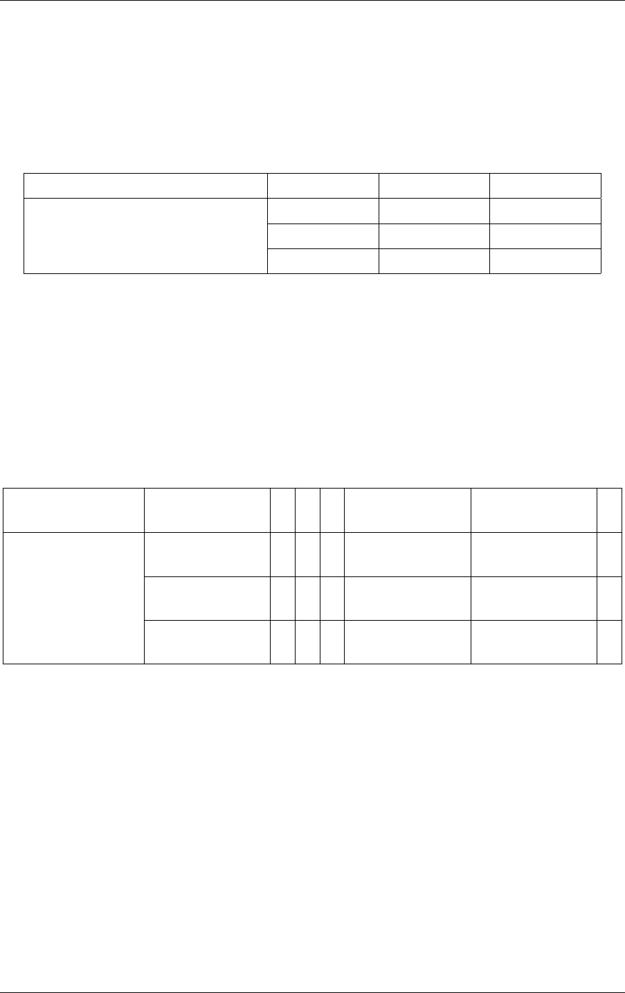
7 Shader binding table 7.3 Acceleration structures
input is the prefix sum of the number of SBT records. Therefore, the computed SBT geometry
acceleration structure index is dependent on the order of the build inputs.
The following example demonstrates a geometry acceleration structure with three build
inputs. Each build input references one SBT record by specifying numSBTRecords=1. When
intersecting geometry at trace time, the SBT geometry acceleration structure index used to
compute the sbtIndex to select the hit group record will be organized as follows:
SBT geometry-AS index 0 1 2
Geometry-AS build input
Build input[0]
Build input[1]
Build input[2]
In this simple example, the index for the build input equals the SBT geometry acceleration
structure index. Hence, whenever a primitive from “Build input [1]” is intersected, the SBT
geometry acceleration structure index is one.
When a single build input references multiple SBT records (for example, to support multiple
materials per geometry), the mapping corresponds to the prefix sum over the number of
referenced SBT records.
For example, consider three build inputs where the first build input references four SBT
records, the second references one SBT record, and the last references two SBT records:
SBT geometry-AS
index
0 1 2 3 4 5 6
Geometry-AS build
input
Build input[0]
numSBTRecords=4
Build input[1]
numSBTRecords=1
Build input[2]
SBTIndexOffset2
These three build inputs result in the following possible SBT geometry acceleration structure
indices when intersecting the corresponding geometry acceleration structure build input:
•
One index in the range of [0,3] if a primitive from “Build input [0]” is intersected
•
Four if a primitive from “Build input [1]” is intersected
•
One index in the range of [5,6] if a primitive from “Build input [2]” is intersected
The per-primitive SBT index offsets, as specified by using sbtIndexOffsetBuffer, are local to
the build input. Hence, per-primitive offsets in the range [0,3] for the build input 0 and in the
range [0,1] for the last build input, map to the SBT geometry acceleration structure index as
follows:
80 NVIDIA OptiX 7.7 ± Programming Guide © 2023 NVIDIA Corporation
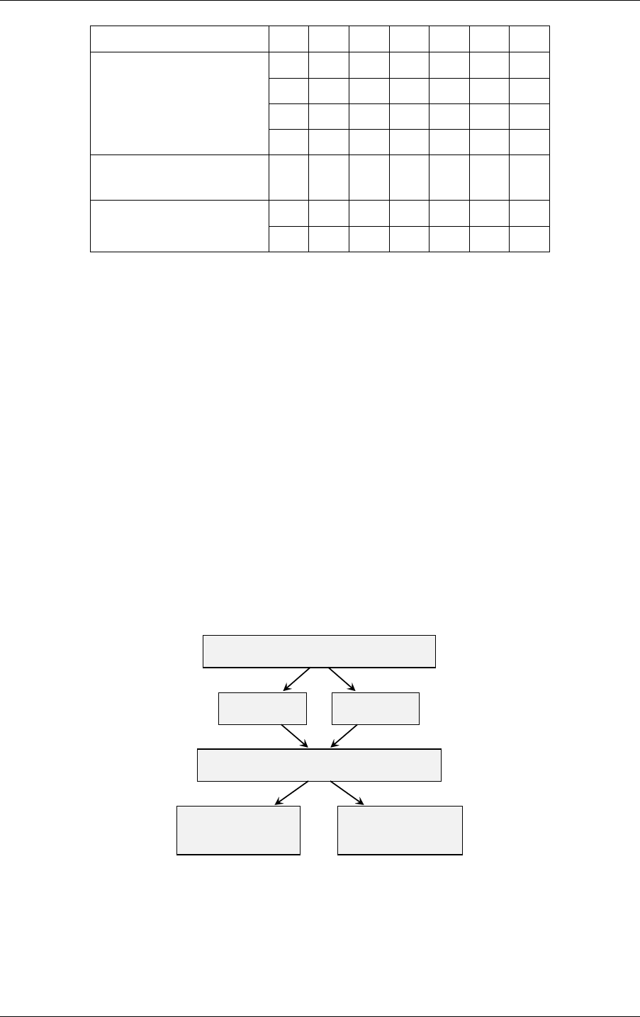
7.3 Acceleration structures 7 Shader binding table
SBT geometry-AS index 0 1 2 3 4 5 6
Build input[0]
SBTIndexOffset:
[0]
[1]
[2]
[3]
Build input[1]
SBTIndexOffset=nullptr
Build input[2]
SBTIndexOffset:
[0]
[1]
Because build input 1 references a single SBT record, a sbtIndexOffsetBuffer does not need to
be specified for the geometry acceleration structure build. See
“Acceleration structures”
(page 79).
7.3.3 SBT trace oset
The optixTrace function takes the parameter SBToffset, allowing for an SBT access shift for
this specific ray. It is required to implement different ray types.
7.3.4 SBT trace stride
The parameter SBTstride, defined as an index offset, is multiplied by optixTrace with the
SBT geometry acceleration structure index. It is required to implement different ray types.
7.3.5 Example SBT for a scene
In this example, a shader binding table implements the program selection for a simple scene
containing one instance acceleration structure and two instances of the same geometry
acceleration structure, where the geometry acceleration structure has two build inputs:
Instance acceleration structure
Instance 0 Instance 1
Geometry acceleration structure
numSBTRecords = 1
Build input 0
numSBTRecords = 2
Build input 1
Fig. 7.1 - Structure of a simple scene
The first build input references a single SBT record, while the second one references two SBT
records. There are two ray types: one for forward path tracing and one for shadow rays (next
event estimation). The two instances of the geometry acceleration structure have different
transforms and SBT offsets to allow for material variation in each instance of the same
geometry acceleration structure. Therefore, the SBT needs to hold two miss records and 12 hit
© 2023 NVIDIA Corporation NVIDIA OptiX 7.7 ± Programming Guide 81
7 Shader binding table 7.3 Acceleration structures
group records (three for the geometry acceleration structure, ×2 for the ray types, ×2 for the
two instances in the instance acceleration structure).
The SBT is structured in the following way:
Raygen Miss instance0.sbtOffset = 0 instance1.sbtOffset = 6
RG0 MS0 MS1 hit0 hit1 hit2 hit3 hit4 hit5 hit6 hit7 hit8 hit9 hit10 hit11
The preceding programs are called for the following combination of geometry and ray types
Instance: 0 0 0 0 0 0 1 1 1 1 1 1
Build input: 0 0 1 1 1 1 0 0 1 1 1 1
SBT index: 0 1 2 3 4 5 6 7 8 9 10 11
SBT instance offset: 0 0 0 0 0 0 6 6 6 6 6 6
SBT geometry-AS index: 0 0 1 1 2 2 0 0 1 1 2 2
Build input SBT index offset: - - 0 0 1 1 - - 0 0 1 1
Trace offset/ray type: 0 1 0 1 0 1 0 1 0 1 0 1 0 1
To trace a ray of type 0 (for example, for path tracing):
Listing 7.3
optixTrace(IAS_handle,
ray_org, ray_dir,
tmin, tmax, time,
visMask, rayFlags,
0,
sbtOset
2,
sbtStride
0,
missSBTIndex
rayPayload0, ...);
Shadow rays need to pass in an adjusted sbtOffset as well as missSBTIndex:
Listing 7.4
optixTrace(IAS_handle,
ray_org, ray_dir,
tmin, tmax, time,
visMask, rayFlags,
1,
sbtOset
2,
sbtStride
1,
missSBTIndex
rayPayload0, ...);
82 NVIDIA OptiX 7.7 ± Programming Guide © 2023 NVIDIA Corporation

7.4 SBT record access on device 7 Shader binding table
Program groups of different types (ray generation, miss, intersection, and so on) do not need
to be adjacent to each other as shown in the example. The pointer to the first SBT record of
each program group type is passed to optixLaunch, as described previously, which allows
for arbitrary spacing in the SBT between the records of different program group types.
7.4 SBT record access on device
To access the SBT data section of the currently running program, request its pointer by using
an API function:
Listing 7.5
CUdeviceptr optixGetSbtDataPointer();
Typically, this pointer is cast to a pointer that represents the layout of the data section. For
example, for a closest hit program, the application gets access to the data associated with the
SBT record that was used to invoke that closest hit program:
Listing 7.6 – Data for closest hit program
struct CHData {
int meshIdx;
Triangle mesh build input index
float3 base_color;
};
CHData* material_info = (CHData*)optixGetSbtDataPointer();
The program is encouraged to rely on the alignment constraints of the SBT data section to
read this data efficiently.
© 2023 NVIDIA Corporation NVIDIA OptiX 7.7 ± Programming Guide 83

7 Shader binding table 7.4 SBT record access on device
84 NVIDIA OptiX 7.7 ± Programming Guide © 2023 NVIDIA Corporation

8 Curves and spheres
8.1 Dierences between curves, spheres, and t riangles
Ray tracing curves or spheres with NVIDIA OptiX is similar to the procedure for ray tracing
triangles; see
“Curve build inputs” (page 24) . The differences between curves, spheres, and
triangles include the following:
•
In the triangle build input, the index buffer is optional. In the curves build input, it is
mandatory. In the spheres build input, it is missing.
•
Each curves build input references just a single SBT record. Unlike triangles or spheres,
there is no per-primitive SBT index. It is still possible to use multiple materials for curves
in the same BVH, by using multiple build inputs, one per material. (Because there is
only one SBT record, the OptixGeometryFlags are specified by only one int, rather than
an array of ints.)
•
There is no preTransform field for curves or spheres. If there were, a nonuniform scale
or shear transformation would yield different results as a pre-transform than as an
instance transform. Nonuniform instance transforms of curves create elliptical cross
sections, while preTransform would still have a circular cross section.
•
Each shader binding table record for curves requires a hit group that uses a built-in
intersection program for curves. In the OptixProgramGroupHitgroup, you must use a
module returned by optixBuiltinISModuleGet() for moduleIS, and nullptr for
entryFunctionNameIS. This also applies to spheres.
•
Curves or spheres must be explicitly enabled in the pipeline to be rendered; triangles
and custom primitives are enabled by default. This is enabled in the
OptixPipelineCompileOptions::usesPrimitiveTypeFlags by setting the relevant
bits from OptixPrimitiveTypeFlags.
Listing 8.1
OptixPipelineCompileOptions pipelineCompileOptions = {};
...
pipelineCompileOptions.usesPrimitiveTypeFlags =
OPTIX_PRIMITIVE_TYPE_FLAGS_TRIANGLE |
OPTIX_PRIMITIVE_TYPE_FLAGS_CUSTOM |
OPTIX_PRIMITIVE_TYPE_FLAGS_ROUND_LINEAR |
OPTIX_PRIMITIVE_TYPE_FLAGS_ROUND_QUADRATIC_BSPLINE |
OPTIX_PRIMITIVE_TYPE_FLAGS_FLAT_QUADRATIC_BSPLINE |
OPTIX_PRIMITIVE_TYPE_FLAGS_ROUND_CUBIC_BSPLINE |
OPTIX_PRIMITIVE_TYPE_FLAGS_ROUND_CATMULLROM |
OPTIX_PRIMITIVE_TYPE_FLAGS_ROUND_CUBIC_BEZIER |
OPTIX_PRIMITIVE_TYPE_FLAGS_SPHERE;
© 2023 NVIDIA Corporation NVIDIA OptiX 7.7 ± Programming Guide 85

8 Curves and spheres 8.3 Curves and the hit program
•
To render motion blur for any primitive, motion blur must be enabled in the pipeline.
But for curves or spheres, motion blur must also be enabled in the built-in intersection
program, by setting the OptixBuiltinISOptions::usesMotionBlur flag. (Note this
flag should only be set to true when using vertex motion blur, not when using motion
transform blur.) The values of the OptixBuiltinISOptions::buildFlags must also
match the corresponding build flags in OptixAccelBuildOptions::buildFlags that
were used for building the acceleration structure, and
OptixBuiltinISOptions::curveEndcapFlags must match
OptixBuildInputCurveArray::endcapFlags.
8.2 Splitting curve segments
NVIDIA OptiX can split curve segments into multiple sub-segments, and bound the
sub-segments separately. This gives faster performance but costs more memory. Splitting can
be controlled via OptixBuildFlags, using OPTIX_BUILD_FLAG_PREFER_FAST_TRACE for a
splitting factor higher than default, and OPTIX_BUILD_FLAG_PREFER_FAST_BUILD for a lower
splitting factor.
Note: Splitting means that the same primitive (the same curve segment) can be hit
multiple times by a ray. Geometry with
OPTIX_GEOMETRY_FLAG_REQUIRE_SINGLE_ANYHIT_CALL set is not split; in this case, each
segment can only be hit once, but a longer curve strand composed of multiple segments
can still be hit more than once.
8.3 Curves and the hit program
In hit programs, non-ribbon curve hits provide a single attribute: the curve parameter (“u”)
within the segment corresponding to the intersection, returned by
optixGetCurveParameter(). When and only when an end cap is hit, the “u” parameter
returned is exactly 0.0 or 1.0. For ribbon hits, two attributes are provided by
optixGetRibbonParameters(). In addition to parameter “u” along the curve axis, parameter
“v” along the width is returned. The range of parameter “v” is -1.0 to 1.0. As with all hit
programs, optixGetRayTmax() returns the ray parameter (“t”), from which the hit point can
be computed, and optixGetPrimitiveIndex() returns the segment’s primitive index. To
maximize performance, no other geometry attributes are passed or precomputed. Instead, the
program must compute whatever curve geometry it requires using the vertex data. For
ribbons, you can compute the geometric normal by passing in the primitive index and the
ribbon parameters to optixGetRibbonNormal().
optixGetRibbonNormal
To make vertex data available to your OptiX shaders (for example your closest-hit program),
the geometry acceleration structure build flag must include
OPTIX_BUILD_FLAG_ALLOW_RANDOM_VERTEX_ACCESS. (See
“Build flags” (page 27).) To fetch
the vertex positions and radius values for the segment, pass the primitive index to the
function appropriate for the curve type:
optixGetLinearCurveVertexData
optixGetQuadraticBSplineVertexData
optixGetCubicBSplineVertexData
optixGetCatmullRomVertexData
86 NVIDIA OptiX 7.7 ± Programming Guide © 2023 NVIDIA Corporation
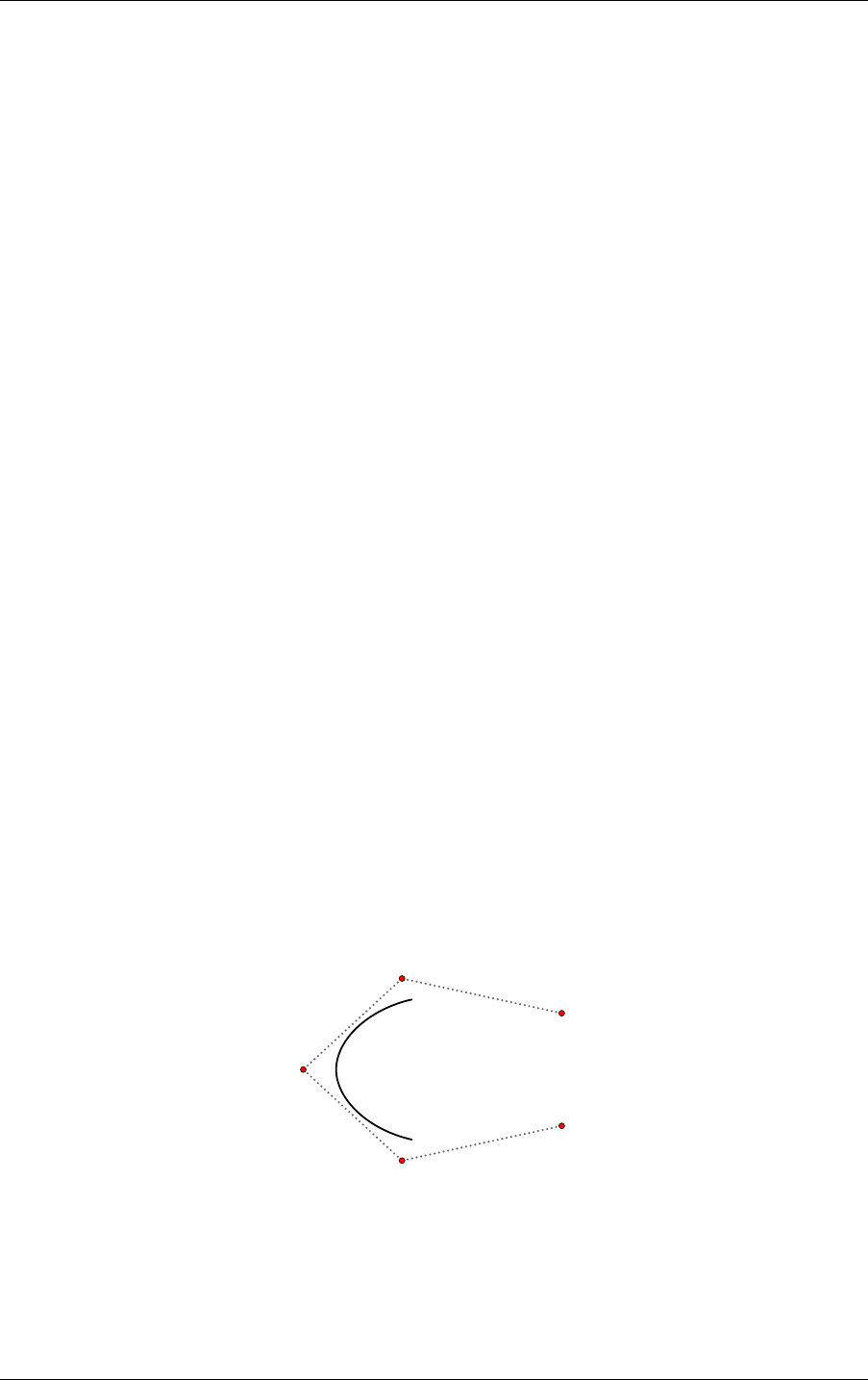
8.4 Spheres and the hit program 8 Curves and spheres
optixGetCubicBezierVertexData
optixGetRibbonVertexData
Sample code is provided to interpolate the curve points and radii, and to compute tangents,
normals, and derivatives; see header file SDK/cuda/curve.h. A single hit program can (and
should) handle multiple curve primitive types by checking the value of
optixGetPrimitiveType(). For example, see optixHair.cu in the optixHair code sample.
The optixGetCurveParameter and optixGetRibbonParameters functions return the “u”
parameter value relative to a single polynomial segment of the curve. If needed, the hit
program can map this to the parameter value relative to the entire multi-segment strand. For
instance, this can be used to interpolate between two colors specified at the root and tip of a
hair. This segment-to-strand mapping is the application’s responsibility; see the optixHair
code sample for an example implementation.
8.4 Spheres and t he hit program
Hit programs for spheres report a maximum of two intersections of a ray with a sphere,
ordered along the ray. The second intersection is represented by the single attribute of the
sphere hit: the ray parameter of the second hit with the sphere, if a second hit exists,
otherwise 0. The function optixGetRayTmax() returns the ray parameter (“t”), from which the
first hit point can be computed, together with the hit type. The function
optixGetPrimitiveIndex() returns the sphere’s primitive index. Similar to curves, no other
geometry attributes are passed or precomputed. Instead, the program must compute
whatever sphere geometry it requires (surface normals, etc.) using the vertex data.
To make vertex data available to OptiX shaders (for example the closest-hit program), the
build flag of the geometry acceleration structure must include
OPTIX_BUILD_FLAG_ALLOW_RANDOM_VERTEX_ACCESS. (See
“Build flags” (page 27).) By
including this flag, the function optixGetSphereData can acquire the vertex positions and
radius values for the sphere.
8.5 Interpolating curve endpoints
A B-spline curve typically does not interpolate (that is, does not touch) its control points. In
particular, in contrast to a Bézier curve, it does not reach as far as its first and last control
points:
Fig. 8.1 - The curve does not reach
the first and last control points
If desired, the application can modify the control point sequence to interpolate these points,
by adding an additional control point at each end:
© 2023 NVIDIA Corporation NVIDIA OptiX 7.7 ± Programming Guide 87
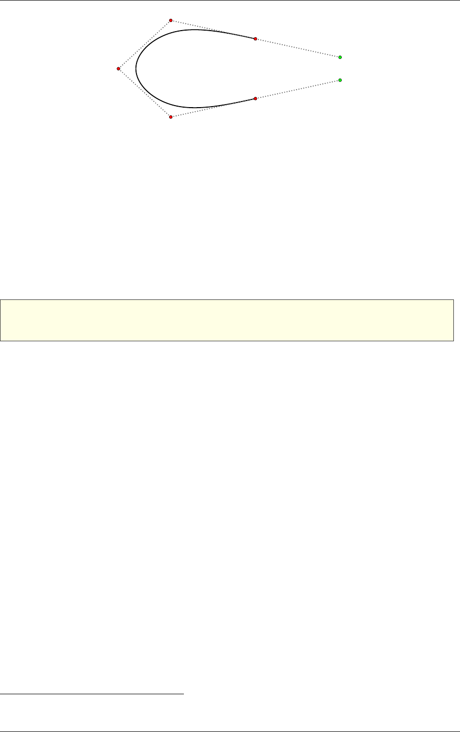
8 Curves and spheres 8.7 Limitations
Fig. 8.2 - Adding points (in green) to extend the curve
Following the Universal Scene Description documentation,
1
let’s call these “phantom” points,
resulting in “pinned” curves. A phantom point is constructed by reflecting through the
endpoint the point that preceded it. Given control points p
1
, p
2
...p
n
, the phantom points can
be defined geometrically by:
p
0
= p
1
+ (p
1
− p
2
)
p
n+1
= p
n
+ (p
n
− p
n−1
)
It is also possible to interpolate endpoints by repeating them. For cubic B-spline curves, a
control point that is repeated 3 times will be interpolated. OptiX allows this, but the phantom
point method is preferred, as it is numerically more stable, and permits control of curvature.
Note: The additional points must be added to the build input by the application. These
points are not added by NVIDIA OptiX itself.
8.6 B ack-face culling
The tube of a curve primitive is considered hollow, and back faces are culled. Thus if a ray
starts inside a curve primitive (inside the tube), it will not hit that primitive. This is
convenient for secondary rays and for transparency. However, see
“Limitations” (page 88)
below.
Back faces of spheres are not culled. A ray is allowed to start inside the sphere. In this case,
the reported (single) hit would be a back-face hit. Functions optixIsBackFaceHit or
optixIsFrontFaceHit can be used to determine which face has been hit. For secondary rays,
it can be useful to ignore back-face hits.
8.7 Limitations
There are some caveats to be aware of when using curves and curve hit programs.
Multiple hits
For a ray that intersects a single curve segment more than once, NVIDIA OptiX does not
guarantee that all intersections will be reported as hits. In particular, the any-hit program
will in general not be called more than once for a given segment. To implement
transparency, the alternative approach to using an any-hit program is to use closest-hit
and relaunch a continuation ray from each hit.
Back-face culling
1. https://graphics.pixar.com/usd/docs/api/class_usd_geom_basis_curves.html#UsdGeomBasisCurves_
Segment
88 NVIDIA OptiX 7.7 ± Programming Guide © 2023 NVIDIA Corporation

8.7 Limitations 8 Curves and spheres
While the tube is mostly hollow, in the current implementation a ray can hit an internal
endcap, meaning an endcap between two segments of a strand. For typical curves that
are much longer than they are wide, this is often not noticeable. To avoid hitting internal
endcaps, adjust secondary rays to launch from outside the tube.
Triple control points
As noted in
“Interpolating curve endpoints” (page 87), duplicating control points is
possible in NVIDIA OptiX, but the use of phantom points is preferred. Duplicating the
ending control points is numerically challenging (the derivative is zero) and the first
segment is forced to be straight.
Convoluted cases
Curves for hair, fur, cloth fibers, etc., are typically thin with relatively gentle curvature. It
is possible to construct curve segments with tight curvature (relative to width),
self-intersections, or rapidly varying radii that will exhibit artifacts, particularly if
rendered up close. In many cases, these can be remedied by splitting the segment into 3
smaller segments.
Ribbon basis type and representation
Ribbons are oriented curves, where the basis type is restricted to uniform quadratic
B-splines. As described in
“Curve build inputs” (page 24), it is assumed that the
segments of a ribbon strand have overlapping control points. The first index of a ribbon
build input should be 0; there are no unused control points at the beginning of the vertex
data.
Ribbons with user-specified normals (orientations)
Ribbons can be used without any specified orientations. The orientation is computed
automatically from the shape of the curve axis, taking its tangent along the strand into
account. For many applications, such as modeling grass, this computation produces the
intended orientations and should be the preferred method. Alternatively, normals can be
provided for orienting the ribbons. The normals are not control points of a quadratic
B-spline, but are linearly interpolated along the segment. The normals need to fit the
curve geometry sufficiently, otherwise the connections between segments may not be
smooth. Non-smooth segment borders may also show up for straight ribbon strands.
These can be addressed by slightly perturbing the control points of the strand.
© 2023 NVIDIA Corporation NVIDIA OptiX 7.7 ± Programming Guide 89

8 Curves and spheres 8.7 Limitations
90 NVIDIA OptiX 7.7 ± Programming Guide © 2023 NVIDIA Corporation

9 Ray generation launches
The API function described in this section is:
optixLaunch
A ray generation launch is the primary workhorse of the NVIDIA OptiX API. A launch
invokes a 1D, 2D or 3D array of threads on the device and invokes ray generation programs
for each thread. When the ray generation program invokes optixTrace, other programs are
invoked to execute traversal, intersection, any-hit, closest-hit, miss and exception programs
until the invocations are complete.
A pipeline requires device-side memory for each launch. This space is allocated and managed
by the API. Because launch resources may be shared between pipelines, they are only
guaranteed to be freed when the OptixDeviceContext is destroyed.
To initiate a pipeline launch, use the optixLaunch function. All launches are asynchronous,
using CUDA streams. When it is necessary to implement synchronization, use the
mechanisms provided by CUDA streams and events.
In addition to the pipeline object, the CUDA stream, and the launch state, it is necessary to
provide information about the SBT layout, including: This includes:
•
The base addresses for sections of the SBT that hold the records of different types
•
The stride, in bytes, along with the maximum valid index for arrays of SBT records. The
stride is used to calculate the SBT address for a record based on a given index. (See
“Layout” (page 78).)
The value of the pipeline launch parameter is specified by the
pipelineLaunchParamsVariableName field of the OptixPipelineCompileOptions struct. It
is determined at launch with a CUdeviceptr parameter, named pipelineParams, that is
provided to optixLaunch. Note the following restrictions:
•
If the size specified by the pipelineParamsSize argument of optixLaunch is smaller
than the size of the variable specified by the modules, the non-overlapping values of the
parameter will be undefined.
•
If the size is larger, an error will occur.
(See
“Pipeline launch parameter” (page 66).)
The kernel creates a copy of pipelineParams before the launch, so the kernel is allowed to
modify pipelineParams values during the launch. This means that subsequent launches can
run with modified pipeline parameter values. Users cannot synchronize with this copy
between the invocation of optixLaunch and the start of the kernel.
© 2023 NVIDIA Corporation NVIDIA OptiX 7.7 ± Programming Guide 91

9 Ray generation launches
Note: Concurrent launches with different values for pipelineParams in the same
pipeline triggers serialization of the launches. Concurrency requires a separate pipeline
for each concurrent launch.
The dimensions of a launch must also be specified. If one-dimensional launches are required,
use the width as the dimension of the launch and set both a height and a depth of 1. If
two-dimensional launches are required, set the width and the height as the dimension of the
launch and set a depth of 1.
Dimension Width Height Depth
1D width 1 1
2D width height 1
3D width height depth
Specifying different dimensions for a launch
For example:
Listing 9.1
CUstream stream = nullptr;
cuStreamCreate(&stream);
CUdeviceptr raygenRecord, hitgroupRecords;
...
Generate acceleration structures and SBT records
unsigned int width = ...;
unsigned int height = ...;
unsigned int depth = ...;
OptixShaderBindingTable sbt = {};
sbt.raygenRecord = raygenRecord;
sbt.hitgroupRecords = hitgroupRecords;
sbt.hitgroupRecordStrideInBytes = sizeof(HitGroupRecord);
sbt.hitgroupRecordCount = numHitGroupRecords;
MyPipelineParams pipelineParams = ...;
CUdeviceptr d_pipelineParams = 0;
...
Allocate and copy the params to the device
optixLaunch(pipeline, stream,
d_pipelineParams, sizeof(MyPipelineParams),
&sbt, width, height, depth);
92 NVIDIA OptiX 7.7 ± Programming Guide © 2023 NVIDIA Corporation

10 Limits
The previous chapters described properties that have an upper limit lower than the limit
implied by the data type of the property. The values of these limits depend on the GPU
generation for which the device context is created. These values can be queried at runtime
using optixDeviceContextGetProperty.
Limit values may change from one OptiX SDK version to the next but not internally with
updated NVIDIA drivers. Updated drivers use the limit values of the SDK version employed
during application compilation as well as the GPU generation. The following table lists the
NVIDIA OptiX limit values for the currently supported GPU generations, including Turing:
Type of limit Limit
non-RTX cards
RTX-enabled Turing
Ampere
Ada Lovelace
Acceleration structure Maximum number of primitives per geometry
acceleration structure including motion keys
2
29
2
29
2
29
2
29
Maximum number of referenced SBT records per
geometry acceleration structure
2
24
2
24
2
24
2
24
Maximum number of instances per instance acceleration
structure
2
28
* 2
28
* 2
28
* 2
28
*
Number of bits for SBT offset 28* 28* 28* 28*
Number of bits for user ID 28* 28* 28* 28*
Number of bits for visibility mask 8 8 8 8
Pipeline Maximum trace (recursion) depth 31 31 31 31
Maximum traversable graph depth 31 31 31 31
Device functions Number of bits for optixTrace – visibilityMask 8 8 8 8
Number of bits for optixTrace – SBTstride 4 4 4 4
Number of bits for optixTrace – SBToffset 4 4 4 4
Number of bits for optixReportIntersection –
hitKind
7 7 7 7
Hardware version RT Cores version (read as x.x) 00 10 20 30
Support for displaced micro-meshes - x x x
NVIDIA OptiX limits
Note: In the table, values marked with * were raised beginning in NVIDIA OptiX
version 7.1. For code compiled with OptiX SDK version 7.0, the limit is 24.
© 2023 NVIDIA Corporation NVIDIA OptiX 7.7 ± Programming Guide 93

10 Limits
For the instance properties SBT offset, user ID, and visibility mask, the higher bits of the 32-bit
struct member must be set to zero. In case of the device functions, any bits higher than those
specified in the table are ignored. Limits for device functions cannot be queried at runtime.
For more information on CUDA limits and supported features, see
Appendix K: Compute
Capabilities
1
in the Cuda Toolkit documentation. However, note that the upper limit for the
size of an OptiX launch requires width × height × depth ≤ 2
30
.
1. https://docs.nvidia.com/cuda/cuda-c-programming-guide/index.html#compute-capabilities
94 NVIDIA OptiX 7.7 ± Programming Guide © 2023 NVIDIA Corporation

11 Device-side functions
The NVIDIA OptiX device runtime provides functions to set and get the ray tracing state and
to trace new rays from within user programs. The following functions are available in all
program types:
1
optixGetTransformTypeFromHandle
optixGetInstanceChildFromHandle
optixGetInstanceIdFromHandle
optixGetInstanceTransformFromHandle
optixGetInstanceInverseTransformFromHandle
optixGetStaticTransformFromHandle
optixGetMatrixMotionTransformFromHandle
optixGetSRTMotionTransformFromHandle
optixGetGASMotionTimeBegin
optixGetGASMotionTimeEnd
optixGetGASMotionStepCount
optixGetPrimitiveType(hitKind)
optixIsFrontFaceHit(hitKind)
optixIsBackFaceHit(hitKind)
optixGetTriangleVertexData
optixGetLinearCurveVertexData
optixGetQuadraticBSplineVertexData
optixGetCubicBSplineVertexData
optixGetCatmullRomVertexData
optixGetCubicBezierVertexData
optixGetRibbonVertexData
optixGetRibbonNormal
optixGetSphereData
optixGetInstanceTraversableFromIAS
optixGetLaunchIndex
optixGetLaunchDimensions
Other functions are available only in specific program types. The following table identifies
the program types within which the OptiX device functions are valid.
1. The abbreviation “GAS” is used for geometry acceleration structures in function names.
© 2023 NVIDIA Corporation NVIDIA OptiX 7.7 ± Programming Guide 95
11 Device-side functions
Device function
ray generation
intersection
any hit
closest hit
miss
exception
direct callable
continuation callable
optix enabled
optixTrace
optixContinuationCall
✓ ✓ ✓ ✓
optixGetSbtDataPointer ✓ ✓ ✓ ✓ ✓ ✓ ✓ ✓
optixSetPayload_0 ... optixSetPayload_31
optixGetPayload_0 ... optixGetPayload_31
optixSetPayloadTypes
optixGetWorldRayOrigin
optixGetWorldRayDirection
optixGetRayTmin
optixGetRayTmax
optixGetRayTime
optixGetRayFlags
optixGetRayVisibilityMask
✓ ✓ ✓ ✓
optixGetObjectRayOrigin
optixGetObjectRayDirection
✓ ✓
optixGetTransformListSize
optixGetTransformListHandle
optixGetSbtGASIndex
✓ ✓ ✓ ✓
optixGetWorldToObjectTransformMatrix
optixGetObjectToWorldTransformMatrix
optixTransformPointFromWorldToObjectSpace
optixTransformPointFromObjectToWorldSpace
optixTransformVectorFromWorldToObjectSpace
optixTransformVectorFromObjectToWorldSpace
optixTransformNormalFromWorldToObjectSpace
optixTransformNormalFromObjectToWorldSpace
optixGetGASTraversableHandle
optixGetPrimitiveIndex
optixGetInstanceId
optixGetInstanceIndex
✓ ✓ ✓
optixGetHitKind
optixGetPrimitiveType
optixIsFrontFaceHit
optixIsBackFaceHit
optixIsTriangleHit (header function)
optixIsTriangleFrontFaceHit (header function)
optixIsTriangleBackFaceHit (header function)
optixIsDisplacedMicromeshTriangleHit
(header function)
optixIsDisplacedMicromeshTriangleFrontFaceHit
(header function)
optixIsDisplacedMicromeshTriangleBackFaceHit
(header function)
optixGetTriangleBarycentrics
optixGetMicroTriangleVertexData
optixGetMicroTriangleBarycentricsData
optixGetCurveParameter
optixGetAttribute_0 ... optixGetAttribute_7
✓ ✓
optixReportIntersection ✓
optixTerminateRay
optixIgnoreIntersection
✓
96 NVIDIA OptiX 7.7 ± Programming Guide © 2023 NVIDIA Corporation
11.1 Launch index 11 Device-side functions
Device function
ray generation
intersection
any hit
closest hit
miss
exception
direct callable
continuation callable
optix enabled
optixDirectCall
optixThrowException
✓ ✓ ✓ ✓ ✓ ✓ ✓ ✓
optixGetExceptionCode
optixGetExceptionInvalidTraversable
optixGetExceptionInvalidSbtOffset
optixGetExceptionInvalidRay
optixGetExceptionParameterMismatch
optixGetExceptionLineInfo
optixGetExceptionDetail_0 ...
optixGetExceptionDetail_7
✓
Any function in the module that calls an NVIDIA OptiX device-side function is inlined into
the caller (with the exceptions noted below). This process is repeated until only the outermost
function contains these function calls.
For example, consider a closest-hit program that calls a function called computeValue, which
calls computeDeeperValue, which itself calls optixGetTriangleBarycentrics. The inlining
process inlines the body of computeDeeperValue into computeValue, which in turn, is
inlined into the closest-hit program. Recursive functions that call device-side API functions
will generate a compilation error.
The following functions do not trigger inlining:
optixTexFootprint2D
optixGetInstanceChildFromHandle
optixTexFootprint2DGrad
optixTexFootprint2DLod
11.1 Launch index
The launch index identifies the current thread, within the launch dimensions specified by
optixLaunch on the host. The launch index is available in all programs.
Listing 11.1
uint3 optixGetLaunchIndex();
Typically, the ray generation program is only launched once per launch index.
In contrast to the CUDA programming model, program execution of neighboring launch
indices is not necessarily done within the same warp or block, so the application must not
rely on the locality of launch indices.
11.2 Trace
The optixTrace function initiates a ray tracing query starting with the given traversable and
the provided ray origin and direction. If the given OptixTraversableHandle is null, only the
miss program is invoked.
© 2023 NVIDIA Corporation NVIDIA OptiX 7.7 ± Programming Guide 97

11 Device-side functions 11.2 Trace
The tmin and tmax arguments set the extent associated with the current ray. Any reported
hits with hitT outside of this range are ignored. The tmin value must be equal or greater than
zero. The optixTrace function’s behavior is undefined for negative tmin values.
An arbitrary payload is associated with each ray that is initialized with this call; the payload
is passed to all the intersection, any-hit, closest-hit and miss programs that are executed
during this invocation of trace. The payload can be read and written by each program using
the pairs of optixGetPayload and optixSetPayload functions (for example,
optixGetPayload_0 and optixSetPayload_0). The payload is subsequently passed back to
the caller of optixTrace and follows a copy-in/copy-out semantic. See
“Payload” (page 115).
The rayTime argument sets the time allocated for motion-aware traversal and material
evaluation. If motion is not enabled in the pipeline compile options, the ray time is ignored
and removed by the compiler. To request the ray time, use the optixGetRayTime function. In
a pipeline without motion, optixGetRayTime always returns 0.
The rayFlags argument can represent a combination of OptixRayFlags. The following flags
are supported. Illegal combinations are noted.
OPTIX_RAY_FLAG_NONE
No change from the behavior configured for the individual acceleration structure.
OPTIX_RAY_FLAG_DISABLE_ANYHIT
Disables any-hit programs for the ray. Overrides potential instance flag
OPTIX_INSTANCE_FLAG_ENFORCE_ANYHIT when intersecting instances. This flag is
mutually exclusive with OPTIX_RAY_FLAG_ENFORCE_ANYHIT,
OPTIX_RAY_FLAG_CULL_DISABLED_ANYHIT, OPTIX_RAY_FLAG_CULL_ENFORCED_ANYHIT.
OPTIX_RAY_FLAG_ENFORCE_ANYHIT
Forces any-hit program execution for the ray. Overrides
OPTIX_GEOMETRY_FLAG_DISABLE_ANYHIT and OPTIX_INSTANCE_FLAG_DISABLE_ANYHIT.
OPTIX_RAY_FLAG_TERMINATE_ON_FIRST_HIT
Terminates the ray after the first hit and executes the closest-hit program of that hit.
OPTIX_RAY_FLAG_DISABLE_CLOSESTHIT
Disables closest-hit programs for the ray, but still executes the miss program in case of a
miss.
OPTIX_RAY_FLAG_CULL_BACK_FACING_TRIANGLES
Prevents intersection of triangle back faces (respects a possible face change due to
instance flag OPTIX_INSTANCE_FLAG_FLIP_TRIANGLE_FACING). This flag is mutually
exclusive with OPTIX_RAY_FLAG_CULL_FRONT_FACING_TRIANGLES.
OPTIX_RAY_FLAG_CULL_FRONT_FACING_TRIANGLES
Prevents intersection of triangle front faces (respects a possible face change due to
instance flag OPTIX_INSTANCE_FLAG_FLIP_TRIANGLE_FACING). This flag is mutually
exclusive with OPTIX_RAY_FLAG_CULL_BACK_FACING_TRIANGLES.
OPTIX_RAY_FLAG_CULL_DISABLED_ANYHIT
Prevents intersection of geometry which disables any-hit programs (due to setting
geometry flag OPTIX_GEOMETRY_FLAG_DISABLE_ANYHIT or instance flag
OPTIX_INSTANCE_FLAG_DISABLE_ANYHIT). This flag is mutually exclusive with
98 NVIDIA OptiX 7.7 ± Programming Guide © 2023 NVIDIA Corporation

11.3 Payload access 11 Device-side functions
OPTIX_RAY_FLAG_CULL_ENFORCED_ANYHIT, OPTIX_RAY_FLAG_ENFORCE_ANYHIT,
OPTIX_RAY_FLAG_DISABLE_ANYHIT.
OPTIX_RAY_FLAG_CULL_ENFORCED_ANYHIT
Prevents intersection of geometry which have an enabled any-hit program (due to not
setting geometry flag OPTIX_GEOMETRY_FLAG_DISABLE_ANYHIT or setting instance flag
OPTIX_INSTANCE_FLAG_ENFORCE_ANYHIT). This flag is mutually exclusive with
OPTIX_RAY_FLAG_CULL_DISABLED_ANYHIT, OPTIX_RAY_FLAG_ENFORCE_ANYHIT,
OPTIX_RAY_FLAG_DISABLE_ANYHIT.
Ray flags modify traversal behavior. For example, setting ray flag
OPTIX_RAY_FLAG_TERMINATE_ON_FIRST_HIT causes the very first hit (that is not ignored in
any-hit) to abort further traversal, defining it as the closest hit. This particular flag can be
useful for shadow rays to allow for the early termination of a traversal without the need for a
special any-hit program that calls optixTerminateRay.
The visibility mask controls intersection against configurable masks of instances. (See
“Instance build inputs” (page 26).) Intersections are computed if there is at least one matching
bit in both masks. The same limit applies in the number of available bits as for the instance
visibility mask. See “Limits” (page 93).
The SBT offset and stride adjust the SBT indexing when selecting the SBT record for a ray
intersection. Like the visibility mask, both parameters are limited. See
“Limits” (page 93) and
“Acceleration structures” (page 7).
The specified miss SBT index is used to identify the program that is invoked on a miss. (See
“Layout” (page 78).) The argument must be a valid index for a SBT record for a miss program.
Listing 11.2
__device__ void optixTrace(OptixTraversableHandle handle,
float3 rayOrigin,
float3 rayDirection,
float tmin,
float tmax,
float rayTime,
OptixVisibilityMask visibilityMask,
unsigned int rayFlags,
unsigned int SBToffset,
unsigned int SBTstride,
unsigned int missSBTIndex,
unsigned int& p0,
...
unsigned int& p7);
11.3 Payload access
In intersection, any-hit, closest-hit, and miss programs, the payload is used to communicate
values from the optixTrace that initiates the traversal, to and from other programs in the
traversal, and back to the caller of optixTrace. There are up to thirty-two 32-bit payload
values available. Getting and setting the thirty-two payload values use functions whose
names end with a payload index. For example, payload 0 is set and accessed by these two
functions:
© 2023 NVIDIA Corporation NVIDIA OptiX 7.7 ± Programming Guide 99

11 Device-side functions 11.4 Reporting intersections and attribute access
Listing 11.3
__device__ void optixSetPayload_0(unsigned int p);
__device__ unsigned int optixGetPayload_0();
If the user configured payload types with the
OptixModuleCompileOptions::numPayloadTypes and
OptixModuleCompileOptions::payloadTypes compile options, the optixSetPayloadTypes
function associates a program with particular payload types. When used, this function must
be called unconditionally at the top of the program. See
“Payload” (page 115).
Listing 11.4
__device__ void optixSetPayloadTypes(unsigned int typeMask);
11.4 Reporting intersections and attribute access
To report an intersection with the current traversable, the intersection program can use the
optixReportIntersection function. The hitKind of the given intersection is communicated
to the associated any-hit and closest-hit program and allows the any-hit and closest-hit
programs to customize how the attributes should be interpreted. The lowest 7 bits of the
hitKind are interpreted; values [128, 255] are reserved for internal use.
Up to eight 32-bit primitive attribute values are available. Intersection programs write the
attributes when reporting an intersection using optixReportIntersection. Then closest-hit
and any-hit programs are able to read these attributes. For example:
Listing 11.5
__device__ bool optixReportIntersection(
float hitT,
unsigned int hitKind,
unsigned int a0, ... , unsigned int a7);
__device__ unsigned int optixGetAttribute_0();
To reject a reported intersection in an any-hit program, an application calls
optixIgnoreIntersection. The closest-hit program is called for the closest accepted
intersection with the attributes reported for that intersection. An any-hit program may not be
called for all possible hits along the ray. When an intersection is accepted (not discarded by
optixIgnoreIntersection), the interval for intersection and traversal is updated. Further
intersections outside the new interval are not performed.
Although the type of the attributes is exclusively integer data, it is expected that users will
wrap one or more of these data types into more readable data structures using
__int_as_float and __float_as_int, or other data types where necessary.
Triangle intersections return two attributes, the barycentric coordinates (u,v) of the hit, which
may be read with the convenience function optixGetTriangleBarycentrics. Analoguously,
ribbon primitive intersections return two attributes, the coordinates (u,v) of the hit with the
ribbon segment, which may be read by optixGetRibbonParameters. Other curve primitive
100 NVIDIA OptiX 7.7 ± Programming Guide © 2023 NVIDIA Corporation

11.5 Ray information 11 Device-side functions
intersections return one attribute, the curve parameter (u) within the polynomial curve
segment, which may be read with the convenience function optixGetCurveParameter.
Sphere intersections return one attribute, the ray parameter of the second intersection, or 0 if
it doesn’t exist.
No more than eight values can be used for attributes. Unlike the ray payload that can contain
pointers to local memory, attributes should not contain pointers to local memory. This
memory may not be available in the closest-hit or intersection programs when the attributes
are consumed. More sophisticated attributes are probably better handled in the closest-hit
program. There are generally better memory bandwidth savings by deferring certain
calculations to the closest-hit program or reloading values once in the closest-hit program.
11.5 Ray information
To query the properties of the currently active ray, use the following functions:
optixGetWorldRayOrigin / optixGetWorldRayDirection
Returns the ray’s origin and direction passed into optixTrace. It may be more expensive
to call these functions during traversal (that is, in intersection or any-hit) than their object
space counterparts.
optixGetObjectRayOrigin / optixGetObjectRayDirection
Returns the object space ray direction or origin based based on the current transformation
stack. These functions are only available in intersection and any-hit programs.
optixGetRayTmin
Returns the minimum extent associated with the current ray. This is the tmin value
passed into optixTrace.
optixGetRayTmax
Returns the maximum extent associated with the current ray. Note the following:
•
In intersection and closest-hit programs, this is the smallest reported hitT or if no
intersection has been recorded yet the tmax that was passed into optixTrace.
•
In any-hit programs, this returns the hitT value as passed into
optixReportIntersection.
•
In miss programs, the return value is the tmax that was passed into optixTrace.
optixGetRayTime
Returns the time value passed into optixTrace. Returns 0 if motion is disabled in the
pipeline.
optixGetRayFlags
Returns the ray flags passed into optixTrace.
optixGetRayVisibilityMask
Returns the visibility mask passed into optixTrace.
Note: In ray-generation and exception programs, these functions are not supported
because there is no currently active ray.
© 2023 NVIDIA Corporation NVIDIA OptiX 7.7 ± Programming Guide 101

11 Device-side functions 11.7 Intersection information
11.6 Undened values
Advanced application writers seeking more fine-grained control over register usage may
want to reduce total register use in heavy intersect and any-hit programs by writing an
unknown value to payload slots not used during traversal. NVIDIA OptiX provides the
following function to make this straightforward:
Listing 11.6
__device__ unsigned int optixUndefinedValue();
11.7 Intersection information
The primitive index of the current intersection point can be queried using
optixGetPrimitiveIndex. The primitive index is local to its build input.
The SBT index of the current intersection point can be queried using optixGetSbtGASIndex.
The SBT index is local to its build input. (See
“Shader binding table” (page 77).)
The application can query the 8-bit hit kind by using optixGetHitKind. The hit kind is
analyzed by calling optixGetPrimitiveType, which tells whether a custom primitive,
built-in triangle, built-in sphere, or built-in curve primitive was hit, as well as whether the
curve was linear, quadratic or cubic B-spline, a cubic Bézier, or a Catmull-Rom spline. For
built-in primitives, optixIsFrontFaceHit and optixIsBackFaceHit tell whether the ray hit
a front or back face of the primitive. The front face of a built-in triangle primitive is defined
by the counter-clockwise winding of the vertices. For custom primitives, the hit kind is the
value reported by optixReportIntersection when it was called in the intersection.
The default counter-clockwise winding that defines the front face can be changed to
clockwise winding by setting the OPTIX_INSTANCE_FLAG_FLIP_TRIANGLE_FACING instance
flag. The value of this flag in an instance overrides the flag’s value that may have been set
during the traversal of the acceleration structures of parent instances. (For a description of
instance flags, see
“Instance build inputs” (page 26).)
Note: It is generally more efficient to have one hit shader handle multiple primitive
types (by switching on the value of optixGetPrimitiveType), rather than have several
hit shaders that implement the same ray behavior but differ only in the type of geometry
they expect.
For triangle hits, there are several notational shortcuts. The hit kind is either
OPTIX_HIT_KIND_TRIANGLE_FRONT_FACE or OPTIX_HIT_KIND_TRIANGLE_BACK_FACE,
depending on whether the ray came from the front or back of the triangle.
The device functions optixIsTriangleHit, optixIsTriangleFrontFaceHit, and
optixIsTriangleBackFaceHit may also be used.
The functions optixGetPrimitiveType, optixIsFrontFaceHit, and optixIsBackFaceHit
each have two forms. Without an argument, they analyze the current ray intersection; this
form can only be used in a closest-hit or any-hit program. Or, an explicit hit kind argument
may be used; this form can be called from any type of program.
When traversing a scene with instances, that is, a scene containing instance acceleration
structure objects, two properties of the most recently visited instance can be queried in
intersection and any-hit programs. In the case of closest-hit programs, the properties
102 NVIDIA OptiX 7.7 ± Programming Guide © 2023 NVIDIA Corporation

11.8 SBT record data 11 Device-side functions
reference the instance most recently visited when the hit was recorded with
optixReportIntersection. Using optixGetInstanceId the value supplied to the
OptixInstance::instanceId can be retrieved. Using optixGetInstanceIndex the
zero-based index within the instance acceleration structure’s instances associated with the
instance is returned. If no instance has been visited between the geometry primitive and the
target for optixTrace, optixGetInstanceId returns ˜0u (the bitwise complement of a
unsigned int zero) and optixGetInstanceIndex returns an unsigned int zero.
11.8 SBT record data
The data section of the current SBT record can be accessed using optixGetSbtDataPointer.
It returns a pointer to the data, omitting the header of the SBT record (see
“Shader binding
table”
(page 77)).
11.9 Vertex random access
Triangle vertices are baked into the triangle data structure of the geometry acceleration
structure. When a triangle geometry acceleration structure is built with the
OPTIX_BUILD_FLAG_ALLOW_RANDOM_VERTEX_ACCESS flag set, the application can query in
object space the triangle vertex data of any triangle in the geometry acceleration structure.
Because the geometry acceleration structure contains the triangle data, the application can
safely release its own triangle data buffers on the device, thereby lowering overall memory
usage.
The function optixGetTriangleVertexData returns the three triangle vertices at the
rayTime passed in. Motion interpolation is performed if motion is enabled on the geometry
acceleration structure and pipeline.
Listing 11.7
void optixGetTriangleVertexData(
OptixTraversableHandle gas,
unsigned int primIdx,
unsigned int sbtGasIdx,
float rayTime,
float3 data[3]);
The user can call functions optixGetGASTraversableHandle, optixGetPrimitiveIndex,
optixGetSbtGASIndex and optixGetRayTime to obtain the geometry acceleration structure
traversable handle, primitive index, geometry acceleration structure local SBT index and
motion time associated with an intersection in the closest-hit and any-hit programs. The
function optixGetTriangleVertexData also performs motion vertex interpolation for
triangle position data.
© 2023 NVIDIA Corporation NVIDIA OptiX 7.7 ± Programming Guide 103

11 Device-side functions 11.9 Vertex random access
For example:
Listing 11.8
OptixTraversableHandle gas = optixGetGASTraversableHandle();
unsigned int primIdx = optixGetPrimitiveIndex();
unsigned int sbtIdx = optixGetSbtGASIndex();
float time = optixGetRayTime();
float3 data[3];
optixGetTriangleVertexData(gas, primIdx, sbtIdx, time, data);
NVIDIA OptiX may remove degenerate (unintersectable) triangles from the acceleration
structure during construction. Calling optixGetTriangleVertexData on a degenerate
triangle returns NaN as triangle data, not the original triangle vertices.
The potential decompression step of triangle data may come with significant runtime
overhead. Enabling random access may cause the geometry acceleration structure to use
slightly more memory.
Care has to be taken if optixGetTriangleVertexData is used with a primitive index other
than the value returned by optixGetPrimitiveIndex. optixGetTriangleVertexData
expects a local primitive index corresponding to the build input / sbtGASIndex plus the
primitive index offset as specified in the build input at the acceleration structure build.
Curve primitive vertices and radii are also stored in the geometry acceleration structure, and
may be retrieved in an analogous way using the functions
optixGetLinearCurveVertexData, optixGetQuadraticBSplineVertexData,
optixGetCubicBSplineVertexData, optixGetCatmullRomVertexData,
optixGetCubicBezierVertexData or optixGetRibbonVertexData, depending on the type
of curve. The convenience function optixGetRibbonNormal returns the ribbon normal at a
specified (u,v).
Sphere vertices and radii can be retrieved by using the function optixGetSphereData.
These functions’ behavior is undefined when the traversable handle doesn’t reference a valid
geometry acceleration structure traversable, the geometry acceleration structure wasn’t built
with the OPTIX_BUILD_FLAG_ALLOW_RANDOM_VERTEX_ACCESS flag set, or the primitive index
or geometry acceleration structure local SBT index are not within the valid range.
11.9.1 Displaced micro-mesh triangle vertices
If a displaced micro-mesh triangle primitive is hit, the application can query the micro
vertices of the intersected micro triangle using function
optixGetMicroTriangleVertexData. This is similar to optixGetTriangleVertexData, but
must only be used for a current displaced micro-mesh triangle primitive hit in a closest-hit or
any-hit program.
104 NVIDIA OptiX 7.7 ± Programming Guide © 2023 NVIDIA Corporation
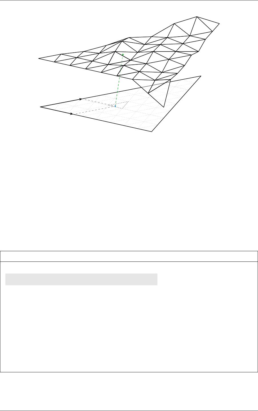
11.9 Vertex random access 11 Device-side functions
Fig. 11.1 - A displaced micro-mesh triangle hit returns the barycentrics in the space
of the base triangle.
In such a case, optixGetTriangleBarycentrics returns the barycentrics of the hit point in
the space of the base triangle, not the micro triangle as shown in Figure 11.1 (also see
Displaced micro-mesh triangle primitive section for the terminology of base and micro
triangles). This allows for easy interpolation of custom vertex attributes that are specified at
the vertices of the base triangle of a displaced micro-mesh triangle primitive. Function
optixGetMicroTriangleBarycentricsData can be used to query the barycentrics in base
triangle space of the three micro vertices of the intersected micro triangle. The helper function
optixBaseBarycentricsToMicroBarycentrics can be used to convert the barycentrics of
the current hit from base triangle space to the micro triangle space. This can be used to
interpolate the positions of the micro vertices to compute a hit position in object space.
Listing 11.9
float3 vertices[3];
optixGetMicroTriangleVertexData( vertices );
Returns the vertices of the
current DMM micro triangle hit
float2 hitBaseBarycentrics = optixGetTriangleBarycentrics();
float2 microVertexBaseBarycentrics[3];
optixGetMicroTriangleBarycentricsData( microVertexBaseBarycentrics );
float2 microBary = optixBaseBarycentricsToMicroBarycentrics(
hitBaseBarycentrics, microVertexBaseBarycentrics );
float3 hitP = (1 - microBary.x - microBary.y) * vertices[0]
+ microBary.x * vertices[1] + microBary.y * vertices[2];
© 2023 NVIDIA Corporation NVIDIA OptiX 7.7 ± Programming Guide 105

11 Device-side functions 11.11 Transform list
11.10 Geometry acceleration structure motion options
In addition to the motion vertex interpolation performed by optixGetTriangleVertexData,
interpolation may also be desired for other user-managed vertex data, such as interpolating
vertices in a custom motion intersection, or interpolating user-provided shading normals in
the closest-hit shader. NVIDIA OptiX provides the following functions to obtain the motion
options for a geometry acceleration structure:
optixGetGASMotionTimeBegin
optixGetGASMotionTimeEnd
optixGetGASMotionStepCount
For example, if the number of motion keys for the user vertex data equals the number of
motion keys in the geometry acceleration structure, the user can compute the left key index
and intra-key interpolation time as follows:
Listing 11.10
OptixTraversableHandle gas = optixGetGASTraversableHandle();
float currentTime = optixGetRayTime();
float timeBegin = optixGetGASMotionTimeBegin(gas);
float timeEnd = optixGetGASMotionTimeEnd(gas);
int numIntervals = optixGetGASMotionStepCount(gas) - 1;
float time =
(globalt - timeBegin) * numIntervals / (timeEnd - timeBegin);
time = max(0.f, min(numIntervals, time));
float fltKey = floorf(time);
float intraKeyTime = time - fltKey;
int leftKey = (int)fltKey;
11.11 Transform list
In a multi-level/IAS scene graph, one or more transformations are applied to each primitive.
NVIDIA OptiX provides intrinsics to read a transform list at the current primitive. The
transform list contains all transforms on the path through the scene graph from the root
traversable (passed to optixTrace) to the current primitive. Function
optixGetTransformListSize returns the number of entries in the transform list and
optixGetTransformListHandle returns the traversable handle of the transform entries.
Function optixGetTransformTypeFromHandle returns the type of a traversable handle and
can be of one of the following types:
OPTIX_TRANSFORM_TYPE_INSTANCE
An instance in an instance acceleration structure. Function
optixGetInstanceIdFromHandle returns the instance user ID. Functions
optixGetInstanceTransformFromHandle and
optixGetInstanceInverseTransformFromHandle return the instance transform and its
inverse. Function optixGetInstanceChildFromHandle returns the traversable handle
referenced by the instance via OptixInstance::traversableHandle.
106 NVIDIA OptiX 7.7 ± Programming Guide © 2023 NVIDIA Corporation

11.11 Transform list 11 Device-side functions
OPTIX_TRANSFORM_TYPE_STATIC_TRANSFORM
A transform corresponding to the OptixStaticTransform traversable. Function
optixGetStaticTransformFromHandle returns a pointer to the traversable.
OPTIX_TRANSFORM_TYPE_MATRIX_MOTION_TRANSFORM
A transform corresponding to the OptixMatrixMotionTransform traversable. Function
optixGetMatrixMotionTransformFromHandle returns a pointer to the traversable.
OPTIX_TRANSFORM_TYPE_SRT_MOTION_TRANSFORM
A transform corresponding to the OptixSRTMotionTransform traversable. Function
optixGetSRTMotionTransformFromHandle returns a pointer to the traversable.
Only use these pointers to read data associated with these nodes. Writing data to any
traversables that are active during a launch produces undefined results.
For example:
Listing 11.11 – Generic world to object transform computation
float4 mtrx[3];
for (unsigned int i = 0; i < optixGetTransformListSize(); ++i) {
OptixTraversableHandle handle = optixGetTransformListHandle(i);
float4 trf[3];
switch(optixGetTransformTypeFromHandle(handle)) {
case OPTIX_TRANSFORM_TYPE_INSTANCE: {
const float4* trns =
optixGetInstanceInverseTransformFromHandle(handle);
trf[0] = trns[0];
trf[1] = trns[1];
trf[2] = trns[2];
} break;
case OPTIX_TRANSFORM_TYPE_STATIC_TRANSFORM : {
const OptixStaticTransform* traversable =
optixGetStaticTransformFromHandle(handle);
...
Compute trf
} break;
case OPTIX_TRANSFORM_TYPE_MATRIX_MOTION_TRANSFORM : {
const OptixMatrixMotionTransform* traversable =
optixGetMatrixMotionTransformFromHandle(handle);
...
Compute trf
} break;
case OPTIX_TRANSFORM_TYPE_SRT_MOTION_TRANSFORM : {
const OptixSRTMotionTransform* traversable =
optixGetSRTMotionTransformFromHandle(handle);
...
Compute trf
} break;
default:
continue;
}
if (i == 0) {
mtrx[0] = trf[0];
© 2023 NVIDIA Corporation NVIDIA OptiX 7.7 ± Programming Guide 107

11 Device-side functions 11.12 Instance random access
mtrx[1] = trf[1];
mtrx[2] = trf[2];
} else {
float4 m0 = mtrx[0], m1 = mtrx[1], m2 = mtrx[2];
mtrx[0] = rowMatrixMul(m0, m1, m2, trf[0]);
mtrx[1] = rowMatrixMul(m0, m1, m2, trf[1]);
mtrx[2] = rowMatrixMul(m0, m1, m2, trf[2]);
Right multiply rows
with pre-multiplied
matrix
}
}
An application can implement a customized transformation evaluation function (for example,
to get the world-to-object transformation matrix) using these intrinsics. Doing so can be
beneficial as one can take advantage of the particular structure of the scene graph, for
example, when a scene graph features a known maximum of transforms and only a subset of
transform types are used. However, it is more important to properly specify the
OptixPipelineCompileOptions::traversableGraphFlags and
OptixPipelineCompileOptions::usesMotionBlur compile options based on which subset
of scene graphs need to be supported. These compile options allow for optimizations to the
intrinsics by compile-time removal of non-supported cases. For example, if only one level of
instancing is necessary and no motion blur transforms need to be supported, set
traversableGraphFlags to
OPTIX_TRAVERSABLE_GRAPH_FLAG_ALLOW_SINGLE_LEVEL_INSTANCING. If set, device
functions such as optixGetWorldToObjectTransformMatrix and
optixGetObjectToWorldTransformMatrix are equally performant as a custom
implementation.
Handles passed back from optixGetTransformListHandle can be stored or passed to other
functions in which they can be decoded. Functions
optixGetWorldToObjectTransformMatrix and optixGetObjectToWorldTransformMatrix
are only available in the context of an intersection (IS, AH, CH programs). As such, it may
also be required to use a customized transformation evaluation function, fetching the
transformations from previously stored handles.
11.12 Instance random access
Transform lists are the preferred way to access data of an NVIDIA OptiX instance associated
with the current intersection in intersection, any-hit and closest-hit programs. However, a
user may require random access to instance data of any other instance in the instance
acceleration structure, not associated with the current intersection. When an instance
acceleration structure is built with the OPTIX_BUILD_FLAG_ALLOW_RANDOM_INSTANCE_ACCESS
flag set, the application can query the instance traversable handle of any instance in the
instance acceleration structure. Because the instance acceleration structure contains the
instance data, the application can safely release its own instance data buffers on the device,
thereby lowering overall memory usage.
The function optixGetInstanceTraversableFromIAS returns the traversable handle of an
instance in the instance acceleration structure.
108 NVIDIA OptiX 7.7 ± Programming Guide © 2023 NVIDIA Corporation

11.13 Terminating or ignoring traversal 11 Device-side functions
Listing 11.12
OptixTraversableHandle optixGetInstanceTraversableFromIAS(
OptixTraversableHandle ias,
unsigned int instIdx);
The user can call functions optixGetInstanceIdFromHandle,
optixGetInstanceChildFromHandle, optixGetInstanceTransformFromHandle and
optixGetInstanceInverseTransformFromHandle to obtain the user instance id, child
traversable handle, object-to-world transform and world-to-object transform from the
instance traversable handle.
For example:
Listing 11.13
OptixTraversableHandle instanceHandle =
optixGetInstanceTraversableFromIAS( iasHandle, instanceIdx );
const float4* transform =
optixGetInstanceTransformFromHandle( instanceHandle );
This functions’ behavior is undefined when the traversable handle doesn’t reference a valid
instance acceleration structure traversable, the instance acceleration structure wasn’t built
with the OPTIX_BUILD_FLAG_ALLOW_RANDOM_INSTANCE_ACCESS flag set or the instance index
is not within the valid range.
11.13 Terminating or ignoring traversal
In any-hit programs, use the following functions to control traversal:
optixTerminateRay
Causes the traversal execution associated with the current ray to immediately terminate.
After termination, the closest-hit program associated with the ray is called.
optixIgnoreIntersection
Causes the current potential intersection to be discarded. This intersection will not
become the new closest hit intersection associated with the ray.
These functions do not return to the caller and they immediately terminate the program. Any
modifications to ray payload values must be set before calling these functions.
11.14 Exceptions
Exceptions allow NVIDIA OptiX to check for invariants and to report details about violations.
To enable exception checks, set the OptixPipelineCompileOptions::exceptionFlags field
with a bitwise combination of OptixExceptionFlags. Depending on the scenario and
combination of flags, enabling exceptions can lead to severe overhead, so some flags should
be mainly used in internal and debug builds.
There are several different kinds of exceptions, which are enabled based on the set of flags
specified:
© 2023 NVIDIA Corporation NVIDIA OptiX 7.7 ± Programming Guide 109

11 Device-side functions 11.14 Exceptions
OPTIX_EXCEPTION_FLAG_NONE
No exception set (default).
OPTIX_EXCEPTION_FLAG_STACK_OVERFLOW
Checks for overflow in the continuation stack specified with the
continuationStackSize parameter to optixPipelineSetStackSize. When this
exception is enabled, the overhead is usually negligible.
OPTIX_EXCEPTION_FLAG_TRACE_DEPTH
Before tracing a new ray, checks to see if the ray depth exceeds the value specified with
OptixPipelineLinkOptions::maxTraceDepth. Some stack overflows are only detected
if the exception for trace depth is enabled as well (or the value of
OptixPipelineLinkOptions::maxTraceDepth is correct). When this exception is
enabled, the overhead is usually negligible.
OPTIX_EXCEPTION_FLAG_USER
Enables the use of optixThrowException().
OPTIX_EXCEPTION_FLAG_DEBUG
Enables a number of run time checks including overflows for the traversable list, the
validation of the set of traversables encountered at runtime, the validation of traced rays
for nan or inf values, the validation of parameter counts for callable programs, and the
validation of the SBT index when calling callable programs. When enabled, the overhead
of this exception ranges from negligible to severe, depending on the type of GPU and the
set of RTX features that are active.
If an exception occurs, the exception program is invoked. The exception program can be
specified with an SBT record set in OptixShaderBindingTable::exceptionRecord. If
exception flags are specified but no exception program is provided, a default exception
program is provided by NVIDIA OptiX. This built-in exception program prints the first five
exceptions that occurred to stdout to limit the amount of exception printing. Control does
not return to the location that triggered the exception, and execution of the launch index ends.
In exception programs, the kind of exception that occurred can be queried with
optixGetExceptionCode.
A number of exception codes are defined for the built-in exceptions.
Some exceptions provide additional information, accessed by API functions.
OPTIX_EXCEPTION_CODE_STACK_OVERFLOW
Stack overflow of the continuation stack. No information functions.
OPTIX_EXCEPTION_CODE_TRACE_DEPTH_EXCEEDED
The trace depth was exceeded. No information functions.
OPTIX_EXCEPTION_CODE_TRAVERSAL_DEPTH_EXCEEDED
The traversal depth was exceeded. Information functions:
optixGetTransformListSize()
optixGetTransformListHandle()
OPTIX_EXCEPTION_CODE_TRAVERSAL_INVALID_TRAVERSABLE
Traversal encountered an invalid traversable type. Information functions:
110 NVIDIA OptiX 7.7 ± Programming Guide © 2023 NVIDIA Corporation

11.14 Exceptions 11 Device-side functions
optixGetTransformListSize()
optixGetTransformListHandle()
optixGetExceptionInvalidTraversable()
OPTIX_EXCEPTION_CODE_TRAVERSAL_INVALID_MISS_SBT
The miss SBT record index is out of bounds. Information function:
optixGetExceptionInvalidSbtOffset()
OPTIX_EXCEPTION_CODE_TRAVERSAL_INVALID_HIT_SBT
The traversal hit SBT record index was out of bounds. Information functions:
optixGetTransformListSize()
optixGetTransformListHandle()
optixGetExceptionInvalidSbtOffset()
optixGetSbtGASIndex()
OPTIX_EXCEPTION_CODE_INVALID_RAY
The shader encountered a call to optixTrace with at least one of the float arguments
being inf or nan, or the tmin argument is negative. Information function:
optixGetExceptionInvalidRay()
OPTIX_EXCEPTION_CODE_CALLABLE_PARAMETER_MISMATCH
The shader encountered a call to either optixDirectCall or optixContinuationCall
where there is a mismatch of the provided arguments and the parameters of the callable
program which is called. Information function:
optixGetExceptionParameterMismatch()
OPTIX_EXCEPTION_CODE_CALLABLE_INVALID_SBT
The callable program SBT record index was out of bounds. Information functions:
optixGetExceptionInvalidSbtOffset()
OPTIX_EXCEPTION_CODE_CALLABLE_NO_DC_SBT_RECORD
The callable program SBT record does not contain a direct callable program. Information
functions:
optixGetExceptionInvalidSbtOffset()
OPTIX_EXCEPTION_CODE_CALLABLE_NO_CC_SBT_RECORD
The callable program SBT record does not contain a continuation callable program.
Information functions:
optixGetExceptionInvalidSbtOffset()
OPTIX_EXCEPTION_CODE_UNSUPPORTED_SINGLE_LEVEL_GAS
The traversable handle passed to optixTrace references a geometry acceleration
structure, but the associated pipeline doesn’t support single level geometry acceleration
structure traversal (See OptixPipelineCompileOptions::traversableGraphFlags).
Information functions:
optixGetTransformListSize()
optixGetTransformListHandle()
optixGetExceptionInvalidTraversable()
© 2023 NVIDIA Corporation NVIDIA OptiX 7.7 ± Programming Guide 111

11 Device-side functions 11.14 Exceptions
The following exception codes can be triggered by optixGetTriangleVertexData and
optixGetInstanceTraversableFromIAS when exceptions are enabled.
OPTIX_EXCEPTION_CODE_INVALID_VALUE_ARGUMENT_0
Two conditions can trigger this exception code:
•
The value for argument ias in a call to optixGetInstanceTraversableFromIAS is
not a valid instance acceleration structure.
•
The value for argument gas in a call to optixGetTriangleVertexData is not a valid
geometry acceleration structure.
OPTIX_EXCEPTION_CODE_INVALID_VALUE_ARGUMENT_1
The index passed is out of range.
OPTIX_EXCEPTION_CODE_INVALID_VALUE_ARGUMENT_2
The sbtGASIndex passed to optixGetTriangleVertexData is out of range.
OPTIX_EXCEPTION_CODE_UNSUPPORTED_DATA_ACCESS
Three conditions can trigger this exception code:
•
Function optixGetTriangleVertexData was called on an acceleration structure
that was built without OPTIX_BUILD_FLAG_ALLOW_RANDOM_VERTEX_ACCESS set.
•
Function optixGetInstanceTraversableFromIAS was called on an acceleration
structure built without OPTIX_BUILD_FLAG_ALLOW_RANDOM_INSTANCE_ACCESS set.
•
An acceleration structure built with motion was used in a pipeline without motion
enabled.
User exceptions can be thrown with values between 0 and 2
30
− 1. Zero to eight 32-bit-value
details can also be used to pass information to the exception program using a set of functions
of one to nine arguments, as shown in Listing 11.14.
Listing 11.14 – Function signatures for user exceptions
optixThrowException(
unsigned int code);
optixThrowException(
unsigned int code,
unsigned int detail0);
optixThrowException(
unsigned int code,
unsigned int detail0,
unsigned int detail1);
...
Exceptions for three to seven detail arguments
optixThrowException(
unsigned int code,
unsigned int detail0,
unsigned int detail1,
112 NVIDIA OptiX 7.7 ± Programming Guide © 2023 NVIDIA Corporation

11.14 Exceptions 11 Device-side functions
unsigned int detail2,
unsigned int detail3,
unsigned int detail4,
unsigned int detail5,
unsigned int detail6,
unsigned int detail7);
The details can be queried in the exception program with eight functions,
optixGetExceptionDetail_0() to optixGetExceptionDetail_7().
These functions’ behavior is undefined when exception detail for another exception code is
queried or if user exception detail that is queried was not set with optixThrowException.
© 2023 NVIDIA Corporation NVIDIA OptiX 7.7 ± Programming Guide 113

11 Device-side functions 11.14 Exceptions
114 NVIDIA OptiX 7.7 ± Programming Guide © 2023 NVIDIA Corporation

12 Payload
The ray payload is used to pass data between optixTrace and the programs invoked during
ray traversal. Payload values are passed to and returned from optixTrace, and follow a
copy-in/copy-out semantic. The payload is passed to all the intersection, any-hit, closest-hit
and miss programs that are invoked during the execution of optixTrace. The payload can be
read and written by each program using the thirty-two pairs of optixGetPayload and
optixSetPayload functions (for example, optixGetPayload_0 and optixSetPayload_0).
Setting a payload value using optixSetPayload causes the updated value to be visible in any
subsequent optixGetPayload calls until the return to the caller of optixTrace. Payload
values that are not explicitly set in a program remain unmodified. Payload values can be set
anywhere in a program. Payloads are limited in size and are encoded in a maximum of
thirty-two 32-bit integer values, which are held in registers where possible. To hold additional
state, these values may also encode pointers to stack-based variables or application-managed
global memory.
The number of available payload values can be configured globally for the entire pipeline
using the numPayloadValues field of OptixPipelineCompileOptions. When configured
globally per pipeline, all intersection, any-hit, closest-hit and miss programs agree on the
number of values in the payload and have read and write access to all payload values. The
lifetime of all payload values therefore extends over the entire optixTrace call. Configuring
a larger payload will thus generally increase register consumption.
Alternatively, the user can specify more fine-grained payload type semantics per program.
Each payload type is defined as some number of 32-bit integer values, with specific
read/write semantics for each value. These semantics declare which programs may read
and/or write to a particular payload value. OptiX can use these semantics to limit the lifetime
of payload values and possibly improve register consumption. Each optixTrace call is
associated with a single payload type. Similarly, each intersection, any-hit, closest-hit and
miss program is associated with one or more payload types. Up to eight payload types can be
specified per module using the OptixModuleCompileOptions as follows:
Listing 12.1
unsigned int semantics[2] = {
OPTIX_PAYLOAD_SEMANTICS_TRACE_CALLER_WRITE
| OPTIX_PAYLOAD_SEMANTICS_CH_READ,
OPTIX_PAYLOAD_SEMANTICS_TRACE_CALLER_READ
| OPTIX_PAYLOAD_SEMANTICS_CH_WRITE,
};
OptixPayloadType payloadType;
payloadType.numPayloadValues = 2;
payloadType.payloadSemantics = semantics;
© 2023 NVIDIA Corporation NVIDIA OptiX 7.7 ± Programming Guide 115

12 Payload
OptixModuleCompileOptions moduleCompileOptions = {};
...
Option assignment
moduleCompileOptions.numPayloadTypes = 1;
moduleCompileOptions.payloadTypes = &payloadType;
OptixPipelineCompileOptions pipelineCompileOptions = {};
...
Option assignment
pipelineCompileOptions.numPayloadValues = 0;
Note: Shader output payload values that are exclusively written in closest-hit and/or
miss shaders and read by the caller generally have the shortest lifetime
(OPTIX_PAYLOAD_SEMANTICS_TRACE_CALLER_READ |
OPTIX_PAYLOAD_SEMANTICS_CH_WRITE | OPTIX_PAYLOAD_SEMANTICS_MS_WRITE), thus
providing OptiX with the most optimization potential.
Setting the OptixPipelineCompileOptions::numPayloadValues to zero signals that the
modules in a pipeline use payload types. Modules compiled with different payload types
may be freely combined in a pipeline. While the maximum number of payload types per
module is eight, the pipeline itself can exceed this limit due to the ability to link modules with
disjoint payload types. Within a module the payload types are referenced by ID, where the ID
of a type equals its index in the payload type array payloadTypes specified in
OptixModuleCompileOptions. Each program in a module specifies one or more supported
payload types using the optixSetPayloadTypes function. When called, this function must
be invoked unconditionally at the top of the program. Omitting the call to
optixSetPayloadTypes or with OPTIX_PAYLOAD_TYPE_DEFAULT as argument indicates that
the program supports all payload types specified in OptixModuleCompileOptions. If the
OptixModuleCompileOptions specify multiple payload types each optixTrace call must
supply a single payload type. All programs invoked during the execution of an optixTrace
call must be associated with the payload type passed to that optixTrace. It is the
responsibility of the user to setup the Shader Binding Table so the payload type of any
programs invoked in a trace execution match the type associated with the optixTrace call.
See
“Shader binding table” (page 77). Type mismatches result in undefined behavior. When
debug exceptions are enabled, OptiX will raise an
OPTIX_EXCEPTION_CODE_PAYLOAD_TYPE_MISMATCH exception when program payload type
mismatches are detected. The payload types argument passed to optixTrace and
optixSetPayloadTypes must be a compile time constant. Note that a user may assign
matching payload types to different IDs in different modules. Payload types are considered to
match if they agree on the number of payload values and the semantics of each value,
irrespective of their IDs within a module.
Listing 12.2
extern "C" __global__ void __anyhit__ah()
{
optixSetPayloadTypes(
OPTIX_PAYLOAD_TYPE_ID_1 |
OPTIX_PAYLOAD_TYPE_ID_3);
Support only types 1 and 3 specied in
OptixModuleCompileOptions:
}
116 NVIDIA OptiX 7.7 ± Programming Guide © 2023 NVIDIA Corporation

12 Payload
extern "C" __global__ void __intersection__default()
{
optixSetPayloadTypes(
OPTIX_PAYLOAD_TYPE_DEFAULT);
Support all types specied in
OptixModuleCompileOptions:
}
extern "C" __global__ void __raygen__rg()
{
unsigned int p0, p1;
optixTrace(
OPTIX_PAYLOAD_TYPE_ID_0, ..., p0, p1);
All IS, AH, CH and MS programs
associated with this call need to
be associated with payload type
0.
}
Note that reading or writing a payload value inside a program without the appropriate read
or write semantics for that value will result in a compilation failure. Programs associated with
multiple types will be compiled once for each type. Programs in a program group are
associated with a single specific type only. The user configures the target type with
OptixProgramGroupOptions::payloadType. If there is only one unique payload type that is
supported by all programs specified in the group description OptiX will deduce the unique
type and OptixProgramGroupOptions::payloadType may be left zero.
Listing 12.3
OptixProgramGroupDesc desc = {};
desc.kind = OPTIX_PROGRAM_GROUP_KIND_HITGROUP;
desc.hitgroup.moduleCH = moduleA;
desc.hitgroup.entryFunctionNameCH = "__closesthit__ch"
desc.hitgroup.moduleAH = moduleB;
desc.hitgroup.entryFunctionNameAH = "__anyhit__ah"
OptixProgramGroupOptions options = {};
options.payloadType = &payloadTypes[1];
The payloadType can be dened
explicitly...
options.payloadType = nullptr;
...or let OptiX try to nd a unique type match:
optixProgramGroupCreate(
..., &desc, 1, options, ..., &programGroup);
© 2023 NVIDIA Corporation NVIDIA OptiX 7.7 ± Programming Guide 117

12 Payload
118 NVIDIA OptiX 7.7 ± Programming Guide © 2023 NVIDIA Corporation

13 Callables
13.1 Callable programs
Callable programs allow for additional programmability within the standard set of NVIDIA
OptiX 7 programs. They are invoked using their index in the shader binding table. Invoking a
function with its index enables a function call to change its target at runtime without having
to recompile the program. This increase in flexibility can enable, for example, different
shading effects in response to user input or programs that can be customized based on the
scene setup.
Two types of callable programs exist in NVIDIA OptiX 7: direct callables and continuation
callables. Unlike direct callables, continuation callables can call the function optixTrace.
Direct callables are called immediately, but because of their additional capability,
continuation callables need to be executed by the scheduler. This may result in additional
overhead when running continuation callables.
Since continuation-callable programs can only be called from other continuation-callable
programs, nested callables that need to call optixTrace must be marked as continuation
callables. This has implications when creating a shader network from callables that trace rays.
In such cases, refactoring the shader network to avoid calling optixTrace is recommended to
improve overall performance.
The use of continuation callables can also lead to better overall performance, especially if the
code block in question is part of divergent code execution. A simple example is a variety of
material parameter inputs, such as different noise functions or a complex bitmap network.
Using a continuation callable for each of these inputs allows the scheduler to more efficiently
execute these complex snippets and to potentially resolve most of the divergent code
execution.
Direct callables can be called from any program type except exception. Continuation callables
can be called from ray-generation, closest-hit, and miss programs.
There are three parts to calling a callable program.
1. Implementation of the program you wish to call. That program needs to be annotated
with the appropriate name prefix __direct_callable__ or
__continuation_callable__.
2. The inclusion of a shader binding table record for the program group that contains the
callable program.
3. The call in a program of the callable using the functions optixDirectCall and
optixContinuationCall, shown in
Listing 13.1 (page 120).
© 2023 NVIDIA Corporation NVIDIA OptiX 7.7 ± Programming Guide 119

13 Callables 13.2 Non-inlined functions
Listing 13.1 – Device functions with variadic templates
template<typename ReturnT, typename... ArgTypes>
ReturnT optixDirectCall(
unsigned int sbtIndex, ArgTypes... args);
template<typename ReturnT, typename... ArgTypes>
ReturnT optixContinuationCall(
unsigned int sbtIndex, ArgTypes... args);
The device-code compilation of these variadic templates requires C++11 or later.
The sbtIndex argument is an index of the array of callable shader binding table entries
specified with the OptixShaderBindingTable::callablesRecordBase parameter to
optixTrace. The program group for a callable can contain both a direct-callable and
continuation-callable program, though these programs share a single record in the shader
binding table.
13.2 Non-inlined functions
While the shortest execution time is often achieved by aggressively inlining functions,
inlining can lengthen compilation time. OptiX supports the use of non-inlined functions that
can be referenced by name and participate in cross-module linking. However, non-inlined
functions cannot use OptiX device-side API functions without being automatically inlined
during module creation.
To disable this automatic inlining, define the function as OptiX enabled by adding the prefix
__optix_enabled__ to the function name. Since OptiX-enabled functions do not have entries
in the shader binding table, they do not have any associated data. They can be called from
other OptiX-enabled functions and any entry function except for within exception programs.
As with all functions, taking the address of the function is not permitted. If function pointer
semantics are required, direct callable functions should be used.
OptiX-enabled functions may incur some compile and runtime overhead similar to direct
callables. See the table in
“Device-side functions” (page 95) for a list of OptiX device-side API
functions that are callable from OptiX-enabled functions.
120 NVIDIA OptiX 7.7 ± Programming Guide © 2023 NVIDIA Corporation

14 NVIDIA AI Denoiser
Image areas that have not yet fully converged during rendering will often exhibit pixel-scale
noise due to the insufficient amount of information gathered by the renderer. This grainy
appearance in an image may be caused by low iteration counts, especially in scenes with
complex lighting environments and material calculations.
The NVIDIA AI Denoiser can estimate the converged image from a partially converged
image. Instead of improving image quality through a larger number of path tracing iterations,
the denoiser can produce images of acceptable quality with far fewer iterations by
post-processing the image.
The denoiser is based on statistical data sets that guide the denoising process. These data,
represented by a binary blob called a training model, are produced from a large number of
rendered images in different stages of convergence. The images are used as input to an
underlying deep learning system. (See the NVIDIA Developer article
“Deep Learning”
1
for
more information about deep-learning systems.)
Because deep-learning training needs significant computational resources — even obtaining a
sufficient number of partially converged images can be difficult — a general-purpose model
is included with the OptiX software. This model is suitable for many renderers. However, the
model may not yield optimal results when applied to images produced by renderers with
very different noise characteristics compared to those used in the original training data.
Post-processing rendered images includes image filters, such as blurring or sharpening, or
reconstruction filters, such as box, triangle, or Gaussian filters. Custom post-processing
performed on a noisy image can lead to unsatisfactory denoising results. During
post-processing, the original high-frequency, per-pixel noise may become smeared across
multiple pixels, making it more difficult to detect and be handled by the model. Therefore,
post-processing operations should be done after the denoising process, while reconstruction
filters should be implemented by using filter importance-sampling.
In general, the pixel color space of an image that is used as input for the denoiser should
match the color space of the images on which the denoiser was trained. However, slight
variations, such as substituting sRGB with a simple gamma curve, should not have a
noticeable impact. Images used for the training model included with the NVIDIA AI
Denoiser distribution were output directly as HDR data.
1. http://developer.nvidia.com/deep-learning
© 2023 NVIDIA Corporation NVIDIA OptiX 7.7 ± Programming Guide 121

14 NVIDIA AI Denoiser 14.1 Functions and data structures for denoising
14.1 Functions and data structures for denoising
Calling function optixDenoiserCreate creates a denoiser object:
Listing 14.1
OptixResult optixDenoiserCreate(
OptixDeviceContext context,
OptixDenoiserModelKind modelKind,
const OptixDenoiserOptions* options,
OptixDenoiser* denoiser);
The OptixDenoiserModelKind is one of the following enum values:
OPTIX_DENOISER_MODEL_KIND_LDR
The input image data contains values of limited dynamic range with RGB values in the
range 0.0 to 1.0.
OPTIX_DENOISER_MODEL_KIND_HDR
The input image data contains values of high dynamic range with RGB values in the
range of 0.0 to approximately 10,000.0 or more.
OPTIX_DENOISER_MODEL_KIND_AOV
Separate passes can be defined by many rendering systems using arbitrary output
variables, or AOVs. AOV images from a rendering system can contain diffuse, emission,
glossy, specular or other types of data. High dynamic range AOV images can be passed
as input layers to optixDenoiserInvoke in addition to the beauty, RGB, albedo and
normal images. The AOV mode can be used to denoise multiple layers simultaneously
and may reduce processing time.
After denoising, the denoised output layers can be composited to a noise-free beauty
layer, typically by adding all RGB values from the denoised layers.
The first OptixDenoiserLayer in the list of layers passed to optixDenoiserInvoke is
the noisy beauty image. Subsequent layers in this list are noisy AOVs. A noisy beauty
image is required in all modes of OptixDenoiserModelKind and the denoised image for
each given layer is written back in OptixDenoiserLayer::output.
OPTIX_DENOISER_MODEL_KIND_TEMPORAL
In this mode, a sequence of images is denoised to eliminate temporal noise. It requires
the denoised beauty image from the previous frame in
OptixDenoiserLayer::previousOutput. The flow vector image is specified by
OptixDenoiserGuideLayer::flow. OptixDenoiserParams::hdrIntensity must be set
in this mode.
In the first frame of a sequence, previousOutput could be set to the noisy beauty image
of the first frame instead of the denoised version and all flow vectors set to zero.
previousOutput is read in optixDenoiserInvoke before writing a new output, so
previousOutput could be set to output (the same buffer) for efficiency if useful in the
application.
122 NVIDIA OptiX 7.7 ± Programming Guide © 2023 NVIDIA Corporation

14.1 Functions and data structures for denoising 14 NVIDIA AI Denoiser
OPTIX_DENOISER_MODEL_KIND_TEMPORAL_AOV
In this mode, the following two additional fields are defined:
•
OptixDenoiserGuideLayer::previousOutputInternalGuideLayer
•
OptixDenoiserGuideLayer::outputInternalGuideLayer
The image type for both fields is a guide layer, an OptixImage2D of type
OPTIX_PIXEL_FORMAT_INTERNAL_GUIDE_LAYER. Temporal denoising relies on these
internal guide layers to carry information from the previous denoising pass, specified
with previousOutputInternalGuideLayer and outputInternalGuideLayer in the
OptixDenoiserGuideLayer struct. A set of guide layers must be provided to the
denoising pass as both input and output. These layers have the format
OPTIX_PIXEL_FORMAT_INTERNAL_GUIDE_LAYER and should be sized according to the
field internalGuideLayerPixelSizeInBytes returned by
optixDenoiserComputeMemoryResources.
An internal guide layer is a densely packed format, where each pixel has size
OptixDenoiserSizes::internalGuideLayerPixelSizeInBytes, and each row is
width × pixel size. The width and height of the guide layers are set to the same
dimensions that are used for the other layer images. The pixelStrideInBytes field of
the guide layer is set to internalGuideLayerPixelSizeInBytes. The
rowStrideInBytes field is set to width × internalGuideLayerPixelSizeInBytes.
The parameter OptixDenoiserParams::temporalModeUsePreviousLayers controls the
use of previous layers in denoising calculations. In temporal mode, setting this to 1
indicates the denoiser should read the values of the previous frame. Set to 0 for initial
frames or when you want to reset the temporal sequence. In the first frame, when using
temporal denoising modes, OptixDenoiserGuideLayer::flow must either contain valid
motion vectors if available, otherwise the xy vectors must be set to zero (no motion). In
temporal upscaling mode OptixDenoiserLayer::previousOutput is not accessed when
OptixDenoiserParams::temporalModeUsePreviousLayers is not set.
Each new sequence should contain the noisy beauty image as the value of
previousOutput. The previousOutputInternalGuideLayer image content must be set
to zero for the first frame.
Motion vectors must be set to zero if they are not available for the first frame.
Fields previousOutputInternalGuideLayer and outputInternalGuideLayer must
refer to two separate buffers; memory cannot be shared between these two buffers,
regardless of the tiling mode. The buffer memory locations must start at a 16-byte
aligned address or optixDenoiserInvoke will return an error code. After denoising a
frame, these two buffers must be exchanged, so that outputInternalGuideLayer
becomes prevousOutputInternalGuideLayer for the next frame. Instead of copying
data into the previous guide layer, you should use a double-buffering strategy by
swapping the content of the two OptixImage2D structs. You should also use double
buffering for the output and previousOutput fields of the OptixDenoiserLayer struct.
OPTIX_DENOISER_MODEL_KIND_UPSCALE2X
OPTIX_DENOISER_MODEL_KIND_TEMPORAL_UPSCALE2X
These modes upscale the input image by a factor of two in both dimensions. All output
images must be allocated accordingly using twice the original size of the input width and
height:
•
OptixDenoiserLayer::previousOutput
•
OptixDenoiserLayer::output
© 2023 NVIDIA Corporation NVIDIA OptiX 7.7 ± Programming Guide 123

14 NVIDIA AI Denoiser 14.1 Functions and data structures for denoising
•
OptixDenoiserGuideLayer::previousOutputInternalGuideLayer
•
OptixDenoiserGuideLayer::outputInternalGuideLayer
When using OPTIX_DENOISER_MODEL_KIND_TEMPORAL_UPSCALE2X mode for the first
frame, previousOutputInternalGuideLayer image content must be set to zero. The
previousOutput field is ignored in this mode and just the memory needs to be allocated.
Internally, the noisy beauty image will be upscaled by a factor of two and used as the
previous output (similar to the non-upcaling mode where the noisy beauty image should
be passed as the previously denoised output).
The denoiser options determine the type of guide layers used:
Listing 14.2
typedef struct OptixDenoiserOptions {
unsigned int guideAlbedo;
unsigned int guideNormal;
} OptixDenoiserOptions;
A denoiser object can also be created using a user-defined model:
Listing 14.3
OptixResult optixDenoiserCreateWithUserModel(
OptixDeviceContext context,
const void* userData,
size_t userDataSizeInBytes,
OptixDenoiser* denoiser);
After denoising, optixDenoiserDestroy should be called to destroy the denoiser object
along with associated host resources:
Listing 14.4
OptixResult optixDenoiserDestroy(
OptixDenoiser denoiser);
14.1.1 Structure and use of image buers
An RGB image buffer that contain a noisy image is provided as input to the denoising
process. The optional fourth (alpha) channel of the image can be configured so that it is
ignored by the denoiser. Note that this buffer must contain values between 0 and 1 for each of
the three color channels (for example, as the result of tone-mapping) and should be encoded
in sRGB or gamma space with a gamma value of 2.2 when working with low dynamic range
(LDR) input.
When working with high dynamic range (HDR) input instead, RGB values in the color buffer
should be in a range from zero to 10,000, and on average not too close to zero, to match the
built-in model. Images in HDR format can contain single, extremely bright, nonconverted
pixels, called fireflies. Using a preprocess pass that corrects drastic under- or over-exposure
along with clipping or filtering of fireflies on the HDR image can improve the denoising
124 NVIDIA OptiX 7.7 ± Programming Guide © 2023 NVIDIA Corporation
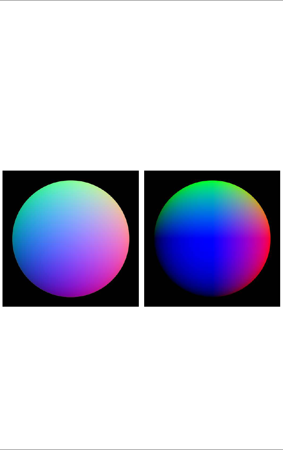
14.1 Functions and data structures for denoising 14 NVIDIA AI Denoiser
quality dramatically. Note, however, that no tone-mapping or gamma correction should be
performed on HDR data.
An optional, noise-free normal buffer contains the surface normal vectors of the primary hit
in camera space. The normal buffer is enabled by OptixDenoiserOptions::guideNormal
and specified by OptixDenoiserGuideLayer::normal. This buffer contains data in format
OPTIX_PIXEL_FORMAT_HALF3 or OPTIX_PIXEL_FORMAT_FLOAT3. These two formats can
represent the x, y and z components of a vector. The normal buffer must have the same type
and dimensions as the input buffer. The vectors in the normal buffer are normalized.
The camera space is assumed to be right-handed such that the camera is looking down the
negative z axis, and the up direction is along the y axis. The x axis points to the right.
Visualizing the normal vectors as colors for debugging purposes should produce images
similar to Figure 14.1 and Figure 14.2. The scanlines of the normal buffer proceed from top to
bottom in the images. The surface normal vector components have values in the range [-1.0,
1.0]. Figure 14.1 maps the component values to the range [0.0, 1.0]. Figure 14.2 clamps the
component values to [0.0,1.0]. The value of a normal buffer pixel for which there was no
primary hit is (0,0,0).
Fig. 14.1 - Surface normal vector components mapped
to [0.0, 1.0]
Fig. 14.2 - Surface normal vector components
clamped to [0.0, 1.0]
The normal buffer can improve denoising quality for scenes containing a high degree of
geometric detail. This detail may be part of the geometric complexity of the surface itself, or
may be the result of high-resolution images used in normal or bump mapping.
The optional, noise-free albedo image represents an approximation of the color of the surface
of the object, independent of view direction and lighting conditions. In physical terms, the
albedo is a single color value approximating the ratio of radiant exitance to the irradiance
under uniform lighting. The albedo value can be approximated for simple materials by using
the diffuse color of the first hit, or for layered materials, by using a weighted sum of the
albedo values of the individual BRDFs. For some objects such as perfect mirrors or highly
glossy materials, the quality of the denoising result might be improved by using the albedo
value of a subsequent hit instead. The fourth channel of this buffer is ignored, but must have
© 2023 NVIDIA Corporation NVIDIA OptiX 7.7 ± Programming Guide 125
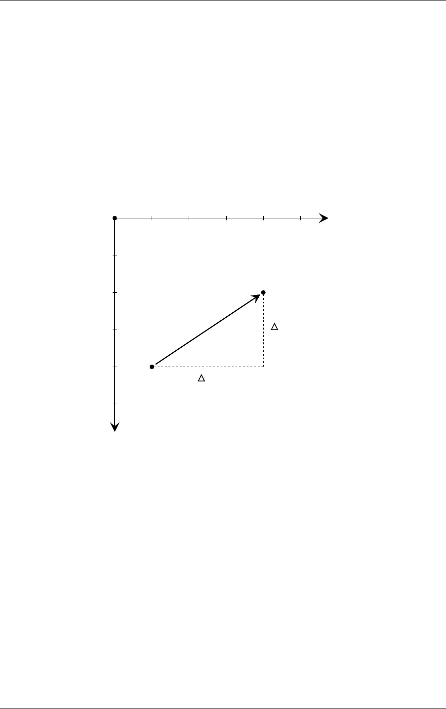
14 NVIDIA AI Denoiser 14.1 Functions and data structures for denoising
the same type and dimensions as the input buffer. Specifying albedo can dramatically
improve denoising quality, especially for very noisy input images.
14.1.2 Temporal denoising modes
In temporal denoising modes, pixels in the two-dimensional flow image represents the
motion from the previous to the current frame for that pixel. Pixels in the flow image can be
in one of two formats:
•
OPTIX_PIXEL_FORMAT_FLOAT2
•
OPTIX_PIXEL_FORMAT_HALF2
Figure 14.3 shows the definition of the flow vector based on the hit points of the current and
previous frames.
x
1 2 3 4 5
(1,4)
(4,2)
x = 3
y = – 2
flow vector
hit point
frame
previous
hit point
frame
current
y
1
2
3
4
5
(1,4)
(4,2)
x = 3
y = – 2
flow vector
hit point
frame
previous
hit point
frame
current
Fig. 14.3 - Definition of the flow vector based on the previous
and current hit points
If the hit point of the surface at position (4,2) in the current frame has moved from position
(1,4) in the previous frame, the flow vector at position (4,2) would be x=3, y=-2. This flow
vector definition assumes that images define y=0 at the top of the image. If images define y=0
at the bottom, this flow vector would be x=3, y=2. The flow vector coordinates must be
described with subpixel (fractional) precision.
The OptiX SDK provides the OptixDenoiser sample which could be used to verify properly
specified flow vectors. When invoked with -z, the tool looks up the position in the previous
frame of each pixel using the flow vector. The pixel value from the previous frame position is
looked up in the current frame position and written. When denoising a sequence with the -z
option, frame N with motion applied should look similar to frame N+1 in the noisy input
sequence. There should be no major jumps when comparing these images, just shading
differences as well as differences due to disocclusion and so forth.
126 NVIDIA OptiX 7.7 ± Programming Guide © 2023 NVIDIA Corporation

14.1 Functions and data structures for denoising 14 NVIDIA AI Denoiser
14.1.3 Allocating denoiser memory
To allocate the required, temporary device memory to run the denoiser, call function
optixDenoiserComputeMemoryResources:
Listing 14.5
OptixResult optixDenoiserComputeMemoryResources(
const OptixDenoiser denoiser,
unsigned int outputWidth,
unsigned int outputHeight,
OptixDenoiserSizes* returnSizes);
The memory requirements are returned in the fields of struct OptixDenoiserSizes:
Listing 14.6
typedef struct OptixDenoiserSizes {
size_t stateSizeInBytes;
size_t withOverlapScratchSizeInBytes;
size_t withoutOverlapScratchSizeInBytes;
unsigned int overlapWindowSizeInPixels;
size_t computeAverageColorSizeInBytes
size_t computeIntensitySizeInBytes
size_t internalGuideLayerPixelSizeInBytes;
} OptixDenoiserSizes;
The OptixDenoiserSizes values are used as input to function optixDenoiserSetup:
Listing 14.7
OptixResult optixDenoiserSetup(
OptixDenoiser denoiser,
CUstream stream,
unsigned int inputWidth,
unsigned int inputHeight,
CUdeviceptr denoiserState,
size_t denoiserStateSizeInBytes,
CUdeviceptr scratch,
size_t scratchSizeInBytes);
In tiling mode, the inputWidth and inputHeight values should include two times the
overlap size in the tile window dimensions.
© 2023 NVIDIA Corporation NVIDIA OptiX 7.7 ± Programming Guide 127

14 NVIDIA AI Denoiser 14.1 Functions and data structures for denoising
14.1.4 Using the denoiser
To execute denoising on a given image, call function optixDenoiserInvoke:
Listing 14.8
OptixResult optixDenoiserInvoke(
OptixDenoiser denoiser,
CUstream stream,
const OptixDenoiserParams* params,
CUdeviceptr denoiserState,
size_t denoiserStateSizeInBytes,
const OptixDenoiserGuideLayer* guideLayer,
const OptixDenoiserLayer* layers,
unsigned int numLayers,
unsigned int inputOffsetX,
unsigned int inputOffsetY,
CUdeviceptr scratch,
size_t scratchSizeInBytes);
When guide layers are enabled in OptixDenoiserOptions, the corresponding image buffers
are specified by the OptixDenoiserGuideLayer struct. In temporal modes a flow vector
image is specified by the OptixDenoiserGuideLayer::flow field.
Listing 14.9
typedef struct OptixDenoiserGuideLayer {
OptixImage2D albedo;
OptixImage2D normal;
OptixImage2D flow;
OptixImage2D previousOutputInternalGuideLayer;
OptixImage2D outputInternalGuideLayer;
} OptixDenoiserGuideLayer;
Beauty and AOV layers are specified by the OptixDenoiserLayer::input. The denoised
output of the beauty image in the layer is written to output. In temporal modes the denoised
beauty image from the previous frame for a layer is specified by
OptixDenoiserLayer::previousOutput.
Listing 14.10
typedef struct OptixDenoiserLayer {
OptixImage2D input
OptixImage2D previousOutput
OptixImage2D output
} OptixDenoiserLayer;
128 NVIDIA OptiX 7.7 ± Programming Guide © 2023 NVIDIA Corporation

14.1 Functions and data structures for denoising 14 NVIDIA AI Denoiser
The denoiser layers are defined by sets of struct OptixImage2D:
Listing 14.11
typedef struct OptixImage2D {
CUdeviceptr data
unsigned int width
unsigned int height
unsigned int rowStrideInBytes
unsigned int pixelStrideInBytes
OptixPixelFormat format
} OptixImage2D;
Function optixDenoiserInvoke executes the denoiser on a set of input data and produces
one output image. State memory must be available during the execution of the denoiser or
until optixDenoiserSetup is called with a new state memory pointer. Scratch memory
passed as a CUdeviceptr must be exclusively available to the denoiser during execution. It is
only used for the duration of optixDenoiserInvoke. Scratch and state memory sizes must
have a size greater than or equal to the sizes returned by
optixDenoiserComputeMemoryResources.
Input and output to the denoiser uses struct OptixImage2D to represent pixel data:
Listing 14.12
typedef struct OptixImage2D {
CUdeviceptr data
unsigned int width;
unsigned int height;
unsigned int rowStrideInBytes;
unsigned int pixelStrideInBytes;
OptixPixelFormat format;
} OptixImage2D;
Parameters inputOffsetX and inputOffsetY are pixel offsets in the inputLayers image.
These offsets specify the beginning of the image without overlap. When denoising an entire
image without tiling, there is no overlap and inputOffsetX and inputOffsetY must be zero.
When denoising a tile which is adjacent to one of the four sides of the entire image the
corresponding offsets must also be zero; there is no overlap at the side adjacent to the image
border. Parameters inputWidth and inputHeight correspond to the values passed to
optixDenoiserComputeMemoryResources.
The structure of pixel data is defined by the enum OptixPixelFormat:
© 2023 NVIDIA Corporation NVIDIA OptiX 7.7 ± Programming Guide 129

14 NVIDIA AI Denoiser 14.1 Functions and data structures for denoising
Field name Description
OPTIX_PIXEL_FORMAT_HALF2 Two halfs, XY
OPTIX_PIXEL_FORMAT_HALF3 Three halfs, RGB/XYZ
OPTIX_PIXEL_FORMAT_HALF4 Four halfs, RGBA/XYZW
OPTIX_PIXEL_FORMAT_FLOAT2 Two floats, XY
OPTIX_PIXEL_FORMAT_FLOAT3 Three floats, RGB/XYZ
OPTIX_PIXEL_FORMAT_FLOAT4 Four floats, RGBA/XYZW
OPTIX_PIXEL_FORMAT_INTERNAL_GUIDE_LAYER internal format
The OptixPixelFormat value of the inputLayers must match the format that was specified
during optixDenoiserCreate. The outputLayer must have the same width, height and
pixel format as the input RGB(A) layer. All input layers must have the same width and height.
Further control over denoising is provided by the OptixDenoiserParams struct:
Listing 14.13
typedef struct OptixDenoiserParams {
OptixDenoiserAlphaMode denoiseAlpha;
CUdeviceptr hdrIntensity;
float blendFactor;
CUdeviceptr hdrAverageColor;
unsigned int temporalModeUsePreviousLayers;
} OptixDenoiserParams;
The denoiseAlpha field of OptixDenoiserParams defines how the optional alpha channel of
the noisy beauty image should be treated. The possible values of the
OptixDenoiserAlphaMode enum are:
OPTIX_DENOISER_ALPHA_MODE_COPY
This is the default, alpha is copied from input to output and not denoised.
OPTIX_DENOISER_ALPHA_MODE_ALPHA_AS_AOV
This will apply the denoiser weights to the alpha channel, treating it similarly to other
AOV channels. This is the most efficient method to get a denoised alpha channel.
OPTIX_DENOISER_ALPHA_MODE_FULL_DENOISE_PASS
A new denoising mode that is useful where the alpha channel has a substantially
different noise profile than the RGB image. If artifacts appear, such as extra halo areas
around alpha, this mode may yield better denoised alpha channels. However, this will
execute a separate inference pass on alpha, meaning that denoise execution will take
twice as long.
The blendFactor field specifies an interpolation weight between the noisy input image (1.0)
and the denoised output image (0.0). Calculation of hdrIntensity is described in
“Calculating the HDR intensity parameter” (page 131).
Parameter hdrAverageColor is used when the OPTIX_DENOISER_MODEL_KIND_AOV model
kind is set. This parameter is a pointer to three floats that are the average log color of the RGB
channels of the input image. The default value (the null pointer) will produce results that are
not optimal.
130 NVIDIA OptiX 7.7 ± Programming Guide © 2023 NVIDIA Corporation

14.1 Functions and data structures for denoising 14 NVIDIA AI Denoiser
When denoising entire images without tiling, the same scratch memory as passed to
optixDenoiserInvoke could be used.
14.1.5 Calculating the HDR average color of the AOV model
The function optixDenoiserComputeAverageColor computes the average logarithmic value
for each of the first three channels of the input image. When denoising tiles the intensity of
the entire image should be computed — not per tile — for consistent results.
The inputImage parameter must contain three or four components of type half or float. The
data type unsigned char is not supported.
The required scratch memory sizes for the API functions
optixDenoiserComputeAverageColor and optixDenoiserComputeIntensity should be
queried with optixDenoiserComputeMemoryResources. The scratch memory size for these
functions is stored in OptixDenoiserSizes::computeAverageColorSizeInBytes and
OptixDenoiserSizes::computeIntensitySizeInBytes
Listing 14.14
OptixResult optixDenoiserComputeAverageColor(
OptixDenoiser denoiser,
CUstream stream,
const OptixImage2D* inputImage,
CUdeviceptr outputAverageColor,
CUdeviceptr scratch,
size_t scratchSizeInBytes);
14.1.6 Calculating the HDR intensity parameter
The value of hdrIntensity in OptixDenoiserParams can be calculated in one of two ways.
A custom application-side, preprocessing pass on the image data could provide a result value
of type float.
Intensity can also be calculated by calling function optixDenoiserComputeIntensity:
Listing 14.15
OptixResult optixDenoiserComputeIntensity(
OptixDenoiser denoiser,
CUstream stream,
const OptixImage2D* inputImage,
CUdeviceptr outputIntensity,
CUdeviceptr scratch,
size_t scratchSizeInBytes);
Function optixDenoiserComputeIntensity calculates the logarithmic average intensity of
parameter inputImage. The calculated value is returned in parameter outputIntensity as a
pointer to a single value of type float.
Intensity calculation can be dependent on optixDenoiserInvoke. The params parameter of
optixDenoiserInvoke is a struct of type OptixDenoiserParams. By default, the
hdrIntensity field of OptixDenoiserParams is a null pointer. If hdrIntensity is not a null
© 2023 NVIDIA Corporation NVIDIA OptiX 7.7 ± Programming Guide 131

14 NVIDIA AI Denoiser 14.2 Using image tiles with the denoiser
pointer, it points to an array of RGB values that are multiplied by the output values in
outputIntensity. This is useful for denoising HDR images which are very dark or bright.
When denoising with tiles, the intensity of the entire image should first be computed for
consistent results across tiles. (Tiling is described in the “Using image tiles with the denoiser”
(page 132).)
For each RGB pixel in the inputImage the intensity is calculated and summed if it is greater
than 1e-8f as follows:
intensity = log(r × 0.212586 + g × 0.715170 + b × 0.072200)
The function returns:
0.18
exp
sum_o f _intensities
number_o f _summed_pixels
Execution of optixDenoiserComputeIntensity requires a scratch memory size in bytes of at
least:
sizeof(int) * (2 + inputImage::width * inputImage::height)
When denoising entire images (without tiling) the same scratch memory that is passed to
optixDenoiserInvoke can be used.
Further information about this tone-mapping strategy can be found in
“Photographic Tone
Reproduction for Digital Images”
2
by Erik Reinhard, et al.
14.2 Using image tiles with the denoiser
Denoising can be performed incrementally on subregions of an image to limit memory usage
during the denoising process. An image is divided in to a set of tiles defined by their width
and height, as well as a surrounding region of overlapping pixels to avoid discontinuities at
tile boundaries.
For example,
Figure 14.4 (page 133) describes a possible structure for tiles and their
overlapping regions using OptixImage2D:
2. http://www.cmap.polytechnique.fr/˜peyre/cours/x2005signal/hdr_photographic.pdf
132 NVIDIA OptiX 7.7 ± Programming Guide © 2023 NVIDIA Corporation
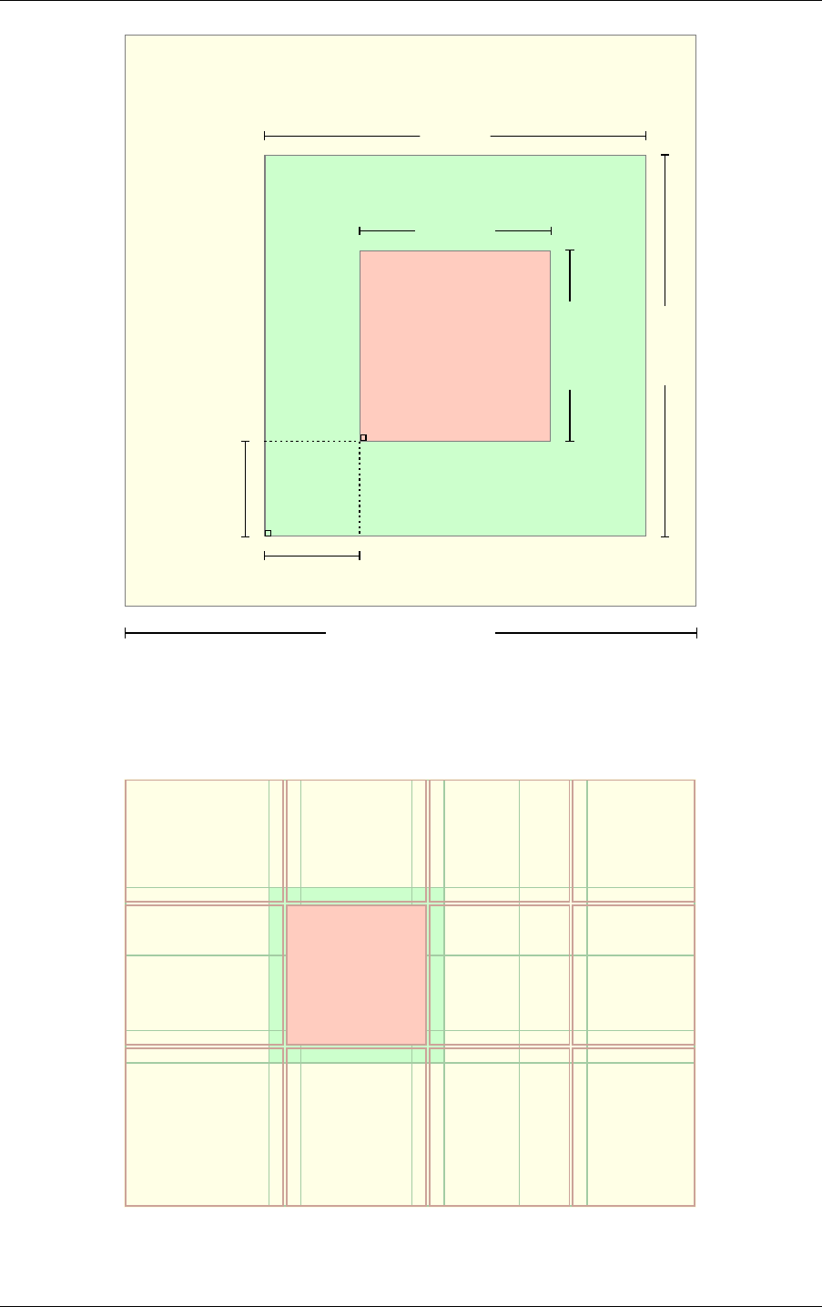
14.2 Using image tiles with the denoiser 14 NVIDIA AI Denoiser
void* outputBuffer;
void* inputBuffer;
OptixImage2D in;
OptixImage2D out;
out.heightout.height
out.widthout.width
in.heightin.height
in.widthin.width
out.rowStrideInBytes
in.rowStrideInBytes
out.rowStrideInBytes
in.rowStrideInBytes
unsigned int inputOffsetY;
unsigned int inputOffsetX;
in.data[0]
out.data[0]
Fig. 14.4 - An example of a denoiser tiling layout
The tiling code must accommodate tile sizes that do not evenly divide the image buffers.
Figure 14.5 shows a tile that with a consistent overlap size on all edges:
Fig. 14.5 - Output tile with overlap
© 2023 NVIDIA Corporation NVIDIA OptiX 7.7 ± Programming Guide 133
14 NVIDIA AI Denoiser 14.2 Using image tiles with the denoiser
Figure 14.6 (page 134) shows how a tiling procedure could vary the tile sizes based on their
position in the input and output buffers.
Fig. 14.6 - Tiles in corners showing variable overlap
The OptiX SDK includes an example of the tiling process. See header file
optix_denoiser_tiling.h in the SDK examples.
134 NVIDIA OptiX 7.7 ± Programming Guide © 2023 NVIDIA Corporation
