
San Jose State University San Jose State University
SJSU ScholarWorks SJSU ScholarWorks
Master's Projects Master's Theses and Graduate Research
Spring 2011
Decompiler For Pseudo Code Generation Decompiler For Pseudo Code Generation
Ankit Patel
San Jose State University
Follow this and additional works at: https://scholarworks.sjsu.edu/etd_projects
Part of the Other Computer Sciences Commons, Programming Languages and Compilers Commons,
and the Theory and Algorithms Commons
Recommended Citation Recommended Citation
Patel, Ankit, "Decompiler For Pseudo Code Generation" (2011).
Master's Projects
. 182.
DOI: https://doi.org/10.31979/etd.j55q-fr8s
https://scholarworks.sjsu.edu/etd_projects/182
This Master's Project is brought to you for free and open access by the Master's Theses and Graduate Research at
SJSU ScholarWorks. It has been accepted for inclusion in Master's Projects by an authorized administrator of SJSU
ScholarWorks. For more information, please contact [email protected].
i
Decompiler For Pseudo Code Generation
A Project Report
Presented to
The Faculty of the Department of Computer Science
San Jose State University
In Partial Fulfillment
Of the Requirements for the Degree
Master of Computer Science
By
Ankit Patel
May 2011
ii
© 2011
Ankit Patel
ALL RIGHTS RESERVED
SAN JOSÉ STATE UNIVERSITY
iii
The Undersigned Project Committee Approves the Project Titled
Decompiler For Pseudo Code Generation
By
Ankit Patel
APPROVED FOR THE DEPARTMENT OF COMPUTER SCIENCE
___________________________________________________________
Dr. Mark Stamp, Department of Computer Science Date
___________________________________________________________
Dr. Robert Chun, Department of Computer Science Date
___________________________________________________________
Ravi Savaliya, Senior Software Developer, Ebay Date
______________________________________________________________
Associate Dean Office of Graduate Studies and Research Date
iv
Abstract
Decompiler For Pseudo Code Generation
By Ankit Patel
Decompiling is an area of interest for researchers in the field of software reverse
engineering. When the source code from a high-level programming language is compiled, it
loses a great deal of information, including code structure, syntax, and punctuation.
The purpose of this research is to develop an algorithm that can efficiently decompile
assembly language into pseudo C code. There are tools available that claim to extract high-level
code from an executable file, but the results of these tools tend to be inaccurate and unreadable.
Our proposed algorithm can decompile assembly code to recover many basic high-level
programming structures, including if/else, loops, switches, and math instructions. The approach
adopted here is different from that of existing tools. Our algorithm performs three passes through
the assembly code, and includes a virtual execution of each assembly instruction. We also
construct a dependency graph and incidence list to aid in the decompilation.
v
ACKNOWLEDGEMENTS
I would like to thank Dr. Mark Stamp, for guiding me through this research project and
working with me to achieve this. I also thank him for his suggestions and contributions for
handling some of the difficulties faced during the course of this project. Without him, this would
not have been possible.
I would also like to thank Prof. Debra Caires for teaching me an efficient and effective
thesis documentation process.
vi
Table of Contents
1. Introduction ............................................................................................................................................... 1
1.1 Objective ............................................................................................................................................. 2
2. Background ............................................................................................................................................... 3
2.1 Fundamentals of forward and reverse engineering ............................................................................. 3
2.2 Windows portable executable file format ........................................................................................... 5
2.3 Assembly language ............................................................................................................................. 6
3. Decompilation ........................................................................................................................................... 9
3.1 Benefits of Decompiling ..................................................................................................................... 9
3.2 Decompiler problems ........................................................................................................................ 11
3.2.1 Information loss ......................................................................................................................... 11
3.2.2 Separation of .code and .data sections....................................................................................... 13
3.2.3 Differentiating original pointers from address offsets ............................................................... 14
3.2.4 Detecting constants from the pointers........................................................................................ 14
3.3 Limitations ........................................................................................................................................ 15
3.4 Types of Decompilers ....................................................................................................................... 15
3.5 Present decompiler tools ................................................................................................................... 17
5. Decompiler algorithm ............................................................................................................................. 20
5.1 Initial Preparation .............................................................................................................................. 20
5.2 Algorithm .......................................................................................................................................... 22
5.1 First Pass – Raw view ....................................................................................................................... 24
5.1.1 Raw view example ...................................................................................................................... 24
5.2 Second Pass – Parsed view ............................................................................................................... 25
vii
5.2.1 Parsed view example .................................................................................................................. 27
5.3 Third Pass – Recognized view .......................................................................................................... 27
5.3.1 Stack initialization and analysis ................................................................................................ 28
5.3.2 Register initialization and analysis ............................................................................................ 29
5.3.3 Graph Generation ...................................................................................................................... 30
5.3.4 Output generation ...................................................................................................................... 38
5.3.5 Output ........................................................................................................................................ 39
6. Test cases and Results ............................................................................................................................. 40
6.1 Comparison with manual decompilation .......................................................................................... 42
8. Future Work ............................................................................................................................................ 45
Appendix A – Test cases and results .......................................................................................................... 47
References ................................................................................................................................................... 59
List of Figures
Figure 1: Forward and reverse engineering .................................................................................................. 4
Figure 2: Assembly instruction format .......................................................................................................... 8
Figure 3: Assembly code snippet of an algorithm checking the number of free trails used in the software
.................................................................................................................................................................... 10
Figure 4: Decompiling algorithm flow chart ............................................................................................... 23
Figure 5: Raw view input ............................................................................................................................. 24
Figure 6: Parsed view output ...................................................................................................................... 27
Figure 7: Stack Initialization ........................................................................................................................ 28
Figure 8: Registers initialization .................................................................................................................. 29
Figure 9: Nested if dependency graph ........................................................................................................ 32
Figure 10: If - then dependency graph ........................................................................................................ 33
viii
Figure 11: Dependency graph for if/else .................................................................................................... 34
Figure 12: Dependency graph for loop ....................................................................................................... 35
Figure 13: Dependency graph for switch case ............................................................................................ 37
Figure 14: Recognized view output ............................................................................................................. 39
Figure 15: Decompiler generated output ................................................................................................... 42
Figure 16: Decompiler generated output ................................................................................................... 44
List of Tables
Table 1 : High level code and assembly code comparison............................................................................ 1
Table 2: Examples of high level code and assembly code ............................................................................ 2
Table 3: Comparison of Dcc and REC .......................................................................................................... 19
Table 4: Assembly instruction string format ............................................................................................... 24
Table 5: Supported assembly instructions .................................................................................................. 26
List of Code
Code 1: C code for understanding read/write access of .data section ......................................................... 5
Code 2: Unoptimized high level code ......................................................................................................... 11
Code 3: Code before compilation ............................................................................................................... 12
Code 4: C code example containing data within code ................................................................................ 13
Code 5: Code example for pointer offset outside the bounds of array ...................................................... 14
Code 6: Code example for pointer offset inside the bounds of array ........................................................ 14
Code 7: Function calling convention ........................................................................................................... 21
Code 8: Recognized instruction C structure ................................................................................................ 25
Code 9: Supported instructions' function handlers .................................................................................... 31
Code 10: Nested if ....................................................................................................................................... 31
ix
Code 11: Test case C code ........................................................................................................................... 40
Code 12: if/else original C code .................................................................................................................. 43
Code 13: Manually generated output ......................................................................................................... 43
List of Assembly code
Assembly code 1: Example of assembly code depicting information loss .................................................. 12
Assembly code 2: Loss of data in .Code section ......................................................................................... 13
Assembly code 3: _stdcall calling convention ............................................................................................. 21
Assembly code 4: _cdecl calling convention ............................................................................................... 22
Assembly code 5: _fastcall calling convention ............................................................................................ 22
Assembly code 6: Parsed view input........................................................................................................... 27
Assembly code 7: Test case assembly code ................................................................................................ 41
Assembly code 8: Assembly code if/else .................................................................................................... 43

1
1. Introduction
“Reverse engineering is the process of identifying a system's components and their
interrelationships, and creating representations of the system in another form or at a higher
level of abstraction.” [9]
Source code is compiled to assembly code by the compiler. Assembly code consists of a series of
instructions that is executed by the micro-processing unit of the computer [7], whereas source
code is usually written in high-level programming languages like C, C++, Java, or C# [23].
These languages are designed to be used and understood by humans to program a computer.
Software requires constant maintenance and upgrades to deliver the best performance, user
experience, and functionality, and high-level languages play an important role in understanding
and modifying software. A decompiler comes into play when the source code is not available
[14] [4].
Complete decompilation of assembly code is not only difficult, but very limited [1] [3]. High-
level programming language is very detailed and descriptive, following specific structures and
syntax that make it very easy to understand – the programmer does not need to worry about how
the hardware will execute the code [32]. On the other hand, assembly language is significantly
hardware-dependent; assembly code is series of instructions to be performed by the processor,
and hence it does not need structure and syntax [8]. Table 1 shows some of the differences
between high-level language and assembly code [1].
Table 1 : High-level code and assembly code comparison
High-level code Assembly code
Highly structured Less structured (series of instructions)
Complex expressions Basic expressions only
Machine independent Highly machine-dependent
Low detail High detail
High level Low level
Table 2 shows examples of high-level code and assembly code, illustrating Table 1:

2
Table 2: Examples of high-level code and assembly code
C code Assembly code
void test ( int a, int b )
{
if ( a < b )
printf ( "a < b\n" );
}
011411A0 push ebp
011411A1 mov ebp,esp
011411A3 sub esp,40h
011411A6 push ebx
011411A7 push esi
011411A8 push edi
011411A9 mov eax,dword ptr [ebp+8]
011411AC cmp eax,dword ptr [ebp+0Ch]
011411AF jge 011411BF
011411B1 push 1145720h
011411B6 call dword ptr ds:[1148248h]
011411BC add esp,4
011411BF pop edi
011411C0 pop esi
011411C1 pop ebx
011411C2 mov esp,ebp
011411C4 pop ebp
011411C5 ret
1.1 Objective
This research paper deals with the decompilation of assembly code to pseudo C code.
Decompiling plays an important role in the field of software reverse engineering because often a
software developer needs to understand the assembly language produced from the source code.
For example, there are critical security features of software that are vulnerable at assembly level,
and hackers can easily exploit them [1]. Studying the code at the assembly level can help the
developer to implement security features more efficiently, and can also help in software
reusability [9]. But, as mentioned earlier, assembly language is not casually readable – it is
extremely time-consuming to understand even a small piece of code.
The algorithm proposed in this paper generates a pseudo C code from an input assembly code.
The initial preparations for this algorithm included generation of sample assembly code from
small C codes using the Microsoft Visual C++ compiler. These test cases were designed to cover
most of the high-level programming language syntaxes and structures, such as if/else, switch
case, and loops. The assembly code generated from these sample source codes was analyzed for
the critical and commonly-generated assembly instructions. These assembly codes were then
stored in a .dis extension file, which is actually a text file. The algorithm proposed in this paper
consists of three modules, which are discussed in later sections. The assembly code passes
through each of these modules to produce a pseudo C code in the output.
3
2. Background
To understand the purpose of this paper, it is crucial to understand the fundamentals of forward
and reverse engineering, Windows portable executable (PE) file format, and assembly language.
The discussion of forward and reverse engineering explains the different phases of software
during the compilation and decompilation process. The Windows portable executable file format
section explains the structure and sections of the PE file format. And finally, the assembly
language section explains the x86 assembler, assembly instruction format, and different
categories of assembly instructions.
2.1 Fundamentals of forward and reverse engineering
In forward engineering, source code passes through four phases: compiling, assembling, linking,
and execution [32]. Reverse engineering deals with these four phases in reverse order –
execution, linking, disassembling, and then decompiling. A considerable amount of information
is lost in the transition through these phases, and is unrecoverable in the reverse transition [1].
Reverse engineering consists of many practices, such as reverse assembling from native machine
code (disassembling), reverse compiling from assembly code (decompiling), reverse
programming from the source code itself (debugging), reverse programming of legacy code, and
software reusability [3]. This paper deals with the implementation of reverse compiling from
assembly code, a process that faces the most difficulties compared to other techniques. Most
compilers generate the assembly code from the source code, which is then parsed by the
assembler to generate the object code [32]. These two phases are replaced by the interpreter in
scripting languages like Perl, PHP, and JavaScript, as they generate the object code directly from
the source code [23]. Virtual compilers (for example, Java compiler) produce byte code, which is
equivalent to the object code.
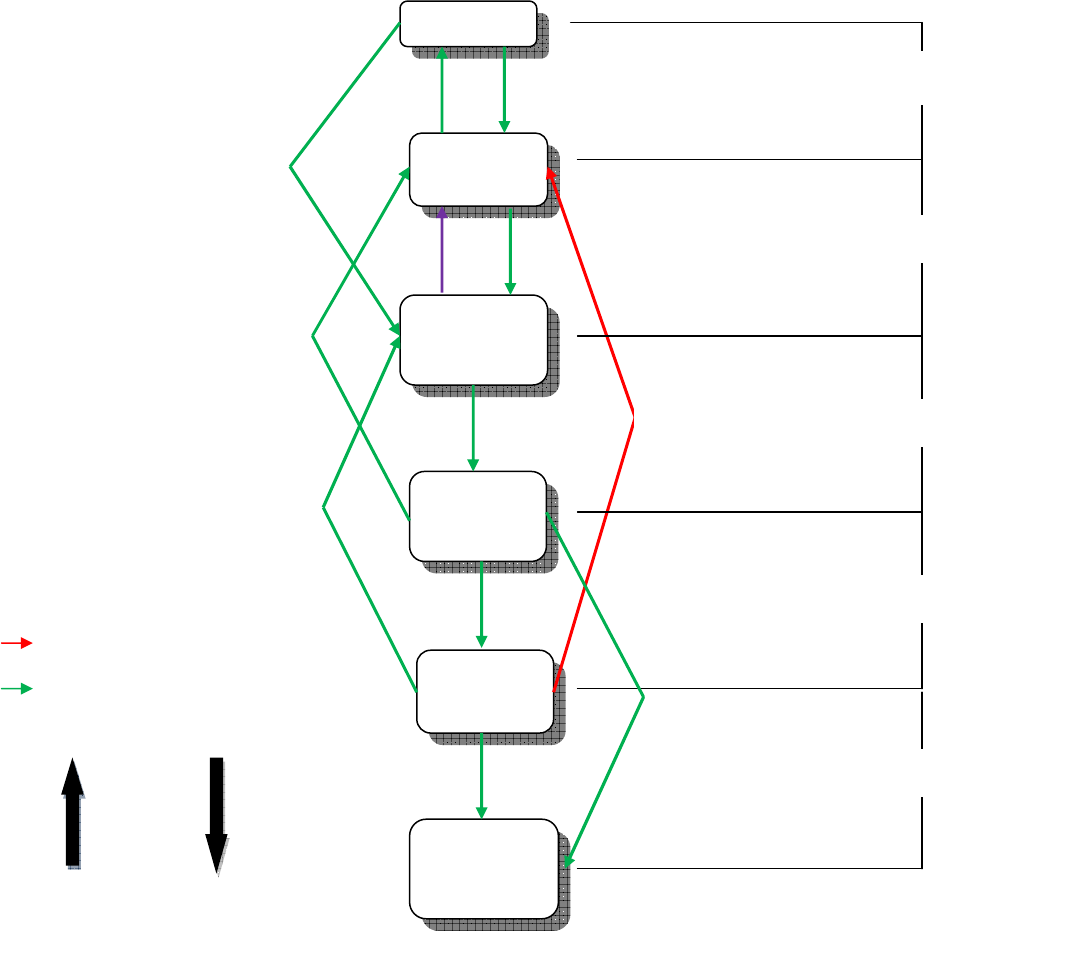
Figure 1 shows the relationships between the various tools used with forward and reverse
engineering [1]. The extreme right indicates the tools that take the software from one phase to
another. The nodes indicate the language or level of the code at that particular phase. The arrows
from top to bottom relate to the software life-cycle in forward engineering, and from bottom to
top in reverse engineering. This paper deals with the phase indicated by the arrow in purple.
4
Figure 1: Forward and reverse engineering
Program
Source
codes
Assembly
language
Object
code
Machine
code
End User
Application
Consists
IDE integration
Compile
Assemble
Link
Execute
Disassemble
Decompile
Advanced Decompile
Object code decompile
COMPILER
ASSEMBLER
LINKER
OPERATING SYSTEM
Forward
Engineering
Achievable
LEGENDS
FLOW
Difficult & Limited
Reverse
Engineering
Execute
Compile
IDE

5
2.2 Windows portable executable file format
Portable executable (PE) is a Microsoft-defined file format for the executables in the Windows
operating systems. It contains the required information for a loader to manage executable code in
the windows environment [12]. The linker gets its information regarding sections and headers
from the PE file – the information contained in the PE file decides how the linker loads the file
into memory during execution. PE consists of two types of section, the .data section and the
.code section (also known as .text section) [12]. Each section possesses its own memory
attributes that define whether data is shared between different processes, whether the section
contains code, and read–write access. It also consists of more information stored in headers, such
as the PE header, DOS header, and section table, which are required for the execution of the
program [12]. However, that information is not relevant to our research, and so is not discussed
here.
.data section
The .data section is one of the very important sections of the PE file format, containing
information about the static and global variables that were initialized in the source code. It is a
fixed-size section – like the .code section in the PE file – because the information stored in the
.data section is defined by the programmer before the code is compiled. All of the constants and
static variables used in the source code are stored in the .data section [12]. The .data section also
contains resources and relocations, API imports, and exports tables. The .data section is not read
because the values stored in the variables are likely to change during the execution. The example
below explains this phenomenon:
int i[] = {1,2,3,4,5};
int j = 6;
void main(){
char * test = “Hello World”;
int x = 5;
int* k = &x;
}
Code 1: C code for understanding read/write access of .data section
6
Integers i and j defined outside of the main will be stored in the data section as read-write,
whereas the string literal, “Hello World,” and integer value 5 will be stored as read only. The
pointer variables test and k will be stored in the read-write area.
.code section (.text section)
The .code section is a crucial section of the program that contains executable assembly
instructions. It is a fixed-size section, but – unlike the .data section – the .code section is read
only. However, the architecture supporting the self-modifying code can remove the read-only
constraints of this section, and this functionality allows for virus programming [1]. The position-
independent code of this section can be shared in memory across various processes. This section
is the most interesting section in reverse engineering, as it contains the actual logic and code
behind the software [14]. Hence, it becomes the source of input for the decompilation process.
The input to the algorithm discussed in this paper is the code section extracted from the PE.
2.3 Assembly language
The decompiling process starts from the machine code or the assembly code, with source code as
the final output. Even if it is a machine code decompiler, decompiling from machine code to
assembly code is much simpler than the second stage, which is the conversion of assembly code
to high-level language [4]. Hence, this section deals with the basic introduction of the assembly
language and x-86 instruction set.
Assembly language is a low-level language for programming hardware like the CPU, integrated
chips, and microcontrollers [7]. An assembly language is simply a machine-specific and non-
portable symbolic representation of the underlying machine code that can be interpreted by a
machine [7]. The symbols are called mnemonics, and are designed by the manufacturer of the
hardware. An assembler is basically a utility that does the same job as a compiler does for high-
level languages [8] – it translates the mnemonics into respective binary sequences. Higher-level
assemblers, like those installed in computers, convert assembly instructions into object code
rather than machine code. The object code consists of opcodes for all assembly instructions,
instead of the binary sequence [8]. This approach is adopted because of the large amount of
7
instruction sets for computers compared to other devices. Some of the notable assemblers are
MIPS, SPARC, and x86. This paper deals with the latter, x86.
x86 Assembler
This assembler is based on the 8086 assemble architecture of the Intel processor. It is supported
by Intel, AMD, and VIA processor-based systems. Operating systems like Windows, Linux, and
MAC-OSX support this assembler as well. Two versions – x86(32) 32-bit, and x86(64) 64-bit –
are available based on the processor cores [8].
x86 performs two passes on an assembly code. The first pass parses the source code to create a
table with all the unresolved symbols. The second pass uses this information to resolve the
address. This architecture lets you use undeclared symbols in your code, as opposed to one-pass
assemblers which do not [8].
x86 Instruction Set
The x86 instruction set is designed for Intel and AMD processors, and is backwards-compatible
with the following previous versions designed by Intel: 80186, 80286, 80386 and 80486 [8].
x86 processors use different registers for storing values [7]. They are,
• Special registers AX, BX, CX, and DX
• IP (Instruction Pointer)
• Flags like carry, sign, zero, and many others.
• Segment registers CS, DS, ES, FS, GS, and SS, for representing the six different
sections, such as Code, Data, Stack, and Extra.
x86 instructions are divided into five different categories based on their functionality:
1) Stack Instructions
• These instructions deal with the stack manipulation of the processor.
• Instructions like PUSH, POP, CALL, and RET come under this category.
2) Integer ALU Instructions
• These instructions deal with mathematical calculations, logical operations, and
shift operations.
8
• Arithmetic instructions: ADD, SUB, and MUL.
• Logical instructions, such as XOR, AND, and OR.
• Shift instructions: ROL, ROR, RCL, and RCR.
3) Floating Point Instructions
• These instructions deal with more complex mathematical operations, like
square root, division, and modulo, with floating point.
4) SIMD Instructions
• These instructions can perform several calculations in parallel in SIMD
registers. These are supported by modern x86 processors only.
5) Data Manipulation Instructions
• These instructions are used for accessing the data in the memory from the
different sections using various addressing modes.
• MOV, ENTER, and LEAVE
Assembly instruction format
Each line of code in the assembly language is one instruction. This pass reads it as a string. All
assembly instructions follow a specific format, unlike high-level programming language. This
format consists of four sections that are common throughout the whole assembly code:
Figure 5.1: Assembly Instruction Format
Each string contains,
1) Memory location
2) Assembly instruction
3) Operand 1 (optional)
4) Operand 2 (optional)
Figure 2: Assembly instruction format
9
3. Decompilation
In the previous chapter we discussed the fundamentals of forward and reverse engineering.
Decompilation is a process of reverse engineering, and the main focus of this research. This
chapter focuses on the benefits and problems of decompiling, and the types of decompilers and
present available tools. Decompilation is, and always will be, unable to achieve a 100% success
rate, because of many factors discussed in later sections [1] [3] [4]. There are many different
compilers available today for a programming language [32][23]. Each is implemented to handle
the source code differently in order to produce the most optimized assembly code for the
underlying machine. In addition, high-level programming languages are growing faster and
faster compared to their origins, with the inclusion of more libraries to build complex software to
satisfy new and growing requirements [23].
The most important requirement expected from a decompilation process is the human readability
of the decompiled output [3]. Often, the assembly code is too difficult to understand even for the
developer of the source code himself. Even the assembly code of a small application like “Hello
World” would take a few minutes to understand. The output of this process should be much
smaller than the assembly code, and should not contain any irrelevant details of the hardware,
memory access, or operating system interactions. There is not a tool, yet, to achieve all of these
requirements [1].
3.1 Benefits of Decompiling
Even if the results of the decompiling process are not fully accurate to the original source code,
there are some benefits to this process as well. These benefits apply to three categories,
depending upon their application [1].
1) Analyzing
2) Error checking and Evaluation
3)
Updating and Optimization
10
Analyzing
Reverse engineered source code can be used to learn the underlying algorithm and design
principles incorporated in the program [1]. This information can be used to develop a new code
with a better design and more efficient algorithm. Even if the software uses a very powerful
security algorithm at high-level programming, the most complex part of the algorithm when
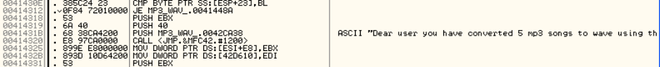
compiled to assembly code is converted to a series of granular-level instructions [9]. To
overcome this security, a hacker needs to change only a very few instructions. As in this
example, by only changing one assembly instruction the hacker could make the number of free
trials offered by the software unlimited.
Figure 3: Assembly code snippet of an algorithm checking the number of free trials used in the software
The decompiler can help the developer to understand this assembly language, and therefore to
program accordingly at high level. The developer can make the required changes to protect the
vital information in the assembly code.
Error checking and Evaluation
There are several bugs that remain undetected in high-level programming languages that can be
discovered by a careful analysis of the registers and stacks while debugging the assembly
language [10]. Infusing a viral code into the empty sections of an executable is a very common
method of attack used by virus developers around the globe. The decompilation process can help
distinguish foreign code from the original source code. A good example of this would be Cheat
Engine, an auto-assembler tool for injecting code into running processes that supports the x86
assembly instruction set. Cheat Engine is used in multiplayer gaming clients to manipulate player
levels and awards.
An ideal decompiler would produce the identical source code of two different assembly
languages having the same logic [4]. This feature could be used to detect copyright

11
infringements. Other applications for the decompiler include bug fixes, finding vulnerabilities,
interoperability, signature detection, and code comparison.
Updating and Optimizing
When source code is compiled, the compiler performs a number of optimizations on the code to
achieve the best performance from the machine. The reversed source code can be studied to
understand the optimizations performed by the compiler [1]. This information is helpful in
optimizing the code in high-level programming language itself. Also, possible modules that need
new updates and optimizing can be checked. Considering the following code:
if (4>5){
printf (“This will never execute”);
}
Code 2: Unoptimized high-level code
The compiler will remove the above code when generating the assembly code, as this if
statement is logically incorrect and execution will never print the statement.
3.2 Decompiler problems
Most of the decompiling tools in use today face common problems. In this section, we discuss
the major problems of this process, considering C as both the original source language and the
target language. These problems make the decompilation process impossible because of the way
high-level languages are structured. Overcoming such problems requires a change in the process
of forward engineering.
3.2.1 Information loss
The compiler performs code optimization, semantic analysis, lexical analysis, code generation,
and preprocessing. As a result, a great deal of information embedded in the source code is lost.
This information can be manually handled, but reversed code loses the originality and feel of the
source code. Information lost during compilation is as follows:
1) Complex mathematical expressions

12
2) Global and local variable names
3) Object-oriented code
4) High-level programming syntax
5) Structural programming
6) Comments
7) Data types
The below example consists of original C code and compiler-generated assembly code. It
demonstrates the substantial loss of information in compilation described above.
Original C code
void __cdecl Test2a ( int a, int b )
{
if ( a < b )
printf ( "a < b\n" );
else
printf ( "a >= b\n" );
}
Code 3: Code before compilation
Assembly code
01141250 push ebp
01141251 mov ebp,esp
01141253 sub esp,40h
01141256 push ebx
01141257 push esi
01141258 push edi
01141259 mov eax,dword ptr [ebp+8]
0114125C cmp eax,dword ptr [ebp+0Ch]
0114125F jge 01141271
01141261 push 1145720h
01141266 call dword ptr ds:[1148248h]
0114126C add esp,4
0114126F jmp 0114127F
01141271 push 1145728h
01141276 call dword ptr ds:[1148248h]
0114127C add esp,4
0114127F pop edi
01141280 pop esi
01141281 pop ebx
01141282 mov esp,ebp
01141284 pop ebp
01141285 ret
Assembly code 1: Example of assembly code depicting information loss

13
3.2.2 Separation of .code and .data sections
A high-level programming language consists of two sections, .code and .data. Both are
seamlessly merged throughout the code. Consider a code section as the core logic involving math
operations, and a data section as variable values, strings, and constants [10]. When compiled, the
assembly code separates this information into two different sections before embedding it into a
portable executable. The data section is then referred to by the code section of the assembly
through the memory address where this data is stored. It is difficult to merge these two sections
to their original form during the decompilation process [1] – the unavailability of the
corresponding data of the code section requires assumptions in the process, and hence the output
generated is not reliable. These problems arise because C follows an approach of defining all
items before using them. The compiler then knows what to extract from the source code for the
data section.
Consider the following C code, in which the data contained in the string passed to printf is
unavailable in the code section of the respective assembly language. This function call is
converted to call dword ptr ds:[1148248h]
in the assembly code.
Original C code
void test ( int a, int b )
{
if ( a < b )
printf ( "a < b\n" );
}
Code 4: C code example containing data within code
Assembly code
01141210 push ebp
01141211 mov ebp,esp
01141213 sub esp,40h
01141216 push ebx
01141217 push esi
01141218 push edi
01141219 mov eax,dword ptr [ebp+8]
0114121C cmp eax,dword ptr [ebp+0Ch]
0114121F jge 0114122F
01141226 call dword ptr ds:[1148248h]
0114122C add esp,4
0114122F pop edi
01141230 pop esi
01141231 pop ebx
01141232 mov esp,ebp
01141234 pop ebp
01141235 ret 8
Assembly code 2: Loss of data in .code section

14
3.2.3 Differentiating original pointers from address offsets
Assembly language is ambiguous in differentiating between the actual pointer variables – used to
store an address or the starting address of a dynamic memory allocation in a high-level code –
and the offset pointers that point to an address offset from the actual pointer [1].
Consider the following 2 cases:
Pointer offset outside the bounds of array
int numbers [5] = {1, 1, 1, 1, 1};
for(int i = -5, i < 0; i ++){
printf(“%d”, a + i);
}
Code 5: Code example for pointer offset outside the bounds of array
Pointer offset inside the bounds of array
int numbers [5] = {1, 1, 1, 1, 1};
for(int i = -5, i < 0; i ++){
printf(“%d”, a + i + 5);
}
Code 6: Code example for pointer offset inside the bounds of array
This type of code produces the same assembly output, but when reverse engineered only the
second case will produce the closest corresponding C code to the original source code [2]. This is
because the second case is still logically inside the array index bounds, while the first case is not
at all accessing the array elements [23]. Without the compiler and linker differentiating between
the original pointer and the offset, it is impossible to determine the offset for a reverse
engineering tool just from the pointer variable [32].
3.2.4 Detecting constants from the pointers
The other major problem faced by reverse engineering tools is distinguishing pointers from
constants [1]. The operand following the assembly instruction is treated as a constant, which can
be any data type – an integer or a float. But, it can also be a pointer variable to a data stored
15
somewhere in the memory instead of the data itself. This problem can be considered as the first
hurdle towards differentiating offsets and actual pointers. Using actual data or an address from a
.data section that contains the data is decided by the compiler based on the optimization setting
[8].
3.3 Limitations
Though decompilers can be used for a variety of benefits, achieving those benefits requires
considerable manual intervention and numerous assumptions during the process. These
assumptions can sometimes lead to a faulty code and an even more complex structure. Also, if
time is a constraint, manual intervention is impossible for larger codes. The primary existing
limitations that need to be addressed while designing a decompiler are as follows: [1]
• Handling of direct or indirect function calls
• Handling of direct or indirect jump calls
• Handling type casting and recovery
• Stack pointers or memory references
• Function and variable names
• Merging code and data sections
The only advantage of reverse engineering over forward engineering is its full scope over the
entire application.
3.4 Types of Decompilers
Decompilers can be summarized into three different types. Each has its own difficulty level and
constraints. These difficulties arise based on the desired input and output [4], while constraints
are present due to the information loss and the optimizations performed by the compiler. Tools
that reverse the actions of linkers and disassemblers are currently available, with highly-
dependable results. IdaPro and OllyDbg are considered to be the best of them [4].
Many attempts and much research has suggested the use of different decompilers. However,
these tools are unable to produce results that can be compiled or even be understood by humans
[3][4]. This section categorizes different decompiler tools and gives a few examples of each. The
16
most important of these, and the one that this paper deals with, are machine code decompilers. A
more detailed explanation with results analyzed from the currently-available machine code
decompilers is also presented.
Virtual machine decompiler
A fine example of the virtual machine decompiler is the Java bytecode decompiler. The Java
bytecode decompiler has achieved a success ratio near 90%, as the Java byte is rich with
metadata to allow negligible information loss. Most of the complex information – such as
variable names, separation of code and data section, type analysis, and global data – is explicitly
visible in bytecode [1].
There exist a few challenges with the virtual machine decompiler, too, but these have already
been resolved to an extent. Optimized bytecode, code obfuscation, and subtypes of basic
datatypes are a few of these difficulties.
Virtual machine decompilers enjoy the best position because their input is rich with metadata,
which is vital for the decompiling process. Here is a list of some professional virtual machine
decompilers:
1) JAD Decompiler [28]
2) JReverse Pro [29]
3) JODE Decompiler [27]
4) McGill’s Decompiler [26]
Object code decompiler
An object code decompiler takes the machine code and generates the intermediate object files
between the machine code and assembly code [31]. Though theoretical only, these decompilers
are better than machine code decompilers but worse than assembly code decompilers in terms of
achievability [1] [3]. The object code decompiler does not benefit from much research focus, as
its final output is object code that serves no major importance in reverse engineering [1]. As
such, very few of these decompilers have been researched. The most noteworthy object code
decompilers are Winger and Schneider [30] and Decomp [31]. Both were created with very
limited functionality and for specific purposes only.
17
The machine code decompiler discussed in the next section is a multi-process decompiler. One
of its processes has the same functionality as an object code decompiler – reversing the machine
code – but the final output of a machine code decompiler is assembly code, not object code [4].
This process is beyond the scope of this paper and not discussed in detail.
Machine code decompiler
Machine code decompilers have attracted the most research from enthusiast reverse engineers
since the origin of programming language. Since these decompilers are based directly on the
underlying platform (that is, hardware), these are the most difficult decompilers to create. A
universal decompiler is also not achievable even in theory [1]. Even with the constant evolution
of high-level programming languages and the hardware that processes machine code, these
decompilers still have not reached a level to be able to extract even 10% of the original source
code [32]. The two processes of the machine code decompiler are disassembling and
decompiling, but we concentrate on the decompiling process here. A few noteworthy research
machine code decompilers are listed below. The first three are the most successful, and are
discussed in more detail later in this paper.
1) Boomerang [1]
2) Dcc [5]
3) REC [6]
4) Exec -2-C [20]
5) DisC [25]
6) DesQuirr [16]
7) Yadec [17]
8) Andromeda [18]
9) HexRays [19]
3.5 Present decompiler tools
For decompiling a portable executable compiled with most commonly-known compilers –
Borland C++, Dev C++, Microsoft Visual C++, and Turbo C – there are very few decompilers
available that perform this process with considerable success ratio [3][4]. These are Boomerang,
REC, and dcc [3]. There have been many other decompiler tools prior to this, but they were more
18
like research tools that perform only in a controlled environment. They are classified based on
their category in the next chapter. As we are interested in C code generation, only these three
most functional tools match our criteria.
Boomerang
Boomerang is an open-source machine code to C decompiler. It tries to alter the semantics of
each of the assembly instructions, and implements the Static Single Dataflow Analysis to achieve
its goal [1]. This makes it independent of the compiler optimizations performed on the assembly
code. Boomerang’s approach to this process includes implementing a very powerful internal
representation (IR), which then tries to recreate each and every step of the compiler while
parsing the assembly code. However, the results on the Hello World program were either
inefficient or not even close to the original, and the process is quite time-consuming. The
algorithm described in this paper adopts these concepts from Boomerang, but they are modified
to produce better results. The internal representation of symbols is critical for implementing a
decompiler algorithm, as the assembly code is very granular and we cannot be sure about each
symbol as we encounter them in passes.
REC
REC is a machine code decompiler that recognizes not only Win32 executables but also other
formats of Linux, Solaris, and Playstation PS-X executables. The output generated is C-like, and
requires manual editing to recompile [5]. Though the output produced by REC is very close to C
code, the decompiler has many constraints. The REC decompiler is heavily compiler-dependent,
supporting Win32 executables (portable executables) compiled by Microsoft Visual C++ 6 and
Microsoft Visual Basic 5. The algorithm relies on the information available from the executable
symbol table, which varies per compiler settings. It performs poorly if the executable is created
without debugging information files like the program data base (.pdb) or the code view (.c7).
Dcc
Dcc is a research decompiler that decompiles only 80286 DOS-based executables to C language
[6]. The Dcc approach to decompilation is based on graph theory and optimization techniques
adopted by compilers. These compiler optimization techniques eliminate high-level

19
programming constructs and generated intermediate assembly instructions using registers. Dcc
tries to follow the same approach in a reverse order. Dcc is also a three-pass decompiler, where
the first pass is a machine code decompiler that generates assembly, the second pass generates
intermediate symbol tables by performing code flow and data flow analysis, and the third pass
generates the output, which resembles C like code. The algorithm described in this paper follows
a three-pass, but the functionalities implemented at each pass are completely different from those
of this tool. The machine code decompiler is beyond the scope of this research, but graph
representation of the control flow is adopted in this paper.
Comparison of Dcc and REC
The table below compares different aspects of the two best available decompilers on a scale of 0
to 10, with 0 being the worst performance and 10 being the best [1].
Table 3: Comparison of Dcc and REC
Test Case Dcc REC
Large Executables 5
0
Parameters Handling 7
5
Handling Returns 7
5
Jumps 9
5
Function Calls 7
0
Type casting 7
0
Total 42
15
20
5. Decompiler algorithm
This section deals with the main algorithm behind the decompiling process implemented in this
paper. The algorithm is a three-pass algorithm: raw view, parsed view, and recognized view.
Raw view deals with reading the assembly language from the .DIS file. This output is still very
difficult to handle within the algorithm. Parsed view generates the vector of strings in a specific
format that can be understood by the algorithm. The third pass, recognized view, contains the
algorithm that reads one assembly line at a time and generates the pseudo C code. The algorithm
is implemented in C language using the Microsoft Visual C++ compiler. Code optimization
options of the compiler are disabled.
5.1 Initial Preparation
A wide range of test functions – including different implementations of C basic syntax like for
loop, while loop, if/else (simple and complex), switch case, and math instructions – were created
using Microsoft visual C++ compiler. Compiler optimizations were disabled for creating these
test cases, as it is trivial for the algorithm to have the complete assembly of the logic, which may
contain assembly instructions that would otherwise have been omitted by the compiler
optimization.
Calling Conventions
A calling convention is used to determine how different platforms parse different functions, how
their parameters are received and handled, and how results are returned from the function.
Different programming languages use different calling conventions. All test cases were created
using three different calling conventions: _stdcall, _cdecl, and _fastcall. These calling
conventions are provided by the Microsoft Visual C++ compiler, and are considered in this
research because they play an important role in how the assembly code handles parameters, stack
operations, and registers. The example below explains different calling conventions in detail.
First consider the below C code where XX can be substituted with _stdcall, _cdecl and, _fastcall
keywords.

21
Original C code
void XX Test1b ( int a, int b )
{
if ( a < b )
printf ( "a < b\n" );
}
Code 7: Function calling convention
1) _stdcall
Parameters passed to the function are pushed to the stack in reverse order. The function
accesses these parameters from the stack, and the stack cleans operations after the
function execution is handled by the callee.
01141210 push ebp
01141211 mov ebp,esp
01141213 sub esp,40h
01141216 push ebx
01141217 push esi
01141218 push edi
01141219 mov eax,dword ptr [ebp+8]
0114121C cmp eax,dword ptr [ebp+0Ch]
0114121F jge 0114122F
01141221 push 1145720h
01141226 call dword ptr ds:[1148248h]
0114122C add esp,4
0114122F pop edi
01141230 pop esi
01141231 pop ebx
01141232 mov esp,ebp
01141234 pop ebp
01141235 ret 8
Assembly code 3: _stdcall calling convention
2) _cdecl
This calling convention is the same as _stdcall, except that the stack cleanup operations
are performed by the caller. It is clearly visible in the example below that the function
does not return anything, as the results are stored in the stack.
011411A0 push ebp
011411A1 mov ebp,esp
011411A3 sub esp,40h
011411A6 push ebx
011411A7 push esi
011411A8 push edi
011411A9 mov eax,dword ptr [ebp+8]
011411AC cmp eax,dword ptr [ebp+0Ch]
011411AF jge 011411BF
011411B1 push 1145720h

22
011411B6 call dword ptr ds:[1148248h]
011411BC add esp,4
011411BF pop edi
011411C0 pop esi
011411C1 pop ebx
011411C2 mov esp,ebp
011411C4 pop ebp
011411C5 ret
Assembly code 4: _cdecl calling convention
3) _fastcall
_fastcall stores the parameters in the registers ECX and EDX. This type of calling
convention is used to increase the performance of the function, as register access is faster
than stack access. This convention also does not have any function returns.
011411D0 push ebp
011411D1 mov ebp,esp
011411D3 sub esp,48h
011411D6 push ebx
011411D7 push esi
011411D8 push edi
011411D9 mov dword ptr [ebp-8],edx
011411DC mov dword ptr [ebp-4],ecx
011411DF mov eax,dword ptr [ebp-4]
011411E2 cmp eax,dword ptr [ebp-8]
011411E5 jge 011411F5
011411E7 push 1145720h
011411EC call dword ptr ds:[1148248h]
011411F2 add esp,4
011411F5 pop edi
011411F6 pop esi
011411F7 pop ebx
011411F8 mov esp,ebp
011411FA pop ebp
011411FB ret
Assembly code 5: _fastcall calling convention
5.2 Algorithm
Figure 4 depicts the flowchart of the decompiler algorithm explained in this paper. All three
different passes and their sub-modules are explained in further sections of this chapter. The
background information required to understand this algorithm has been provided in previous
chapters. Each of these passes is explained with one test case.

23
Figure 4: Decompiling algorithm flowchart

24
5.1 First Pass – Raw view
This pass deals with reading the assembly language from the .dis file and storing it in a vector of
strings. Each string is one assembly instruction read from the file in the specific format of
memory address, assembly instruction, operand 1, and operand 2. Each instruction follows this
specific format and order, and hence can easily be read using regular expressions. Instruction
prefixes and three-operand instructions are currently unsupported. Operand 1 and operand 2 are
separated by a comma delimiter, and operand 2 is optional for some instructions. This pass
detects if the input assembly file contains any errors. If so, the algorithm is terminated and a
corresponding error message is displayed.
5.1.1 Raw view example
This section describes an example of the complete run of this pass along with the format in
which the assembly instruction is read.
Consider the following input assembly code:
011411A0 push ebp
011411A1 mov ebp,esp
011411A3 sub esp,40h
011411A6 push ebx
011411A7 push esi
011411A8 push edi
011411A9 mov eax,dword ptr [ebp+8]
011411AC cmp eax,dword ptr [ebp+0Ch]
011411AF jge 011411BF
011411B1 push 1145720h
011411B6 call dword ptr ds:[1148248h]
011411BC add esp,4
011411BF pop edi
011411C0 pop esi
011411C1 pop ebx
011411C2 mov esp,ebp
011411C4 pop ebp
011411C5 ret
Figure 5: Raw view input
The algorithm reads the assembly code line-by-line to the end of file, in order to generate a
vector of strings in the format shown below:
Table 4: Assembly instruction string format
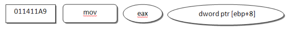
Memory address Instruction Operand 1 Operand 2
011411A9 mov eax dword ptr [ebp + 8]

25
5.2 Second Pass – Parsed view
This pass deals with generating an intermediate representation from the raw view for the
algorithm, which is very easy to handle and manipulate by logic during the recognized view. The
output of raw view consists of a vector of strings that is very difficult to handle in programming
logic because it involves string manipulation functions. This step takes the vector of strings as
input and generates an IR better suited for the algorithm to understand the input assembly and to
generate the pseudo C output. This step has no major role in the core logic of the decompilation
process, but it makes the algorithm more robust and increases overall performance.
This step performs three major operations on the assembly code from the raw view. They are
explained below in the order they are performed.
Conversion of vector strings to structures
The raw input consists of strings corresponding to each assembly instruction from the initial
input. These strings contain the most important details that will be used by the recognized view.
However, handling the strings in a complicated algorithm can be very tedious and non-
optimized programming; so, this step tries to solve this problem by converting each string into a
C structure that can then be used in the logic very efficiently. The structure of this C struct is as
follows:
typedef struct _RECOGNIZED_INSTRUCTION
{
ULONG_PTR AbsoluteAddress;
ULONG_PTR RelativeAddress;
UINT InstructionId;
OPERAND Operand1;
OPERAND Operand2;
} RECOGNIZED_INSTRUCTION, *PRECOGNIZED_INSTRUCTION;
Code 8: Recognized instruction C structure
Relative Addressing
From the previous section, we have seen that an assembly instruction contains a memory
location. This memory location is the actual location of that instruction when the executable is
loaded into memory. These locations are of critical importance to the algorithm because the

26
assembly language processes loops and execution flows based on these addresses. The memory
location of the successive instruction is added to the instruction size of the previous instruction;
so, it can be derived that the memory locations are successive in memory. Their initial starting
point depends on the operating system, and is likely to change on every execution run. But,
since this algorithm focuses on decompilation on a smaller scale, those factors are not of much
concern.
The locations are eight digits long, but the first half will likely be the same for each instruction
unless the executable is very large. Again, this is constrained in our algorithm, so the important
parts from the location for our algorithm are the lower-order bits. Since the input assembly is not
the complete assembly of the executable, but only the section of it that we are interested in
decompiling, the actual address can be replaced by the relative address as long as we preserve
the instruction size.
Instruction ID
The algorithm covers a specific set of instructions from the Intel x86 instruction manual [12].
This step assigns a constant value to each of the instructions in the raw view. Assigning an
integer value to the string helps us to identify the instruction in the complex logic through
conditions rather than string comparisons. The raw view pass has already detected if the code
consists of unsupported instructions – the execution reaches this pass only with supported
instructions. The instructions supported by the algorithm are as follows:
Table 5: Supported assembly instructions
Functionality Instructions
Math Operations
Fld, Fadd, Fstp, Fsub, Fmul, Fdiv, Imul,
Add, Sub
Stack Operations Push, Pop
Function Operations Ret, Call
Jump Operations Ja, Je, Jle, Jge, Jne, Jmp
General-Purpose Operations Cmp, Mov
27
5.2.1 Parsed view example
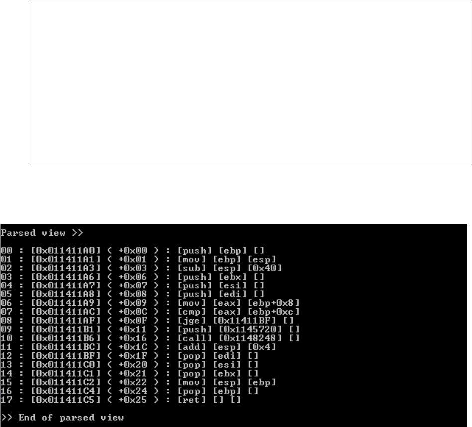
This example shows the changes made by parsed view to the input assembly code:
Input assembly code to the parsed view
011411A0 push ebp
011411A1 mov ebp,esp
011411A3 sub esp,40h
011411A6 push ebx
011411A7 push esi
011411A8 push edi
011411A9 mov eax,dword ptr [ebp+8]
011411AC cmp eax,dword ptr [ebp+0Ch]
011411AF jge 011411BF
011411B1 push 1145720h
011411B6 call dword ptr ds:[1148248h]
011411BC add esp,4
011411BF pop edi
011411C0 pop esi
011411C1 pop ebx
011411C2 mov esp,ebp
011411C4 pop ebp
011411C5 ret
Assembly code 6: Parsed view input
Output generated by parsed view
Figure 6: Parsed view output
5.3 Third Pass – Recognized view
This pass contains the core logic of the algorithm and deals with parsing the parsed view and
creating pseudo C code. This process can be broken down into a number of steps, each
28
performing different specific operations from the input received from the previous step. Each
decompilation process in the algorithm follows these steps:
1) Stack initialization and analysis
2) Register initialization and analysis
3) Graph generation
4) Output generation
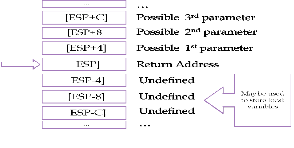
5.3.1 Stack initialization and analysis
Each function call in the assembly language generates a few stack instructions before executing
the function logic. These stack instructions contain important information – calling convention
used, number of parameters, and their values and function return location. This step analyzes
these instructions and captures the most important information needed for the further steps in the
algorithm.
The initialization of the stack structure helps us to determine our calling convention and
parameter information.
Figure 7: Stack initialization
29
The use of ESP determines whether the calling convention used was _cdecl or _stdcall, but it
cannot still be determined as differentiating them based on the RET instruction. As in the _cdecl
calling convention, the caller cleans up the stack after a successful function call; in _stdcall, the
callee pops the parameters from the stack. Also, each parameter passed to the stack takes 4 bytes
of memory space. This helps us determine the number of parameters used in the underlying
logic. The space below the stack pointer helps us determine the number of local variables created
by the function.
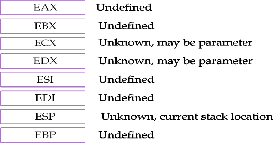
5.3.2 Register initialization and analysis
Intel x86 uses eight general purpose registers for executing assembly instructions. These
registers are used by the processor for an immediate reference, as accessing these registers is
faster than physical memory. The analysis of these registers helps determine the _fastcall calling
convention and the intermediate values used while performing the calculation. The _fastcall
calling convention uses ECX and EDX registers for storing the parameters passed to the
function. EAX and EBX are used for immediate calculation and storing intermediate values [12].
We recorded the states of each register during the course of the algorithm whenever the assembly
instruction refers to keywords related to registers. The initialization of the registers is as follows:
Figure 8: Register initialization
30
ECX and EDX help determine the parameters passed to the function and the calling convention
used, while EAX and EBX are useful during analysis of the loop counters and other immediate
variables used in the assembly instruction.
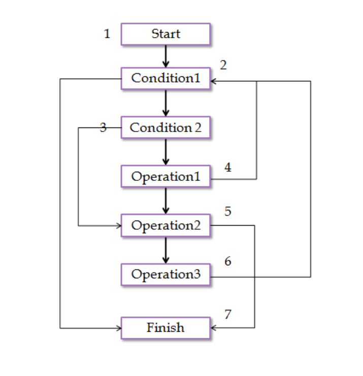
5.3.3 Graph Generation
This is the most critical and essential part of the algorithm, determining the high-level
programming language syntax from the underlying assembly language. This step reads the most
steps of the raw view at a single time compared to any other steps in the algorithm, and hence is
the most important step of this research paper.
Each supported assembly instruction has a function handler, which contains the logic on how to
handle the specific assembly instruction. Some assembly instructions are standalone, and are
most equivalent to their respective C instructions in terms of granularity – for example, MOV.
However, most assembly instructions are highly dependent on further instructions to provide
simple instructions in high-level programming language. Each of these function handlers
contains the logic on how to handle its own assembly instruction, and each handler sets the flags
accordingly for the further steps of the algorithm.
Based on the information returned from these function handlers, the next process helps us
determine the more complex C syntaxes, like loops. This step generates dependency graphs and
semantic loads by virtually executing each assembly instruction [10]. The semantic load helps us
to determine the loop counters, and dependency graphs determine the type of structure of
execution, like for loop, switch, or if/else. We do not differentiate between for loops and while
loops, since that information is lost during compilation – all for loops can be represented by
while loops, so this is not a major constraint to this step. Figure 9 shows the different function
handlers implemented into this algorithm. The algorithm is designed in this manner to allow easy
implementation of support for more instructions in the future. Any instruction to be supported in
this algorithm must have a function handler defined in this section of code, and the logic to be
implemented in its function handler.

31
static INSTRUCTION SupportedInstructions[] =
{
{ L"add", AddHandler },
{ L"call", CallHandler },
{ L"cmp", CmpHandler },
{ L"ja", JaHandler },
{ L"je", JeHandler },
{ L"jge", JgeHandler },
{ L"jle", JleHandler },
{ L"jne", JneHandler },
{ L"jmp", JmpHandler },
{ L"imul", ImulHandler },
{ L"mov", MoveHandler },
{ L"pop", PopHandler },
{ L"push", PushHandler },
{ L"ret", RetHandler },
{ L"sub", SubHandler },
{ L"fld", FldHandler },
{ L"fadd", FaddHandler },
{ L"fstp", FstpHandler },
{ L"fsub", FsubHandler },
{ L"fmul", FmulHandler },
{ L"fdiv", FdivHandler }
};
Code 9: Supported instructions' function handlers
Every assembly instruction is treated as a vertex of the graph, and execution flow can be
considered an edge to build this dependency graph [21]. The beginning and end of the function
are also considered vertexes. We do not consider the stack and register operations, as they are
already handled by the previous steps of this pass. We use this graph to build the incidence list.
Below is the complete example of original C code with nested if along with the respective
dependency graph and incidence list and its interpretation:
Original C code
If(a > 4){
If( a != 5){
Foo();
}
}Return;
Code 10: Nested if

32
Dependency graph for nested if
Figure 9: Nested if dependency graph
This graph can help us build the incidence lists. Incidence lists are very convenient for
recognizing high-level programming structures [22]. The incidence list for the above graph
would be,
(1, 2)
(2, 3), (2, 5)
(3, 4), (3, 5)
(4, 5)
Interpretation of incidence list
(2, 3), (2, 5) represents if condition a>5
(3, 4), (3, 5) represents the nested if condition a != 5
(4, 5) represents the end of the if condition with both if clauses satisfied
33
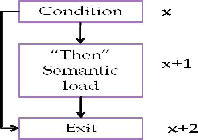
If-then detection
If the case is only if-then, then we have a different graph compared to mixed if-then and nested
ifs. In order to identify if-then, we have to detect the following graph pattern and ensure that
there is no external reference to (x+1).
Dependency graph
Figure 10: If-then dependency graph
Incidence list
(x, x+1)
(x, x+2)
(x+1, x+2)
Interpretation of incidence list
(x, x+1) represents inside the if condition
(x, x+2) represents outside the else condition
(x+1, x+2) represents the end of the if condition with the if clause dissatisfied
34
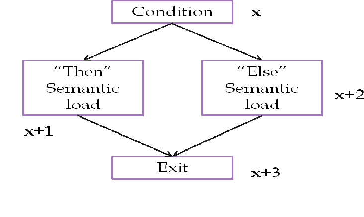
If/else detection
Detecting if/else is very similar to previous cases, except for the difference in the incidence list.
If we have an if/else inside an if, that makes a compound if statement and we can replace two
if/elses with one condition. We must do that to eliminate all ifs.
Dependency Graph
Incidence list
(x, x+1)
(x, x+2)
(x+1, x+3)
(x+2, x+3)
Interpretation of incidence list
(x, x+1) represents inside the if condition
(x, x+2) represents inside the else condition
(x+1, x+3) represents the end of the if/else with the if condition satisfied
(x+2, x+3) represents the end of the if/else with the else condition satisfied
Figure
11
: Dependency graph for if/else
35
Loop detection
Loops primarily create three graphs based on three types of loops: the normal loop, continue
loop, and break loop. Normal loops consist of top-to-down direction graphs, but the edge from
the last node leads to the start node. The start node also has an edge leading to finish node based
upon the condition. This case is similar in all type of loops.
Continue loops have an edge going from the middle nodes to the start node, while break loops
have an edge going from the middle nodes to the outside of the loop nodes. Figure 12 depicts a
for loop with an if/else statement that contains the switch and break cases. This helps us to
determine the difference in detecting these loops.
Factors like conditions and loop counters have already been handled by the function handlers in
the previous step.
Dependency graph
Figure 12: Dependency graph for loop
36
Incidence list
(1, 2)
(2, 3), (2, 7)
(3, 4), (3, 5)
(4, 5), (4, 2)
(5, 6), (5, 7)
(6, 2)
Interpretation of the incidence list
(2, 3), (2, 7) represents the for loop condition
(3, 4), (3, 5) represents the if/else condition
(4, 5), (4, 2) represents continue
(5, 6), (5, 7) represents break
(6, 2) represents one loop iteration
Switch detection
Switch case statements are similar to if/then statements. However, if the code consists of
multiple ifs accessing the same variable, it is very difficult to determine the difference between
them as they will produce the same dependency graph. The switch is detected if the graph
consists of a vertex with many outgoing edges to different nodes, which then have outgoing
edges to a finish node. The default case can be detected, as there will be an edge with no
condition. Figure 13 on the next page depicts the dependency graph.
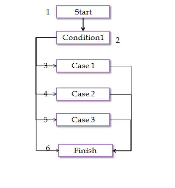
37
Dependency graph
Incidence list
(1, 2)
(2, 3), (2, 4), (2, 5), (2, 6)
(3, 6)
(4, 6)
(5, 6)
Interpretation of the incidence list
(1, 2) represents the switch condition
(2, 3), (2, 4), (2, 5), (2, 6) represents different cases
(3, 6) represents the end of the switch case with case 1 satisfied
(4, 6) represents the end of the switch case with case 1 satisfied
(5, 6) represents the end of the switch case with case 1 satisfied
Figure 13: Dependency graph for switch case
38
5.3.4 Output generation
This step produces the final output of the algorithm: the pseudo C code. The major functions of
this step include variable naming, syntax structuring, and filling the information gaps left over
from the previous steps. This step does not involve much complicated logic, as much of the
information necessary to complete this step is available from the previous steps.
Variable naming
The register-analyzing and stack-analyzing steps help us to determine the number of parameters
passed to this function or the number of local variables created. Retrieving the original variable
names is not possible in this process, so we assign new variable names to our newly-found
variables. The naming convention names them according to “ParamXX,” where XX stands for
increasing order – 00, 01, 02.
Function definition
We obtained the information about the function calling convention and parameters from the
previous steps. Determining the function return type is currently not within the scope of this
project. This step creates the function prototype based on the information we have acquired.
Syntax structuring
The graph generation phase has already provided the high-level programming logic of the
reversed assembly code. Now, this step handles the parenthesis “{“ and “}” around this code,
relying on regular expressions and flags from the previous steps.
Gap filling
Some assembly codes that refer to a different memory location outside of input through the use
of CALL functions are not possible to decompile with this algorithm. Library or system function
references are examples of this – they are represented in the output by their same assembly
instruction.
39
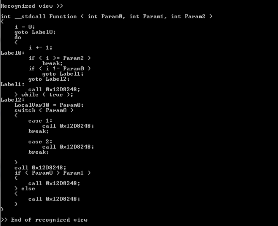
5.3.5 Output
Below is the final output created by the algorithm. This example consists of three parameter
inputs, for loop, switch case, and if-then-else. The output has the look and feel of a C code, and
is more understandable than related assembly code. Printf statements are represented by call
instructions to the related address in data section.
Figure 14: Recognized view output

40
6. Test cases and Results
In this section we discuss a complete test case along with its results. More test cases with
different original code syntaxes and structures are provided in Appendix A. This particular test
case consists of for loop, switch case, and if/else in the original code. The compiler used to
compile test cases is Microsoft Visual C++, and the assembler is Microsoft x86 Assembler.
Optimization has been disabled for generating the test cases. The original C code, generated
assembly code, and decompiler-generated output is provided below:
Original Code
void __fastcall Test14b ( int a, int b, int c )
{
for ( int i = 0; i < c; i++ )
{
if ( i == a )
break;
printf ( "loop" );
}
switch ( a )
{
case 1:
printf ( "a = 1\n" );
break;
case 2:
printf ( "a = 2\n" );
break;
}
printf ( "in the middle\n" );
if ( a > b )
printf ( "a > b\n" );
else
printf ( "a <= b\n" );
}
Code 11: Test case C code

41
Assembly Code
012D2320 push ebp
012D2321 mov ebp,esp
012D2323 sub esp,50h
012D2326 push ebx
012D2327 push esi
012D2328 push edi
012D2329 mov dword ptr [ebp-8],edx
012D232C mov dword ptr [ebp-4],ecx
012D232F mov dword ptr [ebp-0Ch],0
012D2336 jmp 012D2341
012D2338 mov eax,dword ptr [ebp-0Ch]
012D233B add eax,1
012D233E mov dword ptr [ebp-0Ch],eax
012D2341 mov eax,dword ptr [ebp-0Ch]
012D2344 cmp eax,dword ptr [ebp+8]
012D2347 jge 012D2363
012D2349 mov eax,dword ptr [ebp-0Ch]
012D234C cmp eax,dword ptr [ebp-4]
012D234F jne 012D2353
012D2351 jmp 012D2363
012D2353 push 12D5870h
012D2358 call dword ptr ds:[12D8248h]
012D235E add esp,4
012D2361 jmp 012D2338
012D2363 mov eax,dword ptr [ebp-4]
012D2366 mov dword ptr [ebp-50h],eax
012D2369 cmp dword ptr [ebp-50h],1
012D236D je 012D2377
012D236F cmp dword ptr [ebp-50h],2
012D2373 je 012D2387
012D2375 jmp 012D2395
012D2377 push 12D5854h
012D237C call dword ptr ds:[12D8248h]
012D2382 add esp,4
012D2385 jmp 012D2395
012D2387 push 12D5840h
012D238C call dword ptr ds:[12D8248h]
012D2392 add esp,4
012D2395 push 12D5880h
012D239A call dword ptr ds:[12D8248h]
012D23A0 add esp,4
012D23A3 mov eax,dword ptr [ebp-4]
012D23A6 cmp eax,dword ptr [ebp-8]
012D23A9 jle 012D23BB
012D23AB push 12D5734h
012D23B0 call dword ptr ds:[12D8248h]
012D23B6 add esp,4
012D23B9 jmp 012D23C9
012D23BB push 12D5784h
012D23C0 call dword ptr ds:[12D8248h]
012D23C6 add esp,4
012D23C9 pop edi
012D23CA pop esi
012D23CB pop ebx
012D23CC mov esp,ebp
012D23CE pop ebp
012D23CF ret 4
Assembly code 7: Test case assembly code
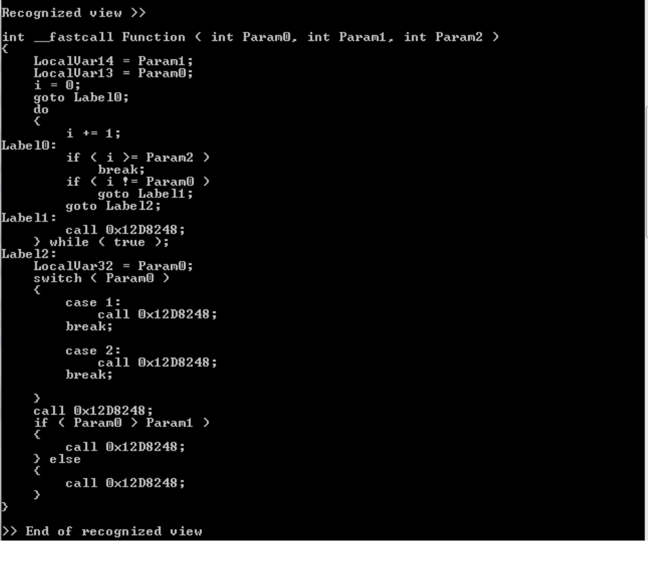
42
Decompiler-Generated Output
6.1 Comparison with manual decompilation
This test case involves manually decompiling assembly code and comparing it with the
algorithm-generated output. The assembly code was provided to a user with some assembly
language knowledge, who was then asked to generate a C code. The test case chosen was quite
simple, containing only an if/else. The original C code, assembly code, manually-generated code,
and decompiler-generated output are provided below:
Figure 15: Decompiler-generated output

43
Original Code
void __cdecl Test2a ( int a, int b )
{
if ( a < b )
printf ( "a < b\n" );
else
printf ( "a >= b\n" );
}
Code 12: if/else original C code
Assembly Code
01141250 push ebp
01141251 mov ebp,esp
01141253 sub esp,40h
01141256 push ebx
01141257 push esi
01141258 push edi
01141259 mov eax,dword ptr [ebp+8]
0114125C cmp eax,dword ptr [ebp+0Ch]
0114125F jge 01141271
01141261 push 1145720h
01141266 call dword ptr ds:[1148248h]
0114126C add esp,4
0114126F jmp 0114127F
01141271 push 1145728h
01141276 call dword ptr ds:[1148248h]
0114127C add esp,4
0114127F pop edi
01141280 pop esi
01141281 pop ebx
01141282 mov esp,ebp
01141284 pop ebp
01141285 ret
Assembly code 8: Assembly code if/else
Manually-Generated C Code
void test ( )
{
int i, j;
if ( i < j )
do something;
if ( i > j )
do something;
}
Code 13: Manually-generated output
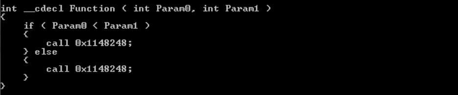
44
Decompiler-Generated C Code
Figure 16: Decompiler-generated output
Analysis
As we can see, the user was unable to determine the calling convention used for the function call.
As a result, the user was unable to find the number of parameters passed to the algorithm, and
this leads to the assumption of two local variables i and j. Also, the original syntax of if/else was
not replaced by two simple ifs, and the user was unable to determine the details inside the if
statements.
45
8. Future Work
From this research, we can conclude that decompilation is a very complicated process, and is
constrained by a number of limitations. The proposed algorithm tries to implement some of the
concepts in the above-mentioned process in a very effective way. However, many improvements
could still be added to this algorithm for a more successful reversing process and to cover more
assembly instructions.
More complicated assembly instructions
If other assembly instructions that are more complicated and not covered in this paper could be
added to this algorithm, it could improve the reversing of highly-complicated code. The
algorithm is adaptable to the addition of other instructions by adding them to the function
mapping and implementing the corresponding functionality of that instruction in its relative
function. If the assembly instruction to be added is more dependent on execution flow of the
code, then it would require a considerable amount of testing with the assembly to determine the
changes in dependency graphs created by these instructions [7].
Instructions that are standalone or that do not affect the execution flow can easily be
implemented with the above approach. Before adding the implementation of the assembly
instructions, the instruction’s impact on the output code needs to be studied deeply. Some
assembly instructions are created specifically for hardware operations that do not have
corresponding high-level language implementations. Decompilation algorithms are heavily based
on assumptions [1] [3], but we would like to keep the assumption factor of the algorithm as low
as possible. One possible way to achieve this is by not adding extra support for instructions that
do not play a major role in the related output.
Handling the data section with the code section
This algorithm is currently limited to handling only the .code section of the assembly language.
Future work could include modifying the algorithm to handle both the .data section and the .code
section [12]. This could help to achieve the constants and values used in high-level language.
46
This feature can retrieve the strings and other data that gets separated from the code section
during the compilation process [15].
Inbuilt disassembler
The current scenario takes the .dis file as an input and generates a text C file. If a further step to
disassemble – that is, reversing the machine code to the assembly code from an executable file –
is added to the algorithm, we could avoid the manual file creation of the .dis file. Also, the
algorithm would have more information, along with all the sections that it currently lacks.
Object oriented code and user interface
These two topics have been the least touched on in this process, as reversing them is extremely
complicated and mostly unreliable in terms of the output generated. The assembly code removes
the concept of the object oriented code when it is compiled [7], and the UI code is handled by the
system calls. With different compiler settings and a controlled environment, we could still
attempt to overcome these barriers.
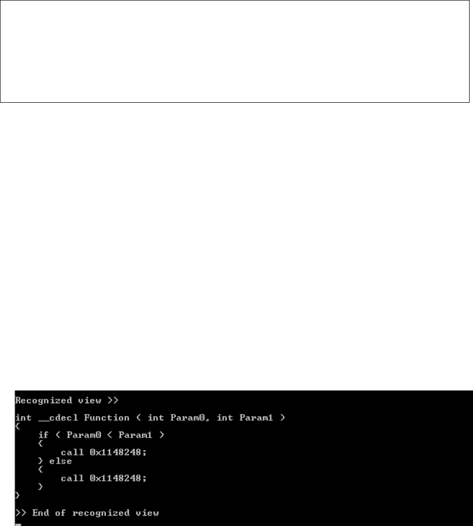
47
Appendix A – Test cases and results
If /else Statements
Original Code
void __cdecl Test2a ( int a, int b )
{
if ( a < b )
printf ( "a < b\n" );
else
printf ( "a >= b\n" );
}
Assembly Code
01141250 push ebp
01141251 mov ebp,esp
01141253 sub esp,40h
01141256 push ebx
01141257 push esi
01141258 push edi
01141259 mov eax,dword ptr [ebp+8]
0114125C cmp eax,dword ptr [ebp+0Ch]
0114125F jge 01141271
01141261 push 1145720h
01141266 call dword ptr ds:[1148248h]
0114126C add esp,4
0114126F jmp 0114127F
01141271 push 1145728h
01141276 call dword ptr ds:[1148248h]
0114127C add esp,4
0114127F pop edi
01141280 pop esi
01141281 pop ebx
01141282 mov esp,ebp
01141284 pop ebp
01141285 ret
Decompiled Output
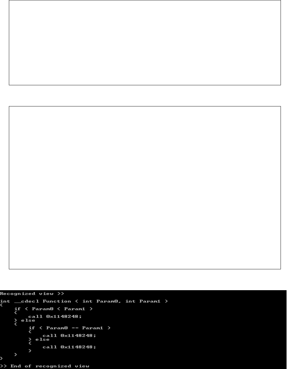
48
Nested if /else statements
Original Code
void __cdecl Test3a ( int a, int b )
{
if ( a < b )
printf ( "a < b\n" );
else
if ( a == b )
printf ( "a = b\n" );
else
printf ( "a > b\n" );
}
Assembly Code
01141340 push ebp
01141341 mov ebp,esp
01141343 sub esp,40h
01141346 push ebx
01141347 push esi
01141348 push edi
01141349 mov eax,dword ptr [ebp+8]
0114134C cmp eax,dword ptr [ebp+0Ch]
0114134F jge 01141361
01141351 push 1145720h
01141356 call dword ptr ds:[1148248h]
0114135C add esp,4
0114135F jmp 01141387
01141361 mov eax,dword ptr [ebp+8]
01141364 cmp eax,dword ptr [ebp+0Ch]
01141367 jne 01141379
01141369 push 114573Ch
0114136E call dword ptr ds:[1148248h]
01141374 add esp,4
01141377 jmp 01141387
01141379 push 1145734h
0114137E call dword ptr ds:[1148248h]
01141384 add esp,4
01141387 pop edi
01141388 pop esi
01141389 pop ebx
0114138A mov esp,ebp
0114138C pop ebp
0114138D ret
Decompiled Output
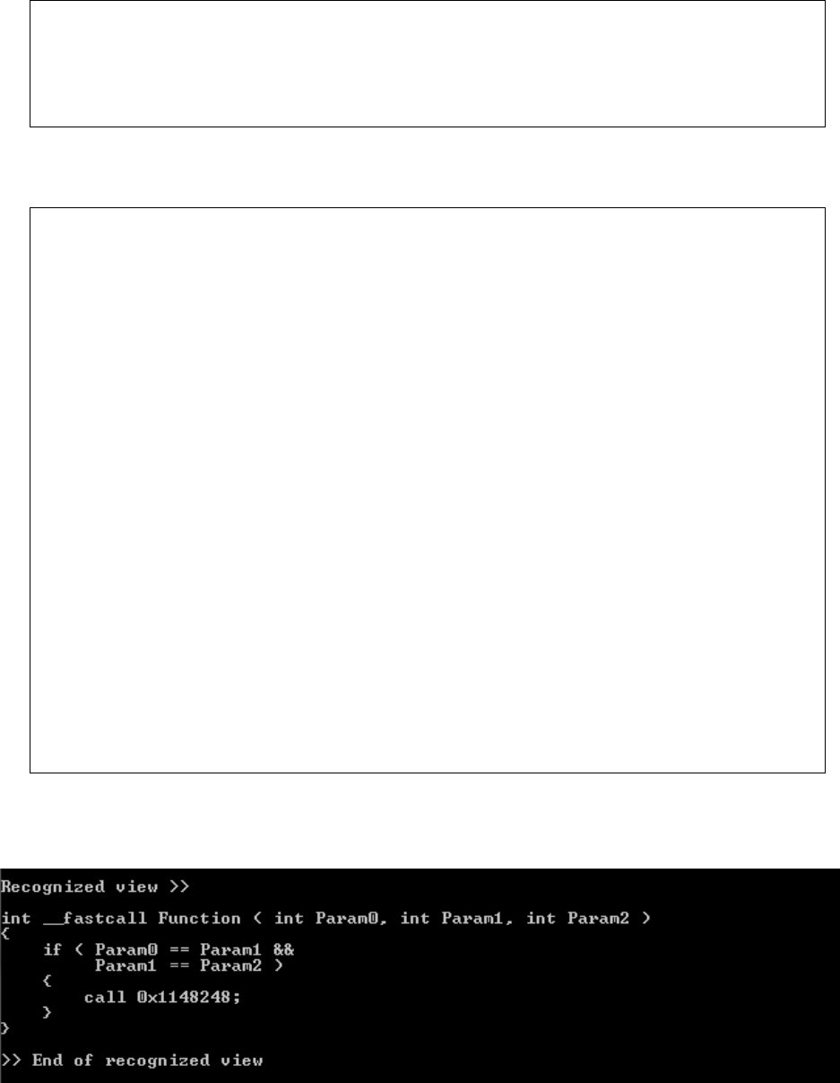
49
Complex if /else statements
Original Code
void __fastcall Test4b ( int a, int b, int c )
{
if ( a == b && b == c )
printf ( "a = b = c\n" );
}
Assembly Code
011414D0 push ebp
011414D1 mov ebp,esp
011414D3 sub esp,48h
011414D6 push ebx
011414D7 push esi
011414D8 push edi
011414D9 mov dword ptr [ebp-8],edx
011414DC mov dword ptr [ebp-4],ecx
011414DF mov eax,dword ptr [ebp-4]
011414E2 cmp eax,dword ptr [ebp-8]
011414E5 jne 011414FD
011414E7 mov eax,dword ptr [ebp-8]
011414EA cmp eax,dword ptr [ebp+8]
011414ED jne 011414FD
011414EF push 1145744h
011414F4 call dword ptr ds:[1148248h]
011414FA add esp,4
011414FD pop edi
011414FE pop esi
011414FF pop ebx
01141500 mov esp,ebp
01141502 pop ebp
01141503 ret 4
Decompiled Output
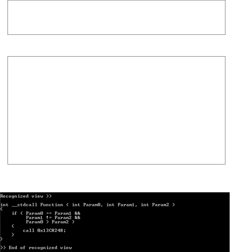
50
Complex if /else statements
Original Code
void __stdcall Test6c ( int a, int b, int c )
{
if ( a == b && b != c && a > c )
printf ( "a = b and b != c and a > c\n" );
}
Assembly Code
013C1720 push ebp
013C1721 mov ebp,esp
013C1723 sub esp,40h
013C1726 push ebx
013C1727 push esi
013C1728 push edi
013C1729 mov eax,dword ptr [ebp+8]
013C172C cmp eax,dword ptr [ebp+0Ch]
013C172F jne 013C174F
013C1731 mov eax,dword ptr [ebp+0Ch]
013C1734 cmp eax,dword ptr [ebp+10h]
013C1737 je 013C174F
013C1739 mov eax,dword ptr [ebp+8]
013C173C cmp eax,dword ptr [ebp+10h]
013C173F jle 013C174F
013C1741 push 13C5768h
013C1746 call dword ptr ds:[13C8248h]
013C174C add esp,4
013C174F pop edi
013C1750 pop esi
013C1751 pop ebx
013C1752 mov esp,ebp
013C1754 pop ebp
013C1755 ret 0Ch
Decompiled Output

51
Complex nested if/else ladder
Original Code
void __cdecl Test7a ( int a, int b, int c )
{
if ( a < b )
{
if ( b < c )
printf ( "a < b and b < c\n" );
else if ( b == c )
printf ( "a < b and b = c\n" );
else
printf ( "a < b and b > c\n" );
} else
if ( a == b )
{
if ( b < c )
printf ( "a = b and b < c\n" );
else if ( b == c )
printf ( "a = b and b = c\n" );
else
printf ( "a = b and b > c\n" );
} else
{
if ( b < c )
printf ( "a > b and b < c\n" );
else if ( b == c )
printf ( "a > b and b = c\n" );
else
printf ( "a > b and b > c\n" );
}
}

52
Assembly Code
01141720 push ebp
01141721 mov ebp,esp
01141723 sub esp,40h
01141726 push ebx
01141727 push esi
01141728 push edi
01141729 mov eax,dword ptr [ebp+8]
0114172C cmp eax,dword ptr [ebp+0Ch]
0114172F jge 01141774
01141731 mov eax,dword ptr [ebp+0Ch]
01141734 cmp eax,dword ptr [ebp+10h]
01141737 jge 01141749
0114173E call dword ptr ds:[1148248h]
01141744 add esp,4
01141747 jmp 0114176F
01141749 mov eax,dword ptr [ebp+0Ch]
0114174C cmp eax,dword ptr [ebp+10h]
0114174F jne 01141761
01141751 push 1145818h
01141756 call dword ptr ds:[1148248h]
0114175C add esp,4
0114175F jmp 0114176F
01141761 push 1145804h
01141766 call dword ptr ds:[1148248h]
0114176C add esp,4
01141774 mov eax,dword ptr [ebp+8]
01141777 cmp eax,dword ptr [ebp+0Ch]
0114177A jne 011417BC
0114177C mov eax,dword ptr [ebp+0Ch]
0114177F cmp eax,dword ptr [ebp+10h]
01141782 jge 01141794
01141784 push 11457F0h
01141789 call dword ptr ds:[1148248h]
0114178F add esp,4
01141792 jmp 011417BA
01141794 mov eax,dword ptr [ebp+0Ch]
01141797 cmp eax,dword ptr [ebp+10h]
0114179A jne 011417AC
0114179C push 11457DCh
011417A1 call dword ptr ds:[1148248h]
011417A7 add esp,4
011417AA jmp 011417BA
011417AC push 11457C8h
011417B7 add esp,4
011417BA jmp 011417FA
011417BC mov eax,dword ptr [ebp+0Ch]
011417BF cmp eax,dword ptr [ebp+10h]
011417C2 jge 011417D4
011417C4 push 11457B4h
011417CF add esp,4
011417D2 jmp 011417FA
011417D4 mov eax,dword ptr [ebp+0Ch]
011417D7 cmp eax,dword ptr [ebp+10h]
011417DA jne 011417EC
011417DC push 11457A0h
011417E1 call dword ptr ds:[1148248h]
011417E7 add esp,4
011417EA jmp 011417FA
011417EC push 114578Ch
011417F1 call dword ptr ds:[1148248h]
011417F7 add esp,4
011417FA pop edi
011417FB pop esi
011417FC pop ebx
011417FD mov esp,ebp
011417FF pop ebp
01141800 ret

53
Decompiled Output

54
Switch case
Original Code
void __stdcall Test9c ( int a )
{
switch ( a )
{
case 0:
printf ( "a = 0\n" );
break;
case 1:
printf ( "a = 1\n" );
break;
case 2:
printf ( "a = 2\n" );
break;
default:
printf ( "a out of range\n" );
break;
}
}
Assembly Code
00BF1E50 push ebp
00BF1E51 mov ebp,esp
00BF1E53 sub esp,44h
00BF1E56 push ebx
00BF1E57 push esi
00BF1E58 push edi
00BF1E59 mov eax,dword ptr [ebp+8]
00BF1E5C mov dword ptr [ebp-44h],eax
00BF1E5F cmp dword ptr [ebp-44h],0
00BF1E63 je 00BF1E73
00BF1E65 cmp dword ptr [ebp-44h],1
00BF1E69 je 00BF1E83
00BF1E6B cmp dword ptr [ebp-44h],2
00BF1E6F je 00BF1E93
00BF1E71 jmp 00BF1EA3
00BF1E73 push 0BF585Ch
00BF1E78 call dword ptr ds:[0BF8248h]
00BF1E7E add esp,4
00BF1E81 jmp 00BF1EB1
00BF1E83 push 0BF5854h
00BF1E88 call dword ptr ds:[0BF8248h]
00BF1E8E add esp,4
00BF1E91 jmp 00BF1EB1
00BF1E93 push 0BF5840h
00BF1E98 call dword ptr ds:[0BF8248h]
00BF1E9E add esp,4
00BF1EA1 jmp 00BF1EB1
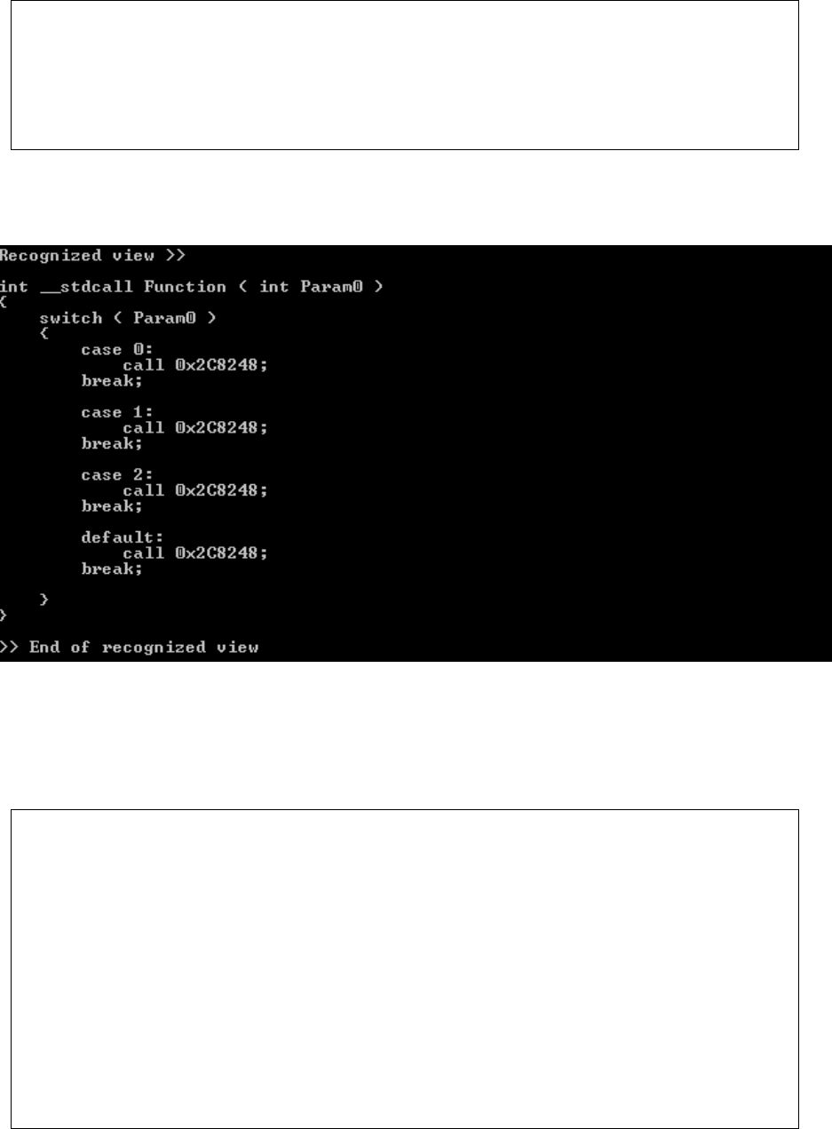
55
00BF1EA3 push 0BF5BA8h
00BF1EA8 call dword ptr ds:[0BF8248h]
00BF1EAE add esp,4
00BF1EB1 pop edi
00BF1EB2 pop esi
00BF1EB3 pop ebx
00BF1EB4 mov esp,ebp
00BF1EB6 pop ebp
00BF1EB7 ret 4
Decompiled Output
For loop with break and continue
Original Code
void __stdcall Test13c ( int a, int b, int c )
{
for ( int i = 0; i < c; i += 3 )
{
if ( i == b )
break;
if ( i == a )
continue;
printf ( "%d\n", i );
}
}
56
Assembly Code
012D1EC0 push ebp
012D1EC1 mov ebp,esp
012D1EC3 sub esp,44h
012D1EC6 push ebx
012D1EC7 push esi
012D1EC8 push edi
012D1EC9 mov dword ptr [ebp-4],0
012D1ED0 jmp 012D1EDB
012D1ED2 mov eax,dword ptr [ebp-4]
012D1ED5 add eax,3
012D1ED8 mov dword ptr [ebp-4],eax
012D1EDB mov eax,dword ptr [ebp-4]
012D1EDE cmp eax,dword ptr [ebp+10h]
012D1EE1 jge 012D1F0B
012D1EE3 mov eax,dword ptr [ebp-4]
012D1EE6 cmp eax,dword ptr [ebp+0Ch]
012D1EE9 jne 012D1EED
012D1EEB jmp 012D1F0B
012D1EED mov eax,dword ptr [ebp-4]
012D1EF0 cmp eax,dword ptr [ebp+8]
012D1EF3 jne 012D1EF7
012D1EF5 jmp 012D1ED2
012D1EF7 mov eax,dword ptr [ebp-4]
012D1EFA push eax
012D1EFB push 12D586Ch
012D1F00 call dword ptr ds:[12D8248h]
012D1F06 add esp,8
012D1F09 jmp 012D1ED2
012D1F0B pop edi
012D1F0C pop esi
012D1F0D pop ebx
012D1F0E mov esp,ebp
012D1F10 pop ebp
012D1F11 ret 0Ch
Decompiled Output

57
Floating point math operations
Original Code
void Test15 ( float a, float b )
{
float c;
c = a + b;
printf ( "%f\n", c );
c = a - b;
printf ( "%f\n", c );
c = a * b;
printf ( "%f\n", c );
c = a / b;
printf ( "%f\n", c );
}
Assembly Code
012D2490 push ebp
012D2491 mov ebp,esp
012D2493 sub esp,44h
012D2496 push ebx
012D2497 push esi
012D2498 push edi
012D2499 fld dword ptr [ebp+8]
012D249C fadd dword ptr [ebp+0Ch]
012D249F fstp dword ptr [ebp-4]
012D24A2 fld dword ptr [ebp-4]
012D24A5 sub esp,8
012D24A8 fstp qword ptr [esp]
012D24AB push 12D5730h
012D24B0 call dword ptr ds:[12D8248h]
012D24B6 add esp,0Ch
012D24B9 fld dword ptr [ebp+8]
012D24BC fsub dword ptr [ebp+0Ch]
012D24BF fstp dword ptr [ebp-4]
012D24C2 fld dword ptr [ebp-4]
012D24C5 sub esp,8
012D24C8 fstp qword ptr [esp]
012D24CB push 12D5730h
012D24D0 call dword ptr ds:[12D8248h]
012D24D6 add esp,0Ch
012D24D9 fld dword ptr [ebp+8]
012D24DC fmul dword ptr [ebp+0Ch]
012D24DF fstp dword ptr [ebp-4]
012D24E2 fld dword ptr [ebp-4]
012D24E5 sub esp,8
012D24E8 fstp qword ptr [esp]
012D24EB push 12D5730h
012D24F0 call dword ptr ds:[12D8248h]
012D24F6 add esp,0Ch
012D24F9 fld dword ptr [ebp+8]
012D24FC fdiv dword ptr [ebp+0Ch]
012D24FF fstp dword ptr [ebp-4]
012D2502 fld dword ptr [ebp-4]
012D2505 sub esp,8
012D2508 fstp qword ptr [esp]
58
012D250B push 12D5730h
012D2510 call dword ptr ds:[12D8248h]
012D2516 add esp,0Ch
012D2519 pop edi
012D251A pop esi
012D251B pop ebx
012D251C mov esp,ebp
012D251E pop ebp
012D251F ret
Decompiled Output

59
References
1. M. Emmerich (2007). Static Single Assignment for Decompilation.
2. P. Enzo (2009). ASM to C Translation table.
3. Decompiler topics (2011) retrieved from:
http://www.compwisdom.com/topics/Decompiler
4. Decompilation Wiki (2011) retrieved from:
http://program-transformation.org/Transform/DeCompilation
5. The dcc compiler (2011) retrieved from:
http://www.itee.uq.edu.au/~cristina/dcc.html
6. REC compiler (2011) retrieved from:
http://www.backerstreet.com/rec/rec.htm
7. Paul Carter (2004). PC assembly language.
8. Intel assets (2011). Intel 64 and IA32 architecture. Volume 2 (2A & 2B): Instruction Set
Reference, A-Z.
9. E. Chikofsky and J. Cross (1990). Reverse engineering and design recovery.
10. C. Mills, S. Ahalt, and J. Fowler (1991). Compiled instruction set simulation. Software _
Practice and Experience.
11. G. Morrisett, D. Walker, K. Crary, and N. Glew (1998). From System F to typed
assembly language.
12. Matt Pietrek (2002). An In-Depth Look into the Win32 Portable Executable File Format.
February 2002 issue of MSDN Magazine.
13. C. Cifuentes. (1994). Reverse Compilation Techniques.
14. G. Balakrishnan, T. Reps, D. Melski, and T. Teitelbaum (2005). WYSINWYX:What You
See Is Not What You eXecute.
15. R. Horspool and N. Marovac (1979). An approach to the problem of detranslation of
computer programs.
16. D. Eriksson (2002). Desquirr web page.
17. A. Mycroft (1999). Type-based decompilation.
18. Andromeda decompiler (2004). Andromeda decompiler web page.
19. I. Guilfanov (2007). Decompilation gets real.
60
20. Austin Code Works (1990), Exec-2 Decompiler
21. Balmas, Francoise (2001).
Displaying dependence graphs: a hierarchical approach.
22. M. T. Goodrich and R. Tamassia (1998). Data Structures and Algorithms.
23. Scott, M. Lee (2005). Programming Language Pragmatics.
24. G. Caprino (2003). REC - Reverse Engineering Compiler.
25. S. Kumar (2001). Disc.
26. J. Miecznikowski and L. Hendren (2002). Decompiling Java bytecode: Problems,
traps and pitfalls.
27. J. Hoenicke (2000). Java Optimize and Decompile Environment.
28. P. Kouznetsov (1999). JAD - the fast JAva Decompiler.
29. K. Kumar (2001). JReversePro - Java decompiler.
30. V. Schneider and G. Winiger (1974). Translation grammars for compilation and
Decompilation.
31. J. Reuter (1988). Public domain software.
32. Muchnick, Steven (1997). Advanced Compiler Design and Implementation.
