
1
2
EFIS App for iPad
Operation Manual
Table of Contents
1. Introduction to EFIS App for iPad ...................................... 3
2. Configuring the Device and Host ....................................... 4
I. Configuring the iPad
II. Configuring the Host Computer
A. Updating X-Plane as Needed
B. Allowing X-Plane through Your Firewall
C. Configuring an Up-to-Date Copy of X-Plane
D. Troubleshooting Network Issues
3. Using the Application ......................................................... 8
I. The X-Vision Display
A. The PREFL Tab
B. The PLAN Tab
C. The PFD-S Tab
i. The Artificial Horizon
ii. The Directional Gyro and Other
Indicators
iii. The Autopilot Tab
iv. The Navigation Tab
v. The Communication Tab
vi. The Transponder/Barometer Tab
D. The MAP Tab
i. Airports in the Map Tab
ii. NAVAIDs in the Map Tab
iii. Miscellaneous Navigation Information
E. The SYSTEM Tab
F. The SETUP Tab
G. The DIAG Tab
II. The Standby Mechanical Gauges
4. Tech Support ....................................................................... 16
3
1. Introduction to EFIS App for iPad
EFIS App for iPad is the easiest, most cost-effective way to
build a very high-quality home flight simulator. By transforming
a regular iPad into an electronic flight instrument system
(EFIS) display, the application provides a means of building a
very convincing glass cockpit in your home with minimal effort.
Here’s how it works:
Using EFIS App, an iPad (or two, or three, or four!) can be
configured as one of a number of different EFIS displays. In
the original release of the application, users can choose
between a synthetic vision display, a wireframe view of the
ground, and a steam gauge panel. Using the included PFD
and MFD, a staggeringly powerful amount of information and
control is available. This ranges from flight planning tools, to
communications and navigation controls, to autopilots, to
moving maps, to systems status displays.
EFIS App integrates seamlessly into a copy of X-Plane
running on your Mac, Windows, or Linux machine—setup
consists of nothing more than telling your desktop/laptop copy
of X-Plane where to find the EFIS App iPad.
To really put the application to use, you can attach your
iPad(s) to an instrument panel you build from plywood in your
home, mount a “normal”-quality projector on your ceiling, and
connect your Mac or PC to the projector. You would then have
a simulator with spectacular visuals projected in front of you,
cool EFIS instruments on the panel, and the best flight model
in the industry—a simulator that would rival professional ones
costing hundreds of thousands of dollars.
EFIS App for iPad will spark a revolution in homebuilt, no-
hassle cockpits. What’s stopping you from being a part of it?
4
2. Configuring the Device and Host
I. Configuring the iPad
Each iPad that will run EFIS App must be connected to the
same network as the host computer (the desktop/laptop
running X-Plane), with no intervening subnetworks.
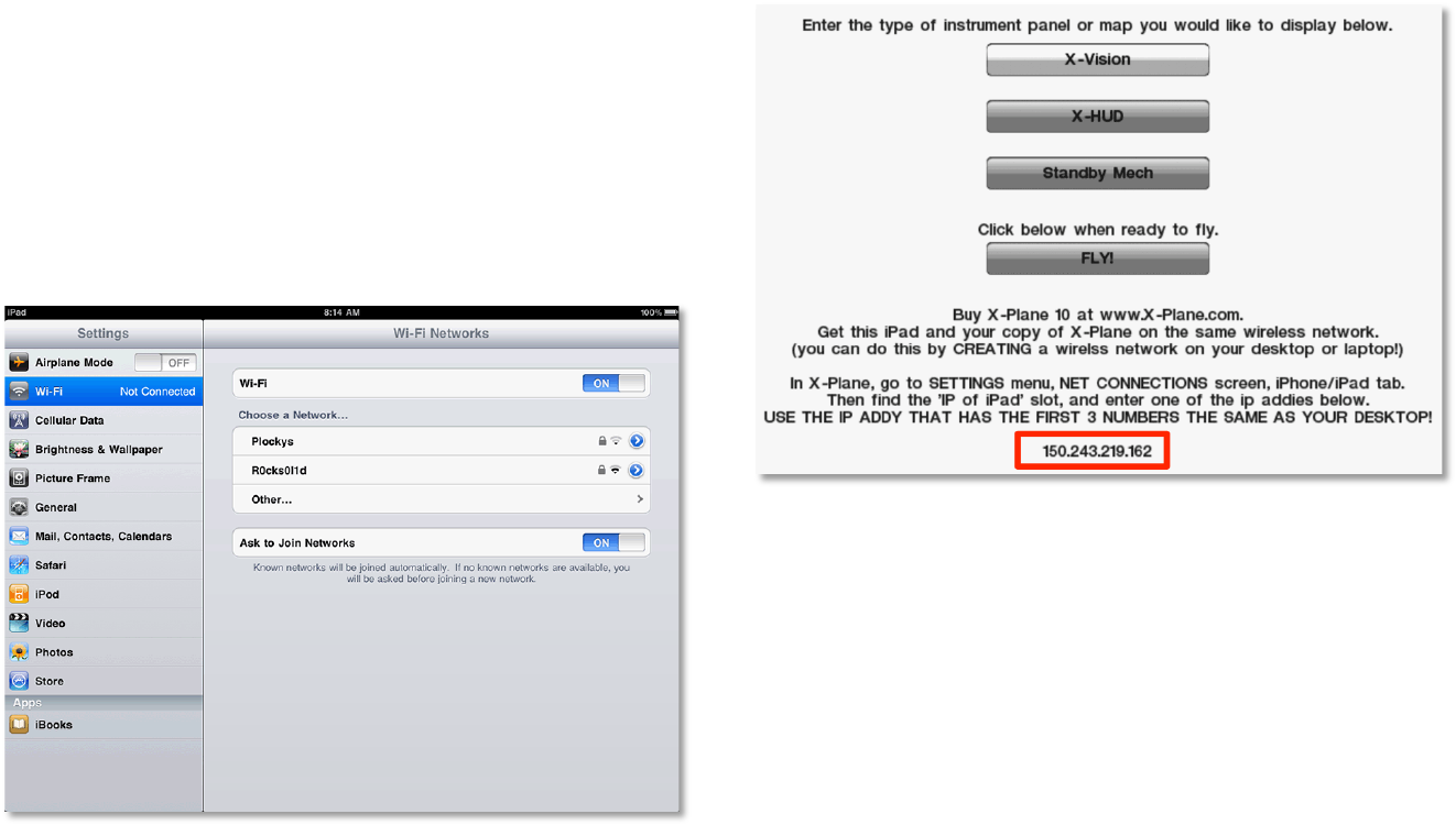
To connect the iPad to your wireless network, tap the Settings
icon on the device’s home screen. There, tap Wi-Fi and select
your home network from the list (as seen in the following
image).
Once connected, launch EFIS App from the iPad’s home
screen. Once the application loads, it will display the iPad’s IP
address near the bottom of the screen. For instance, in the
following screenshot, EFIS App is telling us that the iPad’s IP
address is 150.243.218.185.
Write down the number EFIS App gives you (or just keep your
iPad running), as we will need this address when configuring
the host computer.
II. Configuring the Host Computer
In order to interface with EFIS App for iPad, the X-Plane
software installed on the host computer must be updated to
version 9.61 or later.
A. Updating X-Plane as Needed
5
To determine if X-Plane needs to be updated and, if required,
perform the update:
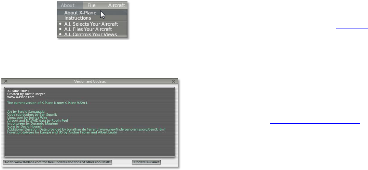
1. Launch the copy of X-Plane on the host computer.
2. Once it opens, move your mouse to the top of the
screen and click About, then click About X-Plane (as seen
in the following image).
3. Check the version number listed at the top of the
window that appears. If it reads anything prior to “X-Plane
9.61RC1,” the software needs to be updated.
4. If necessary, click the Update X-Plane button. This will
cause X-Plane to automatically download the latest version
of the updater program and launch it.
5. When the updater window appears, it will already have
the correct copy of X-Plane selected (since it was launched
from within the simulator). Click Continue.
6. Assuming there is enough disk space to download the
required updates, click Continue to begin the installation.
7. The installation files will be downloaded and installed,
after which the host system is ready to go.
Alternatively, you can use the updater downloaded from our
website. For instructions on doing so, please see this section
in the X-Plane Desktop manual. In particular, note that the
Check for new betas box must be checked when searching
for updates.
B. Allowing X-Plane through Your Firewall
In order for your computer to “see” EFIS App running on your
iPad, you must allow X-Plane to communicate through your
firewall. If your computer is not running a firewall, you can skip
this step entirely.
To allow a program through the firewall in Windows XP, follow
Microsoft’s instructions in Knowledge Base Article 842242
.
To do this in Windows Vista and Windows 7,
1. Open Windows Firewall by clicking the Start button,
clicking Control Panel, clicking Security, and then
clicking Windows Firewall.
2. In the left pane, click Allow a program through
Windows Firewall. If you are prompted for
confirmation, click Allow.

6
3. (Windows 7 only:) Click Change settings, then click
Allow if asked for confirmation.
4. Select the check box next to X-Plane, and then click
OK.
To allow X-Plane through the firewall in Mac OS,
1. Open System Preferences from the Apple menu.
2. Click Security (called Security & Privacy in OSX Lion).
3. Click the Firewall tab.
4. Unlock the pane by clicking the lock in the lower-left
corner and enter the administrator username and
password.
5. Click Advanced to customize the firewall configuration.
6. Click the + (plus) button, then select your copy of X-
Plane.app. This is found in the X-Plane 9 or X-Plane 10
installation directory, which is located by default on
your desktop. With X-Plane selected, click Add.
C. Configuring an Up-to-Date Copy of X-Plane
With the mobile device on the same network and desktop
software updated to version 9.61 or later, it’s time to configure
the desktop software to interface with the device.
Before we begin, make sure that the iPad is on and running
EFIS App. This will ensure that it is transmitting over the
network so that the desktop copy of X-Plane can interface with
it.
In the desktop copy of X-Plane, move the mouse to the top of
the screen, making the menu bar appear. Click Settings, then
select Net Connections, as seen in the following image.
In the window that appears, click the iPhone/iPad tab (labeled
Advanced in X-Plane 9) at the top of the window.
Found in the lower half of this window is a box labeled IP of
iPad running EFIS App. Check this box and enter the IP
address that we found in Section I of this chapter, Configuring
the iPad.
In the image above, the iPad being used happened to have an
IP address of 150.243.218.185. A typical home network may
use IP addresses like 192.168.x.x.
At this point, the mobile device and the desktop copy of X-
Plane are ready to work together. After entering the correct IP
address, EFIS App on the iPad will confirm that is it getting
data from the desktop/laptop copy of X-Plane—the yellow text
at the bottom of the screen will read “Getting data from X-
Plane now! We are ready to fly!”
D. Troubleshooting Network Issues
If you have trouble with networking between X-Plane and EFIS
App for iPad, check the following:
• Ensure that the ports used by X-Plane (ports 49,000
through 49,002) are not being blocked by any firewall.
A firewall may be software running on your computer
(e.g., Windows’ built-in firewall) or a part of your
network hardware (e.g., built into your router).
7
• Ensure that the computer running X-Plane is on the
same subnet as your iPad. Note that it is very common
for corporate networks to split their wired and wireless
networks into different subnets, so it may help to
connect your computer to the wireless network like
your iPad.
Because of the wide variability in network setups, if you have
trouble networking X-Plane and EFIS App together, we
recommend you consult an IT professional.
8
3. Using the Application
Once both EFIS App and X-Plane have been properly
configured, it’s time to fly.
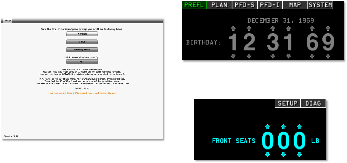
Upon launching EFIS App on the iPad, users are greeted with
the screen seen below.
Here, users can select the view they will use by tapping one of
the four buttons in the top half of the screen. When a button is
colored white (as the X-Vision button is in the image above), it
is selected, and the iPad will go into this mode when the FLY!
button is pressed. Read on for a description of what each
mode does.
I. The X-Vision Display
X-Vision is the primary flight display (PFD) included with EFIS
App. It has six main tabs, found in the top left of the screen,
seen in the image below.
In addition to these, it has two auxiliary tabs for setup and
diagnostics, found in the top right of the screen, seen in the
following image.
To return to the main menu, go to the DIAG tap in the top right
of the screen and tap the MAIN MENU button found at the
bottom of the window.
9
A. The PREFL Tab
The PREFL tab contains pre-flight records as well as weight
and balance tools. To change a value of a field, tap the arrow
above or below a digit to increase or decrease it, respectively.
The fields on the left side of the screen here set the pilot’s date
of birth, date of last biennial flight review (BFR), and dates for
insurance, medical review, and annual flight review. The fields
on the right side of the screen set the center of gravity by
means of the weight in the front seats, rear seats, baggage
compartment, and fuel tanks.
Note that the corners of the center of gravity envelope may be
specified by selecting the SETUP tab from the top of the
screen, then clicking the W-B ENV (that is, weight and balance
envelope) button from the bottom of the screen.
B. The PLAN Tab
The PLAN tab is used for flight planning. Tap the D-> button to
add a destination. Use the keyboard that appears below to
type the destination or waypoint identifier. Use the ADD button
to add another destination, and the INSERT button to insert a
waypoint between two destinations. Finally, use the DELETE
button to remove a waypoint between two destinations.
Directly to the right of each point in the flight plan is the
magnetic course heading, the distance from the previous
waypoint (or the current location, in the case of the first
waypoint on the list), and the total trip distance to that
waypoint.
In the bottom of the screen, EFIS App will “score” the
efficiency of the whole flight in terms of fuel economy (selected
using the ECO button), speed (selected using the SPEED
button), or both (using the BOTH button) for a number of
different altitudes and engine power percentages, estimating
the fuel burn and time for each scenario. The scenario with the
highest score is the most efficient for the criteria selected.
C. The PFD-S Tab
The PFD-S tab is one of the primary flight displays included in
EFIS App. This tab uses a synthetic vision display.
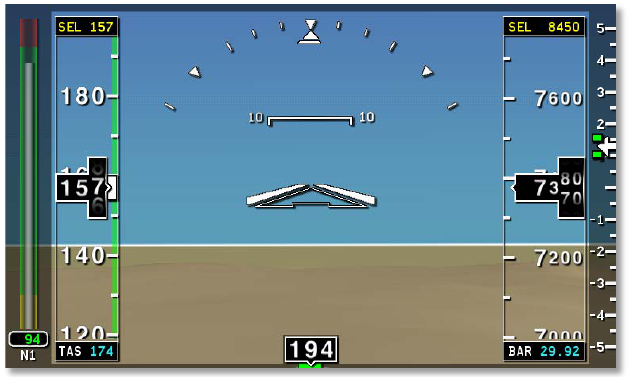
i. The Artificial Horizon
Most prominent in the top half of the screen is the synthetic
vision display, as seen in the following image.
On the far right is the engine’s power output, labeled N1,
which is represented as a percentage of maximum. To the
right of this is the airspeed indicator (reading 157 knots in the
image above). Below the airspeed indicator is the true
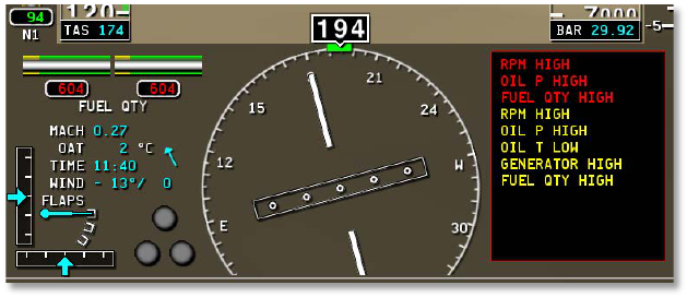
10
airspeed, labeled TAS and reading 174 knots in the image
above.
In the center of the synthetic vision display is the artificial
horizon. The large triangle in the center indicates the aircraft’s
pitch and roll attitude. This is situated atop horizontal bars
indicated degrees of pitch attitude. For instance, in the image
above, the aircraft is pitched less than 10 degrees up.
If the aircraft’s autopilot is engaged, two bars forming a V will
be visible here representing the commanded pitch and roll
from the flight director.
Above the attitude indicator is a simplified view of a turn
coordinator. The center of the three triangles represents a
level wing attitude, and the outer two triangles represent 30
degrees of roll.
To the right of the artificial horizon is the altimeter. In the
image above, the aircraft is about 7375 feet above mean sea
level. To the right of the altimeter is the variometer, displaying
the rate of the aircraft’s climb or descent in hundreds of feet
per minute. For instance, in the image above, the aircraft was
climbing at around 100 feet per minute.
Finally, beneath the altimeter is the barometric pressure of the
outside air.
ii. The Directional Gyro and Other Indicators
Beneath the synthetic vision display is the directional gyro and
other systems information.
On the left side is:
• the aircraft’s fuel quantity (604 pounds in each fuel tank
in the previous image),
• the aircraft’s speed as a decimal of the speed of sound
(0.27 Mach in the previous image),
• the outside air temperature (2° C in the previous
image),
• the current time (11:40 in the previous image),
• the wind direction and speed (-13° and 0 mph in the
previous image), and
• the amount of flaps set (none, in the previous image).
Beneath the systems information and to the left of it are two
black bars with light blue arrows, one bar horizontal and one
vertical. The vertical bar is a glideslope indicator and the
horizontal bar a localizer indicator. Both are used in navigating
runway approaches.
To the right of the LOC indicator are three round dots,
indicating landing gear status—the top dot corresponds to the
front landing gear, the bottom two to the left and right gears.
When the dots are lit green, the gear is down, and when they
are gray, the gear is up. When the dots are lit red, the gear is
being toggled.
11
In the center is a directional gyro, indicating which direction the
aircraft is pointing (in the previous image, 194° from north, or
nearly south).
On the right is a box for operational warnings—for instance, in
the previous image, the aircraft’s engine RPM, oil pressure,
and fuel quantity are all high.
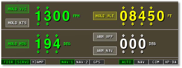
iii. The Autopilot Tab
With the AUTO tab selected in the bottom right of the screen,
as in the following image, controls for the autopilot will fill the
bottom third of the screen.
Before the autopilot can be used, it must be turned on.
Tapping the FDIR button in the bottom right of the screen
(seen in the previous image) will turn on the flight director only.
In this case, the autopilot will not physically move the airplane
controls, but will rather move little target wings on your
synthetic vision display that you can try to mimic as you fly. At
that point, the flight director is following whatever autopilot
modes are selected, and you, in turn, are following the flight
director as you fly the plane. If you also tap the SERVO button
(found just to the right of the FDIR button), then the autopilot
servos will actually fly the airplane according to the autopilot
mode you have selected.
Note that the autopilot will receive input from whichever
navigation source is selected in the bottom center of the
screen, whether the NAV1 radio, NAV2 radio, or GPS.
Tapping the HOLD VVI button will cause the aircraft to hold
the specified vertical rate of ascent or descent (in feet per
minute) by pitching the aircraft’s nose up or down, leaving the
throttle constant.
Tapping the HOLD KTS button will cause the autopilot to
maintain the specified airspeed, in knots, by pitching the nose
up or down, leaving the throttle constant. This is identical to
the SPD button in other autopilot systems.
Tapping the HOLD HDG button will cause the autopilot to
bank the aircraft left or right to maintain the specified heading,
in degrees.
Tapping the HOLD ALT button will cause the autopilot to hold
either the current or pre-selected altitude by pitching the nose
up or down.
The ARM APP and ARM NAV buttons are used to arm the
autopilot so that it automatically captures and flies a given
command. It can be set to capture and fly either an approach
or a NAV source, such as a VOR radial (in which case it would
be following the displacement of an HSI needle) or GPS (in
which case it would be following an electronic CDI and turning
to track a specified heading).
iv. The Navigation Tab
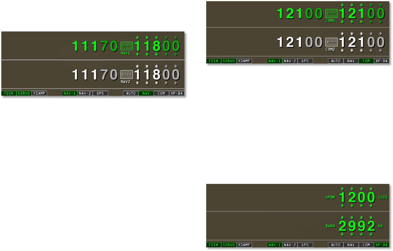
12
With the NAV tab selected in the bottom right of the screen (as
in the following image), two sets of numbers appear. These
are the NAV1 and NAV2 frequencies.
When a radio is selected as the navigation source using one of
the three buttons in the bottom center of the screen, its
frequency will be lit in green. For instance, in the previous
image, the NAV1 radio was selected, so the NAV1 frequency
was green. Note that neither of these frequencies will be lit
when navigating using GPS data (which is controlled using the
PLAN tab at the top of the screen).
The values on the right (one for NAV1 and one for NAV2) are
the standby frequencies. Tuning these will not affect
navigation until the <--- button is pressed, at which point the
active and standby frequency for that radio will switch.
v. The Communication Tab
With the COM tab selected in the bottom right of the screen,
as in the following image, the communications radios can be
tuned just like the navigation radios (see the previous sub-
section).
vi. The Transponder/Barometer Tab
With the XP-BA tab selected in the bottom right of the screen,
the transponder code and barometer setting can be modified
using standard arrows above and below each digit.
In the real world, the ground-level barometric pressure setting,
labeled BARO here, must be modified regularly by the pilot in
order to calibrate the altimeter, which gives a reading based
on the difference between the air pressure around the aircraft
and the pressure on the ground. Note that standard pressure
is 29.92 inches mercury, represented here at 2992.
D. The MAP Tab
13
The MAP tab displays a moving map of the area around the
aircraft. Touch two fingers to the screen and “pinch” them
together to zoom out, or slide them apart to zoom in.
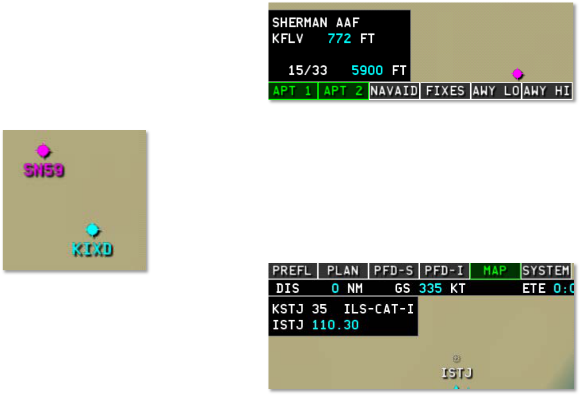
i. Airports in the Map Tab
Airports on the moving map are designated as either light
purple or light blue dots with crosses through them (as seen in
the following image). Beneath this dot is the airport’s ICAO-
designated identifier.
Airports colored light blue can be toggled on or off using the
APT 1 button in the bottom left of the screen, and airports
colored light purple can be toggled on or off using the APT 2
button.
Touching the dot representing an airport in the map display will
display its name, identifier, elevation, runway(s), and runway
length(s). For instance, in the following image, the KFLV
identifier was tapped in the map display. This is the identifier
for Sherman Army Airfield, whose elevation is 772 feet above
mean sea level, and whose runway 15/33 is 5900 feet long.
ii. NAVAIDs in the Map Tab
NAVAIDs work in a similar way to airports. They are shown in
white, with a tight group of dots representing the transmitter.
Tapping on this transmitter will display the NAVAID’s data in
the top left of the screen. For instance, in the following image,
an ILS transmitter was tapped, so EFIS App displays its name
(KSTJ), its associated runway (35), its type (Category I ILS),
its identifier (ISTJ), and its frequency (110.30 MHz).

14
In the following image, an NDB was selected in the map, so
EFIS App displays its name (Amazon), its type (NDB), its
identifier (AZN), and its frequency (2.33 MHz, or 233 kHz).
A localizer was selected in the following image, so as with the
ILS, EFIS App displays its name (KHHR), its associated
runway (25), its type (LOC), its identifier (IHHR), and its
frequency (109.10 MHz).
The fourth and final type of NAVAID shown in the maps is a
VORTAC transmitter. In the following image, the STJ
VORTAC was touched in the map, so EFIS App displays its
name (St. Joseph), its type (VORTAC), its identifier (STJ), and
its frequency (115.50 MHz).
iii. Miscellaneous Navigation Information
At the top of the Map display is an information bar for flight
planning, as seen in the following image.
If the Plan tab has been used to set a destination, the bar will
display, in order from left to right:
• the distance to the destination, in nautical miles,
• the aircraft’s ground speed, in knots,
• the estimated time en route (that is, the time remaining
in the trip at the present velocity), in hours:minutes,
• the vertical speed required, in feet per minute, and
• the fuel reserve, in hours:minutes.
For instance, in the previous image, the aircraft was 27 NM
from its destination, moving at 99 kts, with an ETE of 16
15
minutes. It had a VSR of 29 FPM and a fuel reserve of -16
minutes.
If the Plan tab has not been used to set a destination, only the
ground speed will be displayed here.
E. The SYSTEM Tab
The SYSTEM tab displays gauges for various systems in the
aircraft. These include oil temperature, oil pressure, fuel flow,
engine torque, engine RPM, and fuel quantity, among other
things.
F. The SETUP Tab
The SETUP tab is used to specify various operational
constants. This includes the pilot’s viewpoint, critical speeds in
the aircraft’s operation, weight and balance details, fuel
capacity, systems information constants, and the aircraft’s
performance information. Use the tabs at the bottom of the
window to view each category.
G. The DIAG Tab
The DIAG tab is useful for diagnosing problems in connecting
to the desktop/laptop copy of X-Plane. It lists, in descending
order:
• the iPad’s IP address,
• the IP address of the copy of X-Plane from which it is
receiving data,
• the type of data being received, and
• the time since the last data packet was received.
Additionally, use the Clean screen for 30 seconds button to
have the application ignore all input in order to clean the
screen.
Finally, to return to the main menu, tap the MAIN MENU
button found at the bottom of this window.
II. The Standby Mechanical Gauges
The Standby Mechanical Gauges view displays four steam
gauge-style instruments. From top to bottom, these are:
• the directional gyro, indicating the aircraft’s heading;
• the airspeed indicator, showing the aircraft’s indicated
airspeed;
• the attitude indicator, showing the aircraft’s pitch and
roll relative to the earth; and
• the altimeter, displaying the aircraft’s altitude in feet
above mean sea level.

16
4. Tech Support
The only technical issue that X-Plane customer support has
yet encountered with the X-Plane Mobile applications is
caused by the hardware exceeding its RAM allocation.
Many users leave their iPod, iPhone, or iPad on for literally
months at a time (as the hardware appears to be off when in
fact it is in standby mode). In some cases, this can cause too
much “garbage” to be stored in the RAM. The X-Plane app is
so demanding on the hardware that it comes within 2% of
crashing every device every time it is launched. This isn’t
normally a problem. However, if the “garbage” isn’t cleaned
out of the RAM periodically by restarting the device, it is
possible that X-Plane will exceed the available RAM, causing
a crash.
To perform a reboot of the device, hold the top power button
down for six seconds, then use your finger to slide the power
switch on the screen to off. Leave the unit off for two to three
minutes before turning it back on.
The issues described above happen very infrequently, and in
all cases are fixable by restarting.
For additional assistance, please e-mail info@x-plane.com
or
call 913-269-0976 (Central Standard Time).
