NEC Large-Screen Displays
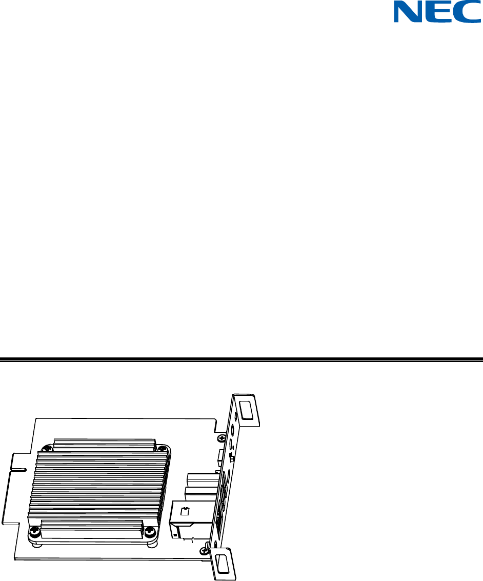
Raspberry Pi Compute Module 4
Setup Guide
Revision: 211020

©2021 Sharp NEC Display Solutions, Ltd. Page 2 of 86
Introduction
This document describes the features, installation, connectivity, and configuration of the Raspberry Pi
Compute Module 4 support in NEC Large-Screen display models. Please see “Requirements” on page 10
for a current list of supported displays and Raspberry Pi hardware.
Notes:
1. The acts of disclosure, duplication, and modification of part or whole contents in this reference
manual without permission are prohibited.
2. The contents of this reference manual are subject to change without notice.
3. Great care has been taken in the preparation of this reference manual; however, should you
notice any questionable points, errors or omissions, please contact us.
Copyright and Trademarks
Copyright © 2021 Sharp NEC Display Solutions, Ltd.
The content of this manual is furnished for informational use only, is subject to change without notice,
and should not be construed as a commitment by Sharp NEC Display Solutions, Ltd. Sharp NEC
Display Solutions, Ltd. assumes no responsibility or liability for any errors or inaccuracies that may
appear in this manual.
Windows® is a registered trademark of Microsoft Corporation.
NEC is a registered trademark of NEC Corporation.
Linux® is the registered trademark of Linus Torvalds in the U.S. and other countries.
Raspberry Pi is a trademark of the Raspberry Pi Foundation.
Apple, Macintosh, Mac, macOS and the Mac logo are trademarks of Apple Inc., registered in the U.S.
and other countries.
Ubuntu is a registered trademark of Canonical Ltd.

©2021 Sharp NEC Display Solutions, Ltd. Page 3 of 86
Contents
Introduction ................................................................................................................................. 2
Contents ...................................................................................................................................... 3
Revision History .......................................................................................................................... 7
Basic Features ............................................................................................................................ 8
GPIO Summary .......................................................................................................................... 10
Interface Board internal connections and jumpers ............................................................... 10
Requirements ............................................................................................................................ 10
Important Cautions ................................................................................................................... 11
About Wireless Connectivity (Wi-Fi and Bluetooth) .............................................................. 11
Operating System Programming Procedure .......................................................................... 12
1 Basic Setup and Configuration Steps ............................................................................... 13
2 Installing the Compute Module and NEC Compute Module Interface Board to the
Display ................................................................................................................................. 14
3 Connections and Internal Operation ................................................................................. 20
3.1 USB device connections to the Compute Module ...................................................................... 20
3.2 USB connections for programming the Compute Module ......................................................... 20
3.3 LAN connections ......................................................................................................................... 22
3.4 Software control via IR Remote .................................................................................................. 24
3.5 GPIO ............................................................................................................................................ 27
4 Preparing and running the tools to program the Compute Module ............................... 28
4.1 Using a Windows PC as a host .................................................................................................... 28
5 Miscellaneous Configuration Items ................................................................................... 33
5.1 Enabling the onboard USB 2.0 controller ................................................................................... 33
5.2 Enabling 4K@60Hz video output ................................................................................................ 33
5.3 Configuring the correct HDMI video level encoding and decoding ............................................ 33
5.4 To disable overscan (if black bars are visible on the sides of the screen) .................................. 35
5.5 To rotate the screen image to portrait orientation .................................................................... 35
5.6 To enable support for the IR Remote receiver using “lirc” ......................................................... 36
5.7 To test support for the IR Receiver by outputting raw data ....................................................... 37
5.8 To enable the serial port (UART) to the display and allowing application access ...................... 37
5.9 Testing internal serial communications to the display using the Python based NEC PD SDK .... 38
©2021 Sharp NEC Display Solutions, Ltd. Page 4 of 86
5.10 Configuring the Compute Module to shutdown using shutdown signal from the display ......... 38
5.11 Reading and setting the display’s internal Real Time Clock (RTC) from the OS ......................... 39
5.12 Using the display’s Watchdog Timer (WDT) ............................................................................... 40
5.13 Controlling the Compute Module power .................................................................................... 41
5.14 Controlling the cooling fan automatically based on the CPU temperature ................................ 41
5.15 Checking and updating the display firmware version ................................................................. 42
5.15.1 Update using the NEC Display Firmware Update Tool for Windows .................................. 42
5.15.2 Update display firmware using a USB storage device ........................................................ 43
6 Related OSD Settings ......................................................................................................... 44
6.1 Slot Compute Module Power Control Power Supply ................................................... 44
6.2 Slot Compute Module Power Control Power Button ................................................... 44
6.3 Slot Compute Module Power Control Reset ................................................................ 45
6.4 Slot Compute Module Power Setting Auto Power Up ................................................. 45
6.5 Slot Compute Module Power Setting Auto Shutdown ................................................. 45
6.6 Slot Compute Module Power Setting Power Supply Off Delay .................................... 46
6.7 Slot Compute Module Power Setting Auto Display Off ................................................ 46
6.8 Slot Compute Module Power Setting Off Warning ...................................................... 47
6.9 Slot Compute Module Advanced Setting Shutdown Signal .......................................... 47
6.10 Slot Compute Module Advanced Setting IR Signal ....................................................... 48
6.11 Slot Compute Module Advanced Setting Monitor Control .......................................... 48
6.12 Slot Compute Module Advanced Setting WDT ............................................................. 48
6.13 Slot Compute Module Advanced Setting WDT Start Up Time ................................. 49
6.14 Slot Compute Module Advanced Setting WDT Period Time ................................... 49
6.15 Slot Slot Power ....................................................................................................................... 50
6.16 Input Advanced CEC CEC ............................................................................................... 50
6.17 Input Advanced CEC Search Device ............................................................................... 51
6.18 Control USB PC Source ...................................................................................................... 51
7 Useful Information and Commands .................................................................................. 54
7.1 To find out the IP address of the Compute Module from a terminal window ........................... 54
7.2 To restart from a terminal window ............................................................................................. 54
7.3 To shutdown from a terminal window ....................................................................................... 54
7.4 To run the Raspberry Pi Config utility from a terminal window ................................................. 54
©2021 Sharp NEC Display Solutions, Ltd. Page 5 of 86
7.5 To change the keyboard layout to US from a terminal window ................................................. 54
7.6 To add and remove packages from Raspberry Pi OS .................................................................. 55
7.7 To update the Raspberry Pi ......................................................................................................... 55
7.8 To install the Python serial module ............................................................................................ 55
7.9 To mount a USB flash drive from the terminal ........................................................................... 55
7.10 To access an SMB (Windows share) drive from the Raspberry Pi OS desktop ........................... 56
7.11 To list connected USB devices .................................................................................................... 56
7.12 To show available disk space ...................................................................................................... 56
7.13 To show internal information about the Raspberry Pi ............................................................... 56
7.14 To download a file to the current directory ................................................................................ 56
7.15 To find a file by name .................................................................................................................. 57
7.16 To edit a protected system configuration file from the Raspberry Pi OS desktop ..................... 57
7.17 To prevent the screen saver from blanking the screen after several minutes ........................... 57
7.18 Monitoring the system processes, CPU usage, and memory ..................................................... 57
7.19 To enable and disable video output from the Compute Module to the display ........................ 57
7.20 To create an image of the Compute Module to backup or clone ............................................... 58
7.21 Debug GPIO lines and overlay assignments ................................................................................ 58
7.22 Assign different MAC address to the network interfaces ........................................................... 58
8 Troubleshooting .................................................................................................................. 59
9 Video CODECs .................................................................................................................... 64
10 Python Based NEC PD SDK ............................................................................................... 65
11 Compute Module Configuration Tool for Raspberry Pi OS ............................................. 67
12 Wireless connectivity installation and configuration ...................................................... 69
12.1 Important cautions ..................................................................................................................... 69
12.2 Parts identification ...................................................................................................................... 70
12.3 Installing the antenna connector to the Compute Module and routing the coax cable ............ 71
12.4 Enabling and disabling Wi-Fi at the hardware level .................................................................... 76
12.5 Selecting the external antenna in software ................................................................................ 76
12.6 Bluetooth functionality ............................................................................................................... 76
12.7 Troubleshooting wireless functionality ....................................................................................... 76
13 External reference information .......................................................................................... 78
14 Frequently Asked Questions ............................................................................................. 80
©2021 Sharp NEC Display Solutions, Ltd. Page 6 of 86
15 Known Issues ...................................................................................................................... 84
16 Support ................................................................................................................................ 85
17 Disclaimer ............................................................................................................................ 86

©2021 Sharp NEC Display Solutions, Ltd. Page 7 of 86
Revision History
Revision
Date
Modified by
Description
210526
May 26, 2021
Will Hollingworth
Initial release
211020
October 20 2021
Will Hollingworth
Add wireless information

©2021 Sharp NEC Display Solutions, Ltd. Page 8 of 86
Basic Features
• Operating System support
o Select from many publicly available OS distributions and images depending on the
application, such as: fully featured and ready to use networked media players, kiosk
interfaces, full desktop based operating systems, and minimal systems.
A custom developed NEC Media Player image is also available.
• Network connectivity
o Gigabit LAN connection on the Raspberry Pi Compute Module Interface Board for direct
high-speed connection to the Compute Module.
o 10/100 LAN switch internal to the display provides network connectivity to both the
display and Raspberry Pi Compute Module using a single network connection. The
display’s LAN control interface and the Compute Module will have their own IP address
and network settings.
o (Multiple LAN port display models
1
) Two of the display’s LAN switch ports are available
externally for daisy-chaining other devices.
- LAN1 port should be used to connect to the network.
- LAN2 output can be used to connect other LAN devices or displays.
o Built-in Wi-Fi on supported models.
• USB connectivity
o Two USB 2.0 Type-A connectors (500mA power) on the Raspberry Pi Compute Module
Interface Board for connecting devices such as keyboards, mice, and other USB
peripherals.
o (Display models with “USB-A” connection
2
) An additional USB 2.0 internal connection to
the display’s built-in USB Type-A port. This port can be switched between the Raspberry
Pi Compute Module, another SDM based device, or an external PC. This can be set to
switch automatically, depending on the currently selected video input, or fixed to a
specific source.
o Direct programming of the Compute Module from an external PC via a USB 2.0 Micro-B
connector on the Raspberry Pi Compute Module Interface Board.
• Internal IR Remote receiver and pass through to the Raspberry Pi Compute Module
o The display's IR Remote can be used to operate software running on the Raspberry Pi
Compute Module, such as a media player, via standard IR Remote Control units. The IR
Remote communicates to the Compute Module via the display's internal remote control
sensor or external KT-RC3 sensor. It will be necessary to configure such software with
the IR codes for the remote control units being used.
o This uses GPIO 18 on the Raspberry Pi.
1
Current display models with multiple LAN ports on the terminal panel: MA431, MA491, MA551, P435, P495, P555
2
Current display models with port labeled “USB-A” on the terminal panel: MA431, MA491, MA551, P435, P495,
P555
©2021 Sharp NEC Display Solutions, Ltd. Page 9 of 86
• CEC support between the display and the Raspberry Pi Compute Module.
o Facilitates the use of the display’s IR Remote buttons to control the basic navigation
functions of compatible software, such as media players.
• Internal serial connection between the display and the Raspberry Pi Compute Module
o Allows full control and monitoring of the display from the Compute Module.
o This uses GPIO 14 & 15 (UART0) on the Raspberry Pi Compute Module.
o A Python based SDK is available from Sharp NEC Display Solutions for easy software
development. See Python Based NEC PD SDK on page 65.
• Real Time Clock support via the display’s internal clock
o The display’s internal Real Time Clock can be read and set via the Compute Module,
using the internal serial connection and the Python based SDK.
o This can be used to set the system time when no network connection is available.
• Shutdown signal support
o The display can signal to the Operating System, running on the Raspberry Pi Compute
Module, that the power is about to turn off so the software and OS can shutdown
gracefully.
o This uses GPIO 23 on the Raspberry Pi Compute Module.
• Full power control
o Power for the Compute Module can be configured to automatically turn on when the
display is turned on from a standby mode, or it can be turned on separately via the
display’s OSD, HTTP interface, or network commands.
o By default, the Compute Module will remain powered on even when the display goes
into standby mode and can be turned off separately via the display’s OSD, HTTP
interface, or network commands.
The display can be configured to turn off the Compute Module power with the display
power.
• Watchdog timer support
o Can be used to reset a locked CPU by automatically restarting the Compute Module. A
restart will occur if no periodic reset signal is received from the Compute Module within
a certain time period.
• Built in touchscreen support
o For display models integrated with an optional 3
rd
party touchscreen, the USB touch
device will appear as a standard USB HID (Human Interface Device) device to the
Compute Module.
• Wi-Fi and Bluetooth support
o See the following section About Wireless Connectivity (Wi-Fi and Bluetooth) on page 11
for information about the wireless connectivity.
• Cooling
o The large heatsink combined with cooling fans integrated within the display simplifies
heat management.

©2021 Sharp NEC Display Solutions, Ltd. Page 10 of 86
o A temperature sensor within the display automatically starts the cooling fans when
needed. Additionally, the Compute Module itself can request the cooling fans run by
driving GPIO 24 to a high state. This is compatible with the Raspberry Pi OS Fan GPIO
control mechanism.
• Status indicator
o LED indicator on the Raspberry Pi Compute Module Interface Board shows the status of
power (red) and activity (orange).
GPIO Summary
• GPIO 14 & 15 (UART0 TX & RX) – internal serial connection to the display for control
• GPIO 18 – (input to Compute Module) demodulated IR receiver from the display
• GPIO 23 – (input to Compute Module) shutdown signal
• GPIO 24 – (output from the Compute Module) cooling fan control
See section 3.5 GPIO on page 27 for more details.
Interface Board internal connections and jumpers
• A jumper header labeled EEPEOM_nWP on the Interface Board can be used to write-protect the
Compute Module’s EEPROM by installing a jumper across the two pins.
• (DS1-IF21CE interface board only.) A jumper header labeled
WF_nDisable on the Interface
Board can be used to disable the Compute Module’s Wi-Fi function by installing a jumper across
the two pins.
Requirements
• Compatible NEC display models
o M431
o M491
o M551
o
M651
o MA431
o MA491
o MA551
o ME431
o ME501
o ME551
o
ME651
o P435
o P495
o P555
• NEC Compute Module 4 Interface Board
o DS1-IF20CE or DS1-IF21CE
• Raspberry Pi Compute Module 4
o Supports all eMMC based variants, including all RAM and wireless configurations.

©2021 Sharp NEC Display Solutions, Ltd. Page 11 of 86
o Note: “Lite” versions of the Compute Module 4 without onboard eMMC Flash memory
are not supported.
• Internet connection
• LAN hub and standard network cables
• Standard USB 2.0 or 3.x cable (USB to USB Micro-B) for programming.
Lengths of up to 10 feet or 2.5 M can be used with high quality USB cables.
• Host PC running either Windows, macOS, or Ubuntu, or a standard Raspberry Pi 1 / 2 / 3 / 4
running Raspberry Pi OS
• USB keyboard and mouse for connecting to the display (recommended)
• Operating system
.img file
• Software configuration tools (see following sections)
Important Cautions
• Always disconnect the display from AC power when inserting or removing the Interface Board
from the display.
• The two sets of connectors on the Compute Module 4 and the Interface Board are very fragile
and are rated at about 30 insertions maximum. Therefore, do not mate and un-mate the two
unnecessarily.
• When mating the Compute Module 4 to the Interface Board pay careful attention to the
orientation of the Compute Module.
• The included heatsink should be attached to the Compute Module after testing and before final
installation to provide cooling for the Compute Module. The included thermal conductive sheet
should always be used between the heatsink and the Compute Module.
• Disconnect the programming USB Micro-B cable from the Interface Board when programing is
complete. Leaving it connected will result in the USB ports and internal 10/100 LAN being
inactive.
About Wireless Connectivity (Wi-Fi and Bluetooth)
• The DS1-IF21CE interface board together with a wireless enabled version of the Compute
Module 4 and external antenna kit can be used for Wi-Fi functionality. At the time of writing,
Bluetooth functionality is disabled pending regulatory approvals. See the relevant sections of
this guide for information on installing and configuring the wireless functions.
• An external USB wireless adapter “dongle” can be used can be used with either the DS1-IF20CE
or DS1-IF21CE Interface Boards to provide wireless functions.

©2021 Sharp NEC Display Solutions, Ltd. Page 12 of 86
Operating System Programming Procedure
If a Compute Module was included with the kit, it may be pre-programmed with the NEC MediaPlayer
image. This can be overwritten as desired.
Standard Compute Modules from Raspberry Pi are not programmed with an Operating System by default.
The OS can be installed after placing the Compute Module in programming boot mode. This allows the
Compute Module to appear as a USB device to another “host” PC or Raspberry Pi. The Operating
System is then programmed, or “installed”, from the host to the Compute Module over USB. After the OS
is programmed successfully, any necessary configuration options can be made, and the Compute Module
can be restarted in normal boot mode.
The “host” can be a PC running Windows® or Linux®, or a standard Raspberry Pi 1, 2, 3, or 4 with
Raspberry Pi OS. If using a Linux based PC or Raspberry Pi as a host, a small utility will need to be
downloaded and compiled on the host.
Important: The Compute Module will typically not display video until it has been programmed with a
compatible Operating System.
©2021 Sharp NEC Display Solutions, Ltd. Page 13 of 86
1 Basic Setup and Configuration Steps
The following list shows the basic steps that will be performed:
1. Physically install the Raspberry Pi Compute Module 4 into the NEC Compute Module Interface
Board and install into the display. See section 2 on page 14 for details.
2. Connect the host PC to the Interface Board in the display via the USB Micro-B connector for
programming the module. Connect other USB devices, such as a keyboard and mouse, for
configuration and use. See section 3 on page 20 for details.
Note: If the Compute Module is to be programmed with a new OS, follow these steps after
connecting any USB devices:
1. Select and download the OS to install on the Compute Module as well as any other software
tools. See section 4 on page 28 for details.
2. Prepare and run the tools to make the Compute Module appear as a Mass Storage device on the
host system so the OS can be imaged.
3. Image the OS from the host system to the Compute Module.
4. Configure any boot options by editing the config.txt and cmdline.txt files on the boot partition.
See section 5 on page 33 for details.
5. Restart the Compute Module.
6. Configure other boot and runtime options. See section 7 on page 54 for details.
7. Check for any system and firmware updates. See section 7.7 on page 55.
©2021 Sharp NEC Display Solutions, Ltd. Page 14 of 86
2 Installing the Compute Module and NEC Compute
Module Interface Board to the Display
1. Disconnect AC power from the display.
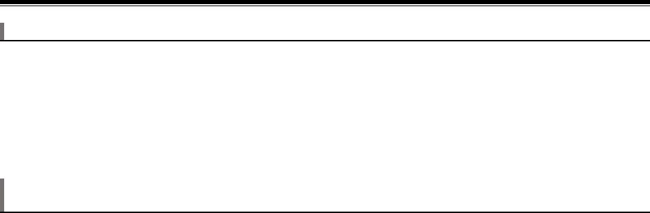
2. Install a Compute Module into the connector of the Interface Board. Check that the Compute
Module is oriented correctly before fully inserting it into the connector. Carefully align the two
rows of connectors and press together evenly to snap together.
Caution: Take static precaution measures when handling the boards.
Figure 2-1: Install the Raspberry Pi Compute Module
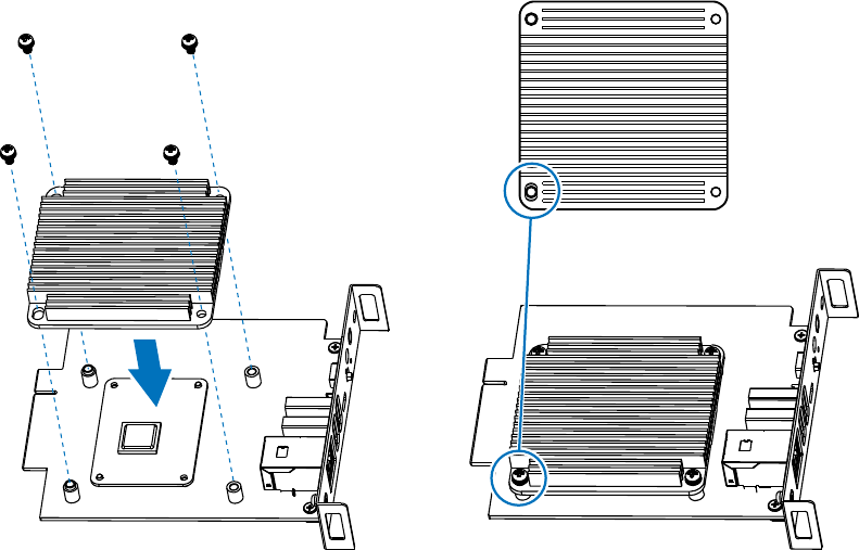
3. Confirm the Compute Module is correctly mated by looking at each corner of the Interface
Board. Metal posts should protrude from two corners, diagonal from each other.
Figure 2-2: Confirm correct installation by alignment of metal posts
Note: to ensure proper orientation for Compute Module installation, the Interface Board has
two diagonal posts that protrude through two corners of the Compute Module. The opposite
two corners of the Compute Module rest on two screw hole pillars. It is not necessary to secure
©2021 Sharp NEC Display Solutions, Ltd. Page 15 of 86
the Compute Module using screws since the heatsink will be used to hold it in place. However, if
desired two 2mm or 2.5mm M2 screws [not supplied] can be used.
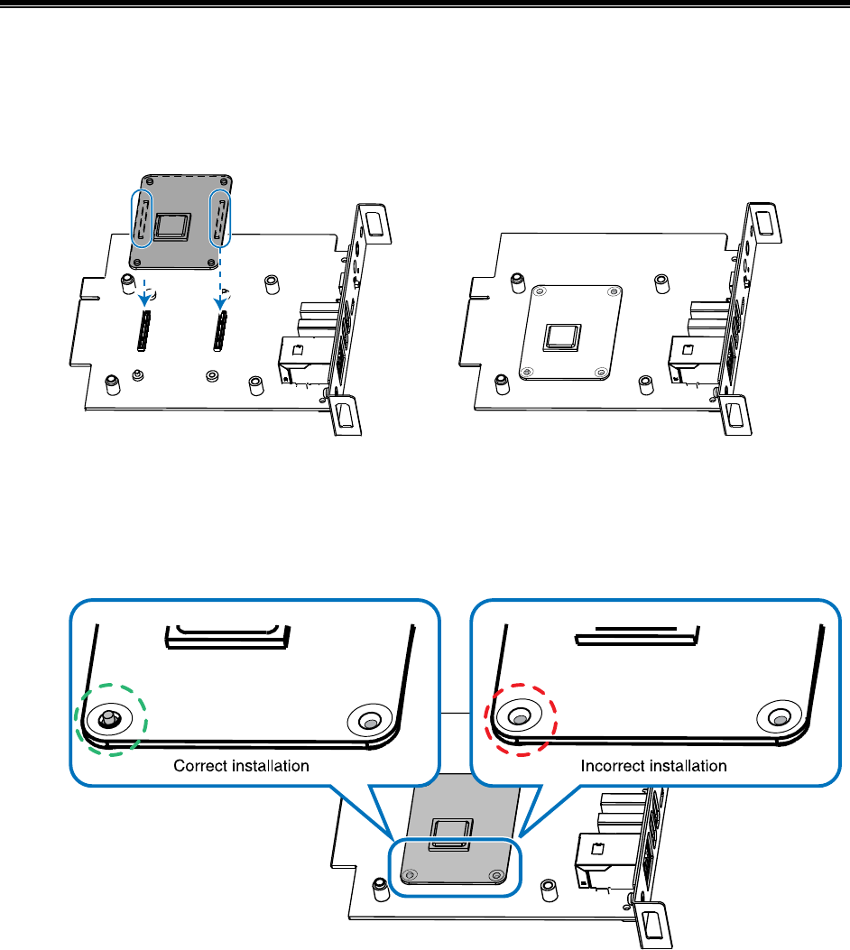
4. Check the distance between the Interface Board and Compute Module; it should be equal on all
sides.
Figure 2-3: Check all sides of the Compute Module on the Interface Board
5. (DS1-IF21CE interface board only.) If installing the antenna for wireless functionality, follow the
steps in Section 12 on page 69, then return to the following steps.
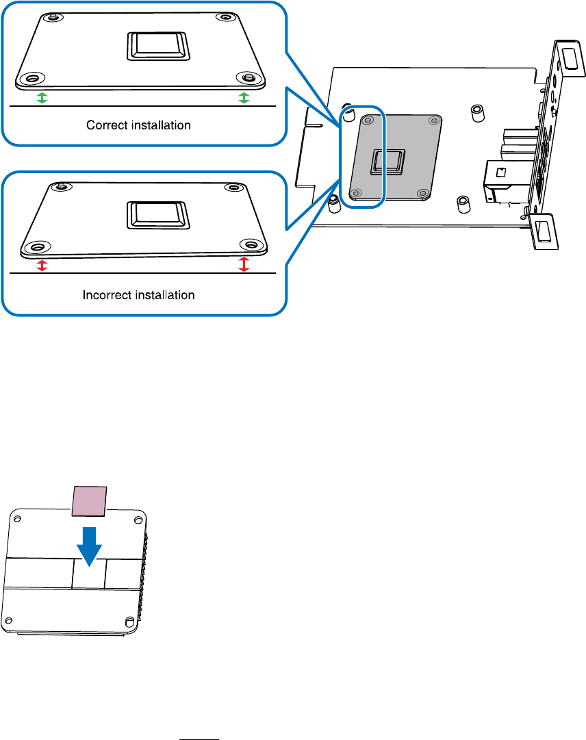
6. Peel the liner from one side of the thermal conductive sheet and stick the sheet to the
underside of the heatsink.
Important: Carefully align the thermal conductive sheet within the engraved marks before
adhering the sheet to the heatsink for proper alignment over the Raspberry Pi.
Figure 2-4: Place thermal conductive sheet
7. Peel the remaining liner from the thermal conductive sheet when you are ready to attach the
heatsink to the Compute Module Interface Board.
Important: Remove the liner before attaching the heatsink to the Interface Board.
©2021 Sharp NEC Display Solutions, Ltd. Page 16 of 86
8. Attach the heatsink using the four M3 screws supplied with the kit.
Important: Orientate the heatsink with the slotted hole in the bottom left corner before
attaching, as shown in the figure. The thermal conductive sheet will press against the top of the
Compute Module.
Figure 2-5: Attach the heatsink to the Interface Board
©2021 Sharp NEC Display Solutions, Ltd. Page 17 of 86
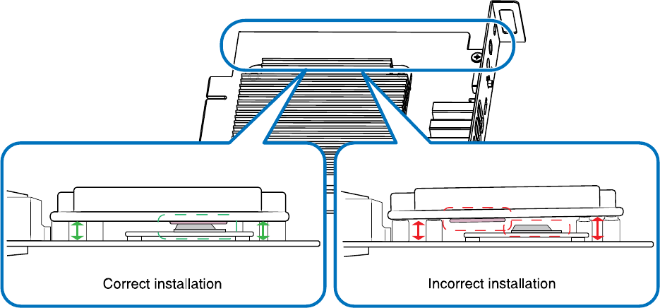
Confirm the heatsink is seated correctly by looking at the screw-hole posts on the Interface
Board. The two posts on the outside edge should be inserted and flush to the surface of the
heatsink. The heatsink rests on top of the two posts closest to the USB and LAN ports
connection.
Check the distance between the Interface Board and the heatsink; it should be equal on all sides,
the thermal sheet should press against the Compute Module, and the two screw-hole posts on
the outside edge should be inserted into the heatsink.
Figure 2-6: Check all sides of the heatsink
©2021 Sharp NEC Display Solutions, Ltd. Page 18 of 86
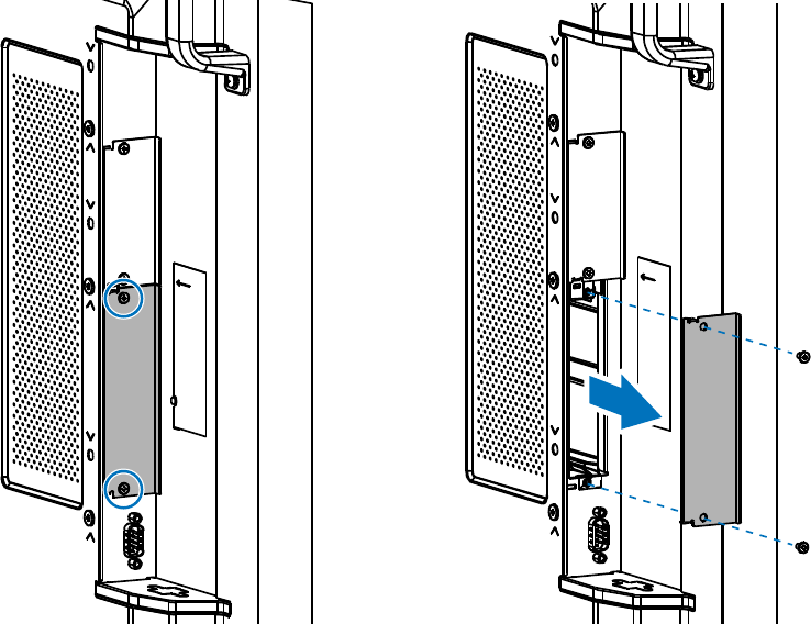
9. On the side of the display, remove the two screws holding the slot cover in place and then
remove the slot cover.
Note:
• Set the screws aside; they are used in the next step for securing the Compute Module
Interface Board in the display.
• Do not discard the slot cover. It helps to limit dust and debris from entering the display
and protect the internal components. Store it in a safe place for future use in case the
Compute Module Interface Board is removed from the display later.
Figure 2-7: Remove slot cover from the display
©2021 Sharp NEC Display Solutions, Ltd. Page 19 of 86
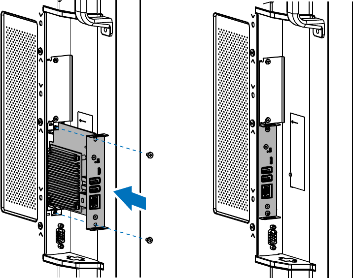
10. Insert the Interface Board into the slot. Make sure to carefully align and fully insert the Interface
Board into the slot and then secure it with the two screws removed in the previous step.
Figure 2-8: Insert the Interface Board in the display
11. Reconnect AC power to the display.
©2021 Sharp NEC Display Solutions, Ltd. Page 20 of 86
3 Connections and Internal Operation
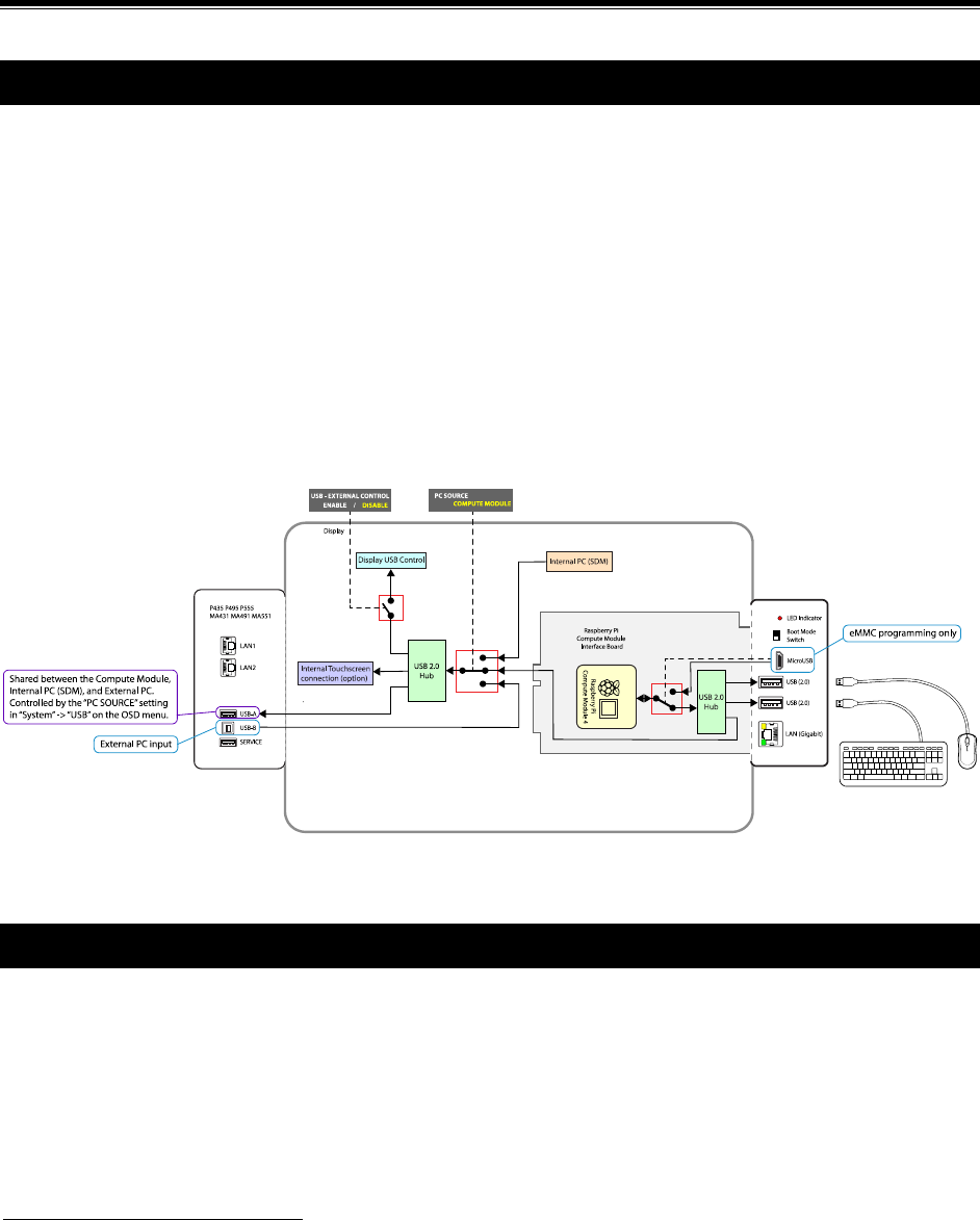
3.1 USB device connections to the Compute Module
The two USB Type-A inputs on the side of the Interface Board are for connecting downstream USB
devices, such as a keyboard and mouse, additional storage, external sensors and devices, or a Wi-Fi
adapter, to the Compute Module. Both connectors are USB 2.0 and can supply 500mA of current each.
On some display models
1
there is an additional USB input on the display itself labeled “USB-A” that can
be switched between the Compute Module, Internal PC (SDM), and an external PC connected to the
USB-B connection on the display. It can be configured via the display’s OSD “PC SOURCE” setting (see
section 6.18 on page 51) to switch automatically depending on the currently selected video input or fixed
to a specific source. This allows devices such as a mouse or other input device to be shared
automatically between different sources.
For display models
1
that have been integrated with an optional 3
rd
party touchscreen, the internal USB
connection from the touch sensor will also follow the “PC SOURCE” setting so that as video inputs on the
display are changed, the touchscreen connection will automatically switch to the correct source device.
Figure 3.1-1: USB Device Connection
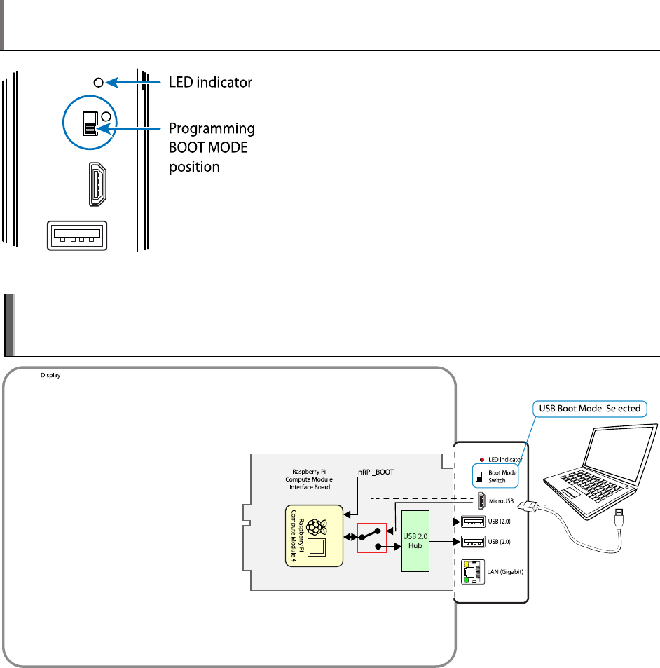
3.2 USB connections for programming the Compute Module
To program the Compute Module, an external “host” PC is connected to the USB Micro-B connector on
the Interface Board. The Boot Mode switch on the side of the Interface Board should be moved to the
position towards the USB connectors and the display powered on. After running the “rpiboot” utility, the
Compute Module 4 will then appear as a USB device to the “host” PC, allowing it to be programmed.
1
Current display models with a “USB-A” port on the terminal panel and PC SOURCE in the OSD menu: MA431,
MA491, MA551, P435, P495, P555
©2021 Sharp NEC Display Solutions, Ltd. Page 21 of 86
Note: The postion of the Boot Mode switch is only recognized when power is initially applied to the
Compute Module. Changing the position of the switch after power is applied to the Compute Module
does not affect its operating/boot mode.
Figure 3.2-1: BOOT MODE switch - programming mode
Important: Remove the cable connected to the USB Micro-B port and the host PC after programming
is complete. Failure to disconnect the cable may result in connected USB peripherals and the internal
LAN hub not being detected by the Compute Module.
Figure 3.2-2: Host USB Connection for Programming

©2021 Sharp NEC Display Solutions, Ltd. Page 22 of 86
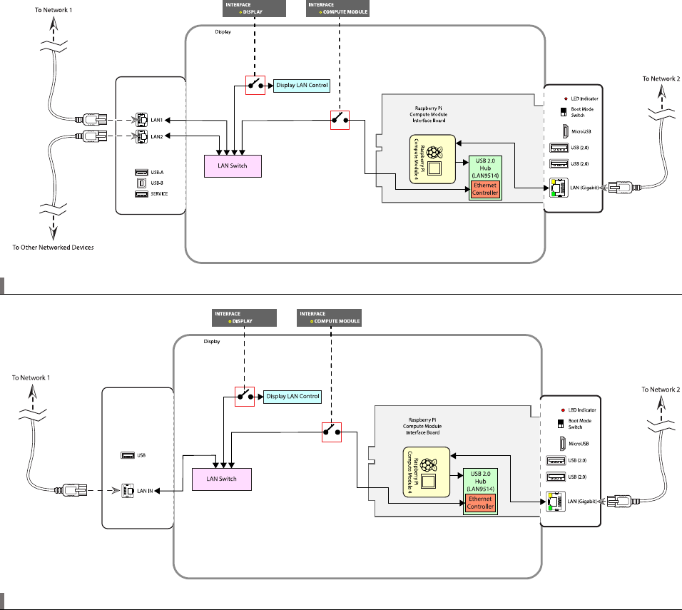
3.3 LAN connections
The Compute Module Interface Board features an onboard Gigabit LAN connection for direct high-speed
connection to the Compute Module.
Additionally, an internal 10/100 Mbps interface on the Interface Board and LAN switch within the display
provides network connectivity to both the display and Raspberry Pi Compute Module using a single
network connection.
• The display’s LAN control interface and the Compute Module will have their own IP address and
network settings and can be configured via the display’s OSD and internal web page.
• The IP address and network settings of the Compute Module are configured within the OS
running on it.
• (Multiple LAN port models only
1
) Two of the display’s LAN switch ports are available externally
for daisy-chaining other devices.
o LAN1 port should be used to connect to the network.
o LAN2 output can be used to daisy-chain connect other LAN devices or displays.
Note: The internal 10/100 Mbps interface uses LAN controller (LAN9514) connected to the Compute
Module via USB 2.0. It is necessary to enable USB host mode support on the OS to use this interface.
See 5.1 Enabling the onboard USB 2.0 controller on page 33 for more information.
Important: Both the Gigabit and 10/100 Mbps LAN interfaces will be assigned a MAC address based
on the serial number of the Compute Module. At the time of writing, Raspberry Pi OS will assign
identical MAC and IP addresses to both interfaces. This will lead to an illegal ethernet condition if both
network ports are connected to the same network and may result in degraded or no network
connectivity.
It is possible to assign a different MAC address to one of the network interfaces to avoid this. See
section 7.22 on page 58.
Note: The LAN2 connection should be used for connecting to other displays that are daisy-chained or to
other LAN devices. Functions such as AUTO ID and AUTO IP will not work correctly if displays are not
daisy-chained correctly using the LAN1 and LAN2 connections.
1
Current models with multiple LAN ports on the terminal panel: MA431, MA491, MA551, P435, P495, P555
©2021 Sharp NEC Display Solutions, Ltd. Page 23 of 86
Figure 3.3-1: LAN Connections Models: MA431 / MA491 / MA551 / P435 / P495 / P555
Figure 3.3-2: LAN Connections Models: M431 / M491 / M551 / M651 / ME431 / ME501 / ME551 / ME651

©2021 Sharp NEC Display Solutions, Ltd. Page 24 of 86
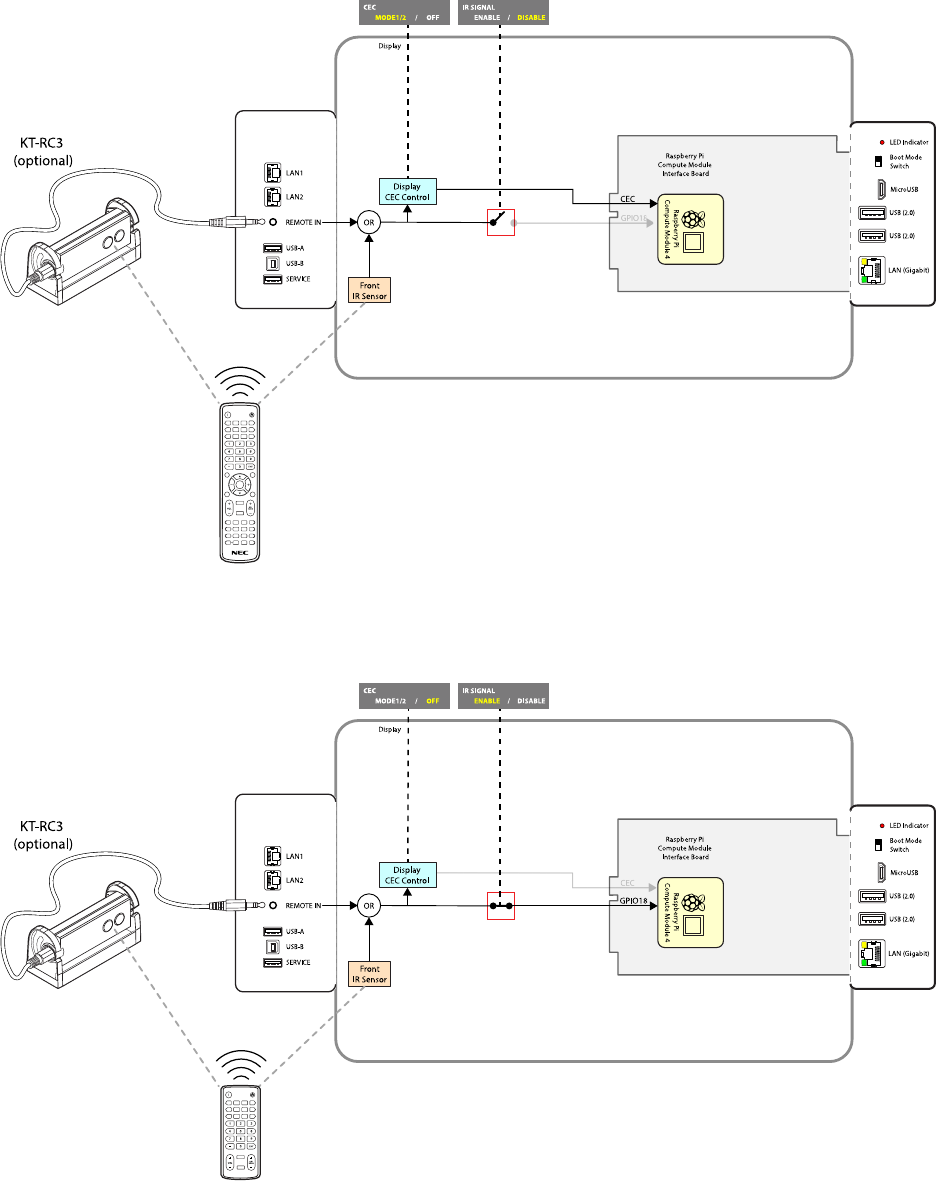
3.4 Software control via IR Remote
An IR Remote can be used to control software running on the Compute Module, such as a media player.
IR Remote signals are received via the display’s built-in remote control sensor or via an optional external
KT-RC3 sensor.
Note: The display’s built-in sensor will automatically be disabled when the external KT-RC3 sensor is
connected.
This feature can be used in two ways:
• As a CEC (Consumer Electronics Control) device
Specific buttons on the NEC IR Remote will perform actions, such as Stop, Play, Next, Previous,
etc., on CEC enabled software on the Compute Module. The display is responsible for receiving
and decoding the IR Remote signals, and then forwarding them on to the Compute Module as
standard CEC commands.
Only the NEC IR Remote can be used, and CEC support must be enabled on the display and in
the Operating System on the Compute Module. See Figure 5.15.1-3: Supported CEC buttons on
the NEC IR Remote in CEC MODE 1 on page Error! Bookmark not defined. and Figure 5.15.1-4:
Supported CEC buttons on the NEC IR Remote in CEC MODE 2 on page Error! Bookmark not
defined..
The buttons used for CEC commands are dual-function on the NEC IR Remote. When the
display’s OSD is active (being displayed) the buttons will perform display related functions.
When the OSD is not active the buttons will perform CEC functions. Press the EXIT button on the
IR Remote to exit and deactivate the OSD.
See section 6.16 on page 50 and section 6.17 on page 51 for more information.
• As a generic IR receiver
Demodulated raw IR signals received by the remote control sensor are passed to the Raspberry
Pi Compute Module via GPIO 18. Packages such as lirc can be used to decode the raw IR signals.
IR Remotes other than the NEC IR Remote, such as a standard MCE/RC6 type, can be used if
they use a 40 KHz carrier. See section 5.6 on page 36, section 5.7 on page 37, and section 6.5 on
page 45 for more information.
©2021 Sharp NEC Display Solutions, Ltd. Page 25 of 86
Figure 3.4-1: Using the NEC IR Remote with CEC
Figure 3.4-2: Using other IR Remotes with raw IR signals
©2021 Sharp NEC Display Solutions, Ltd. Page 26 of 86
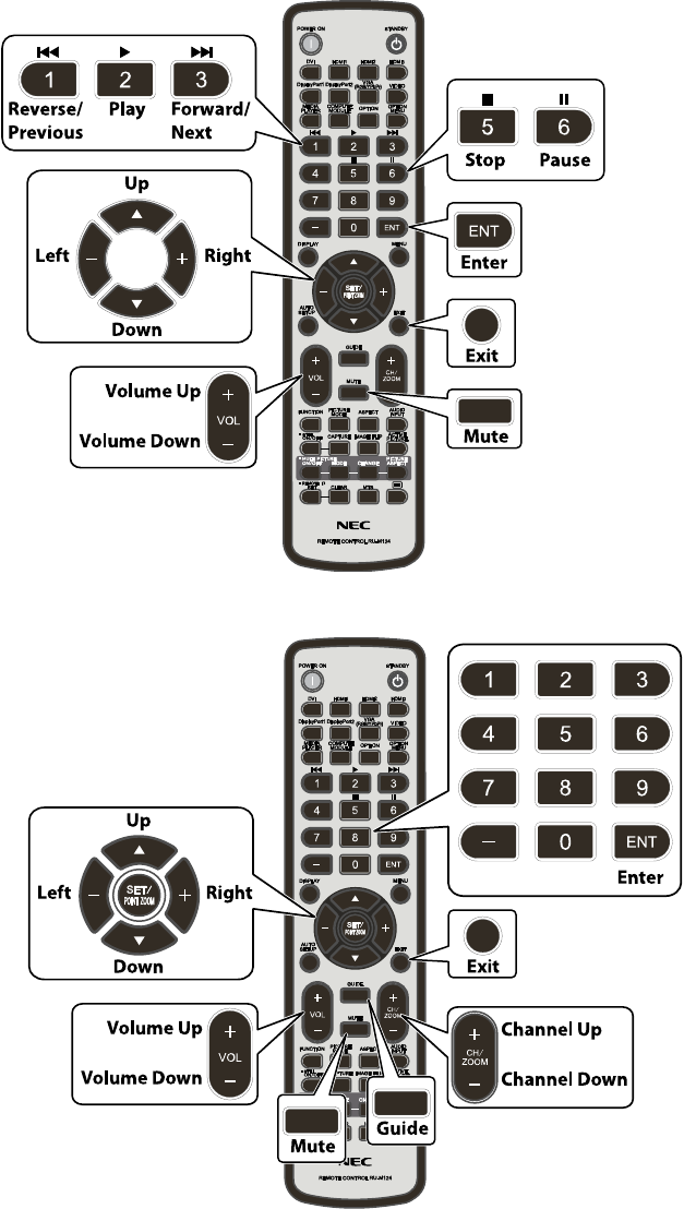
Figure 3.4-3: Supported CEC buttons on the NEC IR Remote in CEC MODE 1
Figure 3.4-4: Supported CEC buttons on the NEC IR Remote in CEC MODE 2
The mapping of buttons on the NEC IR Remote to CEC commands has two different modes that can be
selected via the OSD menu. Please see section 6.16 Input Advanced CEC CEC on page 50.
©2021 Sharp NEC Display Solutions, Ltd. Page 27 of 86
Note: The Volume Up, Down and Mute buttons will control audio on the display rather than on any
media player software running on the Compute Module. These buttons will only operate in CEC mode
if a CEC compatible audio amp/receiver is used.
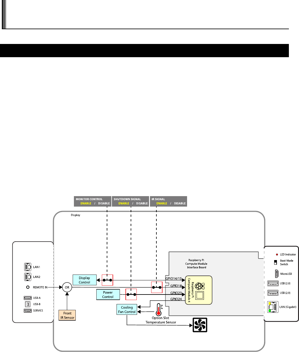
3.5 GPIO
The following GPIO are used for signaling between the display and Compute Module:
• GPIO 14 & 15 (UART0 TX & RX) – internal serial connection to the display for control. This can be
enabled and disabled via the OSD setting (see 6.11 Slot Compute Module Advanced
Setting Monitor Control on page 48.)
• GPIO 18 – (input to Compute Module) demodulated IR receiver from the display. This can be
enabled and disabled via the OSD setting (see 6.10 Slot Compute Module Advanced
Setting IR Signal on page 48.)
• GPIO 23 – (input to Compute Module) shutdown signal (goes low to signal the display is about to
shut down power to the Compute Module). This can be enabled and disabled via the OSD
setting (see 6.9 Slot Compute Module Advanced Setting Shutdown Signal on page 47.)
• GPIO 24 – (output from the Compute Module) cooling fan control (set high to force the display’s
cooling fans on).
Figure 3.5-1: GPIO
©2021 Sharp NEC Display Solutions, Ltd. Page 28 of 86
4 Preparing and running the tools to program the
Compute Module
The following steps explain how to use a Windows PC as a host system to program the Compute Module.
These steps will make the Compute Module appear as a mass storage device to the host PC so it can be
programmed with an OS image. Similar steps can be used for macOS and Linux based systems also –
please consult the Raspberry Pi documentation and website for the appropriate tools and steps.
4.1 Using a Windows PC as a host
1. Download and install either the official Raspberry Pi Imager application (recommended),
balenaEtcher or Win32DiskImager tool from the following locations. This will be used to write the
OS .img file to the Compute Module.
https://www.raspberrypi.org/software/
https://etcher.io/
https://sourceforge.net/projects/win32diskimager/
2. Download and install the Compute Module boot installer. This will install Windows drivers for
accessing the Compute Module as a mass storage device.
https://github.com/raspberrypi/usbboot/blob/master/win32/rpiboot_setup.exe
3. Download the OS image to be programmed to the Compute Module. The download may need to be
unzipped to reveal the .img file. Refer to the following section and the Raspberry Pi website for a list
of supported OSs:
https://www.raspberrypi.org/downloads/
4. A text editor that is compatible with UNIX type line endings, such as Notepad++, is highly
recommended for making boot configuration file changes from Windows. Notepad++ is available
from:
https://notepad-plus-plus.org/
5. Set the Compute Module to boot mode for programming.
To set programming boot mode:
a. Turn off the display’s AC power switch.
b. Connect a USB cable from the USB Micro-B connector on the Interface Board to the host PC.
c. Move the BOOT MODE switch on the Compute Module Interface Board terminal panel to
the programming boot mode position.
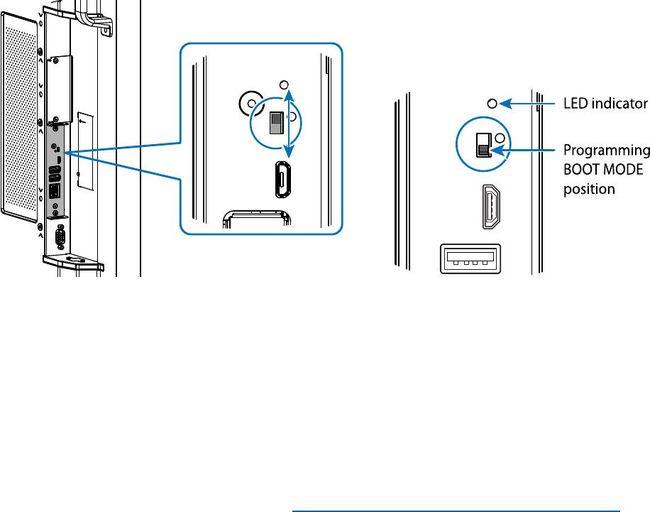
©2021 Sharp NEC Display Solutions, Ltd. Page 29 of 86
Figure 4.1-1: BOOT MODE switch - programming mode
d. Turn on the display’s AC power switch. Verify that the Compute Module is powered on.
Navigate the OSD to SLOT
COMPUTE MODULE POWER CONTROL POWER SUPPLY
and make sure ON is selected (displayed in yellow).
e. Verify that the Compute Module is powered on by looking at the LED indicator next to the
BOOT MODE switch. The LED should be red when power has been applied to the Interface
Board.
See the Troubleshooting section for “RPi Boot” is unable to detect the Compute Module
on
page 59 if the LED indicator does not illuminate.
6. Run the RPiboot application installed by the Compute Module boot installer by selecting “rpiboot”
from the Windows Start menu. A command window like the one shown below should appear and
close within a few seconds.
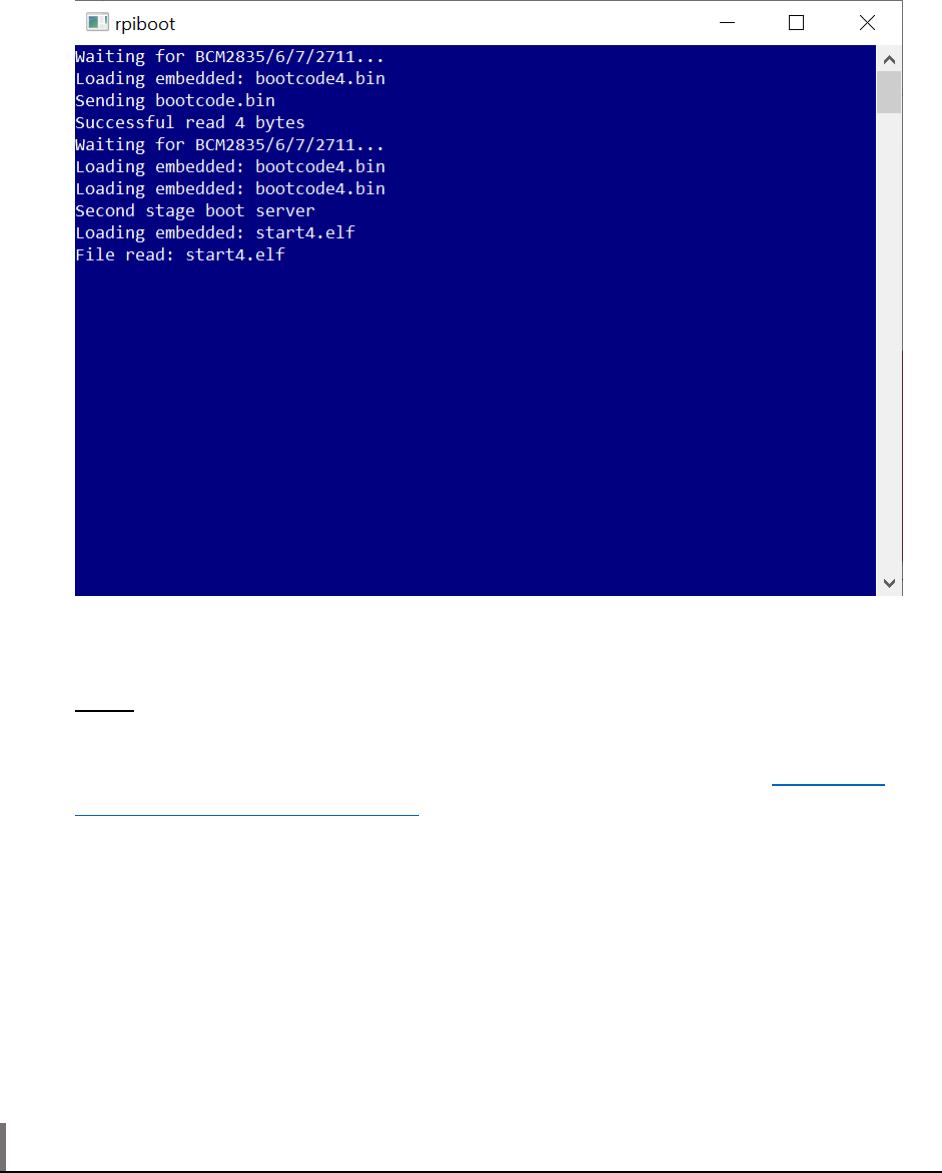
©2021 Sharp NEC Display Solutions, Ltd. Page 30 of 86
The indicator LED next to the BOOT MODE switch will turn from red to orange color.
At this point Windows may show a message that a new unformatted drive has been connected –
do not open or format the drive.
If the window stays open and displays only “Waiting for BCM2835/6/7/2711…” then the
Compute Module has not been detected. See the Troubleshooting section for
“RPi Boot” is
unable to detect the Compute Module on page 59.
7. Use the Raspberry Pi Imager, balenaEtcher, or Win32DiskImager tool to write the OS image file
a. Run the tool.
b. Select the downloaded OS .img file as the source image to write to the Compute Module.
c. Select the Compute Module “drive” as the target.
d. Click “Flash” or “Write” to begin writing and verifying the image. This process should take
approximately 5 to 15 minutes depending on the size of the OS image file.
e. When finished, the drive should contain the boot files for the OS.
Note: The imaging tool may “eject” the Compute Module’s drives when writing and verification is
complete. If so, disconnect and reconned the USB cable to the PC and the drives should reappear.
8. Configuring boot options:
©2021 Sharp NEC Display Solutions, Ltd. Page 31 of 86
Some settings in the boot files
config.txt and cmdline.txt can be modified at this stage.
For example, settings to correctly enable the USB 2.0 controller on the Compute Module, set the
video output level, and to enable the IR Remote module (lirc) can be made while still in
Windows.
Navigate to the drive letter of the Compute Module to see the boot files.
Use a text editor that is compatible with UNIX type line endings such as Notepad++
(https://notepad-plus-plus.org/
)
See section 5 on page 33 of this document for further information on specific configurations.
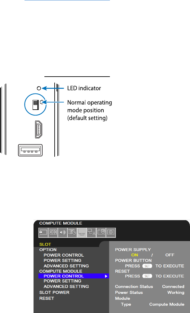
9. The Compute Module in the display can now be restarted in normal mode to boot the device.
a. Turn off the display’s AC power switch.
b. Disconnect the USB cable from the USB Micro-B connector on the Interface Board.
c. Move the BOOT MODE switch on the Compute Module Interface Board terminal panel to
the normal operating mode position.
Figure 4.1-2: BOOT MODE switch - normal mode
d. Turn on the display’s AC power switch.
e. Verify that the Compute Module is powered on. Navigate the OSD to SLOT COMPUTE
MODULE
POWER CONTROL POWER SUPPLY and make sure ON is selected (displayed
in yellow).
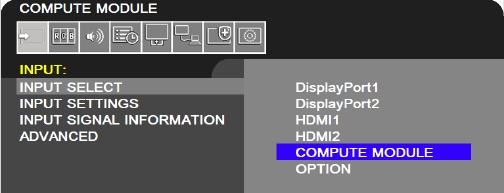
f. Make sure the Compute Module input on the display is selected.
©2021 Sharp NEC Display Solutions, Ltd. Page 32 of 86
The boot-up sequence for the OS programmed to the Compute Module should be seen on the screen
within a few seconds.
See the troubleshooting section on page 59 if no boot screen is seen.
10. Check for any system and firmware updates to the OS (Internet connection to the display or
Compute Module required). See section 7.7 on page 55.

©2021 Sharp NEC Display Solutions, Ltd. Page 33 of 86
5 Miscellaneous Configuration Items
Note: Many of the options for the Raspberry Pi OS can be automatically configured using the
Compute Module Configuration Tool for Raspberry Pi OS see “Compute Module Configuration Tool for
Raspberry Pi ” on page 67.
5.1 Enabling the onboard USB 2.0 controller
The default settings on Raspberry Pi OS do not enable the USB 2.0 controller in host mode. This
prevents any USB peripherals, including the onboard USB LAN controller (LAN9514), from operating.
To enable the enable the USB 2.0 controller in host mode add the following line to the config.txt file:
dtoverlay=dwc2,dr_mode=host
5.2 Enabling 4K@60Hz video output
The default settings on Raspberry Pi OS do not enable the 4K@60Hz video signal format, and the output
format may be limited to 4K@30Hz.
To enable the 4K@60Hz format add the following line to the config.txt file:
hdmi_enable_4kp60=1
Note: For the best screen image use the display’s native 4K resolution of 3840x2160.
5.3 Configuring the correct HDMI video level encoding and decoding
The Compute Module can output video to displays that have video levels either in the range 0-255
(known as “full”) or in the range 16-235 (known as “limited” or “RGB limited”). Configuration settings for
the OS determine which range will be output. The NEC display can accept either range sets and will
display the video correctly, as long as it is correctly configured to match the video range from the
Compute Module. However, it is recommended to use the “full” range since it will give the maximum
number of displayable colors.
A mismatch between the output range from the Compute Module and the display will result in either:
• Blacks appearing as gray and whites being too dark.
o Cause: Compute Module outputs “limited” video range and the display is set to “FULL”.
Or
• Dark gray levels being crushed and whites being clipped.
o Cause: Compute Module outputs “full” video range and the display is set to “LIMITED”.
The video range used by the display is configured as follows:
1. Navigate to the INPUT menu on the OSD.
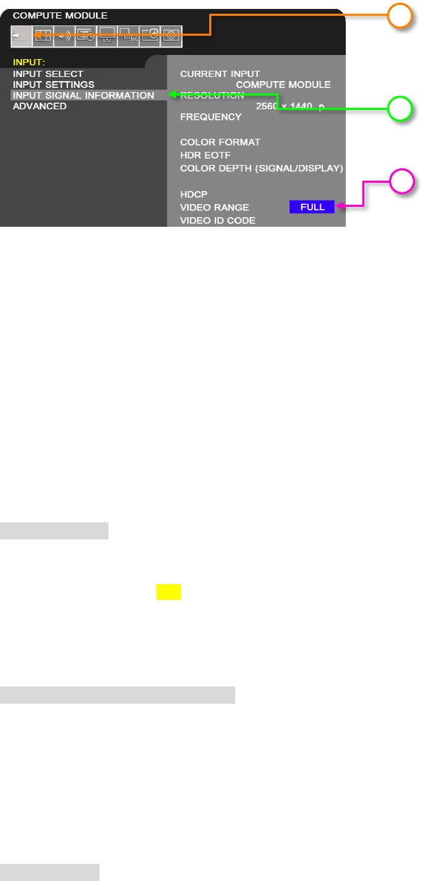
©2021 Sharp NEC Display Solutions, Ltd. Page 34 of 86
2. Select INPUT SIGNAL INFORMATION.
3. The VIDEO RANGE setting determines how the display will handle the video from the Compute
Module.
• FULL - Use FULL if the Compute Module is configured to output “full” video in the range 0-
255. This is the recommended configuration since it provides the maximum number of
displayable colors. The display will not modify the range of the video signal levels.
• LIMITED - Use LIMITED if the Compute Module is configured to output “limited” video in the
range 16-235. The display will expand the video from the range 16-235 to 0-255 internally.
The video range used by the Compute Module depends on the Operating System. By default and
depending on the OS, many distributions will automatically output a video signal to the display that uses
video levels 16 to 235. A configuration file or menu setting is used to configure the video level.
For Raspberry Pi OS and many other OS distros, the current video settings can be confirmed by typing
the following into a terminal window:
tvservice –s
The output should show something similar to the following:
“HDMI CEA (16) RGB lim 16:9, 1920x1080 @ 60.00 Hz, progressive”
If “lim” is shown, it means that limited 16 – 235 video is being output to the display.
To change this setting, a configuration file must be edited. If changing the setting from the Compute
Module itself, use the built in text editor “Nano” to edit the config.txt file:
sudo nano /boot/config.txt
Scroll to the end of the file and enter the following line:
hdmi_pixel_encoding=2
Save the file by pressing CONTROL + o then ENTER
Exit Nano by pressing CONTROL + x
Restart the Compute Module by typing:
sudo reboot
1
3
2

©2021 Sharp NEC Display Solutions, Ltd. Page 35 of 86
When rebooted, confirm the video levels are correct by using the following command again:
tvservice –s
The output should now show “full”
“HDMI CEA (16) RGB full 16:9, 1920x1080 @ 60.00 Hz, progressive”
5.4 To disable overscan (if black bars are visible on the sides of the
screen)
Either
• Run the Raspberry Pi Config utility from the terminal
sudo raspi-config
Select: 9 Advanced Options
Select: A1 Overscan
Select: No
Or
• Edit the config.txt file to disable overscan:
sudo nano /boot/config.txt
Look for the following section:
# uncomment this if your display has a black border of unused pixels
visible
# and your display can output without overscan
#disable_overscan=1
Edit the last line to remove the #.
disable_overscan=1
Save the file and reboot.
5.5 To rotate the screen image to portrait orientation
Use the Screen Configuration tool available on the OS Preferences menu. Select the screen and select
Orientation. Change the setting to “Left”. This will match the display being physically rotated
counterclockwise into portrait orientation.
Important: Using the display rotated clockwise is not approved due to the cooling design.
©2021 Sharp NEC Display Solutions, Ltd. Page 36 of 86
Note: The orientation of the display’s OSD can be changed to match by changing the SYSTEM OSD
OSD ROTATION setting.
5.6 To enable support for the IR Remote receiver using “lirc”
1. Make sure the display support is enabled.
a. On the NEC display select the SLOT menu on the OSD.
b. Select the ADVANCED SETTINGS option after COMPUTE MODULE.
c. Confirm that the IR SIGNAL is set to ENABLE.
2. Edit the config.txt file to enable support for lirc:
sudo nano /boot/config.txt
a. Look for the following section:
#uncomment this to enable the lirc-rpi module
#dtoverlay=lirc-rpi
b. If present, edit the last line to remove the # otherwise add the following line to the end
of the list:
dtoverlay=lirc-rpi
c. Save the file by pressing CONTROL + o then ENTER.
d. Exit Nano by pressing CONTROL + x.
Notes:
• A reboot is usually necessary to enable support.
• If lirc support is not included with the OS, it can be installed using the following:
sudo apt install lirc
a
b
c
©2021 Sharp NEC Display Solutions, Ltd. Page 37 of 86
• Additional configuration may be required in the OS and application being used.
5.7 To test support for the IR Receiver by outputting raw data
Make sure lirc is installed using:
sudo apt install lirc
Output raw data from the IR receiver as follows:
sudo /etc/init.d/lirc stop
mode2 -d /dev/lirc0
Point an IR Remote at the IR sensor on the display and press some buttons. Output should be seen
showing the raw pulses received.
5.8 To enable the serial port (UART) to the display and allowing
application access
To enable the UART communications with the display so that applications on the Compute Module can
communicate with the display:
1. On the NEC display navigate to the SLOT menu on the OSD.
2. Select the ADVANCED SETTINGS options after COMPUTE MODULE.
3. Confirm that the MONITOR CONTROL is set to ENABLE.
4. Edit the config.txt file to allow application access to the serial port, by editing to either add or
change so there is a line with:
enable_uart=1
1
2
3
©2021 Sharp NEC Display Solutions, Ltd. Page 38 of 86
5. Edit the cmdline.txt file to allow app access to the serial port and prevent bootup information
being sent to the display by removing any section with:
console=serial0,115200
Important: When the Raspberry Pi boots up, all the bootup information can be sent to the serial port
for debugging purposes. Since this serial port is connected internally to the display, this may
overwhelm the display and cause erratic behavior (such as the OSD flashing, random operations
being performed, slow bootup of the Compute Module, etc.). If the internal connection is enabled (the
MONITOR CONTROL setting on the COMPUTE MODULE ADVANCED SETTINGS menu of the
OSD is set to ENABLE) then the bootup information must be disabled.
5.9 Testing internal serial communications to the display using the
Python based NEC PD SDK
1. Install the Python based NEC PD SDK files, and download the examples. See Python Based NEC
PD SDK on page 65.
2. If necessary, install the Python serial module. This should normally be automatically installed.
sudo apt install python-serial
3. Run the test file in the SDK.
python test_routines_example.py
4. The application should output information about the display, such as model name and serial
number.
Note: Confirm the MONITOR CONTROL is set to ENABLE on the OSD.
5.10 Configuring the Compute Module to shutdown using shutdown
signal from the display
To enable the Shutdown Signal from the display:
1. On the NEC display navigate to the SLOT menu on the OSD.
2. Select the ADVANCED SETTINGS options after COMPUTE MODULE.
3. Confirm that the SHUTDOWN SIGNAL is set to ENABLE.
©2021 Sharp NEC Display Solutions, Ltd. Page 39 of 86
Raspberry Pi OS includes an overlay for directly monitoring a GPIO used for signaling system shutdown.
The configuration settings can be made directly to the “config.txt” file by adding a line such as the
following example:
dtoverlay=gpio-shutdown,gpio_pin=23
See the following information for configuring the various boot overlay options:
https://github.com/raspberrypi/firmware/blob/master/boot/overlays/README
Alternatively, an example Python script rpi_shutdown.py is included with the Python based NEC PD
SDK. The script shows how to monitor GPIO 23 for a high to low transition, and how to use this to
gracefully shutdown the Operating System on the Compute Module before power to the module is
removed by the display. Normally this script should be started when the Operating System starts. This
can be accomplished by adding it to the /etc/rc.local file on the system. See the instructions
provided in the sample file for more details.
5.11 Reading and setting the display’s internal Real Time Clock (RTC)
from the OS
The Compute Module does not include a Real Time Clock, so the correct time must be configured at each
startup. This is usually done via a network connection to an NTP time server; however, the Compute
Module can read the display’s internal Real Time Clock as well.
The display’s internal Real Time Clock can be read and set from the Compute Module via the internal
serial connection (UART). This can be useful in situations where the Compute Module is unable to get the
current time from the network.
The Python based NEC PD SDK includes the following sample files:
1
2
3
©2021 Sharp NEC Display Solutions, Ltd. Page 40 of 86
•
set_system_to_display_clock.py - Reads the display’s internal clock via the internal
serial connection and sets the system time accordingly. This file can be added to a startup script
on the system, if necessary, to set the OS time from the display if no network connection is
available.
•
set_display_to_system_clock.py - Sets the display’s internal clock based on the current
system time on the Compute Module.
See the files included in the SDK for more details. See Python Based NEC PD SDK on page 65.
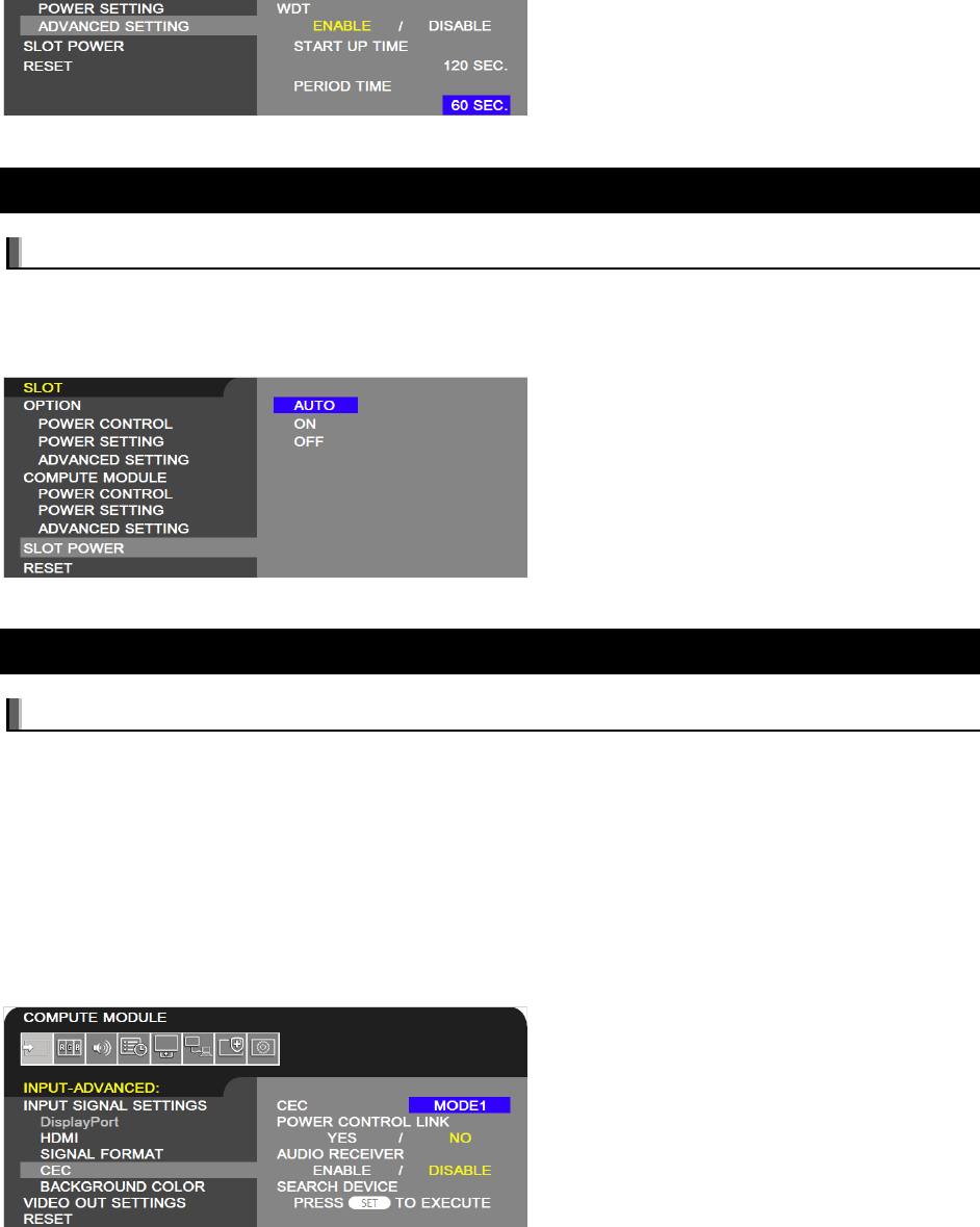
5.12 Using the display’s Watchdog Timer (WDT)
The display features an internal Watchdog Timer that can be used to automatically restart the Compute
Module if it stops responding; for example, if it hangs for some reason.
To use this feature, a background application is configured to periodically send reset commands to the
display via the internal UART. The display will expect to receive these reset commands as an indication
that the Compute Module is functioning normally. If, for some reason, the reset commands are not
received as expected the display will send a reset signal to the Compute Module.
Use of the Watchdog Timer is optional and requires configuring the Operating System to start the
background application at bootup. The Watchdog Timer is enabled and configured via the OSD or
communications commands. The background application must send the reset command at least as often
as the Period Time configured via the OSD. If three consecutive reset commands are not received, the
display will send a reset signal to the Compute Module.
There are two time periods that can be configured for the Watchdog Timer:
• Start Up Time – This sets the time delay for when the display should start receiving WDT reset
commands, via the internal UART, after power is applied to the Compute Module.
This timer’s value should be set high enough to include time for the operating system to fully
load on the Compute Module, and for the periodic reset commands to begin sending to the
display.
• Period Time – This sets the maximum amount of time within which the display must receive
WDT reset commands from the Compute Module, via the internal UART. If three consecutive
reset commands are missed, the display will restart the Compute Module.

©2021 Sharp NEC Display Solutions, Ltd. Page 41 of 86
This timer’s value should be set high enough to ensure that any software running on the
Compute Module will be able to send the periodic reset command to the display, even under
heavy load conditions.
The Python SDK includes support for sending the Watchdog Timer reset commands to the display, as
well as configuring the timer settings. See the example file reset_display_wdt.py included in the
SDK for more details. See Python Based NEC PD SDK on page 65.
See sections 6.12 on page 48 through 6.14 on page 49 for details on configuring the Watchdog Timer
settings via the OSD.
5.13 Controlling the Compute Module power
Power to the Compute Module can be set to turn on automatically when the display power is turned on,
manually via the OSD, or manually via a command to the display. See section 6.2 on page 44 for details.
When the display power is turned off, the Compute Module power can remain on, or automatically shut
down and turn off with the display. See section 6.5 on page 45 for details.
Important: To avoid possible file system corruption, it is highly recommended to use the Shutdown
Signal to gracefully shutdown the system. See section 5.10 on page 38 for details.
5.14 Controlling the cooling fan automatically based on the CPU
temperature
The display’s cooling fan is automatically turned on based on a temperature sensor located near the
Interface Board. However, if desired, it can also be directly controlled based on the actual Compute
Module’s internal CPU temperature.
Use the Raspberry Pi Configuration tool available from the system menu and select the “Performance”
tab. Enable the fan setting, change the Fan GPIO to 24, and enter the desired temperature for the fan to
start operating. Note that a reboot will be required for the settings to be enabled.
Alternately, the settings can be made directly to the “config.txt” file by adding a line such as the following
example:
dtoverlay=gpio-fan,gpiopin=24,temp=70000
This sets the threshold temperature to 70°C and uses GPIO 24 to signal the fan.
See the following information for configuring the various boot overlay options:
https://github.com/raspberrypi/firmware/blob/master/boot/overlays/README
©2021 Sharp NEC Display Solutions, Ltd. Page 42 of 86
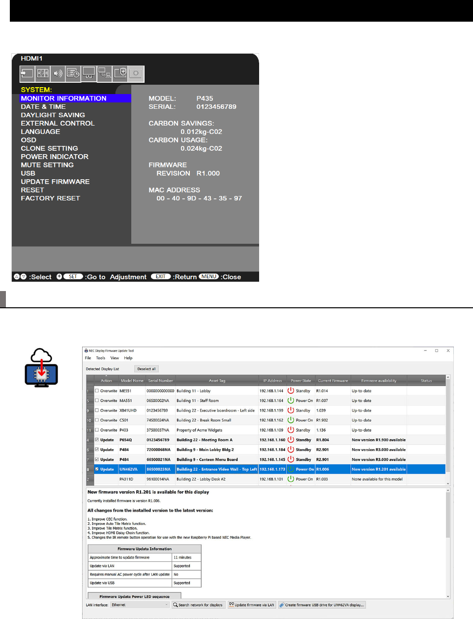
5.15 Checking and updating the display firmware version
The display firmware version is shown on the SYSTEM MONITOR INFORMATION menu on the OSD.
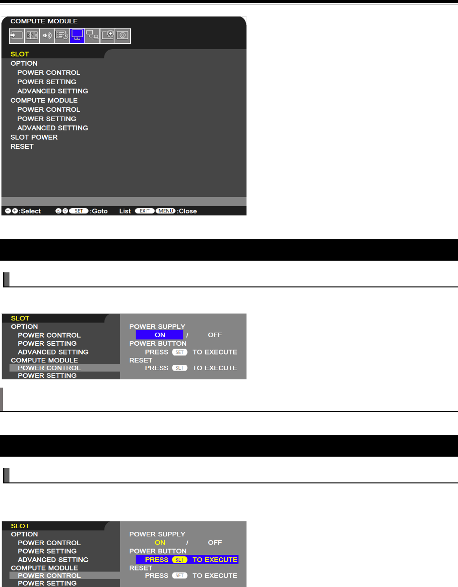
5.15.1 Update using the NEC Display Firmware Update Tool for Windows
The NEC Display Firmware Update Tool is a utility to assist with updating the firmware in large-screen
NEC LCD displays and some models of desktop NEC LCD displays.

©2021 Sharp NEC Display Solutions, Ltd. Page 43 of 86
Main features of the NEC Display Firmware Update Tool:
• Automatically locates networked NEC display models and determines if newer firmware is
available.
• Details of the changes between the installed firmware and the latest version are listed.
• Automatically downloads and verifies the latest firmware. Firmware can be downloaded for off-
line use if needed.
• For models that can be updated via LAN, the update process is almost fully automated and the
progress and estimated remaining time is shown.
• Up to 20 displays can be updated via LAN simultaneously. Other displays are queued until an
update slot becomes available.
• For models that are updated via USB, the correct firmware is copied to a USB drive and
instructions on how to update are displayed.
The latest version of the utility and instructions can be downloaded from the following location:
https://www.sharpnecdisplays.us/support-and-services/necdisplayfirmwareupdatetool/254
5.15.2 Update display firmware using a USB storage device
The latest display firmware can be downloaded from the following location:
https://www.sharp-nec-displays.com/dl/en/dp_soft/pd_fm_update/index.html
©2021 Sharp NEC Display Solutions, Ltd. Page 44 of 86
6 Related OSD Settings
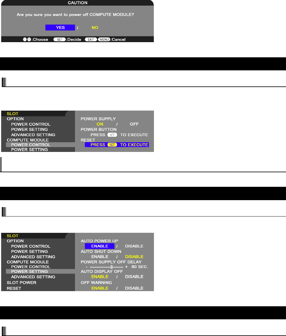
6.1 Slot Compute Module Power Control Power Supply
Available options: On / Off
Controls power to the Compute Module.
Note: The option that is yellow under POWER SUPPLY when opening the POWER CONTROL menu
indicates the current power status. If ON is yellow, the power is on. If OFF is yellow, the power is off.
6.2 Slot Compute Module Power Control Power Button
Available options: (SET command function only)
Performs a normal shutdown of the Compute Module. Press the SET button on the IR Remote with this
function highlighted.
©2021 Sharp NEC Display Solutions, Ltd. Page 45 of 86
6.3 Slot Compute Module Power Control Reset
Available options: (SET command function only)
Forces a shutdown and restart of the Compute Module when it does not respond to a shutdown using the
POWER BUTTON function. Press the SET button on the IR Remote with this function highlighted.
Note: This function may corrupt data files on the Compute Module and data files on any storage device
connected to the Compute Module interface card.
6.4 Slot Compute Module Power Setting Auto Power Up
Available options: Enable / Disable
The Compute Module will be turned on automatically when the display power is turned on.
6.5 Slot Compute Module Power Setting Auto Shutdown
Available options: Enable / Disable
Selects how power to the Compute Module is managed when the display switches to standby mode.
• Enable – When the display is turned off, power to the Compute Module will also be turned off. If
AUTO SHUTDOWN is enabled, this will be performed first to allow the system to gracefully shut
down before power is removed.
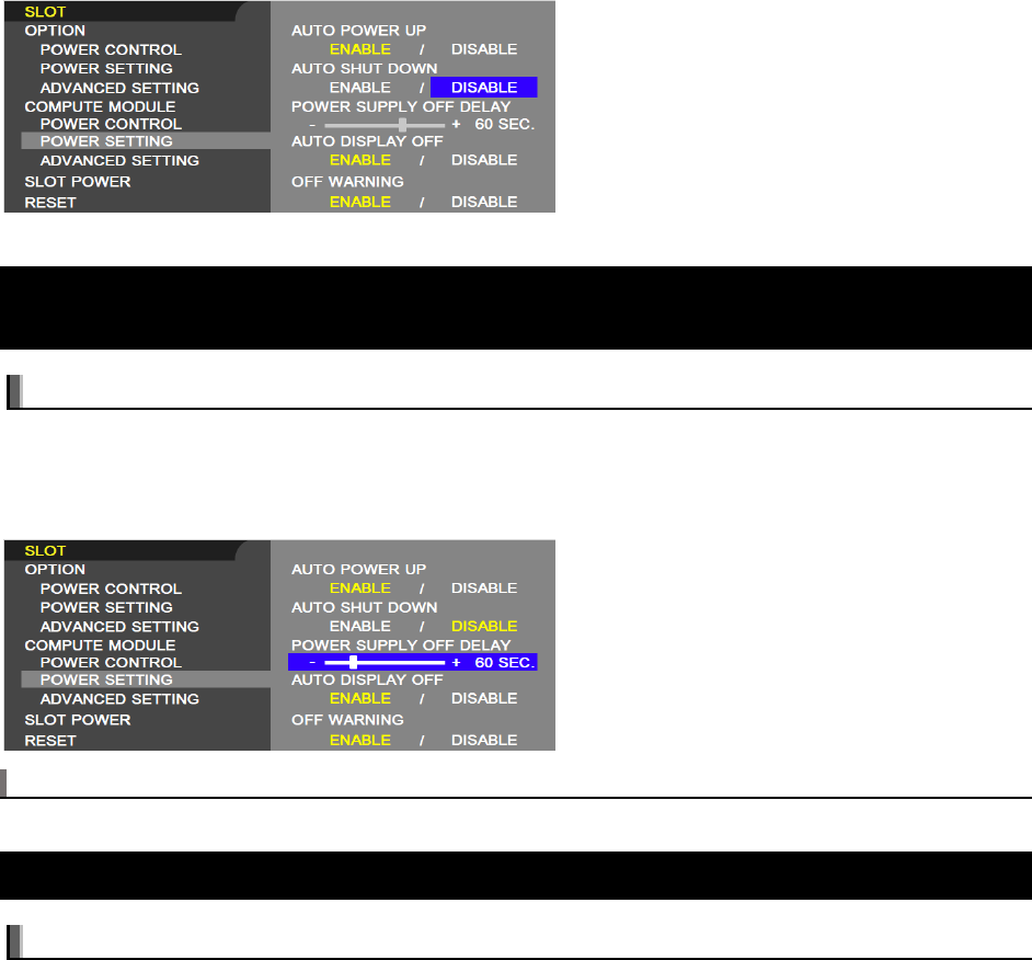
©2021 Sharp NEC Display Solutions, Ltd. Page 46 of 86
• Disable (Default) – Power to the Compute Module will remain on even when the display is in
standby mode.
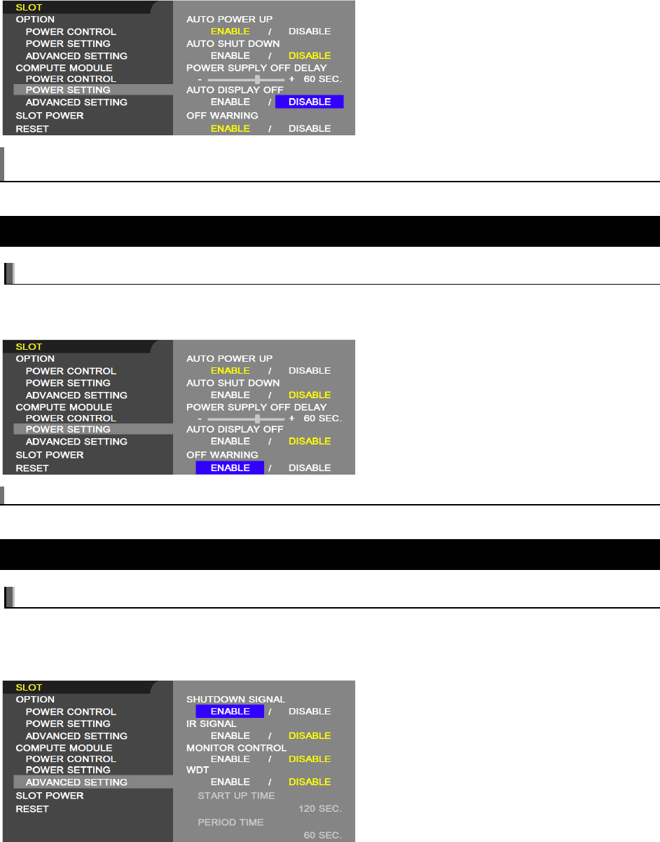
6.6 Slot Compute Module Power Setting Power Supply Off
Delay
Available options: adjustable between 30 – 600 seconds
This sets the time delay after the Shutdown Signal is set until the power to the Compute Module is turned
off. Configure this to allow adequate time for any software to shutdown safely.
Note that a monitoring utility must be installed to watch the GPIO 23 shutdown signal.
Note: For use only when the AUTO SHUTDOWN is set to ENABLE.
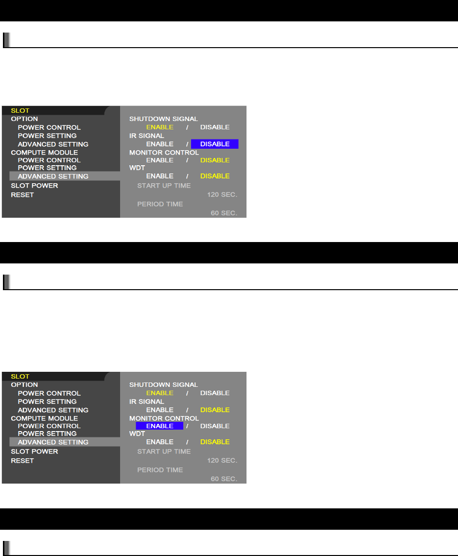
6.7 Slot Compute Module Power Setting Auto Display Off
Available options: Enable / Disable
Allows the display to switch into standby power save mode when the Compute Module signals that it has
transitioned into shutdown via the RUN_PG signal. Note that this signal is only output from the Compute
Module if the following settings are made to the Compute Module 4’s EEPROM:
WAKE_ON_GPIO=0
POWER_OFF_ON_HALT=1
Please see the documentation from Raspberry Pi for instructions on how to change the Compute
Module’s EEPROM settings.
©2021 Sharp NEC Display Solutions, Ltd. Page 47 of 86
Note: If you select ENABLE, the display power will not automatically be turned on when the Compute
Module turns on.
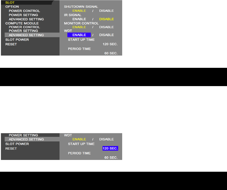
6.8 Slot Compute Module Power Setting Off Warning
Available options: Enable / Disable
When enabled, a warning will be shown when shutting down the power to the Compute Module that the
Compute Module should be turned off from within the OS.
Note: This function is available when POWER SUPPLY is OFF.
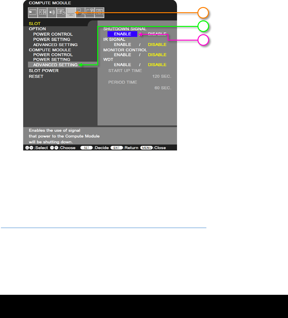
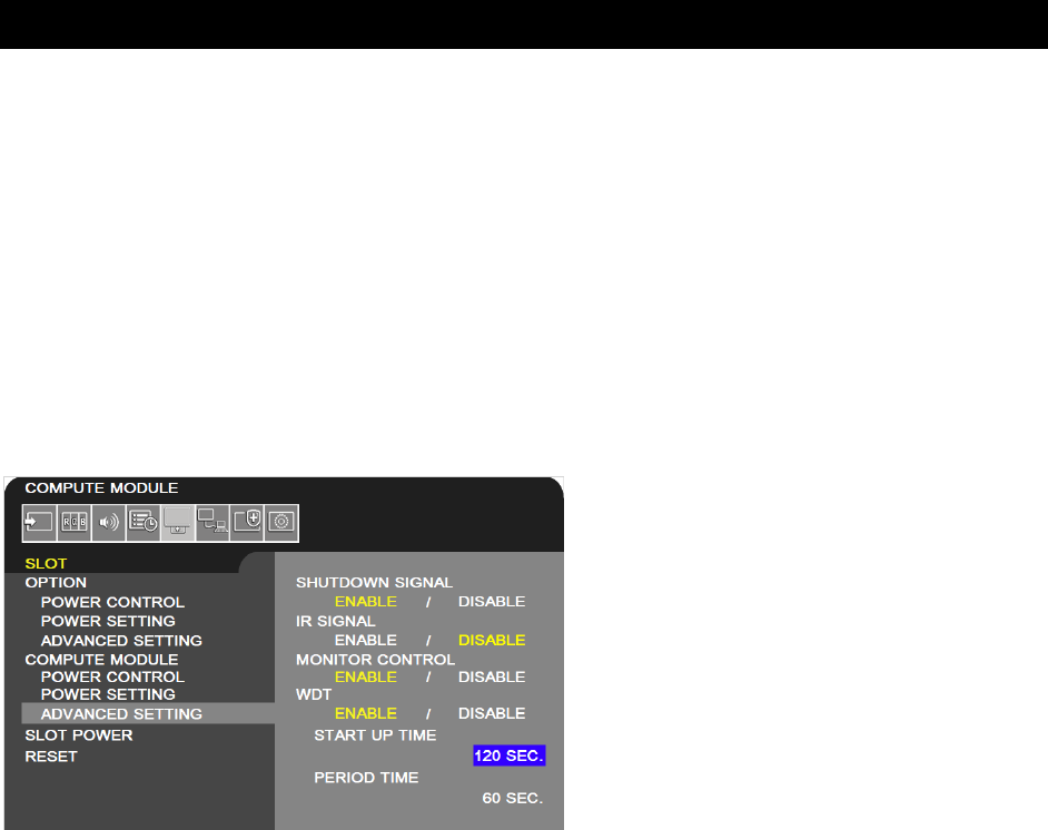
6.9 Slot Compute Module Advanced Setting Shutdown Signal
Available options: Enable / Disable
Enables or disables the use of GPIO 23 to signal that power to the compute module will be shutting down.
Note that a monitoring utility must be installed to watch the GPIO 23 shutdown signal and shut down the
operating system accordingly.
See Section 5.10 on page 38 for information on configuring the operating system support.
©2021 Sharp NEC Display Solutions, Ltd. Page 48 of 86
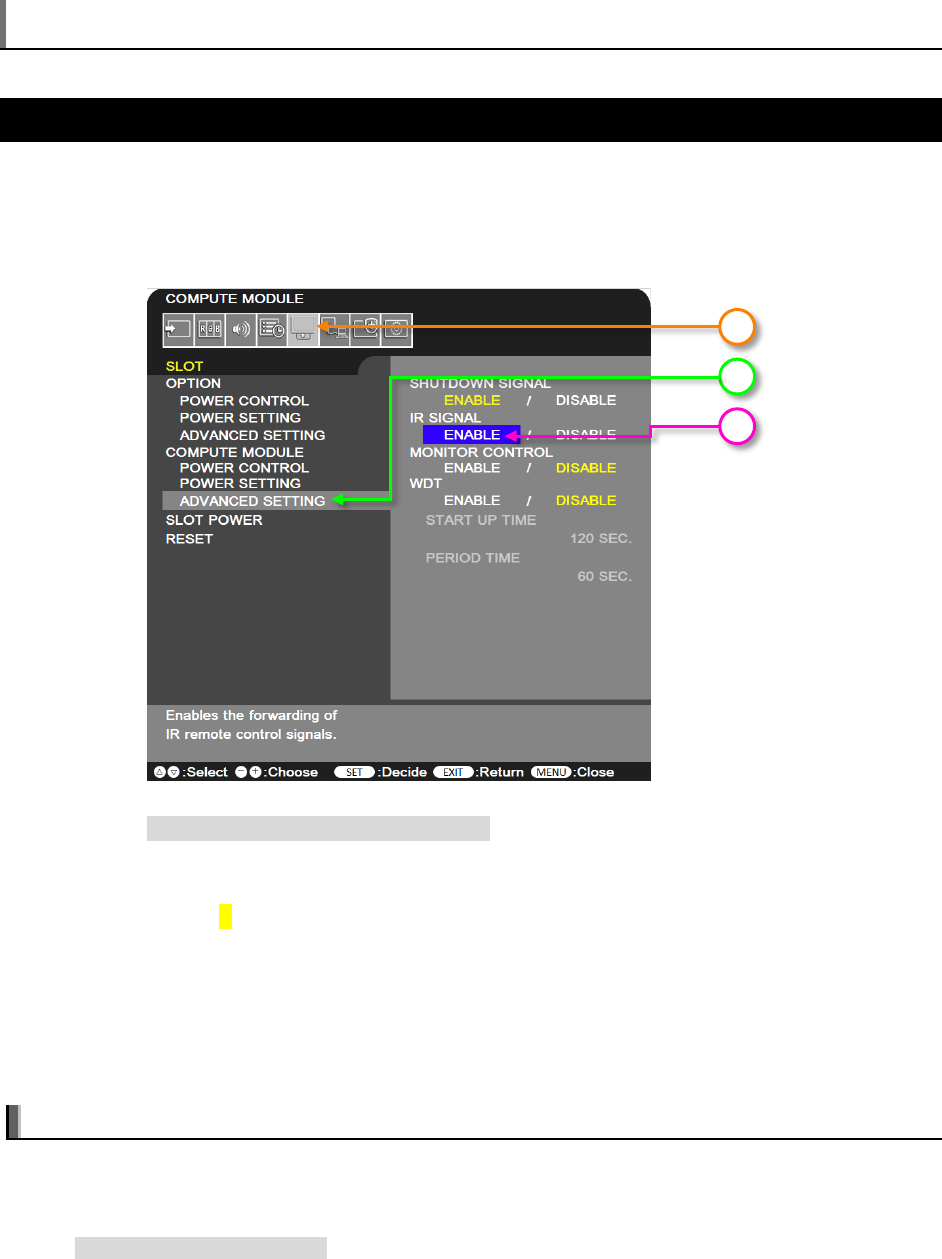
6.10 Slot Compute Module Advanced Setting IR Signal
Available options: Enable / Disable
Enables or disables the forwarding of IR Remote signals, received from the display’s internal remote
control sensor and optional external IR sensor, to the Compute Module via GPIO 18.
See section 3.4 Software control via IR Remote on page 24 for more details on using this feature.
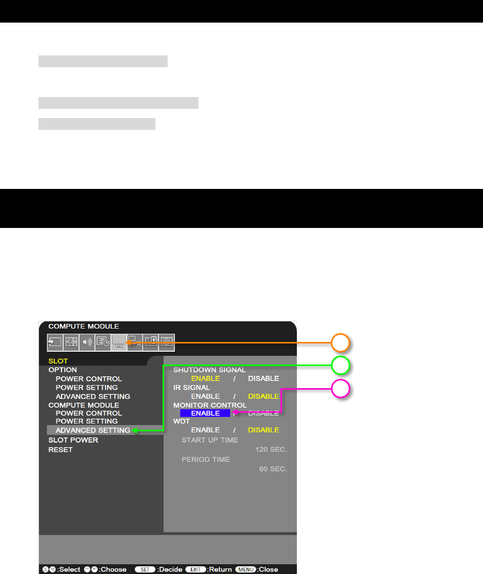
6.11 Slot Compute Module Advanced Setting Monitor Control
Available options: Enable / Disable
Enables or disables the internal serial connection between the display and Compute Module. If set to
Enable, communications is available via GPIO 14 & 15. This GPIO will normally appear as a TTY device.
Make sure the Operating System does not send boot console debug messages to the UART serial port; it
may cause erratic behavior in the display (such as the OSD flashing, random operations being performed,
slow bootup of the Compute Module, etc.).
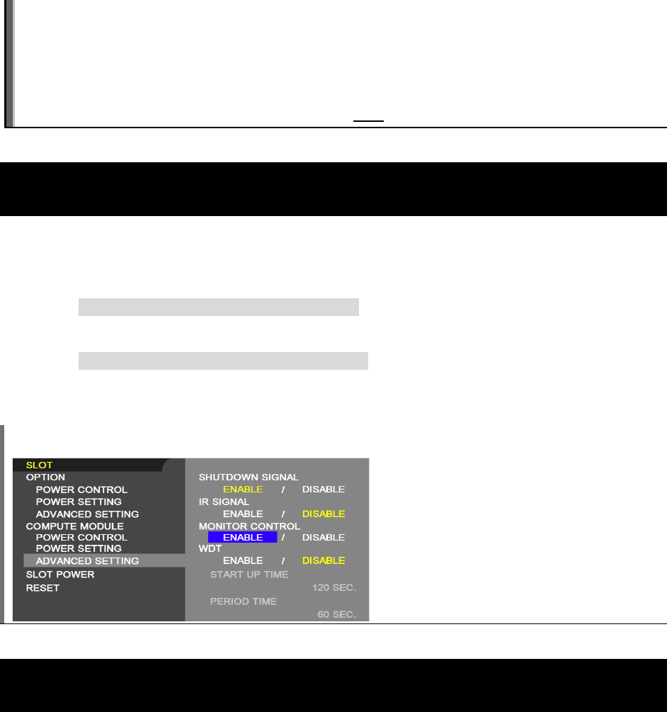
6.12 Slot Compute Module Advanced Setting WDT
Available options: Enable / Disable
Enables or Disables the display’s built in Watchdog Timer function for the Compute Module.
When set to Enable, the display will expect to receive a periodic reset command from the Compute
Module via the internal UART. If the command is not received for three consecutive timeout periods, the
display will restart the Compute Module.
©2021 Sharp NEC Display Solutions, Ltd. Page 49 of 86
This feature can be used to automatically reset the Compute Module if the CPU hangs for some reason.
The following two settings control the timeout periods: Start Up Time, Period Time
The Python SDK includes sample functions to send the periodic reset command. However, it is up to the
developer to configure the system to make sure this runs as the Compute Module starts and continues to
periodically send the reset command. See Python Based NEC PD SDK on page 65.
See section 5.12 on page 40 for more details on using this feature.
6.13 Slot Compute Module Advanced Setting WDT Start Up
Time
For use only when the WDT is set to ENABLE.
This sets the time delay for when the display should start receiving WDT reset commands, via the internal
UART, after power is applied to the Compute Module.
This timer's value should be set high enough to include time for the operating system to fully load, on the
Compute Module, and for the periodic reset commands to begin sending to the display.
6.14 Slot Compute Module Advanced Setting WDT Period
Time
For use only when the WDT is set to ENABLE.
This sets the maximum amount of time within which the display must receive WDT reset commands from
the Compute Module, via the internal UART. If three consecutive reset commands are missed, the display
will restart the Compute Module.
This timer’s value should be set high enough to ensure that any software running on the Compute Module
will be able to send the periodic reset command to the display, even under heavy load conditions.
©2021 Sharp NEC Display Solutions, Ltd. Page 50 of 86
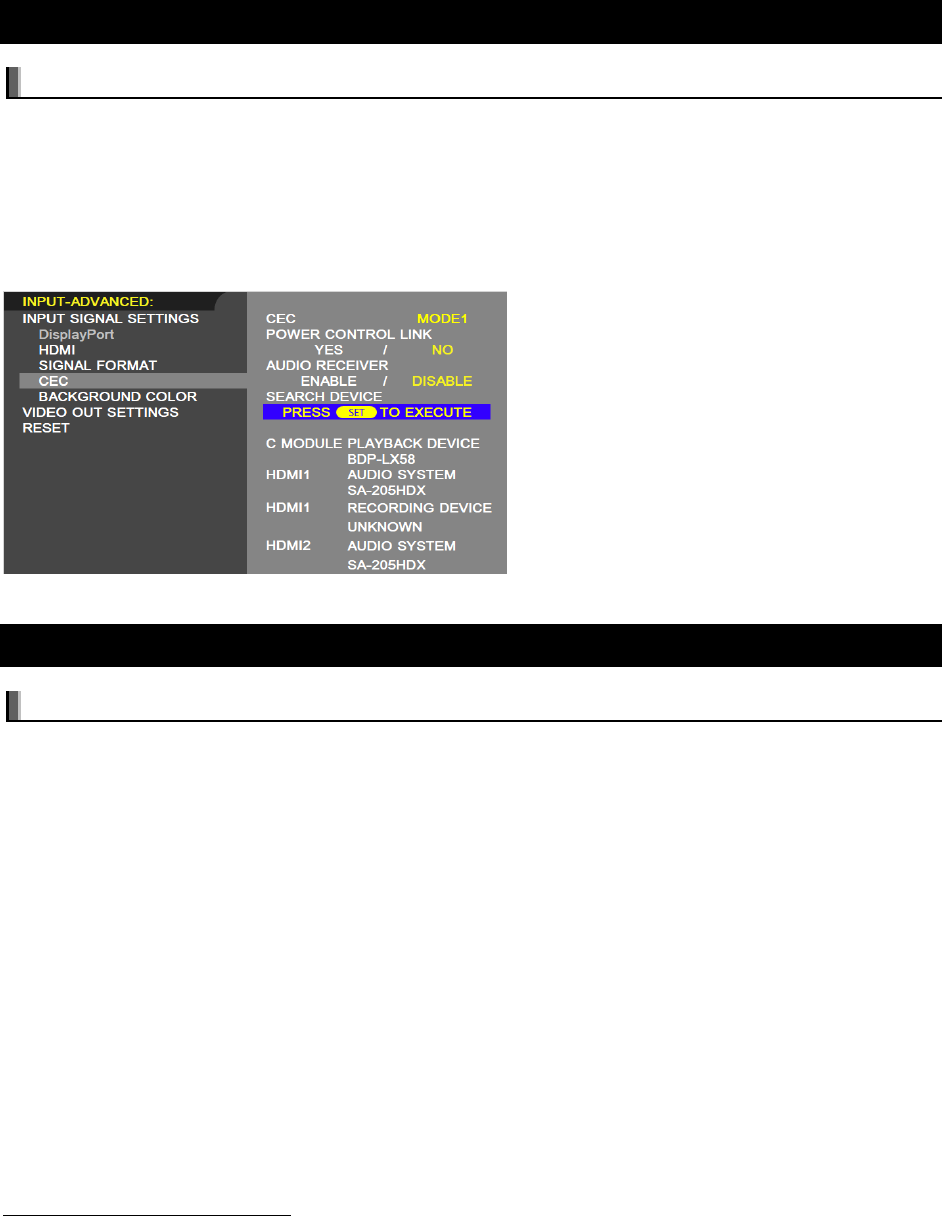
6.15 Slot Slot Power
Available options: Auto / On / Off
Allows the display to supply power to an Option Board slot during power save mode or standby mode.
AUTO and ON continuously supply power to the Option Board slot during power save and standby
modes. AUTO stops power to the Option Board slot when there is no installed device.
6.16 Input Advanced CEC CEC
Available options: Off / Mode 1 / Mode 2
Enables and disables the CEC (Consumer Electronics Control) function between the display and the
Compute Module, to control CEC enabled software via the display’s IR Remote.
• [MODE 1] – the IR Remote CEC button functions are: 1 (), 2 (), 3 (), 5 (), 6 (), ENT,
EXIT, ▲, ▼, +, –, MUTE, VOL+, VOL–.
• [MODE 2] – the IR Remote CEC button functions are: 0 to 9 and – in the keypad, ENT, EXIT, ▲,
▼, +, –, GUIDE, MUTE, SET/POINT ZOOM, VOL+, VOL–, CH/ZOOM+, CH/ZOOM–.
See section 3.4 Software control via IR Remote on page 24 for more details on using this feature.
©2021 Sharp NEC Display Solutions, Ltd. Page 51 of 86
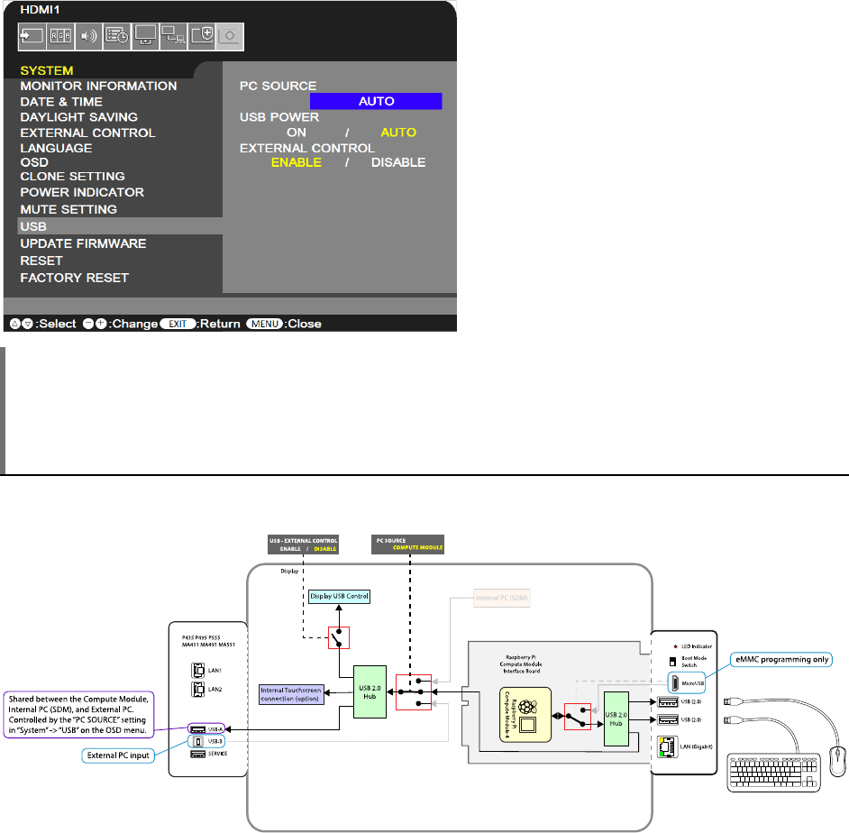
6.17 Input Advanced CEC Search Device
Available options: (SET command function only)
Pressing SET on the IR Remote will start the process of the display searching for a CEC (Consumer
Electronics Control) device on the connection to the Compute Module. If no device is found, confirm that
CEC enabled software is currently running on the Compute Module and that any CEC device drivers are
enabled.
Once the device has been detected, the display’s IR Remote can be used to navigate and control CEC
enabled software.
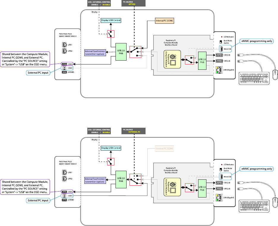
6.18 Control USB PC Source
Available options: Auto / External PC / Option / Compute Module
Selects the routing of the “USB-A” port on the display.
1
It also routes the internal USB connection from
the touch sensor on display models with an integrated touchscreen.
This setting can be switched between the Compute Module, Option (internal SDM based PC if installed),
and an External PC connected to the USB connection. By selecting AUTO, it can be configured to switch
automatically depending on the currently selected video input. This allows devices such as a mouse to be
shared automatically between different sources as the video input is changed.
For display models integrated with an optional 3
rd
party touchscreen, the internal USB connection from
the touch sensor will also follow the PC SOURCE setting so that as video inputs on the display are
changed, the touchscreen connection will automatically switch to the correct source device.
1
Current display models with a “USB-A” port on the terminal panel and PC SOURCE in the OSD menu: MA431,
MA491, MA551, P435, P495, P555
©2021 Sharp NEC Display Solutions, Ltd. Page 52 of 86
Note: A USB Type-A port, and therefore the USB PC SOURCE OSD menu setting, is only applicable
on the following display models:
MA431 P435
MA491 P495
MA551 P555
Figure 6.18-1: USB Routing with the Compute Module selected as the source
©2021 Sharp NEC Display Solutions, Ltd. Page 53 of 86
Figure 6.18-2: USB Routing with the Internal PC (SDM) selected as the source
Figure 6.18-3: USB Routing with the External PC selected as the source
©2021 Sharp NEC Display Solutions, Ltd. Page 54 of 86
7 Useful Information and Commands
7.1 To find out the IP address of the Compute Module from a terminal
window
Use the following command from a terminal window:
hostname –I
Or
ifconfig
7.2 To restart from a terminal window
Use the following command:
sudo reboot
7.3 To shutdown from a terminal window
Use the following command:
sudo shutdown -h now
7.4 To run the Raspberry Pi Config utility from a terminal window
Use the following command:
sudo raspi-config
Note: A GUI application Raspberry Pi Configuration is available from the desktop menu in the
Preferences section.
7.5 To change the keyboard layout to US from a terminal window
Run the Raspberry Pi Configuration app from the desktop menu and select the “Localization” tab to
access the keyboard settings.
Alternately use the terminal command:
sudo raspi-config
©2021 Sharp NEC Display Solutions, Ltd. Page 55 of 86
7.6 To add and remove packages from Raspberry Pi OS
To add (install) a package:
sudo apt install [packagename]
To remove (uninstall) a package:
sudo apt remove [packagename]
For more information visit:
https://www.raspberrypi.org/documentation/linux/software/apt.md
7.7 To update the Raspberry Pi
To update the current OS version:
sudo apt update
To update the current software packages installed and the kernel and firmware to the latest stable version:
sudo apt full-upgrade
Note: The Compute Module’s ‘firmware’ is stored in a file on the filesystem and can thus be
transferred if the flash memory is re-imaged to another Compute Module device.
7.8 To install the Python serial module
To install the Python serial module necessary for internal communications with the display.
From Raspberry Pi OS use:
sudo apt install python-serial
7.9 To mount a USB flash drive from the terminal
Example:
sudo mkdir /media/usbstick
sudo mount –t vfat –o uid=pi,gid=pi /dev/sda1 /media/usbstick
Replace “sda1” if drive devices is located in another location such as “sdb1”.

©2021 Sharp NEC Display Solutions, Ltd. Page 56 of 86
7.10 To access an SMB (Windows share) drive from the Raspberry Pi
OS desktop
Open a File Manger window. Enter a path into the location bar in the following format:
smb://sharename/foldername
Where “sharename” is the name of the host and “foldername” is the name of the folder being shared.
7.11 To list connected USB devices
From Raspberry Pi OS use:
lsusb
7.12 To show available disk space
From Raspberry Pi OS use:
df -h
7.13 To show internal information about the Raspberry Pi
From Raspberry Pi OS use the following to list all available commands:
vcgencmd commands
Examples:
Show the internal temperature:
vcgencmd measure_temp
Show configurations that have been set:
vcgencmd get_config int
Information about the Raspberry Pi hardware including the processor’s serial number:
cat /proc/cpuinfo
7.14 To download a file to the current directory
From Raspberry Pi OS use:
wget http://www.website.com/example.txt

©2021 Sharp NEC Display Solutions, Ltd. Page 57 of 86
7.15 To find a file by name
From Raspberry Pi OS use:
find / -name example.txt
7.16 To edit a protected system configuration file from the Raspberry
Pi OS desktop
From a terminal window open the Mousepad editor as sudo:
sudo mousepad
The file can now be opened, edited, and saved.
7.17 To prevent the screen saver from blanking the screen after
several minutes
From the Raspberry Pi OS edit the following file as sudo: /etc/lightdm/lightdm.conf
Modify the following section to add the highlighted text:
[SeatDefaults]
xserver-command=X -s 0 –dpms
7.18 Monitoring the system processes, CPU usage, and memory
The htop system tool is an interactive system-monitor process-viewer and process-manager that gives
visual information about processor, swap and memory status. Run from the command or terminal window:
htop
7.19 To enable and disable video output from the Compute Module to
the display
The internal HDMI video signal from the Compute Module to the display can be disabled and enabled
using the following commands. This can be useful for example to cause the display to enter standby
mode or switch to another video input via the loss of video from the Compute Module, depending on the
display settings.
To disable (turn off) the HDMI video signal output:
vcgencmd display_power 0
To enable (turn on) the HDMI video signal output:
©2021 Sharp NEC Display Solutions, Ltd. Page 58 of 86
vcgencmd display_power 1
7.20 To create an image of the Compute Module to backup or clone
Follow the steps to connect to a Windows host PC and place the Compute Module into BOOT MODE.
Run the Win32DiskImager software and instead of selecting Write, select Read to read the drive and
store as an .img file.
Note: Because the entire expanded system will be copied, the resulting .img file will be the size of the
flash capacity of the Compute Module
If imaging Raspberry Pi OS from a Linux machine, the image file can be reduced in size using a tool such
as PiShrink. This will reduce the time it takes to upload the image to other Compute Modules, the image
will be expanded to the full size when the Compute Module is first booted. Extreme care should be taken
to ensure that the re-expanded image is correct before distributing.
PiShrink is available on GitHub:
https://github.com/Drewsif/PiShrink
7.21 Debug GPIO lines and overlay assignments
A set of diagnostic tools for listing, monitoring, and changing the GPIO lines on the Compute Module is
available by installing the gpiod package:
sudo apt install gpiod
Six tools are available for performing various operations:
• gpiodetect
• gpioinfo
• gpioget
• gpioset
• gpiofind
• gpiomon
7.22 Assign different MAC address to the network interfaces
This section is pending.
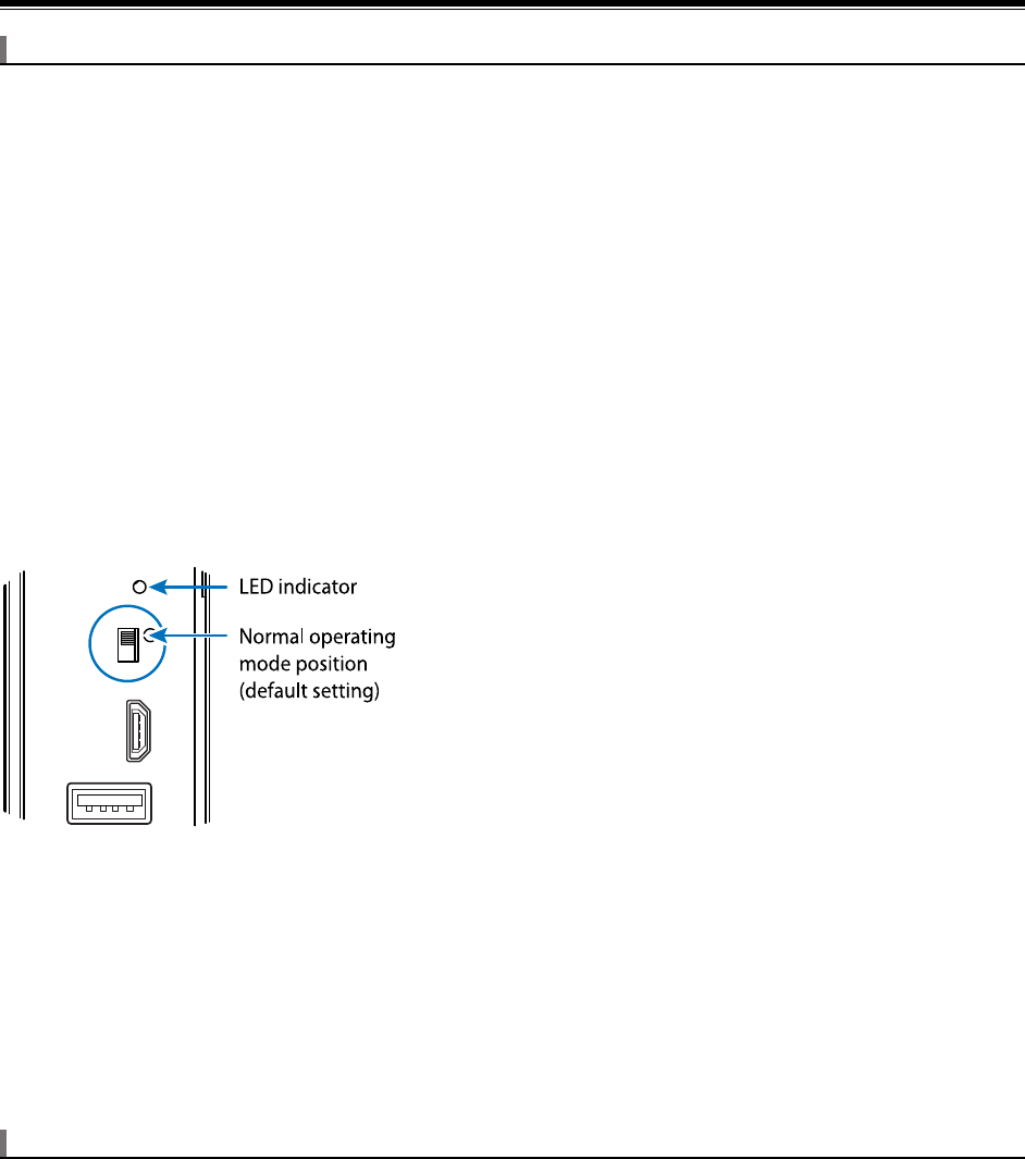
©2021 Sharp NEC Display Solutions, Ltd. Page 59 of 86
8 Troubleshooting
Problem: No video when switching to the Compute Module input
Solutions:
• Confirm that the indicator LED on the side of the Compute Module Interface Board is red or
orange. If the indicator is not on, then there is no power to the Interface Board, or the Compute
Module is not installed or not installed correctly.
• On the SLOT COMPUTE MODULE POWER CONTROL menu of the OSD, confirm
that POWER SUPPLY is set to ON.
• Check that the Compute Module 4 is correctly seated and snapped into the socket on
the Interface Board.
• Check that the BOOT MODE switch on the side of the Interface Board is in the correct position.
In normal operating mode, the switch is positioned away from the USB Micro-B connector.
Note that the postion of the switch is only recognized when power is initially applied to the
Compute Module. Changing the position of the switch after power is applied to the Compute
Module does not affect its operating/boot mode.
Figure 8-1: BOOT MODE switch - normal mode
• Confirm that a valid OS image has been written to the Compute Module.
• Confirm that the Compute Module input on the display is currently selected.
• Confirm that a valid video resolution has been configured on the Compute Module. Note that
4096x2016 @ 60Hz is currently not supported. Use the native resolution of 3840x2160 @ 60Hz
or 30Hz instead.
Problem: “RPi Boot” is unable to detect the Compute Module
If the Rpiboot window stays open and displays only “Waiting for BCM2835/6/7/2711…” then the
Compute Module has not been detected.
Solutions:
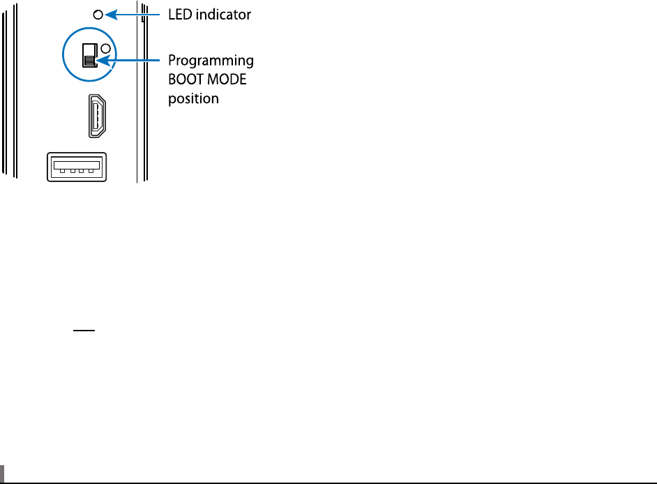
©2021 Sharp NEC Display Solutions, Ltd. Page 60 of 86
• Confirm that the indicator LED on the side of the Compute Module Interface Board is red. If the
indicator is not on, then there is no power to the Interface Board, or the Compute Module is not
installed or not installed correctly.
• On the SLOT COMPUTE MODULE POWER CONTROL menu of the OSD, confirm
that POWER SUPPLY is set to ON.
• Check that the Compute Module 4 is correctly seated and snapped into the socket on
the Interface Board.
• Check that the BOOT MODE switch on the side of the Interface Board is in the correct position.
In Programming mode, the switch is positioned towards the USB Micro-B connector.
Note that the postion of the switch is only recognized when power is initially applied to the
Compute Module. Changing the position of the switch after power is applied to the Compute
Module does not affect its operating/boot mode.
Figure 8-2: BOOT MODE switch - programming mode
• Check that a USB cable is connected from the USB Micro-B connector on the Interface Board to
the host PC.
• Check that the USB cable being used is a fully populated “data transfer” cable, and not a
“charging” cable.
• Do not use a USB extender cable or hub between the host PC and the display. The host PC must
be directly connected to the display via a single USB cable.
• “RPi Boot” may have already been run while the Compute Module has been powered up in boot
mode. Running it again will not find the Compute Module.
• Disconnect and reconnect the USB cable to the host PC.
Problem: Connected USB peripherals do not work
Solutions:
• Confirm that the USB programming cable to the USB Micro-B connector on the Interface Board
has been disconnected.
• Confirm that the onboard USB 2.0 controller has been enabled in host mode. See section 5.1
Enabling the onboard USB 2.0 controller on page 33.
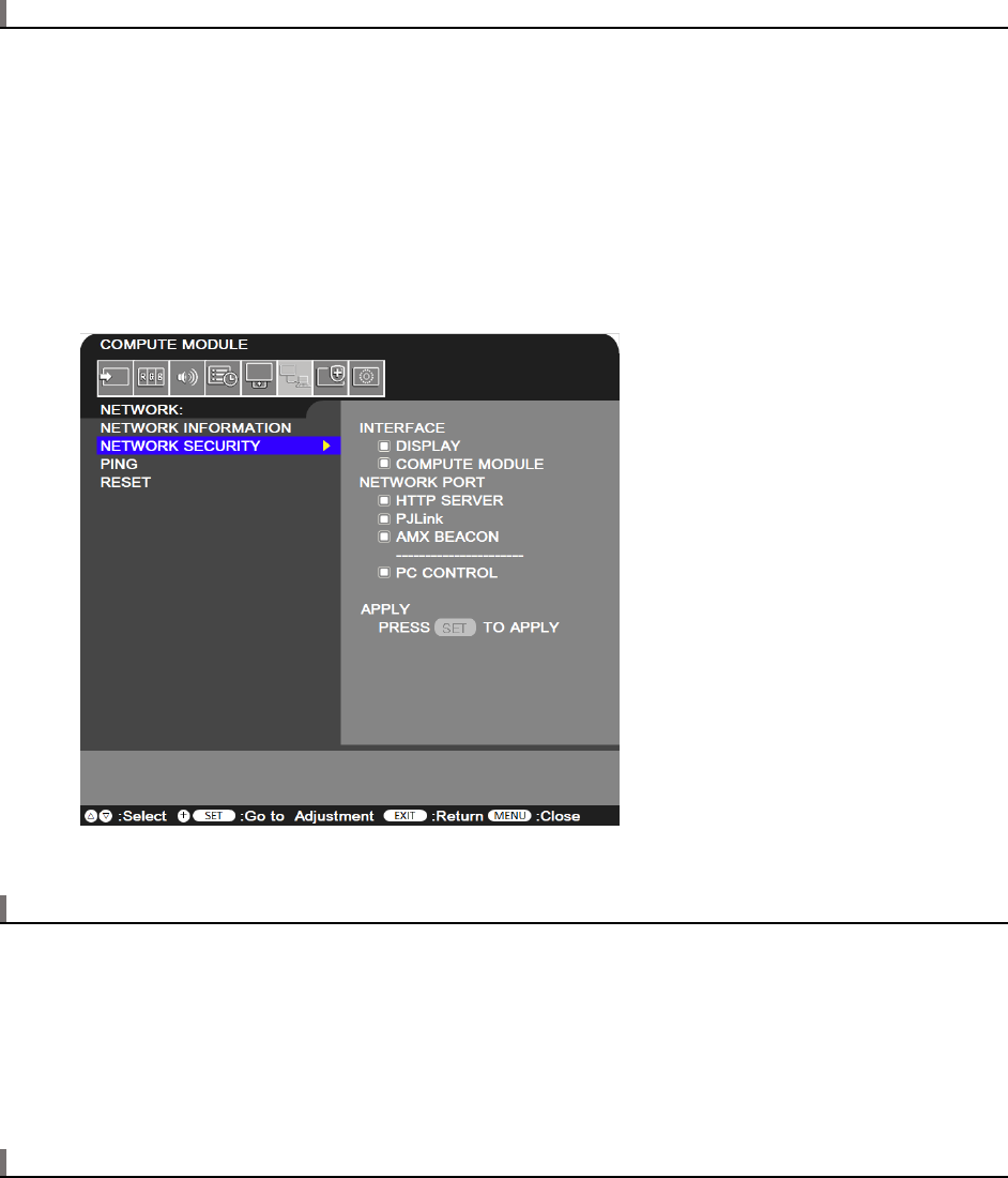
©2021 Sharp NEC Display Solutions, Ltd. Page 61 of 86
Problem: 10/100 Mbps on the display’s LAN1 and LAN2 does not work
Solutions:
• Confirm that the onboard USB 2.0 controller has been enabled in host mode. See section 5.1
Enabling the onboard USB 2.0 controller on page 33.
• Do not use this LAN interface at the same time as the Gigabit LAN connector on the Interface
Board unless specific measures have been taken to prevent the OS from assigning both
interfaces with the same MAC and IP addresses.
• Confirm that the OSD setting NETWORK NETWORK SECURITY INTERFACE COMPUTE
MODULE has been enabled.
Problem: Compute Module boots with a bootloader screen but then hangs.
Solution:
• Confirm that a valid OS image compatible with the Compute Module 4 has been written to the
Compute Module.
• Try a different application to program the Compute Module. Verify the image after writing.
Problem: Screen appears gray and blacks aren’t true black.
Solution:
• Most OS distros on the Compute Module are set to output the video range of 16 to 235
(otherwise known as “RGB limited”) by default.
©2021 Sharp NEC Display Solutions, Ltd. Page 62 of 86
• Make sure the display settings for handling the video levels from the Compute Module match
those on the OSD settings of the display. See section 5.3 Configuring the correct HDMI video
level encoding and decoding on page 33 for more details.
Problem: Black borders appear around the screen image
Solution:
• Overscan needs to be disabled. Follow the previous instructions for checking the
“
disable_overscan=1” configuration setting in the config.txt file.
Problem: 3
rd
party IR Remote is not functioning
Solutions:
• Confirm the OSD COMPUTE MODULE setting for IR SIGNAL is set to ENABLE
• Confirm lirc is enabled in the
config.txt file.
• Confirm the software being used is correctly configured for the 3
rd
party IR Remote.
• Use lirc debugging mode to view the raw IR sensor output.
• CEC support may be enabled. Normally CEC support must be disabled in order for lirc to work
correctly.
Problem: Serial communications with the display not functioning
Solutions:
• Confirm the OSD SLOT COMPUTE MODULE ADVANCED SETTING MONITOR CONTROL
setting is set to ENABLE
• Confirm the config.txt file contains the following line:
enable_uart=1
• Confirm the cmdline.txt file doesn’t contain any sections with “console=serial0…..”.
• Confirm no other software is currently accessing the serial port.
Problem: The Compute Module continually restarts
Solution:
• Confirm the OSD COMPUTE MODULE setting for WDT (Watchdog Timer) is set to DISABLE or, if
set to ENABLE, that any watchdog timer function installed is correctly configured to reset the
timer in the display within the TIME PERIOD set on the OSD.

©2021 Sharp NEC Display Solutions, Ltd. Page 63 of 86
Problem: Programming the Compute Module fails after a couple of minutes.
Solution:
• Confirm the OSD COMPUTE MODULE setting for WDT (Watchdog Timer) is set to DISABLE.

©2021 Sharp NEC Display Solutions, Ltd. Page 64 of 86
9 Video CODECs
The hardware-based video CODECs in the Compute Module 4 are enabled and licensed by default.
Please consult the official Raspberry Pi documentation for details.

©2021 Sharp NEC Display Solutions, Ltd. Page 65 of 86
10 Python Based NEC PD SDK
Sharp NEC Display Solutions has created a Python based SDK (Software Development Kit) to support
many of the display functions easily via the Operating System running on the Compute Module.
Examples of supported functions are:
• Reading status information from the display, such as:
o Model name
o Serial number
o Temperature and fan statuses
o Diagnostic information
o Operating hours
o LAN IP and MAC addresses
This makes it very easy to integrate support for remote diagnostics and asset management into
any software running on the Compute Module.
• Reading and writing almost any configuration setting and control within the display, such as:
power, video settings, schedules, Picture-in-Picture, Tile Matrix, etc.
This can be used to easily configure or reset settings via remote using a script.
• Accessing the display’s internal Real Time Clock. This can be used to set the Operating System’s
clock when it is unable to get the current time from the network.
• Monitoring the Shutdown signal from the display on GPIO 23 to gracefully shutdown any
running software and the Operating System, before the display turns off power to the Compute
Module.
• Periodically send reset commands to the display’s built in Watchdog Timer, to signal that the
Operating System is currently running correctly. The lack of a reset signal would indicate that
the CPU on the Compute Module is hung, and the display would automatically restart the
Compute Module.
Communications with the display is via the UART on the Compute Module and an internal serial
connection to the display. It is also possible to communicate with the display over LAN via its IP address.
The SDK supports communicating via both serial and LAN.
The SDK provides APIs (Application Programming Interfaces) for most of the commands supported by
the display, so it is not necessary to start understanding the communications protocol from scratch.
However, it is highly recommended to refer to the “External Control” document for the model being used
to understand the parameters and function of each API.
The SDK can be installed from Raspberry Pi OS using either of the following commands:
sudo easy_install nec_pd_sdk
or
sudo –H pip install nec_pd_sdk
It can also be downloaded or cloned from the repository on GitHub:

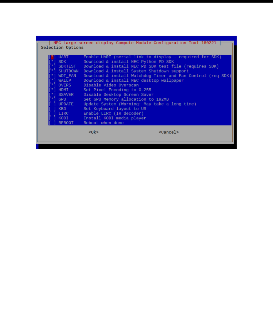
©2021 Sharp NEC Display Solutions, Ltd. Page 67 of 86
11 Compute Module Configuration Tool for
Raspberry Pi OS
Sharp NEC Display Solutions has created a menu-based tool for automatically downloading and
configuring various components and settings for Raspberry Pi OS on the Raspberry Pi Compute Module.
This makes it easy to configure a new OS install.
Options include:
• Configuring the UART to allow communications with the host display.
• Downloading and installing the NEC Python PD SDK which provides APIs for communicating with
the host display. It will also install the Python Serial module if necessary.
• Downloading and installing an example Python file showing how to use the SDK APIs to
communicate with the host display.
• Downloading and installing a Python file that provides System Shutdown support by monitoring
GPIO 23 - set low by the display to signal a shutdown.
• Downloading and installing a Python file that provides hardware-based Watchdog Timer support.
• Downloading and installing NEC branded desktop wallpaper.
• Disabling Video Overscan.
• Setting the HDMI Pixel (video level range) Encoding to 0-255.
• Disabling the Desktop Screen Saver to prevent screen blanking.
• Setting the GPU Memory allocation to 192MB.
• Updating the operating system and firmware.
• Setting the Keyboard layout to "US".
• Enabling the LIRC (IR decoder) support.
• Installing the KODI media player with remote control using the display's IR Remote.
• Installing the Yodeck bootloader. This item is not compatible with the Compute Module 4.
This can be downloaded from:

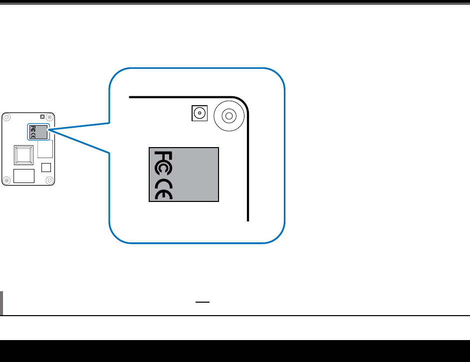
©2021 Sharp NEC Display Solutions, Ltd. Page 69 of 86
12 Wireless connectivity installation and
configuration
This section is relevant only when using the DS1-IF21CE interface board together with a version of the
Compute Module 4 that has built-in wireless functionality. A wireless enabled Compute Module can easily
be identified by the silver-colored metal enclosure with engraved FCC and CE logos on the module.
Figure 12-1 Compute Module 4 with wireless functionality
The model of Interface Board is printed on the underside of the board.
Note: The DS1-IF20CE interface board is not certified for wireless operation and the Wi-Fi and
Bluetooth functions are disabled at the hardware level.
12.1 Important cautions
• The Compute Module, DS1-IF21CE interface board, and display are certified for use only with
the antenna provided in the kit. Using a different type of antenna will invalidate these
certifications and may be a violation of laws designed to prevent radio interference.
• Failure to correctly route the antenna coax and connectors as shown in this document may
cause unwanted interference and degraded performance. Please carefully follow the
instructions provided when installing the antenna components.
• The Compute Module, DS1-IF21CE interface board, and display are certified for use only in
certain countries and geographic regions. Use outside these areas may be in violation of local
laws.
• The U.FL type connectors are designed for a limited number of connections and disconnections.
Avoid repeated disconnections as much as possible.
• Do not make sharp bends or kinks to the antenna coax cable.
• Do not operate the wireless functions without the coax cable and external antenna attached to
the Compute Module.
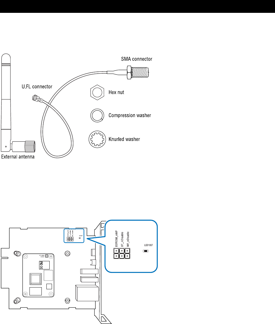
©2021 Sharp NEC Display Solutions, Ltd. Page 70 of 86
12.2 Parts identification
• External antenna with SMA female connector.
• Coax cable with SMA male connector and U.FL connector.
• Hex nut, knurled washer, and compression washer.
Figure 12.2-1 Antenna parts
• U.FL antenna connector on the Compute Module
• WF_nDisable wireless function header pins
• EEPEOM_nWP header pins
• LED1007 Wi-Fi enable LED status indicator
Figure 12.2-2 Compute Module and Interface Board
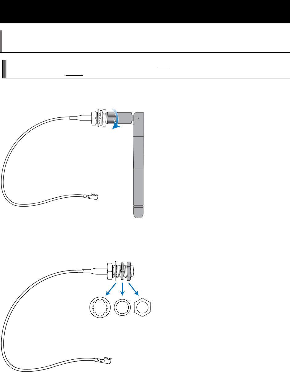
©2021 Sharp NEC Display Solutions, Ltd. Page 71 of 86
12.3 Installing the antenna connector to the Compute Module and
routing the coax cable
Note: Depending on the configuration purchased, these steps will typically already have been
performed by NEC and the antenna connectors will have been pre-installed. These steps are being
provided for reference in case the Compute Module or Interface Board is swapped.
Important: The antenna coax cable must be installed after the Compute Module is installed onto the
Interface Board, but before the heatsink is installed.
1. Unscrew the antenna from the SMA type external antenna connector on the coax cable
and set aside.
Figure 12.3-1 Remove external antenna
2. Unscrew the hex nut from the external antenna connector and remove the two washers
and set aside.
Figure 12.3-2 Remove hex nut and washers
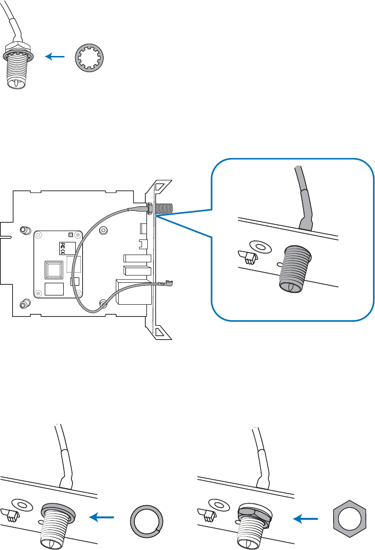
©2021 Sharp NEC Display Solutions, Ltd. Page 72 of 86
3. Visually inspect the antenna coax cable and connectors for damage such as kinks or bent
connectors. Do not attempt to install the cable and connectors if there is any damage.
4. Put the knurled washer on the SMA type external antenna connector.
Figure 12.3-3 Place knurled washer on external antenna connector
5. Push the antenna connector through the mounting hole on the bracket of the interface
board from the board side.
Figure 12.3-4 Insert antenna connector through Interface Board bracket
6. Put the compression washer and hex nut on the antenna connector from the external
side of the bracket. Hand-tighten the hex nut and tighten further using an 8mm hex
wrench or similar tool. Do not overtighten.
Figure 12.3-5 Place compression washer and hex nut
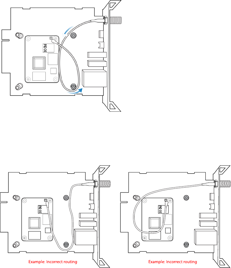
©2021 Sharp NEC Display Solutions, Ltd. Page 73 of 86
7. Route the antenna coax cable as shown in the illustration. It should be routed around
the mounting post as shown.
Figure 12.3-6 Correct routing of the antenna coax cable
Note: Do not make sharp bends or kinks to the coax cable, and do not route the cable
across the Compute Module so that it is between the heatsink and Compute Module
after the heatsink is installed.
Figure 12.3-7 Examples of incorrect routing of the antenna coax cable
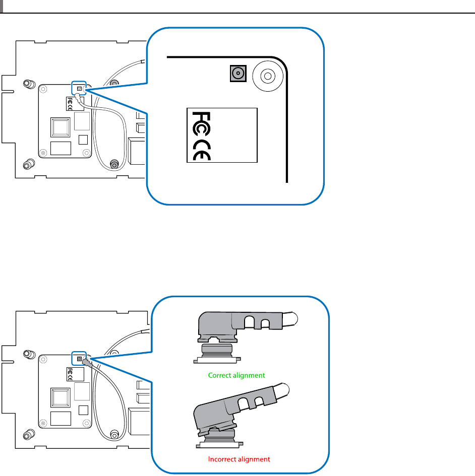
©2021 Sharp NEC Display Solutions, Ltd. Page 74 of 86
8. Locate the U.FL antenna receptacle connector on the Compute Module near the silver
wireless module with the FCC and CE engraving.
Note: If needed, the FCC / ISED ID of the Compute Module is engraved onto the wireless module.
Figure 12.3-8 U.FL antenna receptacle connector on the Compute Module
9. Carefully align the antenna cable connector over the antenna receptacle connector on
the Compute Module, with the coax cable routed over the corner of the Compute
Module as shown.
Figure 12.3-9 U.FL antenna connector alignment of receptacle and cable
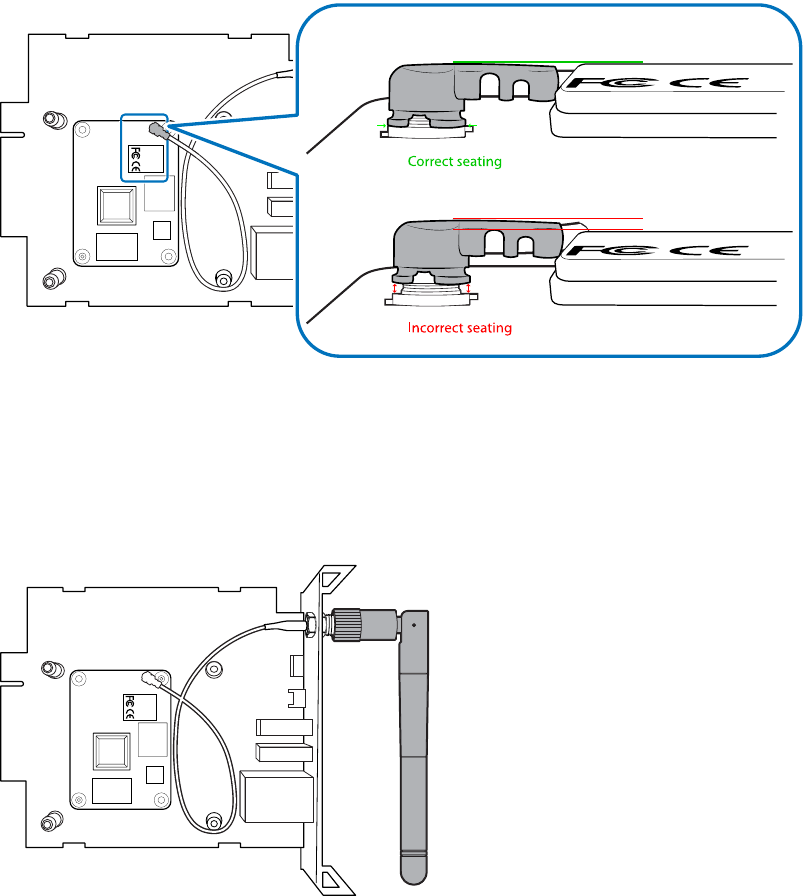
©2021 Sharp NEC Display Solutions, Ltd. Page 75 of 86
10. When in position, push the U.FL connector down onto the receptacle until it snaps into
place and is correctly seated. The top of the connector should be parallel to and at the
same height as the silver wireless module on the Compute Module. If the connector
does not snap into place, carefully inspect both sides for any damage and try again.
Figure 12.3-10 U.FL antenna connector seating on the Compute Module
11. Carefully inspect the antenna connectors and coax cable before proceeding to install the
heat-sink. Confirm that the coax cable is routed correctly and will not be pinched by the
heatsink and avoids being caught in the heatsink posts.
12. When the entire assembly is complete attach the external antenna to the bracket.
Figure 12.3-11 Attach external antenna
13. Proceed with installing the heatsink. See Section 2 on page 15

©2021 Sharp NEC Display Solutions, Ltd. Page 76 of 86
12.4 Enabling and disabling Wi-Fi at the hardware level
The Wi-Fi functionality of the Compute Module can be disabled at the hardware level by installing a
header jumper across the pins on the Interface Board labeled WF_nDisable. Disabling at the hardware
level overrides enabling Wi-Fi at the software level.
Do not jumper the header pins if the Wi-Fi functionality will be used. Note that Wi-Fi must also be enabled
at the software level, as well as selecting the external antenna. See the next section for details.
Use the raspi-config tool in Raspberry Pi OS to configure the wireless functions at the software level.
There is a green diagnostic LED located on the Interface Board labeled LED1007 that will illuminate when
the Wi-Fi module is enabled at the hardware level. This LED will be visible through the ventilation holes
on the back of the display when the board is installed.
12.5 Selecting the external antenna in software
The Compute Module 4 has a software defined antenna selection to select between the onboard antenna
and an external antenna connected via the U.FL connector.
The onboard antenna will be covered by the heat-sink and enclosed within the metal case of the display
and the signal will not radiate. Therefore, the external antenna must be selected in software.
To select the external antenna, edit the config.txt file in the boot folder/partition and edit or add the
following line:
dtparam=ant2
Make sure that there is not also a line in the file selecting the internal antenna ( dtparam=ant1 ).
12.6 Bluetooth functionality
At the time of writing, Bluetooth functionality is not yet certified for operation.
12.7 Troubleshooting wireless functionality
Problem: Operating system does not detect the Wi-Fi module
Solution:
• Check that the interface board type is the DS1-IF21CE type with wireless functionality enabled.
The type DS1-IF20CE interface board does not support wireless functionality.
• Check that a header jumper has not been installed across the pins on the Interface Board
labeled
WF_nDisable.
• Check if the green diagnostic LED located on the Interface Board labeled
LED1007 is illuminated,
indicating that the Wi-Fi module is enabled at the hardware level. This LED will be visible
through the ventilation holes on the back of the display when the board is installed.

©2021 Sharp NEC Display Solutions, Ltd. Page 77 of 86
• Confirm that the Wi-Fi drivers are available and have been enabled in the operating system
being used. Raspberry Pi OS normally includes these drivers, but the Wi-Fi functionality must be
manually configured and enabled.
Problem: Poor or no Wi-Fi signal but Wi-Fi is enabled
Solution:
• Confirm that the external antenna is selected in software see Section 12.4 on page 76.
• Confirm the external antenna is correctly connected to the SMA type socket on the bracket of
the Interface Board.
• Check the internal coax cable for kinks or other damage.
• Confirm that the U.FL connector on the coax cable is correctly connected to the U.FL antenna
receptacle on the Compute Module.
• Check for sources of external interference.

©2021 Sharp NEC Display Solutions, Ltd. Page 78 of 86
13 External reference information
Main Raspberry Pi website:
https://www.raspberrypi.org/
Wikipedia page with listing of other supported operating systems:
https://en.wikipedia.org/wiki/Raspberry_Pi#Operating_systems
Another listing of Raspberry Pi based operating system distributions:
http://elinux.org/RPi_Distributions
Information for programming the Compute Module and updating the bootloader:
https://www.raspberrypi.org/documentation/hardware/computemodule/cm-emmc-flashing.md
Official specification of the Compute Module 4:
http://datasheets.raspberrypi.org/cm4/cm4-datasheet.pdf
Information on using raspi-config:
https://www.raspberrypi.org/documentation/configuration/raspi-config.md
Information on configuring boot overlays:
https://github.com/raspberrypi/firmware/blob/master/boot/overlays/README
Information configuring and uploading the bootloader:
https://github.com/raspberrypi/rpi-eeprom
Information on using VNC to remotely control the desktop interface from another machine:
https://www.raspberrypi.org/documentation/remote-access/vnc/README.md


©2021 Sharp NEC Display Solutions, Ltd. Page 80 of 86
14 Frequently Asked Questions
What video resolutions are recommended and supported?
Using the display’s native resolution of 3840x2160 is recommended. Other resolutions such as
1920x1080 can also be used.
The following video resolutions do not currently display correctly and should be avoided:
• 4096x2160 @ 60Hz (use the native 3840x2160 @ 60Hz instead)
• 1920x2160 @ 60Hz
Can the second HDMI output or camera inputs on the Compute Module 4 be accessed from the
Interface Board?
No. These connections are not exposed on the Interface Board.
Is the Raspberry Pi Compute Module functionality limited in some way, such as what software or
Operating Systems can be used?
No.
Are the GPIO pins on the Compute Module accessible and open to use?
Currently the header on the NEC Compute Module Interface Board is not populated with header pins and
is not officially supported. Some GPIO pins are used for display related functions as described elsewhere
in this document.
What is the communications speed of the internal serial connection to the display?
9600 baud. No parity. 8 bits data length with 1 stop bit.
Does Sharp NEC Display Solutions provide support for any software or Operating System on the
Compute Module?
Sharp NEC Display Solutions provides a Python based SDK for accessing the display control functionality
via the internal serial connection. Support for other software or Operating Systems are not provided by
Sharp NEC Display Solutions. See Python Based NEC PD SDK on page 65.

©2021 Sharp NEC Display Solutions, Ltd. Page 81 of 86
Does the NEC Compute Module Interface Board provide SD card support to use instead of the
onboard eMMC memory?
No.
Can the video output of the Compute Module be daisy-chained to another display via the
DisplayPort Output connection?
No. Some display models can output to the HDMI Output. See below.
Can the video output of the Compute Module be daisy-chained to another display via the HDMI
Output connection?
Yes. The video output of the Compute Module can be output on the HDMI OUT connector and daisy-
chained to another display on the following display models:
o MA431
o MA491
o
MA551
o P435
o P495
o
P555
Note that at this time, copyright-protected content cannot output on the display’s HDMI Output connection
as the Compute Module 4 does not currently support HDCP.
The following display models do not support this feature:
o M431
o M491
o M551
o
M651
o ME431
o ME501
o ME551
o
ME651
Is it possible to run Android OS on the Compute Module?
There are currently some experimental builds of Android for the Raspberry Pi; however, these are
probably not stable enough to be used for professional and commercial applications and may not even
work on the Compute Module version of the Raspberry Pi.
Does the Compute Module 4 provide support for Wi-Fi or Bluetooth?
Versions of the Compute Module with built-in wireless functionality together with the DS1-IF21CE
interface board can be used to provide Wi-Fi using an external antenna. At the time of writing the
Bluetooth function is disabled by the Interface Board pending regulatory approvals.
©2021 Sharp NEC Display Solutions, Ltd. Page 82 of 86
Is it possible to boot directly to an external USB drive instead of the onboard eMMC memory?
Yes. The Compute Module 4 Bootloader can be modified to change the boot order to directly boot from a
USB drive. Details of configuring and uploading the bootloader are available from Raspberry Pi:
https://github.com/raspberrypi/rpi-eeprom
Note that the EEPROM of the Compute Module can be write protected to prevent the bootloader from
being updated by installing a jumper across the EEPEOM_nWP pins on the Interface Board.
What is the LAN MAC address of the Compute Module?
The LAN MAC address is assigned by the Compute Module itself and is derived from the CPU serial
number.
The first 3 octets (B8:27:EB) are fixed and assigned to Raspberry Pi Foundation. The remaining 3 octets
are the last 6 hex digits of the CPU serial number. For example, if the CPU serial number is
0000000096bf4e08 the MAC address will be B8:27:EB:BF:4E:08. The CPU serial number can be
obtained by using:
cat /proc/cpuinfo
Note that both the Gigabit and 10/100 Mbps LAN interfaces will be assigned a MAC address based on
the serial number of the Compute Module. At the time of writing, Raspberry Pi OS will assign identical
MAC and IP addresses to both interfaces. This will lead to an illegal ethernet condition if both network
ports are connected to the same network and may result in degraded or no network connectivity.
What is the Wi-Fi MAC address of the Compute Module?
On Raspberry Pi OS, the Wi-Fi MAC address is derived similarly to the LAN MAC address, except the
bottom 48 bits of the CPU serial number is XOR'd with 0x555555 to avoid colliding with the LAN MAC
address. Other operating systems may assign the MAC address differently.
How long does it take to program the Compute Module?
It depends on the size of the image being programmed. USB read and write speeds are typically 5MB/s.
So, a 4GB image will take approximately 13 minutes to write. That time will double if verification is used.
How can I find out the LAN IP or MAC address of the host display from the Compute Module?
The Python SDK includes the functions command_ip_address_read() and
command_lan_mac_address_read() that will return the IP and MAC address of the display if it has
been configured with a static IP address.

©2021 Sharp NEC Display Solutions, Ltd. Page 83 of 86
How can the Compute Module be automatically shut down when the display is turned off?
Power settings for the Compute Module are managed in the display's OSD SLOT menu. The auto
shutdown control in that menu will enable performing a shutdown of the Compute Module when the
display is turned off via a command, power button, OSD menu, or IR Remote. See Auto Shutdown in
section 6.5 on page 45.
Are the NEC displays compatible with the Compute Module 4 Lite?
No. The CM Lite requires SD card support.

©2021 Sharp NEC Display Solutions, Ltd. Page 84 of 86
15 Known Issues
Display Firmware
• No known issues
Video Related
• The following video resolutions do not currently display correctly and should be avoided:
• 4096x2160 @ 60Hz (use the native 3840x2160 @ 60Hz instead)
• 1920x2160 @ 60Hz

©2021 Sharp NEC Display Solutions, Ltd. Page 85 of 86
16 Support
For more general support on the Raspberry Pi, Raspberry Pi OS, and the Compute Module, it is
recommended to visit the support forums at the Raspberry Pi Foundation:
https://www.raspberrypi.org/forums/
The latest version of this document, additional information, downloads, and feedback forms specifically
relating to using the Raspberry Pi Compute Module together with a supported NEC display model are
available here:
https://www.sharpnecdisplays.us/support-and-services/raspberrypi/244
The latest display firmware is available from the following location:
https://www.sharp-nec-displays.com/dl/en/dp_soft/pd_fm_update/index.html

©2021 Sharp NEC Display Solutions, Ltd. Page 86 of 86
17 Disclaimer
Failure to correctly install the wireless related components as described in this document may cause
unwanted interference and degraded performance. Please carefully follow the instructions provided when
installing the antenna components to ensure compliance with local EMC laws and regulations. No
responsibility is assumed for non-compliance related to incorrect installation.
