
NEC Large-Screen Displays
Raspberry Pi Compute Module
Setup Guide
Revision: 190307

©2019 NEC Display Solutions, Ltd. Page 2 of 74
Introduction
This document describes the features, installation, connectivity, and configuration of the Raspberry Pi
Compute Module support in NEC Large-Screen display models. Please see “Requirements” on page 9 for
a current list of supported displays and Raspberry Pi hardware.
Notes:
1. The acts of disclosure, duplication, and modification of part or whole contents in this reference
manual without permission are prohibited.
2. The contents of this reference manual are subject to change without notice.
3. Great care has been taken in the preparation of this reference manual; however, should you
notice any questionable points, errors or omissions, please contact us.
Copyright and Trademarks
Copyright © 2019 NEC Display Solutions, Ltd.
The content of this manual is furnished for informational use only, is subject to change without notice,
and should not be construed as a commitment by NEC Display Solutions, Ltd. NEC Display Solutions,
Ltd. assumes no responsibility or liability for any errors or inaccuracies that may appear in this manual.
Windows® is a registered trademark of Microsoft Corporation.
NEC is a registered trademark of NEC Corporation.
Linux® is the registered trademark of Linus Torvalds in the U.S. and other countries.
Raspberry Pi is a trademark of the Raspberry Pi Foundation.
Ubuntu is a registered trademark of Canonical Ltd.

©2019 NEC Display Solutions, Ltd. Page 3 of 74
Contents
Introduction .............................................................................................................................. 2
Contents ................................................................................................................................... 3
Revision History ....................................................................................................................... 6
Basic Features ......................................................................................................................... 7
GPIO Summary ......................................................................................................................... 9
Requirements ........................................................................................................................... 9
Operating System Programming Procedure .......................................................................... 9
1 Basic Setup and Configuration Steps ..............................................................................11
2 Installing the Compute Module and NEC Compute Module Interface Board to the
Display ...............................................................................................................................12
3 Connections and Internal Operation ................................................................................15
3.1 USB device connections to the Compute Module ...................................................................... 15
3.2 USB connections for programming the Compute Module ......................................................... 16
3.3 LAN connections ......................................................................................................................... 17
3.4 Software control via IR Remote .................................................................................................. 18
4 Preparation ........................................................................................................................22
5 Operating System Summary ............................................................................................23
6 Preparing and Running the Tools to Make the Compute Module Appear as a Mass
Storage Device ..................................................................................................................26
6.1 Using a Windows PC as a host .................................................................................................... 26
6.2 Using a Raspberry Pi 1, 2, or 3 as a host ..................................................................................... 29
7 Using the Yodeck bootloader to overwrite the current OS ............................................33
8 Miscellaneous Configuration Items .................................................................................34
8.1 Configuring the correct HDMI video level encoding and decoding ............................................ 34
8.2 To disable overscan (if black bars are visible on the sides of the screen) .................................. 35
8.3 To rotate the screen image to portrait orientation .................................................................... 36
8.4 To enable support for the IR Remote receiver using “lirc” ......................................................... 36
8.5 To test support for the IR Receiver by outputting raw data ....................................................... 37
8.6 Enabling the serial port (UART) to the display and allowing application access ........................ 38
8.7 Testing internal serial communications to the display using the Python based NEC PD SDK .... 39
8.8 Configuring the Compute Module to shutdown using shutdown signal from the display ......... 40
©2019 NEC Display Solutions, Ltd. Page 4 of 74
8.9 Creating an image of the Compute Module to backup or clone ................................................ 41
8.10 Reading and setting the display’s internal Real Time Clock (RTC) from the OS ......................... 41
8.11 Using the display’s Watchdog Timer (WDT) ............................................................................... 41
8.12 Controlling the Compute Module cooling fan ............................................................................ 43
8.13 Controlling the Compute Module power .................................................................................... 43
8.14 Checking and updating the display firmware version ................................................................. 43
9 Related OSD Settings .......................................................................................................45
9.1 Compute Module menu Power Power Supply .................................................................. 45
9.2 Compute Module menu Power Auto Power On ............................................................... 45
9.3 Compute Module menu Service Menu Setting Lock ......................................................... 45
9.4 Compute Module menu Service Menu USB Boot Mode ................................................... 46
9.5 Compute Module menu Service Menu IR Signal ............................................................... 46
9.6 Compute Module menu Service Menu Monitor Control .................................................. 46
9.7 Compute Module menu Service Menu Shutdown Signal ................................................. 47
9.8 Compute Module menu Service Menu Shutdown Signal Power Supply Off Delay ...... 47
9.9 Compute Module menu Service Menu WDT .................................................................... 47
9.10 Compute Module menu Service Menu WDT Start Up Time ........................................ 48
9.11 Compute Module menu Service Menu WDT Period Time ........................................... 48
9.12 Control menu USB External Control
.................................................................................. 49
9.13 Control menu USB PC Source ............................................................................................ 49
9.14 Control menu USB USB Power .......................................................................................... 51
9.15 Control menu CEC CEC ...................................................................................................... 52
9.16 Control menu CEC Search Device ...................................................................................... 52
9.17 Expert menu Compute Module CM Fan Power ................................................................ 53
9.18 Expert menu Compute Module CM Auto Shutdown ........................................................ 53
10 Useful Information and Commands .................................................................................55
10.1.1 To find out the IP address of the Compute Module from a terminal window ................... 55
10.1.2 To restart from a terminal window ..................................................................................... 55
10.1.3 To shutdown from a terminal window ............................................................................... 55
10.1.4 To run the Raspberry Pi Config utility from a terminal window ......................................... 55
10.1.5 To change the keyboard layout to US from a terminal window ......................................... 55
10.1.6 To add and remove packages from Raspbian ..................................................................... 56
©2019 NEC Display Solutions, Ltd. Page 5 of 74
10.1.7 To update the Raspberry Pi ................................................................................................. 56
10.1.8 To install the Python serial module .................................................................................... 57
10.1.9 To mount a USB flash drive from the terminal ................................................................... 57
10.1.10 To access an SMB (Windows share) drive from the Raspbian desktop .......................... 57
10.1.11 To list connected USB devices......................................................................................... 57
10.1.12 To show available disk space .......................................................................................... 57
10.1.13 To show internal information about the Raspberry Pi ................................................... 58
10.1.14 To download a file to the current directory .................................................................... 58
10.1.15 To find a file by name ...................................................................................................... 58
10.1.16 To edit a protected system configuration file from the Raspbian desktop .................... 58
10.1.17 To install a minimal windowing system on Jessie Lite .................................................... 58
10.1.18 To prevent the screen saver from blanking the screen after several minutes ............... 59
10.1.19 To enable IR Remote control using CEC from OSMC ...................................................... 59
10.1.20 To enable IR Remote control using lirc from OSMC ....................................................... 59
10.1.21 Monitoring the system processes, CPU usage, and memory ......................................... 59
10.1.22 To enable and disable video output from the Compute Module to the display ............ 60
11 Troubleshooting ................................................................................................................61
12 Codec Licenses .................................................................................................................64
13 Python Based NEC PD SDK .............................................................................................65
14 Compute Module Configuration Tool for Raspbian ........................................................67
15 External reference information.........................................................................................69
16 Frequently Asked Questions ............................................................................................70
17 Known Issues ....................................................................................................................73
18 Support
..............................................................................................................................74

©2019 NEC Display Solutions, Ltd. Page 6 of 74
Revision History
Revision
Date
Modified by
Description
170327
March 27, 2017
Will Hollingworth
First public release
170410
April 10, 2017
Rebecca Holz
OSD screens inserted in chapters 6, 7, 8
Update Requirements
Add Wi-Fi FAQ
170606
June 06, 2017
Will Hollingworth
Added to FAQs, Troubleshooting, and
Support sections
Added hyperlinks to OS distros in chapter 5
Add illustrations from final product guide
170810
August 10, 2017
Will Hollingworth
Added to FAQs and Troubleshooting sections
Updated OS distros
Added chapter on Configuration Tool for
Raspbian
Added etcher.io as alternate flash tool.
171129
November 29, 2017
Will Hollingworth
Updated download location of the Windows
Compute Module boot installer.
180222
February 22, 2018
Will Hollingworth
Added CM Fan Power and CM Auto
Shutdown controls. Added FAQ about reading
IP and MAC of the display.
180701
July 1, 2018
Will Hollingworth
Added new display models. Minor corrections
and updates.
180829
August 29, 2018
Rebecca Holz
Fix typo in product model number
190307
March 7, 2019
Will Hollingworth
Added new display models, Yodeck
bootloader, CM3+, FAQs.

©2019 NEC Display Solutions, Ltd. Page 7 of 74
Basic Features
• Operating System support
o Select from many publicly available OS distributions and images depending on the
application, such as: fully featured and ready to use networked media players, kiosk
interfaces, full desktop based operating systems, and minimal systems.
• Internal LAN switch
o The Raspberry Pi Compute Module features LAN connectivity via the display’s internal
LAN switch. It is a separate LAN device from the internal media player and the display’s
LAN control interface. The Compute Module will have its own IP address and network
settings. Two of the switch ports are available externally for daisy-chaining other devices.
o LAN1 port should be used to connect to the network. The LAN2 output can be used to
connect other LAN devices or displays.
• USB hub with up to 3 ports for connecting devices
o USB devices, such as keyboards, mice, and Wi-Fi adapters, can be connected without the
need for an external USB hub.
o Use the USB CM1 and CM2 connectors for devices dedicated to the Compute Module.
The CM1 connector is capable of supplying up to 2A of power.
o The USB1 connector can be configured for connecting an additional USB device to the
Compute Module, an optional internal PC (OPS), or an external PC. This can be set to
switch automatically, depending on the currently selected video input, or fixed to a
specific source.
• Internal IR remote receiver and pass through to the Raspberry Pi Compute Module
o The display's IR Remote Control can be used to operate software running on the
Raspberry Pi Compute Module, such as a media player, via standard IR Remote Control
units. The Remote Control communicates to the Compute Module via the display's
internal Remote Control sensor or external KT-RC2 sensor. It will be necessary to
configure such software with the IR codes for the remote control units being used.
o This uses GPIO 18 on the Raspberry Pi.
• CEC support between the display and the Raspberry Pi Compute Module
o Facilitates the use of the display’s IR Remote buttons to control the basic navigation
functions of compatible software, such as media players.
• Internal serial connection between the display and the Raspberry Pi Compute Module
o Allows full control and monitoring of the display from the Compute Module.
o This uses GPIO 14 & 15 (UART0) on the Raspberry Pi Compute Module.
o A Python based SDK is available from NEC for easy software development. See Python
Based NEC PD SDK on page 65.
• Real Time Clock support via the display’s internal clock
o The display’s internal Real Time Clock can be read and set via the Compute Module,
using the internal serial connection and the Python based SDK.
o This can be used to set the system time when no network connection is available.

©2019 NEC Display Solutions, Ltd. Page 8 of 74
• Shutdown signal support
o The display can signal to the Operating System, running on the Raspberry Pi Compute
Module, that the power is about to turn off so the software and OS can shutdown
gracefully.
o This uses GPIO 23 on the Raspberry Pi Compute Module.
• Full power control
o Power for the Compute Module can be configured to automatically turn on when the
display is turned on from a standby mode, or it can be turned on separately via the
display’s OSD, HTTP interface, or network commands.
o By default, the Compute Module will remain powered on even when the display goes
into standby mode and can be turned off separately via the display’s OSD, HTTP
interface, or network commands.
The display can be configured to turn off the Compute Module power with the display
power.
1
o By default, the fan on the NEC Compute Module Interface board will remain on
whenever the Compute Module is powered.
The fan operation can be controlled via the OSD or commands from the Compute
Module.
1
• Watchdog timer support
o Can be used to reset a locked CPU by automatically restarting the Compute Module. A
restart will occur if no periodic reset signal is received from the Compute Module within
a certain time period.
• Hardware codec support licenses
o The Raspberry Pi Compute Module 3 NEC edition includes hardware codec licenses for
MPEG-2, MPEG-4, and VC-1.
• Built in touch-screen support
o For display models with integrated touch-screens, the USB touch device will appear as a
standard USB HID (Human Interface Device) device to the Compute Module.
1
These models require display firmware version R1.7 or later for this feature: P404, P484, P554, V404, V484, V554,
V404-T, V484-T, V554-T

©2019 NEC Display Solutions, Ltd. Page 9 of 74
GPIO Summary
• GPIO 14 & 15 (UART0 TX & RX) – internal serial connection to the display
• GPIO 18 – demodulated IR receiver from the display
• GPIO 23 – shutdown signal (goes low to signal shutdown)
Requirements
• Compatible NEC display
o C751Q
o C861Q
o C981Q
o P404
o P484
o P554
o P654Q
o P754Q
o V404
o V404-T
o V484
o V484-T
o V554
o V554-T
o V554Q
o V654Q
o V754Q
o V864Q
o V984Q
o UN462A
o UN462VA
o UN492S
o UN492VS
o UN552
o UN552A
o UN552S
o UN552V
o UN552VS
o UX552
o UX552S
• NEC Compute Module Interface board
o DS1-IF10CE
• Raspberry Pi Compute Module
o CM3 16 GB NEC Edition – (RPi3CM16G)
o CM1 or CM3 4 GB from RaspberryPi
o
CM3+ 8, 16, or 32 GB versions from RaspberryPi
• Internet connection
• LAN hub and cables
• Standard USB 2.0 cable
• Host PC running either Windows or Ubuntu, or a standard Raspberry Pi 1 / 2 / 3 running
Raspbian OS
• USB keyboard and mouse for connecting to the display (recommended)
• Operating system
.img file
• Software configuration tools (see following sections)
Operating System Programming Procedure
The custom 16GB Raspberry Pi Compute Module 3 NEC Edition is pre-programmed with the Raspbian
full Operating System and will boot without needing to be programmed; standard Compute Modules from
Raspberry Pi aren’t programmed with an Operating System by default.

©2019 NEC Display Solutions, Ltd. Page 10 of 74
On newer releases of the NEC Edition Compute Module, a special bootloader is included on the system
image, which can be used to replace the OS with an image file stored on a USB storage device. Look for
the orange Yodeck logo during boot to see if this is included. See “Using the Yodeck bootloader to
overwrite the current OS” on page 33 for more information.
The OS can be installed after placing the display in the special “USB Boot Mode” function. This allows the
Compute Module to appear as a USB device to another “host” PC or Raspberry Pi. The Operating
System is then imaged, or “flashed”, from the host to the Compute Module over USB. After the OS is
imaged successfully, any necessary configuration options can be made and the Compute Module can be
restarted in normal boot mode.
The “host” can be a PC running Windows® or Linux®, or a standard Raspberry Pi 1, 2, or 3 with
Raspbian OS. If using a Linux based PC or Raspberry Pi as a host, a small utility will need to be
downloaded and compiled on the host.
Important: The Compute Module will not display video until it has been programmed with a
compatible Operating System. No boot or POST screen is shown unless a valid OS is installed.

©2019 NEC Display Solutions, Ltd. Page 11 of 74
1 Basic Setup and Configuration Steps
The following list shows the basic steps that will be performed:
1. Physically install the Raspberry Pi Compute Module and NEC Compute Module Interface board
into the display.
2. Connect the host PC to the display via USB for programming the module. Connect other USB
devices, such as a keyboard and mouse, for configuration and use.
Note: If the Compute Module is to be programmed with a new OS, follow these steps after
connecting any USB devices:
1. Select and download the OS to install on the Compute Module as well as any other software
tools.
2. Prepare and run the tools to make the Compute Module appear as a Mass Storage device on the
host system so the OS can be imaged.
3. Image the OS from the host system to the Compute Module.
4. Configure any boot options.
5. Restart the Compute Module.
6. Configure other boot options.
7. Check for any system and firmware updates. See section 9.1.7.
©2019 NEC Display Solutions, Ltd. Page 12 of 74
2 Installing the Compute Module and NEC Compute
Module Interface Board to the Display
1. Disconnect AC power from the display.
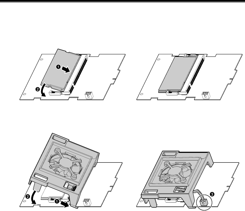
2. Insert the Raspberry Pi Compute Module into the NEC Compute Module Interface board (1),
make sure it is correctly seated and then press down on the compute module to lock it into the
board (2).
Caution: Take static precaution measures when handling the boards.
Figure 3.1-1: Install the Raspberry Pi Compute Module
3. Attach the fan assembly to the edges of the NEC Compute Module Interface board, and then
connect the fan power to the socket on the board.
Figure 3.1-2: Attach the Fan Assembly
©2019 NEC Display Solutions, Ltd. Page 13 of 74
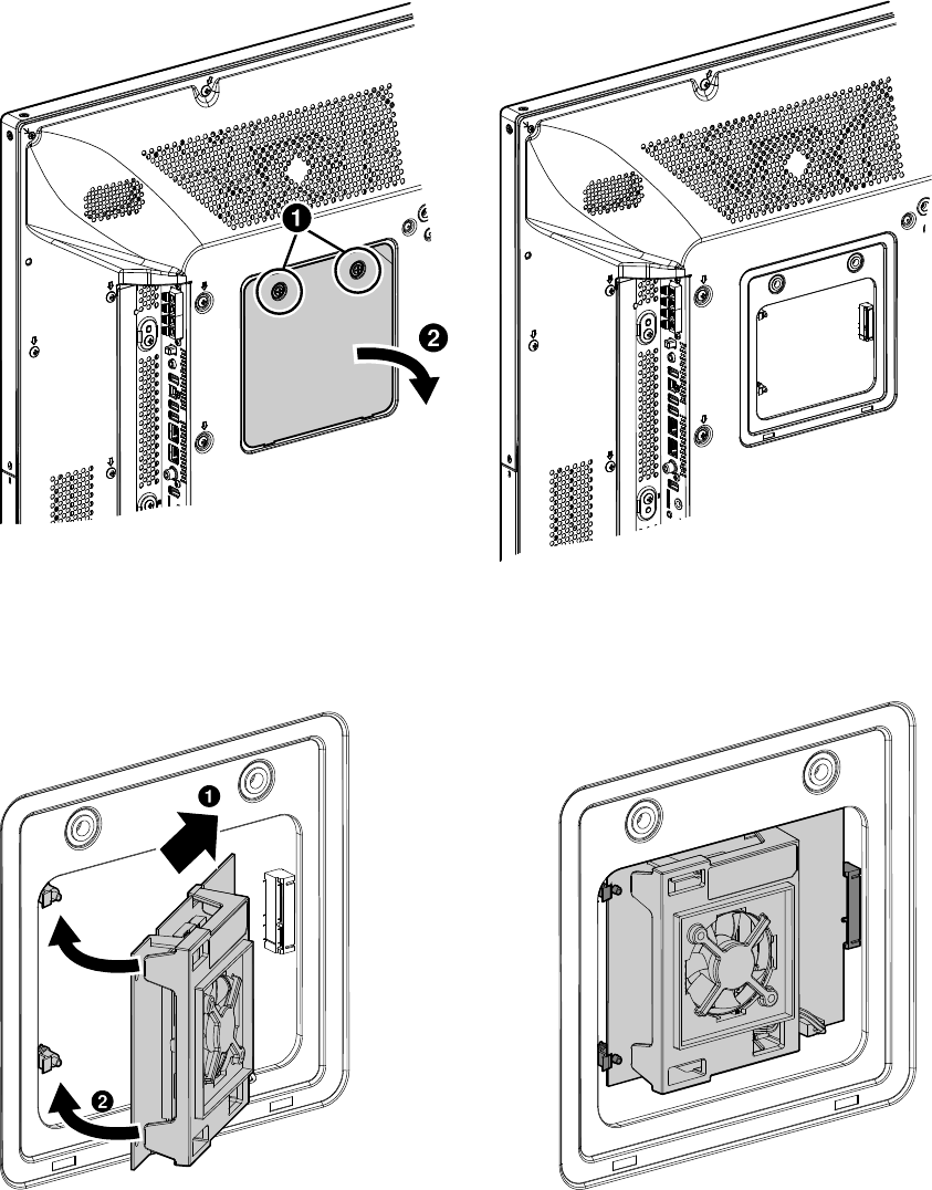
4. On the back of the display, unscrew the two screws on the interface board access cover and
remove the cover.
Figure 3.1-3: Remove the Interface Board Access Cover
5. Insert the edge connector on the interface board into the socket in the display and snap the
board into place with the two standoffs. Make sure the interface board is correctly seated.
Figure 3.1-4: Insert the Compute Module Interface Board
©2019 NEC Display Solutions, Ltd. Page 14 of 74
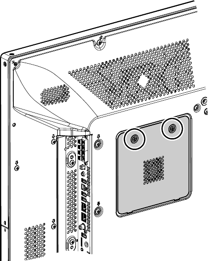
6. Place the vented access cover, included with the Compute Module interface board, on the back
of the display and tighten the two screws.
Figure 3.1-5: Place the Vented Access Cover
7. Reconnect AC power to the display.
©2019 NEC Display Solutions, Ltd. Page 15 of 74
3 Connections and Internal Operation
3.1 USB device connections to the Compute Module
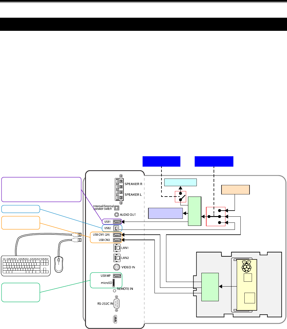
The inputs USB CM1 and USB CM2 on the display are for connecting downstream USB devices, such as
a keyboard and mouse, additional storage, or a Wi-Fi adapter, to the Compute Module. The CM1 input is
capable of supplying higher powered devices with up to 2A of current. The CM2 input can supply 500 mA.
Power for the USB CM1 input can be configured via the display’s OSD to always be on, even when the
display is in standby mode, or to only supply power if the Compute Module is installed.
The input connection USB1 can be switched between the Compute Module, Internal PC (OPS), and an
external PC connected to the USB2 connection. It can be configured via the display’s OSD “PC SOURCE”
setting to switch automatically depending on the currently selected video input, or fixed to a specific
source. This allows devices such as a mouse or other input device to be shared automatically between
different sources.
For display models with an integrated touch-screen, the internal USB connection from the touch sensor
will also follow the “PC SOURCE” setting so that as video inputs on the display are changed, the touch-
screen connection will automatically switch to the correct source device.
Compu
te
Module
USB
Hub
Raspberry Pi
Compute Module
Interface Board
HDMI IN1
Internal PC(OPS)
ENABLE / DISABLE
MONITOR CONTROL
Internal Touchscreen
connection (option)
Display USBControl
USB
Hub
PC SOURCE
AUTO
Shared between the Compute Module,
Internal PC (OPS), and External PC.
Controlled by the“PC SOURCE” setting
in “Control” -> “USB” on the OSD menu.
External PC input
Dedicated to the
Compute Module
Dedicated to the
Internal Media
Player
Figure 3.1-1: USB Device Connection
©2019 NEC Display Solutions, Ltd. Page 16 of 74
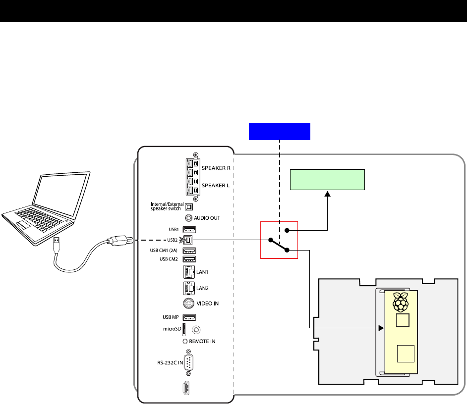
3.2 USB connections for programming the Compute Module
To program the Compute Module, an external “host” PC is connected to the USB2 output and the display
is placed into the special “USB Boot Mode” using the OSD. The Compute Module will then appear as a
USB device to the “host” PC, allowing the Compute Module to be programmed.
When not used for programming the Compute Module, the USB2 output on the display can be used to
control the display via USB from an external PC; depending on the PC SOURCE setting in the Control
USB function on the display’s OSD menu. See Related OSD on page 45.
Figure 3.2-1: Host USB Connection for Programming
C
ompu
te
Module
USB
Hub
Raspberry Pi
Compute Module
Interface Board
HDMI IN1
ENABLE / DISABLE
USB BOOT MODE
USB switch, hub, display
control, and other functions
©2019 NEC Display Solutions, Ltd. Page 17 of 74
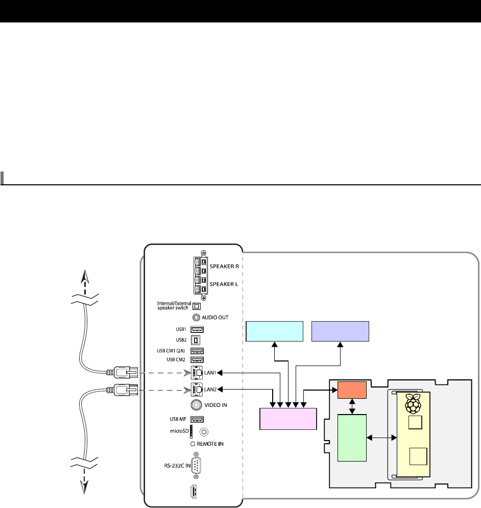
3.3 LAN connections
The display has an internal 5 device LAN switch that connects the internal Display LAN Control system
(including internal web server), internal Media Player, Raspberry Pi Compute Module, and the two
external LAN connections for connecting to a network and other LAN devices.
• The IP addresses of the Display LAN Control can be configured via the display’s OSD and internal
web page.
• The IP address of the internal Media Player can be configured via the internal web page.
• The IP address and network settings of the Compute Module are configured within the OS
running on it.
Note
The LAN2 connection should be used for connecting to other displays that are daisy-chained or to other
LAN devices. Functions such as AUTO ID and AUTO IP will not work correctly if displays are not daisy-
chained correctly using the LAN1 and LAN2 connections.
Figure 3.3-1: LAN Connections
Compute
Module
USB
Hub
Raspberry Pi
Compute Module
Interface Board
HDMI IN1
To Network
To Other Networked Devices
Display LANControl Internal Media Player
LAN Switch
Ethernet
Controller

©2019 NEC Display Solutions, Ltd. Page 18 of 74
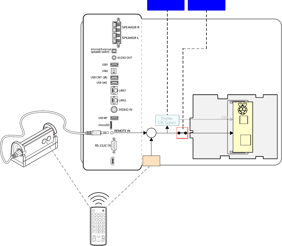
3.4 Software control via IR Remote
An IR Remote can be used to control software running on the Compute Module, such as a media player.
IR Remote control signals are received via the display’s built-in IR remote sensor or via an optional
external KT-RC2 sensor.
This feature can be used in two ways:
• As a CEC (Consumer Electronics Control) device
Specific buttons on the NEC IR Remote will perform actions, such as Stop, Play, Next, Previous,
etc., on CEC enabled software on the Compute Module. The display is responsible for receiving
and decoding the IR Remote signals, and then forwarding them on to the Compute Module as
standard CEC commands.
Only the NEC IR Remote can be used and CEC support must be enabled on the display and in the
Operating System on the Compute Module. See Figure 3.4-3: Supported CEC buttons on the NEC
IR Remote.
The buttons used for CEC commands are dual-function on the NEC IR Remote. When the
display’s OSD is active (being displayed) the buttons will perform display related functions.
When the OSD is not active the buttons will perform CEC functions. Press the EXIT button on the
IR Remote to exit and deactivate the OSD.
See sections 8.15 and 8.16 for more information.
• As a generic IR receiver
Demodulated raw IR signals received by the IR remote sensor are passed to the Raspberry Pi
Compute Module via GPIO 18. Packages such as lirc can be used to decode the raw IR signals.
IR Remotes other than the NEC IR Remote, such as a standard MCE/RC6 type, can be used as
long as they use a 40 KHz carrier. See sections 7.4 , 7.5 , and 8.5 for more information.

©2019 NEC Display Solutions, Ltd. Page 19 of 74
Compute
Module
USB
Hub
Raspberry Pi
Compute Module
Interface Board
HDMI IN1
ENABLE / DISABLE
IR SIGNAL
Display
CEC Control
CEC
ON / OFF
CEC
Front
IR Sensor
+
KT-RC2
(optional)
Figure 3.4-1: Using the NEC IR Remote with CEC
©2019 NEC Display Solutions, Ltd. Page 20 of 74
Compute
M
odule
USB
Hub
Raspberry Pi
Compu
te M
odule
I
nterface Board
HDMI IN1
ENABLE / DISABLE
IR SIGNAL
Display
CEC Control
GPIO18
ON / OFF
CEC
Front
IR Sensor
+
KT-RC2
(optional)
Figure 3.4-2: Using other IR Remotes with raw IR signals
©2019 NEC Display Solutions, Ltd. Page 21 of 74
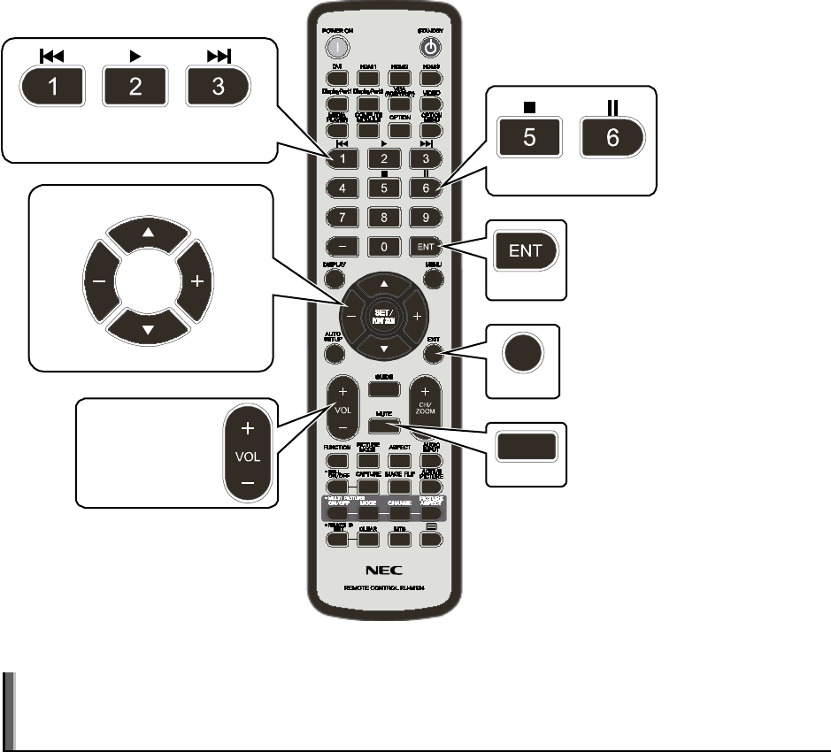
Mute
Volume Up
Volume Down
Exit
Enter
Stop Pause
Reverse/
Previous
Forward/
Next
Play
Left Right
Up
Down
Figure 3.4-3: Supported CEC buttons on the NEC IR Remote
Note: The Volume Up, Down and Mute buttons will control audio on the display rather than on any
media player software running on the Compute Module. These buttons will only operate in CEC mode
if a CEC compatible audio amp/receiver is used.

©2019 NEC Display Solutions, Ltd. Page 22 of 74
4 Preparation
Note: The following steps can be skipped if the Yodeck bootloader is installed on the system. The
Yodeck bootloader can be used to automatically overwrite the current OS image with an OS image
from a connected USB storage device. See “Using the Yodeck bootloader to overwrite the current OS”
on page 33 for more information.
1. Connect a USB keyboard and mouse to the USB CM1 and USB CM2 connections on the display.
These are the two connections above the LAN1 connection on the side of the display.
2. Connect the “B” type connector of a USB cable to the USB2 connection on the display. This is
located above the USB CM1 connection on the side of the display. Connect the other end of the
USB cable to a standard USB port on the host PC or host Raspberry Pi.
3. [Optional depending if updates and downloads will be performed] Connect the host PC or
Raspberry Pi to a hub or router with an Internet connection using a standard LAN cable or using
Wi-Fi.
4. On the host PC or the host Raspberry Pi, download the OS that is to be installed on the
Raspberry Pi Compute Module. Make sure there is enough storage space to hold the OS image
file and other tools.
Refer to the following section and the Raspberry Pi website for a list of supported OSs:
https://www.raspberrypi.org/downloads/
If using a Windows based host PC:
1. Download either the Etcher (recommended) or Win32DiskImager tool from the following
locations. This will be used to write the OS .img file to the Compute Module:
https://etcher.io/
https://sourceforge.net/projects/win32diskimager/
2. Download and install the Compute Module boot installer from the following location:
https://github.com/raspberrypi/usbboot/raw/master/win32/rpiboot_setup.exe
3. A text editor that is compatible with UNIX type line endings, such as Notepad++, is highly
recommended for making boot configuration file changes from Windows. Notepad++ is
available from:
https://notepad-plus-plus.org/
4. A file extractor application capable of handling .gz file types, such as 7-Zip, WinZIP, or WinRAR.

©2019 NEC Display Solutions, Ltd. Page 23 of 74
5 Operating System Summary
The following table summarizes the main Operating Systems available, as well as the main configuration
options that can be set.
Table 5-1: Operating System Distro
Operating System Distro
Raspbian
Jessie
Raspbian
Jessie
Lite
LibreELEC
OSMC
Ubuntu
MATE
Snappy
Ubuntu
Core
Windows
10 IOT
Core
NOOBS
Compatible
with
Compute
Module 1
No
†
Yes
Yes. Use
RPi 1/ RPi
Zero
version
Yes. Use
RPi 1/
RPi Zero
version
No
(requires
RPi 2 or
3)
No No No
Compatible
with standard
4GB
Compute
Module 3
No
†
Yes
7.0.3 RPi
2/3 = No.
7.90.010
and 8.0.0
RPi 2/3 =
Yes.
Yes. Use
RPi 2/3
version
No
§§§
Yes No No
Compatible
with
Raspberry Pi
Compute
Module 3
NEC edition
Yes Yes
7.0.3 RPi
2/3 = No.
7.90.010
and 8.0.0
RPi 2/3 =
Yes.
Yes. Use
RPi 2/3
version
No
§§§
Yes No No
Needs HDMI
pixel
encoding
changed
Yes
‡
Yes
‡
Yes
‡
Yes
‖‖
Needs HDMI
overscan
setting
change
Yes
††
Yes
††
No No
Includes lirc
IR Remote
support
Yes
‖
Yes
‖
Yes
§
Yes
†††
Serial port
name
CM3:
ttyS0
CM1:
ttyAMA0
CM3:
ttyS0
CM1:
ttyAMA0
CM3:
[TBC]
CM1:
[TBC]
CM3:
[TBC]
Needs serial
port
configuration
Yes
‡‡‡
Yes
§§
Yes
[TBC]
Python serial
module
Included
‡‡
Not
included
‡‡
Default
username /
password
pi /
raspberry
pi /
raspberry
root /
libreelec
osmc /
osmc
ubuntu /
ubuntu
Confirmed
with version
November
2016
November
2016
7.0.3,
7.90.010
and 8.0.0
2016.12-
1
16.04.01
LTS
2.1.0
Alternate tool
for
loading .img
to Compute
Module
“LibreELEC
USB-SD
Creator”

©2019 NEC Display Solutions, Ltd. Page 24 of 74
Note: Many of the options for the Raspbian OS can be automatically configured using the Compute
Module Configuration Tool for Raspbian see “Compute Module Configuration Tool for Raspbian” on
page 67.
Note: On Raspbian based OSs the config.txt and cmdline.txt files are located in the /boot
folder of the mounted OS.
†
The onboard flash eMMC storage, for the Raspberry Pi Compute Module 1, is 4GB and is not large
enough for the full version of the Raspbian Operating System. The “Lite” version can be installed but will
only provide a command shell interface by default. See chapter 9 for an example of how to install a
minimal windowing system on Jessie Lite that is less than 4GB in size.
‡
Edit the file config.txt to add the line “hdmi_pixel_encoding=2”
§
Edit the file config.txt to add the line “dtoverlay=lirc-rpi” to enable IR support. Standard MCE
type IR is supported by default.
‖
Edit the file config.txt to remove the “#” at the start of the line “#dtoverlay=lirc-rpi” to enable
IR support.
††
Edit the file config.txt to remove the “#” at the start of the line “#disable_overscan=1” to
prevent black borders.
‡‡
Install the Python Serial module by entering the following from the terminal:
sudo apt-get install python-serial
§§
Edit the file config.txt to add, or modify, so that a line with “enable_uart=1” is in the file. Edit the
file cmdline.txt to remove the following text “console=serial0,115200” if present.
‖‖
On the “My OSMC” menu, select “Pi Config” and in the “Display” section change the
“hdmi_pixel_encoding” setting to “RGB full”.
†††
Edit the file config.txt to add the line “dtoverlay=lirc-rpi” to enable IR support. On the “My
OSMC” menu, select “Remote” and select “rc6-mce-lircd” type remote for a standard MCE type IR
remote.
‡‡‡
Modify the file config.txt to include the following lines:
enable_uart=1
dtoverlay=uart1
core_freq=250
Edit the file cmdline.txt to remove the following text “console=serial0,115200” if present.
§§§
Device Tree file for Compute Module 3 (bcm2710-rpi-cm3.dtb) not yet added to image.

©2019 NEC Display Solutions, Ltd. Page 25 of 74
Note
If there are different system build images available for various versions of Raspberry Pi, such as with
LibreELEC and OSMC, be sure to select the correct build version for the version of the Raspberry Pi
Compute Module being used.
For example, if downloading LibreELEC for use with a Compute Module:
• If using the Compute Module 1 then select the “RPi and Pi Zero (Combined) Build”.
• If using the Compute Module 3 then select the “RPi2 and RPi3 (Combined) Build”.
©2019 NEC Display Solutions, Ltd. Page 26 of 74
6 Preparing and Running the Tools to Make the
Compute Module Appear as a Mass Storage Device
Follow the steps in the appropriate section below depending on the type of host system being used.
6.1 Using a Windows PC as a host
1. Download and install either the Etcher (recommended) or Win32DiskImager tool from the
following locations. This will be used to write the OS .img file to the Compute Module:
https://etcher.io/
https://sourceforge.net/projects/win32diskimager/
2. Download and install the Compute Module boot installer. This will install Windows drivers for
accessing the Compute Module.
https://github.com/raspberrypi/usbboot/raw/master/win32/rpiboot_setup.exe
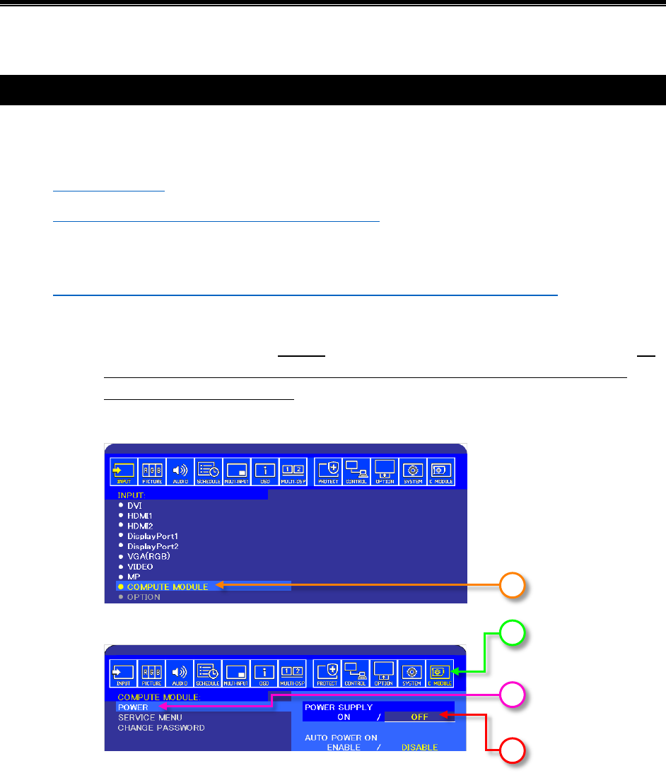
3. Power up the Compute Module in USB boot mode:
a. Make sure the USB cable is directly connected between the host PC and the display. Do
not use a USB extender cable or hub between the host PC and the display. Use as
short a USB cable as possible.
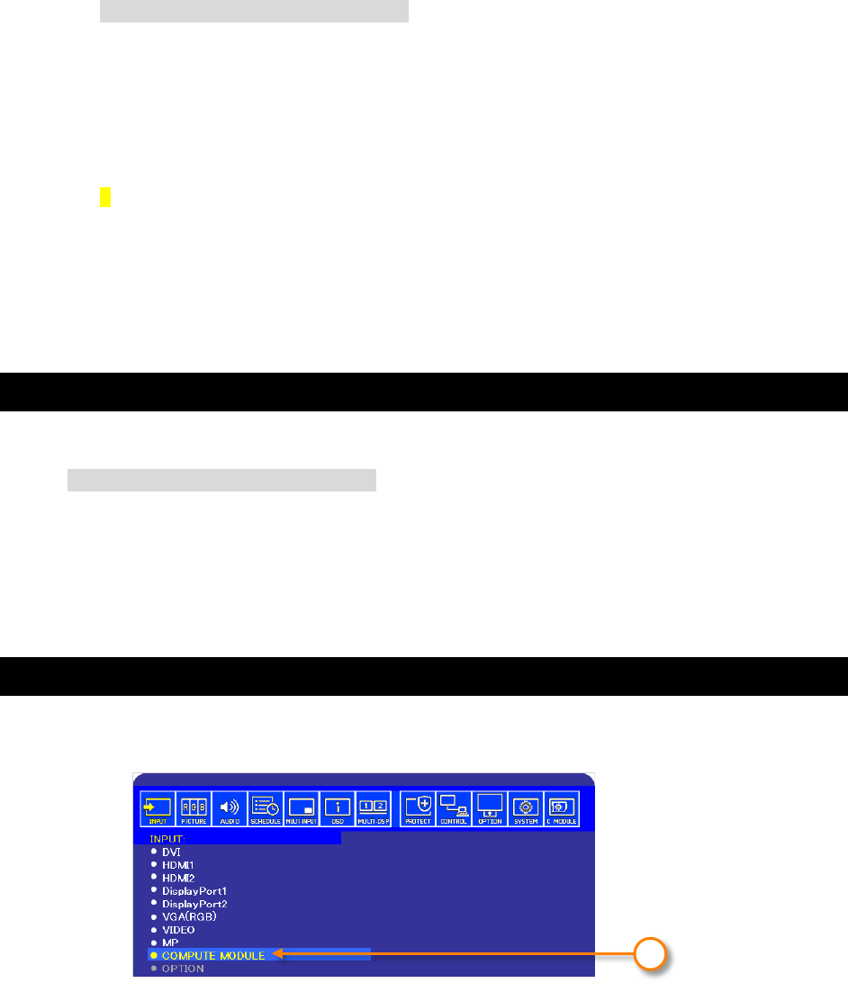
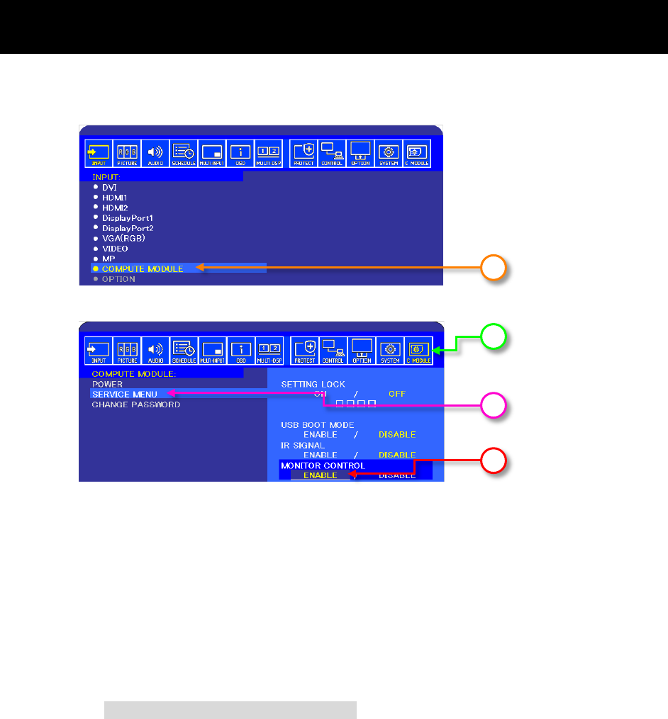
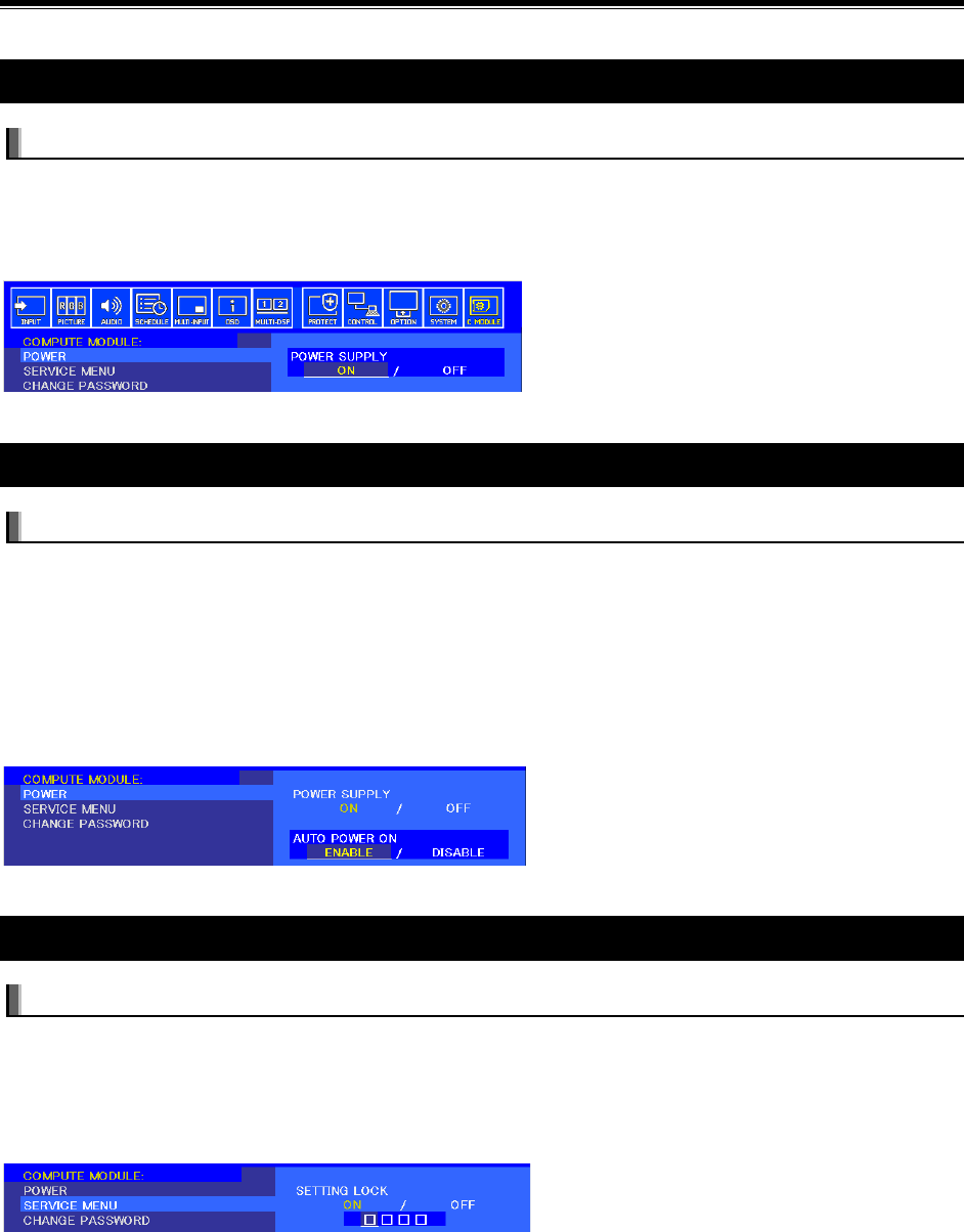
b. On the NEC display select the COMPUTE MODULE video input.
c. Navigate to the COMPUTE MODULE menu on the OSD.
d. Select POWER.
e. If POWER SUPPLY is currently ON then change it to OFF and confirm.
b
c
e
d
©2019 NEC Display Solutions, Ltd. Page 27 of 74
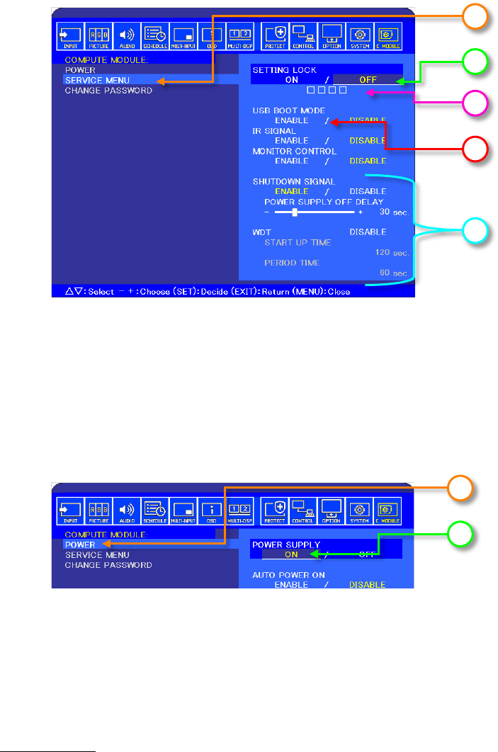
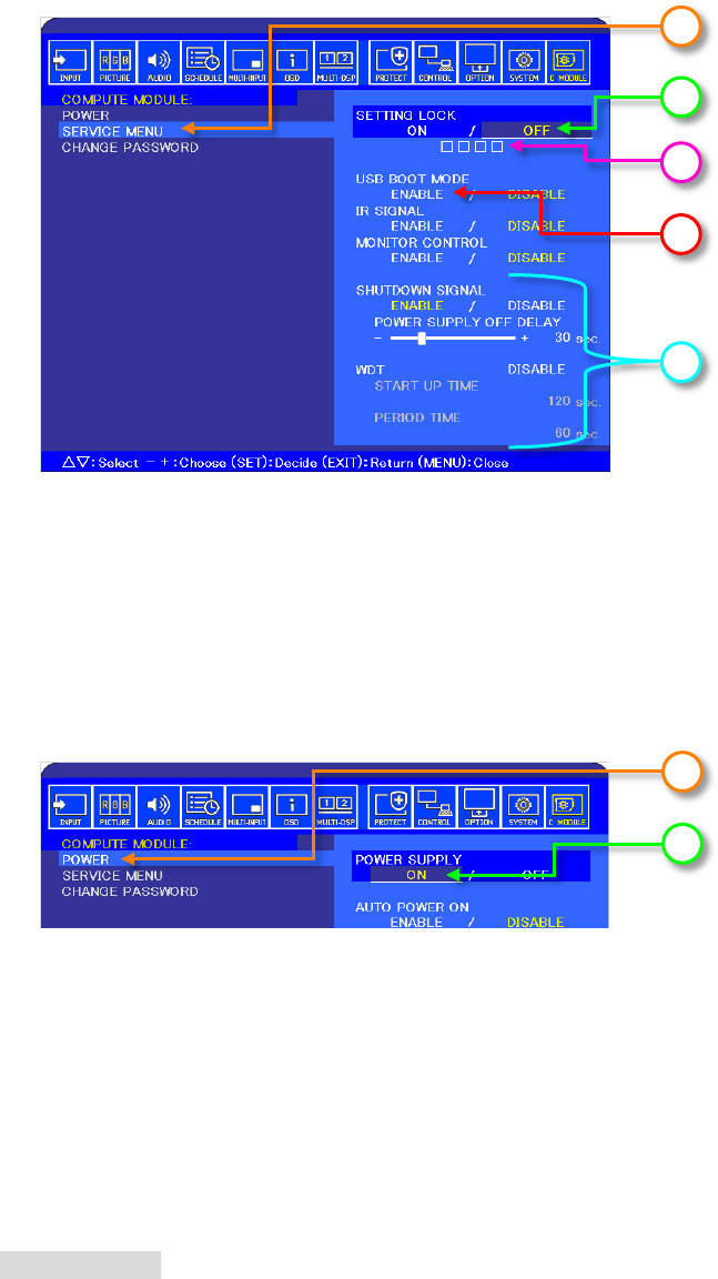
f. Select SERVICE MENU.
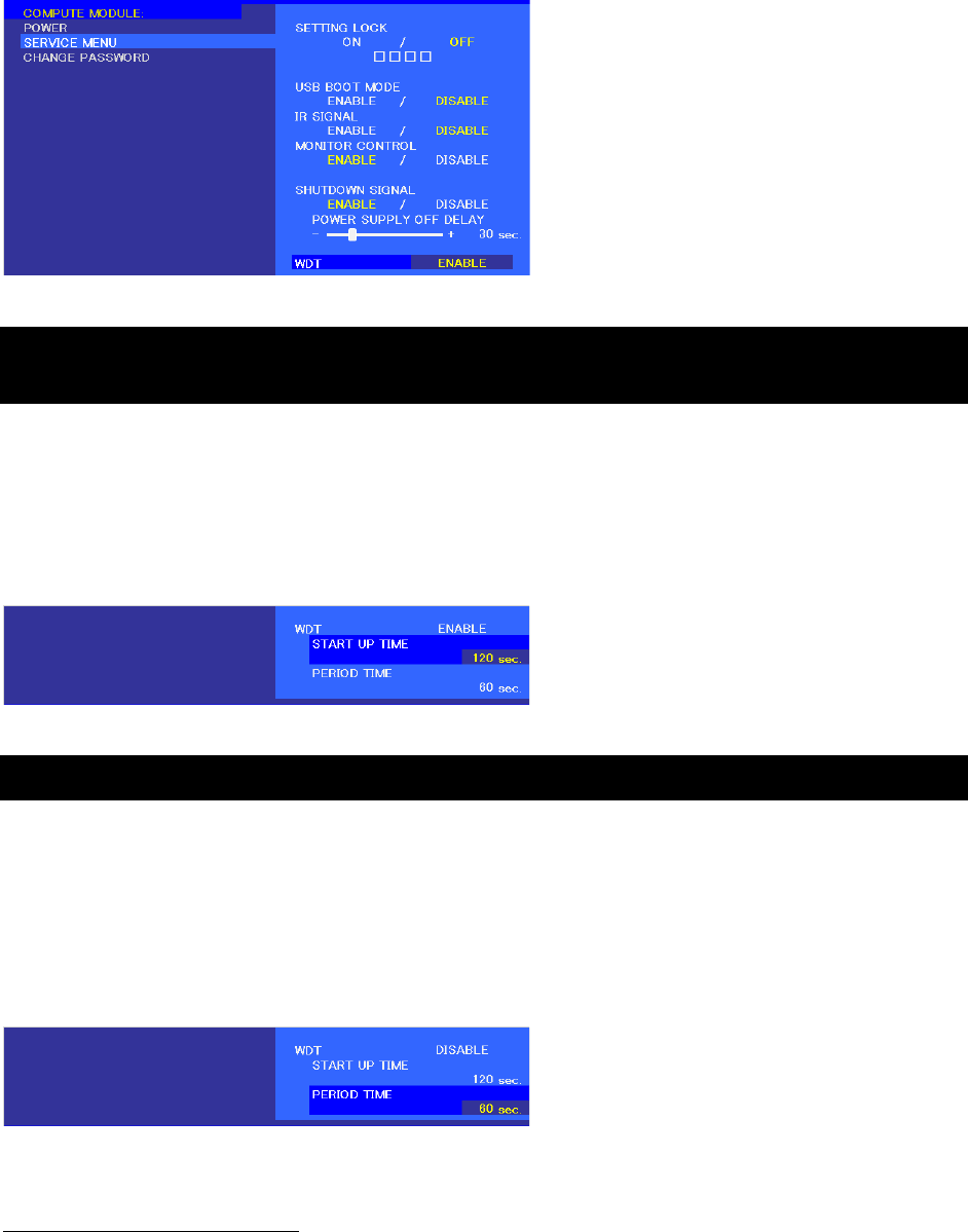
g. Select SETTING LOCK and then select OFF.
h. Enter the passcode. The default is 0 0 0 0.
i. Select USB BOOT MODE and then select ENABLE.
j. It is also recommended setting SHUTDOWN SIGNAL to DISABLE and WDT to DISABLE
during programming.
k. Exit two levels and navigate to the POWER item on the COMPUTE MODULE menu.
l. Select POWER SUPPLY and then select ON.
Important: If the display goes into standby mode or Compute Module is powered off and on,
it will automatically cancel USB BOOT MODE. Be sure to check that the boot mode is as
intended if the process needs to be restarted.
4. Run the Win32DiskImager or Etcher tool and select the downloaded OS .img file.
If using Etcher:
a. Launch the Etcher application.
b. Select the downloaded OS .img file as the source image.
c. The Compute Module should automatically appear as the destination drive.
f
g
h
i
j
k
l

©2019 NEC Display Solutions, Ltd. Page 28 of 74
d. Click “Flash!” to begin writing and verifying the image. This process should take
approximately 5 to 15 minutes.
e. When finished, the drive should contain the boot files for the OS.
If using Win32DiskImager:
a. Run the Compute Module boot application “rpiboot”, installed on the “Raspberry Pi”
Windows Start menu. A window should appear with “Waiting for
BCM2835/6/7”.
Note: The Compute Module boot installer makes the Compute Module appear as a USB
mass storage device to Windows. This step must be performed each time the Compute
Module is placed into USB Boot Mode and powered on.
The “rpiboot” command window should show some text and disappear.
A new mass storage device should show as a new drive letter on the host PC. Windows
may display a message saying the device needs to be formatted before use – ignore this
message as it will be formatted by imaging it.
See the “Troubleshooting” section on page 61 of this guide if a new mass storage device
doesn’t appear.
b. Run the Win32DiskImager tool and select the downloaded OS .img file.
c. Select the new drive as the Target Device. Make sure the correct drive is selected as all
data will be overwritten.
d. Write the file to the Compute Module. This should take approximately 5 to 15 minutes.
When finished, the drive should contain the boot files for the OS.
Note: The display may go into a power save mode because there is no signal from the Compute
Module (the power led will flash green). The internal Compute Module will remain powered on and can
be flashed.
Important: If the display or Compute Module is powered off and on, it will automatically cancel
USB BOOT MODE. Make sure the boot mode is as intended if the process needs to be restarted.
5. Configuring boot options:
Some settings in the boot files
config.txt and cmdline.txt can be modified at this
stage. For example, settings to correctly set the video output level and to enable the IR
Remote module (lirc) can be made while still in Windows.
Navigate to the drive letter of the Compute Module to see the boot files.
Use a text editor that is compatible with UNIX type line endings such as Notepad++
(https://notepad-plus-plus.org/
)
See other sections of this document for further information on specific configurations.
©2019 NEC Display Solutions, Ltd. Page 29 of 74
6. The Compute Module in the display can now be restarted in normal mode to boot the device.
(Example screens for navigating through the OSD controls are in step 4 above):
a. On the NEC display select the COMPUTE MODULE video input.
b. Navigate to the COMPUTE MODULE menu on the OSD.
c. Navigate to the SERVICE MENU item on the COMPUTE MODULE menu.
d. If the USB BOOT MODE setting is still set to ENABLE change it to DISABLE.
e. Navigate to the POWER item on the COMPUTE MODULE menu.
f. Select POWER SUPPLY to OFF.
g. Wait for power to the Compute Module to be shutdown. When navigating back to the
same menu item it should now show POWER SUPPLY OFF.
h. Select POWER SUPPLY to ON.
The boot-up sequence for the Compute Module should be seen on the screen.
Note: If the system hangs at the rainbow start screen, the operating system may not be compatible
with the model of the Compute Module being used.
7. Check for any system and firmware updates. See section 9.1.7.
6.2 Using a Raspberry Pi 1, 2, or 3 as a host
When using Raspberry Pi 1/2/3 as a host, perform the following steps to download, compile, and run the
“rpiboot” tool. This will make the Compute Module appear as a Mass Storage device. These steps only
need to be done once in order to make the tool. Skip to the last step if this has already been done.
Note: An Internet connection is required for these steps.
1. Open a terminal window and confirm that the internal date is correct by entering:
date
If the date is not correct enter the current date in a terminal window:
sudo date MMDDhhmm
Where MM is month, DD is day, and hh and mm is hours and minutes respectively.
2. Make sure the host system is up to date using the following commands in a terminal widow:
Note: These may take 10 or more minutes to complete. Answer “y” if prompted.
sudo apt-get update
sudo apt-get upgrade
sudo rpi-update
reboot
3. After it has restarted open a terminal window again.
©2019 NEC Display Solutions, Ltd. Page 30 of 74
cd Desktop
Clone the usbboot tool repository:
git clone --depth=1 https://github.com/raspberrypi/usbboot.git
cd usbboot
4. Install libusb using the following command:
sudo apt-get install libusb-1.0-0-dev
5. Now build and install the usbboot tool:
make
sudo make install
Run the usbboot tool and it will wait for a connection:
sudo rpiboot
You should see
Waiting for BCM2835/6/7
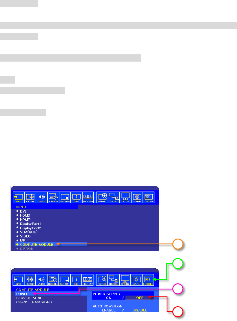
6. Power up the Compute Module in USB boot mode:
a. Make sure the USB cable is directly connected between the host PC and the display. Do
not use a USB extender cable or hub between the host PC and the display.
b. On the NEC display select the COMPUTE MODULE video input.
c. Navigate to the COMPUTE MODULE menu on the OSD.
d. Select POWER.
e. If POWER SUPPLY is currently ON then change it to OFF and confirm.
b
c
e
d
©2019 NEC Display Solutions, Ltd. Page 31 of 74
f. Select SERVICE MENU.
g. Select SETTING LOCK and then select OFF.
h. Enter the passcode. The default is 0 0 0 0.
i. Select USB BOOT MODE and then select ENABLE.
j. It is also recommended setting SHUTDOWN SIGNAL to DISABLE and WDT to DISABLE
during programming.
k. Exit two levels and navigate to the POWER item on the COMPUTE MODULE menu.
l. Select POWER SUPPLY and then select ON.
Important: If the display goes into standby mode or the Compute Module is powered off and on,
it will automatically cancel USB BOOT MODE. Be sure to check the boot mode is as intended if
the process needs to be restarted.
7. On the Raspberry Pi the terminal window that was used to run rpiboot should now show:
Initialized device correctly
Confirm the name of the device given to the Compute Module on the system by entering the
command:
ls /dev/sd*
This should list at least one device such as “/dev/sda/”.
If the Compute Module has previously been flashed, it may also list partitions such as
“/dev/sda1/” and “/dev/sda2”
f
g
h
i
j
k
l

©2019 NEC Display Solutions, Ltd. Page 32 of 74
If other devices, such as “/dev/sdb”, are listed it could indicate that another USB drive is
currently connected. Disconnect the drive and repeat this step.
8. Flash the OS image to the Compute Module.
Navigate to the folder where the image file was downloaded and unzipped.
For example, from a new terminal window:
cd Downloads
Perform a directory listing to confirm the name of the image file:
ls
Write the downloaded image to the Compute Module using:
sudo dd if=xxxxxxxx.img of=/dev/sda bs=4MiB
Where xxxxxxxx.img is the name of the image file to write.
Note: This step will take several minutes to complete and erases all data on the Compute
Module.
When it is finished, confirm the “records in” matches the “records out”.
9. The Compute Module in the display can now be restarted in normal mode to boot the device
(Example screens for navigating through the OSD controls are in step 6 above):
a. On the NEC display select the COMPUTE MODULE video input.
b. Navigate to the COMPUTE MODULE menu on the OSD.
c. Navigate to the SERVICE MENU item on the COMPUTE MODULE menu.
d. If the USB BOOT MODE setting is still set to ENABLE change it to DISABLE.
e. Navigate to the POWER item on the COMPUTE MODULE menu.
f. Select POWER SUPPLY to OFF.
g. Wait for power to the Compute Module to be shutdown. If you navigate to the same
menu item it should now show POWER SUPPLY OFF.
h. Select POWER SUPPLY to ON.
i. The boot-up sequence for the Compute Module should be seen on the screen.
8. Check for any system and firmware updates. See section 9.1.7.

©2019 NEC Display Solutions, Ltd. Page 33 of 74
7 Using the Yodeck bootloader to overwrite the
current OS
Yodeck Digital Signage has developed a special bootloader that can be used to replace the current OS
image with another image located on a connected USB storage device. This can be done without the
need to configure the display settings or connect a host PC, keyboard, or mouse.
This bootloader is included on newer releases of the NEC Edition Compute Module; it can also be
installed using the Compute Module Configuration Tool for Raspbian (see page 67). Look for the orange
Yodeck logo during boot to see if it is installed on the current OS image.
If the bootloader is installed on the system, it will search for connected USB storage devices and scan for
OS image files. If an OS image is found, the bootloader then writes the contents of that file to the
Compute Module’s eMMC – automatically overwriting the current OS image.
An OS image can be an .img file, or a ZIP file containing an .img file, stored in the root folder on a USB
storage device formatted in FAT, FAT32, NTFS, EXT2, EXT3 or EXT4. The file name must begin with
“RaspberryPi” or “AUTORaspberryPi” and end in “.zip” or “.img” for it to be recognized by the
bootloader.
A single image file located on the USB storage device with a name starting with “AUTORaspberryPi” will
automatically start overwriting the current system without any user intervention.
An image file name starting with “RaspberryPi” causes a selection to be shown on the boot screen, the
image can then be manually selected using a USB keyboard.
If there are no matching image files found by the bootloader, the normal boot process will continue in a
few seconds.
Important: The bootloader will replace the entire OS image on the Compute Module’s eMMC. All
existing data will be lost. Also, the bootloader does not persist after the OS image is replaced. To
use it again, it must be re-installed.
To use the bootloader, copy a suitably named valid OS image file to a USB storage device and insert it
into either the USB CM1 or CM2 connectors on the display. Restart the Compute Module from the OSD
or cycle power to the display.
Note: USB flash drives are preferred over USB hard drives. If a flash drive does not work, try another
brand/model.
©2019 NEC Display Solutions, Ltd. Page 34 of 74
8 Miscellaneous Configuration Items
Note: Many of the options for the Raspbian OS can be automatically configured using the Compute
Module Configuration Tool for Raspbian see “Compute Module Configuration Tool for Raspbian” on
page 67.
8.1 Configuring the correct HDMI video level encoding and decoding
The Compute Module can output video to displays that have video levels either in the range 0-255
(known as “full”) or in the range 16-235 (known as “limited” or “RGB limited”). Configuration settings for
the OS determine which range will be output. The NEC display can accept either range sets and will
display the video correctly, as long as it is configured correctly to match the video range from the
Compute Module. However, it is recommended to use the “full” range since it will give the maximum
number of displayable colors.
A mismatch between the output range from the Compute Module and the display will result in either:
• Blacks appearing as gray and whites being too dark.
o Cause: Compute Module outputs “limited” video range and the display is set to “RAW”.
Or
• Dark gray levels being crushed and whites being clipped.
o Cause: Compute Module outputs “full” video range and the display is set to “Expand”.
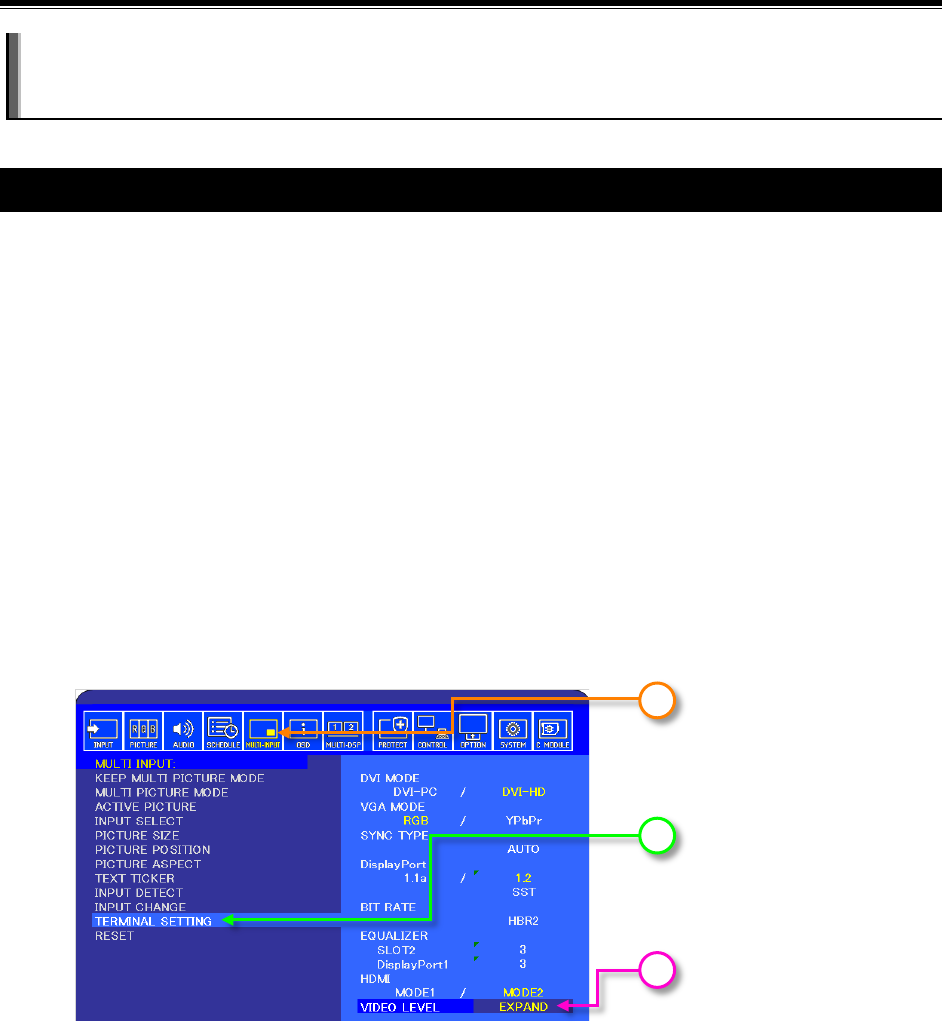
The video range used by the display is configured as follows:
1. Navigate to the MULTI INPUT menu on the OSD.
2. Select TERMINAL SETTINGS.
3. The VIDEO LEVEL setting determines how the display will handle the video from the Compute
Module.
• RAW - Use RAW if the Compute Module is configured to output “full” video in the range 0-
255. This is the recommended configuration since it provides the maximum number of
displayable colors. The display will not modify the range of the video signal levels.
1
2
3

©2019 NEC Display Solutions, Ltd. Page 35 of 74
• EXPAND - Use EXPAND if the Compute Module is configured to output “limited” video in the
range 16-235. The display will expand the video from the range 16-235 to 0-255 internally.
The video range used by the Compute Module depends on the Operating System. By default and
depending on the OS, many distributions will automatically output a video signal to the display that uses
video levels 16 to 235. A configuration file or menu setting is used to configure the video level. See “Table
5-1: Operating System Distro” for details about each OS.
For Raspbian and many other OS distros, the current video settings can be confirmed by typing the
following into a terminal window:
tvservice –s
The output should show something similar to the following:
“HDMI CEA (16) RGB lim 16:9, 1920x1080 @ 60.00 Hz, progressive”
If “lim” is shown, it means that limited 16 – 235 video is being output to the display.
To change this setting, a configuration file must be edited. If changing the setting from the Compute
Module itself, use the built in text editor “Nano” to edit the config.txt file:
sudo nano /boot/config.txt
Scroll to the end of the file and enter the following line:
hdmi_pixel_encoding=2
Save the file by pressing CONTROL + o then ENTER
Exit Nano by pressing CONTROL + x
Restart the Compute Module by typing:
sudo reboot
When rebooted, confirm the video levels are correct by using the following command again:
tvservice –s
The output should now show “full”
“HDMI CEA (16) RGB full 16:9, 1920x1080 @ 60.00 Hz, progressive”
8.2 To disable overscan (if black bars are visible on the sides of the
screen)
Either
• Run the Raspberry Pi Config utility
sudo raspi-config
Select: 9 Advanced Options
©2019 NEC Display Solutions, Ltd. Page 36 of 74
Select: A1 Overscan
Select: No
Or
• Edit the config.txt file to disable overscan:
sudo nano /boot/config.txt
Look for the following section:
# uncomment this if your display has a black border of unused pixels
visible
# and your display can output without overscan
#disable_overscan=1
Edit the last line to remove the #.
disable_overscan=1
Save the file and reboot.
8.3 To rotate the screen image to portrait orientation
Edit the config.txt file:
sudo nano /boot/config.txt
Add a new line:
display_rotate=3
Save the file and reboot.
8.4 To enable support for the IR Remote receiver using “lirc”
1. Make sure the display support is enabled.
a. On the NEC display select the COMPUTE MODULE video input.
a
©2019 NEC Display Solutions, Ltd. Page 37 of 74
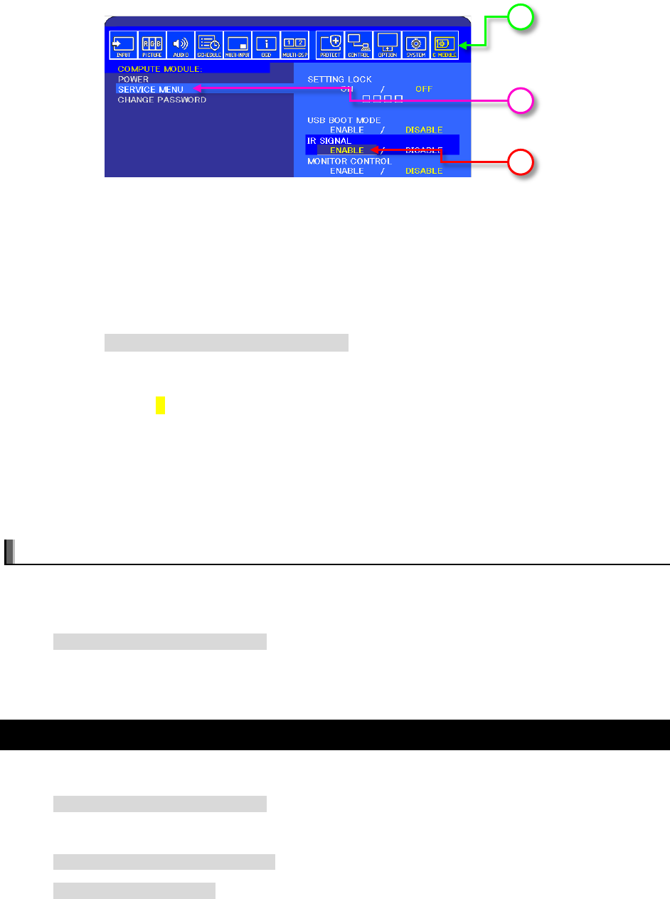
b. Navigate to the COMPUTE MODULE menu on the OSD.
c. Select SERVICE MENU.
d. Confirm that the IR SIGNAL is set to ENABLE.
e. If not set, then:
i. Select SETTING LOCK and then select OFF.
ii. Enter the passcode. The default is 0 0 0 0.
iii. Select IR SIGNAL and select ON.
2. Edit the config.txt file to enable support for lirc:
sudo nano /boot/config.txt
a. Look for the following section:
#uncomment this to enable the lirc-rpi module
#dtoverlay=lirc-rpi
b. If present, edit the last line to remove the # otherwise add the following line to the end
of the list:
dtoverlay=lirc-rpi
c. Save the file by pressing CONTROL + o then ENTER.
d. Exit Nano by pressing CONTROL + x.
Notes:
• A reboot is usually necessary to enable support.
• If lirc support is not included with the OS, it can be installed using the following:
sudo apt-get install lirc
• Additional configuration may be required in the OS and application being used.
8.5 To test support for the IR Receiver by outputting raw data
Make sure lirc is installed using:
sudo apt-get install lirc
Output raw data from the IR receiver as follows:
sudo /etc/init.d/lirc stop
mode2 -d /dev/lirc0
b
d
c
©2019 NEC Display Solutions, Ltd. Page 38 of 74
Point an IR Remote at the IR sensor on the display and press some buttons. Output should be seen
showing the raw pulses received.
8.6 Enabling the serial port (UART) to the display and allowing
application access
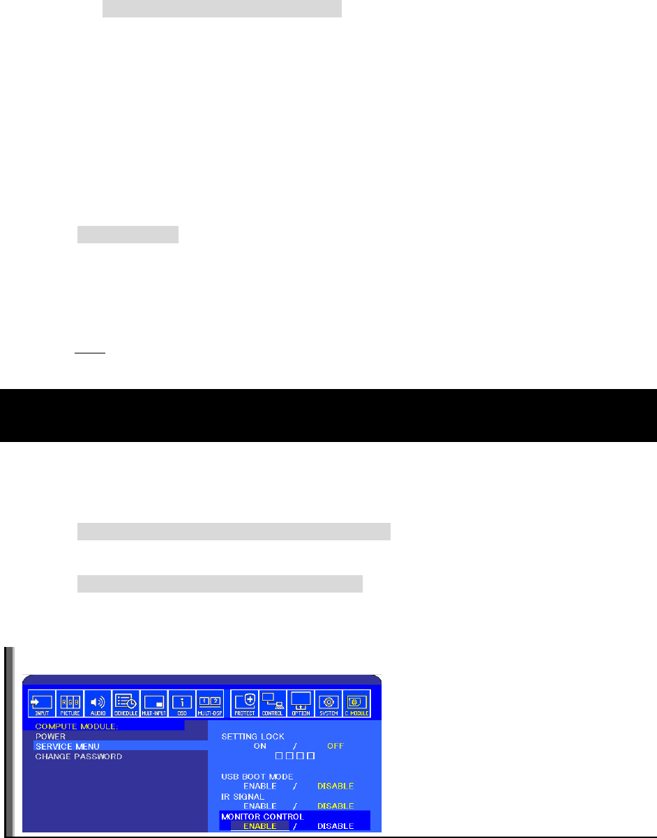
1. Make sure the display support is enabled.
a. On the NEC display select the COMPUTE MODULE video input.
b. Navigate to the COMPUTE MODULE menu on the OSD.
c. Select SERVICE MENU.
d. Confirm the MONITOR CONTROL is set to ENABLE.
e. If not set, then:
i. Select SETTING LOCK and then select OFF.
ii. Enter the passcode. The default is 0 0 0 0.
iii. Select MONITOR CONTROL and then select ENABLE.
2. Edit the cmdline.txt file to allow app access to the serial port and prevent bootup information
being sent to the display:
sudo nano /boot/cmdline.txt
Edit to remove the section “console=serial0,115200” or similar such as
“console=ttyAMA0,115200”
Save the file by pressing CONTROL+o then ENTER.
Exit Nano by pressing CONTROL + x.
a
b
d
c
©2019 NEC Display Solutions, Ltd. Page 39 of 74
3. Edit the config.txt file to allow application access to the serial port:
sudo nano /boot/config.txt
Edit to either add or change so there is a line with “enable_uart=1”
If using the Compute Module 3 add the following two lines:
dtoverlay=uart1
core_freq=250
Save the file by pressing CONTROL+o then ENTER.
Exit Nano by pressing CONTROL + x.
4. Reboot using:
sudo reboot
Important: When the Raspberry Pi boots up, all of the bootup information can be sent to the serial port
for debugging purposes. Since this serial port is connected internally to the display, this may overwhelm
the display and cause erratic behavior (such as the OSD flashing, random operations being performed,
slow bootup of the Compute Module, etc.). If the internal connection is enabled (the MONITOR
CONTROL setting on the COMPUTE MODULE menu of the OSD is set to ENABLE) then the bootup
information must be disabled.
8.7 Testing internal serial communications to the display using the
Python based NEC PD SDK
1. Install the Python based NEC PD SDK files, and download the examples. See Python Based NEC
PD SDK on page 65.
2. If necessary, install the Python serial module. This should normally be automatically installed.
sudo apt-get install python-serial
3. Run the test file in the SDK.
python test_routines_example.py
4. The application should output information about the display, such as model name and serial
number.
Note: Confirm the MONITOR CONTROL is set to ENABLE on the OSD.
©2019 NEC Display Solutions, Ltd. Page 40 of 74
8.8 Configuring the Compute Module to shutdown using shutdown
signal from the display
An example Python script rpi_shutdown.py is included with the Python based NEC PD SDK. The
script shows how to monitor GPIO 23 for a high to low transition, and how to use this to gracefully
shutdown the Operating System on the Compute Module before power to the module is removed by the
display. Normally this script should be started when the Operating System starts. This can be
accomplished by adding it to the /etc/rc.local file on the system. See the instructions provided in the
sample file for more details.
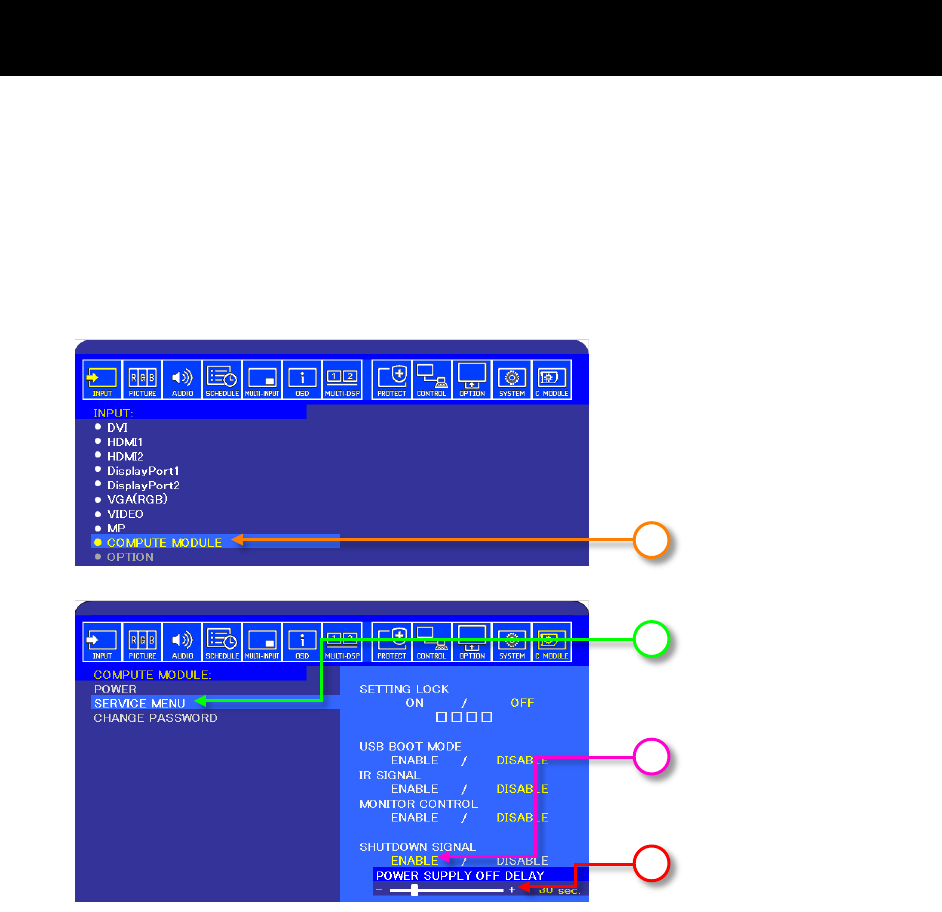
To enable the Shutdown Signal from the display:
1. On the NEC display navigate to the COMPUTE MODULE menu on the OSD.
2. Select SERVICE MENU.
3. Confirm that the SHUTDOWN SIGNAL is set to ENABLE.
If not set, then:
a. Select SETTING LOCK and then select OFF.
b. Enter the passcode. The default is 0 0 0 0.
c. Select SHUTDOWN SIGNAL and then select ENABLE.
4. Adjust the POWER SUPPLY OFF DELAY setting to set the delay between setting the shutdown
signal (GPIO 23 goes low) and power to the Compute Module being turned off by the display.
1
2
3
4

©2019 NEC Display Solutions, Ltd. Page 41 of 74
8.9 Creating an image of the Compute Module to backup or clone
Follow the steps to connect to a Windows host PC and place the Compute Module into USB BOOT
MODE.
Run the Win32DiskImager software and instead of selecting Write, select Read to read the drive and
store as an .img file.
Note: Because the entire expanded system will be copied, the resulting .img file will be the size of the
flash capacity of the Compute Module (e.g. 4GB for the standard Compute Module 1 and 3, and 16GB
for the Raspberry Pi Compute Module 3 NEC edition)
If imaging Raspbian OS from a Linux machine, the image file can be reduced in size using a tool such as
PiShrink. This will reduce the time it takes to upload the image to other Compute Modules, the image will
be expanded to the full size when the Compute Module is first booted. Extreme care should be taken to
ensure that the re-expanded image is correct before distributing.
PiShrink is available on GitHub:
https://github.com/Drewsif/PiShrink
8.10 Reading and setting the display’s internal Real Time Clock (RTC)
from the OS
The Compute Module doesn’t include a Real Time Clock so the correct time must be configured at each
startup. This is usually done via a network connection to an NTP time server; however, the Compute
Module can read the display’s internal Real Time Clock as well.
The display’s internal Real Time Clock can be read and set from the Compute Module via the internal
serial connection (UART). This can be useful in situations where the Compute Module is unable to get the
current time from the network.
The Python based NEC PD SDK includes the following sample files:
• set_system_to_display_clock.py - Reads the display’s internal clock via the internal
serial connection and sets the system time accordingly. This file can be added to a startup script
on the system, if necessary, in order to set the OS time from the display if no network
connection is available.
•
set_display_to_system_clock.py - Sets the display’s internal clock based on the current
system time on the Compute Module.
See the files included in the SDK for more details. See Python Based NEC PD SDK on page 65.
8.11 Using the display’s Watchdog Timer (WDT)
The display features an internal Watchdog Timer that can be used to automatically restart the Compute
Module if it stops responding; for example, if it hangs for some reason.
©2019 NEC Display Solutions, Ltd. Page 42 of 74
To use this feature, a background application is configured to periodically send reset commands to the
display via the internal UART. The display will expect to receive these reset commands as an indication
that the Compute Module is functioning normally. If, for some reason, the reset commands aren’t received
as expected the display will shut down and restart the Compute Module.
Use of the Watchdog Timer is optional and requires configuring the Operating System to start the
background application at bootup. The Watchdog Timer is enabled and configured via the OSD or
communications commands. The background application must send the reset command at least as often
as the Period Time configured via the OSD. If two consecutive resets commands aren’t received, the
display will restart the Compute Module.
There are two time periods that can be configured for the Watchdog Timer:
• Start Up Time – This sets the time delay for when the display should start receiving WDT reset
commands, via the internal UART, after power is applied to the Compute Module.
This timer’s value should be set high enough to include time for the operating system to fully
load on the Compute Module, and for the periodic reset commands to begin sending to the
display.
• Period Time – This sets the maximum amount of time within which the display must receive
WDT reset commands from the Compute Module, via the internal UART. If two consecutive
reset commands are missed, the display will restart the Compute Module.
This timer’s value should be set high enough to ensure that any software running on the
Compute Module will be able to send the periodic reset command to the display, even under
heavy load conditions.
The Python SDK includes support for sending the Watchdog Timer reset commands to the display, as
well as configuring the timer settings. See the example file reset_display_wdt.py included in the
SDK for more details. See Python Based NEC PD SDK on page 65.
See sections 8.9 through 8.11 for details on configuring the Watchdog Timer settings via the OSD.
©2019 NEC Display Solutions, Ltd. Page 43 of 74
8.12 Controlling the Compute Module cooling fan
By default, the cooling fan will turn on when power to the Compute Module is applied. A rotation sensor in
the fan will report an error to the display if the fan fails to rotate.
The option to control the fan is located in the OSD Expert menu and is available in the list of commands
that can be sent to the display via the internal UART or LAN.
2
Direct control of the fan operation provides advanced functionality such as thermal control based on the
temperature of the Compute Module. The Python SDK includes a sample function to read the Compute
Module’s temperature sensor via the OS and control the fan based on the temperature levels measured.
This increases the lifetime of the fan itself and reduces noise levels by only running the fan when the
Compute Module temperature is higher than specified levels.
The Python SDK includes support for sending the cooling fan commands to the display. The example file
reset_display_wdt.py included in the SDK has support for thermal control based on the temperature
of the Compute Module. Temperature levels and other parameters can be configured in the file. See
Python Based NEC PD SDK on page 65.
See section 8.17 for details on configuring the Fan Power operation settings via the OSD.
Important: It is vital to keep the operating temperature of the Compute Module within safe operating
levels by using the cooling fan. Damage to the Compute Module could occur if it overheats.
8.13 Controlling the Compute Module power
Power to the Compute Module can be set to turn on automatically when the display power is turned on,
manually via the OSD, or manually via a command to the display. See sections 8.1 and 8.2 for details.
When the display power is turned off the Compute Module power can remain on, or automatically
2
shut
down and turn off with the display. See section 8.18 for details.
Important: In order to avoid possible memory corruption it is highly recommended to use the
Shutdown Signal to gracefully shutdown the system. See section 7.8 for details.
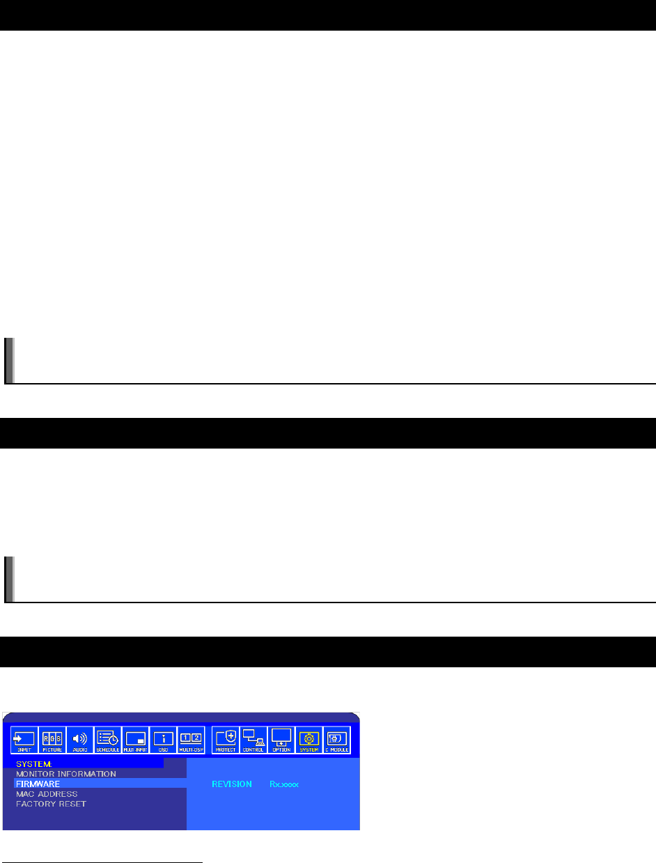
8.14 Checking and updating the display firmware version
The display firmware version is displayed on the SYSTEM FIRMWARE menu on the OSD.
2
These models require display firmware version R1.7 or later for this feature: P404, P484, P554, V404, V484, V554,
V404-T, V484-T, V554-T, C751Q, C861Q, C981Q, P754Q, V554Q, V754Q, V864Q, V984Q

©2019 NEC Display Solutions, Ltd. Page 44 of 74
The latest firmware can be downloaded from the following location:
http://www.nec-display.com/dl/en/dp_soft/pd_fm_update/index.html
Firmware can be updated via either a USB flash drive or the HTTP server in the display. See the
instructions located at the above location for details.
©2019 NEC Display Solutions, Ltd. Page 45 of 74
9 Related OSD Settings
9.1 Compute Module menu Power Power Supply
Available options: On / Off
Controls power to the Compute Module.
If the Shutdown Signal is Enabled, selecting Off will set the shutdown signal and the Power Supply Off
Delay timer will start. Power to the Compute Module will be turned off once the timer has finished.
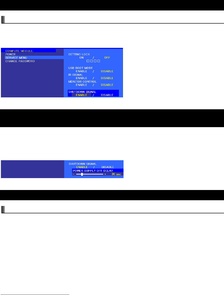
9.2 Compute Module menu Power Auto Power On
Available options: Enable / Disable
When set to Enable, power to the Compute Module will be turned on automatically when the display
power is turned on. If set to Disable, power to the Compute Module is manually controlled via either the
POWER SUPPLY setting on the COMPUTE MODULE OSD menu, or via the HTTP interface to the
display, or via a LAN command to the display (OpCode 117Ch).
Note that the Compute Module will remain on even when the display has been placed into Standby mode,
unless it is turned off via the POWER SUPPLY setting on the COMPUTE MODULE OSD menu, or via the
HTTP interface to the display, or via a LAN command to the display (OpCode 117Ch).
9.3 Compute Module menu Service Menu Setting Lock
Available options: On / Off
Access to other items on the SERVICE MENU is protected by a 4 digit password to prevent unauthorized
access. The password can be set on the Compute Module CHANGE PASSWORD OSD menu. The
default password is 0 0 0 0.
The Setting Lock will default to On.

©2019 NEC Display Solutions, Ltd. Page 46 of 74
9.4 Compute Module menu Service Menu USB Boot Mode
Available options: Enable / Disable
When set to Enable, the Compute Module will appear as a USB device to a PC connected to the USB2
input on the display and can be programmed with an Operating System. When set to Disable, the
Compute Module will boot normally. See chapter USB connections for programming the Compute Module
on page 16.
9.5 Compute Module menu Service Menu IR Signal
Available options: Enable / Disable
Enables or disables the forwarding of IR remote control signals, received from the display’s internal and
optional external IR sensor, to the Compute Module via GPIO 18.
See section 0 for more details on using this feature.
9.6 Compute Module menu Service Menu Monitor Control
Available options: Enable / Disable
Enables or disables the internal serial connection between the display and Compute Module. If set to
Enable, communications is available via GPIO 14 & 15. This GPIO will normally appear as a TTY device.
Make sure the Operating System doesn’t send boot console debug messages to the UART serial port; it
may cause erratic behavior in the display (such as the OSD flashing, random operations being performed,
slow bootup of the Compute Module, etc.).
©2019 NEC Display Solutions, Ltd. Page 47 of 74
9.7 Compute Module menu Service Menu Shutdown Signal
Available options: Enable / Disable
Enables or disables the use of GPIO 23 to signal that power to the compute module will be shutting down.
Note that a monitoring utility must be installed to watch the GPIO 23 shutdown signal and shut down the
operating system accordingly.
9.8 Compute Module menu Service Menu Shutdown Signal
Power Supply Off Delay
For use only when the Shutdown Signal is set to Enable. This sets the time delay after the Shutdown
Signal is set until the power to the Compute Module is turned off. Configure this to allow adequate time
for any software to shutdown safely. Note that a monitoring utility must be installed to watch the GPIO 23
shutdown signal.
9.9 Compute Module menu Service Menu WDT
Available options: Enable / Disable
Enables or Disables the display’s built in Watchdog Timer function for the Compute Module.
3
When set to Enable, the display will expect to receive a periodic reset command from the Compute
Module via the internal UART. If the command isn’t received for two consecutive timeout periods, the
display will restart the Compute Module.
This feature can be used to automatically reset the Compute Module if the CPU hangs for some reason.
The following two settings control the timeout periods: Start Up Time, Period Time
The Python SDK includes sample functions to send the periodic reset command. However, it is up to the
developer to configure the system to make sure this runs as the Compute Module starts and continues to
periodically send the reset command. See Python Based NEC PD SDK on page 65.
See section 7.11 for more details on using this feature.
3
These models require display firmware version R1.006E or later for this feature: P404, P484, P554, V404, V484,
V554, V404-T, V484-T, V554-T
©2019 NEC Display Solutions, Ltd. Page 48 of 74
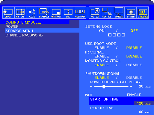
9.10 Compute Module menu Service Menu WDT Start Up
Time
For use only when the WDT is set to Enable.
4
This sets the time delay for when the display should start receiving WDT reset commands, via the
internal UART, after power is applied to the Compute Module.
This timer's value should be set high enough to include time for the operating system to fully load, on the
Compute Module, and for the periodic reset commands to begin sending to the display.
9.11 Compute Module menu Service Menu WDT Period Time
For use only when the WDT is set to Enable.
4
This sets the maximum amount of time within which the display must receive WDT reset commands from
the Compute Module, via the internal UART. If two consecutive reset commands are missed, the display
will restart the Compute Module.
This timer’s value should be set high enough to ensure that any software running on the Compute Module
will be able to send the periodic reset command to the display, even under heavy load conditions.
4
These models require display firmware version R1.006E or later for this feature: P404, P484, P554, V404, V484,
V554, V404-T, V484-T, V554-T
©2019 NEC Display Solutions, Ltd. Page 49 of 74
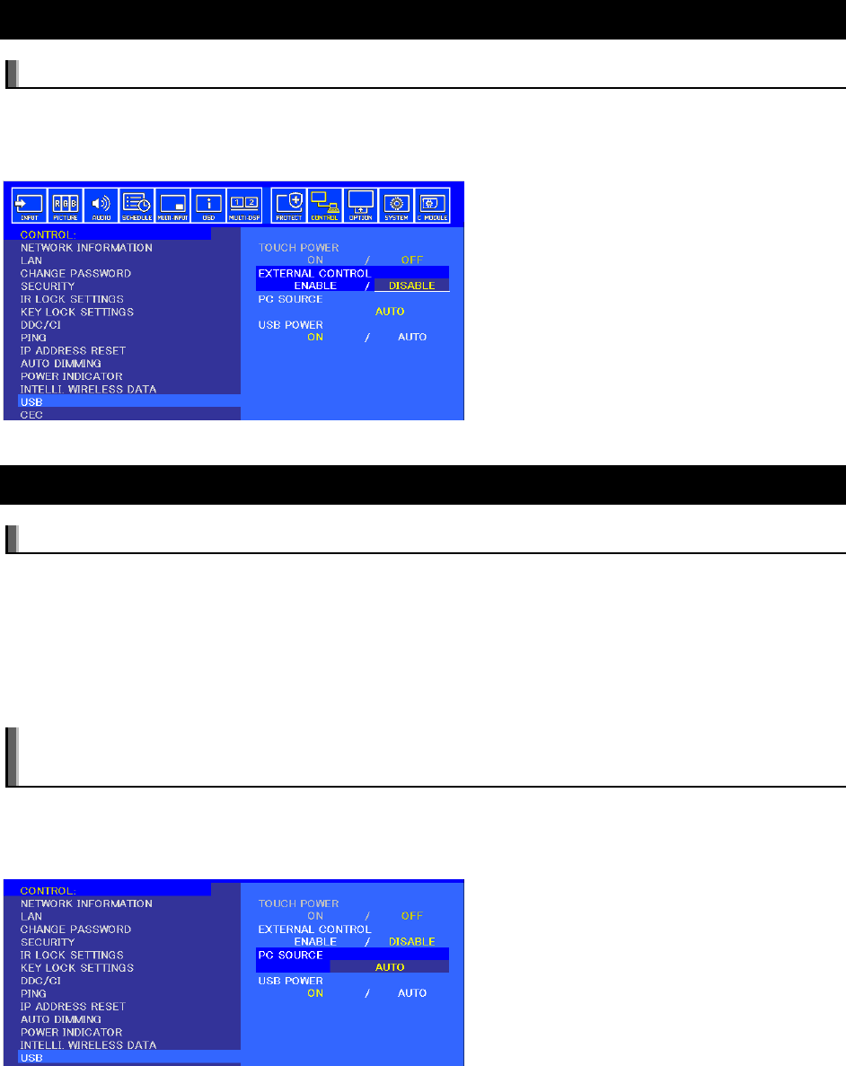
9.12 Control menu USB External Control
Available options: Enable / Disable
Enables or Disables monitor control via USB. Software such as NEC SpectraView and MultiProfiler use
the USB connection to the display for communications. This connection is shared between the External
PC, Internal PC (OPS), and the Compute Module, and it is switched using the following setting.
9.13 Control menu USB PC Source
Available options: Auto / Internal PC / External PC / C Module
Selects the routing of the USB1 input on the display. It also routes the internal USB connection from the
touch sensor on display models with an integrated touch-screen.
This setting can be switched between the Compute Module, Internal PC (OPS) (if installed), and an
External PC connected to the USB2 connection. By selecting Auto, it can be configured to switch
automatically depending on the currently selected video input. This allows devices such as a mouse to be
shared automatically between different sources as the video input is changed.
Note: Only the USB1 connection is switched. The USB CM1 and CM2 connections are dedicated to
the Compute Module.
For display models with an integrated touch-screen, the internal USB connection from the touch sensor
will also follow the PC SOURCE setting so that as video inputs on the display are changed, the touch-
screen connection will automatically switch to the correct source device.
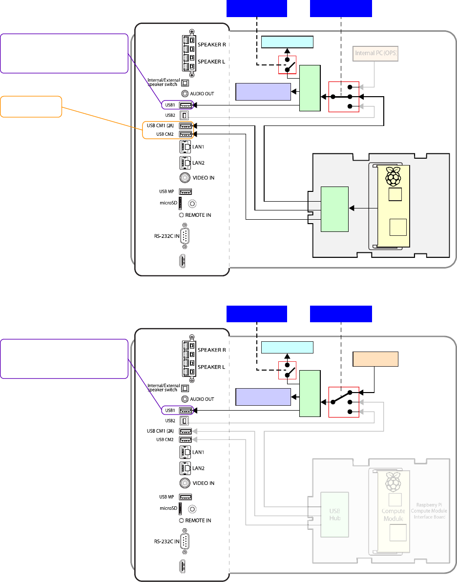
©2019 NEC Display Solutions, Ltd. Page 50 of 74
Figure 8.13-1: USB Routing with the Compute Module selected as the source
Figure 8.13-2: USB Routing with the Internal PC (OPS) selected as the source
Comput
e
Module
USB
Hub
Raspberry Pi
Compute Module
Interface Board
HDMI IN1
Internal PC(OPS)
ENABLE / DISABLE
MONITOR CONTROL
Internal Touchscreen
connection (option)
Display USBControl
USB
Hub
PC SOURCE
C MODULE
Dedicated to the
Compute Module
Shared between the Compute Module,
Internal PC (OPS), and External PC.
Controlled by the“PC SOURCE” setting
in “Control” ->“USB” on the OSD menu.
Compute
Module
USB
Hub
Raspberry Pi
Compute Module
Interface Board
HDMI IN1
Internal PC(OPS)
ENABLE / DISABLE
MONITOR CONTROL
Internal Touchscreen
connection (option)
Display USBControl
USB
Hub
PC SOURCE
INTERNAL PC
Shared between the Compute Module,
Internal PC (OPS), and External PC.
Controlled by the“PC SOURCE” setting
in “Control” ->“USB” on the OSD menu.
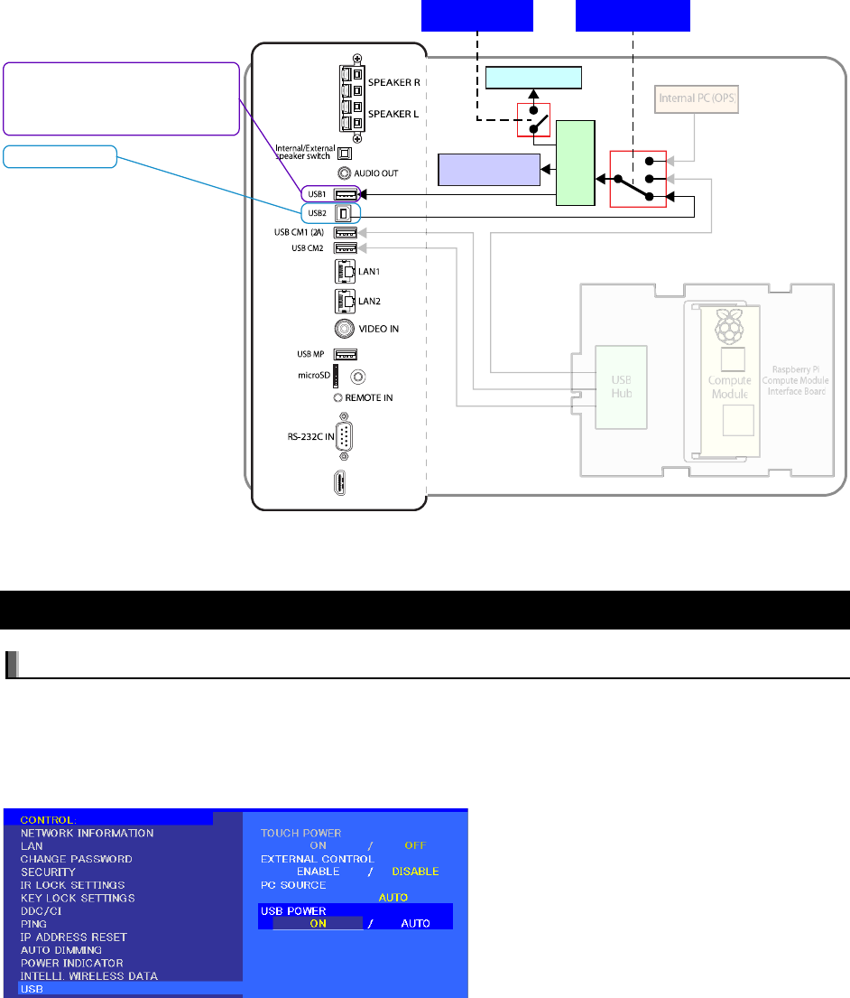
©2019 NEC Display Solutions, Ltd. Page 51 of 74
Figure 8.13-3: USB Routing with the External PC selected as the source
9.14 Control menu USB USB Power
Available options: On / Auto
Selects when power is supplied to the USB CM1 connection on the display. When set to Auto, power is
supplied only if the Compute Module and Compute Module Interface Board are installed in the display.
When set to On, power is supplied at all times even when the display is in standby mode.
The USB CM1 connection is capable of supplying up to 2.0A.
Comput
e
Module
USB
Hub
Raspberry Pi
Compute Module
Interface Board
HDMI IN1
Internal PC(OPS)
ENABLE / DISABLE
MONITOR CONTROL
Internal Touchscreen
connection (option)
Display USBControl
USB
Hub
PC SOURCE
EXTERNAL PC
Shared between the Compute Module,
Internal PC (OPS), and External PC.
Controlled by the“PC SOURCE” setting
in “Control” ->“USB” on the OSD menu.
External PC input
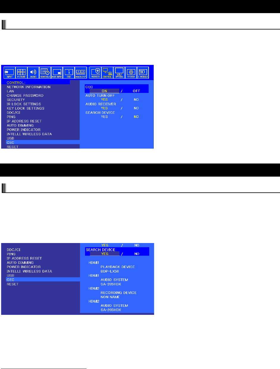
©2019 NEC Display Solutions, Ltd. Page 52 of 74
9.15 Control menu CEC CEC
Available options: On / Off
Enables and disables the CEC (Consumer Electronics Control) function between the display and the
Compute Module, in order to control CEC enabled software via the display’s IR Remote Control.
5
See section 0 for more details on using this function.
9.16 Control menu CEC Search Device
Available options: Yes / No
Selecting Yes will start the process of the display searching for a CEC (Consumer Electronics Control)
device on the connection to the Compute Module. If no device is found, confirm that CEC enabled
software is currently running on the Compute Module and that any CEC device drivers are enabled.
5
Once the device has been detected, the display’s IR Remote Control can be used to navigate and control
CEC enabled software.
5
These models require display firmware version R1.006E or later for this feature: P404, P484, P554, V404, V484,
V554, V404-T, V484-T, V554-T
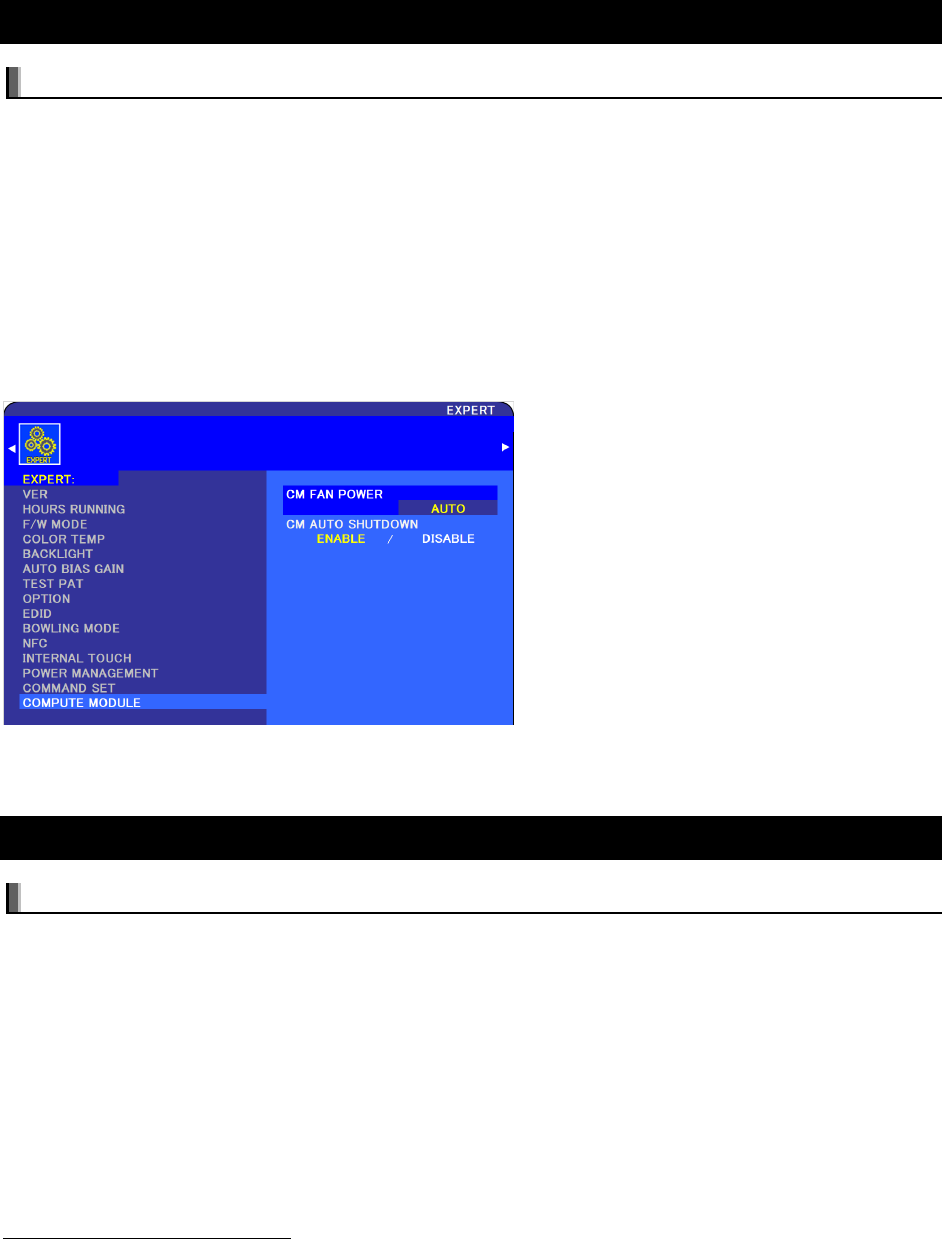
©2019 NEC Display Solutions, Ltd. Page 53 of 74
9.17 Expert menu Compute Module CM Fan Power
Available options: Auto / On / Off
Selects the operating mode of the Compute Module cooling fan.
• Auto (Default) - The display automatically turns the cooling fan on and off when the Compute
Module is powered on and off.
• Off - Immediately turns the cooling fan off. The fan will remain off even when power to the
Compute Module is turned on.
• On - Immediately turns the cooling fan on. The fan will remain on even when power to the
Compute Module is turned off.
This setting is available via the Expert menu and as a command to the display (OpCode 0x11B5).
6
9.18 Expert menu Compute Module CM Auto Shutdown
Available options: Enable / Disable
Selects how power to the Compute Module is handled when the display is turned off.
• Enable – When the display is turned off, power to the Compute Module will also be turned off. If
SHUTDOWN SIGNAL is enabled, this will be performed first to allow the system to gracefully
shut down before power is removed.
• Disable (Default) – Power to the Compute Module will remain on even when the display is
turned off.
This setting is available via the Expert menu and as a command to the display (OpCode 0x11B7).
6
6
These models require display firmware version R1.7 or later for this feature: P404, P484, P554, V404, V484, V554,
V404-T, V484-T, V554-T
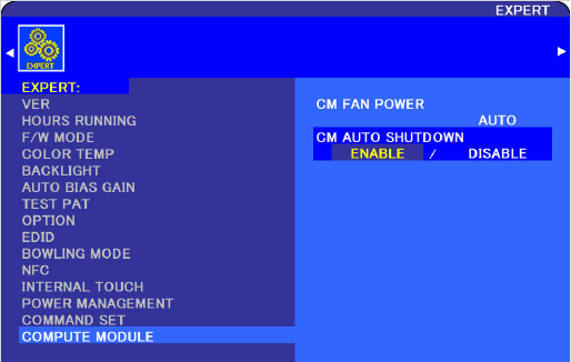
©2019 NEC Display Solutions, Ltd. Page 54 of 74

©2019 NEC Display Solutions, Ltd. Page 55 of 74
10 Useful Information and Commands
10.1.1 To find out the IP address of the Compute Module from a terminal window
Use the following command from a terminal window:
hostname –I
Or
ifconfig
10.1.2 To restart from a terminal window
Use the following command:
sudo reboot
10.1.3 To shutdown from a terminal window
Use the following command:
sudo shutdown -h now
10.1.4 To run the Raspberry Pi Config utility from a terminal window
Use the following command:
sudo raspi-config
10.1.5 To change the keyboard layout to US from a terminal window
Either
• Use the following command
setxkbmap us
Or
• Use the following command and select “Internationalization Options”
sudo raspi-config
Select: 5 Internationalization Options
Select: I3 Change Keyboard Layout
Enter
©2019 NEC Display Solutions, Ltd. Page 56 of 74
Note: It may take several seconds for the list to appear.
Select: English (US)
Enter
Enter
Select: Finish
Or
• Edit the keyboard configuration file manually
sudo nano /etc/default/keyboard
Change the following line
XKBLAYOUT=”gb”
to
XKBLAYOUT=”us”
10.1.6 To add and remove packages from Raspbian
To add (install) a package:
sudo apt-get install [packagename]
To remove (uninstall) a package:
sudo apt-get remove [packagename]
For more information visit:
https://www.raspberrypi.org/documentation/linux/software/apt.md
10.1.7 To update the Raspberry Pi
To update the current OS version:
sudo apt-get update
To update the current software packages installed:
sudo apt-get upgrade
To update the current Raspberry Pi firmware:
sudo rpi-update
Note: The Compute Module’s ‘firmware’ is stored in a file on the filesystem and can thus be
transferred if the flash memory is re-imaged to another Compute Module device.

©2019 NEC Display Solutions, Ltd. Page 57 of 74
10.1.8 To install the Python serial module
To install the Python serial module necessary for internal communications with the display.
From Raspbian use:
sudo apt-get install python-serial
10.1.9 To mount a USB flash drive from the terminal
Example:
sudo mkdir /media/usbstick
sudo mount –t vfat –o uid=pi,gid=pi /dev/sda1 /media/usbstick
Replace “sda1” if drive devices is located in another location such as “sdb1”.
10.1.10 To access an SMB (Windows share) drive from the Raspbian desktop
Open a File Manger window. Enter a path into the location bar in the following format:
smb://sharename/foldername
Where “sharename” is the name of the host and “foldername” is the name of the folder being shared.
10.1.11 To list connected USB devices
From Raspbian use:
lsusb
10.1.12 To show available disk space
From Raspbian use:
df -h

©2019 NEC Display Solutions, Ltd. Page 58 of 74
10.1.13 To show internal information about the Raspberry Pi
From Raspbian use the following to list all available commands:
vcgencmd commands
Examples:
Show the internal temperature:
vcgencmd measure_temp
Show configurations that have been set:
vcgencmd get_config int
Information about the Raspberry Pi hardware including the processor’s serial number:
cat /proc/cpuinfo
10.1.14 To download a file to the current directory
From Raspbian use:
wget http://www.website.com/example.txt
10.1.15 To find a file by name
From Raspbian use:
find / -name example.txt
10.1.16 To edit a protected system configuration file from the Raspbian
desktop
From a terminal window open the Leafpad editor as sudo:
sudo leafpad
The file can now be opened, edited, and saved.
10.1.17 To install a minimal windowing system on Jessie Lite
From the command prompt enter the following command:
sudo apt-get install --no-install-recommends gvfs raspberrypi-ui-mods
xserver-xorg-video-fbturbo lxterminal

©2019 NEC Display Solutions, Ltd. Page 59 of 74
10.1.18 To prevent the screen saver from blanking the screen after several
minutes
From the Raspbian edit the following file as sudo: /etc/lightdm/lightdm.conf
Modify the following section to add the highlighted text:
[SeatDefaults]
xserver-command=X -s 0 –dpms
10.1.19 To enable IR Remote control using CEC from OSMC
Navigate to: Settings System Input Peripherals CEC Adapter
Enable the setting. A restart may be required before the CEC device can be detected by the display.
Use the supported CEC buttons on the NEC IR Remote. See Figure 3.4-3.
See sections 0, 8.15 and 8.16 for more information.
Note: Information as of OSMC version 2017.02-2
10.1.20 To enable IR Remote control using lirc from OSMC
Navigate to: My OSMC Remotes.
Scroll to the correct IR remote type or “lircd-full” and select.
Make sure that “Disable RC6” on the bottom right isn’t selected.
Navigate to: My OSMC Pi Config Hardware support.
Select “Enable LIRC GPIO support”.
The use the default of gpio_in_pin = 18.
A restart may be required before lirc can be started.
See section 0 and 8.5 for more information.
Note: Information as of OSMC version 2017.02-2
10.1.21 Monitoring the system processes, CPU usage, and memory
The htop system tool is an interactive system-monitor process-viewer and process-manager that gives
visual information about processor, swap and memory status. Run from the command or terminal window:
htop

©2019 NEC Display Solutions, Ltd. Page 60 of 74
10.1.22 To enable and disable video output from the Compute Module to the
display
The internal HDMI video signal from the Compute Module to the display can be disabled and enabled
using the following commands. This can be useful for example to cause the display to enter standby
mode or switch to another video input via the loss of video from the Compute Module, depending on the
display settings.
To disable (turn off) the HDMI video signal output:
vcgencmd display_power 0
To enable (turn on) the HDMI video signal output:
vcgencmd display_power 1

©2019 NEC Display Solutions, Ltd. Page 61 of 74
11 Troubleshooting
Problem: No video when switching to the Compute Module input
Solutions:
• Confirm the Compute Module and Compute Module Interface board are correctly installed.
• On the COMPUTE MODULE menu of the OSD, confirm that POWER SUPPLY is set to ON.
• On the COMPUTE MODULE menu of the OSD, confirm that USB BOOT MODE is set to DISABLE.
Note: The Compute Module power will have to be cycled off and on after changing the boot
mode to DISABLE.
• Confirm that a valid OS image has been written to the Compute Module.
Problem: Compute Module hangs at the rainbow screen
Solutions:
• The imaged OS may not include support for the Compute Module model being used.
• Confirm that the image includes the correct corresponding file:
•
bcm2708-rpi-cm.dtb - for the Compute Module 1
•
bcm2710-rpi-cm3.dtb - for the Compute Module 3
Confirm the Compute Problem: Screen appears gray and blacks aren’t true black.
Solution:
• Most OS distros on the Compute Module are set to output the video range of 16 to 235
(otherwise known as “RGB limited”) by default.
• Make sure the display settings for handling the video levels from the Compute Module match
those on the OSD settings of the display. See the “Configuring the correct HDMI video level
encoding and decoding” section for more details.
Problem: Black borders appear around the screen image
Solution:
• Overscan needs to be disabled. Follow the previous instructions for checking the
“
disable_overscan=1” configuration setting in the config.txt file.

©2019 NEC Display Solutions, Ltd. Page 62 of 74
Problem: “RPi Boot” is unable to detect the Compute Module
Solutions:
• If the display is currently in a power save mode (LED is flashing green), press the POWER ON
button on the IR Remote control.
• On the COMPUTE MODULE menu of the OSD, confirm that POWER SUPPLY is set to ON.
• On the COMPUTE MODULE menu of the OSD, confirm that USB BOOT MODE is set to ENABLE.
Note: The Compute Module power will have to be cycled off and on after changing the boot
mode to ENABLE.
• Check that the Compute Module is correctly seated and latched in the SO-DIMM socket on the
Interface board.
• Check that a USB cable is connected from the USB2 connector on the display to the host PC.
• Do not use a USB extender cable or hub between the host PC and the display. The host PC must
be directly connected to the display via a single USB cable.
• “RPi Boot” may have already been run while the Compute Module has been powered up in boot
mode. Running it again will not find the Compute Module.
• Disconnect and reconnect the USB cable to the host PC.
Problem: 3
rd
party IR Remote is not functioning
Solutions:
• Confirm the OSD COMPUTE MODULE setting for IR SIGNAL is set to ENABLE
• Confirm lirc is enabled in the
config.txt file.
• Confirm the software being used is correctly configured for the 3
rd
party remote.
• Use lirc debugging mode to view the raw IR sensor output.
• CEC support may be enabled. Normally CEC support must be disabled in order for lirc to work
correctly.
Problem: Serial communications with the display not functioning
Solutions:
• Confirm the OSD COMPUTE MODULE setting for MONITOR CONTROL is set to ENABLE
• Confirm the
config.txt file contains the following line:
enable_uart=1
If using the Compute Module 3, the following two lines are also necessary:
dtoverlay=uart1
core_freq=250

©2019 NEC Display Solutions, Ltd. Page 63 of 74
• Confirm the cmdline.txt file doesn’t contain any sections with “console=serial0…..” or
“console=ttyAMA0,…….”.
• Confirm no other software is currently accessing the serial port.
Problem: The Compute Module continually restarts
Solution:
• Confirm the OSD COMPUTE MODULE setting for WDT (Watchdog Timer) is set to DISABLE or, if
set to ENABLE, that any watchdog timer function installed is correctly configured to reset the
timer in the display within the TIME PERIOD set on the OSD.
Problem: Flashing the Compute Module fails after a couple of minutes.
Solution:
• Confirm the OSD COMPUTE MODULE setting for WDT (Watchdog Timer) is set to DISABLE.
Problem: Video playback is slow or jerky
Solutions:
• The default of 64 MB for video may not be enough for full-screen video. Try allocating at least
128 MB system memory as video memory. 192 MB is recommended if for full-screen playback
of 1920x1080 video files.
o Using the Raspberry Pi Config Utility from a terminal window:
sudo raspi-config
Select: 7 Advanced Options
Select: A3 Memory Split
Change to at least 128
Save and restart the system.
o By editing the config.txt file:
Modify or add this line if it doesn’t already exist:
gpu_mem=128
Save and restart the system.

©2019 NEC Display Solutions, Ltd. Page 64 of 74
12 Codec Licenses
License keys for the hardware MPEG-2 and VC-1 codecs are included with the custom 16GB Raspberry
Pi Compute Module 3 NEC Edition. The licenses are programmed into the processor during production. It
is not necessary to purchase license keys.
All Compute Modules include hardware codec support for MPEG-4.
For the standard Compute Module 1 and 3, license keys for the MPEG-2 and VC-1 codecs can be
purchased from Raspberry Pi and added to the config.txt file for the following section:
# License Keys
decode_MPG2=
decode_WVC1=
Support for individual codecs can be confirmed using the following commands in a terminal window:
vcgencmd codec_enabled MPG2
vcgencmd codec_enabled MPG4
vcgencmd codec_enabled WVC1

©2019 NEC Display Solutions, Ltd. Page 65 of 74
13 Python Based NEC PD SDK
NEC has created a Python based SDK (Software Development Kit) to support many of the monitor
functions easily via the Operating System running on the Compute Module.
Examples of supported functions are:
• Reading status information from the display, such as:
o Model name
o Serial number
o Temperature and fan statuses
o Diagnostic information
o Operating hours
o LAN IP and MAC addresses
This makes it very easy to integrate support for remote diagnostics and asset management into
any software running on the Compute Module.
• Reading and writing almost any configuration setting and control within the display, such as:
power, video settings, schedules, Picture-in-Picture, Tile Matrix, etc.
This can be used to easily configure or reset settings via remote using a script.
• Accessing the display’s internal Real Time Clock. This can be used to set the Operating System’s
clock when it is unable to get the current time from the network.
• Monitoring the Shutdown signal from the display on GPIO 23 to gracefully shutdown any
running software and the Operating System, before the display turns off power to the Compute
Module.
• To periodically send reset commands to the display’s built in Watchdog Timer, to signal that the
Operating System is currently running correctly. The lack of a reset signal would indicate that
the CPU on the Compute Module is hung, and the display would automatically restart the
Compute Module.
• Automatically control the cooling fan for the Compute Module based on the reported system
temperature on the Compute Module’s internal temperature. This is done by sending a
command to the display to control the fan power.
Note: This feature requires at least display firmware version R1.7 on the Pxx4 and Vxx4/-T
models.
Communications with the display is via the UART on the Compute Module and an internal serial
connection to the display. It is also possible to communicate with the display over LAN via its IP address.
The SDK supports both communicating via both serial and LAN.
The SDK provides APIs (Application Programming Interfaces) for most of the commands supported by
the display, so it is not necessary to start understanding the communications protocol from scratch.
However, it is highly recommended to refer to the “External Control” document for the model being used
to understand the parameters and function of each API.
The SDK can be installed from Raspbian using either of the following commands:
sudo easy_install nec_pd_sdk

©2019 NEC Display Solutions, Ltd. Page 66 of 74
or
sudo –H pip install nec_pd_sdk
It can also be downloaded or cloned from the repository on GitHub:
https://github.com/NECDisplaySolutions/necpdsdk
Example files are included in the repository. These examples are not included in the package installer.
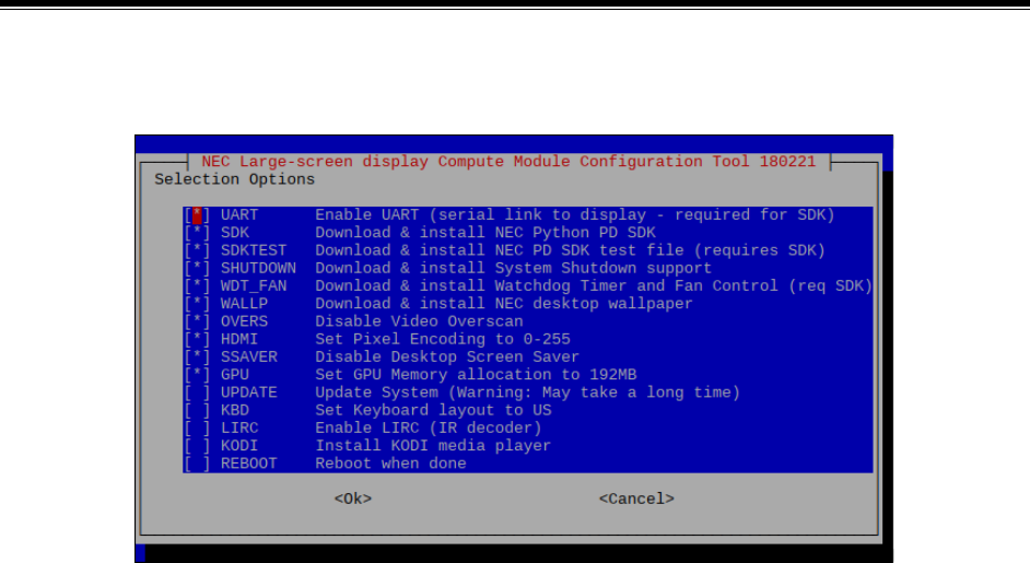
©2019 NEC Display Solutions, Ltd. Page 67 of 74
14 Compute Module Configuration Tool for Raspbian
NEC has created a menu based tool for automatically downloading and configuring various components
and settings for Raspbian OS on the Raspberry Pi Compute Module. This makes it easy to configure a
new OS install.
Options include:
• Configuring the UART to allow communications with the host display.
• Downloading and installing the NEC Python PD SDK which provides APIs for communicating with
the host display. It will also install the Python Serial module if necessary.
• Downloading and installing an example Python file showing how to use the SDK APIs to
communicate with the host display.
• Downloading and installing a Python file that provides System Shutdown support by monitoring
GPIO 23 - set low by the display to signal a shutdown.
• Downloading and installing a Python file that provides hardware based Watchdog Timer support
and automatic cooling fan control by the host display.
• Downloading and installing NEC branded desktop wallpaper.
• Disabling Video Overscan.
• Setting the HDMI Pixel (video level range) Encoding to 0-255.
• Disabling the Desktop Screen Saver to prevent screen blanking.
• Setting the GPU Memory allocation to 192MB.
• Updating the operating system and firmware.
• Setting the Keyboard layout to "US".
• Enabling the LIRC (IR decoder) support.
• Installing the KODI media player with remote control using the display's IR remote.
• Installing the Yodeck bootloader.
This can be downloaded from:


©2019 NEC Display Solutions, Ltd. Page 69 of 74
15 External reference information
Main Raspberry Pi website:
https://www.raspberrypi.org/
Wikipedia page with listing of other supported operating systems:
https://en.wikipedia.org/wiki/Raspberry_Pi#Operating_systems
Another listing of Raspberry Pi based operating system distributions:
http://elinux.org/RPi_Distributions
Generic information for flashing the Compute Module:
https://www.raspberrypi.org/documentation/hardware/computemodule/cm-emmc-flashing.md
Information on using raspi-config:
https://www.raspberrypi.org/documentation/configuration/raspi-config.md
Information on using VNC to remotely control the desktop interface from another machine:
https://www.raspberrypi.org/documentation/remote-access/vnc/README.md
Accessing CEC (IR remote) functionality using Python via the libcec library:
https://github.com/Pulse-Eight/libcec/blob/master/src/pyCecClient/pyCecClient.py

©2019 NEC Display Solutions, Ltd. Page 70 of 74
16 Frequently Asked Questions
What video resolutions are recommended and supported?
Using the native resolution of 1920x1080 is recommended. Other resolutions may work.
Is the Raspberry Pi Compute Module functionality limited in some way, such as what software or
Operating Systems can be used?
No.
Are the GPIO pins on the Compute Module accessible and open to use?
Currently the header on the NEC Compute Module Interface board is not populated and not supported.
What is the communications speed of the internal serial connection to the display?
9600 baud. No parity. 8 bits data length with 1 stop bit.
What are the differences between the Raspberry Pi Compute Module 3 NEC Edition and the
standard Compute Module?
The Raspberry Pi Compute Module 3 NEC Edition includes 16GB of eMMC onboard storage instead of
the standard 4GB. The NEC edition also includes codec licenses for the MPEG-2 and VC-1 hardware
codecs. These licenses are programmed into the processor during production and do not need to be
included in the config.txt file. Note that the CM3+ is available from RaspberryPi in 8, 16 and 32GB
capacities.
Does NEC provide support for any software or Operating System on the Compute Module?
NEC provides a Python based SDK for accessing the monitor control functionality via the internal serial
connection. Support for other software or Operating Systems are not provided by NEC. See Python
Based NEC PD SDK on page 65.
Does the Compute Module 3 provide any support for Wi-Fi or Bluetooth?
All included network connectivity is via the LAN connections on the display. Wi-Fi and Bluetooth
connectivity can be added by using a 3
rd
party USB dongle connected to the display.

©2019 NEC Display Solutions, Ltd. Page 71 of 74
Does the NEC Compute Module Interface board provide SD card support to use instead of the
onboard eMMC memory?
No.
Can the video output of the Compute Module be daisy-chained to another display via the Display
Port Output connection?
No.
Can the microSD slot be used to expand the onboard memory of the Compute Module?
No. The microSD slot, as well as the USB MP input, are dedicated to the internal Media Player on the
display and cannot be used by the Compute Module. The USB CM1 and USB CM2 inputs can be used to
connect additional USB based storage dedicated for the Compute Module.
Is it possible to run Android OS on the Compute Module?
There are currently some experimental builds of Android for the Raspberry Pi; however, these are
probably not stable enough to be used for professional and commercial applications, and may not even
work at all on the Compute Module version of the Raspberry Pi.
NEC currently recommends using the OPS Android DRD Digital Signage Player instead.
Does the NEC Compute Module provide support for Wi-Fi or Bluetooth?
No. However, a universal USB dongle such as the one on the Raspberry Pi site can be connected to the
USB port on the display.
Is it possible to boot directly to an external USB drive instead of the onboard eMMC memory?
No.
Warning: Do not attempt to set the USB boot mode flag in the Compute Module’s OTP by using
program_usb_boot_mode=1. Setting this will render the Compute Module permanently unable to
enter USB Boot Mode while hosted within the display. Flashing of the device via USB will no longer be
possible.

©2019 NEC Display Solutions, Ltd. Page 72 of 74
What is the MAC address of the Compute Module?
The MAC address is assigned by the Compute Module itself and is derived from the CPU serial number.
The first 3 octets (B8:27:EB) are fixed and assigned to Raspberry Pi Foundation. The remaining 3 octets
are the last 6 hex digits of the CPU serial number. For example, if the CPU serial number is
0000000096bf4e08 the MAC address will be B8:27:EB:BF:4E:08. The CPU serial number can be
obtained by using:
cat /proc/cpuinfo
How long does it take to flash the Compute Module?
It depends on the size of the image being flashed. USB read and write speeds are typically 5MB/s. So a
4GB image will take approximately 13 minutes to write. That time will double if verification is used. Using
the Etcher flashing software can speed up the process significantly.
How can I find out the LAN IP or MAC address of the host display from the Compute Module?
The Python SDK includes the functions command_ip_address_read() and
command_lan_mac_address_read() that will return the IP and MAC address of the display.
How can the Compute Module be automatically shut down when the display is turned off?
A new Expert mode control has been added to the OSD that will enable performing a shutdown of the
Compute Module when the display is turned off via a command, power button, OSD menu, or IR remote
control. See CM Auto Shutdown in section 8.18
Are the NEC displays compatible with the new Compute Module CM3+?
The 8, 16, and 32 GB eMMC versions are supported.
Are the NEC displays compatible with the Compute Module Lite?
No. The CM Lite requires SD card support.

©2019 NEC Display Solutions, Ltd. Page 73 of 74
17 Known Issues
Display Firmware
• Shutting down the Compute Module via the HTTP interface and OpCode 117Ch is not working
correctly in firmware prior to R1.006E on the Pxx4 and Vxx4/-T displays.
• CEC (Consumer Electronics Control) support between the display and Raspberry Pi Compute
Module requires at least firmware R1.006E on the Pxx4 and Vxx4/-T displays.
• Watchdog Timer support for the Compute Module requires at least firmware R1.006E on the
Pxx4 and Vxx4/-T displays.
Compute Module 3
• Some older OS distros may not include the boot firmware for the Compute Module 3 and may
fail to start correctly (hang at the rainbow start screen). Confirm that the OS being used is the
correct version and build for the Compute Module being used.

©2019 NEC Display Solutions, Ltd. Page 74 of 74
18 Support
For more general support on the Raspberry Pi, Raspbian OS, and the Compute Module, it is
recommended to visit the support forums at the Raspberry Pi Foundation:
https://www.raspberrypi.org/forums/
The latest version of this document, additional information, downloads, and feedback forms specifically
relating to using the Raspberry Pi Compute Module together with a supported NEC display model are
available here:
http://www.necdisplay.com/support-and-services/raspberry-pi/
The latest display firmware is available from the following location:
http://www.nec-display.com/dl/en/dp_soft/pd_fm_update/index.html
