
ESP8266 IoT Workshop
using a DHT11/22 and NeoPixel RGB LED with data analysis on the IBM
Cloud
Brian Innes
None

Table of contents
- 2/145 -

Table of contents
Table of contents
- 3/145 -

61. Real World IoT with the ESP8266
61.1 Welcome to the ESP8266 IoT Workshop
61.2 Navigation
61.3 Access to workshop material
61.4 Typical agenda for a workshop day
61.5 Course outline
82. Part 1
82.1 Part 1
92.2 Installing the prerequisite software and getting your cloud account setup
132.3 Your first ESP8266 application
152.4 Connecting the ESP8266 to a WiFi network
172.5 Controlling the RGB LED from the ESP8266
222.6 Reading the DHT Sensor from the ESP8266
262.7 Deploying an application to the IBM Cloud
333. Part 2
333.1 Part 2
343.2 Registering a new device to the Watson IoT Platform
363.3 Creating the sensing application for the ESP8266
393.4 Connecting Device to the Watson IoT Platform using MQTT
443.5 Adding secure communication between the device and IoT Platform using SSL/TLS
523.6 Using a Device Certificate to authenticate to the Watson IoT platform
584. Part 3
594.1 Part 3
614.2 Node-RED Set up and Configuration in IBM Cloud
674.3 Receive Device Environmental Sensor Data in Node-RED
754.4 Node-RED Dashboard Charts - Plot Environmental Sensor Data
844.5 Store Data in Cloud Storage for Historical Data Analytics
894.6 Node-RED Charts of Historical Sensor Data
914.7 Control your Device reporting interval via a Node-RED Dashboard Form
964.8 Control your Device LED Colors via Node-RED
995. Part 4
995.1 Part 4
1005.2 Watson Studio Set up and Configuration in IBM Cloud
1075.3 Create training data
1155.4 Run a Jupyter Notebook in Watson Studio
1245.5 Run the model on the ESP8266 device
1295.6 Workshop Summary
Table of contents
- 4/145 -


1. Real World IoT with the ESP8266
1.1 Welcome to the ESP8266 IoT Workshop
IoT workshop based on ESP8266, a DHT11/22 and NeoPixel RGB LED with data analysis on the IBM Cloud.
1.1.1 Stream Environmental Conditions to The Cloud
Learn how to connect an ESP8266 to the IBM Internet of Things (IoT) Platform over MQTT and stream environmental data from the sensors to the IBM
Cloud.
Workshop attendees will learn about ESP8266 programming, IoT Security, MQTT, IoT Platform, Node-RED, cloud storage, data analytics and visualisation
techniques.
1.2 Navigation
To move through the workshop you can use the side panels to select a specific section or use the navigation links at the bottom of each page to move to the next
or previous section as required.
1.3 Access to workshop material
The source for this workshop is hosted on GitHub and this site is automatically generated from the Markdown in the GitHub repository.
There is also a downloadable PDF containing the workshop instructions available here. The pdf is also linked at the bottom of each page.
1.4 Typical agenda for a workshop day
This workshop works well as a face-to-face workshop taking the majority of a day. A typical agenda can be seen here.
To help the flow of a face to face event having the prerequisite software installed can be helpful.
1.5 Course outline
1.5.1 Part 1
Provides an overview to the course, introduces the hardware, the development tooling and then gets you programming the ESP8266 device to connect to the local
WiFi network and be able to control the hardware. Part 1 finishes with an overview of the IBM Cloud, the cloud platform used in this workshop and ensures you
have a working cloud account with the required resources.
1.5.2 Part 2
The second part of the workshop looks at the Internet of Things service on the IBM Cloud and how you connect a device to the IBM Cloud using the MQTT
protocol. This section also looks at ensuring you have a secure connection between the device and the Cloud Platform, using SSL/TLS security and certificates.
1.5.3 Part 3
In this section we look at using a low-code development environment called Node-RED on the IBM Cloud to implement the server side part of the IoT solution.
You will create a dashboard to visualise the IoT data and also provide controls to configure the ESP8266 device. Your server side application will also control the
LED attached to the ESP8266.
1. Real World IoT with the ESP8266
- 6/145 -

1.5.4 Part 4
The last part of the workshop looks at how useful information can be extracted from the IoT data using analytics. You will be introduced to the Analytic services
available on the IBM Cloud and the tooling the services provide to help you extract useful information from sensor data.
Timing of the day can be found in the agenda
We've provided all the links used throughout the workshop as well as links to other resources here to help you explore a little more about IoT.
1.5.4 Part 4
- 7/145 -

2. Part 1
2.1 Part 1
Before you can start working on this workshop you need to have some prerequisite software installed and have a working account on the IBM Cloud. Details of
how to get setup can be found on the prerequisites page
2.1.1 Setup for the workshop
This section will take you through installing the prerequisite software on your machine and also ensuring you have the necessary accounts created.
Estimated duration: 15 min
practical Prerequisite Install and setup
2.1.2 Introduction to the ESP8266
This Lab will show you how to use the Arduino IDE with the ESP8266 plugin to create a new application for the ESP8266 board.
Estimated duration: 10 min
practical First App on ESP8266
2.1.3 ESP8266 WiFi connectivity
This Lab will show you how to connection your ESP8266 to a local WiFi network. This Lab will also introduce the Serial Monitor, which allows you to see output
from a running application.
Estimated duration: 15 min
practical WIFI scanning and connectivity
2.1.4 LED Light - sample app
In this Lab you will connect the NeoPixel LED and learn how to control it from the ESP8266.
Estimated duration: 15 minutes
practical RGB LED
2.1.5 DHT Temp - sample app
In this lab you will learn how to connect the DHT temperature and humidity sensor to the ESP8266 board and how to access data from the sensor.
Estimated duration: 15 minutes
practical DHT Sensor
2.1.6 IBM Cloud Internet of Things
In this lab you will learn how to deploy a starter application to the IBM Cloud.
Estimated duration: 10 minute
practical IoT deploy
•
•
•
•
•
•
•
•
•
•
•
•
2. Part 1
- 8/145 -

2.2 Installing the prerequisite software and getting your cloud account setup
2.2.1 Lab Objectives
This Lab will ensure you have all the resources and software needed to complete the lab installed. You should follow the instructions for your OS and complete
all sections of the setup before moving forward with the Lab.
2.2.2 ESP8266 development
To be able to complete the workshop you need to purchase the required hardware and install the required software to your laptop or workstation. You also need an
active IBM Cloud account and a suitable WiFi environment:
WiFi
The ESP8266 can connect to a 2.4GHz network supporting 802.11 b/g/n. The ESP8266 will not work with 5GHz frequencies (802.11 ac).
As there is no ability to launch a browser on the ESP8266, so you cannot work with WiFi networks needing a browser to be able to enter credentials, which is a
mechanism often used in public spaces, such as hotels.
The workshop does not support advanced authentication, such as using LDAP or certificates to authenticate to the network. You should have a network that uses
an access token/password, such as WPA/WPA2 - this is what most home WiFi access points provide.
Many corporate networks are difficult to connect IoT devices to, as they can be tightly secured, often requiring certificates to be installed.
If a suitable network is not available then smart Phone hotspots can be used to provide connectivity. The workshop does not require large amounts of data for the
ESP8266, so is suitable for using a phone hotspot.
There are no incoming ports needed for the workshop, but the ESP8266 needs to be able to connect via MQTT protocol over TCP to ports 1883 and 8883. The
workshop also need web access over TCP ports 80 and 443. The final port that is needed is for Network Time Protocol (NTP), which uses an outbound UDP
connection on port 123.
Purchasing the required Hardware
You need to purchase the following hardware to work through the workshop. The workshop instructions uses the DHT11 temperature and humidity sensor. This can
be replaced with the DHT22 sensor, which has the same pinout, but offers a more accurate sensor. DHT11 is accurate within 2C, whilst the DHT22 is accurate to
within 0.5C.
ESP8266, (search for NodeMCU ESP8266 v3 or v2)
NeoPixel RGB LED (or any other chainable RGB/RGBW LED based on ws2812b or sk6812 chips ), such as this from Adafruit (Search for Neopixel 8mm
or 5mm - often sold in packs of 5)
DHT11 Temperature / Humidity Sensor (search for DHT11 or DHT22)
6 x Female to Female jumper wires (search for dupont cable f2f or f-f - usually sold in packs of 40 cables)
MicroUSB cable (Please ensure it is a data cable, not just a power cable)
2.2.3 Installing the required software
The following instructions have been tested against Linux (Ubuntu 18.04LTS and Fedora 27), MacOS (High Sierra) and Windows 10. If you are using a different
OS then you may need to adapt the instructions to match your installed OS.
You may need admin access to your workstation to be able to install the software and drivers.
Step 1 - Install the required drivers
If you are attending an IBM face-to-face workshop, then the boards you will be using are branded LoLin and use the CH340 USB to serial chip.
•
•
•
•
•
2.2 Installing the prerequisite software and getting your cloud account setup
- 9/145 -
You may need a driver for your OS to be able to communicate with the USB to serial CH340G chip used in the ESP8266 modules. Do not plugin the device until
you have installed the driver on Windows and Mac. The drivers can be downloaded from :
MacOS (This is the manufacturers web site, in Chinese, for the USB driver chip on the LoLin NodeNCU board - use Google Chrome to translate, or just
click the download link to access the macOS driver). After installing goto System Preferences -> Security and Privacy to allow the driver to be loaded.
Alternatively if you use homebrew you can install the driver using command
Win/Linux
Select the appropriate one for your OS, download it, unzip it and install it.
If you have your own ESP8266 module then it may not use the CH340G USB to serial chip. Another very popular chip is the CP2102, which is used in Amica
branded boards. The drivers for this chip can be found here.
If you are a Mac user and use homebrew then the driver can be installed using command:
On Mac after the install you may need to approve the driver. From the Apple menu, go to System Preferences -> Security and Privacy to allow the driver to be
loaded.
•
•
brew cask install homebrew/cask-drivers/wch-ch34x-usb-serial-driver
•
Linux should not need a driver installing, as it should already be installed.
Note
brew cask install homebrew/cask-drivers/silicon-labs-vcp-driver
2.2.3 Installing the required software
- 10/145 -
When the driver is installed and the NodeMCU module is connected you can test if the driver is working:
Linux : You will see a device appear from the command
ls /dev/ttyUSB*
MacOS : You will see an additional device appear from output of command ls /dev/tty.*
Windows : You will see an additional COM port in the Ports section of the Device Manager.
Step 2 - Install the Arduino IDE
The workshop will use the Arduino IDE to create applications for the ESP8266 module. You need to have an up to date version of the Arduino IDE, available from
here. Select the version for your OS then download and install it:
Linux : Your linux distro may have Arduino available in the software package manager catalog, if not you can manually install it:
unarchive it, move it to /opt or /usr/local ( sudo mv arduino-1.8.7 /opt ) then run /opt/arduino-1.8.7/install.sh
Some Linux distros you may need to add your user to the tty and dialout groups to be able to use the connection to the device. You can do this using
command sudo usermod -a -G tty,dialout $USER you will have to log out and log in again to get the added permissions
MacOS : simply drag Arduino app into Applications folder after unzipping)
Windows : run the downloaded installer application
Step 3 - Install the ESP8266 Plugin for the Arduino IDE
Out of the box the Arduino IDE does not support ESP8266 development. You need to add a plugin to add support. Launch the Arduino IDE then open up the
preferences panel for the Arduino IDE:
Linux : File -> Preferences
MacOS : Arduino -> Preferences
Windows : File -> Preferences
Paste in the URL for the ESP plugin to the Additional Board Managers URLs field: http://arduino.esp8266.com/stable/package_esp8266com_index.json
Select OK to close the preferences dialog.
Select Tools -> Board: -> Board Manager... from the menu, then enter ESP in the search box. This should reveal an item esp8266 by ESP8266 community.
Click inside the esp8266 box then press install to install the latest plugin. Once installed close the board manager.
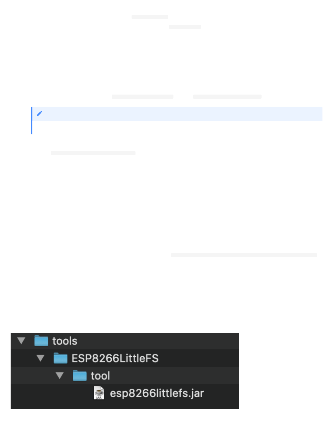
Step 4 - Install the filesystem upload tool for ESP8266
The ESP8266 has flash memory that can hold a filesystem. There is a plugin for Arduino that allows you to generate a populated filesystem and upload it to the
ESP8266 board. The plugin can be downloaded from here. You need to create a tools directory within the sketch directory then extract the content there.
•
•
•
•
•
you will need to change the version number in the command above if you downloaded a version newer than 1.8.7
Note
•
•
•
•
•
•
2.2.3 Installing the required software
- 11/145 -

The default location of the sketch directory is:
Linux - /home/< user name >/Arduino/tools/ESP8266LittleFS
MacOS - /Users/< user name >/Documents/Arduino/tools/ESP8266LittleFS
Windows - C:\Users\< user name >\Documents\Arduino\tools\ESP8266LittleFS
STEP 5 - SSL UTILITY TO WORK WITH CERTIFICATES
During the workshop you will be generating your own self-signed certificates, so need the OpenSSL tooling installed. Follow the instructions for your OS below:
Linux : openssl is installed as part of the OS for most distros, so should have nothing to do here. If it is not installed then most distros have an openssl
package which can be installed using the distro package installer tool.
MacOS : openssl is installed as part of the OS, so nothing to do here.
Windows : There are 2 options for installing OpenSSL on Windows. You can install a binary distribution to run on Windows or you can enable the Windows
Subsystem for Linux, which provides a Linux environment within Windows:
Windows Binary: The openssl official website only provides source. You can choose to build the binaries from source, but there are links to sites hosting
prebuilt binaries, such as this site for 32 and 64 bit Windows. You want to select one of the 1.1.x versions. You only need light version for this workshop, but
you can choose the full version if you want the additional developer resources. When installing, the default install options are OK. The standard install does
NOT add the openssl executable to the system PATH, so you will need to specify the full path of the binary when entering commands, unless you add it to
the PATH, e.g. c:\OpenSSL-Win64\bin\openssl.exe .
Windows Subsystem for Linux: This option installs a Linux distribution within Windows, so you get access to all the Linux utilities and can install
additional packages, such as openssl. To enable Linux Services for windows follow the instructions here. Select Debian as the Linux distribution, then when
it is installed launch Debian then run the following commands at the Linux command prompt:
2.2.4 Ensure you have a working IBM Cloud account
The workshop will use services hosted on the IBM Cloud, so you need to ensure you have a working account. If not you can sign up for free, without needing to
input any credit card details, by following this link. The workshop can be completed using the free, lite account.
you can find the sketch directory location from the preferences panel of the Arduino IDE
Note
•
•
•
•
•
•
•
this method will not provide the xxd binary, but you don't need it for this workshop. If you get an error saying
MSVCR120.dll
is missing, then you can download
the Visual Studio 2013 redistibutable package
here
Note
•
sudo apt-get update
;
sudo apt-get upgrade
sudo apt-get install openssl
2.2.4 Ensure you have a working IBM Cloud account
- 12/145 -

2.3 Your first ESP8266 application
2.3.1 Lab Objectives
This Lab will show you how to use the Arduino IDE with the ESP8266 plugin to create a new application for the ESP8266 board. You will learn how:
Ensure you have the correct settings in the IDE
How to compile source code into a binary
How to upload a binary onto the board
You should also take time to understand the flow of an Arduino application, and the purpose of the setup() and loop() functions.
Step 1 - Setting up the Arduino environment for the ESP8266
Let's start with a simple application to display information about the flash memory. Start by setting up your Arduino IDE to the correct settings for the board.
Using the Tools menu, ensure the following settings are set:
Board : NodeMCU 1.0 (ESP-12E Module)
Upload Speed : 115200
CPU Frequency : 160 MHz
Flash Size : 4M (FS:1M OTA~1019KB)
Debug Port : Disabled
Debug Level : None
IwIP Variant : v2 Lower Memory
vTables: Flash
Exceptions: Disabled
Erase Flash : Only Sketch
SSL Support : Basic SSL ciphers (lower ROM use)
Port : Connect the ESP8266 to your laptop using a MicroUSB cable and then select your port, depending on OS
Step 2 - Loading an example sketch
Then choose File -> Examples -> ESP8266 -> CheckFlashConfig from the menu to open a new window with the sample sketch preloaded (you can close the
previous window as it is not needed).
Step 3 - Compiling the sketch
You can now compile the sketch for the ESP8266 by selecting the Verify button on the command bar (tick icon) or using the sketch -> Verify/Compile menu
option. You will see there are keyboard short cuts for various commands, shown next to the menu option which you may want to learn and use.
Step 4 - Uploading the sketch
•
•
•
•
•
•
•
•
•
•
•
•
•
•
•
•
2.3 Your first ESP8266 application
- 13/145 -
Once the compile has finished you can upload the new application to your ESP8266 using the upload button on the command bar (arrow to right icon) or using
the Sketch -> Upload menu option.
If you try to save the sketch you will be prompted to enter a name/location for the sketch. This is because the example sketches are read-only, if you want to
modify them and save the modification you need to save it to a new location.
This example sketch prints out information about the flash memory on board the ESP8266. To see the output you need to open up the Serial Monitor.
Ensure the baud rate at the bottom of the monitor window matches the baud rate in the setup function of the sketch Serial.begin(115200); .
Step 5 - Understand the example sketch
The Arduino IDE and runtime take care of the work needed to setup the runtime for an application and provides 2 entry points. A setup() function, which is called
at the start of the application, or when the device comes out of a deep sleep. The other entry point is the loop() function which is repeatedly called so long as the
device is running.
There is no operating system running under the Arduino application, the code you enter in setup and loop is all that is running on the ESP8266 CPU.
This example sketch initialises the Serial connection in the setup() function then retrieves and prints information about the flash memory to the Serial console in
the loop() function. At the end of the loop() function there is a delay for 5 seconds (5000 milliseconds). After the delay the loop() function ends, but is
immediately called again.
you don't need to compile then upload. Just using upload will compile the application if necessary then upload it to the ESP8266
Note
2.3.1 Lab Objectives
- 14/145 -
2.4 Connecting the ESP8266 to a WiFi network
2.4.1 Lab Objectives
This Lab will show you how to connection your ESP8266 to a local WiFi network. This Lab will also introduce the Serial Monitor, which allows you to see output
from a running application. By the end of this lab you should:
Be able to add a WiFi connection to a sketch
Be able to add a Serial connection and generate output to the serial connection.
Understand the function calls needed to start up the WiFi and Serial connections then how to use the connections and where to find documentation about
the functions available.
2.4.2 Introduction
In the First App practical you verified you had a working development environment and uploaded your first application to the ESP8266. Now we will start
exploring some of the more advanced functionality of the ESP8266, starting with the on board WiFi interface.
The ESP8266 has a built in WiFi interface that supports 802.11 b/g/n 2.4 GHz networking. 5GHz frequencies are not supported. The ESP8266 can be setup to be
an access point or to join an existing Wireless LAN. We are going to join a LAN in the workshop.
Step 1 - Load an example sketch
In the Arduino IDE, load the WiFiScan example sketch, using File -> Examples -> ESP8266WiFi -> WiFiScan then upload the sketch to your ESP8266. This
sketch will scan for local WiFi networks and display the results.
Step 2 - Run the sketch and monitor output
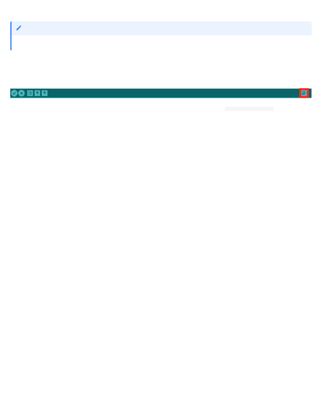
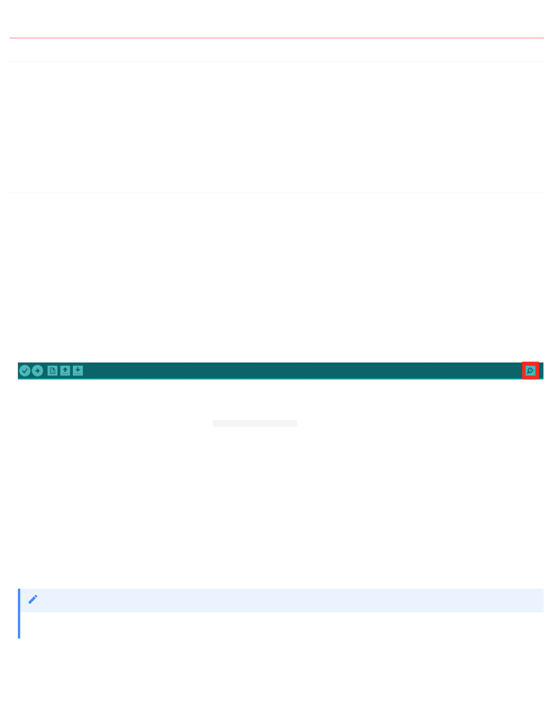
To display the results, the sketch is using the Serial interface on the ESP8266 to send output to. This output will be sent back into the USB port on your laptop/
workstation. To see the output you need to open up the Serial Monitor, which is the magnifying glass icon at the top right of the IDE. You must ensure that the
baud rate set in the serial monitor matches the speed of the Serial.begin(115200); statement in the setup function in the sketch.
Every 5 seconds you will see the board scan for available networks then output what it finds to the serial port.
Step 3 - Access the documentation for the enhanced ESP8266 library
You can get documentation about using ESP8266 in Arduino and the libraries that are installed with the ESP8266 plugin from here. If you finish this assignment
early modify the sketch to show the channel number each network is using and the encryption type in addition to the SSID and RSSI(signal strength).
Step 4 - How to connect to a WiFi network
The example sketch WiFiClient shows how to connect to a WiFi network, providing a SSID and password, which we will use in part 2 of the workshop. Load the
sketch (File -> Examples -> ESP8266WiFi -> WiFiClient) and examine the code, take note of how the WiFi network credentials are entered to join a network.
•
•
•
you don't need to run this example and apply for the sparkfun credentials, simply walk through the code and see how the connection to the WiFi is created.*
Note
2.4 Connecting the ESP8266 to a WiFi network
- 15/145 -

Step 5 - Understanding the pattern of using the ESP8266 Library
Now you have seen 2 different example sketches using both Serial and WiFi connections. You may begin to see a pattern on how to use the resources:
Optionally include the required header, such as
#include "ESP8266WiFi.h"
In the setup() function initialise the library, usually with a begin() call and/or setting parameters
In the loop() function access features of the library
•
•
•
If you finish early jump back to step 3 to add the additional functionality
Note
2.4.2 Introduction
- 16/145 -

2.5 Controlling the RGB LED from the ESP8266
2.5.1 Lab Objectives
In this Lab you will connect the NeoPixel LED and learn how to control it from the ESP8266. You will learn:
The electrical connections of the LED and how to connect to the ESP8266
The library used to control the neopixel
How to add new libraries to the Arduino IDE
How to use the neopixel Library and access documentation for additional features
2.5.2 Introduction
During the last practical we used the ESPWiFi library that was installed as part of the plugin but now we want to control a neopixel RGB LED that we will
connect to the ESP8266. One of the advantages of using Arduino is that there are many libraries available, so most common hardware will usually have an
Arduino library available, so you won't need to implement the low-level control protocol for a device.
You need to be careful to ensure that any library you choose supports the hardware you are running on. Initially the Arduino platform was created around AVR
microprocessors and many libraries were written to directly interact with AVR processors, so are incompatible when targeting a different processor. Looking at the
Arduino ESP8266 documentation there is a list of libraries known to work with ESP8266.
Step 1 - Adding a Library to the Arduino IDE
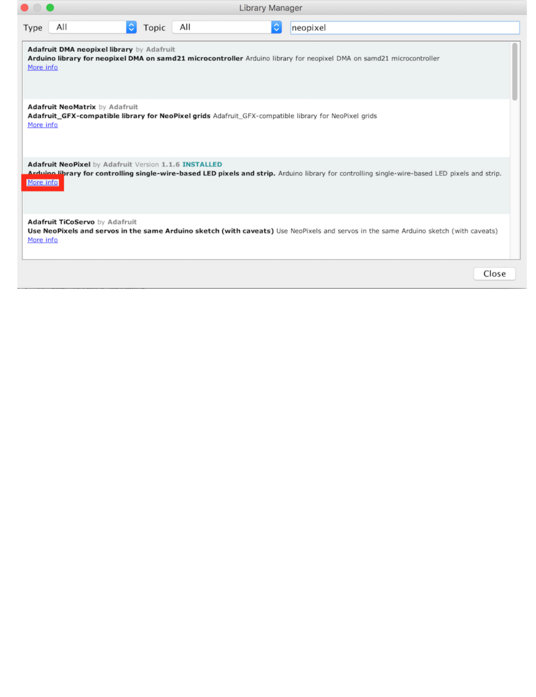
Looking at the list, there is a compatible NeoPixel library available for the neopixel. To install a library into the Arduino IDE you can use the Library Manager.
From the menu select Sketch -> Include Library -> Manage Libraries... to bring up the Library Manager. In the search box enter NeoPixel to find libraries
matching the search. You can see there are a number of libraries available, but you want to find the Adafruit NeoPixel by Adafruit, then select the entry and
click install to install the library. Once the library in installed click close to close the Library Manager.
Step 2 - Connecting the Neopixel to the ESP8266 board
Now you need to connect the NeoPixel to the ESP8266. Before you start making any connections please disconnect the device from your laptop/workstation so
there is no power getting to the device. You should never make any connection changes when the device is powered on.
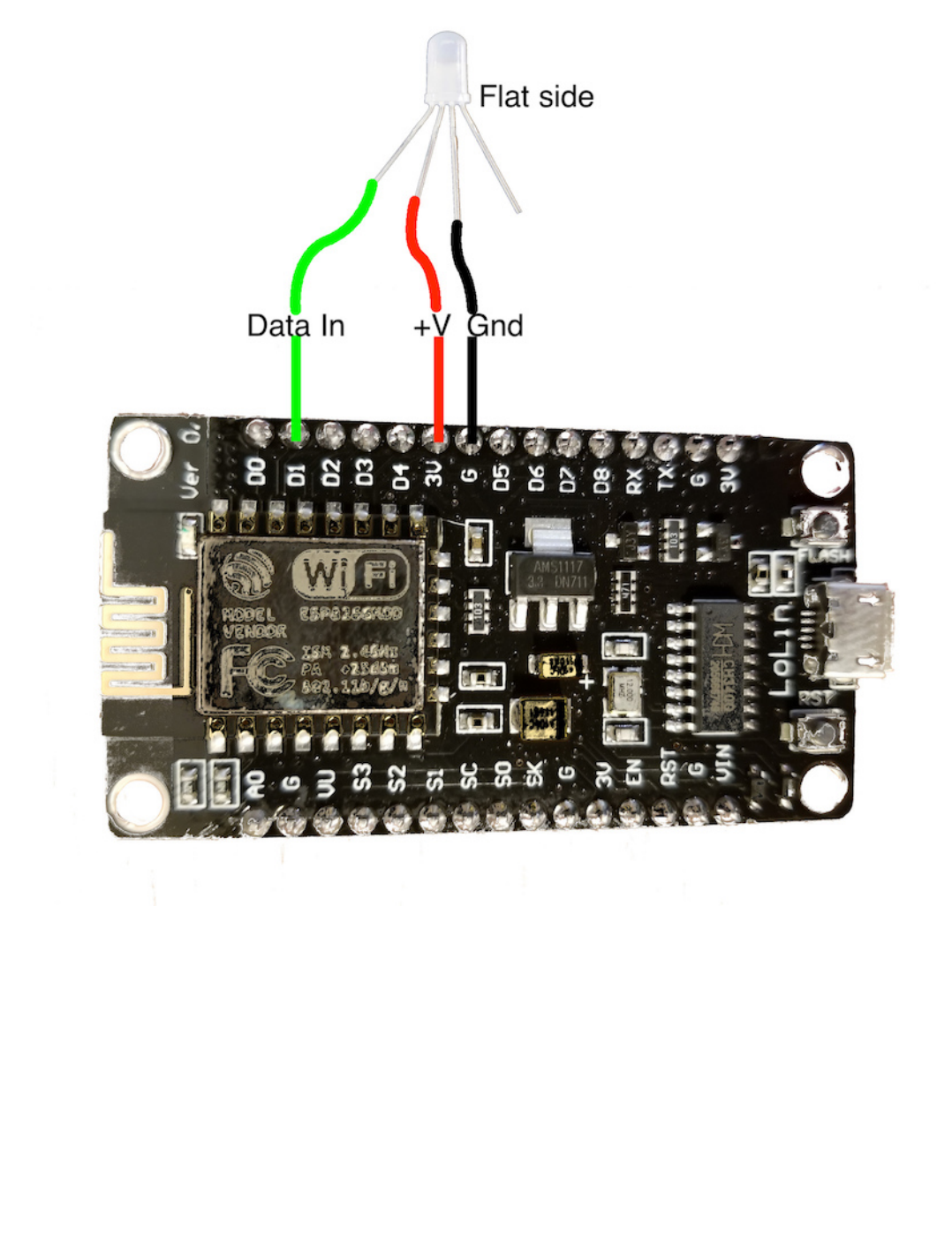
Before making the connections we need to identify the 4 connecting pins coming out of the LED. If you examine the rim of the pixel cover you will see that one
side is flattened (this should be the opposite side from the shortest pin) - this pin next to the flattened side is the Data Out pin. We will not be using this pin, as
we only have a single pixel. You can chain pixels together connecting the Data Out pin to the Data In pin of the next pixel in the chain.
The shortest pin on the Pixel is the Data In The longest pin on the Pixel is Ground The remaining pin is +'ve voltage, which should be 5v, but it works with 3.3v
that the ESP8266 board provides.
So, with the shortest pin on the left and the flat side on the right the pinout is (left to right):
Data In (shortest pin)
+'ve Voltage
Gnd (longest pin)
Data Out (no connection)
You need to connect the Data In, +'ve voltage and ground to the ESP8266 board as shown in the diagram. Take care to ensure that the connections are as shown,
as connecting the wrong pins can damage the ESP8266 board and/or the LED:
•
•
•
•
•
•
•
•
2.5 Controlling the RGB LED from the ESP8266
- 17/145 -
Step 3 - Load an example sketch
Once you have the connections made you can connect the board to your laptop. Load the example sketch strandtest File -> Examples -> AdaFruit Neopixel ->
strandtest. You need to make a couple of changes to the example sketch:
Change the LED_PIN number to 5. D1 on the NodeMCU board maps to GPIO5 on the ESP8266 processor - see the pinout
Set the number of pixels to 1 in the LED_COUNT definition
In the loop function comment out the 4 lines starting with theaterChase as these cause rapid flashing when only a single LED is connected, which is not
pleasant to look at
When you save the file you should be prompted to save it as a new file (you cannot override example files, so need to save them to another location to be able to
modify them).
Compile and upload the sketch to see the LED change colours.
1.
2.
3.
2.5.2 Introduction
- 18/145 -

The top of your code should look like this:
#include
<Adafruit_NeoPixel.h>
#ifdef __AVR__
#include
<avr/power.h>
// Required for 16 MHz Adafruit Trinket
#endif
// Which pin on the Arduino is connected to the NeoPixels?
// On a Trinket or Gemma we suggest changing this to 1:
#define LED_PIN 5
// How many NeoPixels are attached to the Arduino?
#define LED_COUNT 1
// Declare our NeoPixel strip object:
Adafruit_NeoPixel
strip
(
LED_COUNT
,
LED_PIN
,
NEO_GRB
+
NEO_KHZ800
);
// Argument 1 = Number of pixels in NeoPixel strip
// Argument 2 = Arduino pin number (most are valid)
// Argument 3 = Pixel type flags, add together as needed:
// NEO_KHZ800 800 KHz bitstream (most NeoPixel products w/WS2812 LEDs)
// NEO_KHZ400 400 KHz (classic 'v1' (not v2) FLORA pixels, WS2811 drivers)
// NEO_GRB Pixels are wired for GRB bitstream (most NeoPixel products)
// NEO_RGB Pixels are wired for RGB bitstream (v1 FLORA pixels, not v2)
// NEO_RGBW Pixels are wired for RGBW bitstream (NeoPixel RGBW products)
// setup() function -- runs once at startup --------------------------------
void
setup
()
{
// These lines are specifically to support the Adafruit Trinket 5V 16 MHz.
// Any other board, you can remove this part (but no harm leaving it):
#if defined(__AVR_ATtiny85__) && (F_CPU == 16000000)
clock_prescale_set
(
clock_div_1
);
#endif
// END of Trinket-specific code.
strip
.
begin
();
// INITIALIZE NeoPixel strip object (REQUIRED)
strip
.
show
();
// Turn OFF all pixels ASAP
strip
.
setBrightness
(
50
);
// Set BRIGHTNESS to about 1/5 (max = 255)
}
// loop() function -- runs repeatedly as long as board is on ---------------
void
loop
()
{
// Fill along the length of the strip in various colors...
colorWipe
(
strip
.
Color
(
255
,
0
,
0
),
50
);
// Red
colorWipe
(
strip
.
Color
(
0
,
255
,
0
),
50
);
// Green
colorWipe
(
strip
.
Color
(
0
,
0
,
255
),
50
);
// Blue
// Do a theater marquee effect in various colors...
//theaterChase(strip.Color(127, 127, 127), 50); // White, half brightness
//theaterChase(strip.Color(127, 0, 0), 50); // Red, half brightness
//theaterChase(strip.Color( 0, 0, 127), 50); // Blue, half brightness
rainbow
(
10
);
// Flowing rainbow cycle along the whole strip
//theaterChaseRainbow(50); // Rainbow-enhanced theaterChase variant
}
2.5.2 Introduction
- 19/145 -

Step 4 - Understanding how use the neopixel library
To add the NeoPixel to your own application you need to do the following:
Create an instance of a Neopixel
Adafruit_NeoPixel strip(LED_COUNT, LED_PIN, NEO_GRB + NEO_KHZ800);
The first parameter is the number of pixels in the chain
the second parameter is the GPIO number the pixel(s) are connected to
The third parameter allows you to identify what type of pixel is connected. There are a number of different types of pixel. Some include a white LED to
give a better white light. Some expect the green data to be sent first whilst others require the red data to be sent first. There are also different
communication speeds used.
Before using any commands to alter the pixels you need to initialise the pixel library using the begin() call. strip.begin(); This is usually done in the
setup() function.
Set the pixels to the desired colours
There are a number of calls in the neopixel library to be able to set the colour of a pixel. The first parameter always is the number of the pixel you want to
set in the chain (starting with 0 as the first pixel):
setPixelColor(uint16_t n, uint8_t r, uint8_t g, uint8_t b)
setPixelColor(uint16_t n, uint8_t r, uint8_t g, uint8_t b, uint8_t w)
setPixelColor(uint16_t n, uint32_t c)
There are 2 ways to specify a colour to the setPixelColor() call. You can pass in the red, green, blue and optionally white values (0 - 255) for each of the
LEDs within the pixel or use the Color() function to create a single 32bit integer value representing a colour. This can be useful for passing to and returning
from other function calls, as shown in the example sketch:
Color(uint8_t r, uint8_t g, uint8_t b)
Color(uint8_t r, uint8_t g, uint8_t b, uint8_t w)
Call the show() function to send the colour changes to the pixel(s) : strip.show(); . This is the function that actually updates the pixels based on the
previous setPixelColor function calls.
For any library installed with the Arduino Library Manager you can get to the documentation for the library using the More info link in the Library Manager:
1.
•
•
•
2.
3.
this doesn't change the pixel colours immediately
Note
•
•
•
•
•
•
•
•
2.5.2 Introduction
- 20/145 -
2.5.2 Introduction
- 21/145 -

2.6 Reading the DHT Sensor from the ESP8266
The DHT11 or DHT22 sensors add the ability to sense temperature and humidity. The DHT22 is a more accurate version of the DHT11.
2.6.1 Lab Objectives
In this lab you will learn how to connect the DHT temperature and humidity sensor to the ESP8266 board and how to access data from the sensor. You will learn:
The electrical connections needed to connect the DHT sensor to the ESP8266
The library used to access the features of the sensor
How to use the library functions to add a DHT sensor to an application
Step 1 - Installing the Library
To access the DHT sensors from the ESP8266 we need to add 2 libraries to the sketch, so back in the Arduino IDE access the library manager. Sketch -> Include
Library -> Manage Libraries....
Once in the Library Manager search for DHT. The top entry should be the Adafruit DHT sensor library which you should install.
Adafruit have introduced a unified model to many of their sensor libraries, including the DHT library, and to use them you need to install the Adafruit
Unified Sensor library, so search for it, it will appear at the bottom of the list, then install it.
When both of the libraries have been installed you can close the library manager.
Step 2 - Connect the DHT sensor to your ESP8266 board
Disconnect the ESP*266 board from your laptop/workstation before connecting the DHT sensor.
•
•
•
•
•
2.6 Reading the DHT Sensor from the ESP8266
- 22/145 -
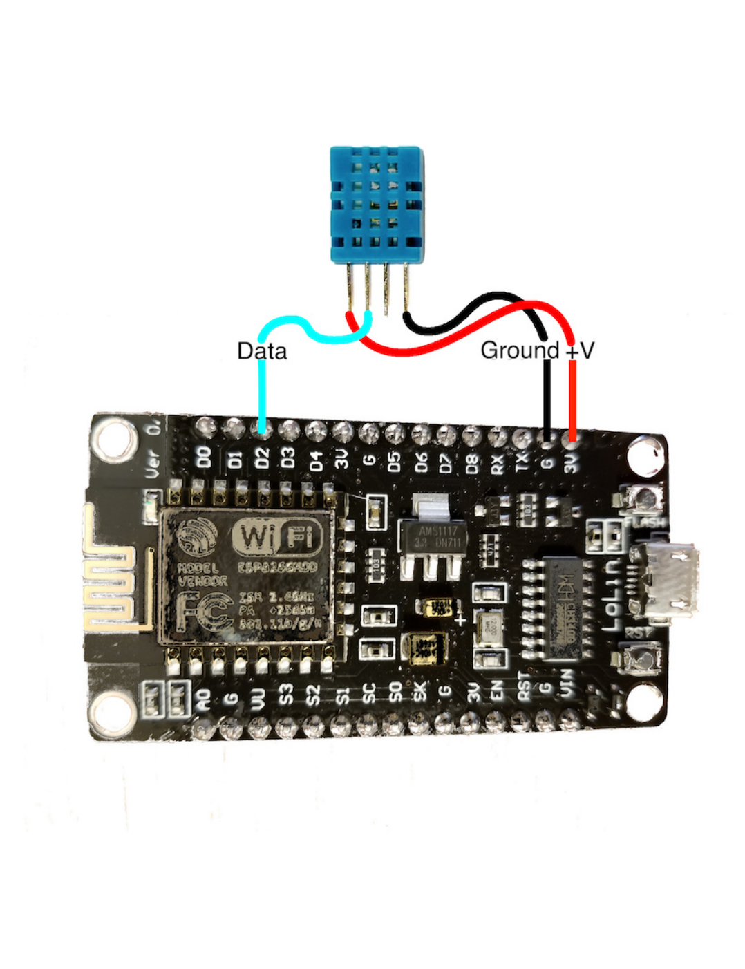
The DHT sensors have 4 connecting pins. When looking at the front of the sensor (mesh case) with the pins at the bottom, the connections are (left to right):
+'ve voltage
Data
Not used
Ground
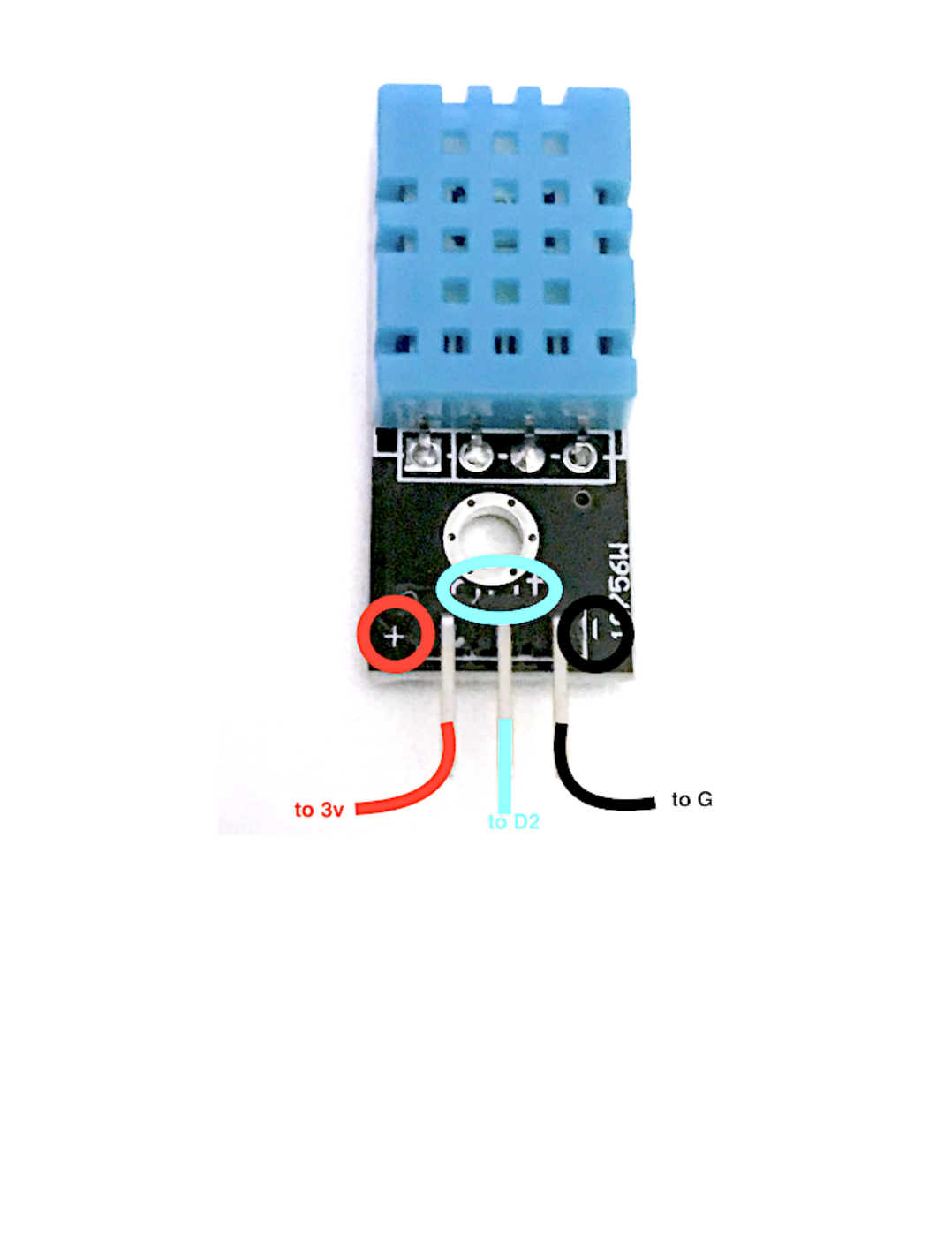
If you have a DHT mounted on a module then you need to check the pinout, usually indicated on the board, with + (to 3V pin), - (to G pin) and out or data (to D2
pin):
•
•
•
•
2.6.1 Lab Objectives
- 23/145 -
Step 3 - Load an example sketch showing how to use the DHT sensor
To see how to use the DHT sensor there is an example sketch. File -> Examples -> DHT Sensor Library -> DHTtester. You need to make a couple of changes
before you can run the sketch:
Update the DHTPIN to the correct GPIO pin on the ESP8266 corresponding to D2 on the NodeMCU board. The pinout diagram will tell you that you need GPIO
4.
Set the DHT type. If you are using DHT11 sensors (blue), uncomment the DHT11 line and comment out the DHT22 line.
When you save the sketch you will need to save it to your Arduino directory as you can't modify the example source. Once saved you can now compile and
upload the sketch. This sketch uses Serial output to print out the values read, so you will need to open the Serial monitor and set the baud rate to match the
Serial.begin() line in the sketch = 9600.
1.
2.
2.6.1 Lab Objectives
- 24/145 -

Step 4 - Understanding the DHT sensor library
To add the DHT sensor to your own application you need to do the following:
Create an instance of DHT :
DHT dht(DHTPIN, DHTTYPE);
The first parameter is the GPIO the data pin is connected to
the second parameter is the type of sensor
Before using and commands to read the sensor you need to initialise the sensor library using the begin() call. dht.begin(); This is usually done in the setup()
function.
Read the sensor required using one of the library functions:
dht.readTemperature()
dht.readTemperature(bool isFahrenheit)
dht.readHumidity()
1.
•
•
2.
3.
by default temp is in C, but you can request to get a Fahrenheit temperature.
Note
•
•
•
2.6.1 Lab Objectives
- 25/145 -

2.7 Deploying an application to the IBM Cloud
2.7.1 Lab Objectives
In this lab you will learn how to deploy a starter application to the IBM Cloud. You will learn:
How to access the cloud and set the desired location to work in
Access the catalog of services and select a Starter Application to deploy
Deploy a Starter Application to the IBM Cloud
Access the Starter Application source code and update the application
Become familiar with the DevOps tooling available in the IBM Cloud
2.7.2 Introduction
Before finishing part 1 you should deploy the Internet of Things Platform on the IBM Cloud as we will be using it in Part 2.
Before starting these steps it is assumed you have completed the steps in the prerequisite section and have an active IBM Cloud account.
2.7.3 Internet of Things Platform on the IBM Cloud
The IBM Watson IoT Platform solution provides a set of IBM Cloud services as a single IBM-managed Software as a Service (SaaS) offering that enables you to
collect and analyze IoT data.
In this workshop your ESP8266 device will be sending data to the IBM IoT Platform, so you need to deploy an instance of the IoT Platform service in your cloud
account.
Step 1 - Accessing the cloud and selecting an appropriate space
Login to your cloud account.
If you haven't previously used any of the Cloud Foundry locations you may need to create a space to be able to work in the chosen location. To do this from the
top menu select Manage -> Account -> Cloud Foundry Orgs then click on your mail address to configure your organisation. If there are no spaces showing, or you
have a paid account and want to work in a new region, then click to Add a space then select the region and provide a name for the space.
If you are working in a lite account you are restricted to a single Cloud Foundry space and are unable to create additional spaces in different regions unless you
upgrade your account.
Lite accounts have resource restrictions, so to be able to deploy the starter application you may need to delete any resources already deployed.
•
•
•
•
•
2.7 Deploying an application to the IBM Cloud
- 26/145 -
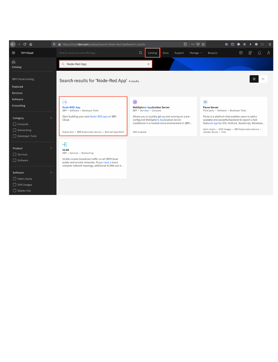
Step 2 - Deploy a Starter Application
open up the Catalog using the top menu
in the search bar enter Node-RED App and hit the ENTER key
select the Node-RED App tile
in the screen presented press the Get Started button
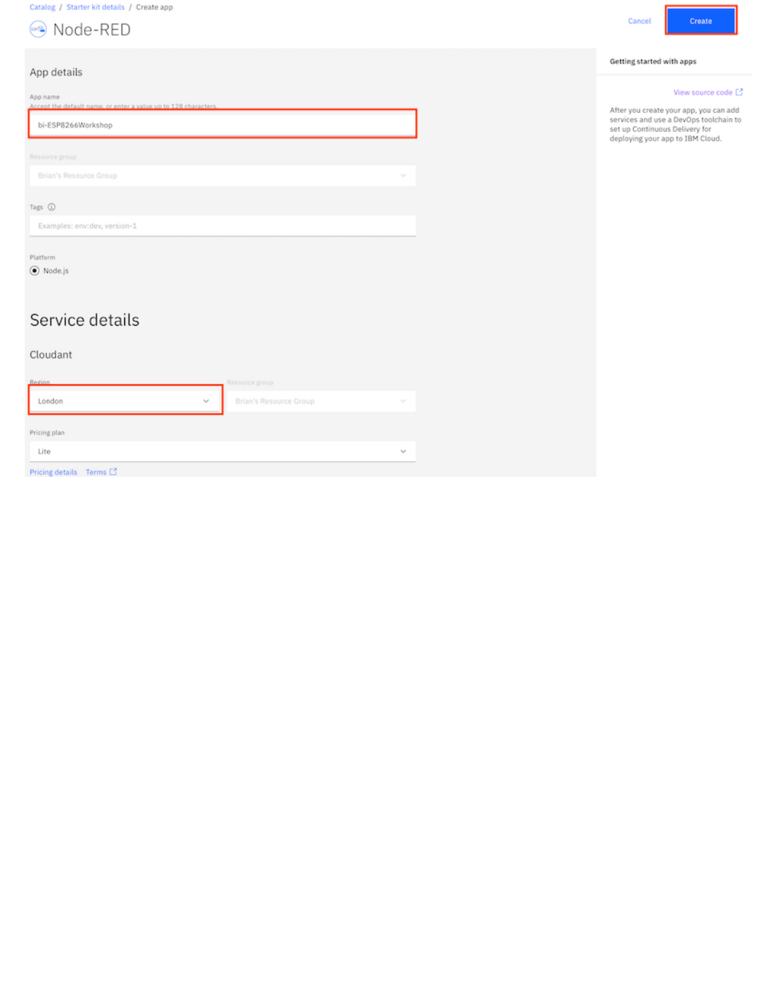
in the Create app screen optionally enter an App name (or you can simple accept the name provided) and select a region to deploy the Cloudant NoSQL
database to - ideally this should be the same region you have your Cloud Foundry space in.
press the Create button to create the App definition
•
•
•
•
•
•
2.7.3 Internet of Things Platform on the IBM Cloud
- 27/145 -
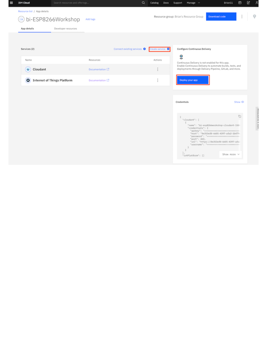
wait until the Cloudant service has been deployed
press the Create Service + button, then select the Internet of Things section and press the Next button
select the Internet of Things Platform then press the Next button
choose the closest region, ensure the Lite pricing plan is selected then press Create to add the Internet of Things Platform to your application
press Deploy you app
•
•
•
•
•
2.7.3 Internet of Things Platform on the IBM Cloud
- 28/145 -
ensure IBM Cloud Foundry is the deployment target (this is the only option for lite accounts)
press New to create an IBM Cloud API key, accept the defaults in the popup and press OK
select the Memory allocation per instance to 256 MB
ensure the host name is valid, if not modify it until any errors are cleared
select the region closest to you to application
press Next to get the options for deploying a toolchain
•
•
•
•
•
•
2.7.3 Internet of Things Platform on the IBM Cloud
- 29/145 -

select the region closest to you as the location you want the toolchain to be deployed to
press Create to deploy the toolchain
The Starter Application is now deploying by running the newly created toolchain.
Please leave this to deploy - now is a good time to go for a break.
•
•
2.7.3 Internet of Things Platform on the IBM Cloud
- 30/145 -
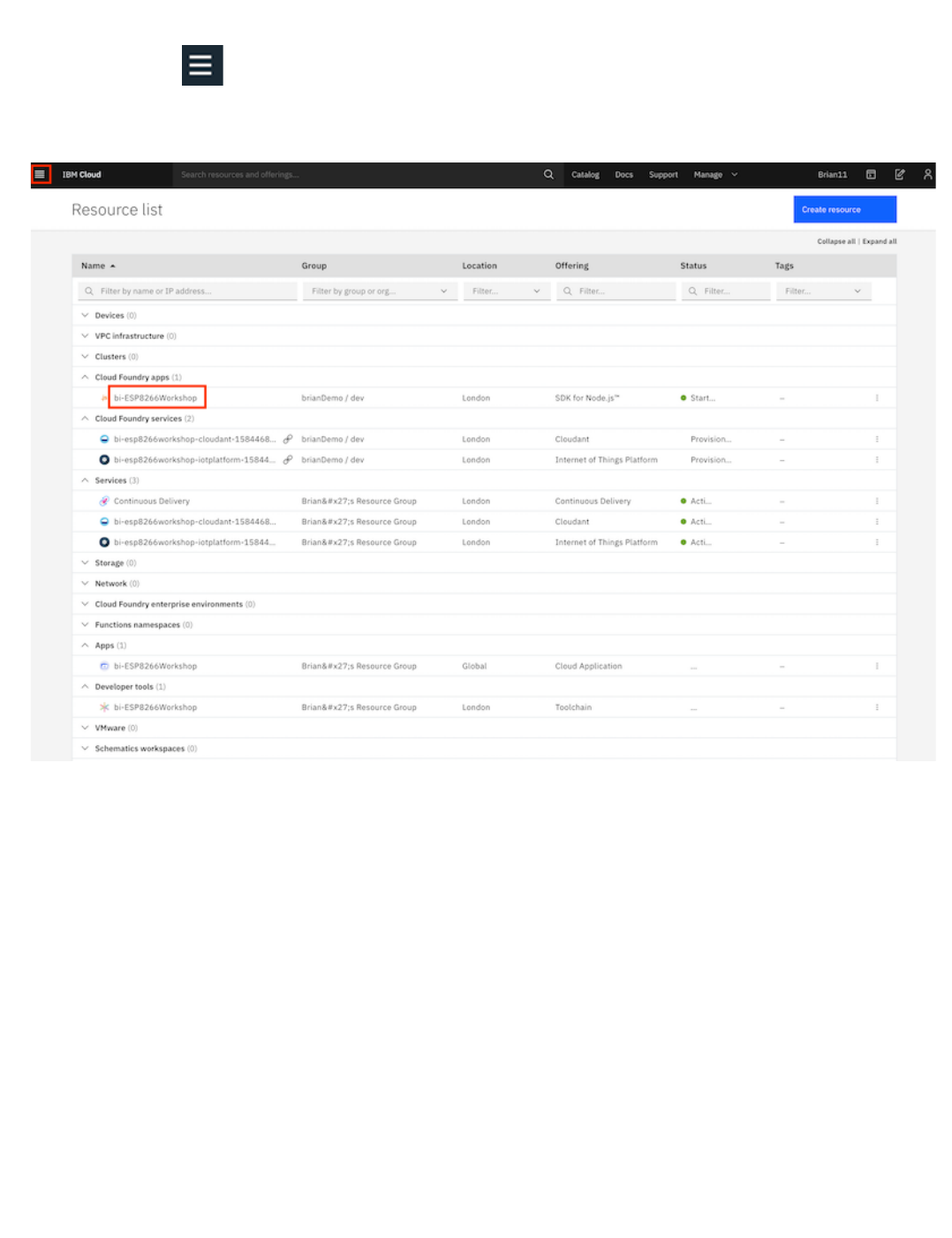
Step 3 - Check deployment status
open the main menu
(Top left of web console UI)
select Resource list
select your application from the Cloud Foundry apps section to launch the application overview page
•
•
•
2.7.3 Internet of Things Platform on the IBM Cloud
- 31/145 -
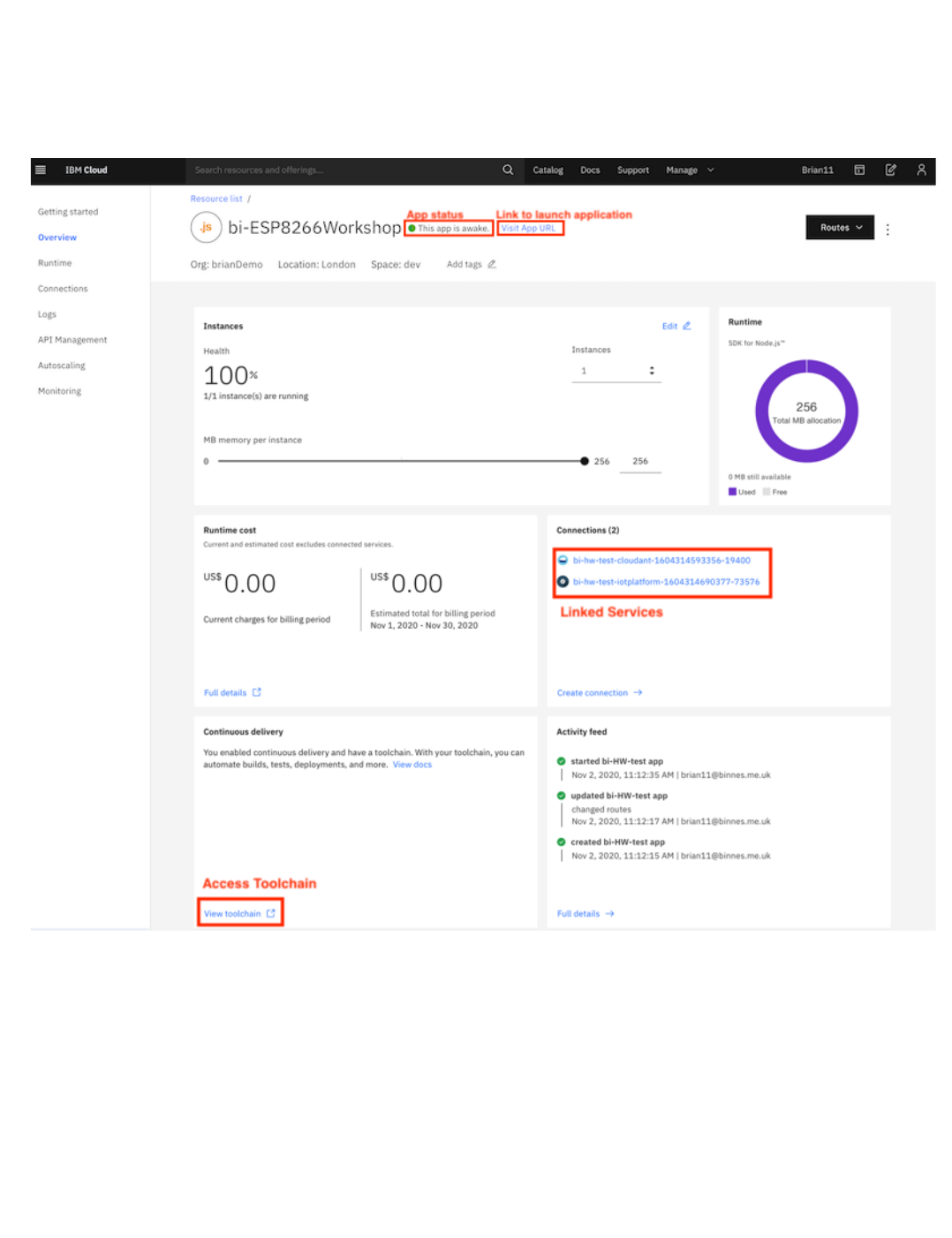
On the overview page you should see:
the app is awake, which shows the deployment was successful and the application is running
the link to open the application
the connections to the Cloudant database and IoT platform services
link to access toolchain
You now have the cloud application deployed, so you are now ready to move to the next section of the workshop to setup secured communications between the
ESP8266 device and the IBM Cloud IOT service
•
•
•
•
2.7.3 Internet of Things Platform on the IBM Cloud
- 32/145 -

3. Part 2
3.1 Part 2
3.1.1 Introduction to the IBM Internet of Things Platform
The IBM Internet of Things Platform is a set of services provided on the IBM Cloud to enable you to collect IoT data using MQTT events, we will cover MQTT
later in this section. In addition to data ingest, the IoT platfom provides a number of other services to allow you to capture the IoT data into short term storage in a
NoSQL database, monitor and analyze the IoT data and archive the data in Cloud Object Storage.
Before connecting the ESP8266 device to the IoT Platform you will configure the platform to allow the device to connect then later in this section you will
configure connection security to secure communications between the ESP8266 device and IBM Cloud.
3.1.2 Device Type / Device Creation
This Lab will show you how to register your ESP8266 with the IBM Internet of Things Platform.
Estimated duration: 15 min
practical Create device type and device
3.1.3 Creating the initial application
In this lab you will pull together all the information from part 1 into a single app.
Estimated duration: 15 min
practical Create ESP8266 application
3.1.4 Introduction to the MQTT protocol
In this lab you will learn how to add MQTT messaging to an application.
Estimated duration: 15 min
practical Sending data to the Watson IoT platform using MQTT
3.1.5 Introduction to IoT Security techniques
In this Lab you will modify MQTT to use a secure connection.
Estimated duration: 25 min
practical Securing the MQTT traffic using self-signed certificate
3.1.6 Adding client certificates
In this lab you will extend the application by enabling client side certificates.
Estimated duration: 10 min
practical Securing the MQTT traffic using a client certificate
•
•
•
•
•
•
•
•
•
•
3. Part 2
- 33/145 -
3.2 Registering a new device to the Watson IoT Platform
3.2.1 Lab Objectives
This Lab will show you how to register your ESP8266 with the IBM Watson Internet of Things Platform. In the lab you will learn:
How to navigate to the IoT Platform console
How to define a device type and register a device in the IoT Platform
3.2.2 Introduction
Before you can connect a device to the Watson IoT Platform you need to define how the device will connect to the platform and also register the device to
generate an access token for the device. This will be used to verify the device identity (we will come back to device authentication later in this part of the
workshop).
You need to decide how you want to group devices, by function, by hardware type, etc. Each device registered on the platform must be registered against a
device type. There are no restrictions about how devices are grouped and the device types, for this workshop we will create a device type representing the
ESP8266 devices.
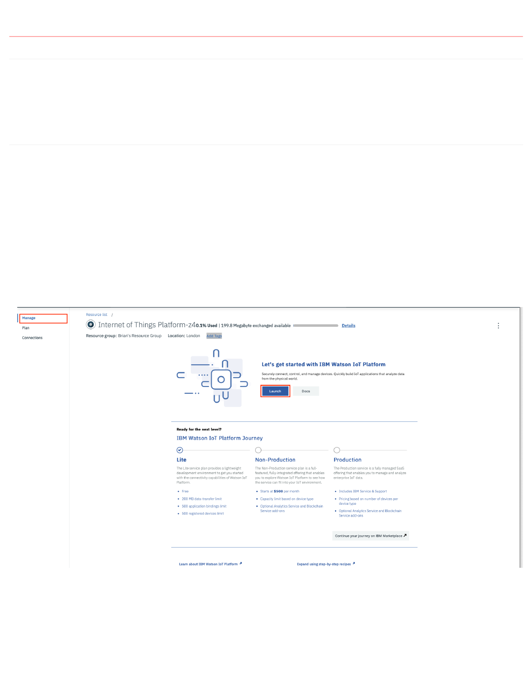
Step 1 - Launch the Watson IoT Platform console
In the IBM Cloud navigate to your dashboard using the top menu ≡ -> Resource list, then expand the Services section (ensure you select the Service section NOT
Cloud Foundry service section) and select your Internet of Things Platform service. This will take you to the IoT Platform service screen. Ensure the Manage
section is active then press the Launch button to open IoT platform console.
Step 2 - Add a new device type for ESP8266 devices
Navigate into the Devices section of the console and ensure you are in the Browse section. Press the + Add Device button the enter the following:
Device Type : Enter ESP8266
Device ID : Enter dev01
Select Next then Next to skip over the device information input screen
•
•
•
•
3.2 Registering a new device to the Watson IoT Platform
- 34/145 -

Step 3 - Specify a token for the device
You are now being prompted to provide a token. When developing I recommend choosing a token you can easily remember. I set all my devices to use the same
token when developing, but obviously this is not a good production practice.
Each time you connect the device the token will need to be presented to the server and once the device is registered there is no way to recover a token, you will
need to delete and reregister the device if the token is lost.
Enter a token for your device then press Next. You will see a summary of the device. Press Done to complete the device registration. You are now shown a
device Drilldown page - this is the last chance you get to see the token. Once you leave this page the token can not be recovered. Write down the Org, Device
Type, Device ID and Authentication Token. You might even consider taking a screen shot.
3.2.2 Introduction
- 35/145 -

3.3 Creating the sensing application for the ESP8266
3.3.1 Lab Objectives
In this lab you will pull together all the information from part 1 into a single app. You will learn:
How to create a new sketch and some recommendations for app structure
How to combine the WiFi, neopixel and DHT libraries into a single application
How to work with JSON data on the ESP8266
3.3.2 Introduction
In part 1 you looked at a number of example sketches to see how the WiFi, NeoPixel LED and DHT sensors work with Arduino. Now you will create an
application combining all the features then as we work through the remainder of this part you will connect the device to the IoT platform and add code to send
data to the platform and receive commands from the platform. Initially you will use unsecured MQTT connections, then at the end of this section you will add
SSL/TLS and certificate verification to secure the communication.
Step 1 - Create a new sketch
Create a new sketch in the Arduino IDE using File -> New or the icon in the tool bar. The save the sketch File -> Save and name the sketch, suggested name
esp8266Workshop.
You need to add 1 more library to the Arduino IDE to provide functions to handle the JSON data format. When we start sending and receiving data from the IoT
Platform the JSON data format will be used, so we can start using JSON now. In the Library Manager (Sketch -> Include Library -> Manage Libraries...) search
for ArduinoJson and install the latest version of the library.
Step 2 - Input the application code
I've provided the code for the application below. As you enter it (or cut and paste it) please take time to ensure you understand the application and what each of
the library function calls do.
Add the code below to the sketch above the setup() function:
•
•
•
You must have the latest version (6.x or higher) as the API changed from v5 to v6, so this code will not compile with v5 or earlier
Warning
#include
<ESP8266WiFi.h>
#include
<Adafruit_NeoPixel.h>
#include
<DHT.h>
#include
<ArduinoJson.h>
// --------------------------------------------------------------------------------------------
// UPDATE CONFIGURATION TO MATCH YOUR ENVIRONMENT
// --------------------------------------------------------------------------------------------
// Add GPIO pins used to connect devices
#define RGB_PIN 5
// GPIO pin the data line of RGB LED is connected to
#define DHT_PIN 4
// GPIO pin the data line of the DHT sensor is connected to
// Specify DHT11 (Blue) or DHT22 (White) sensor
#define DHTTYPE DHT11
#define NEOPIXEL_TYPE NEO_RGB + NEO_KHZ800
// Temperatures to set LED by (assume temp in C)
#define ALARM_COLD 0.0
#define ALARM_HOT 30.0
#define WARN_COLD 10.0
#define WARN_HOT 25.0
// Add WiFi connection information
char
ssid
[]
=
"XXXX"
;
// your network SSID (name)
char
pass
[]
=
"YYYY"
;
// your network password
3.3 Creating the sensing application for the ESP8266
- 36/145 -

The above code isolates all the configuration that may need to change. I prefer to put all the config up front in an app, so it is easy to update as needed. You will
need to update the WiFI SSID and password to the WiFi network you want to connect to. This should be available in the venue you are working in.
Add the following code to the setup() function:
This function initialises the Serial port, the WiFi connection, the LED and the DHT sensor.
The loop function should contain:
This code is called repeatedly after the setup() function returns. It reads the humidity and temperature for the DHT sensor, validates it received the readings then
sets the LED colour to the correct colour based on the temperature and the alert and warning temperatures defined in the constants at the top of the application.
Finally the temperature and humidity values are added to the JSON object, which is then converted to a string buffer and printed to the console.
// --------------------------------------------------------------------------------------------
// SHOULD NOT NEED TO CHANGE ANYTHING BELOW THIS LINE
// --------------------------------------------------------------------------------------------
Adafruit_NeoPixel
pixel
=
Adafruit_NeoPixel
(
1
,
RGB_PIN
,
NEOPIXEL_TYPE
);
DHT
dht
(
DHT_PIN
,
DHTTYPE
);
// variables to hold data
StaticJsonDocument
<
100
>
jsonDoc
;
JsonObject
payload
=
jsonDoc
.
to
<
JsonObject
>
();
JsonObject
status
=
payload
.
createNestedObject
(
"d"
);
static
char
msg
[
50
];
float
h
=
0.0
;
// humidity
float
t
=
0.0
;
// temperature
unsigned
char
r
=
0
;
// LED RED value
unsigned
char
g
=
0
;
// LED Green value
unsigned
char
b
=
0
;
// LED Blue value
void
setup
()
{
// Start serial console
Serial
.
begin
(
115200
);
Serial
.
setTimeout
(
2000
);
while
(
!
Serial
)
{
}
Serial
.
println
();
Serial
.
println
(
"ESP8266 Sensor Application"
);
// Start WiFi connection
WiFi
.
mode
(
WIFI_STA
);
WiFi
.
begin
(
ssid
,
pass
);
while
(
WiFi
.
status
()
!=
WL_CONNECTED
)
{
delay
(
500
);
Serial
.
print
(
"."
);
}
Serial
.
println
(
""
);
Serial
.
println
(
"WiFi Connected"
);
// Start connected devices
dht
.
begin
();
pixel
.
begin
();
}
void
loop
()
{
h
=
dht
.
readHumidity
();
t
=
dht
.
readTemperature
();
// uncomment this line for Celsius
// t = dht.readTemperature(true); // uncomment this line for Fahrenheit
// Check if any reads failed and exit early (to try again).
if
(
isnan
(
h
)
||
isnan
(
t
))
{
Serial
.
println
(
"Failed to read from DHT sensor!"
);
}
else
{
// Set RGB LED Colour based on temp
b
=
(
t
<
ALARM_COLD
)
?
255
:
((
t
<
WARN_COLD
)
?
150
:
0
);
r
=
(
t
>=
ALARM_HOT
)
?
255
:
((
t
>
WARN_HOT
)
?
150
:
0
);
g
=
(
t
>
ALARM_COLD
)
?
((
t
<=
WARN_HOT
)
?
255
:
((
t
<
ALARM_HOT
)
?
150
:
0
))
:
0
;
pixel
.
setPixelColor
(
0
,
r
,
g
,
b
);
pixel
.
show
();
// Print Message to console in JSON format
status
[
"temp"
]
=
t
;
status
[
"humidity"
]
=
h
;
serializeJson
(
jsonDoc
,
msg
,
50
);
Serial
.
println
(
msg
);
}
delay
(
10000
);
}
3.3.2 Introduction
- 37/145 -

Step 3 - Run the code and view output using the Serial Monitor
Save, compile and upload the sketch. Once uploaded open up the Serial Monitor and set the baud rate to 115200, to match the rate set in the
Serial.begin(115200) message. You should see the confirmation that the WiFi connection has been made and then you should see the sensor data formatted as a
JSON string, repeating every 10 seconds (10000 milliseconds).
The LED should also be set to a colour based on the temperature and the WARN and ALARM constants defined at the top of the sketch :
BLUE (below ALARM_COLD)
TURQUOISE (between ALARM_COLD and WARM_COLD)
GREEN (between WARN_COLD and WARN_HOT)
YELLOW (between WARN_HOT and ALARM_HOT)
RED (above ALARM_HOT)
Step 4 - Understanding how to work with JSON data
JSON format is widely used for APIs and data exchange between systems. The above sketch uses one of the optimised JSON libraries for small memory devices.
To use the library you need to:
Initialise the library and allocate some memory for the library to work with :
StaticJsonDocument<100> jsonDoc;
Create a new, empty JSON object : JsonObject payload = jsonDoc.to<JsonObject>();
Add required properties using one of the available functions:
The serializeJson() function converts the JSON object to a string and writes it into the provided buffer, so it can be used as a c-string.
See the library documentation for additional functionality.
•
•
•
•
•
1.
2.
3.
JsonObject
status
=
payload
.
createNestedObject
(
"d"
);
status
[
"temp"
]
=
t
;
status
[
"humidity"
]
=
h
;
3.3.2 Introduction
- 38/145 -

3.4 Connecting Device to the Watson IoT Platform using MQTT
3.4.1 Lab Objectives
In this lab you will learn how to add MQTT messaging to an application. You will learn:
How to connect to a MQTT broker using unsecured connection
How to use MQTT to connect to the Watson IoT platform
3.4.2 Introduction
In the previous lab you built the stand alone sensor application. Now we want to make it an Internet of Things application by adding in MQTT to send the data to
the IoT Platform.
We will start by using an unsecured MQTT connection, then in the next section we will secure the connection. However, the Watson IoT platform is configured to
block all unsecured connections by default, so you need to configure your Watson IoT service to allow unsecured connection.
Step 1 - Configure the Watson IoT platform to allow unsecured connections
Open up the IoT platform console for the instance connected to your Starter Kit application. From the dashboard (≡ -> Dashboard) select the application then in
the overview section select the IoT platform in the connections panel).
Launch the IoT platform console, then switch to the Settings section. Under Security select Connection Security then press the button Open Connection
Security Policy. Press the pencil icon next to Connection Security to edit the settings. Change the Default Security Level to TLS Optional, accept the Warning
message by pressing the Ok button, then Save the change. Your IoT platform instance will now accept unsecured MQTT connections. Leave the browser window
showing the IoT Platform console open, as you'll need to get some information when adding the MQTT code to the ESP8266 application.
Step 2 - Enhancing the application to send data to the IoT platform
In the Arduino IDE you need to add the MQTT code, but before adding the MQTT code you need to install the library. In the library manager (Sketch -> Include
Library -> Manage Libraries...) search for and install the PubSubClient. Then add the include to the top of the application, below the existing include files
#include <PubSubClient.h>
Now add some #define statements to contain that the MQTT code will use. Add these under the comment UPDATE CONFIGURATION TO MATCH YOUR
ENVIRONMENT:
You need to change the values to match your configuration:
XXXXXX should be the 6 character Organisation ID for your platform. If you look in the settings section of the IoT Platform console, under identity you will
see the value you need to use.
YYYY is the device type you used to for the ESP8266 device. This should be ESP8266, but you can verify by looking in the devices section. All registered
devices are listed here, and you can see the Device Type and Device ID.
ZZZZ is the device ID for your ESP8266, in the lab it was suggested to use dev01
PPPPP is the token you used when registering the device (hopefully you haven't forgot what you used, if so you need to delete the device and reregister it)
After the configuration block and under the pixel and dht variable declarations you need to add the the following:
•
•
// --------------------------------------------------------------------------------------------
// UPDATE CONFIGURATION TO MATCH YOUR ENVIRONMENT
// --------------------------------------------------------------------------------------------
// Watson IoT connection details
#define MQTT_HOST "XXXXXX.messaging.internetofthings.ibmcloud.com"
#define MQTT_PORT 1883
#define MQTT_DEVICEID "d:XXXXXX:YYYY:ZZZZ"
#define MQTT_USER "use-token-auth"
#define MQTT_TOKEN "PPPPP"
#define MQTT_TOPIC "iot-2/evt/status/fmt/json"
#define MQTT_TOPIC_DISPLAY "iot-2/cmd/display/fmt/json"
•
•
•
•
3.4 Connecting Device to the Watson IoT Platform using MQTT
- 39/145 -

Above the setup() function add the implementation of the callback function. This is called whenever a MQTT message is sent to the device. For now it just prints
a message to the serial console:
at the end of the setup() function add the following code to connect the MQTT client to the IoT Platform:
at the top of the loop() function add the following code to verify the mqtt connection is still valid and call the mqtt.loop() function to process any outstanding
messages:
Lastly add the code to send the data to the IoT Platform. We already have the data formatted as a JSON string, so we can now add the following code after it is
printed to the console in the loop() function:
Finally, replace the 10 second
delay(10000) to call the mqtt loop() function, so the program processes incoming messages:
Step 3 - Run the application
Compile and upload the code to your ESP8266 and you should see the WiFi Connected , followed by Attempting MQTT connection...MQTT Connected . Every
10 second interval you see the DHT sensor data printed on the console. The ESP8266 should also be publishing MQTT messages to the Watson IoT Platform. To
verify this, switch to your browser window showing the IoT Platform console, switch to the Devices section. Click on the esp8266 device to expand it then click
Recent Events. You should see the status event messages with the live data appearing every 10 seconds.
// MQTT objects
void
callback
(
char
*
topic
,
byte
*
payload
,
unsigned
int
length
);
WiFiClient
wifiClient
;
PubSubClient
mqtt
(
MQTT_HOST
,
MQTT_PORT
,
callback
,
wifiClient
);
void
callback
(
char
*
topic
,
byte
*
payload
,
unsigned
int
length
)
{
// handle message arrived
Serial
.
print
(
"Message arrived ["
);
Serial
.
print
(
topic
);
Serial
.
print
(
"] : "
);
payload
[
length
]
=
0
;
// ensure valid content is zero terminated so can treat as c-string
Serial
.
println
((
char
*
)
payload
);
}
// Connect to MQTT - IBM Watson IoT Platform
if
(
mqtt
.
connect
(
MQTT_DEVICEID
,
MQTT_USER
,
MQTT_TOKEN
))
{
Serial
.
println
(
"MQTT Connected"
);
mqtt
.
subscribe
(
MQTT_TOPIC_DISPLAY
);
}
else
{
Serial
.
println
(
"MQTT Failed to connect!"
);
ESP
.
reset
();
}
mqtt
.
loop
();
while
(
!
mqtt
.
connected
())
{
Serial
.
print
(
"Attempting MQTT connection..."
);
// Attempt to connect
if
(
mqtt
.
connect
(
MQTT_DEVICEID
,
MQTT_USER
,
MQTT_TOKEN
))
{
Serial
.
println
(
"MQTT Connected"
);
mqtt
.
subscribe
(
MQTT_TOPIC_DISPLAY
);
mqtt
.
loop
();
}
else
{
Serial
.
println
(
"MQTT Failed to connect!"
);
delay
(
5000
);
}
}
Serial
.
println
(
msg
);
if
(
!
mqtt
.
publish
(
MQTT_TOPIC
,
msg
))
{
Serial
.
println
(
"MQTT Publish failed"
);
}
// Pause - but keep polling MQTT for incoming messages
for
(
int
i
=
0
;
i
<
10
;
i
++
)
{
mqtt
.
loop
();
delay
(
1000
);
}
3.4.2 Introduction
- 40/145 -

Step 4 - How it works
When connecting to the Watson IoT platform there are some requirements on some parameters used when connecting. The platform documentation provides full
details:
The #define statements construct the required parameters:
host : < org id >.messaging.internetofthings.ibmcloud.com
device ID : d:< org id >:< device type >:< device id >
topic to publish data : iot-2/evt/< event id >/fmt/< format string >
topic to receive commands : iot-2/cmd/< command id >/fmt/< format string >
When you initialise the PubSubClient you need to pass in the hostname, the port (1883 for unsecured connections), a callback function and a network
connection. The callback function is called whenever incoming messages are received.
Call connect() to connect with the platform, passing in the device ID, a user, which is always the value use-token-auth and the token you chose when
registering the device.
The subscribe() function registers the connection to receive messages published on the given topic.
The loop() method must be regularly called to keep the connection alive and get incoming messages.
The publish() function sends data on the provided topic
You can verify the connection status with the connected() function.
Solution code
The complete ESP8266 application is shown below (you will need to change the configuration section to match your environment):
1.
2.
3.
4.
5.
6.
7.
8.
9.
10.
On some MQTT Client libraries this function only queues the message for sending, it is actually sent in the
loop()
function
Note
11.
#include
<ESP8266WiFi.h>
#include
<Adafruit_NeoPixel.h>
#include
<DHT.h>
#include
<ArduinoJson.h>
#include
<PubSubClient.h>
// --------------------------------------------------------------------------------------------
// UPDATE CONFIGURATION TO MATCH YOUR ENVIRONMENT
// --------------------------------------------------------------------------------------------
// Watson IoT connection details
#define MQTT_HOST "z53u40.messaging.internetofthings.ibmcloud.com"
#define MQTT_PORT 1883
#define MQTT_DEVICEID "d:z53u40:ESP8266:dev01"
#define MQTT_USER "use-token-auth"
#define MQTT_TOKEN "password"
#define MQTT_TOPIC "iot-2/evt/status/fmt/json"
#define MQTT_TOPIC_DISPLAY "iot-2/cmd/display/fmt/json"
// Add GPIO pins used to connect devices
#define RGB_PIN 5
// GPIO pin the data line of RGB LED is connected to
#define DHT_PIN 4
// GPIO pin the data line of the DHT sensor is connected to
// Specify DHT11 (Blue) or DHT22 (White) sensor
#define DHTTYPE DHT11
#define NEOPIXEL_TYPE NEO_RGB + NEO_KHZ800
// Temperatures to set LED by (assume temp in C)
#define ALARM_COLD 0.0
#define ALARM_HOT 30.0
#define WARN_COLD 10.0
#define WARN_HOT 25.0
// Add WiFi connection information
char
ssid
[]
=
"SSID"
;
// your network SSID (name)
char
pass
[]
=
"WiFi_password"
;
// your network password
// --------------------------------------------------------------------------------------------
// SHOULD NOT NEED TO CHANGE ANYTHING BELOW THIS LINE
// --------------------------------------------------------------------------------------------
3.4.2 Introduction
- 41/145 -

Adafruit_NeoPixel pixel = Adafruit_NeoPixel(1, RGB_PIN, NEOPIXEL_TYPE);
DHT dht(DHT_PIN, DHTTYPE);
// MQTT objects
void callback(char* topic, byte* payload, unsigned int length);
WiFiClient wifiClient;
PubSubClient mqtt(MQTT_HOST, MQTT_PORT, callback, wifiClient);
// variables to hold data
StaticJsonDocument<100> jsonDoc;
JsonObject payload = jsonDoc.to<JsonObject>();
JsonObject status = payload.createNestedObject("d");
static char msg[50];
float h = 0.0;
float t = 0.0;
unsigned char r = 0;
unsigned char g = 0;
unsigned char b = 0;
void callback(char* topic, byte* payload, unsigned int length) {
// handle message arrived
Serial.print("Message arrived [");
Serial.print(topic);
Serial.print("] : ");
payload[length] = 0; // ensure valid content is zero terminated so can treat as c-string
Serial.println((char *)payload);
}
void setup() {
// Start serial console
Serial.begin(115200);
Serial.setTimeout(2000);
while (!Serial) { }
Serial.println();
Serial.println("ESP8266 Sensor Application");
// Start WiFi connection
WiFi.mode(WIFI_STA);
WiFi.begin(ssid, pass);
while (WiFi.status() != WL_CONNECTED) {
delay(500);
Serial.print(".");
}
Serial.println("");
Serial.println("WiFi Connected");
// Start connected devices
dht.begin();
pixel.begin();
// Connect to MQTT - IBM Watson IoT Platform
if (mqtt.connect(MQTT_DEVICEID, MQTT_USER, MQTT_TOKEN)) {
Serial.println("MQTT Connected");
mqtt.subscribe(MQTT_TOPIC_DISPLAY);
} else {
Serial.println("MQTT Failed to connect!");
ESP.reset();
}
}
void loop() {
mqtt.loop();
while (!mqtt.connected()) {
Serial.print("Attempting MQTT connection...");
// Attempt to connect
if (mqtt.connect(MQTT_DEVICEID, MQTT_USER, MQTT_TOKEN)) {
Serial.println("MQTT Connected");
mqtt.subscribe(MQTT_TOPIC_DISPLAY);
mqtt.loop();
} else {
Serial.println("MQTT Failed to connect!");
delay(5000);
}
}
h = dht.readHumidity();
t = dht.readTemperature(); // uncomment this line for centigrade
// t = dht.readTemperature(true); // uncomment this line for Fahrenheit
// Check if any reads failed and exit early (to try again).
if (isnan(h) || isnan(t)) {
Serial.println("Failed to read from DHT sensor!");
} else {
// Set RGB LED Colour based on temp
b = (t < ALARM_COLD) ? 255 : ((t < WARN_COLD) ? 150 : 0);
r = (t >= ALARM_HOT) ? 255 : ((t > WARN_HOT) ? 150 : 0);
g = (t > ALARM_COLD) ? ((t <= WARN_HOT) ? 255 : ((t < ALARM_HOT) ? 150 : 0)) : 0;
pixel.setPixelColor(0, r, g, b);
pixel.show();
3.4.2 Introduction
- 42/145 -

// Send data to Watson IoT Platform
status
[
"temp"
]
=
t
;
status
[
"humidity"
]
=
h
;
serializeJson
(
jsonDoc
,
msg
,
50
);
Serial
.
println
(
msg
);
if
(
!
mqtt
.
publish
(
MQTT_TOPIC
,
msg
))
{
Serial
.
println
(
"MQTT Publish failed"
);
}
}
// Pause - but keep polling MQTT for incoming messages
for
(
int
i
=
0
;
i
<
10
;
i
++
)
{
mqtt
.
loop
();
delay
(
1000
);
}
}
3.4.2 Introduction
- 43/145 -

3.5 Adding secure communication between the device and IoT Platform using SSL/TLS
3.5.1 Lab Objectives
In this Lab you will modify MQTT to use a secure connection. You will learn:
How to add SSL/TLS capability to the network connection that MQTT uses
How to generate certificates to enable secure connections using OpenSSL
How to add the certificates to the IBM Watson IoT Platform
How to add the certificate to the ESP8266 using part of the flash memory as a file system
Basic operations of the ESP8266 file system
3.5.2 Introduction
Having unsecured traffic for an IoT solution is not a good idea, so in this lab you will convert the unsecured MQTT connection into a SSL/TLS connection.
When using SSL/TLS you can verify the certificate(s) presented by the server if you have the certificate of the Root Certificate Authority used to sign the server
certificate. Your Laptop will have common root CA certificates installed as part of the OS or browser so web traffic can be secured and the padlock on your
browser can be shown. However, you need to add any certificate to IoT devices if you want to verify server certificates.
The Watson IoT platform does allow you to replace the certificates used for MQTT traffic, so in this exercise you will generate your own self-signed certificates,
add them to the Watson IoT platform and the ESP8266 code, to enable a SSL/TLS connection with the server certificate verified against the root CA certificate
installed on the ESP8266.
The platform documentation provides information about what information must be contained in certificates to work with the platform.
In the prerequisite section you installed the OpenSSL tool, which allows you to work with certificates. I have provided 2 configuration files and 2 script files in
the certificates folder of this git repo. You need to download them and have them in the directory you will use to generate the certificates. If you have cloned or
downloaded the repo, then I suggest you work in the certificates directory.
The commands are provided to create text (pem) and binary (der) formats of the keys and certificates, as some device libraries require one or the other format. In
this workshop we will only use the text versions of the certificates and keys.
Step 1 - Generating the Certificates
To simplify the creation of the certificates use the provided script files. You need to modify the top section of the file (.bat file if you are working in a Windows
command window, .sh file if you are working on MacOS or in a Linux terminal window):
OPENSSL_BIN - needs to contain the openssl command. The provided value should work for default installs.
COUNTRY_CODE - is the country code where you are (for information purposes in cert - can leave at GB or you can find a list of valid ISO alpha-2
country codes here)
COUNTY_STATE - is the county, state or district where you are (for information purposes in cert - can leave at DOR, which is for Dorset, and English
county)
TOWN - is the city, town or village where you are (for information purposes in cert - can leave at Bournemouth)
IOT_ORG - MUST be the 6 character org id of your instance of the Watson IoT platform
DEVICE_TYPE - is the device type for your device, defined in the IoT platform. ESP8266 is the default value you were recommended to use in the
workshop instructions
DEVICE_ID - us the device id for your device, defined in the IoT platform. dev01 is the default value you were recommended to use in the workshop
instructions.
Do not make any modifications below the comment in the script file.
•
•
•
•
•
•
•
•
•
•
•
•
3.5 Adding secure communication between the device and IoT Platform using SSL/TLS
- 44/145 -

Once you have saved your changes you can run the script to generate all the certificates:
Linux, MacOS:
chmod +x makeCertificates.sh
. ./makeCertificates.sh
Windows:
makeCertificates.bat
Step 1a - INFORMATION ONLY
The script starts by generating a root CA key and certificate. This will then be used to sign a server certificate.
In a command windows enter the following commands, you need to replace some values, so do not just copy and paste the commands as shown, or your
certificates will not work!
The commands run by the script are:
replacing:
C=GB : GB is an ISO alpha-2 country code
ST=DOR : DOR is an English county, replace with appropriate state/county/region
L=Bournemouth : Bournemouth is an English town, replace with appropriate location
O=z53u40 : z53u40 is the Organisation ID for my IoT Platform
OU=z53u40 Corporate : z53u40 is the Organisation ID for my IoT Platform
CN=z53u40 Root CA : z53u40 is the Organisation ID for my IoT Platform
pass:password123 : password123 is the password that will protect the key - if you change this value do not forget what you entered, as you need it when
using the key later.
This generates the key and protects it with a password. A public certificate is then generated in pem format, which is then converted to der format. Finally the
xxd command creates a header file which allows the certificate to be embedded in code - this can be useful for devices that don't have a file system.
Step 2 - Uploading the root CA Certificate to the IoT Platform
You need to load the root CA certificate into the IoT platform using the console. In the settings section goto to CA Certificates in the Security section. Select to
Add certificate then select the rootCA_certificate.pem file you just generated to upload to the platform, then press Save.
Step 3 - INFORMATION ONLY - Generating a Server key and certificate
After generation the Root Certificate Authority key and certificate, the script generates the key and certificate for the MQTT server. It does this by generating a
key, then creating a certificate request file. The x509 takes the certificate request and the CA root certificate and key then generates the MQTT server certificate,
which is signed by the CA root certificate.
The MQTT server certificate must includes the DNS name of the server. This is used as part of the verification process at connection time, to ensure that the
client is talking to the intended server. The script generates the srvext_custom.cfg file with the correct DNS address for your instance of the Watson IoT platform.
To generate a certificate for the IoT platform the script runs the following commands:
•
•
openssl genrsa -aes256 -passout pass:password123 -out rootCA_key.pem
2048
openssl req -new -sha256 -x509 -days
3560
-subj
"/C=GB/ST=DOR/L=Bournemouth/O=z53u40/OU=z53u40 Corporate/CN=z53u40 Root CA"
-extensions v3_ca -set_serial
1
-passin
pass:password123 -key rootCA_key.pem -out rootCA_certificate.pem -config ext.cfg
openssl x509 -outform der -in rootCA_certificate.pem -out rootCA_certificate.der
xxd -i rootCA_certificate.der rootCA_certificate.der.h
•
•
•
•
•
•
•
openssl genrsa -aes256 -passout pass:password123 -out mqttServer_key.pem
2048
openssl req -new -sha256 -subj
"/C=GB/ST=DOR/L=Bournemouth/O=z53u40/OU=z53u40/CN=z53u40.messaging.internetofthings.ibmcloud.com"
-passin pass:password123 -key
mqttServer_key.pem -out mqttServer_crt.csr
openssl x509 -days
3560
-in mqttServer_crt.csr -out mqttServer_crt.pem -req -sha256 -CA rootCA_certificate.pem -passin pass:password123 -CAkey rootCA_key.pem -
extensions v3_req -extfile srvext.cfg -set_serial
11
3.5.2 Introduction
- 45/145 -

again substituting values for C=, ST=, L=, O=, OU= and CN=, but this time it is important that the CN value is the URL of your instance of the IoT messaging
URL, which is the Organisation ID followed by .messaging.internetofthings.ibmcloud.com, which should also match the subjectAltName field in the
srvext.cfg file.
The commands above generate a new key for the server, creates a certificate request for the server, issues the certificate and signs it with the root CA key, saving
it as a pem file. The certificate is converted from pem to der format and lastly the xxd command creates a header file to embed the certificate in code.
Step 4 - Add the server certificate to the IoT Platform
Now you have the server certificate you can upload to the IoT platform in the settings section of the console in the Messaging Server Certificates section under
Security. Select to Add Certificate then upload the certificate (mqttServer_crt.pem) and private key (mqttServer_key.pem). You need to also provide the
password you provided when creating the key (password123). Once the certificate is uploaded you enable it by setting the Currently Active Certificate to your
key.
Your can test the server certificate by using openssl:
replace
<CA certificate pem file> with the name of the CA root certificate and <org ID> with the 6 character org ID for your instance of the IOT Platform.
Step 5 - Adding the root CA certificate to the ESP8266
To allow the ESP8266 to validate the server certificate you need to add the root CA certificate to the ESP8266. The rootCA_certificate.pem needs to be added to
a directory called data in the sketch directory. You can find out where the sketch directory is by using the sketch -> Show sketch folder in the Arduino menu.
Inside the sketch directory create a new directory called data then copy the rootCA_certificate.pem file into the data directory. You added the data upload tool to
the Arduino IDE as part of the prerequisite setup instructions, so you can now run the tool. Before running the data upload tool ensure the Serial Monitor window
is closed, as it will block communication between the device and upload tool. From the top menu select Tools -> ESP8266 LittleFS Data Upload
Step 6 - Adding the root CA certificate to your OS or browser
Finally you need to add the root CA certificate to your OS or browser, as the IoT Platform console uses a secure connection to get data required to populate and
update the console in your browser. If you don't add the root CA Certificate then the console will not show any data.
If using Firefox you need to import the rootCA_certificate.pem file, by accessing the security section of the preferences. On some platform there is an Advanced
option before you are able to view certificates, then there is an option to import certificates then trust to identify web sites.
If using Chrome it depends on the platform. On some platforms Chrome uses the system certificates, but on others it manages its own certificates and then like
Firefox you need to go into the security settings to import the certificate authority certificate and trust it to identify web sites.
openssl x509 -outform der -in mqttServer_crt.pem -out mqttServer_crt.der
xxd -i mqttServer_crt.der mqttServer_crt.der.h
openssl s_client -CAfile <CA certificate pem file> -showcerts -state -servername <org ID>.messaging.internetofthings.ibmcloud.com -connect <org
ID>.messaging.internetofthings.ibmcloud.com:8883
3.5.2 Introduction
- 46/145 -

To add the root CA certificate to OS:
Linux: Many browsers on Linux do not use the OS certificates but manage their own certificate store, so check before adding the certificate to the OS
store. If you do need to add the rootCA certificate to the OS ca certificate store, then unfortunately there is not a standard way on Linux to achieve this.
Each distro has a slightly different approach, but many want the certificate to be a .crt file, so use the following command to convert the .pem to .crt:
openssl x509 -outform der -in rootCA_certificate.pem -out rootCA_certificate.crt
Debian: With admin privileges copy the rootCA_certificate.crt file to /usr/share/ca-certificates then run dpkg-reconfigure ca-certificates
Fedora: Copy the rootCA_certificate.pem file to /etc/pki/ca-trust/source/anchors/ (using sudo mv or other root access) then run command update-ca-
trust extract with admin privileges.
Ubuntu: Copy the rootCA_certificate.crt to /usr/local/share/ca-certificates using admin privileges then run update-ca-certificates .
MacOS: Double click the certificate in Finder to open it in the Keychain Access app. It will automatically show as not trusted. Double click it to open up
the certificate details window and then expand the Trust section. Change the SSL value to Always Trust. Close the certificate window (you will be
prompted for your account password to verify the change).
Windows: Launch the Microsoft Management Console (enter mmc in the start menu), then select File ->Add/Remove Snap-in.... Highlight Certificates and
press Add. Select to manage certificates for Computer account, Local computer then press Finish then OK. Back in the mmc, select the Certificates
item in the left column then right-click the Trusted Root Certificate Authorities item. From the popup menu select All Tasks -> Import... to launch the
Certificate Import Wizard. Select the rootCA_certificate pem or der file (may need to alter filter to show all files) and place it in the Trusted Root
Certificate Authorities store.
Step 7 - Updating the ESP8266 code to use the certificate to establish a secure connection
When a server connects using SSL/TLS it presents its own certificate for verification. The client uses its local CA certificate store to validate the certificate
presented by the server is authentic, by validating that a known CA signed the certificate.
Part of the certificate verification process checks that the certificate is in data (not before the start time of the certificate and not after certificate expiry time), so
the ESP8266 needs to know the correct date/time. The Network Time Protocol can be used to get the correct time from Internet servers.
You have already uploaded the CA certificate to the ESP8266, so now the code needs to be updated to load the certificate from the flash file system and switch
to using a SSL/TLS connection.
Make the following code changes:
Add an include at the top of the file to access the file system : #include <LittleFS.h>
Add an include after the ESP8266WiFi.h include to add time : #include <time.h>
Change the MQTT_PORT to use the secure port 8883 : #define MQTT_PORT 8883
Add a new #define to name the CA certificate : #define CA_CERT_FILE "/rootCA_certificate.pem"
Change the wifiClient to use the secure version : BearSSL::WiFiClientSecure wifiClient;
Add a new variable definition below the mqtt variable definition : BearSSL::X509List *rootCert;
Add #define to set timezone offset : #define TZ_OFFSET -5 //Hours timezone offset to GMT (without daylight saving time)
Add #define to set day light saving offset : #define TZ_DST 60 //Minutes timezone offset for Daylight saving
Modify the MQTT connection code in the setup() function to establish a secure connection:
•
•
•
•
•
•
If you are adding a certificate to a browser certificate manager, please ensure you are adding a Certificate Authority certificate. This should allow you to import a .pem or
.der file. If it is asking for a .p12 file then you are trying to import a certificate and key, so are in the wrong section of the certificate manager. You want to be adding a
Certificate Authority
certificate or certificate chain
Note
•
•
•
•
•
•
•
•
•
char
*
ca_cert
=
nullptr
;
// Get certs from file system and load into WiFiSecure client
LittleFS
.
begin
();
File
ca
=
LittleFS
.
open
(
CA_CERT_FILE
,
"r"
);
if
(
!
ca
)
{
Serial
.
println
(
"Couldn't load CA cert"
);
}
else
{
size_t
certSize
=
ca
.
size
();
3.5.2 Introduction
- 47/145 -

Save, compile and upload the code and now you should have a secure connection. If you look at the IoT Platform console, in the devices section you should now
see the connection state, in the Identity section when selecting the device, is connected with SecureToken. Previous the status would have shown Insecure.
You should now go into the IoT Platform settings section and update the connection security policy from TLS Optional to TLS with Token Authentication then
Save the change.
Step 8 - How the LittleFS file system works
The ESP8266 allows some of the on board or connected flash memory to be used as a file system. The Arduino IDE plugin allows you to customise the size of the
filesystem (Tools -> Flash Size allows you to specify 1MB or 3MB for the file system when a NodeMCU board is the target device). The LittleFS filesystem is a
very simple file system. Filenames should not be more than 31 characters.
The data upload tool allows the content data directory in the sketch folder to be converted to a LittleFS filesystem and uploaded to the device, where the content
can then be access from the application.
The LittleFS filesystem is included in a sketch by including the appropriate header:
#include <LittleFS.h> then it is initialised with a LittleFS.begin()
function call.
The application code opens up the certificate files using the open() function and specifying to only allow read operations. The WiFiClientSecure can load the
certificates from the open File handles using the load() functions.
When you have finished with a file it can be closed with the close() function.
Further details and the full API can be seen in the documentation
Solution code
The finished application should look like this:
ca_cert
=
(
char
*
)
malloc
(
certSize
);
if
(
certSize
!=
ca
.
readBytes
(
ca_cert
,
certSize
))
{
Serial
.
println
(
"Loading CA cert failed"
);
}
else
{
Serial
.
println
(
"Loaded CA cert"
);
rootCert
=
new
BearSSL
::
X509List
(
ca_cert
);
wifiClient
.
setTrustAnchors
(
rootCert
);
}
free
(
ca_cert
);
ca
.
close
();
}
// Set time from NTP servers
configTime
(
TZ_OFFSET
*
3600
,
TZ_DST
*
60
,
"pool.ntp.org"
,
"0.pool.ntp.org"
);
Serial
.
println
(
"
\n
Waiting for time"
);
unsigned
timeout
=
5000
;
unsigned
start
=
millis
();
while
(
millis
()
-
start
<
timeout
)
{
time_t
now
=
time
(
nullptr
);
if
(
now
>
(
2018
-
1970
)
*
365
*
24
*
3600
)
{
break
;
}
delay
(
100
);
}
delay
(
1000
);
// Wait for time to fully sync
Serial
.
println
(
"Time sync'd"
);
time_t
now
=
time
(
nullptr
);
Serial
.
println
(
ctime
(
&
now
));
// Connect to MQTT - IBM Watson IoT Platform
while
(
!
mqtt
.
connected
()){
if
(
mqtt
.
connect
(
MQTT_DEVICEID
,
MQTT_USER
,
MQTT_TOKEN
))
{
Serial
.
println
(
"MQTT Connected"
);
mqtt
.
subscribe
(
MQTT_TOPIC_DISPLAY
);
}
else
{
Serial
.
print
(
"last SSL Error = "
);
Serial
.
print
(
wifiClient
.
getLastSSLError
(
msg
,
50
));
Serial
.
print
(
" : "
);
Serial
.
println
(
msg
);
Serial
.
println
(
"MQTT Failed to connect! ... retrying"
);
delay
(
500
);
}
}
#include
<LittleFS.h>
#include
<ESP8266WiFi.h>
#include
<time.h>
#include
<Adafruit_NeoPixel.h>
#include
<DHT.h>
3.5.2 Introduction
- 48/145 -

#include <ArduinoJson.h>
#include <PubSubClient.h>
// --------------------------------------------------------------------------------------------
// UPDATE CONFIGURATION TO MATCH YOUR ENVIRONMENT
// --------------------------------------------------------------------------------------------
// Watson IoT connection details
#define MQTT_HOST "z53u40.messaging.internetofthings.ibmcloud.com"
#define MQTT_PORT 8883
#define MQTT_DEVICEID "d:z53u40:ESP8266:dev01"
#define MQTT_USER "use-token-auth"
#define MQTT_TOKEN "password"
#define MQTT_TOPIC "iot-2/evt/status/fmt/json"
#define MQTT_TOPIC_DISPLAY "iot-2/cmd/display/fmt/json"
#define CA_CERT_FILE "/rootCA_certificate.pem"
// Add GPIO pins used to connect devices
#define RGB_PIN 5 // GPIO pin the data line of RGB LED is connected to
#define DHT_PIN 4 // GPIO pin the data line of the DHT sensor is connected to
// Specify DHT11 (Blue) or DHT22 (White) sensor
#define DHTTYPE DHT11
#define NEOPIXEL_TYPE NEO_RGB + NEO_KHZ800
// Temperatures to set LED by (assume temp in C)
#define ALARM_COLD 0.0
#define ALARM_HOT 30.0
#define WARN_COLD 10.0
#define WARN_HOT 25.0
//Timezone info
#define TZ_OFFSET -5 //Hours timezone offset to GMT (without daylight saving time)
#define TZ_DST 60 //Minutes timezone offset for Daylight saving
// Add WiFi connection information
char ssid[] = "SSID"; // your network SSID (name)
char pass[] = "WiFi_password"; // your network password
// --------------------------------------------------------------------------------------------
// SHOULD NOT NEED TO CHANGE ANYTHING BELOW THIS LINE
// --------------------------------------------------------------------------------------------
Adafruit_NeoPixel pixel = Adafruit_NeoPixel(1, RGB_PIN, NEOPIXEL_TYPE);
DHT dht(DHT_PIN, DHTTYPE);
// MQTT objects
void callback(char* topic, byte* payload, unsigned int length);
BearSSL::WiFiClientSecure wifiClient;
PubSubClient mqtt(MQTT_HOST, MQTT_PORT, callback, wifiClient);
BearSSL::X509List *rootCert;
// variables to hold data
StaticJsonDocument<100> jsonDoc;
JsonObject payload = jsonDoc.to<JsonObject>();
JsonObject status = payload.createNestedObject("d");
static char msg[50];
float h = 0.0;
float t = 0.0;
unsigned char r = 0;
unsigned char g = 0;
unsigned char b = 0;
void callback(char* topic, byte* payload, unsigned int length) {
// handle message arrived
Serial.print("Message arrived [");
Serial.print(topic);
Serial.print("] : ");
payload[length] = 0; // ensure valid content is zero terminated so can treat as c-string
Serial.println((char *)payload);
}
void setup() {
char *ca_cert = nullptr;
// Start serial console
Serial.begin(115200);
Serial.setTimeout(2000);
while (!Serial) { }
Serial.println();
Serial.println("ESP8266 Sensor Application");
// Start WiFi connection
WiFi.mode(WIFI_STA);
WiFi.begin(ssid, pass);
while (WiFi.status() != WL_CONNECTED) {
delay(500);
Serial.print(".");
3.5.2 Introduction
- 49/145 -

}
Serial.println("");
Serial.println("WiFi Connected");
// Start connected devices
dht.begin();
pixel.begin();
// Get certs from file system and load into WiFiSecure client
LittleFS.begin();
File ca = LittleFS.open(CA_CERT_FILE, "r");
if(!ca) {
Serial.println("Couldn't load CA cert");
} else {
size_t certSize = ca.size();
ca_cert = (char *)malloc(certSize);
if (certSize != ca.readBytes(ca_cert, certSize)) {
Serial.println("Loading CA cert failed");
} else {
Serial.println("Loaded CA cert");
rootCert = new BearSSL::X509List(ca_cert);
wifiClient.setTrustAnchors(rootCert);
}
free(ca_cert);
ca.close();
}
// Set time from NTP servers
configTime(TZ_OFFSET * 3600, TZ_DST * 60, "pool.ntp.org", "0.pool.ntp.org");
Serial.println("\nWaiting for time");
unsigned timeout = 5000;
unsigned start = millis();
while (millis() - start < timeout) {
time_t now = time(nullptr);
if (now > (2018 - 1970) * 365 * 24 * 3600) {
break;
}
delay(100);
}
delay(1000); // Wait for time to fully sync
Serial.println("Time sync'd");
time_t now = time(nullptr);
Serial.println(ctime(&now));
// Connect to MQTT - IBM Watson IoT Platform
while(! mqtt.connected()){
if (mqtt.connect(MQTT_DEVICEID, MQTT_USER, MQTT_TOKEN)) { // Token Authentication
Serial.println("MQTT Connected");
mqtt.subscribe(MQTT_TOPIC_DISPLAY);
} else {
Serial.print("last SSL Error = ");
Serial.print(wifiClient.getLastSSLError(msg, 50));
Serial.print(" : ");
Serial.println(msg);
Serial.println("MQTT Failed to connect! ... retrying");
delay(500);
}
}
}
void loop() {
mqtt.loop();
while (!mqtt.connected()) {
Serial.print("Attempting MQTT connection...");
// Attempt to connect
if (mqtt.connect(MQTT_DEVICEID, MQTT_USER, MQTT_TOKEN)) {
Serial.println("MQTT Connected");
mqtt.subscribe(MQTT_TOPIC_DISPLAY);
mqtt.loop();
} else {
Serial.print("last SSL Error = ");
Serial.print(wifiClient.getLastSSLError(msg, 50));
Serial.print(" : ");
Serial.println(msg);
Serial.println("MQTT Failed to connect! ... retrying");
delay(500);
}
}
h = dht.readHumidity();
t = dht.readTemperature(); // uncomment this line for centigrade
// t = dht.readTemperature(true); // uncomment this line for Fahrenheit
// Check if any reads failed and exit early (to try again).
if (isnan(h) || isnan(t)) {
Serial.println("Failed to read from DHT sensor!");
} else {
// Set RGB LED Colour based on temp
b = (t < ALARM_COLD) ? 255 : ((t < WARN_COLD) ? 150 : 0);
r = (t >= ALARM_HOT) ? 255 : ((t > WARN_HOT) ? 150 : 0);
g = (t > ALARM_COLD) ? ((t <= WARN_HOT) ? 255 : ((t < ALARM_HOT) ? 150 : 0)) : 0;
pixel.setPixelColor(0, r, g, b);
pixel.show();
// Send data to Watson IoT Platform
3.5.2 Introduction
- 50/145 -

status
[
"temp"
]
=
t
;
status
[
"humidity"
]
=
h
;
serializeJson
(
jsonDoc
,
msg
,
50
);
Serial
.
println
(
msg
);
if
(
!
mqtt
.
publish
(
MQTT_TOPIC
,
msg
))
{
Serial
.
println
(
"MQTT Publish failed"
);
}
}
// Pause - but keep polling MQTT for incoming messages
for
(
int
i
=
0
;
i
<
10
;
i
++
)
{
mqtt
.
loop
();
delay
(
1000
);
}
}
3.5.2 Introduction
- 51/145 -

3.6 Using a Device Certificate to authenticate to the Watson IoT platform
3.6.1 Lab Objectives
In this lab you will extend the application by enabling client side certificates. You will learn how to:
Generate client keys and certificates
Modify the application to use the client certificates
Configure the IoT platform connection policy to require tokens and/or certificates
Step 1 - INFORMATION ONLY - Generating the key and certificate for a device
The script file you ran in the previous section has already generated the client certificates for you by running the commands shown below:
You will notice that the client certificate contains the client ID in the CN property of the certificate subject field. This is how the certificate identifies the client
to the server. The Watson IoT platform requires the Client ID to be in the form of d:[device type]:[device ID].
Step 2 - Upload the certificate and key to the ESP8266 device
You need to add the private key (SecuredDev01_key_nopass.pem) and the certificate (SecuredDev01_crt.pem) to the data folder inside the sketch folder then run
the data uploader tool (Tools -> ESP8266 LittleFS Data Upload) to install the certificates on the device filesystem. The SSL library on the ESP does not provide a
mechanism to enter a password for the key, so the version of the key without the password needs to be provided. Remember to close the Serial Monitor window
before running the data upload tool.
Step 3 - Modify the application to use the client certificate and key
Now you can modify the code to load the certificates and add them to the connection:
Add two more #define statements containing the names of the key and certificate:
Add two more variable declarations to hold the additional certificates:
then update the code within the setup() function to load the additional key and certificate:
•
•
•
openssl genrsa -aes256 -passout pass:password123 -out SecuredDev01_key.pem
2048
openssl req -new -sha256 -subj
"/C=GB/ST=DOR/L=Bournemouth/O=z53u40/OU=z53u40 Corporate/CN=d:ESP8266:dev01"
-passin pass:password123 -key SecuredDev01_key.pem -out
SecuredDev01_crt.csr
openssl x509 -days
3650
-in SecuredDev01_crt.csr -out SecuredDev01_crt.pem -req -sha256 -CA rootCA_certificate.pem -passin pass:password123 -CAkey rootCA_key.pem -
set_serial
131
openssl rsa -outform der -in SecuredDev01_key.pem -passin pass:password123 -out SecuredDev01_key.key
openssl rsa -in SecuredDev01_key.pem -passin pass:password123 -out SecuredDev01_key_nopass.pem
openssl x509 -outform der -in SecuredDev01_crt.pem -out SecuredDev01_crt.der
#define KEY_FILE "/SecuredDev01_key_nopass.pem"
#define CERT_FILE "/SecuredDev01_crt.pem"
BearSSL
::
X509List
*
clientCert
;
BearSSL
::
PrivateKey
*
clientKey
;
char
*
client_cert
=
nullptr
;
char
*
client_key
=
nullptr
;
// Get cert(s) from file system
LittleFS
.
begin
();
File
ca
=
LittleFS
.
open
(
CA_CERT_FILE
,
"r"
);
if
(
!
ca
)
{
Serial
.
println
(
"Couldn't load CA cert"
);
}
else
{
size_t
certSize
=
ca
.
size
();
ca_cert
=
(
char
*
)
malloc
(
certSize
);
if
(
certSize
!=
ca
.
readBytes
(
ca_cert
,
certSize
))
{
Serial
.
println
(
"Loading CA cert failed"
);
}
else
{
3.6 Using a Device Certificate to authenticate to the Watson IoT platform
- 52/145 -

Step 4 - Run the application
Save, compile and upload the sketch to the device and verify the device connects.
Step 5 - Configure the security policy on the IoT platform
You now have client certificates working with the device, so can now choose how you want devices to be verified. If you open the IoT Platform console and got
to the settings section then the Connection Security section and Open Connection Security Policy you see you have a number of options:
TLS Optional
TLS with Token Authentication
TLS with Client Certificate Authentication
TLS with Client Certificate AND Token Authentication
TLS with Client Certificate OR Token Authentication
You can now decide what policy you want. If you don't want to use Token Authentication then change the connect() function call and omit the user and token
information:
with token authentication :
if (mqtt.connect(MQTT_DEVICEID, MQTT_USER, MQTT_TOKEN)) {
without token authentication : if (mqtt.connect(MQTT_DEVICEID)) {
You will also see that you can create Custom Rules in addition to the Default Rule. This allows different device types to have a different policy . If a device type
doesn't match a custom rule then the default rule is used.
Solution Code
The finished application should look like this:
Serial
.
println
(
"Loaded CA cert"
);
rootCert
=
new
BearSSL
::
X509List
(
ca_cert
);
wifiClient
.
setTrustAnchors
(
rootCert
);
}
free
(
ca_cert
);
ca
.
close
();
}
File
key
=
LittleFS
.
open
(
KEY_FILE
,
"r"
);
if
(
!
key
)
{
Serial
.
println
(
"Couldn't load key"
);
}
else
{
size_t
keySize
=
key
.
size
();
client_key
=
(
char
*
)
malloc
(
keySize
);
if
(
keySize
!=
key
.
readBytes
(
client_key
,
keySize
))
{
Serial
.
println
(
"Loading key failed"
);
}
else
{
Serial
.
println
(
"Loaded key"
);
clientKey
=
new
BearSSL
::
PrivateKey
(
client_key
);
}
free
(
client_key
);
key
.
close
();
}
File
cert
=
LittleFS
.
open
(
CERT_FILE
,
"r"
);
if
(
!
cert
)
{
Serial
.
println
(
"Couldn't load cert"
);
}
else
{
size_t
certSize
=
cert
.
size
();
client_cert
=
(
char
*
)
malloc
(
certSize
);
if
(
certSize
!=
cert
.
readBytes
(
client_cert
,
certSize
))
{
Serial
.
println
(
"Loading client cert failed"
);
}
else
{
Serial
.
println
(
"Loaded client cert"
);
clientCert
=
new
BearSSL
::
X509List
(
client_cert
);
}
free
(
client_cert
);
cert
.
close
();
}
wifiClient
.
setClientRSACert
(
clientCert
,
clientKey
);
•
•
•
•
•
•
•
#include
<LittleFS.h>
#include
<ESP8266WiFi.h>
#include
<time.h>
#include
<Adafruit_NeoPixel.h>
3.6.1 Lab Objectives
- 53/145 -

#include <DHT.h>
#include <ArduinoJson.h>
#include <PubSubClient.h>
// --------------------------------------------------------------------------------------------
// UPDATE CONFIGURATION TO MATCH YOUR ENVIRONMENT
// --------------------------------------------------------------------------------------------
// Watson IoT connection details
#define MQTT_HOST "z53u40.messaging.internetofthings.ibmcloud.com"
#define MQTT_PORT 8883
#define MQTT_DEVICEID "d:z53u40:ESP8266:dev01"
#define MQTT_USER "use-token-auth"
#define MQTT_TOKEN "password"
#define MQTT_TOPIC "iot-2/evt/status/fmt/json"
#define MQTT_TOPIC_DISPLAY "iot-2/cmd/display/fmt/json"
#define CA_CERT_FILE "/rootCA_certificate.pem"
#define KEY_FILE "/SecuredDev01_key_nopass.pem"
#define CERT_FILE "/SecuredDev01_crt.pem"
// Add GPIO pins used to connect devices
#define RGB_PIN 5 // GPIO pin the data line of RGB LED is connected to
#define DHT_PIN 4 // GPIO pin the data line of the DHT sensor is connected to
// Specify DHT11 (Blue) or DHT22 (White) sensor
#define DHTTYPE DHT11
#define NEOPIXEL_TYPE NEO_RGB + NEO_KHZ800
// Temperatures to set LED by (assume temp in C)
#define ALARM_COLD 0.0
#define ALARM_HOT 30.0
#define WARN_COLD 10.0
#define WARN_HOT 25.0
//Timezone info
#define TZ_OFFSET -5 //Hours timezone offset to GMT (without daylight saving time)
#define TZ_DST 60 //Minutes timezone offset for Daylight saving
// Add WiFi connection information
char ssid[] = "SSID"; // your network SSID (name)
char pass[] = "WiFi_password"; // your network password
// --------------------------------------------------------------------------------------------
// SHOULD NOT NEED TO CHANGE ANYTHING BELOW THIS LINE
// --------------------------------------------------------------------------------------------
Adafruit_NeoPixel pixel = Adafruit_NeoPixel(1, RGB_PIN, NEOPIXEL_TYPE);
DHT dht(DHT_PIN, DHTTYPE);
// MQTT objects
void callback(char* topic, byte* payload, unsigned int length);
BearSSL::WiFiClientSecure wifiClient;
PubSubClient mqtt(MQTT_HOST, MQTT_PORT, callback, wifiClient);
BearSSL::X509List *rootCert;
BearSSL::X509List *clientCert;
BearSSL::PrivateKey *clientKey;
// variables to hold data
StaticJsonDocument<100> jsonDoc;
JsonObject payload = jsonDoc.to<JsonObject>();
JsonObject status = payload.createNestedObject("d");
static char msg[50];
float h = 0.0;
float t = 0.0;
unsigned char r = 0;
unsigned char g = 0;
unsigned char b = 0;
void callback(char* topic, byte* payload, unsigned int length) {
// handle message arrived
Serial.print("Message arrived [");
Serial.print(topic);
Serial.print("] : ");
payload[length] = 0; // ensure valid content is zero terminated so can treat as c-string
Serial.println((char *)payload);
}
void setup() {
char *ca_cert = nullptr;
char *client_cert = nullptr;
char *client_key = nullptr;
// Start serial console
Serial.begin(115200);
Serial.setTimeout(2000);
while (!Serial) { }
Serial.println();
Serial.println("ESP8266 Sensor Application");
3.6.1 Lab Objectives
- 54/145 -

// Start WiFi connection
WiFi.mode(WIFI_STA);
WiFi.begin(ssid, pass);
while (WiFi.status() != WL_CONNECTED) {
delay(500);
Serial.print(".");
}
Serial.println("");
Serial.println("WiFi Connected");
// Start connected devices
dht.begin();
pixel.begin();
// Get certs from file system and load into WiFiSecure client
LittleFS.begin();
File ca = LittleFS.open(CA_CERT_FILE, "r");
if(!ca) {
Serial.println("Couldn't load CA cert");
} else {
size_t certSize = ca.size();
ca_cert = (char *)malloc(certSize);
if (certSize != ca.readBytes(ca_cert, certSize)) {
Serial.println("Loading CA cert failed");
} else {
Serial.println("Loaded CA cert");
rootCert = new BearSSL::X509List(ca_cert);
wifiClient.setTrustAnchors(rootCert);
}
free(ca_cert);
ca.close();
}
File key = LittleFS.open(KEY_FILE, "r");
if(!key) {
Serial.println("Couldn't load key");
} else {
size_t keySize = key.size();
client_key = (char *)malloc(keySize);
if (keySize != key.readBytes(client_key, keySize)) {
Serial.println("Loading key failed");
} else {
Serial.println("Loaded key");
clientKey = new BearSSL::PrivateKey(client_key);
}
free(client_key);
key.close();
}
File cert = LittleFS.open(CERT_FILE, "r");
if(!cert) {
Serial.println("Couldn't load cert");
} else {
size_t certSize = cert.size();
client_cert = (char *)malloc(certSize);
if (certSize != cert.readBytes(client_cert, certSize)) {
Serial.println("Loading client cert failed");
} else {
Serial.println("Loaded client cert");
clientCert = new BearSSL::X509List(client_cert);
}
free(client_cert);
cert.close();
}
wifiClient.setClientRSACert(clientCert, clientKey);
// Set time from NTP servers
configTime(TZ_OFFSET * 3600, TZ_DST * 60, "pool.ntp.org", "0.pool.ntp.org");
Serial.println("\nWaiting for time");
unsigned timeout = 5000;
unsigned start = millis();
while (millis() - start < timeout) {
time_t now = time(nullptr);
if (now > (2018 - 1970) * 365 * 24 * 3600) {
break;
}
delay(100);
}
delay(1000); // Wait for time to fully sync
Serial.println("Time sync'd");
time_t now = time(nullptr);
Serial.println(ctime(&now));
// Connect to MQTT - IBM Watson IoT Platform
while(! mqtt.connected()){
if (mqtt.connect(MQTT_DEVICEID, MQTT_USER, MQTT_TOKEN)) { // Token Authentication
// if (mqtt.connect(MQTT_DEVICEID)) { // No Token Authentication
Serial.println("MQTT Connected");
mqtt.subscribe(MQTT_TOPIC_DISPLAY);
} else {
Serial.print("last SSL Error = ");
Serial.print(wifiClient.getLastSSLError(msg, 50));
Serial.print(" : ");
3.6.1 Lab Objectives
- 55/145 -

Serial
.
println
(
msg
);
Serial
.
println
(
"MQTT Failed to connect! ... retrying"
);
delay
(
500
);
}
}
}
void
loop
()
{
mqtt
.
loop
();
while
(
!
mqtt
.
connected
())
{
Serial
.
print
(
"Attempting MQTT connection..."
);
// Attempt to connect
if
(
mqtt
.
connect
(
MQTT_DEVICEID
,
MQTT_USER
,
MQTT_TOKEN
))
{
// Token Authentication
// if (mqtt.connect(MQTT_DEVICEID)) { // No Token Authentication
Serial
.
println
(
"MQTT Connected"
);
mqtt
.
subscribe
(
MQTT_TOPIC_DISPLAY
);
mqtt
.
loop
();
}
else
{
Serial
.
print
(
"last SSL Error = "
);
Serial
.
print
(
wifiClient
.
getLastSSLError
(
msg
,
50
));
Serial
.
print
(
" : "
);
Serial
.
println
(
msg
);
Serial
.
println
(
"MQTT Failed to connect! ... retrying"
);
delay
(
500
);
}
}
h
=
dht
.
readHumidity
();
t
=
dht
.
readTemperature
();
// uncomment this line for centigrade
// t = dht.readTemperature(true); // uncomment this line for Fahrenheit
// Check if any reads failed and exit early (to try again).
if
(
isnan
(
h
)
||
isnan
(
t
))
{
Serial
.
println
(
"Failed to read from DHT sensor!"
);
}
else
{
// Set RGB LED Colour based on temp
b
=
(
t
<
ALARM_COLD
)
?
255
:
((
t
<
WARN_COLD
)
?
150
:
0
);
r
=
(
t
>=
ALARM_HOT
)
?
255
:
((
t
>
WARN_HOT
)
?
150
:
0
);
g
=
(
t
>
ALARM_COLD
)
?
((
t
<=
WARN_HOT
)
?
255
:
((
t
<
ALARM_HOT
)
?
150
:
0
))
:
0
;
pixel
.
setPixelColor
(
0
,
r
,
g
,
b
);
pixel
.
show
();
// Send data to Watson IoT Platform
status
[
"temp"
]
=
t
;
status
[
"humidity"
]
=
h
;
serializeJson
(
jsonDoc
,
msg
,
50
);
Serial
.
println
(
msg
);
if
(
!
mqtt
.
publish
(
MQTT_TOPIC
,
msg
))
{
Serial
.
println
(
"MQTT Publish failed"
);
}
}
// Pause - but keep polling MQTT for incoming messages
for
(
int
i
=
0
;
i
<
10
;
i
++
)
{
mqtt
.
loop
();
delay
(
1000
);
}
}
3.6.1 Lab Objectives
- 56/145 -

3.6.1 Lab Objectives
- 57/145 -

4. Part 3
4. Part 3
- 58/145 -

4.1 Part 3
4.1.1 Introduction to Node-RED
Estimated duration: 10 min
practical Node-RED Setup
4.1.2 Receive Environmental Sensor Data in Node-RED
In this lab you will set up Node-RED in your Watson IoT Starter application created at the end of Part 1 and learn about low code programming with Node-RED.
Estimated duration: 10 min
practical Environmental Sensor Data
4.1.3 Node-RED Dashboard - Real Time Chart
In this lab you will import Node-RED flows which create Dashboard Charts. After learning about Node-RED Dashboard Charts, you will be able to display
temperature and humidity graphs of the Device environmental sensors.
Estimated duration: 15 min
practical Plot Environment Sensor Data
4.1.4 Store data in Cloudant storage
In this lab you will store the device environmental sensor data in a Cloudant database in IBM Cloud.
Estimated duration: 10 min
practical Write Sensor Data to Cloud Storage
4.1.5 Node-RED Dashboard - Historical Playback Chart
In this lab you will read the historical sensor data from a Cloud storage database and create a graph of prior readings
Estimated duration: 10 min
practical Read Cloud Storage and Plot History Chart
4.1.6 Control your Device reporting interval
In this lab you will modify the ESP8266 Arduino program to receive MQTT commands from the IBM Cloud and build a Node-RED Dashboard Form to
dynamically change the reporting interval of the ESP8266 DHT environmental sensor data.
Estimated duration: 20 min
practical Change the Sensor Reporting Interval Dynamically
4.1.7 Control your LED via Device Commands
In this lab you will modify / control your Device program to receive MQTT commands from the IBM Cloud and build a Node-RED flow to dynamically change
the LED color of the device depending on Alert thresholds.
All but the last section in this part of the workshop can be completed without a real device using the Watson IoT Platform device simulator. Instructions on how to use the
simulator are included in this project
here
Note
•
•
•
•
•
•
•
•
•
•
•
•
4.1 Part 3
- 59/145 -

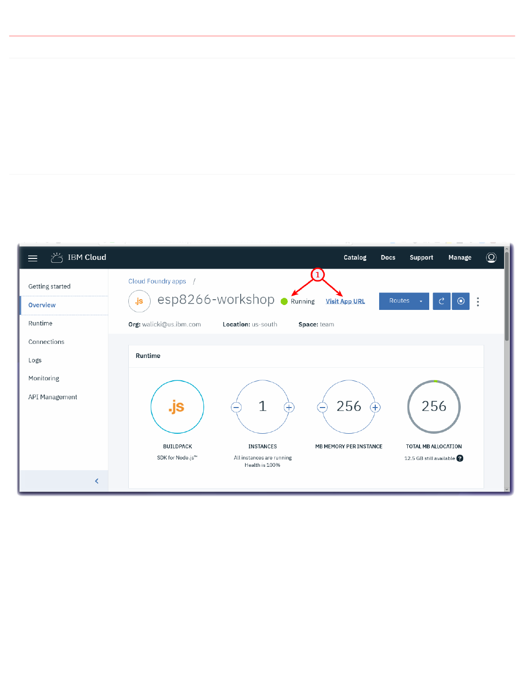
4.2 Node-RED Set up and Configuration in IBM Cloud
4.2.1 Lab Objectives
In this lab you will set up Node-RED in your Watson IoT Starter application created at the end of Part 1. You will learn:
Node-RED Visual Programming
How to secure your Node-RED Editor in IBM Cloud
How to install additional Node-RED nodes
How to import a prebuilt flow from GitHub
4.2.2 Introduction
Node-RED is an open-source Node.js application that provides a visual programming editor that makes it easy to wire together flows.
Step 1 - Node-RED Visual Programming
Recall that in Part 1, you created a IoT Starter Application. Once the application is running, click the View App URL button (1)
•
•
•
•
4.2 Node-RED Set up and Configuration in IBM Cloud
- 61/145 -
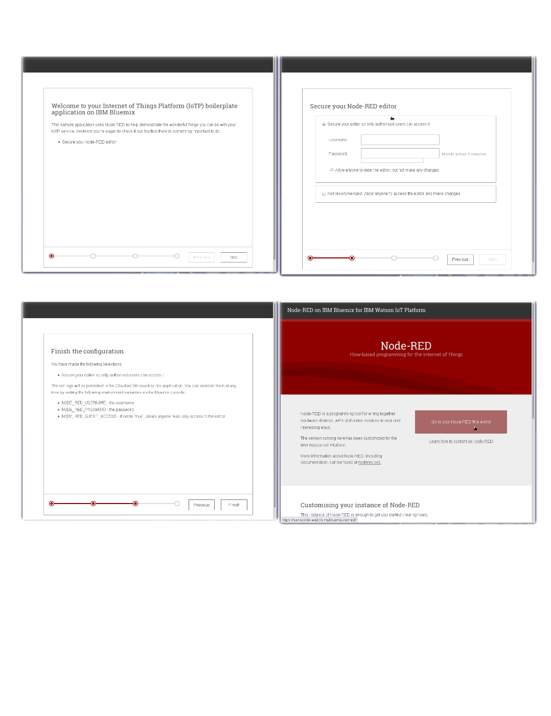
Step 2 - How to secure your Node-RED Editor in IBM Cloud
A new browser tab will open to the Node-RED start page. Proceed through the setup pages by selecting a username / password to access the Node-RED editor.
Remember your username / password. Click the red button Go to your Node-RED flow editor to launch the editor.
4.2.2 Introduction
- 62/145 -
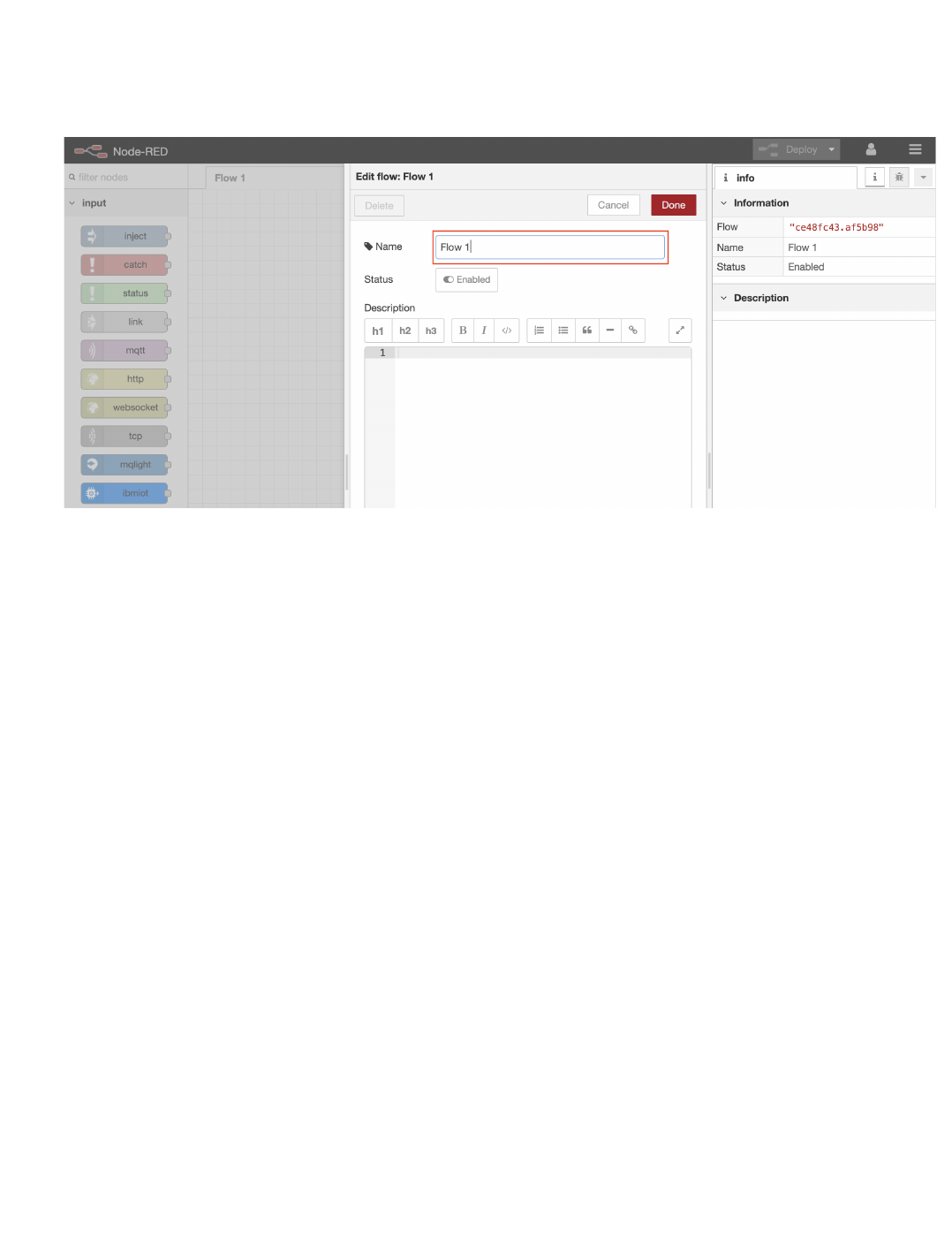
The Node-RED Visual Programming Editor will open with a default flow
On the left side is a palette of nodes that you can drag onto the flow
You can wire nodes together to create a program
Double Click on the Flow 1 tab header
Rename this tab from Flow 1 to Receive ESP8266 Data
Step 3 - How to install additional Node-RED nodes (Information only)
The IoT Starter Application deployed into IBM Cloud includes just a small subset of Node-RED nodes. The Node-RED palette can be extended with over
one thousand additional nodes for different devices and functionality. These NPM nodes can be browsed at http://flows.nodered.org
In part 1 you updated the Application configuration to add the dashboard nodes, you could have also used the Node-RED menu item Manage palette to add
the nodes
Click on the Node-RED Menu (1) in the upper right corner, then Manage palette (2)
•
•
•
•
•
•
•
•
4.2.2 Introduction
- 63/145 -
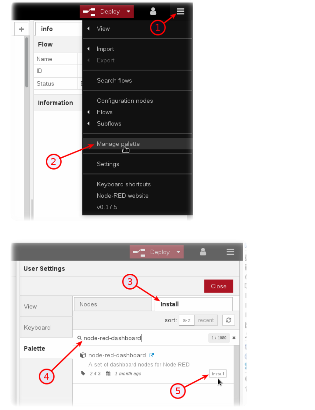
Turn to the Install tab (3), type the name of the node you want to install (4) and press the Install button (5).•
4.2.2 Introduction
- 64/145 -
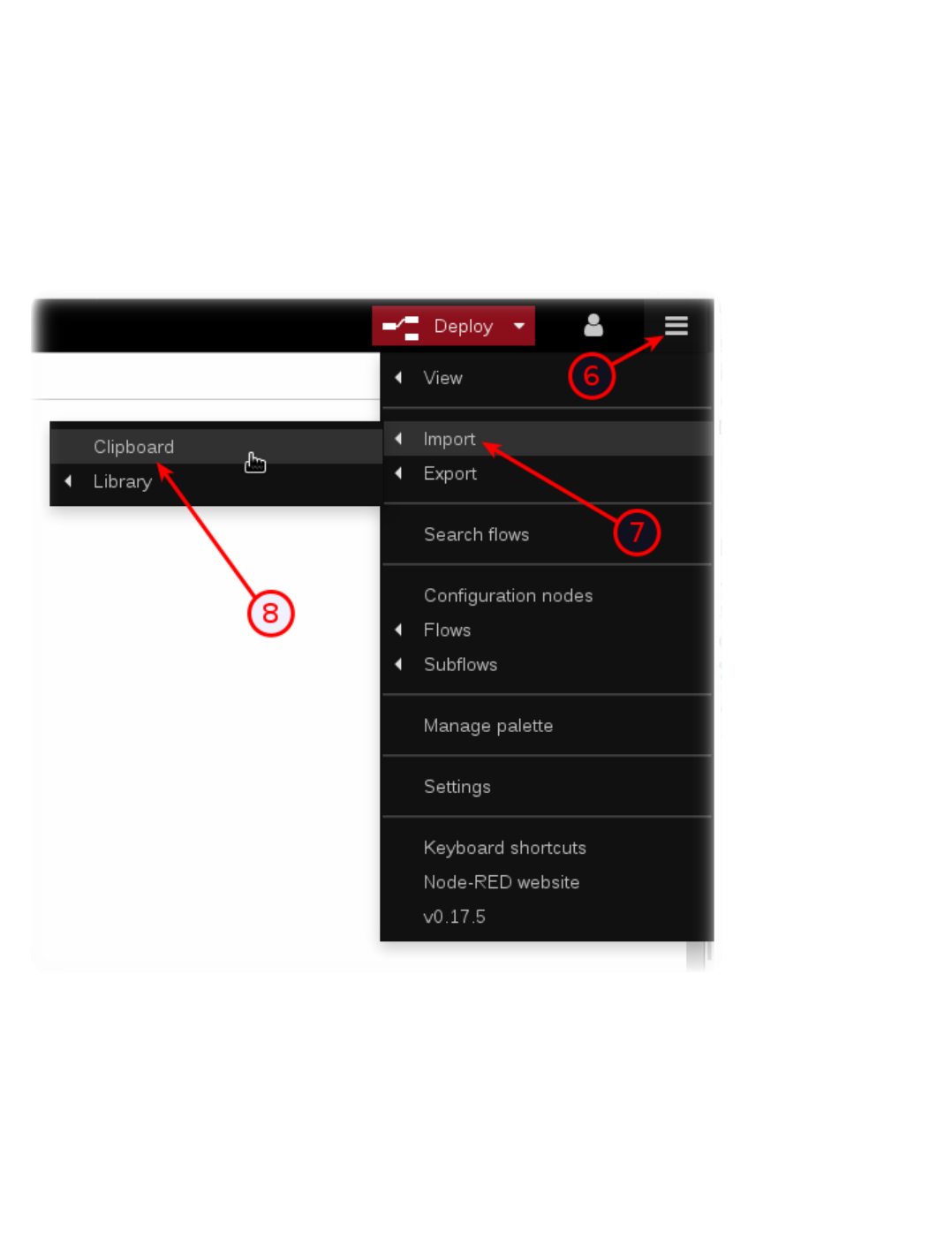
Press the Install button in the next dialog.
Step 4 - How to import a prebuilt flow from GitHub
In this step, you will learn how to Import a prebuilt flow from GitHub
Since configuring Node-RED nodes and wiring them together requires many steps to document in screenshots, there is an easier way to build a flow by
importing a prebuilt flow into your IoT Starter Application.
Not here in Step 4, but in several sections below, there will be a Get the Code link.
When instructed in those later sections, open the Get the Code github URL, mark or Ctrl-A to select all of the text, and copy the text for the flow to your
Clipboard.
Click on the Node-RED Menu (6), then Import (7), then Clipboard (8).
Paste the text of the flow into the Import nodes dialog and press the red Import button.
•
•
•
•
•
•
4.2.2 Introduction
- 65/145 -
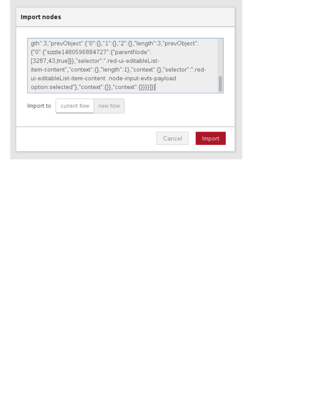
The new flow will be imported into a new tab in the Node-RED Editor.
Click the Deploy button on the top of menu bar to deploy the Node-RED flow.
•
•
4.2.2 Introduction
- 66/145 -

4.3 Receive Device Environmental Sensor Data in Node-RED
4.3.1 Lab Objectives
In this lab you will build a flow that receives Device environmental temperature and humidity sensor data. You will learn:
How to create a new Node-RED flow and configure MQTT Nodes
How to output the Device environmental temperature and humidity data.
How to work with JSON data and observe the sensor results in the Debug sidebar.
4.3.2 Introduction
In just a few nodes, Node-RED can receive the data that was transmitted from the device over MQTT to Watson IoT Platform. This simple exercise will be the
foundation for the next several sections that plot the data in a dashboard, trigger Real Time threshold alerts, store the data in Cloud Storage and allow for data
analytics and anomaly detection.
4.3.3 MQTT Application connections
In part 2 you connected the ESP8266 application to the IoT platform using an MQTT client. In this section you will connect a Node-RED application to the IoT
platform.
The IoT platform uses the open source MQTT protocol to allow devices an applications to connect to the IoT platform, however, it adds some additional security
and restrictions over those defined by the MQTT standard.
Connection types
In part 2 you defined a device type and created a device on the platform to represent your ESP8266 board. The connection was created as a device.
In this section you will connect the Node-RED application as an application connection. Application connections have greater access than a device connection.
Device connections can only produce events and consume commands as the registered device. Gateways are a special type of device connection with additional
privileges that can act on behalf of other devices if they are authorised.
Application connections can consume events from all devices, publish events on behalf of a devices and send commands to devices.
The client ID sent as part of the connection request must include a client ID, which is of a fixed format :
Application : a:orgId:appId
Scalable application : A:orgId:appId
Device : d:orgId:deviceType:deviceId
Gateway : g:orgId:typeId:deviceId
Topics
The IoT platform restricts the topic space used by MQTT. If you attempt to use an invalid topic your connection will be terminated. The valid topics are specified
in the IoT platform documentation but for this section the 2 topics you need to know about are:
Subscribing to device events : iot-2/type/device_type/id/device_id/evt/event_id/fmt/format_string
Publishing device commands : iot-2/type/device_type/id/device_id/cmd/c ommand_id/fmt/format_string
where device_type, device_id, event_id, command_id and format_string are set accordingly.
When subscribing to topics the wildcard character + can be used to subscribe to all events of from any device type, device, event type or format.
•
•
•
•
•
•
•
•
•
4.3 Receive Device Environmental Sensor Data in Node-RED
- 67/145 -
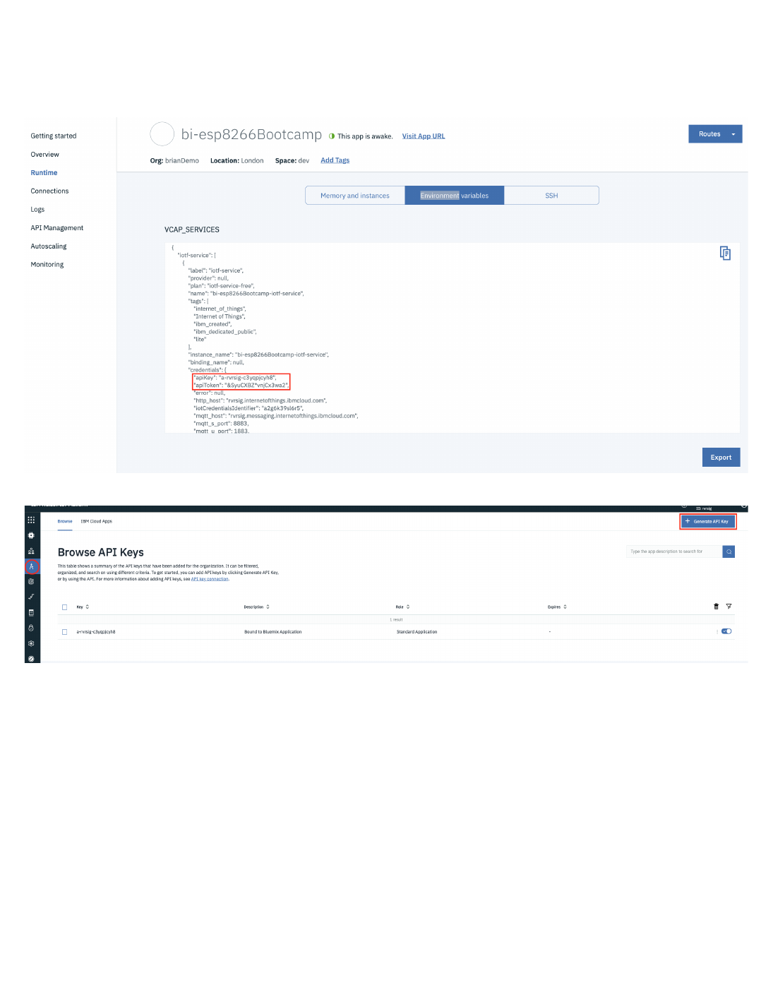
Authentication
In part 2 you needed to register your device to get the token to authenticate against. With an application you need to use and API key and API token to
authenticate.
When the IoT platform is bound to a CloudFoundry application on the IBM Cloud a API key and token are automatically generated and can be seen in the
Runtime environment variable section of the application view on the IBM Cloud web user interface
You can use the automatically generated values or create your own from the App section of the IoT Platform web console
If generating your own key you must take a note of the token as, like the device token, once the screen showing the token is closed it is not recoverable.
The API Key is used as the username when connecting and the API Token is the password.
Custom Certificates
If you have a custom server certificate configured on the IoT platform then you must use the SNI (Server Name Indication) extension to the TLS protocol to
specify the server name in the connection parameters or the IoT platorm will not use your custom certificate.
4.3.3 MQTT Application connections
- 68/145 -

4.3.4 Create the Node-RED flow to receive device events
Step 1 - Configure an MQTT in Node
4.3.4 Create the Node-RED flow to receive device events
- 69/145 -
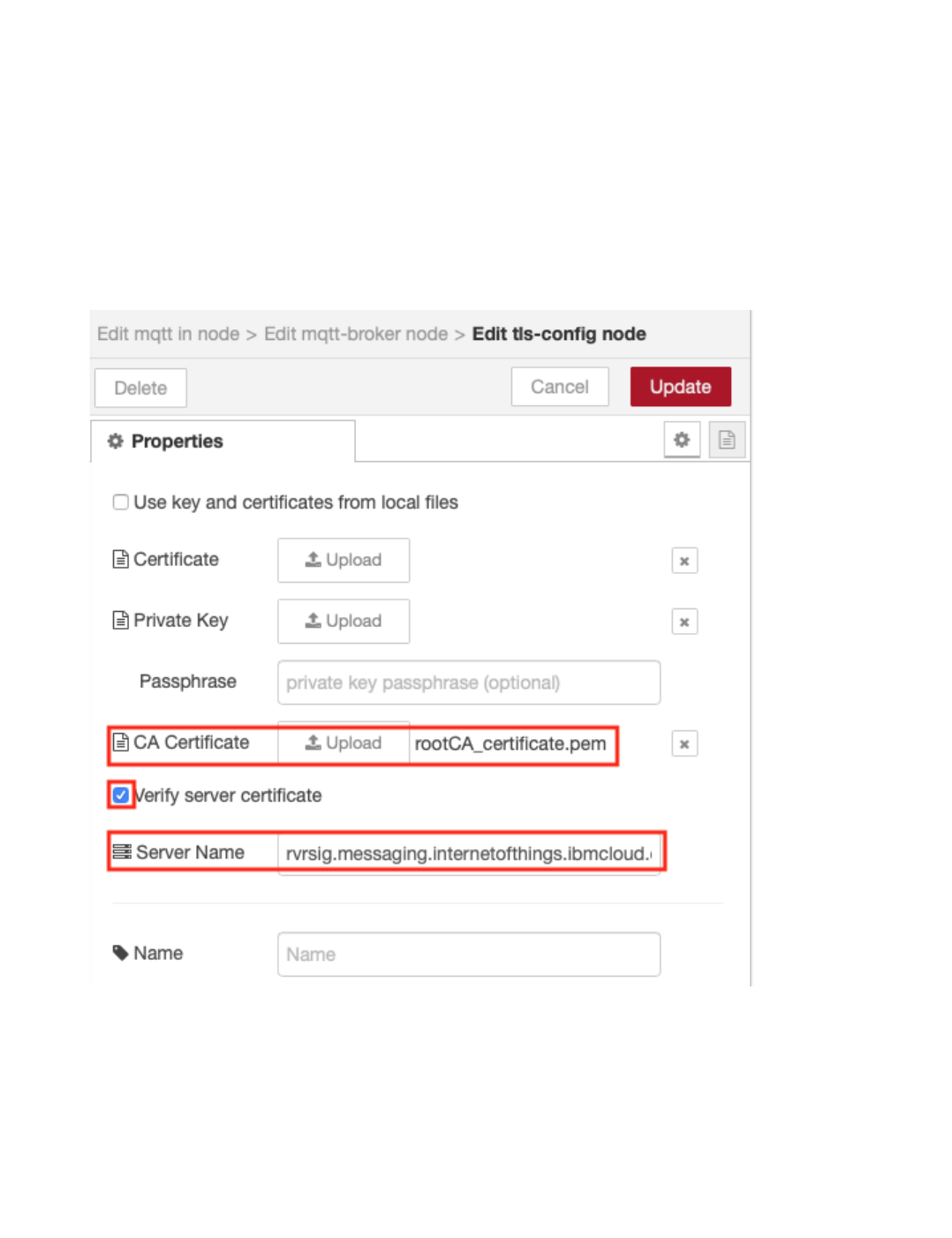
From the Input category of the left Node-RED palette, select an mqtt in node and drag it onto your Node-RED flow.
Double-click on the MQTT node. An Edit mqtt in node sidebar will open.
Click the pencil icon next to the Server property to configure the MQTT server properties - this will open the mqtt-broker node sidebar
Enter the server name in the Server field (orgId.messaging.internetofthings.ibmcloud.com)
Enter 8883 as the Port
Enter the Client ID (a:orgId:appId). The appID can be any unique string
Enable secure (SSL/TLS) connection then select the pencil next to the TLS configuration to open the Edit tls-config node sidebar
Upload the rootCA_certificate.pem file you created in part 2 that is enabled on your server as the CA Certificate
Enable Verify server certificate
Enter the Server Name (orgId.messaging.internetofthings.ibmcloud.com). This sets the SNI extension on the TLS connection
Select Update to close the Edit tls-config node
•
•
•
•
•
•
•
•
•
•
•
4.3.4 Create the Node-RED flow to receive device events
- 70/145 -
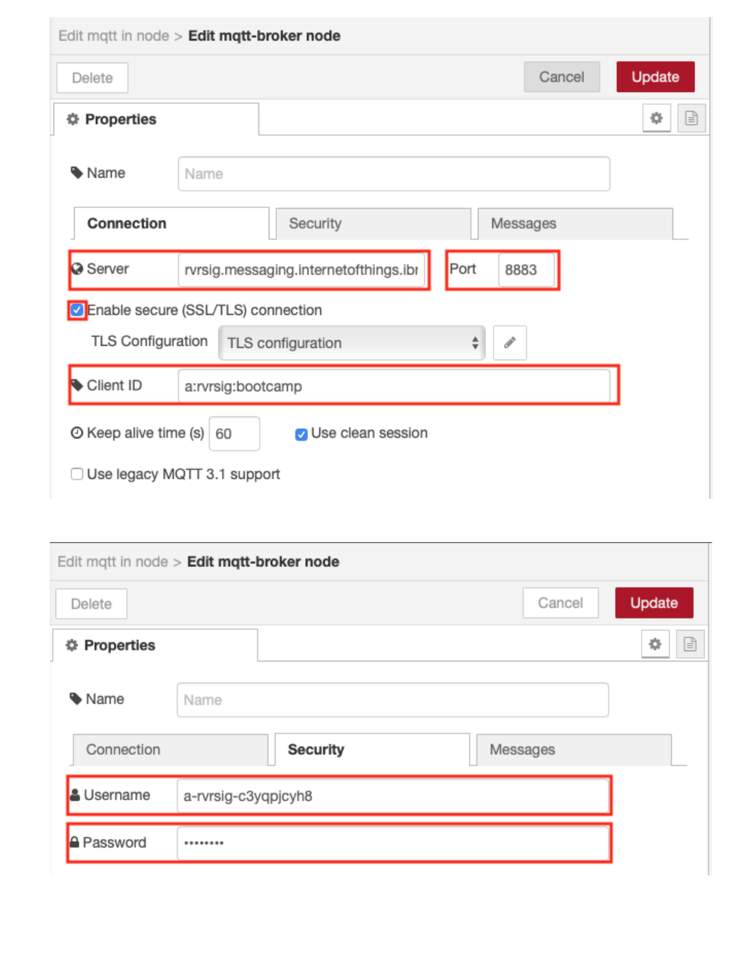
You have finished on the connection tab
Switch to the Security tab and enter the Username and Password - get these from the application runtime environment variables tab of your IBM Cloud
application
press the Update button to return to the Edit mqtt in node sidepanel
Set the topic field to iot-2/type/+/id/+/evt/+/fmt/json. The wildcard + is used to select all events from all devices and all events. The topic requires that the
event contains JSON data.
•
•
•
•
4.3.4 Create the Node-RED flow to receive device events
- 71/145 -
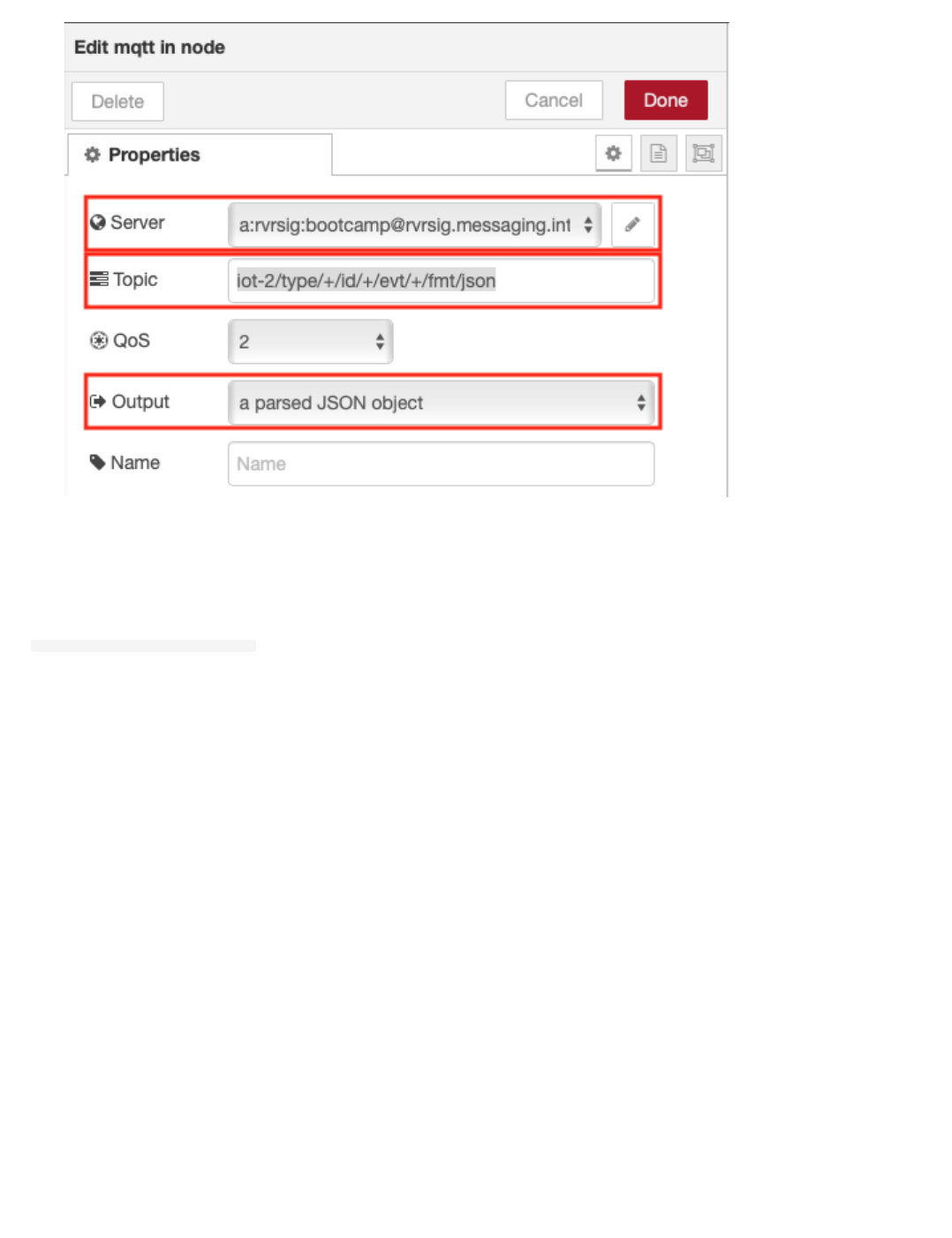
Select the output as a parsed JSON object
Press Done to close the config sidepanel
Step 2 - Extract the Temperature from the JSON Object
Recall that the environmental sensor data was transmitted in a JSON object
{ "d": {"temp":X, "humidity":Y }}
•
•
•
4.3.4 Create the Node-RED flow to receive device events
- 72/145 -
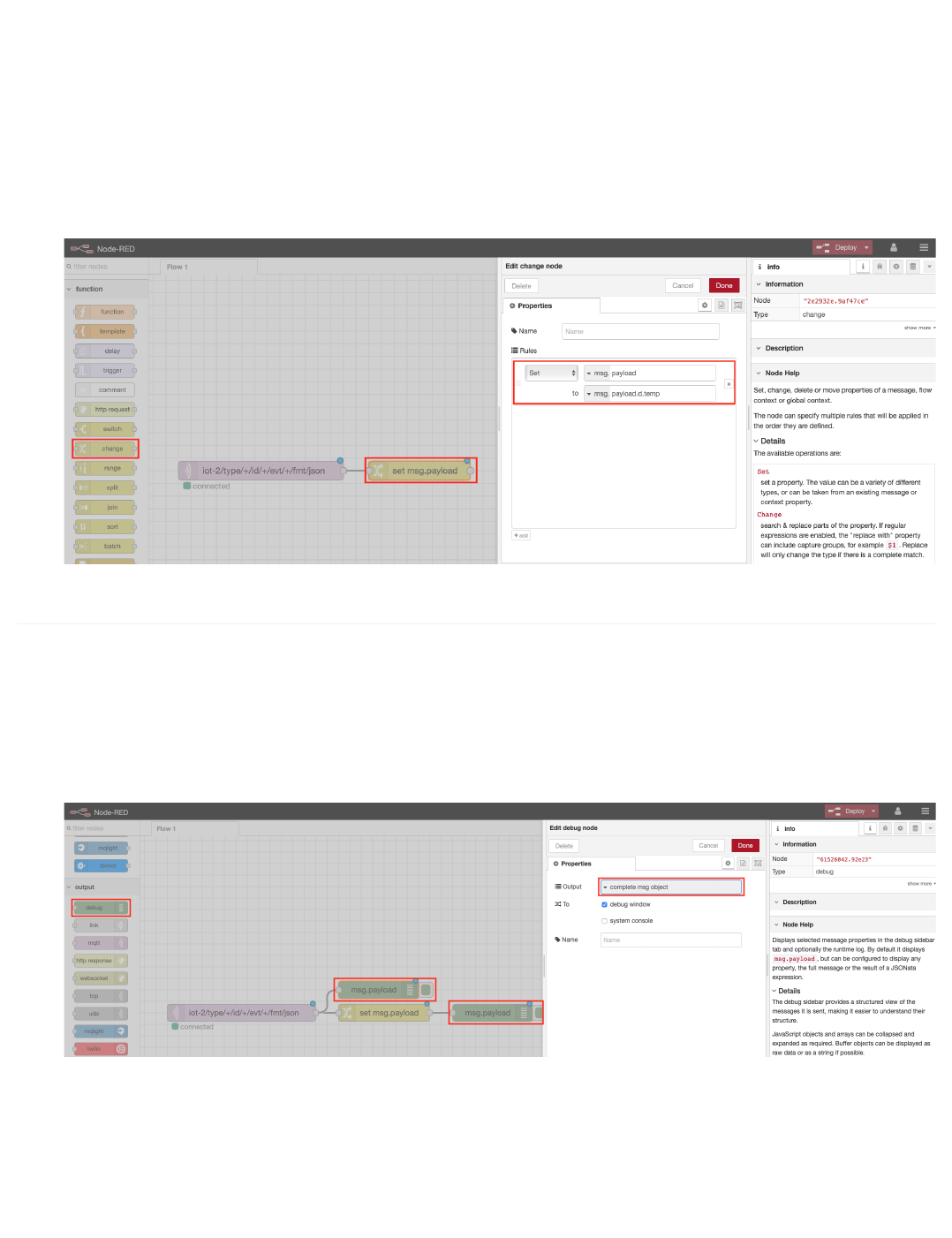
Node-RED passes data from node to node in a msg.payload JSON object.
The Change node can be used to extract a particular value so that it can be directly output or manipulated (for instance in a Dashboard chart which we will
take advantage of in the next section).
From the Function category of the left Node-RED palette, select a Change node and drag it onto your Node-RED flow
Double-click on the Change node. An Edit change node sidebar will open
Configure the "to" AZ dropdown to msg. and set it to payload.d.temp
Click on the red Done button
Wire the node to the MQTT in node by clicking and dragging the connector on the right of the MQTT in node to the connector on the left of the change
node
4.3.5 Step 3 - Node-RED Debug Nodes
Debug nodes can be used to print out JSON object values and help you validate your program.
From the Output category of the left Node-RED palette, drag two debug nodes onto your Node-RED flow (7).
Double-click on one of them. An Edit debug node sidebar will open.
Configure the Output to print the complete msg object (8).
Click on the red Done button.
Wire the 2 nodes as shown
Step 4 - Wire the Node-RED nodes together
•
•
•
•
•
•
•
•
•
•
•
•
•
4.3.5 Step 3 - Node-RED Debug Nodes
- 73/145 -
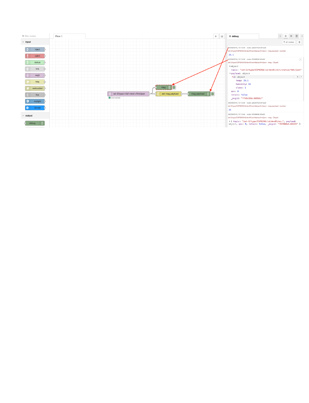
Click on the red Deploy button in the upper right corner.
The mqtt in node should show status Connected
Observe the DHT sensor data in the debug tab of the Node-RED right sidebar. You can expand the twisties to expose the JSON object information. Hover
over a debug message in the right sidebar and the node that generated the message will be outlined in orange.
•
•
•
4.3.5 Step 3 - Node-RED Debug Nodes
- 74/145 -

4.4 Node-RED Dashboard Charts - Plot Environmental Sensor Data
4.4.1 Lab Objectives
In this lab you will import Node-RED flows which create Dashboard Charts. After learning about Node-RED Dashboard Charts, you will be able to display
temperature and humidity graphs of the Device environmental sensors. You will learn:
How to create a Node-RED Dashboard
Experiment with Chart types
Plot Real Time sensor data
Trigger alerts when the real-time sensor data exceeds a threshold value
4.4.2 Introduction
In this section you will learn about Node-RED Dashboard Charts and then create a chart to graph the sensor data arriving from the device.
Step 1 - Add the Dashboard nodes to the Node-RED pallet
Follow the steps outlined in the introduction to Node-RED to import the node-red-dashboard nodes to your Node-RED pallet
From the Node-RED menu (
26
30 ), select Manage Pallet*
Goto the Install tab
Search for the node-red-dashboard nodes
Press the install button to install the nodes
Close the Pallet Manager window when the nodes have been installed
Step 2 - Import the Node-RED Dashboard Chart Flows
Open the “Get the Code” github URL listed below, mark or Ctrl-A to select all of the text, and copy the text for the flow to your Clipboard. Recall from a
previous section, click on the Node-RED Menu, then Import, then Clipboard. Paste the text of the flow into the Import nodes dialog and press the red Import
button. Finally, click on the red Deploy button in the upper right corner.
Node-RED Dashboard Charts : Get the Code
•
•
•
•
•
•
•
•
•
4.4 Node-RED Dashboard Charts - Plot Environmental Sensor Data
- 75/145 -
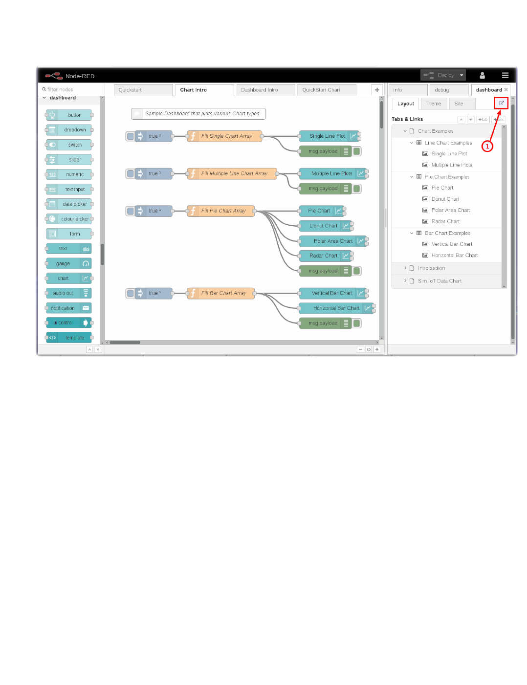
Step 3 - Learn about various Node-RED Dashboard Chart types
You might have noticed that the flow import in the prior step actually created three tabs. These are called Node-RED flows.
The Chart Intro flow introduces you to the various Node-RED Dashboard Chart types that are available. You can create Line charts, various Pie chart
styles – Pie, Donut, Polar Area, Radar - and vertical and horizontal Bar charts.
For illustration, the Fill Single Chart Array function node above fills an array of static sample data and sends the data to the Chart node to visualize.
•
•
•
4.4.2 Introduction
- 76/145 -
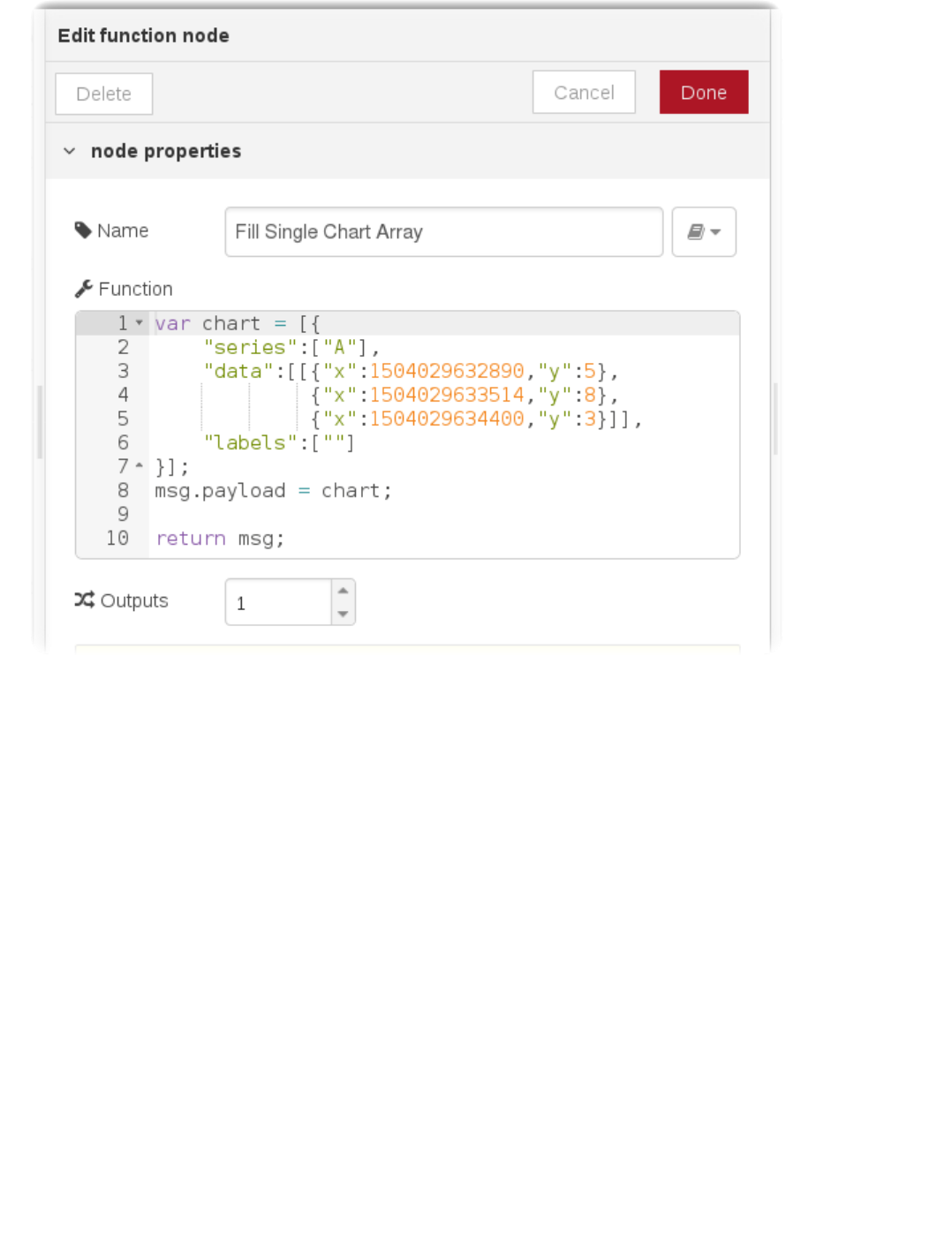
4.4.2 Introduction
- 77/145 -
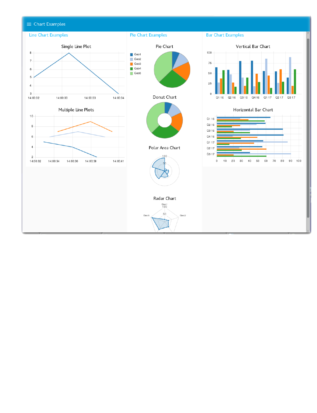
The Node-RED flow is not nearly as interesting as the charts that it renders. To launch the Node-RED Dashboard, in the Node-RED sidebar, turn to the
dashboard tab and click on the Launch button (1) [See two pictures above].
Step 4 – Generating and Displaying data in Node-RED Dashboards
The next Node-RED flow - Dashboard Intro - uses a variety of UI widgets to display data in the Node-RED Dashboard. There is a Switch node that turns On/Off
a random number generator function node. The simple random numbers are sent to a line Chart node, a Gauge node, a Slider node, a Text node and, if the number
exceeds a threshold, will display an alert notification message.
•
4.4.2 Introduction
- 78/145 -
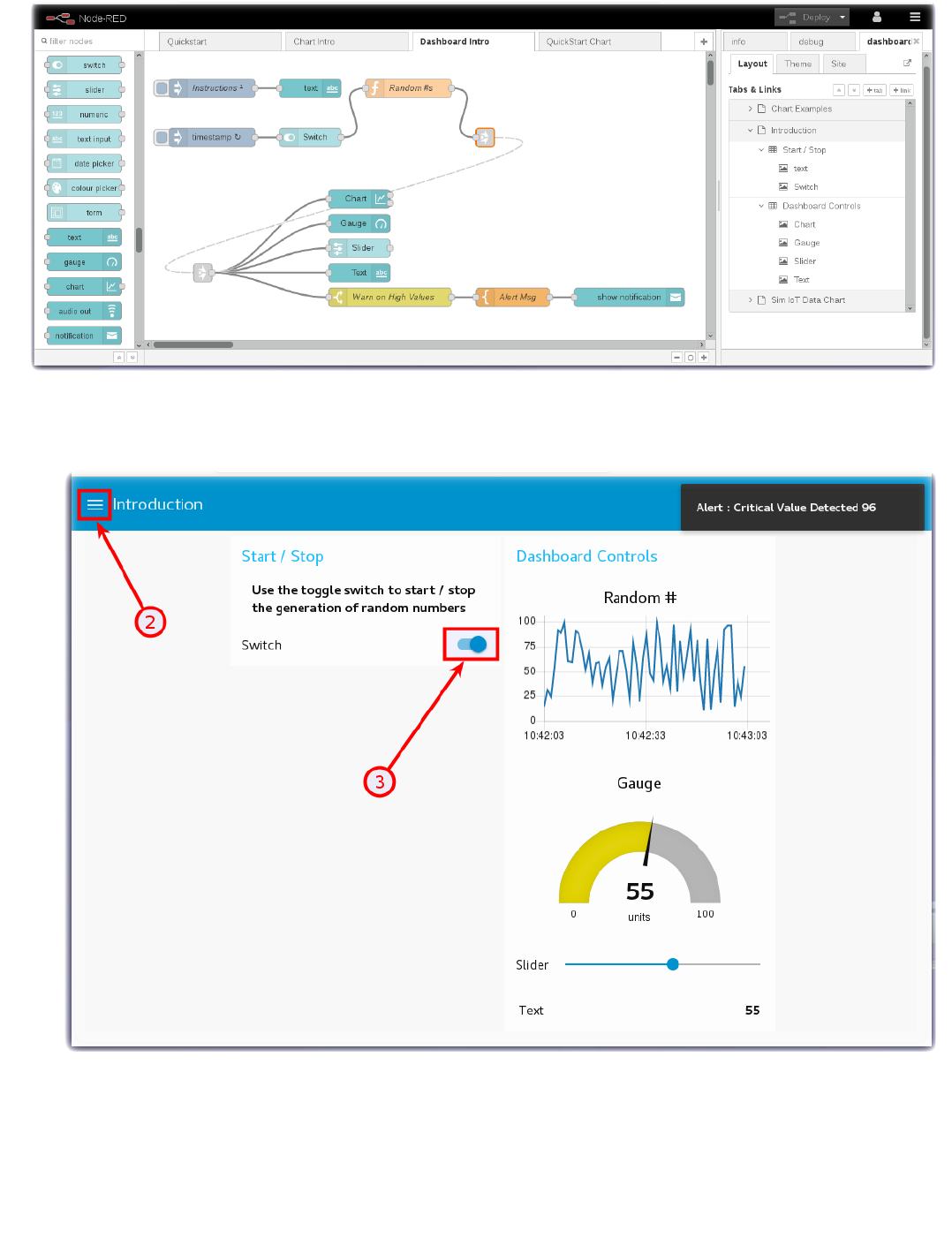
Turn to the Node-RED Dashboard browser tab that you launched in Step 2, click on the menu tab (2) in the upper left corner, and select the Introduction tab.
On the Introduction dashboard, turn on the Switch (3) to start the data visualization.
Experiment with / observe the Dashboard controls.
Step 5 - Plot Device Environmental Sensor Data
Now that you have learned about Node-RED Dashboard and Chart types, you are ready to plot the real-time device environmental sensor data. If you are working
in the lite plan on the IBM Cloud memory is limited, so you may want to delete the tabs Chart Intro and Dashboard Intro by double clicking each tab to open up
the tab configuration sidebar, where you will find a delete button.
•
•
•
4.4.2 Introduction
- 79/145 -
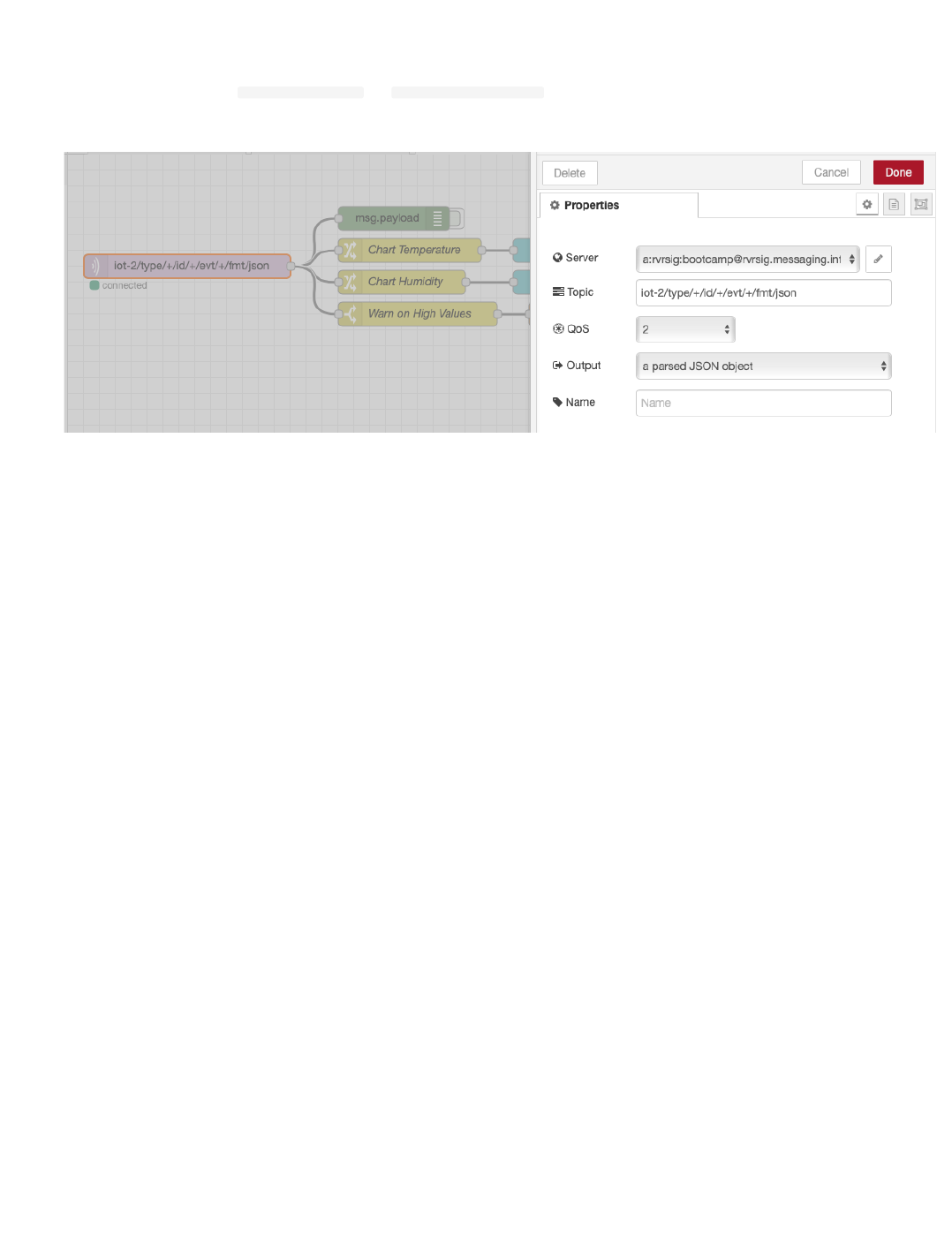
Turn to the next flow - Plot DHT Sensor Data
The mqtt in node may need to be configured to pull in the config you created in the previous section.is already configured to receive status Device Events
from the ESP8266 Device Type.
The Change nodes extract the
msg.payload.d.temp and msg.payload.d.humidity values from the JSON object sent over MQTT from the device
environmental sensor to Watson IoT Platform.
The environmental sensor values are sent to two charts to plot Temperature and Humidity.
Turn to the Node-RED Dashboard browser tab that you launched in Step 2, click on the tab in the upper left corner, and select the ESP8266 Workshop tab.
•
•
•
•
•
4.4.2 Introduction
- 80/145 -
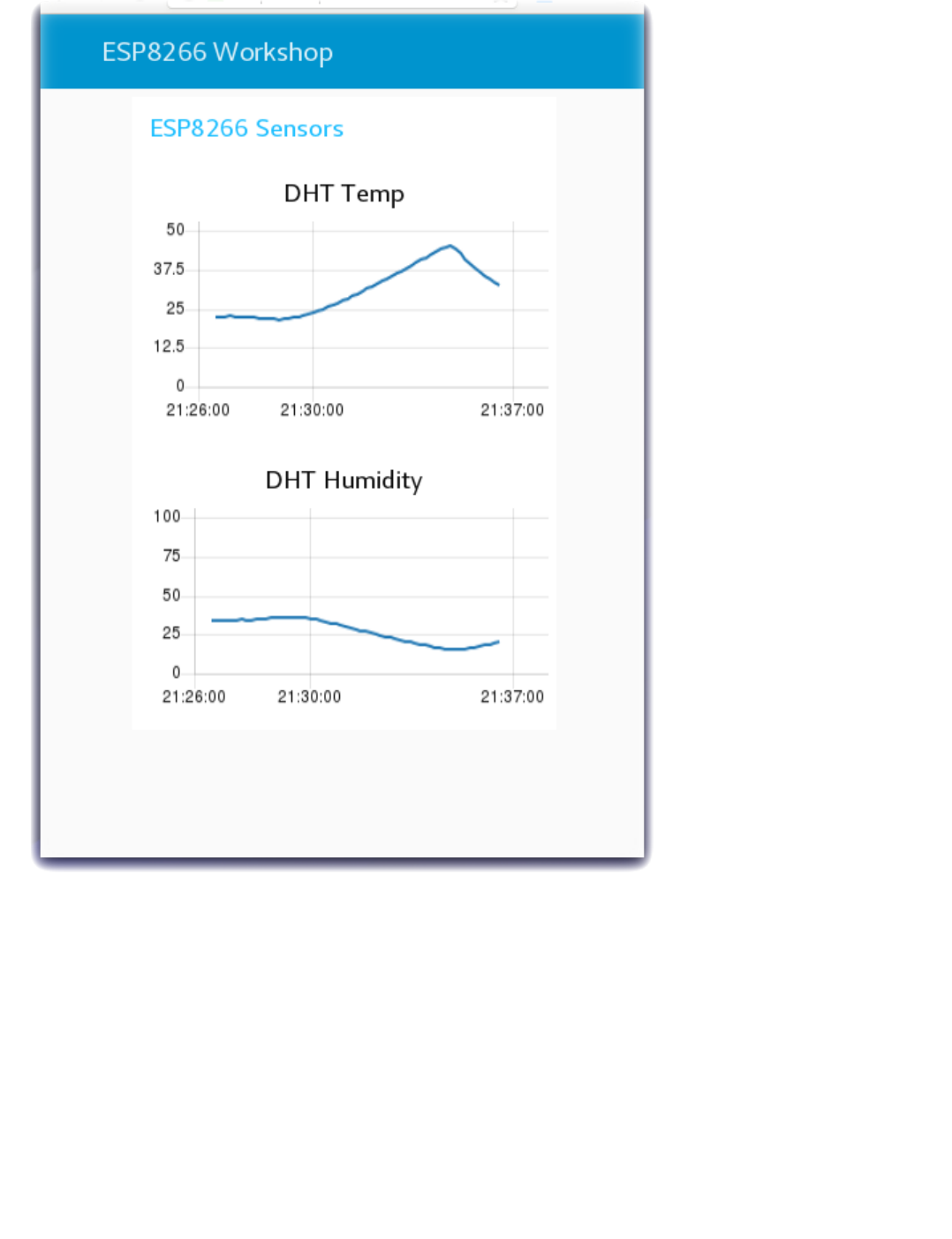
4.4.2 Introduction
- 81/145 -
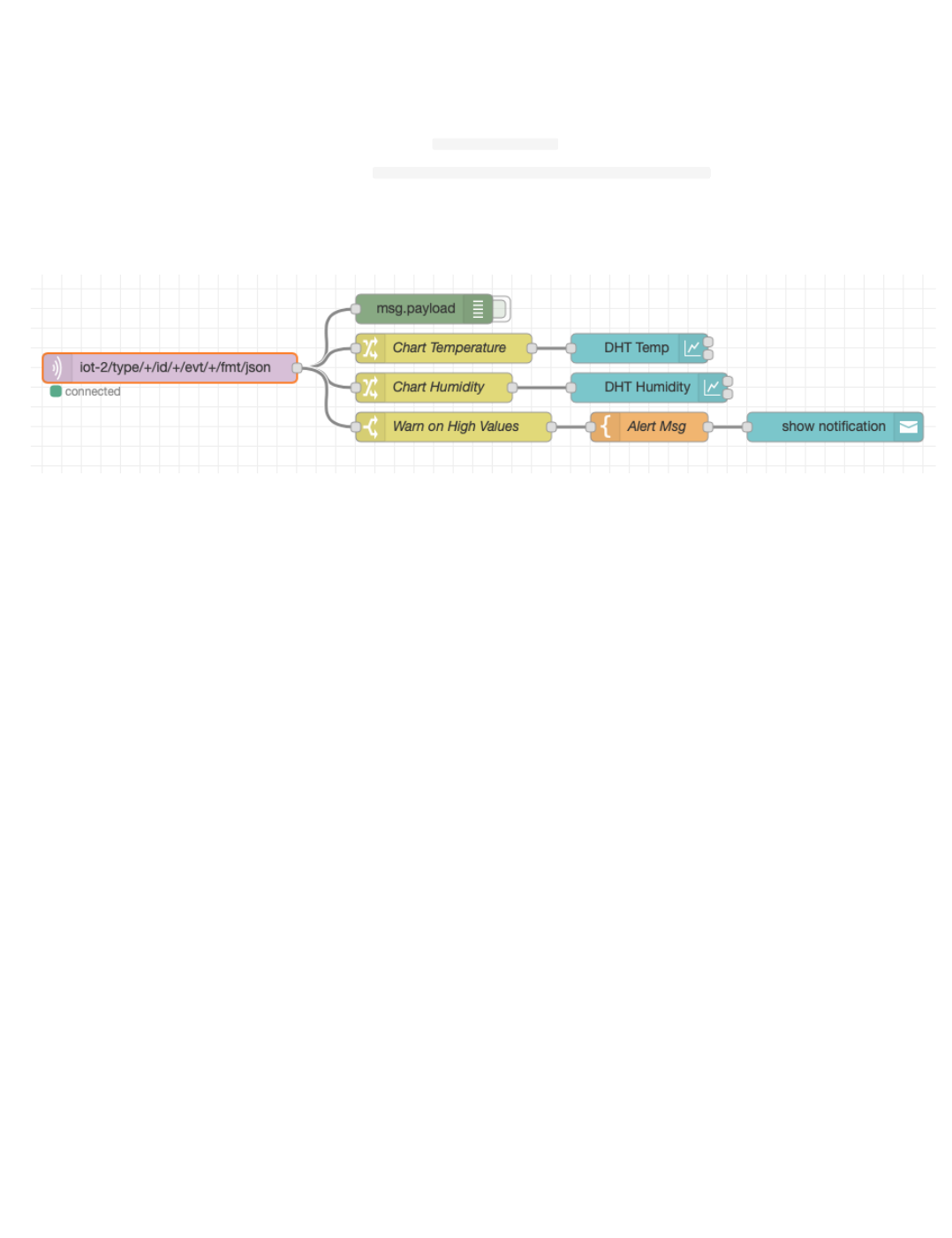
Step 6 - Trigger Alerts when Real-Time Sensor Data Exceeds a Threshold Value
Often IoT devices and sensors are deployed so that alerts can be triggered when the real time sensor data exceeds a threshold value. In this last Step, the flow
checks the temperature values and, if the temperature exceeds the threshold, triggers a Node-RED Dashboard notification.
In the prior step, the flow included three nodes that have not yet been discussed.
A Switch node is configured to Warn on High Values by testing if
msg.payload.d.temp is greater than 30C.
A Template node is configured to construct a sentence Alert : Critical Value Detected {{payload.d.temp}}
The Alert message is sent to a Node-RED Dashboard Notification node to display in the browser.
This flow could be extended to call a Twilio node to send a SMS message. It could raise an alarm in another system by triggering a REST API call to the
manufacturing production operations systems.
Return to the Node-RED Dashboard ESP8266 Workshop tab and increase the temperature of your DHT sensor above 30C.
•
•
•
•
•
•
4.4.2 Introduction
- 82/145 -
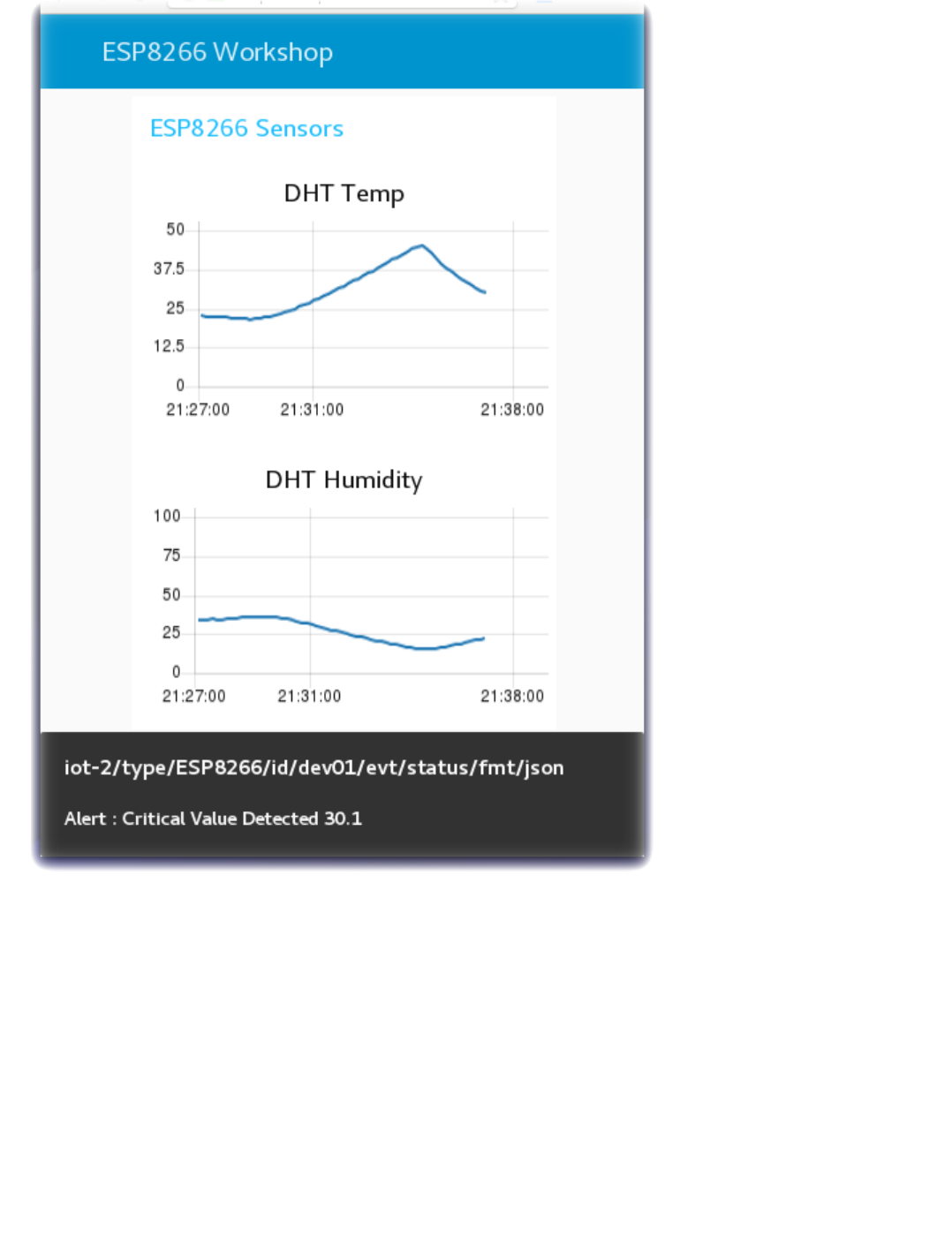
4.4.2 Introduction
- 83/145 -

4.5 Store Data in Cloud Storage for Historical Data Analytics
4.5.1 Lab Objectives
In this lab you will store the device environmental sensor data in a Cloudant database in IBM Cloud. You will learn:
How to create a Node-RED flow that uses the Cloudant node
How to format a time series database record
How to view Cloudant databases
4.5.2 Introduction
While real-time charts of sensor data and threshold alerts are useful, the power of IoT becomes significant when data analytics techniques, Machine Learning and
AI are applied to the IoT historical datasets. The first and necessary step toward data analytics is storing the incoming data in a Cloud data storage database for
later statistical modelling.
Step 1 - Import the Node-RED Cloudant Storage Flow
Open the “Get the Code” github URL listed below, mark or Ctrl-A to select all of the text, and copy the text for the flow to your Clipboard. Recall from a
previous section, click on the Node-RED Menu, then Import, then Clipboard. Paste the text of the flow into the Import nodes dialog and press the red Import
button.
Node-RED Cloud Storage Flow : Get the Code
You will need to verify the configuration of the mqtt in node to use your configuration, as you did in the previous section.
•
•
•
4.5 Store Data in Cloud Storage for Historical Data Analytics
- 84/145 -
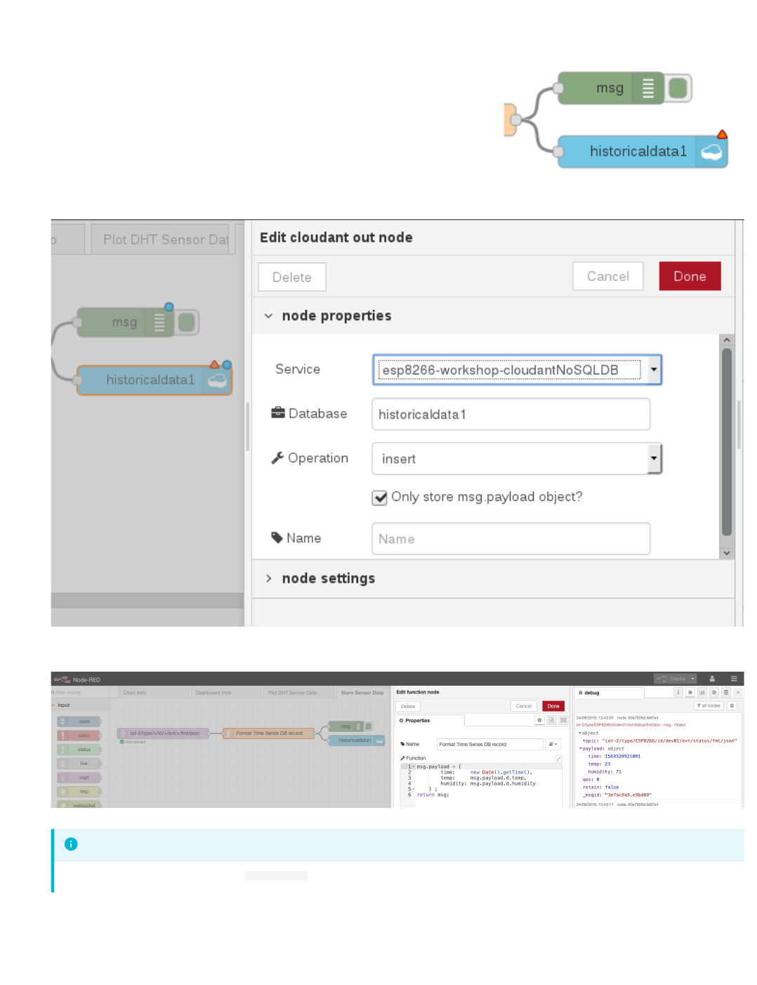
Step 2 - Store IoT Sensor Data with Node-RED
In this Step you will use Node-RED to store IoT Sensor data from the ESP8266 DHT environmental sensors in a Cloudant database.
When the flow is imported there will be a misconfigured Cloudant node – indicated by a red triangle.
To associate the Cloudant database node with your IBM Cloud instance, double-click on the historical data Cloudant node and press the red Done button.
The red error triangle will turn blue.
The Format Time Series DB Record function node recasts the ESP8266 DHT JSON object. As required by any time series dataset, the Node-RED function
node adds a timestamp to the record before writing it to the Cloudant storage.
Click the Deploy button on the top of menu bar to deploy the Node-RED flow.
The device environmental sensor data is now being recorded in a Cloudant database.
•
•
•
in the screenshot, the debug sidebar shows a
msg.payload
that includes the Epoch timestamp (milliseconds since Jan 1 1970)
Info
•
•
4.5.2 Introduction
- 85/145 -

Step 3 - Observe Sensor Data being added to the Cloudant database
4.5.2 Introduction
- 86/145 -
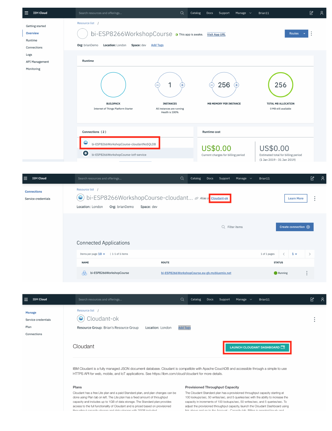
Return to the IBM Cloud dashboard and your IoT Starter application. Click on the cloudantNoSQLDB service connection:
The database linked to your application is an alias link to the actual database instance, so select the link to get to the actual database instance:
Read about the Cloudant Storage service and press the Launch button:
•
•
•
4.5.2 Introduction
- 87/145 -
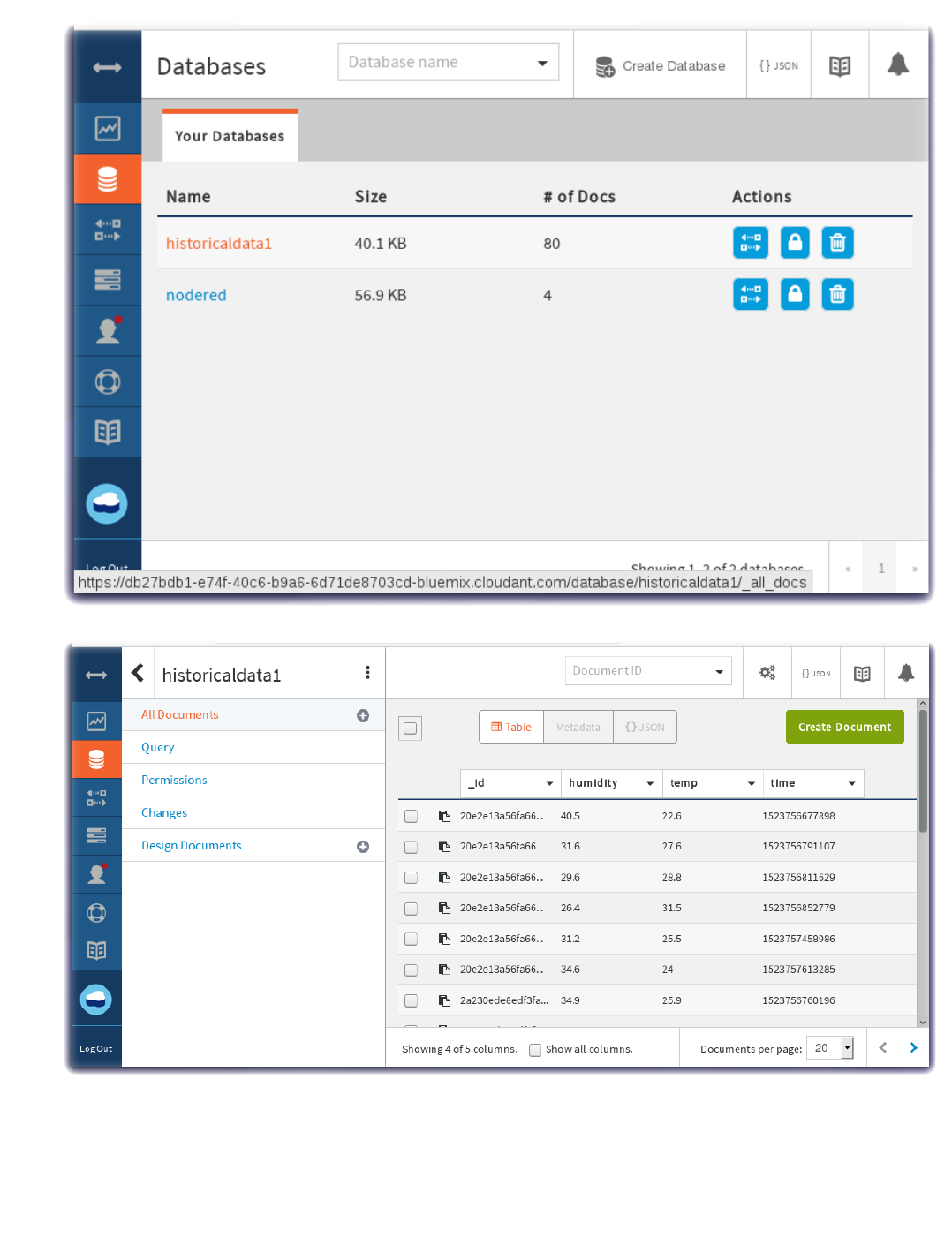
The IoT Sensor device data is stored in the Cloudant service.
Click on historicaldata1 and then observe the Table view of temperature, humidity and timestamp data:
•
•
4.5.2 Introduction
- 88/145 -
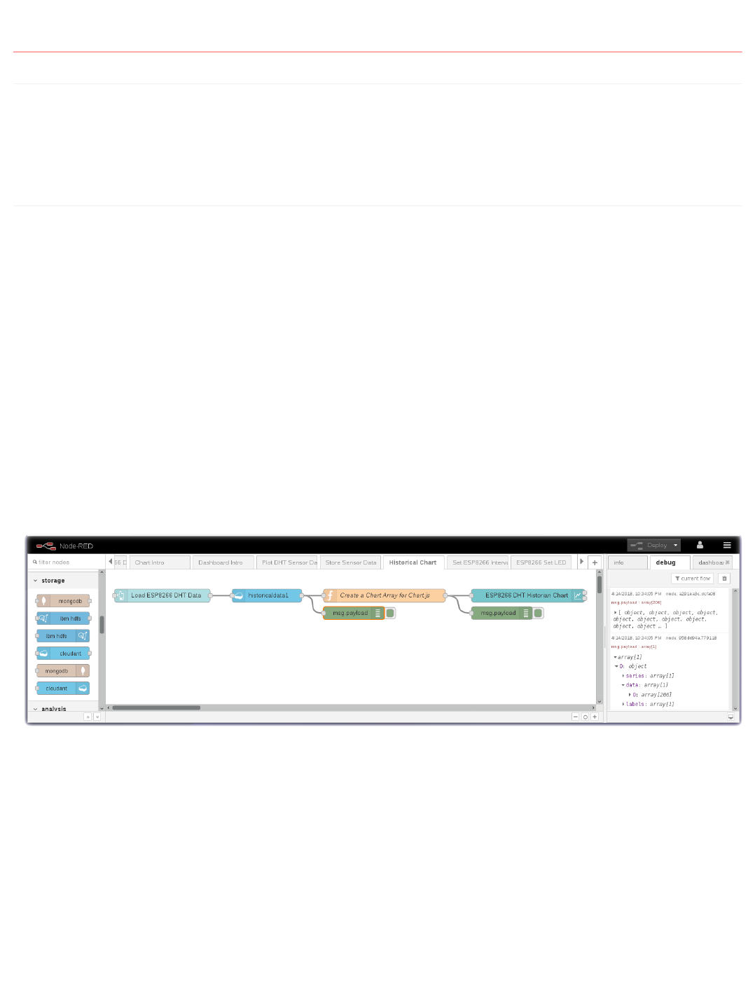
4.6 Node-RED Charts of Historical Sensor Data
4.6.1 Lab Objectives
In this lab you will read the historical sensor data from a Cloud storage database and create a graph of prior readings. You will learn:
How to read datasets from a Cloudant database
How to create a chart of historical data
4.6.2 Introduction
The previous section stored the Device environment sensor data into a Cloudant DB. This section will read the historical sensor data from a Cloud storage
database and create a graph of prior readings.
Step 1 - Import the Node-RED Historian Chart Flow
Open the “Get the Code” github URL listed below, mark or Ctrl-A to select all of the text, and copy the text for the flow to your Clipboard. Recall from a
previous section, click on the Node-RED Menu, then Import, then Clipboard. Paste the text of the flow into the Import nodes dialog and press the red Import
button.
Node-RED Historian Chart Flow : Get the Code
Click on the Cloudant node on the Historical Chart flow to confirm that it is configured to your IoT Platform Cloudant service instance.
Click the Deploy button on the top of menu bar to deploy the Node-RED flow.
Step 2 - Graph Historical IoT Sensor data stored in a database using Node-RED
The Historical Chart flow reads the IoT Sensor Device data from the Cloudant database and formats it into a Chart array before sending the data to a Node-
RED Chart node.
•
•
•
•
•
•
4.6 Node-RED Charts of Historical Sensor Data
- 89/145 -
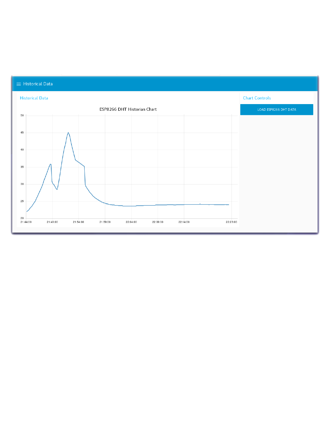
Step 3 - Historian Charts of Device Environmental Sensor data
Turn to the Node-RED Dashboard browser tab, click on the menu tab in the upper left corner, and select the Historical Data tab.
On the Historical Data dashboard, click on the LOAD ESP8266 DHT DATA button to start the data visualization.
The button will trigger the read of the historian DB records created in the previous section.
In the Create a Chart Array for Chart.js function node the time series temperature data from the Device Environmental sensor is formatted into a Chart
Array and sorted chronologically.
The Chart Array is passed to the Node-RED Chart node to render the graph.
•
•
•
•
•
4.6.2 Introduction
- 90/145 -
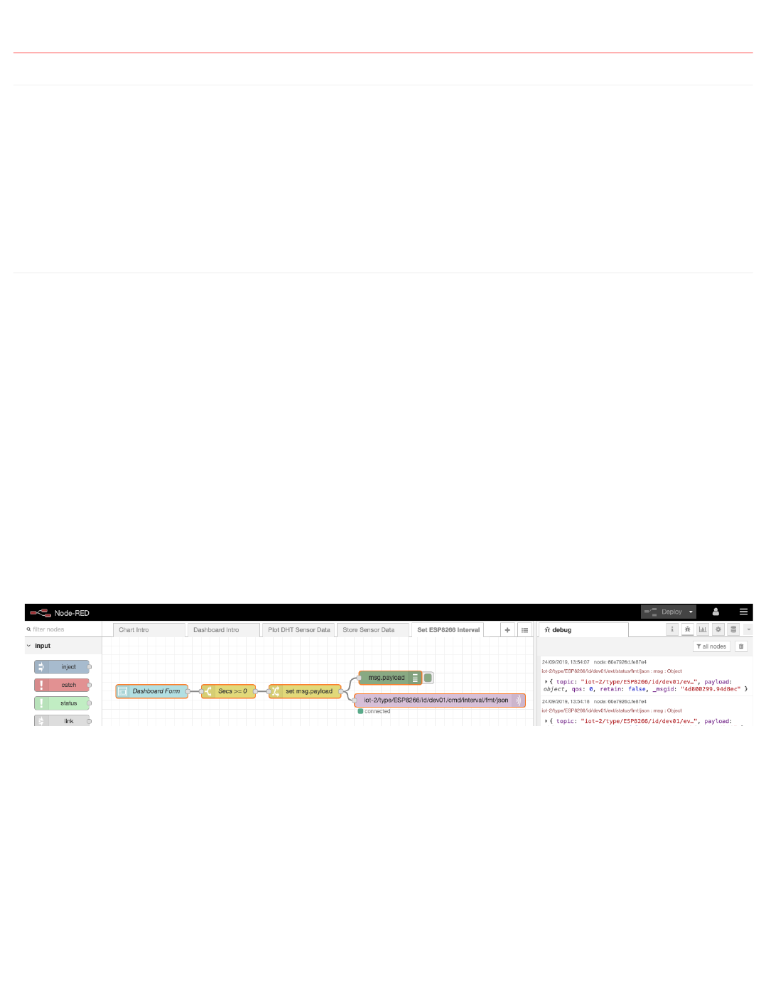
4.7 Control your Device reporting interval via a Node-RED Dashboard Form
4.7.1 Lab Objectives
In this lab you will modify the ESP8266 Arduino program to receive MQTT commands from the IBM Cloud and build a Node-RED Dashboard Form to
dynamically change the reporting interval of the ESP8266 DHT environmental sensor data. You will learn:
How to build a Node-RED Dashboard Form
How to send MQTT commands from the IBM Cloud to your ESP8266
How to receive MQTT commands within your ESP8266 Arduino program / sketch.
How to work with JSON data on the ESP8266
4.7.2 Introduction
Remote management and control of IoT Devices is critical to managing the flow of sensor data to the Cloud. The IoT Device might only need to check in
occasionally during quiet periods of inactivity. Waking up the device and requesting that it report sensor data more frequently during active time periods is better
for power management, bandwidth consumption and cloud storage.
This section will build a Node-RED Dashboard Form where you can enter a new reporting interval. A MQTT command will be published from the IBM Cloud to
the ESP8266 device. The ESP8266 will receive the interval update and adjust how often it transmits the DHT environmental sensor data.
Step 1 - Import the Node-RED Dashboard Reporting Interval Form Flow
Open the “Get the Code” github URL listed below, mark or Ctrl-A to select all of the text, and copy the text for the flow to your Clipboard. Recall from a
previous section, click on the Node-RED Menu, then Import, then Clipboard. Paste the text of the flow into the Import nodes dialog and press the red Import
button.
Node-RED Dashboard Reporting Interval Form Flow Get the Code:
Turn to the Set ESP8266 Interval flow tab.
Fix the configuration of the mqtt in node
Click the Deploy button on the top of menu bar to deploy the Node-RED flow.
•
•
•
•
•
•
•
•
4.7 Control your Device reporting interval via a Node-RED Dashboard Form
- 91/145 -
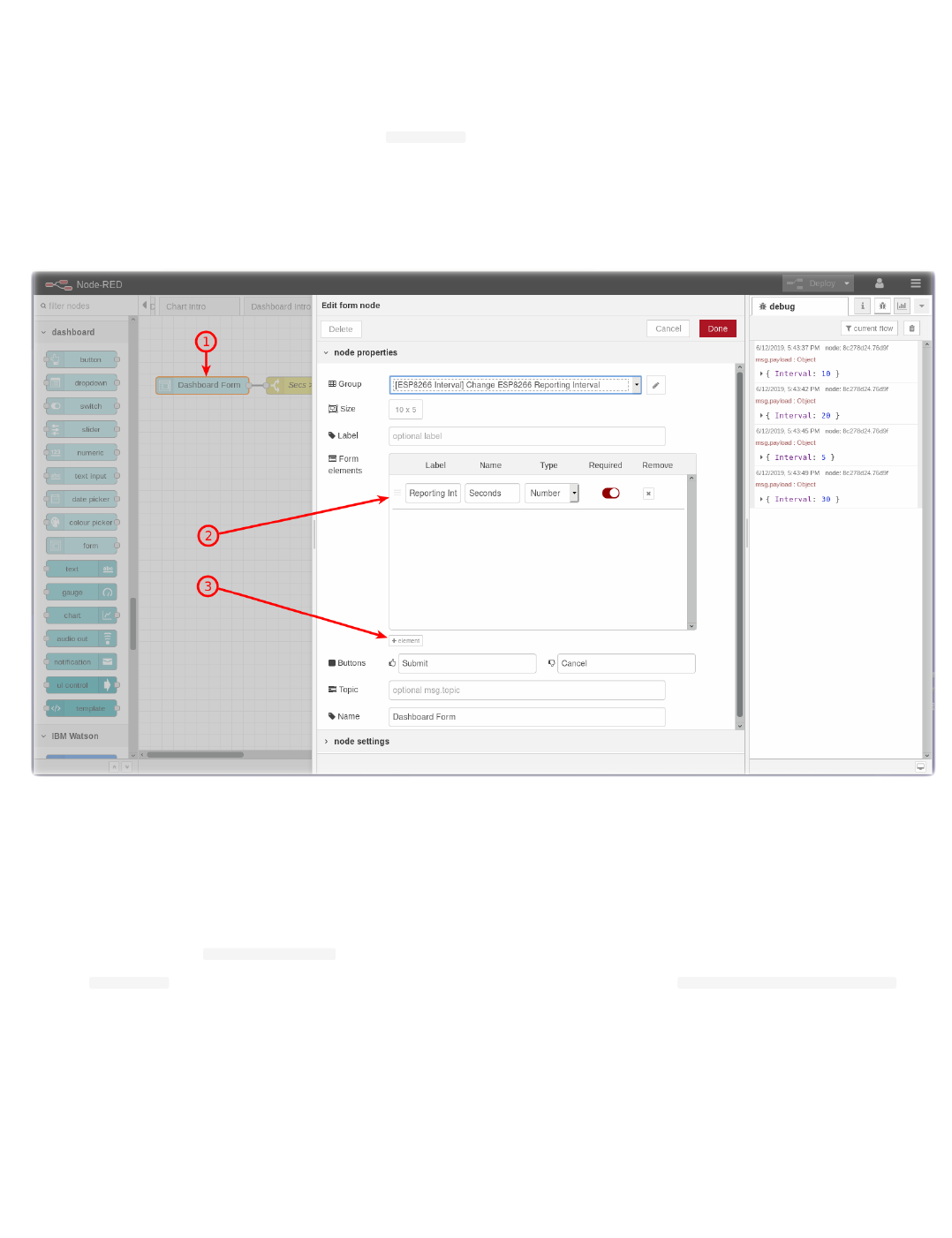
Step 2 - Node-RED Dashboard Form node
The Node-RED Dashboard Form node can be customized to query user input fields - text, numbers, email addresses, passwords, checkboxes and switches.
Sophisticated forms can be constructed in one Node-RED Dashboard Form node.
After entering the form data, the user can press Submit or Cancel buttons.
When the Submit button is pressed the flow constructs a
msg.payload JSON Object with the values entered.
Double-click on the Dashboard Form node (1). An Edit form node sidebar will open.
This form only has one element (2). It asks in a field labelled Reporting Interval for a numeric value. This value will be stored in a variable named Seconds
You might experiment by adding additional elements (3) that could prompt for Text, Numbers, validated email addresses, Passwords (which will be masked
when input as * ), Checkmarks or Switches.
Press the Cancel button when you have finished experimenting with the form node.
Step 3 - Description of the Set ESP8266 Interval flow
The Set ESP8266 Interval flow contains just 5 nodes.
The Dashboard Form node queries the user for a new interval value.
The result is passed in a msg.payload.Seconds JSON Object to a Switch node which tests if the number entered is equal to or greater than Zero.
The msg.payload is reformatted in a Change node using the JSONata Expression editor into a JSON Object {"Interval":msg.payload.Seconds}
The resulting JSON Object is passed to an mqtt out node.
The topic configured in the mqtt out node specifies the device to receive the command.
Step 4 - Send MQTT Commands using the MQTT Out Node
•
•
•
•
•
•
•
•
•
•
•
•
•
4.7.2 Introduction
- 92/145 -
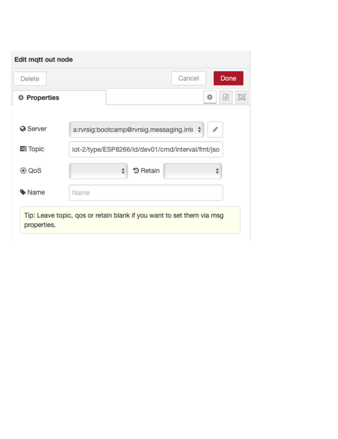
Double-click on the IBM IoT node (4). An Edit mqtt out node sidebar will open.
The mqtt out node is configured to send a Device Command (5) to your ESP8266 Device Id by using the appropriate topic. The target device is identified
as part of the topic
The Command Type will be named interval and is also set in the topic
Press the red Done button.
•
•
•
•
4.7.2 Introduction
- 93/145 -
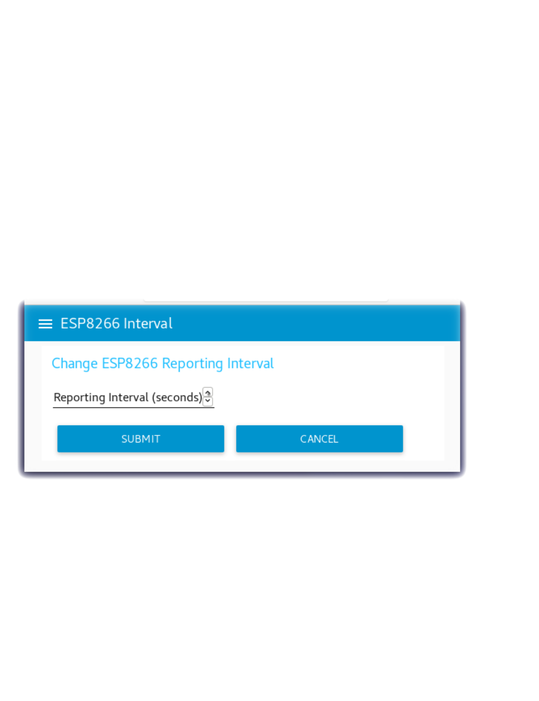
Step 5 - Reprogram the ESP8266 to subscribe to MQTT Commands
Open the “Get the Code” github URL listed below, mark or Ctrl-A to select all of the text, and copy the text for the replacement ESP8266 program.
IoT Workshop Arduino Program : Get the Code
Return to the Arduino IDE
Record your Watson IoT connection details from the top of your version of the existing IoTWorkshop.ino you created in Part 2.
Replace the source code with the above.
This version registers a callback and subscribes to MQTT Device Commands.
The program loops but polls for MQTT incoming Commands.
If a Interval command is sent, it updates how long it should sleep before sending the next DHT environmental sensor data.
Merge in your Watson IoT connection details.
Compile and Flash this updated program to the ESP8266
Step 6 - Node-RED Dashboard Reporting Interval Form
Turn to the Node-RED Dashboard browser tab, click on the menu tab in the upper left corner, and select the ESP8266 Interval tab.
On the ESP8266 Interval dashboard, click on the form and enter a new value.
Click on the SUBMIT button.
The button will trigger the flow to send the new value to the ESP8266 over MQTT.
•
•
•
•
•
•
•
•
•
•
•
•
•
4.7.2 Introduction
- 94/145 -
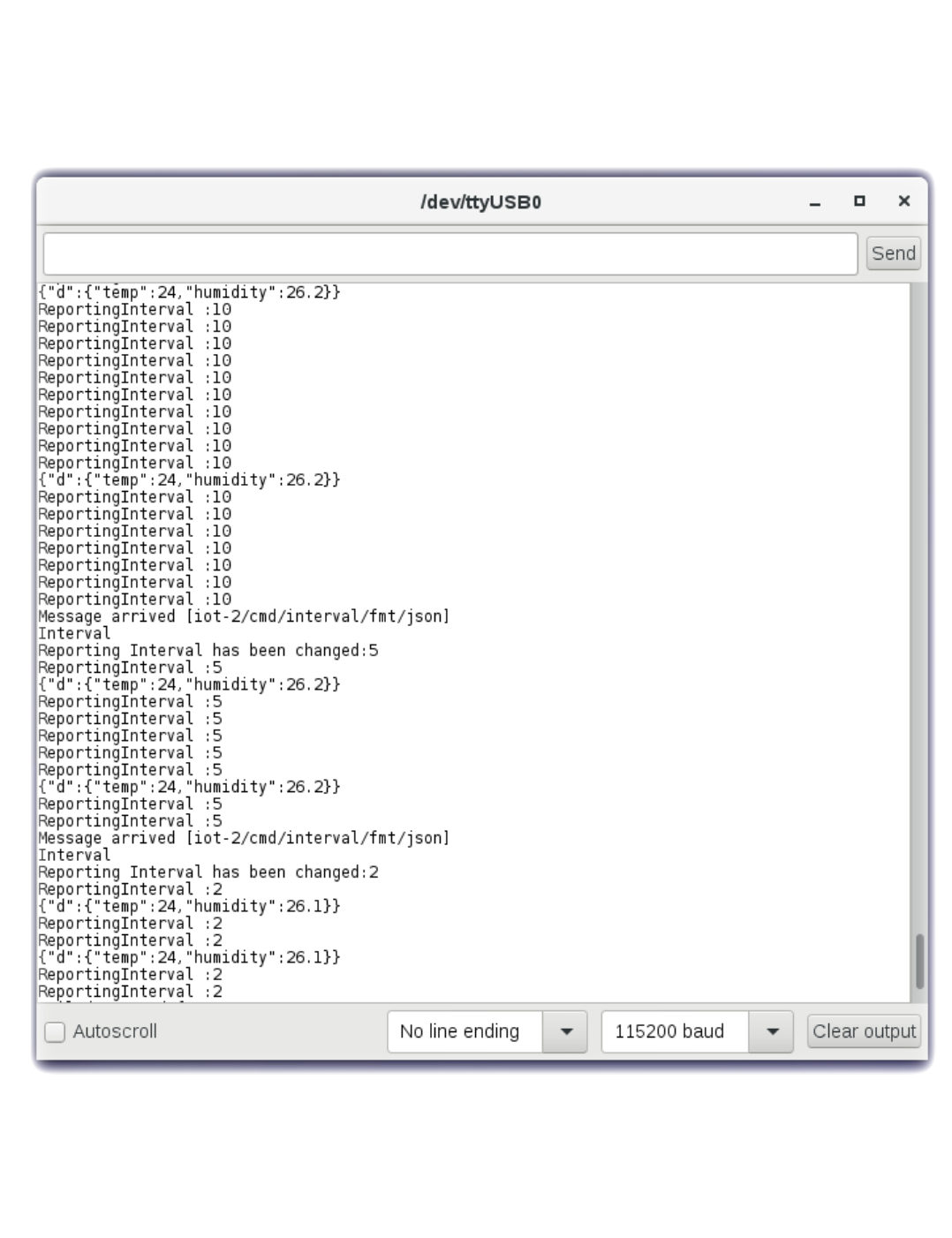
Step 7 - Arduino Serial Monitor
Launch the Serial Monitor from the Arduino IDE - Tools -> Serial Monitor
Watch the Reporting Interval loop
Change the reporting frequency in the Node-RED Dashboard Form.
In this screenshot the Reporting Interval was changed from 10 to 5 to 2 and the frequency that the environmental data was sent increased.
•
•
•
•
4.7.2 Introduction
- 95/145 -
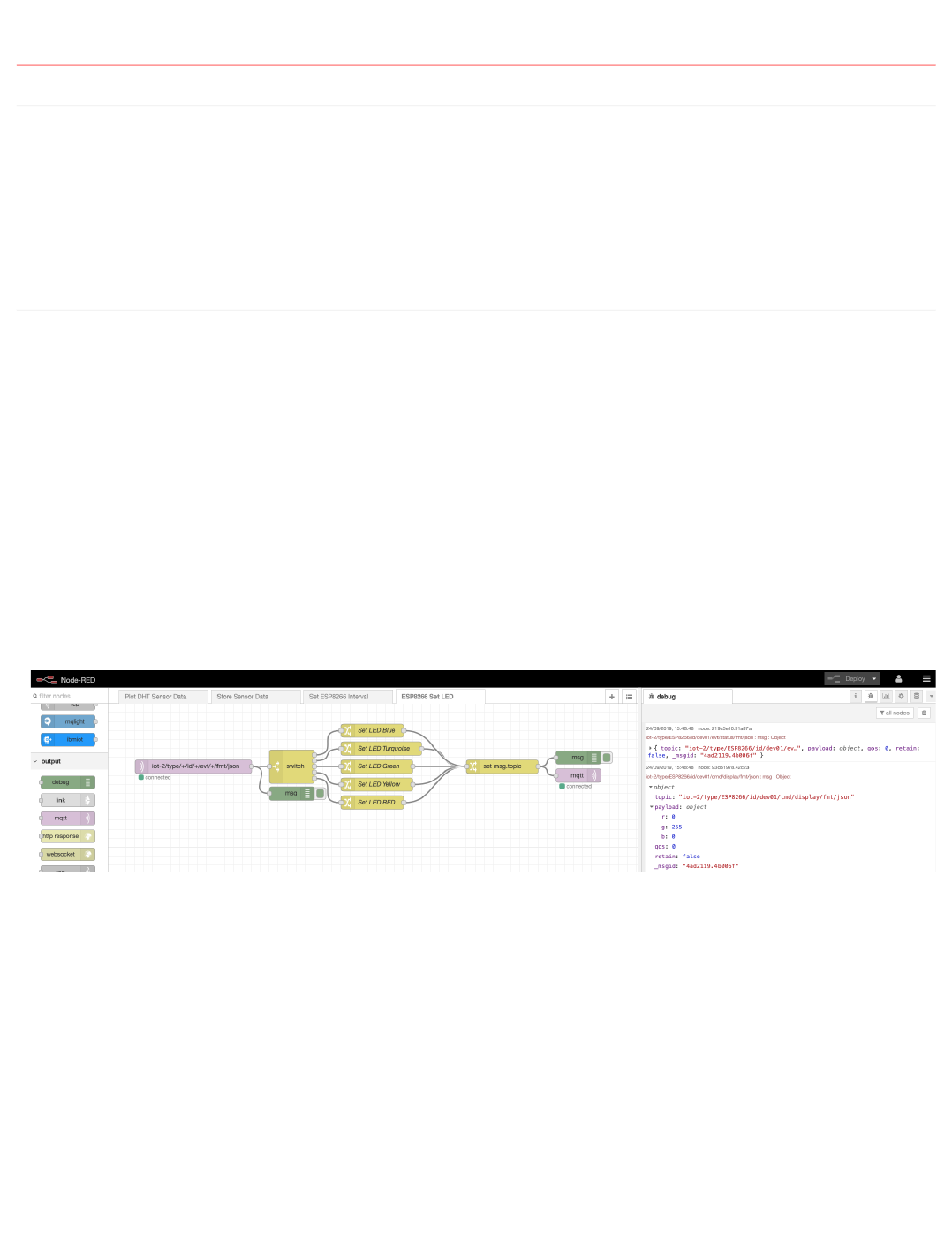
4.8 Control your Device LED Colors via Node-RED
4.8.1 Lab Objectives
In this lab you will modify / control your Device program to receive MQTT commands from the IBM Cloud and build a Node-RED flow to dynamically change
the LED color of the device depending on Alert thresholds. You will learn:
How to send MQTT commands from the IBM Cloud to your device
How to receive MQTT commands within your device program / sketch
How to work with JSON data on the device
4.8.2 Introduction
Remote management and control of IoT Devices is critical to managing the flow of sensor data to the Cloud. Hard coded values in the IoT Device should be
replaced by dynamically controlled logic in the Cloud.
This section will build a Node-RED flow where you can change the LED color and temperature thresholds. A MQTT command will be published from the IBM
Cloud to the device. The device will receive the display update and set the LED color.
Step 1 - Import the Node-RED Dashboard Reporting Interval Form Flow
Open the “Get the Code” github URL listed below, mark or Ctrl-A to select all of the text, and copy the text for the flow to your Clipboard. Recall from a
previous section, click on the Node-RED Menu, then Import, then Clipboard. Paste the text of the flow into the Import nodes dialog and press the red Import
button.
Node-RED Set LED Threshold Flow : Get the Code
Fix the mqtt in and mqtt out node configuration
Click the Deploy button on the top of menu bar to deploy the Node-RED flow.
•
•
•
•
•
•
4.8 Control your Device LED Colors via Node-RED
- 96/145 -
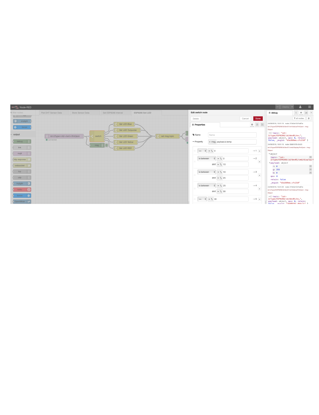
Step 2 - Node-RED Set LED flow
The Node-RED flow receives the DHT environmental sensor data from the mqtt in node.
A Switch node checks the temperature and depending on the value, chooses the Threshold color.
Several Change nodes set the RGB color values.
A Change node sets the topic value. This is generated from the incoming topic using JSONata
The RGB values are sent using a MQTT display device command to the device.
Step 3 - Temperature Threshold
Double-click on the Switch node. An Edit switch node sidebar will open.
The Switch node checks the temperature and depending on the value, chooses the Threshold color.
Press the Cancel button when you have finished reviewing the switch node.
Step 4 - Send MQTT Commands using mqtt out Node
•
•
•
•
•
•
•
•
4.8.2 Introduction
- 97/145 -
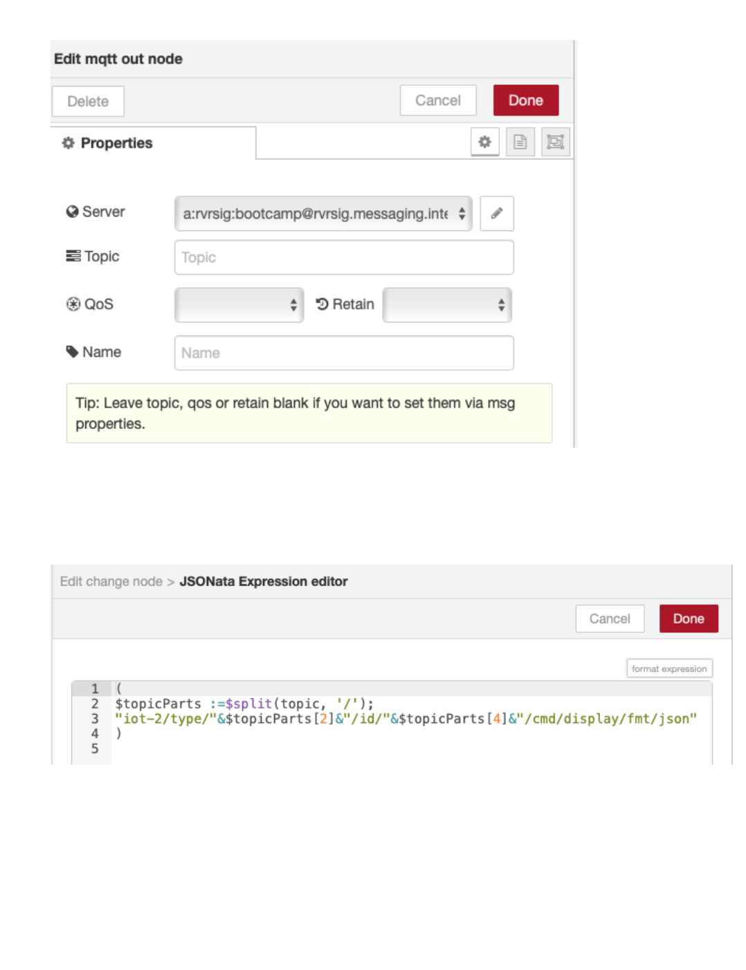
Double-click on the mqtt out node. An Edit mqtt out node sidebar will open.
The mqtt out node has no topic configured as it is sent in with the incoming message.
Press the red Done button to close the mqtt out sidebar.
Double-click the set msg.topic change node to open the Edit change node sidebar
click the ... after the to input box to open the JSONata editor
See how the topic is created by extracting the device type and device id from the incoming topic
The Command Type will be named display.
Press the red Done button and then the red Done button again to close the side bars.
Step 5 - Inspect ESP8266 program which handles Display Device Commands
Return to the Arduino IDE
The prior section already deployed the updated program to your ESP8266 and included the code to handle display commands to set the RGB LED colors.
Inspect the section of code that sets the LED colors.
•
•
•
•
•
•
•
•
•
•
•
4.8.2 Introduction
- 98/145 -

5. Part 4
5.1 Part 4
5.1.1 Introduction to Watson Studio
This section shows you how to deploy the Watson Studio service and how to create your first Jupyter Notebook.
Estimated duration: 20 min
practical Watson Studio
5.1.2 Create training data
This section shows you how to create the training data needed to create a model so you will be able to determine what is happening from the sensor data.
Estimated duration: 20 min
practical Training Data
5.1.3 Jupyter Notebook Analytics - Create model
This section shows you how to use the training data to create a model that can then be used to classify actions.
Estimated duration: 20 min
practical Jupyter Notebook - ESP8266
5.1.4 Run the model on the ESP8266 device
This section takes the output from the Jupyter Notebook and implements the trained model on the ESP8266 device.
Estimated duration: 20 min
practical Implement model on ESP8266
5.1.5 Workshop summary
This section summarises what the workshop covered and also provides some useful links for further exploration of IoT and Data Science
Estimated duration: 10 min
Summary and links
This part of the workshop can be completed without a real device using the Watson IoT Platform device simulator. Instructions on how to use the simulator are included in
this project
here
Note
•
•
•
•
•
•
•
•
•
•
5. Part 4
- 99/145 -

5.2 Watson Studio Set up and Configuration in IBM Cloud
5.2.1 Lab Objectives
In this lab you will set up Watson Studio with a new Project. You will learn:
Watson Studio
How to set up a new Watson Studio Project
How to create a Jupyter Notebook
Introduction
Watson Studio accelerates the machine and deep learning workflows required to infuse AI into your business to drive innovation. It provides a suite of tools for
data scientists, application developers and subject matter experts, allowing them to collaboratively connect to data, wrangle that data and use it to build, train
and deploy models at scale. Successful AI projects require a combination of algorithms + data + team, and a very powerful compute infrastructure.
Learn more from the Experts - Introducing IBM Watson Studio
Step 1 - Watson Studio Setup
Watson Studio needs a data store to enable it to work and it uses the Cloud Object Storage service, so you need an instance of that service available. On a lite
account you can only have a single instance of this service deployed, so if you already have an Object Storage service deployed then you will need to use that,
otherwise you can deploy one when you create your notebook.
•
•
•
•
5.2 Watson Studio Set up and Configuration in IBM Cloud
- 100/145 -
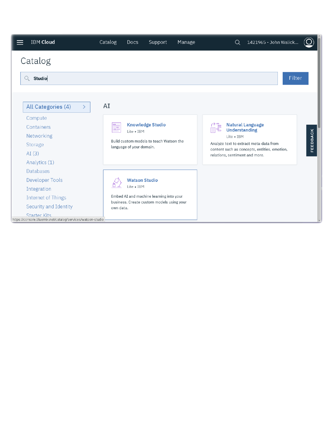

Click on the Create button
After the Watson Studio service is created, click on Get Started
Optionally, walk through the introductory tutorial to learn about Watson Studio
•
•
•
5.2.1 Lab Objectives
- 102/145 -
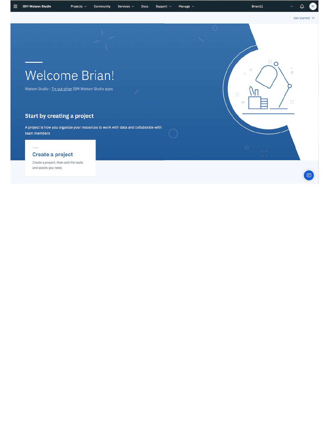
Step 2 - Create a New Project
Projects are your workspace to organize your resources, such as assets like data, collaborators, and analytic tools like notebooks and models
5.2.1 Lab Objectives
- 103/145 -
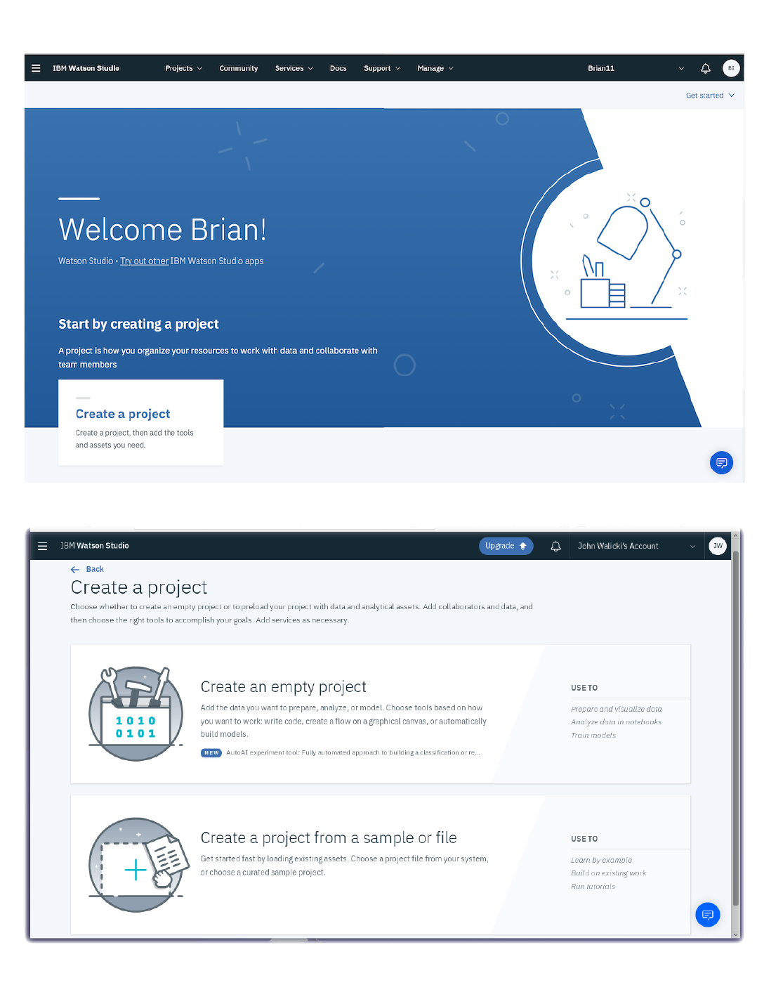
CREATE A NEW PROJECT
Click on Create a project
Select the Create an empty project tile
•
•
5.2.1 Lab Objectives
- 104/145 -
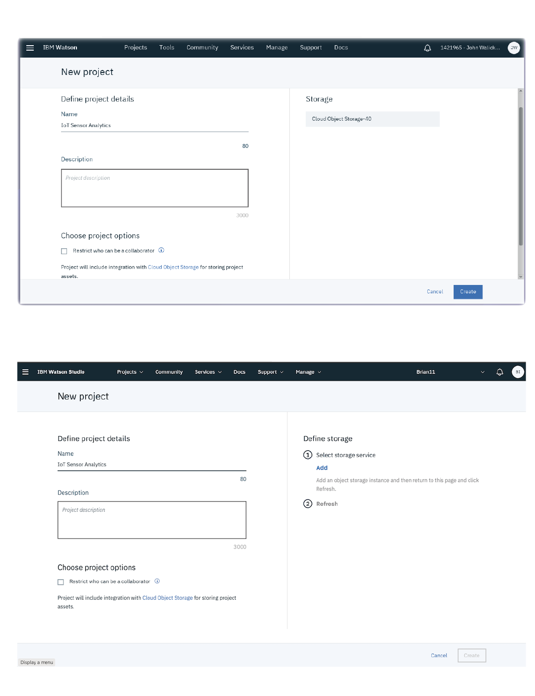
Give your Project a name : IoT Sensor Analytics
If you already have a Cloud Object Storage instance then it should be selected
if you don't have a Cloud Object Storage instance, then press the Add button to create one. Ensure the Lite plan is selected then select Create then
Confirm to create the instance. Press the Refresh button to get the Cloud Storage instance to show up as the selected storage for your new Watson Studio
project.
Press the Create button to create the New Watson Studio project
•
•
•
•
5.2.1 Lab Objectives
- 105/145 -
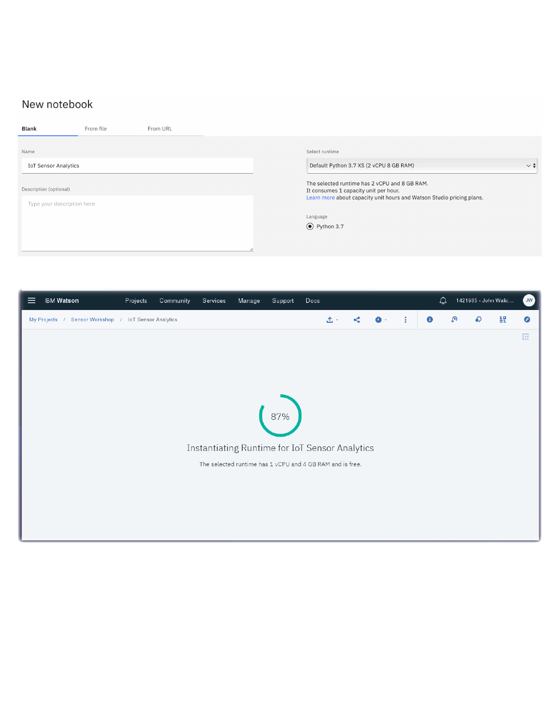
Step 3 - Create a Notebook
From the top menu, select Add to project, and then Notebook
Select Blank
Give the notebook a name : IoT Sensor Analytics
Scroll down to the Select runtime dropdown and choose the default Python 3.7 runtime
Click on Create Notebook
You are now ready to create the training data we will use, so proceed to the next Training Data section.
•
•
•
•
•
5.2.1 Lab Objectives
- 106/145 -

5.2.2 Lab Objectives
In this section we will create the training data needed to train a model. You will learn:
How to format data into an appropriate format for training
How to capture the data required to create the data model
How to reset the database if invalid data has been captured
5.3 Create training data
To train the model we need to identify 2 different situations:
the DHT sensor is not being held
the DHT sensor is being held in a closed hand
It is important to ensure the training data is of good quality, so we are going to create a new database to hold the training database and carefully manage what
data is added to the training database.
The database we need to create needs to have the following contents:
index. This is a unique index for each record. We can use a timestamp for this field
class. This is an indication of which training class this data point represents. 0 for not held and 1 for held
temperature. The temperature value
humidity. The humidity value
To get the data into the database we will create a Node-RED flow, but will only connect up the database when we want data to be recorded.
•
•
•
•
•
•
•
•
•
5.2.2 Lab Objectives
- 107/145 -

5.3.1 Node-RED flow to create the training data
To create the flow, open up the Node-RED editor running on the IBM Cloud (as used in part 3 of this workshop).
5.3.1 Node-RED flow to create the training data
- 108/145 -
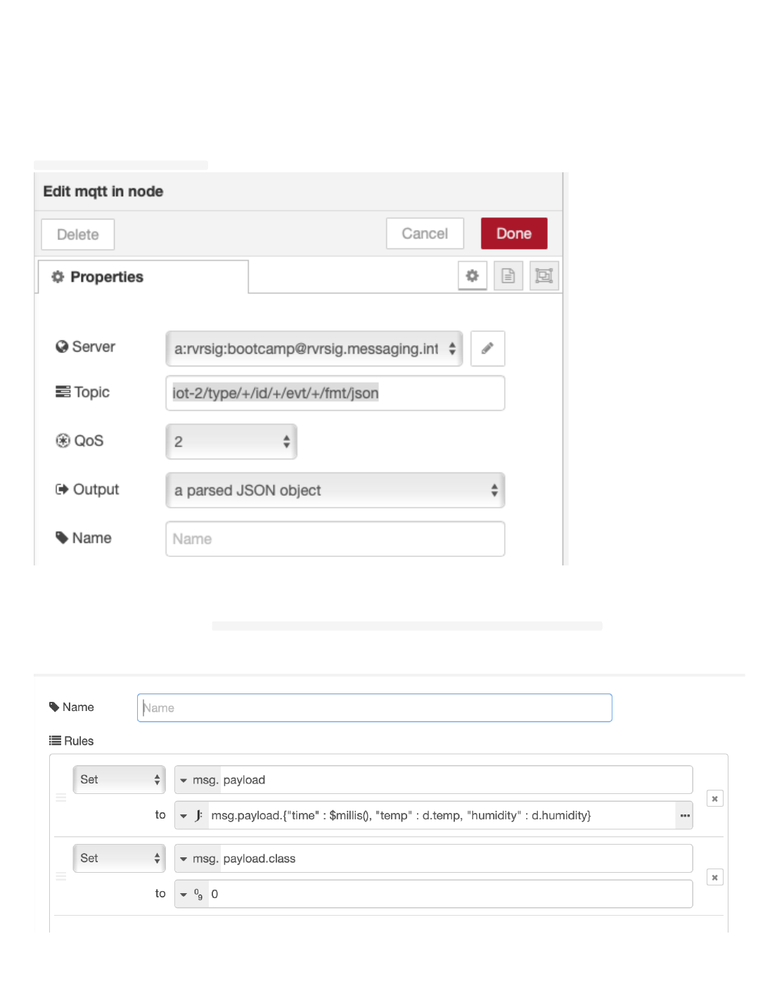
Create a new tab in the editor then add the following nodes:
mqtt in node from the input section of the palette
change node from the function section of the palette
debug node from the output section of the palette
cloudant out node from the storage section of the palette
Connect the mqtt in node to the change node and then the change node to the debug node. DO NOT connect the cloudant out node yet.
Configure the mqtt in node to use the previously defined server configuration and set the topic to listen to all JSON data from all devices
iot-2/type/+/id/+/evt/+/fmt/json as shown:
Configure the change node to have 2 set rules. The first rule reformats the data received from the IoT platform, to flatten it and add a timestamp. The second
rule adds the class property and initially sets it to class 0:
set msg.payload to JSONata expression msg.payload.{"time" : $millis(),"temp" : d.temp, "humidity" : d.humidity}
set msg.payload.class to number 0
as shown :
1.
2.
3.
4.
5.
6.
7.
8.
9.
10.
5.3.1 Node-RED flow to create the training data
- 109/145 -
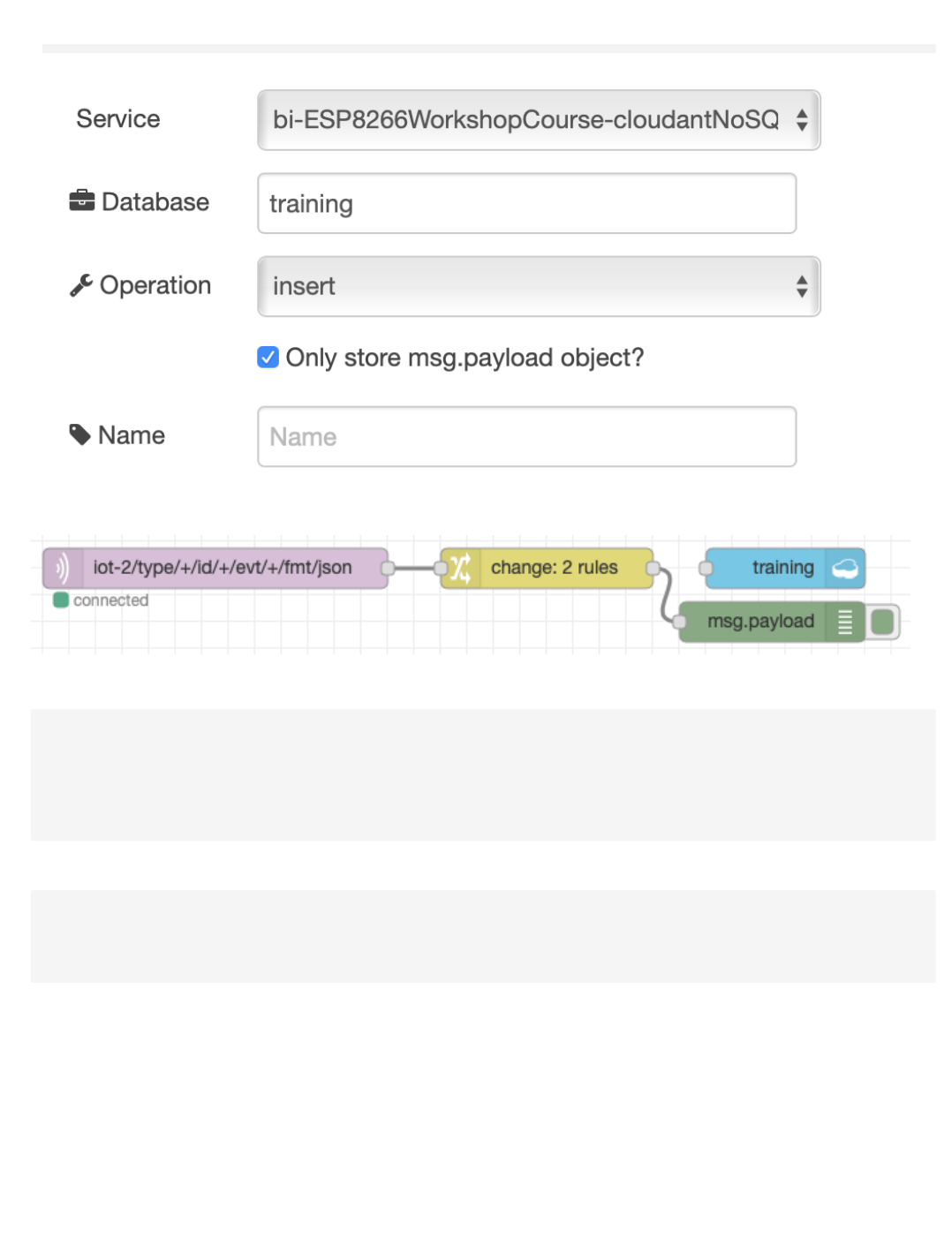
Configure the cloudant out node to use the cloud service and set the database name to training and ensure the operation is set to insert and to only store
msg.payload object as shown:
You should have a flow that looks like this:
If your flow is not working then you can import the sample flow, which is also available in the flows folder in part4 of the repo :
This flow creates the following output, which we will write to the database:
11.
[{
"id"
:
"332d48ae.1555b"
,
"type"
:
"change"
,
"z"
:
"46c77ae0.25061c"
,
"name"
:
""
,
"rules"
:[{
"t"
:
"set"
,
"p"
:
"payload"
,
"pt"
:
"msg"
,
"to"
:
"msg.payload.{\"time\" : $millis(),
\"temp\" : d.temp, \"humidity\" : d.humidity} "
,
"tot"
:
"jsonata"
},
{
"t"
:
"set"
,
"p"
:
"payload.class"
,
"pt"
:
"msg"
,
"to"
:
"0"
,
"tot"
:
"num"
}],
"action"
:
""
,
"property"
:
""
,
"from"
:
""
,
"to"
:
""
,
"reg"
:
false
,
"x"
:
1040
,
"y"
:
260
,
"wires"
:
[[
"c5369a33.c87e08"
]]},
{
"id"
:
"c5369a33.c87e08"
,
"type"
:
"debug"
,
"z"
:
"46c77ae0.25061c"
,
"name"
:
""
,
"active"
:
true
,
"tosidebar"
:
true
,
"console"
:
false
,
"tostatus"
:
false
,
"complete"
:
"false"
,
"x"
:
1210
,
"y"
:
300
,
"wires"
:[]},{
"id"
:
"95115355.458a9"
,
"type"
:
"cloudant
out"
,
"z"
:
"46c77ae0.25061c"
,
"name"
:
""
,
"cloudant"
:
""
,
"database"
:
"training"
,
"service"
:
""
,
"payonly"
:
true
,
"operation"
:
"insert"
,
"x"
:
1220
,
"y"
:
260
,
"wires"
:[]},
{
"id"
:
"b1eeaccd.78ca6"
,
"type"
:
"mqtt in"
,
"z"
:
"46c77ae0.25061c"
,
"name"
:
""
,
"topic"
:
"iot-2/type/+/id/+/evt/+/fmt/json"
,
"qos"
:
"2"
,
"datatype"
:
"json"
,
"broker"
:
""
,
"x"
:
790
,
"y"
:
260
,
"wires"
:[[
"332d48ae.1555b"
]]}]
{
"time"
:
1546969694969
,
"temp"
:
20
,
"humidity"
:
51
,
"class"
:
0
}
5.3.1 Node-RED flow to create the training data
- 110/145 -
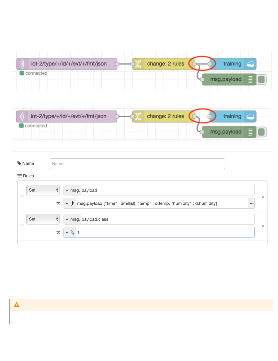
5.3.2 Creating the training data
To create the training data you may want to use the interval dashboard to set the interval to something like 5 seconds, to reduce the time needed to gather the
required data. We are aiming to have a similar number of data points for each class in the training data.
Ensure the ESP8266 is working and you can see the debug output as shown above.
As we want to record class 0 data, leave the DHT sensor alone and wait 30 seconds to ensure the data is stable. Then connect up the cloudant out node and
deploy the flow:
Wait until about 20-30 records have been written then delete the connection to the cloudant out node and deploy the flow to stop any more records being
written:
Edit the change node configuration to set the class to 1 :
Hold the DHT sensor in your hand, ensuring you don't dislodge any of the connecting cables. Wait a while to let the readings settle down
Connect the change node to the cloudant out node and deploy the flow. Ensure you remain holding onto the DHT sensor
Wait until about 20-30 records have been written (try to get the same number of database records as you created for class 0) then delete the connection to the
cloudant out node and deploy to stop recording any more data. You can release the DHT sensor now
5.3.3 Reset the training database
1.
2.
3.
4.
5.
6.
7.
Only complete the following section if you have invalid data in your training database, as it will clear out all the captured training data
Warning
5.3.2 Creating the training data
- 111/145 -

It is important that you have clean training data, so if you need to restart recording the training database you can easily delete the database from cloudant:
5.3.3 Reset the training database
- 112/145 -
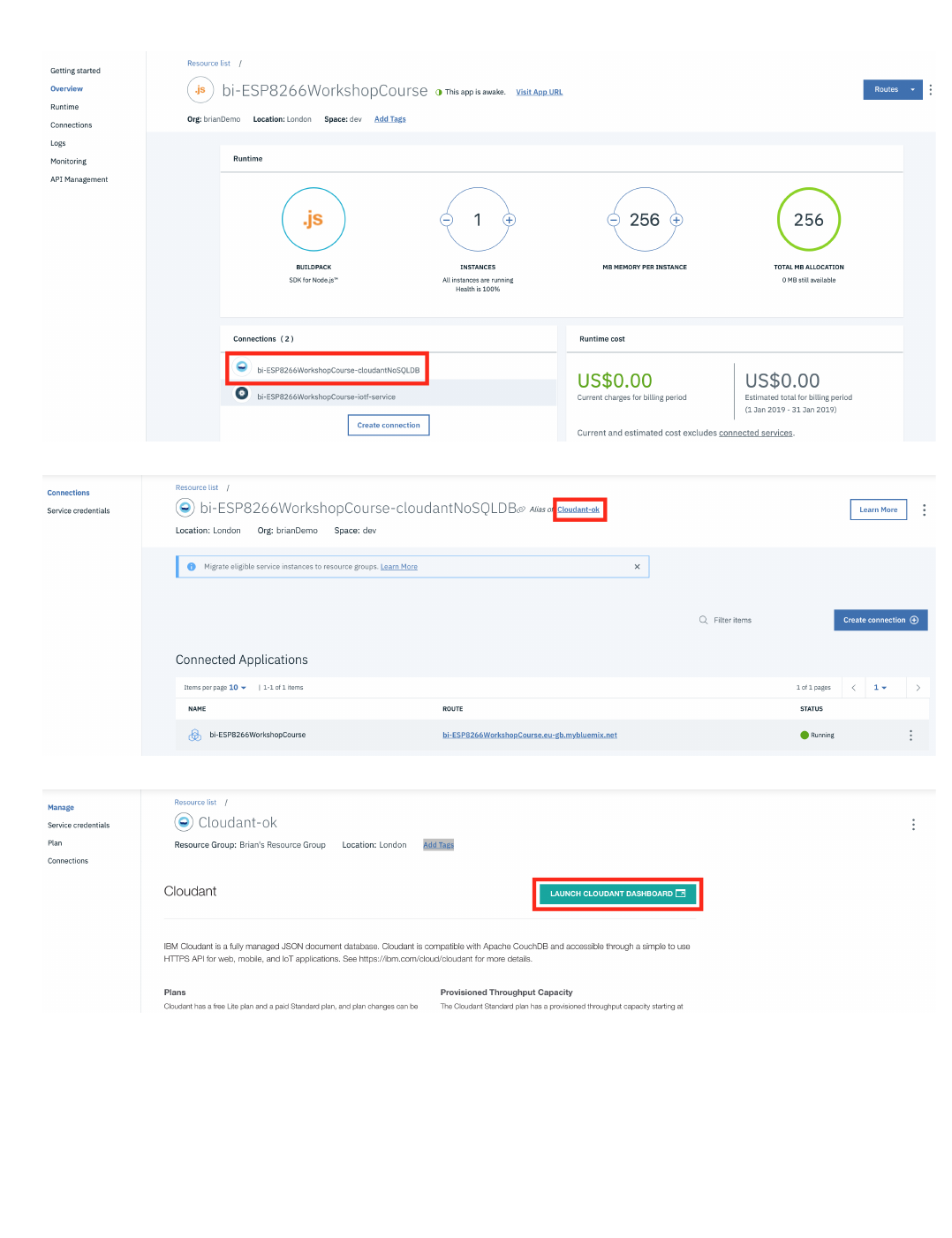
Ensure the connection between the change node and the cloudant out node has been deleted, so no data is being written to the database
From the Application overview page in the IBM Cloud console select the cloudant database from the connections section:
Select the alias link :
Launch the console :
1.
2.
3.
4.
5.3.3 Reset the training database
- 113/145 -
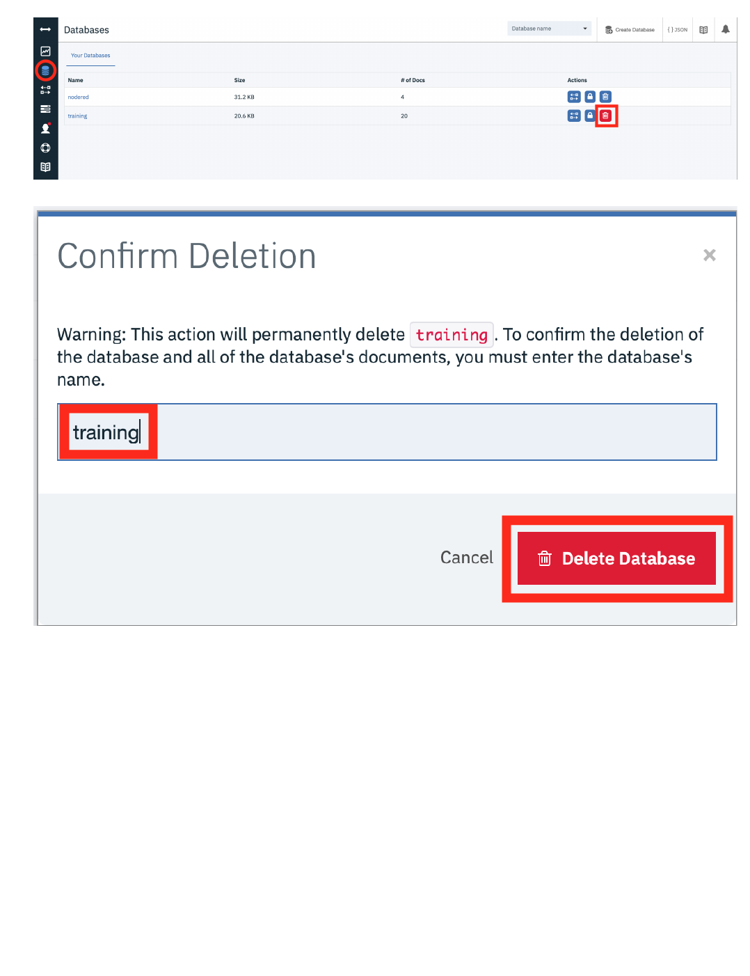
In the databases section select the bin icon next to the training database :
Enter the database name in the text box then press the delete button to delete the database :
You can now start creating the training data again - the database is automatically created when the Node-RED flow is next deployed
Once you have your training data recorded you can move to the next section
5.
6.
5.3.3 Reset the training database
- 114/145 -

5.4 Run a Jupyter Notebook in Watson Studio
5.4.1 Lab Objectives
In this lab you will read IoT data into a Watson Studio Project Jupyter Notebook and perform some analytics. You will learn:
How to use Jupyter Notebooks
How to read data from a Cloudant DB into Spark
How to manipulate the data within the notebook environment
How to create a model to be able to classify the IoT data to determine what is happening.
5.4.2 Introduction
Jupyter Notebooks are a web-based computational environment for interactive data science and scientific computing. A Jupyter Notebook document is a JSON
document, following a versioned schema, and containing an ordered list of input/output cells which can contain code, text (using Markdown), mathematics, plots
and rich media, usually ending with the ".ipynb" extension. A Jupyter kernel is a program responsible for handling various types of request (code execution, code
completions, inspection), and providing a reply.
The steps below will build up the Jupyter notebook, there is a solution notebook at the end to use if you need assistance to complete any step.
There are a number of ways of getting data into a Jupyter notebook. The User interface provides a way to upload files and create connections to data providerts.
For this example we will connect to the Cloudant data where the training data was stored using a Cloudant python library.
•
•
•
•
5.4 Run a Jupyter Notebook in Watson Studio
- 115/145 -

5.4.3 Step 1 - Cloudant Credentials
Before we can read the ESP8266 IoT temperature and humidity data into a Jupyter notebook we need to create credentials for the Cloudant database where the
training data is stored.
5.4.3 Step 1 - Cloudant Credentials
- 116/145 -
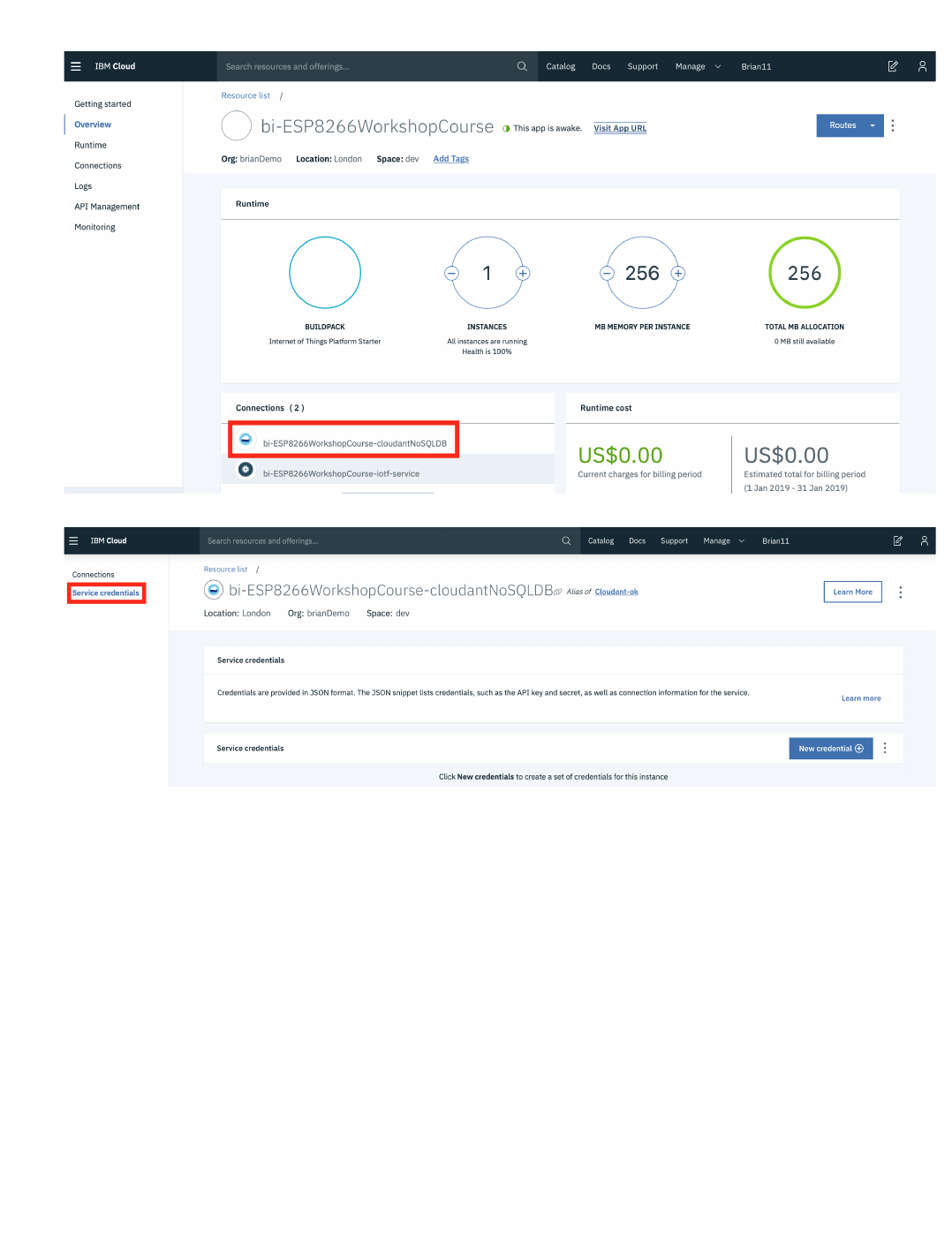
Open a new browser tab.
Return to the IBM Cloud dashboard and your IoT Starter application. Click on the cloudantNoSQLDB service connection (1).
Read about the Cloudant Storage service and click on the Service credentials menu item in the left menu bar.
•
•
•
5.4.3 Step 1 - Cloudant Credentials
- 117/145 -
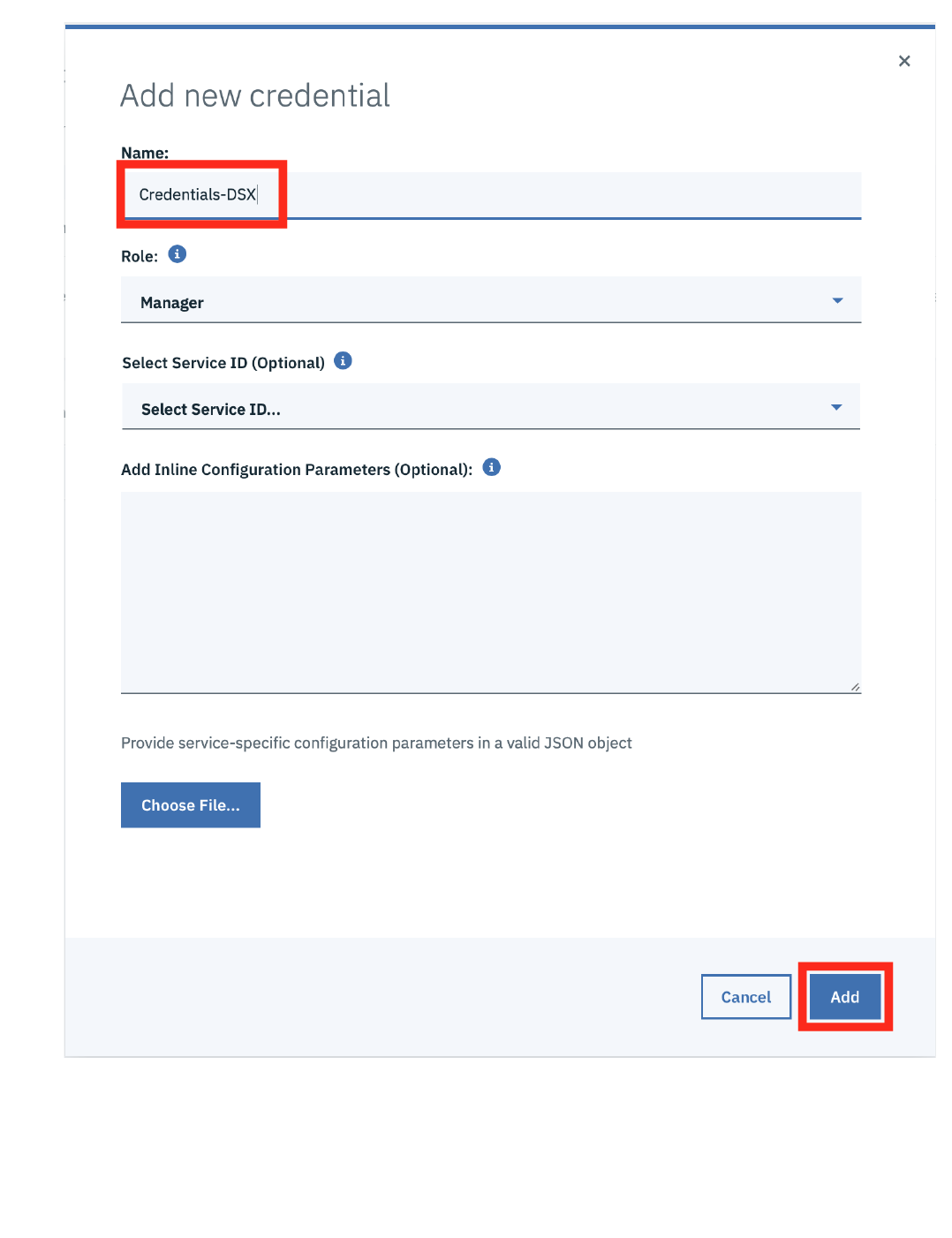
Click on New credential
Give your credential a name: Credentials-DSX
Click on Add
Expand the View credentials twistie
The Cloudant hostname, user and password credentials will be displayed.
Keep this browser tab open or copy the credentials to your text editor, as you will use these credentials in the next Step.
•
•
•
•
•
•
5.4.3 Step 1 - Cloudant Credentials
- 118/145 -
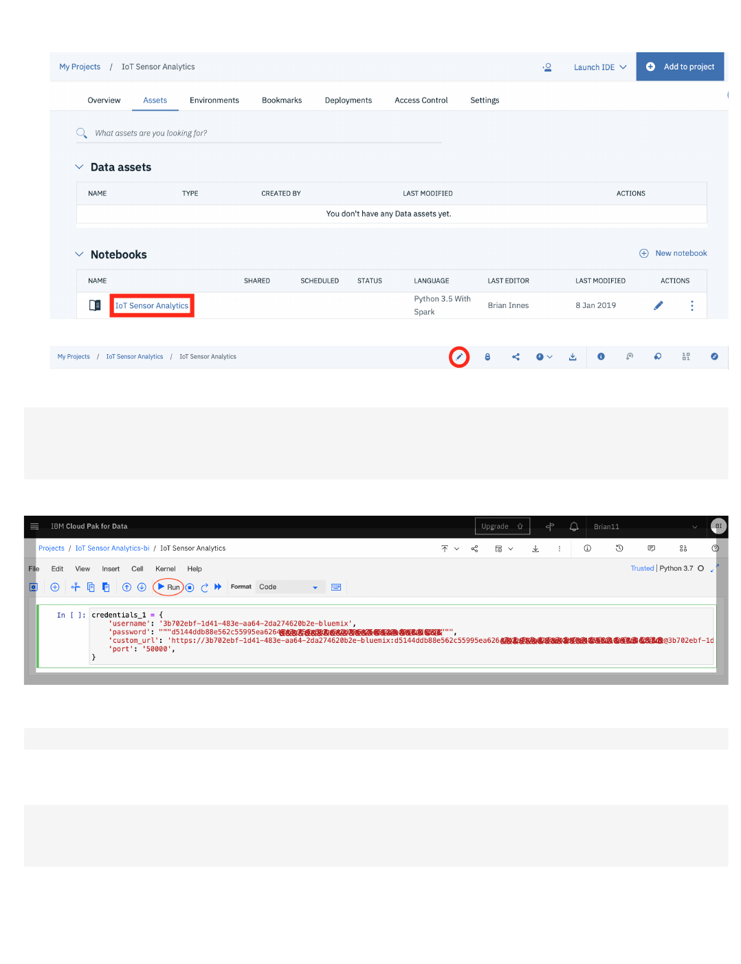
Step 2 - Loading Cloudant data into the Jupyter notebook
Return to the Watson Studio browser tab and open the IoT Sensor Analytics notebook.
Make certain you are in Edit mode by clicking on the Pencil icon if it is showing.
Copy the following code into the first cell in the notebook, replacing \, \ and \ with values obtained in the previous step
- Once you have updated the credentials and URL then you can run the cell by pressing the Run button. This will execute the code in the cell and create a new cell.
in the next cell add code to import the cloudant package and run the cell
The next cell will create the connection to Cloudant, so enter the code and run the cell. Note this uses the credential information created in the first cell.
This shows that data is retained within the Jupyter environment, so you can access variables created in previous cells.
then open the training database and get the number of documents available in the database. When you run this cell you should see the number of
documents in the training database output below the cell
•
•
•
credentials_1
=
{
'username'
:
'<Cloudant Username>'
,
'password'
:
"""<Cloudant Password>"""
,
'custom_url'
:
'<Cloudant URL>'
,
'port'
:
'50000'
,
}
•
!
pip
install
cloudant
•
from
cloudant
import
Cloudant
u
=
credentials_1
[
'username'
]
p
=
credentials_1
[
'password'
]
a
=
credentials_1
[
'username'
]
client
=
Cloudant
(
u
,
p
,
account
=
a
,
connect
=
True
,
auto_renew
=
True
)
•
5.4.3 Step 1 - Cloudant Credentials
- 119/145 -
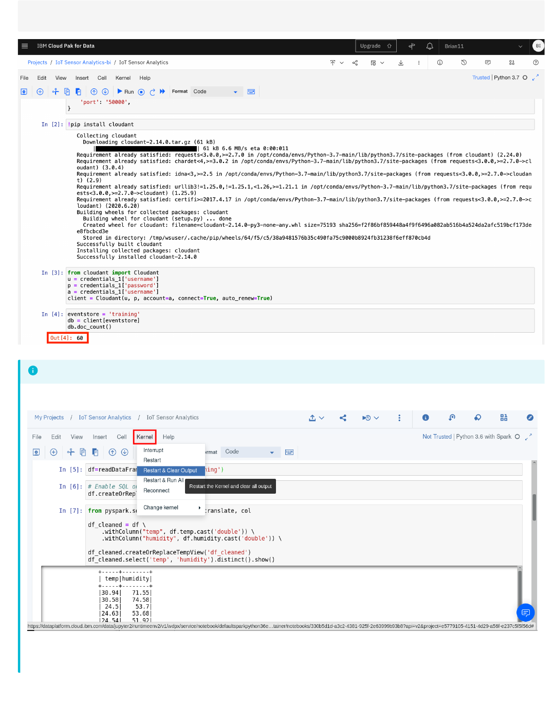
eventstore
=
'training'
db
=
client
[
eventstore
]
db
.
doc_count
()
If you want to clear out the data created by previously run steps then you can use the
Kernel
menu option to clear out and restart the notebook, or clear out and run all steps:
If you clear output then you can select the first cell and press run, which will run the cell then move to the next cell in the notebook. Keep pressing run to run each cell in
turn, ensure you wait for each cell to complete (At the left side of the cell the indicator
[*]
turns to
[n]
, where n is a number) before running the next step.
Info
5.4.3 Step 1 - Cloudant Credentials
- 120/145 -

5.4.4 Step 3 - Work with the training data
Within the notebook you are able to manipulate the data. You usually need to examine the training data and maybe clean it up before creating the model.
Read a subset of the records available -- if the event store holds many thousands of entries, there may be insufficient memory available to load them all
The include_docs=True is necessary, otherwise all that is returned is the list of document ids.
Look at the first event/observation document, and select the features within the "doc" key that you want to include in modelling
In this case, the features of interest are temperature,humidity - the timestamp ts is going to be useful for spotting trends, time-based anomalies etc. The
class property provides the expected classification given the temperature and humidity readings, which will be used to train the model.
Iterate the returned documents into an array of events with common schema
The events are now loaded in a form that can be converted into a dataframe, which will be used for subsequent steps
Let's take a look as some of the features over time. We'll use MatPlotLib for visualisation
visualise temperature over time
visualise humidity over time
5.4.5 Step 4 - Creating the binary classifier model
Once you are confident you have the correct training data available you can proceed to creating the model.
we will use the popular scikit-learn and pandas packages to build the model
separate the sensor readings from the classification (class)
build a dataframe containing the training data and display the data frames
•
•
loadlimit
=
1000
alldocs
=
db
.
all_docs
(
limit
=
loadlimit
,
include_docs
=
True
)
len
(
alldocs
[
'rows'
])
•
alldocs
[
'rows'
][
0
]
•
•
events
=
[]
for
r
in
alldocs
[
'rows'
]:
doc
=
r
[
"doc"
]
obs
=
[
doc
[
'time'
],
doc
[
'temp'
],
doc
[
'humidity'
],
doc
[
'class'
]]
events
.
append
(
obs
)
•
import
pandas
as
pd
df
=
pd
.
DataFrame
(
data
=
events
,
columns
=
[
"timestamp"
,
"temperature"
,
"humidity"
,
"class"
])
display
(
df
)
•
import
matplotlib.pyplot
as
plt
•
plt
.
scatter
(
df
[
'timestamp'
],
df
[
'temperature'
])
•
plt
.
scatter
(
df
[
'timestamp'
],
df
[
'humidity'
])
•
from
sklearn
import
linear_model
import
random
from
scipy.special
import
expit
•
aX
=
[]
aY
=
[]
for
i
,
row
in
df
.
iterrows
():
t
=
row
[
"temperature"
]
h
=
row
[
"humidity"
]
c
=
row
[
"class"
]
obs
=
[
t
,
h
]
aX
.
append
(
obs
)
aY
.
append
([
c
])
•
5.4.4 Step 3 - Work with the training data
- 121/145 -
First we split the training data into 2 groups of 2 subsets. 75% of the data will be used to train the model and 25% will be used to test the model
look at the data to be used to train the model
Use the default Logistic Regression function to train based on the input observations
5.4.6 Step 5 - Test the model
Once you have built the model you will want to verify how accurate the model is, so there are a number of ways we can do this. The first one is to use an
evaluator to get a measure of how good the model is. A value of 1.0 represents 100% accuracy over the training data.
calculate the classification from the model for the 25% of the training data that was set aside to test the model
Run a comparison between the actual values for the class, and the calculated values - this will generate a "confusion matrix" which shows how well the
model can predict classes, and when it gets it wrong (false positives, false negatives)
output the model scores. 1.0 is 100% accurate
you can access the help for the logistic regression function
Output the parameters of the trained model, so you can implement it on the ESP8266. Initially the coefficients. As the temperature was the first column in
the training data, the first coefficient is the temperature coefficient and the second value is the humidity
Output the intercept value
import
pandas
as
pd
X
=
pd
.
DataFrame
(
data
=
aX
,
columns
=
[
"temperature"
,
"humidity"
])
y
=
pd
.
DataFrame
(
data
=
aY
,
columns
=
[
"class"
])
display
(
y
)
display
(
X
)
•
# split X and y into training and testing sets
from
sklearn.model_selection
import
train_test_split
#fraction of input data to hold for testing -- excluded from the training
testsplit
=
0.25
X_train
,
X_test
,
y_train
,
y_test
=
train_test_split
(
X
,
y
,
test_size
=
testsplit
,
random_state
=
0
)
•
X_train
•
from
sklearn.linear_model
import
LogisticRegression
# instantiate the model (using the default parameters)
logreg
=
LogisticRegression
()
# fit the model with data
logreg
.
fit
(
X_train
,
y_train
)
You can ignore the warning generated by the above cell
Info
•
# generate the predictions from the test subset
y_pred
=
logreg
.
predict
(
X_test
)
•
from
sklearn
import
metrics
cnf_matrix
=
metrics
.
confusion_matrix
(
y_test
,
y_pred
)
cnf_matrix
•
print
(
"Accuracy:"
,
metrics
.
accuracy_score
(
y_test
,
y_pred
))
print
(
"Precision:"
,
metrics
.
precision_score
(
y_test
,
y_pred
))
print
(
"Recall:"
,
metrics
.
recall_score
(
y_test
,
y_pred
))
•
help
(
logreg
)
•
logreg
.
coef_
•
5.4.6 Step 5 - Test the model
- 122/145 -
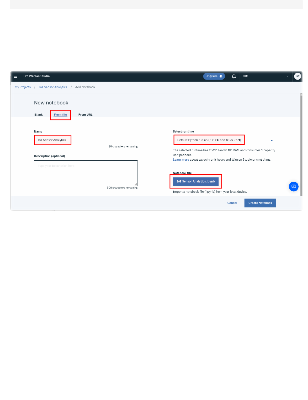
These values will be used in the next section to implement the trained model on the ESP8266.
5.4.7 Sample solution
There is a sample solution for this part provided in the notebooks folder. If you have an issue and want to see the solution then within the IoT Sensor Analytics
project select to add a new notebook. Select to create a notebook from file and give the notebook a name - here IoT Sensor Analytics - solution has been used.
This assumes you have the file locally on your machine. Select choose file and locate the IoT Sensor Analytics.ipynb file. Finally ensure you have the Default
Python 3.7 XS runtime selected then press Create Notebook
Alternatively, you can select to import from URL and set the URL to : https://raw.githubusercontent.com/binnes/esp8266Workshop/master/docs/part4/notebooks/
IoT%20Sensor%20Analytics.ipynb
logreg
.
intercept_
5.4.7 Sample solution
- 123/145 -

5.5 Run the model on the ESP8266 device
5.5.1 Learning Objectives
In this section you will learn how to take the model parameters generated in the previous section and implement a function to run the model on the ESP8266 to
provide real-time classification.
5.5.2 Logistic regression
The algorithm at the heart of the model we generated is Logistic Regression, which uses the Logit function (long-odds) then applies the Logistic sigmoid function:
Logit function for 2 predictor values h and t (humidity and temp) is: C + w1*h + w2*t where C is a constant and w1 and w2 are weighting values for the
predictors.
The values of C, w1 and w2 are the values from the Jupyter Notebook in the previous section:
Here the coefficients are w1 and w2 and the intercept is the constant C. Note the order of the weightings was specified by the order of the properties fed into the
Vector Assembler:
so the first coefficient is the weighting for the humidity property and the second coefficient is the weighting for the temperature property.
The sigmoid function is: f(x) = 1/(1+e^-x)
Given the two functions we can create an implementation in C that can be integrated with our ESP8266 application:
5.5.3 Incorporating real-time classification on the ESP8266
Now we have a function that applies the trained model that can be implemented in C on the ESP8266, we can incorporate the result into our code.
vectorAssembler
=
VectorAssembler
(
inputCols
=
[
"humidity"
,
"temp"
],
outputCol
=
"features"
)
#include
<math.h>
#define MODEL_INTERCEPT -14.172253183961212
#define MODEL_TEMP_COEF -3.0625
#define MODEL_HUM_COEF 1.3247
float
applyModel
(
float
h
,
float
t
)
{
// apply logit formula C + w1*h + w2*t
float
regression
=
MODEL_INTERCEPT
+
MODEL_HUM_COEF
*
h
+
MODEL_TEMP_COEF
*
t
;
// return sigmoid logistic function on logit result
return
1
/
(
1
+
exp
(
0.0
-
(
double
)
regression
));
}
5.5 Run the model on the ESP8266 device
- 124/145 -

Each time new readings are made we can call the
applyModel() function. The output of the function will be a floating point number where numbers nearest 0.0
represent class 0 in our training data and numbers nearest 1.0 represent class 1 in our training scenario. A simple comparison assigning results less than 0.5 to
class 0 and results above 0.5 to class 1 is all that is needed to assign a set of readings to a class.
So we can incorporate this into the loop function to set another property on the message sent to the IoT platform:
The completed ESP8266 application should now look like:
// Apply the model to the sensor readings
float
modelPrediction
=
applyModel
(
h
,
t
);
...
status
[
"class"
]
=
modelPrediction
<
0.5
?
0
:
1
;
#include
<LittleFS.h>
#include
<ESP8266WiFi.h>
#include
<time.h>
#include
<Adafruit_NeoPixel.h>
#include
<DHT.h>
#include
<ArduinoJson.h>
#include
<PubSubClient.h>
#include
<math.h>
// --------------------------------------------------------------------------------------------
// UPDATE CONFIGURATION TO MATCH YOUR ENVIRONMENT
// --------------------------------------------------------------------------------------------
// Watson IoT connection details
#define MQTT_HOST "<orgID>.messaging.internetofthings.ibmcloud.com"
#define MQTT_PORT 8883
#define MQTT_DEVICEID "d:<orgID>:<type>:<id>"
#define MQTT_USER "use-token-auth"
#define MQTT_TOKEN "<token>"
#define MQTT_TOPIC "iot-2/evt/status/fmt/json"
#define MQTT_TOPIC_DISPLAY "iot-2/cmd/display/fmt/json"
#define MQTT_TOPIC_INTERVAL "iot-2/cmd/interval/fmt/json"
#define CA_CERT_FILE "/rootCA_certificate.pem"
#define KEY_FILE "/SecuredDev01_key_nopass.pem"
#define CERT_FILE "/SecuredDev01_crt.pem"
// Add GPIO pins used to connect devices
#define RGB_PIN 5
// GPIO pin the data line of RGB LED is connected to
#define DHT_PIN 4
// GPIO pin the data line of the DHT sensor is connected to
// Specify DHT11 (Blue) or DHT22 (White) sensor
//#define DHTTYPE DHT22
#define DHTTYPE DHT11
#define NEOPIXEL_TYPE NEO_RGB + NEO_KHZ800
// Temperatures to set LED by (assume temp in C)
#define ALARM_COLD 0.0
#define ALARM_HOT 30.0
#define WARN_COLD 10.0
#define WARN_HOT 25.0
//Timezone info
#define TZ_OFFSET -5
//Hours timezone offset to GMT (without daylight saving time)
#define TZ_DST 60
//Minutes timezone offset for Daylight saving
// Add WiFi connection information
char
ssid
[]
=
"<SSID>"
;
// your network SSID (name)
char
pass
[]
=
"<PASSWORD>"
;
// your network password
// Model parameters from part4 - to implement the model on the ESP8266
// Replace these parameters with the model parameters from your Jupyter Notebook
#define MODEL_INTERCEPT -14.172253183961212
#define MODEL_TEMP_COEF -3.0625
#define MODEL_HUM_COEF 1.3247
// --------------------------------------------------------------------------------------------
// SHOULD NOT NEED TO CHANGE ANYTHING BELOW THIS LINE
// --------------------------------------------------------------------------------------------
Adafruit_NeoPixel
pixel
=
Adafruit_NeoPixel
(
1
,
RGB_PIN
,
NEOPIXEL_TYPE
);
DHT
dht
(
DHT_PIN
,
DHTTYPE
);
// MQTT objects
void
callback
(
char
*
topic
,
byte
*
payload
,
unsigned
int
length
);
BearSSL
::
WiFiClientSecure
wifiClient
;
PubSubClient
mqtt
(
MQTT_HOST
,
MQTT_PORT
,
callback
,
wifiClient
);
BearSSL
::
X509List
*
rootCert
;
BearSSL
::
X509List
*
clientCert
;
BearSSL
::
PrivateKey
*
clientKey
;
// variables to hold data
StaticJsonDocument
<
100
>
jsonDoc
;
JsonObject
payload
=
jsonDoc
.
to
<
JsonObject
>
();
JsonObject
status
=
payload
.
createNestedObject
(
"d"
);
5.5.3 Incorporating real-time classification on the ESP8266
- 125/145 -

StaticJsonDocument<100> jsonReceiveDoc;
static char msg[50];
float h = 0.0; // humidity
float t = 0.0; // temperature
unsigned char r = 0; // LED RED value
unsigned char g = 0; // LED Green value
unsigned char b = 0; // LED Blue value
int32_t ReportingInterval = 10; // Reporting Interval seconds
float applyModel(float h, float t) {
// apply regression formula w1 + w2x + w3y
float regression = MODEL_INTERCEPT + MODEL_HUM_COEF * h + MODEL_TEMP_COEF * t;
// return sigmoid logistic function on regression result
return 1/(1 + exp(0.0 - (double)regression));
}
void callback(char* topic, byte* payload, unsigned int length) {
// handle message arrived
Serial.print("Message arrived [");
Serial.print(topic);
Serial.print("] : ");
payload[length] = 0; // ensure valid content is zero terminated so can treat as c-string
Serial.println((char *)payload);
DeserializationError err = deserializeJson(jsonReceiveDoc, (char *)payload);
if (err) {
Serial.print(F("deserializeJson() failed with code "));
Serial.println(err.c_str());
} else {
JsonObject cmdData = jsonReceiveDoc.as<JsonObject>();
if (0 == strcmp(topic, MQTT_TOPIC_DISPLAY)) {
//valid message received
r = cmdData["r"].as<unsigned char>(); // this form allows you specify the type of the data you want from the JSON object
g = cmdData["g"];
b = cmdData["b"];
jsonReceiveDoc.clear();
pixel.setPixelColor(0, r, g, b);
pixel.show();
} else if (0 == strcmp(topic, MQTT_TOPIC_INTERVAL)) {
//valid message received
ReportingInterval = cmdData["Interval"].as<int32_t>(); // this form allows you specify the type of the data you want from the JSON object
Serial.print("Reporting Interval has been changed:");
Serial.println(ReportingInterval);
jsonReceiveDoc.clear();
} else {
Serial.println("Unknown command received");
}
}
}
void setup() {
char *ca_cert = nullptr;
char *client_cert = nullptr;
char *client_key = nullptr;
// Start serial console
Serial.begin(115200);
Serial.setTimeout(2000);
while (!Serial) { }
Serial.println();
Serial.println("ESP8266 Sensor Application");
// Start WiFi connection
WiFi.mode(WIFI_STA);
WiFi.begin(ssid, pass);
while (WiFi.status() != WL_CONNECTED) {
delay(500);
Serial.print(".");
}
Serial.println("");
Serial.println("WiFi Connected");
// Start connected devices
dht.begin();
pixel.begin();
// Get cert(s) from file system
LittleFS.begin();
File ca = LittleFS.open(CA_CERT_FILE, "r");
if(!ca) {
Serial.println("Couldn't load CA cert");
} else {
size_t certSize = ca.size();
ca_cert = (char *)malloc(certSize);
if (certSize != ca.readBytes(ca_cert, certSize)) {
Serial.println("Loading CA cert failed");
} else {
Serial.println("Loaded CA cert");
rootCert = new BearSSL::X509List(ca_cert);
wifiClient.setTrustAnchors(rootCert);
}
5.5.3 Incorporating real-time classification on the ESP8266
- 126/145 -

free(ca_cert);
ca.close();
}
File key = LittleFS.open(KEY_FILE, "r");
if(!key) {
Serial.println("Couldn't load key");
} else {
size_t keySize = key.size();
client_key = (char *)malloc(keySize);
if (keySize != key.readBytes(client_key, keySize)) {
Serial.println("Loading key failed");
} else {
Serial.println("Loaded key");
clientKey = new BearSSL::PrivateKey(client_key);
}
free(client_key);
key.close();
}
File cert = LittleFS.open(CERT_FILE, "r");
if(!cert) {
Serial.println("Couldn't load cert");
} else {
size_t certSize = cert.size();
client_cert = (char *)malloc(certSize);
if (certSize != cert.readBytes(client_cert, certSize)) {
Serial.println("Loading client cert failed");
} else {
Serial.println("Loaded client cert");
clientCert = new BearSSL::X509List(client_cert);
}
free(client_cert);
cert.close();
}
wifiClient.setClientRSACert(clientCert, clientKey);
// Set time from NTP servers
configTime(TZ_OFFSET * 3600, TZ_DST * 60, "1.pool.ntp.org", "0.pool.ntp.org");
Serial.println("\nWaiting for time");
unsigned timeout = 5000;
unsigned start = millis();
while (millis() - start < timeout) {
time_t now = time(nullptr);
if (now > (2018 - 1970) * 365 * 24 * 3600) {
break;
}
delay(100);
}
delay(1000); // Wait for time to fully sync
Serial.println("Time sync'd");
time_t now = time(nullptr);
Serial.println(ctime(&now));
// Connect to MQTT - IBM Watson IoT Platform
while(! mqtt.connected()){
if (mqtt.connect(MQTT_DEVICEID, MQTT_USER, MQTT_TOKEN)) { // Token Authentication
// if (mqtt.connect(MQTT_DEVICEID)) { // No Token Authentication
Serial.println("MQTT Connected");
mqtt.subscribe(MQTT_TOPIC_DISPLAY);
mqtt.subscribe(MQTT_TOPIC_INTERVAL);
} else {
Serial.print("last SSL Error = ");
Serial.print(wifiClient.getLastSSLError(msg, 50));
Serial.print(" : ");
Serial.println(msg);
Serial.println("MQTT Failed to connect! ... retrying");
delay(500);
}
}
}
void loop() {
mqtt.loop();
while (!mqtt.connected()) {
Serial.print("Attempting MQTT connection...");
// Attempt to connect
if (mqtt.connect(MQTT_DEVICEID, MQTT_USER, MQTT_TOKEN)) { // Token Authentication
// if (mqtt.connect(MQTT_DEVICEID)) { // No Token Authentication
Serial.println("MQTT Connected");
mqtt.subscribe(MQTT_TOPIC_DISPLAY);
mqtt.subscribe(MQTT_TOPIC_INTERVAL);
mqtt.loop();
} else {
Serial.print("last SSL Error = ");
Serial.print(wifiClient.getLastSSLError(msg, 50));
Serial.print(" : ");
Serial.println(msg);
Serial.println("MQTT Failed to connect!");
delay(5000);
}
}
5.5.3 Incorporating real-time classification on the ESP8266
- 127/145 -

h
=
dht
.
readHumidity
();
t
=
dht
.
readTemperature
();
// uncomment this line for Celsius
// t = dht.readTemperature(true); // uncomment this line for Fahrenheit
// Check if any reads failed and exit early (to try again).
if
(
isnan
(
h
)
||
isnan
(
t
))
{
Serial
.
println
(
"Failed to read from DHT sensor!"
);
}
else
{
/* Control of the LED is now handles by the incoming command
// Set RGB LED Colour based on temp
//b = (t < ALARM_COLD) ? 255 : ((t < WARN_COLD) ? 150 : 0);
//r = (t >= ALARM_HOT) ? 255 : ((t > WARN_HOT) ? 150 : 0);
//g = (t > ALARM_COLD) ? ((t <= WARN_HOT) ? 255 : ((t < ALARM_HOT) ? 150 : 0)) : 0;
//pixel.setPixelColor(0, r, g, b);
//pixel.show();
*/
// Apply the model to the sensor readings
float
modelPrediction
=
applyModel
(
h
,
t
);
// Print Message to console in JSON format
status
[
"temp"
]
=
t
;
status
[
"humidity"
]
=
h
;
Serial
.
print
(
"Model output = "
);
Serial
.
println
(
modelPrediction
);
status
[
"class"
]
=
modelPrediction
<
0.5
?
0
:
1
;
serializeJson
(
jsonDoc
,
msg
,
50
);
Serial
.
println
(
msg
);
if
(
!
mqtt
.
publish
(
MQTT_TOPIC
,
msg
))
{
Serial
.
println
(
"MQTT Publish failed"
);
}
}
Serial
.
print
(
"ReportingInterval :"
);
Serial
.
print
(
ReportingInterval
);
Serial
.
println
();
// Pause - but keep polling MQTT for incoming messages
for
(
int32_t
i
=
0
;
i
<
ReportingInterval
;
i
++
)
{
mqtt
.
loop
();
delay
(
1000
);
}
}
5.5.3 Incorporating real-time classification on the ESP8266
- 128/145 -

5.6 Workshop Summary
You have now completed the workshop. I hope you enjoyed working through the various sections building up to the final solution.
Hopefully you now have a good understanding of some of the work needed to create an IoT solution. In this workshop you:
Constructed the hardware circuit using an ESP8266 NodeMCU board with a DHT sensor and RGB LED
Implemented the embedded C program for the ESP8266 board:
Connected to local WiFi network
Handled communication with the connected DHT sensor and LED
Obtained the current time using NTP server
Connected securely to the Watson IoT platform
Sent and received JSON messages over MQTT
Implemented the Logistic Regression function with the parameters from the trained model
Created SSL certificates to secure communication between the Watson IoT platorm and the ESP8266 board
Deployed an application and services on the IBM Cloud
Configured the Watson IoT service to securely communicate with your ESP8266 board
Implemented Node-RED flows to work with IoT data, store data in a Cloudant NoSQL database and send commands to the ESP8266 board
Implemented a dashboard in Node-RED to visualise the IoT data and configure behaviour of the ESP8266 board
Worked in Watson Studio to access database records, containing data from the ESP8266 device
Inspected the training data in Watson Studio
Trained a classifier model in Watson Studio using data from the ESP8266
Validated the classifier model in Watson Studio
Extracted the model parameters from the Jupyter Notebook and implemented the model on the ESP8266 to provide real-time classification of IoT data
This is just a taster of the many skills needed to implement an IoT solution. Below you will find links to sources of continued learning, where you can explore in
more depth some of the topics you touched in this workshop:
5.6.1 Coursera courses provided by IBM
IBM has created a number of courses on the Coursera learning platform. These courses can be taken for free (the audit course option) or can be purchased. When
auditing a course you get access to the learning material, but cannot take the marked assessments and do not earn the course certificate or IBM Open Badge. If
you choose to purchase the course then you need to complete all the marked assessments and once passes, you will earn a Coursera course certificate and
optionally an IBM Open Badge, showing you have completed the course.
There is a Data Science specialisation, which comprises of 3 courses and a capstone project:
Advanced Data Science with IBM Specialization
Fundamentals of Scalable Data Science
Advanced Machine Learning and Signal Processing
Applied AI with DeepLearning
To go beyond the basics of Node-RED there is additional material available on the Node-RED website and there is a workshop to learn more about Node-RED
features
•
•
•
•
•
•
•
•
•
•
•
•
•
•
•
•
•
•
•
•
•
5.6 Workshop Summary
- 129/145 -

6. Additional
6.1 Agenda for Workshop
The workshop will take all day, split into 4 parts. The timings are shown below:
To start the workshop navigate to the introduction.
Time Description
08:00 Registration
08:45 Opening Remarks
09:00 Part 1
10:30 Morning Break
11:00 Part 2
12:30 Lunch
13:30 Part 3
15:00 Afternoon break
15:30 Part 4
17:00 Closing remarks
6. Additional
- 130/145 -

6.2 Resources
Here are all the links and resources used within the workshop, as well as some other useful links and information to help you to continue to explore IoT:
6.2.1 ESP8266 Resources
Documentation for the library installed with the Arduino ESP8266 plugin can be found at the ESP8266 Arduino reference.
Development options:
ESP8266 Arduino repo
Espressif ESP8266 site
MongooseOS site
Some additional links:
ESP8266 pinout
Wikipedia link to ESP8266
Wikipedia link to NodeMCU
6.2.2 IBM Cloud and Internet of Things Resources
IBM Cloud signup/login
IBM Cloud Documentation
Coursera Specialization - Advanced Data Science with IBM
IBM Code IoT content
6.2.3 Additional material
Securing IoT devices and gateways
Common SSL commands
•
•
•
•
•
•
•
•
•
•
•
•
6.2 Resources
- 131/145 -

6.3 The Watson IoT Platform Device Simulator
The IBM Watson Internet of Things Platform contains a device simulator that can be used to post data without a real device being connected. The simulator can
be used to create data for multiple devices and device types, it can also post data for a real, registered device.
The simulator is useful for testing when a real device is not available or for testing conditions which are difficult to replicate using a real device, such as fault
conditions.
6.3.1 Learning objectives
After completing this guide you will be able to:
Enable the device simulator in your instance of the Watson IoT Platform
Create simulated devices and be able to start and stop the devices
Generate the required data from the device simulators
6.3.2 Prerequisites
Before working through this guide you should have a basic knowledge of the Watson Internet of Things platform and understand the relationship between devices
and device types. You also need to have an instance of the Watson IoT Platform deployed on the IBM Cloud.
You can find out about the Watson IoT Platform here and learn how to deploy an instance of the platform by following the guide here.
6.3.3 Estimated time
You can complete this task in no more than 20 minutes.
6.3.4 Steps
Once you have your Internet of Things instance running, launch the Watson IoT Platform console. To launch the console, select the service from your IBM Cloud
dashboard then select the Launch button on the Watson IoT Platform service page. Once the IoT console is open, complete the steps below:
•
•
•
6.3 The Watson IoT Platform Device Simulator
- 132/145 -
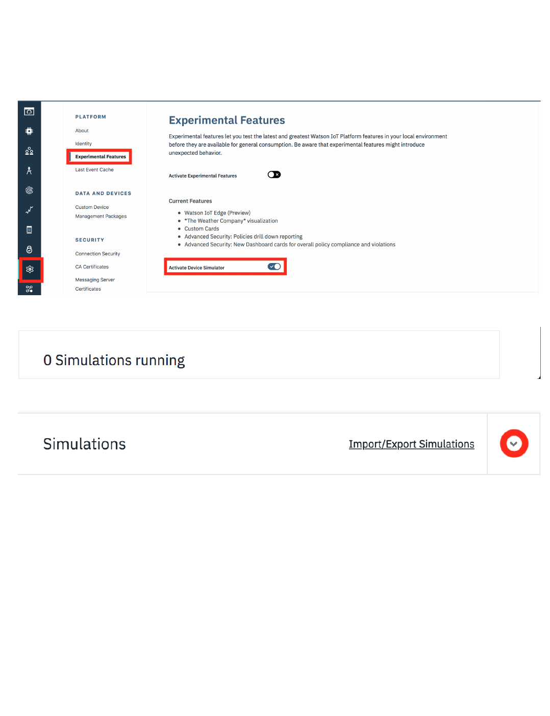
1. Enable the Device Simulator
By default, the device simulator is not enabled on the platform. To enable it:
Switch to the settings section of the Watson IoT Platform console.
Navigate to the Experimental Features settings area.
Enable the Device Simulator.
You should see the device simulator panel appear at the bottom of the IoT console.
You can open the simulator by clicking on the panel and then close the simulator by using the twisty at the top of the simulator window
2. CONFIGURING A DEVICE SIMULATOR
Creating a simulator is a 2 part process:
Create a simulation by selecting or create a device type and then model the data that should be posted when the simulation is running.
Create one or more device simulator instances for that simulation.
To add your first simulation press the Add First Simulation button.
1.
2.
3.
1.
2.
6.3.4 Steps
- 133/145 -
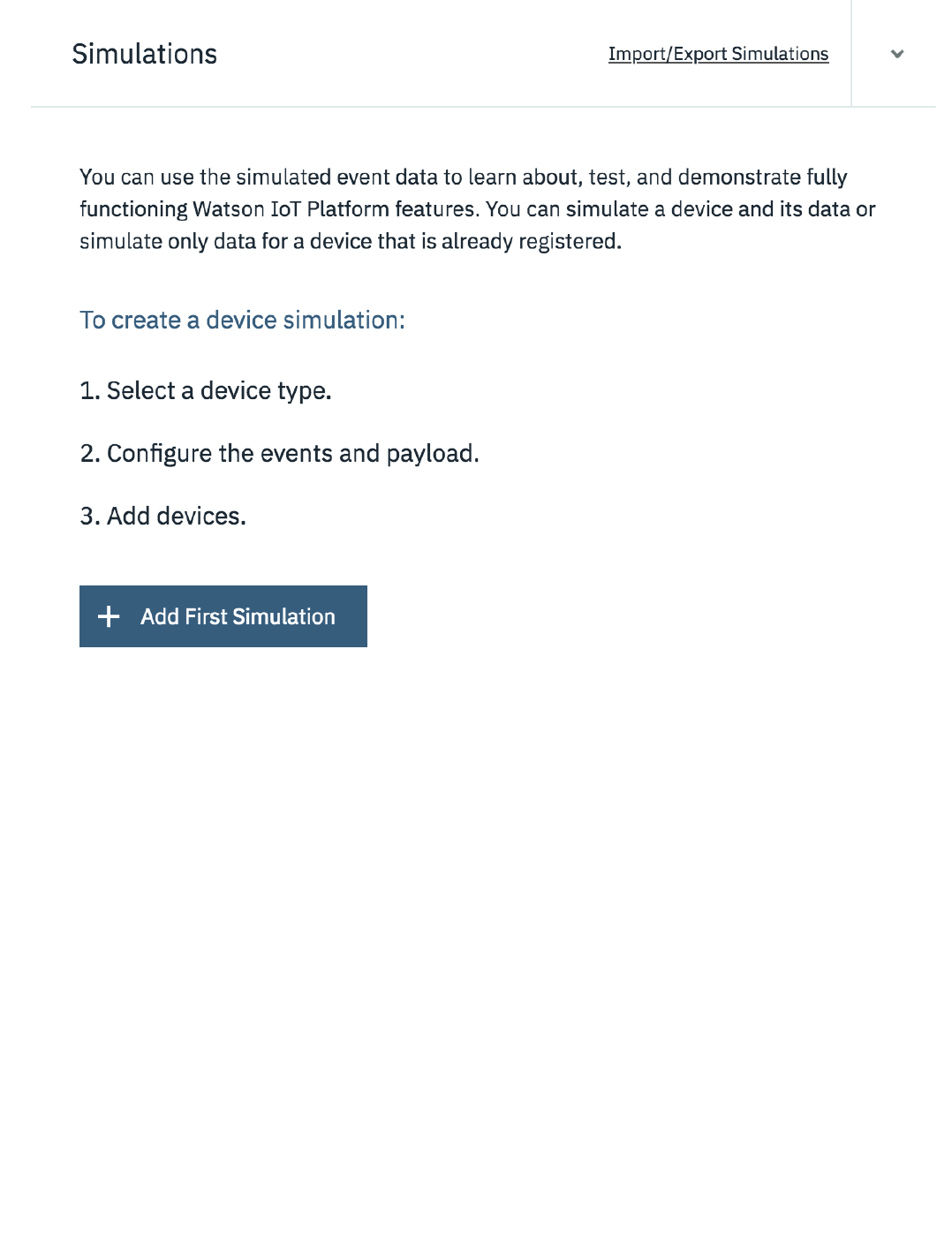
Clicking into the Select or create a device type... field will show any existing device types. You can choose one of the existing device types or you can enter a
device type name here to create a new device type.
6.3.4 Steps
- 134/145 -
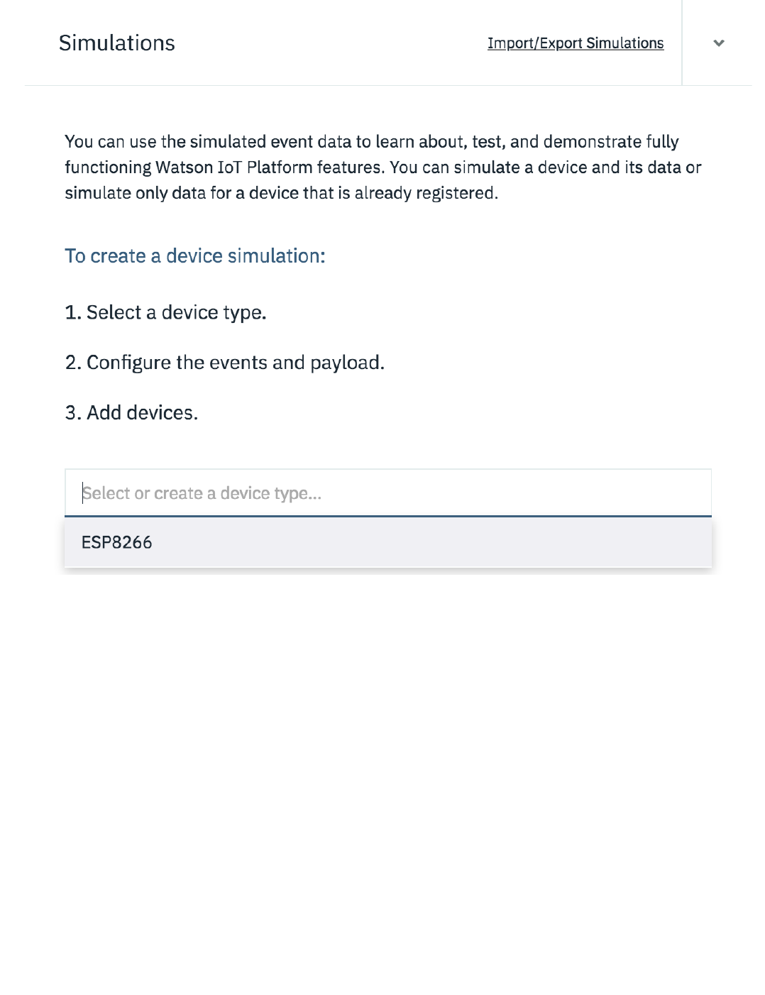
Once the device type has been selected or created you are presented with the panel to configure the data for the simulation.
6.3.4 Steps
- 135/145 -
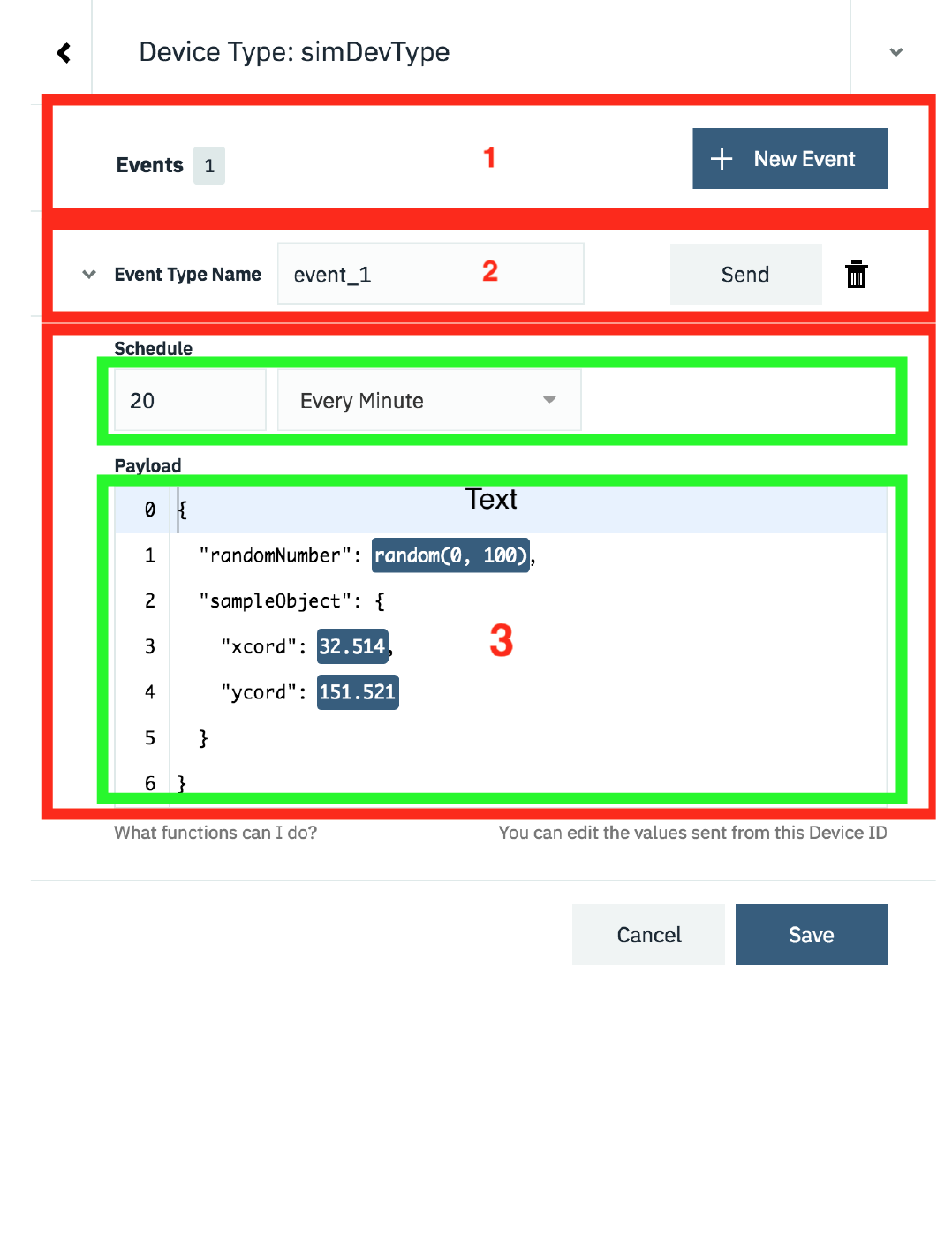
There are 3 areas, as shown in the image above:
1. EVENTS
The simulator provides the ability to define multiple different events that a simulated device can publish. E.g. if you have a device that sends temperature data
every 30 seconds and air quality data every 10 minutes, then you could set up 2 events. 1 for the temperature and 1 for the air quality.
By default a single event is created when a new simulation is created, but additional events can be created using the + New Event button**
Each event has its own schedule and payload content, but all events run when the simulation is running. It is not possible to enable and disable individual events.
If you want that functionality then you need to create multiple simulations.
6.3.4 Steps
- 136/145 -
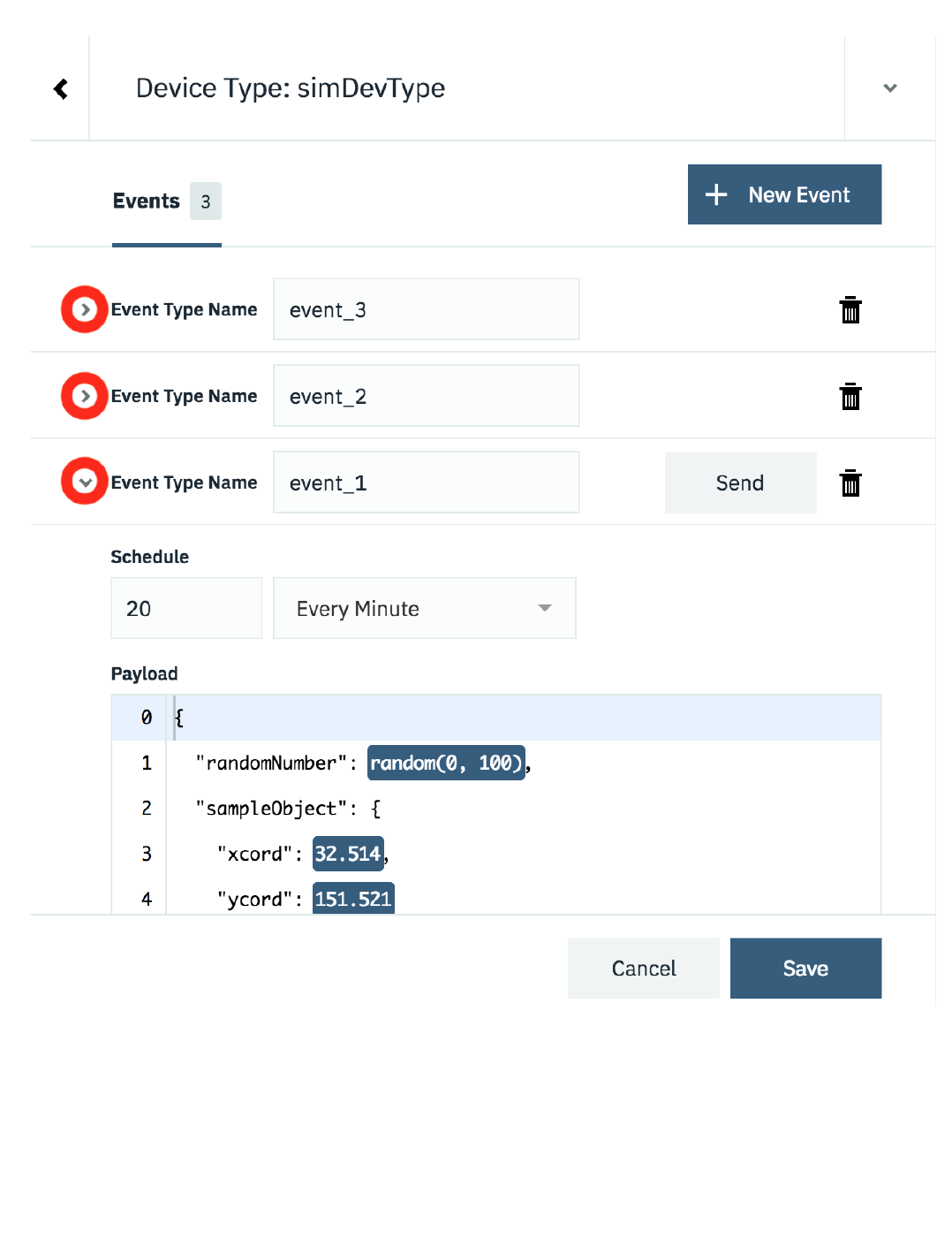
As you add more events the list of events grows. You can expand and collapse the individual events using the twisty.
2. EVENT TYPE NAME
When data is sent from a device to the platform it is sent as a device event message with an event type as one of the fields in the message. Here you can define
the event type that will be sent with the payload for this event
3. EVENT CONTENT AND TIMING
When you expand the section for an event you can specify how often a message is sent and what content is sent as the payload.
The schedule allows you to select a certain number of messages to be sent each minute or each hour. The messages are sent at regular intervals, so 2 messages
per minute will result in a messages being sent every 30 seconds.
6.3.4 Steps
- 137/145 -
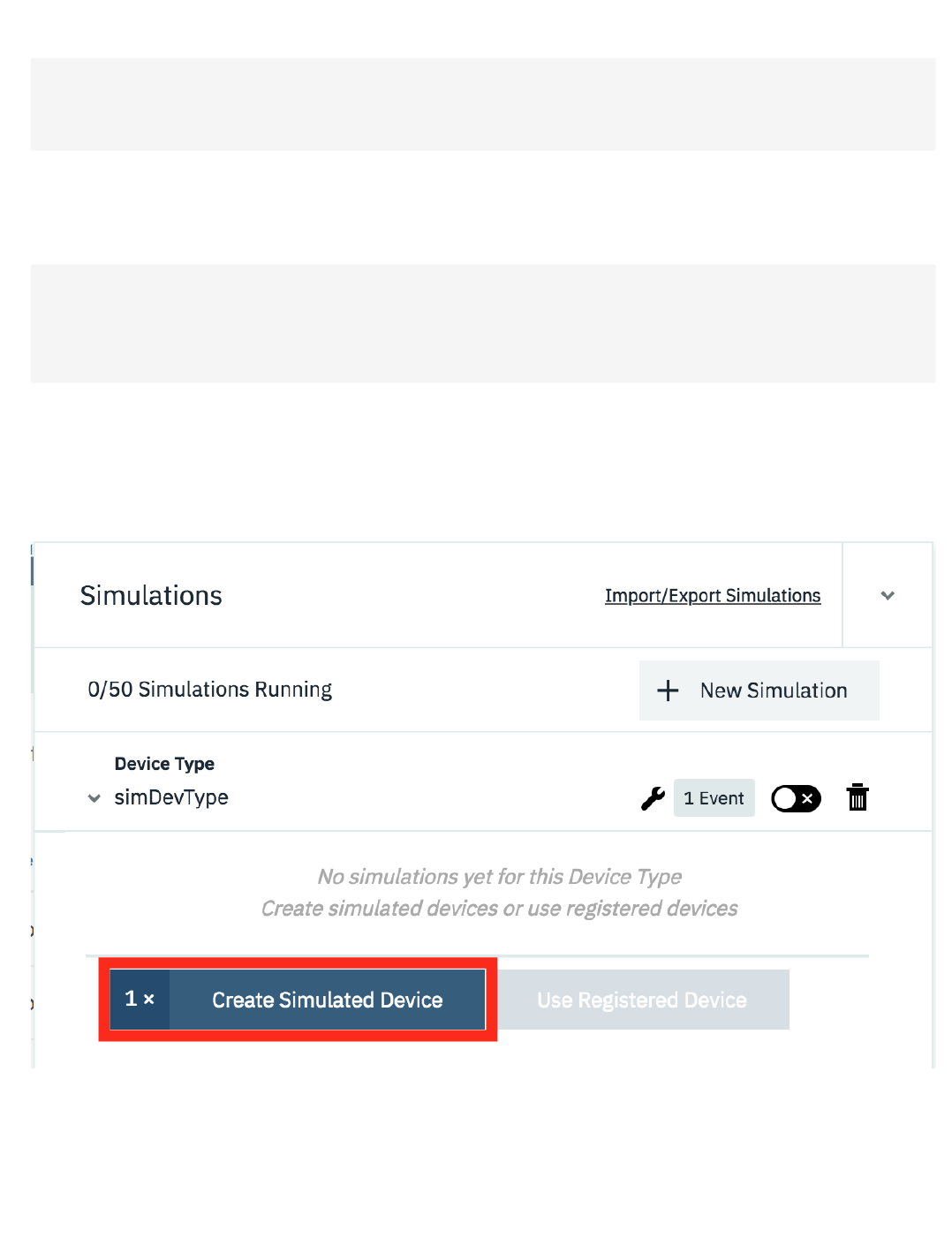
The payload section allows you to define the message format that will be sent. You can define a static message, where every message will have exactly the
same content:
or use one of the 2 options for adding variation to the data sent
range(0,100), will generate a random number between the 2 parameters
$counter, will be contain the total number of devices added in the simulator for this type.
When you have defined all the events, with the correct schedule and data content, press save to save the simulation.
3. Adding simulated Devices
Once you have the simulation defined you can create simulated devices for the simulation. A device can be set to simulate an existing, configured, real device or
register a new device on the platform.
To add a device press the Create Simulated Device button or if you want to simulate an existing device press the Use Registered Device button (this will only
be enabled if there is an available registered device of the correct deviceType to simulate). Once the device is added then the simulated device will immediately
start sending data according to the simulation settings.
You can add as many devices as you desire (up to the displayed limit)
{
"sampleObject"
:
{
"xcord"
:
32.514
,
"ycord"
:
151.521
}
}
•
•
{
"randomNumber"
:
range(
0
,
100),
"total"
:
$counter
,
"sampleObject"
:
{
"xcord"
:
32.514
,
"ycord"
:
151.521
}
}
6.3.4 Steps
- 138/145 -
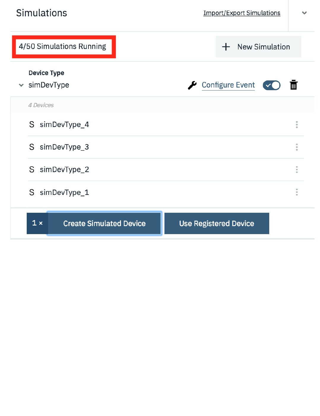
You can control the simulation at the top level using the Device type controls or you can manage each device by expanding the device menu.
6.3.4 Steps
- 139/145 -
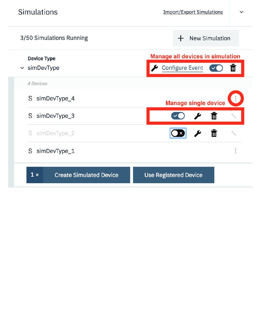
Here you can start and stop individual devices, configure individual devices or delete a simulated device. You are able to customise each device so they all
differ from the simulation configuration. However, if you modify the simulation configuration then you can choose to reset all devices back to the simulation
configuration.
4. Monitoring simulated devices
You can see the state of simulated devices the same way you can monitor real devices using the devices section of the IoT console.
6.3.4 Steps
- 140/145 -
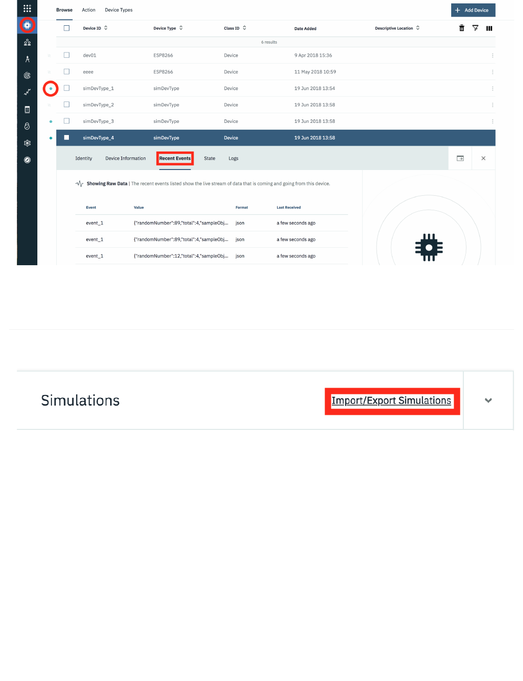
You can see when a simulator is active as it shows as a connected device, then expanding the device you can select the Recent Events section to see the
individual events being received.
6.3.5 Saving simulation configuration
The platform allows you to export your simulation configuration to the clipboard or download it as a JSON file. You can then import a simulator configuration
from the clipboard or file. This allows you tp share a simulator configuration, so others can replication your simulator setup.
When importing a device configuration the deviceType and devices are not automatically created, so you need to create them in advance or use the
troubleshooting option to have the devices and deviceTypes created:
To open up the troubleshooting section click in the event info section at the bottom of the simulator panel:
6.3.5 Saving simulation configuration
- 141/145 -
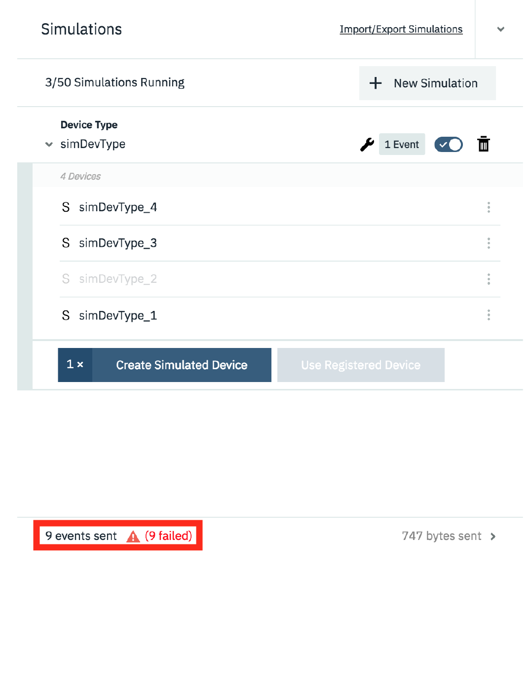
This will then show a log of events and offer to troubleshoot failing events:
6.3.5 Saving simulation configuration
- 142/145 -
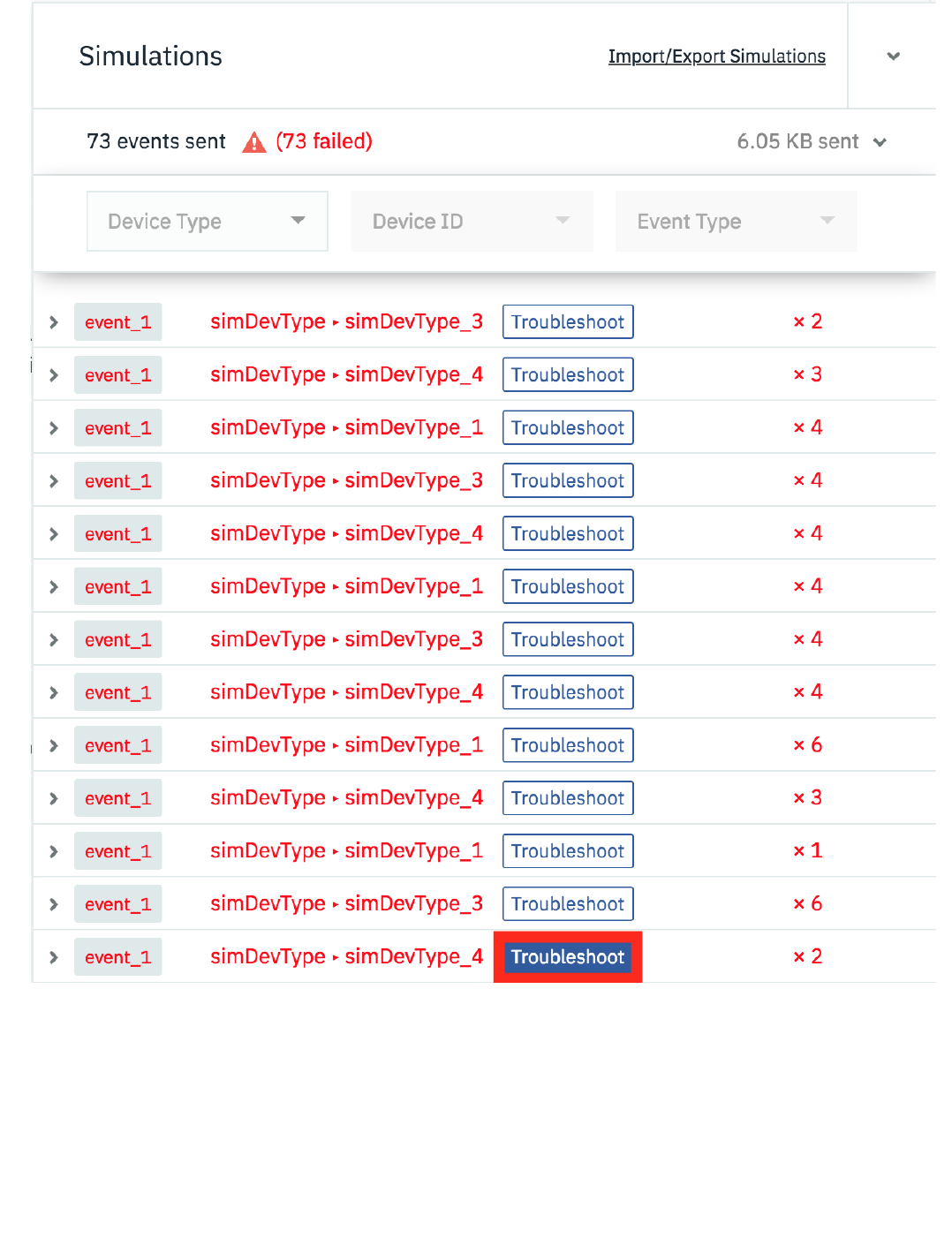
Select the Troubleshoot button next to one of the failing events and you will have the option to diagnose the issue. Press the Run Diagnostics button to get the
simulator to determine the cause of the error:
6.3.5 Saving simulation configuration
- 143/145 -
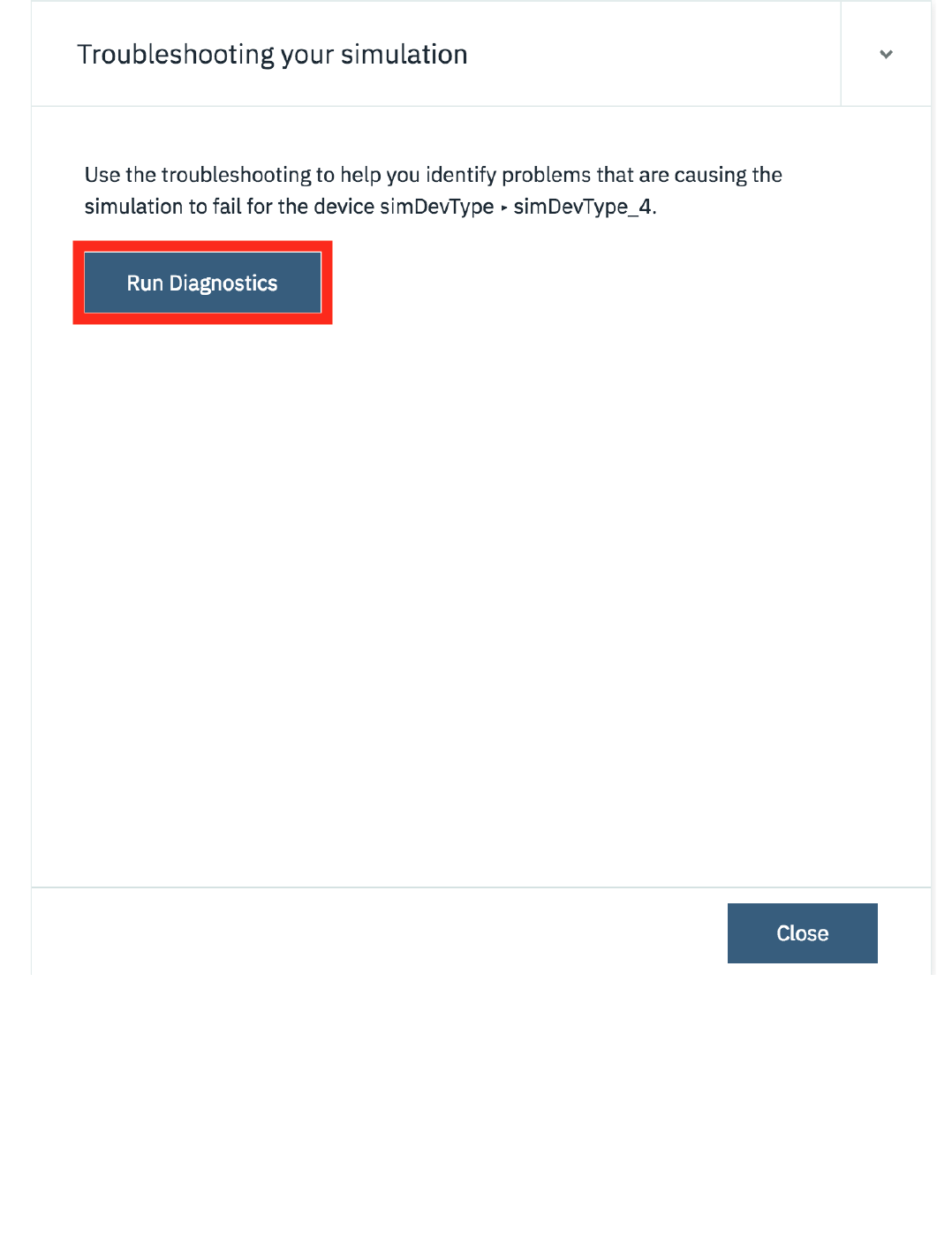
The result of the diagnostics will be shown and if there are missing deviceTypes and devices the platform will offer to create the missing configuration:
6.3.5 Saving simulation configuration
- 144/145 -
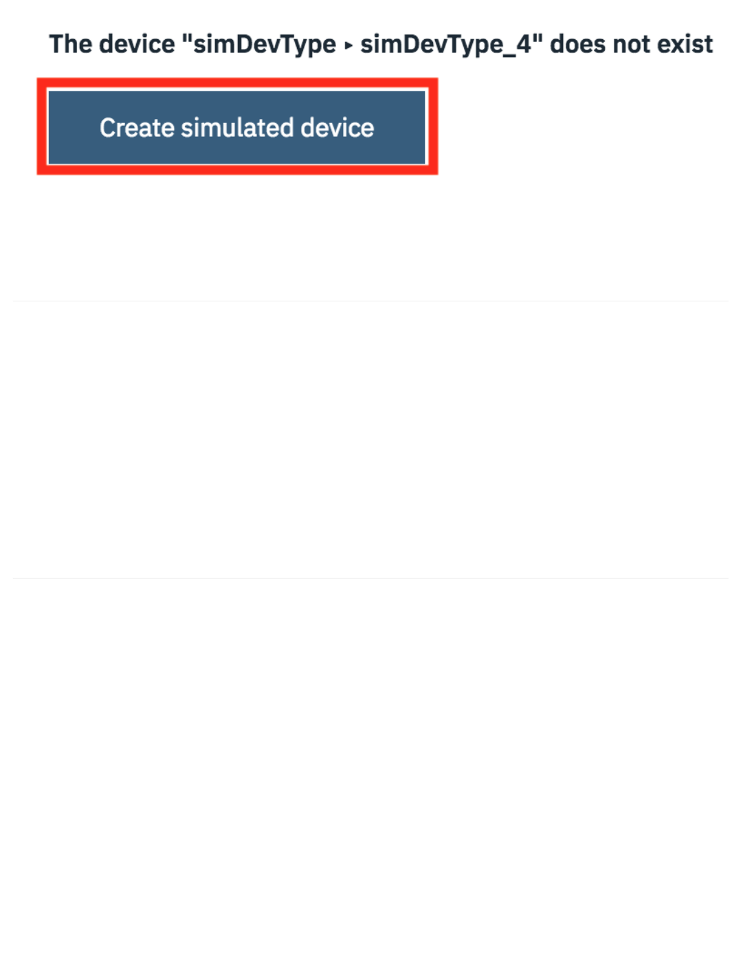
You can repeat this for all the devices imported to the simulator.
To clear the simulator event log, you can go into the settings panel and disable then enable the simulator. The configuration will not be lost, but the simulator
will be restarted, clearing the event log.
6.3.6 Limitations of the Device Simulator
The Simulator is still an experimental feature on the IoT Platform, so there are a few limitations.
There is a limit to the number of concurrent simulated devices which can be run. This is shown at the top of the simulation panel
You cannot have multiple simulations running concurrently for the same device.
The simulator will not work when user certificates have been added to the IoT platform configuration. If you have certificates configured or even just
uploaded then the simulator will fail to connect. If you want to remove certificates, goto the settings section of your Watson IoT Platform console and follow
the following steps:
Goto the Connection Security section then select Open Connection Security Policy. Ensure no rules are configured to use certificates. TLS with Token
Authentication or TLS Optional should be selected for all rules.
Goto the Messaging Server Certificates section of the platform settings and ensure the Default Certificate is selected as the active certificate. You can
then select any imported certificates and then delete them.
Goto the CA Certificates section of the platform settings and delete any imported certificates.
6.3.7 Summary
This guide has shown you how to enable the device simulator and setup simulators to create device data. The device simulator is a great tool to be able to test
error or failure conditions that are difficult to create using live data from a real device.
Remember to turn off simulators when not needed to ensure you do not use up free limits on the IBM Cloud or incur additional expense if on a paid plan.
•
•
•
•
•
•
6.3.6 Limitations of the Device Simulator
- 145/145 -
