
INSPECTION & CLEANING
INSTRUCTIONS
3M™ SCOTT™ AIR-PAK™ X3 PRO
Self-Contained Breathing Apparatus (SCBA)
CGA & SNAP-CHANGE
Pressures 2.2, 4.5, 5.5
READ ALL INSTRUCTIONS BEFORE USE
P/N 595360-01 Rev G 202004
All information, illustrations, and specifications in this manual are based on the latest product information available at
the time of publication. 3M reserves the right to make changes at any time without notice.
The contents of this manual may not be used, reproduced, or disclosed to any third party in whole or in part without
obtaining express written permission and authorization from 3M.
Cautionary Notice
While the manufacturer has attempted to detail in this manual all areas of possible danger to personnel in connection
with the use and servicing of this equipment, personnel should use caution when installing, inspecting, operating, and
servicing this equipment, especially when handling pressurized air cylinders. When maintaining or operating all
electronic equipment, care should be taken to avoid electrical shock in all circuits where substantial currents or
voltages may be present through design or component failure. Caution should be observed in lifting and hoisting
heavy equipment.
The manufacturer is specifically not liable for any damage or injury arising out of a user’s failure to follow the
instructions contained in this manual or failure to exercise due care and caution in the installation, operation,
inspection, and service of this equipment.
Import and Export
The international transport of this equipment and any related documentation is regulated under United States export
laws and regulations and may be regulated by the import or export laws and regulations of other countries.
If you have any questions or concerns regarding these regulations, contact 3M at 1-800-247-7257 (704-291-8300
outside the continental United States).
Questions or Concerns
If you have any questions or concerns regarding use of this equipment, contact your authorized 3M distributor, or
contact 3M at 1-800-247-7257 (704-291-8300 outside the continental United States) or
For all National Fire Protection Association (NFPA)-compliant versions of this respirator, report any operational
malfunctions to the certification agency Safety Equipment Institute (SEI), 1307 Dolley Madison Blvd, Suite 3A,
McLean, VA 22101, (703) 442-5732, Fax (703) 442-5756.
For all National Institute for Occupational Safety and Health (NIOSH)-compliant versions of this respirator, report
any complaints of damage, malfunction or failure of the breathing apparatus that may represent a hazard to the user
to the certification agency NIOSH/NPPTL/Respirator Branch, P.O. Box 18070, Pittsburgh, PA 15236, (412)
386-4000.

P/N 595360-01 Rev G 202004 3
Contents
About This Manual ...................................................................................................................... 5
Intended Readers........................................................................................................................................5
How to Read This Manual ........................................................................................................................5
Warnings, Cautions, and Notes .......................................................................................................5
Before You Begin ........................................................................................................................................6
Maintenance and Repairs ..................................................................................................................6
Respirator Testing ...............................................................................................................................6
Retirement Criteria and Considerations ........................................................................................ 7
Safety Information ...................................................................................................................... 9
All 3M Scott Fire & Safety Products......................................................................................................9
3M Scott Air-Pak SCBAs..........................................................................................................................9
Chapter 1 Inspecting the Respirator ............................................................................................................11
Before You Begin ....................................................................................................................................... 11
Inspecting the Respirator Components...............................................................................................12
Performing a General Inspection ...................................................................................................12
Inspecting the Breathing Air Cylinder .......................................................................................... 13
Inspecting the RIC/UAC Connection .......................................................................................... 14
Inspecting the Facepiece ................................................................................................................ 15
Inspecting the Regulator ..................................................................................................................17
Performing Operational Testing............................................................................................................ 19
General Testing .................................................................................................................................. 19
Testing the Regulator ...................................................................................................................... 20
Testing the Heads-Up Display ........................................................................................................21
Testing the Sensor Module Lights ................................................................................................23
Testing the Batteries .........................................................................................................................24
Chapter 2 Soft Goods Assembly & Disassembly ..................................................................................... 25
Detaching the Shoulder Harness and Waist Pad..............................................................................25
Attaching the Shoulder Harness and Waist Pad...............................................................................32
Chapter 3 Cleaning & Storing the Respirator ............................................................................................41
Before You Begin ...................................................................................................................................... 41
Cleaning the Respirator...........................................................................................................................42
Cleaning the Facepiece ...................................................................................................................42
Cleaning the Mask-Mounted Regulator ..................................................................................... 44
Cleaning the Shoulder Harness and Waist Pad .........................................................................47
Spot Cleaning the Shoulder Harness and Waist Pad ........................................................................... 47
Machine Washing the Shoulder Harness and Waist Pad .................................................................. 48
Drying the Shoulder Harness and Waist Pad......................................................................................... 49
Storing the Respirator............................................................................................................................. 50
Chapter 4 Replacing Batteries ......................................................................................................................51
Before You Begin ...................................................................................................................................... 51
Replacing Batteries in Respirators with PASS................................................................................... 51
P/N
Rev G
202004
4 P/N 595360-01 Rev G 202004

P/N 595360-01 Rev G 202004 5
ABOUT THIS MANUAL
This manual provides inspection and cleaning instructions for the 3M Scott Air-Pak X3 Pro SCBA.
Intended Readers
3M provides manuals for individuals with different levels of training. This manual is written for Trained Operators.
• A Trained Operator is an individual who has had minimum-level training in the use of 3M Scott Fire & Safety
equipment in an immediately dangerous to life or health (IDLH) environment. This individual is often a firefighter
or the wearer of an SCBA. He or she is familiar with the instructions provided in this manual and is capable of
performing basic maintenance tasks (e.g., replacing batteries) as outlined.
• A Certified Technician is an individual who has successfully completed the Air Supplied Certified Technician II
class offered by 3M. Certified technicians are able to use specialized equipment, including the Posi 3 USB™
1
SCBA testing equipment, and are able to make repairs to the SCBA that involve the air flow path.
How to Read This Manual
Warnings, Cautions, and Notes
Throughout this manual, special references are made when deemed important. The following classifications
distinguish these references by their level of importance:
1. Posi3 USB is a trademark of Honeywell Analytics, Inc., Lincolnshire, IL.
WARNING
Indicates a hazardous situation which, if not avoided, could result in serious injury or death
CAUTION
Indicates a hazardous situation which, if not avoided, could result in minor or moderate injury and/or
property damage
NOTE
Indicates a situation which, if not avoided, could result in property damage
TIP
Indicates helpful information
P/N 595360-01
202004
Rev G

6 P/N 595360-01 Rev G 202004
Before You Begin
Before beginning any procedures, review the manual in its entirety. Thoroughly read all warnings, cautions, and
notes. Acquire all tools and materials listed before beginning any procedure. When performing any maintenance
checks or services on any 3M Scott Fire & Safety product or device, proceed only as far as necessary and as
instructed by this manual.
Maintenance and Repairs
Comply with all instructions and warnings contained in all applicable manuals.
It is your responsibility to obtain and use the most current instructions that apply to the operations being performed.
The instructional material must include the most current materials: manuals or manual modules, Operation and
Maintenance Instructions, Inspection and Cleaning Instructions, Installation and Use Instructions, and any additional
3M-approved support material required to maintain the equipment.
Current service literature is available from 3M. The Certified Technician I Maintenance Training Manual contains
additional maintenance information that goes beyond the routine cleaning and regular operational inspection of the
equipment but is less advanced than Certified Technician II-level maintenance available at a 3M Authorized Service
Center. A person with good mechanical ability using standard hand tools is capable of performing Technician I-level
tasks. Contact 3M or your 3M distributor for details.
Because this equipment may be used to support human life in a hazardous atmosphere, do not attempt maintenance
beyond that described in this instruction or in the Certified Technician I Maintenance Training Manual. If disassembly
or adjustment other than described in this manual or the Certified Technician I Maintenance Training Manual is
required, the equipment must be serviced by a 3M Scott Authorized Service Center in accordance with the
appropriate 3M Scott Fire & Safety Technician Service Manuals. You can arrange service by an Authorized Service
Center through your authorized 3M distributor or by contacting 3M.
If you note a discrepancy while performing operation or maintenance checks and services, tag the equipment as “Out
of Service” and refer it to a 3M Certified Technician II.
While an attempt has been made to address all foreseeable operation/service conditions, exercise careful judgment
in removing from service any equipment that does not appear to function correctly, even if all operator-level
maintenance checks and services have been completed. If there is any doubt regarding the safe operation of the
equipment, remove it from service and tag it for repair.
Respirator Testing
3M recommends that this respirator be inspected and tested by a 3M Scott Authorized Service Center using 3M
Authorized Test Equipment at least once a year. Heavy use and/or severe service conditions may require more
frequent inspection and testing. This recommendation is in addition to all other cleaning and maintenance procedures.
In addition, all air cylinders used with 3M Scott Fire & Safety respirators must be periodically visually inspected and
hydrostatically tested by a licensed cylinder retester. The cylinder inspection and test must be done in accordance
with the appropriate U.S. Department of Transportation (DOT) specification or the applicable DOT exemption.
• Composite fiber overwrapped cylinders must be tested up to their maximum life which, at the time of the
publication of this manual, is 15 years from the date of manufacture. It is the responsibility of your organized
respiratory protection program to arrange for visual inspection and hydrostatic testing of cylinders by a licensed
retester.
• Intervals for hydrostatic testing are established in the appropriate U.S. Department of Transportation (DOT)
specification or applicable DOT exemption, or in the appropriate Transport Canada (TC) Permit of Equivalent
Level of Safety. Refer to the current revision of Safety Precautions for Air-Pak Cylinders, P/N 89080-01, available
upon request from 3M.
BEFORE YOU BEGIN
P/N 595360-01 Rev G 202004 7
Retirement Criteria and Considerations
Retirement criteria and considerations to be determined by technicians with Certified Technician II qualifications in
accordance with NFPA 1852.
8 P/N 595360-01 Rev G 202004

P/N 595360-01 Rev G 202004 9
SAFETY INFORMATION
Read all of the safety information before beginning any of the procedures in this manual. The safety information in
this section is organized as follows:
• “All 3M Scott Fire & Safety Products” on page 9
• “3M Scott Air-Pak SCBAs” on page 9
All 3M Scott Fire & Safety Products
The following safety directives apply to all 3M Scott Fire & Safety products.
• Many 3M Scott Fire & Safety products are intended to support human life in hazardous atmospheres. Failure to
carefully read, understand, and follow the instructions and warnings in this manual may result in serious injury or
death.
• Improper use of this equipment may result in serious injury or death. Improper use includes, but is not limited to,
use without adequate training, disregard of the warnings and instructions contained herein, use of the equipment
for purposes not included in these instructions, and failure to inspect and maintain the equipment.
• Apply only the instructions offered within this manual. Maintenance procedures beyond the scope of this manual
must not be performed. Additional disassembly may cause operation errors and/or component failure and result
in serious injury or death. If a discrepancy or malfunction cannot be corrected using the procedures contained
within this manual, the product must be tagged to indicate that it is unserviceable and referred to a 3M Certified
Technician II for evaluation and repair.
• Exercise caution when using chemicals. Prior to using any chemical substance, thoroughly review and understand
the product label, Safety Data Sheet (SDS), and manufacturer’s use instructions. Chemical substances may
present serious hazards such as flammability and human-specific health hazards, which can affect the nervous
and reproductive systems. Failure to adhere to the manufacturer’s product instructions and warnings may result
in serious injury or death.
• Comply with all instructions and warnings contained in this and all applicable manuals and modules. While an
attempt has been made to address all foreseeable operating conditions, you must exercise careful judgment
when operating any equipment. If there is any doubt regarding the safe operation of equipment, remove the
equipment from service and tag it for repair.
• Failure to use 3M-approved lubricants and replacement parts will invalidate all certifications and warranties
issued to the 3M Scott Fire & Safety product.
• You are responsible for any damage, improper function, or injury as a result of user-applied markings, etchings,
labeling, material additions, or modifications to the equipment.
3M Scott Air-Pak SCBAs
The following safety directives, warnings, and cautions apply to 3M Scott Air-Pak SCBAs.
• Improper use of this respirator may result in serious injury or death. Improper use includes, but is not limited to,
use without adequate training, disregard of the warnings and instructions contained herein, and failure to inspect
P/N 595360-01
202004
Rev G
10 P/N 595360-01 Rev G 202004
and maintain this respirator. Read and understand all instructions before attempting to operate or service this
equipment.
• The information in this instruction is meant to supplement — not replace — the instructions, training, supervision,
maintenance, and other elements of your organized respiratory protection program.
• Use this respirator only in conjunction with an organized respiratory protection program that complies with the
requirements of the following:
• American National Standard Practices for Respiratory Protection, Z88.2, current edition, available from
American National Standards Institute, Inc., 1430 Broadway, New York, NY, 10018
• OSHA Safety and Health Standard 29 CFR 1910, Paragraph 134, available from the US Department of Labor,
Occupational Safety and Health Administration
• Other pertinent nationally recognized standards, such as those of the US Coast Guard or the Department of
Defense
• This product is designed and intended to function properly in reasonable/ordinary firefighting conditions. The
functionality of this product may be compromised by extreme fire conditions.
• Training is required before use of this respirator. Use this respirator only if you have been trained in its use and
only in conjunction with an organized respiratory protection program. Do not use this respirator for purposes
other than those authorized by your respiratory protection program. Do not use this respirator underwater.

P/N 595360-01 Rev G 202004 11
P/N 595360-01
202004
Rev G
CHAPTER 1
INSPECTING THE RESPIRATOR
This chapter describes how to perform a regular operational inspection of a 3M Scott Air-Pak X3 Pro SCBA. Follow
the procedures in this chapter when you first receive the SCBA and during daily or periodic inspection of the SCBA:
• “Before You Begin” on page 11
• “Inspecting the Respirator Components” on page 12
• “Inspecting the Breathing Air Cylinder” on page 13
• “Inspecting the RIC/UAC Connection” on page 14
• “Inspecting the Facepiece” on page 15
• “Inspecting the Regulator” on page 17
• “Performing Operational Testing” on page 19
• “General Testing” on page 19
• “Testing the Regulator” on page 20
• “Testing the Heads-Up Display” on page 21
• “Testing the Sensor Module Lights” on page 23
• “Testing the Batteries” on page 24
Before You Begin
Below is a summary of the requirements and recommendations for operational inspections of respirators:
• Inspect the respirator before each use and after each cleaning. (Clean the respirator after each use. See
“Chapter 3: Cleaning & Storing the Respirator” on page 41.)
• Inspect respirators for emergency use as frequently as required to ensure the respirator will function properly.
The Occupational Safety and Health Administration (OSHA) of the U.S. Department of Labor requires at least
monthly inspection of respirators for emergency use (29 CFR 1910.134).
• The National Institute for Occupational Safety and Health (NIOSH) recommends an inspection for cylinder
pressure at least weekly.
Storage conditions at your location or the regulations that apply to your respiratory protection program may require
more frequent periodic inspections.
WARNING
Follow the regular operational inspection procedures exactly as written. If the respirator does not operate as
described or if any other operational malfunction is noted, do not use the respirator. Remove it from service
and tag it for repair by authorized personnel. Failure to properly inspect the respirator may result in serious
injury or death.

INSPECTING THE RESPIRATOR
12 P/N 595360-01 Rev G 202004
Inspecting the Respirator Components
Inspect the respirator before each use and after each cleaning.
Performing a General Inspection
To inspect the respirator
1 Inspect the complete respirator for worn or damaged components.
a Inspect hoses and rubber parts for cracking, splitting, or brittleness.
b Inspect the harness webbing and all elastomeric components for cuts, tears, abrasion, fraying, or indication of
heat or chemical damage.
c Check all buckles and fasteners for proper operation.
d Check the cylinder retention system for damage and for proper operation.
e Verify that the respirator has been properly cleaned.
2 Verify that the shoulder harness assembly and waist pad are firmly attached to the backframe.
a Check that all harness sleeves are firmly fastened.
b Verify that the regulator hose, console cable, and gaugeline are properly routed through the harness sleeves.
3 Inspect the pressure reducer for damage. Verify that the pressure reducer is securely mounted to the
quarter-turn mount on the backframe.
4 Inspect the mask-mounted regulator for damaged or missing components.
a Remove the mask-mounted regulator from the facepiece by pulling back on the regulator latch and rotating
the regulator one-quarter turn.
b Verify that the regulator gasket is in place around the outlet port of the regulator. Inspect the gasket for rips or
damage that may break the seal.
c Verify that the purge valve (red knob) is not damaged and turns smoothly one-half turn from stop to stop.
5 If you have an approved voice amplifier or other communications device, refer to the user instructions provided
with that device for details about maintenance and operational testing. Always confirm that the device has fresh
batteries before use.
WARNING
Clean and inspect the respirator before storing it. Do not store a respirator with worn or damaged
components. Replace worn or damaged components during inspection or remove the respirator from
service and tag it for repair by authorized personnel. Use of a respirator with worn or damaged components
may result in serious injury or death.
WARNING
Failure to follow these instructions may reduce respirator performance, overexpose you to contaminants,
and may result in injury, sickness, or death.

INSPECTING THE RESPIRATOR COMPONENTS
P/N 595360-01 Rev G 202004 13
Inspecting the Breathing Air Cylinder
Inspecting the cylinder includes looking for physical damage, noting the hydrostatic test date, and inspecting the
cylinder valve, including the hand wheel, outlet, connector, and relief valve.
To inspect the breathing air cylinder
1 Visually inspect the breathing air cylinder and valve assembly for physical damage such as dents or gouges in the
metal or the composite wrapping.
Physical damage to breathing air cylinders from high heat, flame, or chemical exposure includes the following:
• Discoloration or paint that has turned brown or black
• Charred or missing decals
• Melted pressure gauge lens
• Distorted elastomeric bumper
• Cracks in the cylinder or the composite wrapping
• Peeling of the outer layers of the composite wrapping
• Bulging of the cylinder wall
If a cylinder shows any of the physical defects listed, remove it from service and empty it of compressed air.
2 Check the latest cylinder hydrostatic test date to ensure it is current.
The date of manufacture marked on the cylinder is also the date of the first hydrostatic test. All breathing air cyl-
inders used with 3M Scott Air-Pak SCBAs must be visually inspected regularly and hydrostatically tested at the
required intervals by a licensed cylinder re-tester. For more information about hydrostatic testing, see “Respirator
Testing” on page 6.
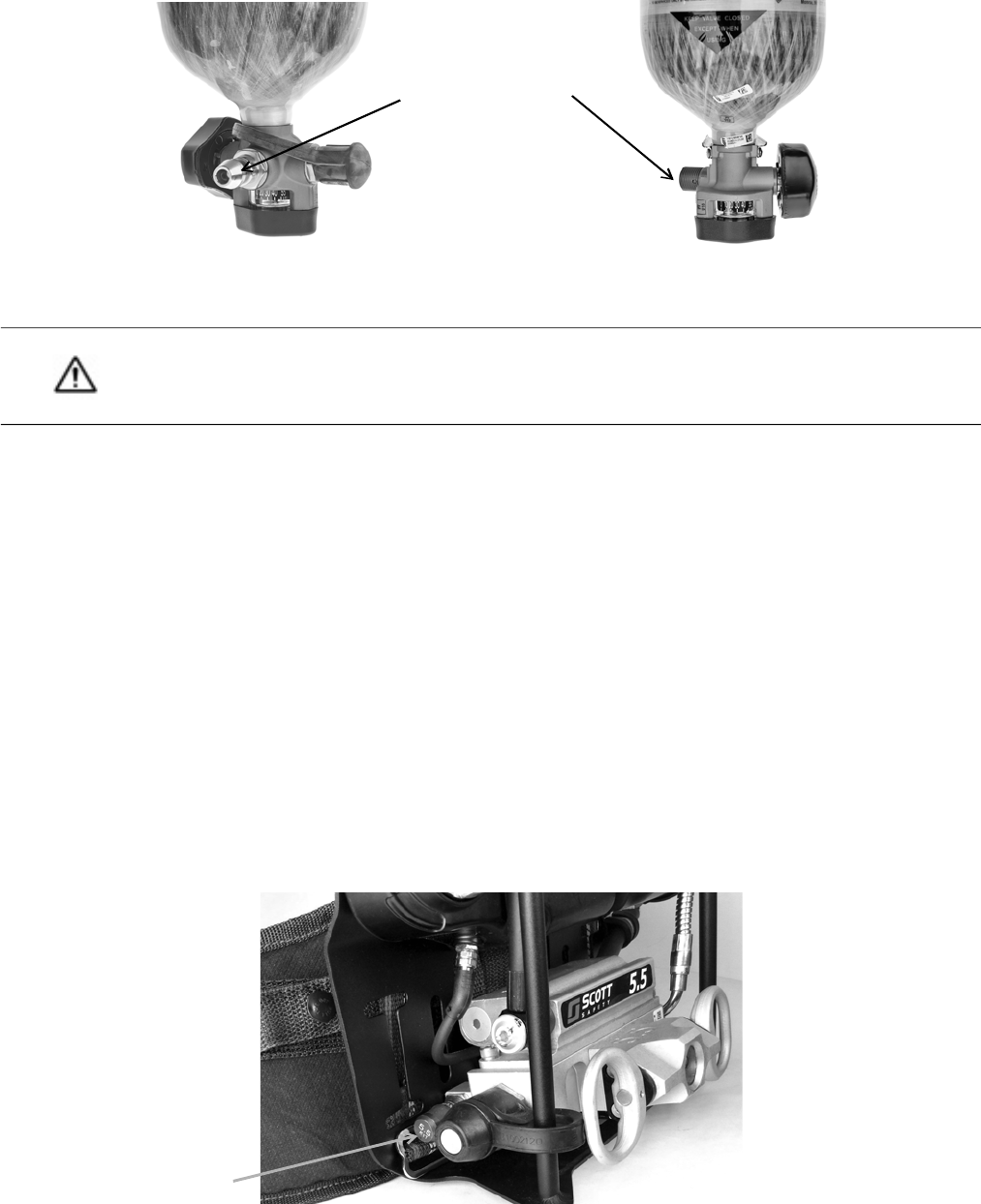
3 Inspect the cylinder valve (see Figure 1-1).
a Check for damage of the cylinder valve hand wheel.
b Inspect the cylinder valve outlet for damage.
c Verify that the CGA threads or Snap-Change connector on the cylinder valve outlet is undamaged and free of
dirt and debris.
d Check the relief valve (burst disc) for damage or dirt.
WARNING
Damaged cylinders may suddenly leak or rupture if left charged with compressed air. Failure to inspect
cylinders for damage and to empty the air from damaged cylinders may result in serious injury or death.
NOTE
Publications on compressed gas cylinder inspection procedures are available from Compressed Gas
Association, Inc.
INSPECTING THE RESPIRATOR
14 P/N 595360-01 Rev G 202004
Figure 1-1 Inspecting the breathing air cylinder
4 Check the cylinder pressure gauge. If the cylinder is less than full, replace it with a fully charged cylinder.
For information about charging cylinders, see the current revision of Safety Precautions for Air-Pak Cylinders (P/N
89080-01).
Inspecting the RIC/UAC Connection
3M Scott Air-Pak X3 Pro respirators are fitted with a Rapid Intervention Crew/Company Universal Air Connection
(RIC/UAC) system to provide emergency replenishment of an approved SCBA breathing air supply cylinder from an
approved air supply source.
To inspect the RIC/UAC connection
1 Remove the dust cap from the RIC/UAC coupling on the respirator.
2 Visually inspect the coupling for dirt or damage. Remove any dirt or contamination from the coupling. See
Figure 1-2.
a If the RIC/UAC coupling on the respirator appears damaged, remove the respirator from service and tag it for
repair by authorized personnel.
b If you find no damage, replace the dust cap.
Figure 1-2 Inspecting the RIC/UAC connection
CAUTION
Do not use tools to close the cylinder valve. Over-tightening the cylinder valve may cause damage that could
result in air leaking from the cylinder.
Verify that the cylinder connector is
undamaged and free of dirt and
debris.
Cylinder valve with Snap-Change connector
Cylinder valve with CGA connector
RIC/UAC Relief Valve
INSPECTING THE RESPIRATOR COMPONENTS
P/N 595360-01 Rev G 202004 15
Inspecting the Facepiece
Remove and keep the protective static cling label attached to the lens of a new facepiece; the label may be re-used
during storage of the facepiece.
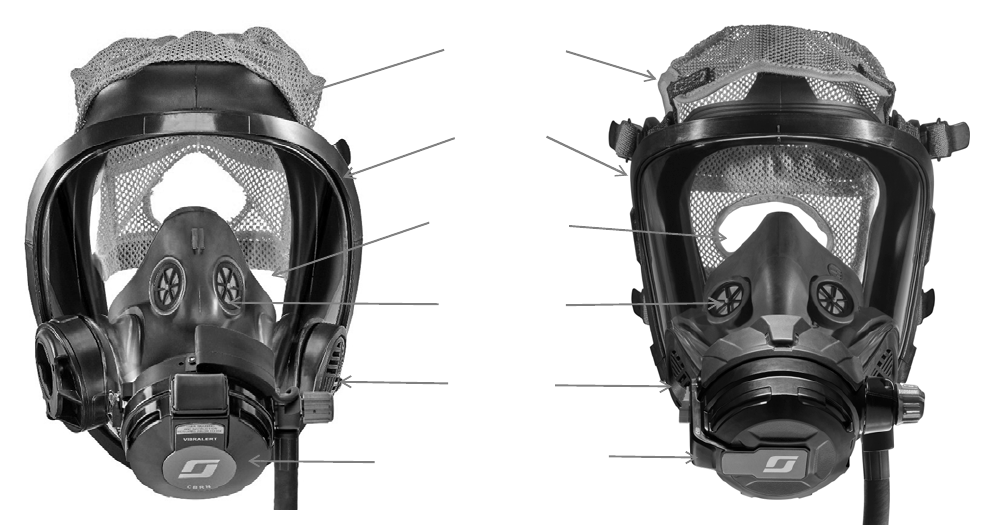
The facepiece must be complete and in serviceable condition with no worn, loose, or damaged components. See the
main components of the facepiece in c.
Figure 1-3 Facepiece components
To inspect the facepiece
1 Inspect the facepiece seal and other rubber components for deformation, wear, cracks, or other damage.
2 Inspect the lens and lens frame.
a Inspect the lens for scratches, gouges, cracks, crazing, distortion, melting, or any other damage or condition
that could impair the user’s vision or the operation of the facepiece.
b Inspect the lens frame for damage such as cracks or distortion.
c Verify that the lens frame screws are present and installed correctly.
3 Inspect the head harness.
a Check that all harness anchors are present and operating properly.
b Inspect the head harness for correct installation with all straps oriented correctly.
c Inspect the head harness for damage or worn components.
4 Inspect the voicemitter ducts.
a Verify that the voicemitter ducts are properly installed.
b Inspect the voicemitters for damage and verify that the voicemitters are properly installed and secure in the
voicemitter ducts.
Head Harness
Nose cup with
inhalation valves
Lens Frame
(Bezel)
E-Z Flo+
Regulator
Voicemitter
Lens (Fenestra)
AV-3000 HT
VISION C5
E-Z-Flo C5
Regulator
INSPECTING THE RESPIRATOR
16 P/N 595360-01 Rev G 202004
5 Inspect the nose cup.
a Inspect the nose cup for cuts or damage. Look for any signs of damage to the facepiece port side of the nose
cup where the regulator attaches.
b Verify that both inhalation valves in the nose cup are present and properly installed.
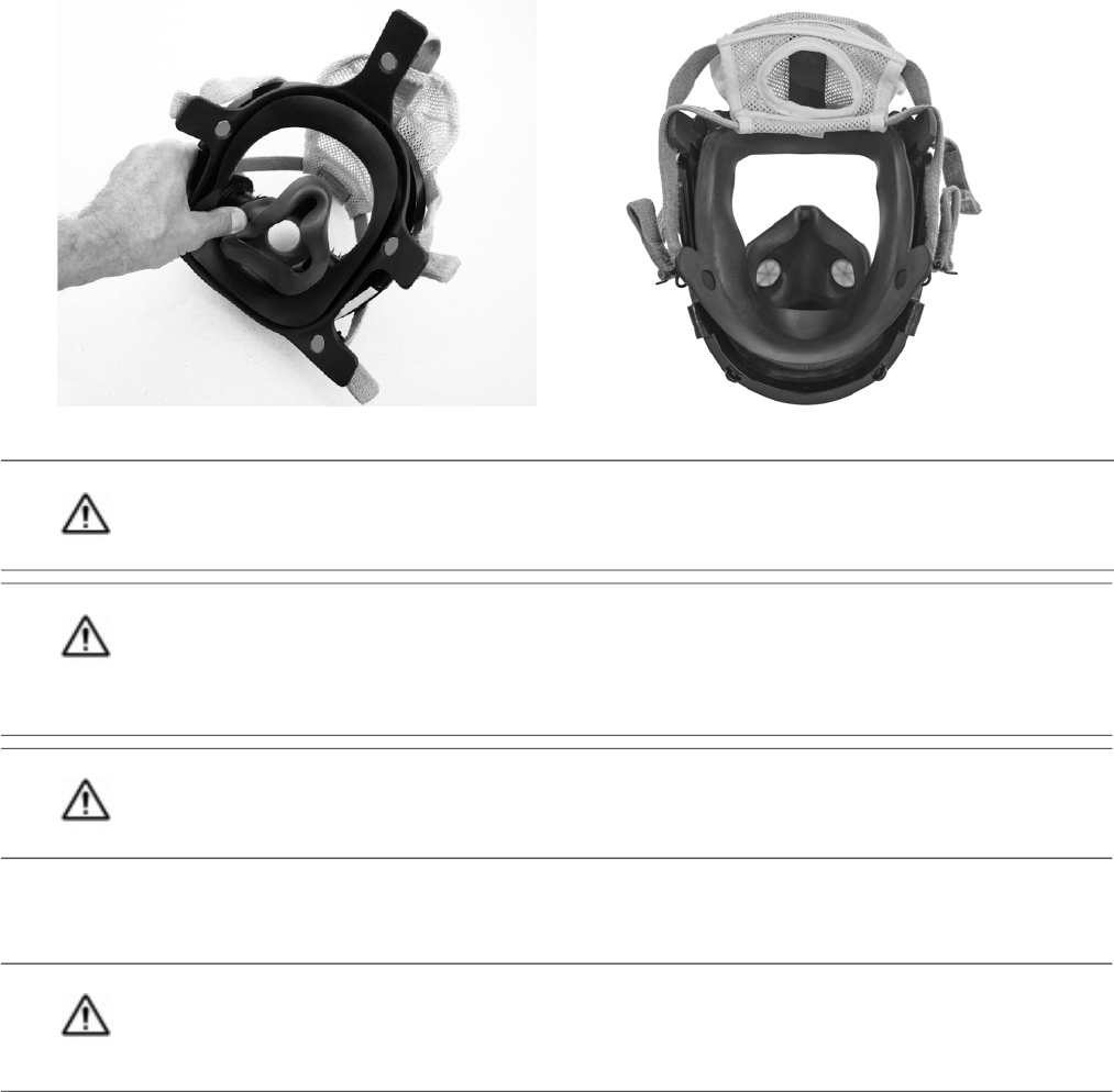
c Verify that the nose cup is properly installed. Check that the nose cup is properly seated between the flanges
of the voicemitter ducts and over the chin cup. See Figure 1-4.
Figure 1-4 Checking the nose cup installation
6 Verify that the facepiece is clean. See “Cleaning the Facepiece” on page 42.
7 Adjust the head straps to the full outward position.
CAUTION
If you remove the nose cup for inspection, be sure to reassemble it correctly.
CAUTION
Always verify that the proper nose cup is installed prior to donning the 3M Scott AV-3000 HT facepiece.
Facepieces equipped with a 3M Scott Sight imaging system assembly (part number 201448-01, 201448-02,
or 201448-03) use an alternate style nose cup to accommodate the In-Mask Display (IMD). Always use a
nose cup with part number 201476 (Small), 201477 (Medium), or 201478 (Large) when using an IMD.
WARNING
Never use the Scott Sight nose cup without the In-Mask Display (IMD) attached.
WARNING
If you find any damage or suspect that the facepiece may have been exposed to conditions that may have
caused damage, remove the facepiece from service and replace it. Failure to do so may result in serious
injury or death.
AV-3000 HT
VISION C5
INSPECTING THE RESPIRATOR COMPONENTS
P/N 595360-01 Rev G 202004 17
Inspecting the Regulator
Inspection of the mask-mounted regulator includes checking the regulator gasket, purge valve, Heads-Up Display
(HUD), regulator hose, and quick-disconnect.
To inspect the regulator
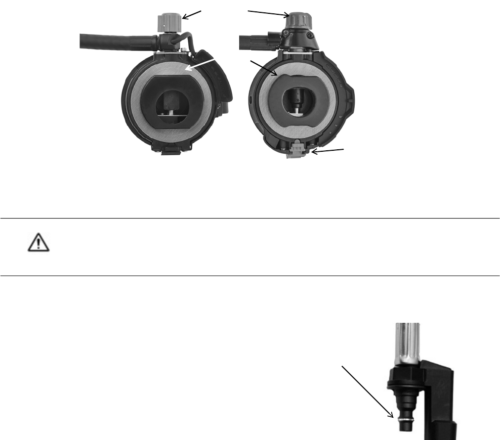
1 Verify that the purge valve (red knob) is not damaged and turns smoothly one-half turn from stop to stop. See
Figure 1-5.
2 Verify that the regulator gasket is not damaged and is in place around the outlet port of the regulator. See
Figure 1-5.
Figure 1-5 Inspecting the regulator
3 Inspect the HUD for damage. Verify that the rubber guard is in place and is not torn or damaged.
4 If the hose to the mask-mounted regulator is equipped with a quick-disconnect, inspect both the male and
female quick-disconnects. Pay special attention to the following:
a Inspect the operation of the locking sleeve on the female
quick-disconnect. If any damage is noted, remove it from
service and tag it for repair.
b Inspect the condition of the male quick-disconnect. Look for
signs of wear on the locking ridge as shown in Figure 1-6.
Figure 1-6 Inspecting the male quick-disconnect
CAUTION
Do not use tools to open or close the purge valve. Using tools to open or close the purge valve may result in
damage to the valve. Instead, open or close the valve using finger pressure only. Rotation of the purge valve
is limited to one-half turn.
Purge knob
Regulator
gasket
E-Z Flo+ (on AV-3000 HT)
E-Z Flo C5 (on Vision C5)
Auto air-saver
switch/Regulator
latch
Look for wear on
the locking ridge
INSPECTING THE RESPIRATOR
18 P/N 595360-01 Rev G 202004
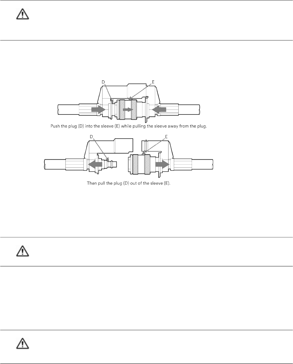
5 Verify that the quick-disconnect operates properly. Mask-mounted regulators equipped with a quick disconnect
use a pull-back sleeve coupling.
a While pushing the plug D into the socket, pull the locking sleeve E back toward the guard. The plug D will
separate. See Figure 1-7.
Figure 1-7 Testing the quick-disconnect
b To reconnect, align the HUD plug with the mating connector. A collar on the female coupling prevents
misalignment of the connectors. Verify that the HUD plug is properly aligned and fitted into the mating socket.
– Push plug D into the socket until the locking sleeve E pops forward.
– Test for proper engagement by tugging on the coupling.
6 If the regulator is not attached to the facepiece, proceed as follows:
a Align the regulator outlet port with the facepiece port. (The red purge valve on the regulator will be in the 12
o’clock position). Insert the regulator into the facepiece port.
b Rotate the regulator counterclockwise (as viewed from inside of facepiece) until the red purge valve knob is
on the left side of the facepiece. The lock tab of the E-Z Flo+ regulator or the latch on the E-Z Flo C5
regulator will lock into the facepiece retainer with a click. When the lock tab or latch is properly engaged, the
regulator will not rotate.
WARNING
If the coating is worn through and bare metal is showing on the male quick-disconnect locking ridge, remove
the regulator assembly from service and tag it for replacement. Use of a worn quick-disconnect locking ridge
may result in a malfunction, leading to a loss of breathing air, exposure to harmful substances, serious injury,
or death.
WARNING
Failure to properly check engagement of the coupling as described may lead to hose separation and loss of
breathing air, which may result in serious injury or death.
WARNING
Failure to properly check engagement of the regulator lock tab or latch to the facepiece as described may
result in rotation of the regulator. Any rotation of the regulator may cause the regulator to move out of its
proper position, which may cause loss of breathing air to the user and can lead to serious injury or death.

PERFORMING OPERATIONAL TESTING
P/N 595360-01 Rev G 202004 19
7 Verify that a full cylinder is properly installed in the backframe and that the reducer hose coupling is
hand-tightened to the cylinder valve outlet.
If you do not find any damage to the respirator, proceed to “Performing Operational Testing”.
Performing Operational Testing
Testing includes checking the basic operation of the respirator, followed by more thorough checks of the regulator,
HUD, sensor module lights, and batteries.
General Testing
1 Check that the mask-mounted regulator purge valve (red knob on regulator) is closed (the pointer on the knob
points up).
2 Fully depress the center of the air saver/donning switch on the top of the E-Z Flo+ regulator or firmly pull the
auto air-saver switch on the E-Z Flo C5 regulator latch and release.
3 Slowly open the cylinder valve by fully rotating the knob counterclockwise (approximately two-and-one-half
turns). Confirm that the following occur:
• The Vibralert alarm sounds and then stops.
• The HUD initializes.
– All lights turn on for 20 seconds before displaying the cylinder’s air supply level.
– If the low battery light remains lit or begins to flash, replace the batteries before proceeding. See
“Chapter 4: Replacing Batteries” on page 51.
• If the respirator is equipped with a Personal Alert Safety System (PASS) device, also known as a distress
alarm, you will hear three quick chirps when the cylinder valve is opened.
4 Check that the remote pressure gauge is operating properly and that its reading is within 10% of the value on the
cylinder pressure gauge.
5 Don the facepiece or hold the facepiece to your face to create a good seal.
a Inhale sharply to automatically start the flow of air. Breathe normally from the facepiece to ensure proper
operation.
b Remove the facepiece from your face. Confirm that air flows freely from the facepiece.
CAUTION
Do not use tools to tighten the hose couping, Over-tightening the hose coupling may damage the gasket
seal.
CAUTION
If any discrepancy or malfunction is noted during the inspection, do not use the respirator. Remove the
respirator from service and tag it for repair by authorized personnel.
WARNING
If any of the indicator alarms do not actuate as described, do not use the respirator, Remove the respirator
from service and tag it for repair by authorized personnel. Using a respirator with improperly operating
end-of-service indicators may result in serious injury or death.
INSPECTING THE RESPIRATOR
20 P/N 595360-01 Rev G 202004
6 Fully depress the center of the air saver/donning switch on the top of the E-Z Flo+ regulator or firmly pull the
auto air-saver switch on the E-Z Flo C5 regulator latch and release. The flow of air from the facepiece will stop.
7 Examine the complete respirator for air leaks. No air should leak from any part of the respirator.
.
Testing the Regulator
The regulator is equipped with a red purge valve (knob), which allows air to flow into the facepiece in an emergency
without breathing on the respirator. The purge control is also used to release residual air from the respirator after the
cylinder valve is turned off.
To check the purge valve
1 Rotate the purge valve one-half turn counterclockwise (turn the valve so that the pointer on the knob points
down). Air flows freely from the regulator.
2 Rotate the purge valve one-half turn clockwise to its fully closed position (the pointer on the knob points up). Air
flow from regulator stops.
3 Push in and rotate the cylinder valve knob clockwise to close the valve.
4 When the cylinder valve is fully closed, open the purge valve slightly to vent residual air pressure from system. As
the residual air pressure vents from the system, the remote pressure gauge needle will swing from full toward
empty.
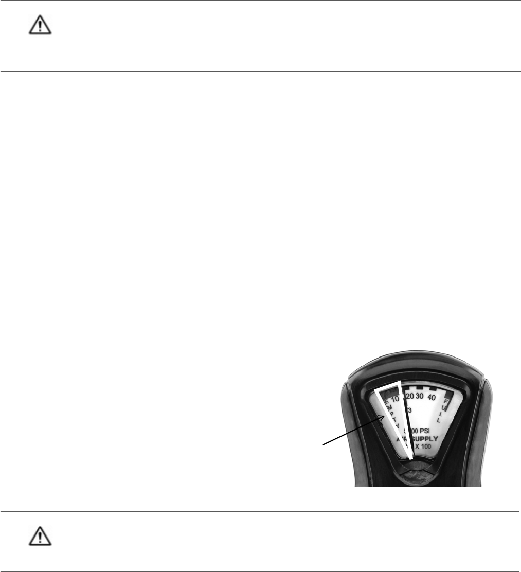
5 Observe the air supply indicator lights of the HUD and verify that they light properly in descending order.
6 When the gauge needle crosses the one-third mark but before it reaches the beginning of the red empty band,
close the purge valve. See Figure 1-8.
Confirm that the following occur:
• The Vibralert end-of-service indicator alarm
sounds (rapid clicking).
• The red light at the far left of the HUD flashes
at 10 times per second.
• On units equipped with a PASS device, the
gauge light on the remote pressure gauge is
solid red.
Figure 1-8 Remote pressure gauge
7 After verifying that all alarms are functioning, open the purge valve slightly to vent the remaining residual air
pressure from the system. All alarms (except the accessory electronic end-of-service time indicator) stop when
the system pressure drops to zero.
WARNING
An air leak from a respirator may indicate a potentially serious defect. An air leak may reduce the duration of
use and/or the time remaining after an end-of-service alarm actuates, or it may prevent an end-of-service
alarm from properly actuating. Using a respirator with an air leak may expose you to dangerous conditions,
which could lead to serious injury or death.
WARNING
If any of the end-of service indicators do not operate as described, do not use the respirator. Remove the
respirator from service and tag it for repair by authorized personnel. Use of a respirator with malfunctioning
end-of-service indicators may result in serious injury or death.
To test the HUD,
control the needle
between 1/3 and
empty.
PERFORMING OPERATIONAL TESTING
P/N 595360-01 Rev G 202004 21
8 When air flow stops completely, close the purge valve (the pointer on the knob points up).
9 Stop the electronic end-of-service time indicator by pressing the manual reset (yellow) button on the control
console twice and then twice again after the flashing green light sequence.
Testing the Heads-Up Display
The Heads-Up Display (HUD) provides a visual monitor of the air supply in the cylinder and valve assembly. The display
is fitted to the mask-mounted regulator and appears across the bottom of the user’s field of view through the
facepiece.
The HUD consists of four rectangular lights to represent the cylinder pressure at full and three-quarters, one-half, and
one-third full. A fifth red light indicates low battery.
The HUD operates as follows:
• When respirator use begins, the HUD will initialize and illuminate all lights for 20 seconds. Verify the operation of
all lights every time respirator use starts and with every regular operational inspection.
• After initialization, the rectangular indicator lights show the level of the air supply in the cylinder (see Figure 1-9):
• When the cylinder is more than three-quarters full, two green lights near the center of the display illuminate.
• When the cylinder is between one-half and three-quarters full, a single green light illuminates.
• When the cylinder is between one-third and one-half full, a yellow light flashes once per second.
• When the cylinder is less than one-third full, a red light at the far left of the display (the end-of-service time
indicator) flashes 10 times per second.
Figure 1-9 HUD Operation
1/3 - 1/2 full: Yellow light flashes slowly
Low battery: Red
1/2 - 3/4 full: 1 green light
> 3/4 full: 2 green lights
< 1/3 full: Red light flashes rapidly
E-Z Flo Regulator HUD on AV-3000 HT
1/3 - 1/2 full: Yellow light flashes slowly
Low battery: Red
1/2 - 3/4 full: 1 green light
> 3/4 full: 2 green lights
< 1/3 full: Red light flashes rapidly
E-Z Flo C5 Regulator HUD on Vision C5

INSPECTING THE RESPIRATOR
22 P/N 595360-01 Rev G 202004
• If the SCBA is equipped with a PASS device, the lights in the HUD will flash in an alternating pattern when the
distress alarm goes into pre-alarm mode. In addition, the color of the light illuminating the gauge dial will be the
same as the current cylinder level light showing in the HUD.
• The HUD has an automatic brightness control that dims the display in low-light situations and returns the display
to full brightness in bright-light situations.
• When the batteries require changing, the low-battery indicator at the right of the display lights for 20 seconds
and then begin to flash once per second.
When the low battery indicator is actuated, the batteries still have sufficient life to operate the HUD for a period
longer than the longest duration cylinder installed on the respirator. However, you must change the batteries im-
mediately upon termination of use of the respirator or before reentry into a hazardous atmosphere. See
“Chapter 4: Replacing Batteries” on page 51.
Table 1-1 summarizes the operation of the HUD lights:
WARNING
When an end-of-service indicator alarm actuates, leave the area requiring respiratory protection
immediately. Actuation of any end of service indicator alarm indicates that approximately 33% of full
pressure remains in the air supply cylinder (i.e., approximately 2/3 of the total air supply has been used) or
that there is a malfunction in the respirator. A delay in leaving the area after alarm actuation may result in
serious injury or death.
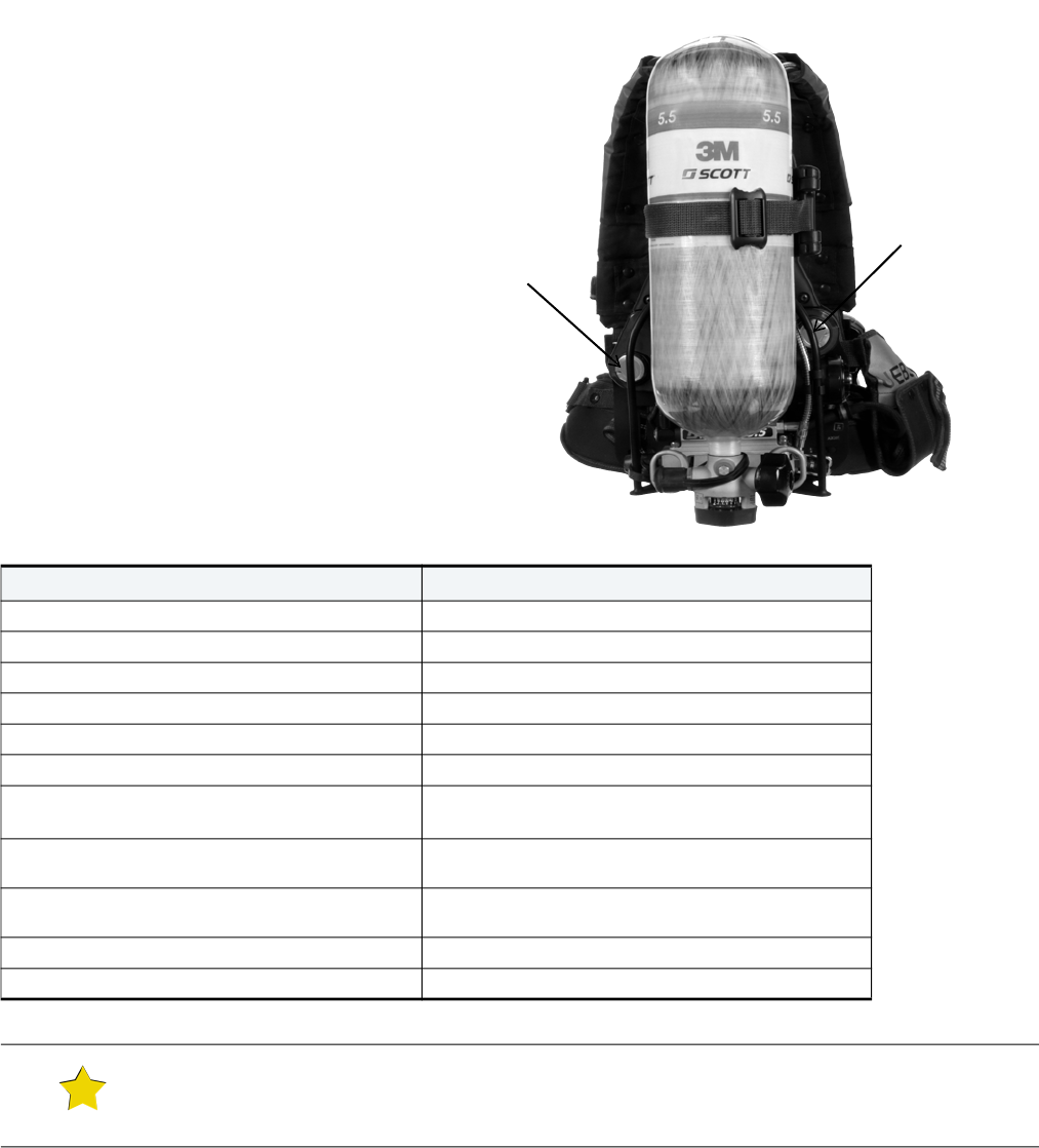
BEHAVIOR OF LIGHTS MEANING USER ACTION
2 glowing green lights Full Cylinder Continue using respirator
1 glowing green light 3/4 full Cylinder Continue using respirator
1 slowly flashing yellow light 1/2 full Cylinder Continue using respirator
1 rapidly flashing red light 1/3 full Cylinder Leave hazardous area immediately
Table 1-1 Heads-Up Display Indicator Lights
WARNING
If the HUD lights do not operate as described, do not use the respirator. Remove the respirator from service
and tag it for repair by authorized personnel. Use of a respirator with a malfunctioning HUD may result in
serious injury or death.
WARNING
If a respirator incorporating the HUD is used in an explosive or flammable atmosphere, regularly inspect the
respirator, including the HUD, as described and correct any damage found. Do not substitute any parts or
components. Use only the batteries specified in this manual. The failure to correct any damage, the
installation of incorrect batteries, or the substitution of any other parts or components may impair the
intrinsic safety of the unit and may result in serious injury or death.
PERFORMING OPERATIONAL TESTING
P/N 595360-01 Rev G 202004 23
Testing the Sensor Module Lights
When performing operational testing on
respirator units equipped with a PASS device
(distress alarm), verify that the sensor
module lights are operating properly.
Figure 1-10 shows the sensor modules on the
respirator, and Table 1-2 on page 23
describes how the lights behave for
particular actions or situations.
For more information about the sensor
module lights, see the manual for the Scott
Electronic Management System (SEMS) II.
Figure 1-10 Sensor modules
Table 1-2 Operation of Sensor Module Lights
ACTION OR SITUATION BEHAVIOR OF LIGHTS
Start Air-Pak SCBA (i.e., open cylinder valve) Bright light, then flashing green light
Normal operation Flashing green light
Air cylinder between 1/2 and 1/3 full Flashing yellow light (2 quick flashes) every second
Air cylinder less than 1/3 full (low air) Flashing yellow light (alternately)
Low battery while unit is on Flashing yellow light once every 2 seconds
Shut down Off
Press reset button on control console with unit off
(battery test)
Good battery: Bright light, then flashing green light
Low battery: Bright light, then flashing red light
Press manual alarm button on control console with
unit off
Flashing red light (simultaneously)
Press reset button on control console during full
alarm
Flashing green light
PASS pre-alarm Flashing red light (alternately)
PASS full alarm Flashing red light (simultaneously)
TIP
The yellow light is a combination of the red, green, and white lights on the sensor module. At close range, the
individual lights may be visible.
Sensor Module
Sensor Module

INSPECTING THE RESPIRATOR
24 P/N 595360-01 Rev G 202004
Testing the Batteries
On respirators equipped with a distress alarm, the battery condition can be tested manually as follows:
1 Make sure the distress alarm is off (i.e., the cylinder valve is closed, and no sensor module lights are flashing).
2 Press and hold the manual reset (yellow) button on the console. Observe the final light color (green or red) in the
sequence to determine the battery status.
• Green lights on the control console and sensor module indicate that sufficient battery power remains.
• Red lights on the control console and sensor module indicate that the batteries are low and must be replaced
before the respirator is used again. 3M recommends replacing all batteries before the respirator is used again.
See “Chapter 4: Replacing Batteries” on page 51.
CAUTION
Do not use tools to close the cylinder valve. Over-tightening the cylinder valve may cause damage that
could result in air leaking from the cylinder.
P/N 595360-01 Rev G 202004 25
CHAPTER 2
SOFT GOODS ASSEMBLY & DISASSEMBLY
This chapter provides instructions for detaching the soft goods (shoulder harness, waist pad, and straps) from the
backframe (in preparation for laundering or replacement) and reattaching them to the backframe.
• “Detaching the Shoulder Harness and Waist Pad” on page 25
• “Attaching the Shoulder Harness and Waist Pad” on page 32
Detaching the Shoulder Harness and Waist Pad
You can detach the shoulder harness and waist pad from the backframe without any tools.
To detach the shoulder harness from the backframe
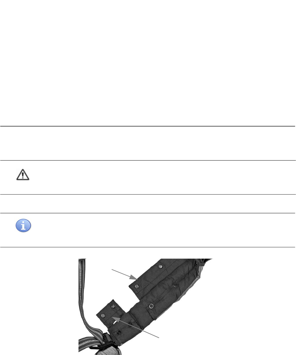
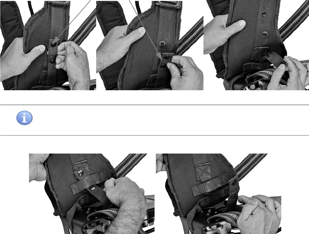
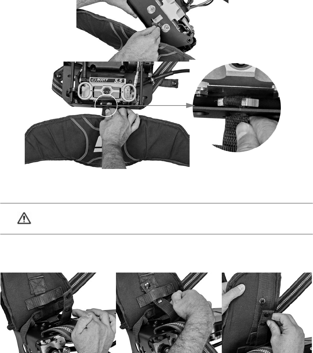
1 Open the lower and upper flaps of both shoulder pads by unfastening the snap closures. See Figure 2-1.
Figure 2-1 Opening the upper and lower shoulder pad flaps
CAUTION
Before detaching the shoulder harness or waist pad, be sure to shut off the respirator and remove the
breathing air cylinder as outlined in the operating and maintenance instructions provided with your 3M Scott
Air-Pak SCBA.
NOTE
If you have installed the 3M Scott Air-Pak X3 Pro SCBA chest strap accessory, uninstall it as directed in
Chest Strap Accessory for the 3M Scott Air-Pak X3 Pro SCBA: Installation and Use Instructions (P/N
595366-01) before detaching the shoulder harness from the backframe.
Lower flap
Upper flap
P/N 595360-01
202004
Rev G
SOFT GOODS ASSEMBLY & DISASSEMBLY
26 P/N 595360-01 Rev G 202004
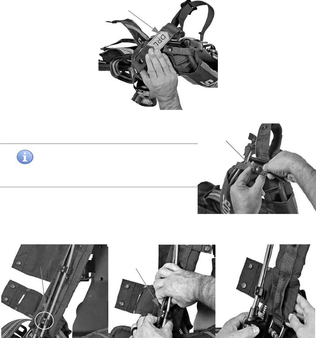
2 Unsnap the drag rescue loop from the shoulder pad. See Figure 2-2.
Figure 2-2 Unsnapping the drag rescue loop from the shoulder pad
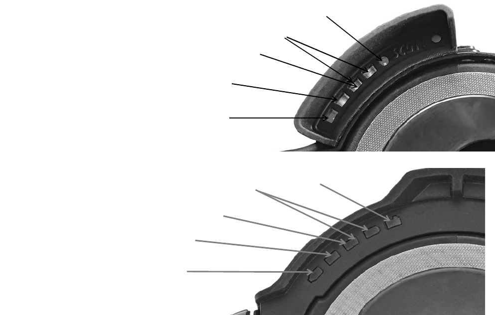
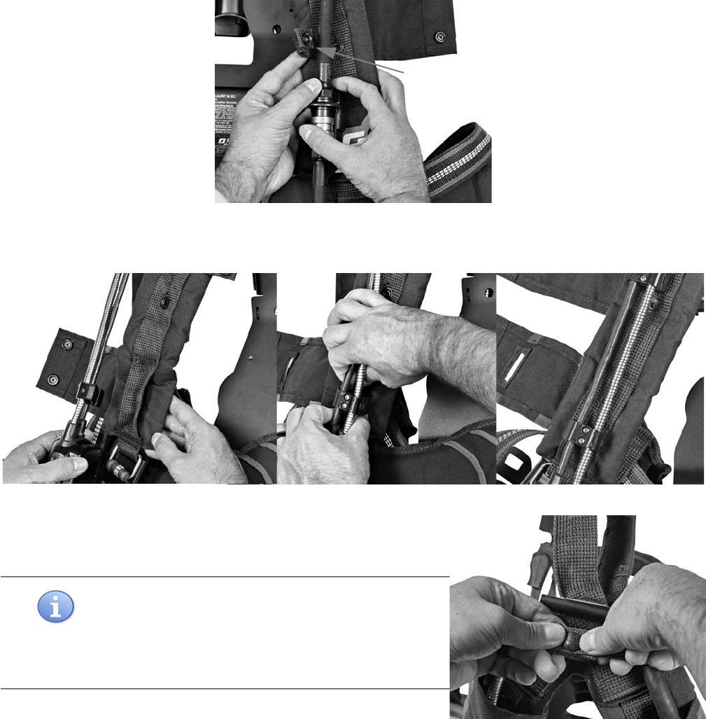
3 At the top of the shoulder harness, unsnap the straps securing the
cable, gaugeline, and regulator hose. See Figure 2-3.
4 Move the cable, gaugeline, and regulator hose to their respective
sides.
Figure 2-3 Unsnapping the top strap securing the cable, gaugeline, and regulator hose
5 Remove the lower cable routing clamp from the shoulder pad webbing by folding the edges of the webbing
together to form a “V” and sliding the edges through the clamp opening. See Figure 2-4.
Figure 2-4 Removing the lower cable routing clamp
NOTE
The snap at the top of the shoulder harness is a directional
snap fastener. To open (unsnap), lift the edge with the dot.
Do not use a tool or excessive force to engage or
disengage the snaps.
Drag rescue loop
Top snap
Lower cable
routing clamp
Fold the
webbing to form
a “V”
DETACHING THE SHOULDER HARNESS AND WAIST PAD
P/N 595360-01 Rev G 202004 27
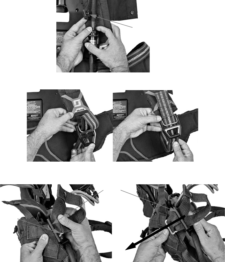
6 Unsnap the 2 regulator hose retaining straps. See Figure 2-5.
Figure 2-5 Unsnapping the regulator hose retaining strap
7 Detach the waist-to-shoulder straps from the buckles at the bottom of the shoulder harness. See Figure 2-6.
Figure 2-6 Detaching the waist-to-shoulder straps
8 Flatten the upper metal slide at the base of the drag rescue loop and pull the slide through the upper slot of the
clevis (metal connector at the top of the backframe). See Figure 2-7.
Figure 2-7 Pulling the upper metal slide through the clevis
Lower regulator
hose retaining strap
Upper
metal
slide
Clevis
Pull the metal
slide through the
clevis
SOFT GOODS ASSEMBLY & DISASSEMBLY
28 P/N 595360-01 Rev G 202004
9 Position the drag rescue loop so that its snaps line up with the center of the upper slot of the clevis. Carefully, pull
the loop through the slot, taking care not to damage the snaps. See Figure 2-8.
Figure 2-8 Pulling the drag rescue loop through the upper slot of the clevis
10 Pull the lower metal slide and webbing through the lower slot of the clevis to complete the removal of the
shoulder harness from the backframe. See Figure 2-9.
Figure 2-9 Pulling the lower metal slide through the lower slot of the clevis
TIP
Lifting the shoulder pads to align the upper and lower metal slides with the clevis slots helps them pass
through the slots more easily.
Pull the loop
through the
slot
Pull the metal
slide through
the slot

DETACHING THE SHOULDER HARNESS AND WAIST PAD
P/N 595360-01 Rev G 202004 29
To detach the waist pad from the backframe
The waist pad is attached to the backframe by the waist pad retaining strap and webbing attached to a metal I-bar.
To facilitate detachment of the waist pad from the backframe, you will first need to remove the waist belt and the
Universal EBSS (UEBSS) or dual EBSS pouch
1
.
1 Remove the waist belt from the waist pad.
a Detach the mask-mounted regulator from the regulator holder (if attached) by engaging the lock tab of the
E-Z Flo+ regulator or the latch on E-Z Flo C5 regulator until it releases from the holder.
b Unbuckle the waist belt by pressing the button in the center of the metal buckle. Remove each end of the belt
from the buckles on each side of the waist pad. Set the waist belt aside.
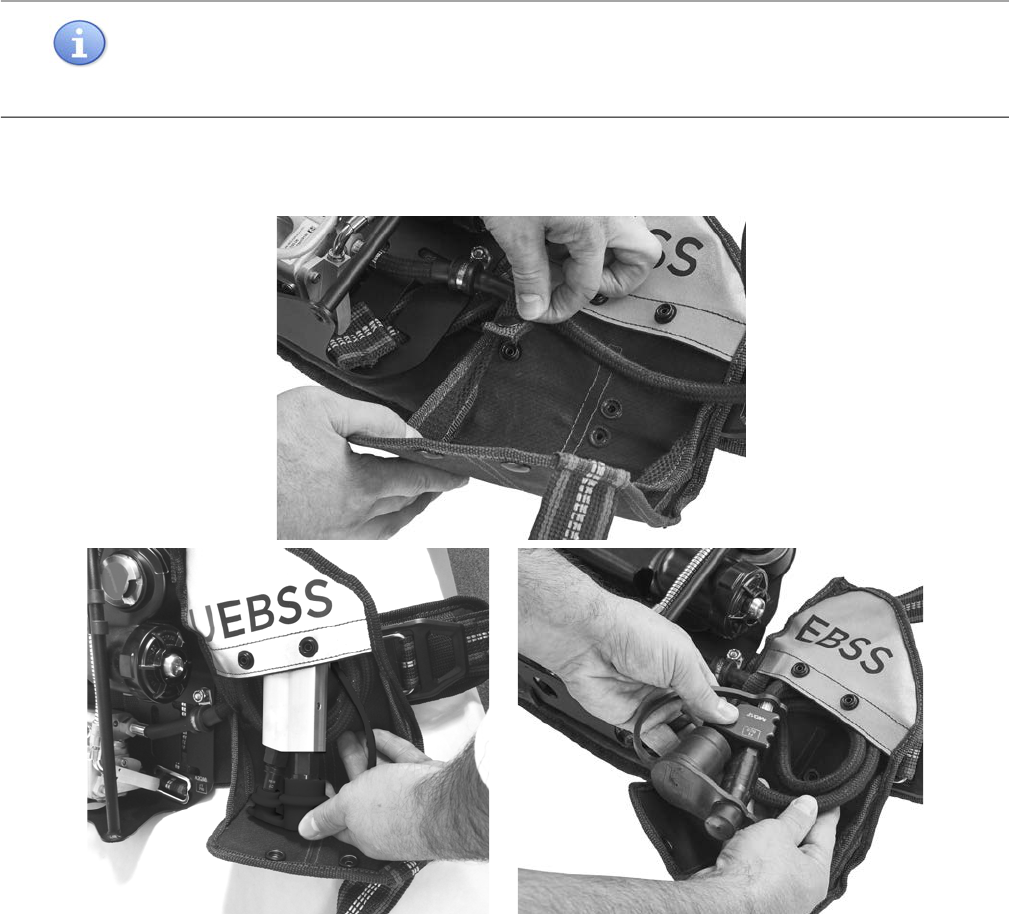
2 Remove the UEBSS or dual EBSS pouch (if installed) from the waist pad. See Figure 2-10.
a Pull the waist-to-shoulder strap through the loop on the UEBSS or dual EBSS pouch (see picture A).
b Unsnap the following fasteners:
– on the back of the pouch that connect it to the waist pad (see picture B)
– on the flap that closes the pouch (see picture C)
– on the strap securing the UEBSS or dual EBSS hose (see picture D)
c Remove the UEBSS or dual EBSS hose from the pouch and set the pouch aside.
Figure 2-10 Removing the UEBSS or dual EBSS pouch from the waist pad by A) pulling the waist-to-shoulder strap through the loop on the
pouch and unsnapping the fasteners B) on the back of the pouch, C) on the pouch flap, and D) on the strap securing the UEBSS or dual EBSS hose.
1. UEBSS is compatible with 3M Scott Air-Pak SCBAs manufactured in accordance with the NFPA 1981, 2018 edition
standard. Dual EBSS is compatible with 3M Scott Air-Pak SCBAs manufactured prior to
the NFPA 1981, 2018 edition
standard.
A
Pull the waist-to-shoulder
strap through the loop
B
Pouch flap
C
Strap securing EBSS hose
Strap securing UEBSS or dual EBSS hose
D
SOFT GOODS ASSEMBLY & DISASSEMBLY
30 P/N 595360-01 Rev G 202004
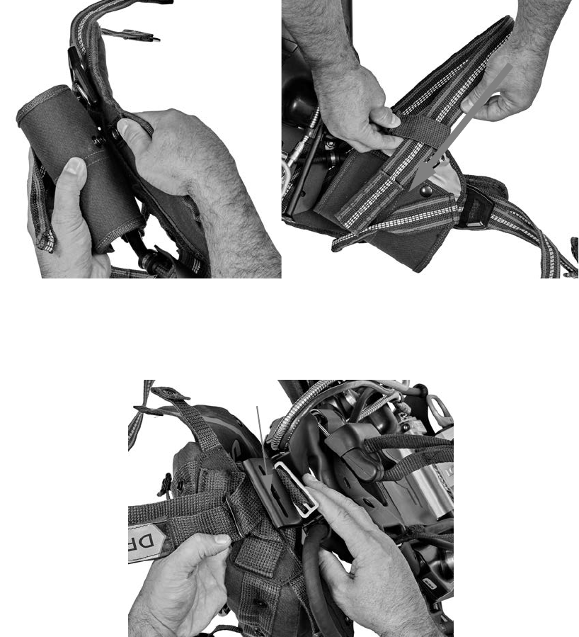
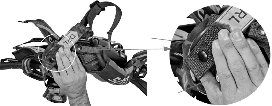
3 Unsnap the waist pad retaining strap using either of the following methods:
• Method 1: Unsnap both ends to fully remove the waist pad retaining strap from the waist pad.
i Locate the two snaps securing the ends of the waist pad retaining strap to the waist pad.
ii Insert one or more fingers between the two snaps at each end and pull up to unsnap. See Figure 2-11.
Figure 2-11 Unsnapping one end of the waist pad retaining strap
iii Slide each end of the waist pad retaining strap through the sewn loop of the waist pad. See Figure 2-12.
Figure 2-12 Sliding the waist pad retaining strap through the waist pad loop
iv Fold the waist pad away from the backframe.
NOTE
The snaps attaching the waist pad retaining strap to the waist pad are directional snap fasteners. To open
(unsnap), lift the edge with the dot. Do not use a tool or excessive force to engage or disengage the snaps.
Waist pad retaining strap
DETACHING THE SHOULDER HARNESS AND WAIST PAD
P/N 595360-01 Rev G 202004 31
v Pull the waist pad retaining strap through the opening in the backframe and set aside. See Figure 2-13.
Figure 2-13 Pulling the waist pad retaining strap through the backframe opening
• Method 2: Unsnap one end of the waist pad retaining strap so that it remains attached to the waist pad.
i Locate the two snaps securing either end of the waist pad retaining strap to the waist pad.
ii Insert one or more fingers between the two snaps and pull up to unsnap. See Figure 2-11. Leave the other
end of the waist pad retaining strap attached to the waist pad.
iii Slide the unfastened end of the waist pad retaining strap through the sewn loop of the waist pad. See
Figure 2-12.
iv Continue sliding the unfastened end of the waist pad retaining strap through the backframe openings and
the second sewn loop of the waist pad. See Figure 2-13. The waist pad retaining strap is now removed
from the backframe but still attached to the waist pad at one end.
v Fold the waist pad away from the backframe.
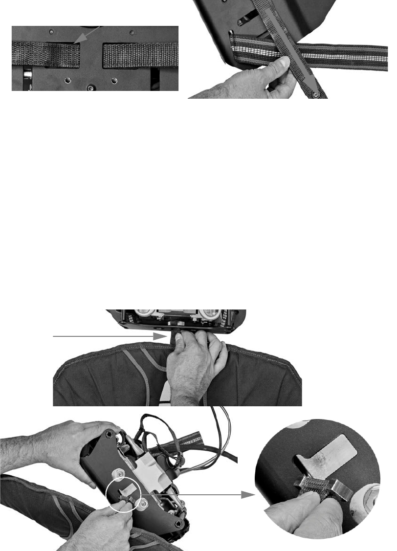
4 At the bottom of the backframe, locate the webbing attaching the waist pad to the backframe. Turn the webbing
90 degrees clockwise or counterclockwise to align the metal I-bar with the backframe opening and pull it out.
See pictures A and B in Figure 2-14.
Figure 2-14 A) Turning the webbing 90 degrees to align the metal I-bar. B) Pulling out the I-bar.
Backframe opening for the waist pad
retaining strap
Pull the waist pad
retaining strap
through the
backframe
opening
Webbing
attaching
waist pad to
backframe
B
Pull the I-bar through
the backframe opening
Turn the webbing 90 degrees
clockwise or counterclockwise
to align the I-bar with the
opening
A
A
SOFT GOODS ASSEMBLY & DISASSEMBLY
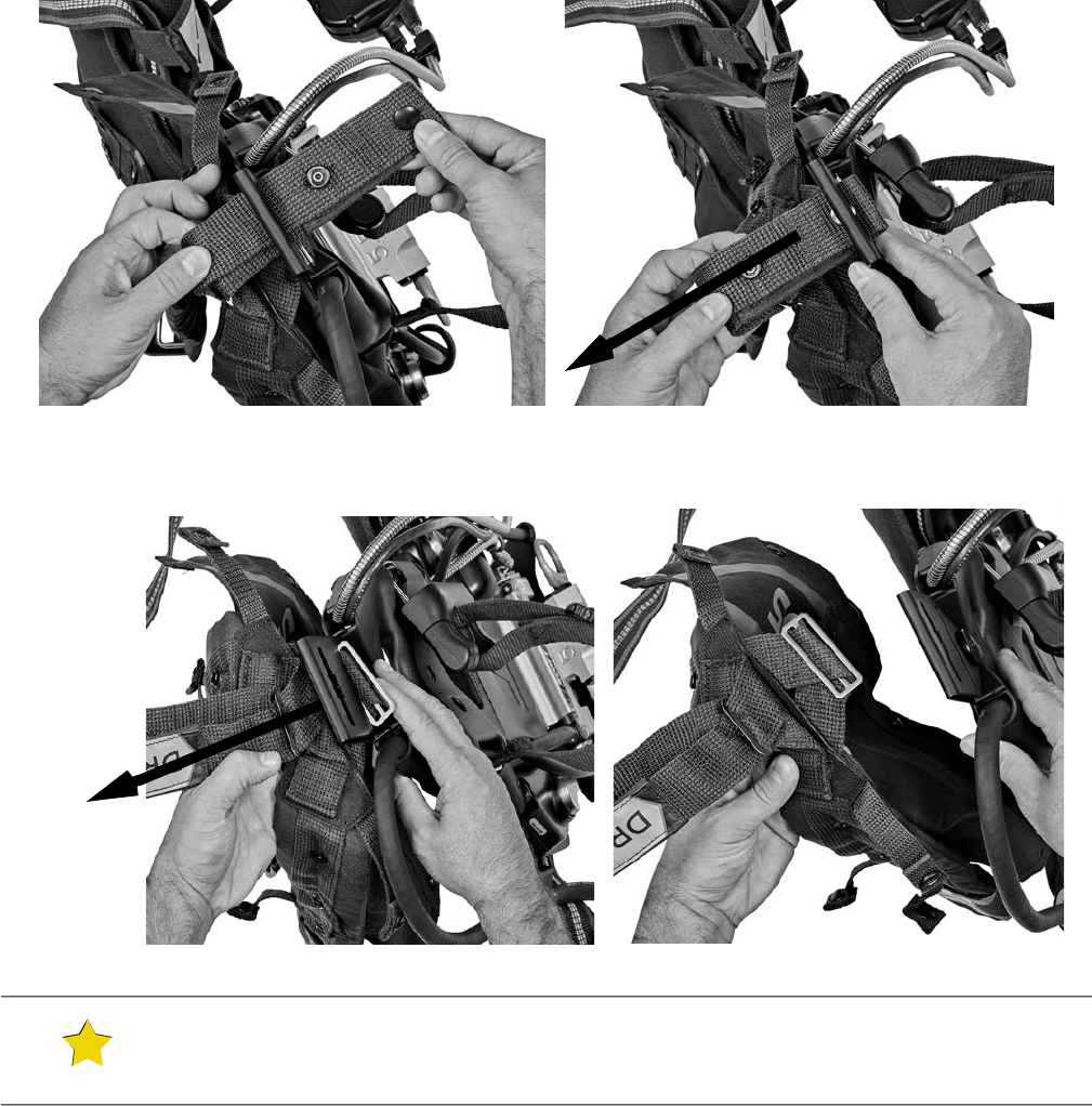
32 P/N 595360-01 Rev G 202004
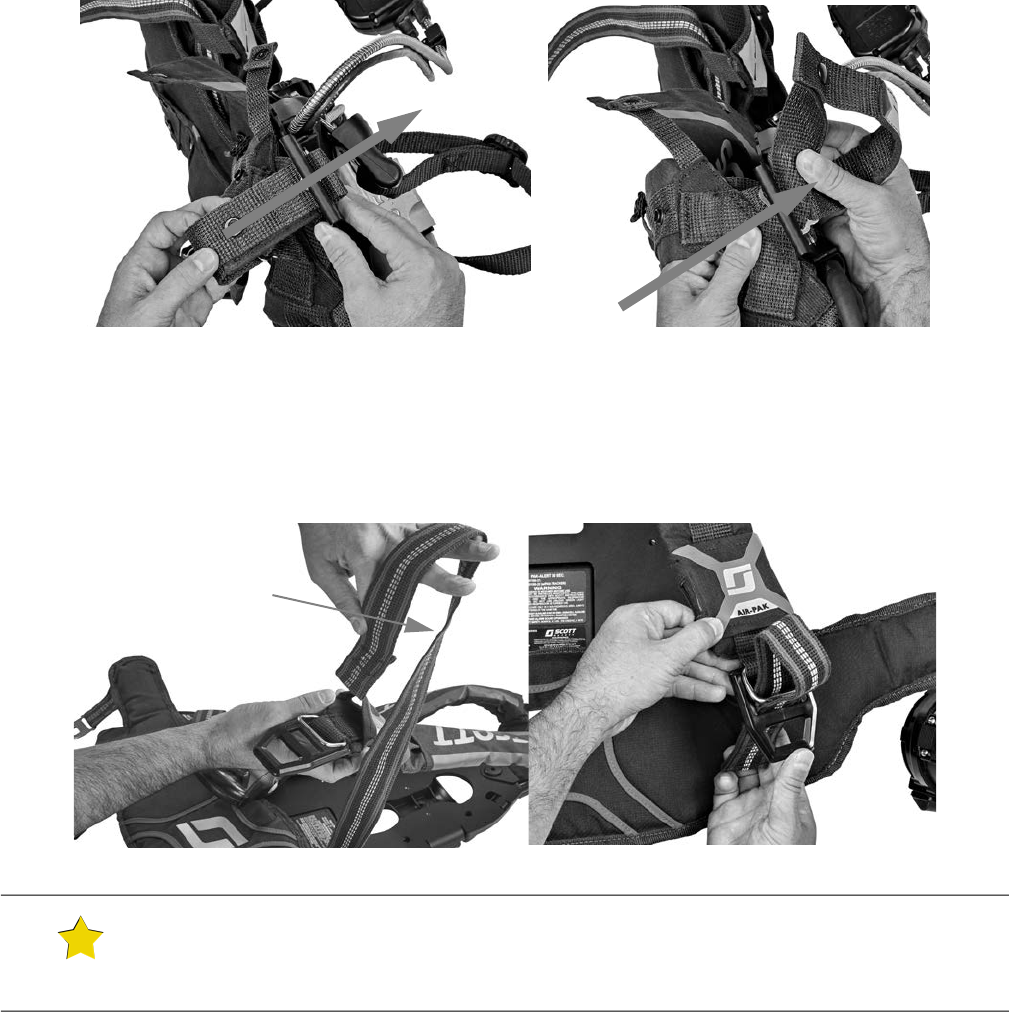
5 Remove the waist-to-shoulder straps from each side of the backframe and set aside.
a From the rear of the backframe, locate the tri-slide securing the waist-to-shoulder straps to the backframe.
b Pull the tri-slide away from the backframe until the opposite end of the waist-to-shoulder strap can be fed
through the backframe slot. See Figure 2-15.
c Repeat for the other side.
Figure 2-15 Removing the waist-to-shoulder straps from the backframe
Attaching the Shoulder Harness and Waist Pad
To attach the waist pad to the backframe
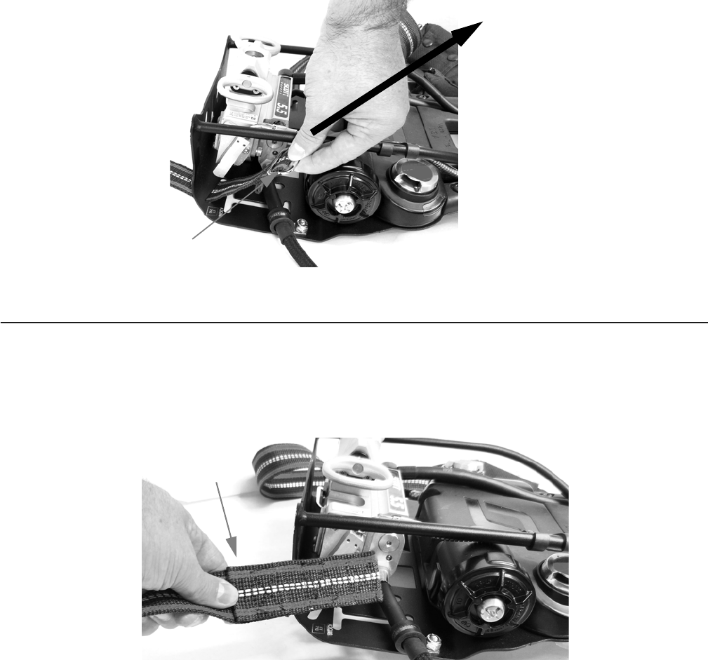
1 Attach the waist-to-shoulder straps to the backframe.
a Grasp the folded end of a waist-to-shoulder strap. See Figure 2-16.
Figure 2-16 Grasping the folded end of the waist-to-shoulder strap.
b With the sewn side facing up, feed the waist-to-shoulder strap through the backframe slot (starting front to
back) until the tri-slide is flush against the backframe. See Figure 2-17.
Tri-slide
Pull tri-slide away from
backframe
Folded end of strap,
sewn side facing up
ATTACHING THE SHOULDER HARNESS AND WAIST PAD
P/N 595360-01 Rev G 202004 33
Figure 2-17 Feeding the waist-to-shoulder strap through the backframe slots.
c Tug on the waist-to-shoulder strap to ensure a secure attachment.
d Repeat steps a-c for the other waist-to-shoulder strap.
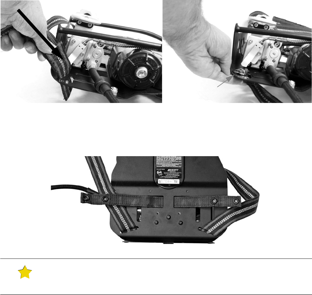
2 Feed one end of the waist pad retaining strap through the backframe opening with the fasteners facing up. See
Figure 2-18.
Figure 2-18 Installing the waist pad retaining strap to the backframe
TIP
Figure 2-18
shows installation of the waist pad retaining strap after unsnapping both ends from the waist
pad. You may have chosen to unsnap only 1 end of the waist pad retaining strap, leaving the other end
attached to the waist pad.
Feed strap through
backframe slot
Tri-slide is flush against the
backframe
SOFT GOODS ASSEMBLY & DISASSEMBLY
34 P/N 595360-01 Rev G 202004
3 On the waist pad, locate the webbing attached to the metal I-bar.
a Insert the metal I-bar into the slot at the base of the backframe and rotate it 90 degrees clockwise or
counterclockwise to “lock” it in place. See Figure 2-19 for proper orientation of the I-bar.
Figure 2-19 Inserting the metal I-bar to attach the waist pad to the backframe
b Ensure that the webbing sits within the slot. Tug on the webbing to make sure it is securely attached to the
backframe.
4 Fold the waist pad under the backframe until it is flush.
5 Thread the ends of the waist pad retaining strap through the sewn loops on the waist pad and snap them in place
on the waist pad. (If you chose to unsnap only 1 end of the waist pad retaining strap, you will need to thread only
the unsnapped end through the waist pad loops.) See Figure 2-20.
Figure 2-20 Threading the waist pad retaining strap through the waist pad loop and snapping it into place
CAUTION
Ensure that the I-bar is oriented properly within the backframe. Improper orientation of the I-bar within the
backframe may negatively impact respirator performance.
Rotate the I-bar 90 degrees clockwise or
counterclockwise to lock it in place. Orient it
as shown above.
ATTACHING THE SHOULDER HARNESS AND WAIST PAD
P/N 595360-01 Rev G 202004 35
6 Attach the UEBSS or dual EBSS pouch to the waist pad.
a Secure the UEBSS or dual EBSS hose into place by snapping the retaining strap. Coil the hose and fit it into the
pouch. See Figure 2-21.
Figure 2-21 A) Securing the UEBSS or dual EBSS hose. Coiling the hose and fitting the hose into the pouch for B) UEBSS and C) dual EBSS.
b Snap the fasteners on the flap to close the pouch.
c Locate the strap on the back of the pouch and slide it under the waist pad webbing and fasten the snaps. See
picture A in Figure 2-22.
d Feed the waist-to-shoulder strap through the loop in the UEBSS or dual EBSS pouch. See picture B in
Figure 2-22.
NOTE
The snaps attaching the waist pad retaining strap and waist pad are directional snap fasteners. To snap
closed, align the two sides of the fastener and press from the end opposite the dot toward the end with the
dot until you hear a “snap.” Do not use a tool or excessive force to engage or disengage the snaps.
A
B
C
SOFT GOODS ASSEMBLY & DISASSEMBLY
36 P/N 595360-01 Rev G 202004
Figure 2-22 A) Fastening the snaps attaching the UEBSS or dual EBSS pouch to the waist pad. B) Attaching the waist-to-shoulder straps.
To attach the shoulder harness to the backframe
1 Pass the lower metal slide and webbing through the lower slot of the clevis (see Figure 2-23). Lift the shoulder
pads and orient the metal slide at an angle to help it pass through the slot.
Figure 2-23 Passing the lower metal slide through the lower slot of the clevis
2 Pass the drag rescue loop through the upper slot of the clevis.
a Align the snaps on the loop with the center of the slot and carefully pull the loop through the slot, taking care
not to damage the snaps. See picture A in Figure 2-24.
b Flatten the metal slide and pass it through the upper slot. Lift the shoulder pads to help the slide pass through
the slot. See picture B in Figure 2-24.
A B
Feed strap through
loop on UEBSS or dual
EBSS pouch
Clevis
ATTACHING THE SHOULDER HARNESS AND WAIST PAD
P/N 595360-01 Rev G 202004 37
Figure 2-24 Passing the drag rescue loop through the upper slot of the clevis: A) Lining up the snaps. B) Passing the metal slide through the
clevis.
3 Attach the shoulder harness to the waist pad.
a Twist the waist-to-shoulder strap 1/2 turn outward (away from the backframe). See picture A in Figure 2-25.
b Thread the twisted strap through the buckle on the shoulder harness. See picture B in Figure 2-25.
c Repeat steps a and b for the other waist-to-shoulder strap.
Figure 2-25 Attaching the waist-to-shoulder straps: A) Twisting the strap 1/2 turn. B) Threading the strap through the buckle.
4 Secure the regulator hose to the shoulder pad by fastening the 2 regulator hose retaining straps. See Figure 2-26.
TIP
By twisting the waist-to-shoulder straps, you ensure that the sewn sides of straps rest against your body
when you don the respirator. Your thumbs will “catch” the folded ends of the waist-to-shoulder straps when
you adjust them during the respirator donning process.
A
B
Pull drag
rescue loop
through slot
Pass metal
slide through
slot
A B
Twist the strap 1/2
turn outward
SOFT GOODS ASSEMBLY & DISASSEMBLY
38 P/N 595360-01 Rev G 202004
Figure 2-26 Securing the regulator hose
5 Attach the lower cable routing clamp to the shoulder pad webbing by folding the edges of the webbing together
to form a “V” and sliding the edges into the clamp opening. See Figure 2-27.
Figure 2-27 Attaching the lower cable routing clamp
6 Position the straps at top of the shoulder harness over the cable,
gaugeline, and regulator hose. Snap the fastener closed. See
Figure 2-28.
Figure 2-28 Securing the cables and hose
7 Snap the fastener on the drag rescue loop together and then snap the loop to the shoulder pad. See Figure 2-29.
Ensure that the cable and gaugeline are positioned on opposite sides of the snap.
NOTE
The snaps at the top of the shoulder harness are directional
snap fasteners. To snap closed, align the two sides of the
fastener and press from the end opposite the dot toward the
end with the dot until you hear a “snap.” Do not use a tool or
excessive force to engage or disengage the snaps.
Lower regulator
hose retaining
strap
ATTACHING THE SHOULDER HARNESS AND WAIST PAD
P/N 595360-01 Rev G 202004 39
Figure 2-29 Securing the drag rescue loop
8 Wrap the upper and lower flaps around the shoulder pads and snap them closed. Ensure that the regulator hose is
not secured under the lower flap.
The drag rescue loop
snaps between the cable
and gaugeline on the
shoulder pad.
Cable
Gaugeline
SOFT GOODS ASSEMBLY & DISASSEMBLY
40 P/N 595360-01 Rev G 202004

P/N 595360-01 Rev G 202004 41
CHAPTER 3
CLEANING & STORING THE RESPIRATOR
This chapter provides instructions for cleaning and storing the 3M Scott Air-Pak X3 Pro SCBA. Detailed instructions
for cleaning the facepiece, mask-mounted regulator, shoulder harness, and waist pad are also provided.
• “Before You Begin” on page 41
• “Cleaning the Respirator” on page 42
• “Cleaning the Facepiece” on page 42
• “Cleaning the Mask-Mounted Regulator” on page 44
• “Cleaning the Shoulder Harness and Waist Pad” on page 47
• “Storing the Respirator” on page 50
Before You Begin
After using the respirator, clean it according to these instructions and perform a regular operational inspection as
outlined in “Chapter 1: Inspecting the Respirator” on page 11. If you find any damage, remove the respirator from
service and tag it for repair by authorized personnel.
Prior to handling or using any of the cleaning agents mentioned in this instruction, please consult the manufacturer’s
Safety Data Sheet (SDS) for precautions and important instructions.
WARNING
Do not attempt any repair or alteration of this respirator beyond the scope of this instruction without proper
training. Training is required for further service or repair of this respirator. Failure to properly service or have
this respirator properly repaired by a certified technician may result in serious injury or death.
WARNING
Keep all sanitizing or disinfecting cleaners out of the reach of children. Use the cleaner only in the manner
consistent with the product labeling and use instructions. Follow all applicable instructions, including but not
limited to those found on the Material Safety Data Sheet (MSDS) provided with any sanitizing or disinfecting
cleaners
. Improper use or handling of these products may result in serious injury or death.
WARNING
If you suspect the respirator has been contaminated by a hazardous substance, you must identify and
properly remove the contaminant or replace the contaminated component(s) prior to using the respirator
again. Dispose of contaminants or contaminated component(s) in accordance with applicable regulatory
requirements. Failure to properly clean a contaminated respirator or properly handle contaminants may
result in serious injury or death.
CAUTION
Certain cleaning and disinfecting agents, such as quaternary ammonium compounds (ammonium chlorides)
may cause damage, deterioration, or accelerated aging to parts of the respirator. Use only the
recommended cleaning and disinfecting agents.
P/N 595360-01
202004
Rev G

CLEANING & STORING THE RESPIRATOR
42 P/N 595360-01 Rev G 202004
Cleaning the Respirator
Because the cleaning procedures involve the use of liquids, respirators stored or used at cold temperatures must be
warmed before cleaning. Respirators being used at cold temperatures after cleaning must be completely dry.
To clean the respirator
1 Using a damp sponge, wipe any accumulated dirt from the exterior of the respirator.
2 Clean the facepiece and mask-mounted regulator as described in “Cleaning the Facepiece” on page 42 and
“Cleaning the Mask-Mounted Regulator” on page 44.
You can remove the shoulder harness and waist pad assemblies for decontamination or laundering. See
“Chapter 2: Soft Goods Assembly & Disassembly” on page 25 and “Cleaning the Shoulder Harness and Waist Pad” on
page 47.
Cleaning the Facepiece
You will need the following supplies:
• 3M-approved sanitizing or disinfecting cleaner.
If an approved disinfectant is not available, you can disinfect the facepiece using one of the following solutions:
• Hypochlorite solution (50 ppm of chlorine) made by adding approximately one milliliter (1 mL) of laundry
bleach to one liter (1 L) of water at 110° F / 43° C
-OR-
• Aqueous solution of iodine (50 ppm iodine) made by adding approximately 0.8 mL of tincture of iodine (6-8
grams ammonium and/or potassium iodide/100 cc of 45% alcohol) to 1 L of water at 110° F / 43° C
• Spray bottle (for the sanitizing or disinfecting cleaner)
• Drinking (potable) water, either from a faucet or in a spray bottle
• Clean, lint-free cloth
• (Optional) Lubricant-free, dry breathing air, maximum 30 psig, for drying the facepiece
NOTE
The light sensor for the HUD brightness control is located on the front of the remote gauge housing. Be sure
to clean the front of the remote gauge housing to enable proper functioning of the sensor.
CAUTION
Remove any 3M Scott Sight In-Mask Display (IMD) components prior to cleaning the AV-3000 HT
facepiece. IMD components are factory-sealed to protect the optics and electronics from dirt and moisture.
Clean these components when necessary using a cloth dampened with a solution of mild detergent and
water. If the IMD and/or the mask-mounted thermal imaging camera (TIC) assembly has been exposed to
potentially hazardous materials, decontaminate in accordance with established procedures.
CAUTION
When using cleaning products, follow all of the manufacturer’s instructions. Improper use or handling of
these products may result in damage to the facepiece.

CLEANING THE RESPIRATOR
P/N 595360-01 Rev G 202004 43
To clean the facepiece
1 Remove the mask-mounted regulator from the facepiece.
2 If the facepiece is heavily soiled, you want to first wash the facepiece with a solution of mild soap or detergent in
warm water (110° F / 43° C maximum).
• Using a spray bottle, apply a solution of mild soap or detergent in warm water (110° F / 43° C maximum) to the
soiled surfaces. Rinse the facepiece with drinking water either from a faucet or in a spray bottle.
-OR-
• Clean the facepiece using 3M-approved cleaning wipes.
3 To sanitize or disinfect the facepiece, use a spray bottle to apply the recommended sanitizing or disinfecting
cleaner to all surfaces of facepiece. Be sure to cover all surfaces completely with the cleaning solution.
4 Set the facepiece aside for the required contact time prior to rinsing. The hypochlorite solution and the aqueous
solution of iodine require a 2-minute contact time.
5 Rinse the facepiece with drinking water either from a faucet or in a spray bottle.
6 Shake excess water off the facepiece and dry it with a clean, lint-free cloth or gently blow dry with clean, dry
breathing air of 30 psig or less pressure. Do not use shop air or any other air containing lubricants or moisture.
CAUTION
When cleaning the facepiece, do not use the following cleaning products:
• Abrasive cleaners
• Bleach stronger than a 3% solution in water
• Solvents such as acetone, paint and lacquer thinner, benzene, or dry-cleaning fluid.
In addition, do not do the following:
• “Dunk and slosh”
• Polish with paper towels as most paper contains abrasives
• Autoclave or wash in an unapproved automatic washer
• Use a vapor degreaser/polisher
NOTE
A nose cup is designed to be an integral part of the facepiece and does not need to be disassembled for
cleaning unless the facepiece is heavily soiled.
NOTE
The Kevlar head harnesses are made of porous material. The recommended cleaner may not be effective on
porous material.

CLEANING & STORING THE RESPIRATOR
44 P/N 595360-01 Rev G 202004
Cleaning the Mask-Mounted Regulator
You will need the following supplies:
• Sanitizing or disinfecting cleaner. 3M recommends a properly diluted hypochlorite solution or aqueous solution
of iodine:
– Hypochlorite solution (50 ppm of chlorine) made by adding approximately one milliliter (1 mL) of laundry
bleach to one liter (1 L) of water at 110° F / 43° C
-OR-
– Aqueous solution of iodine (50 ppm iodine) made by adding approximately 0.8 mL of tincture of iodine (6-8
grams ammonium and/or potassium iodide/100 cc of 45% alcohol) to 1 L of water at 110° F / 43° C
• Spray bottle (for the sanitizing or disinfecting cleaner)
• Sponge or soft cloth
• Drinking (potable) water, either from a faucet or in a spray bottle
• (Optional) Lubricant-free, dry breathing air, maximum 30 psig, for drying the regulator
To clean the mask-mounted regulator
1 Remove the mask-mounted regulator from the facepiece by engaging the lock tab of the E-Z Flo+ regulator or
the latch on E-Z Flo C5 regulator.
2 Using a sponge or soft cloth and the recommended sanitizing or disinfecting cleaner, wipe the external surfaces
of the regulator.
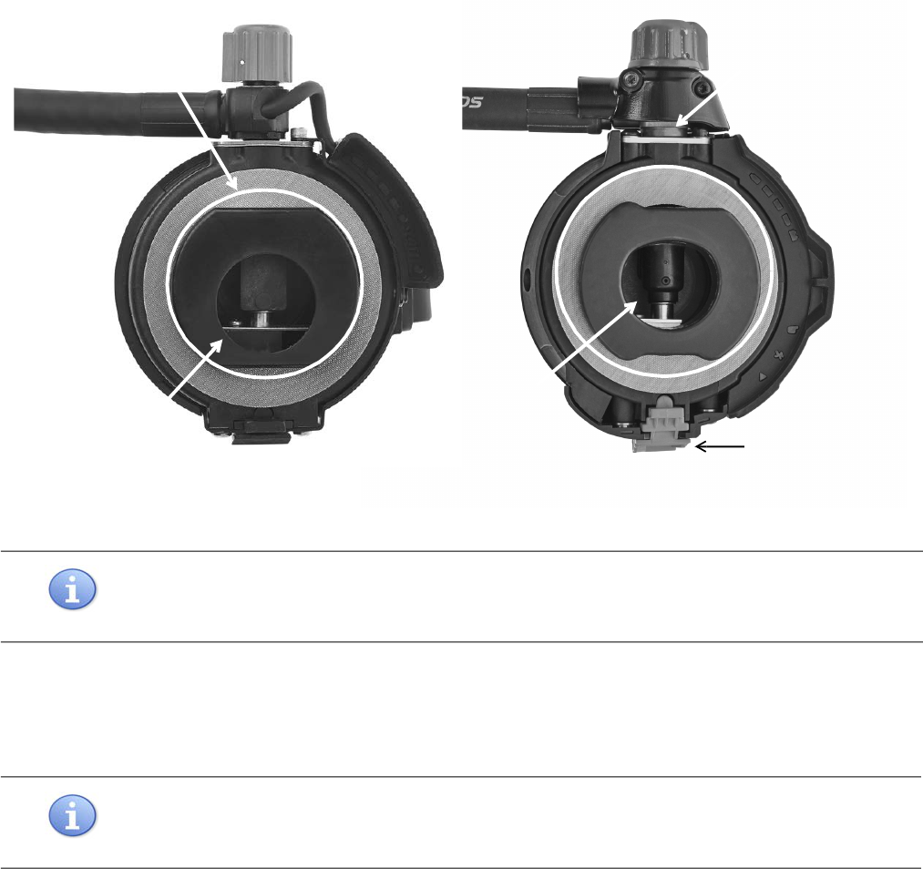
3 Inspect the inside of the regulator assembly through the regulator opening (see Figure 3-1). If excessive dirt or soil
is present, forward the regulator assembly to 3M-trained authorized personnel for thorough cleaning.
4 Engage the lock tab or latch. Close the purge knob by turning it fully clockwise.
5 Using a spray bottle, apply the sanitizing or disinfecting cleaner to the surfaces of the regulator opening and the
immediate area around the opening (see Figure 3-1). Be sure to cover the internal components completely with
the cleaning solution.
CAUTION
When using cleaning products, follow all of the manufacturer’s instructions. Improper use or handling of
these products may result in damage to the regulator.
CAUTION
When cleaning the regulator, do not use the following cleaning products:
• Bleach stronger than a 3% solution in water
• Solvents such as acetone, paint and lacquer thinner, benzene, or dry-cleaning fluid.
In addition, do not do the following:
• “Dunk and slosh”
• Autoclave or wash in an unapproved automatic washer
• Use a vapor degreaser/polisher
CLEANING THE RESPIRATOR
P/N 595360-01 Rev G 202004 45
Figure 3-1 Cleaning the mask-mounted regulator
6 Set the regulator aside for the required contact time prior to rinsing. The hypochlorite solution and the aqueous
solution of iodine require a 2-minute contact time.
7 Using gently running tap water or a spray bottle with drinking water, rinse the regulator inside and out.
8 Shake excess water out of regulator. Completely air dry the regulator before use.
9 If the regulator was disconnected from the air supply for cleaning, reconnect and open the purge valve to remove
any moisture from regulator spray bar. Close the purge valve.
10 Perform a regulator check after each cleaning by following steps listed in “To perform a regulator check”.
NOTE
Follow the user instructions for the cleaner. A specific contact time may be required for sanitizing or
disinfecting before rinsing.
NOTE
To speed drying of the regulator, gently blow dry with clean, dry breathing air of 30 psig maximum. Do not
use shop air or any other air containing lubricants or moisture.
Regulator
opening
Wet all areas within the
circle
Regulator
opening
Wet all areas
within the circle
Auto air-saver
switch/Regulator latch
E-Z FLO+
E-Z FLO C5

CLEANING & STORING THE RESPIRATOR
46 P/N 595360-01 Rev G 202004
To perform a regulator check
1 Make sure the respirator cylinder is at least 1/2 full to prevent the Vibralert from initiating and obscuring the
sound of air flowing from the regulator.
2 Verify that the air saver/donning switch is depressed on the E-Z Flo+ regulator or the auto air-saver switch is
engaged on the E-Z Flo C5 regulator latch.
3 Close the purge knob.
4 Reattach the regulator to the respirator (if removed for cleaning).
5 Slowly open the cylinder valve at least 1 full turn.
6 If you hear air flowing from the regulator, close the cylinder valve and repeat steps 2 through 5. If you still hear air
flow, close the cylinder valve fully, tag the unit for repair, and remove it from service.
7 Open the purge valve and observe the air flow from the regulator spray bar. Droplets of water indicate the
regulator is not dry. Dry the regulator according to step 8 of “To clean the mask-mounted regulator” on page 44
and repeat the regulator check.
NOTE
The regulator check is not intended to be a complete functional check of the respirator. Before your next
use of the respirator, perform a regular operational inspection as described in “
Chapter 1: Inspecting the
Respirator
” on page 11.
NOTE
If the cylinder is 1/3 full or less, the Vibralert will initiate. If the Vibralert does not initiate, tag the unit for
repair and remove it from service.

CLEANING THE RESPIRATOR
P/N 595360-01 Rev G 202004 47
Cleaning the Shoulder Harness and Waist Pad
You may clean the 3M Scott Air-Pak X3 Pro soft goods — shoulder harness, waist pad, UEBSS or dual EBSS pouch
(if installed), and straps — using a sponge and/or scrub brush (for spot cleaning) or in an extractor or commercial
washing machine (for machine washing).
In accordance with NFPA 1851 (Standard on Selection, Care, and Maintenance of Protective Ensembles for Structural
Fire Fighting and Proximity Fire Fighting), 3M recommends the following for cleaning the shoulder harness and waist
pad:
• Use a mild, liquid laundry detergent with a pH ranging from 6.0 to 10.5 for spot treating or machine washing.
Consult the detergent’s Material Safety Data Sheet (MSDS) for pH information. You may also use 3M™ 504
Respirator Cleaning Wipes or commercially available baby wipes to remove debris prior to cleaning.
• Use warm water with a temperature of 40 degrees C (105 degrees F) or less for rinsing or washing.
Spot Cleaning the Shoulder Harness and Waist Pad
Spot clean light spots or stains on the shoulder harness, waist pad, or straps. If you need to remove the soft goods
from the backframe before spot cleaning, see “Chapter 2: Soft Goods Assembly & Disassembly” on page 25.
To spot clean the shoulder harness and waist pad
1 Brush and/or rinse off any debris.
2 Apply the cleaning solution to the soiled areas according to the manufacturer’s instructions. Scrub the soiled
areas using a sponge or a soft-bristled brush such as a toothbrush or nail brush.
3 Rinse the area thoroughly with water.
4 Repeat steps 3 and 4 as needed for heavily soiled areas.
5 Set the soft goods aside to air dry. See “Drying the Shoulder Harness and Waist Pad” on page 49.
CAUTION
NFPA 1851, Standard on Selection, Care, and Maintenance of Protective Ensembles for Structural Fire
Fighting and Proximity Fire Fighting, recommends that you evaluate any equipment known or suspected to
be contaminated with hazardous materials or body fluids on the scene to assess the extent of contamination
and determine whether the equipment is to be isolated, tagged, or immediately retired from use. If the
equipment is suitable for reuse, flush it with water at the scene to remove contaminants and prevent their
spread beyond the scene. Wash the equipment separately from other equipment in a dedicated commercial
washing machine; avoid using home or public machines to prevent spread of the contaminants.
WARNING
Do not use chlorine bleach, chlorinated solvents, high-pressure water jets, or power washers to clean the
shoulder harness and waist pad. Do not dry clean. Any of these practices may damage the material, putting
you at risk for serious injury or death.
CAUTION
Use only the recommended cleaning wipes (3M™ 504 Respirator Cleaning Wipes) or commercially available
baby wipes to clean the shoulder harness and waist pad. Other cleaning wipes may contain solvents, which
may distort the colors of the soft goods.

CLEANING & STORING THE RESPIRATOR
48 P/N 595360-01 Rev G 202004
Machine Washing the Shoulder Harness and Waist Pad
Machine wash the shoulder harness, waist pad, and straps to remove dirt and stains.
• Clean your 3M Scott Air-Pak X3 Pro soft goods at least once every year.
• Place all soft goods in a mesh bag (P/N 31004024) before machine washing.
• Use a front-loading extractor or commercial washing machine with tumbling action to reduce potential
mechanical damage to the soft goods. If the machine has an adjustable drum RPM, set it so the g-force does not
exceed 100g. Refer to the manufacturer’s instructions for details.
To machine wash the shoulder harness and waist pad
1 Detach the shoulder harness, waist pad, straps, and UEBSS or dual EBSS pouch (if installed) from the backframe
as outlined in “Chapter 2: Soft Goods Assembly & Disassembly” on page 25.
2 Perform a visual inspection for soiling, contamination, physical damage, or thermal damage. See “Performing a
General Inspection” on page 12 in Chapter 1: Inspecting the Respirator.
3 If necessary, spot treat any heavily soiled areas. See “Spot Cleaning the Shoulder Harness and Waist Pad” on
page 47.
4 Close all fasteners (snaps and buckles) on the shoulder harness and waist pad assemblies, paying special
attention the following:
• Remove the regulator holder from the waist belt.
– Carefully pull the waist belt (on the side with the female buckle component) through the openings of the
regulator holder.
– Set the regulator holder aside.
• Buckle the male and female ends of the waist belt.
• Attach the waist pad retaining strap to the waist pad. Be sure to thread both ends through the sewn loops on
the waist pad and snap them in place on the waist pad.
• If you have a UEBSS or dual EBSS pouch, be sure to remove the UEBSS or dual EBSS hose and close all
fasteners on the pouch.
5 Place the soft goods in the mesh bag. Tighten the bag’s drawstrings and load the bag into the washing machine.
Do not overload the machine.
6 Follow the washing machine manufacturer’s instructions for adding laundry detergent, setting the water level and
temperature, adjusting the drum RPM, and starting a normal wash cycle.
CAUTION
If your equipment was exposed to contaminants but is suitable for reuse according to your organization’s
assessment procedure:
• Wash the equipment separately from other equipment in a dedicated commercial washing machine.
• Avoid using home or public machines to prevent spread of the contaminants.
CAUTION
Avoid using a top-loading washing machine as the agitators in such machines can damage the material and
seams of soft goods.

CLEANING THE RESPIRATOR
P/N 595360-01 Rev G 202004 49
7 Inspect the soft goods and rewash them if necessary.
Drying the Shoulder Harness and Waist Pad
3M recommends air-drying the shoulder harness, waist pad, and straps. Machine drying — even using the dryer’s “air
dry” or “no heat” setting — is not recommended.
To dry the shoulder harness and waist pad
1 Air dry the shoulder harness and waist pad by hanging them in a well ventilated area out of direct sunlight.
2 Be sure to dry the soft goods thoroughly before storing.
CAUTION
In accordance with NFPA 1851, if the washing machine is also used to clean items other than protective
garments or fire-fighting equipment, rinse the machine before and after use by completing a full wash cycle
without laundry but with detergent and the maximum amount of water. Select a water temperature between
49 and 52 degrees C (120 to 125 degrees F).
CAUTION
Do not machine dry the shoulder harness, waist pad, and straps — even using the dryer’s “air dry” or “no
heat” setting. Excessive heat during drying can damage the material and cause shrinkage.
CAUTION
Prolonged exposure to direct sunlight can degrade the material of your shoulder harness and waist pad.
CAUTION
Storage of wet or moist soft goods promotes the growth of mildew and bacteria, which can degrade the
integrity of your equipment and also cause health issues.

CLEANING & STORING THE RESPIRATOR
50 P/N 595360-01 Rev G 202004
Storing the Respirator
Respirators intended for routine use and respirators not routinely used but kept for emergency use must be stored in
areas where the temperature is maintained above freezing (32° F / 0° C). If it is necessary to store the respirator at a
temperature at or below freezing before its next use, you must take special care to verify that all components of the
respirator are thoroughly dried.
To prepare the respirator for storage
1 If you notice any damage or deterioration, remove the respirator from service and tag it for repair.
2 Verify that the respirator is thoroughly dry before storing.
3 Attach the regulator to the regulator holder on the waist belt of the respirator.
To detach or reattach a mask-mounted regulator equipped with a quick-disconnect from the respirator, see “In-
specting the Regulator” on page 17.
4 Place the clean and dry facepiece in a breathable storage bag to protect it until its next use. Store it in a manner
that will not distort the face seals.
5 Place the respirator in the carrying case, protective container, or in a suitable storage location.
To store the respirator on a wall
If a wall storage bracket is used to store the SCBA, follow the instructions of the bracket manufacturer for mounting
as well as for placing arms through the shoulder straps and freeing the respirator from the bracket.
To store the respirator in a vehicle
The method of storage of a respirator in a vehicle must minimize the possibility of injury to persons in or near the
vehicle while it is in motion, especially during rapid deceleration or acceleration, sharp turns, or a collision.
When storing or transporting an SCBA, its spare components, or related equipment within a vehicle, use one of the
following methods to secure the items:
• a positive mechanical means designed to hold the item in its stowed position
• in a compartment with a positive latching door, or
• in a closed container suitable to transport and contain the SCBA and/or its spare components and associated
equipment
If a vehicle mounting bracket is used to store the SCBA in a vehicle, follow the instructions of the bracket
manufacturer for mounting as well as for placing arms through the shoulder straps and freeing the respirator from the
bracket.
WARNING
Respirators must be thoroughly dry before storing. Residual moisture may freeze in cold temperatures or
may cause corrosion or other damage, which could cause a malfunction of the respirator. Such a malfunction
may result in serious injury or death.
CAUTION
Do not store the respirator with the regulator attached to the facepiece. Storing the respirator in this way
may damage the facepiece, which could lead to serious injury or death. Attach the regulator to the
facepiece only when you are ready to begin using the respirator.

P/N 595360-01 Rev G 202004 51
CHAPTER 4
REPLACING BATTERIES
This chapter provides instructions for changing the batteries in an 3M Scott Air-Pak X3 Pro SCBA with a Personal
Alert Safety System (PASS) device, also known as a distress alarm.
Before You Begin
Because certain accessories and features require batteries for operation, always verify that this equipment and its
accessories have fresh batteries before use.
Replacing Batteries in Respirators with PASS
3M Scott Air-Pak SCBAs equipped with a PASS device require 6 AA batteries for operation. The 6 batteries power
both the Heads-Up Display (HUD) and the PASS device; separate batteries in the gauge console are not required. Only
a trained operator should replace batteries in a clean, nonflammable area.
To replace the batteries
1 Close the respirator cylinder valve and open the regulator purge valve to let out all the trapped air.
2 Close the regulator purge valve.
3 Press the manual reset (yellow) button on the remote pressure gauge console twice.
A 15-second beep sequence may occur as the residual air bleeds off. The unit will sound a 2-tone chirp as the elec-
tronics are deactivated, and the green light will go out.
WARNING
Batteries are required for proper operation of this equipment. Failure to install batteries and to perform a
regular operational inspection may cause malfunction of the equipment, which could result in serious injury
or death.
WARNING
Change batteries only in areas known to be non-flammable and non-explosive. Changing batteries in a
flammable or explosive atmosphere may cause an ignition, which could result in serious injury or death.
CAUTION
Do not use tools to close the cylinder valve. Over-tightening the cylinder valve may cause damage that
could result in air leaking from the cylinder.
P/N 595360-01
202004
Rev G
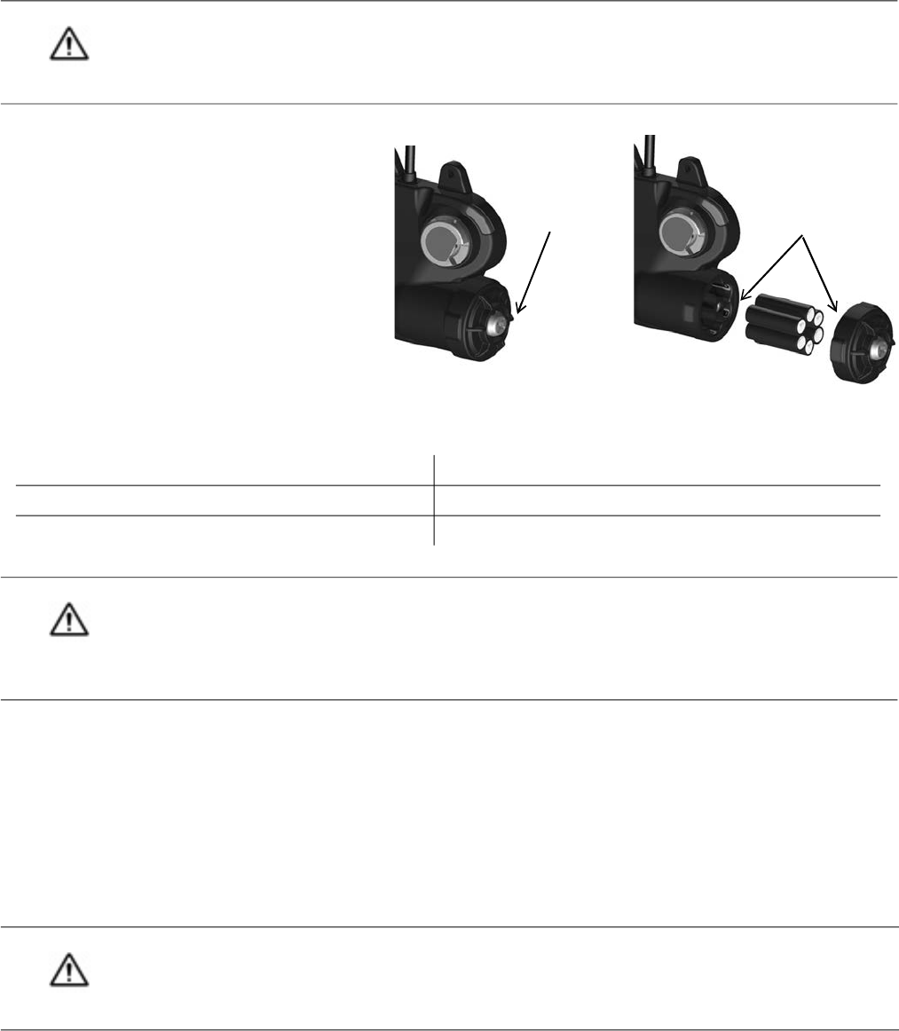
REPLACING BATTERIES
52 P/N 595360-01 Rev G 202004
4 Remove the cylinder.
5 Using a Phillips screwdriver, remove the
screws of the battery housing cover as shown
in Figure 4-1. Carefully remove the cover and
set it aside.
6 Remove the used batteries by sliding them out
of the battery compartment.
7 Install 6 new AA batteries of the same type.
The battery holder is marked with the required
style and orientation of the batteries.
Figure 4-1 Replacing batteries in a respirator with PASS
To maintain intrinsic safety, use 6 of one of the following types of 1.5 volt AA batteries:
8 Verify the correct orientation of batteries as shown on label inside the battery holder.
9 To ensure that the battery cover is water-tight after replacement, clean the sealing rib around the battery
compartment and sealing face of the cover by wiping with a clean damp to remove any dirt or foreign matter that
might prevent a proper seal.
10 Check the cover gasket for tears or cuts. If you find damage, remove the respirator from service and tag it for
repair by authorized personnel.
11 To install the battery cover, align the three grooves on the cover with the three tabs on the battery compartment.
Using a Phillips screwdriver, tighten the cover screw to 13-15 in-lbs torque.
When the batteries are properly installed and the battery covers are placed in position, all lights in the HUD will light
for approximately 20 seconds to verify operation.
12 Before returning the respirator to service, perform a regular operational check. See “Chapter 1: Inspecting the
Respirator” on page 11.
CAUTION
Always ensure that the cylinder value is off and the PASS device is completely inactive before changing
batteries. Never remove or replace batteries within a pressurized system, as damage to the electronic
components may occur.
Duracell Alkaline MN1500 Duracell Quantum QU1500
Duracell Alkaline MX1500 Energizer Alkaline EN91
Duracell Alkaline PC1500 Energizer Alkaline E91
WARNING
To reduce the risk of explosion, use batteries only from the list provided. Do not mix old batteries with
unused batteries. Always replace all batteries at the same time. Do not mix batteries from different
manufacturers. Unauthorized substitution of components may impair intrinsic safety and cause an explosion,
which could lead to serious injury or death.
CAUTION
Improper installation of the battery cover can cause overheating of batteries and damage to the product.
Always ensure that the alignment grooves on the battery cover are aligned with the tabs on the battery
compartment when installing the cover.
Use a
screwdriver to
loosen the
screw on the
battery cover
Replace the batteries.
Ensure that sealing
surfaces are clean
before replacing the
cap.
53
NOTES
54
NOTES
55

4320 Goldmine Road
Monroe, NC 28110
Telephone: (704) 291-8300
Technical Support: (800) 247-7257
Web: www.3MScott.com
©3M 2020. All rights reserved. 3M and Scott are trademarks of 3M.
