
Method 1669
Sampling Ambient Water for Trace Metals at EPA Water Quality
Criteria Levels
July 1996
U.S. Environmental Protection Agency
Office of Water
Engineering and Analysis Division (4303)
401 M Street S.W.
Washington, D.C. 20460

Method 1669
Acknowledgements
This sampling method was prepared under the direction of William A. Telliard of the
Engineering and Analysis Division (EAD) within the U.S. Environmental Agency's (EPA's) Office
of Science and Technology (OST). This sampling method was prepared under EPA Contract 68-
C3-0337 by the DynCorp Environmental Programs Division, with assistance from Interface, Inc.
The following researchers contributed to the philosophy behind this sampling method. Their
contribution is gratefully acknowledged:
Shier Berman, National Research Council, Ottawa, Ontario, Canada;
Nicholas Bloom, Frontier Geosciences Inc, Seattle, Washington;
Eric Crecelius, Battelle Marine Sciences Laboratory, Sequim, Washington;
Russell Flegal, University of California/Santa Cruz, California;
Gary Gill, Texas A&M University at Galveston, Texas;
Carlton Hunt and Dion Lewis, Battelle Ocean Sciences, Duxbury, Massachusetts;
Carl Watras, Wisconsin Department of Natural Resources, Boulder Junction, Wisconsin
Additional support was provided by Ted Martin of the EPA Office of Research and
Development's Environmental Monitoring Systems Laboratory in Cincinnati, Ohio and by Arthur
Horowitz of the U.S. Geological Survey.
This version of the method was prepared after observations of sampling teams from the
University of California at Santa Cruz, the Wisconsin Department of Natural Resources, the U.S.
Geological Survey, and Battelle Ocean Sciences. The assistance of personnel demonstrating the
sampling techniques used by these institutions is gratefully acknowledged.
Disclaimer
This sampling method has been reviewed and approved for publication by the Analytical
Methods Staff within the Engineering and Analysis Division of the U.S. Environmental Protection
Agency. Mention of trade names or commercial products does not constitute endorsement or
recommendation for use.
Further Information
For further information, contact:
W.A. Telliard
Engineering and Analysis Division (4303)
U.S. Environmental Protection Agency
401 M Street, SW
Washington, DC 20460
Phone: 202/260–7134
Fax: 202/260–7185
July 1996 ii

Method 1669
Introduction
This sampling method was designed to support water quality monitoring programs authorized
under the Clean Water Act. Section 304(a) of the Clean Water Act requires EPA to publish water
quality criteria that reflect the latest scientific knowledge concerning the physical fate (e.g.,
concentration and dispersal) of pollutants, the effects of pollutants on ecological and human
health, and the effect of pollutants on biological community diversity, productivity, and stability.
Section 303 of the Clean Water Act requires states to set a water quality standard for each body
of water within its boundaries. A state water quality standard consists of a designated use or
uses of a waterbody or a segment of a waterbody, the water quality criteria that are necessary
to protect the designated use or uses, and an antidegradation policy. These water quality
standards serve two purposes: (1) they establish the water quality goals for a specific
waterbody, and (2) they are the basis for establishing water quality-based treatment controls and
strategies beyond the technology-based controls required by Sections 301(b) and 306 of the Clean
Water Act.
In defining water quality standards, the state may use narrative criteria, numeric criteria, or both.
However, the 1987 amendments to the Clean Water Act required states to adopt numeric criteria
for toxic pollutants (designated in Section 307(a) of the Act) based on EPA Section 304(a) criteria
or other scientific data, when the discharge or presence of those toxic pollutants could reasonably
be expected to interfere with designated uses.
In some cases, these water quality criteria are as much as 280 times lower than those achievable
using existing EPA methods and required to support technology-based permits. Therefore, this
sampling method, and the analytical methods referenced in Table 1 of this document, were
developed by EPA to specifically address state needs for measuring toxic metals at water quality
criteria levels, when such measurements are necessary to protect designated uses in state water
quality standards. The latest criteria published by EPA are those listed in the National Toxics
Rule (57 FR 60848) and the Stay of Federal Water Quality Criteria for Metals (60 FR 22228).
These rules include water quality criteria for 13 metals, and it is these criteria on which this
sampling method and the referenced analytical methods are based.
In developing these methods, EPA found that one of the greatest difficulties in measuring
pollutants at these levels was precluding sample contamination during collection, transport, and
analysis. The degree of difficulty, however, is highly dependent on the metal and site-specific
conditions. This method, therefore, is designed to provide the level of protection necessary to
preclude contamination in nearly all situations. It is also designed to provide the procedures
necessary to produce reliable results at the lowest possible water quality criteria published by
EPA. In recognition of the variety of situations to which this method may be applied, and in
recognition of continuing technological advances, the method is performance-based. Alternative
procedures may be used, so long as those procedures are demonstrated to yield reliable results.
Requests for additional copies of this method should be directed to:
U.S. EPA NCEPI
11029 Kenwood Road
Cincinnati, OH 45242
513/489–8190
July 1996 iii

Method 1669
Note: This document is intended as guidance only. Use of the terms "must," "may,"
and "should" are included to mean that EPA believes that these procedures must, may,
or should be followed in order to produce the desired results when using this
guidance. In addition, the guidance is intended to be performance-based, in that the
use of less stringent procedures may be used so long as neither samples nor blanks are
contaminated when following those modified procedures. Because the only way to
measure the performance of the modified procedures is through the collection and
analysis of uncontaminated blank samples in accordance with this guidance and the
referenced methods, it is highly recommended that any modifications be thoroughly
evaluated and demonstrated to be effective before field samples are collected.
July 1996 iv

Method 1669
Sampling Ambient Water for Determination of Metals at EPA Water Quality
Criteria Levels
1.0 Scope and Application
1.1 This method is for the collection and filtration of ambient water samples for subsequent
determination of total and dissolved metals at the levels listed in Table 1. It is designed
to support the implementation of water quality monitoring and permitting programs
administered under the Clean Water Act.
1.2 This method is applicable to the metals listed below and other metals, metals species, and
elements amenable to determination at trace levels.
Chemical Abstract Services
Analyte Symbol Registry Number (CASRN)
Antimony (Sb) 7440-36-0
Arsenic (As) 7440-38-2
Cadmium (Cd) 7440-43-9
Chromium (III) Cr
+3
16065-83-1
Chromium (VI) Cr
+6
18540-29-9
Copper (Cu) 7440-50-8
Lead (Pb) 7439-92-1
Mercury (Hg) 7439-97-6
Nickel (Ni) 7440-02-0
Selenium (Se) 7782-49-2
Silver (Ag) 7440-22-4
Thallium (Tl) 7440-28-0
Zinc (Zn) 7440-66-6
1.3 This method is accompanied by the 1600 series methods listed in Table 1. These methods
include the sample handling, analysis, and quality control procedures necessary for
reliable determination of trace metals in aqueous samples.
1.4 This method is not intended for determination of metals at concentrations normally
found in treated and untreated discharges from industrial facilities. Existing regulations
(40 CFR Parts 400-500) typically limit concentrations in industrial discharges to the mid
to high part-per-billion (ppb) range, whereas ambient metals concentrations are normally
in the low part-per-trillion (ppt) to low ppb range. This guidance is therefore directed
at the collection of samples to be measured at or near the levels listed in Table 1. Actual
concentration ranges to which this guidance is applicable will be dependent on the
sample matrix, dilution levels, and other laboratory operating conditions.
1.5 The ease of contaminating ambient water samples with the metal(s) of interest and
interfering substances cannot be overemphasized. This method includes sampling
techniques that should maximize the ability of the sampling team to collect samples
reliably and eliminate sample contamination. These techniques are given in Section 8.0
and are based on findings of researchers performing trace metals analyses (References 1-
9).
July 1996 1

Method 1669
1.6 Clean and Ultraclean—The terms "clean" and "ultraclean" have been used in other
Agency guidance to describe the techniques needed to reduce or eliminate contamination
in trace metals determinations. These terms are not used in this sampling method due
to a lack of exact definitions. However, the information provided in this method is
consistent with summary guidance on clean and ultraclean techniques (Reference 10).
1.7 This sampling method follows the EPA Environmental Methods Management Council's
"Format for Method Documentation" (Reference 11).
1.8 Method 1669 is "performance-based"; i.e., an alternate sampling procedure or technique
may be used, so long as neither samples nor blanks are contaminated when following the
alternate procedures. Because the only way to measure the performance of the alternate
procedures is through the collection and analysis of uncontaminated blank samples in
accordance with this guidance and the methods referenced in Table 1, it is highly
recommended that any modifications be thoroughly evaluated and demonstrated to be
effective before field samples are collected. Section 9.2 provides additional details on the
tests and documentation required to support equivalent performance.
1.9 For dissolved metal determinations, samples must be filtered through a 0.45 µm capsule
filter at the field site. The filtering procedures are described in this method. The filtered
samples may be preserved in the field or transported to the laboratory for preservation.
Procedures for field preservation are detailed in this sampling method; procedures for
laboratory preservation are provided in the methods referenced in Table 1. Preservation
requirements are summarized in Table 2.
1.10 The procedures in this method are for use only by personnel thoroughly trained in the
collection of samples for determination of metals at ambient water quality control levels.
2.0 Summary of Method
2.1 Before samples are collected, all sampling equipment and sample containers are cleaned
in a laboratory or cleaning facility using detergent, mineral acids, and reagent water as
described in the methods referenced in Table 1. The laboratory or cleaning facility is
responsible for generating an acceptable equipment blank to demonstrate that the
sampling equipment and containers are free from trace metals contamination before they
are shipped to the field sampling team. An acceptable blank is one that is free from
contamination below the minimum level (ML) specified in the referenced analytical
method (Section 9.3).
2.2 After cleaning, sample containers are filled with weak acid solution, individually double-
bagged, and shipped to the sampling site. All sampling equipment is also bagged for
storage or shipment.
NOTE: EPA has found that, in some cases, it may be possible to empty the weak acid solution
from the bottle immediately prior to transport to the field site. In this case, the bottle should be
refilled with reagent water (Section 7.1).
2.3 The laboratory or cleaning facility must prepare a large carboy or other appropriate clean
container filled with reagent water (Section 7.1) for use with collection of field blanks
during sampling activities. The reagent-water-filled container should be shipped to the
field site and handled as all other sample containers and sampling equipment. At least
July 1996 2

Method 1669
one field blank should be processed per site, or one per every ten samples, whichever is
more frequent (Section 9.4). If samples are to be collected for determination of trivalent
chromium, the sampling team processes additional QC aliquots are processed as
described in Section 9.6.
2.4 Upon arrival at the sampling site, one member of the two-person sampling team is
designated as "dirty hands"; the second member is designated as "clean hands." All
operations involving contact with the sample bottle and transfer of the sample from the
sample collection device to the sample bottle are handled by the individual designated
as "clean hands." "Dirty hands" is responsible for preparation of the sampler (except the
sample container itself), operation of any machinery, and for all other activities that do
not involve direct contact with the sample.
2.5 All sampling equipment and sample containers used for metals determinations at or near
the levels listed in Table 1 must be nonmetallic and free from any material that may
contain metals.
2.6 Sampling personnel are required to wear clean, nontalc gloves at all times when handling
sampling equipment and sample containers.
2.7 In addition to processing field blanks at each site, a field duplicate must be collected at
each sampling site, or one field duplicate per every 10 samples, whichever is more
frequent (Section 9.5). Section 9.0 gives a complete description of quality control
requirements.
2.8 Sampling
2.8.1 Whenever possible, samples are collected facing upstream and upwind to
minimize introduction of contamination.
2.8.2 Samples may be collected while working from a boat or while on land.
2.8.3 Surface samples are collected using a grab sampling technique. The principle of
the grab technique is to fill a sample bottle by rapid immersion in water and
capping to minimize exposure to airborne particulate matter.
2.8.4 Subsurface samples are collected by suction of the sample into an immersed
sample bottle or by pumping the sample to the surface.
2.9 Samples for dissolved metals are filtered through a 0.45 µm capsule filter at the field site.
After filtering, the samples are double-bagged and iced immediately. Sample containers
are shipped to the analytical laboratory. The sampling equipment is shipped to the
laboratory or cleaning facility for recleaning.
2.10 Acid preservation of samples is performed in the field or in the laboratory. Field
preservation is necessary for determinations of trivalent chromium. It has also been
shown that field preservation can increase sample holding times for hexavalent
chromium to 30 days; therefore it is recommended that preservation of samples for
hexavalent chromium be performed in the field. For other metals, however, the sampling
team may prefer to utilize laboratory preservation of samples to expedite field operations
and to minimize the potential for sample contamination.
July 1996 3

Method 1669
2.11 Sampling activities must be documented through paper or computerized sample tracking
systems.
3.0 Definitions
3.1 Apparatus—Throughout this method, the sample containers, sampling devices,
instrumentation, and all other materials and devices used in sample collection, sample
processing, and sample analysis activities will be referred to collectively as the
Apparatus.
3.2 Definitions of other terms are given in the Glossary (Section 15.0) at the end of this
method.
4.0 Contamination and Interferences
4.1 Contamination Problems in Trace Metals Analysis
4.1.1 Preventing ambient water samples from becoming contaminated during the
sampling and analytical process is the greatest challenge faced in trace metals
determinations. In recent years, it has been shown that much of the historical
trace metals data collected in ambient water are erroneously high because the
concentrations reflect contamination from sampling and analysis rather than
ambient levels (Reference 12). Therefore, it is imperative that extreme care be
taken to avoid contamination when collecting and analyzing ambient water
samples for trace metals.
4.1.2 There are numerous routes by which samples may become contaminated.
Potential sources of trace metals contamination during sampling include metallic
or metal-containing sampling equipment, containers, labware (e.g. talc gloves that
contain high levels of zinc), reagents, and deionized water; improperly cleaned
and stored equipment, labware, and reagents; and atmospheric inputs such as dirt
and dust from automobile exhaust, cigarette smoke, nearby roads, bridges, wires,
and poles. Even human contact can be a source of trace metals contamination.
For example, it has been demonstrated that dental work (e.g., mercury amalgam
fillings) in the mouths of laboratory personnel can contaminate samples that are
directly exposed to exhalation (Reference 3).
4.2 Contamination Control
4.2.1 Philosophy—The philosophy behind contamination control is to ensure that any
object or substance that contacts the sample is nonmetallic and free from any
material that may contain metals of concern.
4.2.1.1 The integrity of the results produced cannot be compromised by
contamination of samples. Requirements and suggestions for controlling
sample contamination are given in this sampling method and in the
analytical methods referenced in Table 1.
4.2.1.2 Substances in a sample or in the surrounding environment cannot be
allowed to contaminate the Apparatus used to collect samples for trace
metals measurements. Requirements and suggestions for protecting the
July 1996 4

Method 1669
Apparatus are given in this sampling method and in the methods
referenced in Table 1.
4.2.1.3 While contamination control is essential, personnel health and safety
remain the highest priority. Requirements and suggestions for personnel
safety are given in Section 5 of this sampling method and in the methods
referenced in Table 1.
4.2.2 Avoiding contamination—The best way to control contamination is to completely
avoid exposure of the sample and Apparatus to contamination in the first place.
Avoiding exposure means performing operations in an area known to be free
from contamination. Two of the most important factors in avoiding/reducing
sample contamination are (1) an awareness of potential sources of contamination
and (2) strict attention to work being performed. Therefore, it is imperative that
the procedures described in this method be carried out by well trained,
experienced personnel. Documentation of training should be kept on file and
readily available for review.
4.2.2.1 Minimize exposure—The Apparatus that will contact samples or blanks
should only be opened or exposed in a clean room, clean bench, glove
box, or clean plastic bag, so that exposure to atmospheric inputs is
minimized. When not being used, the Apparatus should be covered with
clean plastic wrap, stored in the clean bench or in a plastic box or glove
box, or bagged in clean, colorless zip-type bags. Minimizing the time
between cleaning and use will also reduce contamination.
4.2.2.2 Wear gloves—Sampling personnel must wear clean, nontalc gloves
(Section 6.7) during all operations involving handling of the Apparatus,
samples, and blanks. Only clean gloves may touch the Apparatus. If
another object or substance is touched, the glove(s) must be changed
before again handling the Apparatus. If it is even suspected that gloves
have become contaminated, work must be halted, the contaminated gloves
removed, and a new pair of clean gloves put on. Wearing multiple layers
of clean gloves will allow the old pair to be quickly stripped with minimal
disruption to the work activity.
4.2.2.3 Use metal-free Apparatus—All Apparatus used for metals determinations
at the levels listed in Table 1 must be nonmetallic and free of material that
may contain metals. When it is not possible to obtain equipment that is
completely free of the metal(s) of interest, the sample should not come
into direct contact with the equipment.
4.2.2.3.1 Construction materials—Only the following materials
should come in contact with samples: fluoropolymer (FEP,
PTFE), conventional or linear polyethylene, polycarbonate,
polysulfone, polypropylene, or ultrapure quartz. PTFE is
less desirable than FEP because the sintered material in
PTFE may contain contaminants and is susceptible to
serious memory effects (Reference 6). Fluoropolymer or
glass containers should be used for samples that will be
analyzed for mercury because mercury vapors can diffuse
July 1996 5

Method 1669
in or out of other materials, resulting either in
contamination or low-biased results (Reference 3). Metal
must not be used under any circumstance. Regardless of
construction, all materials that will directly or indirectly
contact the sample must be cleaned using the procedures
described in the referenced analytical methods (see Table 1)
and must be known to be clean and metal-free before
proceeding.
4.2.2.3.2 The following materials have been found to contain trace
metals and must not be used to hold liquids that come in
contact with the sample or must not contact the sample,
unless these materials have been shown to be free of the
metals of interest at the desired level: Pyrex, Kimax,
methacrylate, polyvinylchloride, nylon, and Vycor
(Reference 6). In addition, highly colored plastics, paper
cap liners, pigments used to mark increments on plastics,
and rubber all contain trace levels of metals and must be
avoided (Reference 13).
4.2.2.3.3 Serialization—Serial numbers should be indelibly marked
or etched on each piece of Apparatus so that contamination
can be traced, and logbooks should be maintained to track
the sample from the container through the sampling
process to shipment to the laboratory. Chain-of-custody
procedures may also be used if warranted so that
contamination can be traced to particular handling
procedures or lab personnel.
4.2.2.3.4 The Apparatus should be clean when the sampling team
receives it. If there are any indications that the Apparatus
is not clean (e.g., a ripped storage bag), an assessment of
the likelihood of contamination must be made. Sampling
must not proceed if it is possible that the Apparatus is
contaminated. If the Apparatus is contaminated, it must be
returned to the laboratory or cleaning facility for proper
cleaning before any sampling activity resumes.
4.2.2.3.5 Details for recleaning the Apparatus between collection of
individual samples are provided in Section 10.0.
4.2.2.4 Avoid sources of contamination—Avoid contamination by being aware of
potential sources and routes of contamination.
4.2.2.4.1 Contamination by carryover—Contamination may occur
when a sample containing low concentrations of metals is
processed immediately after a sample containing relatively
high concentrations of these metals. At sites where more
than one sample will be collected, the sample known or
expected to contain the lowest concentration of metals
should be collected first with the sample containing the
July 1996 6

Method 1669
highest levels collected last (Section 8.1.4). This will help
minimize carryover of metals from high- concentration
samples to low- concentration samples. If the sampling
team does not have prior knowledge of the waterbody, or
when necessary, the sample collection system should be
rinsed with dilute acid and reagent water between samples
and followed by collection of a field blank (Section 10.3).
4.2.2.4.2 Contamination by samples—Significant contamination of
the Apparatus may result when untreated effluents, in-
process waters, landfill leachates, and other samples
containing mid- to high-level concentrations of inorganic
substances are processed. As stated in Section 1.0, this
sampling method is not intended for application to these
samples, and samples containing high concentrations of
metals must not be collected, processed, or shipped at the
same time as samples being collected for trace metals
determinations.
4.2.2.4.3 Contamination by indirect contact—Apparatus that may
not directly contact samples may still be a source of
contamination. For example, clean tubing placed in a dirty
plastic bag may pick up contamination from the bag and
subsequently transfer the contamination to the sample.
Therefore, it is imperative that every piece of the Apparatus
that is directly or indirectly used in the collection of
ambient water samples be cleaned as specified in the
analytical method(s) referenced in Table 1.
4.2.2.4.4 Contamination by airborne particulate matter—Less
obvious substances capable of contaminating samples
include airborne particles. Samples may be contaminated
by airborne dust, dirt, particulate matter, or vapors from
automobile exhaust; cigarette smoke; nearby corroded or
rusted bridges, pipes, poles, or wires; nearby roads; and
even human breath (Section 4.1.2). Whenever possible, the
sampling activity should occur as far as possible from
sources of airborne contamination (Section 8.1.3). Areas
where nearby soil is bare and subject to wind erosion
should be avoided.
4.3 Interferences—Interferences resulting from samples will vary considerably from source
to source, depending on the diversity of the site being sampled. If a sample is suspected
of containing substances that may interfere in the determination of trace metals, sufficient
sample should be collected to allow the laboratory to identify and overcome interference
problems.
5.0 Safety
5.1 The toxicity or carcinogenicity of the chemicals used in this method has not been
precisely determined; however, these chemicals should be treated as a potential health
July 1996 7

Method 1669
hazard. Exposure should be reduced to the lowest possible level. Sampling teams are
responsible for maintaining a current awareness file of OSHA regulations for the safe
handling of the chemicals specified in this method. A reference file of Material Safety
Data Sheets should also be made available to all personnel involved in sampling. It is
also suggested that the organization responsible perform personal hygiene monitoring
of each sampling team member who uses this method and that the results of this
monitoring be made available to the member.
5.2 Operating in and around waterbodies carries the inherent risk of drowning. Life jackets
must be worn when operating from a boat, when sampling in more than a few feet of
water, or when sampling in swift currents.
5.3 Collecting samples in cold weather, especially around cold water bodies, carries the risk
of hypothermia, and collecting samples in extremely hot and humid weather carries the
risk of dehydration and heat stroke. Sampling team members should wear adequate
clothing for protection in cold weather and should carry an adequate supply of water or
other liquids for protection against dehydration in hot weather.
6.0 Apparatus and Materials
NOTE: Brand names, suppliers, and part numbers are for illustration only and no endorsement is
implied. Equivalent performance may be achieved using apparatus and materials other than those specified
here. Meeting the performance requirements of this method is the responsibility of the sampling team and
laboratory.
6.1 All sampling equipment and sample containers must be precleaned in a laboratory or
cleaning facility, as described in the methods referenced in Table 1, before they are
shipped to the field site. Performance criteria for equipment cleaning is described in the
referenced methods. To minimize difficulties in sampling, the equipment should be
packaged and arranged to minimize field preparation.
6.2 Materials such as gloves (Section 6.7), storage bags (Section 6.8), and plastic wrap (Section
6.9), may be used new without additional cleaning unless the results of the equipment
blank pinpoint any of these materials as a source of contamination. In this case, either
a different supplier must be obtained or the materials must be cleaned.
6.3 Sample Bottles—Fluoropolymer (FEP, PTFE), conventional or linear polyethylene,
polycarbonate, or polypropylene; 500 mL or 1 L with lids. If mercury is a target analyte,
fluoropolymer or glass bottles should be used. Refer to the methods referenced in Table
1 for bottle cleaning procedures.
6.3.1 Cleaned sample bottles should be filled with 0.1% HCl (v/v). In some cases, it
may be possible to empty the weak acid solution from the sample bottle
immediately prior to transport to the field site. In this case, the bottle should be
refilled with reagent water (Section 7.1).
6.3.2 Whenever possible, sampling devices should be cleaned and prepared for field
use in a class 100 clean room. Preparation of the devices in the field should be
done within the glove bag (Section 6.6). Regardless of design, sampling devices
must be constructed of nonmetallic material (Section 4.2.2.3.1) and free from
material that contains metals. Fluoropolymer or other material shown not to
July 1996 8

Method 1669
adsorb or contribute mercury must be used if mercury is a target analyte;
otherwise, polyethylene, polycarbonate, or polypropylene are acceptable.
Commercially available sampling devices may be used provided that any metallic
or metal-containing parts are replaced with parts constructed of nonmetallic
material.
6.4 Surface Sampling Devices—Surface samples are collected using a grab sampling
technique. Samples may be collected manually by direct submersion of the bottle into
the water or by using a grab sampling device. Examples of grab samplers are shown in
Figures 1 and 2 and may be used at sites where depth profiling is neither practical nor
necessary.
6.4.1 The grab sampler in Figure 1 consists of a heavy fluoropolymer collar fastened
to the end of a 2-m-long polyethylene pole, which serves to remove the sampling
personnel from the immediate vicinity of the sampling point. The collar holds the
sample bottle. A fluoropolymer closing mechanism, threaded onto the bottle,
enables the sampler to open and close the bottle under water, thereby avoiding
surface microlayer contamination (Reference 14). Polyethylene, polycarbonate,
and polypropylene are also acceptable construction materials unless mercury is
a target analyte. Assembly of the cleaned sampling device is as follows (refer to
Figure 1):
6.4.1.1 Thread the pull cord (with the closing mechanism attached) through the
guides and secure the pull ring with a simple knot. Screw a sample bottle
onto the closing device and insert the bottle into the collar. Cock the
closing plate so that the plate is pushed away from the operator.
6.4.1.2 The cleaned and assembled sampling device should be stored in a double
layer of large, clean zip-type polyethylene bags or wrapped in two layers
of clean polyethylene wrap if it will not be used immediately.
6.4.2 An alternate grab sampler design is shown in Figure 2. This grab sampler is used
for discrete water samples and is constructed so that a capped clean bottle can be
submerged, the cap removed, sample collected, and bottle recapped at a selected
depth. This device eliminates sample contact with conventional samplers (e.g.,
Niskin bottles), thereby reducing the risk of extraneous contamination. Because
a fresh bottle is used for each sample, carryover from previous samples is
eliminated (Reference 15).
6.5 Subsurface Sampling Devices—Subsurface sample collection may be appropriate in lakes
and sluggish deep river environments or where depth profiling is determined to be
necessary. Subsurface samples are collected by pumping the sample into a sample bottle.
Examples of subsurface collection systems include the jar system device shown in Figure
3 and described in Section 6.5.1 or the continuous-flow apparatus shown in Figure 4 and
described in Section 6.5.2.
6.5.1 Jar sampler (Reference 14)—The jar sampler (Figure 3) is comprised of a heavy
fluoropolymer 1-L jar with a fluoropolymer lid equipped with two 1/4 in.
fluoropolymer fittings. Sample enters the jar through a short length of
fluoropolymer tubing inserted into one fitting. Sample is pulled into the jar by
pumping on fluoropolymer tubing attached to the other fitting. A thick
July 1996 9

Method 1669
fluoropolymer plate supports the jar and provides attachment points for a
fluoropolymer safety line and fluoropolymer torpedo counterweight.
6.5.1.1 Advantages of the jar sampler for depth sampling are (1) all wetted
surfaces are fluoropolymer and can be rigorously cleaned; (2) the sample
is collected into a sample jar from which the sample is readily recovered,
and the jar can be easily recleaned; (3) the suction device (a peristaltic or
rotary vacuum pump, Section 6.15) is located in the boat, isolated from the
sampling jar; (4) the sampling jar can be continuously flushed with
sample, at sampling depth, to equilibrate the system; and (5) the sample
does not travel through long lengths of tubing that are more difficult to
clean and keep clean (Reference 14). In addition, the device is designed
to eliminate atmospheric contact with the sample during collection.
6.5.1.2 To assemble the cleaned jar sampler, screw the torpedo weight onto the
machined bolt attached to the support plate of the jar sampler. Attach a
section of the 1/4 in. o.d. tubing to the jar by inserting the tubing into the
fitting on the lid and pushing down into the jar until approximately 8 cm
from the bottom. Tighten the fitting nut securely. Attach the solid safety
line to the jar sampler using a bowline knot to the loop affixed to the
support plate.
6.5.1.3 For the tubing connecting the pump to the sampler, tubing lengths of up
to 12 m have been used successfully (Reference 14).
6.5.2 Continuous-flow sampler (References 16-17)—This sampling system, shown in
Figure 4, consists of a peristaltic or submersible pump and one or more lengths
of precleaned fluoropolymer or styrene/ethylene/butylene/ silicone (SEBS)
tubing. A filter is added to the sampling train when sampling for dissolved
metals.
6.5.2.1 Advantages of this sampling system include (1) all wetted surfaces are
fluoropolymer or SEBS and can be readily cleaned; (2) the suction device
is located in the boat, isolated from the sample bottle; (3) the sample does
not travel through long lengths of tubing that are difficult to clean and
keep clean; and (4) in-line filtration is possible, minimizing field handling
requirements for dissolved metals samples.
6.5.2.2 The sampling team assembles the system in the field as described in
Section 8.2.8. System components include an optional polyethylene pole
to remove sampling personnel from the immediate vicinity of the
sampling point and the pump, tubing, filter, and filter holder listed in
Sections 6.14 and 6.15.
6.6 Field-Portable Glove Bag—I2R, Model R-37-37H (nontalc), or equivalent. Alternately, a
portable glove box may be constructed with a nonmetallic (PVC pipe or other suitable
material) frame and a frame cover made of an inexpensive, disposable, nonmetallic
material (e.g., a thin-walled polyethylene bag) (Reference 7).
10 July 1996

Method 1669
6.7 Gloves—Clean, nontalc polyethylene, latex, vinyl, or PVC; various lengths. Shoulder-
length gloves are needed if samples are to be collected by direct submersion of the
sample bottle into the water or when sampling for mercury.
6.7.1 Gloves, shoulder-length polyethylene—Associated Bag Co., Milwaukee, WI, 66-3-
301, or equivalent.
6.7.2 Gloves, PVC—Fisher Scientific Part No. 11-394-100B, or equivalent.
6.8 Storage Bags—Clean, zip-type, nonvented, colorless polyethylene (various sizes).
6.9 Plastic Wrap—Clean, colorless polyethylene.
6.10 Cooler—Clean, nonmetallic, with white interior for shipping samples.
6.11 Ice or Chemical Refrigerant Packs—To keep samples chilled in the cooler during
shipment.
6.12 Wind Suit—Pamida, or equivalent.
NOTE: This equipment is necessary only for collection of metals, such as mercury, that are known to
have elevated atmospheric concentrations.
6.12.1 An unlined, long-sleeved wind suit consisting of pants and jacket and constructed
of nylon or other synthetic fiber is worn when sampling for mercury to prevent
mercury adsorbed onto cotton or other clothing materials from contaminating
samples.
6.12.2 Washing and drying—The wind suit is washed by itself or with other wind suits
only in a home or commercial washing machine and dried in a clothes dryer. The
clothes dryer must be thoroughly vacuumed, including the lint filter, to remove
all traces of lint before drying. After drying, the wind suit is folded and stored
in a clean polyethylene bag for shipment to the sample site.
6.13 Boat
6.13.1 For most situations (e.g., most metals under most conditions), the use of an
existing, available boat is acceptable. A flat-bottom, Boston Whaler-type boat is
preferred because sampling materials can be stored with reduced chance of
tipping.
6.13.1.1 Immediately before use, the boat should be washed with water
from the sampling site away from any sampling points to remove
any dust or dirt accumulation.
6.13.1.2 Samples should be collected upstream of boat movement.
6.13.2 For mercury, and for situations in which the presence of contaminants cannot
otherwise be controlled below detectable levels, the following equipment and
precautions may be necessary:
July 1996 11

Method 1669
6.13.2.1 A metal-free (e.g., fiberglass) boat, along with wooden or fiberglass
oars. Gasoline- or diesel-fueled boat motors should be avoided
when possible because the exhaust can be a source of
contamination. If the body of water is large enough to require use
of a boat motor, the engine should be shut off at a distance far
enough from the sampling point to avoid contamination, and the
sampling team should manually propel the boat to the sampling
point. Samples should be collected upstream of boat movement.
6.13.2.2 Before first use, the boat should be cleaned and stored in an area
that minimizes exposure to dust and atmospheric particles. For
example, cleaned boats should not be stored in an area that would
allow exposure to automobile exhaust or industrial pollution.
6.13.2.3 The boat should be frequently visually inspected for possible
contamination.
6.13.2.4 After sampling, the boat should be returned to the laboratory or
cleaning facility, cleaned as necessary, and stored away from any
sources of contamination until next use.
6.14 Filtration Apparatus—Required when collecting samples for dissolved metals
determinations.
6.14.1 Filter—0.45 µm, 15 mm diameter or larger, tortuous-path capsule filters (Reference
18), Gelman Supor 12175, or equivalent.
6.14.2 Filter holder—For mounting filter to the gunwale of the boat. Rod or pipe made
from plastic material and mounted with plastic clamps.
NOTE: A filter holder may not be required if one or a few samples are to be collected. For these cases,
it may only be necessary to attach the filter to the outlet of the tubing connected to the pump.
6.15 Pump and Pump Apparatus—Required for use with the jar sampling system
(Section 6.5.1) or the continuous-flow system (Section 6.5.2). Peristaltic pump; 115 V a.c.,
12 V d.c., internal battery, variable-speed, single-head, Cole-Parmer, portable, "Masterflex
L/S," Catalog No. H-07570-10 drive with Quick Load pump head, Catalog No. H-07021-
24, or equivalent.
NOTE: Equivalent pumps may include rotary vacuum, submersible, or other pumps free from metals and
suitable to meet the site-specific depth sampling needs.
6.15.1 Cleaning—Peristaltic pump modules do not require cleaning. However, nearly
all peristaltic pumps contain a metal head and metal controls. Touching the head
or controls necessitates changing of gloves before touching the Apparatus. If a
submersible pump is used, a large volume of sample should be pumped to clean
the stainless steel shaft (hidden behind the impeller) that comes in contact with
the sample. Pumps with metal impellers should not be used.
12 July 1996

Method 1669
6.15.2 Tubing—For use with peristaltic pump. SEBS resin, approximately 3/8 in. i.d. by
approximately 3 ft, Cole-Parmer size 18, Cat. No. G-06464-18, or approximately
1/4 in. i.d., Cole-Parmer size 17, Catalog No. G-06464-17, or equivalent. Tubing
is cleaned by soaking in 5-10% HCl solution for 8-24 hours, rinsing with reagent
water in a clean bench in a clean room, and drying in the clean bench by purging
with mercury-free air or nitrogen. After drying, the tubing is double-bagged in
clear polyethylene bags, serialized with a unique number, and stored until use.
6.15.3 Tubing—For connection to peristaltic pump tubing. Fluoropolymer, 3/8 or
1/4 in. o.d., in lengths as required to reach the point of sampling. If sampling
will be at some depth from the end of a boom extended from a boat, sufficient
tubing to extend to the end of the boom and to the depth will be required.
Cleaning of the fluoropolymer can be the same as cleaning the tubing for the
rotary vacuum pump (Section 6.15.1.2). If necessary, more aggressive cleaning
(e.g., concentrated nitric acid) may be used.
6.15.4 Batteries to operate submersible pump—12 V, 2.6 amp, gel cell, YUASA NP2.6-12,
or equivalent. A 2 amp fuse connected at the positive battery terminal is strongly
recommended to prevent short circuits from overheating the battery. A 12 V,
lead-acid automobile or marine battery may be more suitable for extensive
pumping.
6.15.5 Tubing connectors—Appropriately sized PVC, clear polyethylene, or
fluoropolymer "barbed" straight connectors cleaned as the tubing above. Used to
connect multiple lengths of tubing.
6.16 Carboy—For collection and storage of dilute waste acids used to store bottles.
6.17 Apparatus—For field preservation of aliquots for trivalent chromium determinations.
6.17.1 Fluoropolymer forceps—1 L fluoropolymer jar, and 30 mL fluoropolymer vials
with screw-caps (one vial per sample and blank). It is recommended that 1 mL
of ultrapure nitric acid (Section 7.3) be added to each vial prior to transport to the
field to simplify field handling activities (See Section 8.4.4.6).
6.17.2 Filters—0.4 µm, 47 mm polycarbonate Nuclepore (or equivalent). Filters are
cleaned as follows. Fill a 1 L fluoropolymer jar approximately two-thirds full
with 1 N nitric acid. Using fluoropolymer forceps, place individual filters in the
fluoropolymer jar. Allow the filters to soak for 48 hours. Discard the acid, and
rinse five times with reagent water. Fill the jar with reagent water, and soak the
filters for 24 hours. Remove the filters when ready for use, and using
fluoropolymer forceps, place them on the filter apparatus (Section 6.17.3).
6.17.3 Vacuum filtration apparatus—Millipore 47 mm size, or equivalent, vacuum pump
and power source (and extension cords, if necessary) to operate the pump.
6.17.4 Eppendorf auto pipet and colorless pipet tips (100-1000 µL)
6.17.5 Wrist-action shaker—Burrel or equivalent.
July 1996 13

Method 1669
6.17.6 Fluoropolymer wash bottles—One filled with reagent water (Section 7.1) and one
filled with high- purity 10% HCl (Section 7.4.4), for use in rinsing forceps and
pipet tips.
7.0 Reagents and Standards
7.1 Reagent Water—Water in which the analytes of interest and potentially interfering
substances are not detected at the Method Detection Limit (MDL) of the analytical
method used for analysis of samples. Prepared by distillation, deionization, reverse
osmosis, anodic/cathodic stripping voltammetry, or other techniques that remove the
metal(s) and potential interferent(s). A large carboy or other appropriate container filled
with reagent water must be available for the collection of field blanks.
7.2 Nitric Acid—Dilute, trace-metal grade, shipped with sampling kit for cleaning equipment
between samples.
7.3 Sodium Hydroxide—Concentrated, 50% solution for use when field-preserving samples
for hexavalent chromium determinations (Section 8.4.5).
7.4 Reagents—For field-processing aliquots for trivalent chromium determinations
7.4.1 Nitric Acid, Ultrapure—For use when field-preserving samples for trivalent
chromium determinations (Sections 6.17 and 8.4.4).
7.4.2 Ammonium Iron (II) Sulfate Solution (0.01M)—Used to prepare the chromium
(III) extraction solution (Section 7.4.3) necessary for field preservation of samples
for trivalent chromium (Section 8.4.4). Prepare the ammonium iron (II) sulfate
solution by adding 3.92 g ammonium iron (II) sulfate (ultrapure grade) to a 1 L
volumetric flask. Bring to volume with reagent water. Store in a clean
polyethylene bottle.
7.4.3 Chromium (III) extraction solution—For use when field-preserving samples for
trivalent chromium determinations (Section 8.4.4). Prepare this solution by
adding 100 mL of ammonium iron (II) sulfate solution (Section 7.4.2) to a 125 mL
polyethylene bottle. Adjust pH to 8 with approximately 2 mL of ammonium
hydroxide solution. Cap and shake on a wrist-action shaker for 24 hours. This
iron (III) hydroxide solution is stable for 30 days.
7.4.4 Hydrochloric acid—High-purity, 10% solution, shipped with sampling kit in
fluoropolymer wash bottles for cleaning trivalent chromium sample preservation
equipment between samples.
7.4.5 Chromium stock standard solution (1000 µg/mL)—Prepared by adding 3.1 g
anhydrous chromium chloride to a 1 L flask and diluting to volume with
1% hydrochloric acid. Store in polyethylene bottle. A commercially available
standard solution may be substituted.
7.4.6 Standard chromium spike solution (1000 µg/L)—Used to spike sample aliquots
for matrix spike/matrix spike duplicate (MS/MSD) analysis and to prepare
ongoing precision and recovery standards. Prepared by spiking 1 mL of the
14 July 1996

Method 1669
chromium stock standard solution (Section 7.4.5) into a 1 L flask. Dilute to
volume with 1% HCl. Store in a polyethylene bottle.
7.4.7 Ongoing precision and recovery (OPR) standard (25 µg/L)—Prepared by spiking
2.5 mL of the standard chromium spike solution (Section 7.4.6) into a 100 mL
flask. Dilute to volume with 1% HCl. One OPR is required for every 10 samples.
8.0 Sample Collection, Filtration, and Handling
8.1 Site Selection
8.1.1 Selection of a representative site for surface water sampling is based on many
factors including: study objectives, water use, point source discharges, non-point
source discharges, tributaries, changes in stream characteristics, types of stream
bed, stream depth, turbulence, and the presence of structures (bridges, dams, etc.).
When collecting samples to determine ambient levels of trace metals, the presence
of potential sources of metal contamination are of extreme importance in site
selection.
8.1.2 Ideally, the selected sampling site will exhibit a high degree of cross-sectional
homogeneity. It may be possible to use previously collected data to identify
locations for samples that are well mixed or are vertically or horizontally
stratified. Since mixing is principally governed by turbulence and water velocity,
the selection of a site immediately downstream of a riffle area will ensure good
vertical mixing. Horizontal mixing occurs in constrictions in the channel. In the
absence of turbulent areas, the selection of a site that is clear of immediate point
sources, such as industrial effluents, is preferred for the collection of ambient
water samples (Reference 19).
8.1.3 To minimize contamination from trace metals in the atmosphere, ambient water
samples should be collected from sites that are as far as possible (e.g., at least
several hundred feet) from any metal supports, bridges, wires or poles. Similarly,
samples should be collected as far as possible from regularly or heavily traveled
roads. If it is not possible to avoid collection near roadways, it is advisable to
study traffic patterns and plan sampling events during lowest traffic flow
(Reference 7).
8.1.4 The sampling activity should be planned to collect samples known or suspected
to contain the lowest concentrations of trace metals first, finishing with the
samples known or suspected to contain the highest concentrations. For example,
if samples are collected from a flowing river or stream near an industrial or
municipal discharge, the upstream sample should be collected first, the
downstream sample collected second, and the sample nearest the discharge
collected last. If the concentrations of pollutants is not known and cannot be
estimated, it is necessary to use precleaned sampling equipment at each sampling
location.
8.2 Sample Collection Procedure—Before collecting ambient water samples, consideration
should be given to the type of sample to be collected, the amount of sample needed, and
the devices to be used (grab, surface, or subsurface samplers). Sufficient sample volume
July 1996 15

Method 1669
should be collected to allow for necessary quality control analyses, such as matrix
spike/matrix spike duplicate analyses.
8.2.1 Four sampling procedures are described:
8.2.1.1 Section 8.2.5 describes a procedure for collecting samples directly into the
sample container. This procedure is the simplest and provides the least
potential for contamination because it requires the least amount of
equipment and handling.
8.2.1.2 Section 8.2.6 describes a procedure for using a grab sampling device to
collect samples.
8.2.1.3 Section 8.2.7 describes a procedure for depth sampling with a jar sampler.
The size of sample container used is dependent on the amount of sample
needed by the analytical laboratory.
8.2.1.4 Section 8.2.8 describes a procedure for continuous-flow sampling using a
submersible or peristaltic pump.
8.2.2 The sampling team should ideally approach the site from down current and
downwind to prevent contamination of the sample by particles sloughing off the
boat or equipment. If it is not possible to approach from both, the site should be
approached from down current if sampling from a boat or approached from
downwind if sampling on foot. When sampling from a boat, the bow of the boat
should be oriented into the current (the boat will be pointed upstream). All
sampling activity should occur from the bow.
If the samples are being collected from a boat, it is recommended that the
sampling team create a stable workstation by arranging the cooler or shipping
container as a work table on the upwind side of the boat, covering this worktable
and the upwind gunnel with plastic wrap or a plastic tablecloth, and draping the
wrap or cloth over the gunnel. If necessary, duct tape is used to hold the wrap
or cloth in place.
8.2.3 All operations involving contact with the sample bottle and with transfer of the
sample from the sample collection device to the sample bottle (if the sample is not
directly collected in the bottle) are handled by the individual designated as "clean
hands." "Dirty hands" is responsible for all activities that do not involve direct
contact with the sample.
Although the duties of "clean hands" and "dirty hands" would appear to be a
logical separation of responsibilities, in fact, the completion of the entire protocol
may require a good deal of coordination and practice. For example, "dirty hands"
must open the box or cooler containing the sample bottle and unzip the outer
bag; clean hands must reach into the outer bag, open the inner bag, remove the
bottle, collect the sample, replace the bottle lid, put the bottle back into the inner
bag, and zip the inner bag. "Dirty hands" must close the outer bag and place it
in a cooler.
16 July 1996

Method 1669
To minimize unnecessary confusion, it is recommended that a third team member
be available to complete the necessary sample documentation (e.g., to document
sampling location, time, sample number, etc). Otherwise, "dirty hands" must
perform the sample documentation activity (Reference 7).
8.2.4 Extreme care must be taken during all sampling operations to minimize exposure
of the sample to human, atmospheric, and other sources of contamination. Care
must be taken to avoid breathing directly on the sample, and whenever possible,
the sample bottle should be opened, filled, and closed while submerged.
8.2.5 Manual collection of surface samples directly into the sample bottle.
8.2.5.1 At the site, all sampling personnel must put on clean gloves (Section 6.7)
before commencing sample collection activity, with "clean hands" donning
shoulder-length gloves. If samples are to be analyzed for mercury, the
sampling team must also put their precleaned wind suits on at this time.
Note that "clean hands" should put on the shoulder-length polyethylene
gloves (Section 6.7.1) and both "clean hands" and "dirty hands" should put
on the PVC gloves (Section 6.7.2).
8.2.5.2 "Dirty hands" must open the cooler or storage container, remove the
double-bagged sample bottle from storage, and unzip the outer bag.
8.2.5.3 Next, "clean hands" opens the inside bag containing the sample bottle,
removes the bottle, and reseals the inside bag. "Dirty hands" then reseals
the outer bag.
8.2.5.4 "Clean hands" unscrews the cap and, while holding the cap upside down,
discards the dilute acid solution from the bottle into a carboy for wastes
(Section 6.16) or discards the reagent water directly into the water body.
8.2.5.5 "Clean hands" then submerges the sample bottle, and allows the bottle to
partially fill with sample. "Clean hands" screws the cap on the bottle,
shakes the bottle several times, and empties the rinsate away from the site.
After two more rinsings, "clean hands" holds the bottle under water and
allows bottle to fill with sample. After the bottle has filled (i.e., when no
more bubbles appear), and while the bottle is still inverted so that the
mouth of the bottle is underwater, "clean hands" replaces the cap of the
bottle. In this way, the sample has never contacted the air.
8.2.5.6 Once the bottle lid has been replaced, "dirty hands" reopens the outer
plastic bag, and "clean hands" opens the inside bag, places the bottle
inside it, and zips the inner bag.
8.2.5.7 "Dirty hands" zips the outer bag.
8.2.5.8 Documentation—After each sample is collected, the sample number is
documented in the sampling log, and any unusual observations
concerning the sample and the sampling are documented.
July 1996 17

Method 1669
8.2.5.9 If the sample is to be analyzed for dissolved metals, it is filtered in
accordance with the procedure described in Section 8.3.
8.2.6 Sample collection with grab sampling device—The following steps detail sample
collection using the grab sampling device shown in Figure 1 and described in
Section 6.4.1. The procedure is indicative of the "clean hands/dirty hands"
technique that must be used with alternative grab sampling devices such as that
shown in Figure 2 and described in Section 6.4.2.
8.2.6.1 The sampling team puts on gloves (and wind suits, if applicable). Ideally,
a sample bottle will have been preattached to the sampling device in the
class 100 clean room at the laboratory. If it is necessary to attach a bottle
to the device in the field, "clean hands" performs this operation, described
in Section 6.4.2, inside the field-portable glove bag (Section 6.6).
8.2.6.2 "Dirty hands" removes the sampling device from its storage container and
opens the outer polyethylene bag.
8.2.6.3 "Clean hands" opens the inside polyethylene bag and removes the
sampling device.
8.2.6.4 "Clean hands" changes gloves.
8.2.6.5 "Dirty hands" submerges the sampling device to the desired depth and
pulls the fluoropolymer pull cord to bring the seal plate into the middle
position so that water can enter the bottle.
8.2.6.6 When the bottle is full (i.e., when no more bubbles appear), "dirty hands"
pulls the fluoropolymer cord to the final stop position to seal off the
sample and removes the sampling device from the water.
8.2.6.7 "Dirty hands" returns the sampling device to its large inner plastic bag,
"clean hands" pulls the bottle out of the collar, unscrews the bottle from
the sealing device, and caps the bottle. "Clean hands" and "dirty hands"
then return the bottle to its double-bagged storage as described in Sections
8.2.5.6 through 8.2.5.7.
8.2.6.8 Closing mechanism—"Clean hands" removes the closing mechanism from
the body of the grab sampler, rinses the device with reagent water
(Section 7.1), places it inside a new clean plastic bag, zips the bag, and
places the bag inside an outer bag held by "dirty hands." "Dirty hands"
zips the outer bag and places the double-bagged closing mechanism in the
equipment storage box.
8.2.6.9 Sampling device—"Clean hands" seals the large inside bag containing the
collar, pole, and cord and places the bag into a large outer bag held by
"dirty hands." "Dirty hands" seals the outside bag and places the double-
bagged sampling device into the equipment storage box.
18 July 1996

Method 1669
8.2.6.10 Documentation—After each sample is collected, the sample number is
documented in the sampling log, and any unusual observations
concerning the sample and the sampling are documented.
8.2.6.11 If the sample is to be analyzed for dissolved metals, it is filtered in
accordance with the procedures described in Section 8.3.
8.2.7 Depth sampling using a jar sampling device (Figure 3 and Section 6.5.1)
8.2.7.1 The sampling team puts on gloves (and wind suits, if applicable) and
handles bottles as with manual collection (Sections 8.2.5.1 through 8.2.5.4
and 8.2.5.6 through 8.2.5.7).
8.2.7.2 "Dirty hands" removes the jar sampling device from its storage container
and opens the outer polyethylene bag.
8.2.7.3 "Clean hands" opens the inside polyethylene bag and removes the jar
sampling apparatus. Ideally, the sampling device will have been
preassembled in a class 100 clean room at the laboratory. If, however, it
is necessary to assemble the device in the field, "clean hands" must
perform this operation, described in Section 6.5.2, inside a field-portable
glove bag (Section 6.6).
8.2.7.4 While "dirty hands" is holding the jar sampling apparatus, "clean hands"
connects the pump to the to the 1/4 in. o.d. flush line.
8.2.7.5 "Dirty hands" lowers the weighted sampler to the desired depth.
8.2.7.6 "Dirty hands" turns on the pump allowing a large volume (>2 L) of water
to pass through the system.
8.2.7.7 After stopping the pump, "dirty hands" pulls up the line, tubing, and
device and places them into either a field-portable glove bag or a large,
clean plastic bag as they emerge.
8.2.7.8 Both "clean hands" and "dirty hands" change gloves.
8.2.7.9 Using the technique described in Sections 8.2.5.2 through 8.2.5.4, the
sampling team removes a sample bottle from storage, and "clean hands"
places the bottle into the glove bag.
8.2.7.10 "Clean hands" tips the sampling jar and dispenses the sample through the
short length of fluoropolymer tubing into the sample bottle.
8.2.7.11 Once the bottle is filled, "clean hands" replaces the cap of the bottle,
returns the bottle to the inside polyethylene bag, and zips the bag.
"Clean hands" returns the zipped bag to the outside polyethylene bag
held by "dirty hands."
8.2.7.12 "Dirty hands" zips the outside bag. If the sample is to be analyzed for
dissolved metals, it is filtered as described in Section 8.3.
July 1996 19

Method 1669
8.2.7.13 Documentation—After each sample is collected, the sample number is
documented in the sampling log, and any unusual observations
concerning the sample and the sampling are documented.
8.2.8 Continuous-flow sampling (Figure 4 and Section 6.5.2)—The continuous-flow
sampling system uses peristaltic pump (Section 6.15) to pump sample to the boat
or to shore through the SEBS-resin or PTFE tubing.
8.2.8.1 Before putting on wind suits or gloves, the sampling team removes the
bags containing the pump (Section 6.15), SEBS-resin tubing (Section 6.15.2),
batteries (Section 6.15.4), gloves (Section 6.7), plastic wrap (Section 6.9),
wind suits (Section 6.12), and, if samples are to be filtered, the filtration
apparatus (Section 6.14) from the coolers or storage containers in which
they are packed.
8.2.8.2 "Clean hands" and "dirty hands" put on the wind suits and PVC gloves
(Section 6.7.2).
8.2.8.3 "Dirty hands" removes the pump from its storage bag, and opens the bag
containing the SEBS-resin tubing.
8.2.8.4 "Clean hands" installs the tubing while "dirty hands" holds the pump.
"Clean hands" immerses the inlet end of the tubing in the sample stream.
8.2.8.5 Both "clean hands" and "dirty hands" change gloves. "Clean hands" also
puts on shoulder length polyethylene gloves (Section 6.7.1).
8.2.8.6 "Dirty hands" turns the pump on and allows the pump to run for
5-10 minutes or longer to purge the pump and tubing.
8.2.8.7 If the sample is to be filtered, "clean hands" installs the filter at the end of
the tubing, and "dirty hands" sets up the filter holder on the gunwale as
shown in Figure 4.
NOTE: The filtration apparatus is not attached until immediately before sampling to prevent
buildup of particulates from clogging the filter.
8.2.8.8 The sample is collected by rinsing the sample bottle and cap three times
and collecting the sample from the flowing stream.
8.2.8.9 Documentation—After each sample is collected, the sample number is
documented in the sampling log, and any unusual observations
concerning the sample and the sampling are documented.
8.3 Sample Filtration—The filtration procedure described below is used for samples collected
using the manual (Section 8.2.5), grab (Section 8.2.6), or jar (Section 8.2.7) collection
systems (Reference 7). In-line filtration using the continuous-flow approach is described
in Section 8.2.8.7. Because of the risk of contamination, it is recommended that samples
for mercury be shipped unfiltered by overnight courier and filtered when received at the
laboratory.
20 July 1996

Method 1669
8.3.1 Set up the filtration system inside the glove bag, using the shortest piece of pump
tubing as is practicable. Place the peristaltic pump immediately outside of the
glove bag and poke a small hole in the glove bag for passage of the tubing. Also,
attach a short length of tubing to the outlet of the capsule filter.
8.3.2 "Clean hands" removes the water sample from the inner storage bag using the
technique described in Sections 8.2.5.2 through 8.2.5.4 and places the sample
inside the glove bag. "Clean hands" also places two clean empty sample bottles,
a bottle containing reagent water, and a bottle for waste in the glove bag.
8.3.3 "Clean hands" removes the lid of the reagent water bottle and places the end of
the pump tubing in the bottle.
8.3.4 "Dirty hands" starts the pump and passes approximately 200 mL of reagent water
through the tubing and filter into the waste bottle. "Clean hands" then moves the
outlet tubing to a clean bottle and collects the remaining reagent water as a blank.
"Dirty hands" stops the pump.
8.3.5 "Clean hands" removes the lid of the sample bottle and places the intake end of
the tubing in the bottle.
8.3.6 "Dirty hands" starts the pump and passes approximately 50 mL through the
tubing and filter into the remaining clean sample bottle and then stops the pump.
"Clean hands" uses the filtrate to rinse the bottle, discards the waste sample, and
returns the outlet tube to the sample bottle.
8.3.7 "Dirty hands" starts the pump and the remaining sample is processed through the
filter and collected in the sample bottle. If preservation is required, the sample
is acidified at this point (Section 8.4).
8.3.8 "Clean hands" replaces the lid on the bottle, returns the bottle to the inside bag,
and zips the bag. "Clean hands" then places the zipped bag into the outer bag
held by "dirty hands."
8.3.9 "Dirty hands" zips the outer bag, and places the double-bagged sample bottle into
a clean, ice-filled cooler for immediate shipment to the laboratory.
NOTE: It is not advisable to reclean and reuse filters. The difficulty and risk associated with
failing to properly clean these devices far outweighs the cost of purchasing a new filter.
8.4 Preservation
8.4.1 Field preservation is not necessary for dissolved metals, except for trivalent and
hexavalent chromium, provided that the sample is preserved in the laboratory
and allowed to stand for at least two days to allow the metals adsorbed to the
container walls to redissolve. Field preservation is advised for hexavalent
chromium in order to provide sample stability for up to 30 days. Mercury
samples should be shipped by overnight courier and preserved when received at
the laboratory.
July 1996 21

Method 1669
8.4.2 If field preservation is required, preservation must be performed in the glove bag
or in a designated clean area, with gloved hands, as rapidly as possible to
preclude particulates from contaminating the sample. For preservation of
trivalent chromium, the glove bag or designated clean area must be large enough
to accommodate the vacuum filtration apparatus (Section 6.17.3), and an area
should be available for setting up the wrist-action shaker (Section 6.17.5). It is
also advisable to set up a work area that contains a "clean" cooler for storage of
clean equipment, a "dirty" cooler for storage of "dirty" equipment, and a third
cooler to store samples for shipment to the laboratory.
8.4.3 Preservation of aliquots for metals other than trivalent and hexavalent
chromium—Using a disposable, precleaned, plastic pipet, add 5 mL of a 10%
solution of ultrapure nitric acid in reagent water per liter of sample. This will be
sufficient to preserve a neutral sample to pH <2.
8.4.4 Preservation of aliquots for trivalent chromium (References 8-9).
8.4.4.1 Decant 100 mL of the sample into a clean polyethylene bottle.
8.4.4.2 Clean an Eppendorf pipet by pipeting 1 mL of 10% HCl (Section (7.4.4)
followed by 1 mL of reagent water into an acid waste container. Use the
rinsed pipet to add 1 mL of chromium (III) extraction solution (Section
7.4.3) to each sample and blank.
8.4.4.3 Cap each bottle tightly, place in a clean polyethylene bag, and shake on
a wrist action shaker (Section 6.17.5) for one hour.
8.4.4.4 Vacuum-filter the precipitate through a 0.4 µm pretreated filter membrane
(Section 6.17.2), using fluoropolymer forceps (Section 6.17.1) to handle the
membrane, and a 47 mm vacuum filtration apparatus with a precleaned
filter holder (Section 6.17.3). After all sample has filtered, rinse the inside
of the filter holder with approximately 15 mL of reagent water.
8.4.4.5 Using the fluoropolymer forceps, fold the membrane in half and then in
quarters, taking care to avoid touching the side containing the filtrate to
any surface. (Folding is done while the membrane is sitting on the filter
holder and allows easy placement of the membrane into the sample vial).
Transfer the filter to a 30 mL fluoropolymer vial. If the fluoropolymer vial
was not pre-equipped with the ultrapure nitric acid (Section 7.4.1), rinse
the pipet by drawing and discharging 1 mL of 10% HCl followed by 1 mL
of reagent water into a waste container, and add 1 mL of ultrapure nitric
acid to the sample vial.
8.4.4.6 Cap the vial and double-bag it for shipment to the laboratory.
8.4.4.7 Repeat Steps 8.4.4.4-8.4.4.6 for each sample, rinsing the fluoropolymer
forceps and the pipet with 10% high-purity HCl followed by reagent water
between samples.
8.4.5 Preservation of aliquots for hexavalent chromium (Reference 20).
22 July 1996

Method 1669
8.4.5.1 Decant 125 mL of sample into a clean polyethylene bottle.
8.4.5.2 Prepare an Eppendorf pipet by pipeting 1 mL of 10% HCl (Section 7.4.4)
followed by 1 mL of reagent water into an acid waste container. Use the
rinsed pipet to add 1 mL NaOH to each 125 mL sample and blank aliquot.
8.4.5.3 Cap the vial(s) and double-bag for shipment to the laboratory.
9.0 Quality Assurance/Quality Control
9.1 The sampling team shall employ a strict quality assurance/ quality control (QA/QC)
program. The minimum requirements of this program include the collection of
equipment blanks, field blanks, and field replicates. It is also desirable to include blind
QC samples as part of the program. If samples will be processed for trivalent chromium
determinations, the sampling team shall also prepare method blank, OPR, and MS/MSD
samples as described in Section 9.6.
9.2 The sampling team is permitted to modify the sampling techniques described in this
method to improve performance or reduce sampling costs, provided that reliable analyses
of samples are obtained and that samples and blanks are not contaminated. Each time
a modification is made to the procedures, the sampling team is required to demonstrate
that the modification does not result in contamination of field and equipment blanks.
The requirements for modification are given in Sections 9.3 and 9.4. Because the
acceptability of a modification is based on the results obtained with the modification, the
sampling team must work with an analytical laboratory capable of making trace metals
determinations to demonstrate equivalence.
9.3 Equipment Blanks
9.3.1 Before using any sampling equipment at a given site, the laboratory or equipment
cleaning contractor is required to generate equipment blanks to demonstrate that
the equipment is free from contamination. Two types of equipment blanks are
required: bottle blanks and sampling equipment blanks.
9.3.2 Equipment blanks must be run on all equipment that will be used in the field.
If, for example, samples are to be collected using both a grab sampling device and
the jar sampling device, then an equipment blank must be run on both pieces of
equipment.
9.3.3 Equipment blanks are generated in the laboratory or at the equipment cleaning
contractor's facility by processing reagent water through the equipment using the
same procedures that are used in the field (Section 8.0). Therefore, the "clean
hands/dirty hands" technique used during field sampling should be followed
when preparing equipment blanks at the laboratory or cleaning facility. In
addition, training programs must require must require sampling personnel to
collect a clean equipment blank before performing on-site field activities.
9.3.4 Detailed procedures for collecting equipment blanks are given in the analytical
methods referenced in Table 1.
9.3.5 The equipment blank must be analyzed using the procedures detailed in the
July 1996 23

Method 1669
referenced analytical method (see Table 1). If any metal(s) of interest or any
potentially interfering substance is detected in the equipment blank at the
minimum level specified in the referenced method, the source of
contamination/interference must be identified and removed. The equipment
must be demonstrated to be free from the metal(s) of interest before the
equipment may be used in the field.
9.4 Field Blank
9.4.1 To demonstrate that sample contamination has not occurred during field
sampling and sample processing, at least one field blank must be generated for
every 10 samples that are collected at a given site. Field blanks are collected
before sample collection.
9.4.2 Field blanks are generated by filling a large carboy or other appropriate container
with reagent water (Section 7.1) in the laboratory, transporting the filled container
to the sampling site, processing the water through each of the sample processing
steps and equipment (e.g., tubing, sampling devices, filters, etc.) that will be used
in the field, collecting the field blank in one of the sample bottles, and shipping
the bottle to the laboratory for analysis in accordance with the method(s)
referenced in Table 1. For example, manual grab sampler field blanks are
collected by directly submerging a sample bottle into the water, filling the bottle,
and capping. Subsurface sampler field blanks are collected by immersing the
tubing into the water and pumping water into a sample container.
9.4.3 Filter the field blanks using the procedures described in Section 8.3.
9.4.4 If it is necessary to acid clean the sampling equipment between samples (Section
10.0), a field blank should be collected after the cleaning procedures but before
the next sample is collected.
9.4.5 If trivalent chromium aliquots are processed, a separate field blank must be
collected and processed through the sample preparation steps given in
Sections 8.4.4.1 through 8.4.4.6.
9.5 Field Duplicate
9.5.1 To assess the precision of the field sampling and analytical processes, at least one
field duplicate sample must be collected for every 10 samples that are collected
at a given site.
9.5.2 The field duplicate is collected either by splitting a larger volume into two
aliquots in the glove box, by using a sampler with dual inlets that allows
simultaneous collection of two samples, or by collecting two samples in rapid
succession.
9.5.3 Field duplicates for dissolved metals determinations must be processed using the
procedures in Section 8.3. Field duplicates for trivalent chromium must be
processed through the sample preparation steps given in Sections 8.4.4.1 through
8.4.4.6.
24 July 1996

Method 1669
9.6 Additional QC for Collection of Trivalent Chromium Aliquots
9.6.1 Method blank—The sampling team must prepare one method blank for every ten
or fewer field samples. Each method blank is prepared using the steps in Sections
8.4.4.1 through 8.4.4.6 on a 100 mL aliquot of reagent water (Section 7.1). Do not
use the procedures in Section 8.3 to process the method blank through the 0.45
µm filter (Section 6.14.1), even if samples are being collected for dissolved metals
determinations.
9.6.2 Ongoing precision and recovery (OPR)—The sampling team must prepare one
OPR for every ten or fewer field samples. The OPR is prepared using the steps
in Sections 8.4.4.1 through 8.4.4.6 on the OPR standard (Section 7.4.7). Do not use
the procedures in Section 8.3 to process the OPR through the 0.45 µm filter
(Section 6.14.1), even if samples are being collected for dissolved metals
determinations.
9.6.3 MS/MSD—The sampling team must prepare one MS and one MSD for every ten
or fewer field samples.
9.6.3.1 If, through historical data, the background concentration of the sample can
be estimated, the MS and MSD samples should be spiked at a level of one
to five times the background concentration.
9.6.3.2 For samples in which the background concentration is unknown, the MS
and MSD samples should be spiked at a concentration of 25 µg/L.
9.6.3.3 Prepare the matrix spike sample by spiking a 100-mL aliquot of sample
with 2.5 mL of the standard chromium spike solution (Section 7.4.6), and
processing the MS through the steps in Sections 8.4.4.1 through 8.4.4.6.
9.6.3.4 Prepare the matrix spike duplicate sample by spiking a second 100-mL
aliquot of the same sample with 2.5 mL of the standard chromium spike
solution, and processing the MSD through the steps in Sections 8.4.4.1
through 8.4.4.6.
9.6.3.5 If field samples are collected for dissolved metals determinations, it is
necessary to process an MS and an MSD through the 0.45 µm filter as
described in Section 8.3.
10.0 Recleaning the Apparatus Between Samples
10.1 Sampling activity should be planned so that samples known or suspected to contain the
lowest concentrations of trace metals are collected first with the samples known or
suspected to contain the highest concentrations of trace metals collected last. In this
manner, cleaning of the sampling equipment between samples in unnecessary. If it is not
possible to plan sampling activity in this manner, dedicated sampling equipment should
be provided for each sampling event.
10.2 If samples are collected from adjacent sites (e.g., immediately upstream or downstream),
rinsing of the sampling Apparatus with water that is to be sampled should be sufficient.
July 1996 25

Method 1669
10.3 If it is necessary to cross a gradient (i.e., going from a high-concentration sample to a
low-concentration sample), such as might occur when collecting at a second site, the
following procedure may be used to clean the sampling equipment between samples:
10.3.1 In the glove bag, and using the "clean hands/dirty hands" procedure in
Section 8.2.5, process the dilute nitric acid solution (Section 7.2) through the
Apparatus.
10.3.2 Dump the spent dilute acid in the waste carboy or in the waterbody away from
the sampling point.
10.3.3 Process 1 L of reagent water through the Apparatus to rinse the equipment and
discard the spent water.
10.3.4 Collect a field blank as described in Section 9.4.
10.3.5 Rinse the Apparatus with copious amounts of the ambient water sample and
proceed with sample collection.
10.4 Procedures for recleaning trivalent chromium preservation equipment between samples
are described in Section 8.4.4.
11.0 Method Performance
Samples were collected in the Great Lakes during September–October 1994 using the
procedures in this sampling method.
12.0 Pollution Prevention
12.1 The only materials used in this method that could be considered pollutants are the acids
used in the cleaning of the Apparatus, the boat, and related materials. These acids are
used in dilute solutions in small amounts and pose little threat to the environment when
managed properly.
12.2 Cleaning solutions containing acids should be prepared in volumes consistent with use
to minimize the disposal of excessive volumes of acid.
12.3 To the extent possible, the Apparatus used to collect samples should be cleaned and
reused to minimize the generation of solid waste.
13.0 Waste Management
13.1 It is the sampling team's responsibility to comply with all federal, state, and local
regulations governing waste management, particularly the discharge regulations,
hazardous waste identification rules, and land disposal restrictions; and to protect the air,
water, and land by minimizing and controlling all releases from field operations.
13.2 For further information on waste management, consult The Waste Management Manual for
Laboratory Personnel and Less is Better—Laboratory Chemical Management for Waste Reduction,
available from the American Chemical Society's Department of Government Relations
and Science Policy, 1155 16th Street NW, Washington, DC 20036.
26 July 1996

Method 1669
14.0 References
1. Adeloju, S.B. and Bond, A.M. "Influence of Laboratory Environment on the Precision and
Accuracy of Trace Element Analysis," Anal. Chem. 1985, 57, 1728.
2. Berman, S.S. and Yeats, P.A. "Sampling of Seawater for Trace Metals," CRC Reviews in
Analytical Chemistry 1985, 16.
3. Bloom, N.S. "Ultra-Clean Sampling, Storage, and Analytical Strategies for the Accurate
Determination of Trace Metals in Natural Waters." Presented at the 16th Annual EPA
Conference on the Analysis of Pollutants in the Environment, Norfolk, VA, May 5, 1993.
4. Bruland, K.W. "Trace Elements in Seawater," Chemical Oceanography 1983, 8, 157.
5. Nriagu, J.O., Larson, G., Wong, H.K.T., and Azcue, J.M. "A Protocol for Minimizing
Contamination in the Analysis of Trace Metals in Great Lakes Waters," J. Great Lakes
Research 1993, 19, 175.
6. Patterson, C.C. and Settle, D.M. "Accuracy in Trace Analysis," in National Bureau of
Standards Special Publication 422; LaFleur, P.D., Ed., U.S. Government Printing Office,
Washington, DC, 1976.
7. "A Protocol for the Collection and Processing of Surface-Water Samples for Subsequent
Determination of Trace Elements, Nutrients, and Major Ions in Filtered Water"; Office of
Water Quality Technical Memorandum 94.09, Office of Water Quality, Water Resources
Division, U.S. Geological Survey, Reston, VA, Jan. 28, 1994.
8. Standard Operating Procedure No. 4-54, Revision 01, SOP for Concentration and Analysis
of Chromium Species in Whole Seawater; Prepared by Battelle Ocean Sciences, Duxbury, MA
for the U.S. Environmental Protection Agency Office of Marine Environmental Protection,
Ocean Incineration Research Program, 1987.
9. Cranston, R.E. and Murray, J.W. "The Determination of Chromium Species in Natural
Waters," Anal. Chem. Acta 1978, 99, 275.
10. Prothro, M.G. "Office of Water Policy and Technical Guidance on Interpretation and
Implementation of Aquatic Life Metals Criteria"; EPA Memorandum to Regional Water
Management and Environmental Services Division Directors, Oct. 1, 1993.
11. "Format for Method Documentation"; Distributed by the EPA Environmental Monitoring
Management Council, Washington, DC, Nov. 18, 1993.
12. Windom, H.L., Byrd, J.T., Smith, R.G., Jr., and Huan, F. "Inadequacy of NASQAN Data
for Assessing Metal Trends in the Nation's Rivers," Environ. Sci. Technol. 1991, 25, 1137.
13. Zief, M. and Mitchell, J.W. "Contamination Control in Trace Metals Analysis," Chemical
Analysis 1976, 47, Chapter 6.
14. Phillips, H., Shafer, M., Dean, P., Walker, M., and Armstrong, D. "Recommendations for
Trace Metals Analysis of Natural Waters"; Wisconsin Department of Natural Resources:
Madison, WI, May 1992.
July 1996 27

Method 1669
15. Hunt, C.D. In Manual of Biological and Geochemical Techniques in Coastal Areas, 2nd ed.;
Lambert, C.E. and Oviatt, C.A., Eds.; Marine Ecosystems Research Laboratory; Graduate
School of Oceanography; The University of Rhode Island: Narragansett, RI, MERL Series,
Report No. 1, Chapter IV.
16. Flegal, R. Summer 1994 San Francisco Bay Cruise, apparatus and procedures witnessed
and videotaped by W. Telliard and T. Fieldsend, Sept. 15-16, 1994.
17. Watras, C. Wisconsin DNR procedures for mercury sampling in pristine lakes in
Wisconsin, witnessed and videotaped by D. Rushneck and L. Riddick, Sept. 9-10, 1994.
18. Horowitz, A.J., Kent A.E., and Colberg, M.R. "The Effect of Membrane Filtration Artifacts
on Dissolved Trace Element Concentrations," Wat. Res. 1992, 26, 53.
19. Engineering Support Branch Standard Operating Procedures and Quality Assurance Manual:
1986; U.S. Environmental Protection Agency. Region IV. Environmental Services Division:
Athens, GA.
20. Grohse, P. Research Triangle Institute, Institute Drive, Building 6, Research Triangle
Park, NC.
21. Methods 1624 and 1625, 40 CFR Part 136, Appendix A.
15.0 Glossary of Definitions and Purposes
These definitions and purposes are specific to this sampling method but have been
conformed to common usage as much as possible.
15.1 Ambient Water—Waters in the natural environment (e.g., rivers, lakes, streams, and other
receiving waters), as opposed to effluent discharges.
15.2 Apparatus—The sample container and other containers, filters, filter holders, labware,
tubing, pipets, and other materials and devices used for sample collection or sample
preparation, and that will contact samples, blanks, or analytical standards.
15.3 Equipment Blank—An aliquot of reagent water that is subjected in the laboratory to all
aspects of sample collection and analysis, including contact with all sampling devices and
apparatus. The purpose of the equipment blank is to determine if the sampling devices
and apparatus for sample collection have been adequately cleaned before they are
shipped to the field site. An acceptable equipment blank must be achieved before the
sampling devices and Apparatus are used for sample collection.
15.4 Field Blank—An aliquot of reagent water that is placed in a sample container in the
laboratory, shipped to the field, and treated as a sample in all respects, including contact
with the sampling devices and exposure to sampling site conditions, filtration, storage,
preservation, and all analytical procedures. The purpose of the field blank is to
determine whether the field or sample transporting procedures and environments have
contaminated the sample.
15.5 Field Duplicates (FD1 and FD2)—Two identical aliquots of a sample collected in separate
sample bottles at the same time and place under identical circumstances using a duel
28 July 1996

Method 1669
inlet sampler or by splitting a larger aliquot and treated exactly the same throughout
field and laboratory procedures. Analyses of FD1 and FD2 give a measure of the
precision associated with sample collection, preservation, and storage, as well as with
laboratory procedures.
15.6 Matrix Spike (MS) and Matrix Spike Duplicate (MSD)—Aliquots of an environmental
sample to which known quantities of the analytes are added in the laboratory. The MS
and MSD are analyzed exactly like a sample. Their purpose is to quantify the bias and
precision caused by the sample matrix. The background concentrations of the analytes
in the sample matrix must be determined in a separate aliquot and the measured values
in the MS and MSD corrected for background concentrations.
15.7 May—This action, activity, or procedural step is optional.
15.8 May Not—This action, activity, or procedural step is prohibited.
15.9 Minimum Level (ML)—The lowest level at which the entire analytical system gives a
recognizable signal and acceptable calibration point (Reference 21).
15.10 Must—This action, activity, or procedural step is required.
15.11 Reagent Water—Water demonstrated to be free from the metal(s) of interest and
potentially interfering substances at the MDL for that metal in the referenced method or
additional method.
15.12 Should—This action, activity, or procedural step is suggested but not required.
15.13 Trace-Metal Grade—Reagents that have been demonstrated to be free from the metal(s)
of interest at the method detection limit (MDL) of the analytical method to be used for
determination of this metal(s).
The term "trace-metal grade" has been used in place of "reagent grade" or "reagent"
because acids and other materials labeled "reagent grade" have been shown to contain
concentrations of metals that will interfere in the determination of trace metals at levels
listed in Table 1.
July 1996 29

Method
1631
Technique Metal MDL (µg/L)
1
ML (µg/L)
2
Oxidation/Purge &
Trap/CVAFS
Mercury 0.0002 0.0005
1632 Hydride AA Arsenic 0.003 0.01
1636 Ion Chromatography Hexavalent
Chromium
0.23 0.5
1637 CC/STGFAA Cadmium 0.0075 0.02
Lead 0.036 0.1
1638 ICP/MS Antimony 0.0097 0.02
Cadmium 0.013 0.1
Copper 0.087 0.2
Lead 0.015 0.05
Nickel 0.33 1
Selenium 0.45 1
Silver 0.029 0.1
Thallium 0.0079 0.02
Zinc 0.14 0.5
1639 STGFAA Antimony 1.9 5
Cadmium 0.023 0.05
Trivalent 0.10 0.2
Chromium
Nickel 0.65 2
Selenium 0.83 2
Zinc 0.14 0.5
1640 CC/ICP/MS Cadmium 0.0024 0.01
Copper 0.024 0.1
Lead 0.0081 0.02
Nickel 0.029 0.1
Method 1669
TABLE 1. ANALYTICAL METHODS, METALS, AND CONCENTRATION LEVELS
APPLICABLE TO METHOD 1669
1
Method Detection Limit as determined by 40 CFR Part 136, Appendix B.
2
Minimum Level (ML) calculated by multiplying laboratory-determined MDL by 3.18 and
rounding result to nearest multiple of 1, 2, 5, 10, 20, 50, etc., in accordance with
procedures used by EAD and described in the EPA Draft National Guidance for the
Permitting, Monitoring, and Enforcement of Water Quality-Based Effluent Limitations Set Below
Analytical Detection/Quantitation Levels, March 22, 1994.
30 July 1996

Method 1669
TABLE 2. ANALYTES, PRESERVATION REQUIREMENTS, AND CONTAINERS
Metal Preservation Requirements Acceptable Containers
Antimony
Arsenic
Cadmium
Copper
Lead
Nickel
Selenium
Silver
Thallium
Zinc
Add 5 mL of 10% HN0
3
to 1-L
sample; preserve on-site or
immediately upon laboratory
receipt.
500 mL or 1 L fluoropolymer,
conventional or linear polyethylene,
polycarbonate, or polypropylene
containers with lid
Chromium
(III)
Add 1 mL chromium (III)
extraction solution to 100 mL
aliquot, vacuum filter through
0.4 µm membrane, add 1 mL
10% HN0
3
; preserve on-site
immediately after collection.
500 mL or 1 L fluoropolymer,
conventional or linear polyethylene,
polycarbonate, or polypropylene
containers with lid
Chromium
(IV)
Add 50% NaOH; preserve
immediately after sample
collection.
500 mL or 1 L fluoropolymer,
conventional or linear polyethylene,
polycarbonate, or polypropylene
containers with lid
Mercury Total: Add 0.5% high-purity
HCl or 0.5% BrCl to pH < 2;
Total & Methyl: Add 0.5%
high-purity HCL; preserve on-
site or immediately upon
laboratory receipt
Fluoropolymer or borosilicate glass
bottles with fluoropolymer or
fluoropolymer-lined caps
July 1996 31
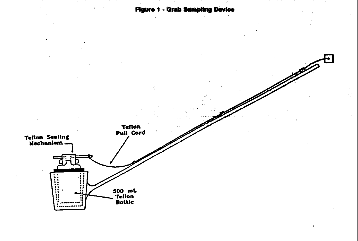
Method 1669
32 July 1996
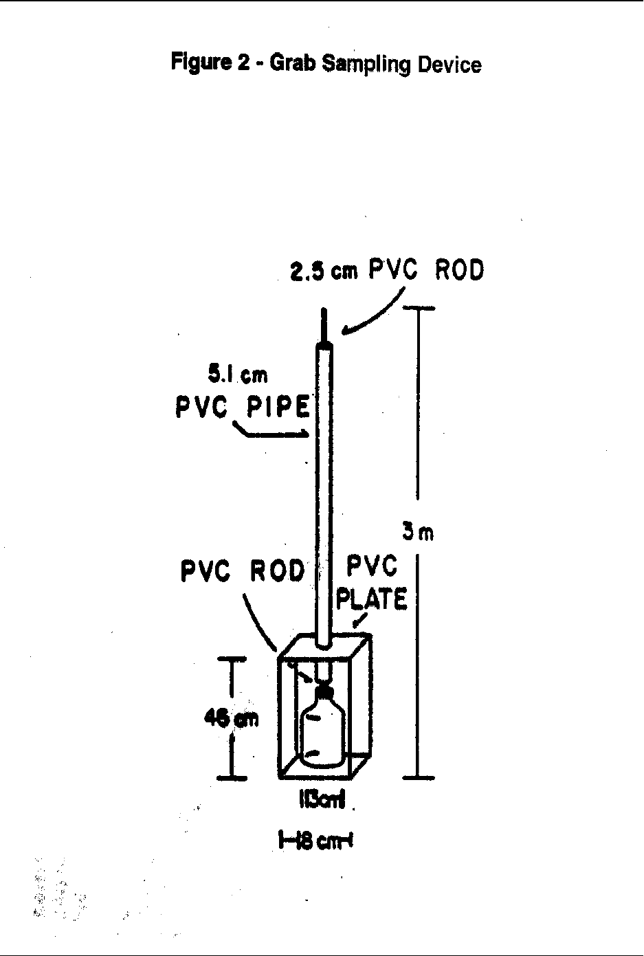
Method 1669
July 1996 33
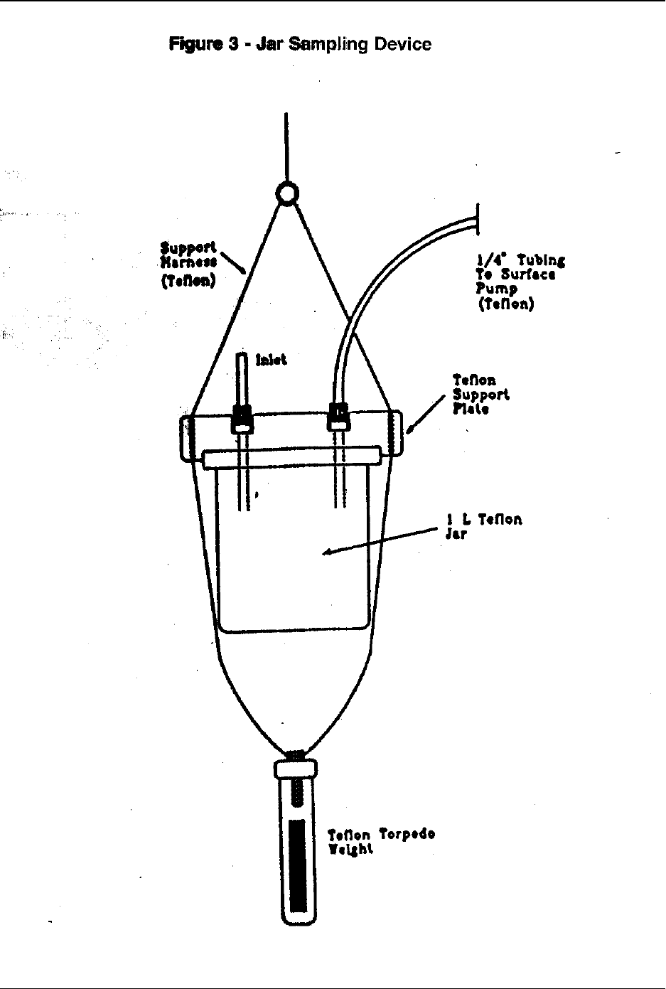
Method 1669
34 July 1996
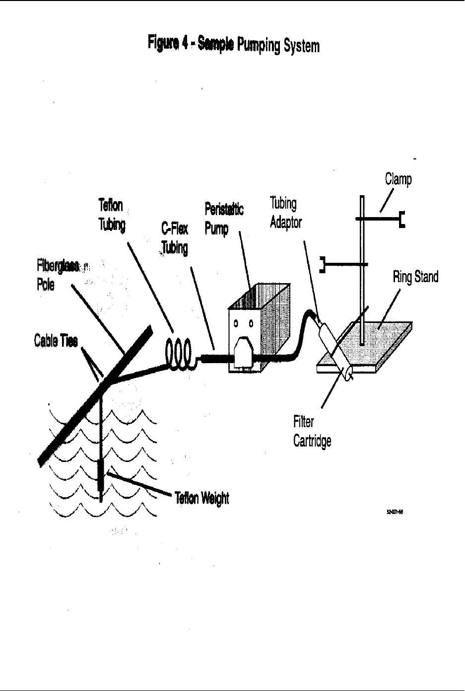
Method 1669
July 1996 35
