Savannah River Site Liquid Waste Planning Process
REVISION 21
January 2019
An Integrated System at the Savannah River Site
SRR-LWP-2009-00001
L
IQUID Waste
System Plan
Savannah River Remediation LLC
Savannah River Site
Aiken, SC 29808
Prepared for U.S. Department of Energy under Contract No. DE-AC09-09SR22505
SRR-LWP-2009-00001
REVISION: 21
January 31, 2019
KEYWORDS: Tank Farm, Salt Program
Saltstone, DWPF, Liquid Waste
SPF, SDF, ETP, Sludge Washing
Lifecycle, Waste Solidification
TCCR, MCU, ARP, CSSX, SWPF
RETENTION: PERMANENT
Liquid Waste System Plan
Revision 21
D. P. Chew
B. A. Hamm
M. N. Wells
Approvals:
__________________________________________
Thomas A. Foster
SRR President & Project Manager
__________________________________________
James L. Folk, Jr.
Assistant Manager for Waste Disposition
SRR-LWP-2009-00001 Liquid Waste System Plan
January 2019 Revision 21
Page ii
Authors
____________________________________________________________
D. P. Chew, System Planning
____________________________________________________________
B. A. Hamm, System Planning
____________________________________________________________
M. N. Wells, System Planning
Reviews
______________________________________________________________
P. J. Hill, Manager, System Planning

Liquid Waste System Plan SRR-LWP-2009-00001
Revision 21 January 2019
Page iii
Table of Contents
1. EXECUTIVE SUMMARY ............................................................................................................1
2. INTRODUCTION ........................................................................................................................4
2.1 COMMON GOALS & VALUES .......................................................................................................................... 4
2.2 SYSTEM PLANNING OVERVIEW ...................................................................................................................... 6
2.3 RISK ASSESSMENT .......................................................................................................................................... 7
3. PLANNING BASES .....................................................................................................................8
3.1 FUNDING ........................................................................................................................................................ 8
3.2 REGULATORY DRIVERS .................................................................................................................................. 8
3.3 REVISIONS ...................................................................................................................................................... 9
3.4 KEY MILESTONES ......................................................................................................................................... 10
4. PLANNING SUMMARY AND RESULTS .....................................................................................11
4.1 SLUDGE PROCESSING ................................................................................................................................... 11
4.2 DWPF OPERATIONS ..................................................................................................................................... 12
4.3 SALT PROCESSING ........................................................................................................................................ 13
4.3.1 Actinide Removal Process / Modular CSSX Unit (ARP/MCU) .................................................. 14
4.3.2 Tank Closure Cesium Removal (TCCR) ..................................................................................... 15
4.3.3 Salt Waste Processing Facility (SWPF) ..................................................................................... 16
4.4 SALTSTONE OPERATIONS ............................................................................................................................. 17
4.5 WASTE REMOVAL AND TANK CLOSURE ....................................................................................................... 18
4.5.1 Waste Removal and Tank Cleaning ............................................................................................ 18
4.5.2 Tank Operational Closure and Stabilization .............................................................................. 20
4.6 BASE OPERATIONS ....................................................................................................................................... 22
4.6.1 Supporting Nuclear Material Stabilization ................................................................................. 22
4.6.2 DWPF Recycle Handling ............................................................................................................ 22
4.6.3 Transfer Line Infrastructure ....................................................................................................... 23
4.6.4 Tank 48 Treatment ...................................................................................................................... 23
4.6.5 Effluent Treatment Project ......................................................................................................... 23
4.6.6 Managing Type III Tank Space ................................................................................................... 23
4.7 CLOSURE SEQUENCE FOR THE LIQUID WASTE SYSTEM ................................................................................ 24
5. DESCRIPTION OF ASSUMPTIONS AND BASES .........................................................................25
5.1 FUNDING ...................................................................................................................................................... 25
5.2 SALT WASTE DISPOSITION ........................................................................................................................... 25
5.3 SLUDGE PROCESSING ................................................................................................................................... 26
5.4 TANK CLOSURES .......................................................................................................................................... 26
5.5 TANK FARM OPERATIONS ............................................................................................................................ 27
5.6 ADDITIONAL TECHNICAL ASSUMPTIONS ...................................................................................................... 27
6. SYSTEM DESCRIPTION ...........................................................................................................30
6.1 HISTORY ....................................................................................................................................................... 30
6.2 TANK STORAGE ............................................................................................................................................ 30
6.3 WASTE TANK SPACE MANAGEMENT ............................................................................................................ 32
6.4 WASTE REMOVAL FROM TANKS ................................................................................................................... 33
6.5 SAFE DISPOSAL OF THE WASTE .................................................................................................................... 34
6.6 SALT PROCESSING ........................................................................................................................................ 34
6.7 SLUDGE PROCESSING ................................................................................................................................... 35
6.8 DWPF VITRIFICATION ................................................................................................................................. 35
6.9 SALTSTONE DISPOSITION ............................................................................................................................. 35
APPENDIX A—SALT SOLUTION PROCESSING ................................................................................40
APPENDIX B—TANK FARM INFLUENTS AND EFFLUENTS .............................................................41
APPENDIX C—BULK WASTE REMOVAL COMPLETE ......................................................................42
APPENDIX D—TANK REMOVAL FROM SERVICE ............................................................................43
APPENDIX E—LW SYSTEM PLAN—REVISION 21 SUMMARY ........................................................44

SRR-LWP-2009-00001 Liquid Waste System Plan
January 2019 Revision 21
Page iv
APPENDIX F—SLUDGE PROCESSING .............................................................................................45
APPENDIX G—GWSB UTILIZATION..............................................................................................46
APPENDIX H—CANISTER STORAGE ...............................................................................................48
APPENDIX I—TCCR COLUMNS INTERIM SAFE STORAGE .............................................................49
APPENDIX J—REMAINING TANK INVENTORY ................................................................................50
ACRONYMS ....................................................................................................................................51
REFERENCES ..................................................................................................................................53
Index of Tables
Table 1-1—Results of Modeled Cases ........................................................................................................................... 3
Table 3-1—Key Milestones ......................................................................................................................................... 10
Index of Figures
Figure 4-1—Sludge Feed Preparation ........................................................................................................................ 11
Figure 4-2—Double Stacking ...................................................................................................................................... 13
Figure 4-3—Schematic of the ARP/MCU Process ...................................................................................................... 14
Figure 4-4—Temporary Waste Removal ..................................................................................................................... 18
Figure 4-5—Drain, Add, Remove Method for Salt Waste Removal ............................................................................ 19
Figure 4-6—Mechanical Agitation Salt Removal ........................................................................................................ 19
Figure 4-7—Grout Placement ..................................................................................................................................... 21
Figure 4-8—Grouted Tank .......................................................................................................................................... 22
Figure 6-1—Waste Tank Composite Inventory (as of December 31, 2018) ................................................................ 32
Figure 6-2—Process Flowsheet .................................................................................................................................. 37
Figure 6-3—Liquid Waste Program—Current Status ................................................................................................. 38
Figure 6-4—Liquid Waste Process Overview.............................................................................................................. 39

Liquid Waste System Plan SRR-LWP-2009-00001
Revision 21 January 2019
Page 1 Executive Summary
1. Executive Summary
The last Liquid Waste System Plan, Revision 20
1
(LWSP–R20) was published in March 2016. This 21
st
Revision of the
Liquid Waste System Plan (hereinafter referred to as the Plan) documents a scenario to allow continued progress in
achieving the processing goals of the Department of Energy (DOE) at Savannah River Site (SRS) by Savannah River
Remediation (SRR). It assumes the conditions extant in the beginning of Fiscal Year (FY) 2019. It also assumes
continued 3H Evaporator operations as begun in mid-FY18. It further recognizes the outage for Melter replacement
and the Salt Waste Processing Facility (SWPF) tie-ins that resulted in the Defense Waste Processing Facility (DWPF)
resumption of operations in mid-FY18 with Modular Caustic Side Solvent Extraction (CSSX) Unit (MCU) operations
resuming shortly thereafter.
This Plan assumes aggressive performance of salt and sludge processing to forecast the best possible outcome for
dispositioning the waste in the SRS High Level Waste (HLW) tank farms. This optimistic case assumes receipt of the
funding required to: install removal equipment, process at stated rates, and maintain and replace (as necessary) the
equipment. It assumes no major equipment failures other than the Melter replacement. It also assumes no major changes
in safety requirements that would negatively affect the current planning basis for the removal, transfer, or processing
of waste. As described in the Risk and Opportunity Management Plan
2
(ROMP), there are several risk events that, were
they realized, could adversely affect the successful completion of the program goals in the time described.
The 3H Evaporator (242-25H) is required to volume reduce sludge wash decants and heel removal waste. In February
2016, however, waste was discovered in the 3H Evaporator cell having leaked from the evaporator vessel. In March
2017, the anomaly and failure mechanism were identified, and a path forward developed resulting in the resumption of
operations in July 2018.
In February 2017, the second DWPF Melter was declared to have reached its End-of-Life (EOL) after fourteen years
of operations, greatly exceeding its design life with more than double the life of the first melter. Melter replacement
necessitated interruption of DWPF and MCU processing. Planned outages to make physical tie-ins for SWPF were
accelerated to coincide with the melter replacement outage. These outage-related tie-ins were completed, the melter
replaced, and DWPF operations resumed in December 2017.
One other feature of this Plan is incorporation of the provisions of the “Agreement”
3
executed in October 2016. That
“Agreement” designates specific technology incorporation (i.e., Tank Closure Cesium Removal [TCCR], Next
Generation Solvent [NGS] in SWPF, and Sonar mapping demonstration) into the LW disposition matrix. Salt
processing goals and deadlines are identified. Along with the goals and timing is a recognition of the challenges of
operating a complex set of interdependent facilities, many of which are older such that documentation of force majeure
events is allowed.
This Plan results in processing over 25 million gallons (Mgal) of salt waste in the “Agreement” period of FY16 through
FY22. In addition to the 4,173 canisters that have been produced from FY96 through FY18, an additional 3,948 cans
are projected for a total production of approximately 8,121 DWPF canisters over the lifetime of the project.
The completion of waste removal in F-Tank Farm (FTF), in this Plan, occurs in 2031 allowing the Inter-Area Line to
be shut down also in 2031 and FTF closures complete by the end of 2033. LW treatment and disposition in DWPF and
SWPF are completed by 2034. Of the 51 tanks, 44 tanks are closed by 2035 and the last of the H-Tank Farm (HTF)
tanks, the DWPF feed tank, is closed in 2037.
Purpose
The purpose of this Plan is to integrate and document the activities required to disposition the existing and future HLW
and remove from service radioactive LW tanks and facilities belonging to DOE at SRS (DOE-SR). It records a planning
basis for waste processing in the LW System through the end of the program mission.
This twenty-first revision (Revision 21) of the Plan:
Supports input to development of financial submissions to the complex-wide Integrated Planning,
Accountability, & Budgeting System (IPABS)
Provides a technical basis for LW Contract and Contract Performance Baseline changes
Provides input to the development of regulatory agreements
Common Goals & Values
The overarching principles which govern strategic planning and execution of the SRS Liquid Waste Disposition
Program are summarized in the seven “Common Goals and Values” that were agreed upon by key stakeholders over

SRR-LWP-2009-00001 Liquid Waste System Plan
January 2019 Revision 21
Executive Summary Page 2
a decade ago (cf. Progress in Implementation of Common Goals and Values
4)
. These remain the guiding goals and
values for program execution and planning:
1. Reduce operational risk and the risk of leaks to the environment by removing waste from tanks and closing
the tanks.
2. Remove actinides from waste expeditiously since their impact on the environment is the most significant if a
leak occurs.
3. Maximize amount of waste ready for disposal in deep geologic repository. Make significant effort to ensure
maximum amount of long-lived radionuclides are disposed in a deep geologic repository.
4. Remove as much cesium as practical from salt waste and dispose in parallel with vitrified sludge.
5. Dispose of cesium as soon as practical to avoid having cesium only waste when sludge vitrification is complete.
6. Limit disposal of radioactive waste onsite at SRS so that residual radioactivity is as low as reasonably
achievable.
7. Ensure DOE’s strategy and plans are subject to public involvement and acceptance.
Goals
The goals of previous revisions of this Plan, through Revision 17, were to meet Federal Facility Agreement (FFA)
5
and Site Treatment Plan (STP)
6
regulatory commitments. However, with the delays of SWPF beyond October 2014, as
demonstrated in Revision 17, the following regulatory commitments have been adversely affected:
● Meet tank waste removal regulatory milestones in the currently-approved FFA
● Meet tank removal-from-service regulatory milestones in the currently-approved FFA
● Meet the waste treatment goals identified in the STP.
The goals (not necessarily the outcomes) of this Plan were to meet the following programmatic objectives:
1. Continual safe storage of liquid waste in tanks and vitrified canisters in storage.
2. Complete LW System operational closure by the end of FY33.
3. Complete operational closure of F Tank Farm by end of FY28.
4. Process liquid salt waste (e.g., dissolved salt solution, supernate) in FY16 through FY22 in accordance with
the South Carolina Department of Health and Environmental Control (SCDHEC) Dispute Resolution
Agreement for Alleged Violations of Class 3 Industrial Solid Waste Landfill Permit Facility, Facility ID
#025500-1603
3
(referred to hereinafter as the “Agreement”) (including consideration for Force Majeure
conditions).
5. Remove the bulk of the waste in the Older Style H-Tank Farm tanks in the water table (i.e., Tanks 9, 10, 13,
14) by end of FY23.
6. Complete operational closure of the 1F Evaporator by the end of FY23.
Please note that some of these goals were not achievable within the constraints of the Plan.
Additional principles guiding the development of this Plan include:
● Conduct operations consistent with the Waste Determinations (WD): Section 3116 Determination for Salt
Waste Disposal at the Savannah River Site
7
, the Basis for Section 3116 Determination for Salt Waste Disposal
at the Savannah River Site
8
, the Section 3116 Determination for Closure of F-Tank Farm at the Savannah River
Site
9
, the Basis for Section 3116 Determination for Closure of F-Tank Farm at the Savannah River Site
10
, the
Section 3116 Determination for Closure of H-Tank Farm at the Savannah River Site
11
, and the Basis for Section
3116 Determination for Closure of H-Tank Farm at the Savannah River Site
12
● Comply with applicable permits and consent orders, including the Modified Class 3 Landfill Permit for the
SRS Z-Area Saltstone Disposal Facility (SDF) (permit ID 025500-1603) and State-approved Consolidated
General Closure Plan
13
(GCP)
● Minimize the quantity of radionuclides (as measured in curies) dispositioned in the SDF, keeping the total
curies at or below the amount identified in Savannah River Site – Liquid Waste Disposition Processing
Strategy
14
(SRS LW Strategy), as amended by letter from the SCDHEC to DOE-SR
15
and the Basis for Section
3116 Determination for Salt Waste Disposal at the Savannah River Site
8
and the “Agreement”
● Support continued nuclear material stabilization of legacy materials in H-Canyon.
To enable continuation of risk reduction initiatives encompassed by the goals above, this Plan follows a processing
strategy to provide the tank space required to support meeting, or minimizing impacts to meeting, programmatic
objectives. During the period prior to startup of SWPF in 2020, near-term retrieval, treatment, and disposal of salt waste
are required. The ARP/MCU facilities provide this treatment. Operation of these salt treatment processes frees up
working space in the 2H and 3H Evaporators’ concentrate receipt tanks (Tanks 38, 30, and 37). This provides support
Liquid Waste System Plan SRR-LWP-2009-00001
Revision 21 January 2019
Page 3 Executive Summary
for near-term handling of waste streams generated from tank removals from service, DWPF sludge batch (SB)
preparation, DWPF recycle handling, and H-Canyon processing.
Revisions
The significant updates from the previous version of this Plan, the Liquid Waste System Plan, Revision 20
1
, include:
● Major Equipment:
— Resolution of 3H Evaporator Pot leak and return to service
— Replacement of DWPF EOL Melter 2
● Salt Processing:
— SWPF startup moved to March 2020 from December 2018
— Plan for installation of two TCCR units
● DWPF:
— Resolve Hydrogen Generation Rate (HGR) Potential Inadequacy in Safety Analysis (PISA)
— Convert to Glycolic Flowsheet
Results of the Plan
Table 1-1—Results of Modeled Cases describes the major results as compared to Revision 20 of the Plan:
Table 1-1—Results of Modeled Cases
Parameter
Rev 20,
Case 1 Rev 21,
Date SWPF be
g
ins hot commissionin
g
Dec 2018 March 2020
Date last LW facilit
y
turned over to D&D 2041 2037
Final T
y
pe I and II tanks complete operational closure 2033 2030
Complete
b
ulk slud
g
e treatmen
t
2031 2031
Complete bulk salt treatment 2032 2031
Complete heel treatmen
t
2036 2034
TCCR for supplemental salt waste treatmen
t
1 uni
t
2 units
N
ext
g
eneration solvent for increased SWPF throu
g
hpu
t
Jan 2022 Ma
y
2021
Total number of canisters
p
roduce
d
8,170
8,121
Year supplemental canister stora
g
e required to be read
y
2029 2030
Radionuclides (curies) dispositioned in SDF within the
amended SRS LW Strate
gy
Yes Yes
Total number of SDUs 14 13
Operational Closure: Supplemental salt processing via TCCR, as well as a quicker ramp up to the SWPF rate of 9
Mgal/yr, accelerates closure of old-style tanks with respect to Rev 20
SWPF Processing: This Plan assumes SWPF will implement NGS by the beginning of the second year of operation
with no impact to the program schedule; the 9 Mgal/yr processing rate will be available after implementation of
Enhanced Low Activity Waste Disposal and 24/7 shift operation at the Saltstone Production Facility (SPF)
Radionuclides Dispositioned in SDF: This Plan is consistent with SRS LW Strategy
as amended by letter from the
SCDHEC to DOE-SR
15
and the Basis for Section 3116 Determination for Salt Waste Disposal at the Savannah River
Site
8
concerning the total curies dispositioned at SDF.
Supporting Nuclear Material Stabilization: The Tank Farms have assumed receipt space of 200 thousand gallons
(kgal) per year of H-Canyon waste through FY22 increasing to 300 kgal/yr from FY23 through FY30. Additionally,
this Plan accommodates receipt of particular H-Canyon waste streams in Tank 50 or directly to sludge batches through
FY30. (Note: after FY30, any H-Canyon waste will be dispositioned by H-Canyon)
Canister Storage: With the continued modification of Glass Waste Storage Building (GWSB) 1 to enable stacking
two canisters in each storage location, this Plan forecasts the need for supplemental canister storage beginning in FY30.
Shipment of canisters from SRS is not included in this Plan since a federal repository has yet to be identified.
Saltstone Disposal Units (SDU): SDU-2, SDU-3, and SDU-5 are dual cylindrical cell units with ~2.8 Mgal grout
capacity (~1.6 Mgal of feed) per cell. SDU-2 and SDU-5 are filled. SDU-6 (currently in use) is a single cylindrical cell
unit with ~32 Mgal grout capacity (~17 Mgal of feed). This Plan assumes future SDUs will have the same capacity as
SDU-6. The last SDU will be sized as needed to complete the LW mission.

SRR-LWP-2009-00001 Liquid Waste System Plan
January 2019 Revision 21
Introduction Page 4
2. Introduction
This twenty-first revision of the Liquid Waste System Plan documents a strategy to operate the LW System at SRS to
receive, store, treat, and dispose of radioactive LW and to close waste storage and processing facilities. The LW System
is a highly integrated operation involving safely storing LW in underground storage tanks; removing, treating, and
dispositioning the low-level waste (LLW) fraction in concrete SDUs; vitrifying the higher activity waste at DWPF; and
storing the vitrified waste in stainless steel canisters pending permanent disposition. After waste removal and
processing, the storage and processing facilities are cleaned and closed. This Plan assumes the reader has a familiarity
with the systems and processes discussed. Section 6—System Description of this Plan provides an overview of the LW
System.
The Tank Farms have received over 160 million gallons of waste from 1954 to the present. Having reduced the volume
of waste via evaporation and dispositioned waste via vitrification and saltstone, the Tank Farms currently store
approximately 35 million gallons of waste containing approximately 248 million curies (MCi) of radioactivity. As of
December 31, 2018, DWPF had produced 4,179 vitrified waste canisters. (Note: All volumes and curies reported as
current inventory in the Tank Farms are as of December 31, 2018 and account for any changes of volume or curies in
the Tank Farms since Revision 20 of the Plan and the Section 3116 Determination for Salt Waste Disposal at the
Savannah River Site
7
.)
Successful and timely salt waste removal and disposal is integral to efforts to proceed with all aspects of tank cleanup
and removal from service, extending well beyond permitted disposal of the solidified low-activity salt waste streams
themselves. Removal of salt waste enables some tanks to be removed from service in anticipation of future closure. It
also is necessary for the continued removal and stabilization of the high-activity sludge fraction of the waste. Preparing
the sludge for processing in DWPF generates salt waste which must be stored or dispositioned. Operating ARP/MCU
reduces the volume of stored salt waste and enhances salt waste processing so that vitrification of the sludge can
continue more efficiently. Operating ARP/MCU also supports conversion of some tanks from storage to preparation of
salt batches for processing in.
This Plan forecasts the best possible outcome for dispositioning the waste in the SRS tank farms via optimistic
operation of waste removal, ARP/MCU, TCCR, SWPF, DWPF, and the Saltstone facilities. This optimistic case
assumes timely receipt of the funding required to: install waste removal equipment, process at stated rates, and maintain
and replace equipment, as necessary. It assumes no major equipment failures other than the one Melter replacement. It
also assumes no major changes in safety requirements that would negatively affect the current planning basis for the
storage, removal, transfer, or processing of waste. As described in the ROMP, there are several risk events that, were
they realized, could adversely affect the successful completion of the program goals in the time described.
2.1 Common Goals & Values
The overarching principles which govern strategic planning and execution of the SRS Liquid Waste Disposition
Program are summarized well in the seven “Common Goals and Values” that were agreed upon by key stakeholders
over a decade ago
4
. These remain the guiding goals and values for program execution and planning:
1. Reduce operational risk and the risk of leaks to the environment by removing waste from tanks, and
closing the tanks
Curie Workoff from ~550 MCi in 1995 to 248 MCi at the end of 2018 (dispositioning ~61 MCi in glass, 0.5
MCi in Saltstone grout, and the remainder due to radioactive decay).
Of the 14 SRS tanks with leakage history (all old-style tanks):
— 6 are operationally closed and grouted (Tanks 5, 6, 12, 16, 19, and 20)
— 2 are supporting the TCCR process (Tanks 10 and 11)
— 1 is awaiting heel removal activities to commence (Tank 15)
— 3 contain essentially dry waste, with little or no free liquid supernate (Tanks 1, 9, and 14)
— 2 contain liquid supernate at a level below known leak sites (Tanks 4 and 13)
● Of the 24 SRS old-style tanks:
— 8 are grouted and operationally closed (Tanks 5, 6, 12, 16, 17, 18, 19, and 20)
— 5 have had bulk waste removal completed (Tanks 4, 7, 8, 11, and 15)
● Approximately 66% of old-style tank space is currently empty or grouted and approximately 23% of new-style
tank space is empty.

Liquid Waste System Plan SRR-LWP-2009-00001
Revision 21 January 2019
Page 5 Introduction
2. Remove actinides (sludge) from waste expeditiously since they affect the environment most significantly if
a leak occurs.
● Actinides and other high activity components are being immobilized in glass
● To date, over 4,170 canisters of waste (~51 % of the projected lifecycle total) have been vitrified
● Canister waste loading was raised from the originally planned ~28%, as appropriate
● In August 2013, DWPF set a production record of 40 canisters produced in a single month.
3. Maximize amount of waste ready for disposal in deep geologic repository. Make significant effort to ensure
maximum amount of long-lived radionuclides are disposed in a deep geologic repository.
● To date, over 98% of the curies immobilized have been placed in glass in preparation for disposal in a deep
geologic repository
● At mission completion, over 99% of treated curies are projected to have been immobilized in glass.
4. Remove as much cesium as practical from salt waste and dispose in parallel with vitrified sludge.
● A small portion of salt waste (~2%) was treated only via Deliquification, Dissolution, and Adjustment (DDA)
● Extraction of cesium from salt waste through ARP/MCU began in 2008 and, through 2013, was ~10 times
more efficient than the original projection (~3.4% of forecast salt production)
● Deployment of NGS at MCU in 2014 improved cesium removal efficiency by more than 200 times, exceeding
the original SWPF design; the cesium-laden MCU Strip Effluent (SE) stream is vitrified with sludge and
disposed in canisters (~2.8% of forecast salt production)
● TCCR is forecast to provide supplemental treatment capability to existing and future salt processing and
improve confidence in supporting the desired acceleration of waste retrieval and tank operational closure efforts
(~16%)
● SWPF is forecast to treat the highest volume (~ 75%) and activity of the salt waste.
5. Dispose of cesium as soon as practical to avoid having cesium only waste when sludge vitrification is
complete.
● To date, over 9.8 million gallons (Mgal) of salt waste (approximately 8.4% of the projected lifecycle total)
have been treated and dispositioned
● Allocation of available resources is focused on maintaining the pace of risk reduction through waste treatment
and immobilization
● The contribution of ARP/MCU was enhanced by deploying NGS to increase cesium removal efficiency
● This Plan utilizes TCCR to supplement SWPF to accelerate salt processing
● This Plan forecasts completion of salt processing prior to completion of sludge processing.
6. Limit disposal of radioactive waste onsite at SRS so that residual radioactivity is as low as reasonably
achievable.
● Formal Performance Assessments (PA) of LLW disposal and operationa
l closure of tanks, coupled with cost
to benefit evaluations prior to cessation of tank waste removal activities, support that any residual future
impacts from onsite waste disposal are within the requirements of applicable federal and state laws and
regulations, and are as low as reasonably practical
● Based on operational experience, over 95% of the radioactive inventory in a tank has been removed after bulk
waste removal and heel dilution; over 99% of the radioactive inventory has been removed after final cleaning
● At mission completion, over 99% of treated curies are projected to have been immobilized in glass and
packaged for offsite disposal in a deep geologic repository
● The originally agreed upon projection for onsite emplacement in engineered disposal units from LW treatment
and disposition was 3 MCi (2.5 MCi from DDA-only; 0.3 MCi from ARP/MCU; and 0.2 MCi from SWPF).
That agreement was reduced to 0.8 MCi in August 2011
15
based on progress as of 2011.
7. Ensure DOE’s strategy and plans are subject to public involvement and acceptance.
● The formal processes for evaluation, determination, and execution of all tank waste removal, disposal, and
operational closure fully involves SCDHEC, the Environmental Protection Agency (EPA), and the Nuclear
Regulatory Commission (NRC)
● Various formal hold points exist in these processes for public involvement and comment
● All SRS LW disposition activities fall within the purview of the Defense Nuclear Facilities Safety Board
(DNFSB) oversight, and DNFSB periodically issues publicly accessible reports of their evaluations and
conducts periodic meetings to receive public input regarding their activities
● The SRS Citizen’s Advisory Board receives routine updates in a public venue regarding all SRS LW
Disposition activities
● Updates to this Plan are provided to all regulatory and oversight entities and made available for public review

SRR-LWP-2009-00001 Liquid Waste System Plan
January 2019 Revision 21
Introduction Page 6
● Quarterly updates of radiological inventory additions to SDUs are posted to a publicly accessible website
● SRR monthly and annual reports of progress towards disposition of SRS LW are available to the public.
2.2 System Planning Overview
System Plan Rev. 21 Goals and Priorities
DOE’s overarching priorities for development of this Plan are:
1. Continual safe storage of liquid waste in tanks and vitrified canisters in storage.
2. Complete LW System operational closure by the end of FY33.
3. Complete operational closure of F Tank Farm by end of FY28.
4. Process liquid salt waste (e.g., dissolved salt solution, supernate) in FY16 through FY22 in accordance with
the SCDHEC “Agreement”
3
(including consideration for Force Majeure conditions).
5. Remove the bulk of the waste in the old-style H-Tank Farm tanks in the water table (i.e., Tanks 9, 10, 13,
14) by end of FY23.
6. Complete operational closure of the 1F Evaporator by the end of FY23.
Please note that some of these goals were not achievable within the constraints of the Plan.
Constraints
Operations are planned within the boundaries established by applicable regulatory constraints and processing
constraints. For more information regarding regulatory constraints, refer to Section 3.2.
Processing constraints are primarily addressed within the context of tank space management.
There is currently a premium on processing and storage space in the SRS radioactive LW tanks. Space is needed for
safe storage of waste; volume reduction initiatives via evaporation; retrieval of waste from old-style tanks and
subsequent cleaning of those emptied tanks; preparation of sludge and dissolution of salt prior to treatment in
downstream facilities; and receipt of influent wastes from both DWPF and H Canyon. The Tank Farm space
management strategy is based on a set of key assumptions involving projections of treatment facility throughput, Tank
Farm evaporator performance, and influent stream volumes.
As the Liquid Waste program proceeds, the roles of some tanks will change to maximize efficient use of available space
at that time. Currently, the 27 new-style tanks are deployed as follows:
● 5 (Tanks 38, 41, 43, 49, and 50) are dedicated to salt batching, qualification, and disposition (including DWPF
recycle beneficial reuse, feeding the Saltstone Production Facility (SPF), and the 2H Evaporator);
● 2 additional tanks (Tanks 27 and 42) are planned for conversion to salt blend tanks to prepare salt batching
● 6 (Tanks 29, 30, 32, 37, 40, and 51) are dedicated to sludge batching, qualification, and disposition (including
the 3H Evaporator)
● 1 (Tank 39) supports uninterrupted H-Canyon waste receipts
● 13 (Tanks 25, 26, 28, 31, 33, 34, 35, 36, 44, 45, 46, 47, and 48) are dedicated to safe storage of legacy LW
pending retrieval and disposition.
These 27 new-style tanks represent a maximum storage capacity of 35 million gallons of space. However, not all that
space is available for waste storage:
● 3.0 Mgal is margin as defense-in-depth operational control coupled with Safety Class or Safety Significant
(SC/SS) structures, systems, or components (SSC) to facilitate reasonably conservative assurance of more than
adequate dilution and ventilation of potentially flammable vapors
● 1.3 Mgal is procedurally-required minimum contingency space for recovery from the unlikely event of a large
waste leak elsewhere in the system
● 3.9 Mgal is operational “working” space variously used to provide:
— Additional contingency transfer space as operational excess margin above the procedurally-required
minimum
— Excess margin to preserve salt batch quality and maintain uninterrupted treatment and disposition through
ARP/MCU and Saltstone
— Excess margin to preserve sludge batch quality and maintain uninterrupted immobilization through DWPF
— Excess margin to preserve uninterrupted support for H-Canyon.

Liquid Waste System Plan SRR-LWP-2009-00001
Revision 21 January 2019
Page 7 Introduction
2.3 Risk Assessment
The PBS-SR-0014, Radioactive Liquid Tank Waste Stabilization and Disposition, Risk and Opportunity Management
Plan (ROMP) documents the comprehensive identification and analysis of technical risks and opportunities associated
with the LW program. It identifies individual technical and programmatic risks and presents the strategies for handling
risks and opportunities in the near-term and outyears.
The ROMP identifies over 100 risks associated with this Plan with a total outyear Technical and Programmatic Risk
Assessment (T&PRA) of several billion dollars. After mitigation, overall risk level is reduced; however, some concerns
remain:
● Funding—Adequate funding for PBS-SR-0014 throughout its life cycle to permit full execution of the System
Plan is uncertain. This is a crosscutting risk for both major contractors at SRS and is addressed at the site level.
● Aging Infrastructure—The System Plan end date places significant stress on what will be an increasingly aging
infrastructure. Recent infrastructure failures, such as the leak in the 3H Evaporator pot, provide insight into the
problems that may be encountered with operating the HLW System for an additional 18 years.
● TCCR Spent Column Disposition—TCCR is forecast to produce over 120 cesium-laden ion exchange columns
over the course of its mission. Interim Safe Storage (ISS) will be provided on-site for these columns, but the
final disposition for these highly radioactive columns has not been selected.
● Infrastructure Capacity—The capacity of the existing Tank Farm infrastructure will be stretched close to its
limits in supporting salt batch preparation. Choke points could easily be encountered if multiple use conflicts
develop and planned availability of transfer routes and equipment are impacted.
● Emergent Changes to Requirements—Changes to Business, Project Management, or Technical requirements
may adversely affect plans for the provision of necessary facilities (e.g., SDUs), or performance of necessary
activities (e.g., transfers). This has the potential to interfere with normal operational expectations assumed in
the Plan.
● DWPF Recycle—For every 1.0 gallon of sludge treated in DWPF, 1.3 gallons of dilute salt waste is returned
to the Tank Farm. This System Plan assumes that in FY23, the DWPF recycle stream will be diverted for
treatment outside of the Tank Farm, but a specific treatment path has not yet been selected.

SRR-LWP-2009-00001 Liquid Waste System Plan
January 2019 Revision 21
Planning Bases Page 8
3. Planning Bases
This Plan is based on DOE-SR and SRR agreed inputs, assumptions, and priorities. Dates, volumes, and chemical or
radiological composition information contained in this Plan are planning approximations only. Specific flowsheets
guide actual execution of individual processing steps. The activities described are summary-level activities, some of
which have yet to be fully defined. The sequence of activities reflects the best judgment of the planners. The individual
activity execution strategies contain full scope, schedule, and funding development. Upon approval of scope, cost, and
schedule baselines; modifications of this Plan may be required.
3.1 Funding
Progress toward the ultimate goal of immobilizing all the LW at SRS is highly dependent on available funding. This
Plan was developed assuming the availability of the funding required as specified in the inputs and assumptions
referenced above. It supports justification for requesting necessary funding profiles. With any reduction from full
funding, activities that ensure safe storage of waste claim priority. Funding above that required for safe storage enables
risk reduction activities, i.e., waste removal, treatment—including immobilization—and removal from service, as
described in this Plan.
3.2 Regulatory Drivers
Numerous laws, constraints, and commitments influence LW System planning. Described below are requirements most
directly affecting LW system planning. This Plan assumes the timely acquisition of regulatory approvals.
South Carolina Environmental Laws
Under the South Carolina Pollution Control Act, S.C. Code Ann. §§ 48-1-10 et seq., SCDHEC is the delegated authority
for air pollution control and water pollution control. The State has empowered SCDHEC to adopt standards for
protection of water and air quality, and to issue permits for pollutant discharges. Further, SCDHEC is authorized to
administer both the federal Clean Water Act and the Clean Air Act. Under South Carolina’s Hazardous Waste
Management Act, S.C. Code Ann. §§ 44-56-10 et seq., SCDHEC is granted the authority to manage hazardous wastes.
With minor modifications, SCDHEC has promulgated the federal Resource Conservation and Recovery Act (RCRA)
requirements, including essentially the same numbering system. The South Carolina Solid Waste Policy and
Management Act, S.C. Code Ann. §§ 44-96-10 et seq., provides standards for the management of most solid wastes in
the state. For example, SCDHEC issued to DOE-SR permits such as the Class 3 Landfill Permit for SDF. This landfill
permit contains conditions for the acceptable disposal of non-hazardous waste in the SDF. This permit also contains
provisions for fines and penalties. Other principal permits required to operate LW facilities pursuant to the state’s
environmental laws include:
● SCDHEC Bureau of Water:
— Industrial wastewater treatment facility permits (e.g., Tank Farms, DWPF, ARP/MCU, Effluent Treatment
Project [ETP], and the SPF)
— National Pollutant Discharge Elimination System (NPDES) permit (H-16 Outfall discharges from ETP)
● SCDHEC Bureau of Air Quality:
— Part 70 Air Quality Permit (one Site-wide Air Permit including the LW facilities).
Site Treatment Plan (STP)
The STP
6
for SRS describes the development of treatment capacities and technologies for mixed wastes and provides
guidance on establishing treatment technologies for newly identified mixed wastes. The STP allows DOE, regulatory
agencies, the States, and other stakeholders to efficiently plan mixed waste treatment and disposal by considering waste
volumes and treatment capacities on a national scale. The STP identifies vitrification in DWPF as the preferred
treatment option for appropriate SRS liquid high-level radioactive waste streams and solidification in Saltstone for low-
level radioactive waste streams. In 1996, SRS committed that:
“Upon the beginning of full operations, DWPF will maintain canister production sufficient to meet
the commitment for the removal of the backlogged and currently generated waste inventory by
2028.”
The commitment for the removal of the waste by 2028 encompasses bulk waste removal and heel removal scope of
this Plan. Final cleaning, deactivation, and removal from service of storage and processing facilities are subsequent to
the satisfaction of this commitment. Note that with the changes in technology and challenges in implementing the
various technologies this Plan does not meet this commitment, even with additional salt processing.

Liquid Waste System Plan SRR-LWP-2009-00001
Revision 21 January 2019
Page 9 Planning Bases
Federal Facility Agreement (FFA)
The EPA, DOE, and SCDHEC executed the SRS FFA
5
on January 15, 1993, with an effective date of August 16, 1993.
It provides standards for secondary containment, requirements for responding to leaks, and provisions for the removal
from service of leaking or unsuitable LW storage tanks. Tanks scheduled for operational closure may continue to be
used but must adhere to the FFA schedule for operational closure and the applicable requirements contained in the Tank
Farms’ industrial wastewater treatment facility permit. Several agreements since then have modified the original
agreement recognizing the realization of previously identified risks (e.g., delays in SWPF start-up date).
National Environmental Policy Act
The National Environmental Policy Act (NEPA) requires federal agencies to assess the potential environmental impacts
of proposed actions. Seven existing NEPA documents and their associated records of decision directly affect the LW
System and support the operating scenario described in this Plan:
● DWPF Supplemental Environmental Impact Statement (SEIS) (DOE/EIS-0082-S)
● Final Waste Management Programmatic Environmental Impact Statement (PEIS) (DOE/EIS-0200-F)
● SRS Waste Management Final Environmental Impact Statement (EIS) (DOE/EIS-0217)
● Interim Management of Nuclear Materials EIS (DOE/EIS-0220)
● SRS High-Level Waste Tank Closure Final EIS (DOE/EIS-0303)
● Environmental Assessment (EA) for the Closure of the HLW Tanks in F- and H Areas at SRS (DOE/EA-1164)
● SRS Salt Processing Alternatives Final SEIS (DOE/EIS-0082-S2).
Ronald W. Reagan National Defense Authorization Act for Fiscal Year 2005
The Ronald W. Reagan National Defense Authorization Act for Fiscal Year 2005 (NDAA) Section 3116 (NDAA
§3116) allows determinations by the Secretary of Energy, in consultation with the NRC, that certain radioactive waste
from reprocessing is not high-level waste and may be disposed of in South Carolina pursuant to a State-approved
closure plan or State-issued permit. For salt waste, DOE contemplates removing targeted fission products and actinides
using a variety of technologies and combining the removed fission products and actinides with the metals being vitrified
in DWPF. NDAA §3116 governs solidifying the remaining low-activity salt stream into saltstone for disposal in the
SDF. For tank removal from service activities, NDAA §3116 governs the Waste Determinations for the Tank Farms
that demonstrate that the tank residuals, the tanks, and ancillary equipment (evaporators, diversion boxes, etc.) at the
time of removal from service and stabilization can be managed as non-high-level waste.
Conduct of operations are planned in accordance with the following applicable portions of the NDAA:
● Section 3116 Determination for Salt Waste Disposal at the Savannah River Site
7
● Basis for Section 3116 Determination for Salt Waste Disposal at the Savannah River Site
8
● Section 3116 Determination for Closure of F-Tank Farm at the Savannah River Site
9
● Basis for Section 3116 Determination for Closure of F-Tank Farm at the Savannah River Site
10
● Section 3116 Determination for Closure of H-Tank Farm at the Savannah River Site
11
● Basis for Section 3116 Determination for Closure of H-Tank Farm at the Savannah River Site
12
3.3 Revisions
The significant updates from the previous version of this Plan, the Liquid Waste System Plan, Revision 20
1
, include:
● Major Equipment:
— Resolution of 3H Evaporator Pot leak and return to service
— Replacement of DWPF EOL Melter 2
● Salt Processing:
— SWPF startup moved to March 2020 from December 2018
— SWPF early year production rates are increased
— Plan for installation of two TCCR units
● DWPF:
— Resolve HGR PISA
— Convert to Glycolic Flowsheet

SRR-LWP-2009-00001 Liquid Waste System Plan
January 2019 Revision 21
Planning Bases Page 10
3.4 Key Milestones
Key Milestones are those major dates deemed necessary under this Plan to remove waste from storage, process it into
glass or saltstone, and close the LW facilities. The LW System Plan, Revision 20 milestones are provided for
comparison.
Table 3-1—Key Milestones
Key Milestone Rev 20 Case 1 Rev 21
Date SWPF be
g
ins hot commissionin
g
Dec 2018 March 2020
Date last LW facilit
y
turned over to D&D 2041 2037
Final T
y
pe I, II, and IV tanks complete operational closure 2036 2033
Complete bulk slud
g
e treatmen
t
2031 2031
Complete bul
k
salt treatment 2032 2031
Complete heel treatmen
t
2036 2034
Total number of canisters produce
d
8,170 8,121
Year supplemental canister stora
g
e required to be read
y
2029 2030
Initiate ARP/MCU Processin
g
(actual)
A
pr 2008
A
pr 2008
Initiate TCCR Processin
g
2018 2019
Initiate SWPF Processin
g
Dec 2018 Ma
y
2020
–
Salt Solution Processed via DDA-
s
olel
y
(actual) 2.8 M
g
al 2.8 M
g
al
–
Salt Solution Processed via ARP/MCU 10
Mg
al 8.1
Mg
al
–
Salt Solution Processed via TCCR 0.8
Mg
al 16.8
Mg
al
–
Salt Solution Processed via SWPF 110
Mg
al 90
Mg
al
N
umber of SDU 14 13
Operational Closure: Supplemental salt processing via TCCR accelerates closure of old-style tanks with respect to
Rev 20.
SWPF Processing: Hot commissioning begins in March 2020 with the deliberate introduction of radioactive materials
into the several subprocesses of SWPF for two months. Beginning in the third month (May 2020) operations begin with
a forecast capacity of 6 Mgal/year. The second year of operations is forecast to begin the 9 Mgal/yr operations through
the end of the program, except for major process interruptions e.g., the planned DWPF Melter change outage in 2029.
Vitrification of Sludge at DWPF: This Plan forecasts completion of salt processing concurrent with sludge
processing, minimizing sludge simulant addition. Processing of the remaining heels will continue past the end of SWPF
operations.
Canister Storage: This Plan recognizes the continued modification of GWSB 1 to allow storage of two canisters in
each storage position. GWSB 1 and 2 are forecast to be full in 2029 requiring provision of supplemental canister storage
beginning in FY30. Shipment of canisters from SRS is not included in this Plan since a federal repository has not yet
been identified.
Saltstone Disposal Units (SDU): SDU-2, SDU-3, and SDU-5 are dual cylindrical cell units with ~2.8 Mgal grout
capacity (~1.6 Mgal of feed) per cell. SDU-2 and SDU-5 are filled. SDU-6 (currently in use) is a single cylindrical cell
unit with ~32 Mgal grout capacity (~17 Mgal of feed). This Plan assumes future SDUs will have the same capacity as
SDU-6. The last SDU will be sized as needed to complete the LW mission.
Liquid Waste System Plan SRR-LWP-2009-00001
Revision 21 January 2019
Page 11 Planning Summary and Results
4. Planning Summary and Results
This section summarizes the key attributes of this Plan. Detailed discussion on risks and associated mitigation strategies
are included in other documents such as the ROMP and individual implementation activity risk assessments.
In addition, this Plan assumes receiving adequate funding to achieve the required project and operations activities.
Failure to obtain adequate funding will have a commensurate impact on the programmatic objectives.
This section summarizes the Plan, based on the key assumptions and bases. Tabular results of the lifecycle, on a year-
by-year basis, or graphical results of the lifecycle are included in:
Appendix A—Salt Solution Processing
Appendix B—Tank Farm Influents and Effluents
Appendix C—Bulk Waste Removal Complete
Appendix D—Tank Removal from Service
Appendix E—LW System Plan—Revision 21 Summary
Appendix F—Sludge Processing
Appendix G—GWSB Utilization
Appendix H—Canister Storage
Appendix I—TCCR Columns Interim Safe Storage
Appendix J—Remaining Tank Inventory
4.1 Sludge Processing
Sludge processing is paced by available canister storage, ability to fund sludge removal, accessibility of sludge below
salt waste, and by tank storage space to prepare sludge batches. Each sludge batch is comprised of sludge from two or
more source tanks. Sludge batch planning uses the estimated mass and composition of sludge and known processing
capabilities to develop processing sequences. In addition, the need to integrate salt and sludge processing constrains
canister production to meet salt processing requirement during some years.
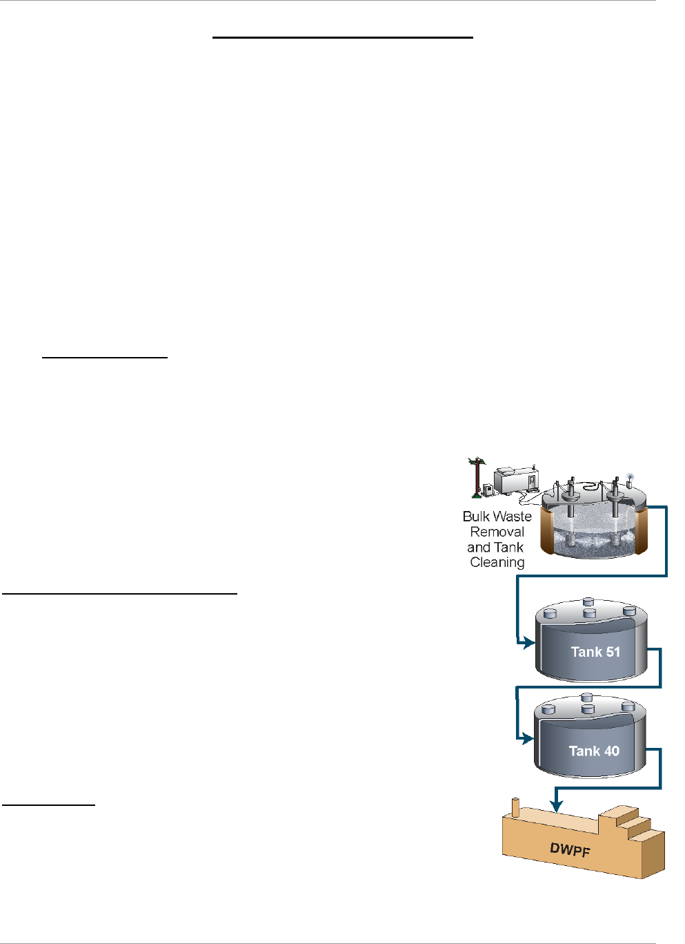
The basic steps for sludge processing (Figure 4-1) are:
1. Sludge removal from tanks
2. Low-Temperature Aluminum Dissolution (LTAD), if needed (in Tank
51)
3. Blending and washing of sludge (in Tank 51)
4. Sludge feeding to the DWPF (from Tank 40)
5. Vitrification in DWPF.
Low Temperature Aluminum Dissolution
High-heat sludge generated from the Canyon H-Modified (HM) process has high
amounts of aluminum solids as gibbsite or boehmite. Some of this aluminum can
be removed from the sludge by dissolution of the aluminum and subsequent
removal by decanting of the liquid phase. This reduces the number of canisters
needed to disposition the sludge, due to the lowered sludge solids mass and
improved waste loading in the glass. Dissolution is achieved by application of
added caustic, elevated temperature, mixing, and sufficient reaction time. “Low
Temperature” refers to the use of a maximum temperature of around 75ºC to
achieve the dissolution, as demonstrated for SB5, SB6, and SB10. The dissolved
aluminum is processed with the salt waste. Sludge generated by the PUREX
process does not require LTAD.
Sludge Washing
Sodium and other soluble salts (e.g., sulfates, nitrates, nitrites) in DWPF feed are
reduced through sludge washing. Sludge washing is performed by adding water
to the sludge batch, mixing with slurry pumps, securing the pumps to allow
gravity settling of washed solids, and decanting the sodium-rich supernate to an
evaporator system for concentration. This cycle is repeated until the desired
molarity (typically 1.0 M Na) is reached. Some types of sludge settle slowly,
extending wash cycles. Sludge settling and washing typically constitutes ~75% of batch preparation time. The total
Figure 4-1—Sludge Feed Preparation

SRR-LWP-2009-00001 Liquid Waste System Plan
January 2019 Revision 21
Planning Summary and Results Page 12
number of washes performed, and volume of wash water used are minimized to conserve waste tank space. Sludge
batch size and wash volumes are also limited by the hydrogen generation rate associated with radiolysis of water. Tank
contents are mixed on a periodic frequency to release hydrogen retained within the sludge layer, resulting in a limited
window within operating constraints for gravity settling. Once sludge washing has achieved its chemical composition
objective and the batch has been qualified for compliance with the DWPF Waste Acceptance Criteria (WAC), it is
transferred to Tank 40 for feeding into DWPF in small (5 kgal– 10 kgal) batches.
4.2 DWPF Operations
Washed sludge is transferred to the DWPF facility where it is combined with the high-level waste streams from salt
processing (discussed below) for vitrification into glass canisters and stored on-site pending disposition.
Historically, melter performance has been the limiting factor for DWPF throughput. The DWPF melter had produced
an average of 215 canisters/yr before melter bubblers were installed. When bubblers were installed in September 2010,
however, the melter capacity improved such that, in FY12 a record 277 canisters were poured and a monthly record of
40 canisters were poured in August 2013. The feed preparation systems internal to DWPF have demonstrated a capacity
of greater than 325 canisters/yr, e.g., the 337 canisters poured from July 2011 thru June 2012. In this Plan, the canister
production rate is matched to ARP/MCU or SWPF production rate. The early years of the plan require fewer canisters
to support the ARP/MCU or SWPF production of SE. DWPF, however, has a demonstrated capability of producing the
maximum annual rate forecast in this Plan of 300 canisters/yr.
The declaration of the HGR PISA in February 2017 is currently limiting DWPF operations (see section 5.6 Additional
Technical Assumptions, the Nuclear Safety subsection). Resolution of the limitation is expected upon full
implementation of the glycolic flowsheet.
Total Canister Count
Total canister count is primarily based on the mass of sludge in a tank that must be emptied, the ability to perform
aluminum dissolution, and the need to add sludge modifiers to meet physical and chemical requirements for DWPF
processing. Providing tank space for SWPF and ongoing waste removal may require transfer of sludge to a temporary
storage location (sludge hub tank). Limits on the mass of sludge that can be physically managed in a sludge batch may
dictate an increase or decrease in both solids loading and canister generation rate. There is also a minimum practical
operating rate (approximately five canisters per month) for keeping the DWPF processes functioning. Additionally, a
minimum canister production rate is required to support salt processing, based on the amount of SE and monosodium
titanate (MST) generated. SWPF processing of 9 Mgal/yr with NGS is anticipated to require over 275 canisters per
year.
Two-step Production Improvement Approach
To support higher glass throughput, the DWPF melter was retrofitted with four bubbler systems and the melter off-gas
system was optimized in September 2010. The second step of DWPF production capacity improvement program
addresses streamlining the DWPF feed preparation system. Several process improvements are planned to streamline
the DWPF feed preparation system which are required to support SWPF operations at a feed rate greater than 6 Mgal
per year:
● Implementation of an alternate reductant, i.e., the glycolic flowsheet
● Processing of cesium SE in the slurry mix evaporator (SME).
Reduction of liquid addition in DWPF supports receipt of SE from SWPF. Beneficial reuse of DWPF recycle for waste
removal and tank cleaning, in lieu of water additions, supplements recycle reduction and supports maintenance of Tank
Farm capacity (see §4.6 below).
Future estimated canister production, by year is shown in Appendix H—Canister Storage. The canister rates include
two one-week outages every year to allow for routine planned maintenance and another two weeks for the site-wide
steam outage each year.
Failed Equipment Storage Vaults and Melter Storage Boxes
The major component of the DWPF process is the Melter which has a finite operational life. While the original design
of the DWPF facility forecast a melter replacement every two years, the first melter operated over eight and a half years
before it reached its end of life. Melter 2 had operated fourteen years when it reached the end of life in 2017. This Plan
assumes one additional melter change will be required in 2029, at which time Melter 3 will have been in service for
twelve years.
Liquid Waste System Plan SRR-LWP-2009-00001
Revision 21 January 2019
Page 13 Planning Summary and Results
Disposition of highly radioactive failed melters requires specially designed transport and storage Melter Storage Boxes
(MSB) which are placed in underground Failed Equipment Storage Vaults (FESVs) for interim storage. The original
DWPF design has two FESVs contained within one construction unit. Each FESV is designed to store one MSB
containing a failed melter.
Melter 1 was placed in FESV 2 in December 2002. Melter 1 (inside MSB 1) had a relatively low external radiation
field. It was placed in the northernmost vault since the next vault pair to be constructed would be adjacent to FESV 2.
Melter 2 was placed in FESV 1 in May 2017. Space has been reserved for construction of up to ten FESVs, if needed.
This Plan assumes FESV 3 and 4 preparation begins in 2020 and requires two years for completion. Construction of
MSB 3 is forecast to be completed in FY21. MSB 3 will not be required until Melter 3 is nearing end of life.
Currently, the FESV 200-ton gantry crane is designed to interface only with an MSB designed primarily to contain
failed melters. The placement of other large failed DWPF equipment (which do not have disposal paths) in FESVs has
been considered but the complete engineered system to move large contaminated equipment from the 221-S Canyon to
the FESV has not been designed or constructed. Alternative methods for disposal of large contaminated equipment
from DWPF (not including melters) are being evaluated.
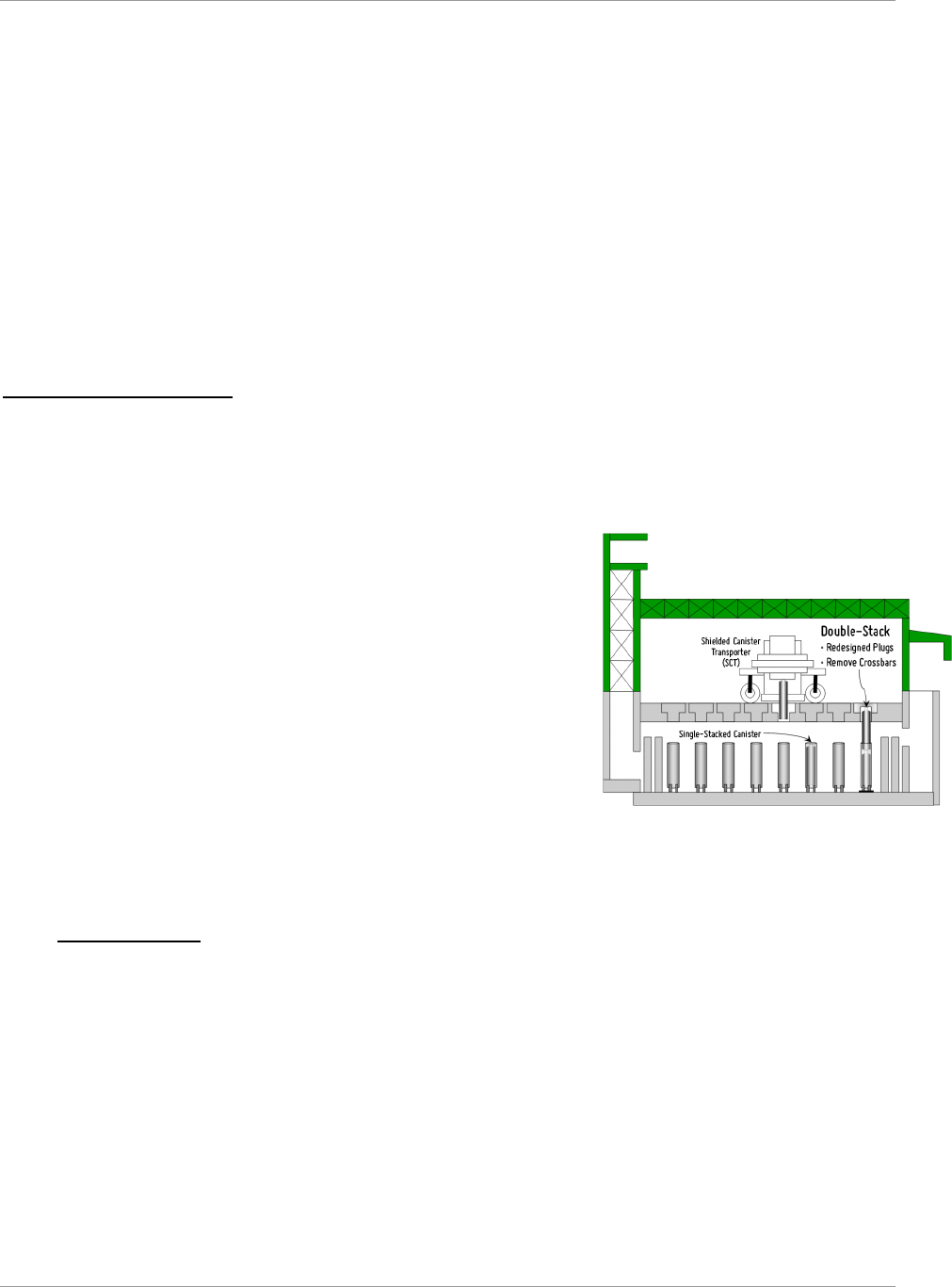
Glass Waste Canister Storage
The canisters of vitrified HLW glass produced by DWPF are currently stored on-site in dedicated interim GWSBs. A
Shielded Canister Transporter moves one canister at a time from the Vitrification Building to a GWSB. The schedule
for filling the GWSBs is found in Appendix H—Canister Storage. The schedule assumes that starting in FY20 all
current production canisters are double stacked in GWSB 1 (Figure 4-2—Double Stacking) within the guidelines of
Heat Transfer Analysis of Double Stacking of Canisters in the Glass Waste Storage Building #1
16
.
GWSB 1 consists of a below-grade seismically qualified concrete vault
containing support frames for vertical storage of 2,262 standard canisters. In
FY15, GWSB 1 began conversion for stacking two canisters in each storage
location for a total capacity of 4,524 standard canisters. As of January 1, 2019,
GWSB 1 contained 1,912 radioactive canisters and two archived non-
radioactive canisters.
GWSB 2, with a similar design to GWSB 1, has 2,340 standard storage
locations. The first radioactive canister was placed in GWSB 2 on July 10,
2006. One archived non-radioactive canister is in GWSB 2. As of January 1,
2019, GWSB 2 stored 2,251 radioactive canisters. See Appendix G—GWSB
Utilization for current utilization of the GWSBs
Additional glass waste storage capacity will be required, with availability
beginning in FY30 as current storage capacity is 6,861 and the total projected
storage requirement is 8,121 for a shortfall of 1,260 canisters. The schedule
for shipment of the canisters from SRS is not included in this Plan. It will be developed upon availability of a permanent
federal repository.
4.3 Salt Processing
As highlighted in the Introduction, this Plan includes the use of a series of salt treatment processes over the life of the
program, including ARP/MCU, TCCR, and SWPF. Appendix A—Salt Solution Processing reflects the breakdown of
the volumes treated from each of the processes by year. Using the input assumptions for this Plan, over 100 Mgal of
salt solution from the Tank Farms will have been processed over the life of the program; over 9.8 Mgal were processed
by December 2018. SWPF is planned to process most of this salt solution waste.
Salt preparation capability is limited by the number of blend tanks available to prepare salt batches. A single tank is
capable of preparing 4 Mgal/yr. In the first year of SWPF operations, Tank 21 (Type IV) and Tank 41(Type III) serve
as blend tanks. Thereafter, two Type III tanks, Tank 27 and Tank 42, will be equipped for blend tank service allowing
the Tank 21 to be converted for TCCR service. The three blend tanks will support the planned SWPF operating rate of
9 Mgal/yr after the initial year of operation. When FTF is ready for closure, Tank 24 (Type IV) will replace the FTF
blend tank, Tank 27, for the last two years of SWPF operations.
Figure 4-2—Double Stacking
SRR-LWP-2009-00001 Liquid Waste System Plan
January 2019 Revision 21
Planning Summary and Results Page 14
Other factors limiting salt processing capacity with the strategy to compensate for the limitation:
SE & MST processing in DWPF at the planned rates: Achieving greater than 7.2 Mgal/yr of SWPF
processing will require reducing the SE volume through implementation of NGS at SWPF in addition to other
facility enhancements
Decontaminated Salt Solution (DSS) processing in SPF at the planned rates: Enhanced Low Activity
Waste Disposal (ELAWD) Phase II, along with 24/7 operations are required to ensure SPF’s ability to process
the DSS stream from SWPF when SWPF operates at rates greater than 6 Mgal/yr.
Equipment Reliability Upgrades: Equipment upgrades such as Tank Farm East Hill Utilities and Saltstone
Mixer re-design will provide increased attainability rates
Salt Dissolution Efficiency: Increasing the salt dissolution efficiency enhances reliability of salt batch
preparation. Revise safety basis requirements to maximize the salt dissolution rate utilizing commercial
submersible mixing pumps (CSMPs)
Salt Batch Qualification: Part of the salt batch preparation time is for qualification analysis and
documentation. The salt batch qualification process can be streamlined through analyte reduction and the
automatic electronic Waste Acceptance Criteria (eWAC)
Transfer Line Integrity: Occasionally, transfers are delayed due to Out of Service (OOS) transfer lines from
failed pressure tests. Devise improved transfer line integrity assurance
Offsite Dry Feed Preparation: Dry feed preparation at SPF requires the use of the existing silos to mix the
components of the dry feed. An offsite dry feeds mixing plant would allow pre-mixing the dry feeds before
reaching the Saltstone facility to increase dry feeds capacity and enable use of all four silos
Pre-Transfer Flammability Calculations: Currently engineering calculations are required prior to transfer
to ensure the integrity of the flammability control program. Revision of the Tank Farm flammability program
could minimize Engineering calculations and evaluations prior to performing transfers
Frit Development: Current frit recipes are not adequate to support the higher SWPF throughput projected in
this Plan. Develop new Frit recipes to handle the increased amount of MST sent to DWPF from SWPF
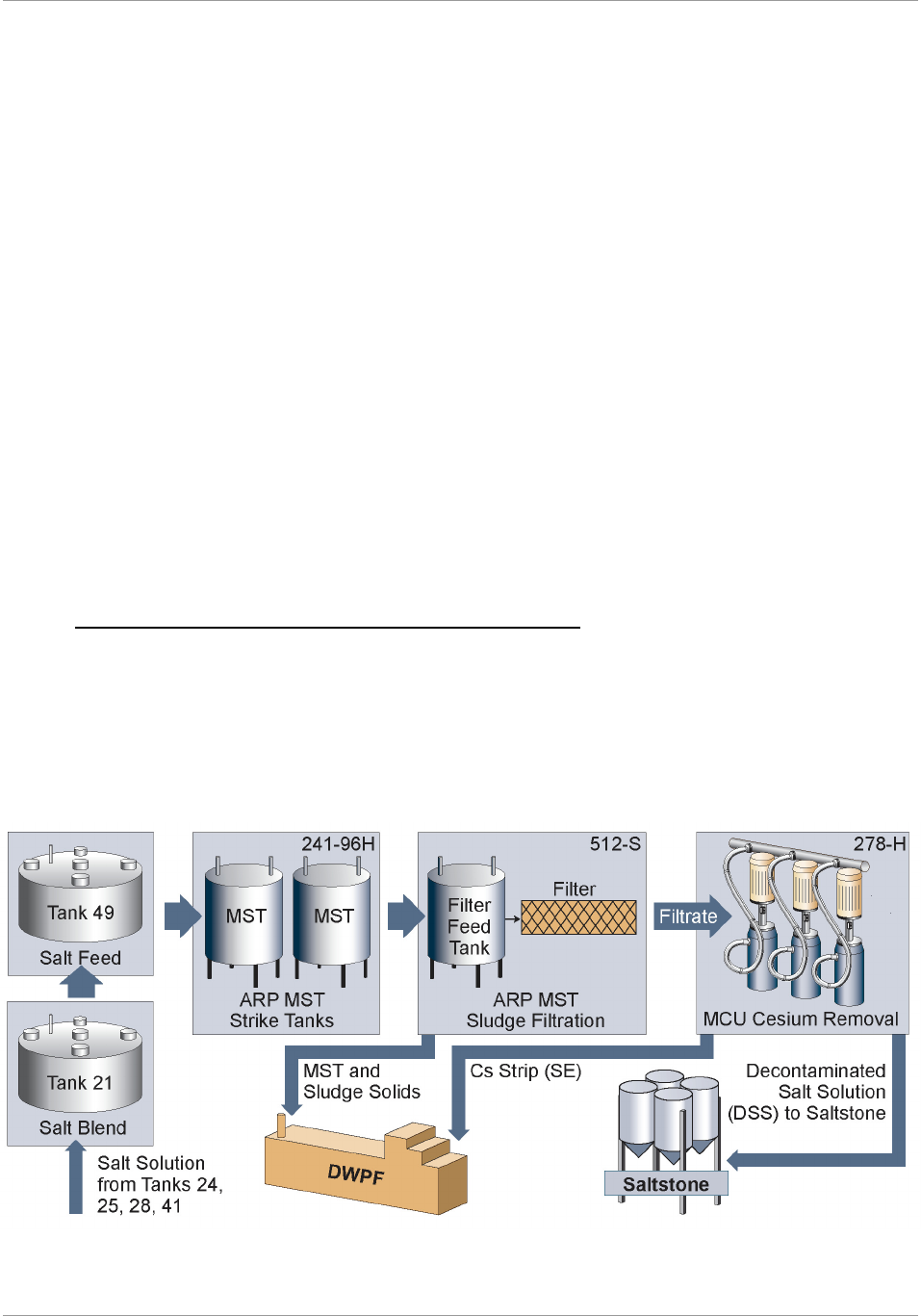
4.3.1 Actinide Removal Process / Modular CSSX Unit (ARP/MCU)
Salt waste is currently processed through ARP/MCU. A summary of the process is shown in Figure 4-3—Schematic of
the ARP/MCU Process.
The ARP decontaminates salt solution via adsorption of strontium-90 (Sr-90), actinide, and entrained sludge solids in
the salt solution onto MST followed by filtration or settling. The actinides, Sr-90, and MST-laden sludge waste stream
are transferred to DWPF for vitrification and the remaining clarified salt solution is transferred to the MCU process. In
2016, a demonstration of ARP was initiated to demonstrate that, with the correct salt batch makeup, MST addition is
not necessary to meet the SPF WAC for the ARP/MCU batches.
Figure 4-3—Schematic of the ARP/MCU Process
Liquid Waste System Plan SRR-LWP-2009-00001
Revision 21 January 2019
Page 15 Planning Summary and Results
The MCU process extracts Cs from the clarified salt solution using CSSX chemistry. The DSS is subsequently
transferred to Tank 50 for feed to the SPF, and the SE solution from the CSSX process is transferred to the DWPF for
vitrification.
The ARP/MCU process was constructed and initially permitted for a three-year service period, bridging the crucial
period before the startup of the SWPF. With the delay of SWPF, however, ARP/MCU has been enhanced and improved
to provide a longer-term option for salt disposition. The original goals of the ARP/MCU process were first treat salt
solution prior to the start of SWPF; and second provide operational experience and lessons learned for the SWPF
project.
Actions taken since startup of ARP/MCU have demonstrated an increased processing rate from the original design of
1 million gallons per year to approximately 1.4 million gallons per year. Enhancements and improvements include
chemistry adjustments at Tank 49, reduced cycle-times, and redesign and replacement of the secondary filter at 512-S.
Efforts continue to improve equipment reliability, reducing unexpected downtime to improve overall attainment.
Improved Decontamination
In the fourth quarter of FY13, the original solvent formula was replaced with NGS. Operation of ARP/MCU with NGS
results in more efficient removal of cesium from the treated salt solution than the original solvent formula. This
increased cesium removal efficiency (decontamination factor or DF) allows ARP/MCU to produce a DSS stream with
a residual cesium concentration much less than previously achieved. The improved DF will enable continued operation
of ARP/MCU while minimizing the curies disposed in the SDF. ARP/MCU will continue to be operated at a nominal
6 gpm until the facility is shut down for final SWPF tie-ins.
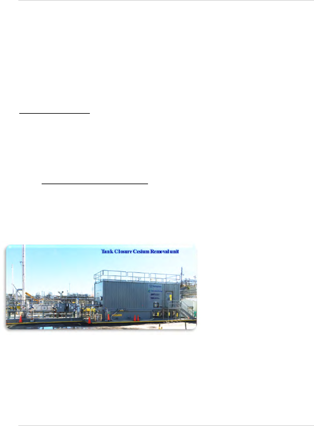
4.3.2 Tank Closure Cesium Removal (TCCR)
The TCCR initiative consists of an ion exchange process for the removal of cesium from liquid salt waste to provide a
supplemental treatment capability and improved confidence in supporting the desired acceleration of waste retrieval
and tank operational closure efforts. Building on the experience of modular commercial nuclear plant decontamination
and following the disaster response associated with Fukushima, the technology exists in industry to accomplish larger
scale, selective removal of the cesium component of the bulk salt waste effectively and efficiently. A commercial
supplier designed, fabricated, tested, and delivered a modular cesium removal system which has been deployed at Tank
10 for the treatment of liquid salt waste.
This Plan assumes successful demonstration
of the initial TCCR unit (TCCR-1) in HTF to
treat dissolved salt waste from Tank 10. The
configuration consists of temporary process
structures located near Tank 10 and Tank 11,
so the cesium removal process takes place
outside of the tank. The DSS is temporarily
stored in Tank 11 before transfer to Tank 50
and then to SPF for disposal. After Tank 10
is complete, the TCCR-1will process Tank 9
salt. After two years of processing Tank 9
materials, the TCCR-1 is planned for
relocation to Tank 21 to continue processing
while Tanks 9, 10, and 11 are closed. Tank 23 is planned to hold the DSS from the Tank 21 TCCR operation for periodic
transfer to Tank 50 and ultimate disposition in Saltstone.
A second TCCR unit (TCCR-2) is planned for FTF to treat dissolved waste from F-Area tanks. Tank 4 and Tank 7 are
used to support salt dissolution and feed batch preparation. The temporary process structures would be located near
Tank 4 with the cesium removal process taking place outside the tank. After four years of operations, when TCCR-2
has completed processing the suitable salt in FTF allowing the closure of the old-style tanks, it will be relocated to
Tank 21 as well.
Once the ion exchange media in a column becomes loaded with cesium to the extent practical (“spent”), the column
(with media) will be removed from the system and replaced with a new ion exchange column loaded with fresh media.
The spent column will be transported to an ISS location within the tank farm. While the spent resin is designed to be
able to be dispositioned via DWPF, the ISS concept reduces initial process facilities and costs while also allowing for

SRR-LWP-2009-00001 Liquid Waste System Plan
January 2019 Revision 21
Planning Summary and Results Page 16
identification and evaluation of potential future disposal alternatives. For planning purposes, this Plan assumes an
alternate disposal option is approved by regulatory authorities and implemented. The current projection is that over 120
TCCR columns will be moved to ISS prior to final disposition (Appendix I—TCCR Columns Interim Safe Storage)
The water used to support heel removal and prepare sludge batches at the end of the program will be treated with a
TCCR unit relocated to be near Tank 51; the decontaminated wash water will be sent to Tank 50 and then Saltstone for
treatment and disposition. This plan assumes any required changes to the Saltstone WAC or regulatory permits will be
made.
4.3.3 Salt Waste Processing Facility (SWPF)
The SWPF processing rate is based on an assumed 100% availability for the Tank Farm feed as well as DWPF and SPF
receipt of the SWPF discharge streams. The SWPF treatment process is planned to produce DSS that meets the SPF
WAC limit.
Currently, factors limiting SWPF production to 6 Mgal/yr include:
Transfer lines and equipment for transferring feed from the Tank Farms to SWPF and the effluents from SWPF
to Tank 50 (the SPF feed tank) and DWPF
Provision of blend tanks to provide feed to support feeding SWPF at the rated capacity
Total cycle time in SWPF
SE & MST processing in DWPF at the planned rates. Achieving greater than 7.2 Mgal/yr of SWPF processing
will require reducing the SE volume by increasing the concentration factor to 20 or greater
DSS processing in SPF at the planned rates. ELAWD Phase II, along with 24/7 operations, are required to
ensure SPF’s ability to process more than 6 Mgal/yr of DSS from SWPF.
To mitigate these limitations, modifications to the facilities are planned, including:
Infrastructure: Completion of Salt Disposition Initiative (SDI) activities for physical tie-in to SWPF
Tank Farms: Salt dissolution, blending, batching, and qualification at a pace sufficient to provide feed at
design rates and enable additional tanks to enter blend tank service
DWPF: Improvements described in Section 4.2 (above) enhance the ability to process SE to support an SWPF
feed rate greater than 6 Mgal/yr
SPF: ELAWD II improvements described in Section 4.4 (below) enhance SPF’s ability to process the DSS
stream from SWPF to support an SWPF feed rate greater than 6 Mgal/yr.
Additionally, storage for the resultant waste streams must be provided, including:
Construction of future SDUs to support disposition of saltstone from SWPF DSS stream processing at design
rates
Construction of future glass waste storage capability to support canister storage for SWPF SE & MST stream
processing at design rates
Blend Tank Selection
“Source” and “Hub” tanks supply and collect the source material to be used in compiling the salt batch. “Blend” tanks
receive and mix the source material to create the salt batch. The “Feed” tank receives the batch from the Blend tank
and feed it to ARP/MCU or SWPF, when it becomes operational. To support SWPF’s maximum throughput of 9 million
gallons per year, three blend tanks are planned to be operated simultaneously.
There are three basic requirements for a tank to be eligible for use as a blend tank. The tank must be able to:
Accept material from other tanks (receiving capabilities).
Blend the material from the Source tanks (mixing capabilities)
Send 1 million gallons of prepared feed to the Feed tank (transfer capabilities to Tank 49).
Additionally, the salt dissolution campaigns are planned according to the following priorities:
1. Continual safe storage of liquid waste in tanks and vitrified canisters in storage.
2. Complete LW System operational closure by the end of FY33.
3. Complete operational closure of F Tank Farm by end of FY28.
4. Process liquid salt waste (e.g., dissolved salt solution, supernate) in FY16 through FY22 in accordance with
the South Carolina Department of Health and Environmental Control (SCDHEC) “Agreement” (including
consideration for Force Majeure conditions).
5. Remove the bulk of the waste in the old-style H-Tank Farm tanks in the water table (i.e., Tanks 9, 10, 13, 14)
by end of FY23.

Liquid Waste System Plan SRR-LWP-2009-00001
Revision 21 January 2019
Page 17 Planning Summary and Results
6. Complete operational closure of the 1F Evaporator by the end of FY23.
It should be noted that the remaining Type IV tanks in H-Tank Farm are integral in closing F-Tank Farm as it provides
much needed usable tank space. Therefore, the priority to close Type IV tanks is low despite them also being old-style
tanks.
Tank 49 is the current Feed tank for ARP/MCU and will remain as the Feed tank for SWPF. This Plan requires Tanks
41, 42, and 27 to become blend tanks once SWPF is operational. As infrastructure improvements occur and demands
change, however, the selection of blend tanks will change accordingly to operate as safely and efficiently as possible.
Tank 41 (Type IIIA) is currently undergoing salt dissolution, which once completed, will leave the tank ready for
conversion to blend tank service. The residual solids are not expected to interfere with batch compilation. Flammability
and corrosion controls regarding these solids will be managed. A mixing pump will be installed making Tank 41 the
second blend tank.
Current efforts in modifying piping within the 2H evaporator cell to reduce transfer conflicts would result in Tanks 41
and 42 having direct transfer paths to Tank 49. This also makes Tank 42 (Type IIIA) a reasonable blend tank candidate.
The concentrated supernate currently within Tank 42 is planned to be both transferred and used in SWPF batches.
Additionally, the old mixing pumps within Tank 42 will be tested and if needed, replaced to ensure mixing capabilities.
Tank 27 (Type IIIA) was identified as a future Blend tank as it is in F-Area Tank Farm which provides multiple transfer
paths to the other F-Area Tank Farm tanks. This reduces the number of inter-area transfers required to remove salt from
F-Area Tank Farm. The tank is currently planned to go through salt dissolution, which would, once completed, provide
adequate tank space for batch compilation. Like Tank 41, the residual solids are not expected to interfere with batch
compilation and controls are manageable. Mixing device(s) will also need to be installed.
4.4 Saltstone Operations
The Saltstone operation consists of two main components. The SPF contains the tanks and equipment necessary to
receive the feed and treat and process it into saltstone grout. The grout is pumped from SPF into the SDF, consisting
of several SDUs for final disposition.
Saltstone Production Facility
SPF receives and treats the salt solution to produce grout by mixing the liquid feed stream with cementitious materials
(cement, flyash, and slag). A slurry of the components is pumped into the SDUs, located in SDF, where the saltstone
grout solidifies into a monolithic, non-hazardous, solid LLW form.
To enable SPF to accommodate the increases in feed volume from SWPF, the SPF dry feed preparation system must
be streamlined. This will be accomplished in the second phase of ELAWD. Additionally, to support SWPF processing
rates above 6 Mgal/yr, SPF operations will be conducted on a 24/7 schedule requiring increased staffing over the current
4/10 schedule. ELAWD Phase II and the staffing increase are forecast to be available after the first year of SWPF
operations.
ELAWD Phase II (SPF Dry Feed Mods)
Several operations and equipment reliability improvements are required to enhance the operation of SPF feeding SDF:
Silo bin discharge—Rework existing silo bin discharge system to allow silos to operate at full capacity.
Implement software changes that will allow air to be pulsed through the silo during downtimes to prevent
packing and bridging
Knife gate valve or equivalent—Install knife gate valve assembly at each silo to enhance the system’s
abilities to handle inconsistencies with bulk materials and aid in dry material recipe accuracy
Screw feeder—Replace the existing obsolete screw feeder
Weather protection—Enclose the Premix Feed Bin and Loss-In-Weight hopper to protect the many flexible
couplings and joints that are susceptible to water intrusion
Flexible couplings—Upgrade each flexible coupling to provide improved sealing and weather resistance
Dust collectors—Update Silo 2 dust collector to improve simultaneous truck unloading capacity for Silos 1,
2, and 3.
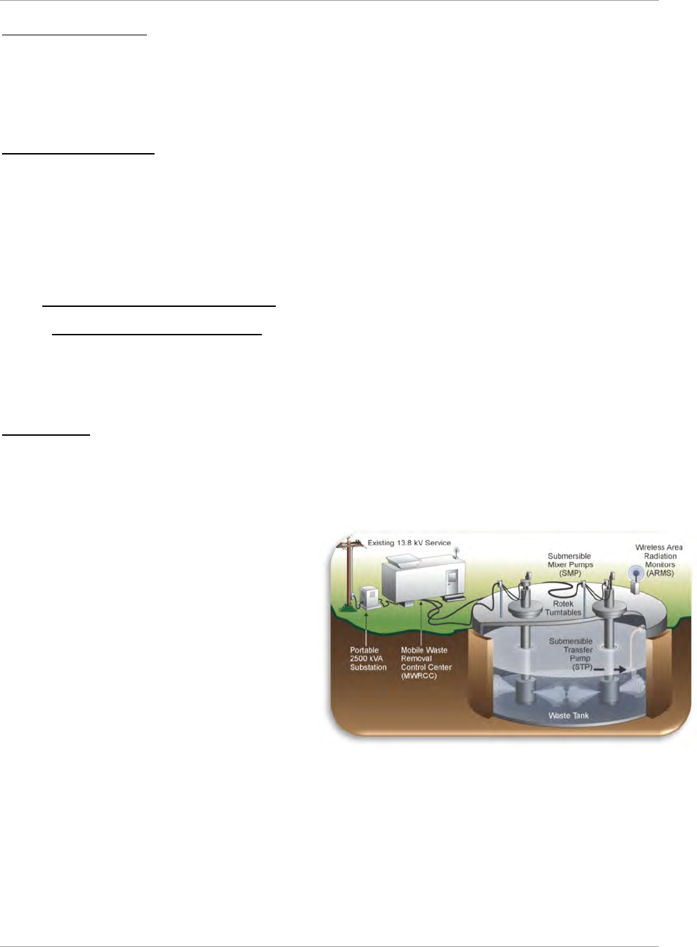
SRR-LWP-2009-00001 Liquid Waste System Plan
January 2019 Revision 21
Planning Summary and Results Page 18
Saltstone 24/7 Operations
Operations and equipment reliability improvements are required to enable 24/7 operation of SPF feeding SDF:
Lightning protection upgrades – Install lightning protection throughout the Saltstone facility to minimize
process equipment damage during inclement weather and to maximize critical process equipment availability
Process air compressor replacement – Replace outdated process air compressors to support dry feed system
operations and serves as a backup supply to the 210-Z instrument air system.
Saltstone Disposal Facility
SDU-2 and SDU-5 (both of which are full) and SDU-3 each consist of two cells nominally 150 feet diameter by 22 feet
high. After accounting for interior obstructions (support columns, drainwater collection systems, etc.), the nominal
useable volume of a cell is approximately 2.8 Mgal. Nominally, 1.76 gallons of grout is produced for each gallon of
DSS feed, yielding a nominal cell capacity of approximately 1.5 Mgal of feed. SDU-6, which is currently the active
SDU, consists of a single cell 375 feet in diameter by 43 feet high. SDU-6 has the capacity to disposition over 32 Mgal
of saltstone containing approximately 18.7 Mgal of feed. Future SDUs will have the same capacity as SDU-6. The last
SDU will be sized as needed to complete the LW mission.
4.5 Waste Removal and Tank Closure
4.5.1 Waste Removal and Tank Cleaning
The first step in the disposition of sludge and salt waste is bulk waste removal. Sludge is removed from the waste tank
and sent to a hub tank, a tank set up to receive and transfer sludge to the feed preparation tank, or directly to the feed
preparation tank ensuring sludge waste is continuously available for treatment at DWPF. Salt is dissolved, removed,
and staged for treatment at ARP/MCU or SWPF.
Waste Removal
If permanent infrastructure is available, sludge removal planning maximizes the use of this infrastructure to most
effectively remove waste. This planning includes the use of structural steel, cable trays, existing mixer pumps, transfer
pumps, and ventilation. If permanent infrastructure is not available, then temporary equipment may be used on some
waste tanks to perform waste removal (see Figure 4-4). Portable and temporary equipment would then meet tank
infrastructure needs.
The primary components of a temporary system
include:
● Reusable mixing pumps
● Portable field operating station containing
pump drives and controls
● Portable substation to provide 480-, 240- and
120-volt power
● Disposable commercial transfer pumps.
The temporary equipment is deployed at the tank as a
field operating station, providing temporary power and
control for waste removal equipment. When waste
removal is completed on one tank, the equipment can
be reconfigured to support waste removal on the next
tank. Pumps are sized to fit through the existing 24-inch
riser openings in the waste tanks. To the extent that risers are
available, pumps are set in optimal configurations within the waste tanks. For submersible mixer pumps (SMP),
product-lubricated bearings and motor cooling eliminate the need for bearing and seal water supply. These pumps have
exterior fittings and fixtures, so the pumps can be decontaminated, minimizing radiation exposure to personnel during
relocation to another tank. CSMPs, however, have demonstrated preferable performance to SMPs and are currently
planned for sludge removal as well as salt removal. Disposable transfer pumps transfer the waste to a receipt or hub
tank using existing underground transfer lines and diversion boxes. If the transfer system is degraded or non-existent,
above-grade transfer lines may be deployed, rather than investing in costly repairs. Temporary shielding is supplied as
necessary to minimize exposure to personnel.
Figure 4-4—Temporary Waste Removal
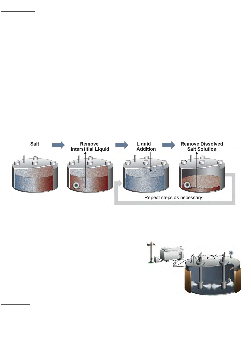
Liquid Waste System Plan SRR-LWP-2009-00001
Revision 21 January 2019
Page 19 Planning Summary and Results
Sludge Removal
Sludge removal operations are typically conducted with several mixing pumps. Sufficient liquid is added to the tank to
suspend sludge solids. Existing supernate is used, when practical, to minimize introduction of new liquids into the
system. Operation of the mixing pumps suspends the solids, which are then transferred as a slurry from the tank. This
operation is repeated, periodically lowering the mixer pumps, until the remaining contents of the tank can no longer be
effectively removed by this method.
Sludge batches were originally configured to preferentially remove sludge from Type I and II tanks. Most of the sludge
has been successfully removed from the old-style tanks. Tank 13, a Type II tank in HTF is being used to store and
transfer sludge heels from other Type I and II tanks. Final Tank 13 heel removal is planned for 2025. Tanks 33, 34, 35,
and 39, Type III tanks, are planned for use as sludge hub tanks, as needed.
Salt Removal
Salt waste removal strategy is developed on a tank-specific basis and may employ a variety of approaches. Some general
approaches are briefly discussed here.
Tanks that are full of salt and at the beginning of the salt waste removal process may be approached using a Drain,
Add, Remove (DAR) method (see Figure 4-5—Drain, Add, Remove Method for Salt Waste Removal). The dissolution
liquid may be added in small batches or may be added at a very slow rate while simultaneously removing dissolved
salt solution. The Add step is the most effective if the dissolution media can be sprayed onto the salt surface. Care must
be taken to minimize the formation of preferential flow channels during the dissolved salt solution removal. The process
ends with the removal of the dissolved salt solution.
Salt waste dissolution using Drain, Add, Remove eventually becomes
inefficient. At this point the approach changes to Mechanical
Agitation which will likely be active mixing using long shaft pumps.
The dissolution liquid (e.g., inhibited water [IW], well water [WW],
DWPF recycle) is added and then the mixing pumps are used to create
contact between the salt and the dissolution liquid. The dissolved salt
solution is removed from the tank in several batches. This approach is
best suited to tank configurations with a large vapor space relative to
the volume of salt remaining (see Figure 4-6—Mechanical Agitation
Salt Removal)
Heel Removal
After completion of waste removal using the technologies discussed
above, heel removal is performed. Heel Removal can consist of a
combination of mechanical heel removal and chemical cleaning. In general, mechanical heel removal is done prior to
chemical cleaning, and is discussed below in some detail. Depending on tank conditions, however, chemical cleaning
may be performed prior to mechanical heel removal or some mechanical heel removal and some chemical heel removal
Figure 4-5—Drain, Add, Remove Method for Salt Waste Removal
Figure 4-6—Mechanical Agitation Salt Removal

SRR-LWP-2009-00001 Liquid Waste System Plan
January 2019 Revision 21
Planning Summary and Results Page 20
may be performed iteratively to provide removal to the extent technically practicable from an engineering perspective
and the highly radioactive radionuclides removed to the maximum extent practical.
Mechanical Heel Removal
For mechanical heel removal, this Plan assumes vigorous mixing continues, using mixing pumps, until reaching a point
of diminishing returns. Additional mechanical removal may be achieved through directing pump discharges in specific
patterns to impact remaining material.
Chemical Cleaning
Chemical cleaning may be performed on sludge tanks when mechanical heel removal has not removed the material to
the extent technically practicable from an engineering perspective and the highly radioactive radionuclides removed to
the maximum extent practical. In bulk oxalic acid (OA) cleaning, the tank is modified to address chemical compatibility
concerns and OA is added to the tank and mixing pumps operated. The contents of the tank are agitated for a short
period and then transferred to a receipt tank for neutralization. In caustic cleaning, a sludge heel is subjected to LTAD
conditions (see § 4.1) to dissolve a significant amount of aluminum solids. This process is repeated one to three times
based on chemical flowsheet projections.
Tanks with Documented Leak Sites
Several Type I, II, and IV tanks have documented leak sites. All Type IV tanks having documented leak sites have been
operationally closed; however, waste removal operations on some of the Type I and II tanks could potentially reactivate
old leak sites or expose new leak sites in those tanks. Contingency equipment and procedures will be utilized to contain
leakage and prevent release to the environment. Specific plans will avoid liquid levels above known leak sites, when
feasible, and focused monitoring will be employed where these levels cannot be avoided. Because of program progress
to date, of the 14 SRS tanks (all old-style tanks) with leakage history:
● 6 are operationally closed and grouted (Tanks 5, 6, 12, 16, 19, and 20)
● 2 are supporting the TCCR process (Tanks 10 and 11)
● 1 is awaiting heel removal activities to commence (Tank 15)
● 3 contain essentially dry waste, with little or no free liquid supernate (Tanks 1, 9, and 14)
● 2 contain liquid supernate at a level below known leak sites (Tanks 4 and 13).
Annulus Cleaning
Some Type I and II tanks have waste in the annular spaces, typically a soluble form of salt appearing as dried nodules
on tank walls at leak sites and at the bottom of the annulus pan. These tanks will be inspected to determine if Annulus
Cleaning is required. For those tanks requiring annulus cleaning, this waste will be removed from the annulus to the
extent technically practicable from an engineering perspective and the highly radioactive radionuclides removed to the
maximum extent practical before declaring the tank ready for grouting.
4.5.2 Tank Operational Closure and Stabilization
Type I, II, and IV tanks are planned for operational closure in accordance with a formal agreement between the DOE,
Region IV of the EPA, and SCDHEC as expressed in the SRS currently approved FFA. Eight of these tanks were
operationally closed and stabilized (grouted): FTF Tanks 17 and 20 in 1997, Tanks 18 and 19 in 2012, Tanks 5 and 6
in 2013, and HTF Tank 16 in 2015 and Tank 12 in 2016.
Operational closure and stabilization consist of those actions following waste removal that bring liquid radioactive
waste tanks and associated facilities to a state of readiness for final closure of the Tank Farms complex, including:
Sampling and Characterization
Developing tank-specific regulatory documents
Isolating the tank from all operating systems in the surrounding Tank Farm (e.g., electrical, instruments, steam,
air, water, waste transfer lines, and tank ventilation systems)
Stabilizing by grouting of the primary tank, remaining equipment, annulus, and cooling coils
Capping of select tank risers.
This Plan assumes thirty-six months from the last removal of any material until completion of grouting.
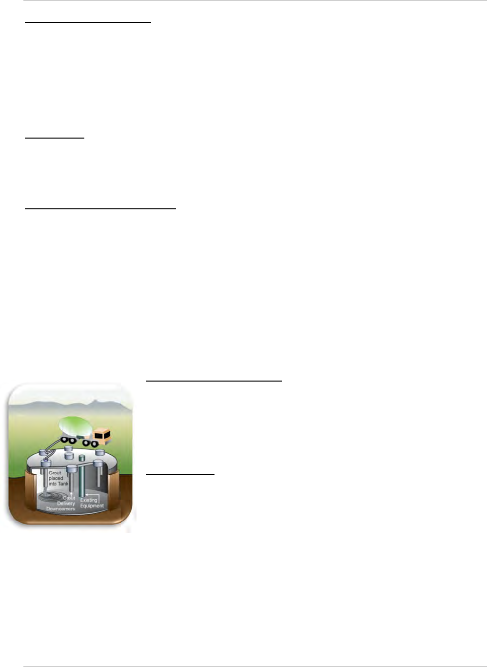
Liquid Waste System Plan SRR-LWP-2009-00001
Revision 21 January 2019
Page 21 Planning Summary and Results
Sampling and Characterization
Before declaring a tank ready for grouting, the tank and annulus are inspected, the residual volume is estimated, and
the residual is sampled in accordance with a sample plan. Laboratory analysis of the samples yields concentrations of
radiological and non-radiological constituents in the remaining material. The SCDHEC-approved Sampling Analysis
Program Plan and associated Quality Assurance Program Plan currently recognizes the Savannah River National
Laboratory (SRNL) as the laboratory that performs residual characterization analysis. Concentration and volume data
are used to characterize the residual material to produce radiological and non-radiological inventories for the Closure
Module (CM). Tank-specific closure documents and other regulatory documentation are prepared to demonstrate
compliance with State and DOE regulatory requirements as well as NDAA §3116.
Tank Isolation
Tank isolation is the physical process of isolating transfer lines and services from the tank. Isolating the tank from tank
farm systems and services prohibits chemical additions or waste transfers into or out of the tank. Further isolation of a
tank, after filling with grout, is planned to include cutting and capping or blanking mechanical system components (air
piping/tubing, steam piping, etc.) and disconnecting electrical power to process components on the tank.
Closure Documentation Development
An area-specific WD approach ensures the NDAA §3116 tank operational closure process is implemented as efficiently
as possible. PA and NDAA §3116 Basis Documents have been generated for each Tank Farm—one for FTF and one
for HTF. The NDAA §3116 Basis Documents include the waste tanks as well as ancillary structures located within the
boundary of the respective Tank Farm. The GCP was developed and approved by SCDHEC.
DOE Radioactive Waste Management Manual 435.1-1 mandates a Tier 1 Closure Plan and associated Tier 2 Closure
Plans. The Tier 1 plans are area-specific and provide the bases and process for moving forward with tank grouting.
This document is approved at the DOE-Headquarters level. The Tier 2 documents are tank-specific, follow the approved
criteria established in the Tier 1 documents, and are locally approved by DOE-SR.
Development of a tank-specific CM, per the State-approved GCP, follows completion of tank cleaning activities. The
CM describes the waste removal and cleaning activities performed and documents the proposed end state. Final
characterization data supports the performance of a Special Analysis which determines if final residual inventories
continue to support the conclusions of the area-wide PA.
Grout Selection and Manufacture
A reducing grout provides long-term chemical durability and minimizes leaching of
residual waste over time. The reducing grout selected is self-leveling, and encapsulates
the equipment remaining inside the tank and annulus. The grout also provides for
intruder prevention in tanks that do not have a thick concrete roof. Grouting activities
include field modifications, temporary ventilation installation, grout plant mobilization,
and grout procurement.
Grout Placement
Grout fill operations, including site preparation, pumper truck set up, grout plant set up
(if required), grout delivery lines, and grout equipment setup are established around the
tanks (see Figure 4-7). A sequence for tanks with an annulus will be developed so that
voids are filled and the structural integrity of the tank is maintained. Generally, grouting
the annulus and primary tank in alternating steps provides structural support for the tank
wall.
Figure 4-7—Grout Placemen
t
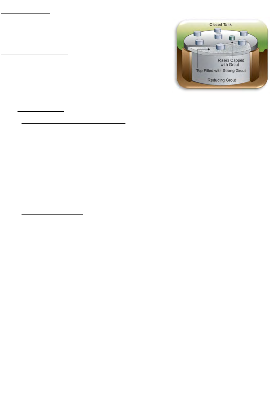
SRR-LWP-2009-00001 Liquid Waste System Plan
January 2019 Revision 21
Planning Summary and Results Page 22
Equipment Grouting
For tanks with installed equipment or cooling coils, internal voids are
filled with a flowable grout mixture. In those tanks where the cooling
coils have broken, alternative techniques are used to minimize voids in
the grout matrix.
Riser Grouting and Capping
The final step, after filling the tank, may include encapsulating select
risers. When necessary, forms are built around the risers and grout is
used to encapsulate the risers providing a final barrier to in-leakage and
intrusion. The final grouted tank configuration is an integral monolith
with minimal voids and ensuring long-lasting protection of human health
and the environment (see Figure 4-8).
4.6 Base Operations
4.6.1 Supporting Nuclear Material Stabilization
A continuing portion of the mission of the Tank Farms, especially HTF, is safe receipt, storage, and disposition of
waste yet to be received from H-Canyon and HB Line. This Plan supports nuclear material stabilization in H-Canyon
through 2030. Tank 39 will continue to receive H-Canyon waste through FY30. The 3H Evaporator system will
continue to operate without the need to replace the evaporator pot through FY26. This Plan assumes Tank 39 can
receive 200 kgal/yr from H-Canyon in FY19 through FY22. Beginning in FY22, HTF is forecast to receive up to 300
kgal/yr from H-Canyon through FY30.
An alternate disposal path for some waste (e.g., U, Pu, or Np bearing waste) allows insertion into a DWPF sludge batch
“just-in-time” via receipt into the sludge processing tank (Tank 51) or the DWPF feed tank (Tank 40). Plutonium
discards from H-Canyon through FY30 will be supported to the extent allowable without negatively impacting planned
canister waste loadings or failing to comply with canister fissile material concentration limits. Additionally, some of
the LLW from H-Canyon may be received into Tank 50 for direct disposal in SDF through FY30.
4.6.2 DWPF Recycle Handling
DWPF recycle is the largest influent stream received by the Tank Farm. In this Plan, disposition of the recycle stream
is handled through evaporation in the 2H Evaporator System and through the beneficial reuse of the low sodium
molarity (less than 1.0 molar sodium) recycle stream. The DWPF recycle rate will remain between 1.5 and 1.9 Mgal/yr
prior to SWPF operations. The rate depends on canister production rate and Steam Atomized Scrubbers (SAS) operation
as well as DWPF recycle reduction initiatives. The rate could increase to as high as 3.2 Mgal/yr after the startup of
SWPF because of extra water in the SE stream and MST slurry and because the higher Cs-137 concentrations could
require the operation of two SAS stages in the DWPF melter offgas system; currently, only one SAS stage is operated.
DWPF recycle is exclusively evaporated in the 2H Evaporator System due to chemical incompatibility with other waste
streams. It may, however, be beneficially reused for salt solution molarity adjustment, salt dissolution, heel removal,
etc. Beneficial reuse minimizes the utilization of the 2H Evaporator. DWPF recycle will be supplemented by inhibited
water (IW), as required, for salt dissolution and adjustment.
As an optimistic strategy, this Plan models the diversion of the DWPF recycle stream to ETP beginning in FY23. The
recycle stream will require pretreatment prior to transfer to ETP. A Systems Engineering Alternative Analysis will be
performed in FY19 to identify the type and method of pretreatment necessary to enable this diversion.
The decision to discontinue DWPF recycle to the Tank Farm provides several opportunities. The effect is to add two
tanks and an evaporator for general purpose use. This allows the 3H Evaporator to shut down in FY26 and undergo
waste removal without the need to restore evaporator operations. Sludge removed from the 3H feed tank (Tank 32) can
be sent directly to sludge batches as needed instead of being removed to other HTF tanks. This is a significant
simplification of the plan and avoids the cost of putting the 3H back in service following Tank 32 sludge removal.
Moving the evaporator support function from the HTF West Hill to the HTF East Hill allows the waste removal and
closure of the West Hill tanks (Tanks 29 thru 37, except 33 and 34 which are in FTF).
It is assumed that the 2H Evaporator will undergo a cleaning prior to being put in service as a general-purpose
evaporator. Tank 22 will be depleted of the silica rich solution sent from the DWPF. The spent wash water from Tank
Figure 4-8—Grouted Tank

Liquid Waste System Plan SRR-LWP-2009-00001
Revision 21 January 2019
Page 23 Planning Summary and Results
51 will be decanted to Tank 22 and either used for salt dissolution or sent for evaporation. Tank 22 contents will undergo
evaporator feed qualification before processing in the evaporator. Since the system will no longer be receiving silica
there should not be any concerns regarding sodium-aluminum-silicate formation within the evaporator vessel and there
should not be any solids formation related criticality concerns.
4.6.3 Transfer Line Infrastructure
Although efforts will continue to be made to keep transfers between tanks to a minimum, executing this Plan requires
more frequent transfers than have historically occurred in the Tank Farm, especially after the startup of SWPF, when
large volumes of salt solution will be delivered to SWPF. Because of the greatly increased pace of transfers after the
startup of SWPF, short downtimes due to unexpected conditions requiring repair will be more difficult to accommodate
without impact because the idle time of transfer lines will be reduced.
New infrastructure is required to accomplish transfers to support SWPF, while also continuing activities such as waste
removal and evaporation. Discoveries of unexpected conditions in existing transfer systems could impact the
installation of new transfer lines and equipment.
The transfers in this Plan are generally based on the known current infrastructure, modifications planned in the SWPF
transfer line tie-ins, and in projects for new facilities. The actions described can be executed as long as the planned
modifications are made, and significant failures of key transfer equipment do not occur or can be mitigated quickly
enough to allow activities to proceed as planned. This Plan, however, does not attempt to explain all the modifications
needed or anticipate the failure of specific pieces of transfer equipment.
4.6.4 Tank 48 Treatment
Tank 48 contains legacy organic from previous salt treatment processes. Several technologies have been considered,
including Fluidized Bed Steam Reforming and Copper Catalyzed Peroxide Oxidation, to treat the organic components
and enable the waste to be dispositioned as saltstone or vitrified glass. Systems Engineering Evaluations will select an
appropriate technology to allow Tank 48 treatment to begin in FY26 followed by operation closure.
4.6.5 Effluent Treatment Project
The ETP, located in H-Area, collects and treats process wastewater that may be contaminated with small quantities of
radionuclides and process chemicals. The primary sources of wastewater include the 2H and 3H Evaporator overheads
and H-Canyon contaminated water. The wastewater is processed through the treatment plant and pumped to Upper
Three Runs Creek for discharge at an NPDES permitted outfall. Tank 50 receives ETP residual waste for storage prior
to treatment at SPF and final disposal at SDF. A 35-kgal Waste Concentrate Hold Tank provides storage capacity at
ETP to minimize transfer impacts directly to Tank 50 or SPF during SWPF operations. Beginning in FY23, ETP is
planned to process DWPF Recycle.
4.6.6 Managing Type III Tank Space
Type III tank space is essential to all the processes described in this Plan. Limited waste storage space exists in Type
III/IIIA tanks in both FTF and HTF. There is a risk (cf. ROMP) that a leak in a primary tank or other adverse event
could occur that might impair execution of this Plan.
In the 3H Evaporator System, space is needed for evaporator concentrate receipt to support periodic salt dissolutions
and storage of high-hydroxide waste that does not precipitate into salt. This “boiled-down” liquid is commonly referred
to as “liquor” or “concentrate” and removing the “liquor” from an evaporator system is referred to as “deliquoring.”
Evaporator effectiveness is diminished when the concentrate receipt tank salt level is 330″ or greater—at this point, the
evaporator system is said to be “salt bound.” Deliquoring both the 2H and 3H Evaporators and salt removal from Tank
37, a 3H Evaporator concentrate receipt tank, are planned on a regular basis to ensure continued viability of the
Evaporators.
In addition, this Plan incorporates contingency when allowable to provide the best opportunity for success. Lack of
evaporator working space would hinder tank removals from service, canister production rate at the DWPF, or H-Canyon
support.
This Plan, as did previous revisions of the Plan, utilizes Type I, II, and IV tanks to meet program objectives:
● Tank 8 stores aluminum-laden supernate from LTAD of Sludge Batches 5, 6, 10, 11, 12, 13, and 14
● Tank 4 is a blend and feed tank for TCCR-2
● Tank 7 stores dissolved salt solution
● Tank 7 will support waste removal activities from Tanks 1, 2, and 3

SRR-LWP-2009-00001 Liquid Waste System Plan
January 2019 Revision 21
Planning Summary and Results Page 24
● Tank 11 stores DSS from TCCR operation for transfer to Tank 50 for disposition in Saltstone
● Tank 11 will support waste removal activities from Tanks 9 and 10
● Tank 13 serves as a hub for Sludge Removal from Tanks 14 and 15, supports Heel Removal from Tanks 9, 10,
11, 14 and 15, and supports Tank 14 salt dissolution
● Tank 21 will serve as a salt blend tank for ARP/MCU and SWPF before conversion to TCCR service
● Tank 22 will receive DWPF recycle and then support sludge washing
● Tank 23 will stage dissolved salt solution for salt batch preparation before conversion to TCCR service
● Tank 24 will continue to store evaporator concentrate. It replaces FTF Tank 27 as an SWPF blend tank
supporting FTF closure.
4.7 Closure Sequence for the Liquid Waste System
After the HTF and FTF tanks and ancillary equipment have been closed, the LW facilities outside the Tank Farm—
DWPF, SWPF, ARP/MCU, SPF, SDF, and associated ancillary equipment—will be available for beneficial reuse, if
required. Otherwise, these facilities will be available for final removal from service.
While the general priority is to close geographically proximate equipment and facilities, thus minimizing long-term
cost, the actual sequence of the shutdowns is predicated on the capability of the facilities to process the particular blends
required by the salt and sludge treatment processes. The priority (but not necessarily the sequence) for shutdowns as
modeled is:
1. Type I and II tanks
2. F-Area waste tanks, the 2F Evaporator, and ancillary equipment (including 1F Evaporator and the concentrate
transfer system)
3. H-Area West Hill waste tanks, the 3H Evaporator, and ancillary equipment (including 1H Evaporator)
4. H-Area East Hill waste tanks, the 2H Evaporator, and ancillary equipment (including any remaining
ARP/MCU equipment)
5. Major remaining processing facilities (e.g., DWPF, SWPF, SDF/SPF, ETP).
Following the end of salt processing there remains a large volume of liquid used for completion of heel removal from
sludge and salt tanks. Additionally, washing the sludge heels prior to processing through the DWPF will generate spent
wash water. This Plan assumes a TCCR unit relocated to the HTF East Hill will process approximately 3 Mgal of water
that will need to be dispositioned to support heel removal after SWPF and the 2H Evaporator are removed from service.
This liquid stream, however, will not be as salty as the feed streams processed through SWPF. The saltstone WAC will
need to accommodate this more dilute stream into saltstone. Additionally, the NDAA must be addressed as this stream
is not in the WD.
The key elements of the systematic closure sequence for shutting down and closing the LW System are:
3H Evaporator shut down (FY26)
Waste removal is complete from all Type I and II tanks (FY28)
All Type I and II tanks are operationally closed (FY30)
H-Canyon processing influents cease (FY30)
2H Evaporator shut down (FY30)
FTF waste removal is completed (FY31)
Inter-Area Line (IAL) removed from service (FY31)
SWPF shut down (FY31)
HTF (West Hill) waste removal is complete (FY33)
FTF Type III tanks are operationally closed (FY33)
HTF (East Hill) waste removal is complete (FY34)
DWPF shut down (FY34)
SPF shut down (FY35)
All tanks are operationally closed (FY37)
Once closure activities are complete, any remaining facilities may be chemically cleaned and flushed as necessary.

Liquid Waste System Plan SRR-LWP-2009-00001
Revision 21 January 2019
Page 25 Description of Assumptions and Bases
5. Description of Assumptions and Bases
The following inputs and assumptions provided initial guidance to develop Revision 21 of the LW System Plan. The
targets described in these assumptions are the overall goals of the various facilities. Modeling of the LW system,
however, may indicate that the targets are not achievable given the constraints of the updated Salt Waste Processing
Facility (SWPF) schedule, limits to funding, or other system constraints.
● Priorities for Scenario Development (these are goals, not necessarily outcomes):
1. Continual safe storage of liquid waste in tanks and vitrified canisters in storage.
2. Complete LW System operational closure by the end of FY33.
3. Complete operational closure of F Tank Farm by end of FY28.
4. Process liquid salt waste (e.g., dissolved salt solution, supernate) in FY16 through FY22 in accordance
with the SCDHEC “Agreement”
3
(including consideration for Force Majeure conditions).
5. Remove the bulk of the waste in the old-style H-Tank Farm tanks in the water table (i.e., Tanks 9, 10,
13, 14) by end of FY23.
6. Complete operational closure of the 1F Evaporator by the end of FY23.
Please note that some of these goals were not achievable within the constraints of the Plan.
5.1 Funding
This Plan assumed the FY19 funding guidance for FY19. Subsequent years were modeled assuming reasonable funding
increases required to support the priorities would be made available that align with the budget outlook in the near term.
5.2 Salt Waste Disposition
● Modular CSSX Unit (MCU)
— MCU will cease operations approximately three and a half (3½) months prior to SWPF hot
commissioning (i.e., mid-November 2019)
— MCU processing rates (for modeling purposes) will be:
– approximately 50 kgal/mo from January 15, 2019 through the end of March 2019
– approximately 130 kgal/mo through September 2019
– approximately 50 kgal during the last two months (October and November 2019) for feed materials
inventory reduction
— MCU will have no major modifications to increase capacity
● Salt Waste Processing Facility Integration (SWPF)
— SWPF begins hot commissioning March 1, 2020
— SWPF will begin operations on May 1, 2020, two months after hot commissioning
— The required all-inclusive Readiness Assessment (RA) for the LW Program, including Tank Farms,
DWPF and Saltstone operating facilities, will be completed prior to the execution of SWPF Hot
Commissioning activities.
— SWPF will implement NGS by the beginning of the second year of operation with no impact to the
program schedule
— The SWPF feed chemistry is per SWPF Feed Specification Radionuclide Limits of the SWPF Waste
Acceptance Criteria
17
— SWPF processing rates (for modeling purposes) will be:
– approximately 6 Mgal/yr for the first twelve months of operation
– approximately 9 Mgal/yr thereafter
— Initial year SWPF restrictions:
– The initial year of feed is at 1.0 Ci/gal at 6.44M Na per the WAC; subsequent feed to SWPF will
be 2.0 Ci/gal at 6.44M Na
18
– The initial year of feed has a total Sr
90
feed limit of 0.112 wt%
– SE produced is less than 16.5 Ci/gal
– MST/sludge solids limit is 6 wt%
– These restrictions may be lifted and SWPF return to design basis upon Final Glycolic/SWPF DSA
implementation

SRR-LWP-2009-00001 Liquid Waste System Plan
January 2019 Revision 21
Description of Assumptions and Bases Page 26
● Saltstone Production Facility (SPF)
— SPF capacity is forecast to support combined salt processing rates from ARP/MCU, TCCR, and SWPF
of up to:
– 3 Mgal/year until August 2019
– 6 Mgal/year from August 2019 through July 2021
– 11 Mgal/year after March 2021
– Placement of
129
I inventory in SDUs does not exceed limits in SRR-CWDA-2017-00042
19
while
minimizing the total number of SDUs
— Fill height limitations on SDUs due to the HGR PISA will be resolved upon implementation of the
Interim Glycolic DSA.
● Tank Closure Cesium Removal (TCCR)
– TCCR-1 becomes available for operations beginning January 2019
• When processing Tank 10 material, TCCR-1 does not have a dedicated batch preparation tank,
which means throughput is limited to that which can be prepared in the source tank
– After the first operations, an evaluation will be performed to determine if TCCR should continue.
For purposes of this exercise it is assumed:
• TCCR-1 continues operation using Tank 9 dissolved salt as the feed after Tank 10 salt is
depleted, no sooner than October 2020
• A second TCCR unit (i.e., TCCR-2) is pursued.
– The TCCR-1 nominal operational capacity after the initial Tank 10 demonstration period is 1
Mgal/year
– TCCR-2 becomes available for operations beginning October 2021
• Tank 4 will be used as a blend/feed tank for TCCR-2 operations
• DSS will be transferred directly to Tank 50 using the 2F Evaporator (now out of service)
overheads system after necessary modifications
• TCCR-2 batches will be prepared with material from old-style or new-style tanks as
appropriate to achieve the best overall salt processing plan.
• TCCR-2 does not qualify as a “Major Modification”
– The TCCR-2 assumed operational capacity is 1 Mgal/year until feed is exhausted
– TCCR units may be relocated as best suits program needs and continue to operate. A 12-month
outage is assumed for relocation.
5.3 Sludge Processing
● Modeling will determine the number of canisters and waste loading required to support salt processing
— this assumes canister production below 100 in a given fiscal year is acceptable
● DWPF will be in outage during the final SWPF tie-ins until SWPF needs to begin transferring Strip Effluent
(SE) to DWPF
● DWPF will be in outage during glycolic acid flowsheet implementation
● Full glycolic acid flowsheet implementation is required prior to processing SB 10
● DWPF canisters will maintain a fissile material concentration limit of no more than 897 g/m
3
of glass
20
● Normal discards (including plutonium, neptunium, etc.) directly into sludge batches from H-Canyon will be
supported to the extent allowable through FY30
● Modeling will determine the need date for additional glass waste storage, assuming completion of
modification of Glass Waste Storage Building 1 to provide maximum additional canister storage capacity
via “double-stacking”
● Shipment of canisters off-site for final disposition is not in the scope of this Plan.
5.4 Tank Closures
● DOE will obtain SCDHEC and EPA approval such that tanks that have completed bulk waste removal are
allowed to be reused for:
— TCCR operations support regardless of the source of feed from either old-style tanks or new-style tanks
— movement of waste from old-style tanks
— storage of other material previously approved by the SCDHEC and EPA (e.g., Low Temperature
Aluminum Dissolution (LTAD) aluminum rich leachate)

Liquid Waste System Plan SRR-LWP-2009-00001
Revision 21 January 2019
Page 27 Description of Assumptions and Bases
5.5 Tank Farm Operations
● Tank Farm feed preparation infrastructure modifications are assumed to support salt processing rates
including:
— Blend tanks readiness for salt solution preparation
— Feed tanks readiness for salt solution preparation, excepting:
– Tank 31 salt dissolution capabilities are not available until April 2022
– Tank 2 salt dissolution capabilities are not available until November 2022
– Tank 34 sludge removal capabilities are not available until January 2022
— Mixing capabilities
— Enhanced transfer capabilities
— Transfer routes provided
● Assumes no significant infrastructure failures
● Assumes no new Documented Safety Analysis (DSA) modifications or PISA resolutions that will impose
significant restrictions on production
● H-Canyon is forecast to transfer up to 200 kgal per year through FY22 and 300 kgal per year through FY30
with small discards of Pu or Np directly into sludge batches to the extent allowable through FY30.
5.6 Additional Technical Assumptions
The following technical assumptions were used as input to the modeling of this Plan:
Waste Removal
● Heel Removal is assumed to take six months of operations using a combination of available technologies as
needed:
— Mechanical Cleaning uses mechanical agitation
— Chemical Cleaning uses LTAD, OA, or advanced/specialized mechanical or chemical technology
— For some tanks with high waste turnover, e.g. Tanks 4, 40, or 51, mechanical cleaning may not be required;
however, flushing could be required
— Monitoring during any cleaning process will inform the decision to utilize additional cleaning processes.
Annulus Cleaning
All tanks that have experienced leaks will undergo inspection and, potentially, sampling and analysis to
determine the necessity for annulus cleaning. The amount and type of material used for annulus cleaning
depends on the quantity and type of waste present.
Tank Removal from Service
● Stabilization of a waste tank (i.e., grouting of primary tank, annulus space, and cooling coils) as specified in
the applicable CM is to be completed within 30 months of receipt of concurrence to enter the residual waste
sampling and analysis phase
— Sampling (6 months on critical path): including Tank Drying, Sample Prep Documents, Volume
Determination, and Sampling
— Sample Analysis (9 months on critical path): including Lab Analysis and Sample Analysis Report (SAR)
— Closure Documentation (12 months on critical path): including Data Quality Assessment (DQA),
Inventory Determination, Special Analysis, Final Removal Report, Class C Calculation, CM, and Tier 2
Documentation
— Grouting (3 months on critical path)
● SRNL infrastructure will be enhanced or additional labs will be qualified to enable the receipt, analysis, and
report for as many tanks as needed
● Within six months of stabilization, tank waste systems will be removed from the F and H Area High Level
Radioactive Waste Tank Farms Construction Permit No. 17424-IW in accordance with the applicable and
approved Interim Record of Decision.
Regulatory Approvals
SCDHEC will approve activities associated with waste removal, stabilization, and operational closure.
Maintenance and monitoring of waste tank systems will be performed and completed as described in the GCP.
Operational closure activities will be performed and completed as described in tank-specific CMs which are
generated per the approved GCP
EPA will approve the agreement to cease waste removal

SRR-LWP-2009-00001 Liquid Waste System Plan
January 2019 Revision 21
Description of Assumptions and Bases Page 28
DOE will maintain NEPA documentation necessary to support this Plan.
Nuclear Safety
● It was determined in February 2017 that the LW facilities’ DSA method for predicting the HGR had not
addressed all the potential sources of hydrogen. It did not address the potential effect of organic compounds
regarding radiolytic and thermolytic hydrogen production, nor was there supporting documentation
demonstrating the organic contributions as negligible. This resulted in the declaration of a PISA in each LW
facility due to the potential for build-up of flammable gases and inadequate controls. While performing testing
to gain understanding of the potential contribution from organic compounds, interim resolution of the PISAs
require processing restrictions based upon conservative estimates. The general impacts for each facility are:
— Saltstone—SDU fill heights have been significantly reduced to account for thermolytic impacts. Initial
testing suggests thermolysis is present and significant relief from the current basis is unlikely. Longer-term
testing, once completed, is expected to support an increase in allowable SDU fill heights. If testing results
are not effective in increasing SDU fill heights, alternate Safety Basis approaches may need to be explored.
This could include use of actual field measurements for hydrogen and/or inclusion of a new preventive
control strategy (e.g., forced ventilation)
— DWPF—DWPF processing (primarily via feed stream restrictions) is currently limited. Testing being
performed in conjunction with the glycolic flowsheet implementation is expected to address this issue and
expand DWPF processing capabilities.
— Tank Farms—Response times for various Limiting Condition for Operation actions related to waste tank
ventilation are more restrictive, HGR limits for waste transfers were established, and evaporator operations
are restricted. Additional research and development is planned to further the understanding of the hydrogen
generation phenomenon.
DWPF Production
● The current sludge washing plan assumes washing to 1.0 M Na
● The canister heat load will be less than 834 watts per canister for a canister in a single stack location. Canisters
will be double stacked in accordance with the guidance of Heat Transfer Analysis of Double Stacking of
Canisters in the Glass Waste Storage Building #1
16
which permits storage of canisters up to 500 watts per
canister.
● DWPF Recycle will be diverted from 2H Evaporator to ETP
● 10,600 gal of SE per SRAT Batch for MCU
● 12,800 gal of SE per SRAT/SME Batch for SWPF
Base Operations
● Evaporation
The primary influents into the Tank Farms are DWPF recycle and H-Canyon waste receipts. In addition, sludge
batch preparation produces a large internal stream of spent washwater. To continue to maintain space in the
Tank Farms to support these missions, these streams must be evaporated. There are two operational evaporators
in H-Area.
DWPF recycle has a high concentration of silica due to the vitrification process. When this stream is mixed
with aluminum streams from Plutonium Uranium Reduction Extraction (PUREX) and H Modified (HM)
canyon processing, there is a potential for forming sodium aluminosilicate. Experience has shown that sodium
aluminosilicate can co-precipitate sodium diuranate in the evaporator, causing a potential criticality concern.
To prevent the potential for criticality, a feed qualification program is in place to minimize the formation of a
sodium aluminosilicate scale in the 3H Evaporator and to prevent accumulation of enriched uranium in the 2H
Evaporator. It is assumed that scale may accumulate in the 2H Evaporator, but periodic cleaning maintains
uranium enrichments and masses will be well below criticality concerns.
● 2H Evaporator
— The 2H Evaporator System is currently used to evaporate DWPF recycle. The evaporator system feed and
concentrate receipt tanks configuration is:
– Feed – Tank 43; Receipt – Tank 38
— After diversion of DWPF recycle to ETP, the 2H Evaporator will be cleaned and begin service as the
general-purpose evaporator allowing the 3H Evaporator to be removed from service
— Evaporator Capacity based on historical experience is 200 kgal/mo

Liquid Waste System Plan SRR-LWP-2009-00001
Revision 21 January 2019
Page 29 Description of Assumptions and Bases
● 3H Evaporator
— The 3H Evaporator is used to process streams that minimize scale production, i.e., canyon wastes and
sludge batch decants. The evaporator system feed and concentrate receipt tanks configuration is:
– Feed – Tank 32; Receipt – Tanks 30 and Tank 37
— Evaporator capacity based on historical experience is 100 kgal/mo
— The 3H Evaporator System experienced a leak in the evaporator pot in 2016. After repair and discovery of
an additional anomaly, it was determined to be operable with certain administrative controls. This Plan
assumes the 3H Evaporator continues to operate under the current conditions without a lengthy outage
through FY26.
● General Assumptions
— A minor influent is the 299-H Maintenance Facility. The influents mainly consist of a dilute nitric acid
stream, decontamination solutions, and steam condensate. These waste streams are produced when
equipment is decontaminated. They are collected in the 299-H pump tank, neutralized and sent to Tank
39.
— Tank Farm infrastructure is maintained to support SWPF, DWPF, and SPF processing rates and tank
operational closure schedules.
● TCCR
Of necessity, tank farm operations will continue beyond the end of salt processing. The SWPF process support
tanks will need final waste removal and cleaning. Likewise, the sludge processing tanks, including the 2H
Evaporator system, must be de-inventoried and cleaned. Remaining sludge will require washing to be
acceptable for DWPF processing into glass. This Plan includes an allowance for treatment and disposition of
final heel and sludge washing solutions using a TCCR and SPF disposal. The waste generated from heel
removal and sludge washing will not be high in sodium and can likely be treated with a TCCR unit to remove
cesium, so that it can be sent to SPF. The WAC for SPF will need to be modified to handle this lower sodium
material. Other options to handle these streams may be developed prior to the end of the program.
● Effluent Treatment Project
ETP is assumed to receive an average of 11 Mgal/yr from FY19 through FY22:
— LW Evaporators: 5 Mgal/yr
— DWPF Recycle: 3 Mgal/yr (beginning FY24)
— Savannah River Nuclear Solutions (SRNS) Facilities: 6 Mgal/yr
Note: The Agreement between SRNS and SRR for LW Receipt Services provides that the total maximum
allocation for waste generated from SRNS facilities including H-Canyon, F-Canyon, and miscellaneous
smaller contributors is 15 Mgal/yr.
Dismantlement and Decommissioning (D&D)
● LW Areas will be transferred to Area Closure on an area-by-area basis upon closure of their included facilities.
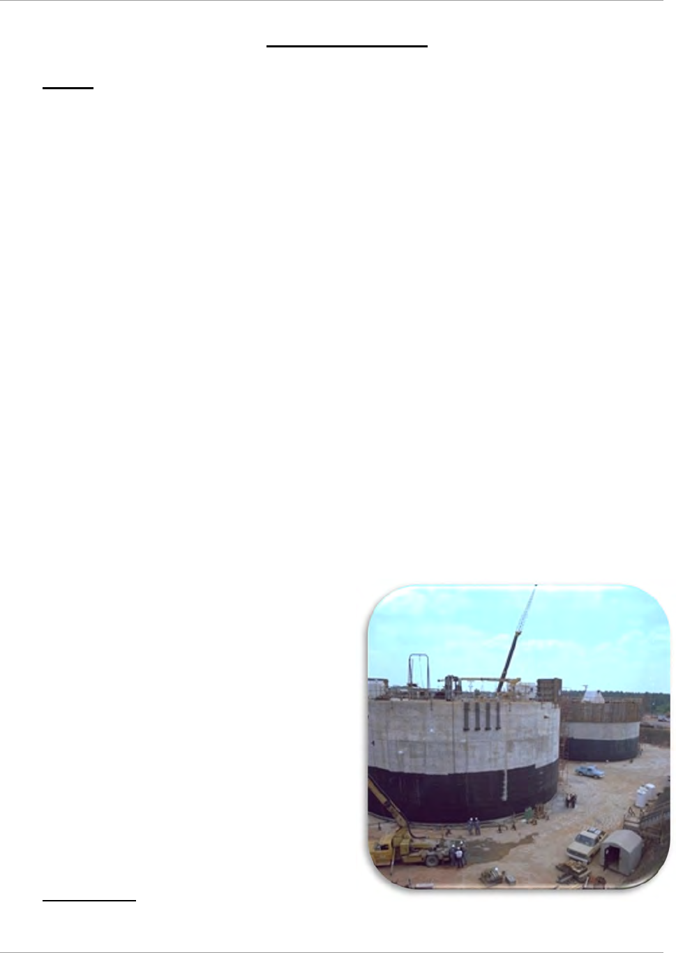
SRR-LWP-2009-00001 Liquid Waste System Plan
January 2019 Revision 21
System Description Page 30
6. System Description
6.1 History
The LW System is the integrated series of facilities at SRS that safely manage the existing waste inventory and
disposition waste stored in the tanks into a final glass or grout form. This system includes facilities for storage,
evaporation, waste removal, pre-treatment, vitrification, and disposal.
Since it became operational in 1951, SRS, a 300-square-mile DOE Complex located in the State of South Carolina, has
produced nuclear material for national defense, research, medical, and space programs. The separation of fissionable
nuclear material from irradiated targets and fuels resulted in the generation of over 160 Mgal of radioactive waste. As
of December 2018, approximately 35 Mgal
21
of radioactive waste are currently stored onsite in large underground waste
storage tanks at SRS. Most of the tank waste inventory is a complex mixture of chemical and radioactive waste
generated during the acid-side separation of special nuclear materials and enriched uranium from irradiated targets and
spent fuel using the Plutonium Uranium Reduction Extraction (PUREX) process in F-Canyon and the modified PUREX
process in H-Canyon (HM process). Waste generated from the recovery of Pu-238 in H-Canyon to produce heat sources
for space missions is also included. The waste was converted to an alkaline solution; metal oxides settled as sludge,
and supernate evaporated to form saltcake.
The variability in both nuclide and chemical content occurred because waste streams from the 1
st
cycle (high heat) and
2
nd
cycle (low heat) extractions from each Canyon were stored in separate tanks to better manage waste heat generation.
When these streams were neutralized with caustic, the resulting precipitate settled into four characteristic sludges
presently found in the tanks where they were originally deposited. The soluble portions of the 1
st
and 2
nd
cycle waste
were similarly partitioned but have and continue to undergo blending during waste transfer and staging of salt waste
for evaporative concentration to supernate and saltcake. Historically, fresh waste receipts were segregated into four
general categories in the SRS Tank Farms: PUREX high activity waste, PUREX low activity waste, HM high activity
wastes and HM low activity wastes. Because of this segregation, settled sludge solids contained in tanks that received
fresh waste are readily identified as one of these four categories. Fission product concentrations are about three orders
of magnitude higher in both PUREX and HM high-activity waste sludges than the corresponding low-activity waste
sludges.
Because of differences in the material processed by PUREX and HM processes, the chemical compositions of principal
sludge components (iron, aluminum, uranium, manganese, nickel, mercury, and noble metals) also vary over a broad
range between these sludges. Combining and blending salt solutions has tended to reduce soluble waste into blended
salt and concentrate, rather than maintaining four distinct salt compositions. Continued blending and evaporation of the
salt solution deposits crystallized salts with overlying and
interstitial concentrated salt solution in salt tanks located in
both Tank Farms. More recently, with transfers of sludge
slurries to sludge washing tanks, removal of saltcake for tank
removal from service, receipts of DWPF recycle, and space
limitations restricting full evaporator operations, salt
solutions have been transferred between the two Tank Farms.
Intermingling of PUREX and HM salt waste will continue
through the end of the program.
Continued long-term storage of these radioactive wastes
poses a potential environmental risk. Therefore, since 1996,
DOE and its contractors have been removing waste from
tanks, pre-treating it, vitrifying it, and pouring the vitrified
waste into canisters for long-term disposal in a permanent
canister storage location (see Figure 6-2—Process
Flowsheet). As of January 1, 2019, DWPF had poured 4,179
vitrified waste canisters (see Figure 6-3—Liquid Waste
Program—Current Status).
6.2 Tank Storage
SRS has 51 underground waste storage tanks, all of which were placed into operation between 1954 and 1986. There
are four types of waste tanks—Types I through IV. Type III tanks are the newest tanks, placed into operation between
Tanks under construction. Note tank size relative
to construction workers. Later, dirt is backfilled
around the tanks to provide shielding

Liquid Waste System Plan SRR-LWP-2009-00001
Revision 21 January 2019
Page 31 System Description
1969 and 1986. There are 27 Type III tanks. Type I tanks are the oldest tanks, constructed in 1952 through 1953. Type
II waste tanks were constructed in 1955 through 1956. There are eight Type IV tanks, constructed in 1958 through
1962. Four Type IV tanks, Tanks 17 through 20; three Type I tanks, Tank 5 and Tank 6 in FTF and Tank 12 in HTF;
and one Type II tank, Tank 16 in HTF have been isolated, grouted, and operationally closed. Fourteen tanks without
full secondary containment have a history of leakage
22
. Because of program progress to date, of these 14 SRS tanks (all
old-style tanks) with leakage history:
● 6 are operationally closed and grouted (Tanks 5, 6, 12, 16, 19, and 20)
● 2 are supporting the TCCR process (Tanks 10 and 11)
● 1 is awaiting heel removal activities to commence (Tank 15)
● 3 contain essentially dry waste, with little or no free liquid supernate (Tanks 1, 9, and 14)
● 2 contain liquid at a level below known leak sites (Tanks 4 and 13)
Of the remaining 10 old-style tanks (none of which have any known leakage history):
● 2 are operationally closed and grouted (Tanks 17 and 18)
● 2 contain essentially dry waste, with little or no free liquid supernate (Tanks 2 and 3)
● 6 contain liquid supernate. (Tanks 7, 8, and 21 through 24)
When waste disposition began in 1996, the inventory of waste in the SRS
tank system contained approximately 550 Million curies. Currently, 35
Mgal of radioactive waste, containing 248 million curies (MCi)
21
of
radioactivity, are stored in 43 active waste storage tanks located in two
separate locations, H-Tank Farm (27 tanks) and F-Tank Farm (16 tanks).
This waste is a complex mixture of insoluble metal hydroxide solids,
commonly referred to as sludge, and soluble salt supernate. The
supernate volume is reduced by evaporation, which also concentrates the
soluble salts to their solubility limit. The resultant solution crystallizes as
salts. The resulting crystalline solids are commonly referred to as
saltcake. The saltcake and supernate combined are referred to as salt
waste.
The sludge component of the radioactive waste represents approximately
2.8 Mgal (8% of total) of waste but contains approximately 116 MCi
(47% of total). The salt waste makes up the remaining 32.2 Mgal (92%
of total) of waste and contains approximately 132 MCi (53% of total).
Of that salt waste, the supernate accounts for 16.2 Mgal and 120 MCi
and saltcake accounts for the remaining 16.0 Mgal and 12 MCi
21
. The
sludge contains the majority of the long-lived (half-life > 30 years)
radionuclides (e.g., actinides) and strontium. The sludge is currently
being stabilized in DWPF through a vitrification process that
immobilizes the waste in a borosilicate glass matrix. The salt is being
separated in the ARP/MCU process into a higher-level component being
stabilized in DWPF and a
lower level component being
dispositioned in SDF.
Radioactive waste volumes
and radioactivity inventories
reported herein are based on
the Waste Characterization
System (WCS) database,
which includes the chemical and radionuclide inventories on a tank-by-tank
basis. WCS is a dynamic database frequently updated with new data from
ongoing operations such as decanting and concentrating of free supernate via
evaporators, preparation of sludge batches for DWPF feed, waste transfers
between tanks, waste sample analyses, and influent receipts such as
H-Canyon waste and DWPF recycle.
Salt waste is dissolved in the liquid portion of the
waste. It can be in normal solution as Supernate (top
picture) or, after evaporation, as salt cake (bottom
picture) or concentrated supernate. The pipes in all
the pictures are cooling coils.
Sludge consists of insoluble solids that settle to the
bottom of a tank. Note the offgas bubbles,
including hydrogen generated from radiolysis.
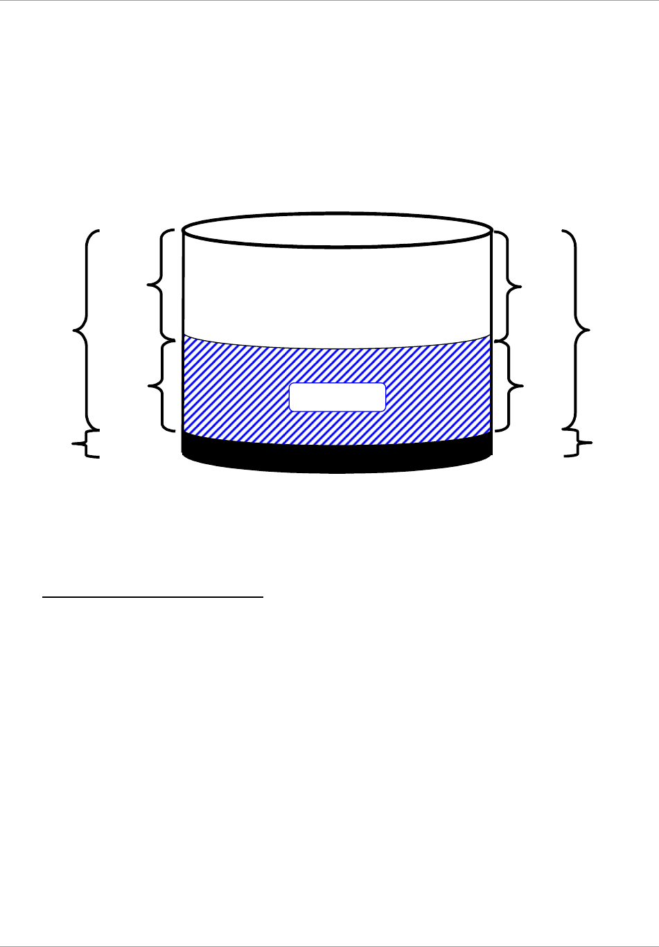
SRR-LWP-2009-00001 Liquid Waste System Plan
January 2019 Revision 21
System Description Page 32
Well over 95%
21
of the salt waste radioactivity is short-lived (half-life ≤ 30 years) Cs-137 and its daughter product, Ba-
137m, along with lower levels of Sr
90
actinide contamination. Depending on the waste stream (e.g., canyon waste,
DWPF recycle waste), the cesium concentration may vary. The precipitation of salts following evaporation can also
change the cesium concentration. The concentration of cesium is significantly lower than non-radioactive salts in the
waste, such as sodium nitrate and nitrite, therefore, the cesium does not reach its solubility limit and only a small
fraction precipitates
23
. As a result, the cesium concentration in the saltcake is much lower than that in the liquid
supernate and interstitial liquid fraction of the salt waste.
Figure 6-1—Waste Tank Composite Inventory (as of December 31, 2018)
21
6.3 Waste Tank Space Management
To make better use of available tank storage capacity, incoming LW is evaporated to reduce its volume. This is
important because most of the SRS Type III waste storage tanks are already near full capacity. Since 1954, the Tank
Farms have received over 160 Mgal of LW, of which over 110 Mgal have been evaporated, leaving approximately 35
Mgal in the storage tanks. Projected available tank space is carefully tracked to ensure that the Tank Farms do not
become “water logged,” meaning that so much of the usable Type III tank space has been filled that normal operations
and waste removal and processing operations cannot continue. A contingency allotment of 1.3 Mgal is not included as
working space. This amount is equivalent to the size of the largest tank and is reserved for the unlikely event that a full
tank failed such that all its material had to be removed. Waste receipts and transfers are normal Tank Farm activities as
the Tank Farms receive new or “fresh” waste from the H-Canyon stabilization program, LW from DWPF processing
(typically referred to as “DWPF recycle”), and wash water from sludge washing. The Tank Farms also make routine
transfers to and from waste tanks and evaporators. Since initiation of interim salt waste treatment (DDA and
ARP/MCU), the working capacity of the Tank Farms has been maintained. Two evaporator systems are currently
operating at SRS—the 2H and 3H systems.
Space in new-style tanks is used for various operations for waste processing and disposal. Tank space is recovered
through evaporator operations, DWPF vitrification, ARP/MCU treatment, and Saltstone disposal. This valuable space
has been used to: (1) retrieve waste from and clean old-style tanks; (2) prepare, qualify, and treat sludge waste for
disposal; (3) prepare, qualify, treat, and dispose salt waste; and (4) support nuclear materials stabilization and disposal
in H-Canyon through 2030. The Tank Farm space management strategy is based on a set of key assumptions involving
projections of DWPF canister production rates, influent stream volumes, Tank Farm evaporator performance, and space
gain initiative implementation. The processing of salt and sludge utilizes existing tank space to retrieve and prepare
Volume
35.0 Million
Gallons (Mgal)
Curies
132 MCi
(53%)
116 MCi
(47%)
248 Million
Curies (MCi)
120 MCi
(48%)
32.2 Mgal
(92%)
2.8 Mgal
(8%)
16.2 Mgal
(46%)
12 MCi
(5%)
16.0 Mgal
(46%)
Sludge
Salt Supernate
Saltcake
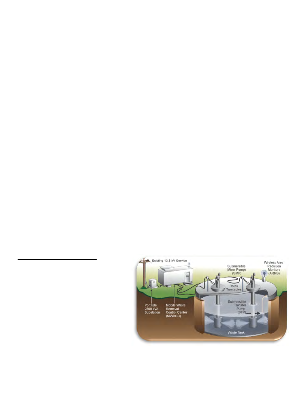
Liquid Waste System Plan SRR-LWP-2009-00001
Revision 21 January 2019
Page 33 System Description
waste. Sludge processing through DWPF removes the highest risk material from the old-style tanks. However, for every
gallon of sludge processed, 1.3 gallons of salt waste is formed due to sludge washing and DWPF processing operations
to return the resulting low-level salt waste to the Tank Farm. Similarly, salt waste retrieval, preparation, and batching
typically require the use of three gallons of tank space per gallon of salt waste treated. Given these parameters, the “key
to reducing the overall risk is processing high-level waste as expeditiously as possible and managing the total tank
space efficiently,” as recognized by the DNFSB letter dated January 7, 2010
24
.
New-style tank space is a currency used to prepare for permanent immobilization and disposition of HLW in a vitrified
waste form and low-level waste in a grouted waste form. Additionally, several “old-style” tanks support immobilization
and disposition of high-level waste. The tank space management program maintains sufficient space to allow continued
DWPF operations. The tank space management program also provides the necessary tank space to support staging of
salt solutions to sustain salt waste disposition currently through ARP/MCU and subsequently through SWPF. Of the
27 new-style tanks (with a total nominal volume of 35.1 million gallons) in the SRS LW System:
● 5 (Tanks 38, 41, 43, 49, and 50) are dedicated to salt batching, qualification, and disposition (including DWPF
recycle beneficial reuse, feeding the Saltstone Production Facility (SPF), and the 2H Evaporator);
● 2 additional tanks (Tanks 27 and 42) are planned for conversion to salt blend tanks to prepare salt batching
● 6 (Tanks 29, 30, 32, 37, 40, and 51) are dedicated to sludge batching, qualification, and disposition (including
the 3H Evaporator)
● 1 (Tank 39) is dedicated to uninterrupted H-Canyon waste receipts
● 13 (Tanks 25, 26, 28, 31, 33, 34, 35, 36, 44, 45, 46, 47, and 48) are dedicated to safe storage of legacy LW
pending retrieval and disposition.
As the Plan progresses, the tank function changes.
There are currently ~8.2 Mgal of empty space (~23%) in these new-style tanks:
● 3.0 Mgal is margin as defense-in-depth operational control coupled with Safety Class or Safety Significant
(SC/SS) structures, systems, or components (SSC) to facilitate reasonably conservative assurance of more than
adequate dilution and ventilation of potentially flammable vapors
● 1.3 Mgal is procedurally-required minimum contingency space for recovery from the unlikely event of a bulk
waste leak elsewhere in the system
● 3.9 Mgal is operational “working” space variously used to provide:
— Additional contingency transfer space as operational excess margin above the procedurally-required
minimum
— Excess margin to preserve salt batch quality and maintain uninterrupted treatment and disposition through
ARP/MCU and Saltstone
— Excess margin to preserve sludge batch quality and maintain uninterrupted immobilization through DWPF
— Excess margin to preserve uninterrupted support for H-Canyon.
6.4 Waste Removal from Tanks
The first step in the disposition of sludge and salt waste
is waste removal. Sludge is removed from the tank and
transferred to a sludge hub tank or feed preparation
tank ensuring sludge waste is continuously available
for treatment at DWPF. Salt is dissolved, removed, and
staged for treatment at ARP/MCU, TCCR, or SWPF.
If permanent infrastructure is available, sludge
removal planning maximizes the use of this
infrastructure to most effectively remove waste. This
planning includes the use of structural steel, cable
trays, existing slurry pumps, transfer pumps, and
ventilation. However, to reduce the two-to-four-year
period required for installation of substantial structural steel and large mixing and transfer pumps—with their attendant
infrastructure—required for waste removal, a temporary waste removal equipment innovation was developed. This
concept minimizes new infrastructure. Portable and temporary equipment meet tank infrastructure needs. Additional
purchased pumps and equipment perform accelerated waste removal operations concurrently in both Tank Farms. The
primary components of the temporary system are:
Temporary Waste
Removal E
q
ui
p
ment

SRR-LWP-2009-00001 Liquid Waste System Plan
January 2019 Revision 21
System Description Page 34
● Reusable mixing pumps
● A portable field operating station containing pump drives and controls
● A portable substation to provide 480-, 240- and 120-volt power
● Disposable commercial transfer pumps
The equipment is deployed at the tank as a field operating station, providing temporary power and control for waste
removal equipment. When waste removal is completed on one tank, the equipment may be reconfigured to support
waste removal on the next tank. Pumps are sized to fit through existing 24-inch riser openings in the waste tanks. To
the extent that risers are available, pumps are set in optimal configurations within the waste tanks. Product lubricated
bearings and motor cooling eliminate the need for bearing and seal water supply. These pumps have exterior fittings
and fixtures, so the pumps can be decontaminated, minimizing radiation exposure to personnel during relocation to
another tank. Disposable transfer pumps transfer the waste to a receipt or hub tank using existing underground transfer
lines and diversion boxes. If the transfer system is degraded or non-existent, above-grade hose-in-hose technology is
deployed, rather than investing in costly repairs. Temporary shielding is supplied as necessary to reduce exposure to
personnel.
6.5 Safe Disposal of the Waste
The goal is to convert the majority of the waste into one of two final waste forms: glass, which will contain over 99%
of the radioactivity, and saltstone, which will contain most of the volume. Each of the waste types at SRS needs to be
treated to accomplish disposal in these two waste forms. The sludge must be washed to remove non-radioactive salts
that would interfere with glass production. The washed sludge can then be sent to DWPF for vitrification. The salt must
be treated to separate the bulk of the radionuclides from the non-radioactive salts in the waste. Starting in 2020, this
separation will be accomplished in SWPF. However, until the startup of SWPF, ARP/MCU accomplishes this
separation. ARP/MCU and SWPF will be supplemented with TCCR processing to accelerate the disposition of salt
waste
6.6 Salt Processing
Five different processes treat salt:
● Deliquification, Dissolution, and Adjustment (DDA) –Deliquification (i.e., extracting the interstitial liquid)
is an effective decontamination process because the primary radionuclide in salt is Cs-137, which is highly
soluble. To accomplish the process, the salt was first deliquified by draining and pumping. The deliquified
salt was then Dissolved by adding water and pumping out the salt solution. The resulting salt solution was
aggregated with other Tank Farm waste to Adjust batch chemistry for processing at SPF. For salt in Tank 41
as of June 9, 2003, which was relatively low in radioactive content, treatment using DDA-solely was
sufficient to meet the SPF WAC. Tank 41 has since received additional salt dissolution from Tank 25 and
there is no longer any qualified feed for the DDA-solely process. No further DDA-solely treatment is
planned.
● Actinide Removal Process (ARP) – For salt, even though extraction of the interstitial liquid reduces Cs-137
and soluble actinide concentrations, the Cs-137 or actinide concentrations of the resulting salt are too high to
meet the SPF WAC. In ARP, MST may be added to the waste as a finely divided solid. Actinides are sorbed
on the MST and then filtered out of the liquid to produce a low-level waste stream that is sent to MCU. The
solids, containing the MST with the actinides, are dispositioned at DWPF. In 2016, a demonstration of ARP
was initiated to demonstrate that, with the correct salt batch makeup, MST addition is not necessary to meet
the SPF WAC for the ARP/MCU batches.
● Modular CSSX Unit (MCU) – The ARP low-level waste stream requires reduction in the concentration of
Cs-137 using the CSSX process. MCU is a solvent extraction process for removal of Cs-137 from caustic salt
solutions. The solvent used is a four-part solvent with the key ingredient being the cesium extractant
(previously BoBCalix but, beginning September 2013, the NGS is MaxCalix). This solvent is fed to a bank of
centrifugal contactors while the waste is fed to the other end in a counter-current flow. The solvent extracts
the cesium, with each successive contactor stage extracting more, resulting in a DSS stream and a cesium-
laden solvent stream. The solvent stream is stripped of its cesium, washed, and the solvent is reused. The
cesium-laden SE is transferred to DWPF. MCU has a dual purpose:
— demonstrating the CSSX flowsheet
— treating salt waste to enable accelerated closure of Type I, II, and IV tanks and uninterrupted vitrification
of HLW at DWPF
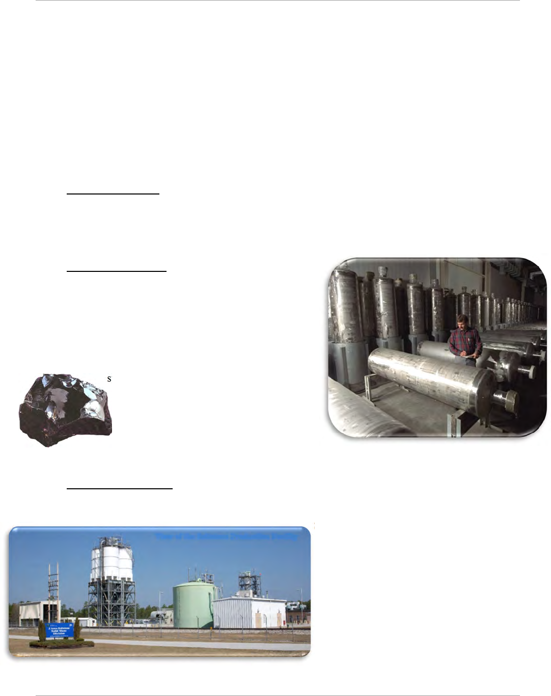
Liquid Waste System Plan SRR-LWP-2009-00001
Revision 21 January 2019
Page 35 System Description
● Salt Waste Processing Facility (SWPF) – This is the full-scale CSSX process. This planned facility will
incorporate both the ARP and CSSX processes in a full-scale shielded facility capable of handling salt with
higher levels of radioactivity.
● Tank Closure Cesium Removal (TCCR) – This consists of an ion exchange process for the removal of cesium
from liquid salt waste to provide supplemental treatment capability. Building on the experience of modular
commercial nuclear plant decontamination and following the disaster response associated with Fukushima,
technology exists to efficiently accomplish large scale, selective removal of the cesium component of the bulk
salt waste. The configuration is an “at-tank” modular arrangement. The configuration consists of temporary
process structures located near a tank, so the cesium removal process would take place outside of the tank. The
DSS will be transferred to Tank 50 for disposition via SPF. Once the ion exchange media in a column becomes
loaded with cesium to the extent practical (“spent”), the column (with media) will be removed from the system
and replaced with a new ion exchange column loaded with fresh media. The spent column will be transported
to an ISS location within the tank farm.
6.7 Sludge Processing
Sludge is washed to reduce the amount of non-radioactive soluble salts remaining in the sludge slurry. During sludge
processing, large volumes of wash water are generated and must be volume-reduced by evaporation or beneficially
reused. Over the life of the waste removal program, the sludge currently stored in tanks at SRS will be blended into
separate sludge batches to be processed and fed to DWPF for vitrification.
6.8 DWPF Vitrification
Final processing for the washed sludge and salt waste occurs at
DWPF. This waste includes MST/sludge from ARP or SWPF, the
cesium SE from MCU or SWPF, and the washed sludge slurry. In
a complex sequence of carefully controlled chemical reactions, this
waste is blended with glass frit and melted to vitrify it into a
borosilicate glass form. The resulting molten glass is poured into
stainless steel canisters. As the filled canisters cool, the molten
glass solidifies, immobilizing the radioactive waste within the glass
structure. After a canister has cooled, it is sealed
with a temporary plug, the external surfaces
are decontaminated to meet United States
Department of Transportation requirements,
and the canister is then permanently sealed. The
canister is then ready to be stored on an interim
basis on-site. A low-level recycle waste stream from
DWPF is returned to the Tank Farms. DWPF has been operational since 1996.
6.9 Saltstone Disposition
The Saltstone Facility, located in Z-Area, consists of two facility segments: the Saltstone Production Facility (SPF) and
the Saltstone Disposal Facility (SDF). SPF is permitted as a wastewater treatment facility per SCDHEC regulations.
SPF receives and treats the salt solution to produce
grout by mixing the LLW liquid stream with
cementitious materials (cement, flyash, and
slag). A slurry of the components is pumped into
Saltstone Disposal Units (SDU), located in SDF,
where the grout solidifies into a monolithic,
non-hazardous, solid LLW form known as
saltstone. SDF is permitted as an Industrial Solid
Waste Landfill site.
Future salt waste processing will impose
significantly greater production demands. After
SWPF startup, feed of DSS to the SPF could reach
as high as 12.8 Mgal/yr. In anticipation of this future demand, SRS completed installation of Enhanced Low Activity
Waste Disposal (ELAWD) improvements. The ELAWD Phase 1 improvements provided equipment modifications to
Sample of Vitrified
Radioactive Glass
Canisters being received
(prior to being filled with radioactive glass)
View of the Saltstone Production Facility
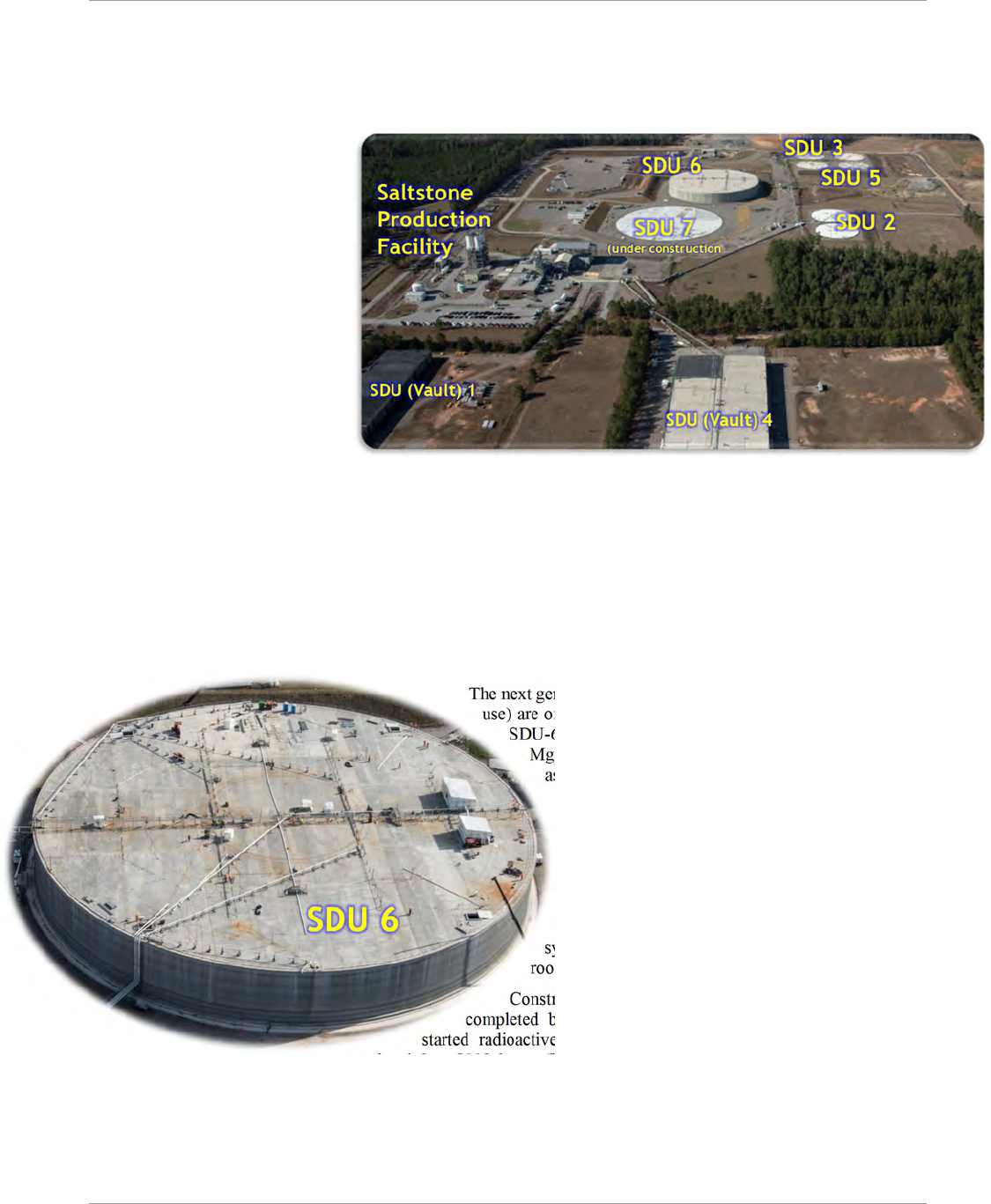
SRR-LWP-2009-00001 Liquid Waste System Plan
January 2019 Revision 21
System Description Page 36
increase operating margins, reliability, and controls. Also, during the ELAWD Phase 1 outage, the Mixing and Transfer
System was modified to connect SPF to SDU-2.
ELAWD Phase 2 will modify the dry feeds system and connect SPF to new larger capacity salt solution feed receipt
tanks. Lastly, modifications that support converting from the present day-shift staffing to 24/7 operations are planned.
The SDF will contain several large
concrete SDUs. Each of the SDUs
will be filled with saltstone. The
grout itself provides primary
containment of the waste, and the
walls, floor, and roof of the SDUs
provide secondary containment.
Approximately 15 feet of
overburden were removed to
prepare and level the site for SDU
construction. All SDUs will be built
at or slightly below the grade level
that exists after the overburden and
leveling operations are complete.
The bottom of the saltstone
monoliths will be at least five feet
above the historic high-water table beneath the Z-Area site, thus avoiding disposal of waste in a zone of water table
fluctuation. Run-on and run-off controls are installed to minimize site erosion during the operational period.
The first SDU (Vault 1), ~100 feet by 600 feet by 25 feet high, is divided into six cells. The second SDU (Vault 4),
~200 feet by 600 feet 26 feet high, has twelve cells. No more waste disposal is planned for these SDUs.
SDU-2 and SDU-5 (which are full), and SDU-3 have two cells, each being 150 feet diameter by 22 feet high. This
design is used commercially for storage of water. After accounting for interior obstructions (support columns,
drainwater collection systems, etc.), the nominal useable volume of a cell is 2.8 Mgal. Recent operating experience
averages 1.76 gallons of grout produced for each gallon of feed, yielding a nominal cell capacity of approximately 1.6
Mgal of feed.
The next generation of units, beginning with SDU-6 (which is in
use) are of a 375-foot diameter 43-foot tall single-cell design.
SDU-6, can hold 32 Mgal of contaminated grout or 18.7
Mgal of feed. Future SDUs will have the same capacity
as SDU-6. The last SDU will be sized as needed to
complete the LW mission.
Closure operations will begin near the end of the
active disposal period in the SDF, i.e., after most or
all the SDUs have been constructed and filled.
Backfill of native soil will be placed around the
SDUs. The present closure concept includes two
moisture barriers consisting of clay/gravel drainage
systems along with backfill layers and a shallow-
rooted bamboo vegetative cover.
Construction of the SDF and the first two vaults were
completed between February 1986 and July 1988. The SDF
started radioactive operations June 12, 1990. SDU-2, construction
complete it June 2012, began filling in September 2012 and completed filling in July
2014. SDU-3 and SDU-5 were construction complete in September 2013. SDU-5 began filling in December 2013 and
completed filling in February 2017. SDU-3 began filling in February 2017. The large SDU-6 construction began in
December 2013, was completed in June 2018 and began filling in August 2018. Future SDUs will be constructed on a
“just-in-time” basis in coordination with salt processing production rates.
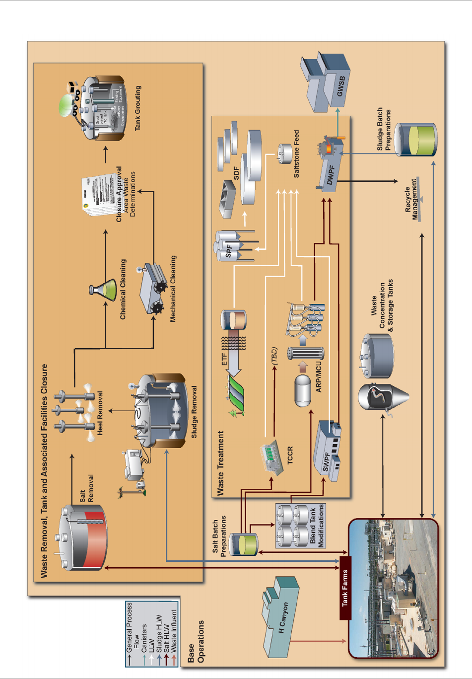
Liquid Waste System Plan SRR-LWP-2009-00001
Revision 21 January 2019
Page 37 System Description
Figure 6-2—Process Flowsheet
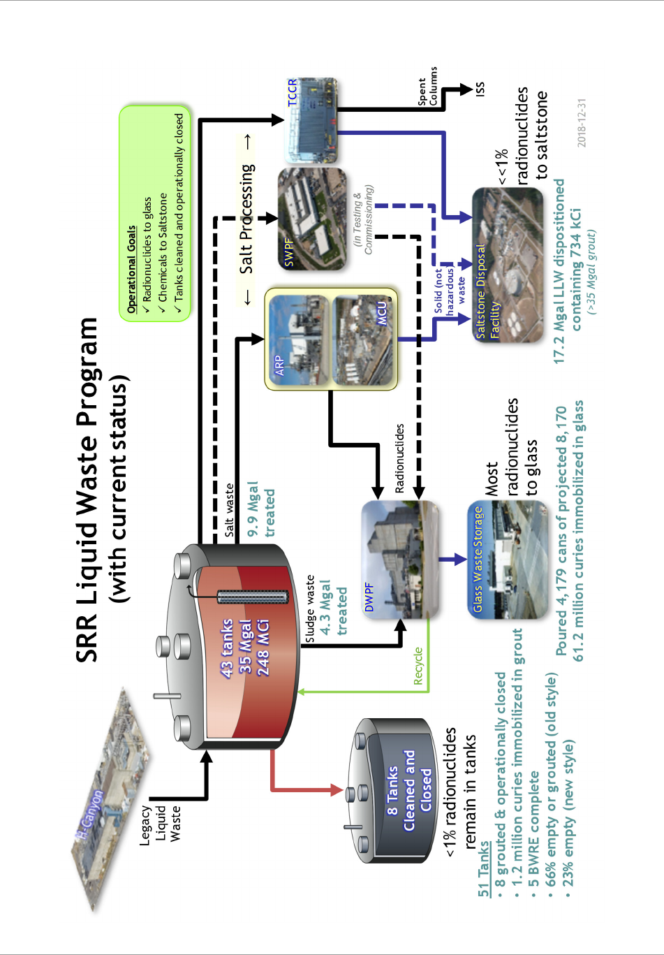
SRR-LWP-2009-00001 Liquid Waste System Plan
January 2019 Revision 21
System Description Page 38
Figure 6-3—Liquid Waste Program—Current Status
w
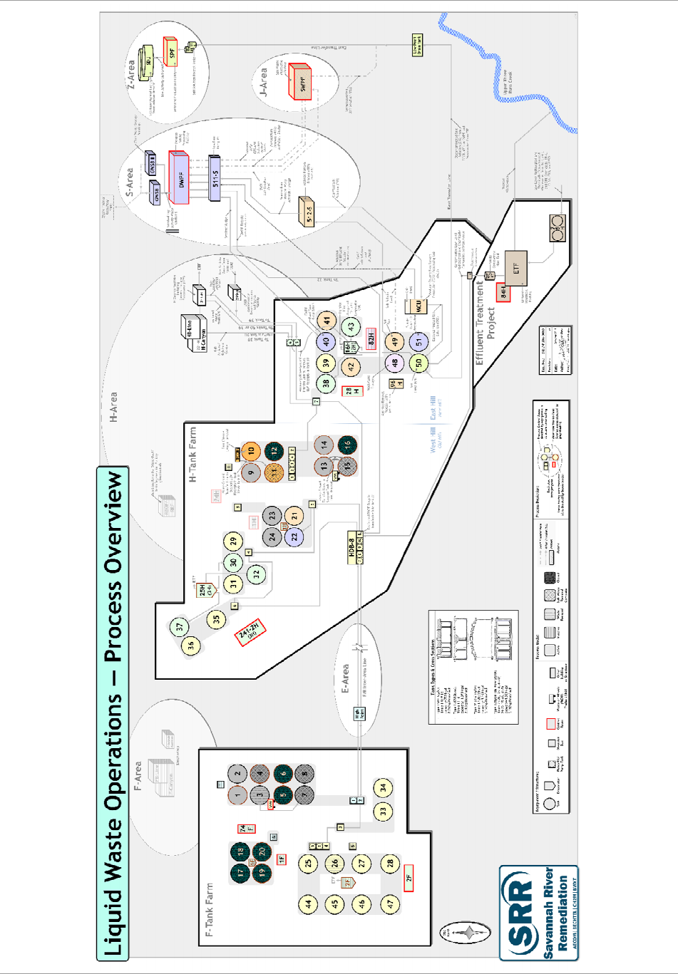
Liquid Waste System Plan SRR-LWP-2009-00001
Revision 21 January 2019
Page 39 System Description
Figure 6-4—Liquid Waste Process Overview

SRR-LWP-2009-00001 Liquid Waste System Plan
January 2019 Revision 21
System Description Page 40
Salt Solution (kgal)
Saltstone Feed to Tank 50 (kgal)
b
DDA-solely ARP/MCU TCCR-1 TCCR-2 SWPF
Total
a
DSS H-Can 512-S ETP
Total as of
end of FY10
2,800 985 3,785 3,151 682 3,019 3,881 4
FY11 1,064 1,064 1,487 200 64 1,487 4
FY12 705 705 901 19 24 1,252 4 & 2
FY13 1,320 1,320 1,566 24 65 69 2,005 2
FY14 551 551 697 15 12 47 1,167 2 & 5
FY15 753 753 919 12 18 45 828 5
FY16 1,126 1,126 1,429 11 9 42 1,506 5
FY17 397 397 442 5 5 46 500 5
FY18 149 149 171 11 3 19 384 5–6
FY19 900 625 1,525 1,767 15 10 50 1,842 5–6
FY20 100 2,500 2,600 3,331 2 50 3,383 6
FY21 - 1,000 7,250 8,250 10,291 50 10,341 6
FY22 1,000 1,000 9,000 11,000 13,534 50 13,584 6–7
FY23 1,000 9,000 10,000 12,534 50 12,584 7–8
FY24 1,000 1,000 9,000 11,000 13,534 188 13,721 8
FY25 1,000 1,000 9,000 11,000 13,534 188 13,721 8–9
FY26 1,000 9,000 10,000 12,534 188 12,721 9–10
FY27 1,000 1,000 9,000 11,000 13,534 188 13,721 10
FY28 1,000 1,000 9,000 11,000 13,534 188 13,721 10–11
FY29 1,000 1,000 6,000 8,000 9,689 147 9,836 11–12
FY30 500 500 9,000 10,000 12,534 188 13,132 12
FY31 2,250 2,250 2,883 155 3,038 12–13
FY32 -14414413
FY33 140 140 13
FY34 -95 95 13
Total 2,800 8,050 9,125 7,500 90,000 117,475 143,990 994 5,430 148,736
End of
Fiscal Year
SDU
Numbers
c
Feed
to SPF
Appendix A—Salt Solution Processing
Salt Solution
is a total of salt solution treated via the DDA-solely, ARP/MCU, TCCR, and SWPF processes. Each gallon of salt
solution treated via ARP/MCU yields ~1.26 gal of DSS, ~1.28 gallons for SWPF and ~1 gallon for TCCR.
LLW receipts to Tank 50 include the DSS from salt processing, LLW from HCanyon, ARP (512-S) filter cleaning discards, and the
ETP low level stream.
● SDU-2 and SDU-3 (being full), SDU1, and SDU4, are no longer planned to receive contaminated grout
● SDU5 has two ~2.8-Mgal cylindrical cells, each capable of receiving ~1.5 Mgal of feed
● SDU6 is a single 32 Mgal cylindrical cell, capable of receiving ~18.7 Mgal of feed
● Future SDUs are assumed to have a similar design to SDU-6. The last SDU will be sized for the remaining production.
● Each gallon of Tank 50 feed, when added to the cement, flyash, and slag, generates approximately 1.76 gallons of grout
● Bleed water recycling consumes 5% of the vault space, reducing the available space for feed solution.
Dates, volumes, and chemical or radiological composition information are planning approximations only.
a
b
c
Note
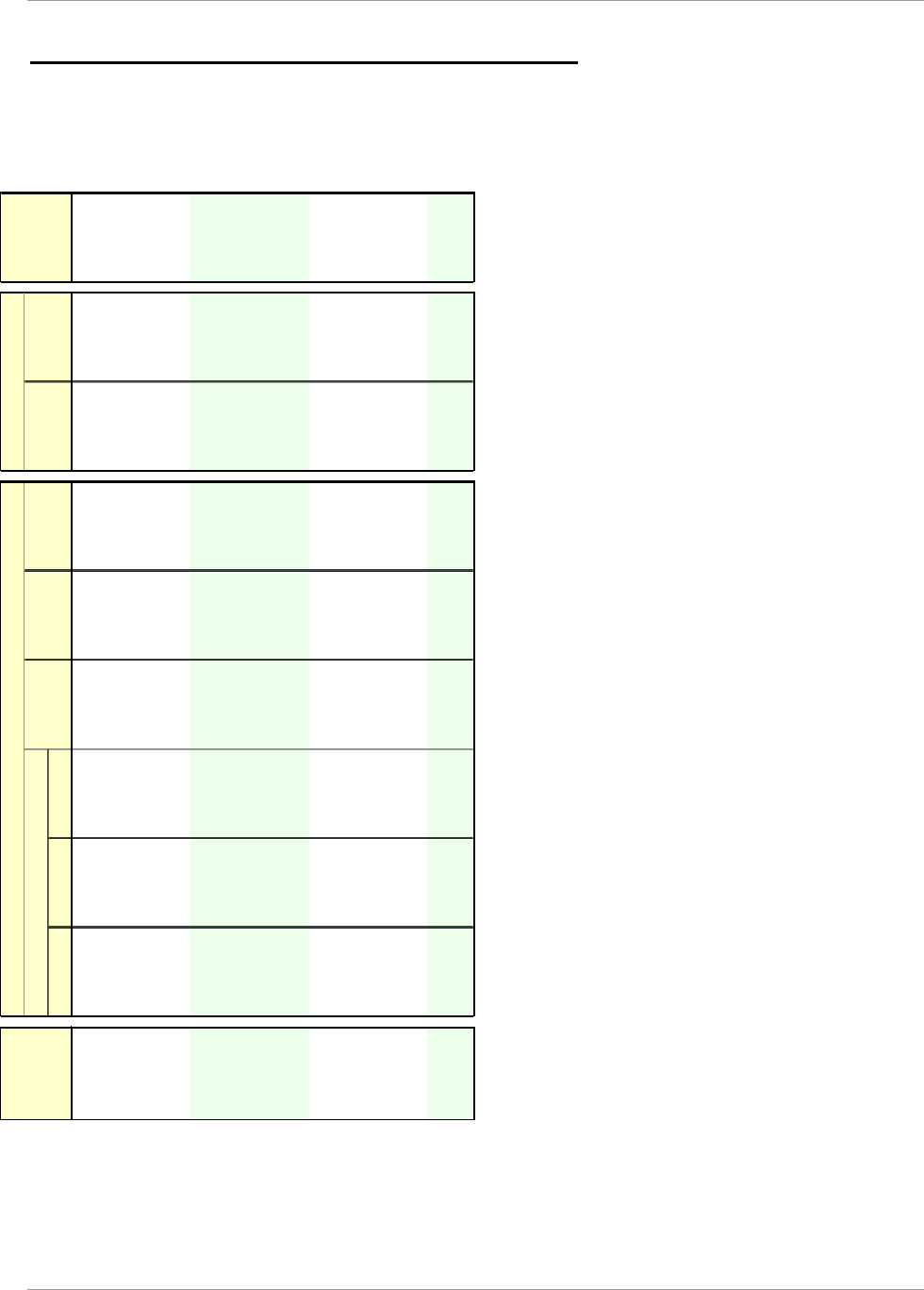
Liquid Waste System Plan SRR-LWP-2009-00001
Revision 21 January 2019
Page 41 Appendices
Effluents (kgal)
HLW LLW Other Mat'l
b
FY19 200 15 11 728 12 50 1,842 50 33,270
FY20 200 - - 1,022 12 50 3,383 74 32,252
FY21 200 - 2,171 12 50 10,341 202 29,913
FY22 200 - 2,752 12 50 13,584 309 28,041
FY23 300 - 1,376 12 50 12,584 307 24,481
FY24 300 - 12 188 13,721 307 21,938
FY25 300 - 12 188 13,721 317 20,795
FY26 300 - 12 188 12,721 312 18,929
FY27 300 - 12 188 13,721 308 16,406
FY28 300 12 188 13,721 301 11,828
FY29 300 12 147 9,836 206 9,358
FY30 300 12 188 13,132 313 4,367
FY31
d
155 3,038 373 2,875
FY32 144 144 393 2,636
FY33 140 140 356 544
FY34 95 95 104 406
FY35 - - - -
Feed to SPF
Sludge to
DWPF
Tota
l
Inventory
e
End of
Fiscal Year
Influents (kgal)
H-Canyon
a
D
W
P
F
Recycle
c
299-H ETP
Appendix B—Tank Farm Influents and Effluents
H-Canyon receipts consist mainly of: HLW, received into Tank 39 and LLW, received in Tank 50
Various nuclear materials, including plutonium, uranium, neptunium, etc., from H-Canyon may be introduced directly into
sludge batches, via either the sludge preparation tank (Tank 51) or the DWPF feed tank (Tank 40) to the extent allowable
without negatively impacting planned canister waste loadings while continuing to comply with the canister fissile material
concentration limits. The HCanyon forecast for these materials will be included in future versions of this Plan, as it is made
lbl
DWPF Recycle receipts may be received into Tank 22 or used for Beneficial Reuse in salt dissolution or sludge washing. After
FY23 DWPF recycle is planned to be treated by ETP.
Maintenance Facility (299-H) receipts mainly consists of dilute nitric acid stream, decontamination solutions, and steam
condensate. Waste streams from decontaminating equipment are collected in the 299-H pump tank, neutralized, and sent to
Tank 39. Beginning in FY31, 299-H services supported by H-Canyon will cease and maintenance activities will be performed
in the DWPF maintenance cell.
Volumes are not additive after accounting for jet dilution, expansion of sludge during sludge slurrying operations (sludge
becomes less dense), and other volume changes during the processing of waste. During a transfer, steam eductor jets are
used to transfer LW from tank to tank. Volume from the transfer steam accounts for 4% of the volume being transferred for
intra-area transfers and 6% for IAL. Additionally, mixing waste forms of different compositions are not mathematically
additive.
Dates, volumes, and chemical or radiological composition information are planning approximations only.
a
b
c
d
e
Note
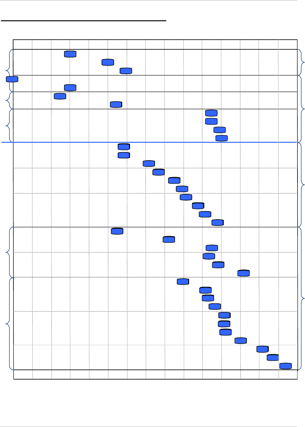
SRR-LWP-2009-00001 Liquid Waste System Plan
January 2019 Revision 21
Appendices Page 42
FY28 FY29 FY30 FY31 FY32 FY33FY20 FY21 FY22 FY23 FY24 FY25 FY26 FY27
Old Style TanksNew Style Tanks
Type IIType IV Type I
H-Tank Farm FTFH-Tank Farm F-Tank Farm
West HillEast Hill
14
13
9
10
48
3
2
1
47
45
46
25
44
27
26
28
34
33
23
21
24
22
29
30
31
32
36
35
38
43
49
42
41
39
50
51
40
FY28 FY29 FY30 FY31 FY32 FY33FY20 FY21 FY22 FY23 FY24 FY25 FY26 FY27
FY34
FY34
37
Appendix C—Bulk Waste Removal Complete
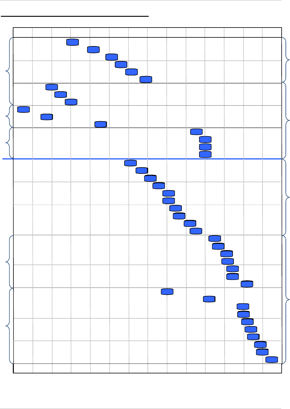
Liquid Waste System Plan SRR-LWP-2009-00001
Revision 21 January 2019
Page 43 Appendices
FY28 FY29 FY30 FY31 FY32 FY33
FY34 FY35 FY36 FY37
FY24 FY25 FY26 FY27
15
FY28 FY29 FY30 FY31 FY32 FY33
FY34 FY35 FY36 FY37
FY24 FY25 FY26 FY27
Old Style TanksNew Style Tanks
Type IIType IV Type I
H-Tank Farm F-Tank FarmH-Tank Farm F-Tank Farm
West HillEast Hill
14
13
9
10
11
48
3
2
1
4
7
8
47
45
46
25
27
44
26
28
34
33
23
21
24
22
29
30
31
32
36
37
35
38
43
49
42
41
39
50
51
40
Appendix D—Tank Removal from Service

SRR-LWP-2009-00001 Liquid Waste System Plan
January 2019 Revision 21
Appendices Page 44
Appendix E—LW System Plan—Revision 21 Summary
(see attached foldout chart)

Liquid Waste System Plan SRR-LWP-2009-00001
Revision 21 January 2019
Page 45 Appendices
Source
Tanks
a
Projected
SOL
(weight %)
Actual Cans
@ Projected
SOL
Date Batch
Finished @
Projected SOL
b
Actual canisters poured through December 2018 (SB 1 through 9): 4,179
SB9 (con't)
13, 12 Chemical Cleaning,
22 (solids from DWPF)
32% 272 Jun 2021
SB10
15 via 13 (HM HAW), LTAD,
26 (PUREX), AFS-2 (Pu)
36% 500 Feb 2023
SB11
15 via 13 (HM HAW), 35 (HM HAW),
LTAD, 26, 34 (PUREX)
36% 450 Aug 2024
SB12 35, 39 (HM HAW), LTAD 34 (PUREX) 36% 425 Jan 2026
SB13
35, 39 (HM HAW), LTAD, 33 (PUREX),
11 &14 via 13 (MIXED HM/PUREX)
36% 450 Jul 2027
SB14
35 & 39 (HM HAW), LTAD,
47 via 33 (PUREX)
36% 425 Dec 2028
DWPF Melter Replacement — January 2029 thru April 2029
SB15
35, 39, 32 (HM HAW), LTAD,
43 (MIXED HM HAW/LAW),
4, 7, 8, & 47 via 33 (PUREX)
36% 300 Apr 2030
SB16 32, 33, 35, 39 (HM HAW) 40% 375 Jul 2031
Heel Batch 1
c
39, 32 (HM HAW)(incl 23 Solids),
33 (PUREX)
40% 375 Oct 2032
Heel Batch 2
c
35 (HM HAW plus DWPF Solids),
39 (Incl 32 HM HAW, 24 Zeolite, 23 Solids),
43H (HM LAW)
40% 260 Sep 2033
Heel Batch 3
c
43, 35, 39 including Heels
(Mixed HM HAW, HM LAW)
32% 60 Mar 2034
Heel Batch 4
c
40 Heel Material 28% 50 Sep 2034
Total: 8,121
a
b
c
Note:
Sludge Batch
The indicated tanks are the sources of the major components of each
sludge batch, not necessarily the sludge location just prior to receipt for
sludge washing. Tanks 33 and 35, for example, are also used to stage
sludge that is removed from other tanks. Some BWRE may be accelerated
with respect to this table as conditions dictate.
Dates are approximate and represent when Tank 40 gets to heel level.
Actual dates depend on canister production rates
Longer processing assumed for dilute heel processing
Dates, volumes, and chemical or radiological composition information are
planning approximations only.
Appendix F—Sludge Processing
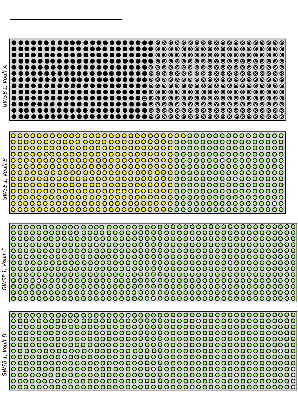
SRR-LWP-2009-00001 Liquid Waste System Plan
January 2019 Revision 21
Appendices Page 46
Appendix G—GWSB Utilization
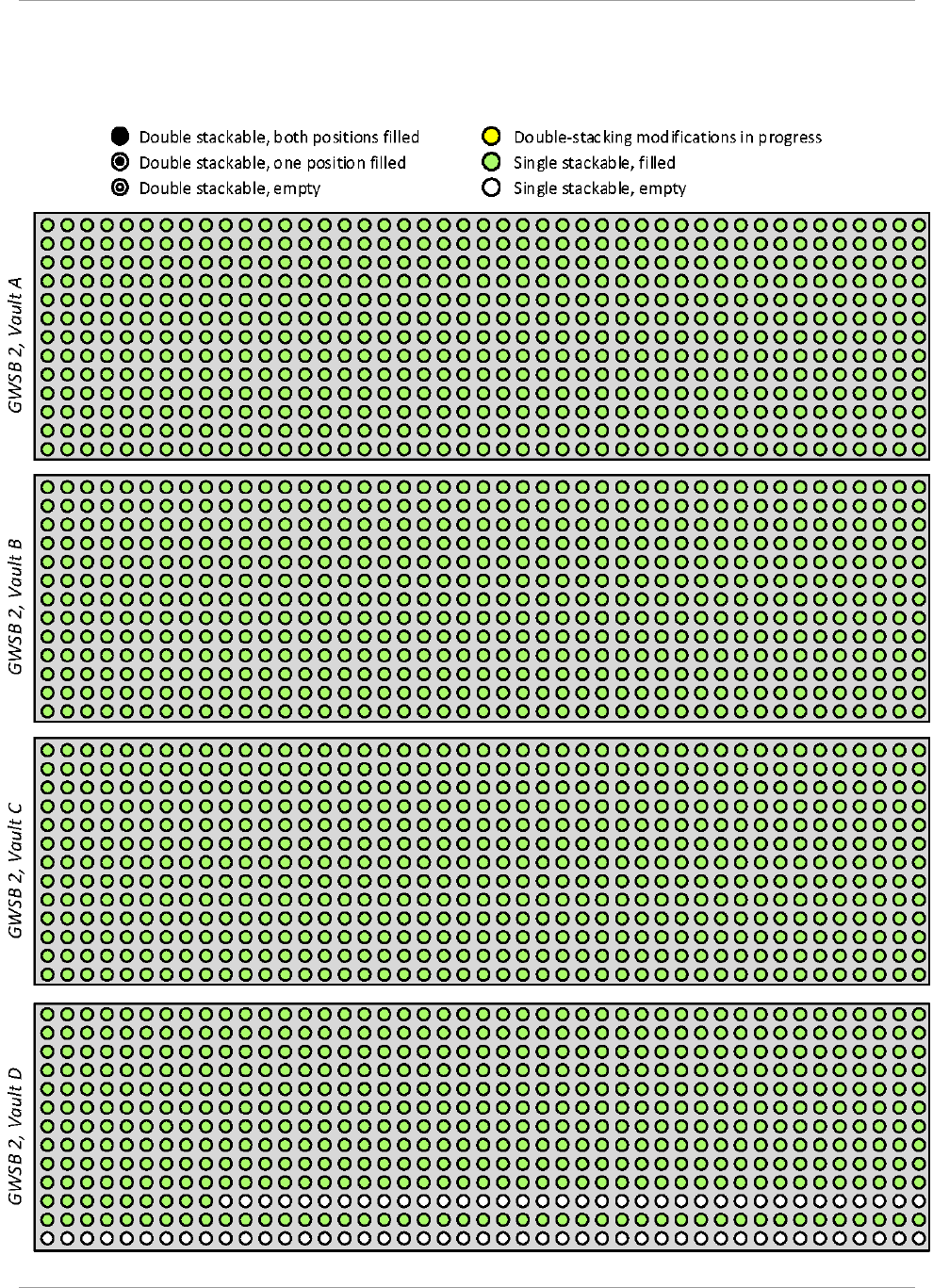
Liquid Waste System Plan SRR-LWP-2009-00001
Revision 21 January 2019
Page 47 Appendices
GWSB utilization presents the current conditions, as of December 31, 2018, of the two GWSBs showing which canister
storage positions have been converted to double-stack capability and which storage positions are empty, have a single
canister, or have two canisters.

SRR-LWP-2009-00001 Liquid Waste System Plan
January 2019 Revision 21
Appendices Page 48
Yearly Cum. Added Cum. Added Cum. Added Cum.
FY96 64 64 64 64
FY97 169 233 169 233
FY98 250 483 250 483
FY99 236 719 236 719
FY00 231 950 231 950
FY01 22
7
1,17
7
22
7
1,177
FY02 160 1,33
7
160 1,337
FY03 115 1,452 115 1,452
FY04 260 1,712 260 1,712
FY05 25
7
1,969 25
7
1,969
FY06 245 2,214 244 2,213 1 1
FY07 160 2,374 28 2,241 132 133
FY08 225 2,599 2,241 225 358
FY09 196 2,795 2,241 196 554
d
FY10 192 2,98
7
3 2,244 183 737
FY11 264 3,251 2,244 260 997
FY12 27
7
3,528 2,244 27
7
1,269
FY13 224 3,752 2,244 224 1,493
FY14 125 3,87
7
2,244 125 1,629
FY15 93 3,970 (193) 2,051 281 1,910
FY16 136 4,106 (139) 1,912 27
7
2,201
FY17 52 4,158 1,912 48 2,235
FY18 15 4,173 1,912 15 2,251
FY19 49 4,222 1,912 49 2,300
FY20 84 4,306 84 1,996 2,300
FY21 220 4,526 220 2,216 2,300
FY22 300 4,826 300 2,516 2,300
FY23 300 5,126 300 2,816 2,300
FY24 300 5,426 300 3,116 2,300
FY25 300 5,726 300 3,416 2,300
FY26 300 6,026 300 3,716 2,300
FY27 300 6,326 300 4,016 2,300
FY28 300 6,626 300 4,316 2,300
FY29 200 6,826 200 4,516 2,300
FY30 300 7,126 6 4,522 39 2,339 255 255
FY31 300 7,426 4,522 2,339 300 555
FY32 300 7,726 4,522 2,339 300 855
FY33 285 8,011 4,522 2,339 285 1,140
FY34 110 8,121 4,522 2,339 110 1,250
FY35 8,121 4,522 2,339
10
f
1,260
a
b
c
d
e
f
Note:
Dates, volumes, and chemical or radiological composition information are planning approximations only.
End of
Fiscal
Year
SRS Cans
Poured
SRS Cans in GWSB 1
(4,522 capacity)
a
SRS Cans in GWSB 2
(2,339 capacity)
b
SRS Cans in
Supplemental Storage
c
This Plan assumes supplemental canister storage is available in FY30.
GWSB 2 was built with 2,340 standard storage locations. One archived non-radioactive canister is stored in GWSB 2 yielding a
usable storage capacity of 2,339 standard canisters. GWSB 2 received its first radioactive canister in June 2006. It is expected to
reach maximum capacity in FY30. Note: its design does not accomodate stacking canisters similar to GWSB 1.
GWSB 1 filling began in May 1996. In FY15, conversion of GWSB 1 was initiated for stacking two canisters in each storage
location. When conversion is complete, canisters will be moved from GWSB 2 to GWSB 1 until it is full, retaining about 5 GWSB
№1 locations unused for contingency in case GWSB 2 is temporarily unavailable. The total capacity of GWSB 1 will be 4,524 when
conversion is complete with two positions filled with non-radioactive archive canisters.
Typically, several canisters are in the vitirification building pending transfer to canister storage. All canisters will be transferred
to canister storage before the DWPF is cleaned and flushed.
This Plan assumes that, beginning in FY20, future production canisters are placed in double stack locations within the guidance
of the double stack heat transfer calculation, M-CLC-S-00819, until GWSB 1 reaches capacity.
Remaining canisters in the vitrification buliding are moved to storage during DWPF Clean & Flush.
Numbers in italics are actuals — through
FY18. FY19 and future are forecast based on
modeling assumptions
Appendix H—Canister Storage

Liquid Waste System Plan SRR-LWP-2009-00001
Revision 21 January 2019
Page 49 Appendices
Yearly Cum.
FY19 1 1
FY20 6 7
FY21 9 16
FY22 16 32
FY23 7 39
FY24 14 53
FY25 14 67
FY26 6 73
FY27 13 86
FY28 14 100
FY29 15 115
FY30 5 120
FY31 120
FY32 1 121
FY33 1 122
FY34
FY35
End of
Fiscal
Year
TCCR Ion Exchange Columns
produced for storage in the ISS
TCCR Ion Exchange Column Assumptions
• TCCR IX column design remains the same (mass of CST is ~515 kg)
• Adsorption kinetics supports a loading of 75,000 Ci of Cs-137 per IX
column
• The capacity of CST for cesium adsorption is unaffected by salt
solution makeup or UOP manufacturing process
• Columns are filled to the 75,000 Ci Cs-137/column limit (i.e. no
partially used columns)
• Salt solution curie content and volume processed is that of System
Plan Rev. 21 Volume Balance
• Temperature of salt solution/columns is maintained constant so
CST resin kinetics/capacity is constant
• Resulting decontaminated salt solution meets the Saltstone Waste
Acceptance Criteria
Appendix I—TCCR Columns Interim Safe Storage
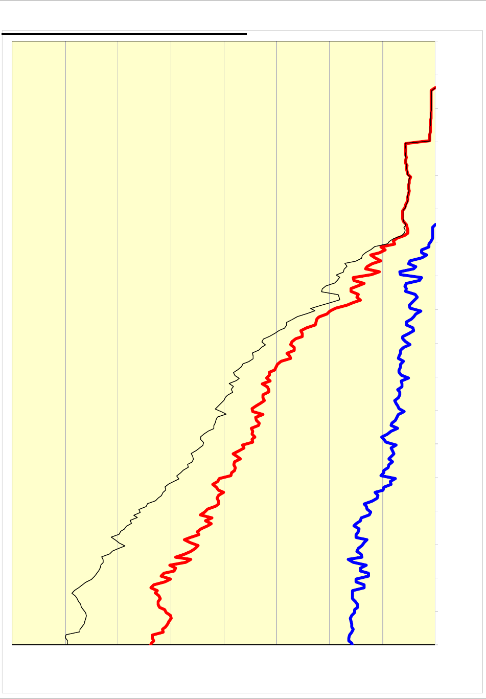
SRR-LWP-2009-00001 Liquid Waste System Plan
January 2019 Revision 21
Appendices Page 50
Remaining Type I, II,
& IV Inventory
Remaining Type III
Inventory
Total Remaining
Inventory
-
5
10
15
20
25
30
35
40
Oct-2018
Oct-2019
Oct-2020
Oct-2021
Oct-2022
Oct-2023
Oct-2024
Oct-2025
Oct-2026
Oct-2027
Oct-2028
Oct-2029
Oct-2030
Oct-2031
Oct-2032
Oct-2033
Oct-2034
Oct-2035
Oct-2036
millions of gallons
Appendix J—Remaining Tank Inventory

Liquid Waste System Plan SRR-LWP-2009-00001
Revision 21 January 2019
Page 51 Appendices
Acronyms
ARP Actinide Removal Process –process that
removes actinides and Strontium-90 (Sr-
90), both soluble and insoluble, from Tank
Farm salt solution using MST and
filtration
Ci/gal Curies per gallon
CM Closure Module
CSMP Commercial Submersible Mixing
Pumps
CSSX Caustic Side Solvent Extraction –
process for removing cesium from a
caustic (alkaline) solution. The process is a
liquid-liquid extraction process using a
crown ether. SRS plans to use this process
to remove Cesium-137 (Cs-137) from salt
wastes.
D&D Dismantlement and Decommissioning
DAR Drain, Add, Remove
DDA Deliquification, Dissolution, and
Adjustment
DF decontamination factor
DNFSB Defense Nuclear Facilities Safety Board
DOE Department of Energy
DOE-SR The DOE Savannah River Operations
Office
DQA Data Quality Assessment
DSA Documented Safety Analysis
DSS Decontaminated Salt Solution – the
decontaminated stream from any of the
salt processes – DDA, ARP/MCU, or
SWPF
DWPF Defense Waste Processing Facility – SRS
facility in which LW is vitrified (turned
into glass)
EA Environmental Assessment
EIS Environmental Impact Statement
ELAWD Enhanced Low Activity Waste Disposal
EOL End-of-Life
EPA Environmental Protection Agency
ETP Effluent Treatment Project – SRS
facility for treating contaminated
wastewaters from F & H Areas
eWAC Electronic Waste Acceptance Criteria
FFA Federal Facility Agreement – tri-party
agreement between DOE, SCDHEC, and
EPA concerning closure of waste sites.
The currently-approved FFA contains
commitment dates for closing specific LW
tanks
FESV Failed Equipment Storage Vault
FTF F-Tank Farm
FY Fiscal Year
GWSB Glass Waste Storage Building – SRS
facilities with a below-ground concrete
vault for storing glass-filled HLW
canisters
HLW High Level Waste
HM H Modified – t
he modified PUREX
process in H-Canyon for separation of
special nuclear materials and enriched
uranium
HTF H-Tank Farm
IAL Inter-Area Line
IPABS Integrated Planning, Accountability, &
Budgeting System
ISS Interim Safe Storage
IW inhibited water – well water to which
small quantities of sodium hydroxide and
sodium nitrite have been added to prevent
corrosion of carbon steel waste tanks
kgal thousand gallons
LTAD Low Temperature Aluminum
Dissolution
LLW Low Level Waste
LW Liquid (Radioactive) Waste – broad term
that includes the liquid wastes from the
canyons, HLW for vitrification in DWPF,
LLW for disposition at SDF, and LLW
wastes for treatment at ETP
MCi Million Curies
MCU Modular CSSX Unit – small-scale
modular unit that removes cesium from
supernate using a CSSX process similar to
SWPF
Mgal million gallons
MSB Melter Storage Box
MST monosodium titanate
NCSE Nuclear Criticality Safety Evaluations
NDAA Ronald W. Reagan National Defense
Authorization Act for Fiscal Year 2005,
Public Law 108-375
NDAA §3116 Section 3116 – Defense Site
Acceleration Completion—of the NDAA
NEPA National Environmental Policy Act
NGS Next Generation Solvent
NPDES National Pollution Discharge
Elimination Systems
NRC Nuclear Regulatory Commission
OA Oxalic Acid
OOS Out of Service
PA Performance Assessment
PEIS Programmatic Environmental Impact
Statement
PISA Potential Inadequacy in the Safety
Analysis
PUREX Plutonium Uranium Reduction
Extraction
RA Readiness Assessment
SRR-LWP-2009-00001 Liquid Waste System Plan
January 2019 Revision 21
Appendices Page 52
RCRA Resource Conservation and Recovery
Act
ROMP Risk and Opportunity Management
Plan
SAR Sample Analysis Report
SAS Steam Atomized Scrubber
SB Sludge Batch
SC Safety Class
SCDHEC South Carolina Department of Health
and Environmental Control – state
agency that regulates hazardous wastes at
SRS
SDI Salt Disposition Initiative
SDF Saltstone Disposal Facility – SRS facility
containing Saltstone Disposal Units
SDU Saltstone Disposal Units – Disposal Units
that receive wet grout from SPF, where it
cures into a solid, non-hazardous Saltstone
SE Strip Effluent
SEIS Supplemental Environmental Impact
Statement
SME Slurry Mix Evaporator
SMP Submersible Mixer Pump
SOL Solids Oxide Loading
SPF Saltstone Production Facility – SRS
facility that mixes decontaminated salt
solution and other low-level wastes with
dry materials to form a grout that is
pumped to SDF
SRNL Savannah River National Laboratory
SRNS Savannah River Nuclear Solutions
SRR Savannah River Remediation LLC
SRS Savannah River Site
SS Safety Significant
SSC Structure, System, or Component
STP Site Treatment Plan
SWPF Salt Waste Processing Facility –facility
that will remove Cs-137 from Tank Farm
salt solutions by the CSSX process and Sr-
90 and actinides by treatment with MST
and filtration
T&PRA Technical and Programmatic Risk
Assessment
TCCR Tank Closure Cesium Removal –process
that will remove Cs-137 from Tank Farm
salt solutions by the ion exchange process
WAC Waste Acceptance Criteria
WCS Waste Characterization System – system
for estimating the inventories of
radionuclides and chemicals in SRS Tank
Farm tanks using a combination of process
knowledge and samples
WD Waste Determination
wt% weight percent
WW well water

Liquid Waste System Plan SRR-LWP-2009-00001
Revision 21 January 2019
Page 53 References
References
1
Chew, D.P & Hamm, B.A., SRR-LWP-2009-00001, Liquid Waste System Plan, Revision 20, March 2016
2
Winship, G.C., Y-RAR-G-00022, PBS-SR-0014, Radioactive Liquid Tank Waste Stabilization and Disposition, Risk
and Opportunity Management Plan, Revision 12, Draft 2019
3
Ridley, J.M. to Foster, T.A, WDPD-17-04, Contract DE-AC09-09SR22505—Dispute Resolution Agreement for
Alleged Violations of Class 3 Industrial Solid Waste Landfill Permit Facility, Facility ID #025500-1603, (dated
10/31/16), United States Department of Energy Savannah River Site (DOE-SR), November 2016
4
Dickert, V.G., CBU-SPT-2004-00041, Progress in Implementation of Common Goals and Values, February 2004
5
WSRC-OS-94-42, Federal Facility Agreement for the Savannah River Site, August 1993, as amended through
November 2017
6
SRNS-TR-2008-00101, Savannah River Site Approved Site Treatment Plan, 2011 Annual Update, Revision 4,
November 2016
7
Bodman, S.W., DOE-WD-2005-001, Section 3116 Determination for Salt Waste Disposal at the Savannah River
Site, Revision 0, January 2006
8
DOE-WD-2005-001, Basis for Section 3116 Determination for Salt Waste Disposal at the Savannah River Site,
Revision 0, January 2006
9
Chu, S, DOE-WD-2012-001, Section 3116 Determination for Closure of F-Tank Farm at the Savannah River Site,
Revision 0, March 2012
10
DOE/SRS-WD-2012-001, Basis for Section 3116 Determination for Closure of F-Tank Farm at the Savannah
River Site, Revision 0, March 2012
11
Moniz, E.J., DOE-WD-2014-001, Section 3116 Determination for Closure of H-Tank Farm at the Savannah River
Site, Revision 0, December 2014
12
DOE/SRS-WD-2014-001, Basis for Section 3116 Determination for Closure of H-Tank Farm at the Savannah
River Site, Revision 0, December 2014
13
Pavletich, J.P., SRR-CWDA-2017-00015, Consolidated General Closure Plan for F-Area and H-Area Waste Tank
Systems, Revision 1, April 2017
14
Thomas, S.A., LWO-PIT-2006-00017, Savannah River Site – Liquid Waste Disposition Processing Strategy,
Revision 0, September 2006
15
Kent M. Coleman, P.G., to Dr. David C. Moody, Savannah River Site Z-Area Saltstone Disposal Facility Permit
Facility ID No. 02550-1603 Aiken County, August 2011
16
McAllister, J.E., Jr., M-CLC-S-00819, Heat Transfer Analysis of Double Stacking of Canisters in the Glass Waste
Storage Building #1, Revision 2, December 2018
17
X-ESR-J-00001, Waste Acceptance Criteria, Revision 2, October 2014
18
Ball, J.E., SWPF-SER-001, DOE Safety Evaluation Report for the SWPF Documented Safety Analysis S-SAR-J-
00002 R0 & Technical Safety Requirements S-TSR-J-00001 R0, Revision 0, October 2018
19
S.P. Hommel, Recommended Saltstone Waste Acceptance Criteria for Implementing the FY2016 SDF SA, SRR-
CWDA-2017-00042, Revision 0, April 2017
20
MGR-10-037, Fissile Limits in Defense Waste Processing Facility Canisters, April 2010
21
Chew, D.P., SRR-LWP-2019-00002, 2018-12-31—December 2018 Curie and Volume Inventory Report, Revision
0, January 2019
22
Waltz, R. S., Jr., C-ESR-G-00003, SRS High Level Waste Tank Crack and Leak Information, Revision 16, June
2018

SRR-LWP-2009-00001 Liquid Waste System Plan
January 2019 Revision 21
References Page 54
23
Brooke, J. N., Peters, J. F., and K. Stahell, WSRC-TR-99-00358, Hydrological Methods Can Separate Cesium
from Nuclear Waste Saltcake, 1999.
24
Mansfield, J.E. to Chu, S., January 2010

SRR-LWP-2009-00001 Liquid Waste System Plan
January 2019 Revision 21
Distribution
DOE-SR
J. L. Folk, Jr., 704-S (40)
SRR-Sr. Staff
T. A. Foster, 766-H
L. T. Ling, 766-H
M. A. Schmitz, 766-H
SRR-Staff
P. M. Allen, 766-H (7)
R. W. Blackmon, 766-H (5)
M. N. Borders, 704-56H (10)
P. J. Breidenbach, 766-H (10)
P. D. Campbell, 766-H (5)
T. F. England, 705-1C (10)
S. P. Fairchild, 766-H (10)
J. R. Freeman-Pollard, 704-56H (10)
K. A. Hauer, 766-H (7)
G. J. Matis, 704-S (10)
B. W. Witt, 704-45H (7)
SRNS
W. C. Clark, Jr, 703-H (5)
S. L. Marra, 773-A
DNFSB
D. J. Cleaves, DNFSB
Z. C. McCabe, 703-41A
M. T. Sautman, 703-41A
File
ECATS (DOE), 730-1B
D. P. Chew (300), 766-H
Records Administration, 773-52A
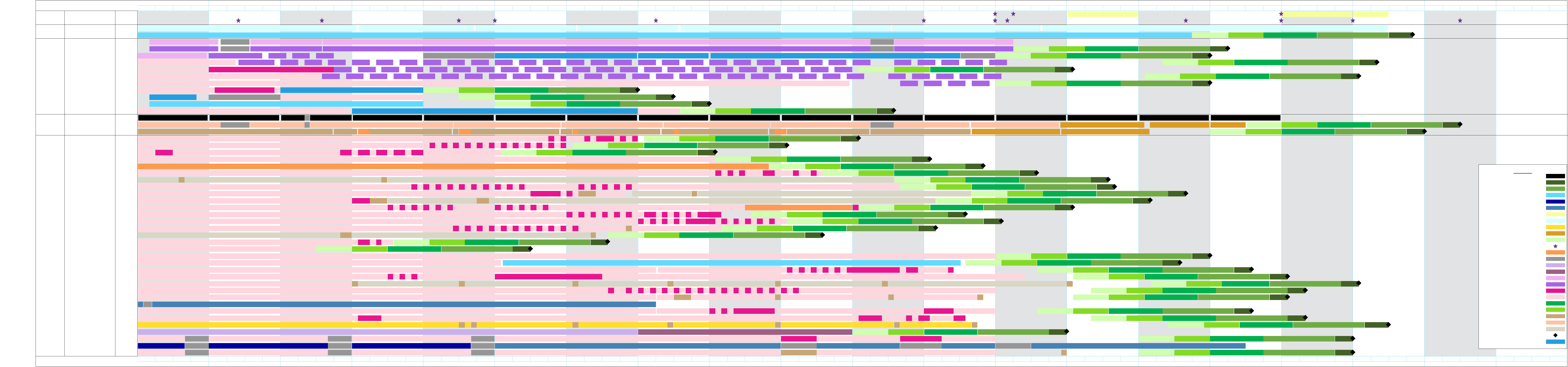
Curtain Text1
H Tank Farm - East - 2H
H Tank Farm - East - 2H
H Tank Farm - East - 2H
H Tank Farm - East
H Tank Farm - East
H Tank Farm - West - 3H
H Tank Farm - West - 3H
H Tank Farm - West - 3H
H Tank Farm - West - 3H
H Tank Farm - West
H Tank Farm - West
H Tank Farm - West
H Tank Farm - West
H Tank Farm - West
H Tank Farm - West
H Tank Farm - West
H Tank Farm - West
H Tank Farm - West
F Tank Farm
F Tank Farm
F Tank Farm
F Tank Farm
F Tank Farm
F Tank Farm
F Tank Farm
F Tank Farm
F Tank Farm
F Tank Farm
F Tank Farm
F Tank Farm
F Tank Farm
F Tank Farm
Prep
Feed
DWPF Vit
TCCR-2
TCCR-1
TCCR-1
TCCR-1
Blend
Blend
Blend
Blend
Blend
Feed
MCU/SWPF
Feed
SDF
Events
Facility Clean & Flush
Tank 43
2H Evap
Tank 38
Tank 48
Tank 39
Tank 37
Tank 30
3H Evap
Tank 32
Tank 36
Tank 35
Tank 31
Tank 29
Tank 23
Tank 22
Tank 15
Tank 14
Tank 13
Tank 47
Tank 46
Tank 45
Tank 44
Tank 34
Tank 33
Tank 28
Tank 26
Tank 25
Tank 8
Tank 7
Tank 3
Tank 2
Tank 1
Tank 51
Tank 40
Canisters
Tank 4
Tank 11
Tank 10
Tank 9
Tank 24
Tank 42
Tank 27
Tank 41
Tank 21
Tank 49
MCU/SWPF
Tank 50
SDUs
Waste Storage
Sludge Processing
Salt Processing
SPF
Key Events
FY 19 FY 20 FY 21 FY 22 FY 23 FY 24 FY 25 FY 26 FY 27 FY 28 FY 29 FY 30 FY 31 FY 32 FY 33 FY 34 FY 35 FY 36 FY 37 FY 38
Q1 Q2 Q3 Q4 Q1 Q2 Q3 Q4 Q1 Q2 Q3 Q4 Q1 Q2 Q3 Q4 Q1 Q2 Q3 Q4 Q1 Q2 Q3 Q4 Q1 Q2 Q3 Q4 Q1 Q2 Q3 Q4 Q1 Q2 Q3 Q4 Q1 Q2 Q3 Q4 Q1 Q2 Q3 Q4 Q1 Q2 Q3 Q4 Q1 Q2 Q3 Q4 Q1 Q2 Q3 Q4 Q1 Q2 Q3 Q4 Q1 Q2 Q3 Q4 Q1 Q2 Q3 Q4 Q1 Q2 Q3 Q4 Q1 Q2 Q3 Q4 Q1 Q2 Q3 Q4
Tk 22: DWPF Recycle Receipt and Storage
Tk 47 Salt Solution Hold Tank
Tk 9 Salt Solution Storage Tk 9 Feeds TCCR-1
Tk 11: TCCR-1 Receipt Tk
Tk 23: Salt Solution Hold Tank
Tk 30: 3H Evaporator Concentrate Receipt Tank
Tk 32: 3H Evaporator Feed Tank
Tk 3: Salt Solution Hold Tank
Tk 35: Sludge Hub Tank & Salt Solution Hold Tank
Tk 3 Salt Solution Hold Tank
Tk 38: 2H Evap Conc Recpt Tk
Tk 39: H Canyon Waste Receipt
Tk 43: 2H Evap Feed Tank
Tk 13 HR
Tk 14: Salt Solution Hold Tank
Tk 13 Sampling Tk 13 Sample Analysis Tk 13 Closure Documentation
Tk 14 HR Tk 14 Sampling Tk 14 Sample Analysis Tk 14 Closure Documentation
Blend SWPF B2
Tk 15: Sludge Storage Tank
Tk 22: Collect and Redistribute Spent Wash Water
B4
Tk 23: Decontaminated Salt Soln Hold Tank (TCCR Support)
Tk 24 Sampling Tk 24 Sample Analysis Tk 24 Closure Documentation
Tk 38 Salt Dissolution
B6
Tk 32 Salt Soln Hold Tk Tk 32 SSHT Tk 32 Salt Soln Hold Tk
Tk 30 SSHT
B9
Tk 30 SSHT Tk 30 SSHT
B12 B15
Tk 36 SSHT
B18
1312
Tk 4 HR Tk 4 Sampling
Tk 4 Sample Analysis and Report
Tk 4 Closure Docs
Tk 10 Supports TCCR-1 Tk 10 HR Tk 10 Sampling Tk 10 Sample Analysis Tk 10 Closure DocumentationTk 10 Feeds TCCR-1
Tk 42 HR Tk 42 Sampling Tk 42 Sample Analysis Tk 42 Closure Documentation
Tk 48 Treatment Tk 48 Sampling Tk 48 Sample Analysis Tk 48 Closure Documentation
Tk 15 HR
Tk 49 HR Tk 49 Sampling
Tk 49 Sample Analysis and Report
Tk 49 Closure Docs
SB10 Prep SB11 Prep SB11 Prep SB12 Prep SB13 Prep SB14 Prep SB15 Prep
Tk 34 Sludge Hub Tank Tk 34 Sludge Hub Tank
2H Evap Ops (DWPF Recycle)
2H Outage 2H Evap Ops (DWPF Recycle) 2H Outage 2H Evap Ops (DWPF Recycle) 2H Outage 2H Evap Ops (General Use) 2H Evap Outage 2H Evap Ops (General Use)
B51 B54 B57 B60 B63 B66 B69 B72 B75 B77 B80 B83 B86 B89 Tk 41 HR
Tk 37: 3H Evaporator Concentrate Receipt Tk
Tk 41 Sampling
Tk 41 Sample Analysis & Report
Tk 41 Closure Docs
B13 B16 B19 B22 B25 B28 B31 B34 B55 B58 B61 B64 B67 B70 B73 Tk 27 HR Tk 27 Sampling
2H Outage
Tk 27 Sample Analysis Tk 27 Closure Documentation
Tk 38: 2H Evap Conc Recpt Tk 2H Outage Tk 38: 2H Evap Conc Recpt Tk
2H Outage Tk 43: 2H Evaporator Feed Tank 2H Outage Tk 43: 2H Evaporator Feed Tank
Tk 25: Salt Solution Hub Tank
SWPF Throughput @ 9 Mgal/yrSWPF Throughput @ 6 Mgal/yr
Tk 49 Feeds SWPF @ 6 Mgal/yr
Tk 48 HR
DWPF Clean & Flush
Tk 50 HR
84 canisters49 canisters
3H Evap Ops
B29 B32 B35 B38 B41 B44B8 B11 B14 B17 B20 B23 B26 B71 B74 B76 B79 B82 B85 B88B47 B50 B53 B56 B59 B62 B65 B68
Tk 44 LTAD Receipt Tank
Filling SDU-7
Melter Outage
Tk 49 Feeds SWPF @ 9 Mgal/yr
Melter Outage
SWPF Throughput 9 Mgal/yr
Tie-Ins & Hot Comm
Tk 21 Feeds TCCR-1 Tk 21 Feeds TCCR-1 and TCCR-2
Filling SDU-8
Tk 21 HR Tk 21 Sampling Tk 21 Sample Analysis Tk 21 Closure Documentation
Melter Outage
SWPF Clean & Flush
Move TCCR-1 Unit TCCR-1 Ops & TCCR-2 Moves
Tk 33 Sludge Hub Tk
Tk 33 Sludge Hub Tk
Tk 24: Dissolved Salt Solution Hub Tk B78 B81 B84 B87
Tk 31: Salt Solution Hub Tank Tk 31 Salt Dissolution Tk 31: Salt Solution Hub Tank
Tk 4 Feeds TCCR-2 @ 1 Mgal/yr
Tk 29: Salt Solution Hold Tank
Tk 50 Closure DocumentationTk 50 Sampling Tk 50 Sample Analysis
Tk 41: Salt Solution Hold Tank
Tank 42: Salt Solution Hold Tank
Tk 4: Salt Solution Hold Tank
Tk 48: Precipitate Storage
TCCR Mods If Needed
Tk 27: Salt Dissolution
Tk 9 Salt Dissolution
Tie-Ins & Hot Comm
SB9 to DWPF
Tie-Ins & Hot Comm
Tk 38 Salt Dissolution
Tk 38: 2H Evap Conc Recpt Tk (Gen Use)
220 canisters
Tk 43 Sludge Removal
Tk 43: 2H Evaporator Feed Tank
2H Evap Ops (General Use)2H Evap Outage TCCR Supports Heel Removals
Move TCCR
… Move TCCR
B33 B36 B39 B42 B45 B48
B40 B43 B46 B49 B52
300 canisters 300 canisters
SB12 to DWPF SB13 to DWPF
300 canisters 300 canisters 300 canisters 300 canisters 300 canisters 200 canisters 300 canisters 300 canisters 300 canisters
Tk 49 Feeds MCU
285 canisters 110 canisters
SB16 Prep
Tk 49 Feeds SWPF @ 9 Mgal/yr
Heel Batch 1 Prep Heel Batch 2 Prep Tk 51 HR Tk 51 Sampling Tk 51 Sample Analysis Tk 51 Closure Documentation
SB14 to DWPF SB15 to DWPF SB16 to DWPF Heel Batch 1 to DWPF Heel Batch 2 to DWPF
Heel Batch 3 to DWPF
Tk 40 HR Tk 40 Sampling Tk 40 Sample Analysis Tk 40 Closure Documentation
Tk 1: Salt Solution Hold Tank
Tk 2: Salt Solution Hold Tank
Tk 28: Salt Solution Hold Tank
Tk 21: MCU Support
Tk 1 HR Tk 1 Sampling Tk 1 Sample Analysis Tk 1 Closure Documentation
Tk 2 HR Tk 2 Sampling Tk 2 Sample Analysis Tk 2 Closure Documentation
Tk 3 HR Tk 3 Sampling Tk 3 Sample Analysis Tk 3 Closure Documentation
Filling SDU-6
Blend SWPF B1
Tk 7 HR Tk 7 Sampling Tk 7 Sample Analysis Tk 7 Closure Documentation
B3
Tk 8 HR Tk 8 Sampling Tk 8 Sample Analysis Tk 8 Closure Documentation
B5
Tk 25 HR Tk 25 Sampling Tk 25 Sample Analysis Tk 25 Closure Documentation
B7
Tk 28 HR Tk 28 Sampling Tk 28 Sample Analysis Tk 28 Closure Documentation
Tk 34 HR Tk 34 Sampling Tk 34 Sample Analysis Tk 34 Closure DocumentationTk 34: Salt Solution Hold Tank
Tk 44: Salt Solution Hold Tank Tk 44 Salt Solution Hold Tank Tk 44 HR Tk 44 Sampling Tk 44 Sampling Analysis Tk 44 Closure Documentation
Tk 45: Salt Soln Hold Tk Tk 45 HR Tk 45 Sampling Tk 45 Sampling Analysis Tk 45 Closure Documentation
Tk 47 Closure Documentation
Tk 46: Salt Solution Hold Tank Tk 46 Sampling Tk 46 Sampling Analysis Tk 46 Closure Documentation
Tk 47 HR Tk 47 Sampling Tk 47 Sampling Analysis
Tk 9 HR Tk 9 Sampling Tk 9 Sampling Analysis Tk 9 Closure Documentation
B37
Tk 11 HR Tk 11 Sampling Tk 11 Sampling Analysis Tk 11 Closure Documentation
Tk 22 Closure Documentation
B21
Tk 22 HR Tk 22 Sampling Tk 22 Sample Analysis
Tk 23 HR Tk 23 Sampling Tk 23 Sample Analysis Tk 23 Closure Documentation
B24
Tk 30 Salt Dissolution Tk 30 HR
B27
Tk 35: Sludge Hub Tank & Salt Solution Hold Tank
Tk 30 Sampling Tk 30 Sample Analysis Tk 30 Closure Documentation
11
B30
Tk 31: Salt Solution Hub Tank Tk 31 HR Tk 31 Sampling Tk 31 Sample Analysis Tk 31 Closure Documentation
Tk 27: Salt Solution Hold Tank
Tk 32 HR Tk 32 Sampling Tk 32 Sample Analysis
B10
Tk 32 Closure Documentation
Tk 35: Sludge Hub Tank & Salt Solution Hold Tank
Tk 33: Salt Solution Hold Tank Tk 33 HR Tk 33 Sampling Tk 33 Sample Analysis Tk 33 Closure Documentation
Tk 35: Sludge Hub Tank & Salt Solution Hold Tank
Tk 35 Closure DocumentationTk 35 HR Tk 35 Sampling Tk 35 Sample Analysis
Tk 37: 3H Evaporator Concentrate Receipt Tk Tk 37 HR Tk 37 Sampling Tk 37 Sample Analysis Tk 37 Closure Documentation
2H Outage Tk 38 Closure DocumentationTk 38 HR
Tanks 50 Feeds SPF
Tk 38 Sampling Tk 38 Sample Analysis
Tk 39: H Canyon Waste Receipt Tk 39: H Canyon Waste Receipt Tk 39 HR Tk 39 Sampling Tk 39 Sample Analysis Tk 39 Closure Documentation
Tk 43: 2H Evaporator Feed Tank
Filling SDU-9 Filling SDU-10 Filling SDU-11 Filling SDU-12 Filling SDU-13
Tk 43 HR Tk 43 Sampling Tk 43 Sample Analysis Tk 43 Closure Documentation
Tk 13: Consolidate Heels from Tks 9, 10, 11, 14
2H Outage
SB9 to DWPF SB10 to DWPF
SPF Clean & Flush
Tk 24: Evaporator Concentrate Hold Tank Tk 24 HR
SB11 to DWPF
Tk 29: 3H Evaporator Support Tank Tk 29 Sample Analysis Tk 29 Closure Documentation
Tk 4: SSHT
Tk 38: 2H Evaporator Concentrate Receipt Tank (General Use)
Tk 39: H Canyon Waste Receipt Tk 39: H Canyon Waste Receipt Tk 39: H Canyon Waste Receipt
HB1
14 Tk 35: Sludge Hub Tank & Salt Solution Hold Tank 15 Tk 35: Sludge Hub Tank & Salt Solution Hold Tank 16 Tk 35: Sludge Heel Removal Hub Tank
HB2
Tk 29 HR Tk 29 SamplingTk 29 Salt Dissolution
Tk 26: Sludge Tank Tk 26: Sludge Storage Tank Tk 26 HR Tk 26 Sampling Tk 26 Sample Analysis
Tk 7: Interstitial Liquid and Supernate Hub Tank
Tk 26 Closure DocumentationTk 26 Sludge Storage Tank
Tk 8: LTAD Receipt Tank
Tk 28 SSHT
Tk 13: Sludge Hub Tank
Tk 28 Salt Solution Hold Tank
Tk 33 Consolidation of FTF Type III Heels
Tk 36 Salt Solution Hub Tank Tk 36 HR Tk 36 Sampling Tk 36 Sample Analysis Tk 36 Closure Documentation
MCU Operations
Tk 44 SSHT
Tk 15 Sampling Tk 15 Sample Analysis Tk 15 Closure Documentation
Tk 46 HR
Tk 47 Salt Solution Hold Tank
Tk 47: Salt Solution Hold Tank
F TF Cleanout CompleteSWPF Hot Commissioning
Tk 13 Closed
Tk 14 Closed
Tk 4 Closed
Tk 10 Closed
Tk 42 Closed
Tk 50 Closed
Tk 48 Closed
Tk 49 Closed
Glass Waste Storage Project Required
2H Evap Shut Down
Tk 41 Closed
Tk 27 Closed
SWPF Shut Down
3H Evap Shut Down
Tk 51 Closed
Tk 21 Closed
2H Converted to General Purpose Service F TF Closed LW Program CompleteH TF Cleanout Complete
DWPF Shut Down
SPF Shut Down
Tk 40 Closed
Tk 2 Closed
Tk 3 Closed
Tk 7 Closed
Tk 8 Closed
Tk 25 Closed
Tk 28 Closed
Tk 34 Closed
Tk 44 Closed
Tk 45 Closed
Tk 47 Closed
Tk 46 Closed
Tk 9 Closed
Tk 11 Closed
ELAWD II required
Tk 22 Closed
Tk 23 Closed
Tk 30 Closed
Tk 31 Closed
Tk 32 Closed
Tk 33 Closed
Tk 35 Closed
Tk 37 Closed
Tk 38 Closed
H Canyon Receipts Cease
Tk 39 Closed
Tk 43 Closed
Tk 24 Closed
Tk 29 Closed
DWPF Recycle Diverted
Tk 1 Closed
Tk 26 Closed
Tk 36 Closed
Tk 15 Closed
Legend
Canisters
Closure (Grout)
Closure Documentation
Decontaminated Salt Solution
Evaporator Operations (DWPF Recycle)
Evaporator Operations (General Use)
Facility Clean and Flush
Filling SDU
H Canyon Waste Receipts
Heel Batch
Heel Removal
Key Event
LTAD
Outage
Precipitate Storage
Precipitate Treatment
Salt Batch Processing
Salt Batches
Salt Dissolution
Salt Tank
Sample Analysis
Sampling
Sludge Batch
Sludge Processing
Sludge Tank
Tank Closed
TCCR Feed
2019-02-04, 13:26
SRR-LWP-2009-00001
January 2019
Liquid Waste System Plan
Revision 21
Appendix E—LW System Plan—Rev 21 Summary
DV
