REQUIREMENTS FOR
ELECTRIC SERVICE
CONNECTION
2024 Edition

i
Requirements for Electric
Service Connection
Welcome to the 2024 edition of the Seattle City Light Requirements for Electric Service
Connection (RESC). This handbook is designed for use by City Light customers,
contractors, and electricians to explain utility requirements for a variety of electric service
installations.
The RESC serves as a guide to the process of obtaining new electric service. The
information presented herein is not intended to be all-inclusive; customers are required
to review and adhere to the requirements of all standards referenced in this document
relevant to their project.
A companion document, the Standards for Electric Service, is a collection of all the
standards referenced in the RESC and in Service Construction Letter attachments.
R. Craig Smith, Chief Customer Officer

ii
Seattle City Light
Requirements for Electric Service Connection 2024 Edition
Published by the Seattle City Light Standards Engineering Organization
Seattle, Washington
January 2024
Contact: Standards.Pub@seattle.gov
Prepared by Laura Vanderpool, Standards Engineering
Cover photo credit: Muneer Shetab
iii
Table of Contents
Preface: Significant Changes Since Last Publication ......................................................................... vi
1.
Getting Started: Applying for Electric Service .......................................................................... 1
1.1. Introduction ....................................................................................................................................................... 1
1.3. Connection Timeline ...................................................................................................................................... 1
1.4. Service Connection ......................................................................................................................................... 2
1.5. Charges ............................................................................................................................................................... 2
1.6. Application Process for New or Enlarged Services ............................................................................ 3
1.6.1. Pre-Application Consultation ..................................................................................................... 3
1.6.2. Application for Electric Service .................................................................................................. 3
1.7. Permitting and Inspections ......................................................................................................................... 4
1.8. Easements .......................................................................................................................................................... 4
1.9. Location of, and Excavation Near, Underground Utilities ............................................................... 4
1.10. Clearance Between 26 kV Overhead Distribution Conductors and Buildings ......................... 5
1.11. Notification of Added Load......................................................................................................................... 5
1.12. Balanced Load .................................................................................................................................................. 5
1.13. Voltage Surge Protection ............................................................................................................................. 5
1.14. Electromagnetic Interference ..................................................................................................................... 5
1.15. Available Fault Current .................................................................................................................................. 6
1.16. Online Resources ............................................................................................................................................. 6
1.17. Installation of Facilities for Other Utilities ............................................................................................. 6
2. Temporary Services ..................................................................................................................... 7
2.1. Introduction ....................................................................................................................................................... 7
2.2. Requirements, General .................................................................................................................................. 7
2.3. Time Limit ........................................................................................................................................................... 7
2.4. Electrical Permits and Inspections ............................................................................................................ 7
2.5. Charges ............................................................................................................................................................... 7
2.6. Engineering Requirements for Large Services ..................................................................................... 7
2.7. Temporary Overhead Service ..................................................................................................................... 7
2.8. Temporary Underground Service ............................................................................................................. 9
3. Looped Radial Service .............................................................................................................. 10
3.1. Introduction .................................................................................................................................................... 10
3.2. Availability of Service .................................................................................................................................. 10
3.3. Modifications to Existing Electric Service ........................................................................................... 11
3.4. Available Service Voltages and Maximum Secondary Service Entrance Ratings ................ 12
3.5. Clearances ....................................................................................................................................................... 13
3.6. Water Entry Prevention .............................................................................................................................. 13
3.7. Secondary Service ........................................................................................................................................ 13
3.7.1. Secondary Overhead Services ................................................................................................ 14
3.7.2. Secondary Underground Services ......................................................................................... 19
iv
3.8.
Primary Service .............................................................................................................................................. 20
3.8.1. Water Entry Prevention ............................................................................................................. 21
3.8.2. Vault Access ................................................................................................................................... 21
3.9. Fire Clearance ................................................................................................................................................ 22
3.10. Vibration and Noise Levels ....................................................................................................................... 22
3.11. Elevators ........................................................................................................................................................... 22
3.12. Special Services ............................................................................................................................................. 22
3.12.1. Mobile Home Parks .................................................................................................................... 22
3.12.2. Mobile Homes on Individual Owner Lots (not part of a mobile home community) . 22
3.12.3. Houseboat Piers ........................................................................................................................... 22
3.12.4. Boat Moorages ............................................................................................................................. 23
3.12.5. Unit Lot Subdivisions ................................................................................................................. 23
4. Network Services ..................................................................................................................... 24
4.1. Introduction .................................................................................................................................................... 24
4.2. Availability of Service .................................................................................................................................. 24
4.3. Clearances Between SCL Underground Structures and Other Structures ............................. 25
4.4. Permitting and Inspections ...................................................................................................................... 25
4.5. Service Notes, General ............................................................................................................................... 25
4.6. Vault Construction ....................................................................................................................................... 26
4.7. Water Entry Prevention .............................................................................................................................. 26
4.8. Vault Access .................................................................................................................................................... 26
4.9. Fire Clearance ................................................................................................................................................ 27
4.10. Vibration and Noise Levels ....................................................................................................................... 27
4.11. Elevators ........................................................................................................................................................... 27
4.12. NEC-Sized Service Entrances in Network Areas ............................................................................... 27
4.13. Secondary Service ........................................................................................................................................ 28
4.14. Primary Service .............................................................................................................................................. 28
4.15. Fault Current Limiters ................................................................................................................................. 29
5. Distributed Energy Resources ................................................................................................. 30
5.1. Overview of the Interconnection Process ........................................................................................... 30
5.2. Utility Programs for Distributed Energy Resources ........................................................................ 33
5.3. Engineering Review ..................................................................................................................................... 33
5.4. Safety Disconnects ....................................................................................................................................... 34
5.5. Compliance with Metering Requirements .......................................................................................... 35
5.6. Line Side Taps ................................................................................................................................................ 35
5.7. Interconnection within Network Service Areas ................................................................................ 36
6. Metering ................................................................................................................................... 37
6.1. Introduction .................................................................................................................................................... 37
6.2. Requirements, General ............................................................................................................................... 37
6.2.1. Electric Utility Service Equipment Requirements Committee (EUSERC) Material and
Equipment Requirements......................................................................................................... 37
6.2.2. Service Entrance Conductors for Metered Loads ........................................................... 37
6.2.3. Conductor Connections ............................................................................................................ 38
v
6.3.
Voltages ........................................................................................................................................................... 38
6.4. Meter Sockets ................................................................................................................................................ 38
6.5. Location, Access, and Protection of Metering Equipment ........................................................... 39
6.5.1. Location ........................................................................................................................................... 39
6.5.2. Access to Metering Equipment .............................................................................................. 40
6.5.3. Physical Protection of Metering Equipment ..................................................................... 40
6.6. Meter Height, Working Space, and Clearance Requirements .................................................... 41
6.7. Service Entrance Equipment Sequencing ........................................................................................... 41
6.7.1. Single Self-Contained Meter Installation ........................................................................... 41
6.7.2. Multi-Unit Self-Contained Meter Installations ................................................................. 41
6.8. Metering Requirements for Multi-Unit Buildings ............................................................................ 41
6.9. Current Transformers .................................................................................................................................. 43
6.9.1. Current Transformer-Rated Metering ................................................................................. 43
6.9.2. Landing Pads and Enclosures ................................................................................................. 43
6.9.3. Secondary Wiring ........................................................................................................................ 45
6.10. Switchgear ....................................................................................................................................................... 45
6.10.1. General ............................................................................................................................................. 45
6.10.2. Switchgear Operating at Voltages Up to and Including 480 V ................................. 46
6.10.3. Switchgear Operating at Voltages Greater Than 480 V ............................................... 46
6.11. Master Metering ........................................................................................................................................... 46
6.12. Advanced Metering Infrastructure (AMI) for Meter Rooms ........................................................ 46
6.13. Communications Provisions for Large Metered Loads ................................................................. 47
6.15. Net Metering .................................................................................................................................................. 48
7. Motors and Special Loads ....................................................................................................... 49
7.1. Introduction .................................................................................................................................................... 49
7.2. Motor-Starting Limits and Interference .............................................................................................. 49
7.3. Voltage Flicker ............................................................................................................................................... 49
7.4. Starting Limitations on Single-Phase Motors ................................................................................... 50
7.5. Starting Limitations on Polyphase Motors for Secondary Services.......................................... 50
7.6. Electric Power Regeneration Due to Motor Drive/Control .......................................................... 50
7.7. Maximum Switched Load .......................................................................................................................... 51
7.8. Welding Equipment ..................................................................................................................................... 51
7.9. Minimum Power-Factor Limitations ..................................................................................................... 51
7.9.1. Lighting ............................................................................................................................................ 51
7.9.2. 85% Minimum Power Factor ................................................................................................... 51
7.9.3. Capacitor Control ........................................................................................................................ 51
8. Emergency Backup: Generators and Energy Storage Systems ............................................. 52
8.1. Introduction .................................................................................................................................................... 52
8.2. Inverter-Based Emergency Backup Systems ...................................................................................... 52
8.3. Transfer Switches .......................................................................................................................................... 52
9. Maintenance of Equipment and Facilities .............................................................................. 53
9.1. Introduction .................................................................................................................................................... 53
9.2. Charges ............................................................................................................................................................ 54
9.3. Temporary Restoration of Service ......................................................................................................... 54
Glossary ............................................................................................................................................... 55
Appendix: Multi-Unit Metering Pre-Job Checklist .......................................................................... 62

vi
Significant Changes Since Last Publication
2023
Edition
Section
2024
Edition
Section
Title
Description
1
1
Getting Started: Applying
for Electric Service
1.3
1.3
Connection Timeline
Added a list of projects that “often need engineering
services.”
Deleted Note 1 below Table 1.3.
Relocated Note 2 to body text preceding the table.
1.10
1.10
Clearance Between 26 kV
Overhead Distribution
Conductors and Buildings
In boxed-out paragraph at the end of the section,
construction standard title revised to add “radial” in front of
“clearance.”
3
3
Looped Radial Service
3.3
3.3
Modifications to Electric
Service
“Modifications” changed to “Certain elective modifications.”
Bullet list modified for clarity; “change of panel location”
changed to “change of meter location, “any increase to the
load capacity…” changed to “any increase to the capacity of
the service.“ New bullets added: “Legal dwelling units.”
3.5
3.5
Clearances
In first paragraph, SCL D2-3 citation replaced with 0100.02,
0100.03, and 0100.05 (new standards created to replace this
old standard).
Boxed-out paragraph at the end of the section revised to
replace the D2-3 citation with the new standard numbers
and titles.
3.12.5
3.12.5
Unit Lot Subdivisions
Two paragraphs added to clarify requirements and to add
Seattle Municipal Code section 23.24.045 (F) as part of that
clarification.
5
5
Distributed Energy
Resources
Entire chapter rewritten to better capture existing processes
for interconnection with City Light and to better clarify
requirements for DERs. Of particular note is a new
requirement for inverters (see Section 5.3).
6
6
Metering
6.2.2
6.2.2
Service Entrance
Conductors for Metered
Loads
Changed order of paragraphs for clarity.
Paragraph that begins with “Unmetered service conductors
must not pass through any junction box…” changed to “For
single-meter installations, metered service conductors must
not pass through any junction box…”
6.3
6.3
Voltages
In Exception statement, added the word “residential” before
the phrase “distribution in multi-unit buildings”
6.4
6.4
Meter Sockets
Added the paragraph statement, “Line side taps are not
allowed in meter sockets.”

vii
6.7.2
6.7.2
Multi-Unit Self-
Contained Meter
Installations
In first bullet, the phrase “…more than six individual
sockets…” changed to “…two or more individual sockets…”
to coordinate with new electrical code requirements.
6.8
6.8
Multi-Unit Services
Title of section changed from “Multi-Unit Buildings” to
“Multi-Unit Services.”
Paragraph that began with “The number of meter centers in
apartment buildings…” removed as the statement is no
longer valid.
Paragraphs re-ordered with small text changes.
Paragraph that begins with “Prior to meter installation, all
meter sockets…” changed to
“Prior to meter installation, all
meter sockets must be identified with permanent labeling
by final space or unit number, letter designation, and/or
street address. Meter sockets must have engraved phenolic
nameplates affixed to the socket covers. Nameplates must
be placed directly beneath the meter socket on the side
closest to the disconnect switch. See Figure 6.8.
Figure 6.8, Phenolic Nameplate Placement, added.
Paragraph that began with “All multi-unit buildings must
have at least one meter for each unit” changed to “All multi-
use services must have at least one meter for each legal
dwelling unit.”
6.9.2
6.9.2
(Current Transformers)
Landing Pads and
Enclosures
Added to the end of the first paragraph, “Line-side taps are
not allowed.”
8
8
Emergency Backup:
Generators and Energy
Storage Systems
Chapter title changed from “Emergency Backup Generators.”
n/a
8.1
Introduction
Content added to distinguish emergency backup application
of generators and energy storage systems from such
systems used as DERs.
8.3
8.3
Disconnect Switches
Content revised to eliminate requirement for disconnect
switches for emergency backup generators and energy
storage systems.
Glossary
The following definitions added:
Accessory Dwelling Unit (ADU)
Interconnection Facility
Inverter-Based Resource
Machine-Based Generation Resource
Microgrid
Nameplate Capacity (DER-specific)
Operate in Parallel
System Upgrades (DER-specific)

CITY LIGHT REQUIREMENTS FOR ELECTRIC SERVICE CONNECTION 2024 EDITION | PAGE 1
1. Getting Started: Applying for Electric Service
1.1. Introduction
This chapter outlines the process for applying for service and securing all permits and inspections, as well
as provides a timeline of average turnaround times to complete the application process.
The Standards for Electric Service, an annual publication consisting of construction and material standards
related to electric service, can be found HERE
.
For questions or comments concerning the RESC, please contact Standards.Pub@seattle.gov.
1.2. Service Areas
Customers will be assigned a City Light Representative based on the location and complexity of the
project. Visit the Apply for New or Upgraded Electric Service
page and click on the link (projects up to 1
MW or projects over 1 MW) to determine your correct City Light contact for your project.
City Light has two categories of distribution: Looped Radial and Network. Network areas include
Downtown Seattle, South Lake Union, First Hill, and parts of the University District. Requirements related
to the Looped Radial system are discussed in Chapter 3, and requirements related to our Network areas
are discussed in Chapter 4.
1.3. Connection Timeline
Table 1.3 shows estimated times required for each phase of the application process.
Projects requiring special transformation or line extensions depend in part on equipment availability.
It is essential that contractors notify City Light well in advance of designing their buildings, as the
requirements for a primary service may alter the building design. For instance, City Light may require
space not only for the vault, but for a primary switchgear room as well.
Projects that often require engineering services include, but are not limited to:
• 120/240 volts, single-phase services above 200 amperes
• Services feeding more than one building, residential lot, or unit-lot
• Three-phase services
• Underground services
• Services inside the Network service area
• Services adding or including Distributed Energy Resources (DERs)
• No existing distribution on street and/or the proposed service pole is in an alley
CITY LIGHT REQUIREMENTS FOR ELECTRIC SERVICE CONNECTION 2024 EDITION | PAGE 2
TABLE 1.3. ESTIMATED TURNAROUND TIMES PER PHASE OF APPLICATION PROCESS,
LOOPED RADIAL
Service Type
Application
Processing
Engineering
Service
Connections
Service removal – simple (single-phase, 400 A or less)
2 weeks
Not applicable
6 weeks
Service removal – complex (three-phase and/or underground)
2 weeks
8 weeks
8 weeks
Temporary power – simple (single-phase, overhead, 400 A or less)
2 weeks
Not applicable
6 weeks
Temporary power – complex (three-phase and/or underground)
2 weeks
8 weeks
8 weeks
Service upgrade – simple (single-phase, overhead, 200 A or less)
2 weeks
10 weeks
10 weeks
Service upgrade – complex (three-phase and/or underground)
2 weeks
8 weeks
10 weeks
New service – simple (single-phase, overhead, 400 A or less)
2 weeks
10 weeks
10 weeks
New service – complex (three-phase and/or underground)
2 weeks
12 weeks
16 weeks*
Line extensions, plat development
2 weeks
16 weeks
16 weeks*
* Add up to five weeks for non-arterial street permitting, and fifteen weeks for arterial permitting.
1.4. Service Connection
City Light will make service connections only when:
• All applicable City Light requirements have been met.
• The customer’s responsibilities, as delineated herein, in a Service Construction Letter,
in a contract, or via an in-field conversation with a City Light Representative have
been fulfilled.
• All City Light inspections have been completed and the project approved.
1.5. Charges
City Light will determine charges for service work based on the size of the service, the service location,
and the work required to connect it to our system. Charges must be paid prior to the work being done,
either at an SCL Payment Counter or by mail. Field representatives are not allowed to accept payments.
See City Light Departmental Policy and Procedure (DPP) 417, Service Installation
for service installation
charges. Click on “Accounts and Charges” and scroll down list to locate.

CITY LIGHT REQUIREMENTS FOR ELECTRIC SERVICE CONNECTION 2024 EDITION | PAGE 3
1.6. Application Process for New or Enlarged Services
1.6.1. Pre-Application Consultation
City Light provides general engineering and service advice prior to application to determine project
feasibility and considerations.
Customers are strongly advised to contact City Light during the planning phase of their project to verify
the available service point and requirements in order to avoid costly mistakes and service delays.
Contact information:
Small/Medium Projects
(206) 233-APPS (2777)
Email: SCL_serviceapplications@seattle.gov
Large Commercial and Industrial Projects
(1 MW demand and greater)
Seattle Municipal Tower
700 5
th
Avenue
(206) 684-3186
Email: SCL_serviceapplication[email protected]
1.6.2. Application for Electric Service
Customers can apply for electric service using the online Application for Electric Service
.
Based on the application’s criteria, customers will need to submit a plan package for City Light review and
comment.
A typical plan package, provided for both permanent and temporary construction, consists of the
following elements:
• Legal Site Plan
• Electrical Site Plan
• Building Elevation Plan
• Riser Diagram
• Load Calculations
Additional documents, such as easements, in-building vault details, street improvement plans, and short
plat/unit lot subdivision information may be required to complete the project. The City Light
Representative assigned to your project will advise customers of any additional documents required.

CITY LIGHT REQUIREMENTS FOR ELECTRIC SERVICE CONNECTION 2024 EDITION | PAGE 4
1.7. Permitting and Inspections
For projects located in the public right-of-way in incorporated King County, which includes Burien,
Lake Forest Park, Normandy Park Renton, SeaTac, Seattle, Shoreline, and Tukwila, customers can do all
civil construction work. The customer is responsible for securing all required permits and inspections.
For projects located in the public right-of-way in unincorporated King County, which includes
Skyway and White Center, City Light is required to do all civil construction work. City Light will acquire the
civil construction permits, perform the work, and bill the customer for all related costs including labor,
materials, permits, and inspections.
Customers will be responsible for acquiring all local jurisdictional permits and passing required
inspections, and for verifying permit requirements with their local jurisdiction. The customer must pay all
permit and inspection fees. City Light will not connect to the customer’s service conductors until the
proper code authority has inspected and approved the service for connection.
Note: Electrical permits can only be obtained by customers if they are doing the work themselves.
If the work is being performed by an electrician, the electrician is required to obtain the permit.
Projects requiring engineering services will receive a Service Construction Letter. This letter will contain
customer drawings and references to all applicable City Light standards for the project, as well as
instructions for arranging City Light inspections.
The requirements stated in the Service Construction Letter will be part of the City Light inspection criteria.
The customer is also required to meet all applicable building codes for the city and county jurisdictions in
the City Light service area.
1.8. Easements
City Light will secure an easement whenever City Light equipment such as poles, vaults, handholes,
conductors, etc. are located on private property in order to serve multiple properties.
1.9. Location of, and Excavation Near, Underground Utilities
Before digging, please contact the Utilities Underground Location Center (“One-Call”) at 811 or
1-800-424-5555 at least two business days in advance to locate and mark underground utilities, per state
law (RCW 19.122).
All excavations adjacent to City Light poles or other facilities (vaults, handholes, etc.) must comply with
WAC 296-155, Part N, Excavation, Trenching and Shoring. Pole protection/supporting systems used while
excavating must comply with WAC 296-155-655
, General Protection Requirements, item (9) and must not
affect the structural integrity of poles while the systems are in place or after the systems have been
removed.

CITY LIGHT REQUIREMENTS FOR ELECTRIC SERVICE CONNECTION 2024 EDITION | PAGE 5
1.10. Clearance Between 26 kV Overhead Distribution Conductors and Buildings
The clearance between SCL 26 kV overhead distribution conductors and buildings shall be a minimum of
14 feet.
The 14-ft clearance allows for:
• A safer work environment when performing maintenance.
• Building work to occur without the need to request a line outage from City Light.
• The performance of routine building maintenance by individuals other than qualified
electrical workers.
• Scaffolding to be erected, and other exterior maintenance to occur, while meeting the
10-ft clearance rules as described in WAC 296-155-428
.
City Light transmission lines require even greater clearance. If a project requires work in proximity to any
energized lines, City Light may de-energize and ground the lines or relocate the lines temporarily. This
work will be done at the customer's expense.
For more information, see City Light Construction Standard SCL 0100.04, Radial Clearance Between 26 kV
Overhead Distribution Conductors and Buildings in the Standards for Electric Service.
1.11. Notification of Added Load
Customers who wish to add load to existing service must notify City Light per
Seattle Municipal Code
21.49 (S) and WAC 480.100.148 (1).
1.12. Balanced Load
The customer’s three-phase electrical load must be balanced between phases. For open-delta services, the
customer is required to connect all single-phase loads across the grounded phase.
1.13. Voltage Surge Protection
City Light recommends that customers install voltage surge protective devices that provide protection
from surges generated within the customer’s premises and from the City Light system. It is the customer’s
responsibility to take the steps as provided by City Ordinance (Seattle Municipal Code 21.49.110
) (G) and
(Q).
City Light personnel are available to provide information regarding such problems. However, such
consultations are not a substitute for professional advice from the customer’s contractors and their own
professional electrical engineers.
1.14. Electromagnetic Interference
City Light personnel are available to provide information regarding such problems. However, such
consultations are not a substitute for professional advice from the customer’s contractors and their own
professional electrical engineers.

CITY LIGHT REQUIREMENTS FOR ELECTRIC SERVICE CONNECTION 2024 EDITION | PAGE 6
1.15. Available Fault Current
City Light will provide customer with the available fault current upon request. It is the customer’s
responsibility to provide service entrance equipment designed to handle the available fault current.
1.16. Online Resources
The following City of Seattle resources may be viewed on the Internet:
• City Light New Construction Website
• City Light Engineering Standards Library
1.17. Installation of Facilities for Other Utilities
The specifications referenced in this manual do not include facilities for other utilities serving this project.
CITY LIGHT REQUIREMENTS FOR ELECTRIC SERVICE CONNECTION 2024 EDITION | PAGE 7
2. Temporary Services
2.1. Introduction
This chapter provides information on all considerations related to obtaining temporary services, including
time limits, permitting and inspections, charges, required equipment, location of service connection, and
requirements specific to overhead and underground service.
2.2. Requirements, General
Temporary service locations must be approved by City Light.
The customer must provide temporary service entrance equipment.
2.3. Time Limit
Temporary service installations are limited to a period of one year. An extension may be granted at City
Light’s discretion.
2.4. Electrical Permits and Inspections
See Section 1.7.
2.5. Charges
See Section 1.5.
2.6. Engineering Requirements for Large Services
Three-phase temporary services and single-phase services greater than 400 A may require City Light
engineering design services.
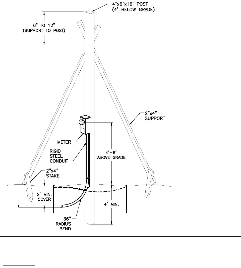
2.7. Temporary Overhead Service
The service attachment must be able to withstand the strain of the service drop. Specifications for
temporary posts are shown in Figure 2.7.
The neutral wire must be identified with white tape.
For three-phase, open-delta service, the high leg must be identified with orange tape.
A total of 18 inches of conductor must extend out of the weatherhead.

CITY LIGHT REQUIREMENTS FOR ELECTRIC SERVICE CONNECTION 2024 EDITION | PAGE 8
Figure 2.7. Typical Overhead Temporary Service Pole
CITY LIGHT REQUIREMENTS FOR ELECTRIC SERVICE CONNECTION 2024 EDITION | PAGE 9
2.8. Temporary Underground Service
Customer must install a conduit riser at the temporary panel location and trench to the City
Light-designated service stub, handhole, vault, or service pole. Figure 2.8 shows the basic pole and trench
specifications.
Figure 2.8. Typical Underground Temporary Service Pole
For more information on underground service on private property, see City Light Construction Standard
0224.01, Customer Requirements for Underground Secondary Service, Looped Radial System and City Light
Construction Standard 0224.07,“Requirements for Secondary Conduit Installation in the Standards for
Electric Service.
CITY LIGHT REQUIREMENTS FOR ELECTRIC SERVICE CONNECTION 2024 EDITION | PAGE 10
3. Looped Radial Service
3.1. Introduction
“Looped Radial” refers to the City Light distribution system that comprises the entire service territory
outside of the Network areas. It has underground service and underground areas (such as business
districts and certain residential areas), but the primary source of wires that feed these customers are from
overhead distribution poles.
3.2. Availability of Service
Individual structures must typically be serviced by a single service drop. If the customer requires
additional amperage to an existing structure, the customer must upgrade the existing service. If the
customer requires a different voltage, they may provide the transformation from the voltage provided by
City Light. Please see table 3.3, “Available Service Voltages and Maximum Secondary Service Entrance
Ratings” for more information.
City Light may provide additional secondary services to development sites in some circumstances, for
example:
• To allow for an additional secondary voltage to serve the same site if a pole or
underground facility is available to accommodate the necessary equipment. If City
Light needs to add equipment to the distribution system to provide a second service,
the customer will be billed the full cost of that addition, including the equipment.
• If site has need for physically separated point of service not intended to serve its
main structure(s) or operation.
Additional service drops must not be attached to, or feed equipment in, buildings with existing electrical
service, and must not be bridled. (See Glossary.)
For an additional primary feed with a different voltage on an existing site, the customer must install a load
break vault with the second primary run feeding a separate vault or pad mount transformer cabinet.
City Light may require a utility easement for placement of equipment that will be owned and maintained
by the utility. It is the customer’s responsibility to provide legal description(s) and a professional approved
surveyed drawing of the property. City Light will secure the easement at the customer’s expense. See
Section 1.6.8 for more information.

CITY LIGHT REQUIREMENTS FOR ELECTRIC SERVICE CONNECTION 2024 EDITION | PAGE 11
3.3. Modifications to Existing Electric Service
Certain elective modifications made to a customer’s electric service will require the customer to bring the
entire electric service (this means all existing service equipment) up to current City Light construction
standards.
Examples include:
• New meter base
• Change of meter location
• Any increase to the capacity of the service (e.g., panel upgrade, service
entrance/feeder conductor size, etc.)
• Additional meter(s)
• Legal dwelling units (e.g., ADUs; see Glossary)
Any modifications to underground-fed services that have existing direct-buried cable will require the
installation of a new conduit run in accordance with SCL 1561.05. City Light will provide a drawing
specifying the route of the conduit required for the installation. All work associated with trenching,
backfill, and restoration must be completed by, and at the expense of, the customer. See Section 1.7.
For information on charges related to modifications, see Section 1.5.

CITY LIGHT REQUIREMENTS FOR ELECTRIC SERVICE CONNECTION 2024 EDITION | PAGE 12
3.4. Available Service Voltages and Maximum Secondary Service Entrance Ratings
Table 3.4 shows the available service voltages and corresponding maximum secondary service entrance
ratings for service in the Looped Radial system.
TABLE 3.4. AVAILABLE SERVICE VOLTAGES AND MAXIMUM SECONDARY SERVICE
ENTRANCE RATINGS
Single-Phase Service Voltage (V)
Service
Maximum Secondary Service Rating (A)
b
120/240
Primary and Secondary
600
240/480
Primary and Secondary
300
Three-Phase Service Voltage (V)
120/208Y
Primary and Secondary
1000
120/240 Open Delta
a
Primary and Secondary
600
277/480Y
Primary and Secondary
600
240/480 Open Delta
a
Primary and Secondary
300
2400/4160Y
Primary only
Not applicable
7960/13,800Y
Primary only
Not applicable
15,420/26,400Y
Primary only
Not applicable
Notes:
a
The maximum allowable secondary service ampacities indicated in the table represent the total single-phase and
three-phase loads combined. The customer will be required to connect all single-phase loads across the grounded phase,
unless otherwise agreed to by City Light.
b
Primary service does not have maximum service ratings.
If service ampacity exceeds 600 A, City Light may require an underground service. At City Light’s option, an exception to
the maximum service amperes may be granted for 120/208Y service in buildings that are exclusively for residential
occupancy. This exception will be in writing.
Single-phase, three-wire and three-phase, four-wire service can be provided. Three-phase, three-wire
service is not available at any voltages.
T
he service rating must be determined by the nameplate ampere rating of the main service disconnect. In
the absence of a single main service disconnect, City Light will determine the service rating by the
nameplate rating of the main service bus or the rating of the main busing in the service entrance panel,
whichever applies.
In buildings where multiple services are connected from one service drop or service lateral, the service
rating for the building will be the aggregate of the individual service ratings.
Services to larger buildings, commercial office buildings and apartment buildings may have large electrical
services where the aggregate service entrance capacity exceeds the allowed maximum secondary service
size listed in Table 3.3. For these services, the customer must provide a vault or pad on private property
for City Light transformer(s) and associated service equipment. See Section 3.7, Primary Service.
Transformers connected to the City Light distribution system will be furnished, installed and maintained
by City Light.

CITY LIGHT REQUIREMENTS FOR ELECTRIC SERVICE CONNECTION 2024 EDITION | PAGE 13
If the customer requires a voltage other than the stated standard voltages, the customer must supply the
equipment required. All special transformation equipment must be installed on the load side of the meter,
unless otherwise agreed to in writing.
Vaults, pads, and termination facilities must be furnished by the customer in accordance with City Light
standards and other codes pertaining to the corresponding Authority Having Jurisdiction.
3.5. Clearances
All projects must meet the requirements for clearances from utility equipment as specified in SCL 0100.02,
SCL 0100.03, SCL 0100.04, SCL 0100.05, and SCL 0214.00.
For more information on clearances, see City Light Construction Standard 0100.02, Clearances Between SCL
Overhead Distribution Assets and Ground Surfaces; City Light Construction Standard 0100.03, Clearances
Between SCL Overhead Distribution Assets and Non-SCL Structures, Except Bridges; City Light Construction
Standard 0100.04, Radial Clearance Between 26 kV Overhead Distribution Conductors and Buildings; City
Light Construction Standard 0100.05, Clearances Between SCL Overhead Distribution Assets and Bridges;
and City Light Construction Standard 0214.00; Clearances Between SCL Underground Assets and Non-SCL
Structures and Objects in the Standards for Electric Service.
3.6. Water Entry Prevention
The customer is responsible for the following measures to avoid water entry into buildings and service
equipment:
• System design that considers elevation differences and other factors that would
cause a problem. The design should prevent water from entering the building or
electrical equipment to prevent electrical hazard or property damage. A City Light
Representative can advise the customer in this concern.
• Watertight grouting of conduit where it enters the building, the vault, or the
handhole.
• Watertight conduit sealing for customer/contractor-installed conductors to prevent
water from entering the service conduits. The vault interior must remain dry. The
customer must prevent water from entering the vault.
3.7. Secondary Service
“Secondary service” is defined as service that can be served from a transformer located in the public
right-of-way on a pole, on a pad, or in a vault.
Secondary service can be either overhead or underground, single-phase or three-phase.
Most single-family residential service in the City Light system is single-phase; however, there are instances
where three-phase service is available.

CITY LIGHT REQUIREMENTS FOR ELECTRIC SERVICE CONNECTION 2024 EDITION | PAGE 14
Some local jurisdictions regulate the type of services allowed within their boundaries (overhead vs.
underground). The customer must contact the Authority Having Jurisdiction to verify allowable types of
service.
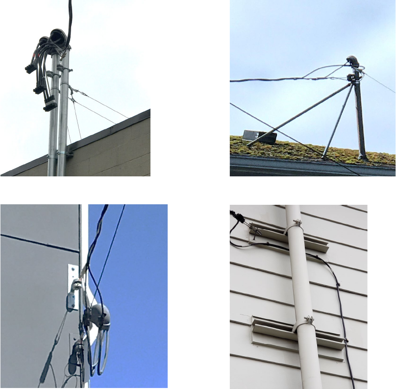
3.7.1. Secondary Overhead Services
Types of secondary overhead service include service mast with and without supporting wires, and
wall-mounted.
Neutral must be identified with white tape, high leg identified with orange tape, and three-phase circuits
identified appropriately.
The distance between weatherheads served from the same service drop must not exceed 24 inches.
Service entrance conductor sets must have a minimum of 18 inches of wire extending from the
weatherhead. If multiple service masts are installed, a minimum of 30 inches of wire must be extended
from the weatherhead.
Customer must establish a 3-ft radius of clear space along the path between the utility pole and the strike
point on the building.
Service conductors must be free of trespass of neighboring properties.
The point of attachment must be between 12 and 20 feet above grade, with the drip loop a minimum of
11 feet above grade.
For more information on service drop clearances, see City Light Construction Standard 0130.30, Secondary
Service Drops in the Standards for Electric Service.
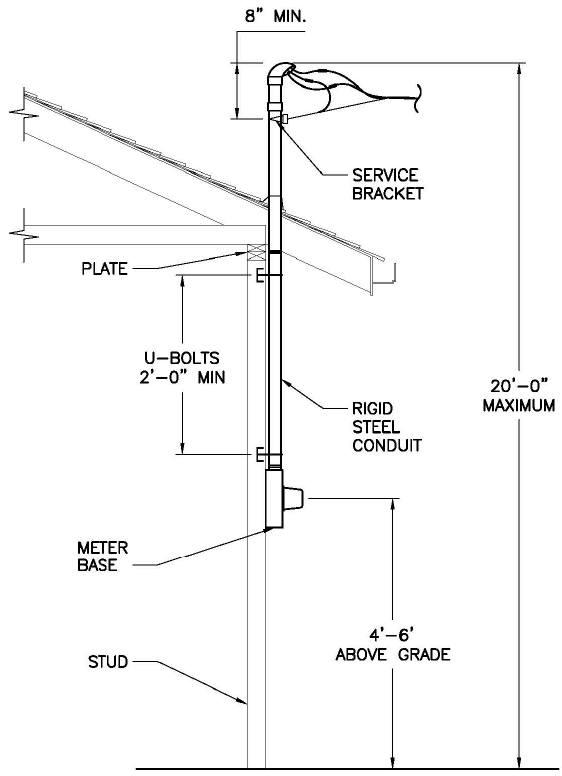
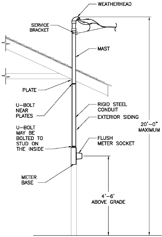
3.7.1.1 Service Mast Installation
Service mast installation for overhead service entrances may be surface-mounted or flush-mounted.
The customer must provide all the equipment shown in figures 3.7.1.1a and 3.7.1.1b except the City
Light-provided meter, which plugs into the customer’s meter socket.
Flush mounted meter sockets require a cover inspection by a City Light Representative. See Figure
3.7.1.1b.
A back guy or a stiff-leg set is required if the height between the top of the weatherhead and where the
mast clears the roofline exceeds 26 inches or the service drop exceeds 100 feet. See figures 3.7.1.1c and
3.7.1.1d.
City Light-approved service brackets must be furnished and installed by the customer. Brackets and their
attachments need to be capable of withstanding the tension of the service wires. The point of attachment
must be between 12 and 20 feet above grade. See Figure 3.7.1.1e.
For service masts where the bracket is attached to the mast, rigid steel conduit with two points of
attachment is required. Single-phase services must have a minimum 2-inch conduit, three-phase services
must have a minimum 3-inch conduit. The service mast must be within 3 feet of the roof edge.
CITY LIGHT REQUIREMENTS FOR ELECTRIC SERVICE CONNECTION 2024 EDITION | PAGE 15
The service bracket must be a minimum of 18 inches above the roofline, and no closer than 8 inches from
the weatherhead.
Roof brackets are not allowed.
Service masts must be attached to the structure at two points at least 2 feet apart.
Attachment methods may include the following:
• Kindorf brackets on the exterior of the building.
• U-bolts into a 2 in x 6 in board mounted to studs.
See Figure 3.7.1.1f.
Roof penetrations (e.g., eaves, fascia, etc.) must not be used as an attachment point.
Figure 3.7.1.1a. Surface-Mounted Service Mast Installation
CITY LIGHT REQUIREMENTS FOR ELECTRIC SERVICE CONNECTION 2024 EDITION | PAGE 16
Figure 3.7.1.1b. Flush-Mounted Service Mast Installation
CITY LIGHT REQUIREMENTS FOR ELECTRIC SERVICE CONNECTION 2024 EDITION | PAGE 17
Figure 3.7.1.1c. Back Guy
Figure 3.7.1.1d. Stiff Leg Set
Figure 3.7.1.1.e. Service Bracket
Figure 3.7.1.1f. Kindorf Bracket Attachment
3.7.1.2 Wall-Mounted Service Installation
All wall-mounted service brackets and Kindorf brackets must be secured by lag screws, 3/8 in x 4 in
minimum, into solid wood, or 3/8-in bolts through 2-in minimum solid wood.
The point of attachment must be between 12 and 20 feet above grade, with the drip loop a minimum of
11 feet above grade.
The distance from the service bracket to the weatherhead(s) must not exceed 24 inches. See Figure 3.7.1.2.
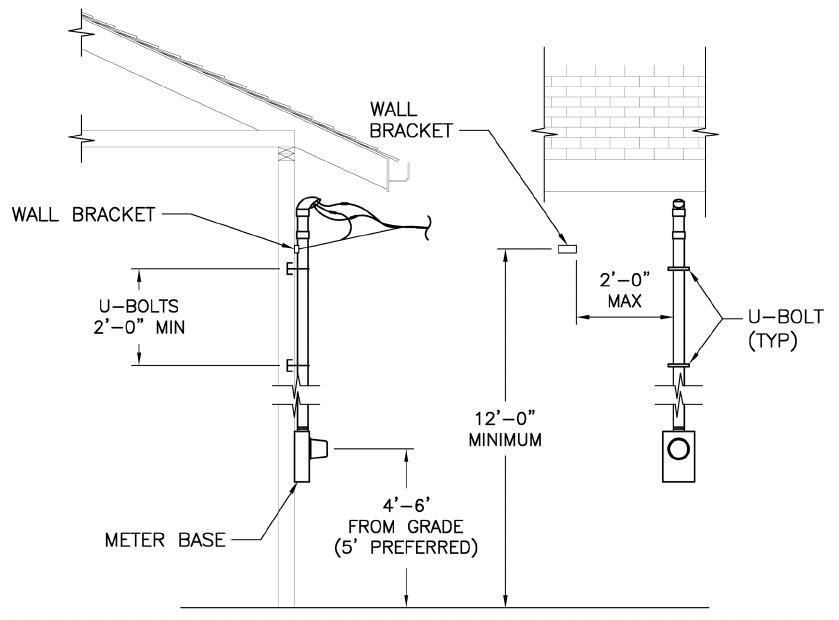
CITY LIGHT REQUIREMENTS FOR ELECTRIC SERVICE CONNECTION 2024 EDITION | PAGE 18
Figure 3.7.1.2. Wall-Mounted Service Installation
3.7.1.3 Service Poles and Guys
Service poles are: (1) poles that serve only one customer, and (2) are located on the customer’s property.
City Light may require a service pole on the customer’s property where:
• The distance from the City Light distribution pole to the customer’s point of service
attachment is greater than 150 feet.
• A clear, direct route without trespass is not available for the service drop from the
distribution pole to the customer’s point of service attachment.
Note: City Light must have a 12-ft-wide access road to set a pole on private property. If this
space is not available, services will need to be located underground. See Section 3.7.2.
• The applicable code authority requires a service pole.
City Light will install guys on service poles as needed.
CITY LIGHT REQUIREMENTS FOR ELECTRIC SERVICE CONNECTION 2024 EDITION | PAGE 19
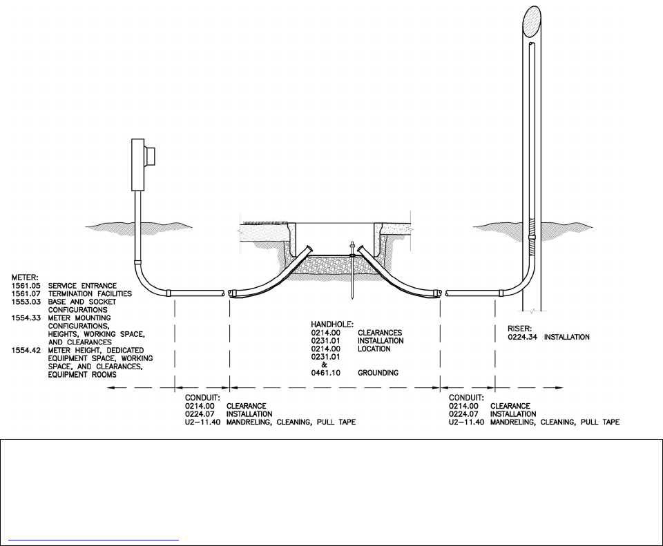
3.7.2. Secondary Underground Services
All secondary underground service shall be installed in accordance with SCL 1561.05.
C
ity Light will install the service conductors from the designated point of termination on the customer’s
property to the City Light facility in the right-of-way or easement area.
It
is the customer’s responsibility to ensure required clearances between City Light underground
structures and other utilities’ structures, and to trench up to and expose the location of entry into the SCL
facility. A City Light Electrical Reviewer or Underground Crew must supervise the last five feet of conduit
installation. Under no circumstances shall a customer or contractor enter an energized facility.
A City Light Electrical Reviewer or Underground Crew must supervise the final 5 feet of trenching to any
energized City Light vault or handhole.
Figure 3.7.2 provides a visual guide to all the City Light standards that govern the City Light underground
secondary service.
Figure 3.7.2. Guide to Underground Secondary Service Standards
For more information on installing secondary underground services, see City Light Construction Standard
1561.05, Underground Residential Service Entrances; City Light Construction Standard 0224.01, Customer
Requirements for Underground Secondary Service, Looped Radial System; and City Light Construction
Standard 0214.00, Clearances Between SCL Underground Assets and Non-SCL Structures and Objects in the
Standards for Electric Service.

CITY LIGHT REQUIREMENTS FOR ELECTRIC SERVICE CONNECTION 2024 EDITION | PAGE 20
3.8. Primary Service
Primary service is any service that exceeds the maximum secondary service capacity shown in Table 3.3.
These services require transformers or primary metering enclosures to be located in vaults or on pads
located on the customer’s property.
The customer is required to be aware of and satisfy all applicable building codes for the City of Seattle as
well as other cities and county jurisdictions in the City Light service area.
Table 3.8 shows the City Light construction standards corresponding to transformer location.
TABLE 3.8. CONSTRUCTION REQUIREMENTS BY TRANSFORMER LOCATION
Transformer Location
City Light Standards (see
Standards for Electric Service
)
Vault inside building SCL 0751.00, “Customer Requirements, In-Building Transformer Vaults, Network
and Looped Radial Systems”
SCL 0751.60, “Concurrent Customer Requirements, In-Building Transformer Vaults”
Vault outside building SCL 0732.50, “Customer Requirements for Below-Grade Transformer Service Vaults,
Looped Radial System”
Concrete pad outside building SCL 0724.50; Customer Requirements for Padmount Transformer Services, Looped
Radial System”
Note: Dimensions of the transformer vault or pad are determined by City Light and are contingent on:
• The capacity of transformer(s) to be installed. Transformer size is determined by the customer’s total electrical
load and aggregate service entrance capacity.
• The type of devices used for secondary connection to the customer’s NEC-sized service entrance equipment.
• The working clearance needed around the equipment.
All vault and pad-mounted transformers must be located to provide safe access and code clearances from
fire escapes, combustible materials, and other hazards. Building owners must make provisions to prevent
unwanted debris from accumulating in and around vaults and pads.
The customer must contact City Light well in advance of building design to receive the necessary
requirements. These specifications will be provided by City Light in the Service Construction Letter after
reviewing the customer’s plans.

CITY LIGHT REQUIREMENTS FOR ELECTRIC SERVICE CONNECTION 2024 EDITION | PAGE 21
3.8.1. Water Entry Prevention
The customer is responsible for the following measures to avoid water entry into buildings and service
equipment:
• System design that considers elevation differences and other factors that would
cause a problem. The design should prevent water from entering the building or
electrical equipment to prevent electrical hazard or property damage. A City Light
Representative can advise the customer in this concern.
• Watertight grouting of conduit where it enters the building, the vault, or the
handhole.
• Watertight conduit sealing for customer/contractor-installed conductors to prevent
water from entering the service conduits. The vault interior must remain dry. The
customer must prevent water from entering the vault.
3.8.2. Vault Access
The customer must provide properly supported, unobstructed access from the right-of-way to the vault
for City Light equipment handling machinery to deliver all necessary equipment. In-building vaults must
not be located more than one floor below the building’s exterior finished grade and must have elevator
access.
For all properties with an in-building vault, and for properties where below grade vaults and transformer
pads are located such that the customer cannot meet the requirements spelled out above, a City Light
Equipment Transportation Agreement (ETA) must be signed by the property owner.
An ETA is a legal document in which the building owner(s) take sole responsibility for moving the
transformer(s) into and out of the vault, to a mutually agreed-upon location from which City Light is able
to deliver or pick up the transformer(s) using our normal transportation methods and equipment.
All ETAs will be recorded on the property title at the property owner’s expense, as all future owners are
obligated to the same terms and conditions of the agreement. Any damage occurring to the
transformer(s) during transportation by the building owner(s) and any additional expense incurred
because of said damage must be paid by the building owner(s).
A copy of the ETA must be kept in the vault, permanently installed in a document enclosure on the vault
wall beneath the light switch. The customer must provide and install a weatherproof enclosure large
enough to hold a paper copy of the ETA.
For vault construction requirements, see: City Light Construction Standard 0751.00, “Construction
Requirement, In-Building Transformer Vaults, Network and Looped Radial Systems” and City Light
Construction Standard 0751.60, “Concurrent Customer Requirements, In-Building Transformer Vaults” in the
Standards for Electric Service.

CITY LIGHT REQUIREMENTS FOR ELECTRIC SERVICE CONNECTION 2024 EDITION | PAGE 22
3.9. Fire Clearance
All vault and pad-mounted transformers must be located to provide safe access and code clearances from
fire escapes, combustible materials, and other hazards. This is necessary to comply with the fire clearance
requirements of City Light and the appropriate City, County, or State inspecting authorities. Building
owners must make provisions to prevent unwanted debris from accumulating in and around vaults and
pads.
The customer must contact City Light well in advance of building design to receive the necessary
requirements. These specifications will be provided by City Light in the Service Construction Letter after
reviewing the customer’s plans.
3.10. Vibration and Noise Levels
The customer is responsible for isolating the transformer vault or pad so that sound and vibration levels
satisfy the applicable laws and ordinances of the Washington Administrative Code (WAC), the City of
Seattle, or other applicable jurisdictions, including the customer’s own requirements. Further, it is the
customer’s responsibility to mitigate any magnetic field effects from any customer-owned sensitive
equipment.
3.11. Elevators
Elevator service must be provided to any building level where a transformer vault is located.
3.12. Special Services
3.12.1. Mobile Home Parks
City Light will supply one service to a mobile home park per Seattle Municipal Code 21.49.100
, Paragraph
H, Section 2. Installation and maintenance beyond the service connection point will be the owner’s
responsibility. Meter locations must be accessible, and meters grouped. See Chapter 6, Metering, for more
information.
3.12.2. Mobile Homes on Individual Owner Lots (not part of a mobile home community)
Mobile home installations that are not part of a mobile home community will require a service pole and
meter socket that is not attached to the mobile home, per NEC requirements.
3.12.3. Houseboat Piers
City Light service for houseboats must be terminated on shore. The termination equipment must also be
approved by City Light.
City Light will not upgrade existing overhead distribution on houseboat piers. If additional loads require
upgrading of houseboat pier electrical distribution, it is the customer’s responsibility to do so.

CITY LIGHT REQUIREMENTS FOR ELECTRIC SERVICE CONNECTION 2024 EDITION | PAGE 23
3.12.4. Boat Moorages
New or upgraded service to boat mooring establishments must be master metered per
Seattle Municipal
Code 21.49.100, Paragraph H, Section 1. See Chapter 6, Metering for more information.
3.12.5. Unit Lot Subdivisions
For unit lot subdivisions, the parent parcel is considered one development site. Service entrance
conductors must be combined in such a way that all structures on the parent parcel can be served from
one service drop or service lateral directly from the City Light distribution system. The design of the
distribution system to serve the site must be within the sole discretion of City Light. No bridled services
will be allowed.
Per Seattle Municipal Code 23.24.045 (F)
, the unit lots created by unit lot subdivision are not separate
buildable lots. Development standards will be applied to the original parcel and not to each of the new
unit lots. As a result, the electrical service to an existing structure may need revision to meet current City
Light standards and requirements for the development site.
This applies to cases where new buildings (SFRs, Townhomes) are constructed and added to sites that
have existing buildings.
CITY LIGHT REQUIREMENTS FOR ELECTRIC SERVICE CONNECTION 2024 EDITION | PAGE 24
4. Network Services
4.1. Introduction
Network service areas are designed to provide redundancy and continuity of service in the case of
outages and include protective devices to prevent backfeed onto the grid. Because of this, there are
special rules for customer generation. Please see Chapter 5, “Distributed Energy Resources,” for more
information.
City Light has four network service areas: Downtown, First Hill, University District, and the South Lake
Union Area.
Secondary services in network areas are served from street networks, where the transformers and related
equipment are located in facilities in the right of way. Primary services are served from spot networks,
where the facilities are located on the property of the service.
This chapter includes general guidelines for service installations in network areas. Customers must contact
City Light well in advance of the project starting to receive the required design specifications.
4.2. Availability of Service
Individual structures will typically be serviced by a single service drop. If the customer requires additional
amperage to an existing structure, the customer must upgrade the existing service. If the customer
requires a different voltage, they may provide the transformation from the voltage provided by City Light.
Please see table 3.3, “Available Service Voltages and Maximum Secondary Service Entrance Ratings” for
more information.
City Light may provide additional secondary services to development sites in some circumstances, for
example:
• To allow for an additional secondary voltage to serve the same site if a pole or
underground facility is available to accommodate the necessary equipment. If City
Light needs to add equipment to the distribution system to provide a second service,
the customer will be billed the full cost of that addition, including the equipment.
• If site has need for physically separated point of service not intended to serve its
main structure(s) or operation.
Additional service drops must not be attached to, or feed equipment in, buildings with existing electrical
service, and must not be bridled. (See Glossary.)
For an additional primary feed with a different voltage on an existing site, the customer must install a load
break vault with the second primary run feeding a separate vault or pad mount transformer cabinet.
City Light may require a utility easement for placement of equipment that will be owned and maintained
by the utility. It is the customer’s responsibility to provide legal description(s) and a professional approved
surveyed drawing of the property. City Light will secure the easement at the customer’s expense. See
Section 1.6.8 for more information.

CITY LIGHT REQUIREMENTS FOR ELECTRIC SERVICE CONNECTION 2024 EDITION | PAGE 25
4.3. Clearances Between SCL Underground Structures and Other Structures
All projects must meet the requirements for clearances between SCL underground structures and other
structures as specified in SCL 0214.00.
For more information, see City Light Construction Standard 0214.00; Clearances Between SCL Underground
Assets and Non-SCL Structures and Objects in the Standards for Electric Service.
4.4. Permitting and Inspections
See Section 1.7.
4.5. Service Notes, General
All services in the Network system are underground.
Sin
gle-phase, three
-wi
re and three
-p
hase, four
-wi
re service can be provided. Three
-p
hase, three
-wi
re
service is not available at any voltages.
T
he service rating must be determined by the nameplate ampere rating of the main service disconnect. In
the absence of a single main service disconnect, City Light will determine the service rating by the
nameplate rating of the main service bus or the rating of the main busing in the service entrance panel,
whichever applies.
In buildings where multiple services are connected from one service drop or service lateral, the service
rating for the building must be the aggregate of the individual service ratings.
Table 4.5 shows the available service voltages and corresponding maximum service entrance ratings for
secondary service in Network Areas.
TABLE 4.5. AVAILABLE SERVICE VOLTAGES AND MAXIMUM SECONDARY SERVICE ENTRANCE
RATINGS FOR NETWORK AREAS
Single-Phase Service Voltage (V)
Maximum Secondary Service Rating (A)
120/208
200
277/480
100
Three-Phase Service Voltage (V)
120/208Y
1000
277/480Y
600
a
The maximum allowable service ampacities indicated in the table represent the total single-phase and three-phase
loads combined. The customer will be required to connect all single-phase loads across the grounded phase, unless
otherwise agreed to by City Light.
Services to larger buildings, commercial office buildings and apartment buildings may have large electrical
services where the aggregate service entrance capacity exceeds that allowed maximum secondary service
size listed in Table 4.5. For these services, the customer must provide a vault on private property for City
Light transformer(s) and associated service equipment. Such a vault for City Light transformer(s) must be
located on the site being serviced, or in an easement area on private property.

CITY LIGHT REQUIREMENTS FOR ELECTRIC SERVICE CONNECTION 2024 EDITION | PAGE 26
4.6. Vault Construction
For vault construction requirements, see City Light Construction Standard 0751.00, “Construction
Requirement, In-Building Transformer Vaults, Network and Looped Radial Systems” and City Light
Construction Standard 0751.60, “Concurrent Customer Requirements, In-Building Transformer Vaults” in the
Standards for Electric Service.
Dimensions of the transformer vault are determined by City Light and are contingent on:
• The capacity of transformer(s) to be installed. Transformer size is determined by the
customer’s total electrical load and aggregate service entrance capacity.
• The type of devices used for secondary connection to the customer’s NEC-sized
service entrance equipment.
• The working clearance needed around the equipment.
4.7. Water Entry Prevention
The customer is responsible for the following measures to avoid water entry into buildings and service
equipment:
• System design that considers elevation differences and other factors that would
cause a problem. The design should prevent water from entering the building or
electrical equipment to prevent electrical hazard or property damage. A City Light
Representative can advise the customer in this concern.
• Watertight grouting of conduit where it enters the building, the vault, or the
handhole.
• Watertight conduit sealing for customer/contractor installed conductors to prevent
water from entering the service conduits. The vault interior must remain dry. The
customer must prevent water from entering the vault.
4.8. Vault Access
The customer must provide properly supported, unobstructed access from the right-of-way to the vault
for City Light equipment handling machinery to deliver all necessary equipment. In-building vaults must
not be located more than one floor below the building’s exterior finished grade and must have elevator
access.
For all properties with an in-building vault, and for properties where below grade vaults and transformer
pads are located such that the customer cannot meet the requirements spelled out above, a City Light
Equipment Transportation Agreement (ETA) must be signed by the property owner.
An ETA is a legal document in which the building owner(s) take sole responsibility for moving the
transformer(s) into and out of the vault, to a mutually agreed-upon location from which City Light is able
to deliver or pick up the transformer(s) using our normal transportation methods and equipment.
CITY LIGHT REQUIREMENTS FOR ELECTRIC SERVICE CONNECTION 2024 EDITION | PAGE 27
All ETAs will be recorded on the property title at the property owner’s expense, as all future owners are
obligated to the same terms and conditions of the agreement. Any damage occurring to the transformer
during transportation by the building owner(s) and any additional expense incurred because of said
damage must be paid by the building owner(s).
A copy of the ETA must be kept in the vault. The customer must provide and install a weatherproof
enclosure large enough to hold a paper copy of the ETA. The ETA must be permanently installed in a
document enclosure on the vault wall beneath the light switch.
4.9. Fire Clearance
All vault and pad mounted transformers must be located to provide safe access and code clearances from
fire escapes, combustible materials, and other hazards. This is necessary to comply with the fire clearance
requirements of City Light and the appropriate City, County, or State inspecting authorities. Building
owners must make provisions to prevent unwanted debris from accumulating in and around vaults and
pads.
The customer must contact City Light well in advance of building design to receive the necessary
requirements. These specifications will be provided by City Light in the Service Construction Letter after
reviewing the customer’s plans.
4.10. Vibration and Noise Levels
The customer is responsible for isolating the transformer vault or pad so that sound and vibration levels
satisfy the applicable laws and ordinances of the Washington Administrative Code (WAC), the City of
Seattle, or other applicable jurisdictions, including the customer’s own requirements. Further, it is the
customer’s responsibility to mitigate any magnetic field effects from any customer-owned sensitive
equipment.
4.11. Elevators
Elevator service must be provided to any building level where a transformer vault is located.
4.12. NEC-Sized Service Entrances in Network Areas
The maximum size of an NEC cable allowed to enter a vault is 750 kcmil.
Depending on transformer size, City Light may terminate a maximum of six (6) sets of NEC-sized cables
directly on the transformer secondary terminals.

CITY LIGHT REQUIREMENTS FOR ELECTRIC SERVICE CONNECTION 2024 EDITION | PAGE 28
4.13. Secondary Service
The aggregate service ampacity must be limited to 1000 A at 120/208Y, or 600 A at 277/480Y, depending
on which is available.
Where the service entrance ampacity exceeds 200 A at 120/208Y or 100 A at 277/480Y, the service must
be three-phase, four-wire, and the load must be balanced.
The customer must install the necessary conduit to the City Light-designated point of termination. City
Light will extend this conduit to the City Light service handhole or vault and install service conductors to
the point of service connection designated by City Light.
TABLE 4.13. REQUIREMENTS FOR RESIDENTIAL AND MULTI-FAMILY SERVICE IN
NETWORK AREAS
Single-Phase Service Voltage (V)
Requirement(s)
120/208 up to 200 A The customer must install service conduit to a City Light-designated
point on the property line.
277/480Y up to 100 A
The customer must install service conduit to a City Light-designated
point on the property line.
Three-Phase Service Voltage (V)
120/208Y greater than 1000 A The customer must supply a transformer vault or space on the premises
for our transformer(s), as well as service conduits to the property line as
specified by City Light. The transformer vault must be approved by City
Light and must be in compliance with City Light electrical and building
codes.
277/480Y greater than 600 A The customer must supply a transformer vault or space on the premises
for our transformer(s), as well as service conduits to the property line as
specified by City Light. The transformer vault must be approved by City
Light and must be in compliance with City Light electrical and building
codes.
4.14. Primary Service
Contractors must notify City Light well in advance of designing their buildings, as the requirements for
primary service may alter the building design. For example, City Light may require space not only for the
vault, but for a primary switchgear room as well.
Where the aggregate service entrance capacity exceeds 1000 A at 120/208Y or 600 A at 277/480Y, the
customer must provide a vault or other suitable facilities on private property for the City Light
transformer(s) and associated service equipment. Such vault or other facility for Utility transformer(s) must
be located on the site being served.
Services greater than 600 A at 277/480Y will be required to be spot networks. They cannot be served from
the adjacent street network.
CITY LIGHT REQUIREMENTS FOR ELECTRIC SERVICE CONNECTION 2024 EDITION | PAGE 29
4.15. Fault Current Limiters
When the customer installs fault current limiters on the line side (the City Light side) of the first disconnect
or main breaker, the customer must install a current limiter enclosure that meets the requirements below:
The enclosure must be sealable and separate from our service termination point. The customer’s
weatherhead, service terminal box, meter socket, and current transformer enclosures are not acceptable
locations for current limiters.
The current limiter enclosure must be clearly marked “Fault Current Limiters,” and it may not be used for
any other purpose, such as a connection point for taps or extensions.
The customer is responsible for maintaining and replacing fault current limiters. If repair or maintenance
operations require City Light to temporarily disconnect the service, the customer will be billed for this
labor. After any maintenance operation, the customer must notify City Light for replacement of meter
seals.

CITY LIGHT REQUIREMENTS FOR ELECTRIC SERVICE CONNECTION 2024 EDITION | PAGE 30
5. Distributed Energy Resources
A distributed energy resource (DER) refers to equipment that is owned by the customer, capable of
operating in parallel with the City Light electrical grid and located on the customer’s side of the point of
termination. DERs can include electrical generation systems (solar, wind, fossil fuel, etc.), energy storage
systems (batteries, etc.), and microgrids.
If sources of power generation or energy storage are configured so they may never operate in parallel to
the City Light electrical grid, they are not referred to as DERs, and this chapter is not pertinent. Instead,
they will be considered emergency backup equipment, the requirements for which are described in
Chapter 8.
5.1. Overview of the Interconnection Process
All customers who seek interconnection of a DER with the City Light electrical grid must submit an
Application for Electric Service, obtain utility approval, and sign an interconnection agreement with City
Light prior to commencing generation from their DER. Interconnection (see Glossary) involves a multi-step
technical, administrative, and financial process to enable a DER to safely and reliably connect and
exchange power with a utility’s electrical grid.
Steps in City Light’s DER interconnection process are described below and displayed in a simplified form
in Figure 5.1. Where customer actions are noted, a DER installation firm can perform the actions on the
customer’s behalf if the installation firm is listed on the customer’s application.
1. The customer completes and submits an interconnection application and agreement along
with an online electric service application, which can be found on the
Apply for New or
Upgraded Electric Service page on the City Light website. Necessary attachments (i.e., electrical
one-line riser diagram, site plan or other notation of where the proposed DER will be placed
on the customer premises, equipment specification sheet(s), and customer-signed
interconnection agreement) must also be provided to City Light.
2. City Light reviews the application and attachments for completeness and contacts the
customer if any clarifications or additional materials are required.
3. If requested by City Light, the customer submits additional information.
4. If needed (see Section 5.3), City Light performs an engineering review, including identifying
any new interconnection facility or system upgrade costs that must be paid by the customer to
accommodate the proposed DER. City Light may contact the customer at this step if updated
information is needed for a successful review. Following receipt of that information, City Light
may re-perform the engineering review.

CITY LIGHT REQUIREMENTS FOR ELECTRIC SERVICE CONNECTION 2024 EDITION | PAGE 31
5. For Level 2-4 interconnection applications (applicable to proposed DER with nameplate
capacity above 100 kilowatts [kW]), City Light countersigns the interconnection agreement and
returns it to the customer. This step is not applicable to Level 1 interconnection applications.
See DPP 500 III-305, Standards for Interconnection of Generators 20 MW and Less in Capacity
for each definition level.
6. The customer, at their own expense, obtains all permits and authorizations, as outlined in
Section 1.7. City Light encourages the customer to begin these permit and authorization
activities as early as feasible to avoid unduly delaying DER commissioning.
7. If needed, based on the earlier engineering review, City Light conducts the design and
construction of new facilities or system upgrades after the customer pays for such
interconnection costs. This step can occur simultaneously with Step 6.
8. City Light performs its final reviews of the proposed DER, including an inspection to verify the
service meets utility requirements. As part of that inspection, City Light checks the customer
metering to ensure that a bi-directional advanced meter is installed (or to arrange installation
if it is not already installed) and checks that the metering is compliant. DER installations are
required to have an advanced meter and may not opt out of that requirement as stated in
DPP 500 III-427, Advanced Metering Opt-Out
.
9. If notified by City Light of any deficiencies in the proposed DER, the customer addresses the
deficiencies.
10. The customer can connect the DER to the City Light electric grid when it reaches this step, but
not before. This is also called energizing the DER.
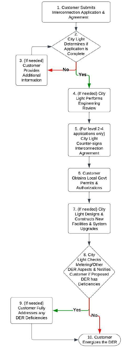
CITY LIGHT REQUIREMENTS FOR ELECTRIC SERVICE CONNECTION 2024 EDITION | PAGE 32
Figure 5.1. List of Steps in the DER Interconnection Process
A customer may withdraw their application at any time in the process if they no longer wish to pursue
interconnection of their proposed DER with the City Light electrical grid.

CITY LIGHT REQUIREMENTS FOR ELECTRIC SERVICE CONNECTION 2024 EDITION | PAGE 33
5.2. Utility Programs for Distributed Energy Resources
City Light offers two main programs that establish financial compensation rules for electricity produced by
qualifying DERs in excess of customer on-site electricity consumption: the net metering program and the
large solar program. Customers must complete the interconnection process to be eligible for either
program. City Light’s DER programs and compensation rates are subject to change.
Under the net metering program, solar and other qualifying DER types receive kilowatt-hour (kWh) credits
on the customer’s utility bill for the electricity produced by the DER. These credits are rolled over intra-
year and are valued at the customer’s retail rate of electricity. For this program, DER nameplate capacity
cannot exceed 100 kW, except under certain conditions specified in Seattle Municipal Code 21.49.082
.
Under the large solar program, solar DERs with nameplate capacity above 100 kW and not exceeding
2,000 kW are eligible to participate. The program sets compensation rates for electricity exported to the
City Light electrical grid as described in Seattle Municipal Code 21.49.083
.
More information on City Light solar programs for residential and business customers can be found on
City Light’s website at
https://seattle.gov/city-light/residential-services/home-energy-solutions/solar-
power#citylightsolarprograms and https://seattle.gov/city-light/business-solutions/renewable-energy-
services/solar-programs-for-businesses#citylightsolarprograms. Customers can also contact their City
Light Representatives for information about these programs.
5.3. Engineering Review
City Light Engineering may evaluate any proposed DER for adverse impacts to the City Light electrical grid
as part of the interconnection process. If an adverse impact is determined, additional engineering analysis
will be required. This analysis may delay the commissioning of the DER installation. This analysis may also
identify new interconnection facility or system upgrades necessary to be installed at customer expense in
order for City Light to interconnect the DER safely and reliably.
Among new DER installations, there are two pathways: Pathway A (those that do not require an
engineering review), and Pathway B (those that do require an engineering review).
The types of new DER installations on Pathway B that can expect an engineering review include:
• An inverter-based resource, without an associated energy storage system, of more
than 10 kW in nameplate capacity
• A DER with an energy storage system of any size
• A machine-based generation resource of any size
• A microgrid of any size
• A DER located within a Network service area
• A DER determined to have an adverse impact to the City Light electrical grid based
on initial City Light analysis

CITY LIGHT REQUIREMENTS FOR ELECTRIC SERVICE CONNECTION 2024 EDITION | PAGE 34
All proposed, inverter-based DERs must use inverters certified under Underwriters Laboratories (UL) 1741
Supplement B (Standard for Safety Inverters, Converters, Controllers and Interconnection System
Equipment for Use With Distributed Energy Resources, Supplement B and labeled as UL1741-SB) and
Institute of Electrical and Electronics Engineers (IEEE) 1547-2018 (Standard for Interconnection and
Interoperability of Distributed Energy Resources with Associated Electric Power Systems Interfaces).
Implementation of this new inverter requirement will occur on the following schedule:
• New DER interconnection applications submitted on or after July 1, 2024, on
Pathway A (those that do not require an engineering review) must use inverters
certified under UL1741-SB.
• New DER interconnection applications submitted on or after April 1, 2024, on
Pathway B (those that do require an engineering review) must use inverters certified
under UL1741-SB.
5.4. Safety Disconnects
All DERs with a nameplate capacity of 25 kW or more must include a safety disconnect switch capable of
fully disconnecting the DER from the City Light electrical grid. The customer must furnish and install the
safety disconnect switch on the load side of the utility meter with the following characteristics, unless
otherwise approved by City Light:
• A visible break type in a metal enclosure
• Lockable in an open position by a padlock
• Labeled as “UTILITY GENERATOR DISCONNECT SWITCH” per NEC 705.20 (8) and NEC
690.13 (B)
• Labeled with warnings per NEC 110.21 (B)
• Accessible 24 hours a day to City Light personnel as defined in
Seattle Municipal
Code 21.49.110, Section N
• Mounted within sight of the DER meter(s) and no more than 10 feet from these
meter(s)
For three-phase interconnections, the safety disconnect switch must be gang-operated.
Customers with a DER having a nameplate capacity less than 25 kW and served through a self-contained
meter base are encouraged, but not required, to include a safety disconnect switch capable of fully
disconnecting the DER from the City Light electrical grid.

CITY LIGHT REQUIREMENTS FOR ELECTRIC SERVICE CONNECTION 2024 EDITION | PAGE 35
5.5. Compliance with Metering Requirements
DER metering must meet all pertinent requirements as defined in Chapters 5 and 6 (including
requirements for access and placement), the customer’s interconnection agreement with City Light, and
the rules of any City Light rates and programs under which the customer is served.
In all cases, the installation of DER equipment must meet clearance and working space requirements for
utility meters as specified in SCL 1554.33 and SCL 1554.42. Certain elective modifications made to a
customer’s electric service will require the customer to bring the entire electric service (this means all
existing service equipment, including metering) up to current City Light construction standards. See
Section 3.3.
For more information on utility-meter clearance and working space requirements, see City Light
Construction Standard 1554.33, Meter Mounting Configurations, Heights, Working Space, and Clearances,
Exterior (Outdoor) and City Light Construction Standard 1554.42,Meter Height, Dedicated Equipment Space,
Working Space, and Clearances, Equipment Rooms in the Standards for Electric Service.
5.6. Line Side Taps
Line side taps are not allowed in meter sockets or current transformer (CT) cabinets.
CITY LIGHT REQUIREMENTS FOR ELECTRIC SERVICE CONNECTION 2024 EDITION | PAGE 36
5.7. Interconnection within Network Service Areas
In addition to the requirements described throughout this chapter for DER interconnection within the City
Light Looped Radial system, there are additional requirements governing DER interconnection within City
Light Network service areas. These additional requirements help assure electric power quality and
reliability as well as the safety of City Light employees and contractors who maintain the Network service
areas and are:
• Only inverter-based resources are eligible to interconnect. Machine-based generation
resources are not eligible.
• The customer seeking interconnection within the Network service area must provide
evidence to the satisfaction of City Light that their proposed DER will never result in
reverse current flow (i.e., power export) through utility network protectors.
• Closed transition transfer switches are not allowed.
• The proposed DER must include a protective scheme as specified by City Light, and
any associated equipment will be installed at the customer’s expense. At least one of
the following protective schemes must be implemented:
o The power control system(s) (PCS) meet(s) UL 1741 Certification Requirement
Decision (CRD) for PCS and has/have been tested within that UL 1741 standard to
restrict power export. The proposed DER’s PCS shall be set to an operating mode
to restrict power export from all sources.
o The proposed DER’s nameplate capacity shall not exceed 50% of the customer’s
minimum load (i.e., daytime minimum load if the proposed DER is a standalone
solar system, or absolute minimum load for all other types of DERs including
hybrid solar + battery storage systems) over the past 12 months. If historical
customer minimum load data are not available, 5% of the customer’s maximum
load of the previous year or a good faith estimate of the customer’s minimum
load will be used.
In addition, DERs within Network service areas must meet pertinent requirements in Chapter 4.
CITY LIGHT REQUIREMENTS FOR ELECTRIC SERVICE CONNECTION 2024 EDITION | PAGE 37
6. Metering
6.1. Introduction
Electricity meters are required for all electrical services so City Light can determine customer usage for
accurate billing and for maintaining appropriate distribution to our customers.
City Light provides and installs all electricity meters for customer-installed meter sockets. This chapter
describes the requirements for equipment, location, and clearances for both simple and complex meter
installations.
City Light installs and maintains meters, instruments, transformers and associated equipment that are
located on the City Light side of the meter. City Light has ownership of this equipment. Customer-owned,
installed, and maintained equipment includes meter sockets, enclosures, landing pads, lugs, conduit, and
conductors.
City Light will determine the specific metering equipment requirements after reviewing customer plans
and/or drawings.
Drawings must be submitted and approved for customer-designed pedestals or other structures on which
the customer is proposing to mount metering or service entrance equipment. All drawings or prints
submitted to City Light must be engineering or architectural grade.
6.2. Requirements, General
6.2.1. Electric Utility Service Equipment Requirements Committee (EUSERC) Material and
Equipment Requirements
All electric service installations must be constructed of material and equipment that meet the applicable
requirements of EUSERC standards. Contact your City Light Representative for questions regarding
EUSERC.
6.2.2. Service Entrance Conductors for Metered Loads
For single meter installations, metered service conductors must not pass through any junction box,
condulet, or fitting, or have any other point of access, regardless of lockable function.
For multi-meter installations, the use of bus or wire troughs is permitted for unmetered service
conductors if the enclosures are approved, sealable, and lockable by City Light.
Unmetered service conductors must be continuous from the service connection point to the meter socket
or current transformer enclosure, or in a main disconnect for group installations.
Unmetered service conductors and metered load conductors must be run in separate conduit, raceway, or
wire trough.
Metering equipment, enclosures, and wire troughs containing unmetered service conductors and/or bus
must be sealable and lockable as determined by City Light.

CITY LIGHT REQUIREMENTS FOR ELECTRIC SERVICE CONNECTION 2024 EDITION | PAGE 38
Any equipment or switchgear compartments that afford access to unmetered service conductors or bus
must be sealable and lockable by City Light.
Metered load conductors must not pass through sealable sections, including current transformer
enclosures.
6.2.3. Conductor Connections
For aluminum conductors and connections, an oxide inhibitor must be used. The meter socket must have
lugs approved for aluminum.
When copper is used as conductor, meter terminals, and/or socket jaws, an oxide inhibitor must not be
used.
6.3. Voltages
All services must be metered at the service voltage.
Exception: 480Y/277 V, three-phase services transformed to 120/208 or 120/240 for residential
distribution in multi-
u
nit buildings is allowed.
A
ll primary voltage services (4160 V, 13,800 V and 26,400 V) must be metered at the service voltage in
accordance with the Electric Utility Service Equipment Requirements (EUSERC) standards and City Light
Construction Standards.
For voltages greater than 600 V, contact your City Light Representative for primary voltage metering
requirements.
6.4. Meter Sockets
While City Light provides and installs the meter and instrument transformers, the customer is responsible
for providing and installing the meter socket and current transformer enclosure as applicable. See Section
6.9 for Current Transformer rated service requirements.
All meter sockets must meet ANSI C12.1 and UL 414 Standards for Meter Sockets.
Meter sockets and equipment enclosures must be raintight, NEMA 3R rated if they are located outside.
It is important to refer to City Light Construction Standard 1553.03, “Meter Base and Socket Configurations”
(see Standards for Electric Service
), to identify the correct meter socket for your application in order to
avoid delays to receiving service.
Commercial services require either a block bypass or a safety socket.
Block bypass sockets are required on 400 A (class 320) residential services.
200 A residential services do not require block bypass sockets; however, they are strongly recommended.
Block bypass sockets are required on three phase services when the voltage is less than 277 V to neutral
or 480 V phase to phase.
CITY LIGHT REQUIREMENTS FOR ELECTRIC SERVICE CONNECTION 2024 EDITION | PAGE 39
Safety sockets are required when the service voltage is 277 V to neutral or 480 V phase to phase.
City Light does not allow automatic, lever type, or slide-link socket bypass devices.
City Light does not allow ringless meter sockets/bases of any type.
Sockets must be plumb and securely fastened to the supporting structure.
Unused threaded or knockout openings must be closed with an approved plug locked in place from the
inside.
Only metering taps are allowed in meter sockets. Examples of metering taps are the 5th and 7th terminal
connections to the neutral and a 5th terminal connection to the unmetered leg as in existing three-phase,
three-wire Delta services.
Line side taps are not allowed in meter sockets.
5th terminals must not be installed in 120/240 V sockets.
The line side conductors must be connected to the top terminals of the meter socket. The load side
conductors must be connected to the bottom terminals.
Exception: Production meter sockets must be wired with the line side conductors connected to
the bottom terminals, and the conductors from the generation source on the top terminals.
Flush-mounted meter sockets must be encased in concrete or require cover inspection.
Meter rings will be provided by City Light.
6.5. Location, Access, and Protection of Metering Equipment
6.5.1. Location
Single-meter sockets must be installed in an accessible location outside the building. Multiple socket
installations may be located outside or inside the building.
Metering equipment must not be installed over stairs, stairwells, steps, or public walkways. If mounted on
a balcony or platform, a fixed stairway to the area is required and must be maintained for the duration
that the service exists. Ship ladders are not allowed. For balcony or platform installations the structure
must be professionally engineered. The structure must meet all Washington Administrative Code (WAC)
requirements. City Light requires meshing be installed on the railing as an additional safeguard with the
opening not to exceed 1/2 inch.
City Light may post a Utility logo on the outside of meter room doors. City Light will inspect and approve
the customer’s choice of location for meter sockets and metering equipment prior to beginning
equipment installation. The location must be free from vibration, corrosive atmosphere, and extreme
temperatures.
Equipment rooms where meters are installed must be for the sole purpose of electrical switchgear and
metering equipment. Under no circumstances will gasoline, diesel fuel, propane, paints, or any other
noxious or hazardous materials be stored in a meter room.
CITY LIGHT REQUIREMENTS FOR ELECTRIC SERVICE CONNECTION 2024 EDITION | PAGE 40
Meter locations must not be under or over any structure which might be enclosed or removed in the
future, such as a porch, deck, carport, or stairway.
All current transformer enclosures must be installed in an accessible location outside the building or in an
approved equipment room. For residential services the current transformer enclosures must be outdoors
and accessible during normal business hours.
6.5.2. Access to Metering Equipment
City Light reserves the right to access the customer’s premises during normal business hours (Monday
through Friday, 8 AM to 4 PM) for meter reading, testing, installation, removal, inspection, and/or
maintenance of City Light equipment.
The location must be readily accessible without risk of bodily harm to City Light employees.
Access must not be blocked by either permanent or portable materials.
The area around all City Light equipment must be free from vegetation.
Any fenced/enclosed areas and/or metering cabinets/enclosures must be made accessible with a City
Light-provided key box at the owner’s expense. This lock box will be co-located with the Fire
Department’s Lock Box (where applicable). The customer must provide keys and/or key cards.
All metering equipment covers must be readily accessible. They may not be plastered, caulked, or built in,
in any way, so as to impede the opening of the meter cover or metering equipment covers including
current transformer enclosure covers or doors.
All metering equipment doors must open a minimum of 90 degrees from the front of the enclosures.
Outdoor equipment enclosure doors must have a hold open device.
6.5.3. Physical Protection of Metering Equipment
Where damage of metering equipment has or is likely to occur from vandalism, vehicles or other causes,
City Light may require the customer to install protective devices such as bollards, barriers, or enclosures at
the customer’s expense.
Pedestal metering equipment must be sturdy enough for reasonable installation or removal of a meter
without damage to the pedestal. Contact your City Light Representative for requirements.
Indoor spaces housing metering equipment must have the ambient air temperature maintained below
30 degrees C (86ºF). The customer is responsible for cost of maintenance, repairs and replacement of
meter equipment resulting from ambient temperature.

CITY LIGHT REQUIREMENTS FOR ELECTRIC SERVICE CONNECTION 2024 EDITION | PAGE 41
6.6. Meter Height, Working Space, and Clearance Requirements
All meter installations must meet the requirements as specified in SCL 1554.33 and SCL 1554.42.
For more information on meter height, working space, and clearance requirements, see City Light
Construction Standard 1554.33, Meter Mounting Configurations, Heights, Working Space, and Clearances,
Exterior (Outdoor) and City Light Construction Standard 1554.42, Meter Height, Dedicated Equipment Space,
Working Space, and Clearances, Equipment Rooms in the Standards for Electric Service.
6.7. Service Entrance Equipment Sequencing
6.7.1. Single Self-Contained Meter Installation
T
he meter socket must be installed ahead of the fused disconnect/circuit breaker. A fused
disconnect/circuit breaker cannot precede the meter except in certain multi-
u
nit installations (described
below).
Pedestal metering must not contain the customer’s main disconnect.
6.7.2. Multi-Unit Self-Contained Meter Installations
A
main disconnect/breaker may be installed ahead of the meter sockets in multi
-u
nit installations of two
or more individual sockets provided that all equipment ahead of the meters has sealing provisions.
Th
e breaker must be the common trip type, i.e., must open or close all ungrounded conductors
simultaneously. The breaker must be constructed to prevent being changed to a non
-t
rip type.
6.
8. Metering Requirements for Multi-Unit Buildings
Prior to meter installation all meter sockets must be identified with permanent labeling by final space or
unit number, letter designation, and/or street address. Meter sockets must have engraved phenolic
nameplates affixed to the socket covers. Nameplates must be placed directly beneath the meter socket on
the side closest to the disconnect switch. See Figure 6.8.
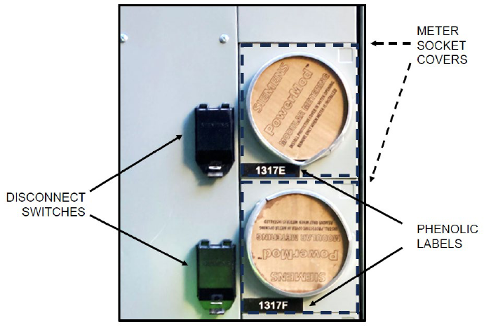
CITY LIGHT REQUIREMENTS FOR ELECTRIC SERVICE CONNECTION 2024 EDITION | PAGE 42
Figure 6.8. Phenolic Nameplate Placement
Note: Felt-tip pens and label-maker tape are not considered permanent marking.
Permanent numbering of the separately metered spaces or units is required. If it is not practical before
meter installation, the customer must provide temporary identification at the main entrance of the space
for the purpose of performing space checks.
All multi-unit services must have at least one meter for each legal dwelling unit. Where common load
exists, an additional house meter is required.
All auxiliary dwelling units without separate metering, and/or units found to have mixed or common loads
will be billed in the owner’s name.
City Light-conducted space checks are required for all new and rewired multi-unit services to verify
socket-to-unit panel wiring.
After the initial service installation, all additional space checks, address changes, and mixed-load checks
will be charged to the owner or person making the request.
Load determination will be based upon the greatest aggregate nameplate ratings of each fused
disconnect or circuit breaker.
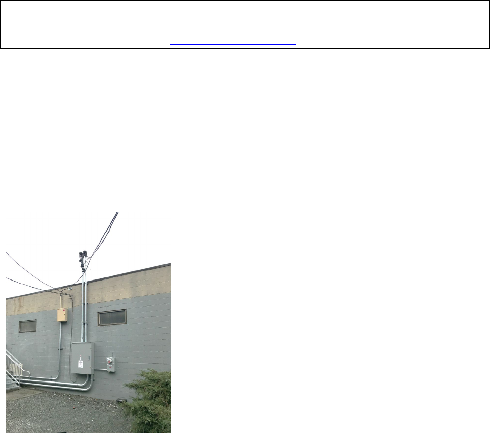
CITY LIGHT REQUIREMENTS FOR ELECTRIC SERVICE CONNECTION 2024 EDITION | PAGE 43
Please see the appendix document, “Contractor’s Pre-Installation Checklist Multi-Unit Metering,” for more
information.
For information on meter height, working space, and clearances for equipment (meter) rooms, see City
Light Construction Standard 1554.42, Meter Height, Dedicated Equipment Space, Working Space, and
Clearances, Equipment Rooms in the Standards for Electric Service.
6.9. Current Transformers
6.9.1. Current Transformer-Rated Metering
Current transformers (CTs) and/or voltage transformers are required on all services that exceed 225 A. See
Figure 6.9.1 for a typical CT service.
Exceptions: (1) residential services with 400 A services that use class 320 metering, and (2)
remote metering with services under 225 A.
Figure 6.9.1. CT Service, Typical
A
ll transformer
-r
ated meter sockets must have test switch provisions.
6.9.2. Landing Pads and Enclosures
Current transformer enclosures must contain only service conductors, metering equipment, and meter
conductors. They must not be used as a junction box, gutter, or raceway for the purpose of making taps.
Line-side taps are not allowed.
Exception: Taps must be allowed on the load side of the customer’s landing pads to
accommodate emergency services, fire pumps, and/or elevator ventilation systems as allowed by
local/national fire codes.
CITY LIGHT REQUIREMENTS FOR ELECTRIC SERVICE CONNECTION 2024 EDITION | PAGE 44
All services rated at 800 A or less that use current transformer landing pads having mechanical lug
provisions for termination of line and load conductors. Landing pads must be centrally mounted in the
current transformer enclosure and the conductors will enter and leave near the corners.
Note: If terminations cannot be made in accordance with manufacturer requirements and/or
equipment listing, a bus gutter will be required to accommodate additional taps.
The minimum size of current transformer enclosures must be as follows:
• Single-phase 400 A or under: 24 inches wide x 48 inches high x 11 inches deep
• Single-phase over 400 A: 36 inches wide x 48 inches high x 11 inches deep
• Three-phase: 36 inches wide x 48 inches high x 11 inches deep
Note: Larger current transformer enclosures may be necessary depending on the National Electric
Code (NEC) requirements for conductor bends.
All landing pads must be of heavy-duty type with minimum (AIC) fault duty rating of 50,000 A rms
symmetrical. They must be UL labeled.
The cover of the current transformer enclosure or switchgear must be side-hinged and have provisions for
locks and seals. Hinges must be built so that they cannot be disassembled from the outside of the
enclosure.
The top of the current transformer enclosure must not be higher than 7 feet and the bottom must not be
lower than 6 inches from the finished grade or floor.
Connection to the grounded service conductor (neutral) must not be used to bond current transformer
enclosures. Bonding must be derived from the service main grounding point.
CITY LIGHT REQUIREMENTS FOR ELECTRIC SERVICE CONNECTION 2024 EDITION | PAGE 45
6.9.3. Secondary Wiring
The customer must provide a 1-inch minimum conduit between the current transformer enclosure and the
meter socket. A maximum of 360 degrees of bends is allowable. For metering runs over 75 feet, a
1-1/4-inch minimum conduit is required.
Junction boxes and condulets are not allowed in conduit runs for secondary metering conductors.
The customer must provide metering secondary conductors, leaving 8 feet of wire in the current
transformer enclosure and 2 feet of wire in the socket enclosure.
Exception: City Light will provide the metering secondary conductors when the socket is within
10 feet of the current transformer enclosure.
All secondary conduit runs over 75 feet must have prior approval by the City Light Technical Metering
Unit. Conduit runs beyond 250 feet are not permitted.
The conductor colors for CT metering secondary runs are as follows:
• Single-phase: 1 black, 1 red, #12 solid conductor (voltage)
• 1 black, 1 red and 1 white #10 solid conductor (current)
• 1 green #12 solid conductor (bonding)
• Three-phase: 1 black. 1 red, 1 blue, 1 white, #12 solid conductor (voltage)
• 1 black, 1 red, 1 blue, 1 white #10 solid conductor (current)
• 1 green #12 solid conductor (bonding)
For secondary runs over 75 feet the current conductors need to be sized as follows:
• #8 stranded conductors for current circuits from 75 feet to 150 feet
• #6 stranded conductors for current circuits from 150 feet to 250 feet
6.10. Switchgear
6.10.1. General
City Light’s Technical Metering Unit will provide the customer with specific information on metering
requirements for individual projects after they have reviewed plans submitted by the customer. Prints or
drawings of the metering equipment must be submitted and approved by City Light prior to manufacture
when the equipment is to be installed in switchgear. The drawings need to show the sequence of
compartments, dimensions of the gear and manufacturer information.

CITY LIGHT REQUIREMENTS FOR ELECTRIC SERVICE CONNECTION 2024 EDITION | PAGE 46
6.10.2. Switchgear Operating at Voltages Up to and Including 480 V
M
ultiple self
-c
ontained metering: the clear space around each meter socket will not be less than 1 inch at
the top and the sides, and not less than 2 inches at the bottom.
All clearances must meet requirements specified in City Light Construction Standard 1554.42, Meter Height,
Dedicated Equipment Space, Working Space, and Clearances, Equipment Rooms in the
Standards for Electric
Service.
The termination cabinet, current transformer cabinet, and any other switchgear section exclusively under
City Light’s control must not contain any customer equipment that requires servicing, control wiring or
load monitoring equipment. These sections must contain only service entrance conductors/bus and City
Light metering equipment. For further information contact your City Light Representative.
Permanent switchboard metered services must not have the electric meter located on the switchboard
door adjacent to the current transformer compartment. The meter must be located in a remote single
meter socket with a test switch provision on the nearest possible wall.
Note: Permanent engraved phenolic unit or equipment designation labeling is required at both the
meter socket and the switchboard.
6.10.3. Switchgear Operating at Voltages Greater Than 480 V
Contact your City Light Representative for requirements and construction guidelines.
6.11. Master Metering
City Light will not supply electricity for any new service to a duplex or multiple dwelling building for the
purpose of master metering the energy usage of the dwelling units, a central space heating system, or a
central domestic water heating system, per Seattle Municipal Code 21.49.100
. City Light will not supply
electricity for any upgraded service to an existing duplex or multi-unit building for the purpose of master
metering new central or individual space heating systems.
An owner-occupied dwelling unit also containing an additional “accessory housing unit” meeting all
provisions as defined in Seattle Municipal Code 23.44
and approved by the City of Seattle will be allowed
to master meter.
Master metering is required for boat moorages but prohibited for houseboats.
6.12. Advanced Metering Infrastructure (AMI) for Meter Rooms
W
here meter rooms are vertically stacked, a 2
-in
ch Schedule 40 PVC conduit pathway connecting all of
the meter rooms must be provided for the Advanced Metering antenna cable. Lateral meter rooms should
also be tied into the vertical distribution stack whenever possible.
The conduit must have a maximum of 360 degrees in total bends.
A
1/8
-in
ch minimum nylon zip tie pull string is to be provided in the conduit.

CITY LIGHT REQUIREMENTS FOR ELECTRIC SERVICE CONNECTION 2024 EDITION | PAGE 47
All connection cables for Advanced Meters will be provided by City Light and installed by the customer.
City Light will make all connections.
Cables must be in contiguous runs, without splices, unless otherwise approved by City Light.
In
either the top-most or bottom-most meter room (including sub-grade meter rooms), provide a 2
-i
nch
Schedule 40 PVC conduit to a NEMA 3R enclosure (enclosure must be at least 8 in x 8 in x 6 in) mounted
on exterior of the building. The conduit must have a maximum of 360 degrees in total bends and be no
more than 100 feet of total length.
A
1/8
-in
ch minimum nylon zip tie pull string is to be provided in the conduit.
N
EMA 3R enclosure must be mounted in a location that is approved by City Light and is safe to access.
NEMA 3R enclosure must be mounted between 14 and 20 feet above ground level unless roof top access
is available and can be accessed without hazard/restraint.
Cables must be in contiguous runs, without splices, unless otherwise approved by City Light.
In the meter room with conduit to the exterior of building, the customer must provide a
2 ft x 2 ft x 3/4-inch plywood mounting board with dedicated duplex receptacle:
• Plywood must be mounted on wall adjacent to meter (or meter bank) less than
20 linear feet from closest meter.
• The bottom edge of the plywood mounting board must be between 4 and 6 feet
above floor level.
• A dedicated 120 V, 15 A duplex power receptacle must be located below the plywood
mounting board.
6.13. Communications Provisions for Large Metered Loads
New or enlarged commercial/industrial services served by a single meter with loads that are expected to
reach 1 megawatt or more, or that will be totalized, are required to have a phone line or communication
line that meets City Light requirements at the point of metering. The customer must own, install, and
maintain the phone/communication line.
Totalizing is permitted per Seattle Municipal Code 21.49.010
. For more information, contact your City
Light Representative.
Where totalized metering is permitted, the customer must install the totalizing circuitry. Meter totalizing
must meet the Utility’s criteria and be approved by City Light before metering equipment will be installed
CITY LIGHT REQUIREMENTS FOR ELECTRIC SERVICE CONNECTION 2024 EDITION | PAGE 48
6.14. Temporary Totalized Metering
At City Light's discretion, Temporary Totalized Metering may be utilized to capture a customer’s total
consumption for billing purposes. This temporary metering will generally apply to a project during initial
construction but may be used when a customer is altering or upgrading their service entrance equipment.
All required equipment for this metering will be the sole responsibility of City Light, and all metered
consumption will be billed in accordance with the appropriate rate schedule.
If a customer completes a Temporary Totalized Metering Agreement Form with the assistance of the
appropriate City Light Representative, they will be allowed to shunt self-contained meter sockets prior to
installation of the permanent metering.
Once the facility is ready for permanent meter installation, it is the responsibility of the property owner to
contact City Light and ensure that all metering facilities are prepared according to City Light
specifications, including the Multi-Unit Pre-metering Checklist. Failure to meet these requirements may
result in fines, additional trip charges, and installation delays.
Communication Provisions for Large Metered Loads are in no way altered or impacted by the
requirements of the Temporary Totalized Meter specifications.
6.15. Net Metering
City Light allows net metering on approved customer generation installations of up to 100 kW AC in most
areas of the service territory. For more information, see Chapter 5, Distributed Energy Resources.

CITY LIGHT REQUIREMENTS FOR ELECTRIC SERVICE CONNECTION 2024 EDITION | PAGE 49
7. Motors and Special Loads
7.1. Introduction
Some of City Light’s large commercial or industrial customers may require motors or special loads. This
chapter identifies the City Light requirements related to motors and special loads.
All motor equipment must conform to the standards of the National Electrical Manufacturers Association
(NEMA).
City Light requires detailed information about new motor load installations.
At time of application for service, the customer must provide suitable protective devices on all motor
installations, including protection against single phasing on polyphase motors.
7.2. Motor-Starting Limits and Interference
The customer’s use of electricity must not interfere with the quality of their own service and must not
interfere with the quality of service to other customers. If any motor and associated device(s) cause
interference with its owner’s or another customer’s electrical service, the owner of the motor/device is
responsible for taking corrective action at their own expense. Conforming to the requirements does not
assure that interference problems will not occur.
Interference problems may arise when:
• The customer needs voltage control within unusually close tolerances
• There is an unbalance of single-phase and three-phase loads
• Where the customer intermittently switches large loads on and off, such as electric
boilers, heaters, or motors
7.3. Voltage Flicker
Voltage flicker is defined as the subjective impression of fluctuating luminance caused by voltage
fluctuations. It is caused by momentary motor starting currents, switching currents, or by fault current of
the distribution system.
The customer is required to adhere to City Light-established voltage flicker limits.
For more information, see City Light Construction Standard 0041.05, Voltage Flicker Limits in the
Standards
for Electric Service.
CITY LIGHT REQUIREMENTS FOR ELECTRIC SERVICE CONNECTION 2024 EDITION | PAGE 50
7.4. Starting Limitations on Single-Phase Motors
O
ne
-ha
lf horsepower or larger motors on recurrent starting with more than one start per hour, such as
those operating water pumps or furnace blowers, must be served at not less than 240 V (208 V in the
Network system). Single
-p
hase motors must not exceed the maximum locked rotor currents listed in
tables 7.4a and 7.4b, unless approved in writing by City Light.
TABLE 7.4a. SINGLE-PHASE MOTOR MAXIMUM ALLOWABLE LOCKED ROTOR CURRENTS
Rated Size (hp)
At 208 V
At 240 V
5
149 A
129 A
TABLE 7.4b. SINGLE-PHASE HERMETIC REFRIGERANT MOTOR COMPRESSOR MAXIMUM
ALLOWABLE LOCLED ROTOR CURRENTS (FROM NEMA STANDARDS)
Rated Size (hp)
Motor Size (hp)
208 V (Network Only)
240 V
5
5
200 A
173 A
7.5. Starting Limitations on Polyphase Motors for Secondary Services
Across-the-line starting of 15-horsepower motors or less will be permitted for starting currents less than
values in Table 7.5. Reduced starting current devices must be required on all motors exceeding a 15 hp
nameplate rating, or motors started more frequently than one start per hour.
Up
on failure to install the required starting device, City Light will disconnect the service until it is
acceptable. Reconnection must be at the customer’s expense.
TABLE 7.5. POLYPHASE MOTOR MAXIMUM ALLOWABLE LOCKED ROTOR CURRENT (DERIVED
FROM NEMA STANDARDS)
Rated Size (hp)
120/208Y,
Three-Phase (A)
120/240,
Three-Phase (A)
277/480Y,
Three-Phase (A)
240/480
Open Delta (A)
15
250
125
108
63
Note: Starting devices may be omitted on smaller motors of a group installation when the omission does not result in a
starting current in excess of the starting current limits shown.
7.6. Electric Power Regeneration Due to Motor Drive/Control
R
egeneration of electric power while braking, or upon motoring
-d
own, must not exceed circuit loading at
the common point of termination unless the operation has been approved by City Light. Typically,
regeneration is intermittent and can cause mis-operation of the distribution system which may jeopardize
worker safety.
CITY LIGHT REQUIREMENTS FOR ELECTRIC SERVICE CONNECTION 2024 EDITION | PAGE 51
7.7. Maximum Switched Load
The maximum increment of load to be switched as a unit will be 90 kVA, three-phase or 30 kVA, single-
phase. Loads in excess of these amounts may require the customer to furnish and install special switching
equipment to reduce the magnitude of unit loads to be cycled on and off.
7.8. Welding Equipment
Welding equipment must conform to the standard of the National Electrical Manufacturers Association
(NEMA).
7.9. Minimum Power-Factor Limitations
7.9.1. Lighting
Low power-factor lighting, such as LED, neon, mercury vapor, and fluorescent, must have suitable auxiliary
equipment to provide a power factor of not less than 97% lagging at the meter location.
7.9.2. 85% Minimum Power Factor
The minimum power factor per billing cycle must be at least 97% lagging and always above 85% lagging
at the meter location. Any auxiliary power factor correction equipment must be switched with the load so
that at no time will it supply leading Volt Ampere Reactive (VAR) to the City Light distribution system
unless there is written approval by City Light.
7.9.3. Capacitor Control
Capacitors installed by the customer for power-factor correction must be switched by automatic means so
that the capacitors will be switched off during periods of reduced load.
CITY LIGHT REQUIREMENTS FOR ELECTRIC SERVICE CONNECTION 2024 EDITION | PAGE 52
8. Emergency Backup: Generators and Energy
Storage Systems
8.1. Introduction
Emergency backup equipment may be either fossil-fuel-based generators, or energy storage systems
(such as a battery system), which would be used to supply electricity to a customer or customers
during a power outage. Such equipment must be configured to never operate in parallel with the
City Light electrical grid.
If energy storage systems are configured so they may operate in parallel to the City Light electrical
grid, this chapter is not pertinent. Instead, they will be considered Distributed Energy Resources and
must file an interconnection application with City Light. See Chapter 5 for information on City Light’s
interconnection requirements. Most battery storage systems, whether in hybrid designs with solar or
in standalone designs, are configured to operate in parallel, even if their main purpose for customers
is power supply during grid outages.
Emergency backup systems must comply with all applicable NEC codes, such as NEC Article 445 for
Generators, NEC Article 700 for Emergency Systems, NEC Article 701 for Legally Required Standby
Systems, and NEC Article 702 for Optional Standby systems.
8.2. Inverter-Based Emergency Backup Systems
All inverter-based emergency backup systems must have batteries as their energy source.
8.3. Transfer Switches
All emergency backup generators and energy storage systems must have a transfer switch that
prevents the interconnection of the emergency backup generator or energy storage system with the
City Light electrical grid.
Transfer switches must be the “open transition” type.
Specifications and drawings of the open transition switch must be submitted to City Light as part of
the application process for electric service connection.
CITY LIGHT REQUIREMENTS FOR ELECTRIC SERVICE CONNECTION 2024 EDITION | PAGE 53
9. Maintenance of Equipment and Facilities
9.1. Introduction
This chapter describes the division of responsibility between City Light and the customer for the
maintenance of equipment. Table 9.1 shows distribution of responsibility by category.
TABLE 9.1. DISTRIBUTION OF RESPONSIBILITY FOR MAINTENANCE OF EQUIPMENT
AND FACILITIES
Customer
• All masts, brackets, conduits, and other service entrance equipment
• Installation of conduit and trenching to the City Light-designated point of connection to the system
• Equipment on the load side of the meter
• Any other equipment for which the customer is assigned responsibility in written agreements between
City Light and the customer
• Vegetation to ensure a 3-ft radius of space for overhead conductors from the service pole to the
weatherhead; if there is a transformer on the service pole, the customer is not responsible for any
vegetation in a 4-ft area around the transformer
• Underground services, as follows:
o Services in conduit: City Light will provide new service wire if the existing conductors fail. The
City Light crew will pull out the old wire and install new service wire provided they are able to
remove the old conductors.
Note: If the conduit has been damaged or rusted, the wires may not be able to be removed.
The customer will be responsible for replacing the conduit run.
o Services without conduit: In situations where the service wire is buried in the ground without
conduit (“Direct bury”) and the service fails, City Light will locate the fault, excavate, repair the
cable, and backfill the excavated material. The customer is responsible for all surface
restoration, e.g., grass, shrubbery, concrete.
Note: Only one repair will be attempted per service drop. If additional faults occur, the customer will be
responsible for replacing the failed service with a service in conduit that meets City Light standards.
City Light
•
All vegetation pole-to-pole
• All City Light-installed poles and anchors
• Customer-owned poles installed by City Light — this maintenance will be at the customer’s expense
• All meters, instrument transformers, and related equipment; see Chapter 6, Metering
CITY LIGHT REQUIREMENTS FOR ELECTRIC SERVICE CONNECTION 2024 EDITION | PAGE 54
9.2. Charges
There will be no charges for installing underground service conductors on existing services for
replacement due to failure. Except where the conductors have faulted as a result of some action on the
customer’s part, e.g., wire damaged by digging; post or retaining wall installation damaging conduit and
wire; improper backfill. If the cause of the fault is related to such or other actions, the customer will be
charged for the repair work.
9.3. Temporary Restoration of Service
City Light may restore service on a temporary basis until the customer completes the necessary work so
City Light can replace the service conductors. If City Light is unable to install an electrical meter during this
time, the customer will receive an estimated bill for the period their electrical usage is unmetered.
The temporary service will be granted for a maximum of two (2) weeks.
CITY LIGHT REQUIREMENTS FOR ELECTRIC SERVICE CONNECTION 2024 EDITION | PAGE 55
Glossary
ACCESSORY DWELLING UNIT (ADU): A separate living space within a house or on the same property as
an existing house. These units are not legal unless they have been established through a permit process. A
legally permitted unit in the home is called an attached accessory dwelling unit (AADU). A legally
permitted unit on the property (but not within the home) is called a detached accessory dwelling unit
(DADU) or backyard cottage. Tiny houses, with foundations, are considered DADUs.
AMPERES: The base unit of electric current.
AMPACITY: Current-carrying capacity measured in amperes.
ASSOCIATED EQUIPMENT: In discussions of metering equipment, the term includes the meter socket,
instrument enclosures, test switches, and other equipment.
AUTHORITY HAVING JURISDICTION: Refers to the local jurisdiction which permits and inspects
electrical services. In the City of Seattle, this is the Department of Planning and Development (DPD).
BALANCED: When loads or phase currents on a three-phase circuit are equal.
BRIDLED SERVICE: An overhead service wire originating from one Utility pole that uses a guy wire from
an adjacent pole to change the route of the service drop to the service entrance attachment point.
BUS (BAR): Flat metallic conductor housed within switchgear or an enclosure.
CABINET: An enclosure designed for surface or flush mounting and provided with a frame, mat or trim,
and swinging doors. Cabinets are usually employed to contain panel boards.
CONNECTION: A one-way electric service connection between the utility and the customer. See
Interconnection.
CONDUCTOR: A material that allows electricity to move through it easily. A wire, cable, bar, rod, or tube
that serves as a path for electricity to flow. The most common conductor used by City Light is overhead
wire.
CONDUIT: A UL-labeled wireway with a smooth interior surface that permits easy drawing in of the
electrical conductors.
CURRENT: The electrical current is simply a measure of how much electricity passes a given point in a
fixed amount of time. It is measured in amperes.
CURRENT TRANSFORMER (CT): A transformer used in instrumentation to assist in measuring current.
CUSTOMER: Any person, firm, corporation, government agency, or other entity that uses, has used, or has
contracted for electric service from City Light.
DEMAND: The amount of electricity drawn from an electrical system at a given time, measured in kW’s;
the amount of power required to meet the customer’s load at a given instant or averaged over any
designated interval of time, expressed in kilowatts or megawatts.

CITY LIGHT REQUIREMENTS FOR ELECTRIC SERVICE CONNECTION 2024 EDITION | PAGE 56
DIRECT BURY: The installation of electric conductors in a trench without the use of a conduit. Direct
burial installations are no longer accepted by City Light.
DRIP LOOP: A downward loop in the customer’s conductors, near where the customer’s conductors
attach to the Utility’s overhead conductors, to prevent water from entering the service at the
weatherhead.
EASEMENT: See Service Easement.
ELECTRIC SERVICE: All service conductors (primary and secondary), transformers, and distribution system
equipment for delivering electric energy from City Light’s supply system to the wiring system of the
premises.
FAULT CURRENT: A current that flows between conductors or between a conductor and a ground
because of an abnormal connection between the two.
GENERAL SERVICE: Any service that is not residential, as defined by the Seattle Municipal Code
.
GROUND ROD: An approved metal rod or pipe placed in the ground to which electric connection can be
made in order to maintain earth potential on equipment.
GROUP INSTALLATION: An installation that includes more than one electrical device, such as panels,
meters, motors, etc., connected together by a common electric circuit.
GUTTER: See Wiring Gutter.
GUYING FACILITY: Cables or braces used to relieve stress on masts and poles.
HANDHOLE: A permanently installed protective enclosure (usually below grade), which is used for
gaining access to electrical conductors for the purpose of pulling, splicing, or terminating.
HERTZ (Hz): A unit of frequency equal to one cycle per second; refers to the frequency of alternating
current (ac).
HI
GH LEG: In a four
-w
ire Delta service, the phase leg that is at higher potential/voltage to ground than
the other two
-p
hase legs. Also called the wild leg or the delta leg.
INSTRUMENT TRANSFORMER: Current and/or voltage transformers used in connection with metering
and control devices.
INTERCONNECTION: A type of electric service connection in which the customer has installed a
Distributed Energy Resource and has entered into an Interconnection Agreement with City Light. See
Ch. 5, Distributed Energy Resources.
INTERCONNECTION FACILITY: Electrical wires, switches, metering, and other equipment owned by City
Light or the customer and used to interconnect a DER to the electrical grid. Interconnection facilities are
located between the DER and the point of termination. These facilities do not include system upgrades.
INVERTER: An electronic device used to change dc current into ac current.
CITY LIGHT REQUIREMENTS FOR ELECTRIC SERVICE CONNECTION 2024 EDITION | PAGE 57
INVERTER-BASED RESOURCE: A DER that relies on one or more power electronic devices that convert
direct current power to alternating current power by means of electronic switching. These resources
include, but are not limited to, solar photovoltaic systems and battery energy storage systems.
JUNCTION BOX: A box, which may be metallic or non-metallic, that has openings in the sides and back
and is used to protect and support electrical wire connections or conductor splices.
KCMIL: One thousand circular mils; a measurement of wire size.
KEYBOX: A permanently installed lock box with keys enclosed. Keyboxes allow City Light personnel to
gain access to a customer’s premises for the purpose of reading, installing, servicing, or removing City
Light system components.
KILOWATT (kW): One thousand watts; a standard measure of demand for power or capacity.
KILOWATT HOUR (kWh): The standard unit of measure for electric energy. One kilowatt-hour is one
kilowatt of electricity supplied for one hour.
KILOVOLT AMPERE (kVA): A rating that designates the output which a transformer can deliver at rated
voltage and frequency without exceeding a specified temperature rise.
LANDING PADS: Hardware upon which current transformers are mounted in the CT can.
LOCKED ROTOR CURRENT: Steady-state current drawn by a motor with the rated voltage and frequency
applied and the rotor locked in a stationary position. This is the maximum current the motor will draw.
MANDREL: A tapered, or cylindrical, spindle inserted into, and pulled through the distance of, the
installed conduit run for clearing the conduit run of foreign material.
MASTER METER: Any single meter that measures the electrical consumption of all units or subdivisions of
a building.
MACHINE-BASED GENERATION RESOURCE: A generator that converts mechanical energy into electrical
energy. This resource category includes, but is not limited to, synchronous and asynchronous generators.
Typical fossil fuel turbine- or reciprocating engine-based generation systems are examples of
synchronous generators. Typical wind turbine and run-of-the-river hydropower systems are examples of
asynchronous generators.
METER SOCKET: A receptacle for the installation of an electric meter.
METER TOTALIZING: See Totalized Metering.
METERING EQUIPMENT: Any equipment used to measure electrical energy.
MICROGRID: A group of interconnected loads and DERs within clearly defined electrical boundaries that
acts as a single controllable entity with respect to the electrical grid.
MOTOR STARTING LIMITATIONS: Limits placed by City Light on maximum starting current of electric
motors.
MULTIPLE DWELLING BUILDING: Any building or any portion of the building which contains three or
more dwelling units, occupied with provisions for living, sleeping, cooking, and sanitation.
CITY LIGHT REQUIREMENTS FOR ELECTRIC SERVICE CONNECTION 2024 EDITION | PAGE 58
NAMEPLATE CAPACITY (DER-related): The rated capacity of a DER measured in AC. For an inverter-
based DER, nameplate capacity is the combined rated capacity in AC of the inverter(s) that are part of the
DER.
NEC: National Electric Code.
NEMA: The National Electrical Manufacturers Association.
NET METERING: A method of crediting customers for electricity that they generate on site in excess of
their own electricity consumption.
NETWORK SERVICE AREAS: Network service areas are designed to provide redundancy and continuity of
service in the case of outages and include protective devices to prevent backfeed onto the grid. Network
service areas exist in Downtown Seattle, First Hill, South Lake Union, and parts of the University District.
NEUTRAL: The grounded conductor of a single-phase, 3-wire or 3-phase, 4-wire system. The identified
conductor that is at zero potential/voltage to ground.
NON-INDUCTIVE LOAD: An electrical load consisting entirely of resistance.
OPERATE / OPERATING IN PARALLEL: The synchronous operation of a Distributed Energy Resource
(DER) while interconnected with the City Light electrical grid.
OVERCURRENT: An overcurrent is a current exceeding the rated current. An overcurrent can be due to
overloading a circuit, a fault, or a short circuit.
OXIDE INHIBITOR: A compound used to retard oxidation on electrical connections where aluminum
conductors are used.
PEDESTAL: A free-standing structure used exclusively to support or contain electrical metering equipment
and/or customer service equipment.
POINT OF ATTACHMENT: The point at which City Light’s service conductors are attached to a structure
by an approved service bracket.
POWER FACTOR: The ratio of true power (kilowatts) to the apparent power (kilovolt-amperes) for any
given load and time.
PRIMARY SERVICE: Any service that exceeds the maximum secondary service capacity shown in Table
3.3. These services require transformers or primary metering enclosures to be located in vaults or on pads
located on the customer’s property.
PRIVATE PROPERTY: Land owned in fee-simple title by an individual, individuals, or corporations.
PUBLIC RIGHT-OF-WAY: Land set aside and designated for use by the public for common access and
City Light functions, such as streets, alleys, boulevards, and walkways.
RACEWAY: An enclosed channel for holding wires or cables.

CITY LIGHT REQUIREMENTS FOR ELECTRIC SERVICE CONNECTION 2024 EDITION | PAGE 59
RECLOSER: A complex form of circuit breaker which protects electrical systems from temporary voltage
surges and other unfavorable conditions. In addition to preventing electrical overloads from passing
through a circuit, reclosers can automatically “reclose” the circuit and restore normal power transmission
once the problem is cleared.
RES
IDENCE: A single
-f
amily dwelling.
S
ECONDARY SERVICE: Services where the load is served from transformers in the right-of-way or
easement areas that meet the requirements defined in Table 3.3.
SERVICE BRACKET: Approved insulators installed by the customer to provide a mechanical termination
for the overhead service wires from the City Light distribution system to the customer’s structure.
SERVICE CONDUCTORS: Extend from the City Light distribution system to the point of service connection
at the customer’s property or facility.
SERVICE EASEMENT: A right acquired by City Light to construct, operate, maintain, reconstruct, and alter
overhead or underground electric facilities on private property, including property owned by another
public agency.
SEAL: A locking device to secure a meter or other service equipment.
SERVICE ENTRANCE CAPACITY: The rating in amperes of the customer’s service equipment.
SERVICE ENTRANCE EQUIPMENT: Service conduit, conductors, weatherhead, meter socket, and load
center.
SERVICE MAST: For overhead service, the conduit above the meter used to provide mechanical
protection for the customer’s service conductors, and to support the service drop from the City Light
distribution system.
SERVICE POLE: A pole necessary to provide adequate clearance and support of the service drop.
SERVICE RATING: The size (in amperes) of the service entrance equipment.
SERVICE STRIKE: The overhead point of attachment for City Light’s service drop to be attached to the
customer’s conductors.
SERVICE STUB: An underground conduit to be used in the future to pull conductors to the customer’s
property.
SHORT PLAT: A short subdivision; a division of land into two to nine lots. See
Seattle Municipal Code
23.24.
SPACE CHECK: In new construction, a field check is performed by City Light to verify that the metering
designations assigned by the contractor are correct as to which unit each meter is serving.
SPOT NETWORK: A spot network is a network service composed of three or four primary circuits in a
vault that are connected together on the secondary side of the transformers and is not interconnected
with a distributed grid outside the vault.

CITY LIGHT REQUIREMENTS FOR ELECTRIC SERVICE CONNECTION 2024 EDITION | PAGE 60
STEP-DOWN TRANSFORMER: A device that lowers voltages: the high voltage winding is connected to
the input or power source and the low voltage winding to the output or load.
SWITCHGEAR: The switches, fused switches, or circuit breakers used for disconnecting an electrical
circuit.
SYSTEM UPGRADES (DER-related): Additions, modifications, and upgrades to the electrical grid at or
beyond the point of termination necessary to interconnect the DER. System upgrades do not include
interconnection facilities.
TEMPORARY SERVICE: A customer’s service panel energized by City Light on a temporary basis for
construction purposes.
THREE-PHASE, FOUR-WIRE SERVICE: Voltage is carried through three conductors 120° out of phase
with the other two. Three
-p
hase power provides a more efficient means of supplying large electrical loads
like motors. It is used in industrial areas and in large buildings.
T
OTALIZED METERING: Totalized Metering (Adjacent or Remote) is the measurement for billing
purposes on the appropriate rate, through one meter, of the simultaneous demands and energy of a
customer. Totalizing can be permanent or temporary.
TRANSFORMER: Referring to a voltage transformer; a stationary device that increases or decreases the
voltage in an electrical system, through the use of primary and secondary coils.
T
RANSPORTATION AGREEMENT: A legal agreement that is required in cases where City Light cannot
access the in
-b
uilding vault to install and remove its transformers. The building owner assumes the
responsibility for moving the transformers.
U
NIT LOT SUBDIVISION: Subdivision of land to build townhouses, cottage housing developments, and
single-family residences where such uses are permitted. The development as a whole, i.e., the parent lot,
meets applicable development standards. As a result of the subdivision, the unit lot developments are
allowed to be non-
c
onforming to some developmental standards. See Seattle Municipal Code 23.22.062
.
UTILITY: Seattle City Light (“City Light”).
VAULT: An approved chamber for electrical equipment. Vaults must meet City Light construction
requirements.
VOLTAGE: The pressure behind the flow of electricity, measured in volts.
VOLTAGE FLICKER: The subjective impression of fluctuating luminance caused by voltage fluctuations. It
is caused by momentary motor starting currents, switching currents, or by fault current of the distribution
system.
WAC: Washington Administrative Code.
WATT: A unit of measure of electric power.
WEATHERHEAD: Rain tight conduit fitting installed on the top of the overhead service mast, where the
service drop is attached to the service entrance equipment.

CITY LIGHT REQUIREMENTS FOR ELECTRIC SERVICE CONNECTION 2024 EDITION | PAGE 61
WIRE TROUGH: A sheet metal channel/enclosure with a removable cover used to connect two electrical
cabinets or as a standalone assembly to house insulated electrical conductors.
WIRING GUTTER: A box with a removable face for electrical wires to run through. Wire gutters are used
when a single large cable serves several electrical meters. The cable entering the wiring gutter is
distributed and connected to the other services. The box is lockable and sealed by City Light.
WORKING PLATFORM: A safe, clear, unobstructed floor area with safe access to all electric equipment,
protected according to WAC 296-
24
-
75007
.
WORKING SPACE: An area free of any obstructions in front of meters, service panels, and electric
equipment for providing safe access to install, remove, or repair all electrical devices. A safe working space
must meet the requirements of the National and City Electrical Codes.
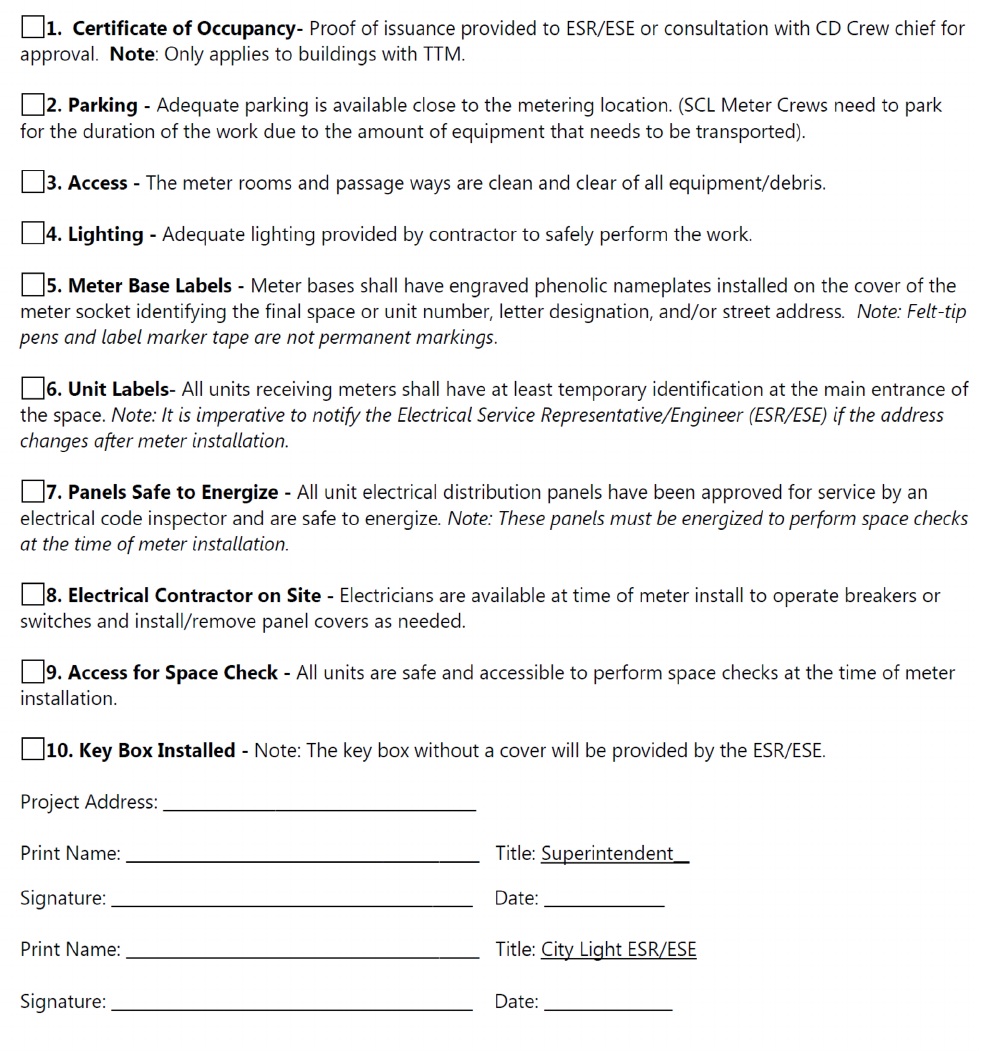
CITY LIGHT REQUIREMENTS FOR ELECTRIC SERVICE CONNECTION 2024 EDITION | PAGE 62
Appendix: Multi-Unit Metering Pre-Job Checklist
