CM2N1602en_07
2017
-05-22
Building Technologies
s
1
602
QMX3.P37 QMX3.P34 / P74 QMX3.P02 QMX3.P70 QMX3.P30 / P40
Desigo™ TRA
QMX3.P30
Q
MX3.P40
QMX3.P70
QMX3.P02
QMX3.P34
QMX3.P74
QMX3.P37
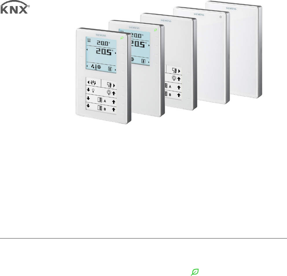
Wall-mounted sensors and room
operator units for KNX
PL-Link,
KNX S
-mode and KNX LTE-Mode
Communicative sensors, switches and room operator units with KNX (S-mode,
LTE-Mode) or KNX PL-Link (for Desigo™ Total Room Automation)
Functions (depending on type):
• Energy efficiency function ("Green Leaf
")
• Room temperature, CO
2
, and humidity measurement
• Control of light, blinds, and scenes
• PID controller for room temperature or ventilation (KNX S-mode)
• LCD Display for room temperature, operating mode, etc.
• Label for light, blinds and scenes (exchangeable, created with Word
template)
• Operation via 8 or 16 touchkeys
• Interface KNX (S-mode, LTE-Mode) and KNX PL-Link(for TRA, with plug &
play functionality)
• Powered over KNX PL-Link / KNX bus
• LEDs to indicate the switch state or the position of the device in dark rooms
2 / 16
QMX3... Wall-mounted sensors and room operator units for KNX PL-Link, KNX S-mode and KNX LTE-Mode CM2N1602en_07
Siemens Building Technologies 2017-05-22
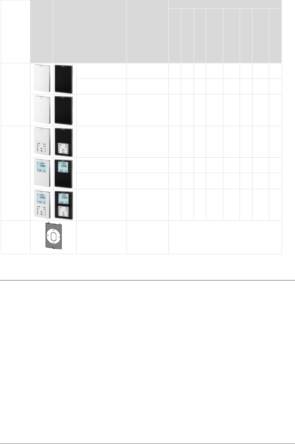
Product number Stock number Features
Temperature sensor
Humidity sensor
CO
2
sensor
Air quality indicator
with LED
Segmented backlit
display and
t hk
"Green Leaf" LED
Configurable touch-
keys with LED
di l
Window for labels
Sensors
QMX3.P30
QMX3.P30-1BSC
S55624-H103
S55624-H123
X
QMX3.P40
QMX3.P40-1BSC
S55624-H116
S55624-H124
X X
QMX3.P70
QMX3.P70-1BSC
S55624-H104
S55624-H125
X X X X
Room
operator
units
QMX3.P02
QMX3.P02-1BSC
S55624-H107
S55624-H128
X X X
QMX3.P34
QMX3.P34-1BSC
S55624-H105
S55624-H126
X
X
X
QMX3.P74
QMX3.P74-1BSC
S55624-H106
S55624-H127
X X X X X
QMX3.P37
QMX3.P37-1BSC
S55624-H108
S55624-H129
X X X X X
Accesso-
ries
QMX3.MP1
S55624-H110 Base plate for conduit box / cavity wall box for
68 mm diameter hole
20 pcs. per package
Use / compatibility
The room automation station determines the functions of both LCD display and
keys.
• Measure and indicate the room temperature, humidity and CO
2
.
• Operate the room functions.
• Indicate external information
(outdoor temp., outdoor humidity, state of a window switch).
Measure and indicate Indicate external information
− the room temperature – outdoor temperature
− the relative humidity – outdoor humidity
− the CO
2
concentration – state of a window switch
Control (threshold value switch) Control (with a PID controller)
− of the relative humidity – of the room temperature
− of the CO
2
concentration
Use with KNX PL-Link
Use with KNX S-mode
3 / 16
QMX3... Wall-mounted sensors and room operator units for KNX PL-Link, KNX S-mode and KNX LTE-Mode CM2N1602en_07
Siemens Building Technologies 2017-05-22
Switches
− switching and dimming of lights
− control of blinds
− selecting and saving of scenes
LTE can only use the sensor information of the types QMX3.P30, QMX3.P40, and
QMX3.P70.
Devices with CO
2
measurement are not suitable for safety applications such
as gas or smoke alarm.
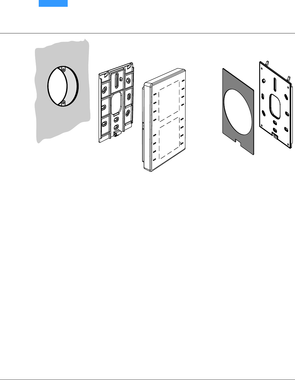
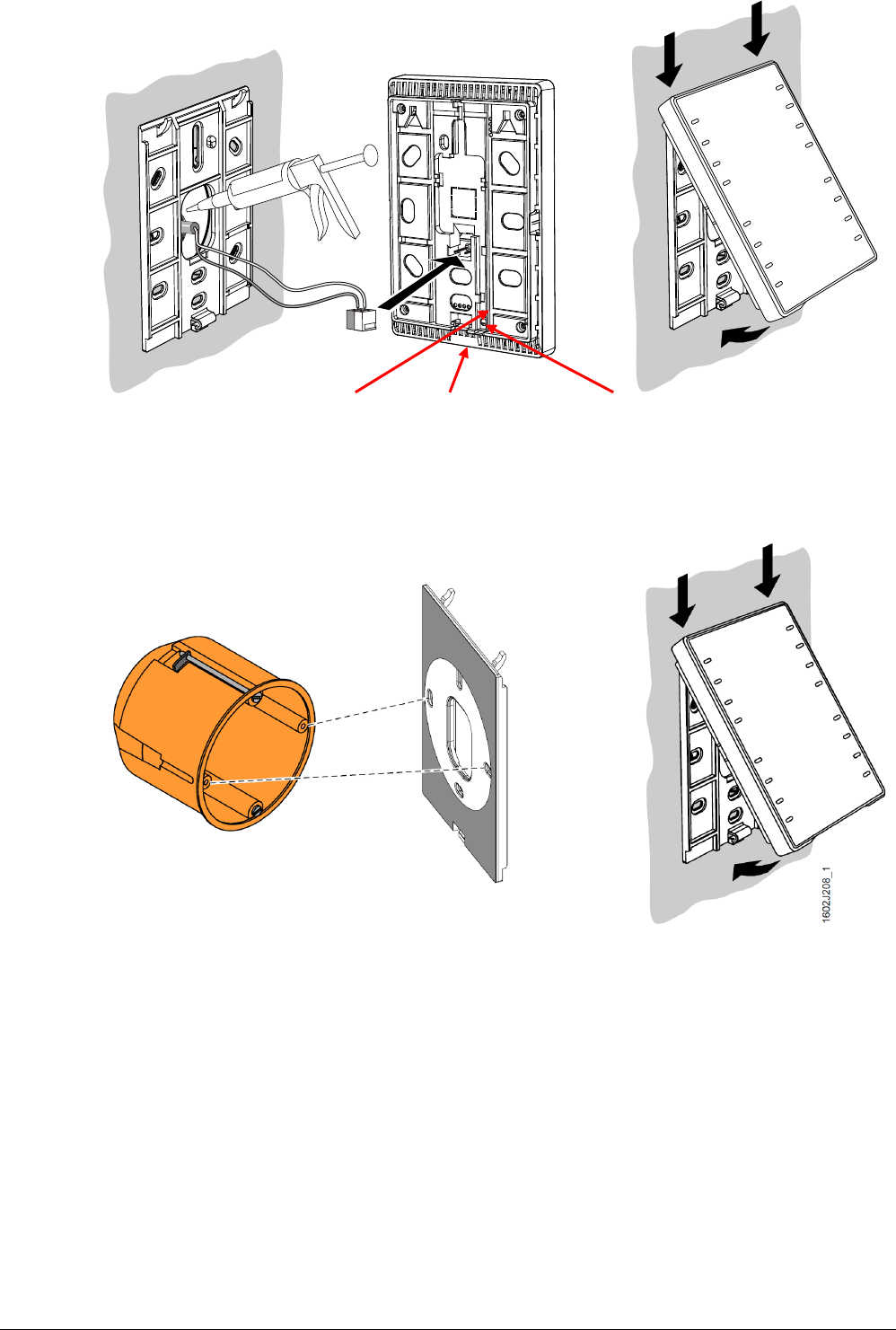
Mechanical design
• The devices are designed for wall-mounting (A). A conduit box is optional.
− Conduit box: Keep in mind the dimensions of the conduit box!
− Cable conduits on the wall: Keep a distance of 30 mm (from above) /
20 mm (from below) to the base plate (B), so that the device (C) can be
snapped onto the base plate.
• The base plate (B) has screw holes for all common flush-mount boxes.
The screw head height must not exceed 3 mm.
• The device (C) incorporates a KNX / PL-Link plug, a tool plug, and, depending
on the type, sensor element, keys, LCD panel, window for the label.
The cable can be pushed into channels on the rear.
• A KNX plug is enclosed with the devices
The optional metal-reinforced base plate QMX3.MP1 (B1) serves for two purposes:
• It is more rigid so that it does not bend when fixed in the middle with two screws
only (directly over a conduit box or a cavity wall box).
• It has a removable gray foam plate (B2) for mounting on a 68 mm diameter
cavity wall box. The plate compensates for the jutting edge of the box (see
mounting, page 5).
QMX3.MP1 is supplied in boxes with 20 pcs.
1602J01_01
B
C
A
B2
B1
Use with KNX S-mode
(continued)
Use with
KNX LTE-Mode
NOTICE
Note
4 / 16
QMX3... Wall-mounted sensors and room operator units for KNX PL-Link, KNX S-mode and KNX LTE-Mode CM2N1602en_07
Siemens Building Technologies 2017-05-22
Engineering notes
• The room operator units offer plug & play functionality.
• The room operator units receive their power from the connected room
automation station via the KNX PL-Link interface.
• KNX PL-Link supports plug & play functionality for pre-configured devices out of
the library
• For KNX PL-Link wiring (topology, allowed cables and cable length), see the
Desigo installation guide, CM111043.
• Normally, electrical installers only install the base plate and the KNX PL-Link
plug.
• Use the tear-off label with the barcode on the packaging / on the display and
stick it on the floor plan to prepare commissioning for several room operator
units per room automation station.
The same barcode label with unique identifier is available on the device.
Engineering and commissioning is done using the ETS tool
For detail information see Technical basics, P1602.
Engineering and commissioning is done using the ACS tool.
For detail information see Technical basics, P1602.
• The ABT provides a list of the devices, their function and their location
• Create the labels using a Word template (M1602.1)
• Print the labels on commercially available overhead transparency film
• Cut out the labels
• Insert or exchange the labels as described in the mounting instructions, M1602.
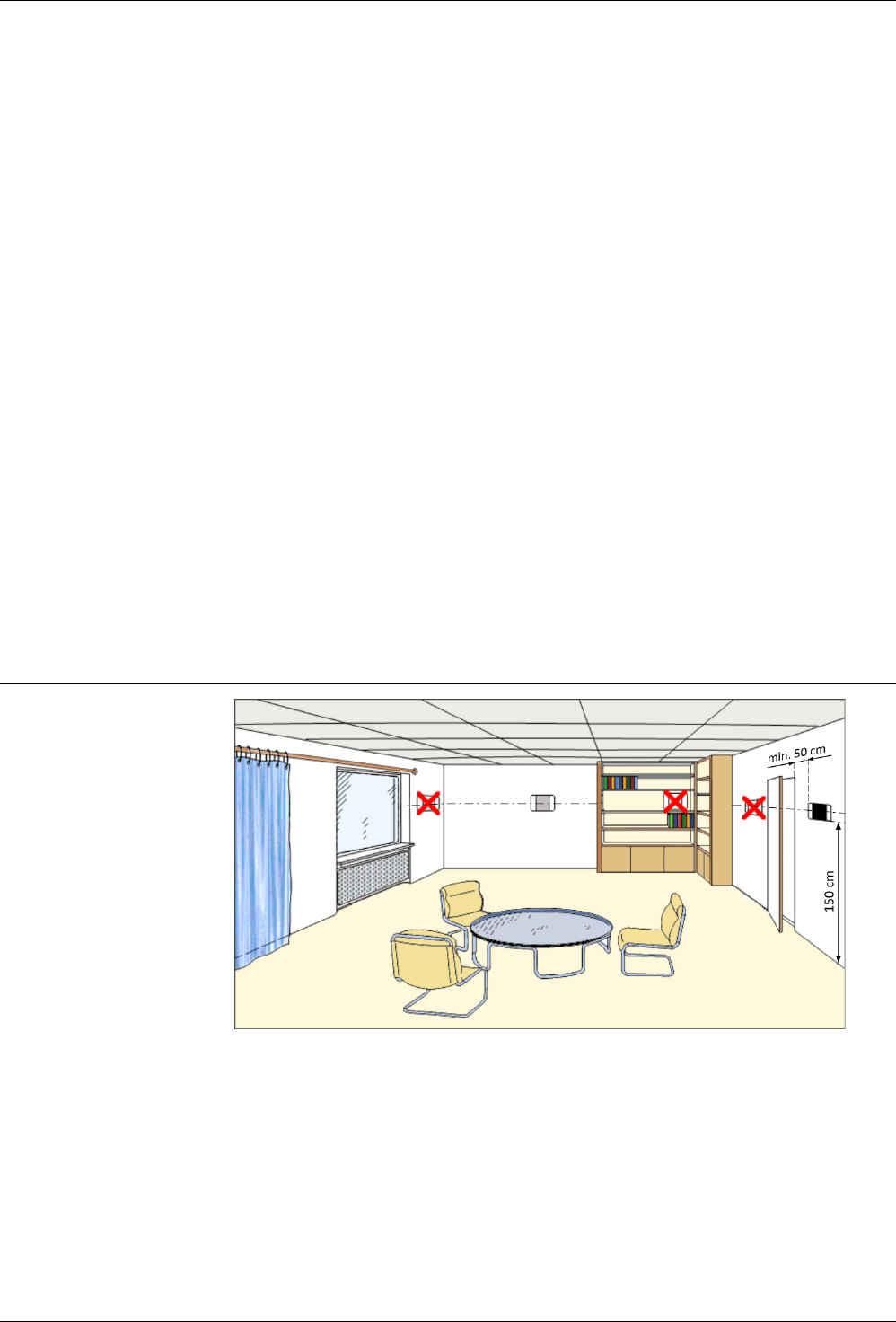
Mounting and installation
• The devices are suitable for wall mounting.
• Recommended height: 1.50 m above floor.
• Do not mount the devices in recesses, shelves, behind curtains or doors, or
above or near heat sources.
• Avoid direct solar radiation and drafts.
• Seal the conduit box or the installation tube, as air currents can affect sensor
readings.
• Adhere to allowed ambient conditions.
• Mounting instructions M1602 are enclosed with the devices.
KNX PL-Link
KNX S-mode
KNX LTE-Mode
Labels for switches
(QMX3.P02, P37)
Location (sensors,
room operator units)
Mounting instructions
5 / 16
QMX3... Wall-mounted sensors and room operator units for KNX PL-Link, KNX S-mode and KNX LTE-Mode CM2N1602en_07
Siemens Building Technologies 2017-05-22
Service LED (red) Tool plug Programming pin
*) The installing tube must be sealed or cold or warm air may enter the device and cause faulty
temperature readings by the internal sensor.
Use a metal-reinforced base plate QMX3.MP1 instead oft he standard base plate
delivered with the room operator unit.
The installing tube must be sealed or cold or warm air may enter the device and cause faulty
temperature readings by the internal sensor.
1 Fixing the box on the cavity wall.
2 Fixing the QMX3.MP1 base plate on the box using 2 screws.
3 The gray foam plate (removable) compensates for the jutting edge of the box so that the plate
is aligned with the wall.
2602J02
*
)
Mounting over a
conduit box
Monting over a cavity
wall box
1602J108
1
1
2
2
3
6 / 16
QMX3... Wall-mounted sensors and room operator units for KNX PL-Link, KNX S-mode and KNX LTE-Mode CM2N1602en_07
Siemens Building Technologies 2017-05-22
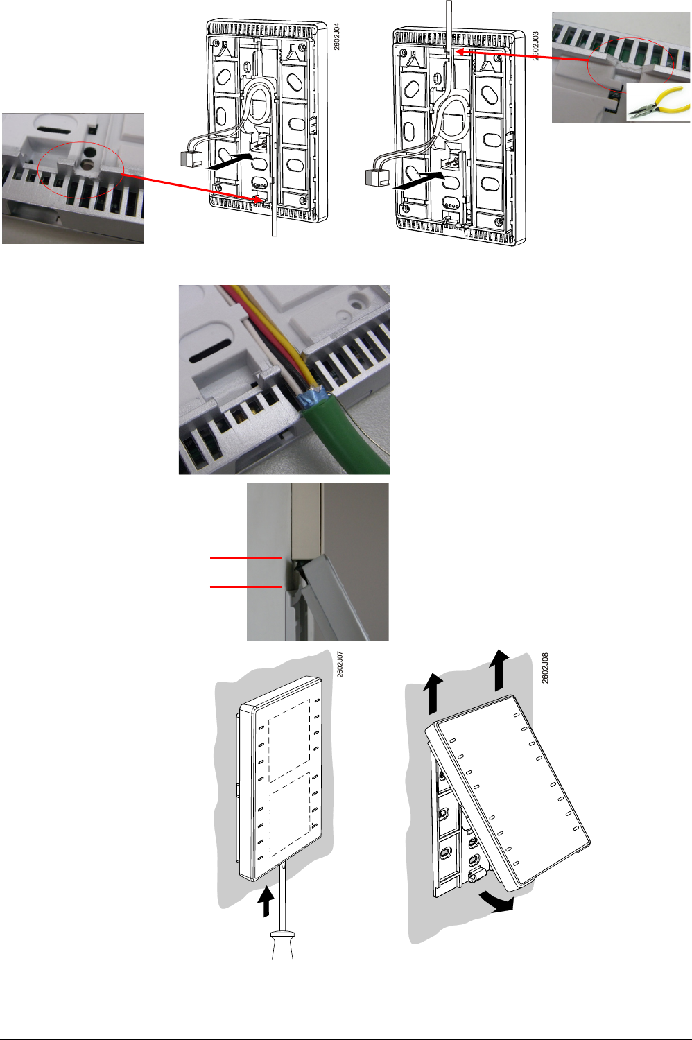
Wall mounting
Remove the breakout on the housing before putting the cable into the gaining channel.
4-wire cables
(daisy chain wiring)
Remove the cable coating, as it will not fit in
the gaining channel.
Cable ducts on the wall
30 mm
Keep a distance of 30 mm (from above) /
20 mm (from below) to the base plate,
so that the device can be snapped onto the
base plate.
Dismounting / service:
7 / 16
QMX3... Wall-mounted sensors and room operator units for KNX PL-Link, KNX S-mode and KNX LTE-Mode CM2N1602en_07
Siemens Building Technologies 2017-05-22
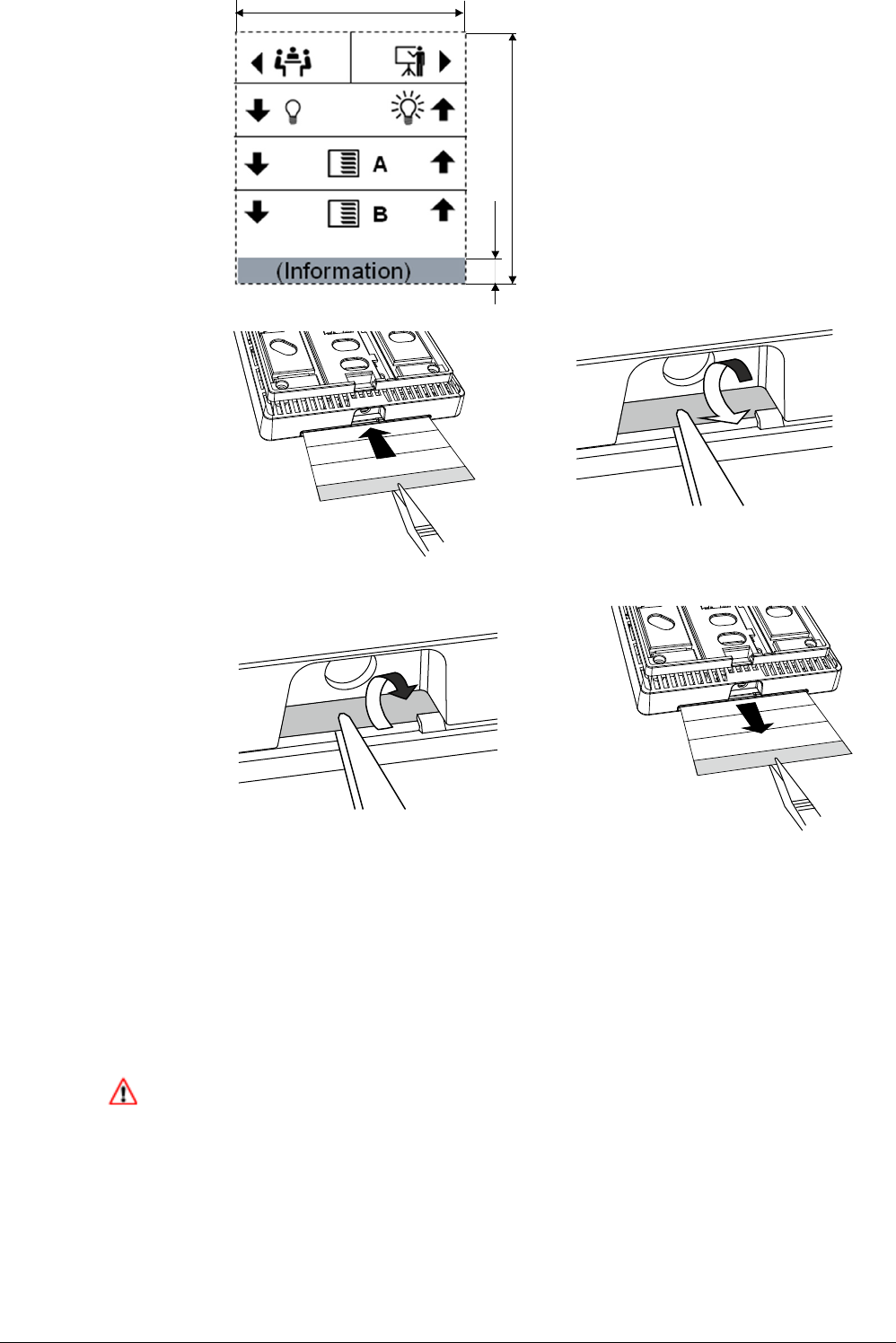
Sample icons are available in the label
template M1602.1
Information. e.g. on room operator unit
location or on room type (free text)
• For KNX PL-Link wiring (topology, allowed cables and cable length), see the
Desigo TRA installation guide, CM111043.
• Use the correct cables for the KNX PL-Link bus
• Do not interchange the wires of the KNX PL-Link cable.
– The red terminal is for KNX PL-Link +
– The gray terminal is for KNX PL-Link –
• For KNX S-mode follow the KNX regulations
• Observe all local installation regulations.
Caution!
• The devices are not protected against accidental connection to AC 230 V.
M
a
x
.
6
5
9
.2
±
0
.1
5
1
6
0
2
z
1
1
0
54 ± 0.15
Labels for QMX3.P02,
QMX3.P37
Insert label
Remove label
Installation
1602Z106
1602J109
1602J110
1602Z107
8 / 16
QMX3... Wall-mounted sensors and room operator units for KNX PL-Link, KNX S-mode and KNX LTE-Mode CM2N1602en_07
Siemens Building Technologies 2017-05-22
Prerequisite for commissioning (KNX PL-Link)
The room automation station must be running and an application must be loaded.
The application is not loaded on the room operator unit, but the room automation
station.
Download of the application is done using the SSA-DNT (Pack & Go) or the ABT.
For this purpose (or for service), connect the ABT to the room automation station
(USB or Ethernet).
Manual commissioning (KNX PL-Link)
All commissioning work is done via the room automation station, using the SSA-
DNT or the ABT.
The ABT is never connected directly to a room operator unit.
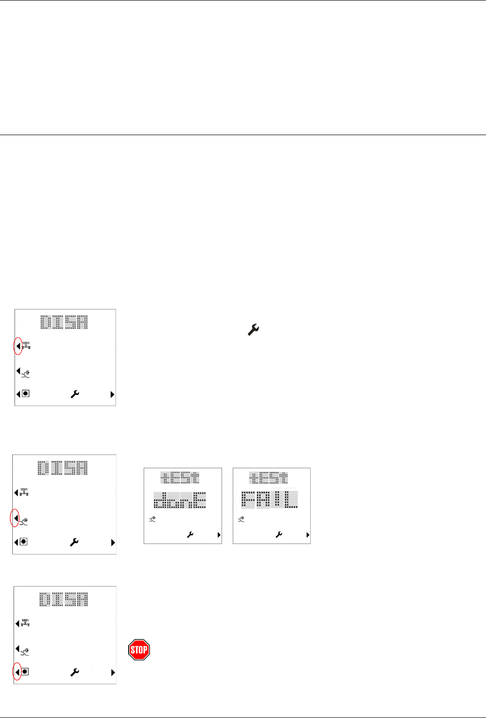
Addressing
When more than one QXM3.P... room operator unit is on the same trunk of the
KNX PL-Link bus, manual commissioning is done as follows:
1. Connect the SSA-DNT or the ABT to the room automation station and activate
the online commissioning function.
2. Load the web page "KNX PL-Link identification".
Activate the identification function.
The room automation station now waits for a signal from the room operator
unit.
3. On the room operator unit, simultaneously press the upper left and bottom
right button for at least 5 seconds (keys 1 and 8).
4. The "Engineering" page is displayed.
5. Press "Prog. Mode" (Key 2).
The display changes from "DISA" to "EnAB".
The tool identifies the current room operator unit that is operated and assigns
it.
6. After the device is commissioned, reset the device to programming mode to
“disabled” by pressing key 2.
Note: Programming mode resets to “disabled” each time the device restarts.
Connection test
1. Press "Conn. Test" (key 3) to test the KNX PL-Link connection.
The display shows the result of the connection test:
2. Press key 8 to return to the engineering page.
Reset to factory setting
Press "Fact. Reset" (Key 4). The device is locked and reboots within 10 seconds.
The room automation station deletes it from its device list. During this time, it is
safe to remove the device from the network.
If the bus plug remains connected, the device acts like a newly inserted device
requiring again automated or manual configuration.
Note! This operation resets all user preference data and
configuration settings to factory default.
This operation is irreversible.
Load application on the
room automation
station

9 / 16
QMX3... Wall-mounted sensors and room operator units for KNX PL-Link, KNX S-mode and KNX LTE-Mode CM2N1602en_07
Siemens Building Technologies 2017-05-22
Manual commissioning (KNX PL-Link, without display)
The devices are equipped with a programming pin and a red service LED on the
back side (see page 4)
1. Short press the programming pin (<0.5 s).
The device goes into programming mode; the service LED is continuously on.
The tool identifies the current room operator unit that is operated and assigns it.
2. After the device is commissioned, deactivate the programming mode by shortly
pressing the programming pin (<0.5 s). The service LED goes off.
Note: Programming mode resets to “disabled” each time the device restarts.
1. Medium press the programming pin (>2 s and <20 s) to test the KNX PL-Link
connection. After releasing the programming pin, the test of the KNX PL-Link
connection starts; the service LED flashes (1/4 s on, 7/4 s off).
After approx. 10 s, the test result is displayed:
– If the test is positive, the LED goes on continuously.
– If the test fails, it flashes (1 s on, 1 s off).
2. Short press the programming pin (<0.5 s) to stop displaying the result of the
connection test. The service LED goes off.
Long press the programming pin (>20 s). The device is locked and reboots within
10 seconds. The room automation station deletes it from its device list. During this
time, it is safe to remove the device from the network.
Note: there is no LED activity during this operation.
If the bus plug remains connected, the device acts like a newly inserted device
requiring again automated or manual configuration.
This operation resets all user preference data and configuration settings to
factory default.
This operation is irreversible.
Addressing
Connection test
Reset to factory setting
NOTICE

10 / 16
QMX3... Wall-mounted sensors and room operator units for KNX PL-Link, KNX S-mode and KNX LTE-Mode CM2N1602en_07
Siemens Building Technologies 2017-05-22
Commissioning (plug & play, KNX PL-Link)
When only one device is connected to the KNX PL-Link bus, the room operator
unit automatically establishes communications with the room automation station,
from where the functions are downloaded to the room operator unit (plug & play).
The following routine is executed:
Step With
display
Description
1
The Build number and the version number of the device are
displayed.
2
The Individual Address (IA) is downloaded to the device via
KNX PL-Link.
This step is skipped if the device is already configured.
Note: The configuration file can be downloaded any time; as a
result, these characters are displayed every time the room
automation station initializes download.
3a
After startup, the device goes to normal operation
(example view; picture depends on application in room
automation station).
3b
When configuration is faulty, "UCFG" is displayed, along with
the temperature that is measured by the local temperature
sensor.
In this case, manual commissioning must be performed (see
above).
11 / 16
QMX3... Wall-mounted sensors and room operator units for KNX PL-Link, KNX S-mode and KNX LTE-Mode CM2N1602en_07
Siemens Building Technologies 2017-05-22
Commissioning (KNX)
The devices are equipped with a programming pin and a red service LED for KNX
commissioning (see page 4).
1. Short press the programming pin (<0.5 s).
The device goes into programming mode; the service LED is continuously on.
The tool identifies the current room operator unit that is operated and assigns it.
2. After the device is commissioned, deactivate the programming mode by shortly
pressing the programming pin (<0.5 s). The service LED goes off.
Note: Programming mode resets to “disabled” each time the device restarts.
Long press the programming pin (>20 s). The device is locked and reboots within
10 seconds. The room automation station deletes it from its device list. During this
time, it is safe to remove the device from the network.
If the bus plug remains connected, the device acts like a newly inserted device
requiring again automated or manual configuration.
This operation resets all user preference data and configuration settings to
factory default.
This operation is irreversible.
Display and operation
Operation and display of the room operator unit depend on the control
program running on the room automation station.
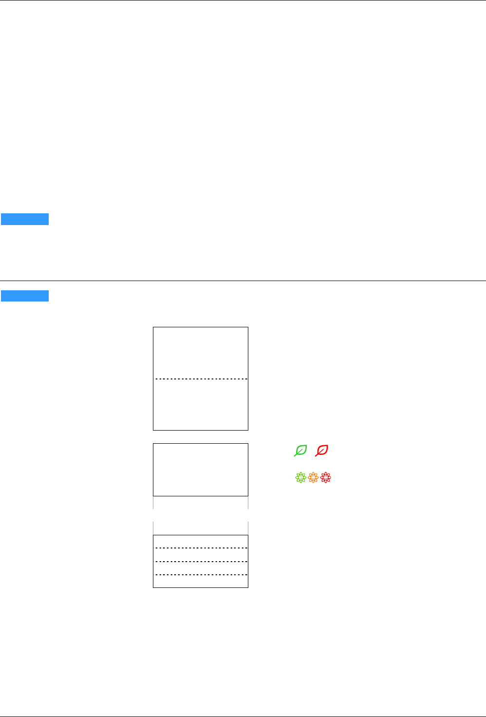
1
2
3
4
– –
– –
– –
– –
5
6
7
8
Keys 1...8 for room operator units
9
10
11
12
– –
– –
– –
– –
13
14
15
16
Keys 9...16 for switches
– –
– –
– –
– –
•
• / Green Leaf (green, red: Indicates
the Energy efficiency (room operator units)
• green, orange, red: Indicates the
air quality (multi sensor QMX3.P70)
– –
– –
9
–
–
13
• Each line can be a pair of keys or two
separate keys
(Light *), blinds **), scenes ***)
•
Each key is equipped with an LED (green)
10
–
–
14
11
–
–
15
12
–
–
16
*) Light ● The activity of the LEDs depends on the application running on the room automation
station
**) Blinds
● Always dual key operation (Up / Down)
● The activity of the LEDs depends on the application running on the room automation
station
***) Scenes
● Selecting a predefined scene (short press, <0.5.s). LED is on for 3 s.
● Saving a changed scene (long press > 5s).
LED flashes during 3 s. When it goes off, the user can release the key.
Addressing
Reset to factory setting
NOTICE
NOTICE
Numbering of the keys
LED display
(upper right corner)
Switches / keys
12 / 16
QMX3... Wall-mounted sensors and room operator units for KNX PL-Link, KNX S-mode and KNX LTE-Mode CM2N1602en_07
Siemens Building Technologies 2017-05-22
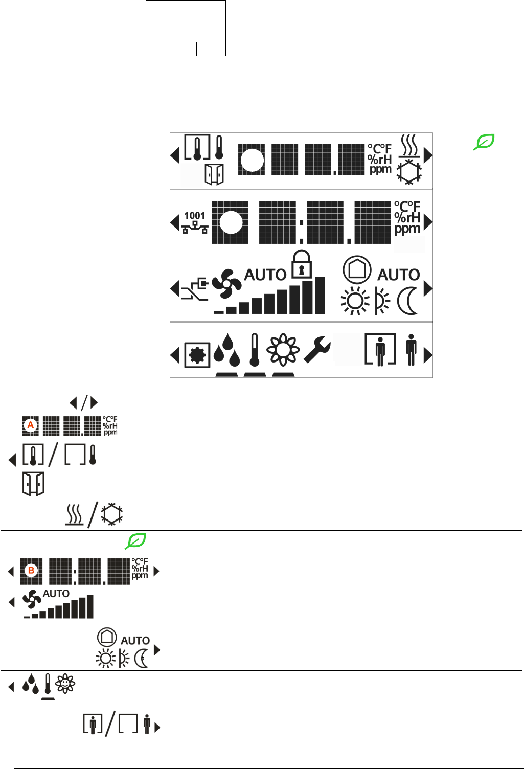
A
• A Display (temp., AQ, r.h.)
B
• B Setpoint adjustment (temperature) ****)
C
• C Operation (fan, operating mode)
D
E
• D Navigation
• E Presence / Comfort prolongation (display, operation)
****) Setpoint adjustment :
● Absolute value (23.5 °C) or relative value (+2 °C)
Key
Key
1
2
3
4
5
6
7
8
• An arrow indicates that an element can be operated
• Temperature display in °C or °F / humidity in % r.H. /
air quality in text, symbol, or ppm of CO
2
• Toggling (key 1) between indoor and outdoor measurement
(temperature, humidity, CO2)
• Indication that a window is open (connected window switch is active)
• Display of the plant state (Heating or Cooling / inactive)
Note: No manual switchover! Key 5 is used for Green Leaf
• Green Leaf function:
Pressing key 5 activates the RoomOptiControl function.
• Display of the relative or absolute setpoint for temperature
• Adjusting the setpoint using keys 2 and 6
• Display of the present fan speed (when automatic)
• Adjusting the fan speed using key 3 (or keys 3 and 7 if operation of room
operating mode is disabled)
• Display of the room operating mode (when automatic)
• Adjusting the room operating mode using key 7
• Navigation: toggle the display / setpoint setting between temperature /
humidity / CO
2
, using key 4. The black bar points to the displayed
information.
• Operation of the occupancy state (presence switch, Comfort prolongation)
• Activate the Comfort prolongation using key 8 (only available if enabled)
Display layout of
room operator units
Function of the
display elements
and keys
A
B

13 / 16
QMX3... Wall-mounted sensors and room operator units for KNX PL-Link, KNX S-mode and KNX LTE-Mode CM2N1602en_07
Siemens Building Technologies 2017-05-22
• Engineering functions (press keys 1 and 8 simultaneously during 5 s)
– Programming mode (key 2), same function as programming pin
– Connection test (Key 3)
– Reset device to factory settings (key 4)
Note: This operation is irreversible!
• Indicates that the room operator unit is locked by the system.
– Operation is disabled
– The display in line 1 shows the temperature from bus
Maintenance
The device can be cleaned with off-the shelf, solvent-free cleaning agents.
Do not use mechanical aids (rough sponge or similar materials) – only a soft, damp
cloth.
Technical data
Supply voltage
Operating voltage range
KNX / PL-Link DC 21...30 V
The device receives its power from the connected room automation station via the KNX / PL-Link interface
Power consumption
(from room automation station)
QMX3.P02
Max 7.5mA at DC 24 V
QMX3.P30
Max 7.5mA at DC 24 V
QMX3.P34
Max 7.5mA at DC 24 V
QMX3.P40
Max 7.5mA at DC 24 V
QMX3.P37
Max 10mA at DC 24 V
QMX3.P70
Max 15mA at DC 24 V
QMX3.P74
Max 15mA at DC 24 V
Operating data
Temperature sensor (all types)
Measuring element
NTC resistance sensor
Measuring range
0...
50 °C
Measuring accuracy (5…30 °C)
±0.8 K
Measuring accuracy (25 °C)
±
0.5 K
Relative Humidity Sensor (r.h.) (QMX3.P40; QMX3.P74; QMX3.P70)
Measuring range
10%...95% r.h.
Accuracy (20%...80%)
±4% at 25°C
Accuracy (0%...20%, 80%…95%)
±6% at 25°C
CO
2
Sensor (QMX3.P74; QMX3.P70) *)
Measuring range
400..10000 ppm
Measuring accuracy at 23 °C and 1013 hPa
for measured value 400...2000 ppm
for measured value >2000 ppm
±
(30 ppm +4% of measured value)
degraded accuracy.
Temperature dependency
±
2 ppm / °C typical
Pressure dependency
0.14% of measured value / hPa
Long-term drift
±
20 ppm per year
Service life
15 years
*) Notes on CO
2
sensor
• Function: The sensor determines the CO
2
concentration via infrared absorption measurement (NDIR). The sensor is maintenance
free in normal environments, thanks to the built-in self-correcting ABC (Automatic Baseline Correction) algorithm. This algorithm keeps
track of the sensor’s lowest reading within 8 days and corrects for any drift detected. The sensor also contains self-diagnostics to
assure proper operation during lifetime.
• Use: Normal environments, such as offices, class rooms, hotel rooms, or other non-permanently occupied areas, typically reach at
least once a week the CO
2
concentration of fresh air of 400 ppm. However, exposure to a lowest CO
2
concentration other than fresh
air, or incorrect altitude parameter setting, might result in reduced accuracy and incorrect operation.
• Rough handling during transport, storage or mounting might adversely affect accuracy during the first days of operation.
• The specified accuracy is reached after 25 days of continuous operation.
NOTICE
14 / 16
QMX3... Wall-mounted sensors and room operator units for KNX PL-Link, KNX S-mode and KNX LTE-Mode CM2N1602en_07
Siemens Building Technologies 2017-05-22
Display
Type
Segment LCD
Information displayed depends on the application in the
room automation station.
–
Room temperature, humidity, CO
2
–
Setpoint adjustment
–
Control mode
–
Manually selected fan speed
–
Control sequence
–
Scenes (LED next to the button)
–
etc.
Ports/interfaces
Type of port between room automation station and room
operator unit
KNX / PL
-Link
Baud rate
9.6 kbps
Standard KNX plug
Wire diameter0.8 mm, max. 1.0 mm
(solid conductors only)
Cable type
Solid conductors 2-core, twisted pair
Single cable length (from room automation station to room
operator unit)
<1000 m
Cables must comply with KNX specifications, see TRA Install. manual, CM111043
*)
Housing protection
Protection standard as per EN 60529
IP 30
Protection class
Insulation protection class
III
Ambient conditions
IEC 721
Normal operation
Transport
Environmental conditions
Class 3K5
Class 2K3
Temperature
0...50 °C
– 25...70 °C
Humidity
< 85 % rh
< 95 % rh
Mechanical conditions
Class 3M2
Class 2M2
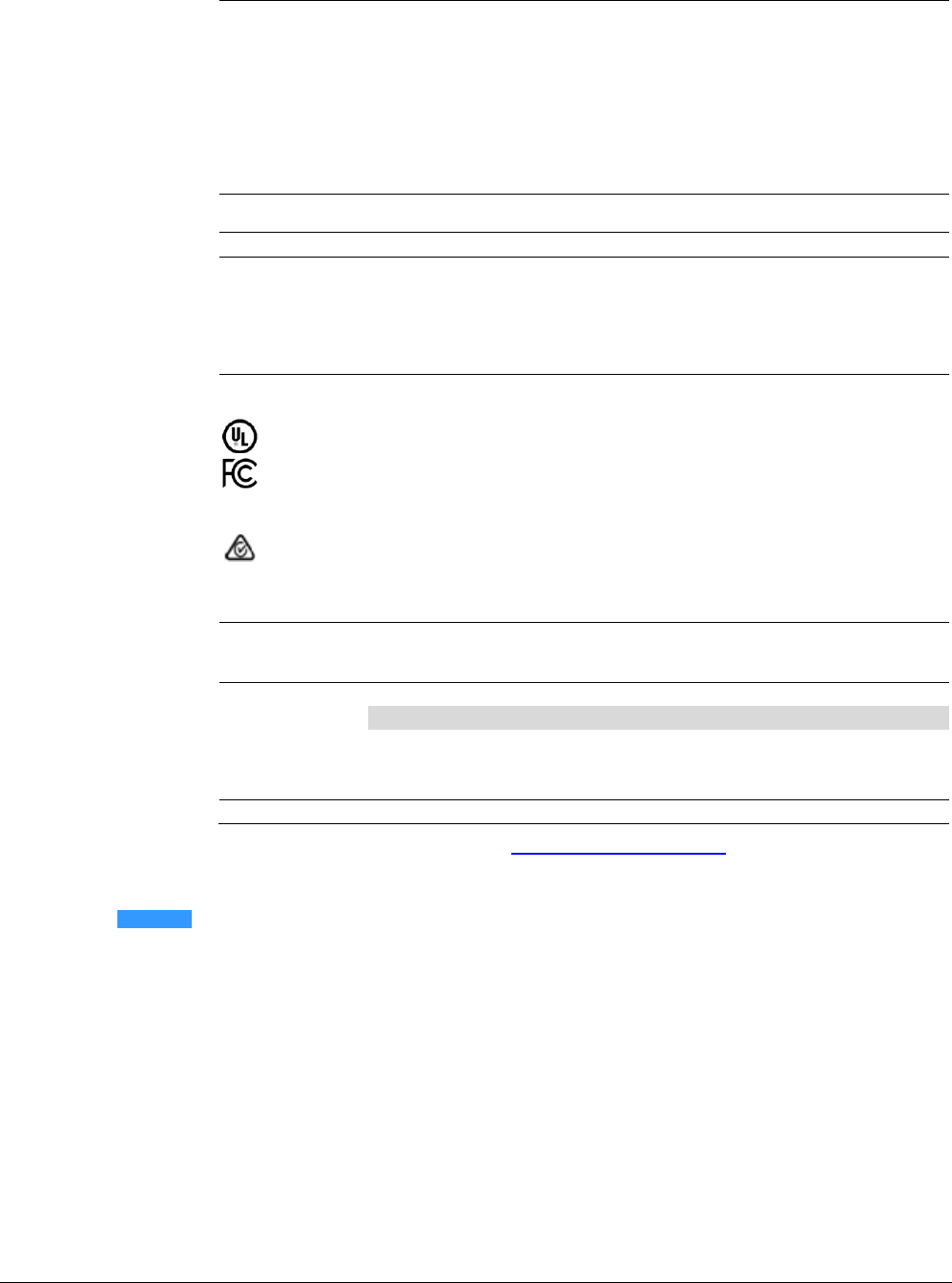
Standards and directives
EU conformity (CE)
CM2T1602xx
*)
compliance
UL916
compliance
Part 15 of the FCC rules
CSA compliance
C22.2 No 205
– Signal equipment
C22.2 No 0 – General Requirements
RCM Mark conformity (EMC)
AS/NZS 61000
-6-3
The product environmental declaration CM2E1602
*)
contains data on environmentally compatible product
design and assessments (RoHS compliance, materials composition, packaging, environmental benefit,
disposal)
Color
Front housing Models QMX3.Pxx
Models QMX3.Pxx-1BSC
Titanium white similar to RAL9010
Black similar to RAL9005
Weight [g]
QMX3.
P02
P30
P34
P37
P40
P70
P74
Operator unit
91
84
122
124
85
97
132
Base plate
20
20
20
20
20
20
20
Packaging
64
64
64
64
64
64
64
Total
175
168
206
208
169
181
216
*)
The documents can be downloaded from http://siemens.com/bt/download.
Notes on FCC rules
This device complies with Part 15 of the FCC Rules. Operation is subject to the following two conditions: (1)
this device may not cause harmful interference, and (2) this device must accept any interference received,
including interference that may cause undesired operation.
This equipment has been tested and found to comply with the limits for a Class B digital device, pursuant to
part 15 of the FCC Rules. These limits are designed to provide reasonable protection against harmful
interference in a residential installation. This equipment generates, uses and can radiate radio frequency
energy and, if not installed and used in accordance with the instructions, may cause harmful interference to
radio communications. However, there is no guarantee that interference will not occur in a particular
installation. If this equipment does cause harmful interference to radio or television reception, which can be
determined by turning the equipment off and on, the user is encouraged to try to correct the interference by
one or more of the following measures:
− Reorient or relocate the receiving antenna.
− Increase the separation between the equipment and receiver.
− Connect the equipment into an outlet on a circuit different from that to which the receiver is connected.
− Consult the dealer or an experienced radio/TV technician for help.
NOTICE
FCC warning
15 / 16
QMX3... Wall-mounted sensors and room operator units for KNX PL-Link, KNX S-mode and KNX LTE-Mode CM2N1602en_07
Siemens Building Technologies 2017-05-22
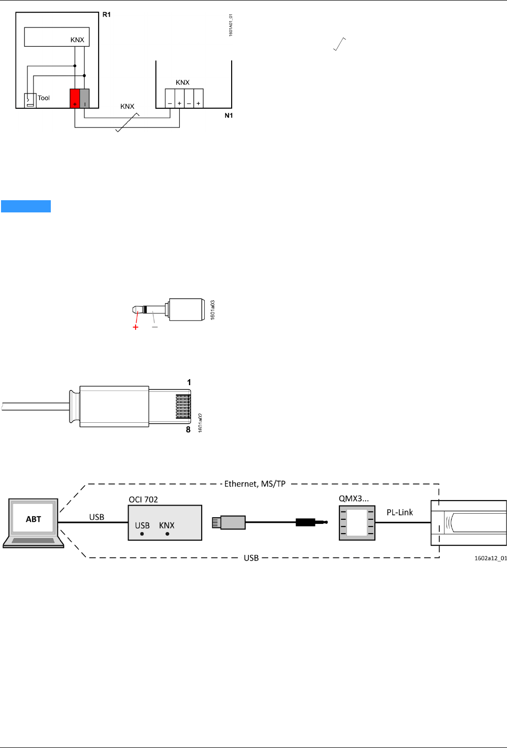
Connection
R1 QMX3... room operator unit
N1 Controller, actuator
= Twisted pair
+
Red
KNX PL-Link (positive)
–
Gray
KNX PL-Link (negative)
• Wires are NOT interchangeable.
The device is protected against faulty wiring, but communications does not work
on interchanged wires.
• The KNX / KNX PL-Link bus MUST NOT be connected to the tool plug,
only the tool.
RJ45 plug of the tool cable
1
CE+, KNX
2
CE−, KNX
3
N.C.
4
N.C.
5
Spannung 16 V
6
N.C.
7
Ident'pin
8
GND
Connect the ABT to load the application in the room automation station, or for
service purposes:
− Directly to the room automation station.
− To the room unit using the tool cable and the OCI702 service interface (see data
sheet A6V10438951).
KNX / PL-Link plug
NOTICE
Tool plug
(2.5 mm Jack)
Connect the tool
16 / 16
QMX3... Wall-mounted sensors and room operator units for KNX PL-Link, KNX S-mode and KNX LTE-Mode CM2N1602en_07
Siemens Building Technologies 2017-05-22
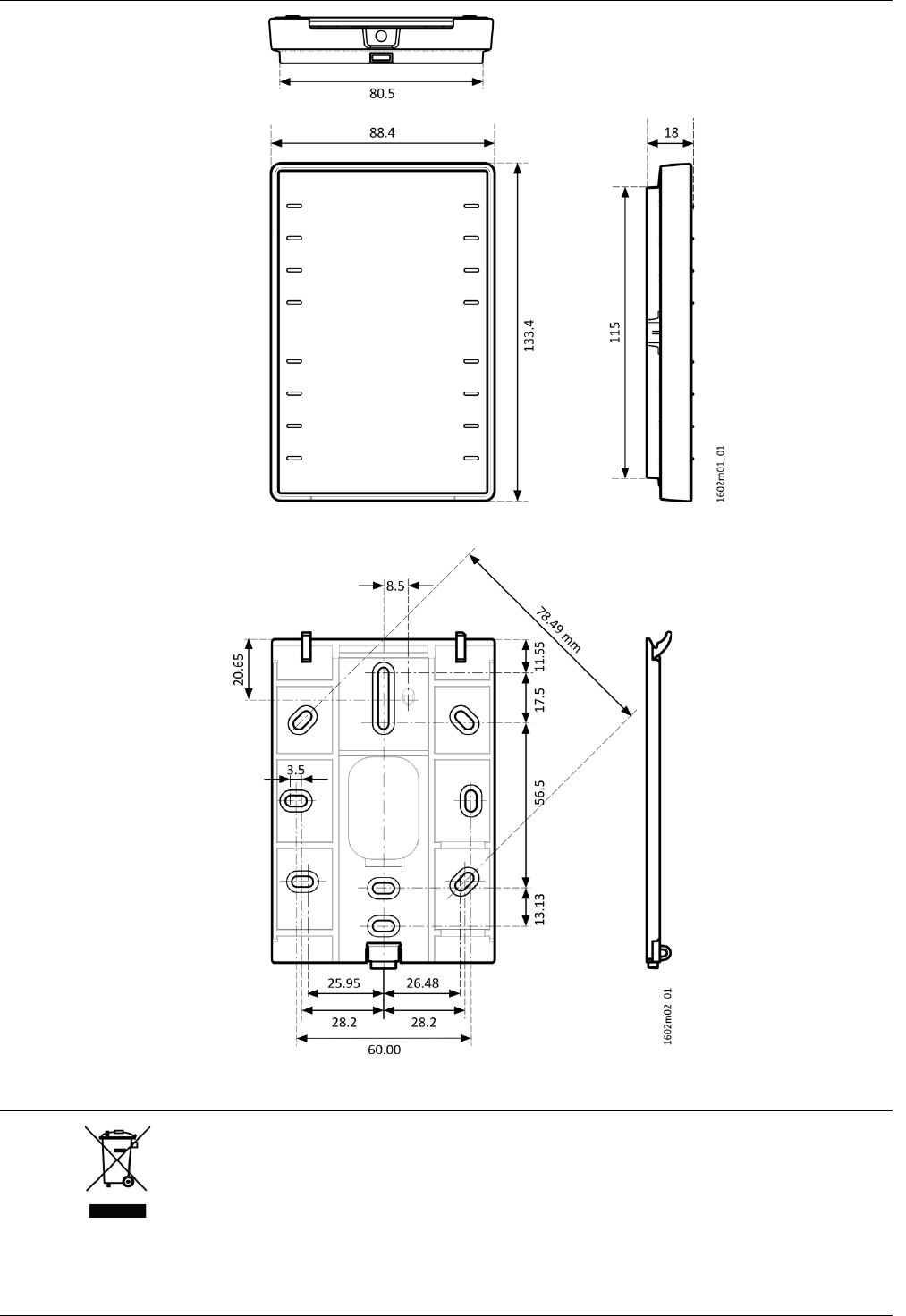
Dimensions
Disposal
The device is considered an electronics device for disposal in terms of European
Directive 2012/19/EU and may not be disposed of as domestic garbage.
• Dispose of the device through channels provided for this purpose.
• Comply with all local and currently applicable laws and regulations.
Siemens Switzerland Ltd, 2013 Subject to change
