Shaker Dining Table
Form meets function in this classic design
b y C h r i s t i a n b e C k s v o o r t
F I N E W O O D W O R K I N G
72
Photos, except where noted: Tom Begnal; this page: Michael Pekovich
COPYRIGHT 2007 by The Taunton Press, Inc. Copying and distribution of this article is not permitted.
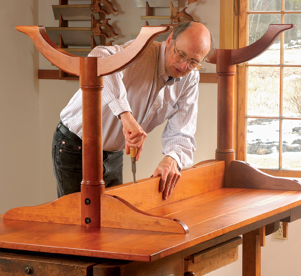
T
his table is based on a piece built at the Shaker commu-
nity in Hancock, Mass. (It’s now in the collection of the
Fruitlands Museum in Harvard, Mass.) The original, made
from cherry, is almost 11 ft. long, with a third trestle to support the
center. Such a length made good sense for communal dining, but
it’s not practical for most homes today. My version has only two
trestles, and I typically make the top either 8 ft. or 9 ft. long.
A trestle table has appeal for a few reasons. For one, it can be
“knocked down” without fuss. Remove the top from the base parts
and the stretcher from the trestles, and you can move the table
through doors and up or down stairs. Unlike most tables, which
have aprons around the perimeter to stiffen the structure, trestle
tables have a single center stretcher. This gives more vertical leg-
room. On the other hand, most trestle tables have flat feet, which
tend to get in the way of the feet of diners sitting at either end.
This Shaker design solves that inconvenience by replacing the flat
feet with arched feet. This simple change not only makes the piece
more ergonomic, but also gives it an especially graceful look.
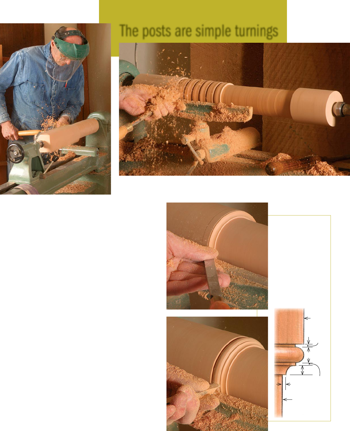
Most lathes will handle these posts
I make the posts first, using 16/4 stock. If this size isn’t readily
available, consider face-gluing two pieces of 8/4 stock from the
same board. Using the same board means the grain and color of
the pieces will be close and the glue joint less visible.
Mill the stock to about 3
5
⁄8 in. sq. and crosscut it to 24
1
⁄2 in. long.
Then mount it in a lathe and turn it to 3
1
⁄2 in. dia. At a point 6 in.
from the top and 4 in. from the bottom, use a parting tool and
calipers to establish the 2
3
⁄8-in. diameter of the center section.
Continue using the parting tool to make a series of 2
3
⁄8-in.-dia.
cuts between the end cuts. With these cuts serving as a depth
guide, use a gouge to reduce the entire center section to 2
3
⁄8 in.
Coves and beads.
Each end of the mid-
section terminates
in a cove and bead.
Mark the
7
⁄8-in. width
of the detail by lightly
touching a pencil point
against the spinning
post. Cut the cove with
a roundnose chisel or
small gouge, then the
bead with a diamond-
point or skew chisel.
The posts are simple turnings
Turn the blank. Becksvoort turns a 3
5
⁄8-in.-sq. blank to 3½ in. dia., then makes a series of
2
3
⁄8-in.-dia. parting cuts along the midsection, checking the diameter with calipers. After that,
with the parting cuts serving as guides, he reduces the entire midsection to 2
3
⁄8 in. dia.
2
3
⁄8 in.
dia.
3½ in.
dia.
1
⁄16 in.
1
⁄16 in.
¼ in.
½ in.
1
⁄16 in.
73
www.finewoodworking.com
S E P T E M B E R / O C T O B E R 2 0 0 7
COPYRIGHT 2007 by The Taunton Press, Inc. Copying and distribution of this article is not permitted.
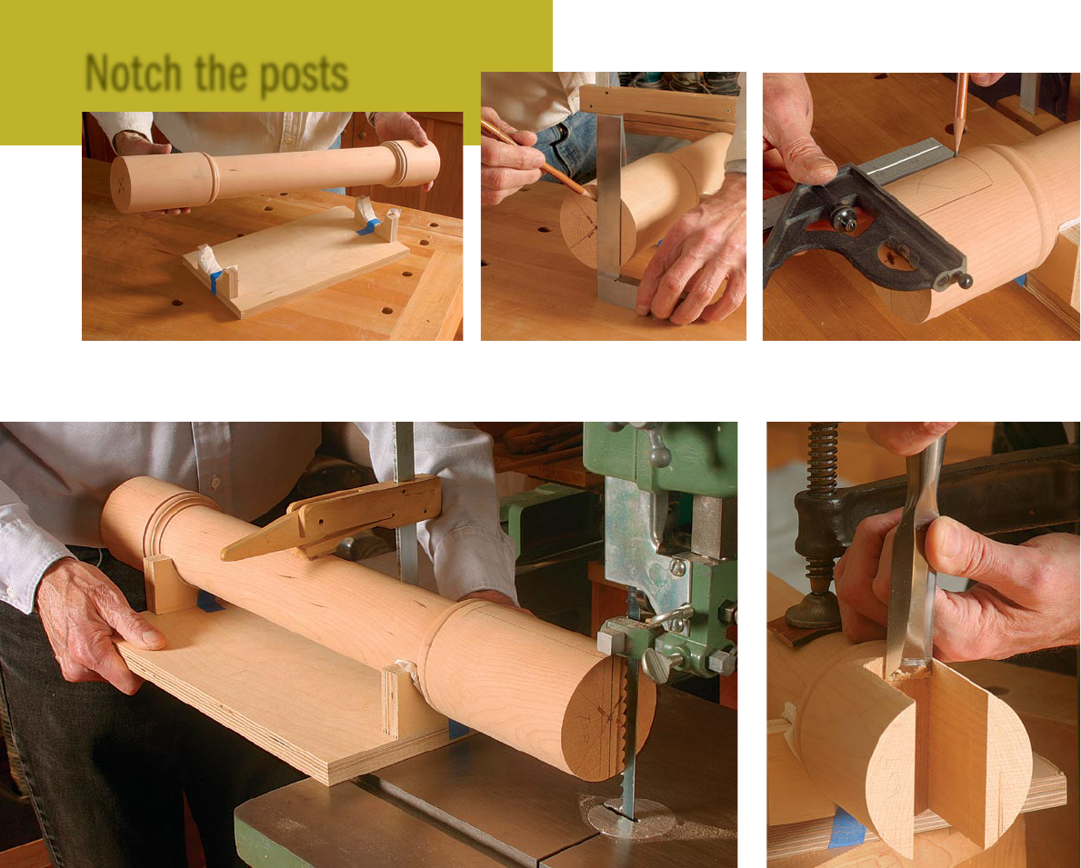
Notch the posts
dia. At each end of the center section, turn a small cove and a
bead with a small flat at each end of it (see drawing, p. 73). If your
turning skills are rusty, practice first on a shorter blank.
Jig simplifies post joinery
Once both posts are turned and sanded, they need to be notched
for the braces, feet, and stretchers. To hold them for layout and
machining, I clamp the posts to a shopmade cradle that consists
of a couple of U-shaped saddles screwed to a rectangular piece of
plywood. A narrow piece of paper towel in each saddle, held in
place with masking tape, helps prevent scratches on the posts.
Place the cradle on a bench (with the clamp between the opened
jaws of the vise so the cradle can rest flat). Use a square to lay out
the width and length of the notch on each end of the post. To lay
out a notch, first use a square to mark a vertical line through the
center of the turning. Using that centerline as a reference, mark
the width of the notch. Finally, mark the depth of the notch. The
notches can be cut by hand with a deep backsaw; but a bandsaw
does as good a job in less time. With the post clamped in the
cradle, carefully saw between the lines to the bottom of the notch.
Then, nibble out the bottom of the notch with the blade. As you
switch from one end to another, you’ll need to reposition the
clamp so that it doesn’t bump into the saw table as you cut.
Rout a shallow groove for the stretcher—There’s one more
machine cut to make on each post—a groove,
1
⁄4 in. deep by 1 in.
wide by 5 in. long, that will accept the end of the stretcher. You
can cut the groove with a chisel, but it’s easier on a router table.
Again, I use the cradle to support the post. A clamp gets in the
way on the router table, so I made a wooden yoke that serves as
a clamp. With the yoke screwed to the base of the cradle, the post
stays securely in place. Before tightening the yoke, make sure the
cheeks of the slot are parallel with the router-table surface.
Install a 1-in.-dia. straight bit in the router, and raise the bit to
make a
1
⁄4-in.-deep cut in the post. Adjust the router-table fence
so that when the cradle slides against it, the bit is centered on
the post. Also, clamp a stop block to the fence to stop the cradle
Build a cradle. Two saddles screwed to a base, ¾ in.
thick by 8 in. wide by 12½ in. long, create a cradle for the
post that simplifies a number of construction steps.
Lay out the location of the notches. With the cradle on a flat surface, use a square to
mark a vertical centerline on each end of the post (left). Measure and mark the width of
the notch, then use a square to scribe the notch depth (right).
Cut the two notches. With the post securely clamped in the cradle, use a bandsaw to
cut the notch on each end, following your layout lines by eye.
Hand work. Smooth the ends of the notches
and the cheeks with a sharp chisel.
F I N E W O O D W O R K I N G
74
Drawings: Bob La Pointe
COPYRIGHT 2007 by The Taunton Press, Inc. Copying and distribution of this article is not permitted.
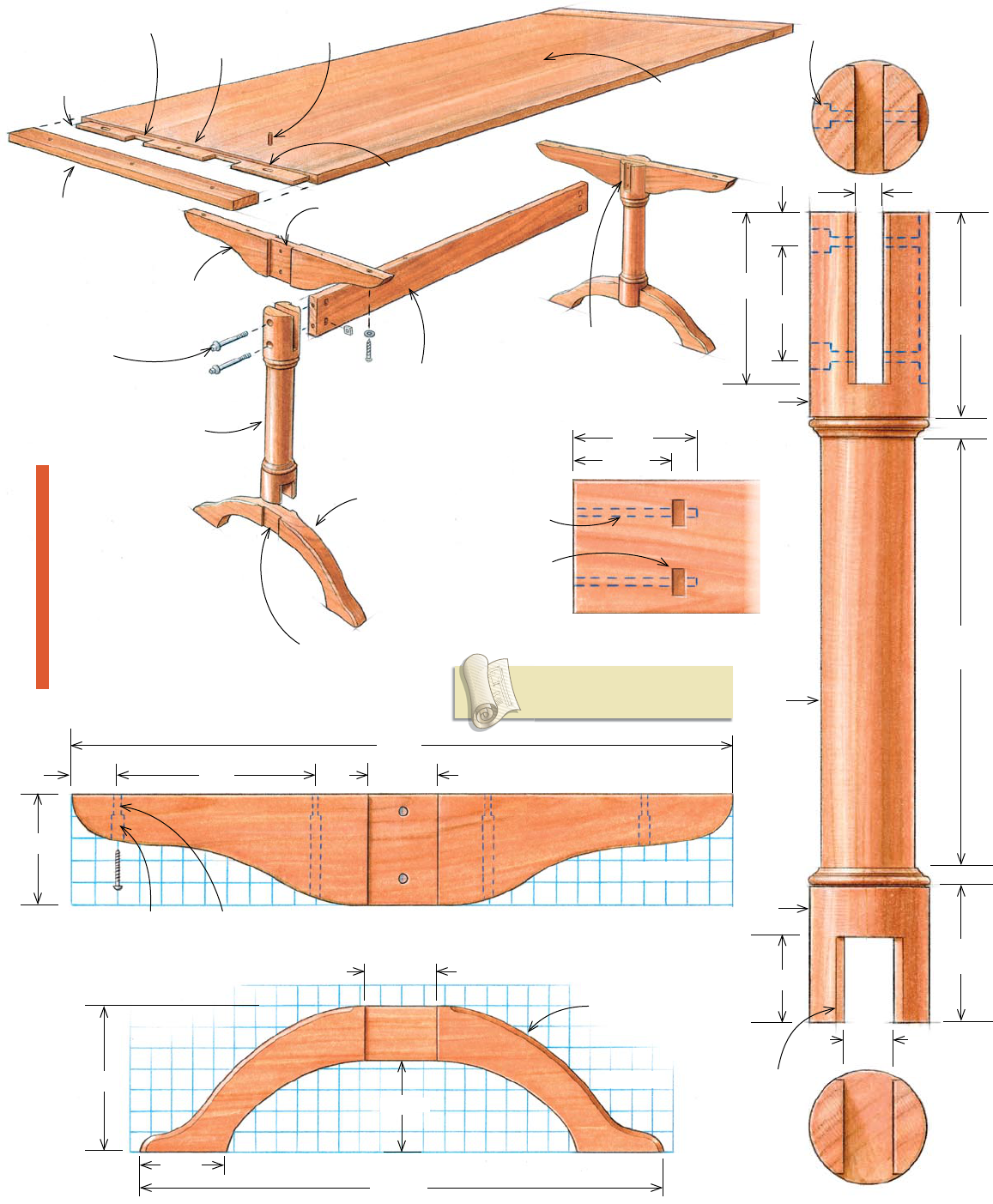
Post, 3½ in. dia.
by 24½ in. long
Brace, 1¼ in.
thick by 5 in. wide
by 30 in. long
Foot, 2 in. thick
by 7 in. wide by
25 in. long
Stretcher, 1 in.
thick by 5 in. wide
by 57½ in. long
Top, 1 in. thick by
36 in. wide by 94 in.
long (includes tenons
at each end)
Breadboard end,
1 in. thick by 3 in.
wide by 36 in. long
Bed bolt,
3
⁄8 in. dia.
by 6 in. long
End holes are
elongated.
Tenon,
3
⁄8 in.
thick by 2 in.
long
Stub tenon,
1
⁄4 in. long
Notch, ¼ in. deep
by 2
7
⁄8 in. wide
Notch, ¼ in. deep
by 3¼ in. wide
6 in.
7
⁄8 in.
12¾ in.
4 in.
5 in.
2½ in.
1 in.
3¼ in.
7
⁄8 in.
Flats,
1
⁄4 in. wide
¾ in.
1½ in.
25 in.
30 in.
5 in.
7 in.
4½ in.
45º chamfer
(top edge only)
7
⁄8-in.-dia.
counterbored
hole
Shank hole is
slotted to allow
wood movement.
2 in. 9 in. 3¼ in.
2
7
⁄8 in.
1-in.-dia. by
5
⁄8-in.-
deep counterbore
BRACE
POST
T R E S T L E
TA B L E
Lightly sand all
exposed corners
(except for the
foot chamfers) to
a
1
⁄8-in. radius. For
maximum strength,
use straight-grained,
defect-free wood for
the feet.
Peg,
3
⁄8 in. dia.
by 1 in. long
Add glue to
center tenon
only.
Stopped groove
for stretcher, ¼ in.
deep by 1 in. wide
by 5 in. long
STRETCHER END
Mortise for
square nut,
7
⁄8 in. deep
by
3
⁄8 in. wide
by 1 in. long
3½ in.
2½ in.
Bolt hole,
3
⁄8 in. dia.
Full-size plans for this table and
other projects are available at
FineWoodworking.com/PlanStore.
4 in.
FOOT
2
3
⁄8 in.
dia.
3½ in. dia.
3½ in.
dia.
S E P T E M B E R / O C T O B E R 2 0 0 7
75
www.finewoodworking.com
COPYRIGHT 2007 by The Taunton Press, Inc. Copying and distribution of this article is not permitted.
when the groove is 5 in. long. Hold the cradle firmly against the
fence as you slide it forward to feed the post in the bit.
The router bit leaves rounded corners at the end of each groove.
Use a chisel to cut them square.
Fit the other parts to the posts
Templates for the brace and feet can be found on p. 75, but you’ll
need to enlarge them to full size. I’m not fussy about pattern stock;
light cardboard or poster paper works just fine.
Use the patterns and a pencil to transfer the profiles to the
stock. Cut the parts on the bandsaw, staying just outside the lines.
Next, lay out and mark the location of the dadoes in the braces
and feet. These mate with the deep notches in the posts. They
can be cut by hand, with a router, or with a dado blade on the
tablesaw. To save time, I use the dado blade set for the widest
possible cut.
To support the braces and feet during the dado cuts, clamp a
long fence to the miter gauge. The fence should extend at least
15 in. on either side of the dado blade. Add a pair of stop blocks
to ensure that the shoulders of the dadoes align perfectly on both
sides of the joint. When setting the depth of cut, I leave the areas
between the dadoes a bit thick. That way, I can trim them with a
rabbet plane for a perfect final fit.
With the dadoes cut, I smooth concave edges of the braces and
feet using a spindle sander, and convex edges using a stationary
disk sander. Smooth the curved edges further by hand-sanding.
Now use the router table and a chamfer bit to rout a
1
⁄4-in.
chamfer along the top edges of the feet. Stop each chamfer at a
point
1
⁄2 in. from the dadoes.
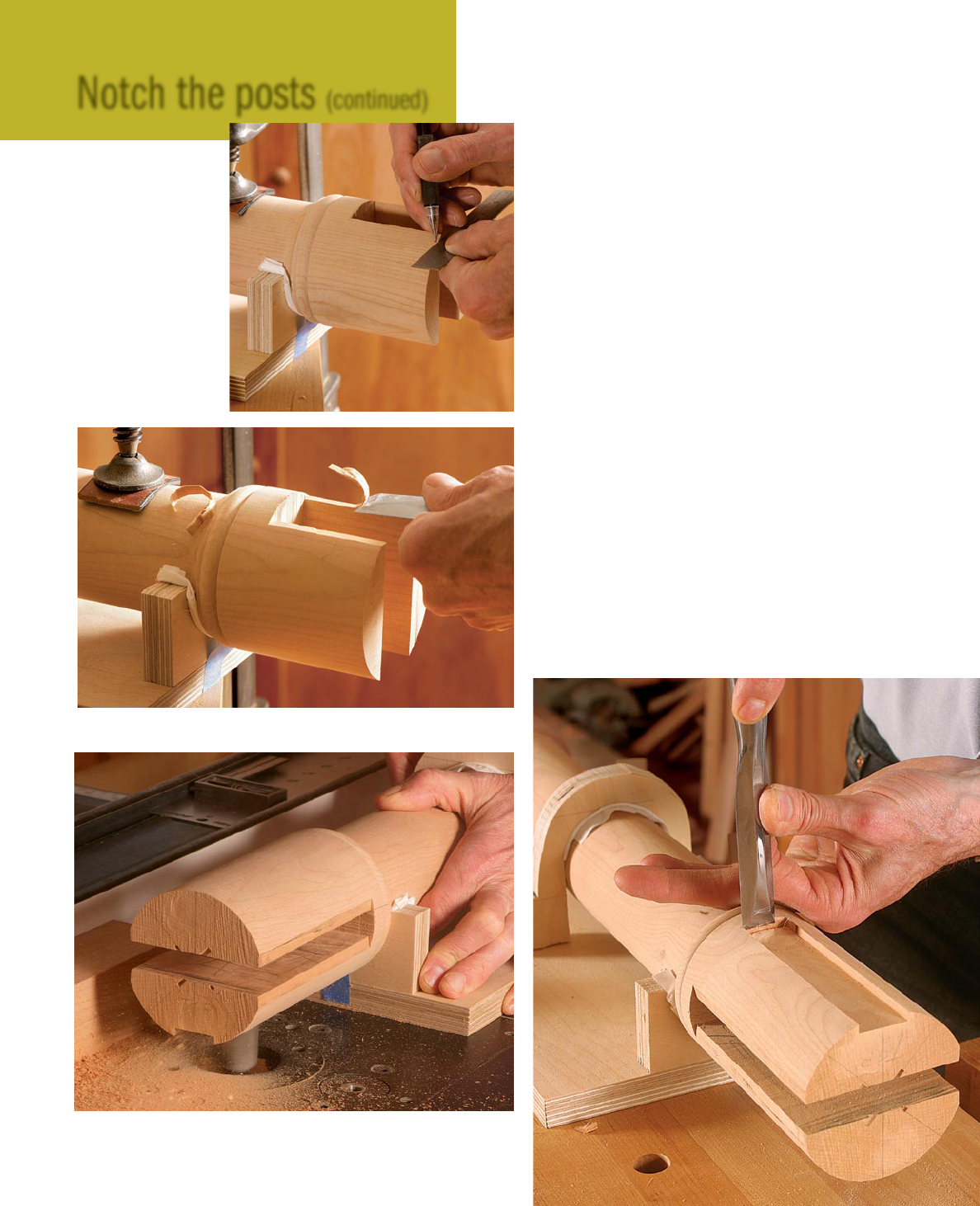
Notch the posts (continued)
Cut small shoulders.
Cut a flat on each side
of the notches to en-
sure gap-free contact
between the post and
the brace and foot.
First, lay out each flat
with a pencil and ruler
(right), then make a ver-
tical cut with a chisel to
establish the end point.
Finally, make horizontal
cuts with the chisel to
pare the stock to the
layout line (below).
Cut the groove for the stretcher. With a U-
shaped yoke screwed to the cradle serving as a
clamp, use a router table to cut a stopped groove
in the top end of the post (top). Square the round-
ed end left by the router bit with a chisel (right).
F I N E W O O D W O R K I N G
76
COPYRIGHT 2007 by The Taunton Press, Inc. Copying and distribution of this article is not permitted.
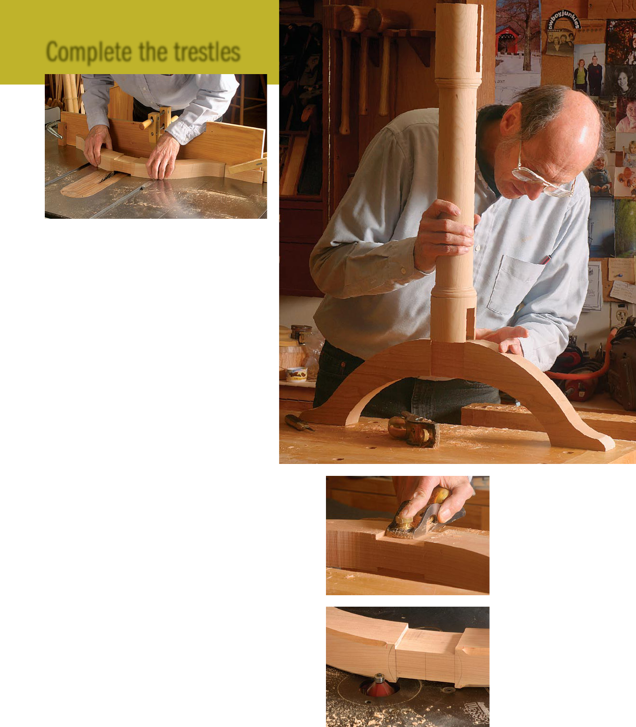
To fit a joint, first make a knife cut at the shoulders
of the dado to sever the wood fibers before trimming
the dadoes with a rabbet plane. When the joint begins
to engage, I mark the leading edges of the slots with a
pencil, which shows me exactly where the joint is still
tight. A few more strokes with the rabbet plane and the
joint should fit snugly.
Once all braces and feet are fitted to their respective
posts, the parts can be glued and clamped to create a
trestle. A pair of clamps, each spanning from brace to
foot, is all that’s needed. After that, at one end of the
trestle, measure the distance from the top edge of the
brace to the bottom edge of the foot. Do the same at
the other end. The measurement should be the same. If
they differ, adjust the pressure on the two clamps until
the measurements agree. Once dry, sand the bottom of
the post and the underside of the arched foot until flush.
When making the stretcher, I start with slightly thicker stock.
Then I make light passes with a thickness planer until the stretcher
fits snugly in the groove routed in the top of the post.
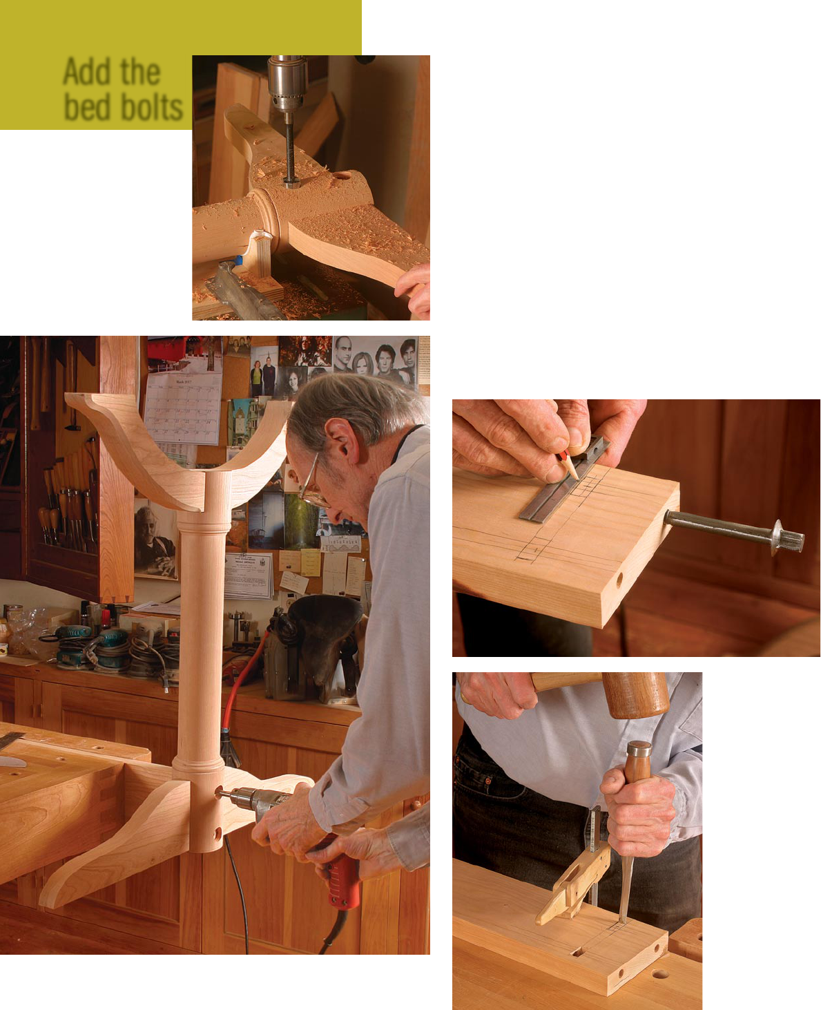
How to install bed bolts
Each trestle attaches to an end of the stretcher with a pair of
3
⁄
8
-in.
by 6-in. bed bolts and nuts (available from Horton Brasses; www.
horton-brasses.com). Each bolt extends through a post and brace
and into the end of the stretcher. The end of the bolt threads
through a nut mortised into the stretcher. When the bolt and
nut are tightened, the stretcher and trestle are pulled together to
produce a rock-solid joint.
The bed-bolt work starts at the drill press. Once again, the cradle
comes in handy. Use the yoke to secure the trestle to the cradle,
with the stretcher groove facing down. Make sure the sides of the
brace and trestle are parallel to the worksurface. If the parts tilt,
the holes won’t be square.
Measuring from the top end of the post, mark the hole centers
at 1 in. and 4
1
⁄4 in. Position the cradle so that a 1-in. Forstner bit
is centered on the upper hole. Clamp the cradle to the drill press,
Complete the trestles
Dado the legs and braces. Cut a wide dado on each side of
the brace and foot (above). Use the tablesaw miter gauge with
a long auxiliary fence to support the parts during the cuts. A
pair of stop blocks helps ensure that the ends of the dadoes
end up perfectly aligned on both sides of the parts.
Dry-fit the parts. Check
the fit of the posts to
each dado (above). If too
tight, use a rabbet plane
(left) to trim the sides or
bottom of the dado.
Rout chamfers. A cham-
fer bit in a router table is
used to chamfer the top
edges of the feet. Stop
the cut ½ in. short of the
dado.
S E P T E M B E R / O C T O B E R 2 0 0 7
77
www.finewoodworking.com
COPYRIGHT 2007 by The Taunton Press, Inc. Copying and distribution of this article is not permitted.
and then bore a
5
⁄8-in.-deep hole to accept the head of the bed
bolt. Replace the Forstner bit with a
3
⁄8-in.-dia. brad-point bit and
bore a hole completely through the post and brace. Repeat the
process for the remaining holes.
Next, clamp the stretcher in a vise and temporarily mount one
of the trestles. Transfer the
3
⁄8-in.-dia. bit from the drill press
to a portable drill. Using the holes in the trestle as guides, drill
matching holes in the end of the stretcher. Remove the trestle and
continue drilling until the hole is at least 3
1
⁄2 in. deep, measured
from the end of the stretcher.
Portable drills rarely produce a hole perfectly square to the
stretcher ends. So, to make sure the mortise for the nut is properly
located, I use a bed bolt as a guide. Allow a good portion of the
bolt to extend from the hole. Then place a long ruler so it’s cen-
tered along the length of the exposed bolt. Use a pencil to extend
the centerline along the face of the stretcher. With the centerline
showing the location of the bolt hole, measure 2
1
⁄2 in. from the
end of the stretcher, and lay out the location of the mortise for
the nut. A few minutes’ work with a chisel yields a mortise just
Add the
bed bolts
Start by drilling. With
a trestle clamped in
the cradle, and the
cradle clamped to the
drill-press table, use a
1-in.-dia. Forstner bit to
drill a
5
⁄8-in.-deep hole
(right). Then, remove the
Forstner bit and use a
3
⁄8-in.-dia. brad-point bit
to drill a hole complete-
ly through the post.
Drill holes in the ends of the stretcher. Add a trestle to the stretcher
temporarily, then use a
3
⁄8-in.-dia. brad-point bit to extend the bed-bolt
hole slightly into the end of the stretcher. After that, remove the trestle
and drill deeper to complete the hole.
Lay out the
location of the
bed-bolt nuts.
With a bed bolt in a
stretcher hole serv-
ing as a guide (in
case the hole isn’t
drilled perfectly
square), mark the
location of the bed-
bolt nut (above). Cut
the mortises for the
nuts (left) just deep
enough to allow the
bolt to thread into
the nut.
F I N E W O O D W O R K I N G
78
Photos, facing page: Michael Pekovich
COPYRIGHT 2007 by The Taunton Press, Inc. Copying and distribution of this article is not permitted.
big enough to accept the nut. You’ll know the alignment is OK
if you can slip the bolt into the hole and thread it into the nut. I
use a special bed-bolt wrench (available from Horton Brasses; a
12-point socket also works) to turn and tighten the bolts.
With the holes drilled and all the mortises cut, you can mount
the trestles to the stretcher.
Build the top and breadboard ends
I make the tabletop by edge-gluing 1-in.-thick stock, using three
or four well-matched boards across the 36-in. width.
Breadboards are applied to either end. The original table, made
from
7
⁄8-in.-thick stock, had a
1
⁄4-in.-thick by
1
⁄2-in.-long tongue
cut fully across each end of the top and pinned to allow for wood
movement. The tongue fit into a corresponding groove cut across
the entire length of the breadboard end. I make my tenons lon-
ger for added strength (see “Keeping Tabletops Flat,” FWW #183,
pp. 32-37, for more detailed instructions).
The top is attached with screws driven through counterbored
holes in the braces and stretcher. To allow the top to expand and
contract in width due to seasonal changes in humidity, be sure
to elongate the shank holes in the braces.
For a finish, I use an oil-and-varnish mix (equal parts of each),
applying three coats to all the table surfaces, including the top
and bottom of the top and breadboard ends. For added durability,
the top then gets two more coats. •
Contributing editor Christian Becksvoort builds furniture in New Gloucester,
Maine.
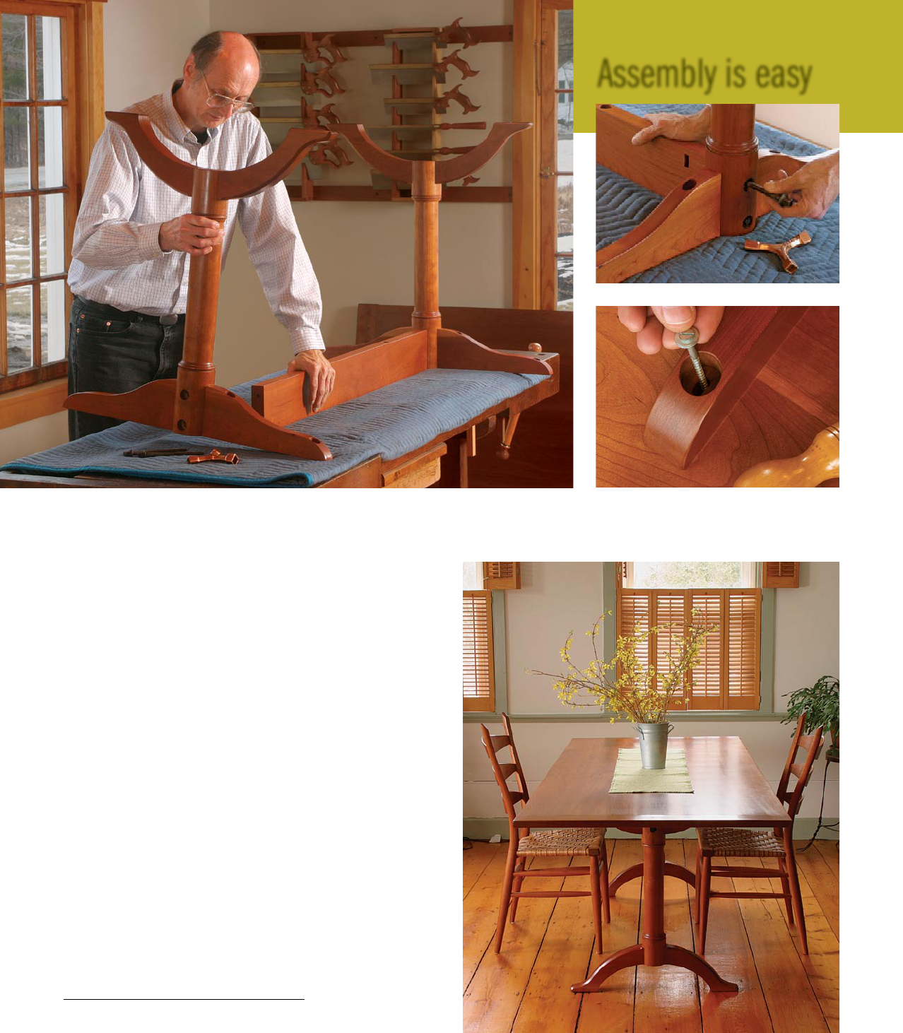
Assembly is easy
Put it together. After all the parts have been sanded and finished, it’s finally time to put the table
together. With the table parts upside down, slide the ends of the stretcher into the post grooves and
slip the bed-bolt nuts into the mortises in the stretcher. Then, insert the bolts (top right).
Attach the top. A screw and washer go into
each counterbored hole in the braces. The slot-
ted shank hole allows wood movement.
S E P T E M B E R / O C T O B E R 2 0 0 7
79
www.finewoodworking.com
COPYRIGHT 2007 by The Taunton Press, Inc. Copying and distribution of this article is not permitted.
