Installation, Operation and
Maintenance Manual

Table of Contents
I. Introduction ............................................................................. 3
II. Why use AGM
2
batteries? ....................................................... 3
III. Safety....................................................................................... 4
I V. Getting started ........................................................................ 4
A. Installation ..................................................................... 4
B. Battery connections ...................................................... 5
C. Battery cabling .............................................................. 6
D. Torquespecications .................................................... 6
V. Technical details ..................................................................... 8
A. Operating temperature range ....................................... 8
B. Understanding state of charge ..................................... 8
C. Storage and self-discharge ........................................... 8
D. Battery life expectations ............................................... 9
E. Float applications .......................................................... 9
F. Charging ...................................................................... 10
G. Parasitic loads ............................................................. 13
H. Testing .......................................................................... 13
I. Maintenance ................................................................ 14
J. Ventilation .................................................................... 15
K. Winter storage ............................................................. 15
L. Warranty considerations ............................................. 15
VI. Additional information .......................................................... 16
VII. FAQs ...................................................................................... 16
VIII.Denitionsofacronyms ........................................................ 17
View ODYSSEY battery
technical specications
3
AMER-EN-IOM-ODY-0523
www.odysseybattery.com
I. INTRODUCTION
ODYSSEY
®
batteries are manufactured by EnerSys
®
using its unique Absorbed Glass Mat (AGM) Thin
Plate Pure Lead (TPPL) technology to deliver twice the power and three times the life of conventional
AGM batteries.
Bringing together the technologies incorporated into ODYSSEY batteries and NorthStar batteries has
integrated years of intelligence, research and development, resulting in the creation of the next
generation of AGM - TPPL batteries. AGM
2
is a unique design of Valve Regulated Lead Acid (VRLA)
batteries that combines three major technical advancements in one battery: super high-grade
materials + refined chemical formula + TPPL technology. This sets AGM
2
batteries apart in terms of
power, fast-charge acceptance, shelf life, durability and most of all exceptional value for your
investment.
Throughout their design cycle life, AGM
2
batteries can provide engine cranking pulses of up to 2700
amps for five seconds at 77°F (25°C), while delivering over 400 charge/discharge cycles to 80% Depth
of Discharge (DOD). This challenges all typical starting batteries, which are only designed for high cur-
rent for short durations, to perform poorly when deeply discharged repeatedly.
Likewise, a typical deep cycle battery, which is designed to provide relatively low current for a long
duration of time, cannot provide the high current bursts that are needed for starting applications.
AGM
2
technology allows one battery to provide both excellent cycling life and high-power capability
for many applications. AGM
2
batteries excel in both starting and deep cycling without compromising
lifespan or performance, making them an excellent choice for a wide range of applications such as
heavy-duty trucks, recreational vehicles, marine, emergency power and much more.
II. WHY USE ODYSSEY
®
AGM
2
BATTERIES?
• Longservicelife–designlifeof8-12yearsinfloatapplicationsand3-10yearsinnon-float
applications at 77°F (25°C).
• Fastcharging–extremelylowinternalresistanceallowshigh-currentcharging,whichreduces
charge time.
• Excellentcyclelife–provideupto900cycleswhendischarged50%.
• Lowtemperatureperformance–evenatsub-zerotemperaturesdownto-40°F(-40°C),battery
performance allows for quick engine starts or deep discharges.
• Longshelflife–canbestoredforuptotwoyearsat77°F(25°C)andlongeratlowertemperatures.
• Deepdischargerecovery–itispossibletorecoveradeeplydischargedAGM
2
battery. There is
more information on that process later in this manual. However, overall battery life will be affected.
• Virtuallymaintenance-free–noneedtoaddwatertobatteries.
• Superiorvibrationresistance–highcompressiondesignandhigh-strengthplasticconstruction
give these batteries extreme shock and vibration resistance.
• Mountingflexibility–canbemountedinanypositionexceptinverted/upsidedownintypical
starting applications.
• Easyshipping–approvedforshipmentasnon-hazardouscargobytheU.S.Departmentof
Transportation.
• ThemanagementsystemsgoverningthemanufactureofthisproductareIATF16949,ISO9001
andISO14001certified.
AMER-EN-IOM-ODY-0523
www.odysseybattery.com
4
III. SAFETY
Batteries can deliver a large amount of power, which can cause injury or death if not handled safely.
Please follow these guidelines any time you are working around batteries.
• Personalprotectiveequipmentincludingglovesandsafetyglassesshouldbeworn.
• Insulatedtoolsshouldbeused.
• Watches,braceletsorothermetalobjectsshouldberemoved.
• Donotplaceanyobjectsontopofthebattery.
• MakesurethechargingsystemissetforAGMbatteriesandinlinewithadvisedcharging
specifications.
• Donotchargebatteriesifthetemperatureisabove104°F(40°C).
IV. GETTING STARTED
A. INSTALLATION
ODYSSEY
®
AGM
2
batteries are shipped from the factory at a full State of Charge (SOC) and should be
readyforinstallationoutofthebox.Intypicalstartingapplications,measurethebattery’svoltage;ifit
is12.65voltsorhigher,thebatterycanbeinstalled.Ifthevoltageislowerthan12.65volts,thebattery
should be charged. Multiple battery configurations should be matched voltage. Refer to the Charging
section in this manual if needed.
To replace an existing battery, follow the steps below:
1. Besuretoweartheappropriatepersonalprotectiveequipment.
2.Notetheorientationoftheexistingbattery’spositiveandnegativeterminals.
3. Disconnectthecables,negativefirst,fromtheoldbatteryfollowingvehiclemanufacturer
guidelines if applicable. The old battery should be returned to a battery dealer for proper
recycling.
4. Inspectthebatterycablesforcorrosion,aciddamageorinsulationdeteriorationandreplaceif
needed.
5. Position the new ODYSSEY AGM
2
battery in the battery tray and secure it
properlytothevehicle–heightadaptersmaybeneededandareavailableforsomesizes.
6. ConnectthepositivecablefromtheignitiontothePositive(+)terminalofthebattery.
7. Connect the negative cable from the ignition or chassis to the Negative (-) terminal of the battery.
8. ProperlytorquetheconnectionperthespecificationinTable2onpage6.
Thestepsaboveapplytoasingle,12-voltbattery.Thereareotherapplicationsthatmayrequire
batteriestobeconnectedinparallelorseries.Itisimportanttotakenoteofthebattery’srequired
configurationbeforetheexistingbatteriesareremoved.Ifthereisanyquestionaboutthebattery
configuration, refer to the documentation that was supplied with the device being powered. ODYSSEY
AGM
2
batteries can be installed on their side or end if needed due to space constraints.
NOTE: This is a valve regulated sealed battery and never needs to have water or electrolyte (acid)
added. Warranty will be void if opened!
5
AMER-EN-IOM-ODY-0523
www.odysseybattery.com
ANY OF THE FOLLOWING WILL VOID THE WARRANTY ON YOUR ODYSSEY
®
BATTERY:
•REMOVINGTHELABELEDCOVER
•REMOVINGORDESTROYINGTHEBATTERY’SDATECODE
ODYSSEY
®
EXTREME BATTERY WARNING –DONOTUSEANYTYPEOFOIL,ORGANICSOLVENT,
ALCOHOL,DETERGENT,STRONGACIDS,STRONGALKALIS,PETROLEUM-BASEDSOLVENTOR
AMMONIASOLUTIONTOCLEANTHEBATTERYCOVERSANDBATTERYTOPS.THESEMATERIALS
MAYCAUSEPERMANENTDAMAGETOTHEBATTERYCOVERSANDBATTERYTOPSANDWILL
VOIDTHEWARRANTY.
ODYSSEY
®
PERFORMANCE BATTERY WARNING–PROLONGEDEXPOSUREANDORIMMERSION
INTOANYTYPEOFOIL,ORGANICSOLVENT,ALCOHOL,DETERGENT,STRONGACIDS,STRONG
ALKALIS,PETROLEUM-BASEDSOLVENTORAMMONIASOLUTIONTOCLEANTHEBATTERY
COVERSANDBATTERYTOPSMAYCAUSEPERMANENTDAMAGETOTHEBATTERYCOVERSAND
BATTERYTOPSANDWILLVOIDTHEWARRANTY.
DONOTSHORTCIRCUITYOURODYSSEY
®
BATTERY’STERMINALS!
Remove any metallic items such as watches, bracelets and other personal jewelry.
B. BATTERY CONNECTIONS
Here are some general guidelines regarding different types of battery connections:
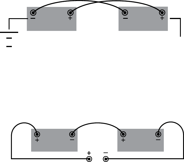
• Seriesconnectionsareusedtoincreasebatteryvoltagebyconnectingthepositiveterminalof
onebatterytothenegativebatteryofanotherbattery.Inthisconfiguration,theoverallcapacityof
the battery is equal to the capacity of one battery. Series systems are wired as shown in Battery
Sketch1.
PLEASE NOTE:Whenreplacingmultiplebatteries,eachbatteryshouldbeofasimilar
SOC.
Battery Sketch 1
• Parallelconnectionsareusedtoincreasethebatterycapacitybyconnectingthepositiveterminal
of one battery to the positive terminal of a second battery. Likewise, the negative terminals are
connected.Inthisconfiguration,thesystemvoltageisthevoltageofonebattery.Parallelsystems
are wired as shown Battery Sketch 2:
Battery Sketch 2

AMER-EN-IOM-ODY-0523
www.odysseybattery.com
6
C. BATTERY CABLING
Since battery cables are the connection between the battery, the charging system and the device
beingpowered,itisimportantthattheyareproperlyinstalled.Improperlyinstalledcablescanresult
inpoorbatteryperformance,terminaldamageorevenfire.Cablesshouldbesizedbasedonthe
amountofcurrenttheyareexpectedtocarryintheapplication.RefertoTable1forcablecurrent
ratingsaccordingtoNECTable310.15(B)16forcoppercablesratedat167°F(75°C).Ifitisnecessary
for a cable to be longer than six feet, a heavier gauge wire should be considered to avoid excessive
voltage drop.
AWG mm2 Amps
14 2.5 20
12 4 25
10 6 35
8 10 50
6 16 65
4 25 85
2 35 115
1 50 130
1/0 55 150
2/0 70 175
4/0 120 230
Table 1
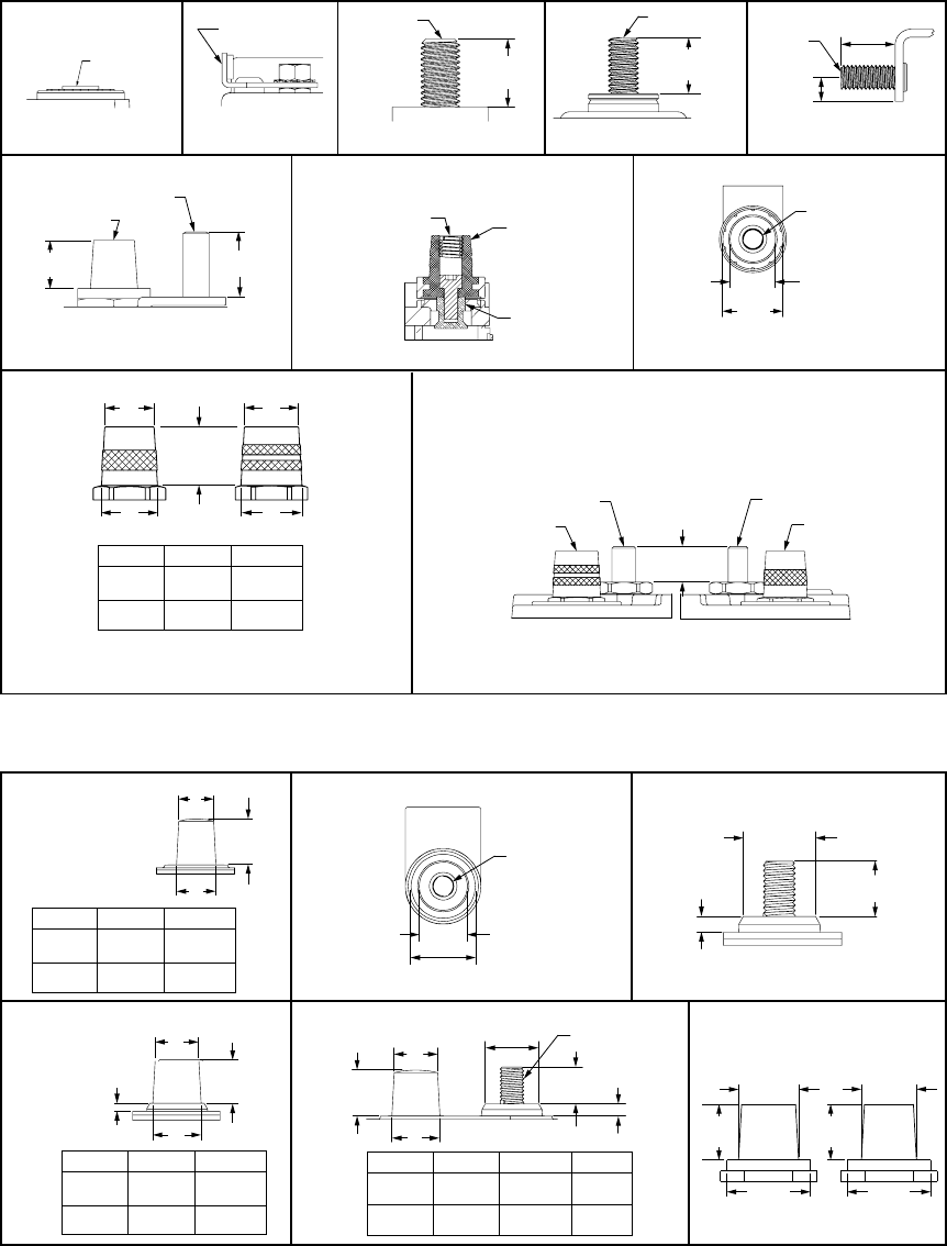
D. TORQUE SPECIFICATIONS
Eachterminaltypehasadifferenttorquespecification.Under-tighteningofconnectionscanleadto
short circuit and electrical damage. Over-tightening can cause physical damage to the battery
terminal. Refer to Table 2 below for the recommended torque specification based on the terminal type.
Terminal Type Details
Maximum Torque
[in-pounds]
Maximum Torque
[Nm]
Stud3/8-16”HD AllG31,Marineand8D 200 22.6
Stud3/8-16” ODS-AGM6M 100 11.3
Stud5/16-18” All Marine 100 11.3
SideTerminal3/8-16”Receptacle G75 G78 60 6.8
M4 Receptacle ODS-AGM8E(PC310) 8.9 1
M6Receptacle ODS-AGM16B,16CL 40 4.5
M6Receptacle ODS-AGM15L,16L 50 5.6
M6Receptacle ODS-AGM28*, 42*, 70* 60 6.8
M6Receptacle ODS-AGM***FT 35 3.9
*ForSAEtorquespecicationrefertovehiclemanufacturer’sspecication.
Table 2
7
AMER-EN-IOM-ODY-0523
www.odysseybattery.com
0.73”
(18.5 mm)
A
B
ODP-AGM34
ODP-AGM34R
ODP-AGM48 H6 L3
ODP-AGM65
ODP-AGM75 86
ODP-AGM94R H7 L4
ODP-AGM49 H8 L5
TERMINAL
0.682” 0.759“
(17.3 mm) (19.3 mm)
0.619” 0.696”
(15.7 mm) (17.7 mm)
POSITIVE
NEGATIVE
DIM A DIM B
SAE TERMINALS
TERMINAL
0.682” 0.759”
(17.3 mm) (19.3 mm)
0.619” 0.696”
(15.7 mm) (17.7 mm)
POSITIVE
NEGATIVE
DIM A DIM B
B
A
0.68”
(17.3 mm)
0.13”
(3.2 mm)
SAE TERMINAL
ODP-AGM31A
A
B
0.20”
(5.1 mm)
0.59”
(15.0 mm)
0.85”
(21.6 mm)
0.73”
(18.6 mm)
TERMINAL
0.682” 0.759”
(17.3 mm) (19.3 mm)
0.619” 0.696”
(15.7 mm) (17.7 mm)
POSITIVE
NEGATIVE
DIM A DIM B
THREAD
3/8-16
5/16-18
THREAD
MARINE (DUAL TERMINAL)
ODP-AGM31M
ODP-AGM34M
ODP-AGM4D
ODP-AGM8D
3/8-16” THREAD
0.34” DEEP
0.85”
(21.6 mm)
1.12”
(28.5 mm)
SIDE TERMINALS
ODP-AGM78
ODP-AGM75 86
0.695” - 0.725”
(17.65 mm - 18.42 mm)
0.85”
(21.6 mm)
0.19”
(4.7 mm)
STUD TERMINALS
ODP-AGM31
NEGATIVE POSITIVE
B
B
0.732”
(18.6mm)
A
A
TERMINAL
0.677” 0.759”
(17.2 mm) (19.3 mm)
0.614” 0.696”
(15.6 mm) (17.7 mm)
POSITIVE
NEGATIVE
DIM A DIM B
ODX-AGM34 ODX-AGM34R ODX-AGM34 78
ODX-AGM65 ODX-AGM31A
SAE TERMINALS
0.76”
(19.4mm)
0.70”
(17.8mm)
1.06”
(27mm)
1.06”
(27mm)
0.65” - 0.75”
(16.5 - 19.1mm)
3/8-16” THREAD
ODX-AGM31
M6 FEMALE
THREAD
ODS-AGM16B
ODS-AGM16CL
0.43”
(11.0 mm)
M6 THREAD
ODS-AGM30E ODS-AGM40E
M6 FEMALE
THREAD
ALL OTHER MODELS
1.00”
(25.4 mm)
0.53”
(13.5 mm)
3/8-16”
THREAD
ODS-AGM470FTT
(FRONT TERMINAL)
3/8-16” THREAD
0.34” DEEP
0.85”
(21.6 mm)
1.12”
(28.5 mm)
ODX-AGM78 ODX-AGM34 78
SIDE TERMINAL
0.71”
(18mm)
0.71”
(18mm)
DIN TERMINAL
3/8-16” THREAD
0.72”
(18.2 mm)
0.96”
(24.5 mm)
ODS-AGM6M
POSITIVE
SAE
NEGATIVE
SAE
NEGATIVE MARINE
5/16-18” THREAD
POSITIVE MARINE
3/8-16” THREAD
0.568”
(14.4 mm)
ODX-AGM34M ODX-AGM31M
(SEE SAE DIAGRAM
FOR TERMINAL
DETAILS)
POSITIVE NEGATIVE
BRASS SAE
TERMINAL
(SEE SAE
DIAGRAM FOR
DETAILS)
3/8-16” FEMALE
THREAD
BATTERY
TERMINAL
(FEMALE M6)
OPTIONAL SAE TERMINAL
(INSTALLED ON FEMALE M6 TERMINALS)
ODYSSEY
®
EXTREME BATTERIES
ODYSSEY
®
PERFORMANCE BATTERIES

AMER-EN-IOM-ODY-0523
www.odysseybattery.com
8
V. TECHNICAL DETAILS
A. OPERATING TEMPERATURE RANGE
Temperature impacts the life and performance of AGM
2
batteries,asitdoesallbatteries.Ingeneral,
higher temperatures reduce battery life while lower temperatures reduce the available capacity that a
batterycanprovide.RefertoTable3belowfortheoperatingtemperaturerangeforeachmodel.
Battery Model Maximum Operating Temperature Range
ODP-AGM
All models -40°F(-40°C)to140°F(60°C)
ExceptODP-AGMDINsizes
(with or without ODYSSEY
®
Connect battery
monitoring system)
-40°F (-40°C)to113°F(45°C)
ODX-AGM
All models -40°F(-40°C)to176°F(80°C)
ODS-AGM
Powersports (without metal jacket) -40°F(-40°C)to113°F(45°C)
Powersports (with metal jacket) -40°F(-40°C)to176°F(80°C)
Marine and RV -40°F(-40°C)to104°F(40°C)
NSB-AGM
All models -40°F(-40°C)to176°F(80°C)
Table 3
B. UNDERSTANDING STATE OF CHARGE
SOC OCV
100% 12.9
75% 12.6
50% 12.2
25% 11.9
0% 11.5
Table 4
Like all batteries, it is best that AGM
2
batteries be kept at
ahighSOC.Itisimportanttounderstandhowto
determine the SOC of AGM
2
batteries correctly. The
approximate SOC value is found by measuring the
battery’sOpenCircuitVoltage(OCV)withahigh-quality
voltmeter. The voltage reading must be taken at least four
hoursafterthebatteryfinisheschargingoratleast30
minutes after it finishes a discharge. Measurements will
not be accurate if adequate rest time is not allowed.
Table 4 shows the typical relationship between OCV and SOC.
C. STORAGE AND SELF-DISCHARGE
Table 5
Storage
Temperature
Storage
Time (Months)
41°F(5°C) 48
59°F(15°C) 36
77°F (25°C) 24
95°F(35°C) 12
113°F(45°C) 6
Even if batteries are not installed in an
application and are being stored, their SOC
declines over time. The rate at which a
battery loses charge depends on the
temperature. The warmer the temperature
the shorter the storage time before a
freshening charge is required. Cooler
temperatures slow down the rate of
self-discharge. A good rule of thumb to use
isthatforevery18°F(10°C)riseintemperaturethestoragetimeiscutinhalf.Thismeansthatthe
storagetimeat95°F(35°C)ishalfthestoragetimeat77°F(25°C).
Ifstoredat77°F(25°C)orlower,ODYSSEY
®
AGM
2
batteries should be given a freshening charge at
leastonceeverytwoyearsorwhentheOCVdropstoabout12.2volts,whichevercomesfirst.This
9
AMER-EN-IOM-ODY-0523
www.odysseybattery.com
OCV corresponds to a SOC of about 50%. Batteries should always be fully charged before they are
stored. The warmer the temperature the more frequently OCV should be monitored. Table 5 shows
how temperature impacts the rate of self-discharge.
D. BATTERY LIFE EXPECATIONS
Cycling Applications and Depth of Discharge (DOD)
Applications in which the battery is frequently discharged and recharged are called cyclic. A complete
cycle starts with a charged battery that is discharged and then brought back to a full charge. Design
battery life in these applications is stated as the number of cycles the battery will deliver before its
capacitydropsto80%ofitsratedvalue.Forexample,supposeabatteryisratedat100amphours
(Ah) and has a published cycle life of 400. This means that the battery can be cycled 400 times before
its delivered capacity drops to 80Ah.
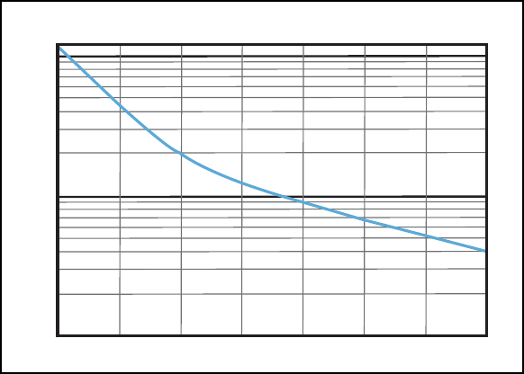
DOD is one of the main factors that determines how many cycles a battery can provide. The DOD is
simply the ratio of capacity extracted from the battery to its rated capacity expressed as a percentage.
Ifa100Ahbatterydelivers65Ahandisthenrecharged,itissaidtohavedelivereda65%DODcycle.
ThegeneralrelationshipbetweenDODandnumberofcyclesisshownbelowinFigure1.HigherDODs
results in longer cycle life.
TPPL Cycle Life Graph
10000
1000
100
Cycles
Depth of Discharge %
10 20 30 40 50 60
70
80
*Data based on laboratory testing
Figure 1
E . FLOAT APPLICATIONS
Batteries that are primarily used as a source of backup or emergency power are not frequently cycled.
The life of these types of applications is referred to as float life. Emergency lighting, security alarms
andUninterruptiblePowerSupply(UPS)aregoodexamplesofbatteriesinfloatapplications.In
eachoftheseapplicationsthebatteryisdischargedonlyifthemainutilitypowerislost;otherwise
the battery remains on continuous float or trickle charge.
Since ODYSSEY
®
AGM
2
batteries are dual purpose by design, they offer a long-life battery option in
float applications. At room temperature (77°F (25°C)), these batteries have a design life of 10+years in
float applications. At end of life, an AGM
2
battery will still deliver 80% of its rated capacity.
AMER-EN-IOM-ODY-0523
www.odysseybattery.com
10
F. CHARGING
TherelationshipbetweencyclelifeandDODshowninFigure1holdsonlyifthebatteryisproperly
charged after each discharge. This means that each time the battery is discharged, between
103-105%ofthedischargedamphoursshouldbereturned.Forexample,if100amp-hourswere
dischargedfromthebatterybetween103-105amp-hoursmustbereturnedtothebatteryforafull
recharge. Failure to do so (over or under charging) will result in a loss of cycle life and ultimately a loss
of capacity. There are several ways to recharge batteries and the best way depends on how the
battery is being used.
Charging with an Alternator
Whenusedinstartingapplications,ODYSSEY
®
AGM
2
12-voltbatterieswillbechargedon-boardwith
astandardautomotivealternatorthatgeneratesanywherebetween14.2-14.5voltsat77ºF(25ºC).We
recommendatemperaturecompensationofthechargevoltageat±18mvperbatteryperºCvariation
intemperaturefrom25ºC.Thewarmerthetemperaturethelowerthechargevoltageandthecooler
the temperature the higher the charge voltage.
Charging with an A/C Powered Charger
Whenusedincyclingorstand-bypowerapplications,anA/Cpoweredchargercanbeusedto
recharge ODYSSEY AGM
2
batteries. There are two main types of A/C powered battery chargers on
the market: full recharging ability or maintaining a full SOC.
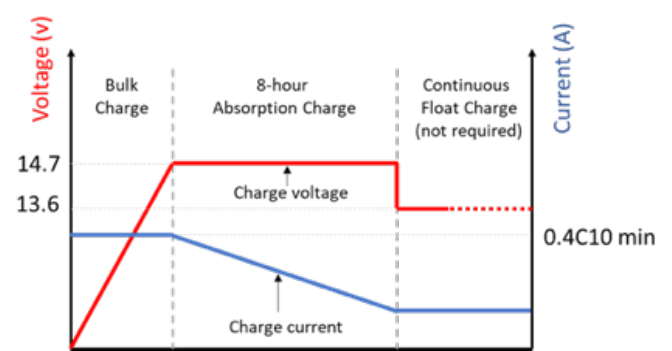
Inordertorechargeabatterythathasbeendischarged,itisbesttouseanautomaticchargerwithan
AGM setting that has the appropriate charge voltage and current per recommendations. For optimum
charging,thecurrentoutputshouldatleast40%ofthebattery’sC10rating.Thismeansabatterythat
hasa10-hourratingof100amphoursshouldbechargedwith40amps.Chargecurrentshouldnever
belessthan10%ofthebattery’sC10rating.Voltageshigherthan15.0voltswillcauseirreversible
damage to the battery. Please refer to Figure 2 below for a graphical representation of the
recommended charge profile for ODYSSEY AGM
2
batteries used in non-starting applications.
Figure 2
ChargersthataredesignedformaintainingafullSOCareoftencalled“float”or“trickle”chargers
andgenerallysupplycurrentinthe0.5ampto1.5amprange.Thesechargersmightalsobecalled
maintenance chargers and are often used to maintain batteries that are used in seasonal applications
such as boats or RVs. These chargers are not suitable for recharging ODYSSEY AGM
2
batteries that
have been deeply discharged. However, they are suitable for maintaining batteries at a full SOC,
provided the float voltage setting is appropriate. The recommended float voltage for ODYSSEY AGM
2

11
AMER-EN-IOM-ODY-0523
www.odysseybattery.com
batteriesis13.6voltsfora12-voltbatteryat77°F(25°C).
There are also chargers available that charge using constant current. These chargers do not have
multiple charge phases as shown in Figure 2. They simply supply current to the battery, which causes
the battery voltage to rise. Once the battery voltage reaches the setpoint for a fully charged battery,
the charging will terminate. How long it takes to charge a battery with this method depends on how
deeplythebatteryisdischargedandhowmuchcurrentthechargerprovides.SeeTable6belowas
anexampleofrechargingabatteryratedat100Ahfromvariousdepthsofdischargeusinga10-amp
constant current charger.
Open Circuit
Voltage
Depth of Discharge Charge Time
(hours)
12.6 25% 4
12.2 50% 8
11.9 75% 12
11.5 0% 16
Table 6
Temperature Compensation of Charge Voltages
Proper charging of all AGM
2
batteries requires temperature compensation of the charge voltage. This
is especially true in float applications where the batteries are on-charge constantly. The temperature
compensationcoefficientisapproximately±18mVper°Cvariationfrom25°Cper12-voltbattery.
Temperature and charge voltage are inversely related. Therefore, charge voltage must be reduced as
temperatures increase and charge voltage must be increased as temperatures decrease. Regardless
oftemperature,theminimumchargevoltageis13.2voltsaslowervoltageswilldamagethebattery
grids and shorten life.
Recovering a Severely Discharged Battery
Many commercially available chargers must detect a certain minimum voltage for the charging process
tostart.Thisisacommonsafetyfeaturetopreventusinga12-voltchargerona6-voltbattery.
Chargers of this type are unable to charge a battery that has been severely over-discharged. For
example,a12-voltchargermightnotstartthechargingprocessifthebatteryconnectedtoithasan
OCVof5volts.Dependingonthesizeofthebattery,therearetwowaystotrytorecoverthebattery.
• Forbatteriesusedinstartingapplications,thealternatorcanbeusedtorechargethebatteryafter
jump-starting the battery to start the vehicle.
• Forbatteriesnotusedinstartingapplications,asecondbatterythatisknowntobeatahighSOC
can be connected to the discharged battery in parallel. Refer to Section IV, B (Battery Sketch 2)
fordetailsrelatedtoconnectingbatteriesinparallel.Oncethelowbattery’svoltagereaches11.5
volts, the batteries can be disconnected from each other. The standard A/C
charger normally used by the system can then be connected to the battery that needs to be
charged. Please refer to “Procedure to Recover Deeply Discharged ODYSSEY Batteries”found
on www.odysseybattery.com for more details.
Itisimportanttounderstandwhythebatterybecameover-discharged,sothesituationdoesnot
happen again. The most common reasons for batteries to be over-discharged are system issues
relatedtoparasiticloads(seepage13)ormalfunctioning/non-existentlowvoltagedisconnect
equipment.
AMER-EN-IOM-ODY-0523
www.odysseybattery.com
12
Unfortunately,thisrecoveryprocessisnotalwayssuccessful.Whenbatteriesareseverelydischarged,
sulfation develops and can be very difficult to remove depending on how deeply the batteries
are discharged and how long they have been in that state. This condition is not warrantable
since it is the result of abuse or neglect in the application, rather than a manufacturing defect.
Racing Vehicles Using Total Loss (No Alternator)
Standardautomotivetypechargersarenotdesignedtoreturn105-108%oftheenergyremoved.
Theynormallyboostchargeto80-95%andexpectthealternatortocompletethecharge.EnerSys
®
recommendsusingchargersthatprovide105-108%rechargebeforeswitchingtostoragecharge.
Chargers approved by EnerSys are listed on www.odysseybattery.com.
TofullychargeanODX-AGM31andODP-AGM31batterythatareroutinelydischargeddeeply,a
minimumof40ampsarerequiredwithchargervoltagewithintherangeof14.1voltsto14.7volts.
Itisimperativenottoexceed15.0Vasthiswillcausethepressurevalvestoopenandout-gas
hydrogen, oxygen and water from inside the battery. This will shorten the life of the battery and
causeprematurefailure.Someportablechargersexceed15.0volts,especiallytwo-wheelgarage
chargers,sochargingvoltagesshouldbeveriedbymeasuringthechargingvoltageduringthetime
when the charging amperage is reducing from full output. The deep cycle charging voltage must be
within14.1voltsminimumto14.7voltsmaximum.
Ifastandardautomotivechargerisusedtoboostchargeadischargedbatterybecauseofan
accessorylefton,itisimportanttomakesurethechargingvoltagedoesnotexceed15.0volts
during charge. A hand held voltmeter can be used to monitor this periodically.
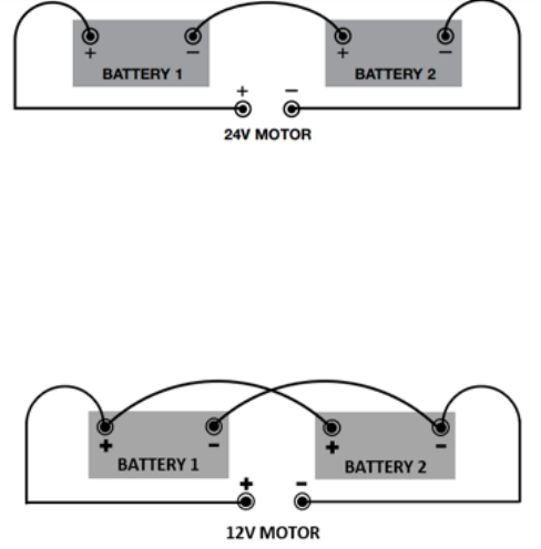
12V Parallel Connection
BATTERY 1
BATTERY 2
12V MOTOR
GROUND
VEHICLE &
CONNECTION
Battery Sketch 3
24V Parallel Connection
To power a 24-volt trolling motor, you will need to connect two ODYSSEY
®
batteries in a series. As
showninBatterySketch4,thenegativeofBattery1iswiredtothepositiveofBattery2.Hookupthe
positiveterminalofBattery1tothepositiveterminalofyourtrollingmotorandthenegativeterminalof
Battery 2 to the negative terminal of the trolling motor.
BATTERY 1
BATTERY 2
24V MOTOR
Battery Sketch 4
13
AMER-EN-IOM-ODY-0523
www.odysseybattery.com
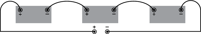
36V Parallel Connection
Topowera36-volttrollingmotor,youwillneedtoconnectthreeODYSSEYbatteriesinseries.As
showninBatterySketch5,thenegativeofBattery1iswiredtothepositiveofBattery2;thenegative
ofBattery2isthenconnectedtothepositiveofBattery3.Finally,hookupthepositiveterminalof
Battery1tothepositiveterminalofyourtrollingmotorandthenegativeterminalofBattery3tothe
negative terminal of the trolling motor.
BATTERY 2
36V MOTOR
BATTERY 3
BATTERY 1
Battery Sketch 5
G. PARASITIC LOADS
Inmanycasesbatteriesthatareapparentlyatrestmaybesupplyingasmallamountofcurrentto
connected equipment such as radios, clocks and security systems, to name just a few examples.
Today’svehicleshavemultipleon-boardelectronicsthatrequiresmallamountsofpower.Thesesmall
currents are collectively referred to as parasitic loads and may be detrimental to the life of a battery if
they are not accounted for in the design of the system.
Overtimethesesmallloads–typicallytensofmilliamps(mA)–willconsumesignificantamphours,
which results in the battery voltage decreasing. Consider a boat that has a parasitic draw of 20mA and
isdockedforfivemonthswiththebatteryconnectedtotheload.Inthat150-dayperiodthatparasitic
load will consume more than 70 amp hours.
There are three ways to ensure that batteries are not being drained by parasitic loads in the system.
1.Physicallydisconnectthebatteryfromtheloadafterfullychargingit.Amasterdisconnect
switch is also an effective countermeasure.
2. Periodically give the battery a freshening charge, using the charging guidelines outlined
onpage10.
3.ConnectatricklechargerforAGMbatterieswhenthebatteryisstored,usingthecharging
guidelinesoutlinedonpage10.
H. TESTING
There are several different ways to test AGM
2
batteries. Depending on the time and equipment
available, one may choose to perform either a capacity test, a ½CCA Load Test or a Conductance
Test. These options should help determine whether the battery returned by the customer has reached
its end of life or simply needs a full recharge. For all methods, the battery should be fully-charged
before testing. The following includes details related to each test method:
RECOMMENDATION: Testing should be completed on a clean/main battery terminal surface, not
a steel stud. Testing batteries individually in multiple battery situations is best. At minimum, each
battery must be disconnected at one terminal (the same polarity).
1. Capacity Testing: This method tests the performance of the battery based on its Reserve
Capacity (RC) rating, which means the test may be more time consuming, however it is the
preferred test method for a state of health check. The equipment needed to perform this

AMER-EN-IOM-ODY-0523
www.odysseybattery.com
14
type of testing is called a discharger tester. The battery should be fully charged before using
this test method. Discharge testers are designed to apply a constant current load to a fully-
charged batteryuntilthebatteryvoltagereaches1.75voltspercell(10.5voltsperbattery)or
other appropriate end point voltageinlinewithpublishedperformancetables,whichis100%
discharged.Thelengthoftimethedischargetesterrunsuntil1.75voltspercellisreached
shouldbecomparedtothebattery’srated RC. Batteries that do not provide at least 80% of
their rated runtime are considered failed.
2. ½CCA Load Test: This method tests the performance of the battery based on its CCA rating
and is much faster than capacity testing. The equipment needed to perform this type of test is
called a ½CCA load tester. For accurate testing, the battery must be at least 75% charged,
which for AGM
2
batteriesmeanshavinganOCVof12.6voltsorhigher.
To perform the test, the CCA rating of the battery must be programmed into the tester. These
testersapplyhalfofthebattery’sCCAratingtothebatteryfor15seconds.After15seconds,
thebatteryvoltageshouldbeabove9.6voltsifthetemperatureis70°F(21°C)orwarmer;voltage
below 9.6indicatesafailedbattery.Fortemperaturesbelow70°F(21°C), refer to Table 7 on the
next page for voltage. Most of these testers will specify whether the battery passed or failed the
test. This can be an ideal test for batteries used in starter applications.
Temperature End of Test Voltage
70°F(21ºC) 9.60
60°F(16ºC) 9.50
50°F(10ºC) 9.40
40°F(5ºC) 9.30
30°F(-1ºC) 9.10
20°F(-7ºC) 8.90
10°F(-12ºC) 8.70
0°F(-18ºC) 8.50
Table 7
3.Conductance Test: This method tests the performance of the battery based on its level of
conductance. This is a fast test and is generally the type of test that will be used by auto parts
shops. The equipment needed to perform this type of test is a hand-held electronic battery
tester. There are a variety of hand-held testers on the market and most allow the user to
programkeybatteryparameterssuchasCCAandbatterytype.Ifthetesterhasanoptionfor
AGM
2
, it should be used, otherwise AGM is suitable. Like the ½CCA Load Test, the AGM
2
batteryshouldhaveanOCVof12.6voltsorhigherbeforetesting.Aftertheelectronictestingis
complete, the tester will indicate whether the battery passed or failed.
I. MAINTENANCE
ODYSSEY
®
AGM
2
batteries are very different from standard flooded batteries that are openly vented.
These batteries operate as a sealed battery, which depend on internal recombination of battery
gasses under normal operating conditions. This means that there should be minimal corrosion of
terminalsoranypartofthesurroundingarea.Intheeventthatcorrosionispresent,itisbesttoclean
it off thoroughly by using a wire brush on any metal surfaces, and a wet rag anywhere else where there
areresidualsubstances.Itisalwaysrecommendedtouserubbergloveswhencleaningabattery.Do
not use chemicals to clean a battery, as some can damage to the plastic of the battery. There is no
15
AMER-EN-IOM-ODY-0523
www.odysseybattery.com
need to add water to the batteries. Opening the battery cover causes damage to the battery and voids
any warranty.
PLEASE NOTE: Perform periodic inspection for case damage, loose battery hold downs, loose
connections, corrosion and container swelling.
J. VENTILATION
ODYSSEY
®
AGM
2
batteries are part of a broader category of lead acid batteries called VRLA. This type
of battery depends on the internal recombination of battery gasses for proper operation. The internal
valveallowsfornearly100%recombinationofgasses,whichmeansthereisnoneedtoperiodically
add water.
WARNING: Any battery producing an odor or visibly venting should be removed from service.
Physically disconnect only after the area has been ventilated.
The high recombination efficiency of ODYSSEY AGM
2
batteries makes them safe for installation in
humanenvironments.Itisnotuncommontoseethesebatteriesinaircraft,hospitaloperatingrooms
and computer rooms. The only requirement is that these batteries must not be stored, operated or
charged in a sealed or gastight enclosure. However, local regulations regarding ventilation must also
be followed.
K. Winter Storage
The ODYSSEY battery does not lose its charged energy during cold storage temperatures, so there
isnoneedtotrickleoroatchargeduringwintermonths.Tostoreo-season,measurethebattery
voltagetomakesureitisfullycharged,12.84voltsorgreater;rechargeifnecessary.Disconnectthe
negative battery cable to prevent any applied electrical load during storage. The ODYSSEY battery
cannotfreezedownto-40°F(-40°C),soitcanbeleftinthevehicle.Itcanbestoredfortwoyearsor
morebelow77°F(25°C).Chargingisrequiredattwoyearsor12.2volts,whichevercomesrst.
A12-volttricklechargercanalsobeleftconnectedtothebatteryifitiskeptinstorageforextended
periods or if the battery is subject to parasitic loads during storage. The trickle charge voltage
measuredatthebatteryterminalsmustbebetween13.5voltsand13.8volts.Itisrecommendedto
use the ODYSSEY battery charger for your battery. Additional information on ODYSSEY battery
chargers, where to buy ODYSSEY battery chargers and ODYSSEY battery charging in general can
be found at www.odysseybattery.com.
L. WARRANTY CONSIDERATIONS
ODYSSEY AGM
2
batteries are covered by warranty against defects in material and workmanship for at
least two years. Some models and applications are covered for longer. Please note that the following
actions will void any warranty coverage:
• Removingthelabeledcover
• Removingoralteringthebattery’sdatecode/serialnumber
• Removingoralteringthebatteryterminal(s)
• Openingthebatterycase
The complete warranty statement can be found on our website, www.odysseybattery.com, for more details.
AMER-EN-IOM-ODY-0523
www.odysseybattery.com
16
VI. ADDITIONAL INFORMATION
Should you need additional information, please contact your local Sales Representative or battery
supplier.OurTechnicalSupportgroupisalsoavailablebyphoneat+1-800-964-2837andby
submittingaTechnicalInquirythroughtheContactUslinkonourwebsite.
VII. FAQS
Are ODYSSEY
®
AGM
2
batteries the same as Gel batteries?
No, these are not Gel batteries. These are absorbed electrolyte batteries, which means there is no
freeacidinsidethebattery;alltheacidisabsorbedintheglassmatseparators.Theseseparators
servetokeepthepositiveandnegativeplatesapart.InGelbatteries,theelectrolyteisinagelform.
What is the Ah rating?
Theamperehour(Ah)ratingdefinesthecapacityofabattery.Abatteryratedat100Ahatthe
10-hourrateofdischargewilldeliver10Afor10hoursbeforetheterminalvoltagedropstoa
standardvaluesuchas10.5voltsfora12-voltbattery.
Does mishandling the battery void the warranty?
The warranty applies to manufacturing defects and workmanship issues and does not cover
damages caused by customer mishandling.
What is the CCA rating?
Per SAE standard, the Cold Cranking Ampere (CCA) rating is the number of amperes a battery can
deliverfor30secondsatatemperatureof0°F(-18°C)beforethevoltagedropsto1.2voltspercell
or7.2voltsfora12-voltbattery.A12-voltbatterythathasaratingof550CCAwilldeliver550amps
for30secondsat0°F(-18°C)beforethevoltagefallsto7.20.
What is the MCA rating?
The Marine Cranking Ampere (MCA) rating refers to the number of amperes a battery can deliver for
30secondsatatemperatureof32°F(0°C)untilthebatteryvoltagedropsto7.20fora12-volt
battery.A12-voltbatterythathasanMCAratingof725willdeliver725amperesfor30seconds
at32°F(0°C)beforethevoltagefallsto7.20.TheMCAissometimescalledthecrankingamperes
or CA.
What is the HCA rating?
TheabbreviationHCAstandsforHotCrankingAmps.ItisthesameasMCA,CAorCCA,except
thatthetemperatureatwhichthetestisconductedis80°F(26.7°C).
What is the PHCA rating?
UnlikeCCAandMCA,thePulseHotCrankingAmpere(PHCA)ratingdoesnothavean“official”
definition;however,itissuggestedthatfortrueautomotiveandmarinepurposes,a30-second
dischargeisunrealistic.ThePHCA,ashortduration(about3-5seconds)highratedischarge,ismore
realistic. Because the discharge is for such a short time, it is more like a pulse. The low impedance
of ODYSSEY battery technology allows them to maintain a higher voltage for more starter pulses,
resulting in less heating of starter motors and cables. Higher power output results in a faster start.
What is impedance?
The impedance of a battery is a measure of its internal resistance. The lower the battery impedance
the more the available power. The impedance of ODYSSEY
®
AGM
2
batteries is considerably
lower than that of a conventional automotive or marine battery. The high rate discharge capability
of ODYSSEY AGM
2
automotive and marine batteries is significantly higher than that of conventional
automotive and marine batteries.
17
AMER-EN-IOM-ODY-0523
www.odysseybattery.com
What is Reserve Capacity (RC) rating?
The RC of a battery is the number of minutes it can support a 25-ampere load at 80°F (27°C) before
itsvoltagedropsto10.50fora12-voltbattery.A12-voltbatterywithareservecapacityratingof100
willdeliver25ampsfor100minutesat80°F(27°C)beforeitsvoltagedropsto10.5.
What is the short-circuit current of these batteries?
Typically thousands of amps. As mentioned before, the AGM
2
batteries have a very low internal
resistance, which means that the short circuit current is very high. Precautions should be taken to
avoid short circuits as equipment and battery damage will occur.
What is the operating temperature range of these batteries?
Theoperatingrangevariesbasedonthebatterytype.RefertoTable3onpage8fordetails.
Is the battery ruined if it is dropped?
Itispossibletodamagetheinternalconnectionsaswellastheexternalcontainer,leadingtoa
damaged the battery. Batteries with visible external damage should not be used. Dropped batteries
should be tested prior to use.
VIII. DEFINITIONS OF ACRONYMS
AGM–AbsorbedGlassMatbattery.ThisisatypeofVRLAbatteryinwhichalltheelectrolyteinthe
battery is absorbed into the glass mat separator material.
TPPL – Thin Plate Pure Lead. This refers to the fact that these batteries are made of very thin plates,
which do not contain any calcium or other typical impurities that deplete battery voltage over time.
VRLA Battery – Valve Regulated Lead Acid Battery. These lead acid batteries are designed to include
pressurereliefvalvesthatallowfornearly100%recombinationofthegassesthatwouldventin
traditional flooded batteries. Because of this very efficient recombination process, there is no need
to periodically add water to these batteries.
OCV – Open Circuit Voltage. This is a voltage reading obtained from a battery that is not charging or
discharging. To get an accurate OCV on AGM
2
batteries, it is important to wait at least four hours after
chargingor30minutesafterdischargingtotakethevoltagereading.
DOD – Depth of Discharge. This is the measure of how many amp hours were taken out of a battery
comparedtothebattery’srating.Forexample,a100amp-hourbattery,whichhas40amp-hours
removed during discharge is said to be at 40% DOD.
SOC – State of Charge.Thelevelofchargeofabattery.Itcanbeapproximatedbyevaluatingthe
battery’sOCV.

www.enersys.com
EnerSys World Headquarters
2366 Bernville Road
Reading, PA 19605, USA
Tel: +1-800-964-2837
EnerSys EMEA
EH Europe GmbH
Baarerstrasse 18
6300 Zug, Switzerland
EnerSys Asia
152 Beach Road
#11-08 Gateway East Building
Singapore 189721
Tel: +65 6431 3700
© 2023 EnerSys. All rights reserved. Trademarks and logos are the property of EnerSys and its affiliates unless otherwise noted. Subject to revisions without prior notice. E.&O.E.
AMER-EN-IOM-ODY-0523
Want more info?
Scan code to access
the ODYSSEY
®
Battery
Literature Library
