
Table of
Contents
2 Think Like an
Engineer
3 LIGHT THE LAMP
4 It's Electric
9 The Electric
Playground
14 The Starting
Line Up
18 Drawing It Up
22 The Challenge
24 First Flight
Field Trip
Souvenir
Order Form
© 2020 Anaheim Ducks. All rights reserved. Reproduction in whole or in part
without written consent from the Anaheim Ducks is expressly prohibited.
There's nothing more exciting than a goal scored by the home team. When the
Ducks score you better be ready for something special to happen at Honda Center.
A horn fills the arena with sound, a goal song blasts from speakers throughout the
building, and intense red light flashes behind the goal. This electrifying event is known
to Ducks players and fans as "Lighting the Lamp". While the puck entering the net sets
off this chain of events, it's electricity, shooting through a vast series of circuits, that
makes it all happen.
You probably already know this but, electricity makes a lot of the things we do each day
possible. It powers the lights in our homes and the mobile devices we use to play the
newest games or to say "Hey!" to a friend. Electricity can be found almost everywhere
and Honda Center is no exception. We want you know how it works and to do so, you'll
go on a journey to light your lamp. The information in this workbook will teach you to
think like an electrical engineer. By the end of this book you'll design and build a circuit
that powers a light and sets off sound just like an Anaheim Ducks goal.
It will take your best effort and some perseverance to work through this book, not to
mention teamwork. But, once you do, you'll be ready to take on the challenges that await
you during the First Flight Field Trip. When it comes to hockey, the best goals take
teamwork, hard work, creativity, and skill.
Do you have what it takes
to "Light the Lamp"?
We know you do!
We can't wait to see
you March 9th.
Let's get started!
Dedicated to J.H.
2
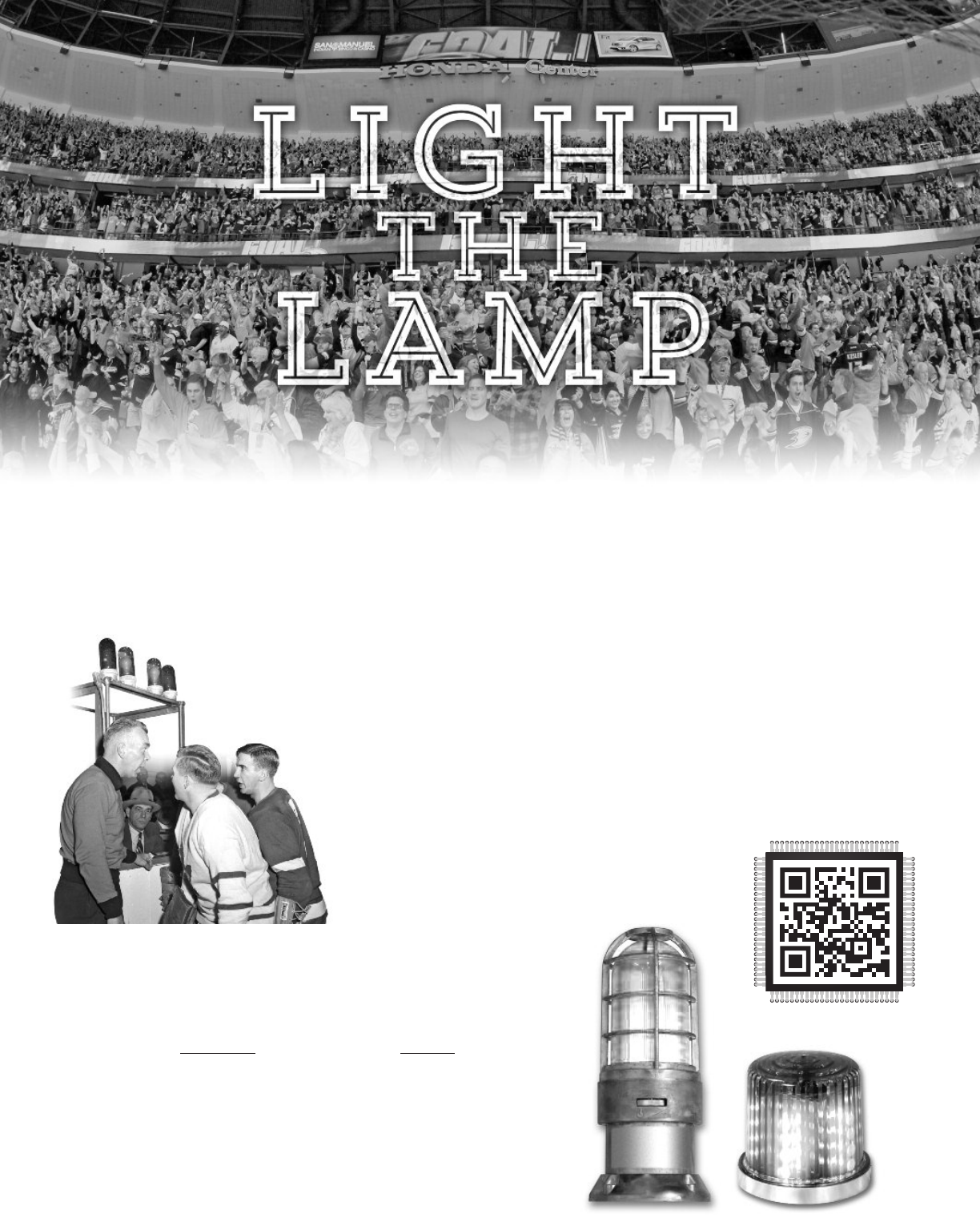
The term Light the Lamp has been used in hockey ever since the early days of the game. When it became a
spectator sport back in the early 1900’s, Light the Lamp had a very different meaning because electricity
wasn’t available everywhere as it is now. NHL arenas didn’t have access to lasers or smoke machines, nor did
they have fog horns or goal songs blasting through the speakers. What they did have was a lamp installed
behind the goaltender. This light was controlled by a goal judge who would turn it on only after the puck had
gone past the goaltender, crossed the goal line, and entered the goal. A flashing red light would indicate to
everyone in the arena that a goal had been scored!
Today, Light the Lamp is the event that fans look forward to when they attend a hockey game.
Why? Because it’s a celebration for a home team goal! At the heart of this celebration is
still a red lamp controlled by a goal judge. But now, there’s a whole lot more! A multitude of
flashing lights and sounds are also used to give fans more reasons to scream, shout, and sing
in response to their team’s accomplishment on the ice.
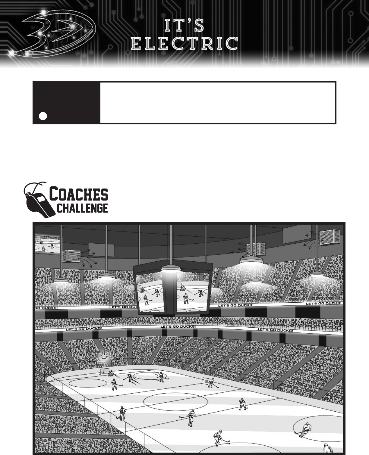
All 31 teams across the league Light the Lamp in their own creative ways.
The Calgary Flames fill the arena with red lights. The Columbus Blue Jackets
shoot cannons. And, the Edmonton Oilers blow fire out of an oil rig up in the
rafters. Just about every fog horn, every goal song,
and every red lamp is unique. When the Anaheim
Ducks score a goal, a loud siren, fog horn, and laser
light show fill Honda Center. If you’re a Ducks fan,
this is the best thing in hockey!
Hockey often uses technology to improve the game for its fans.
From hockey sticks to the ways people can interact with players
using social media, lighting the lamp is no different. So, what
will Light the Lamp look like in the future? The possibilities are
limitless! Regardless, every light and every sound will still be
powered by electricity
and connected by circuits. It’s time to
learn about these things because you are the engineer we need
to improve this important aspect of the game. How will you use
your creativity to Light the Lamp?
THIS IS YOUR INVITATION TO INNOVATE!
2
LAMP HISTORY
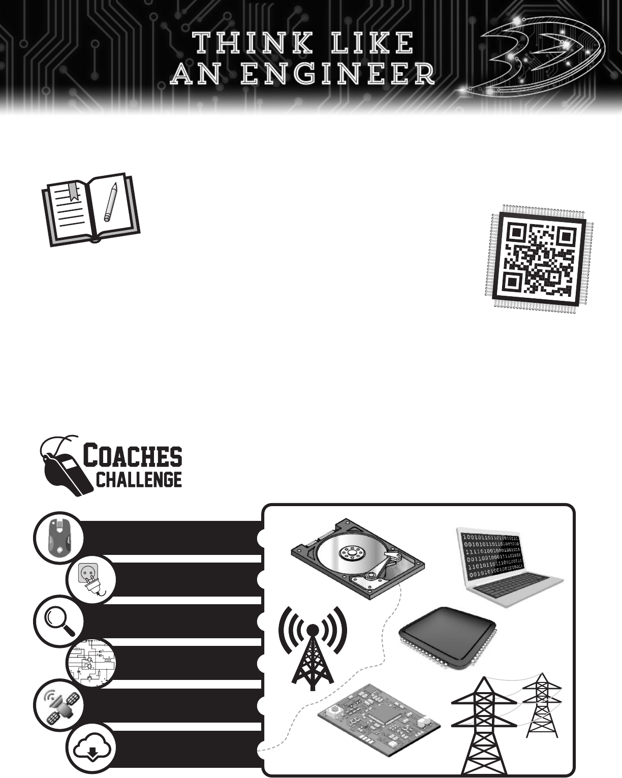
Power Engineer
Microelectronics Engineer
Circuits Engineer
Telecommunications Engineer
Information
Technology Engineer
Hard Drive
Circuit Board
Power
Line
3
Cell Phone
Tower
Compu
ter
Chip
Helmets are essential for the game of hockey. In order to think like
an engineer you’ll also need some equipment.
J
O
U
R
NAL
E
n
g
in
e
e
r
s
u
s
e
jo
u
r
n
a
ls
o
r
n
o
t
e
b
o
o
k
s
t
o
r
e
co
rd
t
h
e
ir
id
e
a
s
,
co
lle
c
t
e
d
d
a
t
a
a
n
d
c
a
lc
u
la
t
io
n
s
t
o
r
e
a
d
t
h
e
m
a
g
a
in
la
t
e
r
.
E
a
c
h
t
ime
y
o
u
s
e
e
t
h
is
ico
n
,
w
r
it
e
d
ow
n
s
o
me
n
o
t
e
s
o
r
a
ny
o
b
s
e
r
v
a
t
io
n
s
a
b
o
u
t
e
le
c
t
r
ic
it
y
in
y
o
u
r
jour
na
l. If
you
like
t
o
d
r
a
w,
ske
t
c
h
in
g
p
la
ns
a
nd
d
ia
g
ra
ms
is
encoura
g
ed
.
PE
N
C
IL
&
E
R
A
S
E
R
E
ng
ineer
s a
nd
sc
ientists li
k
e t
o
ta
k
e
no
t
es tha
t a
r
e ver
y
nea
t. T
ha
t
’
s wh
y
they
use p
enc
ils a
nd
e
r
a
ser
s fo
r
the
b
est r
esults. I
t
’
s imp
o
r
ta
nt t
o
k
e
ep
yo
ur
id
ea
s o
r
no
t
e
s, no
ma
tt
er
ho
w wild
a
nd
c
r
a
z
y
they
a
r
e
.
E
r
a
se mi
sta
k
es, no
t id
ea
s!
DON
’T HA
VE
A JOU
R
N
A
L
?
Scan the QR COD
E
and
find
the
P
ROJE
CTS
l
i
nk to
l
earn how to
mak
e one.
AVENGER OR ENGINEER?
The heroes and villains from the movies that take place in a galaxy far, far, away seem to use electricity with such
ease. They’re able to stop lightning bolts out of midair or even shoot them out of their fingertips. Although this
is make believe, there are in fact, real people who have the special ability to do amazing things with electricity.
Who are they? They’re electrical engineers! These men and women are behind countless everyday products and
are able to make our lives better by harnessing the power of electricity. They can control it to turn motors, send
digital messages through the air, and do thousands of other cool things. Most of all, we’re fortunate that these
engineers use their “powers” to turn on millions of light bulbs, keeping us out of the dark… side.
There are many types of electrical engineers, each specializing in using electricity
for good. Match the objects in the box to the engineer who most likely built it. Use
a dictionary or books on this topic to help you complete this activity! Then, in a
journal, write down the type of electrical engineer that interests you the most.
JOURN
A
L
C
o
m
pute
r
Computer Engineer
The atmosphere at a Ducks game is exciting. You can say that it’s electric! Electricity is exciting too. That’s
because life as we know it would be very different without this important resource. It keeps our homes warm
in the winter and cool in the summer. It allows us to do the many things that we love to do each day. Can
you imagine a world where we wouldn’t be able to turn on a light, car, or computer? We can’t either. That’s
why electrical engineers have worked really hard to make electricity available to us no matter where we’re
at. Whether we’re at home, school, or even at Honda Center, we are able to use electricity!
Take a look at Honda Center and circle as many things in the picture that
use electricity. In your journal, write down how you think electricity makes
these things work at this hockey game.
READ
THIS
FIRST!
!
All the experiments in this workbook use safe, low-voltage batteries and should
be done with adult supervision. PLEASE DO NOT use electricity from a wall
outlet for any of these activities. This type of electricity is high voltage that
could cause serious injury. Let’s respect electricity so that we can have a fun
and safe time Lighting the Lamp!
4
We hardly ever think about electricity beyond the outlets that we plug our devices into. So where does it
come from? Sure, it comes from a network of power lines leading to water, coal, or solar power plants.
But if we dig a little deeper, the truth is that electricity has always been around because it naturally exists
in the world. Have you ever seen lightning during a thunderstorm? That’s electricity! Electric eels have the
natural ability to shock their predators. Inside each one of us, electricity is used to send and receive signals
throughout our body’s nervous system. When you stub your toe, electricity carries the message of pain all
the way to your brain and then to your mouth to say “Ouch!”
It was just a little over 100 years ago that scientists figured out the nature of electricity. Most importantly,
they learned how to control it. These really smart people found that the atom was behind this magic. Atoms
are everywhere and in everything. They are the small building blocks of life that are too
small to see with your eyes. With special equipment, you’ll find that they’re made
of even tinier things called protons, electrons, and neutrons. These teams of
particles have many different properties and their special relationship
with each other is what we use to make electricity work for us!
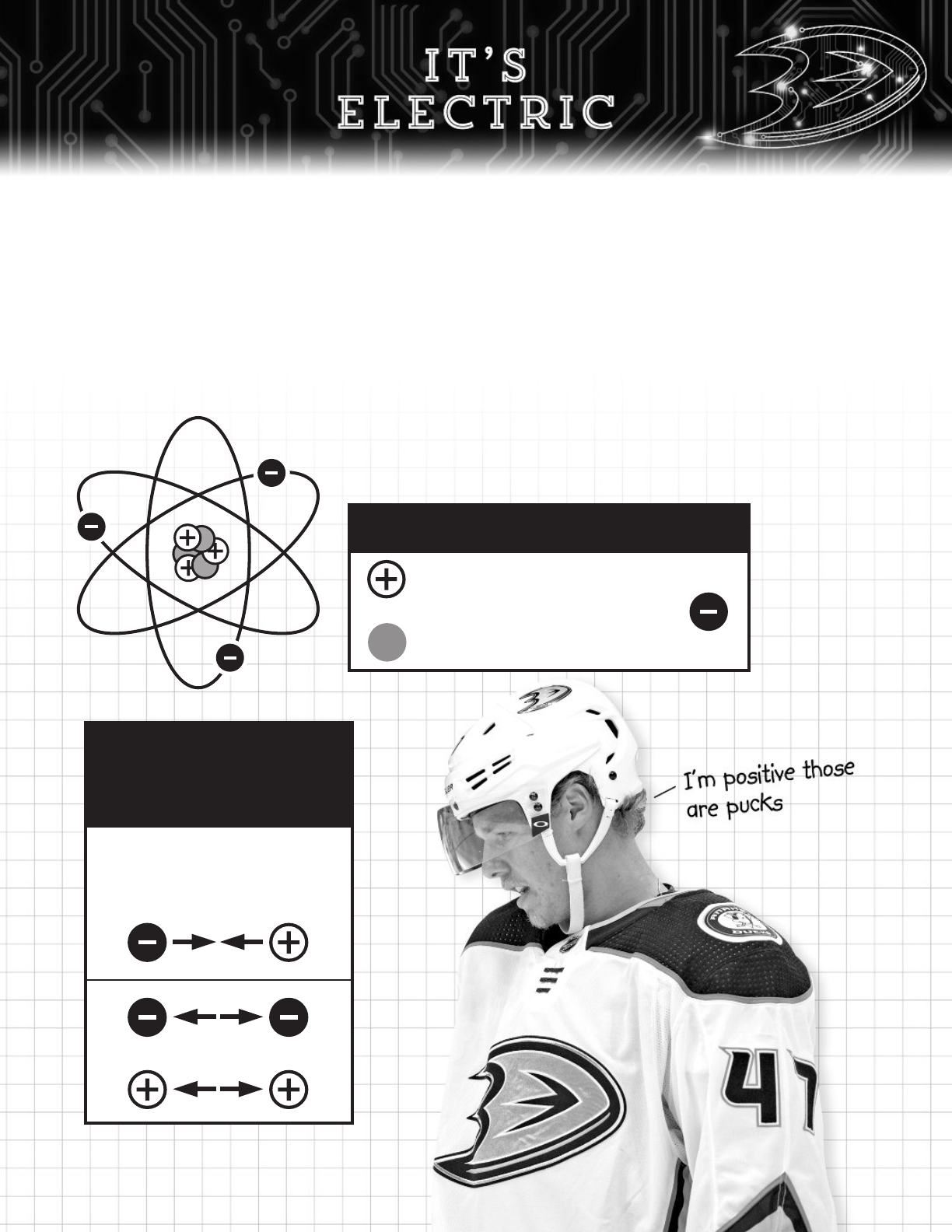
Protons and electrons each carry their own
type of electrical energy. This is called charge.
Protons have a positive (+) charge
Electrons have a negative (-) charge
Neutrons do not have a charge
Particles have a unique
relationship with each other.
There is an invisible (electric)
field that wants to keep them
together or apart!
Opposite charges are attracted
to each other. This is where the
phrase “opposites attract”
comes from!
Like charges repel
5
SPECIAL TEAMS
Objects around us are filled with millions, or even billions, of atomic particles. Most of the time, they are
neutral and contain an even number of protons and electrons. Neutral objects don’t have a charge because
the pluses (+) from the protons and the minuses (-) from the electrons cancel each other out like a simple
math problem. However, when particles become imbalanced, there’s a name for these special objects.
Objects with more electrons are negatively charged and those with more protons are positively charged.
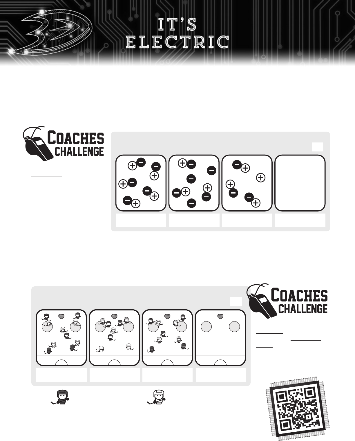
Take a look at the pictures
to the right and label each
cell positively charged,
negatively charged, or
neutral. Then, draw your
own picture using the
information that’s given
to you.
A hockey rink during an NHL game is filled with a lot of excitement as well as 40 players from a home team
and away team. But, only five skaters and one goalie from each team are allowed to be on the ice while the
others wait their turn on the bench. For most of the game, these teams play at even-strength. That’s when
the number of home team players on the ice are equal to the away team players. However, when penalties
are called, players are sent to the box for two or five minutes. There’s a name for these special teams. A
team with more players is on a power play and a team with fewer players is on the penalty kill.
Take a look at the pictures
to the left and write down
whether the home team
Ducks are on the power play,
penalty kill, or even strength.
Then, draw your own picture
using the information that’s
given to you.
Protons = 5
Electrons = 5
Protons = 3
Electrons = 6
Protons = 4
Electrons = 3
Protons = 8
Electrons =
Neutral
Ducks = 5
Sharks = 5
= Ducks (Home Team)
Ducks = 3
Sharks = 5
Ducks = 5
Sharks = 4
Ducks = 4
Sharks =
Power Play
= Sharks (Away Team)
6
POWER
PLAY
In hockey, moving the puck using the skill of passing often leads to speedy rushes up the ice or incredible
goals. This is the thing that Anaheim Ducks fans love to see. It’s no different with electricity. Amazing things
happen when electrons move. When they do, it generates two types of electricity - static electricity
and current electricity.
STATIC ELECTRICITY
Static electricity is a build-up of electrons on the surface of an object. Although this happens all around us,
we don’t realize it exists until we touch something made of metal. The shock you feel, hear, or even see is the
result of static electricity on your body. So how does this happen? The best way to explain this is through our
most common run-in with static electricity.
Static Electricity
by Adhesion
Electrons move by sticking onto
another object. When two neutral
objects are rubbed together,
electrons can break free from
one object and adhere, or stick,
to the other.
Static Electricity
by Conduction
Electrons move through touching.
The electrons from a negatively
charged object will disperse
all over a neutral object when
they touch.
Static Electricity
by Induction
Induction is the movement of
electrons by the repelling and
attracting nature of atomic
particles.
A
B
C
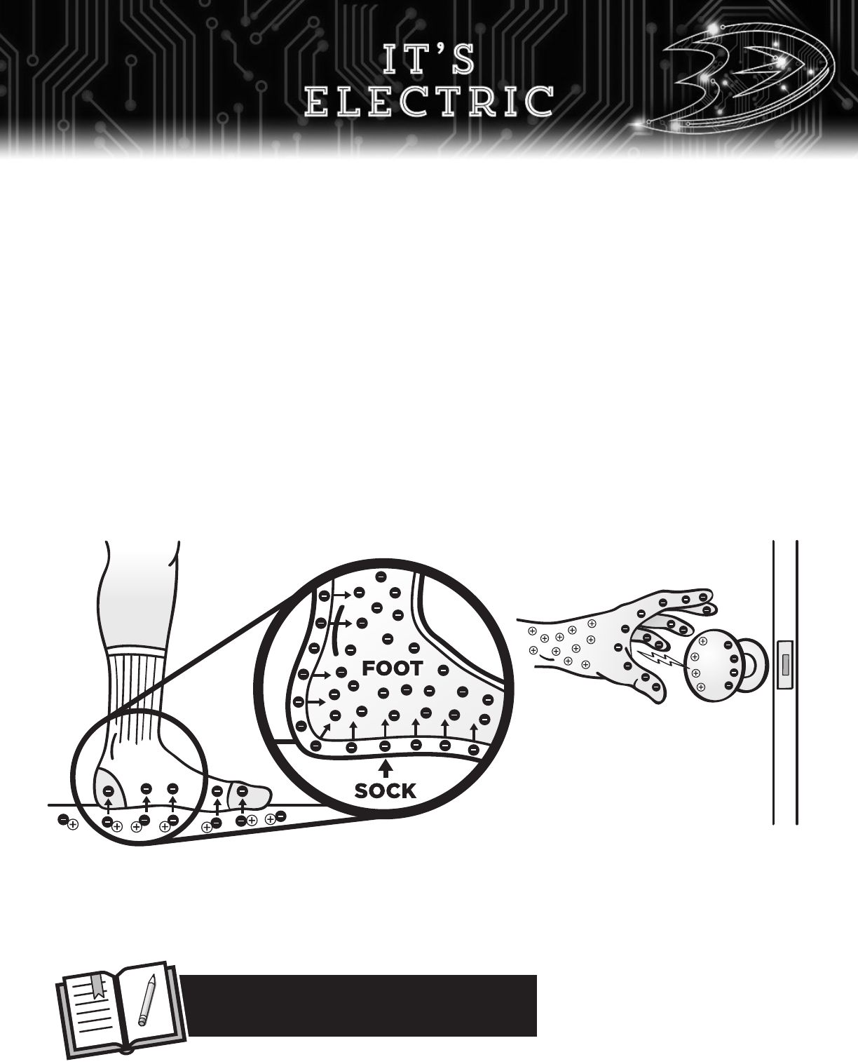
Walking over carpet is a perfect
example of this. Electrons from
the carpet stick to the sock each
time you take a step. Now you’ve
got a charged up sock!
Electrons move onto your skin
when it touches the sock. Now,
the entire surface of your skin is
negatively charged... all the way
out to your fingertips!
The electrons on your fingertips
repel the electrons and attract
the protons of the doorknob.
Because opposites attract, the
shock you feel when your hand
gets near the doorknob are
electrons jumping over to be
with their proton friends.
7
What other places have you observed static
electricity in your classroom or school?
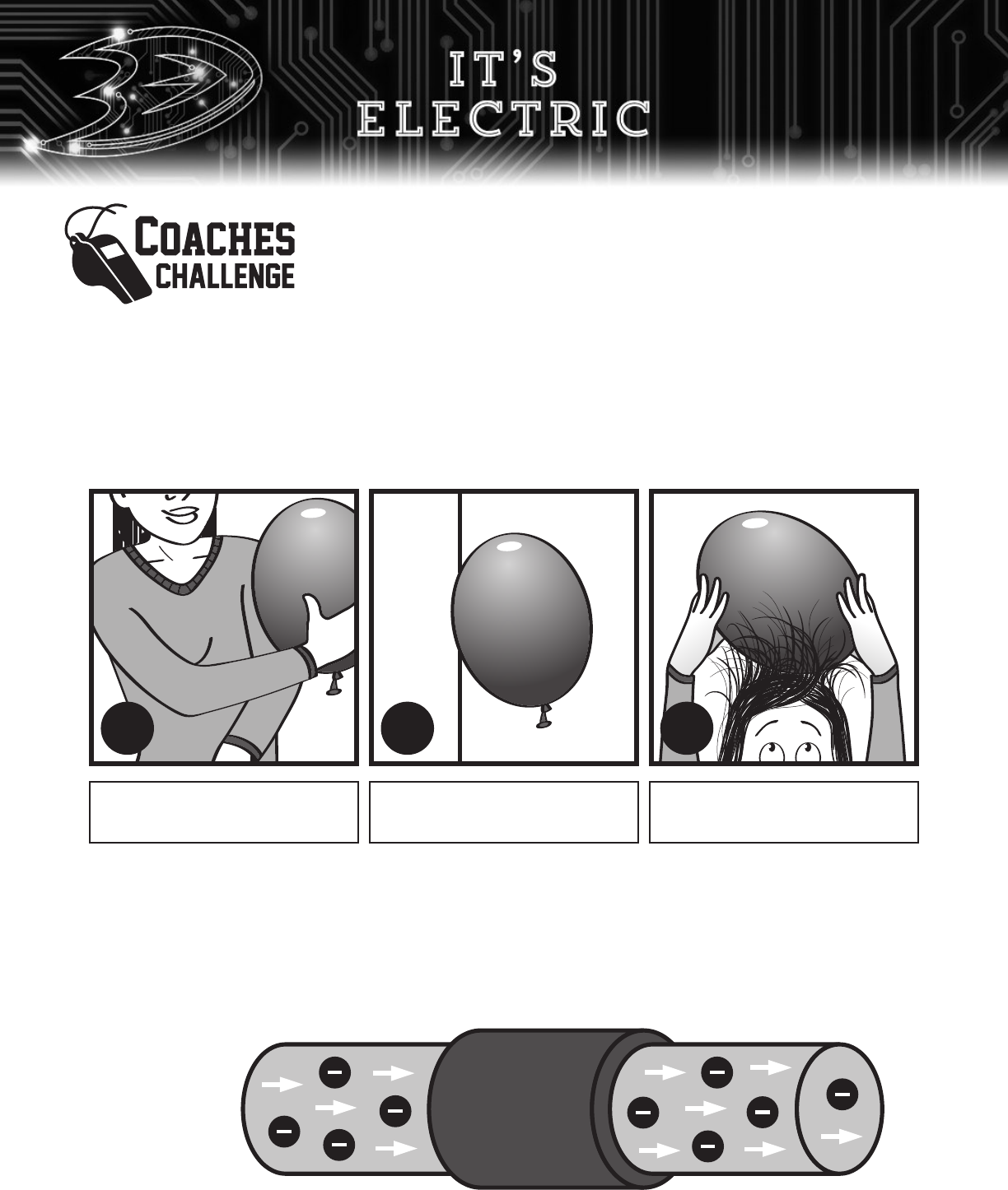
Complete the “hair raising” activities below to see, feel, and hear static
electricity at work.
Step 1: Gather Materials
• Blown up balloon
• Bed head
Step 2: Try the activities found in pictures A, B, and C. Start with A. Then, for B and C, you’ll need to
charge up the balloon first before doing these activities.
Step 3: Write your observations for each activity in the space provided or in your journal. How did
you experience static electricity and where did you see static electricity by adhesion,
conduction, and induction?
CURRENT ELECTRICITY
Static electricity goes away, or discharges, very quickly. While it can provide a large amount of electricity,
we need something else that can power the lights and our devices for long periods of time. Current
electricity is the answer! Current electricity is what you get when there’s a continuous, or non-stop, flow
of electrons through an object. Thanks to electrical engineers, we can create this flow of electrons using
generators that push them safely to people’s homes near and far. The best thing about current electricity
is that we can control it using a circuit, the electric playground for electrons!
The rate, or speed,
of electron flow
is measured in
amperes (A).
A B
C
8
Wall
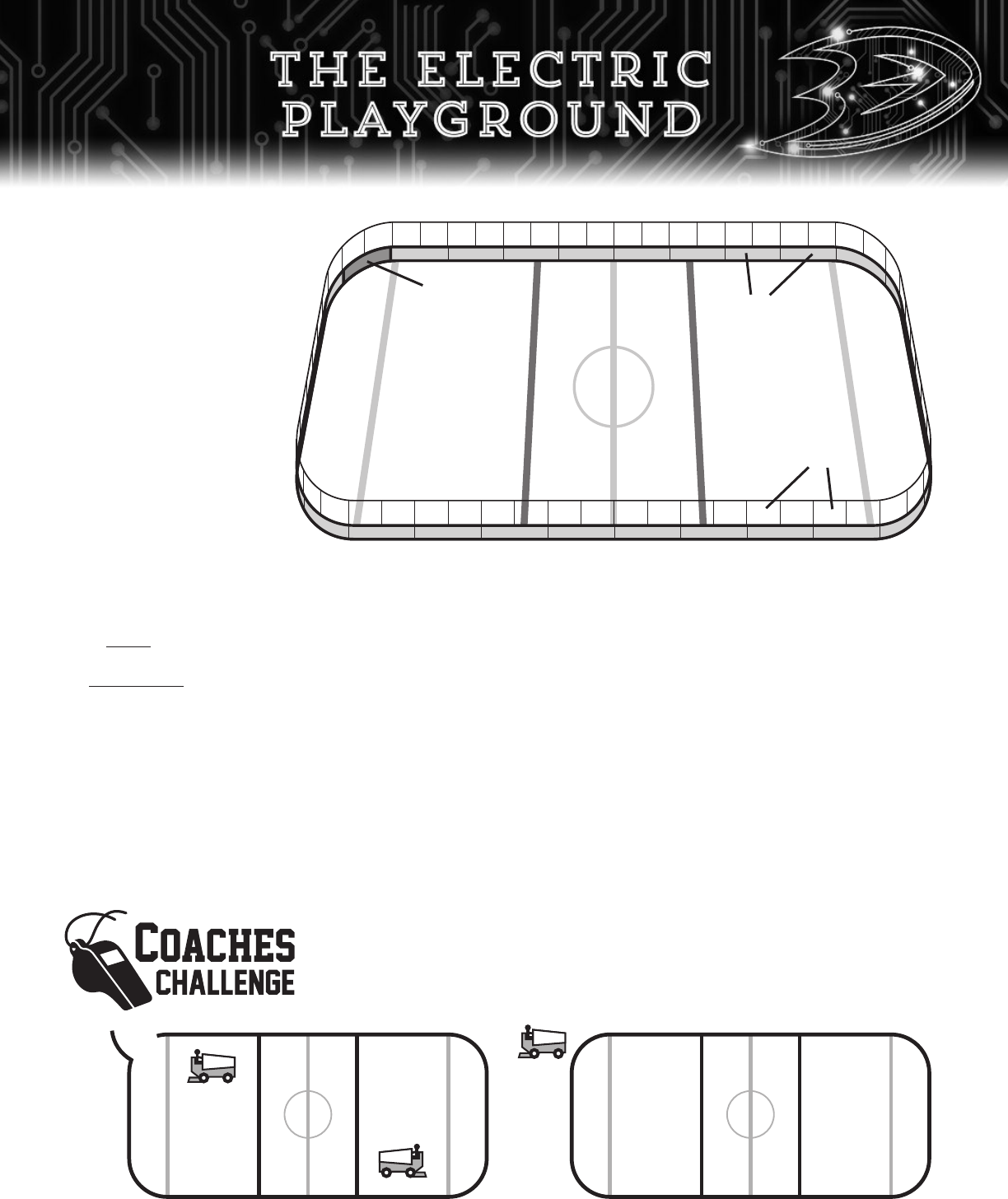
DASHERBOARD
A series of about 70 rink segments
called dasherboards are connected
side-by-side in the shape of a
hockey rink. Each one is 96 inches
long and 40 inches tall.
PLAYING SURFACE
This is the one-inch thick ice sheet
that makes up the foundation of
the ice rink. The parallel lines that
run across the width of an ice rink
divides it into three zones -
offensive, defensive, and neutral.
PROTECTIVE GLASS
A piece of half-inch thick
acrylic glass sits on top of
each dasherboard. They keep
the puck in play and protect
the fans from most slap shots
and high speed collisions.
MATERIAL
Dasherboards are made of a
durable but elastic material that
helps the puck keep its speed
each time it bounces off of the
rink walls.
ZAMBONI DOOR
This segment can be opened or
closed. When the door is open,
the large gap it creates allows the
Zamboni ice resurfacing machine
to enter the rink. The game can
only resume when the door is
closed. This completes the rink’s
shape again.
SHAPE
The ice rink is formed in a
complete loop and without any
gaps. Its shape keeps the puck
and players safely inside the rink.
THE ICE RINK
No other sport in the
world has anything like
the hockey rink. That’s
because no sport uses
an object as dynamic as
a hockey puck. From its
shape to the materials
it’s made of, everything
about the ice rink
was made for hockey.
It keeps the spectators
safe, allows for
physical play, and
most of all, it’s the place
where the puck can
move at a fast and exciting
pace. Let’s learn about the things that make up this frozen playground.
Identify the two types of ice rinks when the Zamboni door
is at positions A and B. Circle the correct answers below.
ZAMBONI
DOOR
PLAYING
SURFACE
DASHERBOARD
PROTECTIVE
GLASS
9
A
B
OPEN RINK or CLOSED RINK OPEN RINK or CLOSED RINK
The electron is an atom’s most dynamic particle because it loves to move! But, it’s not until they all flow in
one direction in a circuit does it become electricity we can use. From its shape to the materials it’s made
of, everything about a circuit is amazing. It gives electrons a path to follow and it connects components
together so that we can do fun and
exciting things with them. Let’s learn
more about the things that make
up this electric playground!
THE CIRCUIT BOARD
Circuits can be found inside any
item that requires electricity. They
can be found in simple items like
flashlights or very complex ones
like computers. No matter what
they look like, all circuits share
the same basic rules. That
includes the circuit that Lights the
Lamp at Honda Center! The best
way to learn about these rules is to
start with a working circuit and then
learn about the parts that form it. This type of backwards engineering has a name.
It’s called reverse engineering. Let’s engineer and reverse engineer your circuit!
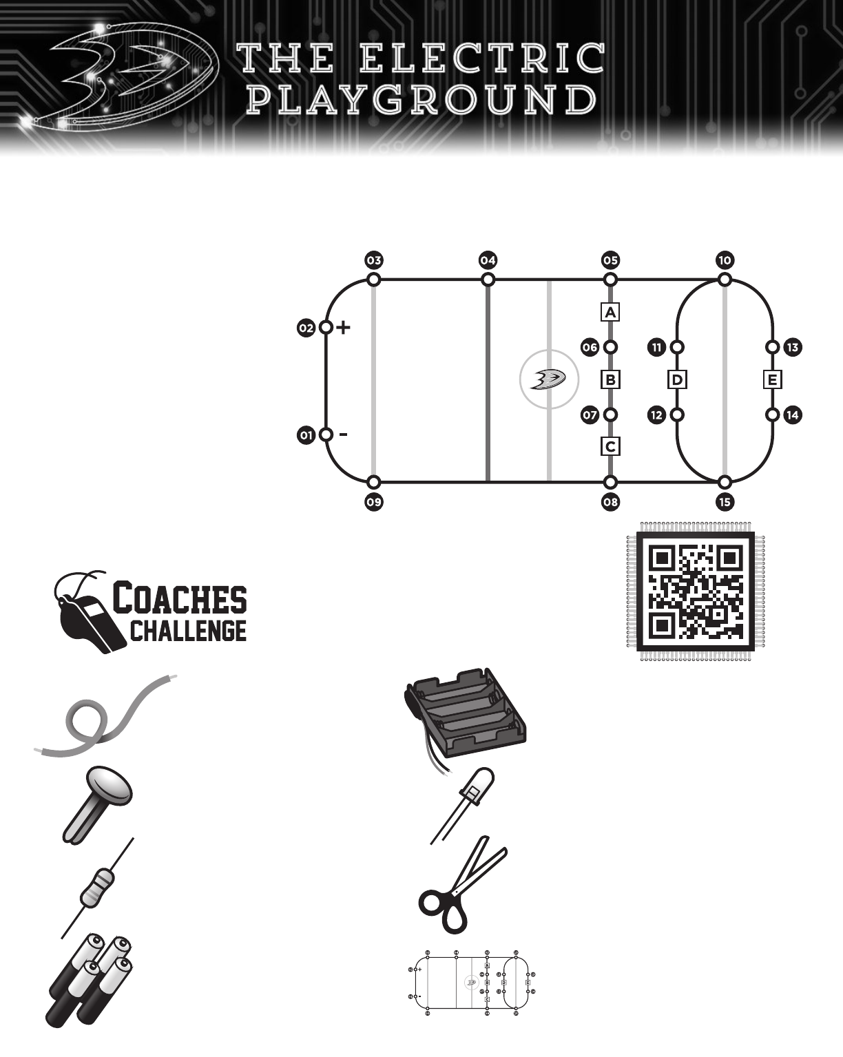
Step 1: Gather Your Materials
You’ll need the following materials to engineer the
Light the Lamp circuit. Before you get started, how
do you think each item will be used?
Battery
Holder _________________________
_________________________________
Red LED Bulb ______________________
_________________________________
Scissors __________________________
_________________________________
Light the Lamp
Circuit Board __________________
________________________________
Orange Wire _______________________
_________________________________
9 Brass Fasteners ___________________
_________________________________
220Ω Resistor
(red, red, black, black, brown) ___________
_________________________________
Four (4) AAA Batteries ________________
_________________________________
+
-
+
-
10
CIRCUIT
Step 2: Attach Your Materials to the Circuit Board
Follow the instructions below to attach the battery, wire, resistor, and red LED using the terminals (or
holes) numbered 01 to 09.
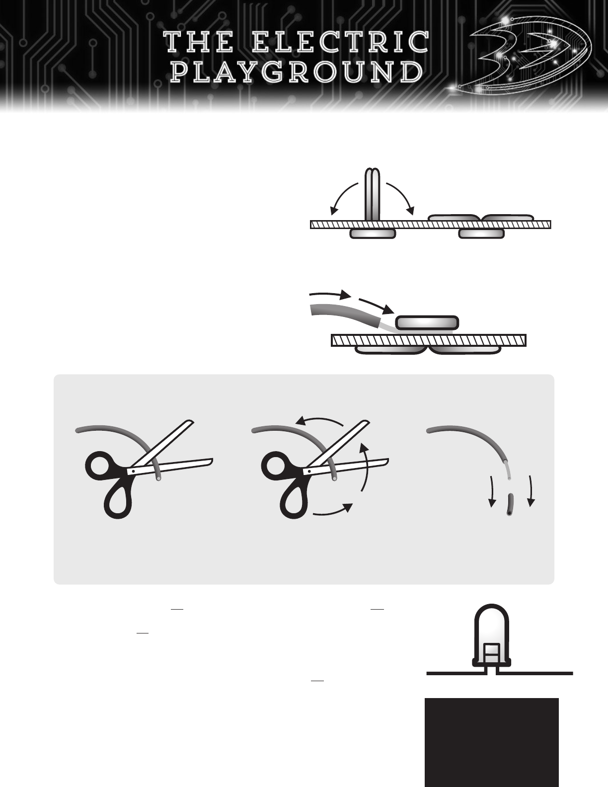
Stripping a Wire
There are fancy tools you can use to “strip” a wire but a pair of scissors will do the trick!
B. Wires @ segments [02-03], [04 -05], [05-06], [07-08], [08-09], and [01-09]
• Measure the distance between the terminals and then add an inch to it before
cutting each wire segment.
• Use scissors to remove the outer jacket from
both ends of the wire. Read the box below to
learn how to do this!
• Insert, or hook, each metal end of the wire under
the heads of the brass fastener. Push it from
underneath the board to make space for the wire.
Step 1: Open your scissors and
slide the wire about an inch
through the place where the
blades cross.
Step 2: Squeeze the scissors gently.
Then, rotate it around the wire a few
times or until you can see the metal
center. Be careful not to cut the wire!
Step 3: Pull off the
insulating jacket with
your fingers. You’ve
done it!
C. Battery Holder @ [01-02
]
• Insert the black wire (-) at 01 and the
red wire (+) at 02.
• Don’t insert the batteries yet!
D. Resistor @ [03-04]
• Insert the ends of the resistor at 03 and 04.
E. LED bulb @ B [06
-07]
• Bend the leads gently until
they run flat.
• Mark the longer lead with
a black pen.
• Insert the longer lead (+)
at 06 and the shorter
lead (-) at 07.
Step 3: Power it UP!
• Insert four batteries into the battery holder and watch the LED light up!
A. Terminals @ 01, 02, 03, 04, 05, 06, 07, 08, and 09
• A terminal is the place where wires and components
connect. Push a brass fastener through the holes
numbered 01 to 09 and bend the tails on the other
side of the circuit board to secure them tightly.
+
-
11
Remove batteries
from holder
whenever you’re
done engineering.
SHAPE
In order for electrons to flow, it needs a path to follow. That’s why a basic circuit is formed like a hockey rink.
It’s a closed loop without any gaps or breaks. But when the segments that make up a circuit stop touching,
electrons will stop flowing. This is called a break in the circuit. Not all breaks are bad though. Have you ever
been told by an adult to turn off the lights? If so, you’ve broken a circuit using a light switch before.
Whether it’s a push, pull, or flip, a switch works very much like a Zamboni door because it involves opening
and closing a loop for a reason. An open switch usually turns a device off because it creates an open circuit.
Closing a switch turns a device on. It forms a closed circuit so that electrons can flow again.
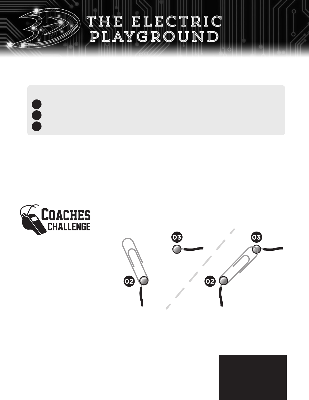
Questions:
1. Which of the following
circuits did you form with the
paper clip at position A?
Circle the answer below.
OPEN
CIRCUIT
CLOSED
CIRCUIT
or
2. What will happen to the LED when you move the paper clip
to position B? Explain.
__________________________________________________________
__________________________________________________________
___________________________________
___________________________________
___________________________________
It’s time to add a circuit’s version of a Zamboni door to this electric playground.
But first, make sure your basic circuit is assembled without
any batteries in the
battery holder.
Step 1: Find a small paper clip.
Step 2: Remove the brass fastener
completely at 02 and the
wire at [02-03].
Step 3: Insert the brass fastener
through one end of the paper
clip and push it back into the
circuit board at 02. Move the
paper clip to position A.
Step 4: Insert four batteries into
the battery holder.
A basic circuit consists of the following:
The right shape and materials for electrons to flow through.
A power source that provides the energy to create electron flow.
Other components that turn electron flow into light, heat, motion, and sound.
2
3
Congratulations! You just built your first basic circuit. In order to build bigger and more complex ones, you’ll
need to learn more about the following parts and the rules for forming a circuit. We’re off to a great start!
1
Position
A
Position
B
12
Remove batteries
from holder
whenever you’re
done engineering.
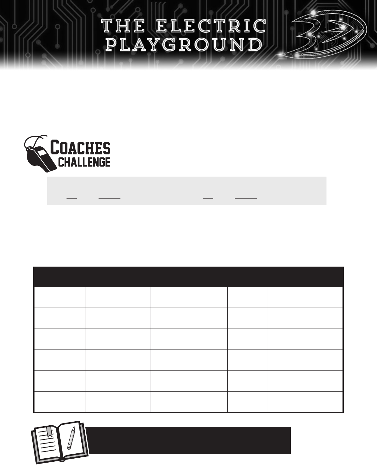
Object (A) Material (B)
Prediction (C) LED (D) Results (E)
(circle one) (circle one) (circle one)
Paper Clip Conductor or Insulator ON or OFF Conductor or Insulator
Rubber Band Conductor or Insulator ON or OFF Conductor or Insulator
Pencil Conductor or Insulator ON or OFF Conductor or Insulator
Quarter Conductor or Insulator ON or OFF Conductor or Insulator
Yarn or String Conductor or Insulator ON or OFF Conductor or Insulator
Aluminum Foil Conductor or Insulator ON or OFF Conductor or Insulator
MATERIALS
Circuits must be made of the right materials to give electrons the best chance of flowing through it. That’s why
conductors are often used to form circuits. They’re a highway for negative charge! Insulators, on the other
hand, are often used as a barrier to prevent electrons from flowing to other conductors. Did you know that you
can be a conductor if the electricity is strong enough? The rubber layer around an electrical cord is used to keep
people, like you, safe from injury.
There are many objects around the house or classroom that are great conductors
and insulators. Are you ready to identify them with your circuit? Complete the
following sentence before starting this activity!
A circuit made of insulators
will (or) will not light the lamp.
A circuit made of conductors
will (or) will not light the lamp.
Step 1: With your circuit built and batteries installed,
keep your switch in the OPEN position.
Step 2: Gather the objects from column A in the
chart below.
Step 3: Complete columns B and C for your first object.
Write down what it’s made of and predict
whether it is a conductor or insulator.
Step 4: Place the first object onto the brass
fasteners at 02 and 03. Make sure they
touch both terminals. Did the LED turn on?
Update columns D and E.
Step 5: Repeat step 4 for the rest of the objects.
13
Look around your classroom. List five (5) other objects you
think conduct electricity.
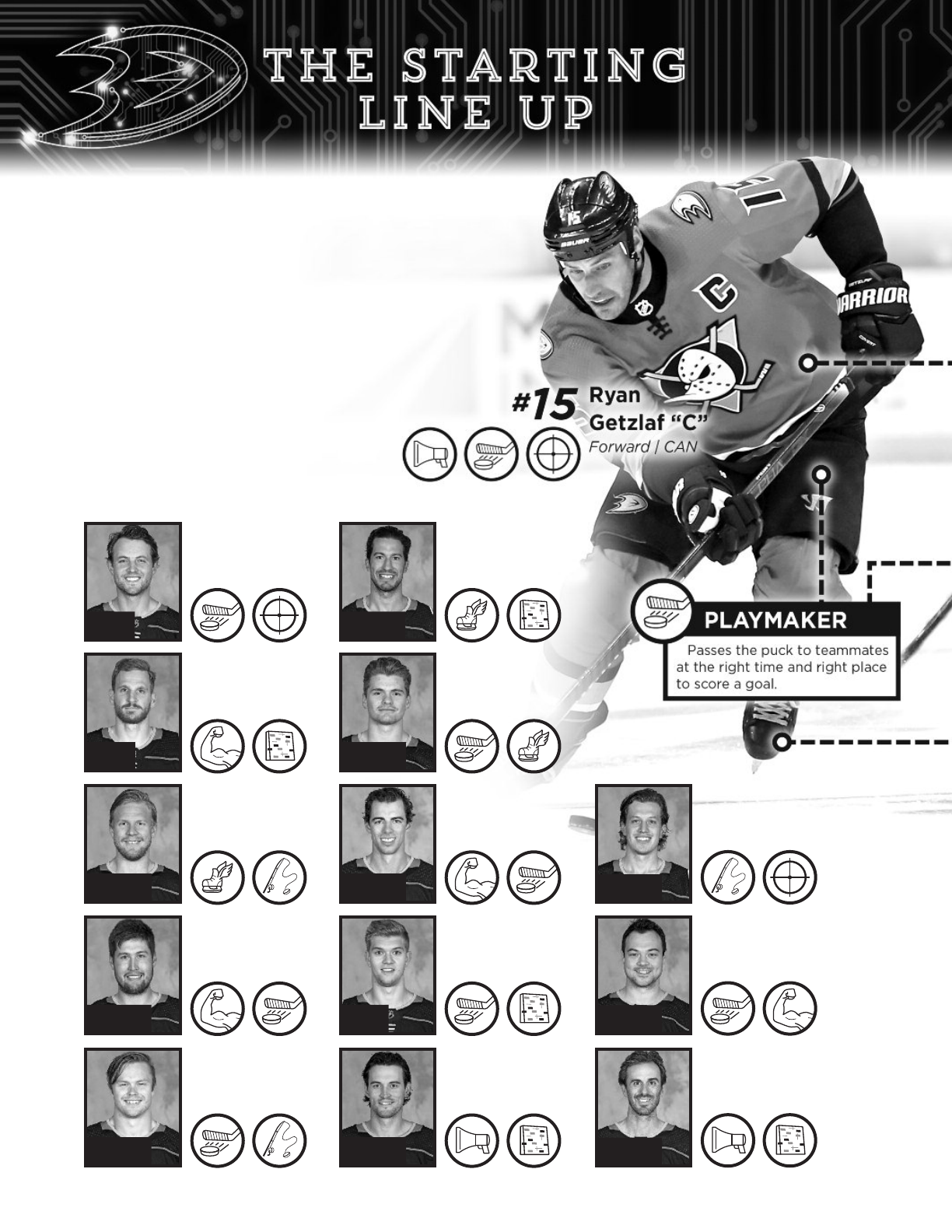
A hockey puck can’t reach its potential without the passing,
shooting, and stickhandling from Anaheim Ducks players.
That’s because players have their own abilities to turn the
puck into an amazing play leading to a Ducks goal. When
Coach Eakins looks at his roster of players each night, he has
a very difficult decision to make with his starting line-up.
He has to choose three forwards, two defensemen,
and one goaltender to take the face-off at the start of
each game. This decision is an important one because
teams that start games well usually wins them.
Are you ready to select your best starting
line-up for the next Ducks game? Take a
look at what these Anaheim Ducks
components can do with the puck!
Cam
Fowler
Defenseman | USA
Korbinian
Holzer
Defenseman | DEU
Ondrej
Kase
Forward | CZE
Nick
Ritchie
Forward | CAN
Max
Jones
Forward | CAN
*Roster as of 1/20/20
Michael
Del Zotto
Defenseman | CAN
Sam
Steel
Forward | CAN
Derek
Grant
Forward | CAN
Brendan
Guhle
Defenseman | CAN
John
Gibson
Goalie | USA
Rickard
Rakell
Forward | SWE
Devin
Shore
Forward | CAN
Ryan
Miller
Goalie | USA
#
4
#
5
#
25
#
37
#
49
#
44
#
34
#
38
#
2
#
36
#
67
#
29
#
30
14
Josh
Manson
Defenseman | CAN
Jacob
Larsson
Defenseman | SWE
Josh
Mahura
Defenseman | CAN
Troy
Terry
Forward | USA
Carter
Rowney
Forward | CAN
Nicolas
Deslauriers
Forward | CAN
Max
Comtois
Forward | CAN
Adam
Henrique
Forward | CAN
#
42
#
32
#
76
#
61
#
24
#
20
#
53
#
14
15
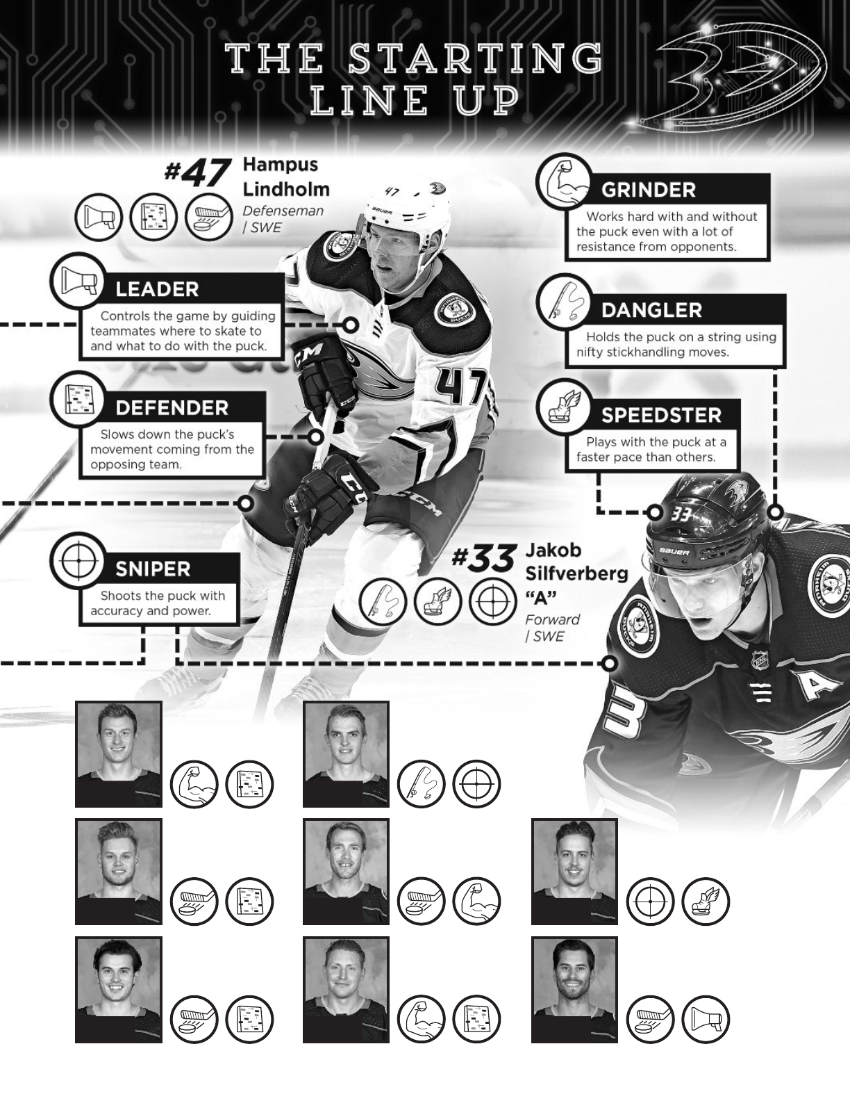
When it comes to circuits, electrons can’t reach their full potential without some important players called
electronic components. Similar to Ducks players, components come in many different forms, types, and
sizes. They also have their own ability to turn electron flow into something useful. Some components can
light up a dark room, others are microscopic, and then there are ones that can slow down electron flow
with an opposing force called resistance. The best part about components is that you can use many of
them in a circuit. You just need to connect them the right way. Once you do, you’ll be able to Light the
Lamp or accomplish any task with electricity. Let’s learn more about the components for your circuit and
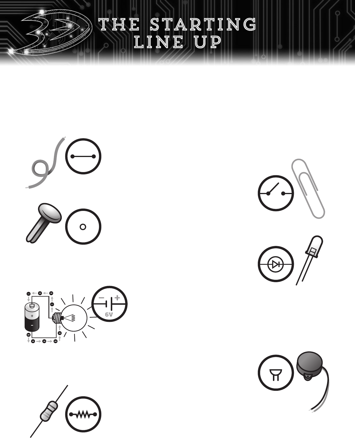
the important role they play to Light the Lamp. This is your starting line-up!
Wires – Orange Wire
A wire uses a long piece of conductive material that allows
electrons to flow between two points. The orange jacket
around the wire is an insulator used to keep electricity from
flowing through your hand.
Switch – Paper Clip
There are many types of switches, but this door like switch
uses a metal paper clip to open and close a gap in the circuit.
Sound Source – Buzzer
This buzzer turns electron flow into sound. It uses a magnet and a coil
of wire to vibrate a thin sheet of paper. The buzzer will only work
if the red wire (+) and black wire (-) are hooked up
correctly to the terminals.
Resistors – 220Ω, 5,000Ω, and 10,000Ω
Components can break, or “blow”, when the voltage or push from
electron flow is too great. When this happens, it’s important to add a
defensive component called a resistor to the circuit. A resistor’s defensive rating,
or resistance, is measured in ohms (Ω). Therefore, a 10,000Ω resistor has the
ability to slow down electron flow better than a 220Ω resistor.
Light Source – Low Voltage LED
These low-voltage light emitting diodes (LED) turn electron flow
into a red light. The long wire is the positive (+) pole and the
shorter one is the negative (-) pole. A LED must be connected in
the right direction or else it may break.
Terminal – Brass Fasteners
The brass fastener connects many wires and components at an
intersection called a terminal. Most circuit boards use a material
called solder in order to accomplish this same task.
+
-
+
-
+
-
16
Power Source – Four (4) AAA Batteries
Electrons are present in everything but in order for them to start
flowing they’ll need a power source. A power source like a battery uses
chemicals to generate the potential energy, or voltage (v), needed to
give electrons in a circuit a good push. Once they start flowing, they’ll
head towards the positive (+) pole, or side, of the battery and back out of the
negative (-) pole so that it can go around the circuit again and again. The amount
of voltage you need for a circuit depends on what you want to do.
Step 1: Assemble your simple circuit without a resistor.
• Find a clear plastic or glass cup.
• Install a battery holder with 4 AAA batteries at terminals 01(-) and 02(+).
• Install a switch at [02-03] and keep it in the OPEN position.
• Insert a LED at 06(+) and 07(-).
• Insert wires at all other segments [03-04], [04-05], [05-06], [07-08], [08-09], and [01-09]
to complete the circuit.
• Place the cup over the LED. This is for safety!
Step 2: Turn on your circuit.
• Swing the paper clip to the CLOSE position so that it touches the brass fastener at 03.
Keep your circuit on for at least 30 seconds.
• Record your findings in the chart below. Measure the brightness of the LED
(0-no light; 10-very bright). Then, write down what you saw in the notes column.
Step 3: Let’s ADD a defensive force!
• Turn o your circuit to the OPEN position (remove the cup over the LED if it’s still there).
• Replace the wire at [03-04] with a 220Ω resistor.
• Turn on your circuit and record your findings in the chart below.
Step 4: Let’s INCREASE the defensive force!
• Repeat step 3 with a 5,000Ω resistor (green, brown, black, brown, brown) and then a
10,000Ω resistor (brown, black, black, red, brown).
QUESTIONS
1. Why do you think the LED stopped working when there were no resistors
connected to the circuit? Explain.
_____________________________________________________________
_____________________________________________________________
_____________________________________________________________
2. According to your findings, how did replacing the resistors affect the LED?
What do you think would happen to the LED (and circuit) if you continued
to add more resistance? Explain.
_____________________________________________________________
_____________________________________________________________
_____________________________________________________________
Resistor LED Brightness Notes
None 0 1 2 3 4 5 6 7 8 9 10
220Ω 0 1 2 3 4 5 6 7 8 9 10
5,000Ω 0 1 2 3 4 5 6 7 8 9 10
10,000Ω 0 1 2 3 4 5 6 7 8 9 10
17
RESIST
It’s time to watch some great defense against electron flow. Follow the
directions below to see the role that resistors play in a circuit.
Don’t forget to
remove the
batteries when
you’re done!
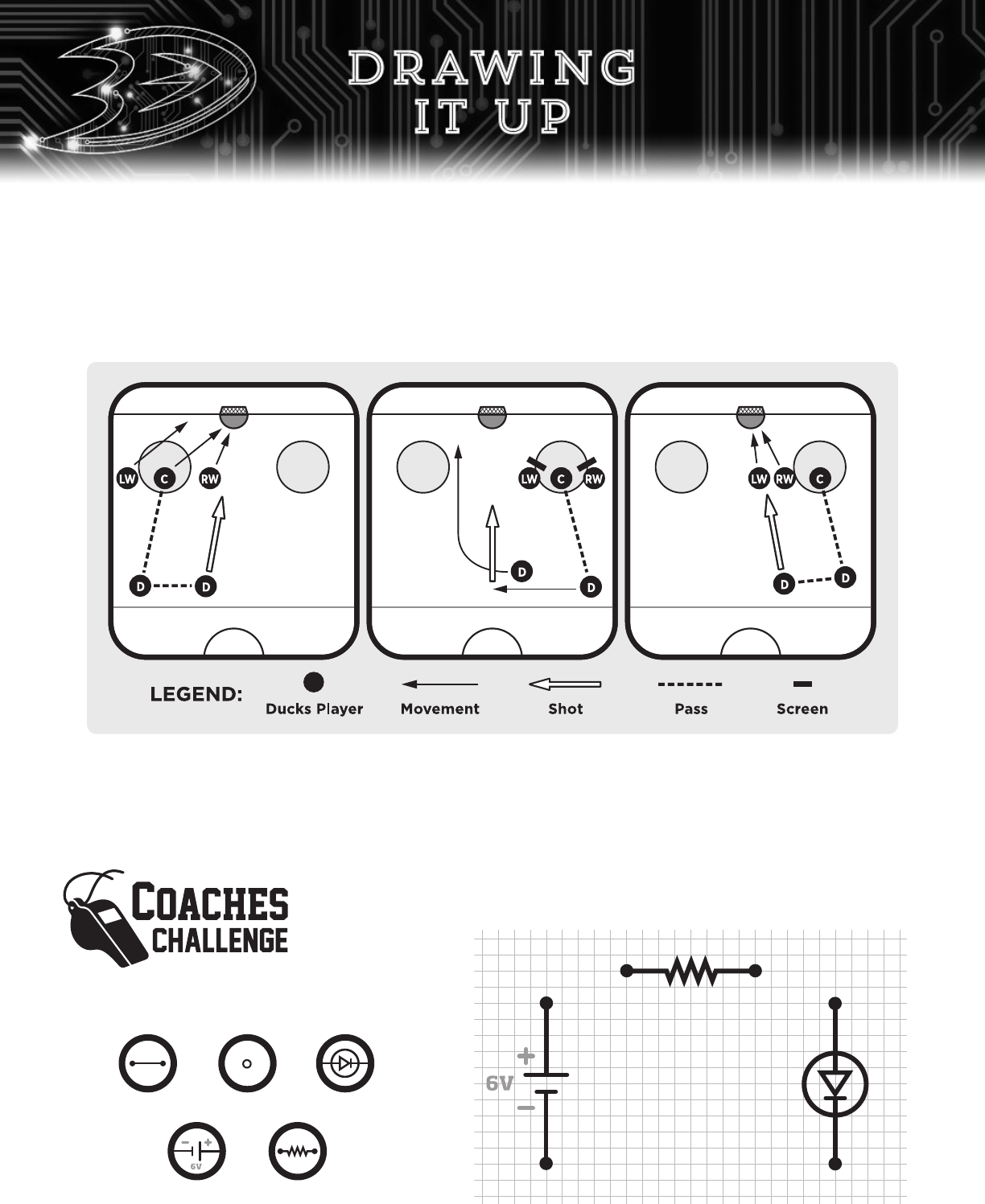
Drawing a circuit diagram is similar to drawing up a play in hockey. It uses a variety of shapes, symbols,
and lines to represent a circuit that you want to build. These diagrams help engineers know which
components to use, where to place them, and how to connect them to form the circuit. To learn how to
draw one of these helpful pictures, take a look at the following steps that were taken to create a diagram
for the circuit on page 10.
Step 1: Identify
the components
you want to build a
circuit with. You’ll
need to know their
symbol so that you can draw them. They can
be found on page 16 of this workbook.
Step 2: Place your components by drawing
them into position.
In hockey, a team is given only one timeout. It’s a 30-second stop in the game coaches use to speak to
players or give them a quick rest. That’s why this important timeout is often saved for the final minutes
when a game tying goal or a key defensive stop is needed. During a timeout, players huddle around their
coach as he draws shapes, symbols, and lines on a white board. This is called drawing up a play. They
are instructions showing players where to stand, who to pass to, and where to skate to once the puck is
dropped. Check out some of the hockey plays Coach Eakins has drawn up in the past that have led to
some exciting Light the Lamp moments.
Wire Terminal LED
Battery Resistor
18
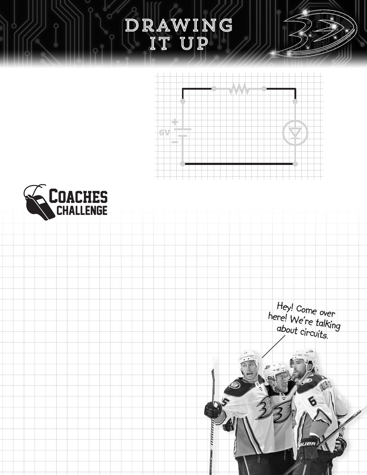
Step 3: Connect the components with
lines to complete the circuit.
You can draw them in any
way you wish to. However,
engineers draw straight lines
for a cleaner look so that others
seeing this picture can know
exactly how to build the circuit.
In the space below, use the three steps to draw a circuit diagram for the
circuit on page 12.
19
Another reason engineers draw circuit diagrams is because circuits can
get quite complicated once you start adding more “players”. This tool
comes in handy whether you want to add a few components or even
thousands of them. And it’s even more important to use when they’re
connected in series or parallel.
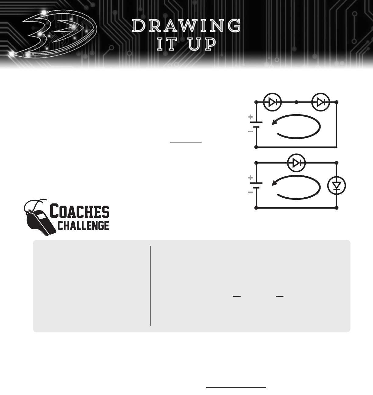
SERIES CIRCUIT
A series circuit connects every component in a single path. Electrons
flow through one component, then the next, and continues to do this
until it makes its way around to the battery. This type of connection is
very simple to build but it has some drawbacks. For instance, connecting
two LED bulbs in series will be half as bright than a circuit with only one
LED bulb. The voltage drops off, or decreases, each time electrons flow
through a component. Also, if a component breaks, the entire series
circuit will turn off.
Build the following circuits to see how
components, like red LED bulbs, work when
they are connected in series. Use terminals
01 to 09 for this activity.
One LED Bulb Simple Circuit
Step 1: Assemble the circuit from
page 12 with the switch in
the OPEN position.
Step 2: Turn on the circuit.
Step 3: Measure the brightness
of the bulb and record it
in the chart (0-no light;
10-very bright).
Two LED Bulb Series Circuit
Step 1: Turn o the circuit to the OPEN position.
Step 2: Remove the components from A [05-06], B [06-07],
and C [07-08].
Step 3: Attach the following components:
• Wire segment at B [06-07].
• LED bulbs at A [05-06] and C [07-08]. Make sure the
longer leads (+) for each LED are connected to 05 and 07.
Step 4: Turn on the circuit.
Step 5: Measure the brightness of the bulbs at A and C and
record them in the chart.
Questions:
1. Compare the LED bulbs between the simple and series circuits. What caused them to light up differently?
______________________________________________________________________________________
______________________________________________________________________________________
2. How would the LED bulbs in the series circuit change if a third LED was added? Explain.
(HINT: Replace the wire at B [06
-07] with an LED.)
______________________________________________________________________________________
______________________________________________________________________________________
3. What would happen to the series circuit if one of the LED bulbs was removed?
(HINT: Remove a LED bulb while the circuit is on.)
______________________________________________________________________________________
______________________________________________________________________________________
Series Circuit Examples
20
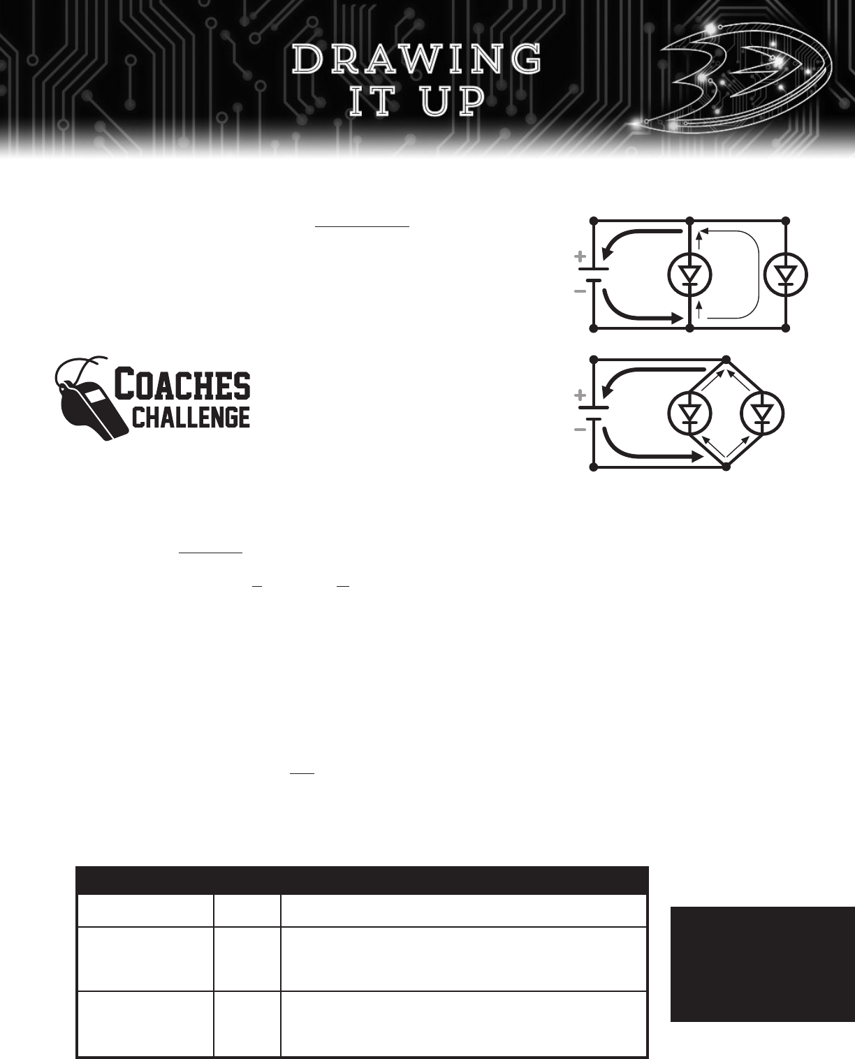
PARALLEL CIRCUIT
In a parallel circuit, electrons follow multiple paths. When a circuit
splits, some electrons will follow one path while the rest will flow into
the other ones. Although this happens, electrons will always meet back
up and return to the battery together. Parallel circuits take more time
to set up but they have an important feature that’s advantageous to
use. They can continue to work even if a component in one path
breaks. That’s why long strands of holiday lights are formed this way.
It can continue to decorate your home even when a bulb goes out.
Two LED Bulb Parallel Circuit
Step 1: Turn o the circuit to the OPEN position.
Step 2: Remove the components from A [05-06], B [06-07], and C [07-08].
Step 3: Attach the following components:
• Wire segments at [05-10], [10-11], [10-13], [12-15], [14-15], and [08-15].
• 220Ω resistor at [03-04].
• LED bulbs at D [11-12] and E [13-14]. Make sure their longer leads (+) are connected to 11 and 13.
Step 4: Turn on the circuit.
Step 5: Measure the brightness of the bulbs at D and E and record them in the chart.
Questions:
1. Compare the brightness of the LED bulbs formed in simple, series, and parallel circuits. What did you see?
______________________________________________________________________________________
______________________________________________________________________________________
2. What would happen to the circuit if one of the LED bulbs was removed? Explain.
(HINT: Go ahead and pull out one LED bulb!)
______________________________________________________________________________________
______________________________________________________________________________________
Build the following circuit to see how
components, like red LED bulbs, work when
they are connected in parallel. Follow the
directions carefully because this circuit is
unlike anything you’ve seen before!
# of LED Brightness
1 LED @ B: 0 1 2 3 4 5 6 7 8 9 10
2
LED @ A: 0 1 2 3 4 5 6 7 8 9 10
LED @ C: 0 1 2 3 4 5 6 7 8 9 10
2
LED @ D: 0 1 2 3 4 5 6 7 8 9 10
LED @ E: 0 1 2 3 4 5 6 7 8 9 10
Formation
Simple Circuit
Series Circuit
Parallel Circuit
CHART
Parallel Circuit Examples
21
Don’t forget to
remove the
batteries when
you’re done!
Congratulations. You did it! But even as a new engineer who has just harnessed the powers of electricity,
your journey is not over. In fact, it gets better. The best part of being an engineer isn’t learning about math
formulas or electricity concepts. Instead, it’s about using all of this information to think BIG! Every day,
engineers answer the call to improve on past inventions, build the next cool gadget, or make things that
help others in need. Are you ready to take on this challenge when it comes to hockey? Here are some easy
steps called The Engineering Design Process that will help you Light the Lamp creatively. We can’t wait
to see you innovate!
Use your journal to take notes or write down ideas that will help improve your Light the Lamp circuit.
Share your Light the Lamp Challenge photos and videos on social media with
#duckslightthelamp or upload them to bit.ly/2020FFFTprojects. We’ll show
them throughout the event on March 9!
22
STEP 1:
ASK A
QUESTION
Thinking big always starts with a big question
that deals with the problem to solve or an object
to improve upon. What can you do to make the
Light the Lamp circuit bigger and better?
STEP 2:
BRAINSTORM
Work alone or with a large group to create a list of ideas and write
them all down in a journal or on a whiteboard. Remember, all ideas
are good ideas! What ideas do you have in your head?
STEP 3:
DESIGN
Take your best ideas and decide on the best solution.
Then, draw pictures and circuit diagrams to create
the plans for how it will be built. What are you going
to design and how will it be made?
STEP 4:
BUILD, TEST,
& REDESIGN
Assemble your circuit and watch it come to life. If it doesn’t
work, don’t worry. Even the best electrical engineers have to
go back to the drawing board. How will you build, test,
and improve your design?
STEP 5:
SHARE!
Don’t keep your design a secret! Imagine a world where no
one shared their ideas. There wouldn’t be life-saving medical
equipment or spacecraft to explore the Universe. Share
your work in a report, through a presentation, or using
technology like videos or apps. How will you share your
work with others?
23
ARE YOU READY FOR THE
“LIGHT THE LAMP”
CHALLENGE?
Presented by
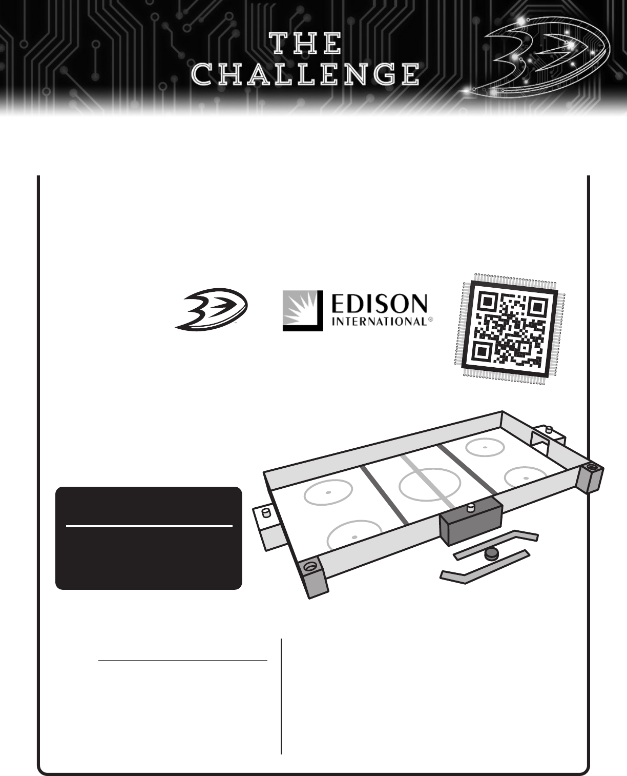
Pass, shoot, score, and celebrate with a
real table top hockey rink designed by you!
Work together with your classmates and submit your best Light the Lamp
Challenge projects, including this one from Instructables.com, before coming
to the First Flight Field Trip. We’ll be choosing the coolest hockey
rinks created by students like you and reward them
with some sweet prizes. So, what are you
waiting for? Get started so that you
can Light the Lamp today!
1. Go to bit.ly/2020FFFTprojects and click
on the “Light the Lamp Challenge” banner
.
2. Click through the tutorial on
instructables.com. You’ll need help
from your teacher on this one.
3. Follow the directions to learn how
you can create a super cool project to
Light the Lamp.
Here’s how to enter the “Light the Lamp Challenge”
4. Get approval from your teacher. Your teacher won’t
know to give you the green light to start until you tell
them the secret phrase - “I’m ready to Light the Lamp!”
5. Follow the directions at instructables.com to build
your table top rink with your classmates. You’ll be
lighting the lamp in no time!
6. Share your photos or videos with #duckslightthelamp
or upload them at bit.ly/2020FFFTprojects.
3D
Printer
Autographed
Items
And More!
C
h
e
c
k
o
u
t
t
h
e
s
e
C
O
O
L
p
r
i
z
e
s
y
o
u
r
c
l
a
s
s
r
o
o
m
c
o
u
l
d
w
i
n
!
CH
AL
L
ENG
E

24