Owner's Manual
Original Instructions
renoitidnoC riA tilpS
AIR CONDITIONER
Thank you for choosing commercial air conditioners. Please read
this Owner’ s Manual carefully before operation and retain it for
future reference.

Content
Operation Notices
Precautions............................................................................................................ 1
Parts name ............................................................................................................ 9
Screen Operation Guide
Buttons on remote controller ............................................................................... 11
Introduction for icons on display screen .............................................................. 11
Introduction for buttons on remote controller .......................................................12
Function introduction for combination buttons ..................................................... 16
Operation guide ................................................................................................... 18
Replacement of batteries in remote controller ..................................................... 18
Emergency operation .......................................................................................... 19
Maintenance
Clean and maintenance....................................................................................... 20
Malfunction
Malfunction analysis ............................................................................................ 22
Installation Notice
Installation dimension diagram ............................................................................ 26
Tools for installation .............................................................................................28
Selection of installation location .......................................................................... 28
Requirements for electric connection .................................................................. 29
Installation
Installation of indoor unit......................................................................................30
Check after installation ........................................................................................ 35
Test and operation
Test operation ...................................................................................................... 35
Attachment
......................................................................... 36
..................................................................................
.
38
This appliance is not intended for use by persons (including children) with reduced physical,
sensory
or mental capabilities or lack of experience and knowledge, unless they have been given supervision
or instruction concerning use of the appliance by a person responsible for their safety.
Children should be supervised to ensure that they do not play with the appliance.
Pipe expanding method
Safety precautions for installing and relocating the unit
...................................... 27
If it needs to install, move or maintain the air conditioner, please contact dealer or local service center
to conduct it at first. Air conditioner must be installed, moved or maintained by appointed unit. Otherw-
ise, it may cause serious damage or personal injury or death.
Explanation of Symbols
Indicates a hazardous situation that, if not avoided, will
result in death or serious injury.
Indicates a hazardous situation that, if not avoided, could
result in death or serious injury.
Indicates a hazardous situation that, if not avoided, may
result in minor or moderate injury.
Indicates important but not hazard-related information,
used to indicate risk of property damage.
Indicates a hazard that would be assigned a signal word
WARNING or CAUTION.
WARNING
CAUTION
DANGER
N OT IC E
Precautions
WARNING
Do not connect air conditioner to multi-purpose socket.
This appliance can be used by children aged from 8
Operation and Maintenance
If the supply cord is damaged, it must be replaced by
the manufacturer, its service agent or similarly qualified
persons in order to avoid a hazard.
Do not spray water on indoor unit. It may cause electric
shock or malfunction.
Otherwise, it may cause fire hazard.
Children shall not play with the appliance.
Cleaning and user maintenance shall not be made by
children without supervision.
years and above and persons with reduced physical,
sensory or mental capabilities or lack of experience
and knowledge if they have been given supervision or
instruction concerning use of the appliance in a safe
way and understand the hazards involved.
Do not wash the air conditioner with water to avoid
electric shock.
After removing the filter, do not touch fins to avoid injury.
Do not use fire or hair dryer to dry the filter to avoid
deformation or fire hazard.
Do disconnect power supply when cleaning air
conditioner. Otherwise, it may cause electric shock.
.
1
Do not block air outlet or air inlet. It may cause
malfunction.
remote controller may be broken.
● Power cord is overheating or damaged.
● There’s abnormal sound during operation.
● Circuit break trips off frequently.
● Air conditioner gives off burning smell.
● Indoor unit is leaking.
contact the dealer or qualified professionals for service.
When turning on or turning off the unit by emergency
operation switch, please press this switch with an insulating
object other than metal.
outlet. It may cause personal injury or damage.
Precautions
WARNING
conditioner and disconnect power immediately, and then
If the air conditioner operates under abnormal conditions,
it may cause malfunction, electric shock or fire hazard.
Do not spill water on the remote controller, otherwise the
electric shock or damage. Please contact dealer when
you need to repair air conditioner.
Do not repair air conditioner by yourself. It may cause
objects. It may cause damage or personal injury.
Do not step on top panel of outdoor unit, or put heavy
When below phenomenon occurs, please turn off air
Do not extend fingers or objects into air inlet or air
Maintenance must be performed by qualified
professionals. Otherwise, it may cause personal injury
or damage.
2
Do install the circuit break. If not, it may cause malfunction.
of at least 3mm in all poles should be connected in fixed
wiring.
magnet buckle
and heating buckle function, it can protect
the circuit-short and
overload.
power supply circuit and circuit break.
Precautions
WARNING
note
the following table.Air switch should be included
Make sure the power supply matches with the
requirement of air conditioner.Unstable power supply or
incorrect wiring or malfunction. Please install proper power
supply cables before using the air conditioner.
An all-pole disconnection switch having a contact separation
Must follow the electric safety regulations when installing
the unit.
grounding wire of power socket.
Properly connect the live wire, neutral wire and
any work related to electricity and safety.
Be sure to cut off the power supply before proceeding
Including an circuit break with suitable capacity, please
Air Conditioner should be properly grounded. Incorrect
Don't use unqualified power cord.
grounding may cause electric shock.
According to the local safety regulations, use qualified
Installation must be performed by qualified professionals.
Otherwise, it may cause personal injury or damage.
Attachment
3
Installation must be performed in accordance with the
persons in order to avoid a hazard.
must be properly grounding with specialized grounding
device by a professional. Please make sure it is always
grounded effectively, otherwise it may cause electric shock.
The appliance must be positioned so that the plug is
accessible.
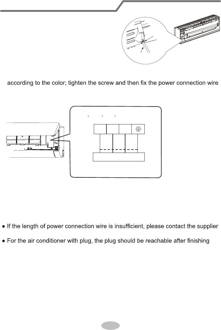
If the length of power connection wire is insufficient, please
contact the supplier for a new one. Avoid extending the
wire by yourself.
All wires of indoor unit and outdoor unit should be
connected by a professional.
national wiring regulations.
requirement of NEC and CEC by authorized personnel
only.
Precautions
WARNING
wire, which can't be used for other purposes.
The grounding resistance should comply with national
electric safety regulations.
The air conditioner is the first class electric appliance. It
keep the interconnection cable away from the copper
tube.
The temperature of refrigerant circuit will be high, please
the manufacturer, its service agent or similarly qualified
If the supply cord is damaged, it must be replaced by
The yellow-green wire in air conditioner is grounding
The appliance shall be installed in accordance with
Do not put through the power before finishing installation.
4
The indoor unit should be installed close to the wall.
reachable after finishing installation.
far away from animals or plants.If it is unavoidable,
please add the fence for safety purpose.
Precautions
WARNING
FCC WARNING
place, only the qualified person can perform the work.
Otherwise, it may cause personal injury or damage.
If you need to relocate the air conditioner to another
must be installed in the line.
For the air conditioner without plug, an circuit break
Select a location which is out of reach for children and
For the air conditioner with plug, the plug should be
5
Instructions for installation and use of this product are
provided by the manufacturer.
expressly approved by the party responsible for
compliance could void the user’s authority to operate
the equipment.
WARNING: Changes or modifications to this unit not
FCC STATEMENT
Operation is subject to the following two conditions :
This device complies with Part 15 of the FCC Rules.

pursuant to part 15 of the FCC Rules. These limits are
designed to provide reasonable protection against
equipment generates, uses and can radiate radio
● Reorient or relocate the receiving antenna.
● Increase the separation between the equipment and
receiver.
● Connect the equipment into an outlet on a circuit
● Consult the dealer or an experienced radio/TV
different from that to which the receiver is connected.
technician for help.
interference to radio communications.
comply with the limits for a Class B digital device,
Precautions
FCC STATEMENT
accordance with the instructions,may cause harmful
harmful interference in a residential installation. This
undesired operation.
frequency energy and, if not installed and used in
However, there is no guarantee that interference will
does cause harmful interference to radio or television
correct the interference by one or more of the following
measures:
equipment off and on, the user is encouraged to try to
not occur in a particular installation. If this equipment
reception, which can be determined by turning the
NOTE: This equipment has been tested and found to
(1) this device may not cause harmful interference,
and (2) this device must accept any interference
received,including interference that may cause
6
Precautions
Le présent appareil est conforme aux CNR d'Industrie
licence. L'exploitation est autorisée aux deux conditions
tout brouillage radioélectrique subi, même si le
undesired operation of the device.
IC STATEMENT
brouillage, et (2) l'utilisateur de l'appareil doit accepter
Canada applicables aux appareils radio exempts de
interference, and (2) this device must accept any
suivantes : (1) l'appareil ne doit pas produire de
brouillage est susceptible d'en compromettre le
fonctionnement.
interference, including interference that may cause
This device complies with Industry Canada licence-
This equipment complies with FCC’s and IC’s RF
radiation exposure limits set forth for an uncontrolled
environment. The antenna(s) used for this transmitter
must be installed and operated to provide a separation
distance of at least 20 cm from all persons and must
exempt RSS standard(s). Operation is subject to the
following two conditions: (1) this device may not cause
not be collocated or operating in conjunction with any
other antenna or transmitter. Installers must ensure that
20cm separation distance will be maintained between
the device (excluding its handset) and users.
Cet appareil est conforme aux limites d’exposition au
rayonnement RF stipulées par la FCC et l’IC pour une
utilisation dans un environnement non contrôlé. Les
7
Precautions
IC STATEMENT
près d’autres antennes ou émetteurs ou fonctionner
antennes utilisées pour cet émetteur doivent être
installées et doivent fonctionner à au moins 20
cm de
distance des utilisateurs et ne doivent pas être placées
distance de 20 cm sépare l’appareil (à l’exception du
combiné) des utilisateurs.
avec ceux-ci. Les installateurs doivent s’assurer qu’une
8
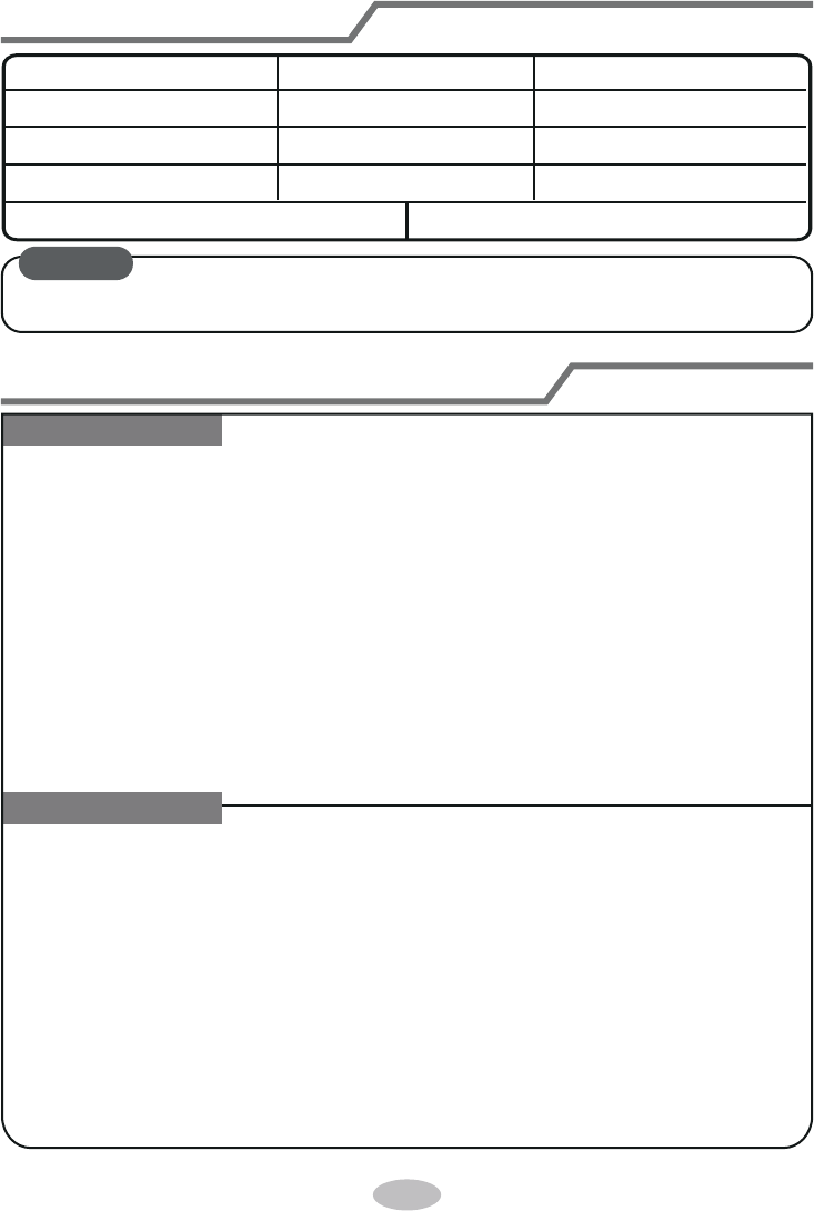
Working temperature range
Indoor side DB/WB(°C/°F) Outdoor side DB/WB(°C/°F)
Maximum cooling 26.7/19.4(80/66.9) 46.1/23.9(115/75)
Maximum heating 26.7/-(80/-) 23.9/18.3(75/64.9)
● The operating temperature range (outdoor temperature) for cooling only unit is
-18
(-0.4°F)~46.1 (115°F); for heat pump unit is-20 (-4°F)~46.1 (115°F).
NOTICE:
9
(Display content or position may be different from above
graphics, please refer to actual products)
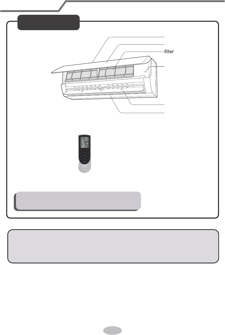
Parts Name
Indoor Unit
air inlet
panel
aux.button
horizontal louver
air outlet
Actual product may be different from above graphics, please refer to actual
products.
NOTICE:
remote control
temp.
indicator
display
For some model:
receiver
window
Power indicatior
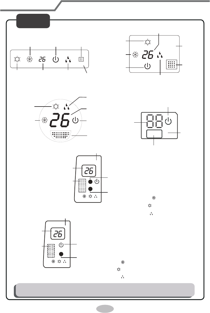
Parts name
Display content or position may be different from above graphics, please refer to actual
products.
Display
W R G
temp.
indicator
display
receiver
window
W R O
temp.
indicator
display
receiver
window
heating
indicator
temp.
indicator
cooling
indicator
power
indicator
receiver
window
drying
indicator
display
For some model:
For some model:
For some model:
For some model:
heating
indicator
temp.
indicator
cooling
indicator
power
indicator
receiver
window
drying
indicator
display
For some model:
heating
indicator
temp.
indicator
cooling
indicator
power
indicator
receiver
window
drying
indicator
G
W
R
Power LED color indicator:
Green-status-ON.
Red -status-OFF.
Mode LED color indicator:
White-W-Cool Mode-
Red-R-Heat Mode-
Green-G-Dry Mode-
O
W
R
Power LED color indicator:
Green-status-ON.
Red -status-OFF.
Mode LED color indicator:
White-W-Cool Mode-
Red-R-Heat Mode-
Orange-O-Dry Mode-
(only for heating model)
(only for heating model)
10
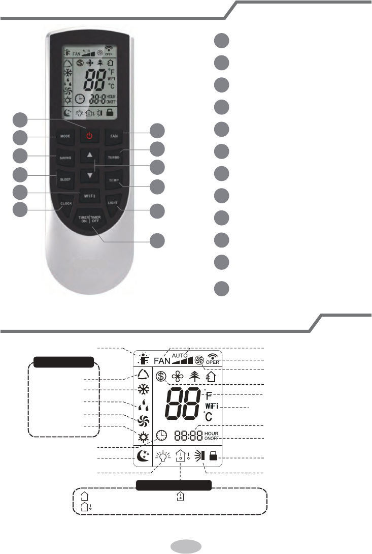
Buttons on remote controller
Introduction for icons on display screen
1
5
3
6
8
10
12
11
9
7
4
2
1
2
3
4
5
6
7
8
9
10
11
12
ON/OFF button
MODE button
FAN button
SWING button
TURBO button
TEMP button
WiFi button
LIGHT button
CLOCK button
TIMER ON / TIMER OFF
button
SLEEP button
▲/ button
▲
Send signal
Turbo mode
8
℃
heating function
Set temperature
Set time
TIMER ON /
TIMER OFF
Child lock
Up & down swing
Set fan speed
Light
Temp. display type
:Set temp.
:Outdoor ambient temp.
:Indoor ambient temp.
Sleep mode
Clock
Heat mode
Fan mode
Dry mode
Cool mode
Auto mode
Operation mode
I feel
WiFi
This is a general remote controller.Some
models have this function while some
do not. Please refer to the actual models.
{
12
● When selecting auto mode, air conditioner will operate automatically according
to ex-factory setting. Set temperature can’t be adjusted and will not be displayed
as well. Press "FAN" button can adjust fan speed. Press "SWING" button can
adjust fan blowing angle.
● After selecting cool mode, air conditioner will operate under cool mode. Cool
indicator on indoor unit is ON(This indicator is not available for some models).
Press "▲" or " " button to adjust set temperature. Press "FAN" button to adjust
fan speed. Press "SWING" button to adjust fan blowing angle.
● When selecting dry mode, the air conditioner operates at low speed under dry
mode. Dry indicator on indoor unit is ON(This indicator is not available for some
models). Under dry mode, fan speed can’t be adjusted. Press "SWING" button
to adjust fan blowing angle.
● When selecting fan mode, the air conditioner will only blow fan, no cooling and
no heating. Press "FAN" button to adjust fan speed. Press "SWING" button to
adjust fan blowing angle.
● When selecting heating mode, the air conditioner operates under heat mode.
Heat indicator on indoor unit is ON(This indicator is not available for some models).
Introduction for buttons on remote controller
Note:
● After putting through the power, the air conditioner will give out a sound.
Operation indictor is ON (red indicator, the colour is different for different models).
After that, you can operate the air conditioner by using remote controller.
●
Under on status, pressing the button on the remote controller, the signal icon " "
on the display of remote controller will blink once and the air conditioner will give
out a “de” sound, which means the signal has been sent to the air conditioner.
● Under off status, set temperature and clock icon will be displayed on the display
of remote controller (If timer on, timer off and light functions are set, the corre-
sponding icons will be displayed on the display of remote controller at the same
time); Under on status, the display will show the corresponding set function icons.
ON/OFF button
MODE button
▲
1
2
Press this button to turn on the unit. Press this button again to turn off the unit.
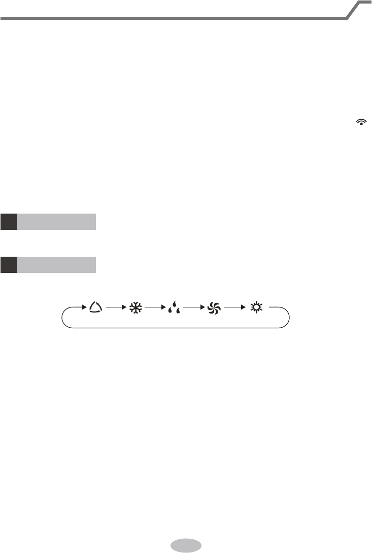
Press this button to select your required operation mode.
AUTO COOL FANDRY HEAT
● This is a general use remote controller, it could be used for the air conditioners
with multifunction; For some function, which the model doesn't have, if press
the corresponding button on the remote controller that the unit will keep the
original running status.
13
Introduction for buttons on remote controller
FAN button
SWING button
3
4
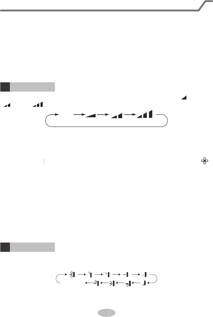
Press this button can select up&down swing angle. Fan blow angle can be selected
circularly as below:
Press "▲" or " " button to adjust set temperature. Press "FAN" button to adjust
fan speed. Press "SWING" button to adjust fan blowing angle. (Cooling only unit
won’t receive heating mode signal. If setting heat mode with remote controller,
press ON/OFF button can’t start up the unit).
Note:
● For preventing cold air, after starting up heating mode, indoor unit will delay 1~5
minutes to blow air (actual delay time is depend on indoor ambient temperature).
● Set temperature range from remote controller: 16~30
℃
(61~86°F); Fan speed:
auto, low speed, medium speed, high speed.
This function indicates that moisture on evaporator of indoor unit will be blowed
after the unit is stopped to avoid mould.
Having set X-FAN function on: After turning off the unit by pressing ON/OFF
button indoor fan will continue running for a few minutes. at low speed. In this
period, Hold fan speed button for 2s to stop indoor fan directly.
Having set X-FAN function off: After turning off the unit by pressing ON/OFF
button, the complete unit will be off directly.
X-FAN function
Hold fan speed button for 2s in COOL or DRY mode, the icon “ ” is
displayed and the indoor fan will continue operation for a few minutes in order to dry
the indoor unit even though you have turned off the unit. After energization, X-FAN
OFF is defaulted. X-FAN is not available in AUTO, FAN or HEAT mode.
●
●
●
Note:
● Under AUTO speed, air conditioner will select proper fan speed automatically
according to ex-factory setting.
● Fan speed under dry mode is low speed.
Pressing this button can set fan speed circularly as: auto (AUTO), low( ) ,medium
( ), high( ).
Auto
no display
(horizontal louvers stops
at current position)
▲
14
SLEEP button
TEMP button
7
8
Introduction for buttons on remote controller
▲
▲
Under COOL or HEAT mode, press this button to start up sleep function.
" " icon is displayed on remote controller. Press this button again to cancel sleep
function and " " icon will disappear.
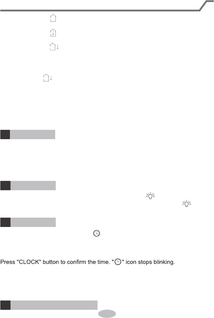
By pressing this button, you can see indoor set temperature, indoor ambient temp-
erature or outdoor ambient temperature on indoor unit’s display. The setting on
remote controlleris selected circularly as below:
no display
TURBO button
5
Under COOL or HEAT mode, press this button to turn to quick COOL or quick
HEAT mode. " " icon is displayed on remote controller. Press this button again
to exit turbo function and " " icon will disappear.
▲
▲/ button
6
● Press "▲" or " " button once increase or decrease set temperature 1
℃(1°F)
.
Holding "▲" or " " button, 2s later, set temperature on remote controller will
change quickly. On releasing button after setting is finished, temperature indica-
tor on indoor unit will change accordingly. (Temperature can’t be adjusted under
auto mode)
● When setting TIMER ON, TIMER OFF or CLOCK, press "▲" or " " button to
adjust time. (Refer to CLOCK, TIMER ON, TIMER OFF buttons) When setting
TIMER ON, TIMER OFF or CLOCK, press "▲" or " " button to adjust time. (Refer
to CLOCK, TIMER ON, TIMER OFF buttons)
▲
▲
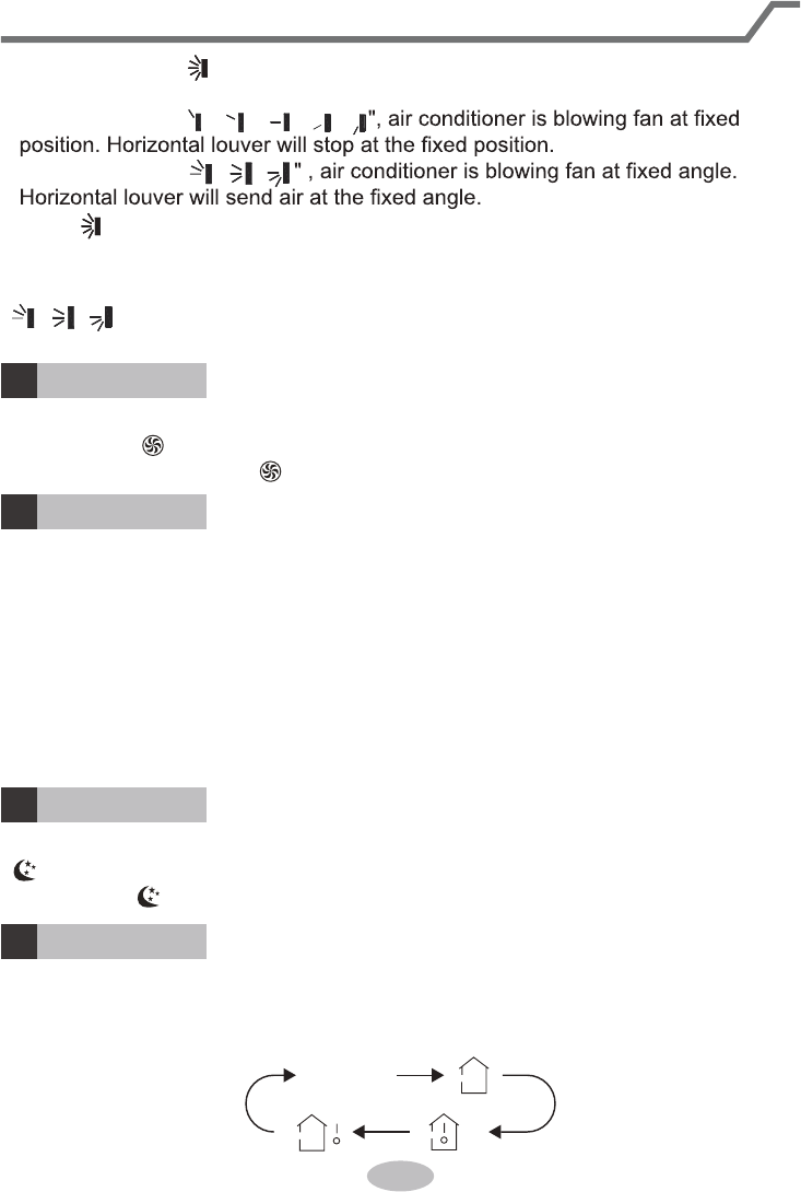
● When selecting " ", air conditioner is blowing fan automatically. Horizontal
louver will automatically swing up & down at maximum angle.
● When selecting "
、
、
、
、
● When selecting "
、
、
● Hold " " button above 2s to set your required swing angle. When reaching your
required angle, release the button.
Note:
"
、
、
" may not be available. When air conditioner receives this signal, the
air conditioner will blow fan automatically.
15
● It’s defaulted to display set temperature when turning on the unit. There is no
display in the remote controller.
● Only for the models whose indoor unit has dual-8 display.
● When selecting displaying of indoor or outdoor ambient temperature, indoor
temperature indicator displays corresponding temperature and automatically turn
to display set temperature after three or five seconds.
Press this button to set clock time. " " icon on remote controller will blink. Press
"▲" or " " button within 5s to set clock time. Each pressing of "▲" or " " button,
clock time will increase or decrease 1 minute. If hold "▲" or " " button, 2s later,
time will change quickly. Release this button when reaching your required time.
Note:
● Clock time adopts 24-hour mode.
● The interval between two operation can’t exceeds 5s. Otherwise, remote contro-
ller will quit setting status. Operation for TIMER ON/TIMER OFF is the same.
CLOCK button
11
▲
▲▲
WiFi button
9
LIGHT button
10
Press this button to turn off display light on indoor unit. " " icon on remote
controller disappears. Press this button again to turn on display light. " " icon is
displayed.
TIMER ON / TIMER OFF button
12
Introduction for buttons on remote controller
● When selecting " " or no display with remote controller, temperature indicator
on indoor unit displays set temperature.
● When selecting " " with remote controller, temperature indicator on indoor unit
displays indoor ambient temperature.
● When selecting " " with remote controller, temperature indicator on indoor unit
displays outdoor ambient temperature.
Note:
●
Outdoor temperature display is not available for some models. At that time, indoor
unit receives " " signal, while it displays indoor set temperature.
Press " WiFi " button to turn on or turn off WiFi function. When WiFi function is
turned on, the " WiFi " icon will be displayed on remote controller; Under status
of remote controller off, press "MODE" and " WiFi " buttons simultaneously for 1s,
WiFi module
● This function is only available for some models.
will restore to factory default setting.
16
Function introduction for combination buttons
Energy-saving function
Under cooling mode, press "TEMP" and " CLOCK" buttons simultaneously to
start up or turn off energy-saving function. When energy-saving function is started
up, "SE" will be shown on remote controller, and air conditioner will adjust the set
temperature automatically according to ex-factory setting to reach to the best
energy-saving effect. Press "TEMP" and "CLOCK" buttons simultaneously again to
exit energy-saving function.
Note:
● Under energy-saving function, fan speed is defaulted at auto speed and it can’t
be adjusted.
●
Under energy-saving function, set temperature can’t be adjusted. Press "TURBO"
button and the remote controller won’t send signal.
▲
▲
▲
▲
TIMER ON setting will increase or decrease 1min. Hold "▲" or " " button, 2s
later, the time will change quickly until reaching your required time.
resumes displaying. Cancel TIMER ON: Under the condition that TIMER ON is
started up, press "TIMER ON" button to cancel it.
● TIMER OFF button
"TIMER OFF" button can set the time for timer off. After pressing this button," "
icon disappears and the word "OFF" on remote controller blinks. Press "▲" or
" " button to adjust TIMER OFF setting. After each pressing "▲" or " " button,
TIMER OFF setting will increase or decrease 1min. Hold "▲" or " " button, 2s
later, the time will change quickly until reaching your required time.
Press "TIMER OFF" word "OFF" will stop blinking. " " icon resumes displaying.
Cancel TIMER OFF. Under the condition that TIMER OFF is started up, press
Introduction for buttons on remote controller
"TIMER OFF" button to cancel it.
Note:
● Under on and off status, you can set TIMER OFF or TIMER ON simultaneously.
● Before setting TIMER ON or TIMER OFF, please adjust the clock time.
● After starting up TIMER ON or TIMER OFF, set the constant circulating valid.
After that, air conditioner will be turned on or turned off according to setting time.
ON/OFF button has no effect on setting. If you don’t need this function, please
use remote controller to cancel it.
● TIMER ON button
"TIMER ON" button can set the time for timer on. After pressing this button, " "
icon disappears and the word "ON" on remote controller blinks. Press "▲" or
" "button to adjust TIMER ON setting. After each pressing "▲" or " " button,
▲
▲
17
Child lock function
Press "▲" and " " simultaneously to turn on or turn off child lock function. When
child lock function is on, " " icon is displayed on remote controller. If you operate
the remote controller, the " " icon will blink three times without sending signal to
the unit.
▲
8
℃
heating function
Under heating mode, press "TEMP" and "CLOCK" buttons simultaneously to start
heating function. When this function is started up, " " and "8
℃
"
will be shown on remote controller, and the air conditioner keep the heating status
. Press "TEMP" and "CLOCK" buttons simultaneously again to exit 8
℃
up or turn off 8
℃
at 8
℃
heating function.
Note:
● Under 8
℃
heating function, fan speed is defaulted at auto speed and it can’t be
adjusted.
● Under 8
℃
heating function, set temperature can’t be adjusted. Press
"
TURBO
"
button and the remote controller won’t send signal.
● Sleep function and 8
℃
heating function can’t operate at the same time. If 8
℃
heating function has been set under cooling mode, press sleep button will cancel
8
℃
heating function. If sleep function has been set under cooling mode, start up
the 8
℃
heating function will cancel sleep function.
● Under
℉
temperature display, the remote controller will display 46
℉
heating.
Function introduction for combination buttons
Temperature display switchover function
Under OFF status, press " " and "MODE" buttons simultaneously to switch temp-
erature display between
℃
and
℉
.
▲
I FEEL Function
Press "▲" and "MODE" buttons simultaneously to start I FEEL function and " "
will be displayed on the remote controller. After this function is set, the remote
controller will send the detected ambient temperature to the controller and the unit
will automatically adjust the indoor temperature according to the detected tempera-
ture. Press this two buttons simultaneously again to close I FEEL function and " "
will disappear.
● Please put the remote controller near user when this function is set. Do not put
the remote controller near the object of high temperature o
r low temperature in
order to avoid detecting inaccurate ambient temperature.When I FEEL function
is turned on, the remote controller should be put within the area where indoor
unit can receive the signal sent by the remote controller.
● Sleep function and energy-saving function can’t operate at the same time. If
energy-saving function has been set under cooling mode, press sleep button will
cancel energy-saving function. If sleep function has been set under cooling
mode, start up the energy-saving function will cancel sleep function.
18
1.
After putting through the power, press "ON/OFF" button on remote controller to
turn on the air conditioner.
2.
Press "MODE" button to select your required mode: AUTO, COOL, DRY, FAN,
HEAT.
3.
Press "▲" or " " button to set your required temperature. (Temperature can’t
be adjusted under auto mode).
4.
Press "FAN" button to set your required fan speed: auto, low, medium and high
speed.
5.
Press "SWING" button to select fan blowing angle.
Operation guide
▲
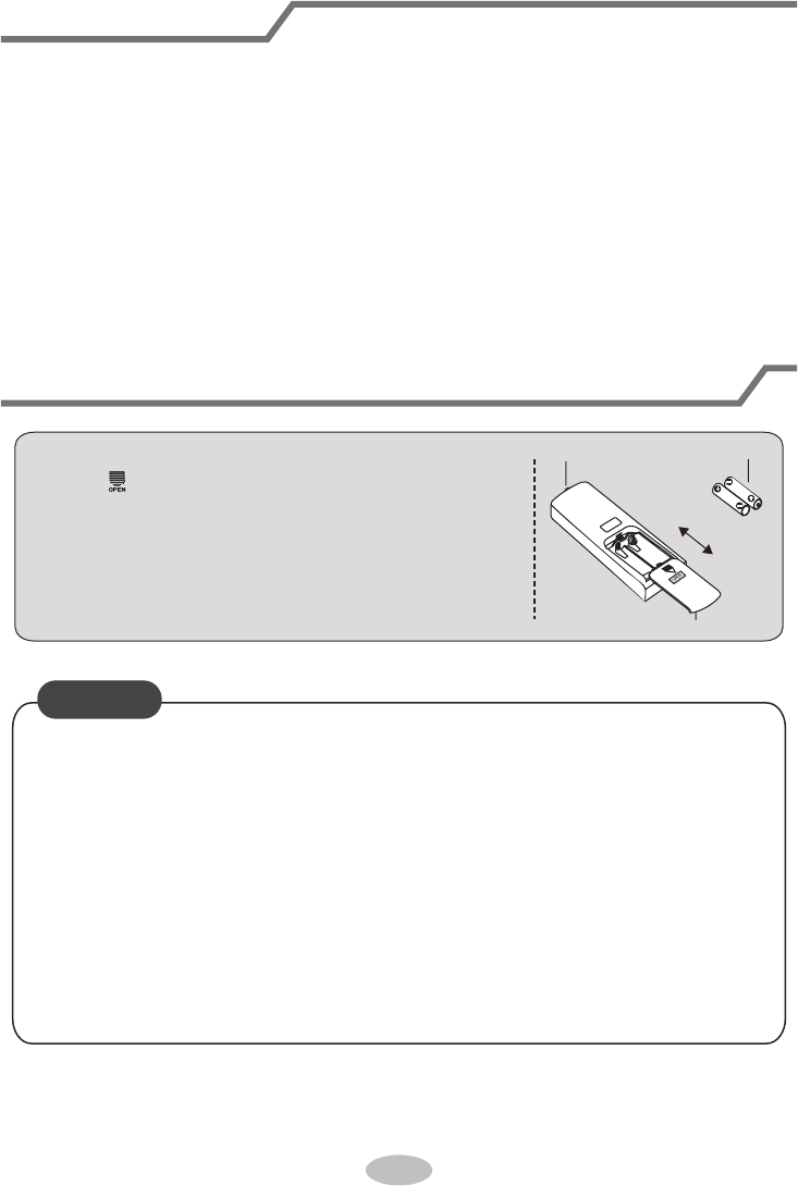
Replacement of batteries in remote controller
1. Press the back side of remote controller marked
with " ", as shown in the fig, and then push out
the cover of battery box along the arrow direction.
2. Replace two 7# (AAA 1.5V) dry batteries, and
make sure the position of "+" polar and "-" polar
are correct.
3. Reinstall the cover of battery box.
signal sender battery
Cover of battery box
remove
reinstall
NOTICE
● During operation, point the remote control signal sender at the receiving
window on indoor unit.
● The distance between signal sender and receiving window should be no
more than 8m, and there should be no obstacles between them.
● Signal may be interfered easily in the room where there is fluorescent lamp
or wireless telephone; remote controller should be close to indoor unit during
operation.
● Replace new batteries of the same model when replacement is required.
● When you don’t use remote controller for a long time, please take out the
batteries.
● If the display on remote controller is fuzzy or there’s no display, please
replace batteries.
19
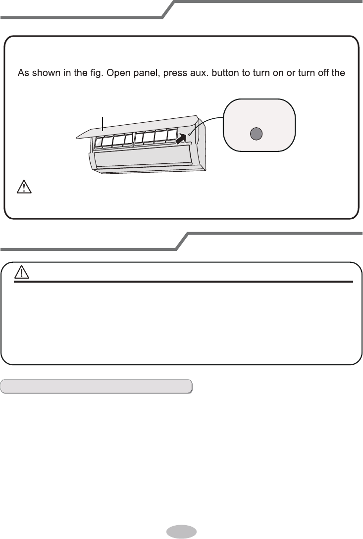
Emergency operation
If remote controller is lost or damaged, please use auxiliary button to turn
on or turn off the air conditioner. The operation in details are as below:
air conditioner. When the air conditioner is turned on, it will operate under
auto mode.
aux. button
panel
Clean and maintenance
■ Turn off the air conditioner and disconnect the power before cleaning the air
conditioner to avoid electric shock.
■ Do not wash the air conditioner with water to avoid electric shock.
■ Do not use volatile liquid to clean the air conditioner.
Clean surface of indoor unit
When the surface of indoor unit is dirty, it is recommended to use a soft dry cloth
or wet cloth to wipe it.
● Do not remove the panel when cleaning it.
WARNING
NOTICE:
WARNING:
Use insulated object to press the auto button
20
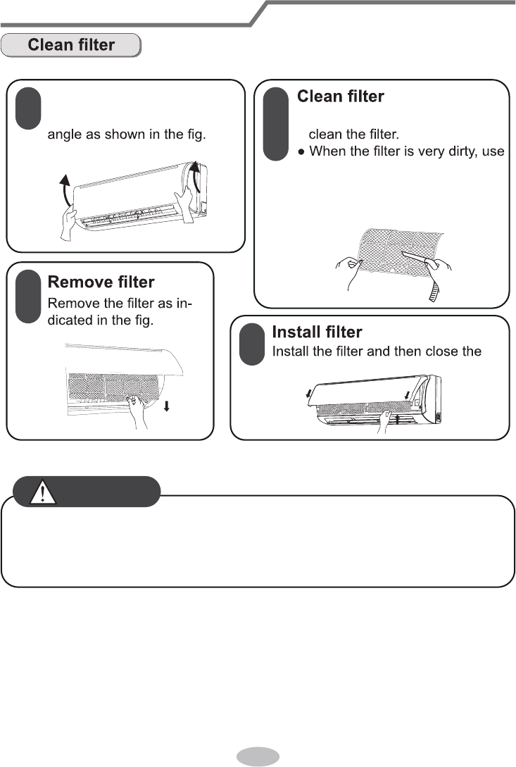
Clean and maintenance
1
2
3
4
Open panel
Pull out the panel to a certain ● Use dust catcher or water to
the water (below 45
℃
(113°F))
to clean it, and then put it in a
shady and cool place to dry.
panel cover tightly.
■ The filter should be cleaned every three months. If there is much dust in the
operation environment, clean frequency can be increased.
■ After removing the filter, do not touch fins to avoid injury.
■ Do not use fire or hair dryer to dry the filter to avoid deformation or fire hazard.
WARNING
21
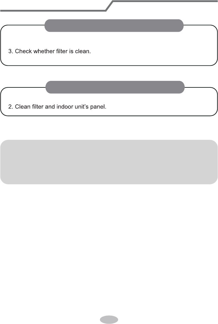
Clean and maintenance
1. Check whether air inlets and air outlets are blocked.
2. Check whether circuit break, plug and socket are in good condition.
4. Check whether drainage pipe is damaged.
1. Disconnect power supply.
Notice for recovery
1. Many packing materials are recyclable materials.
Please dispose them in appropriate recycling unit.
2. If you want to dispose the air conditioner, please contact local dealer or
consultant service center for the correct disposal method.
NOTICE: Checking before use-season
NOTICE: Checking after use-season
22
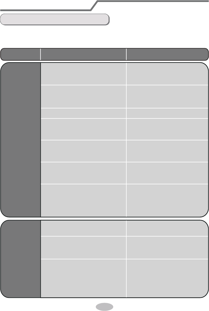
Malfunction analysis
General phenomenon analysis
Please check below items before asking for maintenance. If the malfunction still
can’t be eliminated, please contact local dealer or qualied professionals.
Phenomenon Check items Solution
Indoor unit
can’t receive
remote
controller’s
signal or
remote
controller
has no
action.
● Whether it's interfered severely
(such as static electricity,stable
voltage)?
● Whether remote controller is
within the signal receiving
range?
● Whether there are obstacles?
● Whether remote controller is
pointing at the receiving
window?
● Is sensitivity of remote contro-
ller low; fuzzy display and no
display?
● No display when operating
remote controller?
● Fluorescent lamp in room?
● Pull out the plug. Reinsert
the plug after about 3min, and
then turn on the unit again.
● Signal receiving range is 8m.
● Remove obstacles.
●
Select proper angle and point
the remote controller at the re-
ceiving window on indoor unit.
● Check the batteries. If the
power of batteries is too low,
please replace them.
● Take the remote controller
close to indoor unit.
● Turn off the uoresent lamp
and then try it again.
● Check whether remote cont-
roller appears to be damaged.
If yes, replace it.
No air
emitted
from
indoor
unit
● Air inlet or air outlet of indoor
unit is blocked?
● Eliminate obstacles.
● Under heating mode, indoor
temperature is reached to set
temperature?
● After reaching to set temper-
ature, indoor unit will stop bl-
owing out air.
● Heating mode is turned on just
now?
● In order to prevent blowing
out cold air, indoor unit will be
started after delaying for sev-
eral minutes, which is a nor-
mal phenomenon.
23
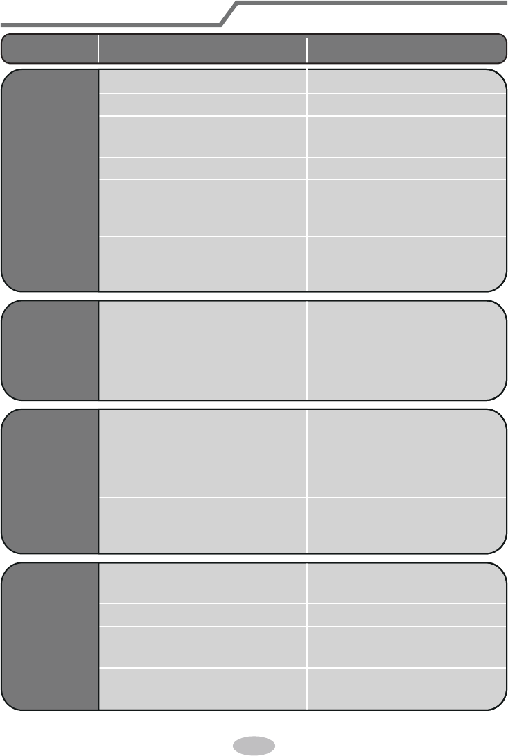
Malfunction analysis
● Power failure?
● Is plug loose?
● Circuit break trips off or
fuse is burnt out?
● Wiring has malfunction?
● Unit has restarted immediately
after stopping operation?
● Whether the function setting
for remote controller is
correct?
● Reset the function.
● Wait for 3min, and then turn
on the unit again.
● Ask professional to replace it.
● Ask professional to replace
circuit break or fuse.
● Reinsert the plug.
● Wait until power recovery.
Air condit-
ioner can’t
operate
Mist is em-
itted from
indoor unit’s
air outlet
● Indoor temperature and hum-
idity is high?
● Because indoor air is cooled
rapidly. After a while, indoor
temperature and humidity will
be decrease and mist will
disappear.
Phenomenon Check items Solution
Set temper-
ature can’t
be adjusted
● Unit is operating under auto
mode?
● Temperature can’t be adju-
sted under auto mode.
Please switch the operation
mode if you need to adjust
temperature.
● Your required temperature
exceeds the set temperature
range?
● Set temperature range:
16
℃
~30
℃
(61~86°F).
Cooling
(heating)
effect is
not good.
● Voltage is too low?
● Wait until the voltage
resumes normal.
● Filter is dirty? ● Clean the filter.
● Set temperature is in proper
range?
● Adjust temperature to proper
range.
● Door and window are open? ● Close door and window.
24
Phenomenon Check items Solution
Odours are
emitted
● Whether there’s odour source,
such as furniture and cigarette,
etc.
● Eliminate the odour source.
● Clean the lter.
Air conditioner
operates nor-
mally suddenly
● Whether there’s interference,
such as thunder, wireless
devices, etc.
● Disconnect power, put back
power, and then turn on the
unit again.
“Wat er
owing”
noise
● Air conditioner is turned on or
turned off just now?
● The noise is the sound of
refrigerant owing inside
the unit, which is a normal
phenomenon.
Cracking
noise
● Air conditioner is turned on or
turned off just now?
● This is the sound of friction
caused by expansion and/or
contraction of panel or other
parts due to the change of
temperature.
Malfunction analysis
25
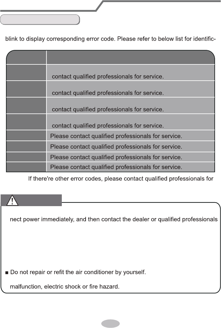
Error Code
● When air conditioner status is abnormal, temperature indictor on indoor unit will
ation of error code.
Error code
E5
E6
E8
H6
C5
F1
F2
Troubleshooting
It can be eliminated after restarting the unit. If not, please
It can be eliminated after restarting the unit. If not, please
It can be eliminated after restarting the unit. If not, please
It can be eliminated after restarting the unit. If not, please
F0
Note:
service.
Malfunction analysis
■ When below phenomenon occurs, please turn off air conditioner and discon-
for service.
● Power cord is overheating or damaged.
● There’s abnormal sound during operation.
● Air switch trips off frequently.
● Air conditioner gives off burning smell.
● Indoor unit is leaking.
■ If the air conditioner operates under abnormal conditions, it may cause
WARNING
26
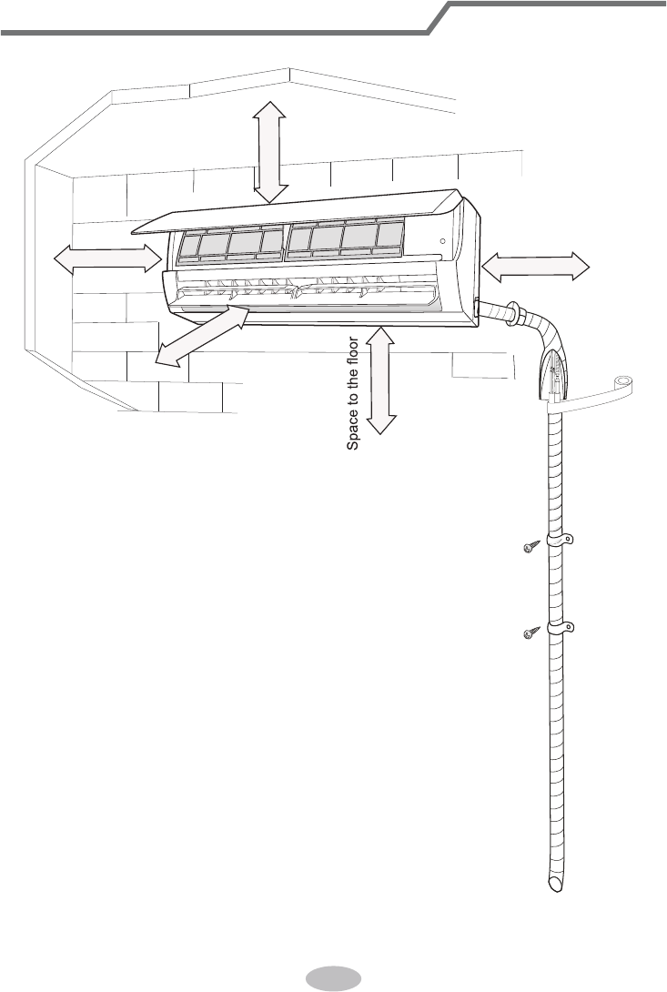
Installation dimension diagram
At least 250cm
At least 15cm
At least 300cm
Space to the ceiling
Space to the obstruction
At least 15cm
Space to the wall
Space to the wall
At least 15cm
27
To ensure safety, please be mindful of the following precautions.
Warning
When installing or relocating the unit, be sure to keep the refrigerant
circuit free from air or substances other than the specified refrigerant.
Any presence of air or other foreign substance in the refrigerant circuit will cause
system pressure rise or compressor rupture, resulting in injury.
When installing or moving this unit, do not charge the refrigerant which
is not comply with that on the nameplate or unqualified refrigerant.
Otherwise, it may cause abnormal operation, wrong action, mechanical
malfunction or even series safety accident.
When refrigerant needs to be recovered during relocating or repairing the
unit, be sure that the unit is running in cooling mode.Then, fully close the
valve at high pressure side (liquid valve).About 30-40 seconds later, fully
close the valve at low pressure side (gas valve), immediately stop the unit
and disconnect power. Please note that the time for refrigerant recovery
should not exceed 1 minute.
If refrigerant recovery takes too much time, air may be sucked in and cause
pressure rise or compressor rupture, resulting in injury.
During refrigerant recovery, make sure that liquid valve and gas valve are
fully closed and power is disconnected before detaching the connection pipe.
If compressor starts running when stop valve is open and connection pipe is not
yet connected, air will be sucked in and cause pressure rise or compressor
rupture, resulting in injury.
When installing the unit, make sure that connection pipe is securely
connected before the compressor starts running.
If compressor starts running when stop valve is open and connection pipe is not
yet connected, air will be sucked in and cause pressure rise or compressor
rupture, resulting in injury.
Prohibit installing the unit at the place where there may be leaked corrosive
gas or flammable gas.
If there leaked gas around the unit, it may cause explosion and other accidents.
Do not use extension cords for electrical connections. If the electric wire
is not long enough, please contact a local service center authorized
and ask for a proper electric wire.
Poor connections may lead to electric shock or fire.
Use the specified types of wires for electrical connections between the
indoor and outdoor units. Firmly clamp the wires so that their terminals
receive no external stresses.
Electric wires with insufficient capacity, wrong wire connections and insecure
wire terminals may cause electric shock or fire.
Safety precautions for installing and relocating the unit
28
1. There should be no obstruction near air inlet and air outlet.
2. Select a location where the condensation water can be dispersed easily and
won't affect other people.
3. Select a location which is convenient to connect the outdoor unit and near the
power socket.
4. Select a location which is out of reach for children.
5. The location should be able to withstand the weight of indoor unit and won't
increase noise and vibration.
6. The appliance must be installed 2.5m above oor.
7. Don't install the indoor unit right above the electric appliance.
8. Please try your best to keep way from uorescent lamp.
Tools for installation
Selection of installation location
1 Level meter 2 Screw driver 3 Impact drill
4 Drill head 5 Pipe expander 6 Torque wrench
7 Open-end wrench 8 Pipe cutter 9 Leakage detector
10 Vacuum pump 11 Pressure meter 12 Universal meter
13 Inner hexagon spanner 14 Measuring tape
Note:
● Please contact the local agent for installation.
● Don't use unqualied power cord.
Basic requirement
Indoor unit
Installing the unit in the following places maycause malfunction. If it is unavoidable,
please consult the local dealer:
1. The place with strong heat sources,
vapors, ammable or explosive gas
, or
volatile objects spread in the air.
2. The place with high-frequency devices (such as welding machine, medical
equipment).
3. The place near coast area.
4.
The place with oil or fumes in the air.
5. The place with sulfureted gas.
6. Other places with special circumstances.
7. Do not use the unit in the immediate surroundings of a laundry a bath a
shower or a swimming pool.
29
Requirements for electric connection
Safety precaution
Grounding requirement
1. Must follow the electric safety regulations when installing the unit.
2. According to the local safety regulations, use qualied power supply circuit and
circuit break.
3. Make sure the power supply matches with the requirement of air conditioner.
Unstable power supply or incorrect wiring or malfunction. Please install proper
power supply cables before using the air conditioner.
4. Properly connect the live wire, neutral wire and grounding wire of power socket.
5. Be sure to cut off the power supply before proceeding any work related to
electricity and safety.
6. Do not put through the power before nishing installation.
7. If the supply cord is damaged, it must be replaced by the manufacturer, its
service agent or similarly qualied persons in order to avoid a hazard.
8. The temperature of refrigerant circuit will be high, please keep the interconnec-
tion cable away from the copper tube.
9. The appliance shall be installed in accordance with national wiring regulations.
10.Installation must be performed in accordance with the requirement of NEC
and CEC by authorized personnel only
1. The air conditioner is the rst class electric appliance. It must be properly
grounding with specialized grounding device by a professional. Please make
sure it is always grounded effectively, otherwise it may cause electric shock.
2. The yellow-green wire in air conditioner is grounding wire, which can't be used
for other purposes.
3. The grounding resistance should comply with national electric safety regulations.
4. The appliance must be positioned so that the plug is accessible.
5. An all-pole disconnection switch having a contact separation of at least 3mm in
all poles should be connected in xed wiring. For models with a power plug,
make sure the plug is within reach after installation.

Left
Wall
Φ70mm
Right
Mark in the middle of it
Level meter
Rear piping hole
Wall
Space
to the
wall
above
150mm
Space
to the
wall
above
150mm
Φ70mm
Rear piping hole
QE:
QD:
Left
Wall
Φ55mm
Right
Mark in the middle of it
Level meter
Rear piping hole
Wall
Space
to the
wall
above
150mm
Space
to the
wall
above
150mm
Φ55mm
Rear piping hole
QC:
Left
Wall
Φ55mm
Right
Mark in the middle of it
Level meter
Rear piping hole
Wall
Space
to the
wall
above
150mm
Space
to the
wall
above
150mm
Φ55mm
Rear piping hole
Left
Wall
Φ55mm
Right
Mark in the middle of it
Level meter
Rear piping hole
Wall
Space
to the
wall
above
150mm
Space
to the
wall
above
150mm
Φ55mm
Rear piping hole
QB:
30
Installation of indoor unit
Step one: choosing installation location
Step two: install wall-mounting frame
rm it with the client.
1. Hang the wall-mounting frame on the wall; adjust it in horizontal position with the
plastic expansion particles in the holes.
3. Fix the wall-mounting frame on the wall with tapping screws (ST4.2X25TA) and
.
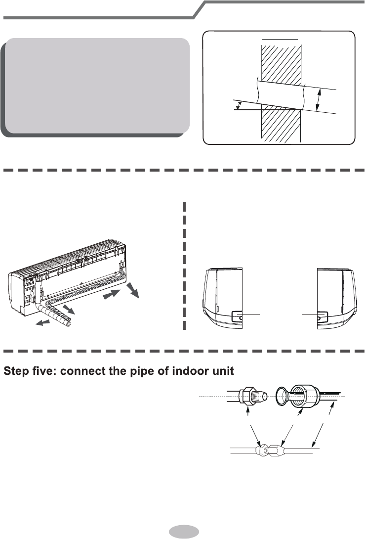
1. Choose the position of piping hole according to the direction of outlet pipe. The
position of piping hole should be a little lower than the wall-mounted frame,
shown as below.
Step three: open piping hole
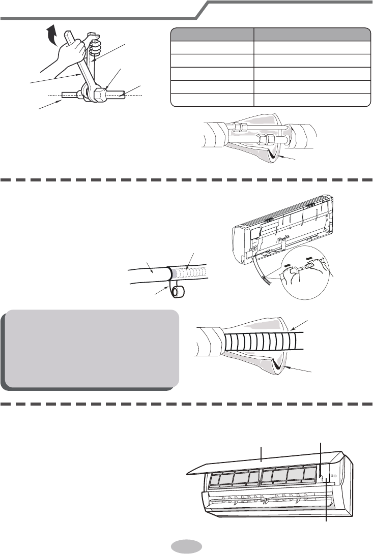
2. Open a piping hole with the diameter of Φ55 or Φ70 on the selected outlet pipe
position.In order to drain smoothly, slant the piping hole on the wall slightly
downward to the outdoor side with the gradient of 5-10°.
31
1. Aim the pipe joint at the corresponding
bellmouth.
2. Pretightening the union nut with hand.
3. Adjust the torque force by referring to the following sheet. Place the open-end
wrench on the pipe joint and place the torque wrench on the union nut. Tighten
the union nut with torque wrench.
2. When select leading out the pipe
from left or right, please cut off the
corresponding hole on the bottom
case.
cut off
the hole
left right
1. The pipe can be led out in the
direction of right, rear right, left or
rear left.
left
rear left
right
rear right
Step four: outlet pipe
Installation of indoor unit
Indoor
5-10°
outdoor
Φ70/Φ55
Note:
● Pay attention to dust prevention and
take relevant safety measures when
opening the hole.
● The plastic expansion particles are
not provided and should be bought
locally.
union nutpipe joint
pipe
32
4. Wrap the indoor pipe and joint of con-
nection pipe with insulating pipe, and
then wrap it with tape.
Step six: install drain hose
Installation of indoor unit
torque wrench
open-end
wrench
indoor pipe
pipe
union nut
Hex nut diameter Tightening torque (N
.
m)
Φ 6
Φ 9.52
Φ 12
Φ 16
Φ 19
30~40
45~55
60~65
70~75
15~20
insulating pipe
1. Connect the drain hose to the outlet pipe of
indoor unit.
2. Bind the joint with tape.
outlet
pipe
drain hose
drain hose
tape
outlet pipe
drain hose
insulating pipe
Note:
● Add insulating pipe in the indoor
drain hose in order to prevent
condensation.
● The plastic expansion particles are
not provided.
1. Open the panel, remove the screw
on the wiring cover and then take
down the cover.
wiring cover
screw
panel
Step seven: connect wire of indoor unit
33
4.Put wiring cover back and then tighten the screw.
5.Close the panel.
Installation of indoor unit
Note:
● All wires of indoor unit and outdoor unit should be connected by a professional.
for a new one. Avoid extending the wire by yourself.
installation.
● For the air conditioner without plug, an circuit break must be installed in the line.
The circuit break should be all-pole parting and the contact parting distance
should be more than 3mm.
3. Remove the wire clip; connect the power connection wire to the wiring terminal
with wire clip.
power connection
wire
cable-cross
hole
2. Make the power connection wire go
through the cable-cross hole at the back
of indoor unit and then pull it out from
the front side.
Outdoor unit connection
green
green)
red
black
(yellow-
(brown)
white
(blue)
2 3N(1)
18K
24K :
09K
12K
34
Installation of indoor unit
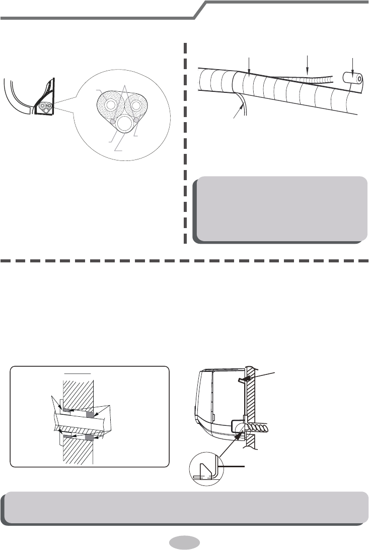
Step eight: bind up pipe
1. Bind up the connection pipe, power
cord and drain hose with the band.
indoor unit
gas
pipe
indoor and
outdoor power cord
liquid pipe
drain hose
band
2. Reserve a certain length of drain
hose and power cord for installation
when binding them. When binding to
a certain degree, separate the indoor
power and then separate the drain
hose.
3. Bind them evenly.
4. The liquid pipe and gas pipe should
be bound separately at the end.
Note:
● The power cord and control wire
can't be crossed or winding.
● The drain hose should be bound
at the bottom.
drain hose
band
connection pipe
indoor power cord
Step nine: hang the indoor unit
1. Put the bound pipes in the wall pipe and then make them pass through the wall
hole.
2. Hang the indoor unit on the wall-mounting frame.
3. Stuff the gap between pipes and wall hole with sealing gum.
4. Fix the wall pipe.
5. Check if the indoor unit is installed rmly and closed to the wall.
Note:
● Do not bend the drain hose too excessively in order to prevent blocking.
indoor
outdoor
wall pipe
sealing gum
upper hook
lower hook of
wall-mounting frame
35
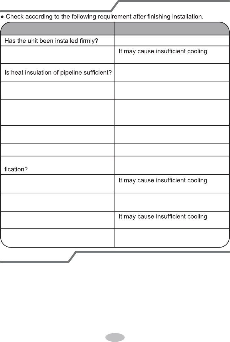
Check after installation
Test operation
Items to be checked Possible malfunction
The unit may drop, shake or emit noise.
Have you done the refrigerant leakage
test?
(heating) capacity.
It may cause condensation and water
dripping.
Is water drained well?
It may cause condensation and water
dripping.
Is the voltage of power supply accord-
ing to the voltage marked on the
nameplate?
It may cause malfunction or damaging
the parts.
Is electric wiring and pipeline installed
correctly?
It may cause malfunction or damaging
the parts.
Is the unit grounded securely? It may cause electric leakage.
Does the power cord follow the speci-
It may cause malfunction or damaging
the parts.
Is there any obstruction in the air inlet
Is the inlet and outlet of piping hole
been covered?
and outlet?
(heating) capacity.
The dust and sundries caused during
installation are removed?
It may cause malfunction or damaging
the parts.
The gas valve and liquid valve of
connection pipe are open completely?
(heating) capacit
It may cause insufficient cooling
(heating) capacity or waster eletricity.
y.
1. Preparation of test operation
● The client approves the air conditioner.
● Specify the important notes for air conditioner to the client.
2. Method of test operation
● Put through the power, press ON/OFF button on the remote controller to start
operation.
● Press MODE button to select AUTO, COOL, DRY, FAN and HEAT to check
whether the operation is normal or not.
● If the ambient temperature is lower than 16
℃(61°F)
, the air conditioner can’t
start cooling.
36
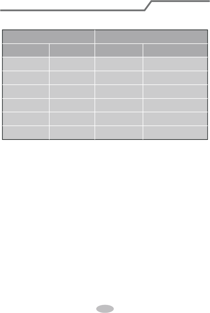
1. Standard length of connection pipe
● 5m, 7.5m, 8m.
4. The additional refrigerant oil and refrigerant charging required after prolonging
connection pipe
● After the length of connection pipe is prolonged for 10m at the basis of
standard length, you should add 5ml of refrigerant oil for each additional 5m
of connection pipe.
● The calculation method of additional refrigerant charging amount (on the basis
of liquid pipe):
● Basing on the length of standard pipe, add refrigerant according to the
requirement as shown in the table. The additional refrigerant charging amount
per meter is different according to the diameter of liquid pipe. See the
following sheet.
Additional refrigerant charging amount = prolonged length of liquid pipe ×
additional refrigerant charging amount per meter
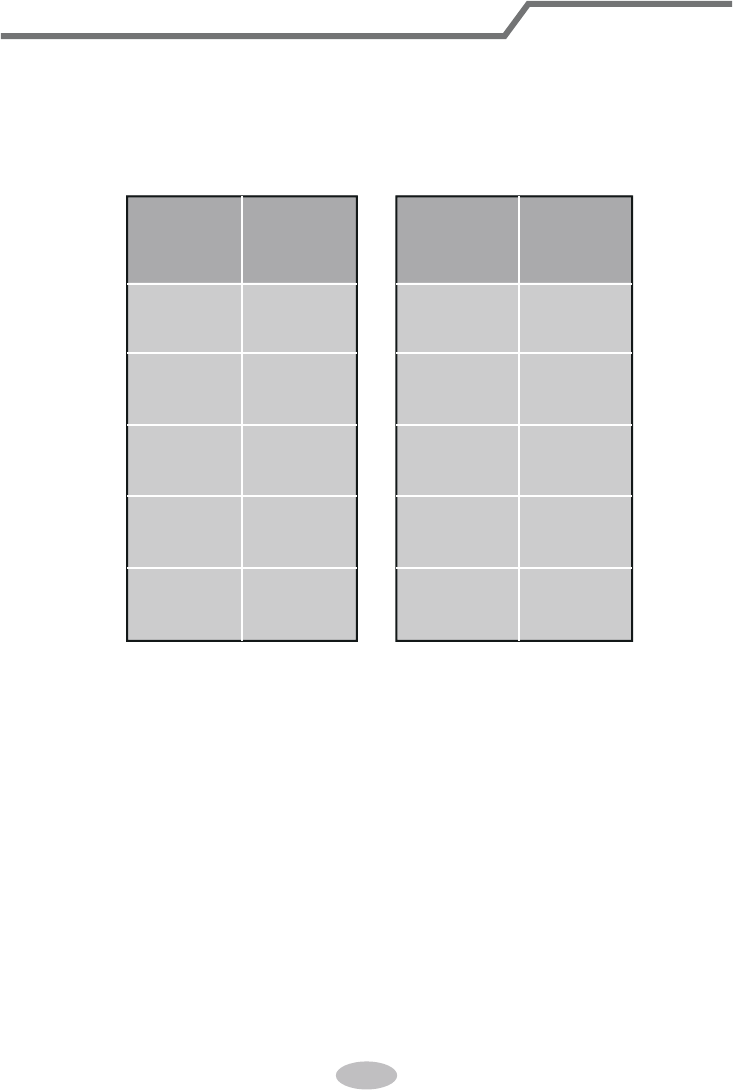
2.Min. length of connection pipe is 3m.
3.
Max. length of connection pipe.
Configuration of connection pipe
15 25
15 30
15 30
20 30
25 30
Cooling
capacity
Max length
of connec-
tion pipe
Cooling
capacity
Max length
of connec-
tion pipe
5000Btu/h
(1465W)
7000Btu/h
(2051W)
9000Btu/h
(2637W)
12000Btu/h
(3516W)
18000Btu/h
(5274W)
24000Btu/h
(7032W)
28000Btu/h
(8204W)
36000Btu/h
(10548W)
42000Btu/h
(12306W)
48000Btu/h
(14064W)
37
Additional refrigerant charging amount for R22, R407C, R410A and R134a
Diameter of connection pipe
Liquid pipe(mm) Gas pipe(mm)
Φ6
Φ6 or Φ9.52
Φ12
Φ16
Φ19
Φ22.2
Φ9.52 or Φ12
Φ16 or Φ19
Φ19 or Φ22.2
Φ25.4 or Φ31.8
_
_
Cooling only(g/m) Cooling and heating(g/m)
15
15
30
60
250 250
350350
120
120
50
20
Outdoor unit throttle
Conguration of connection pipe
38
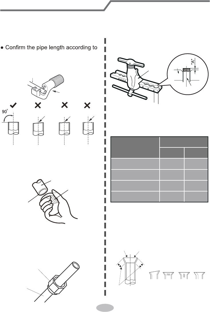
Pipe expanding method
Note:
Improper pipe expanding is the main cause of refrigerant leakage. Please expand
the pipe according to the following steps:
A: Cut the pipe
the distance of indoor unit and
outdoor unit.
● Cut the required pipe with pipe cutter.
pipe
pipe cutter
leaning uneven burr
B: Remove the burrs
● Remove the burrs with shaper and
prevent the burrs from getting into
the pipe.
downwards
pipe
shaper
C: Put on suitable insulating pipe
D: Put on the union nut
● Remove the union nut on the indoor
connection pipe and outdoor valve;
install the union nut on the pipe.
union pipe
pipe
E: Expand the port
● Expand the port with expander.
Note:
● "A" is different according to the
diameter, please refer to the sheet
below:
expander
hard
mold
pipe
F: Inspection
● Check the quality of expanding port.
If there is any blemish, expand the
port again according to the steps
above.
the length is equal
improper expanding
leaning
damaged
surface
crack uneven
thickness
smooth surface
Outer diameter
(mm)
A(mm)
Max Min
Φ6 - 6.35(1/4")
Φ9.52(3/8")
Φ12-12.7(1/2")
Φ15.8-16(5/8")
1.3 0.7
1.6 1.0
1.8 1.0
2.4 2.2
600005060117
